US8854798B1 - Transmitter holder apparatus and method - Google Patents
Transmitter holder apparatus and methodDownload PDFInfo
- Publication number
- US8854798B1 US8854798B1US12/587,140US58714009AUS8854798B1US 8854798 B1US8854798 B1US 8854798B1US 58714009 AUS58714009 AUS 58714009AUS 8854798 B1US8854798 B1US 8854798B1
- Authority
- US
- United States
- Prior art keywords
- bezel
- assembly
- transmitter assembly
- transmitter
- recess
- Prior art date
- Legal status (The legal status is an assumption and is not a legal conclusion. Google has not performed a legal analysis and makes no representation as to the accuracy of the status listed.)
- Expired - Fee Related, expires
Links
Images


Classifications
- H—ELECTRICITY
- H02—GENERATION; CONVERSION OR DISTRIBUTION OF ELECTRIC POWER
- H02G—INSTALLATION OF ELECTRIC CABLES OR LINES, OR OF COMBINED OPTICAL AND ELECTRIC CABLES OR LINES
- H02G3/00—Installations of electric cables or lines or protective tubing therefor in or on buildings, equivalent structures or vehicles
- H02G3/02—Details
- H02G3/08—Distribution boxes; Connection or junction boxes
- H02G3/14—Fastening of cover or lid to box
Definitions
- the inventionrelates to a transmitter holder apparatus and method.
- the inventionrelates to a bezel with a front surface, sides and a flat back where the front surface includes a recess.
- a transmitter assemblyis provided where the transmitter assembly is configured to fit within the recess in the front surface of the bezel.
- a connector deviceis provided for removably connecting the transmitter assembly with the bezel.
- controls for televisions, music systems, ceiling fans, lighting systems, window shades, door coverings and curtainsare all known to include control devices for remote control and operation. Where any one of the controls are to be found at any one time is typically anyone's guess, however.
- a series of inventionshave addressed the problem of locating the remote controls including audio and visual displays. These “solutions”, however, create additional problems of how to locate the locator.
- a wireless wall mountis connected on top of an existing wall switch to receive and support a wireless remote control.
- the mounting structurecompletely covers the existing switch and thus requires a recess to receive the existing switch used for turning the switch on and off. Further, the wireless remote extends from the mounting structure so that the user may grasp the sides to pull it from, and replace it with, the mount.
- the mounting structure and remotethus extend significantly away from the existing wall switch in an intrusive, invasive, manner and generally add a cluttered appearance to the wall switch.
- the transmitter holder apparatus of the present inventionincludes a bezel with a front surface, sides and a flat back where the front surface includes a recess.
- a transmitter assemblyis provided where the transmitter assembly is configured to fit within the recess in the front surface of the bezel.
- a connector deviceis provided for removably connecting the transmitter assembly with the bezel.
- the connector deviceincludes a metal plate and a magnet in cooperative relationship such that the magnet removably connects with the metal plate.
- the metal plateis connected with the bezel in the recess and the recess includes a base and the metal plate extends out from the recess base.
- the magnetis connected with the transmitter assembly and the transmitter assembly includes a chamber such that the metal plate fits within the chamber in the transmitter assembly.
- the transmitter assemblyincludes an operating surface and the operating surface of the transmitter assembly extends above the front surface of the bezel when the transmitter assembly is connected with the bezel.
- the transmitter assemblyincludes controls for operation of a device in an operating surface of the transmitter assembly.
- the deviceis a curtain assembly.
- the controlscontrol movement of a curtain assembly such that a shade moves up and down.
- the controlscontrol movement of a curtain assembly such that a shade moves up and down a percentage of a total distance.
- the connector deviceis asymmetrical such that the transmitter assembly is always connected with the bezel in only one particular orientation.
- the term “asymmetrical”is given its common meaning such that it is clear that what is meant is that, according to one embodiment, the connector device has a particular location within the recess of the bezel and on the transmitter assembly that prevents the transmitter assembly from being connected with the bezel upside down, for example only.
- a transmitter holder apparatusincludes a bezel with a front surface, sides and a back where the front surface includes a recess.
- a transmitter assembly for operation of an applianceis provided where the transmitter assembly includes controls for operation of the appliance and where the transmitter assembly includes a power source and where the transmitter assembly is configured to fit within the recess in the front surface of the bezel.
- a connector device for removably connecting the transmitter assembly with the bezelis provided where the connector device includes a metal plate and a magnet in cooperative relationship such that the magnet removably connects with the metal plate.
- the recess in the front surface of the bezelextends beyond the back of the bezel. In a further aspect, the recess in the bezel is conformed to fit within an electrical switch box.
- switch boxis used with its common meaning as understood by those of ordinary skill in the art. That is, it is used to denote a common switch box which is built to contain the elements of an electrical switch used to turn an appliance on or off.
- Common electrical switchesinclude a toggle switch, for example only and not by way of limitation, movable up and down. Such electrical switches are hardwired to the appliance or an electrical outlet to which an appliance is connected.
- the switch boxthus, is the box within which the electrical power connections and electrical switch components are located.
- the switch boxis typically attached to a supporting stud or beam behind a wall with an open part of the switch box facing toward an access opening in the wall.
- the finished electrical switch box and switchincludes a cover plate that lays flats against the wall surface and covers the switch box opening and components within the switch box from view.
- the transmitter assemblyincludes a removal assist device.
- the removal assist deviceincludes a cut out in the transmitter assembly.
- the applianceis a curtain assembly and the curtain assembly includes a shade for covering an opening and the controls control operation of the curtain assembly such that the shade moves up to an upper limit and down to a lower limit.
- the applianceis a curtain assembly and the curtain assembly includes a shade for covering an opening and the controls include a first control, a second control and a third control and the first control controls movement of the curtain assembly such that approximately twenty-five per-cent of an opening is covered by the shade, the second control controls movement of the curtain assembly such that approximately fifty per-cent of an opening is covered by the shade and the third control controls movement of the curtain assembly such that approximately seventy-five per-cent of an opening is covered by the shade.
- the connector deviceis asymmetrical such that the transmitter assembly can only be connected with the bezel in one particular orientation.
- a transmitter holder method for utilizing a transmitterincludes the steps of: providing a bezel with a front surface, sides and a flat back where the front surface includes a recess; providing a transmitter assembly for operation of an appliance where the transmitter assembly includes controls for operation of the appliance and where the transmitter assembly includes a power source and where the transmitter assembly is configured to fit within the recess in the front surface of the bezel; providing a connector device for removably connecting the transmitter assembly with the bezel where the connector device includes a metal plate and a magnet in cooperative relationship such that the magnet removably connects with the metal plate; and placing the transmitter assembly with the bezel such that the metal plate and the magnet hold the transmitter assembly in connection with the bezel.
- the metal plateis connected with the bezel and the magnet is connected with the transmitter assembly.
- the applianceis a curtain assembly and the curtain assembly includes a shade for covering an opening and the controls control operation of the curtain assembly such that the shade moves up to an upper limit and down to a lower limit.
- the applianceis a curtain assembly and the curtain assembly includes a shade for covering an opening and the controls include a first control, a second control and a third control and the first control controls movement of the curtain assembly such that approximately twenty-five per-cent of an opening is covered by the shade, the second control controls movement of the curtain assembly such that approximately fifty per-cent of an opening is covered by the shade and the third control controls movement of the curtain assembly such that approximately seventy-five per-cent of an opening is covered by the shade.
- FIG. 1is an exploded view of the transmitter holder apparatus according to one embodiment
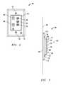
- FIG. 2is a front view of the invention of FIG. 1 with a transmitter connected with the bezel;
- FIG. 3is a side view of the invention of FIG. 1 with a transmitter connected with the bezel;
- FIG. 4is a front view of an opening with a curtain assembly with a shade lowered for twenty-five per-cent coverage of the opening, and using dotted lines to indicate fifty per-cent coverage and seventy-five per-cent coverage of the opening;
- FIG. 5is an exploded view of another embodiment of the transmitter holder apparatus connected with an electrical switch box and including a remove assist device;
- FIG. 6is a perspective view of the invention of FIG. 5 with the transmitter connected with the bezel and flush with the surface of the bezel.
- the transmitter holder apparatus 10includes a bezel 12 and a transmitter assembly 14 .
- Bezel 12includes openings 16 .
- Screws 18pass through openings 16 and connect bezel 12 with wall inserts 20 .
- Wall inserts 20are screwed or hammered into a wall (not shown) and provide a gripping material into which screws 18 are driven, as is known in the art.
- Wall inserts 20may be placed at any location on a surface and, therefore, bezel 12 may be located as and where needed or most convenient to the user.
- bezel 12includes a front surface 22 , sides 24 and back 26 .
- the sides 24are raised sides as shown in the manner of typical wall switch cover plates known in the art.
- the back 26 in this embodimentis flat.
- bezel 12lays flat against the surface of the wall and the front surface 22 extends outwardly from the wall the width of sides 24 .
- Recess 28 in the front surface 22 of bezel 12is provided.
- Recess 28includes sides 30 that extend below or into front surface 22 .
- a base 32 connected with sides 30 and base 32is a flat surface parallel to the front surface 22 . This feature results in the creation of a uniform and unobtrusive appearance when transmitter assembly 14 is removed.
- base 32includes metal plate 34 .
- Metal plate 34can be any ferrous metal such as steel, for example only, or material to which magnets are attracted.
- Transmitter assembly 14includes a back case 36 , a printed circuit board 38 , battery 40 and controls 42 .
- Controls 42include buttons 44 , 46 , 48 , 50 , and 52 , as will be discussed more fully hereafter with regard to FIG. 4 , for controlling a device or appliance 54 (shown in FIG. 4 ).
- transmitter assembly 14includes a magnet 56 connected to back case 36 .
- back case 36includes a chamber 58 .
- Chamber 58is conformed to receive metal plate 34 . That is, metal plate 34 forms a “male” member protruding from the base 32 of recess 28 as shown. Chamber 58 then forms a “female” receiver for metal plate 34 .
- transmitter assembly 14is connected with bezel 12 .
- magnet 56cooperates with metal plate 34 to removably hold transmitter assembly 14 in place in the recess 28 of bezel 12 .
- Transmitter assembly 14further includes a front cover 60 .
- Front cover 60connects with back case 36 enclosing printed circuit board 38 , battery 40 , and controls 42 between them.
- Front cover 60includes holes 62 through which buttons 44 , 46 , 48 , 50 and 52 protrude as shown in FIGS. 2 , 3 , and 6 .
- FIG. 1also illustrates another aspect of the invention in which the connector device is asymmetrical. That is, according to this aspect, the metal plate 34 , for example only, is located off center with regard to the area defined by recess 28 . As shown, for example only, FIG. 1 illustrates the metal plate 34 located above the mid point of recess 28 .
- transmitter assembly 14can be connected with bezel 12 within recess 28 in only one orientation. This solves a common problem of attaching the transmitter assembly upside down inadvertently.
- transmitter assembly 14is shown connected with bezel 12 . It is illustrated that, preferably, recess 28 (not shown) is formed to fit transmitter assembly 14 in length and width and to receive some part of the depth of transmitter assembly 14 , some of the back case 36 , within recess 28 .
- the back of back case 36(not shown) is flat as well and meets up with and matches the base 32 of recess 28 .
- the recess 28is filled by the transmitter assembly 14 or part thereof.
- the surface 64 of front cover 60is flush with the front surface 22 of bezel 12 as will be discussed more fully hereafter with regard to FIG. 6 .
- back 26 of bezel 12is flat and thus conforms to the flat surface of wall 66 as shown.
- recess 28 in bezel 12is only as deep, therefor, as the width of sides 24 . Nonetheless, this allows bezel 12 to be placed anywhere on any wall 66 the user finds useful and convenient and whether or not an electrical switch box is present.
- transmitter assembly 14does not extend excessively into the surrounding space as some portion of the transmitter assembly 14 is within recess 28 as the surface 64 of front cover 60 of transmitter assembly 14 is flat and rests in parallel relation with the front surface 22 of bezel 12 .
- the sides 68 of transmitter assembly 14protrude just enough however to enable a user to grasp transmitter assembly 14 and pull it from its connection with bezel 12 . The user is then free to take the transmitter assembly 14 wherever needed and then, by placing the transmitter assembly 14 near bezel 12 and recess 28 enable the magnet 56 metal plate 34 combination to secure it in place.
- an appliance 54such as a curtain assembly with a shade 70 , is shown located in a window opening 72 .
- transmitter assembly 14is manipulated by pressing button 44 and causing shade 70 to move to the fully retracted or up position at the top 74 of window opening 72 .
- pressing button 46causes appliance 54 to lower shade 70 to the fully extended or down position at the bottom 76 of window opening 72 .
- button 48lowers the shade 70 twenty-five per-cent as shown in FIG. 4 .
- Button 50lowers shade 70 to the fifty per-cent location 78 and button 52 lowers the shade to the seventy-five per-cent position 80 .
- the controls 42may also be programmed to provide different functions to single appliances or groups of appliances by means of differing number of button presses, by different length of button presses and different sequences of button presses.
- Switch box 82is empty of electrical components normally found therein and contains and opening 84 .
- the opening 84 of switch box 82is located behind wall 66 (not shown).
- An openingis cut in wall 66 such that access to switch box 82 through opening 84 is provided.
- Nails 86are used to connect switch box 82 to wall studs 88 (as shown in FIG. 6 ).
- the opening 84 of switch box 82is facing the back of wall surface 66 .
- Bezel 12is connected directly with switch box 82 by means of screws 18 screwed into attachment points 90 in switch box 82 such that the front surface 22 of bezel 12 lays flat against wall surface 66 as illustrated in FIG. 6 .
- recess 38extends beyond the back 26 of bezel 12 .
- the recessis deeper and, in fact, the recess 38 extends into and is received by the opening 84 in switch box 82 .
- this embodimentenables the transmitter assembly to lay in the same plain as the front surface 22 of bezel 12 as more clearly shown in FIG. 6 .
- an unobtrusive control panel 42fits flush with the bezel 12 just as if an expensive hard wired system had been installed.
- FIG. 5also illustrates an important element of this embodiment of the invention directed to a remove assist device in the form of cut out 92 .
- Cut out 92is created by a mismatch of the form of transmitter assembly 14 and bezel 12 . As shown here and in FIG. 6 , this mismatch is created by eliminating a corner of transmitter assembly 14 .
- a personsimply inserts a finger into the cut out 92 , grasps the transmitter assembly 14 between thumb and finger and removes it.
- remove assist devicesare available such as a ledge, not shown, in recess 28 against which transmitter assembly 14 tilts such that a user can grasp the transmitter assembly 14 and remove it.
- the required element of the instant remove assist deviceis that it maintain transmitter assembly 14 and front cover 60 in essentially parallel alignment on the same plane with the front surface 22 of bezel 12 .
- transmitter assembly 14when transmitter assembly 14 is removed from recess 28 re-securing transmitter assembly 14 in place within recess 28 simply requires the user to move the transmitter assembly 14 close enough to recess 28 that the magnetic attraction between metal plate 34 and magnet 56 is great enough to removably attach the them together.
- an advantage of the present inventionis that with the transmitter assembly 14 removed from bezel 12 , a non obtrusive, flat surface is presented. Further, the fact that the transmitter 14 has been removed is easily determined. Still further, the removably attachable feature of the transmitter assembly 14 allows the user to access it for servicing or remote use easily and inexpensively.
- FIG. 6Another advantage of the present invention is illustrated in the situation in which the transmitter assembly 14 is connected by the connector device, metal plate 34 and magnet 56 for example only, with the bezel 12 .
- a connector devicecould be formed by a combination of hook and loop material or any means now known or hereafter developed in place of the magnet and metal combination described herein.
- recess 28 in bezel 12 in this embodimentis such that when the transmitter assembly 14 is located within the recess 28 , the surface 64 of front cover 60 is level with the front surface 22 of bezel 12 which is essentially level with wall surface 66 .
- an in place device controlis provided that is unobtrusive and that presents an essentially flat control panel for operation of desired devices.
- a further advantage of the present inventionis that it makes use of electrical switch boxes and the familiarity of their location in a structure without requiring any power to be run to the switch box and without requiring a typical switch to be installed. As a result, a user is presented with a fully functional switch at an expected location without the expense of a normal switch.
- the switch boxmay include power connections that are not used by the present invention but which may be accessed when the owner deems it necessary.
Landscapes
- Engineering & Computer Science (AREA)
- Architecture (AREA)
- Civil Engineering (AREA)
- Structural Engineering (AREA)
- Selective Calling Equipment (AREA)
Abstract
Description
Claims (18)
Priority Applications (1)
| Application Number | Priority Date | Filing Date | Title |
|---|---|---|---|
| US12/587,140US8854798B1 (en) | 2009-10-02 | 2009-10-02 | Transmitter holder apparatus and method |
Applications Claiming Priority (1)
| Application Number | Priority Date | Filing Date | Title |
|---|---|---|---|
| US12/587,140US8854798B1 (en) | 2009-10-02 | 2009-10-02 | Transmitter holder apparatus and method |
Publications (1)
| Publication Number | Publication Date |
|---|---|
| US8854798B1true US8854798B1 (en) | 2014-10-07 |
Family
ID=51626986
Family Applications (1)
| Application Number | Title | Priority Date | Filing Date |
|---|---|---|---|
| US12/587,140Expired - Fee RelatedUS8854798B1 (en) | 2009-10-02 | 2009-10-02 | Transmitter holder apparatus and method |
Country Status (1)
| Country | Link |
|---|---|
| US (1) | US8854798B1 (en) |
Cited By (9)
| Publication number | Priority date | Publication date | Assignee | Title |
|---|---|---|---|---|
| WO2017196837A1 (en)* | 2016-05-10 | 2017-11-16 | David Hall | Home automation hybrid universal switch and remote |
| CN107396581A (en)* | 2017-09-22 | 2017-11-24 | 武汉亿维登科技发展有限公司 | A kind of ventilated type outdoor power cabinet system |
| US20180017242A1 (en)* | 2016-07-12 | 2018-01-18 | Abl Ip Holding Llc | Wall mounted battery-powered wireless device |
| US10261162B2 (en)* | 2016-04-26 | 2019-04-16 | Magic Leap, Inc. | Electromagnetic tracking with augmented reality systems |
| US10658131B2 (en)* | 2015-03-20 | 2020-05-19 | Somfy Activites Sa | Remote-control device comprising a portable remote control and a wall mounting |
| US11234549B2 (en) | 2018-01-26 | 2022-02-01 | Current Products Corp. | Grommet drapery system |
| US11244485B2 (en) | 2016-01-19 | 2022-02-08 | Magic Leap, Inc. | Augmented reality systems and methods utilizing reflections |
| US11744393B2 (en) | 2018-01-26 | 2023-09-05 | Current Products Corp. | Tabbed drapery system |
| US12442832B2 (en) | 2022-12-21 | 2025-10-14 | Abl Ip Holding Llc | Wall-mounted controller with anti-tamper feature |
Citations (42)
| Publication number | Priority date | Publication date | Assignee | Title |
|---|---|---|---|---|
| US4815683A (en)* | 1987-10-19 | 1989-03-28 | Laureen Ferrante | Holder for remote control units for TV,VCR and the like |
| USD322244S (en)* | 1989-11-20 | 1991-12-10 | Bishai Mark R | Remote control housing for a curtain positioner |
| US5082229A (en)* | 1990-07-02 | 1992-01-21 | Dahl Robert M | Holder for RCs, schedule guide, and magazine employs transparent rigid sheets and temporary fasteners |
| EP0482252A1 (en)* | 1990-10-23 | 1992-04-29 | Ming Nien | Control device for venetian blinds and curtains |
| US5244173A (en)* | 1991-10-11 | 1993-09-14 | Barry Kulyk | Holder for remote control units |
| US5264761A (en) | 1991-09-12 | 1993-11-23 | Beacon Light Products, Inc. | Programmed control module for inductive coupling to a wall switch |
| US5316249A (en)* | 1992-08-25 | 1994-05-31 | Alfred Anderson | Stand with tether for electronic remote control units |
| US5341941A (en)* | 1993-06-28 | 1994-08-30 | Marlor Thomas W | Combined storage and exercise-therapy apparatus |
| US5458311A (en) | 1994-02-25 | 1995-10-17 | Casablanca Fan Company | Wall mount for a wireless remote control |
| US5603451A (en)* | 1995-03-31 | 1997-02-18 | John W. Helander | Aesthetic thermostat |
| US5648757A (en)* | 1994-10-24 | 1997-07-15 | Vernace; Salvatore J. | Remote control protective holder and detection device |
| US5790021A (en)* | 1996-11-27 | 1998-08-04 | Mickel; Ivor | Remote control finder |
| US6085826A (en)* | 1998-01-27 | 2000-07-11 | Navio, Inc. | Runner with line tensioning capabilities, guide rails for electrically-opened and closed curtains, and guide rails for manually-opened and closed curtains |
| US6305656B1 (en)* | 1999-02-26 | 2001-10-23 | Dash-It Usa Inc. | Magnetic coupler and various embodiments thereof |
| US6320503B1 (en)* | 2000-09-21 | 2001-11-20 | Vanessa Dunn | Remote control paging and organizing assembly |
| US6355885B1 (en) | 1996-05-02 | 2002-03-12 | William J. Rintz | Sub frame assembly for light switch assembly |
| US20020105763A1 (en)* | 2001-02-06 | 2002-08-08 | Wei-Cheng Yeh | Motor-driven curtain assembly and motor control device therefor |
| US6522078B1 (en) | 1999-08-27 | 2003-02-18 | Horiba, Ltd. | Remotely controlled power supply switching system |
| US6598652B1 (en)* | 1998-06-17 | 2003-07-29 | C.A.S. Locks S.L. | Distance-controlled electrically powered unit for actuating rail-mounted curtains |
| US20040070516A1 (en)* | 2000-12-10 | 2004-04-15 | Nielsen Martin S. | Remote control device and method of configuration of such a remote control device |
| US6751486B1 (en)* | 1999-10-06 | 2004-06-15 | Alcatel | Hands free charger for a handset and handset |
| US6769658B2 (en)* | 2002-12-19 | 2004-08-03 | James R. Stokes | Remote control holder device |
| US6816713B2 (en)* | 2001-04-04 | 2004-11-09 | E-Lead Electronic Co., Ltd. | Switching and retaining device for use in cellular phones and peripheral communication equipment thereof |
| US20050034374A1 (en)* | 2001-11-14 | 2005-02-17 | Ebbe Ulrik Vagn | Operator system and an aperture member comprising such a system |
| US6922333B2 (en)* | 2003-03-26 | 2005-07-26 | Benq Corporation | Detachable keyboard structure |
| US20050168338A1 (en)* | 2003-12-22 | 2005-08-04 | Sharper Image Corporation | Article locator apparatus with remote tokens |
| US6967565B2 (en) | 2003-06-27 | 2005-11-22 | Hx Lifespace, Inc. | Building automation system |
| US6983126B1 (en)* | 2001-10-15 | 2006-01-03 | Steve Saalman | Audio transmitter and remote control receiver and storage apparatus |
| USD522999S1 (en)* | 2004-10-29 | 2006-06-13 | Victoria Smith-Adams | Universal remote pager |
| US7071836B2 (en)* | 2001-08-06 | 2006-07-04 | Somfy Sas | Remote control that can switch between operating modes |
| US7079045B2 (en)* | 2001-08-06 | 2006-07-18 | Somfy Sas | Remote control with change of operating mode |
| US20060250764A1 (en)* | 2005-05-09 | 2006-11-09 | Apple Computer, Inc. | Universal docking station for hand held electronic devices |
| US20070035917A1 (en)* | 2005-08-09 | 2007-02-15 | Apple Computer, Inc. | Methods and apparatuses for docking a portable electronic device that has a planar like configuration and that operates in multiple orientations |
| US7187283B2 (en)* | 2004-03-18 | 2007-03-06 | Se-Kure Controls, Inc. | Security system for a portable article |
| US7284791B1 (en)* | 2003-12-09 | 2007-10-23 | Tommy Dale Wright | Remote control innovator |
| US20070279245A1 (en)* | 2006-05-22 | 2007-12-06 | Steven Sholem | Remote control holder |
| US7372355B2 (en) | 2004-01-27 | 2008-05-13 | Black & Decker Inc. | Remote controlled wall switch actuator |
| US20080232061A1 (en)* | 2007-03-21 | 2008-09-25 | Asustek Computer Inc. | Portable Electronic System |
| US7499261B2 (en)* | 2006-07-07 | 2009-03-03 | Lutron Electronics Co., Inc. | Load control device having a split enclosure |
| US20090103228A1 (en)* | 2007-10-18 | 2009-04-23 | Elbex Video Ltd. | Method and Apparatus for Remotely Operating AC Powered Appliances from Video Interphones or Shopping Terminals |
| US20090121842A1 (en)* | 2007-11-14 | 2009-05-14 | Elbex Video Ltd. | Method and Apparatus for Operating AC Powered Appliances Via Video Interphones, Two Way IR Drivers and Remote Control Devices |
| US7723939B2 (en)* | 2006-05-23 | 2010-05-25 | Lutron Electronics Co., Inc. | Radio-frequency controlled motorized roller shade |
- 2009
- 2009-10-02USUS12/587,140patent/US8854798B1/ennot_activeExpired - Fee Related
Patent Citations (47)
| Publication number | Priority date | Publication date | Assignee | Title |
|---|---|---|---|---|
| US4815683A (en)* | 1987-10-19 | 1989-03-28 | Laureen Ferrante | Holder for remote control units for TV,VCR and the like |
| USD322244S (en)* | 1989-11-20 | 1991-12-10 | Bishai Mark R | Remote control housing for a curtain positioner |
| US5082229A (en)* | 1990-07-02 | 1992-01-21 | Dahl Robert M | Holder for RCs, schedule guide, and magazine employs transparent rigid sheets and temporary fasteners |
| EP0482252A1 (en)* | 1990-10-23 | 1992-04-29 | Ming Nien | Control device for venetian blinds and curtains |
| US5264761A (en) | 1991-09-12 | 1993-11-23 | Beacon Light Products, Inc. | Programmed control module for inductive coupling to a wall switch |
| US5244173A (en)* | 1991-10-11 | 1993-09-14 | Barry Kulyk | Holder for remote control units |
| US5316249A (en)* | 1992-08-25 | 1994-05-31 | Alfred Anderson | Stand with tether for electronic remote control units |
| US5341941A (en)* | 1993-06-28 | 1994-08-30 | Marlor Thomas W | Combined storage and exercise-therapy apparatus |
| US5458311A (en) | 1994-02-25 | 1995-10-17 | Casablanca Fan Company | Wall mount for a wireless remote control |
| US5648757A (en)* | 1994-10-24 | 1997-07-15 | Vernace; Salvatore J. | Remote control protective holder and detection device |
| US5603451A (en)* | 1995-03-31 | 1997-02-18 | John W. Helander | Aesthetic thermostat |
| US6355885B1 (en) | 1996-05-02 | 2002-03-12 | William J. Rintz | Sub frame assembly for light switch assembly |
| US5790021A (en)* | 1996-11-27 | 1998-08-04 | Mickel; Ivor | Remote control finder |
| US6085826A (en)* | 1998-01-27 | 2000-07-11 | Navio, Inc. | Runner with line tensioning capabilities, guide rails for electrically-opened and closed curtains, and guide rails for manually-opened and closed curtains |
| US6598652B1 (en)* | 1998-06-17 | 2003-07-29 | C.A.S. Locks S.L. | Distance-controlled electrically powered unit for actuating rail-mounted curtains |
| US6305656B1 (en)* | 1999-02-26 | 2001-10-23 | Dash-It Usa Inc. | Magnetic coupler and various embodiments thereof |
| US6522078B1 (en) | 1999-08-27 | 2003-02-18 | Horiba, Ltd. | Remotely controlled power supply switching system |
| US6751486B1 (en)* | 1999-10-06 | 2004-06-15 | Alcatel | Hands free charger for a handset and handset |
| US6320503B1 (en)* | 2000-09-21 | 2001-11-20 | Vanessa Dunn | Remote control paging and organizing assembly |
| US20040070516A1 (en)* | 2000-12-10 | 2004-04-15 | Nielsen Martin S. | Remote control device and method of configuration of such a remote control device |
| US20020105763A1 (en)* | 2001-02-06 | 2002-08-08 | Wei-Cheng Yeh | Motor-driven curtain assembly and motor control device therefor |
| US6603644B2 (en)* | 2001-02-06 | 2003-08-05 | Wei-Cheng Yeh | Motor-driven curtain assembly and motor control device therefor |
| US6816713B2 (en)* | 2001-04-04 | 2004-11-09 | E-Lead Electronic Co., Ltd. | Switching and retaining device for use in cellular phones and peripheral communication equipment thereof |
| US7079045B2 (en)* | 2001-08-06 | 2006-07-18 | Somfy Sas | Remote control with change of operating mode |
| US7071836B2 (en)* | 2001-08-06 | 2006-07-04 | Somfy Sas | Remote control that can switch between operating modes |
| US6983126B1 (en)* | 2001-10-15 | 2006-01-03 | Steve Saalman | Audio transmitter and remote control receiver and storage apparatus |
| US20050034374A1 (en)* | 2001-11-14 | 2005-02-17 | Ebbe Ulrik Vagn | Operator system and an aperture member comprising such a system |
| US20090193717A1 (en)* | 2001-11-14 | 2009-08-06 | Vkr Holdings A/S | Operator system for an aperture member |
| US6769658B2 (en)* | 2002-12-19 | 2004-08-03 | James R. Stokes | Remote control holder device |
| US6922333B2 (en)* | 2003-03-26 | 2005-07-26 | Benq Corporation | Detachable keyboard structure |
| US6967565B2 (en) | 2003-06-27 | 2005-11-22 | Hx Lifespace, Inc. | Building automation system |
| US7284791B1 (en)* | 2003-12-09 | 2007-10-23 | Tommy Dale Wright | Remote control innovator |
| US20050168338A1 (en)* | 2003-12-22 | 2005-08-04 | Sharper Image Corporation | Article locator apparatus with remote tokens |
| US7372355B2 (en) | 2004-01-27 | 2008-05-13 | Black & Decker Inc. | Remote controlled wall switch actuator |
| US7187283B2 (en)* | 2004-03-18 | 2007-03-06 | Se-Kure Controls, Inc. | Security system for a portable article |
| USD522999S1 (en)* | 2004-10-29 | 2006-06-13 | Victoria Smith-Adams | Universal remote pager |
| US20060250764A1 (en)* | 2005-05-09 | 2006-11-09 | Apple Computer, Inc. | Universal docking station for hand held electronic devices |
| US20070035917A1 (en)* | 2005-08-09 | 2007-02-15 | Apple Computer, Inc. | Methods and apparatuses for docking a portable electronic device that has a planar like configuration and that operates in multiple orientations |
| US20070279245A1 (en)* | 2006-05-22 | 2007-12-06 | Steven Sholem | Remote control holder |
| US7642912B2 (en)* | 2006-05-22 | 2010-01-05 | Steven Sholem | Remote control holder |
| US7723939B2 (en)* | 2006-05-23 | 2010-05-25 | Lutron Electronics Co., Inc. | Radio-frequency controlled motorized roller shade |
| US7499261B2 (en)* | 2006-07-07 | 2009-03-03 | Lutron Electronics Co., Inc. | Load control device having a split enclosure |
| US20080232061A1 (en)* | 2007-03-21 | 2008-09-25 | Asustek Computer Inc. | Portable Electronic System |
| US20090103228A1 (en)* | 2007-10-18 | 2009-04-23 | Elbex Video Ltd. | Method and Apparatus for Remotely Operating AC Powered Appliances from Video Interphones or Shopping Terminals |
| US7864500B2 (en)* | 2007-10-18 | 2011-01-04 | Elbex Video Ltd. | Method and apparatus for remotely operating AC powered appliances from video interphones or shopping terminals |
| US20090121842A1 (en)* | 2007-11-14 | 2009-05-14 | Elbex Video Ltd. | Method and Apparatus for Operating AC Powered Appliances Via Video Interphones, Two Way IR Drivers and Remote Control Devices |
| US7639907B2 (en)* | 2007-11-14 | 2009-12-29 | Elbex Video Ltd. | Method and apparatus for operating AC powered appliances via video interphones, two way IR drivers and remote control devices |
Cited By (15)
| Publication number | Priority date | Publication date | Assignee | Title |
|---|---|---|---|---|
| US10658131B2 (en)* | 2015-03-20 | 2020-05-19 | Somfy Activites Sa | Remote-control device comprising a portable remote control and a wall mounting |
| US11244485B2 (en) | 2016-01-19 | 2022-02-08 | Magic Leap, Inc. | Augmented reality systems and methods utilizing reflections |
| US12260476B2 (en) | 2016-01-19 | 2025-03-25 | Magic Leap, Inc. | Augmented reality systems and methods utilizing reflections |
| US10261162B2 (en)* | 2016-04-26 | 2019-04-16 | Magic Leap, Inc. | Electromagnetic tracking with augmented reality systems |
| US10495718B2 (en) | 2016-04-26 | 2019-12-03 | Magic Leap, Inc. | Electromagnetic tracking with augmented reality systems |
| US10948721B2 (en) | 2016-04-26 | 2021-03-16 | Magic Leap, Inc. | Electromagnetic tracking with augmented reality systems |
| US11460698B2 (en) | 2016-04-26 | 2022-10-04 | Magic Leap, Inc. | Electromagnetic tracking with augmented reality systems |
| US12265221B2 (en) | 2016-04-26 | 2025-04-01 | Magic Leap, Inc. | Electromagnetic tracking with augmented reality systems |
| WO2017196837A1 (en)* | 2016-05-10 | 2017-11-16 | David Hall | Home automation hybrid universal switch and remote |
| US10066820B2 (en)* | 2016-07-12 | 2018-09-04 | Abl Ip Holding Llc | Wall mounted battery-powered wireless device |
| US20180017242A1 (en)* | 2016-07-12 | 2018-01-18 | Abl Ip Holding Llc | Wall mounted battery-powered wireless device |
| CN107396581A (en)* | 2017-09-22 | 2017-11-24 | 武汉亿维登科技发展有限公司 | A kind of ventilated type outdoor power cabinet system |
| US11234549B2 (en) | 2018-01-26 | 2022-02-01 | Current Products Corp. | Grommet drapery system |
| US11744393B2 (en) | 2018-01-26 | 2023-09-05 | Current Products Corp. | Tabbed drapery system |
| US12442832B2 (en) | 2022-12-21 | 2025-10-14 | Abl Ip Holding Llc | Wall-mounted controller with anti-tamper feature |
Similar Documents
| Publication | Publication Date | Title |
|---|---|---|
| US8854798B1 (en) | Transmitter holder apparatus and method | |
| US11550366B2 (en) | Systems and methods associated with smart devices | |
| US11823561B2 (en) | Battery-powered retrofit remote control device | |
| US11670468B2 (en) | Keypad for controlling loads | |
| US5340954A (en) | Wireless multiple position switching system | |
| US6051785A (en) | Electrical wiring switch and receptacle leveling/protector plate | |
| US20100207759A1 (en) | Method and Apparatus for Configuring a Wireless Sensor | |
| US10923889B2 (en) | Ganging a plurality of wall mounted electric devices | |
| CN114245927A (en) | Retrofit Remote Control Mounting Kit | |
| JP2015034677A (en) | Refrigerator and home electrical appliance coordination system | |
| JP5496546B2 (en) | Induction heating cooker | |
| JP5853193B2 (en) | Wireless receiver | |
| CN206595171U (en) | The easy double-purpose remote-control wall switch of one kind assembly and disassembly | |
| JP2017010899A (en) | Control device | |
| CN204923328U (en) | Indoor unit of air conditioner | |
| CN109313088A (en) | Apparatus and method for installing a sound masking device in a hotel room | |
| CN2393299Y (en) | Telecontrolled switch for lighting | |
| CA2624757A1 (en) | Electrical outlet cover | |
| CN205504845U (en) | Lamps and lanterns of novel solar energy inductor are equipped with | |
| JP2527757Y2 (en) | Electrical appliances | |
| JP2005237423A (en) | Kitchen device | |
| JPH0587416U (en) | Built-in equipment installation structure | |
| JPH02267998A (en) | Remote control mounting device | |
| JP2010098372A (en) | Remote management unit and remote operating device | |
| JP2012113913A (en) | Wall-embedded operating device |
Legal Events
| Date | Code | Title | Description |
|---|---|---|---|
| AS | Assignment | Owner name:WAYNE-DALTON CORP., OHIO Free format text:ASSIGNMENT OF ASSIGNORS INTEREST;ASSIGNORS:MULLET, WILLIS JAY;WYSOCZYNSKI, CHRISTOPHER LEE;BRUNK, DARRIN W.;REEL/FRAME:023366/0060 Effective date:20090930 | |
| AS | Assignment | Owner name:HRH NEWCO CORPORATION, FLORIDA Free format text:ASSIGNMENT OF ASSIGNORS INTEREST;ASSIGNOR:HOMERUN HOLDINGS CORP.;REEL/FRAME:026010/0671 Effective date:20110322 | |
| AS | Assignment | Owner name:HOMERUN HOLDINGS CORPORATION, FLORIDA Free format text:CHANGE OF NAME;ASSIGNOR:HRH NEWCO CORPORATION;REEL/FRAME:026114/0102 Effective date:20101105 | |
| AS | Assignment | Owner name:HOMERUN HOLDINGS CORP., FLORIDA Free format text:CHANGE OF NAME;ASSIGNOR:WAYNE-DALTON CORP.;REEL/FRAME:032520/0802 Effective date:20100423 Owner name:QMOTION INCORPORATED, FLORIDA Free format text:CHANGE OF NAME;ASSIGNOR:HOMERUN HOLDINGS CORP.;REEL/FRAME:032520/0821 Effective date:20130429 | |
| STCF | Information on status: patent grant | Free format text:PATENTED CASE | |
| AS | Assignment | Owner name:THE WATT STOPPER, INC., CALIFORNIA Free format text:ASSIGNMENT OF ASSIGNORS INTEREST;ASSIGNOR:QMOTION INCORPORATED;REEL/FRAME:037608/0688 Effective date:20151217 | |
| MAFP | Maintenance fee payment | Free format text:PAYMENT OF MAINTENANCE FEE, 4TH YEAR, LARGE ENTITY (ORIGINAL EVENT CODE: M1551) Year of fee payment:4 | |
| FEPP | Fee payment procedure | Free format text:MAINTENANCE FEE REMINDER MAILED (ORIGINAL EVENT CODE: REM.); ENTITY STATUS OF PATENT OWNER: LARGE ENTITY | |
| LAPS | Lapse for failure to pay maintenance fees | Free format text:PATENT EXPIRED FOR FAILURE TO PAY MAINTENANCE FEES (ORIGINAL EVENT CODE: EXP.); ENTITY STATUS OF PATENT OWNER: LARGE ENTITY | |
| STCH | Information on status: patent discontinuation | Free format text:PATENT EXPIRED DUE TO NONPAYMENT OF MAINTENANCE FEES UNDER 37 CFR 1.362 | |
| FP | Lapsed due to failure to pay maintenance fee | Effective date:20221007 |