US8854433B1 - Method and system enabling natural user interface gestures with an electronic system - Google Patents
Method and system enabling natural user interface gestures with an electronic systemDownload PDFInfo
- Publication number
- US8854433B1 US8854433B1US13/757,705US201313757705AUS8854433B1US 8854433 B1US8854433 B1US 8854433B1US 201313757705 AUS201313757705 AUS 201313757705AUS 8854433 B1US8854433 B1US 8854433B1
- Authority
- US
- United States
- Prior art keywords
- user
- dimensional
- display screen
- gesture
- landmark
- Prior art date
- Legal status (The legal status is an assumption and is not a legal conclusion. Google has not performed a legal analysis and makes no representation as to the accuracy of the status listed.)
- Active, expires
Links
Images


Classifications
- G—PHYSICS
- G06—COMPUTING OR CALCULATING; COUNTING
- G06F—ELECTRIC DIGITAL DATA PROCESSING
- G06F3/00—Input arrangements for transferring data to be processed into a form capable of being handled by the computer; Output arrangements for transferring data from processing unit to output unit, e.g. interface arrangements
- G06F3/01—Input arrangements or combined input and output arrangements for interaction between user and computer
- G06F3/017—Gesture based interaction, e.g. based on a set of recognized hand gestures
- G—PHYSICS
- G06—COMPUTING OR CALCULATING; COUNTING
- G06F—ELECTRIC DIGITAL DATA PROCESSING
- G06F3/00—Input arrangements for transferring data to be processed into a form capable of being handled by the computer; Output arrangements for transferring data from processing unit to output unit, e.g. interface arrangements
- G06F3/01—Input arrangements or combined input and output arrangements for interaction between user and computer
- G06F3/011—Arrangements for interaction with the human body, e.g. for user immersion in virtual reality
- G—PHYSICS
- G06—COMPUTING OR CALCULATING; COUNTING
- G06F—ELECTRIC DIGITAL DATA PROCESSING
- G06F3/00—Input arrangements for transferring data to be processed into a form capable of being handled by the computer; Output arrangements for transferring data from processing unit to output unit, e.g. interface arrangements
- G06F3/01—Input arrangements or combined input and output arrangements for interaction between user and computer
- G06F3/03—Arrangements for converting the position or the displacement of a member into a coded form
- G06F3/0304—Detection arrangements using opto-electronic means
- G—PHYSICS
- G06—COMPUTING OR CALCULATING; COUNTING
- G06F—ELECTRIC DIGITAL DATA PROCESSING
- G06F3/00—Input arrangements for transferring data to be processed into a form capable of being handled by the computer; Output arrangements for transferring data from processing unit to output unit, e.g. interface arrangements
- G06F3/01—Input arrangements or combined input and output arrangements for interaction between user and computer
- G06F3/03—Arrangements for converting the position or the displacement of a member into a coded form
- G06F3/041—Digitisers, e.g. for touch screens or touch pads, characterised by the transducing means
- G06F3/042—Digitisers, e.g. for touch screens or touch pads, characterised by the transducing means by opto-electronic means
- G—PHYSICS
- G06—COMPUTING OR CALCULATING; COUNTING
- G06F—ELECTRIC DIGITAL DATA PROCESSING
- G06F3/00—Input arrangements for transferring data to be processed into a form capable of being handled by the computer; Output arrangements for transferring data from processing unit to output unit, e.g. interface arrangements
- G06F3/01—Input arrangements or combined input and output arrangements for interaction between user and computer
- G06F3/048—Interaction techniques based on graphical user interfaces [GUI]
- G06F3/0481—Interaction techniques based on graphical user interfaces [GUI] based on specific properties of the displayed interaction object or a metaphor-based environment, e.g. interaction with desktop elements like windows or icons, or assisted by a cursor's changing behaviour or appearance
- G06F3/04815—Interaction with a metaphor-based environment or interaction object displayed as three-dimensional, e.g. changing the user viewpoint with respect to the environment or object
- G—PHYSICS
- G06—COMPUTING OR CALCULATING; COUNTING
- G06T—IMAGE DATA PROCESSING OR GENERATION, IN GENERAL
- G06T15/00—3D [Three Dimensional] image rendering
- G06T15/10—Geometric effects
- G06T15/20—Perspective computation
Definitions
- the inventionrelates generally to methods and systems to enable a user to comfortably and naturally interact with an electronic device such as a computer, a laptop, a tablet, a smartphone, that can enable near and far three-dimensional sensing of user gestures.
- the devicemay be handheld or portable and includes a display screen and a gesture recognition system.
- a user gesture made within the device three-dimensional hover zonecan be sensed and associated with at least one action relating to device operation.
- User interactionsinclude natural user gestures, often subtle, made in real-time hopefully without tiring the user, in the imaging zone such that different gestures are sensed and cause different responses by the electronic device.
- Preferably device detection of user gesturesis implemented using generic, inexpensive, low power consumption, consumer grade components.
- a keyboard, mouse, trackpad, or touch screento control an electronic device with a display screen, e.g., desktop PC, netbook, tablet, smart phone, etc.
- a display screene.g., desktop PC, netbook, tablet, smart phone, etc.
- gesturesperhaps hand movements made in proximity to the display associated with the device.
- Such gesturesrequire little practice compared to mastering a keyboard, and do not require the user to look away from what might be displayed by the device.
- Further there is less repetitive motionwhich can decrease likelihood of repetitive stress injury (RSI) to the user.
- RSSIrepetitive stress injury
- Systems and methods to detect and recognize gesturescan vary from the highly complex and expensive to the relatively straightforward and inexpensive.
- such systems and methodsseek to enable a user to control an electronic device including controlling what appears on the device display screen, preferably without necessarily touching the electronic device.
- the display screenmay but is not required to be an integral portion of the device housing. While user touching a touch screen device is a common mode of scrolling text, selecting menu items, manipulating graphics and the like, there are several disadvantages to user interactions that rely upon a touch screen. Touching tends to smudge the device touch screen with fingerprints, and requires the user to literally be within an arm's length of the touch screen surface.
- Touch screenssimply are not feasible for a large sized device, perhaps a smart TV, that may be wall mounted. This problem is aggravated when user view streaming video and the like over such large screen devices in that they tend to sit some distance away from the screen to enjoy the presentation. Even if they could do so, the user would have to stand up and approach the smart TV to interact by touching its display screen. Of course a user could employ a remote control but that would require holding another device. Portable devices such as tablets may have touch screens and often have flimsy stands to prop-up the device for ease of user touching. But it is too easy for a user to accidently tip such devices over when interacting by touching the screen.
- Handheld devicessuch as smart phones have relatively tiny display screens, and requiring a user to touch the screen surface physically restricts the area of user interaction to a relatively small region.
- repetitive keyboard typingis known to cause stress injury, it is recognized that making certain types of repetitive gestures can cause injury known as ‘gorilla arm syndrome’.
- Some devicesprovide for user interaction within a zone slightly spaced-apart from the display screen surface, without touching the surface. But the user is required to hold his/her hand very close to the screen surface within the screen boundaries. Such movements are not feasible for a wall mounted device, and can be difficult to accomplish for small portable devices such as smart phones.
- GUIgraphical user interface
- selectable GUI objectsmay include icons, buttons, check boxes, menus and menu items, spreadsheet cells, location in a GUI canvas such as a location of a displayed map, a weapon trigger in a displayed video game, etc.
- selectionrefers to the act of selecting a selectable GUI object.
- detectionrefers to the software code that detects and maps the user object to a predefined coordinate system. Detection further identifies the target item with which the user intends to interact. The user's intent, what the user wants to do with the selected object, may be defined as part of the selection or by the next user action.
- user selection of a displayed menu itemmay open up a list of sub-menus, or a so-called ribbon. It is known to enable the user to select an edge or corner of the display whereat no object need be displayed to reveal hidden menus that can provide additional user options. If the displayed object is perhaps a geographic map, user selection of a map location can signal to the device and its detection system a ‘grab’ function. Subsequent user created motion of the map selected point can scroll the map in the direction of the motion.
- Gesturesare a form of human communication using body parts, e.g., user fingers, hands, face, head, shoulders, torso, feet, toes, etc. Gestures are called natural interfaces because they can be performed without use of any additional item, e.g., no stylus, no special gloves, etc. need be used. Gestures can also input data to computers and thus augment other forms of natural interfaces such as speech.
- gesturesoccur in a real world situation, and their recognition requires a reliable method of three-dimensional input so they can be detected and parsed for identification using computer software.
- a gestureis used to communicate with a computer, higher vocabulary of gesture types or gesture language may be defined. For instance, a clockwise or counter-clockwise user hand rotation gesture may be used to mimic increasing or decreasing volume of a virtual rotary knob perhaps displayed on the device screen.
- a gesturecan be customized to various applications on the computer device. For instance, a waving type gesture can be used to get the attention of the computer device to identify a user about to communicate with the computer device. The computer device consequently can enter a mode to accept subsequent user gestures.
- a gesturemay be defined to start a specific application, or even to unlock or lock the computer device.
- 3D gestures - 2011/0219340“System and Method pointing with index finger” [FIG. 1 defines a “pecking hand poking/pausing for Point, Select and Transfer Hand gesture” and is a pecking action [0027] Gesture Based User Interface” (Pathangay, 2010) 3D gestures - poking 8,086,971 “Apparatus, Methods And clicking with a poking/pointing single finger or moving the (clicking) Computer Program Products Providing finger slowly under a displayed object (p.
- 3D gestures - others 2011/0219340 “System and Method grabbing or half grabbing with full hand either closed or for Point, Select and Transfer Hand open”can use 3D gestures to type onto a displayed virtual (based on menu) (Microsoft, 2009) keyboard [0093, FIG. 6] 3D gestures guided U.S. Pat. No. 7,665,041 “Architecture hand gestures point to, expand/close menus [0061] for Controlling a Computer Using Hand Gestures” (Microsoft), Mar. 25, 2003 3D gestures guided U.S. Pat. No.
- Smart 3D Context 2010/0199228“Gesture Keyboarding” when entering keyboard characters with gestures, system Aware Applications (Microsoft, 2009 is aware that a gesture is used and can attempt character (assumes a 3D autocorrect due to errors in recognizing gestures [0091] gesture has occurred, e.g., resizing screen and menu options) Smart 3D Context 2011/0173574 “In Application gestures switch between modes on a computer Aware Applications Gesture Interpretation” application, and can turn on an application, or control (based on the fact that (Microsoft, 2011) some hardware component. [0038, 0041] a 3D gesture has occurred, e.g., resizing screen and menu options)
- GUIgraphical user interface
- the present inventionprovides methods and systems with such features.
- the present inventionprovides a method and system to recognize gestures, especially natural user gestures, typically made with a hand, fingers, or user-object.
- An electronic device with a display screene.g., without limitation a smart TV, a netbook, a tablet, a smart phone includes a gesture sensing acquisition system that enables the device to recognize, identify, and respond to user made gestures that can control the device.
- the deviceoptically senses user response(s) including user gesture(s) comfortably made in a three-dimensional (x,y,z) hover zone generally near the device, and more particularly within a dynamically customizable three-dimensional interaction subzone within the hover zone.
- Optical imaging of user responsesmay be implemented using a time-of-flight (TOF) camera system, a structured light camera system, or a system comprising one and preferably at least two spaced-apart two-dimensional cameras.
- the gesture sensing acquisition systemincludes a processor-controller system that includes memory, at least one algorithm stored in the memory, and a processor system to execute software algorithm(s) to intelligently recognize optically captured user-made gestures.
- the interaction subzoneis defined by the device processor-controller system and is dynamically relocatable and resizable to ergonomically enable comfortable user control of the device.
- This interaction subzoneis defined within the larger hover zone in three-dimensional (x,y,z) space defined relative to the device display screen (if any).
- the hover zoneis defined by fields of view (FOV) of the device imaging camera(s) and in practice can be considered bound by front, back, top, bottom, left, and right hypothetical planes in three-dimensional space.
- FOVfields of view
- the z 0 planeis not an ideal plane but rather a somewhat planar volume with some thickness that the user perceives as the region in which to gesture.
- the userpreferably defines location of the operative interaction subzone bound by and within the larger interaction zone using gestures known a priori to the device, perhaps wagging a forefinger in the hover zone for at least a minimum time.
- the active interaction subzonewill remain substantially in the same approximate (x,y,z) location while this gesture is active.
- the usercan relocate the interaction subzone to another more comfortable location, perhaps when switching from right to left hand during a gesture.
- the device processor systempreferably maps the interaction subzone relative to the device display screen.
- the usercommunicates with the device by making gestures including natural user gestures within the interaction subzone, the gateway to which is the z 0 plane.
- a user-objecte.g., a forefinger
- the processor systemdetermines the (x,y,z) forefinger position with respect to a real world coordinate relative to the device display screen or relative to the camera(s).
- Optically acquired dataalso provides information as to location and velocity of more than one user finger, user-object axis, rotation, etc., which data is useable to enrich gesture recognition communication language.
- imagery presented by the device on the display screencan be changed, as can states of the device itself.
- a preferably graphical user interfaceis presented on the display screen and may be dynamically changed substantially in real-time responsive to user gestures to provide GUI feedback.
- the devicecan also create acoustic feedback and/or haptic feedback to assist the user in knowing that user-device interaction has been acknowledged and that a gesture is being properly recognized.
- Different modes of gesturesare recognizable by the device, such as gestures that include a time pause during the making of the gesture, and forward and backward poking type user-object movements.
- Gesture recognitioncan unambiguously discern left-to-right motions from right-to-left motions of the user-object.
- Imperfections in the user's making of gesturese.g., failure to hold the hand sufficiently steady during a pause, drawing a crooked virtual straight line, or drawing a wobbly imperfect circle during gestures are compensated for by software associated with the device.
- smart three-dimensional context applicationsare provided such that the system understands dynamically in real-time when the user is performing a three-dimensional gesture.
- the user interfaceis dynamically and intelligently altered, perhaps by magnifying displayed menu objects, when the system detects that the user is farther away from the display screen surface.
- Other embodimentscouple a displayed three-dimensional image with the user's actual fingertip(s) to allow the user to move, extrude, or rotate the virtual three-dimensional object with the fingertips, all in three-dimensional space without user contact with the display screen surface.
- the device processor systemenhances processing of optically acquired gesture data by intelligently discarding typically at least 99% of the incoming data, while extracting a relatively few so-called (x,y,z) landmark points of the imaged user that suffice to identify gesture(s). Processing preferably further includes edge detection, optional skin color modeling, machine learning, pinhole camera modeling, epipolar geometry, image rectification and three-dimensional reconstruction. A sparse set of perhaps only a dozen (x,y,z) landmark points on the imaged user are determined, substantially in real-time and on demand, using low power consuming, inexpensive processors.
- FIG. 1Ais a view of a large display screen device such as a smart TV with a generic acquisition system usable to recognize gestures, and showing a plane of interaction region within a larger hover zone, according to embodiments of the present invention
- FIG. 1Bis a view of a portable device with a generic acquisition system usable to recognize gestures and showing a plane of interaction region within a larger hover zone, according to embodiments of the present invention
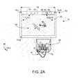
- FIG. 2Ais a front view of a portable device whose acquisition system includes at least two two-dimensional cameras, usable to recognize gestures, and showing a three-dimensional interaction region within a larger hover zone according to embodiments of the present invention
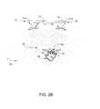
- FIG. 2Bis a top view of the portable device of FIG. 2A ;
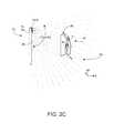
- FIG. 2Cis a side view of the portable device of FIG. 2A ;
- FIG. 3depicts multiple planes of an interaction region relative to a device screen display, and modes of user feedback, according to embodiments of the present invention
- FIG. 4Adepicts a mode of natural user gestures used to control imagery displayed by a device, according to embodiments of the present invention
- FIG. 4B and FIG. 4Cdepict a mode of user gesture to select and alter a portion of imagery displayed by a device, according to embodiments of the present invention
- FIG. 4D and FIG. 4Edepict a further mode of user gesture to alter size and orientation of imagery displayed by a device, according to embodiments of the present invention
- FIG. 4Fdepicts a further mode of user gesture to alter size and orientation of imagery displayed by a device, as well as a further mode of haptic user feedback, according to embodiments of the present invention
- FIG. 5is a flow chart depicting exemplary method steps in controlling haptic user feedback, according to embodiments of the present invention.
- FIG. 6is a block diagram of a generic two-dimensional camera as used to recognize gestures, according to embodiments of the present invention.
- FIG. 7Adepicts the relationship between world coordinates and local coordinates, according to embodiments of the present invention.
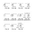
- FIG. 7B-FIG . 7 Gdepict use of epipolar-line camera system geometric properties to disambiguate multiple corresponding potential landmark candidates acquired by an acquisition system such as depicted in FIG. 2A , according to embodiments of the present invention
- FIG. 8A-FIG . 8 Kdepict latency improvements provided by embodiments of the present invention.
- FIG. 9is a block diagram of a two-camera device system, according to embodiments of the present invention.
- FIG. 10Ais a flow chart depicting exemplary method steps in detecting a fingertip landmark coordinates, according to embodiments of the present invention.
- FIG. 10Bis a flow chart depicting exemplary method steps in detecting a gestures and in sizing an appropriate subzone, according to embodiments of the present invention.
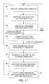
- FIG. 11is a flow chart depicting exemplary method steps for detecting a fingertip landmark using epipolar geometric analysis including image rectification, according to embodiments of the present invention.
- FIG. 12Adepicts the many process steps and associated high bandwidth data rate requirements associated with three dimensional sensing methods according to the prior art.
- FIG. 12Bdepicts the relatively fewer process steps and associated low bandwidth data rates to acquire three-dimensional coordinates for a relatively few landmark points, according to embodiments of the present invention.
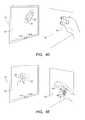
- FIG. 1A device 10includes a display screen 20 upon which is displayed imagery 30 (here a tennis player hitting a ball).
- imagery 30here a tennis player hitting a ball
- user 40can view and interact with the displayed imagery, preferably using three-dimensional gestures, perhaps using a hand. Interaction is detectable generally within a three-dimensional hover zone 50 , with actual detection at any given time occurring in a three-dimensional interaction subzone 60 that exists within the larger hover zone.
- FIG. 1A imagery 30is dynamic but it could instead be static, for example a menu bar or icons or selection buttons. In the example of FIG.
- user 40may play virtual tennis with the player and ball depicted on display screen 20 , by moving her hand or perhaps arm to simulate swinging a tennis racket.
- device 10might be smart TV, a home entertainment display, a computer, or more portable devices such as a laptop, a tablet, a smart e-book reader, perhaps a smart phone.
- Embodiments of the present inventionenable a user to sit or stand or perhaps recline a comfortable distance from device 10 , perhaps about 30 cm to about 80 cm, and make gestures that are reliably detected, identified and recognized by the device systems.
- Device 10includes an acquisition system 70 that enables the device to capture gestures made by user (or a user object) 40 intended to alter operation of device 10 and/or what is depicted on display screen 20 .
- userand “user object” are understood to include portions of a user, perhaps the head or face, a hand, a finger, a fingertip, perhaps a wand a user may choose to hold while gesturing.
- Detection of user interaction(s)occurs within interaction subzone 60 , which as noted exists within hover zone 50 .
- interaction subzone 60is a three-dimensional region, it is depicted as a single forward-most (e.g., closest to user) plane in FIGS. 1A and 1B , for ease of illustration. This while user interaction with device 10 can occur anywhere within hover zone 50 , the region of actual interaction is denoted as interaction subzone or sub-region 60 , and the plane of region 60 nearest to user 40 is denoted as plane z 0 .
- Acquisition system 70may include acoustical, and/or mechanical, and/or preferably, optical based gesture recognition and detection.
- Acquisition system 70preferably includes an optical system that acquires images of the user, which optical system may be, without limitation, a time-of-flight (TOF) system 71 , a structured light system 72 , a single two-dimensional camera 73 , or preferably at least a pair of two-dimensional cameras 74 -L, 74 -R, and optional 74 -B.
- TOFtime-of-flight
- system 70may also acquire user responses that do not involve gestures, and may include a gyroscope-accelerometer unit 75 .
- Output from unit 75can signal any tilting, shaking, and other physical manipulation of device 10 by the user to help communicate a user response.
- System 70may include a microphone 76 to detect user utterances, perhaps made in synchrony with gestures or made without gestures, intended to communicate responses to viewed happenings in the event being displayed, e.g., “left”, “right”, “open”, “close”.
- device 10may include an active light source 77 , for use in the event there is insufficient ambient illumination to acquire optical images suitable for reliable gesture processing.
- Acquisition system 70will further include a processor-controller system 78 to receive and process optical data from the device optical system, e.g., 71 , or 72 , or 73 , or 74 -L, 74 -R to detect and identify user gestures, and provide device 10 with appropriate command(s).
- processor-controller system 78can also process and interpret manipulation data output from gyroscope-accelerometer unit 75 , and verbal utterances and sounds from microphone 76 . Such additional information can be useful in interpreting other types of gestures.
- acquisition system 70optically detects gestures (and/or sounds and/or device movements) made by user 40 within interaction region 60 , a three-dimensional sub-region of hover zone 50 .
- acquisition system 70further includes a processor-controller system 78 having memory 80 storing software 82 , including algorithm routines 82 - 1 , 82 - 2 , . . . , 82 - n , and a processor block 110 executing such routine(s).
- the executed software routineprocesses and interprets these gestures (and sounds and/or device movements) for use by device 10 .
- Interpreted gesturesmay be used to alter operation of the device including perhaps altering imagery 30 depicted on display screen 20 and/or audible sound, perhaps volume level, emitted by the device. It will be appreciated that even if device 10 operated to present the user with audio but not with video, the user could still communicate via gestures and the like to the device.
- response of device 10 to user gesturesoccurs in real-time, or more practically in substantially real-time, by which it is understood to mean as fast as practicable, preferably within a second or two.
- embodiments of the present inventionthat do not require the user to gesture close to display screen 20 reduce user arm stress, especially the so-called gorilla arm syndrome, avoid smudging the display screen with fingerprints, and do not require to user or user-object to be in close proximity to the surface of display screen 20 to gesture.
- some devices 10include an acquisition system 70 comprising a TOF system 71 .
- TOF systemsare known in the art, and are described in numerous U.S. patents awarded to Canesta, Inc., formerly of Sunnyvale, Calif.
- Such TOF systemsemit active optical energy and determine distance (x,y,z) to a target object, e.g., user 40 by counting how long it takes for reflected-back emitted optical energy to be sensed, or by examining phase shift in the reflected-back emitted optical energy.
- Optical energy coming into the TOF systemfalls upon a sensor array of pixels, each of which produces a depth (z) signal and a brightness signal for the imaged scene.
- TOF systemsacquire true three-dimensional data without needing to triangulate to detect an (x,y,z) location of a target object, perhaps the user's right hand in FIG. 1A or FIG. 1B .
- TOF system 72should have an imaging range of at least a few meters. Consequently depth resolution must encompass a large zone volume but degrades substantially as a function of depth distance to user 40 .
- TOF system 71needs an imaging range of about 1 M, e.g., an arm's length.
- some portable devices 10may be placed on a stationery object, perhaps a desk, to capture user gestures, in which case an imaging range of perhaps 2 M or so would be needed.
- identifying a user's finger to recognize a gesture in an (x,y,z) hover zonerequires identifying as few as perhaps ten points.
- a TOF systemcannot simply provide three-dimensional data for ten points. Instead the TOF system must image the entire user target, which unfortunately generates a huge amount of raw data.
- a TOF system with a VGA-class sensor arrayacquires data from (640 ⁇ 480) or 307,200 (x,y) pixel array locations from which perhaps 80,000 to 300,000 (x,y,z) location points are produced.
- Such immense datarequires substantial processing, even though only perhaps ten data points are necessary to identify the needed (x,y,z) information.
- system 70with a TOF system 71
- TOF system 71there are substantial cost, package size, operating power, and processing overhead factors that tend to militate against using TOF systems.
- environmental factorssuch as high ambient light, system temperature, pixel blooming, electronic noise, and signal saturation can all affect the accuracy of the acquired (x,y,z) data.
- structured light systemsare known in the art and are described in a few U.S. patents issued to PrimeSense of Israel and are employed commercially in at least some models of the Kinect ⁇ device produced by Microsoft, Inc.
- a structured light systemilluminates the target object, e.g., a user, with a projected pattern of IR light.
- the projected light patternbecomes distorted on the surface of the target object, which typically is curved rather than planar.
- a camerathen images the distorted pattern of light on the target object surface and tries to discern from the distortion the shape and distance to the target object surface.
- structured light systemstend to be costly, physically large, and require substantial operating power.
- acquisition system 70could employ a single two-dimensional camera 73 to acquire user images made within the FOV of the camera.
- Such devices 10would be relatively inexpensive and have small form factor, and could recognize simple gestures made in a two-dimensional (x,y) plane. But absent reliable depth z-measurements, recognition of many gestures using a single two-dimensional camera would be constrained. Further error in identifying gestures would occur due to susceptibility to artifacts in the imaged background. User experience with such an acquisition system would be disappointing due to the high probability of misidentified gestures.
- Table 2enumerates the characteristics of the various implementations for acquisition system 70 employing three-dimensional sensing. Note the many advantages relating to low cost, small form factor, low power consumption, good performance in high ambient light realized by using two-dimensional cameras in acquisition system 70 .
- the 1 cm 3 volumerepresents two cameras and associated electronics. The 1 mm accuracy for such embodiments is achievable because such acquisition system is intensity and image processing based, with minimal electronic noise.
- the last row in Table 2notes that high levels of ambient light, e.g., sunlight, room light, are desired for a two-dimensional camera 74 -L, 74 -R acquisition system because more light can produce better acquired images. But with a TOF camera 71 acquisition system, high levels of ambient light can saturate the detector array with resultant degradation of acquired image data. With a structured light camera 72 acquisition system, high levels of ambient light can make it difficult to discern the projected pattern falling upon the target user, and thus degrade acquired image data. Data for a single two-dimensional camera is not presented in Table 2 due to difficulty in its reliably recognizing user gestures.
- ambient lighte.g., sunlight, room light
- device 10 in FIG. 1A or 1 Bmay include an acquisition system 70 using a TOF camera system 71 , or a structured light system 72 , or a single two-dimensional camera 73
- Table 2strongly favors using instead at least two two-dimensional cameras 74 -L, 74 -R. It is useful therefor to now describe in detail acquisition systems 70 that employ two-dimensional cameras 74 -L, 74 -R, etc.
- FIGS. 2A , 2 B, 2 Care respectively front, top, and side views of a portable device 10 whose acquisition system 70 includes at least two two-dimensional cameras 74 -L, 74 -R, and depict from different perspectives the three-dimensional sub-region interaction zone 60 .
- Zone 60may be thought of as a large number of parallel planes, one of which (plane z 0 ) is the first portion of zone 60 user or user object 40 interacts with.
- plane z 0the user's hand or finger(s) initially interaction with plane z 0 and upon moving forward toward device 10 (decreasing magnitude of z) will encounter other planes (not shown) within zone 60 .
- Plane z 0may but need not be defined parallel to the plane of display surface 20 .
- acquisition system 70 in device 10includes two-dimensional cameras 74 -L, 74 -R rigidly attached to the upper front region of the device, spaced-apart a distance W, although additional cameras could also be included, e.g., camera 74 -B.
- 74 -L, 74 -Rare a pair of generic two-dimensional inexpensive cameras that acquire two-dimensional image data from their two vantage points.
- OmniVisionsee www.ovt.com
- model OV7740 VGA two-dimensional camerasare a good choice for cameras 74 -L, 74 -R.
- This commercially available camerahas a horizontal FOV-H ⁇ 50° and vertical FOV-V ⁇ 40°.
- unit price of similar camerascan be less than $1.
- cameras 74 -L, 74 -Rare substantially identical with respect to their camera sensor array pixel resolution, sensor pixel wavelength sensitivity, and fields of view, however device 10 can be implemented in which the cameras are dissimilar in at least one of these characteristics.
- Distance W and angular orientation of the cameras with respect to each other and with respect to device 10 display screen surface 20are assumed to remain fixed within certain tolerances for the life of the device. Slight camera movements with respect to the device can be calibrated by the user or with auto-calibration methods.
- hover zone 50within which user gestures can be imaged by cameras 74 -L, 74 -R.
- its FOVwould define hover zone 50 .
- hover zone 50is shaded gray, for ease of understanding.
- interaction subzone 60is defined, and is the region of actual user interaction with device 10 at any given time.
- Cameras 74 -L, 74 -Rcapture two-dimensional images of at least a portion of user (or user-object) 40 within hover zone 50 , and more particularly within interaction zone 60 .
- cameras 74 -L, 74 -Rare spaced-apart distance W, at the top of device 10 , to provide overlapping field of view coverage.
- Dimension Wmight be on the order of perhaps 7′′ for a tablet-sized device, perhaps 2′′-7′′ for a pocket sized device such as a smart phone, and much larger for a smart TV type device.
- hover zone 50even a small distance W ⁇ 3′′ is commensurate with an effective 1 M depth for hover zone 50 , which is about an arm's length.
- a cross-section of hover zone 50 parallel to display surface 20will far, far exceed the magnitude of separation distance W, which promotes acceptably large hover zones even with when device 10 is a handheld pocket-size device, perhaps a smart phone.
- Cameras 74 -L, 74 -Racquire much image data, however only a relatively few landmark points are defined on key portions of the user or user object(s).
- software 82including several algorithm routines 82 - 1 , 82 - 2 , etc. stored in memory 80 processes incoming two-dimensional image data and intelligently creates three-dimensional image data by searching for so-called landmark points on the imaged objects.
- landmark pointsFor example in FIG. 2A , the letter A denotes a landmark point at the centroid of the user's right hand, letters B, C, D, E, F denote landmark points at the distal end, respectively, of the right thumb, forefinger, middle finger, ring finger, and little finger.
- Skeletal imagesare gesture data, e.g., a hand making a “V for victory” gesture, a hand with a pointing forefinger, a hand making a thumb-up or a thumb-down gesture, etc., stored in memory 80 associated with system 78 .
- the two-dimensional camera-captured imagesare examined by processor block 110 for skeletal gesture information to reconstruct (x,y,z) three-dimensional locations of the relatively few, e.g., perhaps less than a dozen, landmark points used to define a user gesture, e.g., points A, B, C, D, E, F in FIG. 2A .
- the various landmarksare identifiable objects, e.g., fingertip, nose, or here, specific finger tips and hand centroid, etc. that provide semantic clues that are relevant to successful implementation of natural user interfaces.
- gesturescan be captured in raw format that best describes location and motion of perceived user gestures, and flexibility exists in determining at what processing state a raw data capture should be interpreted as a high level command.
- High level commands and raw representationscan be described as a series of event names, event identification, and optionally can be associated with three-dimensional locations, and angle and velocity information.
- processor system 42preferably processes image data not for the entire scene but preferably only for a relatively few target object potential landmark points.
- Cameras 74 -L, 74 -R, etc.can operate cooperatively and independently albeit substantially simultaneously, under command of processor block 110 .
- Two-dimensional frames of image dataare captured substantially simultaneously by each camera from that camera's vantage point.
- the frames of image dataare coupled to processor block 110 at a known frame rate, typically 30 frames/sec., perhaps 60 frames/sec. if rapid user motion is anticipated.
- Cameras 74 -L, 74 -R, etc.are shutterable and typically employ a rolling or global shutter. If the cameras were perfect, exposures would start and end exactly simultaneously.
- substantially simultaneous operation of cameras 74 -L, 74 -R, etc.is understood to mean simultaneous within a tolerance ⁇ 1.5 ms or ⁇ 10% of camera exposure duration. Since generic two-dimensional cameras 74 -L, 74 -R may synchronize exposure relative to each other in sub-millisecond time, such tolerances are readily met.
- a user's handmay move rapidly at perhaps 100 mm/sec, which is a 0.1 mm movement in 1 ms, well within the tolerance for recognizing natural user interfaces.
- Motion blur during image acquisitionis reduced preferably by operating each camera 74 -L, 74 -R at a maximum gain, with commensurate shutter times, e.g., about 3 ms to about 5 ms.
- device 10includes optional active light source 77 , which may be toggled on and off synchronously with exposure captures made by cameras 74 -L, 74 -R, under control of processor block 110 to augment quality of captured images.
- cameras 74 -L, 74 -Rcan capture images using only ambient light, and then capture images using ambient light augmented by light source 77 .
- Processor block 110can subtract frames of optical data captured in these two modes to enhance capture of user-reflected optical energy by reducing clutter from images in the background behind the user.
- magnitude of light reflected by the usercan be used to estimate distance to the user, where exemplary skin reflectivity is known.
- Emissions from optical source 77preferably include spectra energy for which the pixel sensor arrays in cameras 74 -L, 74 -R are sensitive, e.g., visible light for RGB and monochrome cameras, and IR for cameras sensitive to IR energy.
- FIG. 2Bis a top view of what was depicted in FIG. 2A , and as shown the y-axis extends upward from the x-y plane.
- Depicted fields of vieware the horizontal fields of view (FOV-LH) for camera 74 -L, which preferably has the same field of view (FOV-RH) as camera 74 -R.
- Exemplary horizontal FOVswill typically be in a range of about 40° to about 60°.
- Interaction subzone 60is shown with the tip of the user's fingers beginning to intersect a front-most plane x 0 .
- FIG. 2Cis a side view of what was depicted in FIG. 2A .
- FOV-RVand FOV-LV for camera 74 -L
- each camerapreferably is tilted at a so-called vergence angle of perhaps 5° such that the optical axes are not parallel but rather slightly inclined toward each other, to attain a desired hover zone 50 , which can be made sufficiently large to image multiple objects simultaneously, perhaps a user's head and hand, useful in recognizing some gestures.
- FIG. 3depicts device 10 and display screen 20 whereon there is rendered a virtual keypad 30 , one of whose keys 30 ′ is depicted in bold as having been user-selected, and whereon there is also rendered a user-positionable cursor 30 ′′.
- FIG. 3also depicts interaction zone 60 generally within hover zone 50 , which is depicted as being an imaginary frustum.
- Frustum 50can be defined as bounded by upper plane 50 T, bottom plane 50 B, right plane 50 Rt, left plane 50 L, rear plane 50 R, and front plane 50 F.
- Right plane 50 Rt, left plane 50 L, upper plane 50 T, and bottom plane 50 Bare related to the FOV and focal point restrictions associated with the optics of the camera(s) used, e.g., 74 -L, 74 -R.
- Front plane 50 Fis drawn with thick lines solely to add in understanding the figure and exists as a restriction intentionally imposed by the software executed by device 10 , e.g., software 82 - n in FIG. 9 .
- Such softwaremay include thresholding z-distance from device 10 to intentionally exclude optically imaged irrelevant activities occurring farther from device 10 than user-object 40 .
- rear plane 50 Rmay be display screen 20 itself or another imaginary plane at certain distance (e.g., 10 cm) from the display screen, and will approximate the start of the overlapping FOVs of cameras 74 -L, 74 -R, etc.
- Planes 50 F, 62 , 62 ′, 62 ′′, 62 ′′may but need not be parallel to the plane of display screen 20 .
- a z 0 planeis not an ideal plane but rather a region that may be somewhat curved rather than strictly planar with a thickness, within which the user may comfortably make gestures.
- user 40can dynamically and relocatably define the interaction subzone 60 , interacting perhaps at position (x,y,z) in plane 62 , or perhaps interacting more to the right and closer to device 10 at position (x′′,y′′,z′′) in plane 62 ′′, etc.
- the effective interaction subzone in use during active gesture makingpreferably is smaller than the volume of the hover zone.
- the four corners of virtual plane 50 Fare referenced back to cameras 74 -L, 74 -R, whose FOVs determine the geometry of hover zone 50 .
- the four corners of a given interaction zone plane, e.g., 62are referenced back to the four corners of display screen 20 .
- a virtual mapping between the four corners of a subzone plane, e.g., 62 , to the corresponding four corners of display screen 20functionally couples the user-object fingertip to a hypothetical pointer location on the display screen, perhaps at the location of position cursor 30 ′.
- mappingis reestablished when subzone 60 dynamically relocates within hover zone 50 such that user-object interaction with a subzone plane, e.g., 62 , maps the user-object, e.g., forefinger 40 , (x,y,z) position in space to an (x,y) location on display screen 20 .
- software within system 78customizes position of interaction subzone 60 within hover zone 50 per user preference.
- interaction subzone 60preferably at least three interaction planes are defined: e.g., a front plane 62 ′ closest to the user, a rear plane 62 ′′ closest to the display screen, and an intermediate z 0 plane 62 ′′ roughly therebetween.
- cameras 74 -L, 74 -Rare disposed relatively close together at the bottom portion of device 10 , and their spaced-apart distance W is governed by the desired depth measurement resolution and the operating distance from display screen 20 to user/user-object 40 .
- Such camera displacement near the bottom of display screen 20allows the optics of the cameras 76 -L, 76 -R to readily image the user at a comfortable distance from device 10 , while also enabling imaging the user hand when brought relatively close to display screen 20 , perhaps when moved above a keyboard if device 10 is a laptop computer.
- system 78defines interaction subzone 60 within comfortable working distance of the device.
- the usere.g., user-object 40
- W r , H r and D r designationsare shown for an alternative interaction subzone although similar measurements are also applicable to interaction subzone 60 .
- the usercan point forefinger 40 into hover zone 50 until device 10 system 78 detects interaction with a z 0 plane, perhaps 62 . Detection of this start of interaction can be feedback to the user by way of visual feedback, perhaps creating and display an expanding bulls-eye target 32 , or by highlighting or color changing or resizing virtual key 30 ′, or by generating acoustic feedback 34 . (As described with reference to FIG. 4F , haptic feedback may also be used.) In such fashion the user knows when interaction with a z 0 plane is ongoing, and can maneuver the forefinger within this plane to interact with device 10 .
- activity on display screen 20can follow, perhaps repositioning cursor 30 ′′ from say screen top left to screen bottom right as the user's forefinger moves from top left to bottom right in the z 0 plane.
- Spatial magnification or contraction between user-object movements in a z 0 plane and resultant movement perhaps of cursor 30 ′′ on display screen 20is accomplished as follows.
- display widthbe W s and display height be H s (perhaps defined in pixels) with a given pixel/inch density
- interaction subzone 60be sized perhaps W r 20 cm wide by H r 15 cm high
- H srbe defined as W s /W r .
- user-object 40(a user's forefinger) is shown interacting at this time with a closer-to-user z 0 plane 62 , at point (x,y,z).
- a closer-to-user z 0 plane 62at point (x,y,z).
- the usermight have instead first interacted with device 10 by moving forefinger 40 to the right and forward to interact with a z 0 ′′ plane 62 ′′ at point (x′′,y′′,z′′).
- the userintends to virtually select the top right key 30 ′ in virtual keypad 30 on display screen 20 .
- processor block 110 within device 10can determine whether a latch-to-displayed target event has occurred. Appropriate feedback can then be generated, perhaps by highlighting virtual key 30 ′ (drawn in bold to indicate selection recognition and highlight). In other applications system 78 might generate other relevant feedback to the user upon gesture detection, perhaps visual feedback such as an expanding bulls-eye image 32 , and/or creating acoustic feedback, indicated by 34 .
- GUI feedbackmight be presented to the user in the manner of ripples of water emanating from a tossed stone rather than the simple expanding bulls-eye target suggested by feedback image 32 .
- the shape of cursor icon 30 ′′might be changed when three-dimensional gesture is sensed, or a gesture-indicated image region (perhaps 30 ′) on display 20 can be highlighted, bolded, outlined, etc. to confirm to the user that device 10 recognition that it is now in gesture mode.
- system 78can cause device 10 to correspond accordingly.
- device 10has telephone functions such as a smart phone, a phone icon may be displayed.
- system 78 in device 10can intelligently automatically enter a loud speaker mode on the presumption the user is probably at some distance from the device and at this instant cannot interact with the z 0 plane.
- Executed software within system 78determines what gesture including natural user interface gesture is being made, and causes device 10 to react according, commensurate with the device interpretation of the user's intent in making the detected gesture.
- the user-object(forefinger 40 ) is used to initiate device 10 that a gesture is about to occur.
- an interaction subzone 60is established by perhaps the user holding user-object 40 for a few moments or moving it sideways (as shown in FIG. 4A ), or even performing a poking action.
- system 78 recognition of the initiation gestureupon device 10 system 78 recognition of the initiation gesture, the system is ready for more typical gestures, perhaps navigation or selection of objects displayed on display screen 20 .
- system 78recognizes that an interaction is now incurring in plane z 0 within interaction subzone 60 , at least two types of information are recognizable.
- system 78recognizes user intent by parsing the optical data acquired, e.g., by cameras 74 -L, 74 -R, to understand information as to the type of gesture and where in (x,y,z) space the gesture has occurred.
- system 78knows implicitly that by interacting with plane z 0 user 40 has elected to communicate with device 10 using a gesture rather than with perhaps available for user input any keyboard, mouse, or touchscreen. The user may be too distance from device 10 to conveniently use a keyboard, mouse, or touchscreen.
- system 78can dynamically customize and optimize the response of device 10 to the user interaction. For example, if the depth z from display screen 20 to plane z 0 is relatively large, image presented on display 20 can be automatically enlarged to take into account the greater distance to the user's eyes, etc.
- Embodiments of the present inventionallow user-object 40 interaction with zone 60 to be readily made from a comfortable position.
- Finger user-object detection by device 10 system 78is preferably carried out by detecting the shape of the object (a finger) and the nature of the object motion within interaction zone 60 .
- the following descriptionprovides examples of some user-device interactions.
- rectangle-plane 62 ′′is dynamically relocatable within interaction subzone 60 , and can be at the position shown for plane 62 , or perhaps 62 ′, or 62 ′′, among an infinite number of other positions.
- An advantage to defining and then limiting user-object 40 interaction to rectangle-plane 62 ′′is that potential user-object interactions elsewhere within larger hover zone 50 may be ignored by device 10 system 78 . So doing reduces the likelihood of false detections of unintended user responses by device 10 , a problem that occurs often with prior art approaches.
- FIG. 4Adepicts an exemplary use of acquired gestures by device 10 made by a user-object forefinger 40 interacting at (x,y,z) with a z 0 plane in interaction subzone 60 , according to embodiments of the present invention.
- display screen 20 associated with device 10displays imagery 30 , here comprising a movable section of a globe with an up-down slider to adjust image size and a compass rose to move the globe section north, east, south, west.
- This imagery 30may be a map website or perhaps an application executed by device 10 .
- a ribbon menu 32 ′′presenting user-selectable (via gesture(s)) choices is caused to appear, and also to provide visual feedback to the user confirming the gesture just made.
- the user's selecting a choice presented in ribbon menu 32 ′′may invoke additional user aides, perhaps the appearance on the display screen of navigation keys 32 , which again provides visual feedback to the user, confirming the gesture.
- navigation keys 32can be used with user-object 40 interaction within the z 0 plane, perhaps to give finer control over repositioning and zooming of globe object 30 than available with the native rose compass and slider bar.
- navigation keys 32might be used as virtual keyboard cursor keys, by the user's pointing in three-dimensional space with forefinger 40 in the z 0 plane.
- ribbon menu 32 ′′might give the user additional options, perhaps offering text attributes in a word processing application, perhaps offering hue control in a photo-editing application, etc.
- the various user gestures invoking either changes in the preexisting imagery 30 , perhaps rotating and/or zooming on a globe region, or in invoking the appearance additional control over device 10 and/or imagery 30are recognized and processed by system 78 , device 10 .
- Displayed imagery, e.g., any or all of 32 , 32 ′′, and 30 ′′depends upon the graphic user interface (GUI) application being used by device 10 .
- GUIgraphic user interface
- direction keys 32might move a typing cursor
- ribbon menu 32 ′′might present further options, perhaps font choices and font attributes.
- arrow keys 32may be used to control displayed icons.
- the usercan interact with the displayed arrow keys 32 , with ribbon menu 32 ′′ choices by pointing to desired arrow key(s) and/or ribbon menu choice(s) in (x,y,z) space in the z 0 plane using the user's forefinger.
- FIG. 4Aalso depicts a maximum interaction angle ⁇ , when viewed from above, defined between a leftmost and rightmost rotation of about 45° of the user's forefinger with the wrist held stationary. This rotation can result in an intersection zone 60 dimension at display screen 20 of about 1.25 times display screen width W s for large display screens 20 . This inherent scaling advantageously enables the user with an easily made movement of the forefinger to interact with more of display screen 20 .
- cursor 30 ′′is also moved left, right, up, down, with a velocity that can be (but need not be) commensurate with real-time movement of the user-object.
- a displayed object other than a cursorcould be similarly moved using such gesture.
- Such direction and velocity scalingis a function of software within device 10 system 78 . Scaling and magnitude of the movement may be linear or non-linear, large or small, depending upon software implementation associated with system 78 in device 10 . In reality, the user cannot generally draw perfect virtual circles or perfectly straight lines when using the forefinger to draw or manipulate object images on display screen 20 .
- embodiments of the present inventionprovide software, e.g., 82 - n in memory 80 in system 78 within device 10 to smooth out such human imperfections during user interactions with device 10 .
- imagery 30 presented on device 10 display screen 20is shown as icons denoted A, B, C, . . . R. These icons need not be keys on a virtual keyboard but can represent discrete images, menu buttons, tiles, etc.
- the “A” iconmight be a “weather” icon
- the “B” iconmight be a website favorites icon
- the “C” iconmight be a “contact list”, etc.
- User-object 40interacts with the z 0 plane and can select an individual icon, perhaps the “J” icon, and can cause this region of the originally displayed icons to become enlarged, as shown in FIG. 4C .
- Device 10provides feedback that the use has selected the “J” icon by highlighting or perhaps enlarging the perimeter 30 ′′.
- the iconcan be progressively highlighted commensurate with the direction of user-object motion, thus signifying that the selection is about to move the icon in the direction of the user-object motion.
- the usermay in some embodiments confirm selection by moving the user-object (forefinger) rapidly in and back out of the z 0 plane, although other types of user confirmation movements could instead be used. Accordingly in FIG. 4C , the portion of the original display centered about the “J” icon now appears enlarged.
- FIG. 4Ddepicts the user employing right thumb and right forefinger in the z 0 plane to expand (or optionally contract) the ellipse 30 image displayed on monitor screen 20 to the enlarged version shown in phantom as 30 ′. Enlargement results from the user moving thumb and forefinger apart in the interaction zone until image 30 ′ reaches a desired size. Alternatively, the thumb and forefinger could be moved closer together to contract the displayed size of ellipse 30 .
- FIG. 4Eshows display screen 20 presenting the image of a flower 30 that user-object 40 interacting with the interaction zone can cause to rotate, here clockwise as suggested by the arced arrow.
- the usercan point to the flower image with the forefinger and to indicate to device 10 that this is the object to be selected, the user can close the remaining three fingers towards the palm, as shown in FIG. 4E . Having thus virtually attached the forefinger to the flower, the user can rotate the forefinger clockwise as indicated by the phantom hand in FIG. 4E . The result is that device 10 causes the displayed image to now rotate and appear as image 30 ′ on display screen 20 .
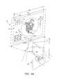
- FIG. 4Fdepicts an embodiment in which the user-object 40 can virtually grab and manipulate in (x,y,z) space in the interaction zone a two-dimensional representation of a three-dimensional object 30 presented on display screen 20 , here a cube.
- the userwill virtually engage at least a face of cube object 30 to initiate the gesture.
- device 10 system 78sends the (x,y,z) real-world position of the user's thumb and two fingers in real-world coordinates to the software application manipulating cube object 30 .
- the applicationmaps the three points (indicated by +'s by the user's hand) to three hot spots on the face of the cube, which hot spots are depicts as small circles.
- a logical connectionis now present between the user's physical thumb and two fingers, and the three hot spots on the virtual cube display, as if the user were physically holding the virtual cube at the three hot spots.
- the virtual cubeis commensurately manipulated in virtual space.
- FIG. 4Fthe user has rotated the cube and has also resized it somewhat, as depicted by image 30 ′ on display screen 20 .
- the usercan detach the hand from the virtual object, perhaps to virtually throw the object.
- a “let go of object” gesturecan be defined in several ways, e.g., the user rapidly bring the thumb and two fingers together or rapidly shaking the hand.
- FIG. 4Fdepicts a mode of haptic feedback 90 ′ to the user, who wears a vibratory ring 90 .
- a wireless unit 88 in device 10can transmit via WiFi, BlueTooth, etc. (indicated by zig-zag lines), a signal to command ring 90 to vibrate (indicated by 90 ′).
- Ring 90would include an appropriate receiver, a responder, and a battery.
- haptic feedbackcan augment or replace visual feedback 32 and/or acoustic feedback 34 as shown in FIG. 3 .
- FIG. 5depicts exemplary method steps, carried out by device 10 system 78 to recognize user gestures and to trigger feedback, according to embodiments of the present invention. It is understood, however, that feedback other than haptic (e.g., acoustic feedback, visual feedback, could be created in a similar fashion as described for FIG. 5 .
- software within system 78is executed to set the parameters governing the present size of interaction zone 60 .
- a next frame of dataoptically gathered by cameras 74 -L, 74 -R (see FIG. 9 ) is examined by system 78 to detect the possible present of a user-object.
- step 220if a user object is not yet detected, any on-going feedback including haptic feedback is halted. But if object-detection appears to be occurring at step 240 feedback including haptic feedback is commenced.
- commandsare issued to unit 88 to transmit signals commanding ring 90 to vibrate. (If acoustic and/or audible feedback is employed as shown in FIG. 3 , proper commands are issued to device 10 to generate appropriate display and/or acoustic signals.)
- a second mode of vibrationcan be commanded (perhaps change in repetition rate, and/or intensity, and/or vibratory pattern) to confirm to the user that the user-object is remaining within the user interaction subzone.
- step 255three-dimensional gesture recognition within device 10 system 78 occurs as processor block 110 executed algorithms 82 - n stored in memory 80 to carry out image processing, computer vision, and/or machine learning.
- a coded vibratory (or visual and/or acoustic) signalcan be commanded, based upon the user interaction as a function of time during the gesture.
- the routinebranches back to step 210 where the process is repeated for a next frame of optical data, and so forth.
- FIG. 6depicts an exemplary two-dimensional camera 74 -L and an object 40 , a user's face showing additional exemplary landmark points: nose G, eyes H, I, mouth K.
- Camera 74 -Lpreferably includes a shutterable lens 90 having a lens optical axis 90 ′, optional filters 92 , 92 ′, an image plane comprising a planar array 94 of sensor pixels p (x,y) arranged in rows and columns.
- Each such camerapreferably further includes optional processor/controller 96 , control and communication interface circuitry 97 , and optional in-camera memory 98 , which may include volatile and non-volatile memory.
- Non-volatile memorycan store camera calibration and other configuration data, while volatile memory can support processor programming and store temporary runtime data.
- sensor array 194may be a relatively high resolution RGB (color), or gray-scale sensor array, or even an IR sensor array.
- array 94is fabricated using CCD or CMOS processes. Density of pixels p (x,y) in each camera's sensory array depends upon several factors including the smallest gesture movement made with a pointing finger that must be detected, the vertical FOV-V and horizontal FOV-H camera fields of view, and image frame size to be acquired and processed.
- the earlier-noted OmniVision model OV7740 VGA two-dimensional camerahas a sensor array with pixel density 480 h ⁇ 640 v, which is adequate for gesture recognition, according to embodiments of the present invention. If cameras 74 -L, 74 -R, etc.
- RGBpreferably integrated color filters 92 are employed, arranged in a so-called Bayer pattern over the pixels on a per-pixel basis.
- device 10includes an IR emitter source, e.g., source 98 , and camera sensor pixel arrays 94 can detect IR, at least one of filter 92 and 92 ′ can be an IR bandpass filter to eliminate user objects illuminated by ambient rather than IR optical energy.
- IR emitter sourcee.g., source 98
- camera sensor pixel arrays 94can detect IR
- filter 92 and 92 ′can be an IR bandpass filter to eliminate user objects illuminated by ambient rather than IR optical energy.
- the various cameras 74 -L, 74 -R, etc. in the camera grid for device 10need not have identical pixel resolutions, sensor array wavelength sensitivities, etc.
- Camera processors/controllers 96can also be used to provide such relatively minimal color and exposure correction as may be desirable to detect user gestures and the like, perhaps to discern skin color from other color. While FIG. 6 shows lens 90 and sensory array 94 as being centered on a common optical axis 90 ′, in practice a slight offset may be present. Nonetheless symmetrical lenses 90 may still be used, as embodiments of the present invention can handle optical distortion associated with generic inexpensive cameras 74 -L, 74 -R, etc.
- Successful gesture recognition by device 10is promoted by knowing or obtaining intrinsic (or geometric) parameters, extrinsic device parameters, and camera registration with respect to each other and with respect to device 10 .
- this informationis acquired during one or more calibration steps.
- the intrinsic or geometric parameters of each camerae.g., 74 -L
- the intrinsic or geometric parameters of each camerawill have been determined, including camera lens focal length, horizontal and vertical pitch of pixels p (x,y) in array 94 , FOV-H, FOV-V, and optical distortion parameters k i .
- calibration parameters for each camera 74 -L, 74 -R, etc.preferably are determined and thereafter known a priori and are stored in camera memory 98 or in memory 80 associated with processor block 110 .
- Processor block 110uses these stored camera parameters (as well as stored device 10 parameters) during device runtime operation to correct or at least reduce errors including camera distortion. Such correction justifies processor block 110 analysis in which cameras 74 -L, 74 -R are treated as being ideal pinhole cameras. So-doing enables use of extrinsic parameters, e.g., R and T parameters (described later herein) to correctly reconstruct three-dimensional (x w ,y w ,z w ) positional coordinates for any landmark acquired by device 10 relative to a device-mounted camera, e.g., 74 -L, and relative to a global coordinate system, e.g., relative to a fixed reference.
- extrinsic parameterse.g., R and T parameters (described later herein) to correctly reconstruct three-dimensional (x w ,y w ,z w ) positional coordinates for any landmark acquired by device 10 relative to a device-mounted camera, e.g., 74 -L,
- each camerais deemed equivalent to a ray-based optic device that projects rays of incoming light via the camera lens 90 , 150 ′ to pixels on its sensor array 94 , where the three-dimensional cone of such rays define the camera FOV
- Intrinsic calibrationdetermines correct mapping between the rays and pixels in the sensor array for each camera. Once the camera is calibrated, the forward projection from a ray of light to a pixel in the sensor array, and a backward projection from a pixel to the ray of light are known. After the cameras are fixedly mounted to device 10 , extrinsic system calibration determines each camera's extrinsic properties.
- extrinsic propertiesinclude the two-dimensional pixel coordinates p (x,y) of each camera's sensor array 94 , with respect to the outside world. These extrinsic properties further include each camera's rotation and translation matrices, respectively R and T, with respect to the (x w , y w , Z w ) external world common coordinate system associated with device 10 (see FIG. 9 ). Such a priori knowledge of the collective geometric properties of the cameras 74 -L, 74 -R, etc. and device 10 can be used to locate landmark positions for user-objects 40 in three-dimensional interaction subzone 60 .
- calibrationdoes not require knowledge of the camera orientation, and starts by defining a camera reference system that need not be accessible external to the camera. That is, one cannot readily measure location of a real world object with respect to that reference coordinates until calibration is completed and the camera is registered to an external world coordinates.
- Such approachis a convenient mathematical concept to derive camera calibration parameters.
- Corner milestones in the patternare identified with sub-pixel resolution in the camera pixel sensor image plane. Calibration precision is enhanced by repeating this measurement several times, with different pattern images. Correspondences between the landmarks and their respective (sub)pixel locations in the image plane are input to a cost-minimizing calibration algorithm, e.g., 82 - 1 , 82 - 2 , etc. stored in memory 80 within processor block 110 (see FIG. 9 ).
- the processed outputincludes the set of intrinsic parameters for the camera, preferably stored, e.g., within camera memory 98 ( FIG. 6 ), or memory 80 ( FIG. 9 ).
- Calibrating camera intrinsic and extrinsic propertiesis typically done once in the lifetime of a camera. Acquired calibration data should be valid for the life of the camera absent significant positional shifts inside the camera, and between mounted cameras relative to each other and to device 10 . One might, however, develop procedures to regenerate such data after the camera has been mass produced. But in practice, gathering and storing the various calibration information is preferably done during manufacture of the cameras and/or device 10 . So doing further conserves device 10 processing power, as does processing with the cameras of time-invariant calculations. Calibration precision is a function of how well calibration mapping can be estimated, and the quality of calibration should be commensurate with the precision requirements of the application. For example, recognition of gestural interfaces does not require the mm or sub-mm metrology demanded by touch screen specifications.
- the stored calibration and registration informationcan be used for many purposes.
- information from the camerascan be correlated.
- a landmark, perhaps right forefinger tip C in FIG. 2A-FIG . 2 C, imaged by camera 74 -Lcan be said to lie in an epipolar line from another camera, 74 -R.
- the landmark, here C, for object 40is detected in the image planes of at least two cameras, e.g., 74 -L, 74 -R, the corresponding backward projection rays can be intersected to determine the three-dimensional position of the landmark in the global world coordinate system (see FIG. 6A ).
- Preferably dense stereoscopically acquired depth calculationsare carried out using the sum of squared differences (SSD) method in which a window (or kernel) having a width and a height is assumed.
- SSDsum of squared differences
- each camera74 -R, 74 -L, etc. captures on the camera's image plane 94 - 1 , 94 - 2 an image of an object in the hover zone. If each camera images at least part of the same object, the object will appear on each image plane. Relative shift in location on the two image planes of a commonly imaged object is termed disparity, which disparity diminishes as the distance from the camera to the object increases.
- the kernel or window widthmay be as large as the maximum disparity between two corresponding object image points.
- the window heightmay be as large as what calibration tolerance for device 10 dictates, perhaps 10 pixels.
- cameras 74 -R, 74 -Lhave a spaced-apart baseline W of 6 cm (see FIG. 2A ), and a lens 150 focal length of 1.6 mm. If device 10 had to compute depth ranging from about 12 cm to infinity, then maximum disparity size for two corresponding points in each image would be about 0.8 mm, i.e., (1.6 mm) ⁇ (6 cm)/(12 cm) or 0.8 mm. If pixel density or pitch on array 94 is 2 ⁇ m, then the number of pixels to be analyzed for possible correspondence matches may be up to 400 pixels.
- Device 10preferably avoids having to cope with such large amounts of data by intelligently identifying a relatively few so-called relevant landmark points in two-dimensional camera-acquired image data. Three-dimensional reconstruction of locations of these relatively few points is undertaken, with no reconstruction being taken for all data points. The culling out of unnecessary data points reduces three-dimensional reconstruction very substantially, eliminating perhaps 99.9% of the data points.
- Preferably application of justified epipolar geometry and image rectification techniques during signal processingsubstantially reduce time and latency needed to arrive at a final, very sparse, set of landmark points used to identify user gestures. Such techniques promote rapid real-time performance for overall device 10 , according to embodiments of the present invention.
- processor system xx92(see FIG. 9 ) preferably includes relevant task partitioning and communication logic functionality.
- the software algorithms preferably used by embodiments of the present inventionwill now be described generally at a logical level and with reference to some of the many opportunities for potential parallelism of algorithm steps (or blocks).
- data processing within device 10seeks to rapidly extract a relatively few relevant (x,y,z) landmark points from (x,y) data obtained by acquisition system 70 , without having to extract a lot of unnecessary (x,y,z) data.
- two-dimensional image recognitionis carried out on the acquired (x,y) image data to locate landmarks associated with the imaged object(s) in so-called image coordinates.
- These coordinatescan be pixel or sub-pixel p (x,y) addresses in each camera's sensor array 94 for objects of interest, e.g., fingertips, hand centroid, medial axis of fingers, etc.
- Processing system softwarepreferably labels each landmark using an identification rule.
- Each camera's a priori determined and stored lens distortion and other camera intrinsic parametersare used to find the undistorted image coordinates of the landmarks on a per camera basis.
- a likelihood priority order of the correspondence between the landmarks across different camerasis then employed, e.g., a given index fingertip acquired in this image from camera 74 -R is most likely the same as the index fingertip in the other image acquired by camera 74 -L, etc.
- Advantageous use of so-called epipolar scan lines and image rectificationassists in rapidly disambiguating potential landmark points, to quickly find the best matches.
- the (x,y,z) coordinates for each landmarkare determined with respect to coordinates of each camera, subject to a scale factor.
- the scale factorrepresents the assumption that the real-world position of a landmark in image coordinates (i.e. a pixel or sub-pixel address) is along a given light ray associated with that pixel or sub-pixel, subject to some error in the image analysis and calibration process. If camera calibration information has not been provided by the camera manufacturer, such information will be generated and stored by the manufacturer of device 10 . Light rays are depicted in FIGS. 1A , 1 B, 2 A- 2 C and FIG. 9 as spoke-like lines emanating outward from each camera to define the relevant FOV. FIG.
- FIG. 7Adepicts for a generic two-dimensional camera such as 74 -L the relationship between an object 40 (or L), a light ray (drawn in bold) from the object, passing through camera lenses 90 ′, 90 , to image plane 94 , and the camera's virtual image plane 94 ′.
- the (x,y,z) camera coordinates of each landmarkare converted to (x w ,y w ,z w ) common world coordinates, using previously determined and stored device 10 extrinsic parameters.
- three-dimensional reconstruction of corresponding landmarks across the camerasis carried out using at least one minimization algorithm.
- the taskis to find the three-dimensional intersection of at least two rays in three dimensions.
- the first of the two raysis from a landmark point to the pixel sensor on camera 74 -L
- the second rayis from the same landmark point (but as viewed from the second view point) to the pixel sensor on camera 74 -R.
- various error factorscause the two rays to come very close to each other near the landmark point, but not intersect perfectly mathematically.
- embodiments of the present inventionuse a minimization algorithm to find the midpoint of two closest points in the two rays corresponding to the same (or substantially nearly the same) landmark.
- correspondences of unlikely pairsare cleaned-up preferably based on heuristics or information from the past correspondences or tracking predictions, e.g., using a common filter based upon probabilities, perhaps using known Markov prediction or Bayesian networks methods.
- the algorithmthen preferably performs smoothing and tracking in the world coordinates, and user interface events including gestures are produced with location information with respect to (x w ,y w ,z w ) common world coordinates.
- Various compression methodsmay be used for cameras 74 -L, 74 -R having higher pixel density sensor arrays 94 ( FIG. 6 ).
- semantic compressionpreferably sends onward only segments of the acquired image that are of interest for the relevant application.
- a semantic compressionis one that understands the image, e.g., if the object is known to be a hand, the processor can reduce the data to be transferred to only those pixel addresses representing a few fingertip points, or other key landmarks for a gesture application.
- the processormay reduce the volume of data transfer by reducing the image to a few pixels representing a few landmark points, perhaps the contour of a user's hand, and their properties, or even perform some rudimentary gesture processing.
- a relatively few landmark pointsmight be fingertip points relating to the tip of at least one user finger or other object, used in a gesture application.
- Segmentationinvolves labeling pixels that are part of the acquired image foreground and presumably the user of interest, which is to say that segmentation seeks to find these key parts in the camera-acquired images. For instance, for a user hand object, segmentation labels pixels that are part of the hand and wrist, palm and fingers. If two hands are imaged, segmentation can identify up to ten finger parts, e.g., landmarks, and the result of the segmentation process from each camera is thus an image that has unique labels for each finger, palm and wrist, e.g., an image of the relevant landmarks A, B, C, D, E, F in FIG. 2A , 2 B, 2 C.
- Such image of the relevant landmarkscan be represented more compactly and thus require less bandwidth and less memory storage than if the entire frame of acquired imagery were processed and stored.
- the segmentation algorithmcan run in parallel for the image acquired by each camera, and if the camera includes a processor, e.g., 96 in FIG. 6 , each such processor can perform segmentation on each image.
- processor block 110 in acquisition system 78can schedule parallel threads to perform the multiple segmentation tasks simultaneously. Segmentation and use of probable landmarks before the three-dimensional data is reconstructed further enable implementation of device 10 using inexpensive, generic components, unlike many prior art approaches.
- Image segmentation algorithmsare known in the art. Some algorithms make assumptions as to object shapes, e.g., a finger is a cylinder that begins with a tip and ends when it joins a wider body of pixels representing the palm of the hand object. If the cameras acquire color information, the algorithm can use color features to assist in segmentation. Other algorithms store hand model data, and then try to match a camera-acquired image of an object to see which stored model provides the best object match. If the model matching is reasonably acceptable, other image parts can be readily determined since they are already identified in the model. From the perspective of the left camera 74 -L a finger object 40 can be occluded by the other fingers, yet still be visible to another camera 74 -R because of the differing vantage point.
- FIG. 7Adepicts concepts used in defining a global system of coordinates, according to embodiments of the present invention, although an intuitively identifiable coordinate system is not necessary for implementing all types of natural interface applications.
- a global system coordinate systemis useful and can be defined with respect to a known world point (e.g., a known location on device 10 ).
- FIG. 7Adepicts the role of geometric properties of a pin-hole camera, each camera, e.g., idealized 74 -L, 74 -R, etc., and depicts a camera image plane 94 , and a virtual image plane 94 ′ defined by coordinate axes (x,y) equivalent to (x c ,y c ).
- camera lens 150is midway between image plane 94 and virtual image plane 94 ′.
- Tracking the motion of a gesturerequires accurately locating the position of the hand making the gesture in three-dimensions with respect to world coordinates. So doing can be particularly important in tracking dynamic gestures, and gestures that mimic the behavior of a computer mouse.
- the geometric concepts in the following derivationrefer to a single camera, the derivation is applicable to any number of cameras, e.g., 74 -L, 74 -R.
- FIG. 7Adepicts a user or user object 60 at location L, and also shows the camera sensor array 94 of pixels p (x,y) .
- FIG. 7Aassumes a camera with an ideal lens model, however lenses of actual cameras often have often have distortion. The following analysis demonstrates how lens distortion can be removed or compensated for, such that the ideal model described below is applicable to the actual camera.
- Lens 90will be equidistant between array 94 and a virtual image plane 94 ′, drawn with phantom lines. A single ray (of many rays) within the FOV of the camera sensor array and lens is drawn with a bold line (for ease of understanding) terminating at point L, object 40 . It is understood that FIG. 1A-FIG .
- FIG. 2 Cdepict a plurality of converging rays, of which the ray in FIG. 6A is but one such ray passing through point L.
- Each camerae.g., 74 -R, will image the landmark in different (sub) pixels of its array 94 , depending on its vantage point with respect to the user object of interest.
- Use of camera calibration and global registration informationenables calculating rays emanating from each camera that pass through L.
- the intersection of the rays from at least two camerasdefines the location of L in three-dimensional space in the active area.
- the raysdo not intersect due to slight offsets resulting from calibration error, the error introduced due to the vantage point of each camera, quantization and detection errors, etc.
- the parameters u 0 and v 0are the center of the image, and parameters ⁇ , ⁇ , c, u 0 and v o are obtained from the calibration step of each camera.
- Cameras 74 -L, 74 -R as used with device 10may have relatively large FOVs such that distortion effects cannot be ignored and lens correction is called for.
- Camera lens distortionhas a dominant radial factor and a less dominant tangential factor.
- Parameters k 1 , k 2 , . . .are lens distortion parameters and are estimated from the calibration step for each camera module.
- ( x n x n )may include iterative or other numerical methods that are available in the literature.
- ⁇ ⁇ X w Y w Z w ⁇be the coordinate of the landmark in world coordinates.
- FIG. 7Adepicts camera coordinates (X c , Y c , Z c ) and world coordinates (X w , Y w , Z w ) for a single camera, e.g., 74 -L, 74 -R. Similarly, each other camera has its own camera coordinates but shares the same world coordinate system, which is not shown in FIG. 7A .
- Focal length fcan be obtained from the lens specification or from the camera calibration process.
- the camera modelyields the following relationship:
- L⁇ x w y w z w ⁇ be the common world coordinate of point L in a common world coordinate system.
- the image imprint of the object in each cameracan be very different because the cameras view the object from different vantage points and from different distances. For instance, a user finger can fill the frame of a nearby camera but only occupy a small part of the frame of a distant camera. However when the user object is a comfortable distance from each camera, perhaps about 30 cm to about 80 cm, occlusion difficulties are lessened and substantial benefits can be obtained from the multiple views that are obtained to recognize landmark(s). If the user object is very far from the cameras, occlusion problems are less of an issue.
- cameras 74 -L, 74 -R, etc.will have been calibrated (and preferably calibration data stored in the camera's internal memory 98 ( FIG. 9 ) and modeled to have pinhole camera characteristics.
- Such characteristicsenable epipolar geometric analysis, which facilitates more rapid disambiguation among potential landmark points during three-dimensional reconstruction.
- image rectificationis used to make epipolar lines parallel to an axis of the camera image planes, to better facilitate finding correspondence between landmark image points acquired by the two cameras.
- software within the device processor systemlooks at epipolar lines drawn through landmark points in the first image plane to find candidate landmark points on or adjacent the epipolar line in the second image plane.
- FIG. 7B and FIG. 7Cdepict the application of epipolar line geometric properties of device 10 and cameras 74 -L, 74 -R according to embodiments of the present invention. These embodiments promote low processing requirements and improve latency times for overall device 10 by recognizing and taking advantage of these epipolar properties to enhance disambiguation between multiple potential object landmarks during three-dimensional reconstruction.
- Epipolar geometryis typically defined by assuming a pinhole camera model. Cameras 74 -L, 74 -R preferably are calibrated and registered with respect to each other.
- Registrationmaps the lens coordinate system of cameras 74 -L, 74 -R, etc. to a common coordinate system, e.g., a corner of device 10 , perhaps the center of the baseline distance W separating the two cameras, etc.
- the associated calibration informationenables each camera to be converted operationally so as to satisfy the characteristics of a pinhole camera. So doing entails determining the distortion model for cameras 74 -L, 74 -R, un-distorting camera-acquired images, and then finding camera intrinsic parameter values.
- distortionmay be nil, in which case un-distorting method steps may be dispensed with.
- This informationis saved, e.g., in memory 80 (see FIG. 9 ) or in in-camera memory 98 (see FIG. 6 ), for use during device 10 run-time operation.
- cameras 72 -L, 72 -Rcan be modeled as pinhole cameras and registered to each other, the properties of epipolar geometry can be advantageously employed to reduce processing search time to find landmarks (e.g., A, B, C, D, etc., see FIG. 2A ) acquired by device 10 .
- the present inventionseeks to recognize the user gesture and certain other gesture properties that are useful to implement a natural gesture-based user interface.
- gesture recognitionis a well-studied topic in the art, and aspects of the present invention provide a platform to implement gesture recognition algorithms.
- An exemplary result of a gesture recognition algorithm(e.g., perhaps routine 82 - 2 stored in memory 80 , FIG. 9 ) is a series of landmark points, e.g., fingertips, digits, palm centroid, wrist centroid, that define the configuration of the gestures.
- exemplary landmarksare denoted as circles on the display-facing surface of the user, e.g., A, B, C, D, E, etc.
- Cameras 74 -L, 74 -Rcapture images of the user within hover zone 50 , more specifically within interaction subzone 60 , and the landmarks are identified by their (x,y) pixel locations in the image plane 94 of each camera (see FIG. 6 , FIG. 9 ).
- the landmarksare identified by their (x,y) pixel locations in the image plane 94 of each camera (see FIG. 6 , FIG. 9 ).
- a fingerJust as with a finger, not all landmarks of a given gesture can be visible to all cameras. However, through aggregating this information and establishing correspondence between them across all the cameras a very well picture of the user intention can be deduced. Understandably, generating landmark information using processor 96 within each camera 74 -L, 74 -R, etc. ( FIG. 6 ), and sending on for further processing only those relatively few data points can substantially reduce throughput of data. In-camera processing of image data can reduce the magnitude of data needed to represent landmark data from hundreds of kilobytes, to
- Three-dimensional reconstruction of landmarks including resolving a particular landmark in three-dimensional spacerequires information about the same (or nearby) point from multiple cameras. Acquiring multiple views of a user object can be advantageous in dealing with problems of occlusion. Occlusion occurs when a segment of the object of interest becomes hidden behind another object from the vantage point of one or more cameras. If the object is hidden from both cameras, only higher level reasoning like the tracking over a number of frames can deduce the location of the object while it is hidden from both cameras. However, when a segment of an object of interest is hidden from only one camera, the image captured by the other camera can assist in producing useful information about the occluded area. In such instance, the system looks at the neighboring area that is visible to both cameras. This capability of multi-camera systems is very advantageous compared to what little can be done by prior art systems using a single view active light capture.
- C 1 and C 2denote the center of optical projection for cameras 74 -L, 74 -R respectively, where user fingertip 40 is a potential object landmark.
- Each camera 74 -L, 74 -Rimages user fingertip 40 from that camera's position.
- the fingertip objectprojects onto image plane 94 - 1 (of camera 74 -L) at location T 1 , and projects onto image plane 94 - 2 (of camera 74 -R) at location T 2 .
- the intersection of light rays T 1 , T and T 2 , Tdefines the (x,y,z) location of T in three-dimensional real space.
- intersection of line C 1 -C 2 with image plane 94 - 1is denoted m 1
- the intersection of line C 1 -C 2 with image plane 94 - 2is denoted m 2
- C 1 , C 2 , and Tdefine a plane that intersects with image plane 94 - 1 to define an epipolar line e 1
- the projection of any point in light ray T 1 -Tmaps to point T1 in image plane 94 - 1 .
- the same plane defined by points C 1 , C 2 , and Tintersects with image plane 94 - 2 to define an epipolar line e 2 .
- the projection of any point in light ray T 1 -Tmaps to epipolar line e 2 .
- Identifying corresponding pointscould be carried out by a time-consuming process of comparing every candidate point from one image plane to every candidate point on the other image plane, a calculation involving perhaps 100 ⁇ 150 or 15,000 steps for the example given.
- device 10recognizes that from the 100 candidate points in the first image plane, 100 epipolar lines can be defined and projected onto the second image plane. Consequently it suffices to simply look for corresponding candidate points on the second image plane that lie upon these epipolar lines, disregarding candidate points on the second image plane that lie elsewhere.
- 100 epipolar linescan be defined and projected onto the second image plane. Consequently it suffices to simply look for corresponding candidate points on the second image plane that lie upon these epipolar lines, disregarding candidate points on the second image plane that lie elsewhere.
- “fat” epipolar linesto account for tolerances associated with camera calibration, e.g., relevant candidate points in the second image plane might occur very close to rather than directly on theoretical epipolar lines from points in the first image plane.
- FIG. 7Cis similar to FIG. 7B , and demonstrates application of epipolar constructs, especially to disambiguate between multiple landmark user objects 40 - 1 (T), 40 - 1 ′ (S).
- Camera 74 -Limages fingertip objects 40 , 40 - 1 ′, which appear at positions T 1 , S 1 on associated camera image plan 94 - 1 .
- camera 74 -Rimages the same two user objects, which appear at positions T 2 , S 2 on associated camera image plane 94 - 2 .
- the two images landmarks T 1 and S 1preferably are identified using image analysis algorithm(s) 82 - n stored in memory 80 as described herein with respect to FIG. 9 .
- Assume shape analysisis inconclusive, which implies uncertainty as to whether T 2 or S 2 are images of point T in plane 94 - 2 .
- disambiguation between T 2 and S 2involves defining an epipolar line e t in image plane 94 - 2 , and determining whether T 2 or S 2 lie upon this line.
- T 2lies upon epipolar line e t and S 2 does not.
- the present inventioncan determine the three-dimensional (x,y,z) coordinate position for object 40 (T).
- FIG. 7D and FIG. 7Edepict two user hand objects, each having at least one projecting finger.
- the hand and finger imageswere captured by left camera 74 -L, and the forefingers are denoted 40 - 1 ′-L and 40 - 1 -L.
- the images in FIG. 7Ewere captured by right camera 74 -R and the forefingers are denoted 40 - 1 ′-R and 40 - 1 -R.
- FIG. 7F and FIG. 7Grepresent the rectified images, respectively, of FIG. 7D and FIG. 7E . Note that the captured images differ somewhat, which is not unusual given that each camera captures images from its own unique viewpoint.
- the epipolar linesare collinear and parallel to the horizontal image plane axes. Transformation parameters used to rectify the images preferably are obtained from the intrinsic and extrinsic parameters for the cameras, which are obtained generally during factory calibration of the cameras.
- epipolar linese.g., ep 1 , ep 2 , ep 3 , etc. are shown horizontally, parallel to display monitor scan lines in FIG. 7F and FIG. 7G .
- image point 40 - 1 -L(acquired by camera 74 -L) in FIG. 7F
- point 40 - 1 ′-Rasquired by camera 74 -R
- epipolar line ep 1passing through point 60 - 1 -L, also passes through point 60 - 1 -R.
- Rectified images in FIGS. 7F and 7Gmay be reduced at their edges as shown by boundaries 100 -L and 100 -R because not all image segments acquired by left camera 74 -L have a corresponding image segments acquired by right camera 74 -R.
- the imagescan be constrained to lie within a rectified rectangular image boundary of one camera by defining bounding rectangle 102 -L and 102 -R.
- cameras 74 -L, 74 -R, etc.can be modeled as pinhole cameras warrants application of epipolar geometric analysis and image rectification to camera acquired data within device 10 .
- Such analysisenables system image processing computation and recognition of landmark points to occur very rapidly and reliably, using relatively inexpensive components. Further such analysis is one of the factors contributing to reduction of overall system latency times, and enhances real-time performance of gesture detection and recognition by device 10 .
- FIG. 8A-FIG . 8 Kdepict latency, as improved by embodiments of the present invention.
- excessive processing latencycan produce an unnaturally long time lag between the user's gesture or other interaction, and the time when a meaningful response is displayed on the system monitor or is otherwise manifested.
- vertical tic marks along the horizontal linerepresent units of time on the order of perhaps 33.3 ms, e.g., exemplary time required to acquire a frame of data from the system cameras. It is assumed in these figures that similar tasks takes approximately similar times to carry out, and that transmission delays are subsumed in each block or epoch of time.
- FIG. 8A-FIG . 8 Dshow the true location position of a hand object as a function of time.
- the hand objectis shown moving at equally per unit time interval (e.g., constant speed) and is shown on a system two-dimensional monitor display with zero latency.
- the actual location of the hand objectis drawn with bold line, to distinguish from other representations of the hand object.
- FIGS. 8E-8Hshow the approximate length of time required by prior art algorithm methods to carry out given tasks, in terms of acquiring imagery, creating a three-dimensional data cloud, carrying out steps during detection middleware, and ultimately displaying the location of the detected hand on a system monitor display.
- a unit timecorresponds roughly to carrying out each of these prior art processing steps.
- FIG. 8Erepresents raw data capture, according to the prior art, a step that may involve multiple sub-captures, leading to a series of raw data used later to build a three-dimensional map of the imaged scene. Note that this prior art step shown in FIG. 8E does not produce three-dimensional data, but merely captures raw data that must be processed in the following step to produce a three-dimensional cloud. Assume then that this capture of raw data obtains an image of the hand object when the hand object is at the first time tic mark (see FIG. 8A ).
- FIG. 18Frepresents creation of a data cloud per the prior art, a task depicted as requiring about one unit of time, during which time interval the hand object has moved to the second time tic mark (see FIG. 18B ). In FIG.
- the three-dimensional data cloudhas been passed to prior art detection middleware software.
- This softwarecarries out image processing of depth data to identify the hand object, and presumably also to find the fingertip. During this time, the hand object has actually moved to the third time tic mark.
- the prior art processing pipelinedisplays the hand object, but at the first tic mark location where it was when the raw data was captured (see FIG. 8E ).
- the time difference between the current true location of the hand object (fourth time tic mark) and what is produced and displayed from the processing pipeline (first time tic mark)is a measure of the latency of this prior art method.
- the latencyis three time units. If each time unit is say 33.3 ms, then the latency or time lag here is about 100 ms.
- FIG. 8I-FIG . 18 Ja similar progression of events is depicted for embodiments of the present invention.
- FIG. 8Idepicts substantially simultaneous image capture by cameras 74 -L, 74 -R, see FIG. 11 , step 400 . As such, image capture does not contribute to latency for device 10 .
- FIG. 8Jrepresents middleware image processing (see FIG. 11 , step 410 to step 470 ), identification of a relatively few key landmark points, and rapid three-dimensional reconstruction location of only those key landmark points. Three-dimensional reconstruction is quite fast as only a dozen to perhaps one hundred points require reconstruction. During this time interval the hand object has moved to the third time tic mark (shown by the bold line hand, and by FIG. 8C ).
- latency for device 10 as described hereinis at least about 33.3% better than in the prior art methods exemplified by FIG. 8H .
- device 10with inexpensive, small, lightweight generic cameras 74 -L, 74 -R, etc. but faster throughput time is achieved. The low latency results in a more realistic natural user interface experience.
- FIG. 9depicts a more detailed block diagram of embodiments of the device 10 , showing generally its internally disposed acquisition system 70 and its processor-controller system 78 .
- Processor controller system 78comprises a processor block 110 and a controller block 120 .
- Processor block 110includes memory 80 storing software routines 82 , e.g., 82 , 82 - 1 , etc., that are executed by processor 84 , and driver modules 86 , 87 .
- Controller system 94communicates with each camera 74 -L, 74 -R, etc. through a communications channel that preferably includes a pair of interface lines, DATA line 140 , CONTROL LINE 150 , and a ground line.
- DATA line 140is used to transfer frames of camera-acquired images substantially synchronously from the various cameras 74 -L, 74 -R, etc.
- CONTROL LINE 150is used to send/receive commands, synchronization signals, and queries to/from the cameras. Operation of each camera is under control of controller system 94 and processor block 110 in device 10 .
- controller system 94includes logic circuitry 122 and 124 , and performs tasks related to aggregation of data, and to facilitating synchronization of the cameras.
- the camerasacquire their images substantially simultaneously, which in practice means camera exposures are synchronized to each other within about ⁇ 1.5 ms.
- Controller system 94further includes memory, e.g., flash memory 126 , to preserve configuration data for each camera, including calibration data describing geometric properties, i.e., intrinsic and extrinsic parameters, for each camera.
- Processor block 110includes a CPU processor module 84 , driver modules 86 , 87 , and memory 80 preferably storing software algorithm routines 82 - 1 , 82 - 2 , . . . 82 - n that are executed by processor 84 to carry out the various aspects of the present invention.
- Driver modules 86 , 87provide software interface for the DATA and CONTROL lines.
- driver module 86may be a USB driver that manages the collection of camera image frames at a preprogrammed frame rate as set by a software algorithm, e.g., 82 - n , stored in memory 82 .
- Software algorithm module 82preferably uses the data frames collected by cameras 74 -L, 74 -R, etc.
- relevant routines among algorithm module 82perform such three-dimensional reconstruction of landmarks identified on user-object(s) (e.g., user 40 - 1 ), as well as gesture identification, etc. ( FIG. 9 does not depict a battery power supply that powers the components comprising device 10 .)
- FIG. 9also depicts graphically the transformation of two-dimensional coordinates (x c ,y c ) from the individual camera ( 74 -L, 74 -R) image planes 94 ′- 1 , 94 ′- 2 (see also FIGS.
- arrowed lines 104 - 1 , 104 - 2depict the direction of these transformations, which involve the vector (R, T) transformation described earlier herein.
- logic circuit 122preferably broadcasts synchronization signals to cameras 74 -L, 74 -R, etc. via line 251 under program or instruction from CPU 84 in processor block 110 .
- Captured image dataawaits its turn to send frame information via DATA line 140 to controller block 120 , or optionally nearly simultaneously directly to processor block 110 via circuit logic module 122 .
- Controller block 120in turn sends aggregated data frames via line 130 to processor 84 .
- bus bandwidthshould transmit data frames at a rate commensurate with the needs of device 10 .
- camera sensor array 94FIG. 7A
- camera sensor array 94FIG. 7A
- needed bandwidthis slightly more than 221 Mbits/sec.
- signals on CONTROL line 150can govern the sending and receiving of synchronization signals with cameras 74 -L, 74 -R, etc.
- Synchronizationmay be a simple signal propagated in the grid to control the start and stop of exposure for the cameras.
- CONTROL signalsmay also be used to synchronize camera exposure time with on-time of any (optional) active light source 77 (see FIG. 2A ) that is activated periodically, etc.
- Various communications architecture and protocolsmay be used, including daisy-chaining.
- Controller block 120 in FIG. 9includes logic units 122 , 124 that collect acquired images for processor block 110 to process visual information obtained from cameras 74 -L, 74 -R. Processing interprets and recognizes the user's intention communicated by the detected gesture and further determines how and when to alter imagery 30 presented on display 20 , taking into account how far or near from device 10 user 40 is. Such processing also determines when user feedback including haptic feedback is to be used. Voice recognized audio clues from microphone 79 , e.g., FIG. 2A , may also be used, e.g., voice recognition of the user uttered words “scroll up” or “select” can confirm an optically recognized user gesture, etc.
- software algorithms stored in memory 80can analyze in two-dimensions the shape of the image acquired from each camera of the user's hand to help determine user intent If the image acquired by one camera is vague (non-conclusive), the image(s) from the other camera(s) can be used to increase confidence in identifying a suspected gesture.
- the recognition algorithmmust can also obtain relevant clues by determining the position of the user hand (or perhaps pose of user head) with respect to some real world objects in the background.
- Recognition algorithme.g., 82 - n stored in memory 80 in processor block 110 upon execution by processor 84 identifies key landmarks of the imaged gesture or object acquired by the cameras. For instance, the wrist and hand are first identified, and then the finger(s). One of the user's fingers can be designated as a primary finger, a recognition that can be accomplished in the pixel array (x,y) image plane (see FIG. 7A ) of at least one of the cameras. An important landmark is the sub (pixel) address (i.e., sub-pixel row and sub-pixel column in the camera pixel array) that represents the tip of the finger and the longitudinal axis that defines the finger's orientation.
- sub (pixel) addressi.e., sub-pixel row and sub-pixel column in the camera pixel array
- the axisis a projection of the actual axis of the fingertip in the three-dimensional hover zone.
- the three-dimension estimation of axesis produced by intersecting corresponding rays from another camera, as described later herein.
- the axisneed not be a straight line and can follow the natural curvature of the finger. When multiple fingers are involved in a gesture, the same definition applies to the tip of all visible fingers.
- the (sub) pixel tip location of the finger in the camera image planeprovides necessary but not sufficient information to locate the actual fingertip location of the user in some known world coordinate system (e.g., upper left corner of the monitor display screen).
- some known world coordinate systeme.g., upper left corner of the monitor display screen.
- similar informationcan be acquired substantially simultaneously from multiple cameras. This information with a priori knowledge of camera calibration information enables estimating actual location of the user fingertip.
- FIG. 10Aan exemplary flow chart for detection of a user's fingertips using the image from a single camera is depicted.
- the process steps depicted in FIG. 10Aare preferably carried out within processor block 110 (see FIG. 9 ). While FIG. 10A describes detection of fingertip landmarks, a similar method flow applies to detection of other landmarks, perhaps user's arms, head, face, etc.
- step 300camera frame information is read into a buffer in processor memory, e.g., memory 80 in FIG. 9 .
- processor memorye.g., memory 80 in FIG. 9 .
- step 310uses chrominance (“UV”) information, which is independent of luminance, to detect pixels matching hand color.
- UVchrominance
- Other cluessuch size and shape of the object can provide additional information for algorithm 82 - n ( FIG. 9 ) to identify the pixels that are part of the user's hand.
- step 320pixels that are part of the hand are labeled after determining yes/no whether the pixel appears to belong to the hand image.
- the hand centroidis estimated using the mass of pixels labeled as part of the hand at previous step 320 .
- the hand contouris determined.
- data in the rows and columns in the camera pixel arrayare examined to determine the fingertips as being the data points farthest away from the hand centroid, determined at step 320 .
- a yes/no decisionis made by algorithm 82 - n ( FIG. 9 ), to verify that the resulting map of fingertip pixels indeed conform to the hand model. For instance, the count of the fingers in a single hand must not exceed five. If the fingertip arrangement does not conform to a hand model, step 370 performs a cleanup and returns to looking at the next frame at method step 300 .
- step 380outputs the location in the camera pixel array, preferably providing sub-pixel column/row array location, of the fingertip in the image plane.
- Step 370also provides identification for each finger (e.g., thumb, index, middle, ring, little). Step 370 can also use other information in the finger orientation, i.e., are the finger axes straight or bent, etc., or being bent, e.g., motion 40 ′ in the gesture depicted in FIG. 4E .
- processor block 110executes software 82 - n stored in memory 80 (see FIG. 9 ) to carry out the steps shown, in detecting gestures and sizing an appropriate subzone, according to embodiments of the present invention. While FIG. 10A described detection of fingertip landmarks, the flowchart in FIG. 10B preferably uses coordinates of the hand landmarks (e.g. centroid and fingertips) as will now be described.
- the hand landmarkse.g. centroid and fingertips
- step 380camera frame information from cameras 74 -L, 74 -R, etc. is read into a buffer in processor memory, e.g., memory 80 in FIG. 9 .
- processor memorye.g., memory 80 in FIG. 9 .
- This stepis similar to step 300 in FIG. 10A .
- the softwareperforms essentially the steps of FIG. 10A to determine the fingertip coordinates and hand centroid; see also step 380 of FIG. 10A .
- step 384a tracking algorithm, e.g., 82 - 2 stored in memory 80 ( FIG.
- step 9follows the trajectory of the user's fingertips and hand centroid in time for the last T seconds where T can vary between about 3 seconds to about 6 seconds, ignoring earlier in time data.
- the trajectory of the user's handis compared to a previously defined shape, preferably stored in memory 80 . For example do the user's fingertips appear to be following the user's hand. If not match appears present, the method branches back to step 380 to repeat the process. If step 386 appears to find a match, the routine continues to step 388 in which the software defines an interaction sub-zone centered at the centroid of the user's hand, preferably averaged over the same last T seconds. This information is provided to method step 390 and the software enters hand detection and gesture processing mode at step 392 .
- step 392commands commensurate with detected gestures are sent to device 10 , where by way of example imagery 30 on display screen 20 may be altered, feedback signals may be provided, etc.
- step 394a check is made to ensure that the user hand (or user-object) is substantially within the interaction sub-zone. If it is, the process continues by returning to step 390 to read more frames of optical data. Otherwise, the gesture processing mode is terminated and the software enters a mode looking for the user to define perhaps a new interaction subzone.
- FIG. 11is a flow chart depicting exemplary method steps for detecting a fingertip landmark using epipolar geometric analysis including image rectification, according to the present invention.
- Method steps shown in FIG. 11result from processor (e.g., CPU 260 ) execution of routine(s) 82 - n (see FIG. 9 ) and produce three-dimensional coordinates for a relatively few landmark points.
- processore.g., CPU 260
- routine(s) 82 - nsee FIG. 9
- FIG. 11assume that the user object being imaged is a hand, although of course in practice other or additional objects could be imaged.
- frames of images acquired by spaced-apart cameras 74 -L and 74 -Rare read substantially simultaneously, preferably within about ⁇ 1 ms.
- a substantially large number (N) of data pointsis dealt with, comprising at most data from all pixels in the sensor array for camera 74 -L, and all pixels in the sensor array for camera 74 - r .
- Nis potentially very large as pixel resolution may range from perhaps 640 ⁇ 480 for a VGA camera array to 1280 ⁇ 720 for a HD 720p array.
- Output data from high resolution sensor arrayscan be compressed to reduce data bandwidth requirements, but too much compression can result in undesired image artifacts that can interfere with the detection algorithms. Trial and error experimentation with compression levels is recommended.
- Method step 410seeks to extract features of the acquired imagery that are relevant to identifying landmarks associated with a particular natural interface detection scenario. Without loss of generality, assume for ease of description that a goal is to find and accurate track the (x w ,y w ,z w ) location in three-dimensional space of a pointed index fingertip imaged by device 10 . A feature that helps finding a pointed index finger is the contour of the shape of the index finger connected to the rest of the user hand. In practice, at method step 410 , edges of objects, e.g., hands, fingers, fingertips, in the frames acquired in step 400 are detected using an edge detection algorithm that reduces the acquired image to a description of a series of continuous edges.
- edge detection algorithmthat reduces the acquired image to a description of a series of continuous edges.
- the edge identification procedurecan be performed on frame data from camera 74 -L, and optionally be repeated for the simultaneously acquired frame from camera 74 -R.
- the edge detection algorithmtypically applies gradient filters and computes edges by computing gradient magnitudes and directions.
- Method step 410advantageously can reduce the number of candidate pixels where a hand object can be found by 90% or more. Coming out of step 410 , the potential landmark points reside in the typically 10% or less of the number N data points that remain.
- intelligent user hand model reasoningis applied. For example an index finger has to be part of a user hand, and if a hand object is not found and identified, it is most unlikely an index finger will be found.
- the existence of a hand object with an extended index finger in a particular region of the image comprising edges (and perhaps color information)is expressed with a probability. If a hand object with an extended finger is found with a relative high probability (e.g. >80% to 90%), the algorithm continues to method step 430 . Otherwise, if a hand object is not recognized with high probability, the routine branches back to step 400 , to fetch the next frame of image data.
- step 420does not include a high threshold probability of finding a hand object, to preclude a high incidence of false negatives. False negatives imply there is a hand object in the image, but the algorithm does not detect it. It is preferable to reject subsequently in the processing flow an incorrect decision made at step 420 . So doing does not increase false alarms or false positive, meaning a hand object is not in the image but the algorithm detects something that it incorrectly assumes to be a hand.
- method step 420typically eliminates about 99% of the pixels in the original frame acquired at step 400 . This is of course a substantial reduction of data, which promotes rapid data processing of landmark data, using inexpensive hardware, while enjoying substantially reduced latency times.
- step 420a decision can be made with reasonably high probability as to whether the imaged object is or is not a hand.
- the candidate landmark points resideis a set of data that is now culled down to about 1% or less of the number N referred to method step 400 .
- Method step 430undertakes detection of a fingertip on the hand object.
- a reasoned basis for detectionassumes certain hand and fingertip characteristics, for the current example being described.
- an extended index fingertypically appears as a cylinder shape extending outwardly from a roughly rectangle shape of folded fingers, with the distal end of the cylinder shape being a fingertip location.
- Method step 430can reduce the list of candidate pixels potentially representing the fingertip by about at least 99.9% and more typically by at least 99.99%.
- the candidate landmark points resideis a set of data that is now culled down to about 0.1% or less of the number N referred to method step 400 , and more preferably to about 0.01% or less.
- step 400pertained to a frame of VGA resolution data
- step 430perhaps thirty pixels will survive as candidates for the fingertip location. Understandably it is important to select a point location in the potential fingertip that is uniquely identifiable in image frame data from both cameras.
- An exemplary pointwould be the maxima of the crescent shape that defines a fingertip. Note that the found shape of a fingertip ensures there will be an uppermost point, even if the finger is pointed at an angle with respect to the cameras.
- data passing method step 430will contain potential candidates for objects strongly believed to include a fingertip on the detected hand object.
- method step 440undertakes three-dimensional reconstruction for the relatively few candidates that probably represent a fingertip of the user hand object. Use of such methodology contributes to real-time throughput for device 10 .
- Such three-dimensional reconstructionwill identify the (x w ,y w ,z w ) real-world coordinates for the set of candidates that have survived method step 430 .
- Intrinsic and extrinsic camera parameters including calibration parameterscan be used, and can justify application of epipolar line geometric analysis to disambiguate candidates, as described herein with respect to FIGS. 7B-7G .
- additional datais discarded for objects believed to be false fingertips, or objects that are out of distance boundary range of the overlapping FOVs of cameras 74 -L, 74 -R to represent a fingertip.
- the overlapping FOVs of the cameradefines an operational imaging range of say 100 cm, then candidate landmark points that appear to be farther than 100 cm from the cameras are either too far away to be a valid fingertip, or the method has produced invalid data.
- Method step 460performs reasoned analysis on the dynamic behavior of surviving fingertip candidates.
- the devicehas information about the location of the best estimate of the fingertip from the previous frame of data from cameras 74 -L, 74 -R.
- the devicealso has data regarding the trajectory and perhaps an assumption as to speed of the probable fingertip. This information from the previous data frame, obtained earlier at step 400 , can provide good hints about choosing the location of the most likely fingertip in the current frame of data.
- the results of method step 460can generally eliminate at least 99.99% of the data, and more typically at least 99.999% of the data.
- step 460can reduce the data to about 0.001% of N or better, and preferably to about 0.0001% of N or better.
- the remaining relatively few fingertip locationsare passed with high confidence to method step 470 for output used to produce natural interface three-dimensional input events, for use as needed.
- each of the potential landmark locationscan be characterized with confidence probabilities as being a type of user object. For example, perhaps landmark point C (see FIG. 2A ) has a 95% probability of being a user right index finger, and a 5% probability of being another finger.
- Software associated with method step 470ultimately makes the final decision.
- Output from method step 470could be used as input to interact with a true three-dimensional application that renders a true three-dimensional output. Such methodology helps device 10 obtain good real-time throughput.
- FIG. 12A and FIG. 12Bare useful to understanding the preferred method of processing used by device 10 .
- FIG. 12Adepicts major processing steps and many high data bandwidth requirements for a traditional prior art gesture recognizing system using full three-dimensional sensors.
- FIG. 12Bdepicts the major processing steps and relatively few high data bandwidth requirements for gesture sensing preferably used by device 10 .
- the prior art method at steps 500 and 510captures frame data and color data, but at two different resolutions, high resolution A, perhaps RGB, and lower resolution B, perhaps z-pixel.
- a high bandwidth data transferis required to couple the data from steps 500 , 510 to respective steps 520 , 530 .
- color informationis suppressed, and at step 530 , registration with a three-dimensional image occurs. (As will be described shortly with respect to FIG. 6B , neither of these steps is required in the present invention.)
- high bandwidth data transferis required to couple information from steps 520 , 530 to respective steps 540 , 550 .
- step 540a full three-dimensional cloud is created and at step 550 resolutions between high resolution A and lower resolution B are unified. However as described with respect to FIG. 12B , neither of these steps is required in the present invention. Yet again high bandwidth data transfers are required to couple information from steps 540 , 550 to step 560 , whereas application processing occurs in both three-dimensions and two-dimensions.
- the output from step 560is then coupled via a low bandwidth data transfer to step 570 , where three-dimensional coordinates are generated for the features captured by the prior art system.
- step 620image capture occurs at a common resolution for two cameras, e.g., 74 -L, 74 -R.
- a high bandwidth data transferthen couples this information to step 620 , which performs application processing in two-dimensions.
- the step 620is somewhat analogous to step 560 in prior art FIG. 12A , but note how many intermediate processing steps and attendant high bandwidth data transfer paths have been eliminated in FIG. 12B .
- a low bandwidth data transfercouples information from step 620 to step 630 , where two-dimension features are produced.
- a low bandwidth data transferthen couples information from step 630 to step 640 where three-dimensional coordinates are produced, but only for a few landmark features in the images acquired by the cameras.
- Method steps 600 - 640 in FIG. 12Bare further described with respect to FIG. 10A .
Landscapes
- Engineering & Computer Science (AREA)
- Theoretical Computer Science (AREA)
- General Engineering & Computer Science (AREA)
- Physics & Mathematics (AREA)
- General Physics & Mathematics (AREA)
- Human Computer Interaction (AREA)
- Computing Systems (AREA)
- Geometry (AREA)
- Computer Graphics (AREA)
- User Interface Of Digital Computer (AREA)
Abstract
Description
| TABLE 1 | |||
| Reference | Disclosure | ||
| 3D gestures - curtain | 2012/0274550 “Gesture Mapping for | 3D hand gesture moves laterally to cause application to | |
| Display Device” (Campbell, 2010) | turn reading material page [0022, FIG. 105A]; | ||
| entire hand vertically is similar to vertical curtain [0026, | |||
| FIG. 106B] | |||
| 3D gestures - pinch | 2012/0274550 “Gesture Mapping for | 3D pinching using thumb and forefinger pinched together, | |
| and zoom | Display Device” (Campbell, 2010) | pinching and then rotating hands to rotate object [0027] | |
| 3D gestures - pinch & | U.S. Pat. No. 8,086,971 “Apparatus, | acoustic sensing - zoom in/zoom out by expanding/ | |
| zoom | Methods and Computer Program | closing two fingers including the thumb (FIGS. 5A, 5B, 8D, | |
| Products Providing Finger-Based and | p. 6 line 20) | ||
| Hand-Based Gesture Command” | |||
| (Nokia, 2006) . . . | |||
| 3D gestures - pinch | 2012/0204133 “Gesture-Based User | performing grab gesture by pinching thumb with two or | |
| Interface” (Primesense 2012) | more fingers [0061, FIG. 6B] | ||
| 3D gestures - pausing | U.S. Pat. No. 7,665,041 “Architecture | pausing full hand movement to interact with the system | |
| for Controlling a Computer Using | and perform tasks such as select, bring window to | ||
| Hand Gestures” (Microsoft), 2003) | foreground [p 17, lines 55-65] | ||
| 3D gestures - pausing | 2009/0103780 “Hand-Gesture | poking and pausing with extended index finger | |
| Recognition Method” (Nishihara), | [0048, FIG. 5] | ||
| 2008) | |||
| 3D gestures - pausing | U.S. Pat. No. 8,086,971 “Apparatus, | 3D pausing - finger stays motionless to select an object | |
| Methods and Computer Program | displayed on the screen (p. 9, line 3). | ||
| Products Providing Finger-Based and | |||
| Hand-Based Gesture Command” | |||
| (Nokia, 2006) . . . | |||
| 3D gestures - | 2011/0219340 “System and Method | pointing with index finger [FIG. 1 defines a “pecking hand | |
| poking/pausing | for Point, Select and Transfer Hand | gesture” and is a pecking action [0027] | |
| Gesture Based User Interface” | |||
| (Pathangay, 2010) | |||
| 3D gestures - poking | 8,086,971 “Apparatus, Methods And | clicking with a poking/pointing single finger or moving the | |
| (clicking) | Computer Program Products Providing | finger slowly under a displayed object (p. 6, line 5), and | |
| Finger-Based and Hand-Based | subsequent tapping by a single finger [p 8, line 65]; finger | ||
| Gesture Command” (Nokia, 2009)) | stays above an object followed by a slow movement [p 9, | ||
| line 5] | |||
| 3D gestures - cocking | 2009/0103780 “Hand-Gesture | extended index finger and extended thumb, user thumb | |
| (thumb cocking) | Recognition Method” (Nishihara, 2008) | movement [0052, FIG. 5] (Less cocking, more movement | |
| of thumb closer to index finger) | |||
| 3D gestures - cocking | 2009/0103780 “Hand-Gesture | cocking with index finger [0062]; pointing with index finger | |
| (thumb) | Recognition Method” (Nishihara, 2008) | [Claim 31] | |
| 3D gestures - others | 2012/0274550 “Gesture Mapping For | moving entire hand vertically, similar to a vertical curtain | |
| Display Device” Campbell 2010) | [0026, FIG. 106B] | ||
| 3D gestures - others | 8,086,971 “Apparatus, Methods and | multiple 3D gestures - open closed hand, make circle with | |
| Computer Program Products Providing | two fingers, clockwise/anticlockwise rotation with single | ||
| Finger-Based and Hand-Based | finger [FIG. 4B], double click by two fingers, moving two | ||
| Gesture Command” (Nokia - 2006) | fingers. Switching on/ off based on change in direction of | ||
| fingers movement, or alternatively finger acceleration (p. 6 | |||
| lines 0-20)(p 8-9) | |||
| 3D gestures - others | U.S. Pat. No. 8,96,114 “Gesture | virtual dry-erase board function on which users can draw | |
| Recognition Interface System With | or write [p 5, line 40]; user must touch display screen with | ||
| Vertical Display” (Northrop, 2008 | the index finger only, or with index and thumb finger, or | ||
| palm of hand to initiate the dry erase board in different | |||
| contexts. [p. 11, lines 50-70, p. 12] | |||
| 3D gestures - others | U.S. Pat. No. 7,665,041 “Architecture | uses both 3D gestures and voice to interact with | |
| for Controlling a Computer Using | computer [p 17, lines 40-50]; bringing fingers together with | ||
| Hand Gestures” - (Microsoft, 2003 | thumb and subsequently moving full hand to bring a | ||
| window to the forefront [p 18 lines 5-15]; moving fingers | |||
| vertically [p 18, lines 20-35]; has “record gesture mode” | |||
| for users to record new gestures [p 18, lines 45-55]; also | |||
| uses voice recognition to interact with gestures [Claim 24] | |||
| 3D gestures - others | 2009/0103780 “Hand-Gesture | both single hand and double hand gestures pointing both | |
| Recognition Method” | index fingers [0047, 0056, FIG. 6]; flat extended hand, with | ||
| (Nishihara, 2008) | fingers together or spread out [FIG. 5, 0049]; contact with | ||
| the display surface with at least one finger - index finger | |||
| and thumb, two fingers [0050, FIG. 5; opening all fingers | |||
| of closed hand [FIG. 7]; cocking with index finger [0062]; | |||
| well described library of | |||
| 3D gestures - others | U.S. Pat. No. 7,340,077 “Gesture | rich hand gestures, such as directing one hand at an | |
| Recognition System Using Depth | electronic device while raising two fingers [p 12, line 20] | ||
| Perceptive Sensors” (Gokturk, 2003)) | |||
| 3D gestures - others | U.S. Pat. No. 8,96,114 “Gesture | touching a vertical surface with a raised index finger and | |
| Recognition Interface System With | a closed fist [p 11, line 60]; touching the surface with a | ||
| Vertical Display” (Northrop, 2008) | flat palm [p 12, line 60] | ||
| 3D gestures others | 2012/0204133 “Gesture-Based User | grab (closing hand to make a fist or folding one or more | |
| Interface” (Primesense, 2012) | fingers towards palm) [0060, FIG. 6A]; release (opening | ||
| hand from closed or folded state to release Grab) [0062, | |||
| FIG. 6C]; push/pull (moving hand towards an application | |||
| object or moving hand away) [0063, FIG. 7]; rotating palm | |||
| clockwise/counter clockwise [0065, FIG. 8A, 8B] | |||
| 3D gestures - others | 2011/0219340 “System and Method | grabbing or half grabbing with full hand either closed or | |
| for Point, Select and Transfer Hand | open [0042-0043] | ||
| Gesture Based User Interface” | |||
| (Pathangay, 2010) | |||
| 3D gestures - guided | 2010/0199228 “Gesture Keyboarding” | can use 3D gestures to type onto a displayed virtual | |
| (based on menu) | (Microsoft, 2009) | keyboard [0093, FIG. 6] | |
| 3D gestures guided | U.S. Pat. No. 7,665,041 “Architecture | hand gestures point to, expand/close menus [0061] | |
| for Controlling a Computer Using Hand | |||
| Gestures” (Microsoft), Mar. 25, 2003 | |||
| 3D gestures guided | U.S. Pat. No. 8,086,971 “Apparatus, | one finger stays above an object, then an object-specific | |
| Methods and Computer Program | menu appears, the other finger performs circular rotations | ||
| Products Providing Finger-Based and | and toggles through menu [p 9, line 35] | ||
| Hand-Based Gesture Command” | |||
| (Nokia, 2006) | |||
| entering 3D Interaction | U.S. Pat. No. 8,96,114 “Gesture | option to enter into virtual dry erase white board mode by | |
| zone (waving) | Recognition Interface System With | touching display screen with one finger, with hand mostly | |
| Vertical Display (Northrop, 2008) | closed; application then interprets future gestures as to | ||
| be displayed in real time on virtual dry erase board. [p 11, | |||
| lines 55-65] | |||
| entering 3D interaction | U.S. Pat. No. 7,665,041 “Architecture | can trigger system attention by making specific gesture, | |
| zone (waving) | for Controlling a Computer Using Hand | e.g. raising hand [ | |
| Gestures” (Microsoft, 2003) | library (See FIGS. 7, 8] | ||
| 3D gestures | U.S. Pat. No. 7,340,077 “Gesture | specific hand gestures used as deliminators - to indicate | |
| deliminators | Recognition System Using Depth | beginning or end of a hand gesture. [p 12, lines 40-45] | |
| Perceptive Sensors” (Gokturk, 2003) | |||
| U.S. Pat. No. 8,232,990 “Working with | method to modify 3D object on touch screen based on a | ||
| points with | 3D Objects” (Apple, 2010) | 3D gesture [Claim 7, FIG. 2C]; NB: method requires | |
| fingertips to first start with contact with touch screen | |||
| surface and then lift off surface to modify 3D object. | |||
| enriched gesture | U.S. Pat. No. 7,665,041 “Architecture | claims tracking gesture characteristics including at least | |
| language using other | for Controlling a Computer Using | one of hand movement, finger orientation, finger count, | |
| properties of 3D object | Hand Gestures” (Microsoft, 2003 | finger orientation and hand rotation [Claim 9] | |
| (velocity, fingertip | |||
| rotation, etc.) | |||
| enriched gesture | U.S. Pat. No. 8,086,971 “Apparatus, | uses fingertip landmarks, velocity, and rotation of the | |
| language using other | Methods and Computer Program | fingertips. [ | |
| properties of 3D object | Products Providing Finger-Based | ||
| (velocity, fingertip | and Hand-Based Gesture Command” | ||
| rotation, etc.) | (Nokia, 2006) | ||
| enriched gesture | U.S. Pat. No. 7,665,041 “Architecture | flat open hand that can roll in six degrees of motion for a | |
| language using other | for Controlling a Computer Using | rich gesture library [0051, 0054] | |
| properties of 3D object | Hand Gestures” (Microsoft, 2003 | ||
| (velocity, fingertip | |||
| rotation, etc.) | |||
| enriched gesture | U.S. Pat. No. 7,340,077 “Gesture | while pushing two fingers on display screen, depth | |
| language using other | Recognition System Using Depth | information re hand movement used to process two | |
| properties of 3D object | Perceptive Sensors” (Gokturk, 2003 | separate commands, although fingers pushed | |
| (velocity, fingertip | simultaneously. [p 15, lines 20-30]; can also use | ||
| rotation etc.) | fingernails on screen rather than full finger contact to | ||
| draw a thin line in a virtual canvas. [p 16, lines 30-35] | |||
| enriched gesture | 2012/0204133 “Gesture-Based User | context specific applications: hand fast down movement | |
| language using other | Interface” (Primesense, 2012) | interpreted as “mute” button, rather than volume | |
| properties of 3D object | decrease on a sound application. [0056] | ||
| (velocity, fingertip | |||
| rotation etc.) | |||
| Z0 plane | U.S. Pat. No. 7,665,041 “Architecture | has moveable engagement plane positioned so user can | |
| for Controlling a Computer Using | control system by moving hand or object through the | ||
| Hand Gestures”(Microsoft 2003 | engagement plane and into engagement volume; | ||
| engagement plane is beginning of engagement volume. | |||
| [p 16, lines 40-50, FIGS. 9A, 9B]. When object is moved | |||
| through engagement frame, feedback is displayed for | |||
| user; engagement plane used primarily to start interaction | |||
| into engagement volume, and not as focus point for | |||
| interaction itself. | |||
| signal showing 3D | U.S. Pat. No. 7,665,041 “Architecture | when object moved through engagement frame, | |
| interaction zone has | for Controlling a Computer Using | feedback displayed for user [p 16, lines 40-50, FIGS. 9A, | |
| been entered (buzzer, | Hand Gestures” (Microsoft, 2003 | 9B]. | |
| haptic feedback, visual | |||
| indicator) | |||
| 2010/0199228 “Gesture Keyboarding” | when entering keyboard characters with gestures, system | ||
| Aware Applications | (Microsoft, 2009 | is aware that a gesture is used and can attempt character | |
| (assumes a 3D | autocorrect due to errors in recognizing gestures [0091] | ||
| gesture has occurred, | |||
| e.g., resizing screen | |||
| and menu options) | |||
| 2011/0173574 “In Application | gestures switch between modes on a computer | ||
| Aware Applications | Gesture Interpretation” | application, and can turn on an application, or control | |
| (based on the fact that | (Microsoft, 2011) | some hardware component. [0038, 0041] | |
| a 3D gesture has | |||
| occurred, e.g., resizing | |||
| screen and menu | |||
| options) | |||
| TABLE 2 | |||
| ≧2 TWO- | |||
| DIMENSIONAL | STRUCTURED | ||
| FEATURE | CAMERAS | TOF | LIGHT |
| COST | Low, <$3 | High, >$50 | High, >$40 |
| POWER/HEAT | Low, <0.3 W | High, >5 W | High, >10 W |
| (fan or heat- | (fan or heat- | ||
| sink needed) | sink needed) | ||
| SIZE (approx) | Tiny, <1 cm3 | Large, 90 cm3 | Large, 108 cm3 |
| NEED | No | Yes: sensor, light | Yes: light |
| CUSTOM | source, ASIC | source, filter, | |
| PARTS? | ASIC | ||
| ACCURACY | ≈1 mm | >1 cm | probably >1 cm |
| AT 0.3M | |||
| HIGH AMBIENT | beneficial | detrimental | detrimental |
| LIGHT | |||
be the observed pixel coordinate of a landmark on a
be the image coordinate of the landmark, let
be the undistorted pixel coordinate of the landmark, and let
be the undistorted image coordinate of the landmark.
and
is obtained from:
ud=u0+αxd+cyd
vd=v0+βyd
xd=xn+xn[k1rn2+k2rn4+ . . . ]
yd=yn+yn[k1rn2+k2rn4+ . . . ]
where rn2=xn2+yn2
may include iterative or other numerical methods that are available in the literature.
be the coordinate of a landmark in the camera coordinate. Let
be the coordinate of the landmark in world coordinates.
is the projection of a landmark point
in the image plane after unwrapping the effect of distortion. Of course, many points along the ray that pass through point L are also projected to the same image point
. Resolving this particular landmark in three-dimensional space requires information about the same (or nearby) point, from the other camera(s). But before one can use the additional information, it is necessary to calculate coordinates of L in a common world coordinates because camera coordinates do not present accessible reference information to the application. Let the
be the common world coordinate of point L in a common world coordinate system.
where R (3×3) and T(3×1) are rotation and transformation matrices, respectively. The extrinsic parameters R and T are obtained during camera calibration when cameras are registered to the same common global coordinate system.
Claims (24)
Priority Applications (4)
| Application Number | Priority Date | Filing Date | Title |
|---|---|---|---|
| US13/757,705US8854433B1 (en) | 2012-02-03 | 2013-02-01 | Method and system enabling natural user interface gestures with an electronic system |
| US13/975,257US8836768B1 (en) | 2012-09-04 | 2013-08-23 | Method and system enabling natural user interface gestures with user wearable glasses |
| US14/476,649US9310891B2 (en) | 2012-09-04 | 2014-09-03 | Method and system enabling natural user interface gestures with user wearable glasses |
| US14/476,662US9600078B2 (en) | 2012-02-03 | 2014-09-03 | Method and system enabling natural user interface gestures with an electronic system |
Applications Claiming Priority (3)
| Application Number | Priority Date | Filing Date | Title |
|---|---|---|---|
| US201261632978P | 2012-02-03 | 2012-02-03 | |
| US13/507,446US8773512B1 (en) | 2011-06-30 | 2012-06-29 | Portable remote control device enabling three-dimensional user interaction with at least one appliance |
| US13/757,705US8854433B1 (en) | 2012-02-03 | 2013-02-01 | Method and system enabling natural user interface gestures with an electronic system |
Related Parent Applications (1)
| Application Number | Title | Priority Date | Filing Date |
|---|---|---|---|
| US13/507,446Continuation-In-PartUS8773512B1 (en) | 2011-06-30 | 2012-06-29 | Portable remote control device enabling three-dimensional user interaction with at least one appliance |
Related Child Applications (2)
| Application Number | Title | Priority Date | Filing Date |
|---|---|---|---|
| US13/975,257Continuation-In-PartUS8836768B1 (en) | 2012-09-04 | 2013-08-23 | Method and system enabling natural user interface gestures with user wearable glasses |
| US14/476,662ContinuationUS9600078B2 (en) | 2012-02-03 | 2014-09-03 | Method and system enabling natural user interface gestures with an electronic system |
Publications (1)
| Publication Number | Publication Date |
|---|---|
| US8854433B1true US8854433B1 (en) | 2014-10-07 |
Family
ID=51626969
Family Applications (2)
| Application Number | Title | Priority Date | Filing Date |
|---|---|---|---|
| US13/757,705Active2032-07-28US8854433B1 (en) | 2012-02-03 | 2013-02-01 | Method and system enabling natural user interface gestures with an electronic system |
| US14/476,662Expired - Fee RelatedUS9600078B2 (en) | 2012-02-03 | 2014-09-03 | Method and system enabling natural user interface gestures with an electronic system |
Family Applications After (1)
| Application Number | Title | Priority Date | Filing Date |
|---|---|---|---|
| US14/476,662Expired - Fee RelatedUS9600078B2 (en) | 2012-02-03 | 2014-09-03 | Method and system enabling natural user interface gestures with an electronic system |
Country Status (1)
| Country | Link |
|---|---|
| US (2) | US8854433B1 (en) |
Cited By (221)
| Publication number | Priority date | Publication date | Assignee | Title |
|---|---|---|---|---|
| US20100214234A1 (en)* | 2009-02-26 | 2010-08-26 | Tara Chand Singhal | Apparatus and method for touch screen user interface for handheld electronic devices part I |
| US20120284239A1 (en)* | 2011-05-04 | 2012-11-08 | International Business Machines Corporation | Method and apparatus for optimizing data storage |
| US20130227450A1 (en)* | 2012-02-24 | 2013-08-29 | Samsung Electronics Co., Ltd. | Mobile terminal having a screen operation and operation method thereof |
| US20140002351A1 (en)* | 2012-07-02 | 2014-01-02 | Sony Computer Entertainment Inc. | Methods and systems for interaction with an expanded information space |
| US20140029789A1 (en)* | 2012-07-30 | 2014-01-30 | Bruno Delean | Method and system for vision based interfacing with a computer |
| US20140071069A1 (en)* | 2011-03-29 | 2014-03-13 | Glen J. Anderson | Techniques for touch and non-touch user interaction input |
| US20140164941A1 (en)* | 2012-12-06 | 2014-06-12 | Samsung Electronics Co., Ltd | Display device and method of controlling the same |
| US20140204013A1 (en)* | 2013-01-18 | 2014-07-24 | Microsoft Corporation | Part and state detection for gesture recognition |
| US20140223385A1 (en)* | 2013-02-05 | 2014-08-07 | Qualcomm Incorporated | Methods for system engagement via 3d object detection |
| US20140282259A1 (en)* | 2013-03-13 | 2014-09-18 | Honda Motor Co., Ltd. | Information query by pointing |
| US20140267024A1 (en)* | 2013-03-15 | 2014-09-18 | Eric Jeffrey Keller | Computing interface system |
| US20140281955A1 (en)* | 2013-03-13 | 2014-09-18 | Mark E. Sprenger | Sharing information between computing devices |
| US20140304736A1 (en)* | 2013-04-08 | 2014-10-09 | Hon Hai Precision Industry Co., Ltd. | Display device and method of controlling the display device |
| US20140340524A1 (en)* | 2013-05-17 | 2014-11-20 | Leap Motion, Inc. | Systems and methods for providing normalized parameters of motions of objects in three-dimensional space |
| US20140372856A1 (en)* | 2013-06-14 | 2014-12-18 | Microsoft Corporation | Natural Quick Functions Gestures |
| US20150002391A1 (en)* | 2013-06-28 | 2015-01-01 | Chia Ming Chen | Systems and methods for controlling device operation according to hand gestures |
| US20150022466A1 (en)* | 2013-07-18 | 2015-01-22 | Immersion Corporation | Usable hidden controls with haptic feedback |
| US20150042621A1 (en)* | 2013-08-08 | 2015-02-12 | Samsung Electronics Co., Ltd. | Method and apparatus for controlling 3d object |
| US20150052430A1 (en)* | 2013-08-13 | 2015-02-19 | Dropbox, Inc. | Gestures for selecting a subset of content items |
| US20150052477A1 (en)* | 2013-08-19 | 2015-02-19 | Samsung Electronics Co., Ltd. | Enlargement and reduction of data with a stylus |
| US20150058811A1 (en)* | 2013-08-20 | 2015-02-26 | Utechzone Co., Ltd. | Control system for display screen, input apparatus and control method |
| US20150153822A1 (en)* | 2012-08-10 | 2015-06-04 | Google Inc. | Rapidly programmable volumes |
| US20150205360A1 (en)* | 2014-01-20 | 2015-07-23 | Lenovo (Singapore) Pte. Ltd. | Table top gestures for mimicking mouse control |
| US20150205100A1 (en)* | 2014-01-21 | 2015-07-23 | Osterhout Group, Inc. | Eye imaging in head worn computing |
| US20150205361A1 (en)* | 2014-01-22 | 2015-07-23 | Princo Middle East Fze | Time adjusting method and system for wristwatch |
| US9098739B2 (en) | 2012-06-25 | 2015-08-04 | Aquifi, Inc. | Systems and methods for tracking human hands using parts based template matching |
| US20150235409A1 (en)* | 2014-02-14 | 2015-08-20 | Autodesk, Inc | Techniques for cut-away stereo content in a stereoscopic display |
| US20150242107A1 (en)* | 2014-02-26 | 2015-08-27 | Microsoft Technology Licensing, Llc | Device control |
| US20150243105A1 (en)* | 2013-07-12 | 2015-08-27 | Magic Leap, Inc. | Method and system for interacting with user interfaces |
| US9129155B2 (en) | 2013-01-30 | 2015-09-08 | Aquifi, Inc. | Systems and methods for initializing motion tracking of human hands using template matching within bounded regions determined using a depth map |
| US20150261409A1 (en)* | 2014-03-12 | 2015-09-17 | Omron Corporation | Gesture recognition apparatus and control method of gesture recognition apparatus |
| USD743963S1 (en) | 2014-12-22 | 2015-11-24 | Osterhout Group, Inc. | Air mouse |
| US20160018897A1 (en)* | 2013-03-11 | 2016-01-21 | NEC Solution Innovators, Ltd., | Three-dimensional user interface device and three-dimensional operation processing method |
| USD751552S1 (en) | 2014-12-31 | 2016-03-15 | Osterhout Group, Inc. | Computer glasses |
| US20160085312A1 (en)* | 2014-09-24 | 2016-03-24 | Ncku Research And Development Foundation | Gesture recognition system |
| US9298266B2 (en) | 2013-04-02 | 2016-03-29 | Aquifi, Inc. | Systems and methods for implementing three-dimensional (3D) gesture based graphical user interfaces (GUI) that incorporate gesture reactive interface objects |
| USD753114S1 (en) | 2015-01-05 | 2016-04-05 | Osterhout Group, Inc. | Air mouse |
| US9310891B2 (en) | 2012-09-04 | 2016-04-12 | Aquifi, Inc. | Method and system enabling natural user interface gestures with user wearable glasses |
| US20160110096A1 (en)* | 2012-07-03 | 2016-04-21 | Sony Corporation | Terminal device, information processing method, program, and storage medium |
| US9360932B1 (en)* | 2012-08-29 | 2016-06-07 | Intellect Motion Llc. | Systems and methods for virtually displaying real movements of objects in a 3D-space by means of 2D-video capture |
| US9377625B2 (en) | 2014-01-21 | 2016-06-28 | Osterhout Group, Inc. | Optical configurations for head worn computing |
| US9401540B2 (en) | 2014-02-11 | 2016-07-26 | Osterhout Group, Inc. | Spatial location presentation in head worn computing |
| US9423842B2 (en) | 2014-09-18 | 2016-08-23 | Osterhout Group, Inc. | Thermal management for head-worn computer |
| US9423612B2 (en) | 2014-03-28 | 2016-08-23 | Osterhout Group, Inc. | Sensor dependent content position in head worn computing |
| US9436006B2 (en) | 2014-01-21 | 2016-09-06 | Osterhout Group, Inc. | See-through computer display systems |
| US9448409B2 (en) | 2014-11-26 | 2016-09-20 | Osterhout Group, Inc. | See-through computer display systems |
| US20160309134A1 (en)* | 2015-04-19 | 2016-10-20 | Pelican Imaging Corporation | Multi-baseline camera array system architectures for depth augmentation in vr/ar applications |
| US9494800B2 (en) | 2014-01-21 | 2016-11-15 | Osterhout Group, Inc. | See-through computer display systems |
| US9497380B1 (en)* | 2013-02-15 | 2016-11-15 | Red.Com, Inc. | Dense field imaging |
| US9507417B2 (en) | 2014-01-07 | 2016-11-29 | Aquifi, Inc. | Systems and methods for implementing head tracking based graphical user interfaces (GUI) that incorporate gesture reactive interface objects |
| US9504920B2 (en) | 2011-04-25 | 2016-11-29 | Aquifi, Inc. | Method and system to create three-dimensional mapping in a two-dimensional game |
| US9507429B1 (en)* | 2013-09-26 | 2016-11-29 | Amazon Technologies, Inc. | Obscure cameras as input |
| US9523856B2 (en) | 2014-01-21 | 2016-12-20 | Osterhout Group, Inc. | See-through computer display systems |
| US9529195B2 (en) | 2014-01-21 | 2016-12-27 | Osterhout Group, Inc. | See-through computer display systems |
| US9532715B2 (en) | 2014-01-21 | 2017-01-03 | Osterhout Group, Inc. | Eye imaging in head worn computing |
| US9547465B2 (en) | 2014-02-14 | 2017-01-17 | Osterhout Group, Inc. | Object shadowing in head worn computing |
| US9575321B2 (en) | 2014-06-09 | 2017-02-21 | Osterhout Group, Inc. | Content presentation in head worn computing |
| US9587804B2 (en) | 2012-05-07 | 2017-03-07 | Chia Ming Chen | Light control systems and methods |
| US9600078B2 (en) | 2012-02-03 | 2017-03-21 | Aquifi, Inc. | Method and system enabling natural user interface gestures with an electronic system |
| US20170085784A1 (en)* | 2015-09-17 | 2017-03-23 | Fu Tai Hua Industry (Shenzhen) Co., Ltd. | Method for image capturing and an electronic device using the method |
| US20170115737A1 (en)* | 2015-10-26 | 2017-04-27 | Lenovo (Singapore) Pte. Ltd. | Gesture control using depth data |
| US9651787B2 (en) | 2014-04-25 | 2017-05-16 | Osterhout Group, Inc. | Speaker assembly for headworn computer |
| US9651784B2 (en) | 2014-01-21 | 2017-05-16 | Osterhout Group, Inc. | See-through computer display systems |
| US20170139483A1 (en)* | 2015-11-18 | 2017-05-18 | Ted Selker | Three-dimensional computer-aided-design system user interface |
| US9672210B2 (en) | 2014-04-25 | 2017-06-06 | Osterhout Group, Inc. | Language translation with head-worn computing |
| US9671613B2 (en) | 2014-09-26 | 2017-06-06 | Osterhout Group, Inc. | See-through computer display systems |
| US9684172B2 (en) | 2014-12-03 | 2017-06-20 | Osterhout Group, Inc. | Head worn computer display systems |
| US9696867B2 (en) | 2013-01-15 | 2017-07-04 | Leap Motion, Inc. | Dynamic user interactions for display control and identifying dominant gestures |
| US9717118B2 (en) | 2013-07-16 | 2017-07-25 | Chia Ming Chen | Light control systems and methods |
| US9715112B2 (en) | 2014-01-21 | 2017-07-25 | Osterhout Group, Inc. | Suppression of stray light in head worn computing |
| US9720234B2 (en) | 2014-01-21 | 2017-08-01 | Osterhout Group, Inc. | See-through computer display systems |
| US9740280B2 (en) | 2014-01-21 | 2017-08-22 | Osterhout Group, Inc. | Eye imaging in head worn computing |
| US20170243369A1 (en)* | 2016-02-23 | 2017-08-24 | Murata Machinery, Ltd. | Object state identification method, object state identification apparatus, and carrier |
| US9747270B2 (en) | 2011-01-07 | 2017-08-29 | Microsoft Technology Licensing, Llc | Natural input for spreadsheet actions |
| US9746686B2 (en) | 2014-05-19 | 2017-08-29 | Osterhout Group, Inc. | Content position calibration in head worn computing |
| US20170249054A1 (en)* | 2014-09-30 | 2017-08-31 | Hewlett-Packard Development Company, L.P. | Displaying an object indicator |
| US9753288B2 (en) | 2014-01-21 | 2017-09-05 | Osterhout Group, Inc. | See-through computer display systems |
| US9766463B2 (en) | 2014-01-21 | 2017-09-19 | Osterhout Group, Inc. | See-through computer display systems |
| US20170286552A1 (en)* | 2016-03-30 | 2017-10-05 | Microsoft Technology Licensing, Llc | Using Gesture Selection to Obtain Contextually Relevant Information |
| US9784973B2 (en) | 2014-02-11 | 2017-10-10 | Osterhout Group, Inc. | Micro doppler presentations in head worn computing |
| US9811153B2 (en) | 2014-01-21 | 2017-11-07 | Osterhout Group, Inc. | Eye imaging in head worn computing |
| US9810906B2 (en) | 2014-06-17 | 2017-11-07 | Osterhout Group, Inc. | External user interface for head worn computing |
| WO2017200571A1 (en)* | 2016-05-16 | 2017-11-23 | Google Llc | Gesture-based control of a user interface |
| US9829707B2 (en) | 2014-08-12 | 2017-11-28 | Osterhout Group, Inc. | Measuring content brightness in head worn computing |
| US9836122B2 (en) | 2014-01-21 | 2017-12-05 | Osterhout Group, Inc. | Eye glint imaging in see-through computer display systems |
| US9841599B2 (en) | 2014-06-05 | 2017-12-12 | Osterhout Group, Inc. | Optical configurations for head-worn see-through displays |
| US9852519B2 (en)* | 2013-06-25 | 2017-12-26 | Pixart Imaging Inc. | Detection system |
| US9857868B2 (en) | 2011-03-19 | 2018-01-02 | The Board Of Trustees Of The Leland Stanford Junior University | Method and system for ergonomic touch-free interface |
| US9857876B2 (en)* | 2013-07-22 | 2018-01-02 | Leap Motion, Inc. | Non-linear motion capture using Frenet-Serret frames |
| US9910505B2 (en)* | 2014-06-17 | 2018-03-06 | Amazon Technologies, Inc. | Motion control for managing content |
| US9939934B2 (en) | 2014-01-17 | 2018-04-10 | Osterhout Group, Inc. | External user interface for head worn computing |
| US9939646B2 (en) | 2014-01-24 | 2018-04-10 | Osterhout Group, Inc. | Stray light suppression for head worn computing |
| US9952664B2 (en) | 2014-01-21 | 2018-04-24 | Osterhout Group, Inc. | Eye imaging in head worn computing |
| US9965681B2 (en) | 2008-12-16 | 2018-05-08 | Osterhout Group, Inc. | Eye imaging in head worn computing |
| US9990048B2 (en) | 2015-06-17 | 2018-06-05 | Beijing Zhigu Rui Tuo Tech Co., Ltd | Interaction method between pieces of equipment and user equipment |
| US9990047B2 (en) | 2015-06-17 | 2018-06-05 | Beijing Zhigu Rui Tuo Tech Co., Ltd | Interaction method between pieces of equipment and user equipment |
| WO2018118538A1 (en)* | 2016-12-19 | 2018-06-28 | Microsoft Technology Licensing, Llc | Interactive virtual objects in mixed reality environments |
| US10037091B2 (en) | 2014-11-19 | 2018-07-31 | Honda Motor Co., Ltd. | System and method for providing absolute coordinate and zone mapping between a touchpad and a display screen |
| US20180217680A1 (en)* | 2015-07-29 | 2018-08-02 | Kyocera Corporation | Wearable device, control method, and control code |
| US10057078B2 (en) | 2015-08-21 | 2018-08-21 | Samsung Electronics Company, Ltd. | User-configurable interactive region monitoring |
| US10062182B2 (en) | 2015-02-17 | 2018-08-28 | Osterhout Group, Inc. | See-through computer display systems |
| US10108829B2 (en)* | 2014-11-10 | 2018-10-23 | Faro Technologies, Inc. | Human-centric robot with noncontact measurement device |
| US10114457B2 (en) | 2015-06-17 | 2018-10-30 | Beijing Zhigu Rui Tuo Tech Co., Ltd | Interaction method between pieces of equipment and near-to-eye equipment |
| US20190007229A1 (en)* | 2017-06-30 | 2019-01-03 | Boe Technology Group Co., Ltd. | Device and method for controlling electrical appliances |
| US20190004609A1 (en)* | 2017-06-30 | 2019-01-03 | Intel Corporation | Adaptive cursor technology |
| US10191279B2 (en) | 2014-03-17 | 2019-01-29 | Osterhout Group, Inc. | Eye imaging in head worn computing |
| US10234953B1 (en)* | 2015-09-25 | 2019-03-19 | Google Llc | Cross-device interaction through user-demonstrated gestures |
| US10254856B2 (en) | 2014-01-17 | 2019-04-09 | Osterhout Group, Inc. | External user interface for head worn computing |
| US20190121516A1 (en)* | 2012-12-27 | 2019-04-25 | Avaya Inc. | Three-dimensional generalized space |
| US20190155394A1 (en)* | 2013-01-15 | 2019-05-23 | Leap Motion, Inc. | Dynamic, Free-Space User Interactions for Machine Control |
| US10310621B1 (en) | 2015-10-06 | 2019-06-04 | Google Llc | Radar gesture sensing using existing data protocols |
| US20190201790A1 (en)* | 2017-12-28 | 2019-07-04 | Nintendo Co., Ltd. | Storage medium having stored therein game program, game apparatus, game system, and game processing method |
| US10345913B2 (en)* | 2014-03-28 | 2019-07-09 | Samsung Electronics Co., Ltd. | Method of interacting with multiple devices |
| US20190228217A1 (en)* | 2018-01-22 | 2019-07-25 | Beijing Baidu Netcom Science And Technology Co., Ltd. | Method, apparatus and device for waking up voice interaction function based on gesture, and computer readable medium |
| US20190258320A1 (en)* | 2013-08-09 | 2019-08-22 | Leap Motion, Inc. | Systems and methods of free-space gestural interaction |
| US10406967B2 (en) | 2014-04-29 | 2019-09-10 | Chia Ming Chen | Light control systems and methods |
| US10496182B2 (en) | 2015-04-30 | 2019-12-03 | Google Llc | Type-agnostic RF signal representations |
| US20200012350A1 (en)* | 2018-07-08 | 2020-01-09 | Youspace, Inc. | Systems and methods for refined gesture recognition |
| US10551932B2 (en) | 2015-07-29 | 2020-02-04 | Kyocera Corporation | Wearable device, control method, and control program |
| US10558050B2 (en) | 2014-01-24 | 2020-02-11 | Mentor Acquisition One, Llc | Haptic systems for head-worn computers |
| US10585525B2 (en) | 2018-02-12 | 2020-03-10 | International Business Machines Corporation | Adaptive notification modifications for touchscreen interfaces |
| US10620709B2 (en) | 2013-04-05 | 2020-04-14 | Ultrahaptics IP Two Limited | Customized gesture interpretation |
| US10642367B2 (en) | 2014-08-07 | 2020-05-05 | Google Llc | Radar-based gesture sensing and data transmission |
| US10649220B2 (en) | 2014-06-09 | 2020-05-12 | Mentor Acquisition One, Llc | Content presentation in head worn computing |
| US10664652B2 (en) | 2013-06-15 | 2020-05-26 | Microsoft Technology Licensing, Llc | Seamless grid and canvas integration in a spreadsheet application |
| US10663740B2 (en) | 2014-06-09 | 2020-05-26 | Mentor Acquisition One, Llc | Content presentation in head worn computing |
| US10664104B2 (en)* | 2016-03-30 | 2020-05-26 | Seiko Epson Corporation | Image recognition device, image recognition method, and image recognition unit |
| CN111221411A (en)* | 2019-11-18 | 2020-06-02 | 京东方科技集团股份有限公司 | screen |
| US10671156B2 (en)* | 2018-08-09 | 2020-06-02 | Acer Incorporated | Electronic apparatus operated by head movement and operation method thereof |
| US10684687B2 (en) | 2014-12-03 | 2020-06-16 | Mentor Acquisition One, Llc | See-through computer display systems |
| US10817151B2 (en) | 2014-04-25 | 2020-10-27 | Dropbox, Inc. | Browsing and selecting content items based on user gestures |
| CN111951326A (en)* | 2019-05-15 | 2020-11-17 | 北京地平线机器人技术研发有限公司 | Target object skeleton key point positioning method and device based on multiple camera devices |
| US10853589B2 (en) | 2014-04-25 | 2020-12-01 | Mentor Acquisition One, Llc | Language translation with head-worn computing |
| US10936081B2 (en) | 2014-08-22 | 2021-03-02 | Google Llc | Occluded gesture recognition |
| US10936085B2 (en) | 2015-05-27 | 2021-03-02 | Google Llc | Gesture detection and interactions |
| US20210063571A1 (en)* | 2019-09-04 | 2021-03-04 | Pixart Imaging Inc. | Object detecting system and object detecting method |
| US10948996B2 (en) | 2014-06-03 | 2021-03-16 | Google Llc | Radar-based gesture-recognition at a surface of an object |
| US10964066B2 (en) | 2017-10-06 | 2021-03-30 | Interdigital Vc Holdings, Inc. | Method and apparatus for encoding a point cloud representing three-dimensional objects |
| US10963446B2 (en) | 2014-04-25 | 2021-03-30 | Dropbox, Inc. | Techniques for collapsing views of content items in a graphical user interface |
| US10991340B2 (en)* | 2016-08-24 | 2021-04-27 | Sony Corporation | Image processing apparatus and image processing method |
| US20210124917A1 (en)* | 2019-10-18 | 2021-04-29 | Htc Corporation | Method for automatically generating hand marking data and calculating bone length |
| US11024035B2 (en)* | 2016-12-01 | 2021-06-01 | Interdigital Ce Patent Holdings, Sas | Method for processing a light field image delivering a super-rays representation of a light field image |
| US11099653B2 (en) | 2013-04-26 | 2021-08-24 | Ultrahaptics IP Two Limited | Machine responsiveness to dynamic user movements and gestures |
| US11104272B2 (en) | 2014-03-28 | 2021-08-31 | Mentor Acquisition One, Llc | System for assisted operator safety using an HMD |
| US11103122B2 (en) | 2014-07-15 | 2021-08-31 | Mentor Acquisition One, Llc | Content presentation in head worn computing |
| US11140787B2 (en) | 2016-05-03 | 2021-10-05 | Google Llc | Connecting an electronic component to an interactive textile |
| US11150800B1 (en)* | 2019-09-16 | 2021-10-19 | Facebook Technologies, Llc | Pinch-based input systems and methods |
| US11163371B2 (en) | 2014-10-02 | 2021-11-02 | Google Llc | Non-line-of-sight radar-based gesture recognition |
| US20210365492A1 (en)* | 2012-05-25 | 2021-11-25 | Atheer, Inc. | Method and apparatus for identifying input features for later recognition |
| US11196945B2 (en)* | 2017-03-07 | 2021-12-07 | Samsung Electronics Co., Ltd | Electronic device including camera module and method for controlling electronic device |
| US11219412B2 (en) | 2015-03-23 | 2022-01-11 | Google Llc | In-ear health monitoring |
| US11227294B2 (en) | 2014-04-03 | 2022-01-18 | Mentor Acquisition One, Llc | Sight information collection in head worn computing |
| US11237635B2 (en) | 2017-04-26 | 2022-02-01 | Cognixion | Nonverbal multi-input and feedback devices for user intended computer control and communication of text, graphics and audio |
| US11269182B2 (en) | 2014-07-15 | 2022-03-08 | Mentor Acquisition One, Llc | Content presentation in head worn computing |
| US11270110B2 (en) | 2019-09-17 | 2022-03-08 | Boston Polarimetrics, Inc. | Systems and methods for surface modeling using polarization cues |
| US20220083880A1 (en)* | 2013-10-31 | 2022-03-17 | Ultrahaptics IP Two Limited | Interactions with virtual objects for machine control |
| US11281289B2 (en) | 2020-02-21 | 2022-03-22 | Honda Motor Co., Ltd. | Content adjustment based on vehicle motion and eye gaze |
| US11290658B1 (en) | 2021-04-15 | 2022-03-29 | Boston Polarimetrics, Inc. | Systems and methods for camera exposure control |
| US11294470B2 (en)* | 2014-01-07 | 2022-04-05 | Sony Depthsensing Solutions Sa/Nv | Human-to-computer natural three-dimensional hand gesture based navigation method |
| US11302012B2 (en) | 2019-11-30 | 2022-04-12 | Boston Polarimetrics, Inc. | Systems and methods for transparent object segmentation using polarization cues |
| US11307756B2 (en) | 2014-11-19 | 2022-04-19 | Honda Motor Co., Ltd. | System and method for presenting moving graphic animations in inactive and active states |
| US20220137787A1 (en)* | 2020-10-29 | 2022-05-05 | XRSpace CO., LTD. | Method and system for showing a cursor for user interaction on a display device |
| CN114527922A (en)* | 2022-01-13 | 2022-05-24 | 珠海视熙科技有限公司 | Method for realizing touch control based on screen identification and screen control equipment |
| US11353962B2 (en) | 2013-01-15 | 2022-06-07 | Ultrahaptics IP Two Limited | Free-space user interface and control using virtual constructs |
| US11372518B2 (en)* | 2020-06-03 | 2022-06-28 | Capital One Services, Llc | Systems and methods for augmented or mixed reality writing |
| US11397463B2 (en) | 2019-01-12 | 2022-07-26 | Microsoft Technology Licensing, Llc | Discrete and continuous gestures for enabling hand rays |
| US11402909B2 (en) | 2017-04-26 | 2022-08-02 | Cognixion | Brain computer interface for augmented reality |
| US11409411B1 (en) | 2021-03-12 | 2022-08-09 | Topgolf International, Inc. | Single finger user interface camera control |
| US20220253148A1 (en)* | 2021-02-05 | 2022-08-11 | Pepsico, Inc. | Devices, Systems, and Methods for Contactless Interfacing |
| US11487110B2 (en) | 2014-01-21 | 2022-11-01 | Mentor Acquisition One, Llc | Eye imaging in head worn computing |
| US20220382386A1 (en)* | 2021-04-15 | 2022-12-01 | Qingdao Pico Technology Co., Ltd. | Gesture recognition method and device, gesture control method and device and virtual reality apparatus |
| US11525906B2 (en) | 2019-10-07 | 2022-12-13 | Intrinsic Innovation Llc | Systems and methods for augmentation of sensor systems and imaging systems with polarization |
| CN115562501A (en)* | 2022-12-05 | 2023-01-03 | 南京达斯琪数字科技有限公司 | Man-machine interaction method for rotary scanning display |
| US11580667B2 (en) | 2020-01-29 | 2023-02-14 | Intrinsic Innovation Llc | Systems and methods for characterizing object pose detection and measurement systems |
| US20230104842A1 (en)* | 2021-09-30 | 2023-04-06 | Samsung Electronics Co., Ltd. | Method and device to calibrate parallax optical element to change of look down angle |
| US11644901B2 (en) | 2017-06-20 | 2023-05-09 | Volkswagen Aktiengesellschaft | Method and device for detecting a user input on the basis of a gesture |
| US11669163B2 (en) | 2014-01-21 | 2023-06-06 | Mentor Acquisition One, Llc | Eye glint imaging in see-through computer display systems |
| US11689813B2 (en) | 2021-07-01 | 2023-06-27 | Intrinsic Innovation Llc | Systems and methods for high dynamic range imaging using crossed polarizers |
| US11687167B2 (en) | 2019-08-30 | 2023-06-27 | Google Llc | Visual indicator for paused radar gestures |
| US20230214458A1 (en)* | 2016-02-17 | 2023-07-06 | Ultrahaptics IP Two Limited | Hand Pose Estimation for Machine Learning Based Gesture Recognition |
| US11709552B2 (en) | 2015-04-30 | 2023-07-25 | Google Llc | RF-based micro-motion tracking for gesture tracking and recognition |
| US11720180B2 (en) | 2012-01-17 | 2023-08-08 | Ultrahaptics IP Two Limited | Systems and methods for machine control |
| US11737666B2 (en) | 2014-01-21 | 2023-08-29 | Mentor Acquisition One, Llc | Eye imaging in head worn computing |
| US20230306678A1 (en)* | 2021-12-22 | 2023-09-28 | Nvidia Corporation | Novel view synthesis using attribute correspondences and geometric relationship constraints |
| CN116820229A (en)* | 2023-05-17 | 2023-09-29 | 荣耀终端有限公司 | XR space display method, XR equipment, electronic equipment and storage medium |
| US11790693B2 (en) | 2019-07-26 | 2023-10-17 | Google Llc | Authentication management through IMU and radar |
| US11797863B2 (en) | 2020-01-30 | 2023-10-24 | Intrinsic Innovation Llc | Systems and methods for synthesizing data for training statistical models on different imaging modalities including polarized images |
| US11816101B2 (en) | 2014-08-22 | 2023-11-14 | Google Llc | Radar recognition-aided search |
| US11841920B1 (en) | 2016-02-17 | 2023-12-12 | Ultrahaptics IP Two Limited | Machine learning based gesture recognition |
| US11854308B1 (en) | 2016-02-17 | 2023-12-26 | Ultrahaptics IP Two Limited | Hand initialization for machine learning based gesture recognition |
| US11868537B2 (en) | 2019-07-26 | 2024-01-09 | Google Llc | Robust radar-based gesture-recognition by user equipment |
| US11892644B2 (en) | 2014-01-21 | 2024-02-06 | Mentor Acquisition One, Llc | See-through computer display systems |
| US11953700B2 (en) | 2020-05-27 | 2024-04-09 | Intrinsic Innovation Llc | Multi-aperture polarization optical systems using beam splitters |
| US11954886B2 (en) | 2021-04-15 | 2024-04-09 | Intrinsic Innovation Llc | Systems and methods for six-degree of freedom pose estimation of deformable objects |
| US20240161419A1 (en)* | 2022-11-14 | 2024-05-16 | Rockwell Automation Technologies, Inc. | Virtual object interaction in augmented reality |
| US12008169B2 (en) | 2019-08-30 | 2024-06-11 | Google Llc | Radar gesture input methods for mobile devices |
| US12020455B2 (en) | 2021-03-10 | 2024-06-25 | Intrinsic Innovation Llc | Systems and methods for high dynamic range image reconstruction |
| US12032746B2 (en) | 2015-02-13 | 2024-07-09 | Ultrahaptics IP Two Limited | Systems and methods of creating a realistic displacement of a virtual object in virtual reality/augmented reality environments |
| US20240253462A1 (en)* | 2023-01-31 | 2024-08-01 | Honda Motor Co., Ltd. | Touchscreen having physical controls |
| US12069227B2 (en) | 2021-03-10 | 2024-08-20 | Intrinsic Innovation Llc | Multi-modal and multi-spectral stereo camera arrays |
| US12067746B2 (en) | 2021-05-07 | 2024-08-20 | Intrinsic Innovation Llc | Systems and methods for using computer vision to pick up small objects |
| US12093463B2 (en) | 2019-07-26 | 2024-09-17 | Google Llc | Context-sensitive control of radar-based gesture-recognition |
| US12093453B2 (en) | 2014-01-21 | 2024-09-17 | Mentor Acquisition One, Llc | Eye glint imaging in see-through computer display systems |
| US12105281B2 (en) | 2014-01-21 | 2024-10-01 | Mentor Acquisition One, Llc | See-through computer display systems |
| US20240338912A1 (en)* | 2016-03-31 | 2024-10-10 | Magic Leap, Inc. | Interactions with 3d virtual objects using poses and multiple-dof controllers |
| US12118134B2 (en) | 2015-02-13 | 2024-10-15 | Ultrahaptics IP Two Limited | Interaction engine for creating a realistic experience in virtual reality/augmented reality environments |
| US12131011B2 (en) | 2013-10-29 | 2024-10-29 | Ultrahaptics IP Two Limited | Virtual interactions for machine control |
| US12175741B2 (en) | 2021-06-22 | 2024-12-24 | Intrinsic Innovation Llc | Systems and methods for a vision guided end effector |
| US12172310B2 (en) | 2021-06-29 | 2024-12-24 | Intrinsic Innovation Llc | Systems and methods for picking objects using 3-D geometry and segmentation |
| US20250076989A1 (en)* | 2023-09-05 | 2025-03-06 | VR-EDU, Inc. | Hand tracking in extended reality environments |
| US12260023B2 (en) | 2012-01-17 | 2025-03-25 | Ultrahaptics IP Two Limited | Systems and methods for machine control |
| US20250111522A1 (en)* | 2023-09-28 | 2025-04-03 | Htc Corporation | Coordinate system offset calculating apparatus, method, and non-transitory computer readable storage medium thereof |
| US12293535B2 (en) | 2021-08-03 | 2025-05-06 | Intrinsic Innovation Llc | Systems and methods for training pose estimators in computer vision |
| US12306301B2 (en) | 2013-03-15 | 2025-05-20 | Ultrahaptics IP Two Limited | Determining positional information of an object in space |
| US12327302B2 (en) | 2022-05-18 | 2025-06-10 | Snap Inc. | Hand-tracked text selection and modification |
| US12340538B2 (en) | 2021-06-25 | 2025-06-24 | Intrinsic Innovation Llc | Systems and methods for generating and using visual datasets for training computer vision models |
| US12353664B1 (en)* | 2022-09-28 | 2025-07-08 | Amazon Technologies, Inc. | Registering selections of graphical elements on electronic displays using time-of-flight sensors |
| US12360663B2 (en) | 2022-04-26 | 2025-07-15 | Snap Inc. | Gesture-based keyboard text entry |
| US12373096B2 (en)* | 2022-05-31 | 2025-07-29 | Snap Inc. | AR-based virtual keyboard |
| US12393316B2 (en) | 2018-05-25 | 2025-08-19 | Ultrahaptics IP Two Limited | Throwable interface for augmented reality and virtual reality environments |
| US12443294B2 (en) | 2024-06-24 | 2025-10-14 | Mentor Acquisition One, Llc | External user interface for head worn computing |
Families Citing this family (30)
| Publication number | Priority date | Publication date | Assignee | Title |
|---|---|---|---|---|
| US9035876B2 (en) | 2008-01-14 | 2015-05-19 | Apple Inc. | Three-dimensional user interface session control |
| US20110310010A1 (en) | 2010-06-17 | 2011-12-22 | Primesense Ltd. | Gesture based user interface |
| US8881051B2 (en)* | 2011-07-05 | 2014-11-04 | Primesense Ltd | Zoom-based gesture user interface |
| US9218063B2 (en) | 2011-08-24 | 2015-12-22 | Apple Inc. | Sessionless pointing user interface |
| US9207769B2 (en)* | 2012-12-17 | 2015-12-08 | Lenovo (Beijing) Co., Ltd. | Processing method and electronic device |
| US10048760B2 (en)* | 2013-05-24 | 2018-08-14 | Atheer, Inc. | Method and apparatus for immersive system interfacing |
| US10152136B2 (en) | 2013-10-16 | 2018-12-11 | Leap Motion, Inc. | Velocity field interaction for free space gesture interface and control |
| US9489765B2 (en)* | 2013-11-18 | 2016-11-08 | Nant Holdings Ip, Llc | Silhouette-based object and texture alignment, systems and methods |
| US10126822B2 (en) | 2013-12-16 | 2018-11-13 | Leap Motion, Inc. | User-defined virtual interaction space and manipulation of virtual configuration |
| KR102209354B1 (en)* | 2014-06-20 | 2021-01-29 | 엘지전자 주식회사 | Video display device and operating method thereof |
| US9442575B1 (en)* | 2015-05-15 | 2016-09-13 | Atheer, Inc. | Method and apparatus for applying free space input for surface constrained control |
| KR102355759B1 (en)* | 2015-11-05 | 2022-01-26 | 삼성전자주식회사 | Electronic apparatus for determining position of user and method for controlling thereof |
| US10120437B2 (en)* | 2016-01-29 | 2018-11-06 | Rovi Guides, Inc. | Methods and systems for associating input schemes with physical world objects |
| TWI695296B (en)* | 2016-04-29 | 2020-06-01 | 姚秉洋 | Keyboard with built-in sensor and light module |
| DE102016216577A1 (en)* | 2016-09-01 | 2018-03-01 | Volkswagen Aktiengesellschaft | A method of interacting with image content displayed on a display device in a vehicle |
| JP2018106535A (en)* | 2016-12-27 | 2018-07-05 | ソニー株式会社 | Information processing device, information processing method, and computer program |
| USD857722S1 (en)* | 2017-10-24 | 2019-08-27 | Atlas Biomed Group Limited | Display screen with graphical user interface |
| CN108052202B (en)* | 2017-12-11 | 2021-06-11 | 深圳市星野信息技术有限公司 | 3D interaction method and device, computer equipment and storage medium |
| DE112019000880T5 (en)* | 2018-02-20 | 2020-11-05 | Sony Corporation | INFORMATION PROCESSING DEVICE, INFORMATION PROCESSING METHODS AND PROGRAM |
| CN109190452B (en)* | 2018-07-09 | 2021-03-02 | 北京农业智能装备技术研究中心 | Crop row identification method and device |
| JPWO2020105606A1 (en)* | 2018-11-21 | 2021-09-30 | ソニーグループ株式会社 | Display control device, display device, display control method and program |
| JP2020140291A (en)* | 2019-02-27 | 2020-09-03 | ソニー株式会社 | Information processor, information processing method, and program |
| US11216149B2 (en) | 2019-03-15 | 2022-01-04 | Samsung Electronics Co., Ltd. | 360° video viewer control using smart device |
| US11029845B2 (en)* | 2019-07-11 | 2021-06-08 | Microsoft Technology Licensing, Llc | Virtual keyboard engagement |
| KR20210072458A (en)* | 2019-12-09 | 2021-06-17 | 에스케이하이닉스 주식회사 | Time of flight sensing system, image sensor |
| EP4111291A4 (en)* | 2020-02-26 | 2023-08-16 | Magic Leap, Inc. | Hand gesture input for wearable system |
| JP7556233B2 (en)* | 2020-08-25 | 2024-09-26 | 富士フイルムビジネスイノベーション株式会社 | Display control device, display device and program |
| CN112835484B (en)* | 2021-02-02 | 2022-11-08 | 北京地平线机器人技术研发有限公司 | Dynamic display method and device based on operation body, storage medium and electronic equipment |
| US12314476B2 (en)* | 2021-11-10 | 2025-05-27 | Pencil Learning Technologies, Inc. | Multi-user collaborative interfaces for streaming video |
| US12165350B2 (en)* | 2021-11-15 | 2024-12-10 | Automotive Research & Testing Center | Verification method of dynamic virtual image display distance of user interface and system thereof |
Citations (5)
| Publication number | Priority date | Publication date | Assignee | Title |
|---|---|---|---|---|
| US20020140633A1 (en) | 2000-02-03 | 2002-10-03 | Canesta, Inc. | Method and system to present immersion virtual simulations using three-dimensional measurement |
| US20090103780A1 (en) | 2006-07-13 | 2009-04-23 | Nishihara H Keith | Hand-Gesture Recognition Method |
| US7653883B2 (en) | 2004-07-30 | 2010-01-26 | Apple Inc. | Proximity detector in handheld device |
| US8180114B2 (en) | 2006-07-13 | 2012-05-15 | Northrop Grumman Systems Corporation | Gesture recognition interface system with vertical display |
| US8686943B1 (en)* | 2011-05-13 | 2014-04-01 | Imimtek, Inc. | Two-dimensional method and system enabling three-dimensional user interaction with a device |
Family Cites Families (255)
| Publication number | Priority date | Publication date | Assignee | Title |
|---|---|---|---|---|
| US5454043A (en) | 1993-07-30 | 1995-09-26 | Mitsubishi Electric Research Laboratories, Inc. | Dynamic and static hand gesture recognition through low-level image analysis |
| KR19990008158A (en) | 1995-04-28 | 1999-01-25 | 모리시타요우이치 | Interface device |
| US5852672A (en) | 1995-07-10 | 1998-12-22 | The Regents Of The University Of California | Image system for three dimensional, 360 DEGREE, time sequence surface mapping of moving objects |
| US6154549A (en) | 1996-06-18 | 2000-11-28 | Extreme Audio Reality, Inc. | Method and apparatus for providing sound in a spatial environment |
| US20020036617A1 (en) | 1998-08-21 | 2002-03-28 | Timothy R. Pryor | Novel man machine interfaces and applications |
| KR100595922B1 (en) | 1998-01-26 | 2006-07-05 | 웨인 웨스터만 | Method and apparatus for integrating manual input |
| US6522395B1 (en) | 1999-04-30 | 2003-02-18 | Canesta, Inc. | Noise reduction techniques suitable for three-dimensional information acquirable with CMOS-compatible image sensor ICS |
| US6614422B1 (en) | 1999-11-04 | 2003-09-02 | Canesta, Inc. | Method and apparatus for entering data using a virtual input device |
| US6323942B1 (en) | 1999-04-30 | 2001-11-27 | Canesta, Inc. | CMOS-compatible three-dimensional image sensor IC |
| US6512838B1 (en) | 1999-09-22 | 2003-01-28 | Canesta, Inc. | Methods for enhancing performance and data acquired from three-dimensional image systems |
| US20030132921A1 (en) | 1999-11-04 | 2003-07-17 | Torunoglu Ilhami Hasan | Portable sensory input device |
| US20030132950A1 (en) | 2001-11-27 | 2003-07-17 | Fahri Surucu | Detecting, classifying, and interpreting input events based on stimuli in multiple sensory domains |
| US6710770B2 (en) | 2000-02-11 | 2004-03-23 | Canesta, Inc. | Quasi-three-dimensional method and apparatus to detect and localize interaction of user-object and virtual transfer device |
| US20030174125A1 (en) | 1999-11-04 | 2003-09-18 | Ilhami Torunoglu | Multiple input modes in overlapping physical space |
| US7006236B2 (en) | 2002-05-22 | 2006-02-28 | Canesta, Inc. | Method and apparatus for approximating depth of an object's placement onto a monitored region with applications to virtual interface devices |
| US6690618B2 (en) | 2001-04-03 | 2004-02-10 | Canesta, Inc. | Method and apparatus for approximating a source position of a sound-causing event for determining an input used in operating an electronic device |
| US7050177B2 (en) | 2002-05-22 | 2006-05-23 | Canesta, Inc. | Method and apparatus for approximating depth of an object's placement onto a monitored region with applications to virtual interface devices |
| US6587186B2 (en) | 2000-06-06 | 2003-07-01 | Canesta, Inc. | CMOS-compatible three-dimensional image sensing using reduced peak energy |
| US7227526B2 (en) | 2000-07-24 | 2007-06-05 | Gesturetek, Inc. | Video-based image control system |
| US7352454B2 (en) | 2000-11-09 | 2008-04-01 | Canesta, Inc. | Methods and devices for improved charge management for three-dimensional and color sensing |
| US6515740B2 (en) | 2000-11-09 | 2003-02-04 | Canesta, Inc. | Methods for CMOS-compatible three-dimensional image sensing using quantum efficiency modulation |
| US6906793B2 (en) | 2000-12-11 | 2005-06-14 | Canesta, Inc. | Methods and devices for charge management for three-dimensional sensing |
| US6580496B2 (en) | 2000-11-09 | 2003-06-17 | Canesta, Inc. | Systems for CMOS-compatible three-dimensional image sensing using quantum efficiency modulation |
| US6834120B1 (en) | 2000-11-15 | 2004-12-21 | Sri International | Method and system for estimating the accuracy of inference algorithms using the self-consistency methodology |
| US6690354B2 (en) | 2000-11-19 | 2004-02-10 | Canesta, Inc. | Method for enhancing performance in a system utilizing an array of sensors that sense at least two-dimensions |
| US6895414B2 (en) | 2001-02-15 | 2005-05-17 | Usinternet Working, Inc. | Method and apparatus for authorizing and reporting changes to device configurations |
| WO2002067574A2 (en) | 2001-02-16 | 2002-08-29 | Canesta Inc. | Technique for removing blurring from a captured image |
| AU2002339874A1 (en) | 2001-05-23 | 2002-12-03 | Canesta, Inc. | Enhanced dynamic range conversion in 3-d imaging |
| GB0112773D0 (en) | 2001-05-25 | 2001-07-18 | Univ Manchester | Object identification |
| AU2002315456A1 (en) | 2001-06-22 | 2003-01-08 | Canesta, Inc. | Method and system to display a virtual input device |
| US7173230B2 (en) | 2001-09-05 | 2007-02-06 | Canesta, Inc. | Electromagnetic wave detection arrangement with capacitive feedback |
| WO2003054683A2 (en) | 2001-12-07 | 2003-07-03 | Canesta Inc. | User interface for electronic devices |
| AU2003217587A1 (en) | 2002-02-15 | 2003-09-09 | Canesta, Inc. | Gesture recognition system using depth perceptive sensors |
| US10242255B2 (en) | 2002-02-15 | 2019-03-26 | Microsoft Technology Licensing, Llc | Gesture recognition system using depth perceptive sensors |
| WO2003073359A2 (en) | 2002-02-26 | 2003-09-04 | Canesta, Inc. | Method and apparatus for recognizing objects |
| US20030172375A1 (en) | 2002-03-08 | 2003-09-11 | Shaw Norman S. | Wireless network and PDA system for sporting events |
| US7038659B2 (en) | 2002-04-06 | 2006-05-02 | Janusz Wiktor Rajkowski | Symbol encoding apparatus and method |
| US7310431B2 (en) | 2002-04-10 | 2007-12-18 | Canesta, Inc. | Optical methods for remotely measuring objects |
| US7203356B2 (en) | 2002-04-11 | 2007-04-10 | Canesta, Inc. | Subject segmentation and tracking using 3D sensing technology for video compression in multimedia applications |
| AU2003245628A1 (en) | 2002-06-19 | 2004-01-06 | Canesta, Inc. | System and method for determining 3-d coordinates of a surface using a coded array |
| US11275405B2 (en) | 2005-03-04 | 2022-03-15 | Apple Inc. | Multi-functional hand-held device |
| US7151530B2 (en) | 2002-08-20 | 2006-12-19 | Canesta, Inc. | System and method for determining an input selected by a user through a virtual interface |
| US7526120B2 (en) | 2002-09-11 | 2009-04-28 | Canesta, Inc. | System and method for providing intelligent airbag deployment |
| US20040066500A1 (en) | 2002-10-02 | 2004-04-08 | Gokturk Salih Burak | Occupancy detection and measurement system and method |
| US7574691B2 (en) | 2003-03-17 | 2009-08-11 | Macrovision Corporation | Methods and apparatus for rendering user interfaces and display information on remote client devices |
| US7665041B2 (en) | 2003-03-25 | 2010-02-16 | Microsoft Corporation | Architecture for controlling a computer using hand gestures |
| US7176438B2 (en) | 2003-04-11 | 2007-02-13 | Canesta, Inc. | Method and system to differentially enhance sensor dynamic range using enhanced common mode reset |
| EP1614159B1 (en) | 2003-04-11 | 2014-02-26 | Microsoft Corporation | Method and system to differentially enhance sensor dynamic range |
| CA2529498A1 (en) | 2003-07-24 | 2005-02-03 | Cognitens Ltd. | Method and sytem for the three-dimensional surface reconstruction of an object |
| US7805003B1 (en) | 2003-11-18 | 2010-09-28 | Adobe Systems Incorporated | Identifying one or more objects within an image |
| JP2007515640A (en) | 2003-12-19 | 2007-06-14 | データカラー ホールディング アーゲー | Spectrophotometer with digital camera |
| JP2007526453A (en) | 2004-01-28 | 2007-09-13 | カネスタ インコーポレイテッド | Single chip red, green, blue, distance (RGB-Z) sensor |
| US8134637B2 (en) | 2004-01-28 | 2012-03-13 | Microsoft Corporation | Method and system to increase X-Y resolution in a depth (Z) camera using red, blue, green (RGB) sensing |
| US7379100B2 (en) | 2004-02-12 | 2008-05-27 | Canesta, Inc. | Method and system to increase dynamic range of time-of-flight (TOF) and/or imaging sensors |
| IL161002A0 (en) | 2004-03-22 | 2004-08-31 | Itay Katz | Virtual video keyboard system |
| US7321111B2 (en) | 2004-04-12 | 2008-01-22 | Canesta, Inc. | Method and system to enhance differential dynamic range and signal/noise in CMOS range finding systems using differential sensors |
| US7157685B2 (en) | 2004-04-12 | 2007-01-02 | Canesta, Inc. | Method and system to enhance differential dynamic range and signal/noise in CMOS range finding systems using differential sensors |
| JP4396376B2 (en) | 2004-04-22 | 2010-01-13 | 日本電気株式会社 | Graphic reading method and apparatus, and main color extraction method and apparatus |
| US7308112B2 (en) | 2004-05-14 | 2007-12-11 | Honda Motor Co., Ltd. | Sign based human-machine interaction |
| WO2008126069A2 (en) | 2007-04-15 | 2008-10-23 | Xtr - Extreme Reality | An apparatus system and method for human-machine-interface |
| US8114172B2 (en) | 2004-07-30 | 2012-02-14 | Extreme Reality Ltd. | System and method for 3D space-dimension based image processing |
| US8872899B2 (en) | 2004-07-30 | 2014-10-28 | Extreme Reality Ltd. | Method circuit and system for human to machine interfacing by hand gestures |
| EP2330783B1 (en) | 2004-12-21 | 2012-10-10 | Elliptic Laboratories AS | Channel impulse response estimation |
| US8009871B2 (en) | 2005-02-08 | 2011-08-30 | Microsoft Corporation | Method and system to segment depth images and to detect shapes in three-dimensionally acquired data |
| US7408627B2 (en) | 2005-02-08 | 2008-08-05 | Canesta, Inc. | Methods and system to quantify depth data accuracy in three-dimensional sensors using single frame capture |
| US7379163B2 (en) | 2005-02-08 | 2008-05-27 | Canesta, Inc. | Method and system for automatic gain control of sensors in time-of-flight systems |
| US7283213B2 (en) | 2005-02-08 | 2007-10-16 | Canesta, Inc. | Method and system to correct motion blur and reduce signal transients in time-of-flight sensor systems |
| US20060241371A1 (en) | 2005-02-08 | 2006-10-26 | Canesta, Inc. | Method and system to correct motion blur in time-of-flight sensor systems |
| EP1729041A2 (en) | 2005-06-02 | 2006-12-06 | LuK Lamellen und Kupplungsbau Beteiligungs KG | Method and device for controlling a gear change mechanism |
| US7433029B1 (en) | 2005-09-22 | 2008-10-07 | Canesta, Inc. | Method and system to calibrate a camera system using phase demodulation sensing |
| US9330324B2 (en) | 2005-10-11 | 2016-05-03 | Apple Inc. | Error compensation in three-dimensional mapping |
| US8018579B1 (en) | 2005-10-21 | 2011-09-13 | Apple Inc. | Three-dimensional imaging and display system |
| US20070285554A1 (en) | 2005-10-31 | 2007-12-13 | Dor Givon | Apparatus method and system for imaging |
| US7994465B1 (en) | 2006-02-06 | 2011-08-09 | Microsoft Corporation | Methods and devices for improved charge management for three-dimensional and color sensing |
| US7450220B2 (en) | 2006-02-08 | 2008-11-11 | Canesta, Inc | Method and system to correct motion blur and reduce signal transients in time-of-flight sensor systems |
| CN101501442B (en) | 2006-03-14 | 2014-03-19 | 普莱姆传感有限公司 | Depth-varying light field for 3D sensing |
| CA2651169C (en) | 2006-05-02 | 2014-02-04 | Invidi Technologies Corporation | Fuzzy logic based viewer identification for targeted asset delivery system |
| US7405812B1 (en) | 2006-05-18 | 2008-07-29 | Canesta, Inc. | Method and system to avoid inter-system interference for phase-based time-of-flight systems |
| US7375803B1 (en) | 2006-05-18 | 2008-05-20 | Canesta, Inc. | RGBZ (red, green, blue, z-depth) filter system usable with sensor systems, including sensor systems with synthetic mirror enhanced three-dimensional imaging |
| US8139142B2 (en) | 2006-06-01 | 2012-03-20 | Microsoft Corporation | Video manipulation of red, green, blue, distance (RGB-Z) data including segmentation, up-sampling, and background substitution techniques |
| US20070299631A1 (en) | 2006-06-27 | 2007-12-27 | Microsoft Corporation | Logging user actions within activity context |
| US8086971B2 (en) | 2006-06-28 | 2011-12-27 | Nokia Corporation | Apparatus, methods and computer program products providing finger-based and hand-based gesture commands for portable electronic device applications |
| WO2008005516A2 (en) | 2006-07-06 | 2008-01-10 | Canesta, Inc. | Method and system for fast calibration of three-dimensional (3d) sensors |
| US7741961B1 (en) | 2006-09-29 | 2010-06-22 | Canesta, Inc. | Enhanced obstacle detection and tracking for three-dimensional imaging systems used in motor vehicles |
| US7791715B1 (en) | 2006-10-02 | 2010-09-07 | Canesta, Inc. | Method and system for lossless dealiasing in time-of-flight (TOF) systems |
| US8212859B2 (en) | 2006-10-13 | 2012-07-03 | Apple Inc. | Peripheral treatment for head-mounted displays |
| US7653833B1 (en) | 2006-10-31 | 2010-01-26 | Hewlett-Packard Development Company, L.P. | Terminating a non-clustered workload in response to a failure of a system with a clustered workload |
| KR100851977B1 (en) | 2006-11-20 | 2008-08-12 | 삼성전자주식회사 | Controlling Method and apparatus for User Interface of electronic machine using Virtual plane. |
| US7636150B1 (en) | 2006-12-01 | 2009-12-22 | Canesta, Inc. | Method and system to enhance timing accuracy for time-of-flight systems |
| JP4845715B2 (en) | 2006-12-22 | 2011-12-28 | キヤノン株式会社 | Image processing method, image processing apparatus, program, and storage medium |
| US7877707B2 (en) | 2007-01-06 | 2011-01-25 | Apple Inc. | Detecting and interpreting real-world and security gestures on touch and hover sensitive devices |
| US8589033B2 (en) | 2007-01-11 | 2013-11-19 | Microsoft Corporation | Contactless obstacle detection for power doors and the like |
| CN101641964B (en) | 2007-03-30 | 2012-01-18 | 独立行政法人情报通信研究机构 | Mid-air video interaction device and its program |
| US7945802B2 (en) | 2007-09-17 | 2011-05-17 | International Business Machines Corporation | Modifying time progression rates in a virtual universe |
| WO2009042579A1 (en) | 2007-09-24 | 2009-04-02 | Gesturetek, Inc. | Enhanced interface for voice and video communications |
| ES2384609T3 (en) | 2007-10-26 | 2012-07-09 | Sick Ag | Classification of objects as well as recognition of their position and orientation in space |
| KR20090063679A (en) | 2007-12-14 | 2009-06-18 | 삼성전자주식회사 | Image display device with pointing function and method |
| US20120204133A1 (en) | 2009-01-13 | 2012-08-09 | Primesense Ltd. | Gesture-Based User Interface |
| US8166421B2 (en) | 2008-01-14 | 2012-04-24 | Primesense Ltd. | Three-dimensional user interface |
| US8933876B2 (en) | 2010-12-13 | 2015-01-13 | Apple Inc. | Three dimensional user interface session control |
| EP2235584B1 (en) | 2008-01-21 | 2020-09-16 | Apple Inc. | Optical designs for zero order reduction |
| US8384997B2 (en) | 2008-01-21 | 2013-02-26 | Primesense Ltd | Optical pattern projection |
| JP5628144B2 (en) | 2008-03-18 | 2014-11-19 | エリプティック・ラボラトリーズ・アクシェルスカブElliptic Laboratories As | Object and motion detection |
| GB0806196D0 (en) | 2008-04-04 | 2008-05-14 | Elliptic Laboratories As | Multi-range object location estimation |
| US8194233B2 (en) | 2008-04-11 | 2012-06-05 | Microsoft Corporation | Method and system to reduce stray light reflection error in time-of-flight sensor arrays |
| WO2009128064A2 (en) | 2008-04-14 | 2009-10-22 | Pointgrab Ltd. | Vision based pointing device emulation |
| US20110292181A1 (en) | 2008-04-16 | 2011-12-01 | Canesta, Inc. | Methods and systems using three-dimensional sensing for user interaction with applications |
| US8896531B2 (en) | 2008-04-24 | 2014-11-25 | Oblong Industries, Inc. | Fast fingertip detection for initializing a vision-based hand tracker |
| US20120011454A1 (en) | 2008-04-30 | 2012-01-12 | Microsoft Corporation | Method and system for intelligently mining data during communication streams to present context-sensitive advertisements using background substitution |
| US8442355B2 (en) | 2008-05-23 | 2013-05-14 | Samsung Electronics Co., Ltd. | System and method for generating a multi-dimensional image |
| US20140321756A9 (en) | 2008-05-27 | 2014-10-30 | Samsung Electronics Co., Ltd. | System and method for circling detection based on object trajectory |
| GB0810179D0 (en) | 2008-06-04 | 2008-07-09 | Elliptic Laboratories As | Object location |
| US8282485B1 (en) | 2008-06-04 | 2012-10-09 | Zhang Evan Y W | Constant and shadowless light source |
| US8203699B2 (en) | 2008-06-30 | 2012-06-19 | Microsoft Corporation | System architecture design for time-of-flight system having reduced differential pixel size, and time-of-flight systems so designed |
| US20100027845A1 (en) | 2008-07-31 | 2010-02-04 | Samsung Electronics Co., Ltd. | System and method for motion detection based on object trajectory |
| US8433101B2 (en) | 2008-07-31 | 2013-04-30 | Samsung Electronics Co., Ltd. | System and method for waving detection based on object trajectory |
| US20100053151A1 (en) | 2008-09-02 | 2010-03-04 | Samsung Electronics Co., Ltd | In-line mediation for manipulating three-dimensional content on a display device |
| WO2010026587A1 (en) | 2008-09-04 | 2010-03-11 | Extreme Reality Ltd. | Method system and software for providing image sensor based human machine interfacing |
| GB0816222D0 (en) | 2008-09-05 | 2008-10-15 | Elliptic Laboratories As | Machine interfaces |
| US8593434B2 (en) | 2008-09-15 | 2013-11-26 | Hewlett-Packard Development Company, L.P. | Touchscreen display with plural cameras |
| EP2350925A4 (en) | 2008-10-24 | 2012-03-21 | Extreme Reality Ltd | A method system and associated modules and software components for providing image sensor based human machine interfacing |
| US8503932B2 (en) | 2008-11-14 | 2013-08-06 | Sony Mobile Comminications AB | Portable communication device and remote motion input device |
| US8289162B2 (en) | 2008-12-22 | 2012-10-16 | Wimm Labs, Inc. | Gesture-based user interface for a wearable portable device |
| US20120202569A1 (en) | 2009-01-13 | 2012-08-09 | Primesense Ltd. | Three-Dimensional User Interface for Game Applications |
| US9042656B2 (en) | 2009-01-23 | 2015-05-26 | Nec Corporation | Image signature extraction device |
| US20100199228A1 (en) | 2009-01-30 | 2010-08-05 | Microsoft Corporation | Gesture Keyboarding |
| CN102356398B (en) | 2009-02-02 | 2016-11-23 | 视力移动技术有限公司 | Object identifying in video flowing and the system and method for tracking |
| US8553931B2 (en) | 2009-02-11 | 2013-10-08 | Samsung Electronics Co., Ltd. | System and method for adaptively defining a region of interest for motion analysis in digital video |
| US8539359B2 (en) | 2009-02-11 | 2013-09-17 | Jeffrey A. Rapaport | Social network driven indexing system for instantly clustering people with concurrent focus on same topic into on-topic chat rooms and/or for generating on-topic search results tailored to user preferences regarding topic |
| US8314924B2 (en) | 2009-02-17 | 2012-11-20 | Microsoft Corporation | CMOS three-dimensional image sensor detectors with assured non collection of late arriving charge, more rapid collection of other charge, and with improved modulation contrast |
| WO2010096279A2 (en) | 2009-02-17 | 2010-08-26 | Omek Interactive , Ltd. | Method and system for gesture recognition |
| US8953149B2 (en) | 2009-02-17 | 2015-02-10 | Microsoft Corporation | CMOS three-dimensional image sensor detectors having reduced inter-gate capacitance, and enhanced modulation contrast |
| KR20100101389A (en) | 2009-03-09 | 2010-09-17 | 삼성전자주식회사 | Display apparatus for providing a user menu, and method for providing ui applied thereto |
| US20100235786A1 (en) | 2009-03-13 | 2010-09-16 | Primesense Ltd. | Enhanced 3d interfacing for remote devices |
| US8717417B2 (en) | 2009-04-16 | 2014-05-06 | Primesense Ltd. | Three-dimensional mapping and imaging |
| AU2009201637B2 (en) | 2009-04-24 | 2011-08-11 | Canon Kabushiki Kaisha | Processing multi-view digital images |
| KR101671900B1 (en) | 2009-05-08 | 2016-11-03 | 삼성전자주식회사 | System and method for control of object in virtual world and computer-readable recording medium |
| US9400559B2 (en) | 2009-05-29 | 2016-07-26 | Microsoft Technology Licensing, Llc | Gesture shortcuts |
| US8693724B2 (en) | 2009-05-29 | 2014-04-08 | Microsoft Corporation | Method and system implementing user-centric gesture control |
| US8988661B2 (en) | 2009-05-29 | 2015-03-24 | Microsoft Technology Licensing, Llc | Method and system to maximize space-time resolution in a time-of-flight (TOF) system |
| US9129644B2 (en) | 2009-06-23 | 2015-09-08 | Disney Enterprises, Inc. | System and method for rendering in accordance with location of virtual objects in real-time |
| KR101581954B1 (en) | 2009-06-25 | 2015-12-31 | 삼성전자주식회사 | Apparatus and method for a real-time extraction of target's multiple hands information |
| EP3470963B1 (en) | 2009-07-07 | 2021-03-10 | Elliptic Laboratories AS | Control using movements |
| WO2011013079A1 (en) | 2009-07-30 | 2011-02-03 | Primesense Ltd. | Depth mapping based on pattern matching and stereoscopic information |
| US8849616B2 (en) | 2009-08-04 | 2014-09-30 | Microsoft Corporation | Method and system for noise simulation analysis useable with systems including time-of-flight depth systems |
| US8565479B2 (en) | 2009-08-13 | 2013-10-22 | Primesense Ltd. | Extraction of skeletons from 3D maps |
| TWI371681B (en) | 2009-09-18 | 2012-09-01 | Primax Electronics Ltd | Notebook computer with multi-image capture function |
| CA2774867A1 (en) | 2009-09-21 | 2011-03-24 | Extreme Reality Ltd. | Methods circuits apparatus and systems for human machine interfacing with an electronic appliance |
| US8878779B2 (en) | 2009-09-21 | 2014-11-04 | Extreme Reality Ltd. | Methods circuits device systems and associated computer executable code for facilitating interfacing with a computing platform display screen |
| US8681124B2 (en) | 2009-09-22 | 2014-03-25 | Microsoft Corporation | Method and system for recognition of user gesture interaction with passive surface video displays |
| GB0916707D0 (en) | 2009-09-23 | 2009-11-04 | Elliptic Laboratories As | Acoustic motion determination |
| EP2486474B1 (en) | 2009-10-07 | 2020-03-04 | Elliptic Laboratories AS | User interfaces |
| US10331166B2 (en) | 2009-10-07 | 2019-06-25 | Elliptic Laboratories As | User interfaces |
| GB2474536B (en) | 2009-10-13 | 2011-11-02 | Pointgrab Ltd | Computer vision gesture based control of a device |
| WO2011048433A1 (en) | 2009-10-23 | 2011-04-28 | Elliptic Laboratories As | Touchless interfaces |
| US20110115892A1 (en) | 2009-11-13 | 2011-05-19 | VisionBrite Technologies, Inc. | Real-time embedded visible spectrum light vision-based human finger detection and tracking method |
| JP5588310B2 (en) | 2009-11-15 | 2014-09-10 | プライムセンス リミテッド | Optical projector with beam monitor |
| US8830227B2 (en) | 2009-12-06 | 2014-09-09 | Primesense Ltd. | Depth-based gain control |
| TWI489317B (en) | 2009-12-10 | 2015-06-21 | Tatung Co | Method and system for operating electric apparatus |
| KR101286651B1 (en) | 2009-12-21 | 2013-07-22 | 한국전자통신연구원 | Apparatus for compensating image and method for compensating image using the same |
| US8232990B2 (en) | 2010-01-05 | 2012-07-31 | Apple Inc. | Working with 3D objects |
| US20110164032A1 (en) | 2010-01-07 | 2011-07-07 | Prime Sense Ltd. | Three-Dimensional User Interface |
| US9268404B2 (en) | 2010-01-08 | 2016-02-23 | Microsoft Technology Licensing, Llc | Application gesture interpretation |
| US20110188054A1 (en) | 2010-02-02 | 2011-08-04 | Primesense Ltd | Integrated photonics module for optical projection |
| US20110187878A1 (en) | 2010-02-02 | 2011-08-04 | Primesense Ltd. | Synchronization of projected illumination with rolling shutter of image sensor |
| US8499257B2 (en) | 2010-02-09 | 2013-07-30 | Microsoft Corporation | Handles interactions for human—computer interface |
| US8786757B2 (en) | 2010-02-23 | 2014-07-22 | Primesense Ltd. | Wideband ambient light rejection |
| US8787663B2 (en) | 2010-03-01 | 2014-07-22 | Primesense Ltd. | Tracking body parts by combined color image and depth processing |
| US8982182B2 (en) | 2010-03-01 | 2015-03-17 | Apple Inc. | Non-uniform spatial resource allocation for depth mapping |
| US20110219340A1 (en) | 2010-03-03 | 2011-09-08 | Pathangay Vinod | System and method for point, select and transfer hand gesture based user interface |
| JP5569062B2 (en) | 2010-03-15 | 2014-08-13 | オムロン株式会社 | Gesture recognition device, method for controlling gesture recognition device, and control program |
| EP2550579A4 (en) | 2010-03-24 | 2015-04-22 | Hewlett Packard Development Co | Gesture mapping for display device |
| US8818027B2 (en) | 2010-04-01 | 2014-08-26 | Qualcomm Incorporated | Computing device interface |
| US20110254765A1 (en) | 2010-04-18 | 2011-10-20 | Primesense Ltd. | Remote text input using handwriting |
| JP2011232894A (en) | 2010-04-26 | 2011-11-17 | Renesas Electronics Corp | Interface device, gesture recognition method and gesture recognition program |
| US8284847B2 (en) | 2010-05-03 | 2012-10-09 | Microsoft Corporation | Detecting motion for a multifunction sensor device |
| US8525876B2 (en) | 2010-05-12 | 2013-09-03 | Visionbrite Technologies Inc. | Real-time embedded vision-based human hand detection |
| US20110289455A1 (en) | 2010-05-18 | 2011-11-24 | Microsoft Corporation | Gestures And Gesture Recognition For Manipulating A User-Interface |
| JP5596414B2 (en) | 2010-05-26 | 2014-09-24 | 任天堂株式会社 | GAME PROGRAM, GAME SYSTEM, GAME DEVICE, AND GAME CONTROL METHOD |
| US8594425B2 (en) | 2010-05-31 | 2013-11-26 | Primesense Ltd. | Analysis of three-dimensional scenes |
| US20110292036A1 (en) | 2010-05-31 | 2011-12-01 | Primesense Ltd. | Depth sensor with application interface |
| US8602887B2 (en) | 2010-06-03 | 2013-12-10 | Microsoft Corporation | Synthesis of information from multiple audiovisual sources |
| US9009594B2 (en) | 2010-06-10 | 2015-04-14 | Microsoft Technology Licensing, Llc | Content gestures |
| US20110310010A1 (en) | 2010-06-17 | 2011-12-22 | Primesense Ltd. | Gesture based user interface |
| US8654152B2 (en) | 2010-06-21 | 2014-02-18 | Microsoft Corporation | Compartmentalizing focus area within field of view |
| US20130155031A1 (en) | 2010-06-29 | 2013-06-20 | Elliptic Laboratories As | User control of electronic devices |
| CN102314297B (en) | 2010-07-07 | 2016-04-13 | 腾讯科技(深圳)有限公司 | A kind of Window object inertia displacement method and implement device |
| US9201501B2 (en) | 2010-07-20 | 2015-12-01 | Apple Inc. | Adaptive projector |
| JP5791131B2 (en) | 2010-07-20 | 2015-10-07 | アップル インコーポレイテッド | Interactive reality extension for natural interactions |
| US8792722B2 (en) | 2010-08-02 | 2014-07-29 | Sony Corporation | Hand gesture detection |
| GB201013117D0 (en) | 2010-08-04 | 2010-09-22 | Elliptic Laboratories As | Control of electronic devices |
| US20130135199A1 (en) | 2010-08-10 | 2013-05-30 | Pointgrab Ltd | System and method for user interaction with projected content |
| US9075764B2 (en) | 2010-08-11 | 2015-07-07 | Apple Inc. | Multiprocessor system-on-a-chip for machine vision algorithms |
| US9036158B2 (en) | 2010-08-11 | 2015-05-19 | Apple Inc. | Pattern projector |
| WO2012020380A1 (en) | 2010-08-11 | 2012-02-16 | Primesense Ltd. | Scanning projectors and image capture modules for 3d mapping |
| US9983679B2 (en) | 2010-08-19 | 2018-05-29 | Elliptic Laboratories As | Interaction with portable devices |
| US8649575B2 (en) | 2010-08-24 | 2014-02-11 | Samsung Electronics Co., Ltd. | Method and apparatus of a gesture based biometric system |
| US9348111B2 (en) | 2010-08-24 | 2016-05-24 | Apple Inc. | Automatic detection of lens deviations |
| WO2012028884A1 (en) | 2010-09-02 | 2012-03-08 | Elliptic Laboratories As | Motion feedback |
| US8582867B2 (en) | 2010-09-16 | 2013-11-12 | Primesense Ltd | Learning-based pose estimation from depth maps |
| US8438590B2 (en) | 2010-09-22 | 2013-05-07 | General Instrument Corporation | System and method for measuring audience reaction to media content |
| US8959013B2 (en) | 2010-09-27 | 2015-02-17 | Apple Inc. | Virtual keyboard for a non-tactile three dimensional user interface |
| KR20120045667A (en) | 2010-10-29 | 2012-05-09 | 삼성전자주식회사 | Apparatus and method for generating screen for transmitting call using collage |
| US8667519B2 (en) | 2010-11-12 | 2014-03-04 | Microsoft Corporation | Automatic passive and anonymous feedback system |
| EP2643659B1 (en) | 2010-11-19 | 2019-12-25 | Apple Inc. | Depth mapping using time-coded illumination |
| US9167138B2 (en) | 2010-12-06 | 2015-10-20 | Apple Inc. | Pattern projection and imaging using lens arrays |
| US8872762B2 (en) | 2010-12-08 | 2014-10-28 | Primesense Ltd. | Three dimensional user interface cursor control |
| US20130279756A1 (en) | 2010-12-16 | 2013-10-24 | Ovadya Menadeva | Computer vision based hand identification |
| USD645493S1 (en) | 2010-12-23 | 2011-09-20 | Classic Ltd. | Combined eyeglasses and camera |
| US20120169671A1 (en) | 2011-01-03 | 2012-07-05 | Primax Electronics Ltd. | Multi-touch input apparatus and its interface method using data fusion of a single touch sensor pad and an imaging sensor |
| US20120169583A1 (en) | 2011-01-05 | 2012-07-05 | Primesense Ltd. | Scene profiles for non-tactile user interfaces |
| KR20130105725A (en) | 2011-01-06 | 2013-09-25 | 포인트그랩 엘티디. | Computer vision based two hand control of content |
| US8717488B2 (en) | 2011-01-18 | 2014-05-06 | Primesense Ltd. | Objective optics with interference filter |
| WO2012098534A1 (en) | 2011-01-23 | 2012-07-26 | Extreme Reality Ltd. | Methods, systems, devices and associated processing logic for generating stereoscopic images and video |
| US20120200667A1 (en) | 2011-02-08 | 2012-08-09 | Gay Michael F | Systems and methods to facilitate interactions with virtual content |
| EP2672880B1 (en) | 2011-02-09 | 2019-05-22 | Apple Inc. | Gaze detection in a 3d mapping environment |
| US8723789B1 (en)* | 2011-02-11 | 2014-05-13 | Imimtek, Inc. | Two-dimensional method and system enabling three-dimensional user interaction with a device |
| DE102011001083B4 (en) | 2011-03-04 | 2015-11-05 | Eyesight & Vision Gmbh | Projector device with self-correction function as well as medical device with the projector device |
| WO2012119633A1 (en) | 2011-03-04 | 2012-09-13 | Eyesight & Vision Gmbh | Projector device, and medical device comprising the projector device |
| US9030528B2 (en) | 2011-04-04 | 2015-05-12 | Apple Inc. | Multi-zone imaging sensor and lens array |
| US8840466B2 (en) | 2011-04-25 | 2014-09-23 | Aquifi, Inc. | Method and system to create three-dimensional mapping in a two-dimensional game |
| GB201106971D0 (en) | 2011-04-27 | 2011-06-08 | Elliptic Laboratories As | Interaction surfaces |
| US20120304067A1 (en) | 2011-05-25 | 2012-11-29 | Samsung Electronics Co., Ltd. | Apparatus and method for controlling user interface using sound recognition |
| GB2491473B (en) | 2011-05-31 | 2013-08-14 | Pointgrab Ltd | Computer vision based control of a device using machine learning |
| US9053571B2 (en) | 2011-06-06 | 2015-06-09 | Microsoft Corporation | Generating computer models of 3D objects |
| US8897491B2 (en) | 2011-06-06 | 2014-11-25 | Microsoft Corporation | System for finger recognition and tracking |
| JP6074170B2 (en) | 2011-06-23 | 2017-02-01 | インテル・コーポレーション | Short range motion tracking system and method |
| US8773512B1 (en) | 2011-06-30 | 2014-07-08 | Aquifi, Inc. | Portable remote control device enabling three-dimensional user interaction with at least one appliance |
| US8881051B2 (en) | 2011-07-05 | 2014-11-04 | Primesense Ltd | Zoom-based gesture user interface |
| US20140139429A1 (en) | 2011-07-11 | 2014-05-22 | Ovadya Menadeva | System and method for computer vision based hand gesture identification |
| US8179604B1 (en) | 2011-07-13 | 2012-05-15 | Google Inc. | Wearable marker for passive interaction |
| CN103858074B (en) | 2011-08-04 | 2018-10-19 | 视力移动技术有限公司 | Systems and methods for interacting with devices via 3D displays |
| US8749796B2 (en) | 2011-08-09 | 2014-06-10 | Primesense Ltd. | Projectors of structured light |
| US8908277B2 (en) | 2011-08-09 | 2014-12-09 | Apple Inc | Lens array projector |
| CN107643828B (en) | 2011-08-11 | 2021-05-25 | 视力移动技术有限公司 | Vehicle and method of controlling vehicle |
| US9030498B2 (en) | 2011-08-15 | 2015-05-12 | Apple Inc. | Combining explicit select gestures and timeclick in a non-tactile three dimensional user interface |
| US9218063B2 (en) | 2011-08-24 | 2015-12-22 | Apple Inc. | Sessionless pointing user interface |
| US9122311B2 (en) | 2011-08-24 | 2015-09-01 | Apple Inc. | Visual feedback for tactile and non-tactile user interfaces |
| CA2844105A1 (en) | 2011-08-31 | 2013-03-07 | Smart Technologies Ulc | Detecting pointing gestures in a three-dimensional graphical user interface |
| US9002099B2 (en) | 2011-09-11 | 2015-04-07 | Apple Inc. | Learning-based estimation of hand and finger pose |
| US20130063487A1 (en) | 2011-09-12 | 2013-03-14 | MyChic Systems Ltd. | Method and system of using augmented reality for applications |
| US8648808B2 (en) | 2011-09-19 | 2014-02-11 | Amchael Visual Technology Corp. | Three-dimensional human-computer interaction system that supports mouse operations through the motion of a finger and an operation method thereof |
| US8933935B2 (en) | 2011-11-10 | 2015-01-13 | 7D Surgical Inc. | Method of rendering and manipulating anatomical images on mobile computing device |
| US20130201316A1 (en) | 2012-01-09 | 2013-08-08 | May Patents Ltd. | System and method for server based control |
| US9336456B2 (en) | 2012-01-25 | 2016-05-10 | Bruno Delean | Systems, methods and computer program products for identifying objects in video data |
| US20130194180A1 (en) | 2012-01-27 | 2013-08-01 | Lg Electronics Inc. | Device and method of controlling the same |
| US8854433B1 (en) | 2012-02-03 | 2014-10-07 | Aquifi, Inc. | Method and system enabling natural user interface gestures with an electronic system |
| US9152226B2 (en) | 2012-06-15 | 2015-10-06 | Qualcomm Incorporated | Input method designed for augmented reality goggles |
| US9098739B2 (en) | 2012-06-25 | 2015-08-04 | Aquifi, Inc. | Systems and methods for tracking human hands using parts based template matching |
| US9111135B2 (en) | 2012-06-25 | 2015-08-18 | Aquifi, Inc. | Systems and methods for tracking human hands using parts based template matching using corresponding pixels in bounded regions of a sequence of frames that are a specified distance interval from a reference camera |
| US8836768B1 (en) | 2012-09-04 | 2014-09-16 | Aquifi, Inc. | Method and system enabling natural user interface gestures with user wearable glasses |
| US20140173440A1 (en) | 2012-12-13 | 2014-06-19 | Imimtek, Inc. | Systems and methods for natural interaction with operating systems and application graphical user interfaces using gestural and vocal input |
| US9092665B2 (en) | 2013-01-30 | 2015-07-28 | Aquifi, Inc | Systems and methods for initializing motion tracking of human hands |
| US9129155B2 (en) | 2013-01-30 | 2015-09-08 | Aquifi, Inc. | Systems and methods for initializing motion tracking of human hands using template matching within bounded regions determined using a depth map |
| US9298266B2 (en) | 2013-04-02 | 2016-03-29 | Aquifi, Inc. | Systems and methods for implementing three-dimensional (3D) gesture based graphical user interfaces (GUI) that incorporate gesture reactive interface objects |
- 2013
- 2013-02-01USUS13/757,705patent/US8854433B1/enactiveActive
- 2014
- 2014-09-03USUS14/476,662patent/US9600078B2/ennot_activeExpired - Fee Related
Patent Citations (5)
| Publication number | Priority date | Publication date | Assignee | Title |
|---|---|---|---|---|
| US20020140633A1 (en) | 2000-02-03 | 2002-10-03 | Canesta, Inc. | Method and system to present immersion virtual simulations using three-dimensional measurement |
| US7653883B2 (en) | 2004-07-30 | 2010-01-26 | Apple Inc. | Proximity detector in handheld device |
| US20090103780A1 (en) | 2006-07-13 | 2009-04-23 | Nishihara H Keith | Hand-Gesture Recognition Method |
| US8180114B2 (en) | 2006-07-13 | 2012-05-15 | Northrop Grumman Systems Corporation | Gesture recognition interface system with vertical display |
| US8686943B1 (en)* | 2011-05-13 | 2014-04-01 | Imimtek, Inc. | Two-dimensional method and system enabling three-dimensional user interaction with a device |
Cited By (469)
| Publication number | Priority date | Publication date | Assignee | Title |
|---|---|---|---|---|
| US9965681B2 (en) | 2008-12-16 | 2018-05-08 | Osterhout Group, Inc. | Eye imaging in head worn computing |
| US8963844B2 (en)* | 2009-02-26 | 2015-02-24 | Tara Chand Singhal | Apparatus and method for touch screen user interface for handheld electronic devices part I |
| US20100214234A1 (en)* | 2009-02-26 | 2010-08-26 | Tara Chand Singhal | Apparatus and method for touch screen user interface for handheld electronic devices part I |
| US10732825B2 (en) | 2011-01-07 | 2020-08-04 | Microsoft Technology Licensing, Llc | Natural input for spreadsheet actions |
| US9747270B2 (en) | 2011-01-07 | 2017-08-29 | Microsoft Technology Licensing, Llc | Natural input for spreadsheet actions |
| US9857868B2 (en) | 2011-03-19 | 2018-01-02 | The Board Of Trustees Of The Leland Stanford Junior University | Method and system for ergonomic touch-free interface |
| US20140071069A1 (en)* | 2011-03-29 | 2014-03-13 | Glen J. Anderson | Techniques for touch and non-touch user interaction input |
| US9152306B2 (en)* | 2011-03-29 | 2015-10-06 | Intel Corporation | Techniques for touch and non-touch user interaction input |
| US9504920B2 (en) | 2011-04-25 | 2016-11-29 | Aquifi, Inc. | Method and system to create three-dimensional mapping in a two-dimensional game |
| US8996480B2 (en)* | 2011-05-04 | 2015-03-31 | International Business Machines Corporation | Method and apparatus for optimizing data storage |
| US20120284239A1 (en)* | 2011-05-04 | 2012-11-08 | International Business Machines Corporation | Method and apparatus for optimizing data storage |
| US11720180B2 (en) | 2012-01-17 | 2023-08-08 | Ultrahaptics IP Two Limited | Systems and methods for machine control |
| US12260023B2 (en) | 2012-01-17 | 2025-03-25 | Ultrahaptics IP Two Limited | Systems and methods for machine control |
| US9600078B2 (en) | 2012-02-03 | 2017-03-21 | Aquifi, Inc. | Method and system enabling natural user interface gestures with an electronic system |
| US9772738B2 (en)* | 2012-02-24 | 2017-09-26 | Samsung Electronics Co., Ltd. | Mobile terminal having a screen operation and operation method thereof |
| US20130227450A1 (en)* | 2012-02-24 | 2013-08-29 | Samsung Electronics Co., Ltd. | Mobile terminal having a screen operation and operation method thereof |
| US9587804B2 (en) | 2012-05-07 | 2017-03-07 | Chia Ming Chen | Light control systems and methods |
| US20210365492A1 (en)* | 2012-05-25 | 2021-11-25 | Atheer, Inc. | Method and apparatus for identifying input features for later recognition |
| US9098739B2 (en) | 2012-06-25 | 2015-08-04 | Aquifi, Inc. | Systems and methods for tracking human hands using parts based template matching |
| US11175727B2 (en) | 2012-07-02 | 2021-11-16 | Sony Interactive Entertainment Inc. | Viewing a three-dimensional information space through a display screen |
| US9367126B2 (en)* | 2012-07-02 | 2016-06-14 | Sony Interactive Entertainment Inc. | Interaction with an expanded information space on a cellular phone |
| US20140002351A1 (en)* | 2012-07-02 | 2014-01-02 | Sony Computer Entertainment Inc. | Methods and systems for interaction with an expanded information space |
| US20150015487A1 (en)* | 2012-07-02 | 2015-01-15 | Sony Computer Entertainment Inc. | Interaction with an expanded information space on a cellular phone |
| US9389682B2 (en)* | 2012-07-02 | 2016-07-12 | Sony Interactive Entertainment Inc. | Methods and systems for interaction with an expanded information space |
| US9836212B2 (en)* | 2012-07-03 | 2017-12-05 | Sony Corporation | Terminal device, information processing method, program, and storage medium |
| US10296212B2 (en) | 2012-07-03 | 2019-05-21 | Sony Corporation | Terminal device, information processing method, program, and storage medium |
| US20160110096A1 (en)* | 2012-07-03 | 2016-04-21 | Sony Corporation | Terminal device, information processing method, program, and storage medium |
| US9305229B2 (en)* | 2012-07-30 | 2016-04-05 | Bruno Delean | Method and system for vision based interfacing with a computer |
| US20140029789A1 (en)* | 2012-07-30 | 2014-01-30 | Bruno Delean | Method and system for vision based interfacing with a computer |
| US20150153822A1 (en)* | 2012-08-10 | 2015-06-04 | Google Inc. | Rapidly programmable volumes |
| US9477302B2 (en)* | 2012-08-10 | 2016-10-25 | Google Inc. | System and method for programing devices within world space volumes |
| US9360932B1 (en)* | 2012-08-29 | 2016-06-07 | Intellect Motion Llc. | Systems and methods for virtually displaying real movements of objects in a 3D-space by means of 2D-video capture |
| US9310891B2 (en) | 2012-09-04 | 2016-04-12 | Aquifi, Inc. | Method and system enabling natural user interface gestures with user wearable glasses |
| US20140164941A1 (en)* | 2012-12-06 | 2014-06-12 | Samsung Electronics Co., Ltd | Display device and method of controlling the same |
| US10656782B2 (en)* | 2012-12-27 | 2020-05-19 | Avaya Inc. | Three-dimensional generalized space |
| US20190121516A1 (en)* | 2012-12-27 | 2019-04-25 | Avaya Inc. | Three-dimensional generalized space |
| US12405673B2 (en) | 2013-01-15 | 2025-09-02 | Ultrahaptics IP Two Limited | Free-space user interface and control using virtual constructs |
| US11269481B2 (en) | 2013-01-15 | 2022-03-08 | Ultrahaptics IP Two Limited | Dynamic user interactions for display control and measuring degree of completeness of user gestures |
| US11353962B2 (en) | 2013-01-15 | 2022-06-07 | Ultrahaptics IP Two Limited | Free-space user interface and control using virtual constructs |
| US12204695B2 (en) | 2013-01-15 | 2025-01-21 | Ultrahaptics IP Two Limited | Dynamic, free-space user interactions for machine control |
| US10042510B2 (en) | 2013-01-15 | 2018-08-07 | Leap Motion, Inc. | Dynamic user interactions for display control and measuring degree of completeness of user gestures |
| US11740705B2 (en) | 2013-01-15 | 2023-08-29 | Ultrahaptics IP Two Limited | Method and system for controlling a machine according to a characteristic of a control object |
| US11874970B2 (en) | 2013-01-15 | 2024-01-16 | Ultrahaptics IP Two Limited | Free-space user interface and control using virtual constructs |
| US10817130B2 (en) | 2013-01-15 | 2020-10-27 | Ultrahaptics IP Two Limited | Dynamic user interactions for display control and measuring degree of completeness of user gestures |
| US9696867B2 (en) | 2013-01-15 | 2017-07-04 | Leap Motion, Inc. | Dynamic user interactions for display control and identifying dominant gestures |
| US20190155394A1 (en)* | 2013-01-15 | 2019-05-23 | Leap Motion, Inc. | Dynamic, Free-Space User Interactions for Machine Control |
| US10241639B2 (en) | 2013-01-15 | 2019-03-26 | Leap Motion, Inc. | Dynamic user interactions for display control and manipulation of display objects |
| US11243612B2 (en)* | 2013-01-15 | 2022-02-08 | Ultrahaptics IP Two Limited | Dynamic, free-space user interactions for machine control |
| US10782847B2 (en) | 2013-01-15 | 2020-09-22 | Ultrahaptics IP Two Limited | Dynamic user interactions for display control and scaling responsiveness of display objects |
| US20140204013A1 (en)* | 2013-01-18 | 2014-07-24 | Microsoft Corporation | Part and state detection for gesture recognition |
| US9129155B2 (en) | 2013-01-30 | 2015-09-08 | Aquifi, Inc. | Systems and methods for initializing motion tracking of human hands using template matching within bounded regions determined using a depth map |
| US9720504B2 (en)* | 2013-02-05 | 2017-08-01 | Qualcomm Incorporated | Methods for system engagement via 3D object detection |
| US20140223385A1 (en)* | 2013-02-05 | 2014-08-07 | Qualcomm Incorporated | Methods for system engagement via 3d object detection |
| US10277885B1 (en) | 2013-02-15 | 2019-04-30 | Red.Com, Llc | Dense field imaging |
| US9497380B1 (en)* | 2013-02-15 | 2016-11-15 | Red.Com, Inc. | Dense field imaging |
| US10547828B2 (en) | 2013-02-15 | 2020-01-28 | Red.Com, Llc | Dense field imaging |
| US10939088B2 (en) | 2013-02-15 | 2021-03-02 | Red.Com, Llc | Computational imaging device |
| US9769365B1 (en) | 2013-02-15 | 2017-09-19 | Red.Com, Inc. | Dense field imaging |
| US20160018897A1 (en)* | 2013-03-11 | 2016-01-21 | NEC Solution Innovators, Ltd., | Three-dimensional user interface device and three-dimensional operation processing method |
| US10007351B2 (en)* | 2013-03-11 | 2018-06-26 | Nec Solution Innovators, Ltd. | Three-dimensional user interface device and three-dimensional operation processing method |
| US20140281955A1 (en)* | 2013-03-13 | 2014-09-18 | Mark E. Sprenger | Sharing information between computing devices |
| US9477315B2 (en)* | 2013-03-13 | 2016-10-25 | Honda Motor Co., Ltd. | Information query by pointing |
| US20140282259A1 (en)* | 2013-03-13 | 2014-09-18 | Honda Motor Co., Ltd. | Information query by pointing |
| US9395903B2 (en)* | 2013-03-13 | 2016-07-19 | Intel Corporation | Sharing information between computing devices |
| US20220083149A1 (en)* | 2013-03-15 | 2022-03-17 | Opdig, Inc. | Computing interface system |
| US20140267024A1 (en)* | 2013-03-15 | 2014-09-18 | Eric Jeffrey Keller | Computing interface system |
| US12306301B2 (en) | 2013-03-15 | 2025-05-20 | Ultrahaptics IP Two Limited | Determining positional information of an object in space |
| US9298266B2 (en) | 2013-04-02 | 2016-03-29 | Aquifi, Inc. | Systems and methods for implementing three-dimensional (3D) gesture based graphical user interfaces (GUI) that incorporate gesture reactive interface objects |
| US10620709B2 (en) | 2013-04-05 | 2020-04-14 | Ultrahaptics IP Two Limited | Customized gesture interpretation |
| US9525906B2 (en)* | 2013-04-08 | 2016-12-20 | Hon Hai Precision Industry Co., Ltd. | Display device and method of controlling the display device |
| US20140304736A1 (en)* | 2013-04-08 | 2014-10-09 | Hon Hai Precision Industry Co., Ltd. | Display device and method of controlling the display device |
| US11099653B2 (en) | 2013-04-26 | 2021-08-24 | Ultrahaptics IP Two Limited | Machine responsiveness to dynamic user movements and gestures |
| US12333081B2 (en) | 2013-04-26 | 2025-06-17 | Ultrahaptics IP Two Limited | Interacting with a machine using gestures in first and second user-specific virtual planes |
| US20140340524A1 (en)* | 2013-05-17 | 2014-11-20 | Leap Motion, Inc. | Systems and methods for providing normalized parameters of motions of objects in three-dimensional space |
| US9747696B2 (en)* | 2013-05-17 | 2017-08-29 | Leap Motion, Inc. | Systems and methods for providing normalized parameters of motions of objects in three-dimensional space |
| US20140372856A1 (en)* | 2013-06-14 | 2014-12-18 | Microsoft Corporation | Natural Quick Functions Gestures |
| US10664652B2 (en) | 2013-06-15 | 2020-05-26 | Microsoft Technology Licensing, Llc | Seamless grid and canvas integration in a spreadsheet application |
| US10354413B2 (en) | 2013-06-25 | 2019-07-16 | Pixart Imaging Inc. | Detection system and picture filtering method thereof |
| US9852519B2 (en)* | 2013-06-25 | 2017-12-26 | Pixart Imaging Inc. | Detection system |
| US20150002391A1 (en)* | 2013-06-28 | 2015-01-01 | Chia Ming Chen | Systems and methods for controlling device operation according to hand gestures |
| US9423879B2 (en)* | 2013-06-28 | 2016-08-23 | Chia Ming Chen | Systems and methods for controlling device operation according to hand gestures |
| US10866093B2 (en) | 2013-07-12 | 2020-12-15 | Magic Leap, Inc. | Method and system for retrieving data in response to user input |
| US10352693B2 (en) | 2013-07-12 | 2019-07-16 | Magic Leap, Inc. | Method and system for obtaining texture data of a space |
| US11060858B2 (en) | 2013-07-12 | 2021-07-13 | Magic Leap, Inc. | Method and system for generating a virtual user interface related to a totem |
| US11656677B2 (en) | 2013-07-12 | 2023-05-23 | Magic Leap, Inc. | Planar waveguide apparatus with diffraction element(s) and system employing same |
| US11029147B2 (en) | 2013-07-12 | 2021-06-08 | Magic Leap, Inc. | Method and system for facilitating surgery using an augmented reality system |
| US10228242B2 (en) | 2013-07-12 | 2019-03-12 | Magic Leap, Inc. | Method and system for determining user input based on gesture |
| US10288419B2 (en)* | 2013-07-12 | 2019-05-14 | Magic Leap, Inc. | Method and system for generating a virtual user interface related to a totem |
| US9952042B2 (en) | 2013-07-12 | 2018-04-24 | Magic Leap, Inc. | Method and system for identifying a user location |
| US10571263B2 (en) | 2013-07-12 | 2020-02-25 | Magic Leap, Inc. | User and object interaction with an augmented reality scenario |
| US10295338B2 (en) | 2013-07-12 | 2019-05-21 | Magic Leap, Inc. | Method and system for generating map data from an image |
| US10767986B2 (en)* | 2013-07-12 | 2020-09-08 | Magic Leap, Inc. | Method and system for interacting with user interfaces |
| US9857170B2 (en) | 2013-07-12 | 2018-01-02 | Magic Leap, Inc. | Planar waveguide apparatus having a plurality of diffractive optical elements |
| US10641603B2 (en) | 2013-07-12 | 2020-05-05 | Magic Leap, Inc. | Method and system for updating a virtual world |
| US10591286B2 (en) | 2013-07-12 | 2020-03-17 | Magic Leap, Inc. | Method and system for generating virtual rooms |
| US11221213B2 (en) | 2013-07-12 | 2022-01-11 | Magic Leap, Inc. | Method and system for generating a retail experience using an augmented reality system |
| US12436601B2 (en) | 2013-07-12 | 2025-10-07 | Magic Leap, Inc. | Method for generating a virtual user interface |
| US20150248170A1 (en)* | 2013-07-12 | 2015-09-03 | Magic Leap, Inc. | Method and system for generating a virtual user interface related to a totem |
| US10408613B2 (en) | 2013-07-12 | 2019-09-10 | Magic Leap, Inc. | Method and system for rendering virtual content |
| US10473459B2 (en) | 2013-07-12 | 2019-11-12 | Magic Leap, Inc. | Method and system for determining user input based on totem |
| US10495453B2 (en) | 2013-07-12 | 2019-12-03 | Magic Leap, Inc. | Augmented reality system totems and methods of using same |
| US10533850B2 (en) | 2013-07-12 | 2020-01-14 | Magic Leap, Inc. | Method and system for inserting recognized object data into a virtual world |
| US20150243105A1 (en)* | 2013-07-12 | 2015-08-27 | Magic Leap, Inc. | Method and system for interacting with user interfaces |
| US9717118B2 (en) | 2013-07-16 | 2017-07-25 | Chia Ming Chen | Light control systems and methods |
| US10359857B2 (en)* | 2013-07-18 | 2019-07-23 | Immersion Corporation | Usable hidden controls with haptic feedback |
| US20150022466A1 (en)* | 2013-07-18 | 2015-01-22 | Immersion Corporation | Usable hidden controls with haptic feedback |
| US9857876B2 (en)* | 2013-07-22 | 2018-01-02 | Leap Motion, Inc. | Non-linear motion capture using Frenet-Serret frames |
| US20150042621A1 (en)* | 2013-08-08 | 2015-02-12 | Samsung Electronics Co., Ltd. | Method and apparatus for controlling 3d object |
| US11567578B2 (en)* | 2013-08-09 | 2023-01-31 | Ultrahaptics IP Two Limited | Systems and methods of free-space gestural interaction |
| US10831281B2 (en)* | 2013-08-09 | 2020-11-10 | Ultrahaptics IP Two Limited | Systems and methods of free-space gestural interaction |
| US20190258320A1 (en)* | 2013-08-09 | 2019-08-22 | Leap Motion, Inc. | Systems and methods of free-space gestural interaction |
| US20150052430A1 (en)* | 2013-08-13 | 2015-02-19 | Dropbox, Inc. | Gestures for selecting a subset of content items |
| US20150052477A1 (en)* | 2013-08-19 | 2015-02-19 | Samsung Electronics Co., Ltd. | Enlargement and reduction of data with a stylus |
| US10037132B2 (en)* | 2013-08-19 | 2018-07-31 | Samsung Electronics Co., Ltd. | Enlargement and reduction of data with a stylus |
| US20150058811A1 (en)* | 2013-08-20 | 2015-02-26 | Utechzone Co., Ltd. | Control system for display screen, input apparatus and control method |
| US9507429B1 (en)* | 2013-09-26 | 2016-11-29 | Amazon Technologies, Inc. | Obscure cameras as input |
| US12131011B2 (en) | 2013-10-29 | 2024-10-29 | Ultrahaptics IP Two Limited | Virtual interactions for machine control |
| US12164694B2 (en)* | 2013-10-31 | 2024-12-10 | Ultrahaptics IP Two Limited | Interactions with virtual objects for machine control |
| US20220083880A1 (en)* | 2013-10-31 | 2022-03-17 | Ultrahaptics IP Two Limited | Interactions with virtual objects for machine control |
| US11294470B2 (en)* | 2014-01-07 | 2022-04-05 | Sony Depthsensing Solutions Sa/Nv | Human-to-computer natural three-dimensional hand gesture based navigation method |
| US9507417B2 (en) | 2014-01-07 | 2016-11-29 | Aquifi, Inc. | Systems and methods for implementing head tracking based graphical user interfaces (GUI) that incorporate gesture reactive interface objects |
| US12045401B2 (en) | 2014-01-17 | 2024-07-23 | Mentor Acquisition One, Llc | External user interface for head worn computing |
| US11169623B2 (en) | 2014-01-17 | 2021-11-09 | Mentor Acquisition One, Llc | External user interface for head worn computing |
| US11507208B2 (en) | 2014-01-17 | 2022-11-22 | Mentor Acquisition One, Llc | External user interface for head worn computing |
| US10254856B2 (en) | 2014-01-17 | 2019-04-09 | Osterhout Group, Inc. | External user interface for head worn computing |
| US11782529B2 (en) | 2014-01-17 | 2023-10-10 | Mentor Acquisition One, Llc | External user interface for head worn computing |
| US11231817B2 (en) | 2014-01-17 | 2022-01-25 | Mentor Acquisition One, Llc | External user interface for head worn computing |
| US9939934B2 (en) | 2014-01-17 | 2018-04-10 | Osterhout Group, Inc. | External user interface for head worn computing |
| US20150205360A1 (en)* | 2014-01-20 | 2015-07-23 | Lenovo (Singapore) Pte. Ltd. | Table top gestures for mimicking mouse control |
| US11737666B2 (en) | 2014-01-21 | 2023-08-29 | Mentor Acquisition One, Llc | Eye imaging in head worn computing |
| US9529195B2 (en) | 2014-01-21 | 2016-12-27 | Osterhout Group, Inc. | See-through computer display systems |
| US10698223B2 (en) | 2014-01-21 | 2020-06-30 | Mentor Acquisition One, Llc | See-through computer display systems |
| US11650416B2 (en) | 2014-01-21 | 2023-05-16 | Mentor Acquisition One, Llc | See-through computer display systems |
| US9684165B2 (en) | 2014-01-21 | 2017-06-20 | Osterhout Group, Inc. | Eye imaging in head worn computing |
| US9684171B2 (en) | 2014-01-21 | 2017-06-20 | Osterhout Group, Inc. | See-through computer display systems |
| US9658458B2 (en) | 2014-01-21 | 2017-05-23 | Osterhout Group, Inc. | See-through computer display systems |
| US9885868B2 (en) | 2014-01-21 | 2018-02-06 | Osterhout Group, Inc. | Eye imaging in head worn computing |
| US11126003B2 (en) | 2014-01-21 | 2021-09-21 | Mentor Acquisition One, Llc | See-through computer display systems |
| US9927612B2 (en) | 2014-01-21 | 2018-03-27 | Osterhout Group, Inc. | See-through computer display systems |
| US11892644B2 (en) | 2014-01-21 | 2024-02-06 | Mentor Acquisition One, Llc | See-through computer display systems |
| US9933622B2 (en) | 2014-01-21 | 2018-04-03 | Osterhout Group, Inc. | See-through computer display systems |
| US9836122B2 (en) | 2014-01-21 | 2017-12-05 | Osterhout Group, Inc. | Eye glint imaging in see-through computer display systems |
| US12386186B2 (en) | 2014-01-21 | 2025-08-12 | Mentor Acquisition One, Llc | See-through computer display systems |
| US9658457B2 (en) | 2014-01-21 | 2017-05-23 | Osterhout Group, Inc. | See-through computer display systems |
| US9952664B2 (en) | 2014-01-21 | 2018-04-24 | Osterhout Group, Inc. | Eye imaging in head worn computing |
| US9958674B2 (en) | 2014-01-21 | 2018-05-01 | Osterhout Group, Inc. | Eye imaging in head worn computing |
| US11619820B2 (en) | 2014-01-21 | 2023-04-04 | Mentor Acquisition One, Llc | See-through computer display systems |
| US9740012B2 (en) | 2014-01-21 | 2017-08-22 | Osterhout Group, Inc. | See-through computer display systems |
| US9740280B2 (en) | 2014-01-21 | 2017-08-22 | Osterhout Group, Inc. | Eye imaging in head worn computing |
| US12333069B2 (en) | 2014-01-21 | 2025-06-17 | Mentor Acquisition One, Llc | Eye glint imaging in see-through computer display systems |
| US9651788B2 (en) | 2014-01-21 | 2017-05-16 | Osterhout Group, Inc. | See-through computer display systems |
| US10001644B2 (en) | 2014-01-21 | 2018-06-19 | Osterhout Group, Inc. | See-through computer display systems |
| US9651783B2 (en) | 2014-01-21 | 2017-05-16 | Osterhout Group, Inc. | See-through computer display systems |
| US9753288B2 (en) | 2014-01-21 | 2017-09-05 | Osterhout Group, Inc. | See-through computer display systems |
| US9651784B2 (en) | 2014-01-21 | 2017-05-16 | Osterhout Group, Inc. | See-through computer display systems |
| US11103132B2 (en) | 2014-01-21 | 2021-08-31 | Mentor Acquisition One, Llc | Eye imaging in head worn computing |
| US9715112B2 (en) | 2014-01-21 | 2017-07-25 | Osterhout Group, Inc. | Suppression of stray light in head worn computing |
| US9651789B2 (en) | 2014-01-21 | 2017-05-16 | Osterhout Group, Inc. | See-Through computer display systems |
| US9829703B2 (en) | 2014-01-21 | 2017-11-28 | Osterhout Group, Inc. | Eye imaging in head worn computing |
| US11099380B2 (en) | 2014-01-21 | 2021-08-24 | Mentor Acquisition One, Llc | Eye imaging in head worn computing |
| US9615742B2 (en) | 2014-01-21 | 2017-04-11 | Osterhout Group, Inc. | Eye imaging in head worn computing |
| US9594246B2 (en) | 2014-01-21 | 2017-03-14 | Osterhout Group, Inc. | See-through computer display systems |
| US11054902B2 (en) | 2014-01-21 | 2021-07-06 | Mentor Acquisition One, Llc | Eye glint imaging in see-through computer display systems |
| US11622426B2 (en) | 2014-01-21 | 2023-04-04 | Mentor Acquisition One, Llc | See-through computer display systems |
| US10139632B2 (en) | 2014-01-21 | 2018-11-27 | Osterhout Group, Inc. | See-through computer display systems |
| US9746676B2 (en) | 2014-01-21 | 2017-08-29 | Osterhout Group, Inc. | See-through computer display systems |
| US11002961B2 (en) | 2014-01-21 | 2021-05-11 | Mentor Acquisition One, Llc | See-through computer display systems |
| US12204097B2 (en) | 2014-01-21 | 2025-01-21 | Mentor Acquisition One, Llc | Eye imaging in head worn computing |
| US20150205100A1 (en)* | 2014-01-21 | 2015-07-23 | Osterhout Group, Inc. | Eye imaging in head worn computing |
| US11353957B2 (en) | 2014-01-21 | 2022-06-07 | Mentor Acquisition One, Llc | Eye glint imaging in see-through computer display systems |
| US9538915B2 (en) | 2014-01-21 | 2017-01-10 | Osterhout Group, Inc. | Eye imaging in head worn computing |
| US11669163B2 (en) | 2014-01-21 | 2023-06-06 | Mentor Acquisition One, Llc | Eye glint imaging in see-through computer display systems |
| US9532714B2 (en) | 2014-01-21 | 2017-01-03 | Osterhout Group, Inc. | Eye imaging in head worn computing |
| US10579140B2 (en) | 2014-01-21 | 2020-03-03 | Mentor Acquisition One, Llc | Eye glint imaging in see-through computer display systems |
| US9532715B2 (en) | 2014-01-21 | 2017-01-03 | Osterhout Group, Inc. | Eye imaging in head worn computing |
| US9529199B2 (en) | 2014-01-21 | 2016-12-27 | Osterhout Group, Inc. | See-through computer display systems |
| US11487110B2 (en) | 2014-01-21 | 2022-11-01 | Mentor Acquisition One, Llc | Eye imaging in head worn computing |
| US9529192B2 (en) | 2014-01-21 | 2016-12-27 | Osterhout Group, Inc. | Eye imaging in head worn computing |
| US9523856B2 (en) | 2014-01-21 | 2016-12-20 | Osterhout Group, Inc. | See-through computer display systems |
| US9811159B2 (en) | 2014-01-21 | 2017-11-07 | Osterhout Group, Inc. | Eye imaging in head worn computing |
| US11796799B2 (en) | 2014-01-21 | 2023-10-24 | Mentor Acquisition One, Llc | See-through computer display systems |
| US10321821B2 (en) | 2014-01-21 | 2019-06-18 | Mentor Acquisition One, Llc | Eye imaging in head worn computing |
| US9811152B2 (en) | 2014-01-21 | 2017-11-07 | Osterhout Group, Inc. | Eye imaging in head worn computing |
| US9720227B2 (en) | 2014-01-21 | 2017-08-01 | Osterhout Group, Inc. | See-through computer display systems |
| US9298007B2 (en)* | 2014-01-21 | 2016-03-29 | Osterhout Group, Inc. | Eye imaging in head worn computing |
| US9811153B2 (en) | 2014-01-21 | 2017-11-07 | Osterhout Group, Inc. | Eye imaging in head worn computing |
| US9766463B2 (en) | 2014-01-21 | 2017-09-19 | Osterhout Group, Inc. | See-through computer display systems |
| US9494800B2 (en) | 2014-01-21 | 2016-11-15 | Osterhout Group, Inc. | See-through computer display systems |
| US11796805B2 (en) | 2014-01-21 | 2023-10-24 | Mentor Acquisition One, Llc | Eye imaging in head worn computing |
| US11947126B2 (en) | 2014-01-21 | 2024-04-02 | Mentor Acquisition One, Llc | See-through computer display systems |
| US10890760B2 (en) | 2014-01-21 | 2021-01-12 | Mentor Acquisition One, Llc | See-through computer display systems |
| US9772492B2 (en) | 2014-01-21 | 2017-09-26 | Osterhout Group, Inc. | Eye imaging in head worn computing |
| US9377625B2 (en) | 2014-01-21 | 2016-06-28 | Osterhout Group, Inc. | Optical configurations for head worn computing |
| US9436006B2 (en) | 2014-01-21 | 2016-09-06 | Osterhout Group, Inc. | See-through computer display systems |
| US12093453B2 (en) | 2014-01-21 | 2024-09-17 | Mentor Acquisition One, Llc | Eye glint imaging in see-through computer display systems |
| US9720235B2 (en) | 2014-01-21 | 2017-08-01 | Osterhout Group, Inc. | See-through computer display systems |
| US9720234B2 (en) | 2014-01-21 | 2017-08-01 | Osterhout Group, Inc. | See-through computer display systems |
| US10866420B2 (en) | 2014-01-21 | 2020-12-15 | Mentor Acquisition One, Llc | See-through computer display systems |
| US12105281B2 (en) | 2014-01-21 | 2024-10-01 | Mentor Acquisition One, Llc | See-through computer display systems |
| US12108989B2 (en) | 2014-01-21 | 2024-10-08 | Mentor Acquisition One, Llc | Eye imaging in head worn computing |
| US20150205361A1 (en)* | 2014-01-22 | 2015-07-23 | Princo Middle East Fze | Time adjusting method and system for wristwatch |
| US9501153B2 (en)* | 2014-01-22 | 2016-11-22 | Princo Middle East Fze | Time adjusting method and system for wristwatch |
| US9939646B2 (en) | 2014-01-24 | 2018-04-10 | Osterhout Group, Inc. | Stray light suppression for head worn computing |
| US11822090B2 (en) | 2014-01-24 | 2023-11-21 | Mentor Acquisition One, Llc | Haptic systems for head-worn computers |
| US12158592B2 (en) | 2014-01-24 | 2024-12-03 | Mentor Acquisition One, Llc | Haptic systems for head-worn computers |
| US10558050B2 (en) | 2014-01-24 | 2020-02-11 | Mentor Acquisition One, Llc | Haptic systems for head-worn computers |
| US9401540B2 (en) | 2014-02-11 | 2016-07-26 | Osterhout Group, Inc. | Spatial location presentation in head worn computing |
| US9841602B2 (en) | 2014-02-11 | 2017-12-12 | Osterhout Group, Inc. | Location indicating avatar in head worn computing |
| US9784973B2 (en) | 2014-02-11 | 2017-10-10 | Osterhout Group, Inc. | Micro doppler presentations in head worn computing |
| US9843093B2 (en) | 2014-02-11 | 2017-12-12 | Osterhout Group, Inc. | Spatial location presentation in head worn computing |
| US9547465B2 (en) | 2014-02-14 | 2017-01-17 | Osterhout Group, Inc. | Object shadowing in head worn computing |
| US20150235409A1 (en)* | 2014-02-14 | 2015-08-20 | Autodesk, Inc | Techniques for cut-away stereo content in a stereoscopic display |
| US9986225B2 (en)* | 2014-02-14 | 2018-05-29 | Autodesk, Inc. | Techniques for cut-away stereo content in a stereoscopic display |
| US9928019B2 (en) | 2014-02-14 | 2018-03-27 | Osterhout Group, Inc. | Object shadowing in head worn computing |
| US20150242107A1 (en)* | 2014-02-26 | 2015-08-27 | Microsoft Technology Licensing, Llc | Device control |
| US9971490B2 (en)* | 2014-02-26 | 2018-05-15 | Microsoft Technology Licensing, Llc | Device control |
| US20150261409A1 (en)* | 2014-03-12 | 2015-09-17 | Omron Corporation | Gesture recognition apparatus and control method of gesture recognition apparatus |
| US10191279B2 (en) | 2014-03-17 | 2019-01-29 | Osterhout Group, Inc. | Eye imaging in head worn computing |
| US10345913B2 (en)* | 2014-03-28 | 2019-07-09 | Samsung Electronics Co., Ltd. | Method of interacting with multiple devices |
| US11104272B2 (en) | 2014-03-28 | 2021-08-31 | Mentor Acquisition One, Llc | System for assisted operator safety using an HMD |
| US12145505B2 (en) | 2014-03-28 | 2024-11-19 | Mentor Acquisition One, Llc | System for assisted operator safety using an HMD |
| US9423612B2 (en) | 2014-03-28 | 2016-08-23 | Osterhout Group, Inc. | Sensor dependent content position in head worn computing |
| US11227294B2 (en) | 2014-04-03 | 2022-01-18 | Mentor Acquisition One, Llc | Sight information collection in head worn computing |
| US11880041B2 (en) | 2014-04-25 | 2024-01-23 | Mentor Acquisition One, Llc | Speaker assembly for headworn computer |
| US9651787B2 (en) | 2014-04-25 | 2017-05-16 | Osterhout Group, Inc. | Speaker assembly for headworn computer |
| US11921694B2 (en) | 2014-04-25 | 2024-03-05 | Dropbox, Inc. | Techniques for collapsing views of content items in a graphical user interface |
| US9672210B2 (en) | 2014-04-25 | 2017-06-06 | Osterhout Group, Inc. | Language translation with head-worn computing |
| US11954313B2 (en) | 2014-04-25 | 2024-04-09 | Dropbox, Inc. | Browsing and selecting content items based on user gestures |
| US12353841B2 (en) | 2014-04-25 | 2025-07-08 | Mentor Acquisition One, Llc | Language translation with head-worn computing |
| US11727223B2 (en) | 2014-04-25 | 2023-08-15 | Mentor Acquisition One, Llc | Language translation with head-worn computing |
| US12277103B2 (en) | 2014-04-25 | 2025-04-15 | Dropbox, Inc. | Techniques for collapsing views of content items in a graphical user interface |
| US12210164B2 (en) | 2014-04-25 | 2025-01-28 | Mentor Acquisition One, Llc | Speaker assembly for headworn computer |
| US10634922B2 (en) | 2014-04-25 | 2020-04-28 | Mentor Acquisition One, Llc | Speaker assembly for headworn computer |
| US11392575B2 (en) | 2014-04-25 | 2022-07-19 | Dropbox, Inc. | Techniques for collapsing views of content items in a graphical user interface |
| US10963446B2 (en) | 2014-04-25 | 2021-03-30 | Dropbox, Inc. | Techniques for collapsing views of content items in a graphical user interface |
| US10817151B2 (en) | 2014-04-25 | 2020-10-27 | Dropbox, Inc. | Browsing and selecting content items based on user gestures |
| US11460984B2 (en) | 2014-04-25 | 2022-10-04 | Dropbox, Inc. | Browsing and selecting content items based on user gestures |
| US11474360B2 (en) | 2014-04-25 | 2022-10-18 | Mentor Acquisition One, Llc | Speaker assembly for headworn computer |
| US12050884B2 (en) | 2014-04-25 | 2024-07-30 | Mentor Acquisition One, Llc | Language translation with head-worn computing |
| US10853589B2 (en) | 2014-04-25 | 2020-12-01 | Mentor Acquisition One, Llc | Language translation with head-worn computing |
| US10953785B2 (en) | 2014-04-29 | 2021-03-23 | Chia Ming Chen | Light control systems and methods |
| US10406967B2 (en) | 2014-04-29 | 2019-09-10 | Chia Ming Chen | Light control systems and methods |
| US9746686B2 (en) | 2014-05-19 | 2017-08-29 | Osterhout Group, Inc. | Content position calibration in head worn computing |
| US10948996B2 (en) | 2014-06-03 | 2021-03-16 | Google Llc | Radar-based gesture-recognition at a surface of an object |
| US12174388B2 (en) | 2014-06-05 | 2024-12-24 | Mentor Acquisition One, Llc | Optical configurations for head-worn see-through displays |
| US11960089B2 (en) | 2014-06-05 | 2024-04-16 | Mentor Acquisition One, Llc | Optical configurations for head-worn see-through displays |
| US10877270B2 (en) | 2014-06-05 | 2020-12-29 | Mentor Acquisition One, Llc | Optical configurations for head-worn see-through displays |
| US12436395B2 (en) | 2014-06-05 | 2025-10-07 | Mentor Acquisition One, Llc | Optical configurations for head-worn see-through displays |
| US11402639B2 (en) | 2014-06-05 | 2022-08-02 | Mentor Acquisition One, Llc | Optical configurations for head-worn see-through displays |
| US9841599B2 (en) | 2014-06-05 | 2017-12-12 | Osterhout Group, Inc. | Optical configurations for head-worn see-through displays |
| US11327323B2 (en) | 2014-06-09 | 2022-05-10 | Mentor Acquisition One, Llc | Content presentation in head worn computing |
| US11887265B2 (en) | 2014-06-09 | 2024-01-30 | Mentor Acquisition One, Llc | Content presentation in head worn computing |
| US11360318B2 (en) | 2014-06-09 | 2022-06-14 | Mentor Acquisition One, Llc | Content presentation in head worn computing |
| US12205230B2 (en) | 2014-06-09 | 2025-01-21 | Mentor Acquisition One, Llc | Content presentation in head worn computing |
| US10976559B2 (en) | 2014-06-09 | 2021-04-13 | Mentor Acquisition One, Llc | Content presentation in head worn computing |
| US12154240B2 (en) | 2014-06-09 | 2024-11-26 | Mentor Acquisition One, Llc | Content presentation in head worn computing |
| US9720241B2 (en) | 2014-06-09 | 2017-08-01 | Osterhout Group, Inc. | Content presentation in head worn computing |
| US10649220B2 (en) | 2014-06-09 | 2020-05-12 | Mentor Acquisition One, Llc | Content presentation in head worn computing |
| US11790617B2 (en) | 2014-06-09 | 2023-10-17 | Mentor Acquisition One, Llc | Content presentation in head worn computing |
| US11663794B2 (en) | 2014-06-09 | 2023-05-30 | Mentor Acquisition One, Llc | Content presentation in head worn computing |
| US10663740B2 (en) | 2014-06-09 | 2020-05-26 | Mentor Acquisition One, Llc | Content presentation in head worn computing |
| US9575321B2 (en) | 2014-06-09 | 2017-02-21 | Osterhout Group, Inc. | Content presentation in head worn computing |
| US11022810B2 (en) | 2014-06-09 | 2021-06-01 | Mentor Acquisition One, Llc | Content presentation in head worn computing |
| US10139635B2 (en) | 2014-06-09 | 2018-11-27 | Osterhout Group, Inc. | Content presentation in head worn computing |
| US9910505B2 (en)* | 2014-06-17 | 2018-03-06 | Amazon Technologies, Inc. | Motion control for managing content |
| US11294180B2 (en) | 2014-06-17 | 2022-04-05 | Mentor Acquisition One, Llc | External user interface for head worn computing |
| US12174378B2 (en) | 2014-06-17 | 2024-12-24 | Mentor Acquisition One, Llc | External user interface for head worn computing |
| US11789267B2 (en) | 2014-06-17 | 2023-10-17 | Mentor Acquisition One, Llc | External user interface for head worn computing |
| US10698212B2 (en) | 2014-06-17 | 2020-06-30 | Mentor Acquisition One, Llc | External user interface for head worn computing |
| US11054645B2 (en) | 2014-06-17 | 2021-07-06 | Mentor Acquisition One, Llc | External user interface for head worn computing |
| US9810906B2 (en) | 2014-06-17 | 2017-11-07 | Osterhout Group, Inc. | External user interface for head worn computing |
| US11269182B2 (en) | 2014-07-15 | 2022-03-08 | Mentor Acquisition One, Llc | Content presentation in head worn computing |
| US12232688B2 (en) | 2014-07-15 | 2025-02-25 | Mentor Acquisition One, Llc | Content presentation in head worn computing |
| US11786105B2 (en) | 2014-07-15 | 2023-10-17 | Mentor Acquisition One, Llc | Content presentation in head worn computing |
| US11103122B2 (en) | 2014-07-15 | 2021-08-31 | Mentor Acquisition One, Llc | Content presentation in head worn computing |
| US10642367B2 (en) | 2014-08-07 | 2020-05-05 | Google Llc | Radar-based gesture sensing and data transmission |
| US10908422B2 (en) | 2014-08-12 | 2021-02-02 | Mentor Acquisition One, Llc | Measuring content brightness in head worn computing |
| US9829707B2 (en) | 2014-08-12 | 2017-11-28 | Osterhout Group, Inc. | Measuring content brightness in head worn computing |
| US11360314B2 (en) | 2014-08-12 | 2022-06-14 | Mentor Acquisition One, Llc | Measuring content brightness in head worn computing |
| US11630315B2 (en) | 2014-08-12 | 2023-04-18 | Mentor Acquisition One, Llc | Measuring content brightness in head worn computing |
| US12153571B2 (en) | 2014-08-22 | 2024-11-26 | Google Llc | Radar recognition-aided search |
| US10936081B2 (en) | 2014-08-22 | 2021-03-02 | Google Llc | Occluded gesture recognition |
| US11221682B2 (en) | 2014-08-22 | 2022-01-11 | Google Llc | Occluded gesture recognition |
| US11816101B2 (en) | 2014-08-22 | 2023-11-14 | Google Llc | Radar recognition-aided search |
| US9423842B2 (en) | 2014-09-18 | 2016-08-23 | Osterhout Group, Inc. | Thermal management for head-worn computer |
| US20160085312A1 (en)* | 2014-09-24 | 2016-03-24 | Ncku Research And Development Foundation | Gesture recognition system |
| US9671613B2 (en) | 2014-09-26 | 2017-06-06 | Osterhout Group, Inc. | See-through computer display systems |
| US20170249054A1 (en)* | 2014-09-30 | 2017-08-31 | Hewlett-Packard Development Company, L.P. | Displaying an object indicator |
| US10379680B2 (en) | 2014-09-30 | 2019-08-13 | Hewlett-Packard Development Company, L.P. | Displaying an object indicator |
| US10168838B2 (en)* | 2014-09-30 | 2019-01-01 | Hewlett-Packard Development Company, L.P. | Displaying an object indicator |
| US11163371B2 (en) | 2014-10-02 | 2021-11-02 | Google Llc | Non-line-of-sight radar-based gesture recognition |
| US10108829B2 (en)* | 2014-11-10 | 2018-10-23 | Faro Technologies, Inc. | Human-centric robot with noncontact measurement device |
| US10546167B2 (en) | 2014-11-10 | 2020-01-28 | Faro Technologies, Inc. | System and method of operating a manufacturing cell |
| US11307756B2 (en) | 2014-11-19 | 2022-04-19 | Honda Motor Co., Ltd. | System and method for presenting moving graphic animations in inactive and active states |
| US10037091B2 (en) | 2014-11-19 | 2018-07-31 | Honda Motor Co., Ltd. | System and method for providing absolute coordinate and zone mapping between a touchpad and a display screen |
| US10496194B2 (en) | 2014-11-19 | 2019-12-03 | Honda Motor Co., Ltd. | System and method for providing absolute coordinate and zone mapping between a touchpad and a display screen |
| US9448409B2 (en) | 2014-11-26 | 2016-09-20 | Osterhout Group, Inc. | See-through computer display systems |
| US11809628B2 (en) | 2014-12-03 | 2023-11-07 | Mentor Acquisition One, Llc | See-through computer display systems |
| US10684687B2 (en) | 2014-12-03 | 2020-06-16 | Mentor Acquisition One, Llc | See-through computer display systems |
| US12164693B2 (en) | 2014-12-03 | 2024-12-10 | Mentor Acquisition One, Llc | See-through computer display systems |
| US11262846B2 (en) | 2014-12-03 | 2022-03-01 | Mentor Acquisition One, Llc | See-through computer display systems |
| US9684172B2 (en) | 2014-12-03 | 2017-06-20 | Osterhout Group, Inc. | Head worn computer display systems |
| USD743963S1 (en) | 2014-12-22 | 2015-11-24 | Osterhout Group, Inc. | Air mouse |
| USD751552S1 (en) | 2014-12-31 | 2016-03-15 | Osterhout Group, Inc. | Computer glasses |
| USD792400S1 (en) | 2014-12-31 | 2017-07-18 | Osterhout Group, Inc. | Computer glasses |
| USD753114S1 (en) | 2015-01-05 | 2016-04-05 | Osterhout Group, Inc. | Air mouse |
| USD794637S1 (en) | 2015-01-05 | 2017-08-15 | Osterhout Group, Inc. | Air mouse |
| US12118134B2 (en) | 2015-02-13 | 2024-10-15 | Ultrahaptics IP Two Limited | Interaction engine for creating a realistic experience in virtual reality/augmented reality environments |
| US12386430B2 (en) | 2015-02-13 | 2025-08-12 | Ultrahaptics IP Two Limited | Systems and methods of creating a realistic displacement of a virtual object in virtual reality/augmented reality environments |
| US12032746B2 (en) | 2015-02-13 | 2024-07-09 | Ultrahaptics IP Two Limited | Systems and methods of creating a realistic displacement of a virtual object in virtual reality/augmented reality environments |
| US10062182B2 (en) | 2015-02-17 | 2018-08-28 | Osterhout Group, Inc. | See-through computer display systems |
| US11219412B2 (en) | 2015-03-23 | 2022-01-11 | Google Llc | In-ear health monitoring |
| US10805589B2 (en)* | 2015-04-19 | 2020-10-13 | Fotonation Limited | Multi-baseline camera array system architectures for depth augmentation in VR/AR applications |
| CN108307675A (en)* | 2015-04-19 | 2018-07-20 | 快图凯曼有限公司 | More baseline camera array system architectures of depth enhancing in being applied for VR/AR |
| US20160309134A1 (en)* | 2015-04-19 | 2016-10-20 | Pelican Imaging Corporation | Multi-baseline camera array system architectures for depth augmentation in vr/ar applications |
| US11368662B2 (en) | 2015-04-19 | 2022-06-21 | Fotonation Limited | Multi-baseline camera array system architectures for depth augmentation in VR/AR applications |
| US12081721B2 (en) | 2015-04-19 | 2024-09-03 | Adeia Imaging Llc | Multi-baseline camera array system architectures for depth augmentation in VR/AR applications |
| US10496182B2 (en) | 2015-04-30 | 2019-12-03 | Google Llc | Type-agnostic RF signal representations |
| US12340028B2 (en) | 2015-04-30 | 2025-06-24 | Google Llc | RF-based micro-motion tracking for gesture tracking and recognition |
| US11709552B2 (en) | 2015-04-30 | 2023-07-25 | Google Llc | RF-based micro-motion tracking for gesture tracking and recognition |
| US10936085B2 (en) | 2015-05-27 | 2021-03-02 | Google Llc | Gesture detection and interactions |
| US10114457B2 (en) | 2015-06-17 | 2018-10-30 | Beijing Zhigu Rui Tuo Tech Co., Ltd | Interaction method between pieces of equipment and near-to-eye equipment |
| US9990048B2 (en) | 2015-06-17 | 2018-06-05 | Beijing Zhigu Rui Tuo Tech Co., Ltd | Interaction method between pieces of equipment and user equipment |
| US9990047B2 (en) | 2015-06-17 | 2018-06-05 | Beijing Zhigu Rui Tuo Tech Co., Ltd | Interaction method between pieces of equipment and user equipment |
| US20180217680A1 (en)* | 2015-07-29 | 2018-08-02 | Kyocera Corporation | Wearable device, control method, and control code |
| US10551932B2 (en) | 2015-07-29 | 2020-02-04 | Kyocera Corporation | Wearable device, control method, and control program |
| US10057078B2 (en) | 2015-08-21 | 2018-08-21 | Samsung Electronics Company, Ltd. | User-configurable interactive region monitoring |
| US20170085784A1 (en)* | 2015-09-17 | 2017-03-23 | Fu Tai Hua Industry (Shenzhen) Co., Ltd. | Method for image capturing and an electronic device using the method |
| US10234953B1 (en)* | 2015-09-25 | 2019-03-19 | Google Llc | Cross-device interaction through user-demonstrated gestures |
| US10379621B2 (en) | 2015-10-06 | 2019-08-13 | Google Llc | Gesture component with gesture library |
| US12085670B2 (en) | 2015-10-06 | 2024-09-10 | Google Llc | Advanced gaming and virtual reality control using radar |
| US11592909B2 (en) | 2015-10-06 | 2023-02-28 | Google Llc | Fine-motion virtual-reality or augmented-reality control using radar |
| US10823841B1 (en) | 2015-10-06 | 2020-11-03 | Google Llc | Radar imaging on a mobile computing device |
| US10768712B2 (en) | 2015-10-06 | 2020-09-08 | Google Llc | Gesture component with gesture library |
| US10459080B1 (en) | 2015-10-06 | 2019-10-29 | Google Llc | Radar-based object detection for vehicles |
| US10705185B1 (en) | 2015-10-06 | 2020-07-07 | Google Llc | Application-based signal processing parameters in radar-based detection |
| US11256335B2 (en) | 2015-10-06 | 2022-02-22 | Google Llc | Fine-motion virtual-reality or augmented-reality control using radar |
| US10908696B2 (en) | 2015-10-06 | 2021-02-02 | Google Llc | Advanced gaming and virtual reality control using radar |
| US10503883B1 (en) | 2015-10-06 | 2019-12-10 | Google Llc | Radar-based authentication |
| US11656336B2 (en) | 2015-10-06 | 2023-05-23 | Google Llc | Advanced gaming and virtual reality control using radar |
| US10310621B1 (en) | 2015-10-06 | 2019-06-04 | Google Llc | Radar gesture sensing using existing data protocols |
| US11175743B2 (en) | 2015-10-06 | 2021-11-16 | Google Llc | Gesture recognition using multiple antenna |
| US10540001B1 (en) | 2015-10-06 | 2020-01-21 | Google Llc | Fine-motion virtual-reality or augmented-reality control using radar |
| US11481040B2 (en) | 2015-10-06 | 2022-10-25 | Google Llc | User-customizable machine-learning in radar-based gesture detection |
| US12117560B2 (en) | 2015-10-06 | 2024-10-15 | Google Llc | Radar-enabled sensor fusion |
| US11132065B2 (en) | 2015-10-06 | 2021-09-28 | Google Llc | Radar-enabled sensor fusion |
| US11698438B2 (en) | 2015-10-06 | 2023-07-11 | Google Llc | Gesture recognition using multiple antenna |
| US11693092B2 (en) | 2015-10-06 | 2023-07-04 | Google Llc | Gesture recognition using multiple antenna |
| US11385721B2 (en) | 2015-10-06 | 2022-07-12 | Google Llc | Application-based signal processing parameters in radar-based detection |
| US11698439B2 (en) | 2015-10-06 | 2023-07-11 | Google Llc | Gesture recognition using multiple antenna |
| US10401490B2 (en) | 2015-10-06 | 2019-09-03 | Google Llc | Radar-enabled sensor fusion |
| US20170115737A1 (en)* | 2015-10-26 | 2017-04-27 | Lenovo (Singapore) Pte. Ltd. | Gesture control using depth data |
| US20170139483A1 (en)* | 2015-11-18 | 2017-05-18 | Ted Selker | Three-dimensional computer-aided-design system user interface |
| US10048769B2 (en)* | 2015-11-18 | 2018-08-14 | Ted Selker | Three-dimensional computer-aided-design system user interface |
| US12147505B1 (en) | 2016-02-17 | 2024-11-19 | Ultrahaptics IP Two Limited | Hand pose estimation for machine learning based gesture recognition |
| US11714880B1 (en)* | 2016-02-17 | 2023-08-01 | Ultrahaptics IP Two Limited | Hand pose estimation for machine learning based gesture recognition |
| US11841920B1 (en) | 2016-02-17 | 2023-12-12 | Ultrahaptics IP Two Limited | Machine learning based gesture recognition |
| US12260679B1 (en) | 2016-02-17 | 2025-03-25 | Ultrahaptics IP Two Limited | Hand initialization for machine learning based gesture recognition |
| US11854308B1 (en) | 2016-02-17 | 2023-12-26 | Ultrahaptics IP Two Limited | Hand initialization for machine learning based gesture recognition |
| US20230214458A1 (en)* | 2016-02-17 | 2023-07-06 | Ultrahaptics IP Two Limited | Hand Pose Estimation for Machine Learning Based Gesture Recognition |
| US12229217B1 (en) | 2016-02-17 | 2025-02-18 | Ultrahaptics IP Two Limited | Machine learning based gesture recognition |
| US12243238B1 (en) | 2016-02-17 | 2025-03-04 | Ultrahaptics IP Two Limited | Hand pose estimation for machine learning based gesture recognition |
| US10347005B2 (en)* | 2016-02-23 | 2019-07-09 | Murata Machinery, Ltd. | Object state identification method, object state identification apparatus, and carrier |
| US20170243369A1 (en)* | 2016-02-23 | 2017-08-24 | Murata Machinery, Ltd. | Object state identification method, object state identification apparatus, and carrier |
| US20170286552A1 (en)* | 2016-03-30 | 2017-10-05 | Microsoft Technology Licensing, Llc | Using Gesture Selection to Obtain Contextually Relevant Information |
| US10628505B2 (en)* | 2016-03-30 | 2020-04-21 | Microsoft Technology Licensing, Llc | Using gesture selection to obtain contextually relevant information |
| US10664104B2 (en)* | 2016-03-30 | 2020-05-26 | Seiko Epson Corporation | Image recognition device, image recognition method, and image recognition unit |
| US20240338912A1 (en)* | 2016-03-31 | 2024-10-10 | Magic Leap, Inc. | Interactions with 3d virtual objects using poses and multiple-dof controllers |
| US12406454B2 (en)* | 2016-03-31 | 2025-09-02 | Magic Leap, Inc. | Interactions with 3D virtual objects using poses and multiple-dof controllers |
| US11140787B2 (en) | 2016-05-03 | 2021-10-05 | Google Llc | Connecting an electronic component to an interactive textile |
| US11531459B2 (en) | 2016-05-16 | 2022-12-20 | Google Llc | Control-article-based control of a user interface |
| US11003345B2 (en) | 2016-05-16 | 2021-05-11 | Google Llc | Control-article-based control of a user interface |
| WO2017200571A1 (en)* | 2016-05-16 | 2017-11-23 | Google Llc | Gesture-based control of a user interface |
| US10991340B2 (en)* | 2016-08-24 | 2021-04-27 | Sony Corporation | Image processing apparatus and image processing method |
| US11783489B2 (en) | 2016-12-01 | 2023-10-10 | Interdigital Ce Patent Holdings, Sas | Method for processing a light field image delivering a super-rays representation of a light field image |
| US11024035B2 (en)* | 2016-12-01 | 2021-06-01 | Interdigital Ce Patent Holdings, Sas | Method for processing a light field image delivering a super-rays representation of a light field image |
| US12394062B2 (en) | 2016-12-01 | 2025-08-19 | Interdigital Ce Patent Holdings, Sas | Method for processing a light field image delivering a super-rays representation of a light field image |
| WO2018118538A1 (en)* | 2016-12-19 | 2018-06-28 | Microsoft Technology Licensing, Llc | Interactive virtual objects in mixed reality environments |
| US11196945B2 (en)* | 2017-03-07 | 2021-12-07 | Samsung Electronics Co., Ltd | Electronic device including camera module and method for controlling electronic device |
| US11237635B2 (en) | 2017-04-26 | 2022-02-01 | Cognixion | Nonverbal multi-input and feedback devices for user intended computer control and communication of text, graphics and audio |
| US11977682B2 (en) | 2017-04-26 | 2024-05-07 | Cognixion Corporation | Nonverbal multi-input and feedback devices for user intended computer control and communication of text, graphics and audio |
| US11402909B2 (en) | 2017-04-26 | 2022-08-02 | Cognixion | Brain computer interface for augmented reality |
| US12393274B2 (en) | 2017-04-26 | 2025-08-19 | Cognixion Corporation | Brain computer interface for augmented reality |
| US12393272B2 (en) | 2017-04-26 | 2025-08-19 | Cognixion Corporation | Brain computer interface for augmented reality |
| US11561616B2 (en) | 2017-04-26 | 2023-01-24 | Cognixion Corporation | Nonverbal multi-input and feedback devices for user intended computer control and communication of text, graphics and audio |
| US11762467B2 (en) | 2017-04-26 | 2023-09-19 | Cognixion Corporation | Nonverbal multi-input and feedback devices for user intended computer control and communication of text, graphics and audio |
| US11644901B2 (en) | 2017-06-20 | 2023-05-09 | Volkswagen Aktiengesellschaft | Method and device for detecting a user input on the basis of a gesture |
| EP3642696B1 (en)* | 2017-06-20 | 2023-09-06 | Volkswagen Aktiengesellschaft | Method and device for detecting a user input on the basis of a gesture |
| US20190004609A1 (en)* | 2017-06-30 | 2019-01-03 | Intel Corporation | Adaptive cursor technology |
| US20190007229A1 (en)* | 2017-06-30 | 2019-01-03 | Boe Technology Group Co., Ltd. | Device and method for controlling electrical appliances |
| US10488938B2 (en)* | 2017-06-30 | 2019-11-26 | Intel Corporation | Adaptive cursor technology |
| US10964066B2 (en) | 2017-10-06 | 2021-03-30 | Interdigital Vc Holdings, Inc. | Method and apparatus for encoding a point cloud representing three-dimensional objects |
| US20190201790A1 (en)* | 2017-12-28 | 2019-07-04 | Nintendo Co., Ltd. | Storage medium having stored therein game program, game apparatus, game system, and game processing method |
| US10881959B2 (en)* | 2017-12-28 | 2021-01-05 | Nintendo Co., Ltd. | Storage medium having stored therein game program, game apparatus, game system, and game processing method |
| US10783364B2 (en)* | 2018-01-22 | 2020-09-22 | Beijing Baidu Netcom Science And Technology Co., Ltd. | Method, apparatus and device for waking up voice interaction function based on gesture, and computer readable medium |
| US20190228217A1 (en)* | 2018-01-22 | 2019-07-25 | Beijing Baidu Netcom Science And Technology Co., Ltd. | Method, apparatus and device for waking up voice interaction function based on gesture, and computer readable medium |
| US10990217B2 (en) | 2018-02-12 | 2021-04-27 | International Business Machines Corporation | Adaptive notification modifications for touchscreen interfaces |
| US10585525B2 (en) | 2018-02-12 | 2020-03-10 | International Business Machines Corporation | Adaptive notification modifications for touchscreen interfaces |
| US12393316B2 (en) | 2018-05-25 | 2025-08-19 | Ultrahaptics IP Two Limited | Throwable interface for augmented reality and virtual reality environments |
| US20200012350A1 (en)* | 2018-07-08 | 2020-01-09 | Youspace, Inc. | Systems and methods for refined gesture recognition |
| US10671156B2 (en)* | 2018-08-09 | 2020-06-02 | Acer Incorporated | Electronic apparatus operated by head movement and operation method thereof |
| US11397463B2 (en) | 2019-01-12 | 2022-07-26 | Microsoft Technology Licensing, Llc | Discrete and continuous gestures for enabling hand rays |
| CN111951326B (en)* | 2019-05-15 | 2024-07-05 | 北京地平线机器人技术研发有限公司 | Target object skeleton key point positioning method and device based on multiple camera devices |
| CN111951326A (en)* | 2019-05-15 | 2020-11-17 | 北京地平线机器人技术研发有限公司 | Target object skeleton key point positioning method and device based on multiple camera devices |
| US12183120B2 (en) | 2019-07-26 | 2024-12-31 | Google Llc | Authentication management through IMU and radar |
| US12093463B2 (en) | 2019-07-26 | 2024-09-17 | Google Llc | Context-sensitive control of radar-based gesture-recognition |
| US11868537B2 (en) | 2019-07-26 | 2024-01-09 | Google Llc | Robust radar-based gesture-recognition by user equipment |
| US11790693B2 (en) | 2019-07-26 | 2023-10-17 | Google Llc | Authentication management through IMU and radar |
| US11687167B2 (en) | 2019-08-30 | 2023-06-27 | Google Llc | Visual indicator for paused radar gestures |
| US12008169B2 (en) | 2019-08-30 | 2024-06-11 | Google Llc | Radar gesture input methods for mobile devices |
| US20210063571A1 (en)* | 2019-09-04 | 2021-03-04 | Pixart Imaging Inc. | Object detecting system and object detecting method |
| US11698457B2 (en)* | 2019-09-04 | 2023-07-11 | Pixart Imaging Inc. | Object detecting system and object detecting method |
| US12189029B2 (en) | 2019-09-04 | 2025-01-07 | Pixart Imaging Inc. | Optical sensing system |
| US11971480B2 (en) | 2019-09-04 | 2024-04-30 | Pixart Imaging Inc. | Optical sensing system |
| US11150800B1 (en)* | 2019-09-16 | 2021-10-19 | Facebook Technologies, Llc | Pinch-based input systems and methods |
| US11699273B2 (en) | 2019-09-17 | 2023-07-11 | Intrinsic Innovation Llc | Systems and methods for surface modeling using polarization cues |
| US11270110B2 (en) | 2019-09-17 | 2022-03-08 | Boston Polarimetrics, Inc. | Systems and methods for surface modeling using polarization cues |
| US12099148B2 (en) | 2019-10-07 | 2024-09-24 | Intrinsic Innovation Llc | Systems and methods for surface normals sensing with polarization |
| US11525906B2 (en) | 2019-10-07 | 2022-12-13 | Intrinsic Innovation Llc | Systems and methods for augmentation of sensor systems and imaging systems with polarization |
| US11982775B2 (en) | 2019-10-07 | 2024-05-14 | Intrinsic Innovation Llc | Systems and methods for augmentation of sensor systems and imaging systems with polarization |
| US12056885B2 (en)* | 2019-10-18 | 2024-08-06 | Htc Corporation | Method for automatically generating hand marking data and calculating bone length |
| US20210124917A1 (en)* | 2019-10-18 | 2021-04-29 | Htc Corporation | Method for automatically generating hand marking data and calculating bone length |
| CN111221411A (en)* | 2019-11-18 | 2020-06-02 | 京东方科技集团股份有限公司 | screen |
| US11302012B2 (en) | 2019-11-30 | 2022-04-12 | Boston Polarimetrics, Inc. | Systems and methods for transparent object segmentation using polarization cues |
| US12380568B2 (en) | 2019-11-30 | 2025-08-05 | Intrinsic Innovation Llc | Systems and methods for transparent object segmentation using polarization cues |
| US11842495B2 (en) | 2019-11-30 | 2023-12-12 | Intrinsic Innovation Llc | Systems and methods for transparent object segmentation using polarization cues |
| US11580667B2 (en) | 2020-01-29 | 2023-02-14 | Intrinsic Innovation Llc | Systems and methods for characterizing object pose detection and measurement systems |
| US11797863B2 (en) | 2020-01-30 | 2023-10-24 | Intrinsic Innovation Llc | Systems and methods for synthesizing data for training statistical models on different imaging modalities including polarized images |
| US11281289B2 (en) | 2020-02-21 | 2022-03-22 | Honda Motor Co., Ltd. | Content adjustment based on vehicle motion and eye gaze |
| US11953700B2 (en) | 2020-05-27 | 2024-04-09 | Intrinsic Innovation Llc | Multi-aperture polarization optical systems using beam splitters |
| US11681409B2 (en) | 2020-06-03 | 2023-06-20 | Capital One Servies, LLC | Systems and methods for augmented or mixed reality writing |
| US11372518B2 (en)* | 2020-06-03 | 2022-06-28 | Capital One Services, Llc | Systems and methods for augmented or mixed reality writing |
| US20220137787A1 (en)* | 2020-10-29 | 2022-05-05 | XRSpace CO., LTD. | Method and system for showing a cursor for user interaction on a display device |
| US20220253148A1 (en)* | 2021-02-05 | 2022-08-11 | Pepsico, Inc. | Devices, Systems, and Methods for Contactless Interfacing |
| US12069227B2 (en) | 2021-03-10 | 2024-08-20 | Intrinsic Innovation Llc | Multi-modal and multi-spectral stereo camera arrays |
| US12020455B2 (en) | 2021-03-10 | 2024-06-25 | Intrinsic Innovation Llc | Systems and methods for high dynamic range image reconstruction |
| US11703997B2 (en) | 2021-03-12 | 2023-07-18 | Topgolf International, Inc. | Single finger user interface camera control |
| US11941224B2 (en) | 2021-03-12 | 2024-03-26 | Topgolf International, Inc. | Single finger user interface camera control |
| US11409411B1 (en) | 2021-03-12 | 2022-08-09 | Topgolf International, Inc. | Single finger user interface camera control |
| US11947729B2 (en)* | 2021-04-15 | 2024-04-02 | Qingdao Pico Technology Co., Ltd. | Gesture recognition method and device, gesture control method and device and virtual reality apparatus |
| US11290658B1 (en) | 2021-04-15 | 2022-03-29 | Boston Polarimetrics, Inc. | Systems and methods for camera exposure control |
| US11954886B2 (en) | 2021-04-15 | 2024-04-09 | Intrinsic Innovation Llc | Systems and methods for six-degree of freedom pose estimation of deformable objects |
| US11683594B2 (en) | 2021-04-15 | 2023-06-20 | Intrinsic Innovation Llc | Systems and methods for camera exposure control |
| US20220382386A1 (en)* | 2021-04-15 | 2022-12-01 | Qingdao Pico Technology Co., Ltd. | Gesture recognition method and device, gesture control method and device and virtual reality apparatus |
| US12067746B2 (en) | 2021-05-07 | 2024-08-20 | Intrinsic Innovation Llc | Systems and methods for using computer vision to pick up small objects |
| US12175741B2 (en) | 2021-06-22 | 2024-12-24 | Intrinsic Innovation Llc | Systems and methods for a vision guided end effector |
| US12340538B2 (en) | 2021-06-25 | 2025-06-24 | Intrinsic Innovation Llc | Systems and methods for generating and using visual datasets for training computer vision models |
| US12172310B2 (en) | 2021-06-29 | 2024-12-24 | Intrinsic Innovation Llc | Systems and methods for picking objects using 3-D geometry and segmentation |
| US11689813B2 (en) | 2021-07-01 | 2023-06-27 | Intrinsic Innovation Llc | Systems and methods for high dynamic range imaging using crossed polarizers |
| US12293535B2 (en) | 2021-08-03 | 2025-05-06 | Intrinsic Innovation Llc | Systems and methods for training pose estimators in computer vision |
| US11882266B2 (en)* | 2021-09-30 | 2024-01-23 | Samsung Electronics Co., Ltd. | Method and device to calibrate parallax optical element to change of look down angle |
| US20230104842A1 (en)* | 2021-09-30 | 2023-04-06 | Samsung Electronics Co., Ltd. | Method and device to calibrate parallax optical element to change of look down angle |
| US11783532B1 (en)* | 2021-12-22 | 2023-10-10 | Nvidia Corporation | View synthesis using attribute correspondences and geometric relationship constraints |
| US20230306678A1 (en)* | 2021-12-22 | 2023-09-28 | Nvidia Corporation | Novel view synthesis using attribute correspondences and geometric relationship constraints |
| CN114527922A (en)* | 2022-01-13 | 2022-05-24 | 珠海视熙科技有限公司 | Method for realizing touch control based on screen identification and screen control equipment |
| US12360663B2 (en) | 2022-04-26 | 2025-07-15 | Snap Inc. | Gesture-based keyboard text entry |
| US12327302B2 (en) | 2022-05-18 | 2025-06-10 | Snap Inc. | Hand-tracked text selection and modification |
| US12373096B2 (en)* | 2022-05-31 | 2025-07-29 | Snap Inc. | AR-based virtual keyboard |
| US12353664B1 (en)* | 2022-09-28 | 2025-07-08 | Amazon Technologies, Inc. | Registering selections of graphical elements on electronic displays using time-of-flight sensors |
| US20240161419A1 (en)* | 2022-11-14 | 2024-05-16 | Rockwell Automation Technologies, Inc. | Virtual object interaction in augmented reality |
| CN115562501A (en)* | 2022-12-05 | 2023-01-03 | 南京达斯琪数字科技有限公司 | Man-machine interaction method for rotary scanning display |
| CN115562501B (en)* | 2022-12-05 | 2023-03-03 | 南京达斯琪数字科技有限公司 | Man-machine interaction method for rotary scanning display |
| US20240253462A1 (en)* | 2023-01-31 | 2024-08-01 | Honda Motor Co., Ltd. | Touchscreen having physical controls |
| CN116820229A (en)* | 2023-05-17 | 2023-09-29 | 荣耀终端有限公司 | XR space display method, XR equipment, electronic equipment and storage medium |
| CN116820229B (en)* | 2023-05-17 | 2024-06-07 | 荣耀终端有限公司 | XR space display method, XR equipment, electronic equipment and storage medium |
| US20250076989A1 (en)* | 2023-09-05 | 2025-03-06 | VR-EDU, Inc. | Hand tracking in extended reality environments |
| US20250190058A1 (en)* | 2023-09-05 | 2025-06-12 | Curioxr, Inc. | Hand tracking in extended reality environments |
| US20250111522A1 (en)* | 2023-09-28 | 2025-04-03 | Htc Corporation | Coordinate system offset calculating apparatus, method, and non-transitory computer readable storage medium thereof |
| US12443294B2 (en) | 2024-06-24 | 2025-10-14 | Mentor Acquisition One, Llc | External user interface for head worn computing |
Also Published As
| Publication number | Publication date |
|---|---|
| US9600078B2 (en) | 2017-03-21 |
| US20150062004A1 (en) | 2015-03-05 |
Similar Documents
| Publication | Publication Date | Title |
|---|---|---|
| US9600078B2 (en) | Method and system enabling natural user interface gestures with an electronic system | |
| US12386430B2 (en) | Systems and methods of creating a realistic displacement of a virtual object in virtual reality/augmented reality environments | |
| US12293478B2 (en) | Rerendering a position of a hand to decrease a size of a hand to create a realistic virtual/augmented reality environment | |
| US20220382379A1 (en) | Touch Free User Interface | |
| US20220147137A1 (en) | Interaction Engine for Creating a Realistic Experience in Virtual Reality/Augmented Reality Environments | |
| US9310891B2 (en) | Method and system enabling natural user interface gestures with user wearable glasses | |
| US9207773B1 (en) | Two-dimensional method and system enabling three-dimensional user interaction with a device | |
| US8723789B1 (en) | Two-dimensional method and system enabling three-dimensional user interaction with a device | |
| US10444908B2 (en) | Virtual touchpads for wearable and portable devices | |
| US11886643B2 (en) | Information processing apparatus and information processing method | |
| US10607069B2 (en) | Determining a pointing vector for gestures performed before a depth camera | |
| KR20120126508A (en) | method for recognizing touch input in virtual touch apparatus without pointer | |
| US20190339864A1 (en) | Information processing system, information processing method, and program |
Legal Events
| Date | Code | Title | Description |
|---|---|---|---|
| AS | Assignment | Owner name:IMIMTEK, INC., CALIFORNIA Free format text:ASSIGNMENT OF ASSIGNORS INTEREST;ASSIGNOR:RAFIL, ABBAS;REEL/FRAME:029846/0225 Effective date:20130201 | |
| AS | Assignment | Owner name:AQUIFI, INC., CALIFORNIA Free format text:CHANGE OF NAME;ASSIGNOR:IMIMTEK, INC.;REEL/FRAME:033045/0966 Effective date:20140421 | |
| STCF | Information on status: patent grant | Free format text:PATENTED CASE | |
| MAFP | Maintenance fee payment | Free format text:PAYMENT OF MAINTENANCE FEE, 4TH YR, SMALL ENTITY (ORIGINAL EVENT CODE: M2551) Year of fee payment:4 | |
| AS | Assignment | Owner name:COMERICA BANK, MICHIGAN Free format text:SECURITY INTEREST;ASSIGNOR:AQUIFI, INC.;REEL/FRAME:050111/0671 Effective date:20190726 | |
| FEPP | Fee payment procedure | Free format text:MAINTENANCE FEE REMINDER MAILED (ORIGINAL EVENT CODE: REM.); ENTITY STATUS OF PATENT OWNER: SMALL ENTITY | |
| FEPP | Fee payment procedure | Free format text:7.5 YR SURCHARGE - LATE PMT W/IN 6 MO, SMALL ENTITY (ORIGINAL EVENT CODE: M2555); ENTITY STATUS OF PATENT OWNER: SMALL ENTITY | |
| MAFP | Maintenance fee payment | Free format text:PAYMENT OF MAINTENANCE FEE, 8TH YR, SMALL ENTITY (ORIGINAL EVENT CODE: M2552); ENTITY STATUS OF PATENT OWNER: SMALL ENTITY Year of fee payment:8 | |
| AS | Assignment | Owner name:AQUIFI, INC. (F/K/A IMIMTEK, INC.), CALIFORNIA Free format text:RELEASE BY SECURED PARTY;ASSIGNOR:COMERICA BANK;REEL/FRAME:063301/0568 Effective date:20230411 | |
| AS | Assignment | Owner name:KAYA DYNAMICS LLC, DELAWARE Free format text:ASSIGNMENT OF ASSIGNORS INTEREST;ASSIGNOR:AQUIFI, INC.;REEL/FRAME:064119/0743 Effective date:20230322 | |
| FEPP | Fee payment procedure | Free format text:ENTITY STATUS SET TO UNDISCOUNTED (ORIGINAL EVENT CODE: BIG.); ENTITY STATUS OF PATENT OWNER: LARGE ENTITY |