US8853072B2 - Methods of forming through-substrate interconnects - Google Patents
Methods of forming through-substrate interconnectsDownload PDFInfo
- Publication number
- US8853072B2 US8853072B2US13/154,132US201113154132AUS8853072B2US 8853072 B2US8853072 B2US 8853072B2US 201113154132 AUS201113154132 AUS 201113154132AUS 8853072 B2US8853072 B2US 8853072B2
- Authority
- US
- United States
- Prior art keywords
- forming
- opening
- substrate
- copper
- electrically conductive
- Prior art date
- Legal status (The legal status is an assumption and is not a legal conclusion. Google has not performed a legal analysis and makes no representation as to the accuracy of the status listed.)
- Active, expires
Links
- 239000000758substrateSubstances0.000titleclaimsabstractdescription146
- 238000000034methodMethods0.000titleclaimsabstractdescription63
- 239000004065semiconductorSubstances0.000claimsabstractdescription47
- 239000000463materialSubstances0.000claimsdescription157
- RYGMFSIKBFXOCR-UHFFFAOYSA-NCopperChemical group[Cu]RYGMFSIKBFXOCR-UHFFFAOYSA-N0.000claimsdescription62
- 239000010949copperSubstances0.000claimsdescription60
- 229910052802copperInorganic materials0.000claimsdescription60
- 230000004888barrier functionEffects0.000claimsdescription29
- 239000004020conductorSubstances0.000claimsdescription22
- 239000010410layerSubstances0.000claimsdescription14
- NJPPVKZQTLUDBO-UHFFFAOYSA-NnovaluronChemical compoundC1=C(Cl)C(OC(F)(F)C(OC(F)(F)F)F)=CC=C1NC(=O)NC(=O)C1=C(F)C=CC=C1FNJPPVKZQTLUDBO-UHFFFAOYSA-N0.000claimsdescription6
- 230000015572biosynthetic processEffects0.000claimsdescription5
- 239000002356single layerSubstances0.000claimsdescription5
- 239000004642PolyimideSubstances0.000claimsdescription3
- 229920001721polyimidePolymers0.000claimsdescription3
- 238000005498polishingMethods0.000claimsdescription2
- 238000010276constructionMethods0.000abstractdescription60
- 239000011162core materialSubstances0.000description42
- 239000000203mixtureSubstances0.000description20
- 230000000873masking effectEffects0.000description12
- 238000004519manufacturing processMethods0.000description6
- 238000000151depositionMethods0.000description5
- 230000008021depositionEffects0.000description5
- 229910052751metalInorganic materials0.000description5
- 239000002184metalSubstances0.000description5
- 229920002120photoresistant polymerPolymers0.000description5
- 238000000231atomic layer depositionMethods0.000description4
- 238000005229chemical vapour depositionMethods0.000description4
- 238000005530etchingMethods0.000description4
- 238000005240physical vapour depositionMethods0.000description3
- PXHVJJICTQNCMI-UHFFFAOYSA-NNickelChemical compound[Ni]PXHVJJICTQNCMI-UHFFFAOYSA-N0.000description2
- VYPSYNLAJGMNEJ-UHFFFAOYSA-NSilicium dioxideChemical compoundO=[Si]=OVYPSYNLAJGMNEJ-UHFFFAOYSA-N0.000description2
- 238000000429assemblyMethods0.000description2
- 230000000712assemblyEffects0.000description2
- 239000005380borophosphosilicate glassSubstances0.000description2
- 239000011521glassSubstances0.000description2
- 229910021421monocrystalline siliconInorganic materials0.000description2
- 238000000059patterningMethods0.000description2
- 239000005360phosphosilicate glassSubstances0.000description2
- KJTLSVCANCCWHF-UHFFFAOYSA-NRutheniumChemical compound[Ru]KJTLSVCANCCWHF-UHFFFAOYSA-N0.000description1
- 229910052581Si3N4Inorganic materials0.000description1
- NRTOMJZYCJJWKI-UHFFFAOYSA-NTitanium nitrideChemical compound[Ti]#NNRTOMJZYCJJWKI-UHFFFAOYSA-N0.000description1
- 229910017052cobaltInorganic materials0.000description1
- 239000010941cobaltSubstances0.000description1
- GUTLYIVDDKVIGB-UHFFFAOYSA-Ncobalt atomChemical compound[Co]GUTLYIVDDKVIGB-UHFFFAOYSA-N0.000description1
- 238000005137deposition processMethods0.000description1
- 238000009792diffusion processMethods0.000description1
- 238000005516engineering processMethods0.000description1
- 229940104869fluorosilicateDrugs0.000description1
- PCHJSUWPFVWCPO-UHFFFAOYSA-NgoldChemical compound[Au]PCHJSUWPFVWCPO-UHFFFAOYSA-N0.000description1
- 229910052737goldInorganic materials0.000description1
- 239000010931goldSubstances0.000description1
- 239000012212insulatorSubstances0.000description1
- 230000014759maintenance of locationEffects0.000description1
- 229910052759nickelInorganic materials0.000description1
- 230000037361pathwayEffects0.000description1
- 239000003870refractory metalSubstances0.000description1
- 229910052707rutheniumInorganic materials0.000description1
- 235000012239silicon dioxideNutrition0.000description1
- 239000000377silicon dioxideSubstances0.000description1
- HQVNEWCFYHHQES-UHFFFAOYSA-Nsilicon nitrideChemical compoundN12[Si]34N5[Si]62N3[Si]51N64HQVNEWCFYHHQES-UHFFFAOYSA-N0.000description1
- 229910052715tantalumInorganic materials0.000description1
- GUVRBAGPIYLISA-UHFFFAOYSA-Ntantalum atomChemical compound[Ta]GUVRBAGPIYLISA-UHFFFAOYSA-N0.000description1
- MZLGASXMSKOWSE-UHFFFAOYSA-Ntantalum nitrideChemical compound[Ta]#NMZLGASXMSKOWSE-UHFFFAOYSA-N0.000description1
- 229910052721tungstenInorganic materials0.000description1
- 239000010937tungstenSubstances0.000description1
- -1tungsten nitrideChemical class0.000description1
- 230000003313weakening effectEffects0.000description1
- 238000009736wettingMethods0.000description1
Images


Classifications
- H—ELECTRICITY
- H01—ELECTRIC ELEMENTS
- H01L—SEMICONDUCTOR DEVICES NOT COVERED BY CLASS H10
- H01L21/00—Processes or apparatus adapted for the manufacture or treatment of semiconductor or solid state devices or of parts thereof
- H01L21/70—Manufacture or treatment of devices consisting of a plurality of solid state components formed in or on a common substrate or of parts thereof; Manufacture of integrated circuit devices or of parts thereof
- H01L21/71—Manufacture of specific parts of devices defined in group H01L21/70
- H01L21/768—Applying interconnections to be used for carrying current between separate components within a device comprising conductors and dielectrics
- H01L21/76898—Applying interconnections to be used for carrying current between separate components within a device comprising conductors and dielectrics formed through a semiconductor substrate
- H—ELECTRICITY
- H01—ELECTRIC ELEMENTS
- H01L—SEMICONDUCTOR DEVICES NOT COVERED BY CLASS H10
- H01L23/00—Details of semiconductor or other solid state devices
- H01L23/48—Arrangements for conducting electric current to or from the solid state body in operation, e.g. leads, terminal arrangements ; Selection of materials therefor
- H—ELECTRICITY
- H01—ELECTRIC ELEMENTS
- H01L—SEMICONDUCTOR DEVICES NOT COVERED BY CLASS H10
- H01L23/00—Details of semiconductor or other solid state devices
- H01L23/52—Arrangements for conducting electric current within the device in operation from one component to another, i.e. interconnections, e.g. wires, lead frames
- H01L23/522—Arrangements for conducting electric current within the device in operation from one component to another, i.e. interconnections, e.g. wires, lead frames including external interconnections consisting of a multilayer structure of conductive and insulating layers inseparably formed on the semiconductor body
- H01L23/5226—Via connections in a multilevel interconnection structure
- H—ELECTRICITY
- H01—ELECTRIC ELEMENTS
- H01L—SEMICONDUCTOR DEVICES NOT COVERED BY CLASS H10
- H01L21/00—Processes or apparatus adapted for the manufacture or treatment of semiconductor or solid state devices or of parts thereof
- H01L21/02—Manufacture or treatment of semiconductor devices or of parts thereof
- H01L21/04—Manufacture or treatment of semiconductor devices or of parts thereof the devices having potential barriers, e.g. a PN junction, depletion layer or carrier concentration layer
- H01L21/18—Manufacture or treatment of semiconductor devices or of parts thereof the devices having potential barriers, e.g. a PN junction, depletion layer or carrier concentration layer the devices having semiconductor bodies comprising elements of Group IV of the Periodic Table or AIIIBV compounds with or without impurities, e.g. doping materials
- H01L21/28—Manufacture of electrodes on semiconductor bodies using processes or apparatus not provided for in groups H01L21/20 - H01L21/268
- H—ELECTRICITY
- H01—ELECTRIC ELEMENTS
- H01L—SEMICONDUCTOR DEVICES NOT COVERED BY CLASS H10
- H01L21/00—Processes or apparatus adapted for the manufacture or treatment of semiconductor or solid state devices or of parts thereof
- H01L21/70—Manufacture or treatment of devices consisting of a plurality of solid state components formed in or on a common substrate or of parts thereof; Manufacture of integrated circuit devices or of parts thereof
- H01L21/71—Manufacture of specific parts of devices defined in group H01L21/70
- H01L21/768—Applying interconnections to be used for carrying current between separate components within a device comprising conductors and dielectrics
- H—ELECTRICITY
- H01—ELECTRIC ELEMENTS
- H01L—SEMICONDUCTOR DEVICES NOT COVERED BY CLASS H10
- H01L23/00—Details of semiconductor or other solid state devices
- H01L23/48—Arrangements for conducting electric current to or from the solid state body in operation, e.g. leads, terminal arrangements ; Selection of materials therefor
- H01L23/481—Internal lead connections, e.g. via connections, feedthrough structures
- H—ELECTRICITY
- H01—ELECTRIC ELEMENTS
- H01L—SEMICONDUCTOR DEVICES NOT COVERED BY CLASS H10
- H01L23/00—Details of semiconductor or other solid state devices
- H01L23/52—Arrangements for conducting electric current within the device in operation from one component to another, i.e. interconnections, e.g. wires, lead frames
- H01L23/522—Arrangements for conducting electric current within the device in operation from one component to another, i.e. interconnections, e.g. wires, lead frames including external interconnections consisting of a multilayer structure of conductive and insulating layers inseparably formed on the semiconductor body
- H01L23/528—Layout of the interconnection structure
- H01L23/5283—Cross-sectional geometry
- H—ELECTRICITY
- H01—ELECTRIC ELEMENTS
- H01L—SEMICONDUCTOR DEVICES NOT COVERED BY CLASS H10
- H01L24/00—Arrangements for connecting or disconnecting semiconductor or solid-state bodies; Methods or apparatus related thereto
- H01L24/01—Means for bonding being attached to, or being formed on, the surface to be connected, e.g. chip-to-package, die-attach, "first-level" interconnects; Manufacturing methods related thereto
- H01L24/02—Bonding areas ; Manufacturing methods related thereto
- H01L24/03—Manufacturing methods
- H—ELECTRICITY
- H01—ELECTRIC ELEMENTS
- H01L—SEMICONDUCTOR DEVICES NOT COVERED BY CLASS H10
- H01L24/00—Arrangements for connecting or disconnecting semiconductor or solid-state bodies; Methods or apparatus related thereto
- H01L24/01—Means for bonding being attached to, or being formed on, the surface to be connected, e.g. chip-to-package, die-attach, "first-level" interconnects; Manufacturing methods related thereto
- H01L24/02—Bonding areas ; Manufacturing methods related thereto
- H01L24/04—Structure, shape, material or disposition of the bonding areas prior to the connecting process
- H01L24/05—Structure, shape, material or disposition of the bonding areas prior to the connecting process of an individual bonding area
- H—ELECTRICITY
- H01—ELECTRIC ELEMENTS
- H01L—SEMICONDUCTOR DEVICES NOT COVERED BY CLASS H10
- H01L2224/00—Indexing scheme for arrangements for connecting or disconnecting semiconductor or solid-state bodies and methods related thereto as covered by H01L24/00
- H01L2224/01—Means for bonding being attached to, or being formed on, the surface to be connected, e.g. chip-to-package, die-attach, "first-level" interconnects; Manufacturing methods related thereto
- H01L2224/02—Bonding areas; Manufacturing methods related thereto
- H01L2224/03—Manufacturing methods
- H01L2224/034—Manufacturing methods by blanket deposition of the material of the bonding area
- H01L2224/03444—Manufacturing methods by blanket deposition of the material of the bonding area in gaseous form
- H01L2224/0345—Physical vapour deposition [PVD], e.g. evaporation, or sputtering
- H—ELECTRICITY
- H01—ELECTRIC ELEMENTS
- H01L—SEMICONDUCTOR DEVICES NOT COVERED BY CLASS H10
- H01L2224/00—Indexing scheme for arrangements for connecting or disconnecting semiconductor or solid-state bodies and methods related thereto as covered by H01L24/00
- H01L2224/01—Means for bonding being attached to, or being formed on, the surface to be connected, e.g. chip-to-package, die-attach, "first-level" interconnects; Manufacturing methods related thereto
- H01L2224/02—Bonding areas; Manufacturing methods related thereto
- H01L2224/03—Manufacturing methods
- H01L2224/034—Manufacturing methods by blanket deposition of the material of the bonding area
- H01L2224/03444—Manufacturing methods by blanket deposition of the material of the bonding area in gaseous form
- H01L2224/03452—Chemical vapour deposition [CVD], e.g. laser CVD
- H—ELECTRICITY
- H01—ELECTRIC ELEMENTS
- H01L—SEMICONDUCTOR DEVICES NOT COVERED BY CLASS H10
- H01L2224/00—Indexing scheme for arrangements for connecting or disconnecting semiconductor or solid-state bodies and methods related thereto as covered by H01L24/00
- H01L2224/01—Means for bonding being attached to, or being formed on, the surface to be connected, e.g. chip-to-package, die-attach, "first-level" interconnects; Manufacturing methods related thereto
- H01L2224/02—Bonding areas; Manufacturing methods related thereto
- H01L2224/03—Manufacturing methods
- H01L2224/034—Manufacturing methods by blanket deposition of the material of the bonding area
- H01L2224/0346—Plating
- H01L2224/03462—Electroplating
- H—ELECTRICITY
- H01—ELECTRIC ELEMENTS
- H01L—SEMICONDUCTOR DEVICES NOT COVERED BY CLASS H10
- H01L2224/00—Indexing scheme for arrangements for connecting or disconnecting semiconductor or solid-state bodies and methods related thereto as covered by H01L24/00
- H01L2224/01—Means for bonding being attached to, or being formed on, the surface to be connected, e.g. chip-to-package, die-attach, "first-level" interconnects; Manufacturing methods related thereto
- H01L2224/02—Bonding areas; Manufacturing methods related thereto
- H01L2224/03—Manufacturing methods
- H01L2224/0347—Manufacturing methods using a lift-off mask
- H01L2224/0348—Permanent masks, i.e. masks left in the finished device, e.g. passivation layers
- H—ELECTRICITY
- H01—ELECTRIC ELEMENTS
- H01L—SEMICONDUCTOR DEVICES NOT COVERED BY CLASS H10
- H01L2224/00—Indexing scheme for arrangements for connecting or disconnecting semiconductor or solid-state bodies and methods related thereto as covered by H01L24/00
- H01L2224/01—Means for bonding being attached to, or being formed on, the surface to be connected, e.g. chip-to-package, die-attach, "first-level" interconnects; Manufacturing methods related thereto
- H01L2224/02—Bonding areas; Manufacturing methods related thereto
- H01L2224/03—Manufacturing methods
- H01L2224/038—Post-treatment of the bonding area
- H01L2224/0383—Reworking, e.g. shaping
- H01L2224/03845—Chemical mechanical polishing [CMP]
- H—ELECTRICITY
- H01—ELECTRIC ELEMENTS
- H01L—SEMICONDUCTOR DEVICES NOT COVERED BY CLASS H10
- H01L2224/00—Indexing scheme for arrangements for connecting or disconnecting semiconductor or solid-state bodies and methods related thereto as covered by H01L24/00
- H01L2224/01—Means for bonding being attached to, or being formed on, the surface to be connected, e.g. chip-to-package, die-attach, "first-level" interconnects; Manufacturing methods related thereto
- H01L2224/02—Bonding areas; Manufacturing methods related thereto
- H01L2224/04—Structure, shape, material or disposition of the bonding areas prior to the connecting process
- H01L2224/05—Structure, shape, material or disposition of the bonding areas prior to the connecting process of an individual bonding area
- H01L2224/05001—Internal layers
- H01L2224/05005—Structure
- H01L2224/05009—Bonding area integrally formed with a via connection of the semiconductor or solid-state body
- H—ELECTRICITY
- H01—ELECTRIC ELEMENTS
- H01L—SEMICONDUCTOR DEVICES NOT COVERED BY CLASS H10
- H01L2224/00—Indexing scheme for arrangements for connecting or disconnecting semiconductor or solid-state bodies and methods related thereto as covered by H01L24/00
- H01L2224/01—Means for bonding being attached to, or being formed on, the surface to be connected, e.g. chip-to-package, die-attach, "first-level" interconnects; Manufacturing methods related thereto
- H01L2224/02—Bonding areas; Manufacturing methods related thereto
- H01L2224/04—Structure, shape, material or disposition of the bonding areas prior to the connecting process
- H01L2224/05—Structure, shape, material or disposition of the bonding areas prior to the connecting process of an individual bonding area
- H01L2224/05001—Internal layers
- H01L2224/0502—Disposition
- H01L2224/05022—Disposition the internal layer being at least partially embedded in the surface
- H—ELECTRICITY
- H01—ELECTRIC ELEMENTS
- H01L—SEMICONDUCTOR DEVICES NOT COVERED BY CLASS H10
- H01L2224/00—Indexing scheme for arrangements for connecting or disconnecting semiconductor or solid-state bodies and methods related thereto as covered by H01L24/00
- H01L2224/01—Means for bonding being attached to, or being formed on, the surface to be connected, e.g. chip-to-package, die-attach, "first-level" interconnects; Manufacturing methods related thereto
- H01L2224/02—Bonding areas; Manufacturing methods related thereto
- H01L2224/04—Structure, shape, material or disposition of the bonding areas prior to the connecting process
- H01L2224/05—Structure, shape, material or disposition of the bonding areas prior to the connecting process of an individual bonding area
- H01L2224/05001—Internal layers
- H01L2224/0502—Disposition
- H01L2224/05025—Disposition the internal layer being disposed on a via connection of the semiconductor or solid-state body
- H—ELECTRICITY
- H01—ELECTRIC ELEMENTS
- H01L—SEMICONDUCTOR DEVICES NOT COVERED BY CLASS H10
- H01L2224/00—Indexing scheme for arrangements for connecting or disconnecting semiconductor or solid-state bodies and methods related thereto as covered by H01L24/00
- H01L2224/01—Means for bonding being attached to, or being formed on, the surface to be connected, e.g. chip-to-package, die-attach, "first-level" interconnects; Manufacturing methods related thereto
- H01L2224/02—Bonding areas; Manufacturing methods related thereto
- H01L2224/04—Structure, shape, material or disposition of the bonding areas prior to the connecting process
- H01L2224/05—Structure, shape, material or disposition of the bonding areas prior to the connecting process of an individual bonding area
- H01L2224/05001—Internal layers
- H01L2224/0502—Disposition
- H01L2224/05026—Disposition the internal layer being disposed in a recess of the surface
- H01L2224/05027—Disposition the internal layer being disposed in a recess of the surface the internal layer extending out of an opening
- H—ELECTRICITY
- H01—ELECTRIC ELEMENTS
- H01L—SEMICONDUCTOR DEVICES NOT COVERED BY CLASS H10
- H01L2224/00—Indexing scheme for arrangements for connecting or disconnecting semiconductor or solid-state bodies and methods related thereto as covered by H01L24/00
- H01L2224/01—Means for bonding being attached to, or being formed on, the surface to be connected, e.g. chip-to-package, die-attach, "first-level" interconnects; Manufacturing methods related thereto
- H01L2224/02—Bonding areas; Manufacturing methods related thereto
- H01L2224/04—Structure, shape, material or disposition of the bonding areas prior to the connecting process
- H01L2224/05—Structure, shape, material or disposition of the bonding areas prior to the connecting process of an individual bonding area
- H01L2224/05001—Internal layers
- H01L2224/05075—Plural internal layers
- H01L2224/0508—Plural internal layers being stacked
- H01L2224/05083—Three-layer arrangements
- H—ELECTRICITY
- H01—ELECTRIC ELEMENTS
- H01L—SEMICONDUCTOR DEVICES NOT COVERED BY CLASS H10
- H01L2224/00—Indexing scheme for arrangements for connecting or disconnecting semiconductor or solid-state bodies and methods related thereto as covered by H01L24/00
- H01L2224/01—Means for bonding being attached to, or being formed on, the surface to be connected, e.g. chip-to-package, die-attach, "first-level" interconnects; Manufacturing methods related thereto
- H01L2224/02—Bonding areas; Manufacturing methods related thereto
- H01L2224/04—Structure, shape, material or disposition of the bonding areas prior to the connecting process
- H01L2224/05—Structure, shape, material or disposition of the bonding areas prior to the connecting process of an individual bonding area
- H01L2224/05001—Internal layers
- H01L2224/05075—Plural internal layers
- H01L2224/0508—Plural internal layers being stacked
- H01L2224/05085—Plural internal layers being stacked with additional elements, e.g. vias arrays, interposed between the stacked layers
- H01L2224/05089—Disposition of the additional element
- H01L2224/05093—Disposition of the additional element of a plurality of vias
- H01L2224/05094—Disposition of the additional element of a plurality of vias at the center of the internal layers
- H—ELECTRICITY
- H01—ELECTRIC ELEMENTS
- H01L—SEMICONDUCTOR DEVICES NOT COVERED BY CLASS H10
- H01L2224/00—Indexing scheme for arrangements for connecting or disconnecting semiconductor or solid-state bodies and methods related thereto as covered by H01L24/00
- H01L2224/01—Means for bonding being attached to, or being formed on, the surface to be connected, e.g. chip-to-package, die-attach, "first-level" interconnects; Manufacturing methods related thereto
- H01L2224/02—Bonding areas; Manufacturing methods related thereto
- H01L2224/04—Structure, shape, material or disposition of the bonding areas prior to the connecting process
- H01L2224/05—Structure, shape, material or disposition of the bonding areas prior to the connecting process of an individual bonding area
- H01L2224/05001—Internal layers
- H01L2224/05075—Plural internal layers
- H01L2224/0508—Plural internal layers being stacked
- H01L2224/05085—Plural internal layers being stacked with additional elements, e.g. vias arrays, interposed between the stacked layers
- H01L2224/05089—Disposition of the additional element
- H01L2224/05093—Disposition of the additional element of a plurality of vias
- H01L2224/05096—Uniform arrangement, i.e. array
- H—ELECTRICITY
- H01—ELECTRIC ELEMENTS
- H01L—SEMICONDUCTOR DEVICES NOT COVERED BY CLASS H10
- H01L2224/00—Indexing scheme for arrangements for connecting or disconnecting semiconductor or solid-state bodies and methods related thereto as covered by H01L24/00
- H01L2224/01—Means for bonding being attached to, or being formed on, the surface to be connected, e.g. chip-to-package, die-attach, "first-level" interconnects; Manufacturing methods related thereto
- H01L2224/02—Bonding areas; Manufacturing methods related thereto
- H01L2224/04—Structure, shape, material or disposition of the bonding areas prior to the connecting process
- H01L2224/05—Structure, shape, material or disposition of the bonding areas prior to the connecting process of an individual bonding area
- H01L2224/05001—Internal layers
- H01L2224/05099—Material
- H01L2224/051—Material with a principal constituent of the material being a metal or a metalloid, e.g. boron [B], silicon [Si], germanium [Ge], arsenic [As], antimony [Sb], tellurium [Te] and polonium [Po], and alloys thereof
- H01L2224/05138—Material with a principal constituent of the material being a metal or a metalloid, e.g. boron [B], silicon [Si], germanium [Ge], arsenic [As], antimony [Sb], tellurium [Te] and polonium [Po], and alloys thereof the principal constituent melting at a temperature of greater than or equal to 950°C and less than 1550°C
- H01L2224/05147—Copper [Cu] as principal constituent
- H—ELECTRICITY
- H01—ELECTRIC ELEMENTS
- H01L—SEMICONDUCTOR DEVICES NOT COVERED BY CLASS H10
- H01L2224/00—Indexing scheme for arrangements for connecting or disconnecting semiconductor or solid-state bodies and methods related thereto as covered by H01L24/00
- H01L2224/01—Means for bonding being attached to, or being formed on, the surface to be connected, e.g. chip-to-package, die-attach, "first-level" interconnects; Manufacturing methods related thereto
- H01L2224/02—Bonding areas; Manufacturing methods related thereto
- H01L2224/04—Structure, shape, material or disposition of the bonding areas prior to the connecting process
- H01L2224/05—Structure, shape, material or disposition of the bonding areas prior to the connecting process of an individual bonding area
- H01L2224/05001—Internal layers
- H01L2224/05099—Material
- H01L2224/051—Material with a principal constituent of the material being a metal or a metalloid, e.g. boron [B], silicon [Si], germanium [Ge], arsenic [As], antimony [Sb], tellurium [Te] and polonium [Po], and alloys thereof
- H01L2224/05138—Material with a principal constituent of the material being a metal or a metalloid, e.g. boron [B], silicon [Si], germanium [Ge], arsenic [As], antimony [Sb], tellurium [Te] and polonium [Po], and alloys thereof the principal constituent melting at a temperature of greater than or equal to 950°C and less than 1550°C
- H01L2224/05157—Cobalt [Co] as principal constituent
- H—ELECTRICITY
- H01—ELECTRIC ELEMENTS
- H01L—SEMICONDUCTOR DEVICES NOT COVERED BY CLASS H10
- H01L2224/00—Indexing scheme for arrangements for connecting or disconnecting semiconductor or solid-state bodies and methods related thereto as covered by H01L24/00
- H01L2224/01—Means for bonding being attached to, or being formed on, the surface to be connected, e.g. chip-to-package, die-attach, "first-level" interconnects; Manufacturing methods related thereto
- H01L2224/02—Bonding areas; Manufacturing methods related thereto
- H01L2224/04—Structure, shape, material or disposition of the bonding areas prior to the connecting process
- H01L2224/05—Structure, shape, material or disposition of the bonding areas prior to the connecting process of an individual bonding area
- H01L2224/05001—Internal layers
- H01L2224/05099—Material
- H01L2224/051—Material with a principal constituent of the material being a metal or a metalloid, e.g. boron [B], silicon [Si], germanium [Ge], arsenic [As], antimony [Sb], tellurium [Te] and polonium [Po], and alloys thereof
- H01L2224/05163—Material with a principal constituent of the material being a metal or a metalloid, e.g. boron [B], silicon [Si], germanium [Ge], arsenic [As], antimony [Sb], tellurium [Te] and polonium [Po], and alloys thereof the principal constituent melting at a temperature of greater than 1550°C
- H01L2224/05176—Ruthenium [Ru] as principal constituent
- H—ELECTRICITY
- H01—ELECTRIC ELEMENTS
- H01L—SEMICONDUCTOR DEVICES NOT COVERED BY CLASS H10
- H01L2224/00—Indexing scheme for arrangements for connecting or disconnecting semiconductor or solid-state bodies and methods related thereto as covered by H01L24/00
- H01L2224/01—Means for bonding being attached to, or being formed on, the surface to be connected, e.g. chip-to-package, die-attach, "first-level" interconnects; Manufacturing methods related thereto
- H01L2224/02—Bonding areas; Manufacturing methods related thereto
- H01L2224/04—Structure, shape, material or disposition of the bonding areas prior to the connecting process
- H01L2224/05—Structure, shape, material or disposition of the bonding areas prior to the connecting process of an individual bonding area
- H01L2224/05001—Internal layers
- H01L2224/05099—Material
- H01L2224/051—Material with a principal constituent of the material being a metal or a metalloid, e.g. boron [B], silicon [Si], germanium [Ge], arsenic [As], antimony [Sb], tellurium [Te] and polonium [Po], and alloys thereof
- H01L2224/05163—Material with a principal constituent of the material being a metal or a metalloid, e.g. boron [B], silicon [Si], germanium [Ge], arsenic [As], antimony [Sb], tellurium [Te] and polonium [Po], and alloys thereof the principal constituent melting at a temperature of greater than 1550°C
- H01L2224/05181—Tantalum [Ta] as principal constituent
- H—ELECTRICITY
- H01—ELECTRIC ELEMENTS
- H01L—SEMICONDUCTOR DEVICES NOT COVERED BY CLASS H10
- H01L2224/00—Indexing scheme for arrangements for connecting or disconnecting semiconductor or solid-state bodies and methods related thereto as covered by H01L24/00
- H01L2224/01—Means for bonding being attached to, or being formed on, the surface to be connected, e.g. chip-to-package, die-attach, "first-level" interconnects; Manufacturing methods related thereto
- H01L2224/02—Bonding areas; Manufacturing methods related thereto
- H01L2224/04—Structure, shape, material or disposition of the bonding areas prior to the connecting process
- H01L2224/05—Structure, shape, material or disposition of the bonding areas prior to the connecting process of an individual bonding area
- H01L2224/05001—Internal layers
- H01L2224/05099—Material
- H01L2224/05186—Material with a principal constituent of the material being a non metallic, non metalloid inorganic material
- H01L2224/05187—Ceramics, e.g. crystalline carbides, nitrides or oxides
- H—ELECTRICITY
- H01—ELECTRIC ELEMENTS
- H01L—SEMICONDUCTOR DEVICES NOT COVERED BY CLASS H10
- H01L2224/00—Indexing scheme for arrangements for connecting or disconnecting semiconductor or solid-state bodies and methods related thereto as covered by H01L24/00
- H01L2224/01—Means for bonding being attached to, or being formed on, the surface to be connected, e.g. chip-to-package, die-attach, "first-level" interconnects; Manufacturing methods related thereto
- H01L2224/02—Bonding areas; Manufacturing methods related thereto
- H01L2224/04—Structure, shape, material or disposition of the bonding areas prior to the connecting process
- H01L2224/05—Structure, shape, material or disposition of the bonding areas prior to the connecting process of an individual bonding area
- H01L2224/0554—External layer
- H01L2224/05599—Material
- H01L2224/056—Material with a principal constituent of the material being a metal or a metalloid, e.g. boron [B], silicon [Si], germanium [Ge], arsenic [As], antimony [Sb], tellurium [Te] and polonium [Po], and alloys thereof
- H01L2224/05638—Material with a principal constituent of the material being a metal or a metalloid, e.g. boron [B], silicon [Si], germanium [Ge], arsenic [As], antimony [Sb], tellurium [Te] and polonium [Po], and alloys thereof the principal constituent melting at a temperature of greater than or equal to 950°C and less than 1550°C
- H01L2224/05644—Gold [Au] as principal constituent
- H—ELECTRICITY
- H01—ELECTRIC ELEMENTS
- H01L—SEMICONDUCTOR DEVICES NOT COVERED BY CLASS H10
- H01L2224/00—Indexing scheme for arrangements for connecting or disconnecting semiconductor or solid-state bodies and methods related thereto as covered by H01L24/00
- H01L2224/01—Means for bonding being attached to, or being formed on, the surface to be connected, e.g. chip-to-package, die-attach, "first-level" interconnects; Manufacturing methods related thereto
- H01L2224/02—Bonding areas; Manufacturing methods related thereto
- H01L2224/04—Structure, shape, material or disposition of the bonding areas prior to the connecting process
- H01L2224/05—Structure, shape, material or disposition of the bonding areas prior to the connecting process of an individual bonding area
- H01L2224/0554—External layer
- H01L2224/05599—Material
- H01L2224/056—Material with a principal constituent of the material being a metal or a metalloid, e.g. boron [B], silicon [Si], germanium [Ge], arsenic [As], antimony [Sb], tellurium [Te] and polonium [Po], and alloys thereof
- H01L2224/05638—Material with a principal constituent of the material being a metal or a metalloid, e.g. boron [B], silicon [Si], germanium [Ge], arsenic [As], antimony [Sb], tellurium [Te] and polonium [Po], and alloys thereof the principal constituent melting at a temperature of greater than or equal to 950°C and less than 1550°C
- H01L2224/05655—Nickel [Ni] as principal constituent
- H—ELECTRICITY
- H01—ELECTRIC ELEMENTS
- H01L—SEMICONDUCTOR DEVICES NOT COVERED BY CLASS H10
- H01L2924/00—Indexing scheme for arrangements or methods for connecting or disconnecting semiconductor or solid-state bodies as covered by H01L24/00
- H01L2924/01—Chemical elements
- H01L2924/01074—Tungsten [W]
- H—ELECTRICITY
- H01—ELECTRIC ELEMENTS
- H01L—SEMICONDUCTOR DEVICES NOT COVERED BY CLASS H10
- H01L2924/00—Indexing scheme for arrangements or methods for connecting or disconnecting semiconductor or solid-state bodies as covered by H01L24/00
- H01L2924/049—Nitrides composed of metals from groups of the periodic table
- H01L2924/0494—4th Group
- H01L2924/04941—TiN
- H—ELECTRICITY
- H01—ELECTRIC ELEMENTS
- H01L—SEMICONDUCTOR DEVICES NOT COVERED BY CLASS H10
- H01L2924/00—Indexing scheme for arrangements or methods for connecting or disconnecting semiconductor or solid-state bodies as covered by H01L24/00
- H01L2924/049—Nitrides composed of metals from groups of the periodic table
- H01L2924/0495—5th Group
- H01L2924/04953—TaN
- H—ELECTRICITY
- H01—ELECTRIC ELEMENTS
- H01L—SEMICONDUCTOR DEVICES NOT COVERED BY CLASS H10
- H01L2924/00—Indexing scheme for arrangements or methods for connecting or disconnecting semiconductor or solid-state bodies as covered by H01L24/00
- H01L2924/049—Nitrides composed of metals from groups of the periodic table
- H01L2924/0496—6th Group
Definitions
- One method for increasing the density of semiconductor devices in a semiconductor assemblyis to create vias (i.e., through-holes) that extend entirely through a semiconductor die; and specifically that extend from an active surface of the die to the opposing backside surface of the die.
- the viasare filled with an electrically conductive material to form through-substrate interconnects that provide electrical pathways from the active surface of the die to the backside surface of the die.
- the through-substrate interconnectsmay be electrically coupled to electrical contacts that are along the backside of the die, and that extend to circuit components external of the die.
- the diemay be incorporated into a three-dimensional multichip module (3-D MCM), and the circuit components external of the die may be comprised by another semiconductor die and/or by a carrier substrate.
- Thermally-induced problemsmay occur with conventionally-formed through-substrate interconnects. Such problems may result from stresses occurring as a result of the different rates of thermal expansion of the conductive materials within the interconnects (for instance, copper) relative to other materials of a semiconductor die. It would be desirable to develop new through-substrate interconnect architectures which alleviate or prevent such thermally-induced problems, and to develop methods for fabricating such architectures.
- FIGS. 1-8 and 10 - 14are diagrammatic, cross-sectional views of a semiconductor construction at various process stages of an example embodiment method of forming a through-substrate interconnect.
- FIG. 9is a diagrammatic top view of the construction of FIG. 8 .
- the cross-section of FIG. 8is along the line 8 - 8 of FIG. 9 .
- FIGS. 15 and 16are diagrammatic, cross-sectional views of a semiconductor construction at various process stages of another example embodiment method of forming a through-substrate interconnect.
- the process stage of FIG. 15may follow that of FIG. 7 , and may be alternative to that of FIG. 8 .
- FIGS. 17-19 , 21 and 22are diagrammatic, cross-sectional views of a semiconductor construction at various process stages of another example embodiment method of forming a through-substrate interconnect.
- the process stage of FIG. 17may follow that of FIG. 4 , and may be alternative to that of FIG. 5 .
- FIG. 20is a diagrammatic top view of the construction of FIG. 19 .
- the cross-section of FIG. 19is along the line 19 - 19 of FIG. 20 .
- FIG. 21is a diagrammatic, cross-sectional view of a semiconductor construction at a process stage of another example embodiment method of forming a through-substrate interconnect.
- FIG. 22is a diagrammatic, cross-sectional view of a semiconductor construction at a process stage of another example embodiment method of forming a through-substrate interconnect.
- FIGS. 23-25are diagrammatic, cross-sectional views of a semiconductor construction at various process stages of another example embodiment method of forming a through-substrate interconnect.
- the process stage of FIG. 23may follow that of FIG. 8 .
- FIG. 26is a diagrammatic, cross-sectional view of a semiconductor construction at a process stage of another example embodiment method of forming a through-substrate interconnect.
- FIGS. 27-29 and 31are diagrammatic, cross-sectional views of a semiconductor construction at various process stages of another example embodiment method.
- the process stage of FIG. 27may follow that of FIG. 4 .
- FIG. 30is a diagrammatic top view of the construction of FIG. 29 .
- the cross-section of FIG. 29is along the line 29 - 29 of FIG. 30 .
- FIG. 32is a diagrammatic, cross-sectional view of a semiconductor construction at a process stage of another example embodiment method.
- Some embodimentsinclude through-substrate interconnects that are subdivided into at least two separate electrically conductive components which join in an interior region of a substrate. Subdividing the through-substrate interconnects into at least two separate components may address problems discussed above in the “Background” section of this disclosure; and specifically may alleviate, or even prevent, the thermally-induced problems associated with conventionally-formed through-substrate interconnects. Some embodiments include anchor pins which are formed simultaneously with components of the through-substrate interconnects.
- Example embodimentsare described with reference to FIGS. 1-32 .
- the construction 10may be part of a semiconductor wafer.
- the construction 10comprises a semiconductor substrate 12 having integrated circuitry (not shown) associated therewith.
- the substrate 12comprises semiconductor material; and may, for example comprise a monocrystalline silicon base (such as a region of a monocrystalline silicon wafer).
- semiconductor substratesemiconductor material
- semiconductor constructionsemiconductor construction
- semiconductor substratemean any construction comprising semiconductive material, including, but not limited to, bulk semiconductive materials such as a semiconductive wafer (either alone or in assemblies comprising other materials), and semiconductive material layers (either alone or in assemblies comprising other materials).
- substraterefers to any supporting structure, including, but not limited to, the semiconductive substrates described above.
- the substrate 12has a first side 9 and an opposing second side 11 .
- the integrated circuitry associated with substrate 12is not shown in order to simplify the drawing.
- the circuitrymay comprise any integrated circuit components either now-known, or later-developed; including, for example, memory, logic, wiring, etc.
- the various circuit componentsmay comprise any of numerous materials; including, for example, one or more of refractory metal materials, barrier materials, diffusion materials, insulator materials, etc.
- the integrated circuit componentsmay be primarily along one or the other of the sides 9 and 11 .
- the side having the integrated circuitry associated therewithmay be referred to as a front side (or active side) of the semiconductor substrate 12 , and the other side may be referred to as a backside of the substrate.
- the first side 9may correspond to the front side of the substrate.
- an opening 14is formed to extend partially into substrate 12 from the first side 9 of the substrate.
- Such openingmay be formed utilizing any suitable processing. For instance, a photolithographically-patterned photoresist mask (not shown) may be formed over side 9 to define a location of the opening, then one or more etches may be utilized to pattern the opening within substrate 12 , and subsequently the photoresist mask may be removed to leave the construction of FIG. 2 .
- the opening 14to be formed to any suitable distance within substrate 12 .
- the opening 14may be formed to extend more than halfway through substrate 12 (as shown), and in other embodiments the opening 14 may be formed to extend less than or equal to halfway through the substrate 12 .
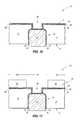
- an electrically insulative liner 16is formed within opening 14 , and then conductive materials 18 and 20 are formed within the lined opening.
- the electrically insulative linermay comprise any suitable composition or combination of compositions; and in some embodiments may comprise a doped glass; such as, for example, one or more of borophosphosilicate glass (BPSG), phosphosilicate glass (PSG), fluorosilicate glass (FSG), etc.
- BPSGborophosphosilicate glass
- PSGphosphosilicate glass
- FSGfluorosilicate glass
- the liner 16may be formed to any suitable thickness, and in some embodiments may be formed to a thickness within a range of from about 1000 angstroms to about 3000 angstroms; such as, for example, a thickness of about 1700 angstroms.
- the electrically conductive materials 18 and 20may comprise any suitable compositions or combinations of compositions.
- the electrically conductive material 20may comprise, consist essentially of, or consist of copper; and the material 18 may be a copper barrier material.
- the copper barrier materialmay include one or more of cobalt, ruthenium, tantalum, tantalum nitride, tungsten nitride and titanium nitride.
- the electrically conductive materials 18 and 20together form a first part 22 of an electrically conductive interconnect.
- the conductive material 20may be referred to as a core of the first part of the electrically conductive interconnect, and the material 18 may be referred to as a sheath that extends around such core.
- core 20may refer to core 20 as a copper-containing core, and to the material 18 as a copper barrier sheath around such core.
- the inventionalso includes embodiments in which other electrically conductive materials may be utilized in addition to, or alternatively to, the copper-containing cores and copper barrier sheaths.
- the copper barrier sheathsmay be omitted.
- the core 20is illustrated to project slightly outside of the opening 14 in the illustrated embodiment, and thus to extend outwardly beyond the side 9 of the semiconductor substrate.
- the coremay be formed to be flush with the side 9 of the substrate, or recessed relative to the side 9 of the substrate.
- the substrate 12may be thinned so that a distance, D, from the second side 11 of the substrate to the first part 22 of the electrically conductive interconnect is less than or equal to about 20 micrometers. In some embodiments, the thinning of the substrate may be omitted.
- patterned masking material 24is provided over the second side 11 of substrate 12 .
- An opening 26extends through the patterned masking material, with such opening being directly over the first part 22 of the interconnect.
- the masking material 24may comprise any suitable composition or combination of compositions; and in some embodiments may correspond to photolithographically-patterned photoresist.
- the opening 26is extended into the substrate 12 , and specifically is extended to the electrically insulative material 16 . Subsequently, the masking material 24 ( FIG. 5 ) is removed.
- the opening 26may be extended into substrate 12 with any suitable etch, or combination of etches; and in some embodiments may be extended into the substrate utilizing a deep reactive ion etch (DRIE) process.
- DRIEdeep reactive ion etch
- the opening 26 of FIG. 6may be referred to as a second opening, to distinguish it from the first opening 14 formed at the processing stage of FIG. 2 .
- the opening 26may be formed into or through the insulative material 16 in some embodiments.
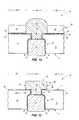
- electrically insulative material 28is formed along the second side 11 of the substrate 12 , and within the opening 26 .
- the electrically insulative material 28may comprise any suitable composition or combination of compositions; and in some embodiments may comprise, consist essentially of or consist of silicon dioxide or silicon nitride.
- the electrically insulative materialmay be formed with any suitable processing, including, for example, one or both of atomic layer deposition (ALD) and chemical vapor deposition (CVD).
- ALDatomic layer deposition
- CVDchemical vapor deposition
- the deposition processmay be a low-temperature process, and specifically may utilize a temperature of less than or equal to about 200° C. Such low-temperature processing may be desired in order to avoid thermally-induced damage to integrated circuit components associated with substrate 12 .
- the electrically insulative material 28is formed to be thicker along the surface 11 of substrate 12 than along the bottom of opening 26 . Such may occur if the opening 26 has a suitable aspect ratio such that the deposition along the bottom of opening 26 is slower than the deposition along the surface 11 ; and in some embodiments the opening 26 may have an aspect ratio of greater than or equal to 2:1. In some embodiments, the thickness of material 28 over surface 11 is at least about 5000 angstroms, and the thickness of material 28 along the bottom of opening 26 is less than or equal to about 3000 angstroms.
- the electrically insulative material 28is subjected to an anisotropic etch which punches through the bottom of material 28 , and also punches through liner 16 to expose the electrically conductive first part 22 of the interconnect.
- the electrical insulative materialremains along sidewalls of opening 26 , and across the surface 11 after the etch punches through the material 28 at the bottom of the opening 26 .
- etchingis conducted to extend the opening 26 through the sheath 18 and to the core 20 of the first part of the electrical interconnect.
- the opening 26may be extended to the sheath 18 rather than through the sheath 18 .
- FIG. 9shows a top view of the construction of FIG. 8 , and shows the opening 26 relative to the first part 22 of the interconnect.
- the interconnect part 22is shown in dashed-line to indicate that such is beneath other materials.
- electrically conductive materialsare formed across the second side 11 of substrate 12 , and within opening 26 .
- Such electrically conductive materialsmay comprise a copper barrier material 30 and a copper seed material 32 .
- the copper barrier materialmay comprise any of the materials discussed above as being suitable for utilization in copper barrier material 18 , and may be formed with any suitable processing; including, for example, one or more of ALD, CVD and physical vapor deposition (PVD).
- the copper seed materialmay comprise any suitable seed material, and may be formed with any suitable processing; such as, for example, one or more of ALD, CVD and PVD.
- a patterned mask 34is formed over the second side 11 of substrate 12 .
- the patterned maskcomprises a masking material 36 .
- the masking material 36may be any suitable composition or combination of compositions; and in some embodiments may comprise photolithographically-patterned photoresist.
- the patterned mask 34covers a first region 38 of the second side of the substrate, while leaving a second region 40 uncovered.
- the opening 26is within such uncovered second region.
- electrically conductive material 42is formed over the second side 11 of the substrate, and within the uncovered second region 40 of such second side.
- the material 42may comprise, consist essentially of, or consist of copper; and may be electrolytically-grown from the copper seed material 32 .
- the electrolytically-grown material 42merges with the seed material within the uncovered region 40 , so that the seed material within the uncovered region 40 effectively disappears as it becomes incorporated into the material 42 .
- the electrically conductive material 42may be formed to any suitable thickness. In the shown embodiment, the material 42 is formed to a thickness exceeding the height of mask 34 , but in other embodiments the material 42 may be formed to a thickness which does not exceed the height of the mask 34 .
- material 42may refer to material 42 as a copper-containing material, to the material 32 as a copper-containing seed material, and to the material 30 as a copper barrier material.
- the inventionalso includes embodiments in which other electrically conductive materials may be utilized in addition to, or alternatively to, the copper-containing materials and copper barrier materials.
- the copper barrier materialsmay be omitted.
- material 42is subjected to chemical-mechanical polishing (CMP) to form a planarized upper surface 43 extending across material 42 , and the mask 34 ( FIG. 12 ) is removed. Also, the copper barrier material 30 and seed material 32 ( FIG. 12 ) are removed from the region 38 of substrate 12 that had been covered by mask 34 .
- CMPchemical-mechanical polishing
- the electrically conductive materials 30 and 42are incorporated into a second part 44 of an electrical interconnect, with such second part of the electrical interconnect extending within the opening 26 .
- the first and second parts 22 and 44 of the electrical interconnectare electrically coupled with one another, and together form a through-substrate interconnect 100 .
- the second part 44 of the electrical interconnectincludes a pedestal 46 which is over the second side 11 of the substrate, and which has sidewalls 47 .
- the second part 44may be considered to comprise a core corresponding to material 42 , and to comprise a sheath corresponding to the material 30 around the core.
- material 42may be referred to as a core material of the second part 44 of the interconnect
- material 30may be referred to as a sheath material of the second part of the interconnect.
- the core 42may be a copper-containing core
- the sheath 30may be a copper barrier sheath.
- an electrically insulative structure 48is formed across the first region 38 of the substrate 12 , and along the sidewalls 47 of the pedestal 46 .
- the structure 48comprises electrically insulative material 50 .
- electrically insulative materialmay comprise any suitable composition or combination of compositions; and in some embodiments may comprise, consist essentially of, or consist of polyimide.
- FIG. 14shows a bonding material 52 formed over the electrically conductive core material 42 .
- such bonding materialmay comprise a solder-wettable material, and may be suitable for fabricating a bond to circuitry (not shown) external of the construction 10 .
- the bonding materialis shown provided directly over core material 42 , in some embodiments there may be one or more other layers between the bonding material and the core material.
- Such other layersmay comprise, for example, nickel, gold, or any other materials suitable for adhering the solder-wettable material to the core material; and in some embodiments may include materials known in the art as under bump materials.
- FIG. 8shows opening 26 extended to core 20 .
- the opening 26may be extended to the sheath 18 , rather than entirely through the sheath to the core 20 .
- FIGS. 15 and 16illustrate an example of such other embodiments.
- FIG. 15such shows a construction 10 a at a processing stage analogous to that of FIG. 8 ; but in which the opening 26 is extended to the electrically conductive sheath 18 of the first part 22 of the electrically conductive interconnect, and not to the core 20 of such first part of the electrically conductive interconnect.
- FIG. 16shows construction 10 a at a processing stage analogous to that of FIG. 14 (specifically, after processing analogous to that described above with reference to FIGS. 10-14 ), and shows a second part 44 of the through-substrate interconnect 100 having an electrically conductive sheath 30 which joins to the electrically conductive sheath 18 of the first part 22 of the through-substrate interconnect.
- FIGS. 1-16form the second part of the electrical interconnect within a single opening.
- the second part of the electrical interconnectmay be formed within multiple openings.
- An example embodiment method for forming the second part of the electrical interconnect within multiple openingsis described with reference to FIGS. 17-22 .
- a construction 10 bis shown at a processing stage analogous to that of FIG. 5 .
- the construction 10 blike the construction 10 of FIG. 5 , comprises the patterned masking material 24 formed across the second side 11 of substrate 12 .
- the construction 10 b of FIG. 17has three openings 60 - 62 patterned through the masking material 24 .
- the openings 60 - 62are all directly over the first part 22 of the electrical interconnect.
- the embodiment of FIG. 17is an example embodiment in which there are a plurality of openings patterned through the masking material.
- the plurality of openingsmay correspond to a different number of openings than the illustrated three openings.
- not all of the openingsare directly over the first part of the electrical interconnect. Instead, some of the openings may be in locations where anchor pins are desired.
- construction 10 bis subjected to processing analogous to that described above with reference to FIG. 6 to extend the openings 60 - 62 through substrate 12 , and to the electrically insulative material 16 .
- construction 10 bis shown at a processing stage analogous to that of FIG. 8 . Specifically, the construction is shown after formation of the electrically insulative material 28 across the side 11 of the substrate and within the openings 60 - 62 ; and after etching to extend the openings 60 - 62 through materials 16 and 18 and to the core 20 of the first part of the interconnect.
- FIG. 20shows a top view of the construction of FIG. 19 , and shows the openings 60 - 62 relative to the first part 22 of the interconnect.
- the first part 22is shown in dashed-line to indicate that such is beneath other materials. Additional openings 63 - 66 are visible in the top view of FIG. 19 , besides the openings 60 - 62 . All of the openings 60 - 66 are directly over the first part 22 of the interconnect; and accordingly all of such openings may be considered to be second openings which extend to the first part of the interconnect.
- the shown embodimenthas seven openings formed over the first part 22 of the interconnect, in other embodiments there may be less than seven openings formed over the first part of the interconnect, or more than seven openings formed over such first part.
- insulative material 28be formed under conditions such that the insulative material is thicker over the outer surface of substrate 12 than at the bottoms of the openings extending into such substrate.
- Such conditionsmay utilize openings having suitably high aspect ratios so that deposition of material 28 at the bottoms of the openings is slower than the deposition of material 28 across the outer surface of substrate 12 .
- a potential difficulty with the utilization of a single opening having a suitably high aspect ratio to achieve the desired deposition characteristics of material 28is that the portion of the conductive interconnect ultimately formed within such opening may be too narrow to achieve desired conductance characteristics.
- 19 and 20may enable suitably high aspect ratios to be achieved within the individual openings to enable the insulative material 28 to be formed thinner over bottoms of the openings than over the outer surface of substrate 12 , and yet may enable enough conductive material to be formed within the combined multiple openings so that the resulting interconnect has desired conductance characteristics.
- the multiple openings formed at the processing stage of FIGS. 19 and 20may have approximately the same dimensions as one another (as shown). In other embodiments, one or more of the openings may have substantially different dimensions than one or more others of the openings.
- construction 10 bis shown at a processing stage analogous to that of FIG. 14 .
- the constructioncomprises a through-substrate interconnect 100 having a first part 22 comprising core 20 and sheath 18 , and having a second part 44 comprising core 42 and sheath 30 .
- the second part 44comprises multiple conductive fingers 70 - 72 within the openings 60 - 62 , respectively. All of the conductive FIGS. 70-72 extend to the core 20 of the first part 22 of the through-substrate interconnect.
- core 20 and core 42may both comprise the same metal-containing composition as one another; and may, for example, both consist of copper.
- the cores 20 and 42may be considered to be metal-containing cores comprising a first composition; and the sheath 30 may be considered to comprise a second composition, different from the first composition (for instance, the sheath 30 may comprise a copper barrier material), and directly between the metal-containing cores 20 and 42 .
- FIG. 21shows the conductive fingers 70 - 72 extending to core 20 .
- the conductive fingers 70 - 72may extend to the sheath 18 , rather than entirely through such sheath to the core 20 (analogously to a construction discussed above with reference to FIGS. 15 and 16 ).
- FIG. 22illustrates a construction 10 c showing an example embodiment in which the conductive fingers 70 - 72 of the second part of the through-substrate interconnect 100 extend to the sheath 18 of the first part of the through-substrate interconnect.
- the sheaths 18 and 30may comprise the same composition as one another, and thus may merge to form a single layer between the conductive cores 42 and 20 . In other embodiments, the sheaths 18 and 30 may comprise different compositions from one another.
- FIGS. 23-25illustrate a method for patterning the second part of the through-substrate interconnect which may be utilized alternatively to the above-described patterning of FIGS. 10-14 .
- a construction 10 dis shown at a processing stage subsequent to that of FIG. 8 .
- the constructionis shown to comprise the first and second regions 38 and 40 discussed above with reference to FIG. 11 .
- An electrically insulative structure 80is patterned to be over the first region 38 of the substrate 12 of construction 10 d , and not over the second region 40 .
- the electrically insulative structurecomprises an electrically insulative material 82 which may comprise any suitable composition or combination of compositions; and in some embodiments may comprise, consist essentially of, or consist of polyimide.
- the electrically insulative materialmay be patterned into the configuration of structure 80 with any suitable processing. For instance, a photolithographically-patterned photoresist mask (not shown) may be formed over an expanse of material 82 , a pattern may be transferred from the mask into the expanse of material 82 with one or more suitable etches, and then the mask may be removed to leave the illustrated patterned structure 80 of material 82 .
- Copper barrier material 30 and copper seed material 32are formed over the insulative structure 80 , and across the region 40 which is not covered by structure 80 .
- copper-containing material 42is formed across material 30 .
- the copper-containing materialmay be electrolytically grown from the seed material 32 ( FIG. 23 ).
- the seed materialmerges with the electrolytically-grown copper, and thus is not shown at the processing stage of FIG. 24 .
- CMP and/or other suitable processingis utilized to remove the copper-containing material 42 and copper barrier material 30 from over the insulative material 82 , while leaving the copper-containing material 42 over the second region 40 of the substrate.
- solder-wetting materialanalogous to the material 52 of FIG. 14 may be provided over the copper-containing material 42 .
- FIG. 25has the second part 44 of the through-substrate interconnect 100 extending through the sheath 18 of the first part 22 of such interconnect.
- similar processing to that of FIGS. 23-25may be utilized to form constructions analogous to that of FIG. 16 in which the second part 44 of the electrical interconnect does not extend through the sheath 18 of the first part 22 of such electrical interconnect.
- FIG. 26shows a construction 10 e formed with processing similar to that of FIGS. 23-25 , and comprising a through-substrate interconnect 100 with multiple conductive fingers 70 - 72 .
- portion 44 of the through-substrate interconnects described hereinis referred to as a “second portion,” and the portion 22 is referred to as an “first portion,” in some embodiments the respective portions may be formed in an opposite order to that shown in the various figures provided herein. Thus, in some embodiments a multi-finger portion may be formed prior to another portion of a through-substrate interconnect.
- embodimentsdescribe formation of a single interconnect comprising first and second portions, the embodiments may also be considered as forming twin interconnects that couple to one another at an interface located partway through a substrate.
- each of the individual interconnects shown in the figuresmay be representative of a large plurality of interconnects simultaneously fabricated within a substrate.
- Such plurality of interconnectsmay have any suitable arrangement across a substrate, and may, for example, have arrangements analogous to those described in U.S. Pat. No. 6,943,106, which lists Kirby as the inventor, and Micron Technology, Inc. as the assignee.
- FIGS. 1-26form through-substrate electrical interconnects.
- anchor pinsmay be formed alongside the through-substrate interconnects during fabrication of the through-substrate interconnects. An example embodiment method for forming anchor pins is described with reference to FIGS. 27-31 .
- a construction 10 fis shown at a processing stage analogous to that of FIG. 17 .
- the construction 10 flike the construction 10 of FIG. 17 , comprises the patterned masking material 24 formed across the second side 11 of substrate 12 .
- the construction 10 f of FIG. 27has a pair of openings 110 and 112 patterned through the masking material 24 on opposing sides of the three openings 60 - 62 .
- the openings 110 and 112are laterally offset from the first part 22 of the electrical interconnect, and thus are not directly over such first part of the electrical interconnect.
- 27is an example embodiment in which there is at least one opening patterned through the masking material in a location which is not directly over the first part of an electrical interconnect.
- the number of openings that are not directly over such first partmay correspond to a different number of openings than the illustrated pair of openings.
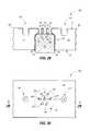
- construction 10 fis subjected to processing analogous to that described above with reference to FIG. 18 , and such processing extends the openings 110 and 112 into substrate 12 .
- construction 10 fis shown at a processing stage analogous to that of FIG. 19 .
- the constructionis shown after formation of the electrically insulative material 28 across the side 11 of the substrate and within the openings 60 - 62 , 110 and 112 ; and after etching to extend the openings 60 - 62 through materials 16 and 18 and to the core 20 of the first part of the interconnect.
- Such etchingmay or may not also recess the openings 110 and 112 into the substrate 12 to a depth below bottom surfaces of insulative material 11 within such openings.
- FIG. 30shows a top view of the construction of FIG. 29 , and shows the openings 60 - 62 , 110 and 112 relative to the first part 22 of the interconnect.
- the first part 22is shown in dashed-line to indicate that such is beneath other materials.
- Additional openings 63 - 66are visible in the top view of FIG. 29 , besides the openings 60 - 62 , 110 and 112 . All of the openings 60 - 66 are directly over the first part 22 of the interconnect, whereas the openings 110 and 112 are not directly over such first part of the interconnect.
- the multiple openings formed at the processing stage of FIGS. 29 and 30may have any suitable dimensions.
- construction 10 fis shown at a processing stage analogous to that of FIG. 21 .
- the constructioncomprises a through-substrate interconnect 100 having a first part 22 comprising core 20 and sheath 18 , and having a second part 44 comprising core 42 and sheath 30 .
- the second part 44comprises multiple conductive fingers 70 - 72 within the openings 60 - 62 , respectively. All of the conductive FIGS. 70-72 extend to the core 20 of the first part 22 of the through-substrate interconnect.
- the constructionalso comprises conductive material 42 extending into openings 110 and 112 to form anchor pins 114 and 116 extending into substrate 12 .
- Such anchor pinsmay assist in retaining the pad of material 42 to the substrate.
- the number and spacing of the anchor pinsmay be chosen to achieve desired retention of the pad of material 42 to the substrate, while avoiding undesired weakening of the substrate.
- Anchor pins analogous to those of FIG. 31may be utilized in combination with any of the embodiments described herein.
- FIG. 31shows the pad of material 42 oriented somewhat symmetrically relative to the first part 22 of the electrical interconnect (and specifically shows the pad material 42 extending about the same distance to both the right and the left of the first part of the interconnect along the cross-section section of FIG. 31 ), in other embodiments the pad material may be oriented asymmetrically relative to such first part of the electrical interconnect.
- FIG. 32shows a construction 10 g in which the pad of material 42 is provided to be laterally offset relative to the first part 22 of the electrical interconnect. In the shown embodiment, the material 42 forms an anchor pin 116 extending into the opening 112 .
- Some embodimentsinclude methods of forming interconnects through semiconductor substrates.
- a first openingmay be formed to extend from one side of a semiconductor substrate, and partway through the substrate.
- a first part of an electrically conductive interconnectmay be formed within the first opening.
- At least one second openingmay be formed to extend from a second side of the substrate to the first part of the electrically conductive interconnect.
- a second part of the electrically conductive interconnectmay be formed within the at least one second opening.
- Some embodimentsinclude methods of forming interconnects through semiconductor substrates.
- a first openingmay be formed to extend from one side of a semiconductor substrate, and partway through the substrate.
- a first part of an electrically conductive interconnectmay be formed within the first opening.
- At least one second openingmay be formed to extend from a second side of the substrate and directly over the first part of the electrically conductive interconnect.
- Electrically insulative materialmay be formed along the second side of the substrate and within the at least one second opening.
- the electrically insulative materialmay be removed from along a bottom of the at least one second opening while leaving the electrically insulative material along the second side of the substrate and along sidewalls of the at least one second opening After the electrically insulative material is removed from along the bottom of the at least one second opening, a region of the first part of the interconnect is exposed through the at least one second opening. A second part of the electrically conductive interconnect may then be formed within the at least one second opening.
- Some embodimentsinclude semiconductor constructions having an electrically conductive first part of a through-substrate interconnect, with said first part extending from a first side of a semiconductor substrate and partially through the substrate.
- the semiconductor constructionsmay also have an electrically conductive second part of the through-substrate interconnect, with the second part extending from a second side of the substrate in opposing relation to the first side, and comprising multiple separate electrically conductive fingers that all extend to the electrically conductive first part.
- Some embodimentsinclude semiconductor constructions containing a first electrically conductive part of a through-substrate interconnect, with said first part extending from a first side of a semiconductor substrate and partially through the substrate, and having a first metal-containing core.
- the semiconductor constructionsmay also contain a second electrically conductive part of the through-substrate interconnect, with the second part extending from a second side of the semiconductor substrate in opposing relation to the first side, with the second part having an electrically conductive sheath around a metal-containing core, and with the electrically conductive sheath of the second part being between the conductive core of the first part and the conductive core of the second part.
Landscapes
- Engineering & Computer Science (AREA)
- Computer Hardware Design (AREA)
- Microelectronics & Electronic Packaging (AREA)
- Power Engineering (AREA)
- Physics & Mathematics (AREA)
- Condensed Matter Physics & Semiconductors (AREA)
- General Physics & Mathematics (AREA)
- Manufacturing & Machinery (AREA)
- Geometry (AREA)
- Internal Circuitry In Semiconductor Integrated Circuit Devices (AREA)
Abstract
Description
Claims (26)
Priority Applications (9)
| Application Number | Priority Date | Filing Date | Title |
|---|---|---|---|
| US13/154,132US8853072B2 (en) | 2011-06-06 | 2011-06-06 | Methods of forming through-substrate interconnects |
| KR1020137034540AKR101538262B1 (en) | 2011-06-06 | 2012-05-03 | Semiconductor constructions having through-substrate interconnects, and methods of forming through-substrate interconnects |
| CN201280027691.3ACN103582933B (en) | 2011-06-06 | 2012-05-03 | Semiconductor construction with through-substrate interconnect and method of forming through-substrate interconnect |
| PCT/US2012/036401WO2012170129A2 (en) | 2011-06-06 | 2012-05-03 | Semiconductor constructions having through-substrate interconnects, and methods of forming through-substrate interconnects |
| EP12797279.2AEP2718964B1 (en) | 2011-06-06 | 2012-05-03 | Method of forming through-substrate interconnects |
| JP2014514461AJP5989104B2 (en) | 2011-06-06 | 2012-05-03 | Semiconductor structure having through-substrate interconnects and method for forming through-substrate interconnects |
| TW101118066ATWI497660B (en) | 2011-06-06 | 2012-05-21 | Semiconductor constructions having through-substrate interconnects, and methods of forming through-substrate interconnects |
| US14/505,925US9583419B2 (en) | 2011-06-06 | 2014-10-03 | Semiconductor constructions having through-substrate interconnects |
| US15/407,205US10121738B2 (en) | 2011-06-06 | 2017-01-16 | Semiconductor constructions |
Applications Claiming Priority (1)
| Application Number | Priority Date | Filing Date | Title |
|---|---|---|---|
| US13/154,132US8853072B2 (en) | 2011-06-06 | 2011-06-06 | Methods of forming through-substrate interconnects |
Related Child Applications (1)
| Application Number | Title | Priority Date | Filing Date |
|---|---|---|---|
| US14/505,925DivisionUS9583419B2 (en) | 2011-06-06 | 2014-10-03 | Semiconductor constructions having through-substrate interconnects |
Publications (2)
| Publication Number | Publication Date |
|---|---|
| US20120306084A1 US20120306084A1 (en) | 2012-12-06 |
| US8853072B2true US8853072B2 (en) | 2014-10-07 |
Family
ID=47261054
Family Applications (3)
| Application Number | Title | Priority Date | Filing Date |
|---|---|---|---|
| US13/154,132Active2031-12-01US8853072B2 (en) | 2011-06-06 | 2011-06-06 | Methods of forming through-substrate interconnects |
| US14/505,925ActiveUS9583419B2 (en) | 2011-06-06 | 2014-10-03 | Semiconductor constructions having through-substrate interconnects |
| US15/407,205Active2031-08-25US10121738B2 (en) | 2011-06-06 | 2017-01-16 | Semiconductor constructions |
Family Applications After (2)
| Application Number | Title | Priority Date | Filing Date |
|---|---|---|---|
| US14/505,925ActiveUS9583419B2 (en) | 2011-06-06 | 2014-10-03 | Semiconductor constructions having through-substrate interconnects |
| US15/407,205Active2031-08-25US10121738B2 (en) | 2011-06-06 | 2017-01-16 | Semiconductor constructions |
Country Status (7)
| Country | Link |
|---|---|
| US (3) | US8853072B2 (en) |
| EP (1) | EP2718964B1 (en) |
| JP (1) | JP5989104B2 (en) |
| KR (1) | KR101538262B1 (en) |
| CN (1) | CN103582933B (en) |
| TW (1) | TWI497660B (en) |
| WO (1) | WO2012170129A2 (en) |
Cited By (4)
| Publication number | Priority date | Publication date | Assignee | Title |
|---|---|---|---|---|
| US10559530B2 (en) | 2017-12-27 | 2020-02-11 | International Business Machines Corporation | Forming dual metallization interconnect structures in single metallization level |
| US20220059515A1 (en)* | 2016-11-28 | 2022-02-24 | Taiwan Semiconductor Manufacturing Co., Ltd. | Method of forming package structure |
| US20230025859A1 (en)* | 2021-07-13 | 2023-01-26 | Changxin Memory Technologies, Inc. | Semiconductor structure and method for forming same |
| US11791286B2 (en) | 2016-09-12 | 2023-10-17 | Samsung Electronics Co., Ltd. | Semiconductor device and semiconductor package |
Families Citing this family (14)
| Publication number | Priority date | Publication date | Assignee | Title |
|---|---|---|---|---|
| US8853072B2 (en) | 2011-06-06 | 2014-10-07 | Micron Technology, Inc. | Methods of forming through-substrate interconnects |
| US8609540B2 (en)* | 2011-06-20 | 2013-12-17 | Tessera, Inc. | Reliable packaging and interconnect structures |
| JP5814959B2 (en)* | 2013-02-21 | 2015-11-17 | 株式会社東芝 | Semiconductor device and manufacturing method thereof |
| US9252110B2 (en) | 2014-01-17 | 2016-02-02 | Taiwan Semiconductor Manufacturing Company, Ltd. | Interconnect structure and method of forming same |
| KR102253552B1 (en)* | 2014-03-28 | 2021-05-18 | 인텔 코포레이션 | Anchored interconnect |
| JP6363868B2 (en)* | 2014-05-12 | 2018-07-25 | 国立大学法人東北大学 | Semiconductor device and manufacturing method thereof |
| JP5994825B2 (en) | 2014-08-06 | 2016-09-21 | 大日本印刷株式会社 | Through electrode substrate, manufacturing method thereof, and semiconductor device using the through electrode substrate |
| CN104355284B (en)* | 2014-10-13 | 2016-06-29 | 华东光电集成器件研究所 | A kind of MEMS is two-sided to logical dielectric isolation structure and preparation method |
| JP6380486B2 (en)* | 2016-08-24 | 2018-08-29 | 大日本印刷株式会社 | Through electrode substrate, manufacturing method thereof, and semiconductor device using the through electrode substrate |
| US9997452B1 (en) | 2017-01-27 | 2018-06-12 | Micron Technology, Inc. | Forming conductive plugs for memory device |
| US10651087B2 (en)* | 2017-08-31 | 2020-05-12 | Yangtze Memory Technologies Co., Ltd. | Method for forming three-dimensional integrated wiring structure and semiconductor structure thereof |
| US10607887B2 (en) | 2017-08-31 | 2020-03-31 | Yangtze Memory Technologies Co., Ltd. | Method for forming three-dimensional integrated wiring structure and semiconductor structure thereof |
| US12119286B2 (en)* | 2021-05-19 | 2024-10-15 | Changxin Memory Technologies, Inc. | Die, memory and method of manufacturing die |
| US12255139B2 (en)* | 2021-09-01 | 2025-03-18 | Samsung Electronics Co., Ltd. | Semiconductor devices |
Citations (29)
| Publication number | Priority date | Publication date | Assignee | Title |
|---|---|---|---|---|
| US5496691A (en)* | 1994-02-08 | 1996-03-05 | Fuji Photo Film Co., Ltd. | Process for producing silver halide photographic material |
| US6114240A (en)* | 1997-12-18 | 2000-09-05 | Micron Technology, Inc. | Method for fabricating semiconductor components using focused laser beam |
| US6135679A (en) | 1998-05-12 | 2000-10-24 | Emuge-Werk Richard Glimpel Fabrikfuer Praezisionswerkzeuge Vormals Moschkau & Glimpel | Thread-cutting chuck using a minimum amount of lubrication |
| US20010011575A1 (en)* | 2000-01-27 | 2001-08-09 | Yasukazu Nakata | Process for producing an IC chip having a protective layer |
| US6284122B1 (en)* | 1998-06-09 | 2001-09-04 | International Lead Zinc Research Organization, Inc. | Production of a zinc-aluminum alloy coating by immersion into molten metal baths |
| US20030207558A1 (en)* | 2002-05-06 | 2003-11-06 | Taiwan Semiconductor Manufacturing Co., Ltd. | Method forming copper containing semiconductor features to prevent thermally induced defects |
| US20040018712A1 (en)* | 2002-07-29 | 2004-01-29 | Plas Hubert Vander | Method of forming a through-substrate interconnect |
| US6943106B1 (en) | 2004-02-20 | 2005-09-13 | Micron Technology, Inc. | Methods of fabricating interconnects for semiconductor components including plating solder-wetting material and solder filling |
| US20050221601A1 (en) | 2004-03-31 | 2005-10-06 | Nec Electronics Corporation | Semiconductor device and method for manufacturing the same |
| US7026721B2 (en)* | 1999-11-18 | 2006-04-11 | Taiwan Semiconductor Manufacturing Company, Ltd. | Method of improving copper pad adhesion |
| US7193327B2 (en)* | 2005-01-25 | 2007-03-20 | Taiwan Semiconductor Manufacturing Company, Ltd. | Barrier structure for semiconductor devices |
| US7198996B2 (en)* | 2000-12-27 | 2007-04-03 | Matsushita Electric Industrial Co., Ltd. | Component built-in module and method for producing the same |
| US7279419B2 (en)* | 2003-10-20 | 2007-10-09 | Micron Technology, Inc. | Formation of self-aligned contact plugs |
| US20070290300A1 (en)* | 2006-05-22 | 2007-12-20 | Sony Corporation | Semiconductor device and method for manufacturing same |
| US7626269B2 (en) | 2006-07-06 | 2009-12-01 | Micron Technology, Inc. | Semiconductor constructions and assemblies, and electronic systems |
| US7640660B2 (en)* | 2003-01-16 | 2010-01-05 | Fujitsu Limited | Method for manufacturing multilayer wiring board incorporating carbon fibers and glass fibers |
| US20100148371A1 (en)* | 2008-12-12 | 2010-06-17 | Qualcomm Incorporated | Via First Plus Via Last Technique for IC Interconnects |
| US20100224985A1 (en)* | 2009-03-05 | 2010-09-09 | Mihalis Michael | Chip-Scale Packaging with Protective Heat Spreader |
| US20100267199A1 (en)* | 2007-10-09 | 2010-10-21 | Keiichi Hatakeyama | Method for producing semiconductor chip with adhesive film, adhesive film for semiconductor used in the method, and method for producing semiconductor device |
| US20100264548A1 (en)* | 2009-04-16 | 2010-10-21 | Freescale Semiconductor, Inc. | Through substrate vias |
| US7855140B2 (en) | 2004-08-24 | 2010-12-21 | Micron Technology, Inc. | Method of forming vias in semiconductor substrates and resulting structures |
| US20110018114A1 (en) | 2009-07-22 | 2011-01-27 | Stats Chippac, Ltd. | Semiconductor Device and Method of Embedding Thermally Conductive Layer in Interconnect Structure for Heat Dissipation |
| US7884013B2 (en)* | 2005-01-31 | 2011-02-08 | Taiwan Semiconductor Manufacturing Co., Ltd. | Dual damascene with via liner |
| US20110147059A1 (en)* | 2009-12-17 | 2011-06-23 | Qing Ma | Substrate for integrated circuit devices including multi-layer glass core and methods of making the same |
| US20110207323A1 (en)* | 2010-02-25 | 2011-08-25 | Robert Ditizio | Method of forming and patterning conformal insulation layer in vias and etched structures |
| US20120083119A1 (en)* | 2008-05-12 | 2012-04-05 | Renesas Electronics Corporation | Semiconductor device and method of manufacturing the same |
| US20120187567A1 (en)* | 2008-06-10 | 2012-07-26 | Micron Technology, Inc. | Packaged microelectronic devices and methods for manufacturing packaged microelectronic devices |
| US8252680B2 (en)* | 2010-09-24 | 2012-08-28 | Intel Corporation | Methods and architectures for bottomless interconnect vias |
| WO2012170129A2 (en) | 2011-06-06 | 2012-12-13 | Micron Technology, Inc. | Semiconductor constructions having through-substrate interconnects, and methods of forming through-substrate interconnects |
Family Cites Families (28)
| Publication number | Priority date | Publication date | Assignee | Title |
|---|---|---|---|---|
| JPH06112327A (en)* | 1992-09-24 | 1994-04-22 | Sony Corp | Semiconductor device with multilayer interconnection structure and its manufacture |
| JPH09260492A (en)* | 1996-03-25 | 1997-10-03 | Toshiba Corp | Method for manufacturing semiconductor device |
| JP2004014657A (en)* | 2002-06-05 | 2004-01-15 | Toshiba Corp | Semiconductor chip, method of manufacturing the same, and three-dimensional stacked semiconductor device |
| JP4397583B2 (en)* | 2002-12-24 | 2010-01-13 | 株式会社フジクラ | Semiconductor device |
| JP4248928B2 (en)* | 2003-05-13 | 2009-04-02 | ローム株式会社 | Semiconductor chip manufacturing method, semiconductor device manufacturing method, semiconductor chip, and semiconductor device |
| JP4634045B2 (en)* | 2003-07-31 | 2011-02-16 | 富士通株式会社 | Semiconductor device manufacturing method, through electrode forming method, semiconductor device, composite semiconductor device, and mounting structure |
| JP2005196820A (en) | 2003-12-26 | 2005-07-21 | Toshiba Corp | Disk device, disk playback method, and disk |
| JP4327644B2 (en)* | 2004-03-31 | 2009-09-09 | Necエレクトロニクス株式会社 | Manufacturing method of semiconductor device |
| JP4544902B2 (en)* | 2004-04-26 | 2010-09-15 | 三洋電機株式会社 | Semiconductor device and manufacturing method thereof |
| JP2006196820A (en)* | 2005-01-17 | 2006-07-27 | Matsushita Electric Ind Co Ltd | Semiconductor device and manufacturing method thereof |
| JP2007081304A (en)* | 2005-09-16 | 2007-03-29 | Nippon Telegr & Teleph Corp <Ntt> | Semiconductor device and manufacturing method thereof |
| JP2007081301A (en) | 2005-09-16 | 2007-03-29 | Renesas Technology Corp | Semiconductor device manufacturing method and semiconductor device |
| JP4720432B2 (en) | 2005-10-28 | 2011-07-13 | 日本ビクター株式会社 | Slot structure and electronic equipment |
| JP4851163B2 (en)* | 2005-10-31 | 2012-01-11 | オンセミコンダクター・トレーディング・リミテッド | Manufacturing method of semiconductor device |
| US7524765B2 (en)* | 2005-11-02 | 2009-04-28 | Intel Corporation | Direct tailoring of the composition and density of ALD films |
| JP2008035020A (en) | 2006-07-27 | 2008-02-14 | Sky Kk | Response validity/invalidity circumstance notification system |
| JP2008060243A (en)* | 2006-08-30 | 2008-03-13 | Nec Electronics Corp | Semiconductor device and manufacturing method thereof |
| US7531445B2 (en)* | 2006-09-26 | 2009-05-12 | Hymite A/S | Formation of through-wafer electrical interconnections and other structures using a thin dielectric membrane |
| JP5117698B2 (en)* | 2006-09-27 | 2013-01-16 | ルネサスエレクトロニクス株式会社 | Semiconductor device |
| JP4415984B2 (en)* | 2006-12-06 | 2010-02-17 | ソニー株式会社 | Manufacturing method of semiconductor device |
| JP2010092895A (en)* | 2008-10-03 | 2010-04-22 | Sanyo Electric Co Ltd | Semiconductor device and method of manufacturing the same |
| US7939449B2 (en)* | 2008-06-03 | 2011-05-10 | Micron Technology, Inc. | Methods of forming hybrid conductive vias including small dimension active surface ends and larger dimension back side ends |
| JP5308145B2 (en)* | 2008-12-19 | 2013-10-09 | ルネサスエレクトロニクス株式会社 | Semiconductor device |
| JP5412506B2 (en)* | 2009-03-27 | 2014-02-12 | パナソニック株式会社 | Semiconductor device |
| JP2010232400A (en)* | 2009-03-27 | 2010-10-14 | Panasonic Corp | Semiconductor substrate, semiconductor substrate manufacturing method, and semiconductor package |
| US8791549B2 (en)* | 2009-09-22 | 2014-07-29 | Taiwan Semiconductor Manufacturing Company, Ltd. | Wafer backside interconnect structure connected to TSVs |
| JP5060535B2 (en) | 2009-09-24 | 2012-10-31 | 株式会社東芝 | Image processing device |
| WO2012036401A2 (en) | 2010-09-14 | 2012-03-22 | Kang Ungsuk | Method and system for recommending an internet domain |
- 2011
- 2011-06-06USUS13/154,132patent/US8853072B2/enactiveActive
- 2012
- 2012-05-03WOPCT/US2012/036401patent/WO2012170129A2/enactiveApplication Filing
- 2012-05-03KRKR1020137034540Apatent/KR101538262B1/enactiveActive
- 2012-05-03EPEP12797279.2Apatent/EP2718964B1/enactiveActive
- 2012-05-03JPJP2014514461Apatent/JP5989104B2/enactiveActive
- 2012-05-03CNCN201280027691.3Apatent/CN103582933B/enactiveActive
- 2012-05-21TWTW101118066Apatent/TWI497660B/enactive
- 2014
- 2014-10-03USUS14/505,925patent/US9583419B2/enactiveActive
- 2017
- 2017-01-16USUS15/407,205patent/US10121738B2/enactiveActive
Patent Citations (30)
| Publication number | Priority date | Publication date | Assignee | Title |
|---|---|---|---|---|
| US5496691A (en)* | 1994-02-08 | 1996-03-05 | Fuji Photo Film Co., Ltd. | Process for producing silver halide photographic material |
| US6114240A (en)* | 1997-12-18 | 2000-09-05 | Micron Technology, Inc. | Method for fabricating semiconductor components using focused laser beam |
| US6135679A (en) | 1998-05-12 | 2000-10-24 | Emuge-Werk Richard Glimpel Fabrikfuer Praezisionswerkzeuge Vormals Moschkau & Glimpel | Thread-cutting chuck using a minimum amount of lubrication |
| US6284122B1 (en)* | 1998-06-09 | 2001-09-04 | International Lead Zinc Research Organization, Inc. | Production of a zinc-aluminum alloy coating by immersion into molten metal baths |
| US7026721B2 (en)* | 1999-11-18 | 2006-04-11 | Taiwan Semiconductor Manufacturing Company, Ltd. | Method of improving copper pad adhesion |
| US20010011575A1 (en)* | 2000-01-27 | 2001-08-09 | Yasukazu Nakata | Process for producing an IC chip having a protective layer |
| US7198996B2 (en)* | 2000-12-27 | 2007-04-03 | Matsushita Electric Industrial Co., Ltd. | Component built-in module and method for producing the same |
| US20030207558A1 (en)* | 2002-05-06 | 2003-11-06 | Taiwan Semiconductor Manufacturing Co., Ltd. | Method forming copper containing semiconductor features to prevent thermally induced defects |
| US20040018712A1 (en)* | 2002-07-29 | 2004-01-29 | Plas Hubert Vander | Method of forming a through-substrate interconnect |
| US7640660B2 (en)* | 2003-01-16 | 2010-01-05 | Fujitsu Limited | Method for manufacturing multilayer wiring board incorporating carbon fibers and glass fibers |
| US7279419B2 (en)* | 2003-10-20 | 2007-10-09 | Micron Technology, Inc. | Formation of self-aligned contact plugs |
| US7410898B2 (en)* | 2004-02-20 | 2008-08-12 | Micron Technology, Inc. | Methods of fabricating interconnects for semiconductor components |
| US6943106B1 (en) | 2004-02-20 | 2005-09-13 | Micron Technology, Inc. | Methods of fabricating interconnects for semiconductor components including plating solder-wetting material and solder filling |
| US20050221601A1 (en) | 2004-03-31 | 2005-10-06 | Nec Electronics Corporation | Semiconductor device and method for manufacturing the same |
| US7855140B2 (en) | 2004-08-24 | 2010-12-21 | Micron Technology, Inc. | Method of forming vias in semiconductor substrates and resulting structures |
| US7193327B2 (en)* | 2005-01-25 | 2007-03-20 | Taiwan Semiconductor Manufacturing Company, Ltd. | Barrier structure for semiconductor devices |
| US7884013B2 (en)* | 2005-01-31 | 2011-02-08 | Taiwan Semiconductor Manufacturing Co., Ltd. | Dual damascene with via liner |
| US20070290300A1 (en)* | 2006-05-22 | 2007-12-20 | Sony Corporation | Semiconductor device and method for manufacturing same |
| US7626269B2 (en) | 2006-07-06 | 2009-12-01 | Micron Technology, Inc. | Semiconductor constructions and assemblies, and electronic systems |
| US20100267199A1 (en)* | 2007-10-09 | 2010-10-21 | Keiichi Hatakeyama | Method for producing semiconductor chip with adhesive film, adhesive film for semiconductor used in the method, and method for producing semiconductor device |
| US20120083119A1 (en)* | 2008-05-12 | 2012-04-05 | Renesas Electronics Corporation | Semiconductor device and method of manufacturing the same |
| US20120187567A1 (en)* | 2008-06-10 | 2012-07-26 | Micron Technology, Inc. | Packaged microelectronic devices and methods for manufacturing packaged microelectronic devices |
| US20100148371A1 (en)* | 2008-12-12 | 2010-06-17 | Qualcomm Incorporated | Via First Plus Via Last Technique for IC Interconnects |
| US20100224985A1 (en)* | 2009-03-05 | 2010-09-09 | Mihalis Michael | Chip-Scale Packaging with Protective Heat Spreader |
| US20100264548A1 (en)* | 2009-04-16 | 2010-10-21 | Freescale Semiconductor, Inc. | Through substrate vias |
| US20110018114A1 (en) | 2009-07-22 | 2011-01-27 | Stats Chippac, Ltd. | Semiconductor Device and Method of Embedding Thermally Conductive Layer in Interconnect Structure for Heat Dissipation |
| US20110147059A1 (en)* | 2009-12-17 | 2011-06-23 | Qing Ma | Substrate for integrated circuit devices including multi-layer glass core and methods of making the same |
| US20110207323A1 (en)* | 2010-02-25 | 2011-08-25 | Robert Ditizio | Method of forming and patterning conformal insulation layer in vias and etched structures |
| US8252680B2 (en)* | 2010-09-24 | 2012-08-28 | Intel Corporation | Methods and architectures for bottomless interconnect vias |
| WO2012170129A2 (en) | 2011-06-06 | 2012-12-13 | Micron Technology, Inc. | Semiconductor constructions having through-substrate interconnects, and methods of forming through-substrate interconnects |
Non-Patent Citations (2)
| Title |
|---|
| Abstract: Liu et al., "Failure mechanisms and optimum design for electroplated copper Through-Silicon Vias (TSV)", Electronic Components and Technology, May 26-29, 2009, pp. 624-629. |
| Yole Developpement, "3-D IC Commercialization Continues Despite Downturn", Semiconductor International. Retrieved Apr. 7, 2011 from http://www.semiconductor.net/article/453107-3-D-IC-Commercialization-Continues-Despite-Downturn-. |
Cited By (9)
| Publication number | Priority date | Publication date | Assignee | Title |
|---|---|---|---|---|
| US11791286B2 (en) | 2016-09-12 | 2023-10-17 | Samsung Electronics Co., Ltd. | Semiconductor device and semiconductor package |
| US20220059515A1 (en)* | 2016-11-28 | 2022-02-24 | Taiwan Semiconductor Manufacturing Co., Ltd. | Method of forming package structure |
| US11817437B2 (en)* | 2016-11-28 | 2023-11-14 | Taiwan Semiconductor Manufacturing Co., Ltd. | Method of forming package structure |
| US12191287B2 (en) | 2016-11-28 | 2025-01-07 | Taiwan Semiconductor Manufacturing Co., Ltd. | Package structure |
| US10559530B2 (en) | 2017-12-27 | 2020-02-11 | International Business Machines Corporation | Forming dual metallization interconnect structures in single metallization level |
| US11031337B2 (en) | 2017-12-27 | 2021-06-08 | International Business Machines Corporation | Forming dual metallization interconnect structures in single metallization level |
| US11037875B2 (en) | 2017-12-27 | 2021-06-15 | International Business Machines Corporation | Forming dual metallization interconnect structures in single metallization level |
| US20230025859A1 (en)* | 2021-07-13 | 2023-01-26 | Changxin Memory Technologies, Inc. | Semiconductor structure and method for forming same |
| US12125749B2 (en)* | 2021-07-13 | 2024-10-22 | Changxin Memory Technologies, Inc. | Semiconductor structure and method for forming same |
Also Published As
| Publication number | Publication date |
|---|---|
| EP2718964A4 (en) | 2014-11-26 |
| EP2718964A2 (en) | 2014-04-16 |
| WO2012170129A2 (en) | 2012-12-13 |
| CN103582933B (en) | 2017-02-15 |
| EP2718964B1 (en) | 2017-08-23 |
| TWI497660B (en) | 2015-08-21 |
| CN103582933A (en) | 2014-02-12 |
| KR101538262B1 (en) | 2015-07-20 |
| KR20140026572A (en) | 2014-03-05 |
| US20120306084A1 (en) | 2012-12-06 |
| JP2014517534A (en) | 2014-07-17 |
| US20150130029A1 (en) | 2015-05-14 |
| TW201301459A (en) | 2013-01-01 |
| US10121738B2 (en) | 2018-11-06 |
| US9583419B2 (en) | 2017-02-28 |
| US20170125342A1 (en) | 2017-05-04 |
| WO2012170129A3 (en) | 2013-03-14 |
| JP5989104B2 (en) | 2016-09-07 |
Similar Documents
| Publication | Publication Date | Title |
|---|---|---|
| US10121738B2 (en) | Semiconductor constructions | |
| US8836085B2 (en) | Cost-effective TSV formation | |
| US7936052B2 (en) | On-chip RF shields with backside redistribution lines | |
| US20220208749A1 (en) | Semiconductor devices and methods of manufacture thereof | |
| US7786584B2 (en) | Through substrate via semiconductor components | |
| US9390973B2 (en) | On-chip RF shields with backside redistribution lines | |
| KR101137624B1 (en) | via structure and via etching process of forming the same | |
| TWI553824B (en) | Stacked integrated circuits with redistribution lines and forming method thereof | |
| US9613847B2 (en) | Integration of shallow trench isolation and through-substrate vias into integrated circuit designs | |
| TWI524492B (en) | 3-d integration using multi stage vias | |
| CN102237300B (en) | Through-substrate via structure and manufacturing method thereof | |
| US20100072579A1 (en) | Through Substrate Conductors | |
| KR20100037015A (en) | Methods of forming electrical interconnects using electroless plating techniques that inhibit void formation | |
| US9029257B2 (en) | Semiconductor constructions and methods of planarizing across a plurality of electrically conductive posts | |
| US20130313710A1 (en) | Semiconductor Constructions and Methods of Forming Semiconductor Constructions | |
| TWI888880B (en) | Semiconductor device and method for forming same |
Legal Events
| Date | Code | Title | Description |
|---|---|---|---|
| AS | Assignment | Owner name:MICRON TECHNOLOGY, INC, IDAHO Free format text:ASSIGNMENT OF ASSIGNORS INTEREST;ASSIGNORS:WOOD, ALAN G.;IRELAND, PHILIP J.;SIGNING DATES FROM 20110513 TO 20110602;REEL/FRAME:026396/0511 | |
| FEPP | Fee payment procedure | Free format text:PAYOR NUMBER ASSIGNED (ORIGINAL EVENT CODE: ASPN); ENTITY STATUS OF PATENT OWNER: LARGE ENTITY | |
| STCF | Information on status: patent grant | Free format text:PATENTED CASE | |
| CC | Certificate of correction | ||
| AS | Assignment | Owner name:U.S. BANK NATIONAL ASSOCIATION, AS COLLATERAL AGENT, CALIFORNIA Free format text:SECURITY INTEREST;ASSIGNOR:MICRON TECHNOLOGY, INC.;REEL/FRAME:038669/0001 Effective date:20160426 Owner name:U.S. BANK NATIONAL ASSOCIATION, AS COLLATERAL AGEN Free format text:SECURITY INTEREST;ASSIGNOR:MICRON TECHNOLOGY, INC.;REEL/FRAME:038669/0001 Effective date:20160426 | |
| AS | Assignment | Owner name:MORGAN STANLEY SENIOR FUNDING, INC., AS COLLATERAL AGENT, MARYLAND Free format text:PATENT SECURITY AGREEMENT;ASSIGNOR:MICRON TECHNOLOGY, INC.;REEL/FRAME:038954/0001 Effective date:20160426 Owner name:MORGAN STANLEY SENIOR FUNDING, INC., AS COLLATERAL Free format text:PATENT SECURITY AGREEMENT;ASSIGNOR:MICRON TECHNOLOGY, INC.;REEL/FRAME:038954/0001 Effective date:20160426 | |
| AS | Assignment | Owner name:U.S. BANK NATIONAL ASSOCIATION, AS COLLATERAL AGENT, CALIFORNIA Free format text:CORRECTIVE ASSIGNMENT TO CORRECT THE REPLACE ERRONEOUSLY FILED PATENT #7358718 WITH THE CORRECT PATENT #7358178 PREVIOUSLY RECORDED ON REEL 038669 FRAME 0001. ASSIGNOR(S) HEREBY CONFIRMS THE SECURITY INTEREST;ASSIGNOR:MICRON TECHNOLOGY, INC.;REEL/FRAME:043079/0001 Effective date:20160426 Owner name:U.S. BANK NATIONAL ASSOCIATION, AS COLLATERAL AGEN Free format text:CORRECTIVE ASSIGNMENT TO CORRECT THE REPLACE ERRONEOUSLY FILED PATENT #7358718 WITH THE CORRECT PATENT #7358178 PREVIOUSLY RECORDED ON REEL 038669 FRAME 0001. ASSIGNOR(S) HEREBY CONFIRMS THE SECURITY INTEREST;ASSIGNOR:MICRON TECHNOLOGY, INC.;REEL/FRAME:043079/0001 Effective date:20160426 | |
| MAFP | Maintenance fee payment | Free format text:PAYMENT OF MAINTENANCE FEE, 4TH YEAR, LARGE ENTITY (ORIGINAL EVENT CODE: M1551) Year of fee payment:4 | |
| AS | Assignment | Owner name:JPMORGAN CHASE BANK, N.A., AS COLLATERAL AGENT, ILLINOIS Free format text:SECURITY INTEREST;ASSIGNORS:MICRON TECHNOLOGY, INC.;MICRON SEMICONDUCTOR PRODUCTS, INC.;REEL/FRAME:047540/0001 Effective date:20180703 Owner name:JPMORGAN CHASE BANK, N.A., AS COLLATERAL AGENT, IL Free format text:SECURITY INTEREST;ASSIGNORS:MICRON TECHNOLOGY, INC.;MICRON SEMICONDUCTOR PRODUCTS, INC.;REEL/FRAME:047540/0001 Effective date:20180703 | |
| AS | Assignment | Owner name:MICRON TECHNOLOGY, INC., IDAHO Free format text:RELEASE BY SECURED PARTY;ASSIGNOR:U.S. BANK NATIONAL ASSOCIATION, AS COLLATERAL AGENT;REEL/FRAME:047243/0001 Effective date:20180629 | |
| AS | Assignment | Owner name:MICRON TECHNOLOGY, INC., IDAHO Free format text:RELEASE BY SECURED PARTY;ASSIGNOR:MORGAN STANLEY SENIOR FUNDING, INC., AS COLLATERAL AGENT;REEL/FRAME:050937/0001 Effective date:20190731 | |
| AS | Assignment | Owner name:MICRON TECHNOLOGY, INC., IDAHO Free format text:RELEASE BY SECURED PARTY;ASSIGNOR:JPMORGAN CHASE BANK, N.A., AS COLLATERAL AGENT;REEL/FRAME:051028/0001 Effective date:20190731 Owner name:MICRON SEMICONDUCTOR PRODUCTS, INC., IDAHO Free format text:RELEASE BY SECURED PARTY;ASSIGNOR:JPMORGAN CHASE BANK, N.A., AS COLLATERAL AGENT;REEL/FRAME:051028/0001 Effective date:20190731 | |
| MAFP | Maintenance fee payment | Free format text:PAYMENT OF MAINTENANCE FEE, 8TH YEAR, LARGE ENTITY (ORIGINAL EVENT CODE: M1552); ENTITY STATUS OF PATENT OWNER: LARGE ENTITY Year of fee payment:8 |