US8852278B2 - Lateral cage with integrated plate - Google Patents
Lateral cage with integrated plateDownload PDFInfo
- Publication number
- US8852278B2 US8852278B2US13/364,282US201213364282AUS8852278B2US 8852278 B2US8852278 B2US 8852278B2US 201213364282 AUS201213364282 AUS 201213364282AUS 8852278 B2US8852278 B2US 8852278B2
- Authority
- US
- United States
- Prior art keywords
- plate
- cage
- halves
- throughhole
- height
- Prior art date
- Legal status (The legal status is an assumption and is not a legal conclusion. Google has not performed a legal analysis and makes no representation as to the accuracy of the status listed.)
- Active, expires
Links
- 230000004927fusionEffects0.000claimsabstractdescription24
- 238000003780insertionMethods0.000claimsdescription11
- 230000037431insertionEffects0.000claimsdescription11
- 238000000034methodMethods0.000claimsdescription9
- 230000013011matingEffects0.000abstractdescription2
- 229920000049Carbon (fiber)Polymers0.000description14
- 239000004917carbon fiberSubstances0.000description14
- 239000000463materialSubstances0.000description14
- VNWKTOKETHGBQD-UHFFFAOYSA-NmethaneChemical classCVNWKTOKETHGBQD-UHFFFAOYSA-N0.000description12
- 239000002131composite materialSubstances0.000description11
- 239000004696Poly ether ether ketoneSubstances0.000description10
- 229920002530polyetherether ketonePolymers0.000description10
- 239000007943implantSubstances0.000description9
- 229910052751metalInorganic materials0.000description8
- 239000002184metalSubstances0.000description8
- 238000013459approachMethods0.000description6
- 239000000919ceramicSubstances0.000description6
- 229920000642polymerPolymers0.000description6
- 210000000988bone and boneAnatomy0.000description5
- 150000002576ketonesChemical class0.000description5
- 229910001069Ti alloyInorganic materials0.000description4
- 229910045601alloyInorganic materials0.000description4
- 239000000956alloySubstances0.000description4
- 238000004873anchoringMethods0.000description4
- 229920001652poly(etherketoneketone)Polymers0.000description4
- 229910001220stainless steelInorganic materials0.000description4
- 239000010935stainless steelSubstances0.000description4
- MCMNRKCIXSYSNV-UHFFFAOYSA-NZirconium dioxideChemical compoundO=[Zr]=OMCMNRKCIXSYSNV-UHFFFAOYSA-N0.000description3
- 238000010276constructionMethods0.000description3
- -1poly(vinyl fluoride)Polymers0.000description3
- 229920008285Poly(ether ketone) PEKPolymers0.000description2
- RTAQQCXQSZGOHL-UHFFFAOYSA-NTitaniumChemical compound[Ti]RTAQQCXQSZGOHL-UHFFFAOYSA-N0.000description2
- IUWCPXJTIPQGTE-UHFFFAOYSA-Nchromium cobaltChemical compound[Cr].[Co].[Co].[Co]IUWCPXJTIPQGTE-UHFFFAOYSA-N0.000description2
- 238000002513implantationMethods0.000description2
- 210000004705lumbosacral regionAnatomy0.000description2
- 239000007769metal materialSubstances0.000description2
- 150000002739metalsChemical class0.000description2
- 239000000203mixtureSubstances0.000description2
- 239000010936titaniumSubstances0.000description2
- VYZAMTAEIAYCRO-UHFFFAOYSA-NChromiumChemical compound[Cr]VYZAMTAEIAYCRO-UHFFFAOYSA-N0.000description1
- 229910000684Cobalt-chromeInorganic materials0.000description1
- 229910001200FerrotitaniumInorganic materials0.000description1
- AEMRFAOFKBGASW-UHFFFAOYSA-NGlycolic acidPolymersOCC(O)=OAEMRFAOFKBGASW-UHFFFAOYSA-N0.000description1
- FYYHWMGAXLPEAU-UHFFFAOYSA-NMagnesiumChemical compound[Mg]FYYHWMGAXLPEAU-UHFFFAOYSA-N0.000description1
- 229920001283Polyalkylene terephthalatePolymers0.000description1
- 239000004952PolyamideSubstances0.000description1
- 229920000954PolyglycolidePolymers0.000description1
- 229920000265PolyparaphenylenePolymers0.000description1
- 208000035965Postoperative ComplicationsDiseases0.000description1
- 102000007056Recombinant Fusion ProteinsHuman genes0.000description1
- 108010008281Recombinant Fusion ProteinsProteins0.000description1
- 229910000883Ti6Al4VInorganic materials0.000description1
- PNEYBMLMFCGWSK-UHFFFAOYSA-Naluminium oxideInorganic materials[O-2].[O-2].[O-2].[Al+3].[Al+3]PNEYBMLMFCGWSK-UHFFFAOYSA-N0.000description1
- 210000003484anatomyAnatomy0.000description1
- 208000037873arthrodesisDiseases0.000description1
- 125000003118aryl groupChemical group0.000description1
- 239000008280bloodSubstances0.000description1
- 210000004369bloodAnatomy0.000description1
- 210000001185bone marrowAnatomy0.000description1
- 239000001506calcium phosphateSubstances0.000description1
- 239000004918carbon fiber reinforced polymerSubstances0.000description1
- 238000005516engineering processMethods0.000description1
- 239000003102growth factorSubstances0.000description1
- 229910052588hydroxylapatiteInorganic materials0.000description1
- 208000015181infectious diseaseDiseases0.000description1
- 229910052749magnesiumInorganic materials0.000description1
- 239000011777magnesiumSubstances0.000description1
- 230000003472neutralizing effectEffects0.000description1
- 238000012856packingMethods0.000description1
- XYJRXVWERLGGKC-UHFFFAOYSA-Dpentacalcium;hydroxide;triphosphateChemical compound[OH-].[Ca+2].[Ca+2].[Ca+2].[Ca+2].[Ca+2].[O-]P([O-])([O-])=O.[O-]P([O-])([O-])=O.[O-]P([O-])([O-])=OXYJRXVWERLGGKC-UHFFFAOYSA-D0.000description1
- 229920000747poly(lactic acid)Polymers0.000description1
- 229920002647polyamidePolymers0.000description1
- 229920000728polyesterPolymers0.000description1
- 229920005594polymer fiberPolymers0.000description1
- 239000002861polymer materialSubstances0.000description1
- 229920000098polyolefinPolymers0.000description1
- 239000004810polytetrafluoroethyleneSubstances0.000description1
- 229920001343polytetrafluoroethylenePolymers0.000description1
- 229920002620polyvinyl fluoridePolymers0.000description1
- 210000002097psoas muscleAnatomy0.000description1
- 229910001256stainless steel alloyInorganic materials0.000description1
- 238000001356surgical procedureMethods0.000description1
- 210000001519tissueAnatomy0.000description1
- 230000000451tissue damageEffects0.000description1
- 231100000827tissue damageToxicity0.000description1
- 229910052719titaniumInorganic materials0.000description1
- QORWJWZARLRLPR-UHFFFAOYSA-Htricalcium bis(phosphate)Chemical compound[Ca+2].[Ca+2].[Ca+2].[O-]P([O-])([O-])=O.[O-]P([O-])([O-])=OQORWJWZARLRLPR-UHFFFAOYSA-H0.000description1
- 229940078499tricalcium phosphateDrugs0.000description1
- 229910000391tricalcium phosphateInorganic materials0.000description1
- 235000019731tricalcium phosphateNutrition0.000description1
- 230000003966vascular damageEffects0.000description1
Images


Classifications
- A—HUMAN NECESSITIES
- A61—MEDICAL OR VETERINARY SCIENCE; HYGIENE
- A61F—FILTERS IMPLANTABLE INTO BLOOD VESSELS; PROSTHESES; DEVICES PROVIDING PATENCY TO, OR PREVENTING COLLAPSING OF, TUBULAR STRUCTURES OF THE BODY, e.g. STENTS; ORTHOPAEDIC, NURSING OR CONTRACEPTIVE DEVICES; FOMENTATION; TREATMENT OR PROTECTION OF EYES OR EARS; BANDAGES, DRESSINGS OR ABSORBENT PADS; FIRST-AID KITS
- A61F2/00—Filters implantable into blood vessels; Prostheses, i.e. artificial substitutes or replacements for parts of the body; Appliances for connecting them with the body; Devices providing patency to, or preventing collapsing of, tubular structures of the body, e.g. stents
- A61F2/02—Prostheses implantable into the body
- A61F2/30—Joints
- A61F2/44—Joints for the spine, e.g. vertebrae, spinal discs
- A61F2/4455—Joints for the spine, e.g. vertebrae, spinal discs for the fusion of spinal bodies, e.g. intervertebral fusion of adjacent spinal bodies, e.g. fusion cages
- A61F2/447—Joints for the spine, e.g. vertebrae, spinal discs for the fusion of spinal bodies, e.g. intervertebral fusion of adjacent spinal bodies, e.g. fusion cages substantially parallelepipedal, e.g. having a rectangular or trapezoidal cross-section
- A—HUMAN NECESSITIES
- A61—MEDICAL OR VETERINARY SCIENCE; HYGIENE
- A61F—FILTERS IMPLANTABLE INTO BLOOD VESSELS; PROSTHESES; DEVICES PROVIDING PATENCY TO, OR PREVENTING COLLAPSING OF, TUBULAR STRUCTURES OF THE BODY, e.g. STENTS; ORTHOPAEDIC, NURSING OR CONTRACEPTIVE DEVICES; FOMENTATION; TREATMENT OR PROTECTION OF EYES OR EARS; BANDAGES, DRESSINGS OR ABSORBENT PADS; FIRST-AID KITS
- A61F2/00—Filters implantable into blood vessels; Prostheses, i.e. artificial substitutes or replacements for parts of the body; Appliances for connecting them with the body; Devices providing patency to, or preventing collapsing of, tubular structures of the body, e.g. stents
- A61F2/02—Prostheses implantable into the body
- A61F2/30—Joints
- A61F2/44—Joints for the spine, e.g. vertebrae, spinal discs
- A61F2/442—Intervertebral or spinal discs, e.g. resilient
- A—HUMAN NECESSITIES
- A61—MEDICAL OR VETERINARY SCIENCE; HYGIENE
- A61F—FILTERS IMPLANTABLE INTO BLOOD VESSELS; PROSTHESES; DEVICES PROVIDING PATENCY TO, OR PREVENTING COLLAPSING OF, TUBULAR STRUCTURES OF THE BODY, e.g. STENTS; ORTHOPAEDIC, NURSING OR CONTRACEPTIVE DEVICES; FOMENTATION; TREATMENT OR PROTECTION OF EYES OR EARS; BANDAGES, DRESSINGS OR ABSORBENT PADS; FIRST-AID KITS
- A61F2/00—Filters implantable into blood vessels; Prostheses, i.e. artificial substitutes or replacements for parts of the body; Appliances for connecting them with the body; Devices providing patency to, or preventing collapsing of, tubular structures of the body, e.g. stents
- A61F2/02—Prostheses implantable into the body
- A61F2/30—Joints
- A61F2/3094—Designing or manufacturing processes
- A61F2/30965—Reinforcing the prosthesis by embedding particles or fibres during moulding or dipping
- A—HUMAN NECESSITIES
- A61—MEDICAL OR VETERINARY SCIENCE; HYGIENE
- A61F—FILTERS IMPLANTABLE INTO BLOOD VESSELS; PROSTHESES; DEVICES PROVIDING PATENCY TO, OR PREVENTING COLLAPSING OF, TUBULAR STRUCTURES OF THE BODY, e.g. STENTS; ORTHOPAEDIC, NURSING OR CONTRACEPTIVE DEVICES; FOMENTATION; TREATMENT OR PROTECTION OF EYES OR EARS; BANDAGES, DRESSINGS OR ABSORBENT PADS; FIRST-AID KITS
- A61F2/00—Filters implantable into blood vessels; Prostheses, i.e. artificial substitutes or replacements for parts of the body; Appliances for connecting them with the body; Devices providing patency to, or preventing collapsing of, tubular structures of the body, e.g. stents
- A61F2/02—Prostheses implantable into the body
- A61F2/28—Bones
- A61F2002/2817—Bone stimulation by chemical reactions or by osteogenic or biological products for enhancing ossification, e.g. by bone morphogenetic or morphogenic proteins [BMP] or by transforming growth factors [TGF]
- A—HUMAN NECESSITIES
- A61—MEDICAL OR VETERINARY SCIENCE; HYGIENE
- A61F—FILTERS IMPLANTABLE INTO BLOOD VESSELS; PROSTHESES; DEVICES PROVIDING PATENCY TO, OR PREVENTING COLLAPSING OF, TUBULAR STRUCTURES OF THE BODY, e.g. STENTS; ORTHOPAEDIC, NURSING OR CONTRACEPTIVE DEVICES; FOMENTATION; TREATMENT OR PROTECTION OF EYES OR EARS; BANDAGES, DRESSINGS OR ABSORBENT PADS; FIRST-AID KITS
- A61F2/00—Filters implantable into blood vessels; Prostheses, i.e. artificial substitutes or replacements for parts of the body; Appliances for connecting them with the body; Devices providing patency to, or preventing collapsing of, tubular structures of the body, e.g. stents
- A61F2/02—Prostheses implantable into the body
- A61F2/28—Bones
- A61F2002/2835—Bone graft implants for filling a bony defect or an endoprosthesis cavity, e.g. by synthetic material or biological material
- A—HUMAN NECESSITIES
- A61—MEDICAL OR VETERINARY SCIENCE; HYGIENE
- A61F—FILTERS IMPLANTABLE INTO BLOOD VESSELS; PROSTHESES; DEVICES PROVIDING PATENCY TO, OR PREVENTING COLLAPSING OF, TUBULAR STRUCTURES OF THE BODY, e.g. STENTS; ORTHOPAEDIC, NURSING OR CONTRACEPTIVE DEVICES; FOMENTATION; TREATMENT OR PROTECTION OF EYES OR EARS; BANDAGES, DRESSINGS OR ABSORBENT PADS; FIRST-AID KITS
- A61F2/00—Filters implantable into blood vessels; Prostheses, i.e. artificial substitutes or replacements for parts of the body; Appliances for connecting them with the body; Devices providing patency to, or preventing collapsing of, tubular structures of the body, e.g. stents
- A61F2/02—Prostheses implantable into the body
- A61F2/30—Joints
- A61F2002/30001—Additional features of subject-matter classified in A61F2/28, A61F2/30 and subgroups thereof
- A61F2002/30316—The prosthesis having different structural features at different locations within the same prosthesis; Connections between prosthetic parts; Special structural features of bone or joint prostheses not otherwise provided for
- A61F2002/30329—Connections or couplings between prosthetic parts, e.g. between modular parts; Connecting elements
- A61F2002/30331—Connections or couplings between prosthetic parts, e.g. between modular parts; Connecting elements made by longitudinally pushing a protrusion into a complementarily-shaped recess, e.g. held by friction fit
- A61F2002/30362—Connections or couplings between prosthetic parts, e.g. between modular parts; Connecting elements made by longitudinally pushing a protrusion into a complementarily-shaped recess, e.g. held by friction fit with possibility of relative movement between the protrusion and the recess
- A61F2002/3037—Translation along the common longitudinal axis, e.g. piston
- A—HUMAN NECESSITIES
- A61—MEDICAL OR VETERINARY SCIENCE; HYGIENE
- A61F—FILTERS IMPLANTABLE INTO BLOOD VESSELS; PROSTHESES; DEVICES PROVIDING PATENCY TO, OR PREVENTING COLLAPSING OF, TUBULAR STRUCTURES OF THE BODY, e.g. STENTS; ORTHOPAEDIC, NURSING OR CONTRACEPTIVE DEVICES; FOMENTATION; TREATMENT OR PROTECTION OF EYES OR EARS; BANDAGES, DRESSINGS OR ABSORBENT PADS; FIRST-AID KITS
- A61F2/00—Filters implantable into blood vessels; Prostheses, i.e. artificial substitutes or replacements for parts of the body; Appliances for connecting them with the body; Devices providing patency to, or preventing collapsing of, tubular structures of the body, e.g. stents
- A61F2/02—Prostheses implantable into the body
- A61F2/30—Joints
- A61F2002/30001—Additional features of subject-matter classified in A61F2/28, A61F2/30 and subgroups thereof
- A61F2002/30316—The prosthesis having different structural features at different locations within the same prosthesis; Connections between prosthetic parts; Special structural features of bone or joint prostheses not otherwise provided for
- A61F2002/30329—Connections or couplings between prosthetic parts, e.g. between modular parts; Connecting elements
- A61F2002/30383—Connections or couplings between prosthetic parts, e.g. between modular parts; Connecting elements made by laterally inserting a protrusion, e.g. a rib into a complementarily-shaped groove
- A61F2002/3039—Connections or couplings between prosthetic parts, e.g. between modular parts; Connecting elements made by laterally inserting a protrusion, e.g. a rib into a complementarily-shaped groove with possibility of relative movement of the rib within the groove
- A61F2002/30392—Rotation
- A—HUMAN NECESSITIES
- A61—MEDICAL OR VETERINARY SCIENCE; HYGIENE
- A61F—FILTERS IMPLANTABLE INTO BLOOD VESSELS; PROSTHESES; DEVICES PROVIDING PATENCY TO, OR PREVENTING COLLAPSING OF, TUBULAR STRUCTURES OF THE BODY, e.g. STENTS; ORTHOPAEDIC, NURSING OR CONTRACEPTIVE DEVICES; FOMENTATION; TREATMENT OR PROTECTION OF EYES OR EARS; BANDAGES, DRESSINGS OR ABSORBENT PADS; FIRST-AID KITS
- A61F2/00—Filters implantable into blood vessels; Prostheses, i.e. artificial substitutes or replacements for parts of the body; Appliances for connecting them with the body; Devices providing patency to, or preventing collapsing of, tubular structures of the body, e.g. stents
- A61F2/02—Prostheses implantable into the body
- A61F2/30—Joints
- A61F2002/30001—Additional features of subject-matter classified in A61F2/28, A61F2/30 and subgroups thereof
- A61F2002/30316—The prosthesis having different structural features at different locations within the same prosthesis; Connections between prosthetic parts; Special structural features of bone or joint prostheses not otherwise provided for
- A61F2002/30329—Connections or couplings between prosthetic parts, e.g. between modular parts; Connecting elements
- A61F2002/30383—Connections or couplings between prosthetic parts, e.g. between modular parts; Connecting elements made by laterally inserting a protrusion, e.g. a rib into a complementarily-shaped groove
- A61F2002/3039—Connections or couplings between prosthetic parts, e.g. between modular parts; Connecting elements made by laterally inserting a protrusion, e.g. a rib into a complementarily-shaped groove with possibility of relative movement of the rib within the groove
- A61F2002/30397—Limited lateral translation of the rib within a larger groove
- A—HUMAN NECESSITIES
- A61—MEDICAL OR VETERINARY SCIENCE; HYGIENE
- A61F—FILTERS IMPLANTABLE INTO BLOOD VESSELS; PROSTHESES; DEVICES PROVIDING PATENCY TO, OR PREVENTING COLLAPSING OF, TUBULAR STRUCTURES OF THE BODY, e.g. STENTS; ORTHOPAEDIC, NURSING OR CONTRACEPTIVE DEVICES; FOMENTATION; TREATMENT OR PROTECTION OF EYES OR EARS; BANDAGES, DRESSINGS OR ABSORBENT PADS; FIRST-AID KITS
- A61F2/00—Filters implantable into blood vessels; Prostheses, i.e. artificial substitutes or replacements for parts of the body; Appliances for connecting them with the body; Devices providing patency to, or preventing collapsing of, tubular structures of the body, e.g. stents
- A61F2/02—Prostheses implantable into the body
- A61F2/30—Joints
- A61F2002/30001—Additional features of subject-matter classified in A61F2/28, A61F2/30 and subgroups thereof
- A61F2002/30316—The prosthesis having different structural features at different locations within the same prosthesis; Connections between prosthetic parts; Special structural features of bone or joint prostheses not otherwise provided for
- A61F2002/30329—Connections or couplings between prosthetic parts, e.g. between modular parts; Connecting elements
- A61F2002/30383—Connections or couplings between prosthetic parts, e.g. between modular parts; Connecting elements made by laterally inserting a protrusion, e.g. a rib into a complementarily-shaped groove
- A61F2002/3039—Connections or couplings between prosthetic parts, e.g. between modular parts; Connecting elements made by laterally inserting a protrusion, e.g. a rib into a complementarily-shaped groove with possibility of relative movement of the rib within the groove
- A61F2002/30398—Sliding
- A—HUMAN NECESSITIES
- A61—MEDICAL OR VETERINARY SCIENCE; HYGIENE
- A61F—FILTERS IMPLANTABLE INTO BLOOD VESSELS; PROSTHESES; DEVICES PROVIDING PATENCY TO, OR PREVENTING COLLAPSING OF, TUBULAR STRUCTURES OF THE BODY, e.g. STENTS; ORTHOPAEDIC, NURSING OR CONTRACEPTIVE DEVICES; FOMENTATION; TREATMENT OR PROTECTION OF EYES OR EARS; BANDAGES, DRESSINGS OR ABSORBENT PADS; FIRST-AID KITS
- A61F2/00—Filters implantable into blood vessels; Prostheses, i.e. artificial substitutes or replacements for parts of the body; Appliances for connecting them with the body; Devices providing patency to, or preventing collapsing of, tubular structures of the body, e.g. stents
- A61F2/02—Prostheses implantable into the body
- A61F2/30—Joints
- A61F2002/30001—Additional features of subject-matter classified in A61F2/28, A61F2/30 and subgroups thereof
- A61F2002/30316—The prosthesis having different structural features at different locations within the same prosthesis; Connections between prosthetic parts; Special structural features of bone or joint prostheses not otherwise provided for
- A61F2002/30329—Connections or couplings between prosthetic parts, e.g. between modular parts; Connecting elements
- A61F2002/30471—Connections or couplings between prosthetic parts, e.g. between modular parts; Connecting elements connected by a hinged linkage mechanism, e.g. of the single-bar or multi-bar linkage type
- A—HUMAN NECESSITIES
- A61—MEDICAL OR VETERINARY SCIENCE; HYGIENE
- A61F—FILTERS IMPLANTABLE INTO BLOOD VESSELS; PROSTHESES; DEVICES PROVIDING PATENCY TO, OR PREVENTING COLLAPSING OF, TUBULAR STRUCTURES OF THE BODY, e.g. STENTS; ORTHOPAEDIC, NURSING OR CONTRACEPTIVE DEVICES; FOMENTATION; TREATMENT OR PROTECTION OF EYES OR EARS; BANDAGES, DRESSINGS OR ABSORBENT PADS; FIRST-AID KITS
- A61F2/00—Filters implantable into blood vessels; Prostheses, i.e. artificial substitutes or replacements for parts of the body; Appliances for connecting them with the body; Devices providing patency to, or preventing collapsing of, tubular structures of the body, e.g. stents
- A61F2/02—Prostheses implantable into the body
- A61F2/30—Joints
- A61F2002/30001—Additional features of subject-matter classified in A61F2/28, A61F2/30 and subgroups thereof
- A61F2002/30316—The prosthesis having different structural features at different locations within the same prosthesis; Connections between prosthetic parts; Special structural features of bone or joint prostheses not otherwise provided for
- A61F2002/30329—Connections or couplings between prosthetic parts, e.g. between modular parts; Connecting elements
- A61F2002/30476—Connections or couplings between prosthetic parts, e.g. between modular parts; Connecting elements locked by an additional locking mechanism
- A61F2002/30492—Connections or couplings between prosthetic parts, e.g. between modular parts; Connecting elements locked by an additional locking mechanism using a locking pin
- A—HUMAN NECESSITIES
- A61—MEDICAL OR VETERINARY SCIENCE; HYGIENE
- A61F—FILTERS IMPLANTABLE INTO BLOOD VESSELS; PROSTHESES; DEVICES PROVIDING PATENCY TO, OR PREVENTING COLLAPSING OF, TUBULAR STRUCTURES OF THE BODY, e.g. STENTS; ORTHOPAEDIC, NURSING OR CONTRACEPTIVE DEVICES; FOMENTATION; TREATMENT OR PROTECTION OF EYES OR EARS; BANDAGES, DRESSINGS OR ABSORBENT PADS; FIRST-AID KITS
- A61F2/00—Filters implantable into blood vessels; Prostheses, i.e. artificial substitutes or replacements for parts of the body; Appliances for connecting them with the body; Devices providing patency to, or preventing collapsing of, tubular structures of the body, e.g. stents
- A61F2/02—Prostheses implantable into the body
- A61F2/30—Joints
- A61F2002/30001—Additional features of subject-matter classified in A61F2/28, A61F2/30 and subgroups thereof
- A61F2002/30316—The prosthesis having different structural features at different locations within the same prosthesis; Connections between prosthetic parts; Special structural features of bone or joint prostheses not otherwise provided for
- A61F2002/30329—Connections or couplings between prosthetic parts, e.g. between modular parts; Connecting elements
- A61F2002/30476—Connections or couplings between prosthetic parts, e.g. between modular parts; Connecting elements locked by an additional locking mechanism
- A61F2002/30517—Connections or couplings between prosthetic parts, e.g. between modular parts; Connecting elements locked by an additional locking mechanism using a locking plate
- A—HUMAN NECESSITIES
- A61—MEDICAL OR VETERINARY SCIENCE; HYGIENE
- A61F—FILTERS IMPLANTABLE INTO BLOOD VESSELS; PROSTHESES; DEVICES PROVIDING PATENCY TO, OR PREVENTING COLLAPSING OF, TUBULAR STRUCTURES OF THE BODY, e.g. STENTS; ORTHOPAEDIC, NURSING OR CONTRACEPTIVE DEVICES; FOMENTATION; TREATMENT OR PROTECTION OF EYES OR EARS; BANDAGES, DRESSINGS OR ABSORBENT PADS; FIRST-AID KITS
- A61F2/00—Filters implantable into blood vessels; Prostheses, i.e. artificial substitutes or replacements for parts of the body; Appliances for connecting them with the body; Devices providing patency to, or preventing collapsing of, tubular structures of the body, e.g. stents
- A61F2/02—Prostheses implantable into the body
- A61F2/30—Joints
- A61F2002/30001—Additional features of subject-matter classified in A61F2/28, A61F2/30 and subgroups thereof
- A61F2002/30316—The prosthesis having different structural features at different locations within the same prosthesis; Connections between prosthetic parts; Special structural features of bone or joint prostheses not otherwise provided for
- A61F2002/30535—Special structural features of bone or joint prostheses not otherwise provided for
- A61F2002/30576—Special structural features of bone or joint prostheses not otherwise provided for with extending fixation tabs
- A61F2002/30578—Special structural features of bone or joint prostheses not otherwise provided for with extending fixation tabs having apertures, e.g. for receiving fixation screws
- A—HUMAN NECESSITIES
- A61—MEDICAL OR VETERINARY SCIENCE; HYGIENE
- A61F—FILTERS IMPLANTABLE INTO BLOOD VESSELS; PROSTHESES; DEVICES PROVIDING PATENCY TO, OR PREVENTING COLLAPSING OF, TUBULAR STRUCTURES OF THE BODY, e.g. STENTS; ORTHOPAEDIC, NURSING OR CONTRACEPTIVE DEVICES; FOMENTATION; TREATMENT OR PROTECTION OF EYES OR EARS; BANDAGES, DRESSINGS OR ABSORBENT PADS; FIRST-AID KITS
- A61F2/00—Filters implantable into blood vessels; Prostheses, i.e. artificial substitutes or replacements for parts of the body; Appliances for connecting them with the body; Devices providing patency to, or preventing collapsing of, tubular structures of the body, e.g. stents
- A61F2/02—Prostheses implantable into the body
- A61F2/30—Joints
- A61F2002/30001—Additional features of subject-matter classified in A61F2/28, A61F2/30 and subgroups thereof
- A61F2002/30316—The prosthesis having different structural features at different locations within the same prosthesis; Connections between prosthetic parts; Special structural features of bone or joint prostheses not otherwise provided for
- A61F2002/30535—Special structural features of bone or joint prostheses not otherwise provided for
- A61F2002/30593—Special structural features of bone or joint prostheses not otherwise provided for hollow
- A—HUMAN NECESSITIES
- A61—MEDICAL OR VETERINARY SCIENCE; HYGIENE
- A61F—FILTERS IMPLANTABLE INTO BLOOD VESSELS; PROSTHESES; DEVICES PROVIDING PATENCY TO, OR PREVENTING COLLAPSING OF, TUBULAR STRUCTURES OF THE BODY, e.g. STENTS; ORTHOPAEDIC, NURSING OR CONTRACEPTIVE DEVICES; FOMENTATION; TREATMENT OR PROTECTION OF EYES OR EARS; BANDAGES, DRESSINGS OR ABSORBENT PADS; FIRST-AID KITS
- A61F2/00—Filters implantable into blood vessels; Prostheses, i.e. artificial substitutes or replacements for parts of the body; Appliances for connecting them with the body; Devices providing patency to, or preventing collapsing of, tubular structures of the body, e.g. stents
- A61F2/02—Prostheses implantable into the body
- A61F2/30—Joints
- A61F2002/30001—Additional features of subject-matter classified in A61F2/28, A61F2/30 and subgroups thereof
- A61F2002/30621—Features concerning the anatomical functioning or articulation of the prosthetic joint
- A61F2002/30624—Hinged joint, e.g. with transverse axle restricting the movement
- A—HUMAN NECESSITIES
- A61—MEDICAL OR VETERINARY SCIENCE; HYGIENE
- A61F—FILTERS IMPLANTABLE INTO BLOOD VESSELS; PROSTHESES; DEVICES PROVIDING PATENCY TO, OR PREVENTING COLLAPSING OF, TUBULAR STRUCTURES OF THE BODY, e.g. STENTS; ORTHOPAEDIC, NURSING OR CONTRACEPTIVE DEVICES; FOMENTATION; TREATMENT OR PROTECTION OF EYES OR EARS; BANDAGES, DRESSINGS OR ABSORBENT PADS; FIRST-AID KITS
- A61F2/00—Filters implantable into blood vessels; Prostheses, i.e. artificial substitutes or replacements for parts of the body; Appliances for connecting them with the body; Devices providing patency to, or preventing collapsing of, tubular structures of the body, e.g. stents
- A61F2/02—Prostheses implantable into the body
- A61F2/30—Joints
- A61F2/30767—Special external or bone-contacting surface, e.g. coating for improving bone ingrowth
- A61F2/30771—Special external or bone-contacting surface, e.g. coating for improving bone ingrowth applied in original prostheses, e.g. holes or grooves
- A61F2002/30772—Apertures or holes, e.g. of circular cross section
- A61F2002/30777—Oblong apertures
- A—HUMAN NECESSITIES
- A61—MEDICAL OR VETERINARY SCIENCE; HYGIENE
- A61F—FILTERS IMPLANTABLE INTO BLOOD VESSELS; PROSTHESES; DEVICES PROVIDING PATENCY TO, OR PREVENTING COLLAPSING OF, TUBULAR STRUCTURES OF THE BODY, e.g. STENTS; ORTHOPAEDIC, NURSING OR CONTRACEPTIVE DEVICES; FOMENTATION; TREATMENT OR PROTECTION OF EYES OR EARS; BANDAGES, DRESSINGS OR ABSORBENT PADS; FIRST-AID KITS
- A61F2/00—Filters implantable into blood vessels; Prostheses, i.e. artificial substitutes or replacements for parts of the body; Appliances for connecting them with the body; Devices providing patency to, or preventing collapsing of, tubular structures of the body, e.g. stents
- A61F2/02—Prostheses implantable into the body
- A61F2/30—Joints
- A61F2/30767—Special external or bone-contacting surface, e.g. coating for improving bone ingrowth
- A61F2/30771—Special external or bone-contacting surface, e.g. coating for improving bone ingrowth applied in original prostheses, e.g. holes or grooves
- A61F2002/30772—Apertures or holes, e.g. of circular cross section
- A61F2002/30784—Plurality of holes
- A61F2002/30785—Plurality of holes parallel
- A—HUMAN NECESSITIES
- A61—MEDICAL OR VETERINARY SCIENCE; HYGIENE
- A61F—FILTERS IMPLANTABLE INTO BLOOD VESSELS; PROSTHESES; DEVICES PROVIDING PATENCY TO, OR PREVENTING COLLAPSING OF, TUBULAR STRUCTURES OF THE BODY, e.g. STENTS; ORTHOPAEDIC, NURSING OR CONTRACEPTIVE DEVICES; FOMENTATION; TREATMENT OR PROTECTION OF EYES OR EARS; BANDAGES, DRESSINGS OR ABSORBENT PADS; FIRST-AID KITS
- A61F2/00—Filters implantable into blood vessels; Prostheses, i.e. artificial substitutes or replacements for parts of the body; Appliances for connecting them with the body; Devices providing patency to, or preventing collapsing of, tubular structures of the body, e.g. stents
- A61F2/02—Prostheses implantable into the body
- A61F2/30—Joints
- A61F2/30767—Special external or bone-contacting surface, e.g. coating for improving bone ingrowth
- A61F2/30771—Special external or bone-contacting surface, e.g. coating for improving bone ingrowth applied in original prostheses, e.g. holes or grooves
- A61F2002/30772—Apertures or holes, e.g. of circular cross section
- A61F2002/30784—Plurality of holes
- A61F2002/30789—Plurality of holes perpendicular with respect to each other
- A—HUMAN NECESSITIES
- A61—MEDICAL OR VETERINARY SCIENCE; HYGIENE
- A61F—FILTERS IMPLANTABLE INTO BLOOD VESSELS; PROSTHESES; DEVICES PROVIDING PATENCY TO, OR PREVENTING COLLAPSING OF, TUBULAR STRUCTURES OF THE BODY, e.g. STENTS; ORTHOPAEDIC, NURSING OR CONTRACEPTIVE DEVICES; FOMENTATION; TREATMENT OR PROTECTION OF EYES OR EARS; BANDAGES, DRESSINGS OR ABSORBENT PADS; FIRST-AID KITS
- A61F2/00—Filters implantable into blood vessels; Prostheses, i.e. artificial substitutes or replacements for parts of the body; Appliances for connecting them with the body; Devices providing patency to, or preventing collapsing of, tubular structures of the body, e.g. stents
- A61F2/02—Prostheses implantable into the body
- A61F2/30—Joints
- A61F2/30767—Special external or bone-contacting surface, e.g. coating for improving bone ingrowth
- A61F2/30771—Special external or bone-contacting surface, e.g. coating for improving bone ingrowth applied in original prostheses, e.g. holes or grooves
- A61F2002/30878—Special external or bone-contacting surface, e.g. coating for improving bone ingrowth applied in original prostheses, e.g. holes or grooves with non-sharp protrusions, for instance contacting the bone for anchoring, e.g. keels, pegs, pins, posts, shanks, stems, struts
- A61F2002/30891—Plurality of protrusions
- A—HUMAN NECESSITIES
- A61—MEDICAL OR VETERINARY SCIENCE; HYGIENE
- A61F—FILTERS IMPLANTABLE INTO BLOOD VESSELS; PROSTHESES; DEVICES PROVIDING PATENCY TO, OR PREVENTING COLLAPSING OF, TUBULAR STRUCTURES OF THE BODY, e.g. STENTS; ORTHOPAEDIC, NURSING OR CONTRACEPTIVE DEVICES; FOMENTATION; TREATMENT OR PROTECTION OF EYES OR EARS; BANDAGES, DRESSINGS OR ABSORBENT PADS; FIRST-AID KITS
- A61F2/00—Filters implantable into blood vessels; Prostheses, i.e. artificial substitutes or replacements for parts of the body; Appliances for connecting them with the body; Devices providing patency to, or preventing collapsing of, tubular structures of the body, e.g. stents
- A61F2/02—Prostheses implantable into the body
- A61F2/30—Joints
- A61F2/30767—Special external or bone-contacting surface, e.g. coating for improving bone ingrowth
- A61F2/30771—Special external or bone-contacting surface, e.g. coating for improving bone ingrowth applied in original prostheses, e.g. holes or grooves
- A61F2002/30904—Special external or bone-contacting surface, e.g. coating for improving bone ingrowth applied in original prostheses, e.g. holes or grooves serrated profile, i.e. saw-toothed
- A—HUMAN NECESSITIES
- A61—MEDICAL OR VETERINARY SCIENCE; HYGIENE
- A61F—FILTERS IMPLANTABLE INTO BLOOD VESSELS; PROSTHESES; DEVICES PROVIDING PATENCY TO, OR PREVENTING COLLAPSING OF, TUBULAR STRUCTURES OF THE BODY, e.g. STENTS; ORTHOPAEDIC, NURSING OR CONTRACEPTIVE DEVICES; FOMENTATION; TREATMENT OR PROTECTION OF EYES OR EARS; BANDAGES, DRESSINGS OR ABSORBENT PADS; FIRST-AID KITS
- A61F2/00—Filters implantable into blood vessels; Prostheses, i.e. artificial substitutes or replacements for parts of the body; Appliances for connecting them with the body; Devices providing patency to, or preventing collapsing of, tubular structures of the body, e.g. stents
- A61F2/02—Prostheses implantable into the body
- A61F2/30—Joints
- A61F2/30767—Special external or bone-contacting surface, e.g. coating for improving bone ingrowth
- A61F2002/3092—Special external or bone-contacting surface, e.g. coating for improving bone ingrowth having an open-celled or open-pored structure
- A—HUMAN NECESSITIES
- A61—MEDICAL OR VETERINARY SCIENCE; HYGIENE
- A61F—FILTERS IMPLANTABLE INTO BLOOD VESSELS; PROSTHESES; DEVICES PROVIDING PATENCY TO, OR PREVENTING COLLAPSING OF, TUBULAR STRUCTURES OF THE BODY, e.g. STENTS; ORTHOPAEDIC, NURSING OR CONTRACEPTIVE DEVICES; FOMENTATION; TREATMENT OR PROTECTION OF EYES OR EARS; BANDAGES, DRESSINGS OR ABSORBENT PADS; FIRST-AID KITS
- A61F2310/00—Prostheses classified in A61F2/28 or A61F2/30 - A61F2/44 being constructed from or coated with a particular material
- A61F2310/00005—The prosthesis being constructed from a particular material
- A61F2310/00011—Metals or alloys
- A61F2310/00017—Iron- or Fe-based alloys, e.g. stainless steel
- A—HUMAN NECESSITIES
- A61—MEDICAL OR VETERINARY SCIENCE; HYGIENE
- A61F—FILTERS IMPLANTABLE INTO BLOOD VESSELS; PROSTHESES; DEVICES PROVIDING PATENCY TO, OR PREVENTING COLLAPSING OF, TUBULAR STRUCTURES OF THE BODY, e.g. STENTS; ORTHOPAEDIC, NURSING OR CONTRACEPTIVE DEVICES; FOMENTATION; TREATMENT OR PROTECTION OF EYES OR EARS; BANDAGES, DRESSINGS OR ABSORBENT PADS; FIRST-AID KITS
- A61F2310/00—Prostheses classified in A61F2/28 or A61F2/30 - A61F2/44 being constructed from or coated with a particular material
- A61F2310/00005—The prosthesis being constructed from a particular material
- A61F2310/00011—Metals or alloys
- A61F2310/00023—Titanium or titanium-based alloys, e.g. Ti-Ni alloys
- A—HUMAN NECESSITIES
- A61—MEDICAL OR VETERINARY SCIENCE; HYGIENE
- A61F—FILTERS IMPLANTABLE INTO BLOOD VESSELS; PROSTHESES; DEVICES PROVIDING PATENCY TO, OR PREVENTING COLLAPSING OF, TUBULAR STRUCTURES OF THE BODY, e.g. STENTS; ORTHOPAEDIC, NURSING OR CONTRACEPTIVE DEVICES; FOMENTATION; TREATMENT OR PROTECTION OF EYES OR EARS; BANDAGES, DRESSINGS OR ABSORBENT PADS; FIRST-AID KITS
- A61F2310/00—Prostheses classified in A61F2/28 or A61F2/30 - A61F2/44 being constructed from or coated with a particular material
- A61F2310/00005—The prosthesis being constructed from a particular material
- A61F2310/00011—Metals or alloys
- A61F2310/00029—Cobalt-based alloys, e.g. Co-Cr alloys or Vitallium
- A—HUMAN NECESSITIES
- A61—MEDICAL OR VETERINARY SCIENCE; HYGIENE
- A61F—FILTERS IMPLANTABLE INTO BLOOD VESSELS; PROSTHESES; DEVICES PROVIDING PATENCY TO, OR PREVENTING COLLAPSING OF, TUBULAR STRUCTURES OF THE BODY, e.g. STENTS; ORTHOPAEDIC, NURSING OR CONTRACEPTIVE DEVICES; FOMENTATION; TREATMENT OR PROTECTION OF EYES OR EARS; BANDAGES, DRESSINGS OR ABSORBENT PADS; FIRST-AID KITS
- A61F2310/00—Prostheses classified in A61F2/28 or A61F2/30 - A61F2/44 being constructed from or coated with a particular material
- A61F2310/00005—The prosthesis being constructed from a particular material
- A61F2310/00179—Ceramics or ceramic-like structures
- A61F2310/00185—Ceramics or ceramic-like structures based on metal oxides
- A61F2310/00203—Ceramics or ceramic-like structures based on metal oxides containing alumina or aluminium oxide
- A—HUMAN NECESSITIES
- A61—MEDICAL OR VETERINARY SCIENCE; HYGIENE
- A61F—FILTERS IMPLANTABLE INTO BLOOD VESSELS; PROSTHESES; DEVICES PROVIDING PATENCY TO, OR PREVENTING COLLAPSING OF, TUBULAR STRUCTURES OF THE BODY, e.g. STENTS; ORTHOPAEDIC, NURSING OR CONTRACEPTIVE DEVICES; FOMENTATION; TREATMENT OR PROTECTION OF EYES OR EARS; BANDAGES, DRESSINGS OR ABSORBENT PADS; FIRST-AID KITS
- A61F2310/00—Prostheses classified in A61F2/28 or A61F2/30 - A61F2/44 being constructed from or coated with a particular material
- A61F2310/00005—The prosthesis being constructed from a particular material
- A61F2310/00179—Ceramics or ceramic-like structures
- A61F2310/00185—Ceramics or ceramic-like structures based on metal oxides
- A61F2310/00239—Ceramics or ceramic-like structures based on metal oxides containing zirconia or zirconium oxide ZrO2
Definitions
- a lateral access approachis frequently selected to deliver interbody fusion cages to the lumbar spine.
- the lateral approachis thought to minimize posterior and/or anterior tissue damage as well as reduce surgery time, associated blood loss, vascular damage and infection risk.
- U.S. Pat. No. 7,594,931discloses an intervertebral arthrodesis implant for insertion in an intervertebral space separating opposite faces of two adjacent vertebrae.
- the implanthas a ring-shaped intervertebral cage having a bar that extends perpendicular to the axis of the spine.
- the barhas a height less than the rest of the cage.
- a surface of the cage contacting the vertebraehas an undulating shape for limiting sliding of the cage in a plane parallel to the vertebral faces.
- WO2011-080535discloses anchoring devices, anchoring systems for intervertebral implants, intervertebral implants, and instruments and methods for implanting the implants.
- these various objectsshare the feature of comprising or cooperating with an anchoring device having a body comprising at least one curved plate elongated along a longitudinal axis.
- the plateis designed to be inserted through a passage crossing at least a part of the implant in order to penetrate into at least one vertebral endplate and attach this implant onto this vertebral endplate by means of at least one stop retaining the implant.
- the body of the anchoring devicecomprises at least one longitudinal rib on at least a part of at least one of its faces, the rib being designed to cooperate with a groove made in a passage of implant.
- the fusion cageis mounted with a plate that secures the cage to the adjacent vertebral bodies.
- US Published Patent Application 2010-0004747discloses a spinal fixation device comprising a trans-vertebral and intra-vertebral plate and a rectangular cage with a slot for the plate for neutralizing intervertebral movement in spinal interbody fusion.
- the rectangular cage with a vertical or oblique slotis inserted into the intervertebral space from the lateral or anterior side of the spinal column.
- the plateis then inserted through the slot of the cage and hammered into and buried inside the two adjacent vertebral bodies to achieve three-dimensional intervertebral fixation.
- the present inventorhas noted that, in the lateral cage-with-plate device disclosed by Lin, the orientation of the plate during insertion produces a relatively large profile, extending far above and below the height of the disc space, thereby detracting from the minimally invasive, tissue-sparing nature of the lateral approach.
- the present inventionseeks to provide a lateral cage-with-plate device that can be inserted in a minimally invasive manner, preferably through a portal such as a tube.
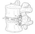
- the present inventionrelates to an intervertebral fusion cage having a plate pivotally attached thereto.
- the plate and cageare pivotally coupled but move independently of each other.
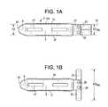
- the plateis made up of two smaller plate-halves: a superior plate half and an inferior plate half. Together, both plate halves form the larger plate.
- One or two cross pinsalso join the plate halves to the cage, thus allowing the plate halves to pivot about the cage.
- the platesare joined to each other using the cross pin.
- Each plate halfcan have one or more throughholes passing therethrough. Typically, a first throughhole is present at a first end of the plate half and may traverse the plate depth (i.e., it runs in the anterior-posterior direction). The above-mentioned cross pin passes through this first throughhole and thereby pivotally connects the plate half to the cage.
- a second throughholemay be present at a second end of the plate half and run transverse to the first throughhole. It runs in the frontal plane and may traverse the plate width. Through this second throughhole, the surgeon may pass a bone screw in order to secure the plate half to the adjacent vertebral body.
- the device of the present inventionhas two configurations: an open configuration and a closed configuration.
- the closed configurationthe plate halves-are adjacent each other and run in the medial-lateral axis of the cage.
- This configurationhas a small profile and so is amenable to insertion through a portal.
- the open configurationprojects the plate halves perpendicularly to the cage (spanning the height of the cage) and so can accept screws for fixation to adjacent vertebral bodies.
- the device of the present inventionwill encounter fewer difficulties when it is placed down a portal and its plate is manipulated into position. Mating the plate to the cage will reduce the chances of micromotion and improve fusion rates, resulting in improved patient outcomes. As compared to the Lin plate, the device of the present invention also reduces the stretching of the psoas muscle during implantation, resulting in reduced post-operative complications.
- rotational freedom of this devicewill allow for fixation with variable plate angles to adjust to the patient's anatomy.
- an intervertebral fusion devicecomprising:
- FIGS. 1 a - 1 kdiscloses various views of the device of the present invention
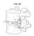
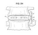
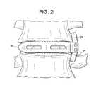
- FIGS. 2 a - 2 idisclose the device of the present invention at various stages of insertion into a disc space.
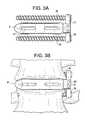
- FIGS. 3 a - 3 cdisclose the device of the present invention with screws.
- FIGS. 4 a - 4 cdisclose embodiments of the device having a single cross pin.
- an intervertebral fusion device 1comprising:
- the devicefurther comprises c) a cross pin 25 , wherein the cage further comprises a pair of flanges 27 extending from the same sidewall of the cage, each flange having a throughhole 29 , wherein the flange throughholes are aligned, wherein the first and second half of the plate each has a first end portion 31 having a throughhole 33 , wherein the throughholes of each plate half are aligned, and wherein the pin passes through the througholes of the flanges and the throughholes of the plate halves.
- This cross pinallows for the pivoting of the plates about the cage in the frontal plane.
- the device of the present inventioncomprises a plurality of cross pins. This embodiment is shown in FIG. 1 a - 1 k , which has two cross pins. In this embodiment, each flange has two through-holes 33 .
- the devicemay further comprise:
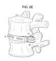
- the device of the present inventionis inserted into a disc space as shown.
- the deviceis in its closed (as shown in FIG. 2 a ).
- the closed configurationallows the device to pass through a minimally invasive portal.
- the deviceis inserted into the disc space in its closed configuration (as in FIGS. 2 b , 2 c , 2 d , 2 e ,).
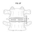
- the plates halvesare spread apart to put the device in its open position. This is shown in FIGS. 2 f , 2 g , and 2 h .
- the opened deviceare contacted to the vertebral bodies, as in FIG. 2 i.
- each plate halfcomprises a second end portion 35 having a screw-hole 37 .
- This through holeThe surgeon may pass a screw through this screw-hole in order to secure the plate half to an adjacent vertebral body.
- the devicefurther comprises d) a plurality of screws 39 (such as two screws), wherein the screws are received in the screw-holes, thereby bilaterally securing the plate halves to the sides of the adjacent vertebral bodies.
- each screwcomprises a lag feature.
- the devicepossesses features that are particularly suited to promote tissue sparing during a lateral approach.
- the anterior and posterior walls of the cagedefine a cage depth D C
- the platehas a depth D P
- the depth of the plateis not greater than the cage depth. This feature helps minimize the profile of the cage during insertion.
- the first side wall of the cagehas a convex nose 41 .
- This featureprovides for ease of insertion of the cage into a disc space.
- the flangesextend from the second side wall of the cage, and so are opposite the nose of the cage.
- the sidewalls of the cagedefine a cage width W C , and the width of the cage is at least two times the depth of the cage D C . This geometric relation particularly points out the long, thin nature of lateral cages.
- the cagefurther has at least one strut 43 extending through the central throughhole from the anterior wall and the posterior wall so as to define at least two chambers 45 in the central throughhole. This is a common feature of lateral cages that allows for the tight packing of bone graft in the central throughhole.
- the anterior wall and the posterior wall of the cageeach have at least one window 47 therein. These windows help promote bony fusion in and around the cage.
- the cagehas a height H C
- the plate halveshave a closed position defining a first height HC PH
- the height of the plate halves in the closed positionis no more than the height of the cage.
- the plate halveshave an open position to define have a second height HO PH
- the second height of the plate halves in the open positionis greater than the height of the cage.
- each plate halfpivots in a plane substantially parallel to the anterior or posterior wall of the cage. This allows the plate half to be fixed to a sidewall of the adjacent vertebral body and pivot in the frontal plane.
- the upper and lower surfaces of the cagemay be convex.
- eachis convex.
- the domed upper and lower surfacesprovide a closer congruence with the normal anatomical concavity of the vertebral endplates than do their flat counterparts.
- the anterior wall of the cageis convex in order to more closely correspond with the curved anterior rim of the vertebral body.
- the upper and lower surface of the cagehave teeth 101 for gripping the adjacent vertebral bodies (as shown in FIG. 1 a ).
- the device of the present inventioncomprises a single cross pin.
- each flangehas one through hole 33 .
- the devicemay further comprise:
- a locking mechanismmay be added to prevent rotation or micromotion once the plate halves are secured to the bone.
- a method of inserting the intervertebral fusion device of the present inventioncomprising the steps of:
- the insertion steptakes place through a portal such as a cannula.
- the cages of the present inventionmay be made from any non-resorbable material appropriate for human surgical implantation, including but not limited to, surgically appropriate metals, and non-metallic materials, such as carbon fiber composites, polymers and ceramics.
- the interbody devicesare preferably made out of PEEK or CFRP or any other suitable material providing adequate strength and radiolucency.
- implantable metalssuch as titanium or stainless steel components may be required to ensure adequate strength for either the interbody device.
- the interbody devicecan be made as a combination of PEEK and metal.
- resorbable materialssuch as polylactide, polyglycolide, and magnesium are preferred.
- the cage materialis selected from the group consisting of PEEK, ceramic and metallic.
- the cage materialis preferably selected from the group consisting of metal and composite (such as PEEK/carbon fiber).
- the metalis preferably selected from the group consisting of titanium, titanium alloys (such as Ti-6Al-4V), chrome alloys (such as CrCo or Cr—Co—Mo) and stainless steel.
- the polymeris preferably selected from the group consisting of polyesters, (particularly aromatic esters such as polyalkylene terephthalates, polyamides; polyalkenes; poly(vinyl fluoride); PTFE; polyarylethyl ketone PAEK; polyphenylene and mixtures thereof.
- the ceramicis preferably selected from the group consisting of alumina, zirconia and mixtures thereof. It is preferred to select an alumina-zirconia ceramic, such as BIOLOX DeltaTM, available from CeramTec of Plochingen, Germany.
- the cage membercomprises PEEK. In others, it is a ceramic.
- the first componentconsists essentially of a metallic material, preferably a titanium alloy or a chrome-cobalt alloy.
- the componentsare made of a stainless steel alloy, preferably BioDur® CCM Plus® Alloy available from Carpenter Specialty Alloys, Carpenter Technology Corporation of Wyomissing, Pa.
- the outer surfaces of the componentsare coated with a sintered beadcoating, preferably PorocoatTM, available from DePuy Orthopaedics of Warsaw, Ind.
- the componentsare made from a composite comprising carbon fiber.
- Composites comprising carbon fiberare advantageous in that they typically have a strength and stiffness that is superior to neat polymer materials such as a polyarylethyl ketone PAEK.
- each componentis made from a polymer composite such as a PEKK-carbon fiber composite.
- the composite comprising carbon fiberfurther comprises a polymer.
- the polymeris a polyarylethyl ketone (PAEK). More preferably, the PAEK is selected from the group consisting of polyetherether ketone (PEEK), polyether ketone ketone (PEKK) and polyether ketone (PEK). In preferred embodiments, the PAEK is PEEK.
- the carbon fibercomprises between 1 vol % and 60 vol % (more preferably, between 10 vol % and 50 vol %) of the composite.
- the polymer and carbon fibersare homogeneously mixed.
- the materialis a laminate.
- the carbon fiberis present in a chopped state.
- the chopped carbon fibershave a median length of between 1 mm and 12 mm, more preferably between 4.5 mm and 7.5 mm.
- the carbon fiberis present as continuous strands.
- the compositecomprises:
- polyarylethyl ketoneis selected from the group consisting of polyetherether ketone (PEEK), polyether ketone ketone (PEKK) and polyether ketone (PEK).
- the compositeconsists essentially of PAEK and carbon fiber. More preferably, the composite comprises 60-80 wt % PAEK and 20-40 wt % carbon fiber. Still more preferably the composite comprises 65-75 wt % PAEK and 25-35 wt % carbon fiber.
- the pin component of the present inventionis made from a biocompatible metal, such as stainless steel, chromium cobalt, or titanium alloy.
- the plate halves of the present inventionare made from a biocompatible metal, such as stainless steel, chromium cobalt, or titanium alloy.
- the method of using the present inventionis as follows:
- Step 1Assemble the cage/plate assembly to the inserter
- Step 2Insert the cage/plate assembly into the disc space
- Step 3Deploy open the plate (with either the inserter or a secondary instrument)
- Step 4Drill and tap holes through the plate
- Step 5Insert bone screws
- Step 6Tighten the locking mechanism
- the central throughhole of the cageis filled with a fusion material.
- This fusion materialpromotes bony fusion of the adjacent vertebral bodies through the disc space.
- the fusion materialmay be autograft bone marrow or allograft bone.
- the fusion materialmay be synthetic, such as tricalcium phosphate or hydroxyapatite.
- the fusion materialmay be a recombinant protein, such as a growth factor.
Landscapes
- Health & Medical Sciences (AREA)
- Engineering & Computer Science (AREA)
- Biomedical Technology (AREA)
- Neurology (AREA)
- Orthopedic Medicine & Surgery (AREA)
- Cardiology (AREA)
- Oral & Maxillofacial Surgery (AREA)
- Transplantation (AREA)
- Heart & Thoracic Surgery (AREA)
- Vascular Medicine (AREA)
- Life Sciences & Earth Sciences (AREA)
- Animal Behavior & Ethology (AREA)
- General Health & Medical Sciences (AREA)
- Public Health (AREA)
- Veterinary Medicine (AREA)
- Prostheses (AREA)
Abstract
Description
- a) an intervertebral fusion cage having an anterior wall, a posterior wall, first and second side walls connecting the anterior and posterior walls to form a central throughhole, an upper surface adapted for gripping an upper endplate and a lower surface adapted for gripping a lower endplate;
- b) a plate comprising first and second halves,
wherein each half of the plate is pivotally connected to the cage.
- a) an
intervertebral fusion cage 3 having ananterior wall 5, aposterior wall 7, first9 and second11 side walls connecting the anterior and posterior walls to form acentral throughhole 13, anupper surface 15 adapted for gripping an upper endplate and alower surface 17 adapted for gripping a lower endplate; - b) a
plate 19 comprising first21 and second23 halves,
wherein each half of the plate is pivotally connected to the cage.
- a) an
- c) first and second pins,
wherein the cage further comprises a pair of flanges, each flange having a first and second throughhole, wherein the first throughholes are aligned and wherein the second throughholes are aligned, wherein the first and second plate halves each has a first end portion having a throughhole,
wherein the first pin passes through the first througholes of the flanges and the throughhole of the first plate half.
wherein the second pin passes through the second througholes of the flanges and the throughhole of the second plate half.
- c) first and second pins,
- c) a
first pin 25,
wherein the cage further comprises a pair offlanges 27, each flange having a first throughhole, wherein the first throughholes are aligned, wherein the first and second plate halves each has afirst end portion 31 having a throughhole33, wherein the throughholes of each plate half are aligned, and
wherein the first pin passes through the througholes of the flanges and the throughholes of the plate halves.
- c) a
- a) inserting (preferably, either laterally or antero-laterally) the cage into a disc space with the plate halves in a closed configuration, and
- b) pivoting the plate halves into an open position.
Preferably, this method further comprises the step of c) securing the plate halves to the sides of adjacent vertebral bodies. Preferably, each plate half comprises a second end portion having a screwhole, and the securing step comprises passing a screw through each screw-whole and into a vertebral body.
- 40-99% (more preferably, 60-80 vol %) polyarylethyl ketone (PAEK), and
- 1-60% (more preferably, 20-40 vol %) carbon fiber,
Claims (17)
Priority Applications (3)
| Application Number | Priority Date | Filing Date | Title |
|---|---|---|---|
| US13/364,282US8852278B2 (en) | 2011-12-22 | 2012-02-01 | Lateral cage with integrated plate |
| EP12814074.6AEP2793758B1 (en) | 2011-12-22 | 2012-12-17 | Lateral fusion cage with integrated plate |
| PCT/US2012/070082WO2013096192A1 (en) | 2011-12-22 | 2012-12-17 | Lateral fusion cage with integrated plate |
Applications Claiming Priority (2)
| Application Number | Priority Date | Filing Date | Title |
|---|---|---|---|
| US201161579567P | 2011-12-22 | 2011-12-22 | |
| US13/364,282US8852278B2 (en) | 2011-12-22 | 2012-02-01 | Lateral cage with integrated plate |
Publications (2)
| Publication Number | Publication Date |
|---|---|
| US20130166027A1 US20130166027A1 (en) | 2013-06-27 |
| US8852278B2true US8852278B2 (en) | 2014-10-07 |
Family
ID=48655330
Family Applications (1)
| Application Number | Title | Priority Date | Filing Date |
|---|---|---|---|
| US13/364,282Active2032-09-27US8852278B2 (en) | 2011-12-22 | 2012-02-01 | Lateral cage with integrated plate |
Country Status (3)
| Country | Link |
|---|---|
| US (1) | US8852278B2 (en) |
| EP (1) | EP2793758B1 (en) |
| WO (1) | WO2013096192A1 (en) |
Cited By (10)
| Publication number | Priority date | Publication date | Assignee | Title |
|---|---|---|---|---|
| US9216096B2 (en) | 2010-03-16 | 2015-12-22 | Pinnacle Spine Group, Llc | Intervertebral implants and related tools |
| US9380932B1 (en) | 2011-11-02 | 2016-07-05 | Pinnacle Spine Group, Llc | Retractor devices for minimally invasive access to the spine |
| US20180221155A1 (en)* | 2012-08-03 | 2018-08-09 | Globus Medical, Inc. | Intervertebral implant |
| US10070970B2 (en) | 2013-03-14 | 2018-09-11 | Pinnacle Spine Group, Llc | Interbody implants and graft delivery systems |
| US20180303629A1 (en)* | 2017-04-20 | 2018-10-25 | Life Spine, Inc. | Lateral Spine Plate with Collapsible Vertebral Attachment Arms |
| US11026726B2 (en) | 2012-06-29 | 2021-06-08 | K2M, Inc. | Minimal-profile anterior cervical plate and cage apparatus and method of using same |
| USD974558S1 (en)* | 2020-12-18 | 2023-01-03 | Stryker European Operations Limited | Ultrasonic knife |
| US20230310169A1 (en)* | 2020-06-15 | 2023-10-05 | Nofusco Corporation | Implant system and methods of use |
| US11801061B2 (en) | 2012-12-08 | 2023-10-31 | Retrospine Pty Ltd | System and method for inserting an intervertebral cage into a spine |
| WO2023240032A3 (en)* | 2022-06-05 | 2024-02-29 | Foundation Surgical Group, Inc. | Implant system and methods of use |
Families Citing this family (26)
| Publication number | Priority date | Publication date | Assignee | Title |
|---|---|---|---|---|
| US9039768B2 (en) | 2006-12-22 | 2015-05-26 | Medos International Sarl | Composite vertebral spacers and instrument |
| US20090248092A1 (en) | 2008-03-26 | 2009-10-01 | Jonathan Bellas | Posterior Intervertebral Disc Inserter and Expansion Techniques |
| US9526620B2 (en) | 2009-03-30 | 2016-12-27 | DePuy Synthes Products, Inc. | Zero profile spinal fusion cage |
| US8287597B1 (en) | 2009-04-16 | 2012-10-16 | Nuvasive, Inc. | Method and apparatus for performing spine surgery |
| US9393129B2 (en) | 2009-12-10 | 2016-07-19 | DePuy Synthes Products, Inc. | Bellows-like expandable interbody fusion cage |
| US20120078372A1 (en) | 2010-09-23 | 2012-03-29 | Thomas Gamache | Novel implant inserter having a laterally-extending dovetail engagement feature |
| US11529241B2 (en) | 2010-09-23 | 2022-12-20 | DePuy Synthes Products, Inc. | Fusion cage with in-line single piece fixation |
| US20120078373A1 (en) | 2010-09-23 | 2012-03-29 | Thomas Gamache | Stand alone intervertebral fusion device |
| WO2013036707A1 (en) | 2011-09-09 | 2013-03-14 | Spine Wave, Inc. | Lateral approach expandable spinal implant and method |
| US9248028B2 (en) | 2011-09-16 | 2016-02-02 | DePuy Synthes Products, Inc. | Removable, bone-securing cover plate for intervertebral fusion cage |
| US9271836B2 (en)* | 2012-03-06 | 2016-03-01 | DePuy Synthes Products, Inc. | Nubbed plate |
| AU2013282268A1 (en) | 2012-06-29 | 2015-01-22 | DePuy Synthes Products, LLC | Lateral insertion spinal implant |
| US10182921B2 (en) | 2012-11-09 | 2019-01-22 | DePuy Synthes Products, Inc. | Interbody device with opening to allow packing graft and other biologics |
| GB2507965B (en)* | 2012-11-14 | 2018-12-19 | Steris Instrument Man Services Inc | Cage assembly for tibial tuberosity advancement procedure |
| US9283091B2 (en)* | 2013-10-07 | 2016-03-15 | Warsaw Orthopedic, Inc. | Spinal implant system and method |
| US9918848B2 (en)* | 2013-10-07 | 2018-03-20 | Warsaw Orthopedic, Inc. | Spinal implant system and method |
| DE102015101675B4 (en) | 2015-02-05 | 2019-03-21 | Mtm Medizintechnik Mauk Gmbh | implant |
| US10729554B2 (en)* | 2015-10-09 | 2020-08-04 | DePuy Synthes Products, Inc. | Expandable trials |
| FR3058043B1 (en)* | 2016-10-27 | 2020-11-13 | Ldr Medical | EXPANDABLE INTERSOMATIC CAGE |
| FR3058044A1 (en)* | 2016-10-27 | 2018-05-04 | Ldr Medical | EXPANDABLE INTERSOMATIC CAGE |
| US10624760B2 (en)* | 2017-05-22 | 2020-04-21 | Warsaw Orthopedic, Inc. | Spinal implant system and method |
| US10940016B2 (en) | 2017-07-05 | 2021-03-09 | Medos International Sarl | Expandable intervertebral fusion cage |
| KR102261812B1 (en)* | 2019-06-03 | 2021-06-08 | 경북대학교 산학협력단 | Spinal Fixation Device |
| KR20220017092A (en)* | 2020-08-04 | 2022-02-11 | 임병철 | Intervertebral cage |
| KR102392505B1 (en)* | 2020-08-04 | 2022-04-28 | 임병철 | Intervertebral cage |
| EP4282355A4 (en)* | 2021-02-26 | 2025-01-08 | Kyungpook National University Industry-Academic Cooperation Foundation | SPINAL FIXATION DEVICE |
Citations (40)
| Publication number | Priority date | Publication date | Assignee | Title |
|---|---|---|---|---|
| US6432106B1 (en) | 1999-11-24 | 2002-08-13 | Depuy Acromed, Inc. | Anterior lumbar interbody fusion cage with locking plate |
| US6695846B2 (en) | 2002-03-12 | 2004-02-24 | Spinal Innovations, Llc | Bone plate and screw retaining mechanism |
| US6890335B2 (en) | 2001-08-24 | 2005-05-10 | Zimmer Spine, Inc. | Bone fixation device |
| US7112222B2 (en) | 2003-03-31 | 2006-09-26 | Depuy Spine, Inc. | Anterior lumbar interbody fusion cage with locking plate |
| US20060241597A1 (en)* | 2004-12-13 | 2006-10-26 | St. Francis Medical Technologies, Inc. | Inter-cervical facet joint implant with locking screw system |
| US20070049941A1 (en) | 2005-08-25 | 2007-03-01 | Lanx, Llc | Plate with stabilization |
| US20070233118A1 (en) | 2006-03-02 | 2007-10-04 | The Cleveland Clinic Foundation | Cervical fusion apparatus and method for use |
| US7288095B2 (en) | 2004-08-12 | 2007-10-30 | Atlas Spine, Inc. | Bone plate with screw lock |
| US7288094B2 (en) | 2005-06-10 | 2007-10-30 | Sdgi Holdings, Inc. | System and method for retaining screws relative to a vertebral plate |
| US7306605B2 (en) | 2003-10-02 | 2007-12-11 | Zimmer Spine, Inc. | Anterior cervical plate |
| US7341590B2 (en) | 2001-03-27 | 2008-03-11 | Nuvasive, Inc. | Hinged anterior thoracic/lumbar plate |
| US7438715B2 (en) | 2005-01-06 | 2008-10-21 | Spinal Llc | Spinal implant kit |
| US20080294262A1 (en) | 2005-12-05 | 2008-11-27 | Jerome Levieux | Cages for Setting and Intersomatically Fusing Vertebrae |
| US20080300634A1 (en) | 2007-05-31 | 2008-12-04 | Wayne Gray | Spinal interbody system and method |
| WO2009025841A1 (en) | 2007-08-20 | 2009-02-26 | Nuvasive, Inc. | Surgical fixation system and related methods |
| US7594931B2 (en) | 2001-07-13 | 2009-09-29 | Ldr Medical | Vertebral cage device with modular fixation |
| US7641665B2 (en) | 2003-03-06 | 2010-01-05 | Spinecore, Inc. | Instrumentation and methods for use in implementing a cervical disc replacement device |
| US20100004747A1 (en) | 2008-07-07 | 2010-01-07 | Jin-Fu Lin | Trans-Vertebral and Intra-Vertebral Plate and Fusion Cage Device for Spinal Interbody Fusion and Method of Operation |
| US20100016901A1 (en) | 2005-06-16 | 2010-01-21 | Robinson James C | Bone screw retaining system |
| US20100042159A1 (en) | 2008-07-17 | 2010-02-18 | Alphatec Spine, Inc. | Bone plate assembly |
| US7674279B2 (en) | 2006-10-13 | 2010-03-09 | Spinal U.S.A. | Bone plate |
| US7704255B2 (en) | 1997-02-11 | 2010-04-27 | Warsaw Orthopedic, Inc. | Threadless multi-lock anterior cervical plating system |
| US20100249937A1 (en)* | 2009-03-27 | 2010-09-30 | Spinal Elements, Inc. | Flanged interbody fusion device |
| US20100292737A1 (en) | 2009-05-15 | 2010-11-18 | Sean Suh | Orthopedic Plate Blocking Assembly |
| US20100292696A1 (en) | 2005-06-06 | 2010-11-18 | Christophe Chantelot | Device for Securing to a Support, Assembling Piece for this Device, and Method for Securing a Device to a Support |
| US20100305704A1 (en) | 2006-02-27 | 2010-12-02 | Synthes Gmbh | Intervertebral implant with fixation geometry |
| US7862616B2 (en) | 2003-02-06 | 2011-01-04 | Synthes Usa, Llc | Intervertebral implant |
| US20110009908A1 (en) | 2006-04-28 | 2011-01-13 | Joe Ferguson | Orthopedic support locating or centering feature and method |
| US20110008864A1 (en) | 2008-03-28 | 2011-01-13 | Novozymes North America, Inc. | Processes for Producing Fermentation Products |
| US20110015745A1 (en)* | 2009-07-14 | 2011-01-20 | Bucci Kara A | Combined Spinal Interbody and Plate Assemblies |
| US7875062B2 (en) | 2006-03-07 | 2011-01-25 | Warsaw Orthopedic, Inc. | Methods and devices for retaining bone plate anchors |
| US7887595B1 (en) | 2005-12-05 | 2011-02-15 | Nuvasive, Inc. | Methods and apparatus for spinal fusion |
| US20110082550A1 (en) | 2009-10-07 | 2011-04-07 | Yeh An-Shih | Intervertebral fixation device |
| US20110106159A1 (en) | 2008-06-05 | 2011-05-05 | Seaspine, Inc. | Spinal fixation plate assembly |
| WO2011080535A1 (en) | 2009-12-31 | 2011-07-07 | Lrd Medical | Anchoring device, intervertebral implant and implantation instrument |
| US20110184415A1 (en) | 2010-01-26 | 2011-07-28 | Westmark Medical, Llc | Bone screw retention mechanism |
| US8002808B2 (en) | 2002-11-22 | 2011-08-23 | Warsaw Orthopedic, Inc. | Variable angle adaptive plate |
| US8007523B2 (en) | 1997-08-04 | 2011-08-30 | Zimmer Spine, Inc. | System and method for stabilizing the human spine with a bone plate |
| US20110213421A1 (en) | 2004-04-19 | 2011-09-01 | Lawrence Binder | Bone Fixation Plate |
| US20110251689A1 (en) | 2010-04-08 | 2011-10-13 | Seifert Jody L | Intervertebral Implant |
- 2012
- 2012-02-01USUS13/364,282patent/US8852278B2/enactiveActive
- 2012-12-17WOPCT/US2012/070082patent/WO2013096192A1/enactiveApplication Filing
- 2012-12-17EPEP12814074.6Apatent/EP2793758B1/enactiveActive
Patent Citations (41)
| Publication number | Priority date | Publication date | Assignee | Title |
|---|---|---|---|---|
| US7704255B2 (en) | 1997-02-11 | 2010-04-27 | Warsaw Orthopedic, Inc. | Threadless multi-lock anterior cervical plating system |
| US8007523B2 (en) | 1997-08-04 | 2011-08-30 | Zimmer Spine, Inc. | System and method for stabilizing the human spine with a bone plate |
| US6432106B1 (en) | 1999-11-24 | 2002-08-13 | Depuy Acromed, Inc. | Anterior lumbar interbody fusion cage with locking plate |
| US7341590B2 (en) | 2001-03-27 | 2008-03-11 | Nuvasive, Inc. | Hinged anterior thoracic/lumbar plate |
| US7594931B2 (en) | 2001-07-13 | 2009-09-29 | Ldr Medical | Vertebral cage device with modular fixation |
| US6890335B2 (en) | 2001-08-24 | 2005-05-10 | Zimmer Spine, Inc. | Bone fixation device |
| US6695846B2 (en) | 2002-03-12 | 2004-02-24 | Spinal Innovations, Llc | Bone plate and screw retaining mechanism |
| US8002808B2 (en) | 2002-11-22 | 2011-08-23 | Warsaw Orthopedic, Inc. | Variable angle adaptive plate |
| US7862616B2 (en) | 2003-02-06 | 2011-01-04 | Synthes Usa, Llc | Intervertebral implant |
| US7641665B2 (en) | 2003-03-06 | 2010-01-05 | Spinecore, Inc. | Instrumentation and methods for use in implementing a cervical disc replacement device |
| US7112222B2 (en) | 2003-03-31 | 2006-09-26 | Depuy Spine, Inc. | Anterior lumbar interbody fusion cage with locking plate |
| US7306605B2 (en) | 2003-10-02 | 2007-12-11 | Zimmer Spine, Inc. | Anterior cervical plate |
| US20110213421A1 (en) | 2004-04-19 | 2011-09-01 | Lawrence Binder | Bone Fixation Plate |
| US7288095B2 (en) | 2004-08-12 | 2007-10-30 | Atlas Spine, Inc. | Bone plate with screw lock |
| US20060241597A1 (en)* | 2004-12-13 | 2006-10-26 | St. Francis Medical Technologies, Inc. | Inter-cervical facet joint implant with locking screw system |
| US20060247650A1 (en)* | 2004-12-13 | 2006-11-02 | St. Francis Medical Technologies, Inc. | Inter-cervical facet joint fusion implant |
| US7438715B2 (en) | 2005-01-06 | 2008-10-21 | Spinal Llc | Spinal implant kit |
| US20100292696A1 (en) | 2005-06-06 | 2010-11-18 | Christophe Chantelot | Device for Securing to a Support, Assembling Piece for this Device, and Method for Securing a Device to a Support |
| US7288094B2 (en) | 2005-06-10 | 2007-10-30 | Sdgi Holdings, Inc. | System and method for retaining screws relative to a vertebral plate |
| US20100016901A1 (en) | 2005-06-16 | 2010-01-21 | Robinson James C | Bone screw retaining system |
| US20070049941A1 (en) | 2005-08-25 | 2007-03-01 | Lanx, Llc | Plate with stabilization |
| US7887595B1 (en) | 2005-12-05 | 2011-02-15 | Nuvasive, Inc. | Methods and apparatus for spinal fusion |
| US20080294262A1 (en) | 2005-12-05 | 2008-11-27 | Jerome Levieux | Cages for Setting and Intersomatically Fusing Vertebrae |
| US20100305704A1 (en) | 2006-02-27 | 2010-12-02 | Synthes Gmbh | Intervertebral implant with fixation geometry |
| US20070233118A1 (en) | 2006-03-02 | 2007-10-04 | The Cleveland Clinic Foundation | Cervical fusion apparatus and method for use |
| US7875062B2 (en) | 2006-03-07 | 2011-01-25 | Warsaw Orthopedic, Inc. | Methods and devices for retaining bone plate anchors |
| US20110009908A1 (en) | 2006-04-28 | 2011-01-13 | Joe Ferguson | Orthopedic support locating or centering feature and method |
| US7674279B2 (en) | 2006-10-13 | 2010-03-09 | Spinal U.S.A. | Bone plate |
| US20080300634A1 (en) | 2007-05-31 | 2008-12-04 | Wayne Gray | Spinal interbody system and method |
| WO2009025841A1 (en) | 2007-08-20 | 2009-02-26 | Nuvasive, Inc. | Surgical fixation system and related methods |
| US20110008864A1 (en) | 2008-03-28 | 2011-01-13 | Novozymes North America, Inc. | Processes for Producing Fermentation Products |
| US20110106159A1 (en) | 2008-06-05 | 2011-05-05 | Seaspine, Inc. | Spinal fixation plate assembly |
| US20100004747A1 (en) | 2008-07-07 | 2010-01-07 | Jin-Fu Lin | Trans-Vertebral and Intra-Vertebral Plate and Fusion Cage Device for Spinal Interbody Fusion and Method of Operation |
| US20100042159A1 (en) | 2008-07-17 | 2010-02-18 | Alphatec Spine, Inc. | Bone plate assembly |
| US20100249937A1 (en)* | 2009-03-27 | 2010-09-30 | Spinal Elements, Inc. | Flanged interbody fusion device |
| US20100292737A1 (en) | 2009-05-15 | 2010-11-18 | Sean Suh | Orthopedic Plate Blocking Assembly |
| US20110015745A1 (en)* | 2009-07-14 | 2011-01-20 | Bucci Kara A | Combined Spinal Interbody and Plate Assemblies |
| US20110082550A1 (en) | 2009-10-07 | 2011-04-07 | Yeh An-Shih | Intervertebral fixation device |
| WO2011080535A1 (en) | 2009-12-31 | 2011-07-07 | Lrd Medical | Anchoring device, intervertebral implant and implantation instrument |
| US20110184415A1 (en) | 2010-01-26 | 2011-07-28 | Westmark Medical, Llc | Bone screw retention mechanism |
| US20110251689A1 (en) | 2010-04-08 | 2011-10-13 | Seifert Jody L | Intervertebral Implant |
Non-Patent Citations (1)
| Title |
|---|
| Search Report and Written Opinion dated Apr. 11, 2013 from corresponding PCT/US2012/070082. |
Cited By (18)
| Publication number | Priority date | Publication date | Assignee | Title |
|---|---|---|---|---|
| US9216096B2 (en) | 2010-03-16 | 2015-12-22 | Pinnacle Spine Group, Llc | Intervertebral implants and related tools |
| US9649203B2 (en) | 2010-03-16 | 2017-05-16 | Pinnacle Spine Group, Llc | Methods of post-filling an intervertebral implant |
| US9788973B2 (en) | 2010-03-16 | 2017-10-17 | Pinnacle Spine Group, Llc | Spinal implant |
| US9380932B1 (en) | 2011-11-02 | 2016-07-05 | Pinnacle Spine Group, Llc | Retractor devices for minimally invasive access to the spine |
| US11026726B2 (en) | 2012-06-29 | 2021-06-08 | K2M, Inc. | Minimal-profile anterior cervical plate and cage apparatus and method of using same |
| US10973653B2 (en)* | 2012-08-03 | 2021-04-13 | Globus Medical, Inc. | Intervertebral implant |
| US20180221155A1 (en)* | 2012-08-03 | 2018-08-09 | Globus Medical, Inc. | Intervertebral implant |
| US11801061B2 (en) | 2012-12-08 | 2023-10-31 | Retrospine Pty Ltd | System and method for inserting an intervertebral cage into a spine |
| US11944323B2 (en) | 2012-12-08 | 2024-04-02 | Retrospine Pty Ltd | Surgical tool |
| US10070970B2 (en) | 2013-03-14 | 2018-09-11 | Pinnacle Spine Group, Llc | Interbody implants and graft delivery systems |
| US20180303629A1 (en)* | 2017-04-20 | 2018-10-25 | Life Spine, Inc. | Lateral Spine Plate with Collapsible Vertebral Attachment Arms |
| US10849763B2 (en)* | 2017-04-20 | 2020-12-01 | Life Spine, Inc. | Lateral spine plate with collapsible vertebral attachment arms |
| US11712343B2 (en) | 2017-04-20 | 2023-08-01 | Life Spine, Inc. | Lateral spine plate with collapsible vertebral attachment arms |
| US20230310169A1 (en)* | 2020-06-15 | 2023-10-05 | Nofusco Corporation | Implant system and methods of use |
| US12144742B2 (en)* | 2020-06-15 | 2024-11-19 | Foundation Surgical Group, Inc. | Implant system and methods of use |
| USD974558S1 (en)* | 2020-12-18 | 2023-01-03 | Stryker European Operations Limited | Ultrasonic knife |
| USD1045078S1 (en) | 2020-12-18 | 2024-10-01 | Stryker European Operations Limited | Ultrasonic knife |
| WO2023240032A3 (en)* | 2022-06-05 | 2024-02-29 | Foundation Surgical Group, Inc. | Implant system and methods of use |
Also Published As
| Publication number | Publication date |
|---|---|
| US20130166027A1 (en) | 2013-06-27 |
| WO2013096192A1 (en) | 2013-06-27 |
| EP2793758B1 (en) | 2017-11-01 |
| EP2793758A1 (en) | 2014-10-29 |
Similar Documents
| Publication | Publication Date | Title |
|---|---|---|
| US8852278B2 (en) | Lateral cage with integrated plate | |
| US11844702B2 (en) | Nubbed plate | |
| US10646350B2 (en) | Multi-segment lateral cages adapted to flex substantially in the coronal plane | |
| US9579215B2 (en) | Distractible intervertebral implant | |
| US11529241B2 (en) | Fusion cage with in-line single piece fixation | |
| US20160100954A1 (en) | Fusion device and associated methods | |
| US20140172103A1 (en) | Polyaxial Intervertebral Cage | |
| US20100137916A1 (en) | Spinal plates for stabilizing segments | |
| US20130218277A1 (en) | Interbody fusion device | |
| EP2618788B1 (en) | Multi-segment lateral cages adapted to flex substantially in the coronal plane |
Legal Events
| Date | Code | Title | Description |
|---|---|---|---|
| AS | Assignment | Owner name:DEPUY SPINE, INC., MASSACHUSETTS Free format text:ASSIGNMENT OF ASSIGNORS INTEREST;ASSIGNOR:BELLAS, JONATHAN;REEL/FRAME:029181/0522 Effective date:20120621 | |
| AS | Assignment | Owner name:HAND INNOVATIONS LLC, FLORIDA Free format text:ASSIGNMENT OF ASSIGNORS INTEREST;ASSIGNOR:DEPUY SPINE, LLC;REEL/FRAME:030352/0709 Effective date:20121230 Owner name:DEPUY SPINE, LLC, MASSACHUSETTS Free format text:CHANGE OF NAME;ASSIGNOR:DEPUY SPINE, INC.;REEL/FRAME:030352/0673 Effective date:20121230 Owner name:DEPUY SYNTHES PRODUCTS, LLC, MASSACHUSETTS Free format text:CHANGE OF NAME;ASSIGNOR:HAND INNOVATIONS LLC;REEL/FRAME:030352/0722 Effective date:20121231 | |
| STCF | Information on status: patent grant | Free format text:PATENTED CASE | |
| MAFP | Maintenance fee payment | Free format text:PAYMENT OF MAINTENANCE FEE, 4TH YEAR, LARGE ENTITY (ORIGINAL EVENT CODE: M1551) Year of fee payment:4 | |
| MAFP | Maintenance fee payment | Free format text:PAYMENT OF MAINTENANCE FEE, 8TH YEAR, LARGE ENTITY (ORIGINAL EVENT CODE: M1552); ENTITY STATUS OF PATENT OWNER: LARGE ENTITY Year of fee payment:8 |