US8851715B2 - Lamp ventilation system - Google Patents
Lamp ventilation systemDownload PDFInfo
- Publication number
- US8851715B2 US8851715B2US13/350,550US201213350550AUS8851715B2US 8851715 B2US8851715 B2US 8851715B2US 201213350550 AUS201213350550 AUS 201213350550AUS 8851715 B2US8851715 B2US 8851715B2
- Authority
- US
- United States
- Prior art keywords
- channel
- opening
- housing
- lighting module
- plane
- Prior art date
- Legal status (The legal status is an assumption and is not a legal conclusion. Google has not performed a legal analysis and makes no representation as to the accuracy of the status listed.)
- Active, expires
Links
Images


Classifications
- F—MECHANICAL ENGINEERING; LIGHTING; HEATING; WEAPONS; BLASTING
- F21—LIGHTING
- F21V—FUNCTIONAL FEATURES OR DETAILS OF LIGHTING DEVICES OR SYSTEMS THEREOF; STRUCTURAL COMBINATIONS OF LIGHTING DEVICES WITH OTHER ARTICLES, NOT OTHERWISE PROVIDED FOR
- F21V29/00—Protecting lighting devices from thermal damage; Cooling or heating arrangements specially adapted for lighting devices or systems
- F21V29/50—Cooling arrangements
- F21V29/60—Cooling arrangements characterised by the use of a forced flow of gas, e.g. air
- F21V29/67—Cooling arrangements characterised by the use of a forced flow of gas, e.g. air characterised by the arrangement of fans
- F21V29/677—Cooling arrangements characterised by the use of a forced flow of gas, e.g. air characterised by the arrangement of fans the fans being used for discharging
- F—MECHANICAL ENGINEERING; LIGHTING; HEATING; WEAPONS; BLASTING
- F21—LIGHTING
- F21V—FUNCTIONAL FEATURES OR DETAILS OF LIGHTING DEVICES OR SYSTEMS THEREOF; STRUCTURAL COMBINATIONS OF LIGHTING DEVICES WITH OTHER ARTICLES, NOT OTHERWISE PROVIDED FOR
- F21V29/00—Protecting lighting devices from thermal damage; Cooling or heating arrangements specially adapted for lighting devices or systems
- F21V29/50—Cooling arrangements
- F21V29/70—Cooling arrangements characterised by passive heat-dissipating elements, e.g. heat-sinks
- F21V29/74—Cooling arrangements characterised by passive heat-dissipating elements, e.g. heat-sinks with fins or blades
- F21V29/76—Cooling arrangements characterised by passive heat-dissipating elements, e.g. heat-sinks with fins or blades with essentially identical parallel planar fins or blades, e.g. with comb-like cross-section
- F—MECHANICAL ENGINEERING; LIGHTING; HEATING; WEAPONS; BLASTING
- F21—LIGHTING
- F21V—FUNCTIONAL FEATURES OR DETAILS OF LIGHTING DEVICES OR SYSTEMS THEREOF; STRUCTURAL COMBINATIONS OF LIGHTING DEVICES WITH OTHER ARTICLES, NOT OTHERWISE PROVIDED FOR
- F21V29/00—Protecting lighting devices from thermal damage; Cooling or heating arrangements specially adapted for lighting devices or systems
- F21V29/50—Cooling arrangements
- F21V29/70—Cooling arrangements characterised by passive heat-dissipating elements, e.g. heat-sinks
- F21V29/83—Cooling arrangements characterised by passive heat-dissipating elements, e.g. heat-sinks the elements having apertures, ducts or channels, e.g. heat radiation holes
- F—MECHANICAL ENGINEERING; LIGHTING; HEATING; WEAPONS; BLASTING
- F21—LIGHTING
- F21Y—INDEXING SCHEME ASSOCIATED WITH SUBCLASSES F21K, F21L, F21S and F21V, RELATING TO THE FORM OR THE KIND OF THE LIGHT SOURCES OR OF THE COLOUR OF THE LIGHT EMITTED
- F21Y2115/00—Light-generating elements of semiconductor light sources
- F21Y2115/10—Light-emitting diodes [LED]
Definitions
- Solid-state light emitterssuch as light emitting diodes (LEDs) and laser diodes, have several advantages over using more traditional arc lamps during curing processes, such as ultraviolet (UV) curing processes.
- Solid-state light emittersgenerally use less power, generate less heat, produce a higher quality cure, and have higher reliability than the traditional arc lamps. Some modifications increase the effectiveness and efficiency of the solid-state light emitters even further.
- solid-state light emittersemit less heat than their arc lamp counterparts, the temperatures emitted from the solid-state light emitters are still very high and can cause overheating of the solid-state light emitters during use and damage to the components of the solid-state light emitters over time. Overheating and damage to the components of the solid-state light emitters causes significant amounts of downtime for repair and loss of revenue.
- Some solid-state light emitterstry to incorporate cooling systems to remove some of the heat that is generated when the solid-state light emitter emits light.
- these cooling systemsinclude ventilation systems that have air intake and/or air exhaust openings positioned near the window through which light is emitted from the solid-state light emitter. This configuration positions the ventilation openings and causes air movement near the item(s) being cured. When ink is being cured on a medium, for example, this air movement disturbs the ink curing process and decreases the precision of positioning ink on the medium.
- These cooling systemstend to require large perimeters of space around the solid-state light emitters and prevent multiple solid-state light emitters from being stacked next to each other or on top of each other. Because of the ventilation challenges and the space restrictions for the solid-state light emitters, the light curing process is sometimes inefficient and expensive.
- FIG. 1shows a front perspective view of a lighting module, according to aspects of the disclosure.
- FIG. 2shows a back perspective view of the lighting module of FIG. 1 that shows openings to three channels in the housing.
- FIG. 3shows an alternative embodiment of the lighting module of FIG. 2 in which openings to two of the channels are positioned on the back surface of the housing and the opening to the third channel is located on the top surface of the housing.
- FIG. 4shows the interior of the housing of the lighting module shown in FIGS. 1 and 2 .
- FIG. 5shows a top view of the airflow pattern into and out of the housing of the lighting module illustrated in FIGS. 1 and 2 .
- FIG. 6shows the lighting module of FIGS. 1 , 2 , 4 , and 5 with baffles between the openings of the channels, according to aspects of the disclosure.
- FIG. 7shows an alternative embodiment of the lighting module, according to aspects of the disclosure.
- FIG. 8shows a back perspective view of multiple lighting modules in a stacked configuration.
- FIGS. 1 and 2show front and back perspective views, respectively, of a lighting module 100 having a housing 102 and an array of light-emitting elements positioned within the housing 102 .
- the housing 102can take any suitable shape, the housing 102 shown in FIGS. 1 and 2 is a rectangular box having a front surface 104 , an opposing back surface 106 , a top surface 108 , an opposing bottom surface 110 , and two opposing side surfaces 112 , 114 .
- the array of light-emitting elementsemits light through a window 116 on the front surface 104 of the housing 102 .
- the opposite, back surface 106 of the housing 102defines a plane on which three openings 118 , 120 , 122 are positioned that correspond to three adjacent channels defined within the housing 102 .
- the two outer openings 118 , 120correspond to air intake channels within the housing while the middle opening 122 corresponds to an air exhaust channel.
- FIG. 3shows an alternative embodiment in which two channel openings 124 , 126 are positioned on the back surface 106 of the housing 102 and a third channel opening 128 is positioned on the top surface 108 of the housing 102 near the end of the top surface 108 closest to the back surface 106 of the housing 102 .
- the two channel openings 124 , 126 on the back surface 106correspond to two air intake channels within the housing while the third channel opening on the top surface 108 corresponds to an air exhaust channel.
- the air exhaust channelis positioned between the two air intake channels and all three channels are adjacent and parallel to each other.
- the openings 118 , 120 , 122 in FIG. 4are all located on the same plane at respective ends 130 , 132 , 134 of the channels 136 , 138 , 140 defined in the housing 102 .
- Three channels 136 , 138 , 140are defined in the lighting module 100 shown in FIG. 4 , although any suitable number of channels may be included in alternative examples.
- the lighting module 100 of FIG. 4shows three, parallel and adjacent channels 136 , 138 , 140 , each having respective openings 118 , 120 , 122 at one end 130 , 132 , 134 .
- the channels 136 , 138 , 140are separated by partitions 142 in the example shown in FIG. 4 , although the channels 136 , 138 , 140 may be separated by any other suitable structure in alternative configurations.
- the partitions 142extend from the interior of the bottom surface 110 to the interior of the top surface 108 of the housing 102 , which creates enclosed channels through which air flows.
- the air entering the air intake channels 136 , 138is generally cooler than the air forced out of or generally expelled from the air exhaust channel 140 and the mixing of air entering and exiting channels 136 , 138 , 140 is undesired.
- the partitions 142separate the channels 136 , 138 , 140 and prevent air from mixing between the channels 136 , 138 , 140 within the housing 102 .
- the volume of each channel 136 , 138 , 140is approximately equal or the same in the lighting module 100 shown in FIG. 4 , although the channels' volume may be different in alternative configurations.
- All of the openings 118 , 120 , 122 in the example shown in FIG. 4are positioned along the plane defined by the back surface 106 of the housing 102 .
- the two outer channelsare air intake channels 136 , 138 and have one intake fan 144 positioned within each of their respective channels 136 , 138 such that each intake fan 144 causes air to enter each of these channels 136 , 138 through their respective openings 118 , 120 on the back surface 106 of the housing 102 .
- the air intake fans 144force the air that enters through the first intake opening 118 through the first, intake channel 136 and into a light-emitting element portion 148 of the housing where the array of light-emitting elements is housed along with a heat sink 150 .
- the housing 102is generally divided into two portions, the light-emitting element 148 portion that houses the array of light-emitting elements and the heat sink and a channel portion that includes all of the channels 136 , 138 , 140 .
- the heat sink 150transforms the heat generated by the array of light-emitting elements into air.
- the air from the intake channels 136 , 138is forced over and cools the hot air created by the heat sink 150 and exits the light-emitting element portion 148 through the middle, exhaust channel 140 .
- An exhaust fan 146 located in the exhaust channel 140forces air out of the light-emitting element portion 148 through the exhaust channel 140 and out of the lighting module 100 through the exhaust channel's opening 122 .
- the arrows in FIG. 5show this air flow pathway through the lighting module 100 .
- FIG. 6shows the lighting module 100 shown in FIG. 4 with the addition of two baffles 152 that are positioned between each opening 118 , 120 , 122 , although any number of baffles may be included.
- the baffles 152separate the air intake openings 118 , 120 from the air exhaust opening 122 to further prevent mixing of the warm or hot air that is forced out of or expelled from the air exhaust channel 140 through its opening 122 with the cooler air that enters through the air intake openings 118 , 120 and into the air intake channels 136 , 138 .
- the baffles 152are any suitable shape and size.
- the baffles 152have two surfaces 154 , 156 that are angled with respect to each other.
- the intake 144 and exhaust 146 fansare positioned within each of their respective channels 136 , 138 , 140 .
- the two air intake fans 144are aligned with each other and are positioned at the ends 158 , 160 of the channels 136 , 138 that are opposite the air intake openings 118 , 120 .
- the air exhaust fan 146is positioned near, although spaced apart from the end 162 of the channel 140 that is opposite the air exhaust opening 122 and defines a gap 164 between the air exhaust fan 146 and the end 162 of the air exhaust channel 140 .
- the two air intake fans 144are offset from or otherwise not in alignment with the air exhaust fan 146 .
- the two air intake fans 144 and the exhaust fan 146are all aligned with each other at the end 158 , 160 , 162 of their respective channels 136 , 138 , 140 that is opposite their respective openings 118 , 120 , 122 , as shown in FIG. 7 .
- the fansmay be aligned or offset from each other in any suitable manner and any number of fans may be included in the lighting module.
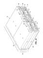
- FIG. 8shows a back perspective view of multiple lighting modules in a stacked configuration.
- Four lighting modules 158 , 160 , 162 , 164are shown stacked closely together both vertically and horizontally.
- the openings 118 , 120 , 122 of each of the lighting modules 158 , 160 , 162 , and 164are all positioned on the back surface 106 of their respective lighting modules.
- the lighting modules 158 , 160 , 162 , 164may be stacked in both a horizontal and a vertical direction without interfering with the ventilation systems of neighboring lighting modules. Any suitable number of lighting modules may be stacked in a vertical and/or a horizontal direction.
- Light emitted from the lighting modules 158 , 160 , 162 , 164cures an item, such as ink, on a medium 166 , as shown in FIG. 8 . Because of the relative proximity within which the lighting modules 158 , 160 , 162 , 164 can be positioned, light emitted from each of the lighting modules 158 , 160 , 162 , 164 can cure a smaller, more concentrated area, which increases the efficiency and/or decreases the amount of time that the curing processes require. Further, because the lighting modules can be stacked in any suitable configuration, the curing process that takes place on the medium can be customized by shape, length, width, and the like, which produces a more accurate and efficient curing process.
- Airis caused to enter a housing of a lighting module through an opening defined in an end of a channel and to flow through the channel into a light-emitting element portion of the housing.
- the light-emitting element portion of the housingmay be a chamber divided from the channels in the housing by a divider such as a partition, wall, or the like, although some alternative configurations do not include a physical barrier.
- the light-emitting element portion of the housingcontains an array of light-emitting elements and a heat sink that is arranged to remove heat generated when the array of light-emitting elements emit light.
- Airis also caused to enter the housing through a second opening that is defined in an end of a second channel. The second opening is positioned on a common plane with the other opening. The air entering the second channel flows through the second channel into the light-emitting element portion of the housing.
- the air entering the lighting module through the first and second openingflows through the first and second channels and into the light-emitting element portion and is forced across the heat sink and through a third channel that is parallel with and positioned between the air intake channels.
- the air that is forced into the third channelis expelled through a third opening defined in an end of the third channel and positioned on the same plane as the openings to the air intake channels.
- the air entering the air intake channels, the first and second channels in this examplegenerally has a lower temperature than the air that is expelled through the third opening of the third channel.
- the common plane on which the three openings to the three channels are positionedis opposite of a plane through which the array of light-emitting elements emit light.
Landscapes
- Engineering & Computer Science (AREA)
- General Engineering & Computer Science (AREA)
- Arrangement Of Elements, Cooling, Sealing, Or The Like Of Lighting Devices (AREA)
- Cooling Or The Like Of Electrical Apparatus (AREA)
Abstract
Description
Claims (20)
Priority Applications (6)
| Application Number | Priority Date | Filing Date | Title |
|---|---|---|---|
| US13/350,550US8851715B2 (en) | 2012-01-13 | 2012-01-13 | Lamp ventilation system |
| CN201390000187.4UCN204201836U (en) | 2012-01-13 | 2013-01-10 | Lighting module |
| KR2020147000030UKR200485060Y1 (en) | 2012-01-13 | 2013-01-10 | Lamp ventilation system |
| PCT/US2013/021046WO2013106579A1 (en) | 2012-01-13 | 2013-01-10 | Lamp ventilation system |
| DE212013000050.2UDE212013000050U1 (en) | 2012-01-13 | 2013-01-10 | Lamp ventilation system |
| TW102101087ATWI580897B (en) | 2012-01-13 | 2013-01-11 | Lamp ventilation system |
Applications Claiming Priority (1)
| Application Number | Priority Date | Filing Date | Title |
|---|---|---|---|
| US13/350,550US8851715B2 (en) | 2012-01-13 | 2012-01-13 | Lamp ventilation system |
Publications (2)
| Publication Number | Publication Date |
|---|---|
| US20130182436A1 US20130182436A1 (en) | 2013-07-18 |
| US8851715B2true US8851715B2 (en) | 2014-10-07 |
Family
ID=48779825
Family Applications (1)
| Application Number | Title | Priority Date | Filing Date |
|---|---|---|---|
| US13/350,550Active2032-11-16US8851715B2 (en) | 2012-01-13 | 2012-01-13 | Lamp ventilation system |
Country Status (6)
| Country | Link |
|---|---|
| US (1) | US8851715B2 (en) |
| KR (1) | KR200485060Y1 (en) |
| CN (1) | CN204201836U (en) |
| DE (1) | DE212013000050U1 (en) |
| TW (1) | TWI580897B (en) |
| WO (1) | WO2013106579A1 (en) |
Families Citing this family (6)
| Publication number | Priority date | Publication date | Assignee | Title |
|---|---|---|---|---|
| US8915624B2 (en)* | 2012-05-22 | 2014-12-23 | Cooper Technologies Company | Cooling heat-generating components of a light fixture |
| EP2927579B1 (en)* | 2014-04-04 | 2020-02-12 | Harman Professional Denmark ApS | Cooling module for led light fixture |
| JP5940116B2 (en)* | 2014-07-18 | 2016-06-29 | Hoya Candeo Optronics株式会社 | Light irradiation device |
| JP6126149B2 (en)* | 2015-02-26 | 2017-05-10 | ファナック株式会社 | Air-cooled laser apparatus provided with a heat conducting member having a radiation fin |
| JP7734486B2 (en)* | 2020-12-24 | 2025-09-05 | 浜松ホトニクス株式会社 | Active energy irradiation device |
| JP7542429B2 (en)* | 2020-12-24 | 2024-08-30 | 浜松ホトニクス株式会社 | Active energy irradiation device and active energy irradiation system |
Citations (29)
| Publication number | Priority date | Publication date | Assignee | Title |
|---|---|---|---|---|
| WO1995007731A1 (en) | 1993-09-13 | 1995-03-23 | Efos Canada Inc. | A portable light emitting apparatus with a semiconductor emitter array |
| DE19619154A1 (en) | 1995-12-22 | 1997-06-26 | Heraeus Kulzer Gmbh | Radiation device |
| EP0879582A2 (en) | 1997-05-21 | 1998-11-25 | EKA Gesellschaft für medizinisch-technische Geräte mbH | Light radiation device for hardening of light-curing resins |
| US5857767A (en) | 1996-09-23 | 1999-01-12 | Relume Corporation | Thermal management system for L.E.D. arrays |
| US5936353A (en) | 1996-04-03 | 1999-08-10 | Pressco Technology Inc. | High-density solid-state lighting array for machine vision applications |
| WO2000059671A1 (en) | 1999-04-07 | 2000-10-12 | Mv Research Limited | Material inspection |
| WO2000067048A2 (en) | 1999-05-03 | 2000-11-09 | Premier Laser Systems, Inc. | Optical source and method |
| US6200134B1 (en) | 1998-01-20 | 2001-03-13 | Kerr Corporation | Apparatus and method for curing materials with radiation |
| EP1158761A1 (en) | 2000-05-26 | 2001-11-28 | GRETAG IMAGING Trading AG | Photographic image acquisition device using led chips |
| US20010046652A1 (en) | 2000-03-08 | 2001-11-29 | Ostler Scientific Internationsl, Inc. | Light emitting diode light source for curing dental composites |
| DE10127171A1 (en) | 2000-06-08 | 2001-12-13 | Ciba Sc Holding Ag | New metal-organic monoacyl-alkyl-phosphine compounds are used for production of acyl-phosphine oxide or acyl-phosphine sulfide photoinitiators for use in light-curable compositions, e.g. paint, printing ink, adhesives |
| WO2002013231A2 (en) | 2000-08-04 | 2002-02-14 | Osram Opto Semiconductors Gmbh | Radiation source and method for producing a lens mould |
| WO2002011640A2 (en) | 2000-08-04 | 2002-02-14 | Kerr Corporation | Apparatus and method for curing materials with light radiation |
| US6457823B1 (en) | 2001-04-13 | 2002-10-01 | Vutek Inc. | Apparatus and method for setting radiation-curable ink |
| US20020187454A1 (en) | 2001-04-26 | 2002-12-12 | Noureddine Melikechi | Photocuring device with axial array of light emitting diodes and method of curing |
| US6501084B1 (en) | 1999-03-31 | 2002-12-31 | Toyoda Gosei Co., Ltd. | Lamp unit using short-wave light emitting device |
| US20030043582A1 (en) | 2001-08-29 | 2003-03-06 | Ball Semiconductor, Inc. | Delivery mechanism for a laser diode array |
| WO2003023875A2 (en) | 2001-09-07 | 2003-03-20 | Intel Corporation | Phase change material memory device |
| US20030081096A1 (en) | 2001-10-31 | 2003-05-01 | Young Michael Y. | Systems and methods of printing with ultra violet photosensitive resin-containing materials using light emitting devices |
| US6575599B1 (en) | 1998-09-08 | 2003-06-10 | Ushiodenki Kabushiki Kaisha | Light source device for projection apparatus |
| US6683421B1 (en) | 2001-01-25 | 2004-01-27 | Exfo Photonic Solutions Inc. | Addressable semiconductor array light source for localized radiation delivery |
| US6692250B1 (en) | 1999-02-05 | 2004-02-17 | Jean-Michel Decaudin | Apparatus for photoactivation of photosensitive composite materials utilized particularly in the dental field |
| EP1599340B1 (en) | 2003-03-01 | 2007-09-26 | Integration Technology Limited | Ultraviolet curing |
| JP2008293817A (en) | 2007-05-25 | 2008-12-04 | Epson Imaging Devices Corp | Backlight unit and display device with the same backlight unit |
| US20100302769A1 (en) | 2009-05-28 | 2010-12-02 | Alex Horng | Lamp |
| WO2011038545A1 (en) | 2009-09-29 | 2011-04-07 | Shenzhen New Super-Bright Lcd Display Co. Ltd. | Lcd apparatus |
| US20110170287A1 (en) | 2010-01-09 | 2011-07-14 | Medinis David M | Led lamp with actively cooled heat sink |
| JP2011154855A (en) | 2010-01-27 | 2011-08-11 | Mitsubishi Electric Corp | Light source device, projection image display device |
| US20120106173A1 (en)* | 2009-07-02 | 2012-05-03 | Ccs Inc. | Light source device |
Family Cites Families (2)
| Publication number | Priority date | Publication date | Assignee | Title |
|---|---|---|---|---|
| TWM382431U (en)* | 2009-12-31 | 2010-06-11 | Formolight Technologies Inc | Illumination device with quick-release replaceable circuit board |
| TWM413807U (en)* | 2011-05-27 | 2011-10-11 | Usta Co Ltd | LED lamp structure for long channel |
- 2012
- 2012-01-13USUS13/350,550patent/US8851715B2/enactiveActive
- 2013
- 2013-01-10KRKR2020147000030Upatent/KR200485060Y1/ennot_activeExpired - Lifetime
- 2013-01-10WOPCT/US2013/021046patent/WO2013106579A1/enactiveApplication Filing
- 2013-01-10CNCN201390000187.4Upatent/CN204201836U/ennot_activeExpired - Lifetime
- 2013-01-10DEDE212013000050.2Upatent/DE212013000050U1/ennot_activeExpired - Lifetime
- 2013-01-11TWTW102101087Apatent/TWI580897B/ennot_activeIP Right Cessation
Patent Citations (29)
| Publication number | Priority date | Publication date | Assignee | Title |
|---|---|---|---|---|
| WO1995007731A1 (en) | 1993-09-13 | 1995-03-23 | Efos Canada Inc. | A portable light emitting apparatus with a semiconductor emitter array |
| DE19619154A1 (en) | 1995-12-22 | 1997-06-26 | Heraeus Kulzer Gmbh | Radiation device |
| US5936353A (en) | 1996-04-03 | 1999-08-10 | Pressco Technology Inc. | High-density solid-state lighting array for machine vision applications |
| US5857767A (en) | 1996-09-23 | 1999-01-12 | Relume Corporation | Thermal management system for L.E.D. arrays |
| EP0879582A2 (en) | 1997-05-21 | 1998-11-25 | EKA Gesellschaft für medizinisch-technische Geräte mbH | Light radiation device for hardening of light-curing resins |
| US6200134B1 (en) | 1998-01-20 | 2001-03-13 | Kerr Corporation | Apparatus and method for curing materials with radiation |
| US6575599B1 (en) | 1998-09-08 | 2003-06-10 | Ushiodenki Kabushiki Kaisha | Light source device for projection apparatus |
| US6692250B1 (en) | 1999-02-05 | 2004-02-17 | Jean-Michel Decaudin | Apparatus for photoactivation of photosensitive composite materials utilized particularly in the dental field |
| US6501084B1 (en) | 1999-03-31 | 2002-12-31 | Toyoda Gosei Co., Ltd. | Lamp unit using short-wave light emitting device |
| WO2000059671A1 (en) | 1999-04-07 | 2000-10-12 | Mv Research Limited | Material inspection |
| WO2000067048A2 (en) | 1999-05-03 | 2000-11-09 | Premier Laser Systems, Inc. | Optical source and method |
| US20010046652A1 (en) | 2000-03-08 | 2001-11-29 | Ostler Scientific Internationsl, Inc. | Light emitting diode light source for curing dental composites |
| EP1158761A1 (en) | 2000-05-26 | 2001-11-28 | GRETAG IMAGING Trading AG | Photographic image acquisition device using led chips |
| DE10127171A1 (en) | 2000-06-08 | 2001-12-13 | Ciba Sc Holding Ag | New metal-organic monoacyl-alkyl-phosphine compounds are used for production of acyl-phosphine oxide or acyl-phosphine sulfide photoinitiators for use in light-curable compositions, e.g. paint, printing ink, adhesives |
| WO2002013231A2 (en) | 2000-08-04 | 2002-02-14 | Osram Opto Semiconductors Gmbh | Radiation source and method for producing a lens mould |
| WO2002011640A2 (en) | 2000-08-04 | 2002-02-14 | Kerr Corporation | Apparatus and method for curing materials with light radiation |
| US6683421B1 (en) | 2001-01-25 | 2004-01-27 | Exfo Photonic Solutions Inc. | Addressable semiconductor array light source for localized radiation delivery |
| US6457823B1 (en) | 2001-04-13 | 2002-10-01 | Vutek Inc. | Apparatus and method for setting radiation-curable ink |
| US20020187454A1 (en) | 2001-04-26 | 2002-12-12 | Noureddine Melikechi | Photocuring device with axial array of light emitting diodes and method of curing |
| US20030043582A1 (en) | 2001-08-29 | 2003-03-06 | Ball Semiconductor, Inc. | Delivery mechanism for a laser diode array |
| WO2003023875A2 (en) | 2001-09-07 | 2003-03-20 | Intel Corporation | Phase change material memory device |
| US20030081096A1 (en) | 2001-10-31 | 2003-05-01 | Young Michael Y. | Systems and methods of printing with ultra violet photosensitive resin-containing materials using light emitting devices |
| EP1599340B1 (en) | 2003-03-01 | 2007-09-26 | Integration Technology Limited | Ultraviolet curing |
| JP2008293817A (en) | 2007-05-25 | 2008-12-04 | Epson Imaging Devices Corp | Backlight unit and display device with the same backlight unit |
| US20100302769A1 (en) | 2009-05-28 | 2010-12-02 | Alex Horng | Lamp |
| US20120106173A1 (en)* | 2009-07-02 | 2012-05-03 | Ccs Inc. | Light source device |
| WO2011038545A1 (en) | 2009-09-29 | 2011-04-07 | Shenzhen New Super-Bright Lcd Display Co. Ltd. | Lcd apparatus |
| US20110170287A1 (en) | 2010-01-09 | 2011-07-14 | Medinis David M | Led lamp with actively cooled heat sink |
| JP2011154855A (en) | 2010-01-27 | 2011-08-11 | Mitsubishi Electric Corp | Light source device, projection image display device |
Non-Patent Citations (5)
| Title |
|---|
| Data Sheet for 3.0 mm Blue Series LEDs No. LNG997CKB, manufactured by the Panasonic Corporation, Mar. 2001, 1 page. |
| Data Sheet for 5.0 mm Blue Series LEDs No. LNG992CFB, manufactured by the Panasonic Corporation, Mar. 2001, 1 page. |
| Data Sheet for G*SiC Technology Super Blue LEDs No. C430-CB290-E1200, manufactured by Opto Semiconductors, May 1, 1999, 8 pages. |
| Data Sheet for G*SiC Technology Ultraviolet LEDs No. C395-MB290-E0400, manufactured by Cree, Inc., 2 pages. |
| Korean Intellectual Property Office, International Search Report and Written Opinion of PCT/US2013/021046, ISA Korea, Apr. 26, 2013, 10 pages. |
Also Published As
| Publication number | Publication date |
|---|---|
| TW201346176A (en) | 2013-11-16 |
| CN204201836U (en) | 2015-03-11 |
| WO2013106579A1 (en) | 2013-07-18 |
| TWI580897B (en) | 2017-05-01 |
| KR20140005090U (en) | 2014-09-25 |
| KR200485060Y1 (en) | 2017-11-23 |
| US20130182436A1 (en) | 2013-07-18 |
| DE212013000050U1 (en) | 2014-08-25 |
Similar Documents
| Publication | Publication Date | Title |
|---|---|---|
| US8851715B2 (en) | Lamp ventilation system | |
| KR101669337B1 (en) | Ultraviolet irradiation head and ultraviolet irradiator | |
| JP6505677B2 (en) | Internal deflection ventilation | |
| US7547123B2 (en) | High efficiency, compact, modular forced air cooling system for high intensity LED light source | |
| KR101163016B1 (en) | A lighting device | |
| US9662906B2 (en) | Illumination apparatus with heat radiation member | |
| US10183482B2 (en) | Light irradiation apparatus with cooling mechanism | |
| US8888336B2 (en) | Air deflectors for heat management in a lighting module | |
| CN101315178A (en) | Cooling apparatus | |
| JP6659651B2 (en) | Light irradiation device | |
| US20130135874A1 (en) | Lamp Housing | |
| JP2018092755A (en) | Radiation device | |
| JP2019057471A (en) | Light source device | |
| US11353207B2 (en) | Light source device | |
| JP6634848B2 (en) | Irradiation device and heat radiation unit | |
| KR20090029967A (en) | Air Cooled LED Lighting | |
| JP2016062677A (en) | Light irradiation device | |
| WO2013145812A1 (en) | Led lighting device | |
| KR101446122B1 (en) | Improved hit sink and led lighting device using the same | |
| CA2742670A1 (en) | Modular heat sink |
Legal Events
| Date | Code | Title | Description |
|---|---|---|---|
| AS | Assignment | Owner name:PHOSEON TECHNOLOGY, INC., OREGON Free format text:ASSIGNMENT OF ASSIGNORS INTEREST;ASSIGNORS:PAYNE, DAVID G.;JENNINGS, SARA;REEL/FRAME:027534/0585 Effective date:20120106 | |
| AS | Assignment | Owner name:SILICON VALLEY BANK, CALIFORNIA Free format text:SECURITY INTEREST;ASSIGNOR:PHOSEON TECHNOLOGY, INC.;REEL/FRAME:032650/0958 Effective date:20140403 | |
| STCF | Information on status: patent grant | Free format text:PATENTED CASE | |
| AS | Assignment | Owner name:SILICON VALLEY BANK, CALIFORNIA Free format text:SECURITY INTEREST;ASSIGNOR:PHOSEON TECHNOLOGY, INC.;REEL/FRAME:041365/0727 Effective date:20170113 | |
| MAFP | Maintenance fee payment | Free format text:PAYMENT OF MAINTENANCE FEE, 4TH YR, SMALL ENTITY (ORIGINAL EVENT CODE: M2551) Year of fee payment:4 | |
| MAFP | Maintenance fee payment | Free format text:PAYMENT OF MAINTENANCE FEE, 8TH YR, SMALL ENTITY (ORIGINAL EVENT CODE: M2552); ENTITY STATUS OF PATENT OWNER: SMALL ENTITY Year of fee payment:8 | |
| AS | Assignment | Owner name:PHOSEON TECHNOLOGY, INC., OREGON Free format text:RELEASE BY SECURED PARTY;ASSIGNOR:SILICON VALLEY BANK;REEL/FRAME:062687/0618 Effective date:20230208 | |
| FEPP | Fee payment procedure | Free format text:ENTITY STATUS SET TO UNDISCOUNTED (ORIGINAL EVENT CODE: BIG.); ENTITY STATUS OF PATENT OWNER: LARGE ENTITY | |
| AS | Assignment | Owner name:EXCELITAS TECHNOLOGIES CORP., MASSACHUSETTS Free format text:MERGER;ASSIGNOR:PHOSEON TECHNOLOGY, INC.;REEL/FRAME:067162/0245 Effective date:20231201 |