US8850613B2 - Protective contact sports pads with release mechanism - Google Patents
Protective contact sports pads with release mechanismDownload PDFInfo
- Publication number
- US8850613B2 US8850613B2US13/867,810US201313867810AUS8850613B2US 8850613 B2US8850613 B2US 8850613B2US 201313867810 AUS201313867810 AUS 201313867810AUS 8850613 B2US8850613 B2US 8850613B2
- Authority
- US
- United States
- Prior art keywords
- pads
- pad assembly
- posterior
- elongated coupler
- release mechanism
- Prior art date
- Legal status (The legal status is an assumption and is not a legal conclusion. Google has not performed a legal analysis and makes no representation as to the accuracy of the status listed.)
- Active
Links
- 230000001681protective effectEffects0.000titleclaimsabstractdescription127
- 230000007246mechanismEffects0.000titleclaimsabstractdescription56
- 230000014759maintenance of locationEffects0.000claimsdescription49
- 238000004891communicationMethods0.000claimsdescription14
- 230000000717retained effectEffects0.000claimsdescription9
- 230000000712assemblyEffects0.000claimsdescription5
- 238000000429assemblyMethods0.000claimsdescription5
- 230000007935neutral effectEffects0.000claimsdescription4
- 230000008878couplingEffects0.000claimsdescription2
- 238000010168coupling processMethods0.000claimsdescription2
- 238000005859coupling reactionMethods0.000claimsdescription2
- 208000014674injuryDiseases0.000abstractdescription26
- 208000027418Wounds and injuryDiseases0.000abstractdescription25
- 230000006378damageEffects0.000abstractdescription25
- 230000003247decreasing effectEffects0.000abstractdescription2
- 230000033001locomotionEffects0.000description14
- 208000028373Neck injuryDiseases0.000description10
- 238000000034methodMethods0.000description10
- 239000000463materialSubstances0.000description8
- 230000006641stabilisationEffects0.000description7
- 238000011105stabilizationMethods0.000description7
- 208000020339Spinal injuryDiseases0.000description6
- 230000000386athletic effectEffects0.000description6
- 238000003745diagnosisMethods0.000description3
- 238000011156evaluationMethods0.000description3
- 238000003384imaging methodMethods0.000description3
- 230000000670limiting effectEffects0.000description3
- 239000004033plasticSubstances0.000description3
- 210000000278spinal cordAnatomy0.000description3
- 230000001419dependent effectEffects0.000description2
- 238000013461designMethods0.000description2
- 230000006866deteriorationEffects0.000description2
- 239000003292glueSubstances0.000description2
- 239000002184metalSubstances0.000description2
- 238000012986modificationMethods0.000description2
- 230000004048modificationEffects0.000description2
- 229920000642polymerPolymers0.000description2
- -1syntheticSubstances0.000description2
- 239000004753textileSubstances0.000description2
- 206010019196Head injuryDiseases0.000description1
- 239000004677NylonSubstances0.000description1
- 208000003443UnconsciousnessDiseases0.000description1
- 230000001154acute effectEffects0.000description1
- 230000008901benefitEffects0.000description1
- 230000001010compromised effectEffects0.000description1
- 230000001627detrimental effectEffects0.000description1
- 238000000605extractionMethods0.000description1
- 230000001771impaired effectEffects0.000description1
- 230000000977initiatory effectEffects0.000description1
- 238000003780insertionMethods0.000description1
- 230000037431insertionEffects0.000description1
- 238000005339levitationMethods0.000description1
- 230000007658neurological functionEffects0.000description1
- 229920001778nylonPolymers0.000description1
- 230000008569processEffects0.000description1
- 238000011160researchMethods0.000description1
- 230000029058respiratory gaseous exchangeEffects0.000description1
- 230000000452restraining effectEffects0.000description1
- 208000020431spinal cord injuryDiseases0.000description1
- 230000000087stabilizing effectEffects0.000description1
- 238000012549trainingMethods0.000description1
- 230000008733traumaEffects0.000description1
- XLYOFNOQVPJJNP-UHFFFAOYSA-NwaterSubstancesOXLYOFNOQVPJJNP-UHFFFAOYSA-N0.000description1
Images


Classifications
- A—HUMAN NECESSITIES
- A41—WEARING APPAREL
- A41D—OUTERWEAR; PROTECTIVE GARMENTS; ACCESSORIES
- A41D13/00—Professional, industrial or sporting protective garments, e.g. surgeons' gowns or garments protecting against blows or punches
- A41D13/05—Professional, industrial or sporting protective garments, e.g. surgeons' gowns or garments protecting against blows or punches protecting only a particular body part
- A41D13/0512—Neck or shoulders area
- A—HUMAN NECESSITIES
- A41—WEARING APPAREL
- A41D—OUTERWEAR; PROTECTIVE GARMENTS; ACCESSORIES
- A41D13/00—Professional, industrial or sporting protective garments, e.g. surgeons' gowns or garments protecting against blows or punches
- A41D13/05—Professional, industrial or sporting protective garments, e.g. surgeons' gowns or garments protecting against blows or punches protecting only a particular body part
- A41D13/0518—Chest
- A—HUMAN NECESSITIES
- A41—WEARING APPAREL
- A41D—OUTERWEAR; PROTECTIVE GARMENTS; ACCESSORIES
- A41D13/00—Professional, industrial or sporting protective garments, e.g. surgeons' gowns or garments protecting against blows or punches
- A41D13/05—Professional, industrial or sporting protective garments, e.g. surgeons' gowns or garments protecting against blows or punches protecting only a particular body part
- A41D13/0531—Spine
- A—HUMAN NECESSITIES
- A63—SPORTS; GAMES; AMUSEMENTS
- A63B—APPARATUS FOR PHYSICAL TRAINING, GYMNASTICS, SWIMMING, CLIMBING, OR FENCING; BALL GAMES; TRAINING EQUIPMENT
- A63B71/00—Games or sports accessories not covered in groups A63B1/00 - A63B69/00
- A63B71/08—Body-protectors for players or sportsmen, i.e. body-protecting accessories affording protection of body parts against blows or collisions
- A63B71/12—Body-protectors for players or sportsmen, i.e. body-protecting accessories affording protection of body parts against blows or collisions for the body or the legs, e.g. for the shoulders
- A—HUMAN NECESSITIES
- A41—WEARING APPAREL
- A41D—OUTERWEAR; PROTECTIVE GARMENTS; ACCESSORIES
- A41D13/00—Professional, industrial or sporting protective garments, e.g. surgeons' gowns or garments protecting against blows or punches
- A41D13/015—Professional, industrial or sporting protective garments, e.g. surgeons' gowns or garments protecting against blows or punches with shock-absorbing means
- A41D13/0153—Professional, industrial or sporting protective garments, e.g. surgeons' gowns or garments protecting against blows or punches with shock-absorbing means having hinged or separable parts
- A—HUMAN NECESSITIES
- A63—SPORTS; GAMES; AMUSEMENTS
- A63B—APPARATUS FOR PHYSICAL TRAINING, GYMNASTICS, SWIMMING, CLIMBING, OR FENCING; BALL GAMES; TRAINING EQUIPMENT
- A63B71/00—Games or sports accessories not covered in groups A63B1/00 - A63B69/00
- A63B71/08—Body-protectors for players or sportsmen, i.e. body-protecting accessories affording protection of body parts against blows or collisions
- A63B71/12—Body-protectors for players or sportsmen, i.e. body-protecting accessories affording protection of body parts against blows or collisions for the body or the legs, e.g. for the shoulders
- A63B2071/1208—Body-protectors for players or sportsmen, i.e. body-protecting accessories affording protection of body parts against blows or collisions for the body or the legs, e.g. for the shoulders for the breast and the abdomen, e.g. breast plates
- A—HUMAN NECESSITIES
- A63—SPORTS; GAMES; AMUSEMENTS
- A63B—APPARATUS FOR PHYSICAL TRAINING, GYMNASTICS, SWIMMING, CLIMBING, OR FENCING; BALL GAMES; TRAINING EQUIPMENT
- A63B2102/00—Application of clubs, bats, rackets or the like to the sporting activity ; particular sports involving the use of balls and clubs, bats, rackets, or the like
- A63B2102/14—Lacrosse
- A—HUMAN NECESSITIES
- A63—SPORTS; GAMES; AMUSEMENTS
- A63B—APPARATUS FOR PHYSICAL TRAINING, GYMNASTICS, SWIMMING, CLIMBING, OR FENCING; BALL GAMES; TRAINING EQUIPMENT
- A63B2102/00—Application of clubs, bats, rackets or the like to the sporting activity ; particular sports involving the use of balls and clubs, bats, rackets, or the like
- A63B2102/24—Ice hockey
- A63B2243/0045—
- A63B2243/005—
- A—HUMAN NECESSITIES
- A63—SPORTS; GAMES; AMUSEMENTS
- A63B—APPARATUS FOR PHYSICAL TRAINING, GYMNASTICS, SWIMMING, CLIMBING, OR FENCING; BALL GAMES; TRAINING EQUIPMENT
- A63B2243/00—Specific ball sports not provided for in A63B2102/00 - A63B2102/38
- A63B2243/0066—Rugby; American football
- A63B2243/007—American football
Definitions
- Embodiments of the present inventionrelate generally to protective pads such as those worn by individuals participating in athletic activities, including contact sports, such as, but not limited to, football, lacrosse, and hockey.
- embodiments of the present inventionimprove presently available protective contact sports pads with a feature that allows first responders, emergency medical personnel or others to detach, decouple, and/or remove protective rib and lower back pads from protective shoulder pads that the individual is wearing while the individual is in the supine position.
- Protective rib and lower back padsare commonly used by athletes and other individuals in conjunction with protective shoulder pads to protect the individual's torso from impact that may result in injury.
- protective shoulder pads, rib pads and lower back padsare utilized in sports where collision is inherent and produces a significant risk of injury, such as football, lacrosse, and hockey.
- the protective rib and lower back padsgenerally attach to the athlete's protective shoulder pads and suspend down from the protective shoulder pads.
- the protective shoulder pads, rib pads and lower back padsmust be removed from the injured athlete while lying supine to aid in the diagnosis and treatment of a suspected cervical spine or neck injury.
- the current National Athletic Trainers' Association's guidelines and recommendationsrequire at least four individuals to remove currently available shoulder pads, rib pads and lower back pads. Routinely up to eight individuals may be needed to remove the currently available pads. Realizing the importance of limiting the amount of unnecessary movement during this process to prevent a secondary injury, the guidelines recommend removing the protective pads only to an extent that full access to chest, face, neck, and arms may be accessed.
- the National Athletic Trainers' Association's suggested methodcomprises the steps of cutting all soft clothing and soft portions of the shoulder pads with a knife or equivalent cutting apparatus as required to spread the two anterior halves of the protective shoulder pads that are currently available.
- a knife or equivalent cutting apparatusas required to spread the two anterior halves of the protective shoulder pads that are currently available.
- the repositioning of the protective shoulder pads to this limited extentprecludes sufficient access to the neck and cervical spine areas that medical personnel must access to diagnose and treat an individual with a suspected cervical spine injury.
- shoulder pads, rib pads and lower back padsthat allow for the safer removal of the protective shoulder pads, rib pads and lower back pads from an individual immobilized in the supine position. Furthermore, what is needed in the industry are shoulder pads, rib pads and lower back pads that promote both stabilization of the potentially injured athlete and allow an acceptable quality of radiographic imaging.
- These improved protective shoulder pads, rib pads and lower back padsprovide a solution to the challenges of diagnosing and treating suspected neck and spinal injuries. By allowing the removal of the shoulder pads while maintaining the neck and spine in the substantially neutral position, these improved shoulder pads, rib pads and lower back pads substantially reduce the risk of further injury to an individual wearing shoulder pads with a suspected neck or spinal injury.
- the benefit of these improved protective shoulder pads, rib pads and lower back padsis the ease and effectiveness of removal of those portions of the pads that typically present obstacles to the effective diagnosis and treatment.
- the release mechanism according to an embodiment of the present invention for the rib pads and lower back padsaddress the risk of increasing neurologic injury in the spinal cord injured athlete by reducing the spinal motion demonstrated by Juniorine during shoulder pad removal.
- Embodiments of the present inventionprovide for removal of the rib and lower back pads by a release mechanism which is easily accessible by first responders, medical professionals and others.
- the novel removable protective contact sports padsprovide a solution to the challenges of diagnosing and treating suspected neck and spinal injuries.
- these novel detachable protective padssubstantially decrease the risk of further injury to an individual wearing protective shoulder pads.
- Embodiments of the inventionprovide for detachment or decoupling of the protective rib and lower back pads from the protective shoulder pads by a release mechanism which is easily accessible by first responders, medical professionals and others while the wearer is in the supine position. An anterior portion of the release mechanism is accessed from the anterior portion of the shoulder and rib pads while the wearer is in the supine position.
- Applicanthas developed a novel protective rib/back pad with a release mechanism.
- Embodiments of the present inventionare shoulder, rib, and lower back pads for use in a contact sport comprising a first pad assembly in the form of a shoulder pad having an anterior portion, a superior portion and a posterior portion, wherein a first end of the anterior portion is in communication with a first end of the superior portion, and a first end of the posterior portion is in communication with a second end of the superior portion, a second pad assembly in the form of a rib and lower back pad having a posterior portion and an anterior portion, wherein the rib and lower back pad is releasably coupled to the posterior portion of the shoulder pad, and a release mechanism operable to decouple the rib and lower back pad from the shoulder pad when the individual wearing the shoulder pad and rib and lower back pad is in the supine position.
- the release mechanismmay comprise a strap comprising a retaining loop disposed on the posterior portion of the shoulder pad, a retention aperture disposed on the rib and lower back pad, and an elongated coupler, wherein the retaining loop threads through the retention aperture and is retained in the retention aperture by the elongated coupler, and wherein the retaining loop is released from the retention aperture upon removal of the elongated coupler.
- a first end of the strapmay be attached to the shoulder pad and a second end of the strap may comprise the retaining loop.
- the first end of the strapmay be attached to the posterior portion of the shoulder pad.
- the retaining loopmay comprise an orifice.
- the retention aperturemay be disposed on the posterior portion of the rib and lower back pad.
- a first end of the elongated couplermay be disposed on the anterior portion of the rib and lower back pad and a second end of the elongated coupler may be disposed on the posterior portion of the rib and lower back pad when the rib and lower back pad is coupled to the shoulder pad.
- a portion of the elongated couplermay traverse substantially the length of the posterior portion of the rib and lower back pad when the rib and lower back pad is coupled to the shoulder pad.
- the release mechanismmay comprise at least two straps and at least two apertures. The rib and lower back pad is suspended from the shoulder pad by the release mechanism.
- One embodiment of the present inventionis shoulder, rib, and lower back pads for use in a contact sport comprising a first pad assembly in the form of a shoulder pad having an anterior portion, a superior portion and a posterior portion, wherein a first end of the anterior portion is in communication with a first end of the superior portion, and a first end of the posterior portion is in communication with a second end of the superior portion, a second pad assembly in the form of a rib and lower back pad having a posterior portion and an anterior portion, wherein the posterior portion of the rib and lower back pad is releasably coupled to a second end of the posterior portion of the shoulder pad, and a release mechanism operable to decouple the rib and lower back pad from the shoulder pad when the individual wearing the shoulder pad and rib and lower back pad is in the supine position.
- the release mechanismcomprises a strap comprising a retaining loop disposed on the posterior portion of the shoulder pad assembly, a retention aperture disposed on the superior portion of the rib and lower back pad assembly, and an elongated coupler having a first end and a second end, wherein the retaining loop threads through the retention aperture and is retained in the retention aperture by a portion of the elongated coupler, wherein the retaining loop is released from the retention aperture upon removal of the elongated coupler, and wherein the first end of the elongated coupler is disposed on the anterior portion of the rib and lower back pad and the second end of the elongated coupler is disposed on the posterior portion of the rib and lower back pad when the rib and lower back pad is coupled to the shoulder pad.
- the rib and lower back padis suspended from the shoulder pad by the strap when the rib and lower back pad is coupled to the shoulder pad.
- the first end of the elongated couplermay terminate on the anterior portion of the rib and lower back pad and the second end of the elongated coupler may terminate on the posterior portion of the rib and lower back pad when the rib and lower back pad is coupled to the shoulder pad.
- a portion of the elongated couplermay traverse substantially the length of the posterior portion of the rib and lower back pad.
- An embodiment of the present inventionis shoulder, rib, and lower back pads for use in a contact sport comprising a first pad assembly in the form of a shoulder pad having an anterior portion, a superior portion and a posterior portion, wherein a first end of the anterior portion is in communication with a first end of the superior portion, and a first end of the posterior portion is in communication with a second end of the superior portion, a second pad assembly in the form of a rib and lower back pad having a posterior portion and an anterior portion, wherein the rib and lower back pad is releasably coupled to the posterior portion of the shoulder pad, a release mechanism comprising a strap having a retaining loop disposed on the posterior portion of the shoulder pad, a retention aperture disposed on the rib and lower back pad, and an elongated coupler, wherein the retaining loop threads through the retention aperture and is retained in the retention aperture by the elongated coupler, wherein the retaining loop is released from the retention aperture upon removal of the elongated coupler, and where
- An embodiment of the present inventionis a first pad assembly in the form of a shoulder, rib, and lower back pads for use in a contact sport comprising a shoulder pad having an anterior portion, a superior portion and a posterior portion, wherein a first end of the anterior portion is in communication with a first end of the superior portion, and a first end of the posterior portion is in communication with a second end of the superior portion, a second pad assembly in the form of a rib and lower back pad having a posterior portion and an anterior portion, wherein the rib and lower back pad is releasably coupled to the posterior portion of the shoulder pad, a release mechanism comprising a strap having a retaining loop disposed on the posterior portion of the rib and lower back pad, a retention aperture disposed on shoulder pad, and an elongated coupler, wherein the retaining loop threads through the retention aperture and is retained in the retention aperture by the elongated coupler, wherein the retaining loop is released from the retention aperture upon removal of the elongated coupler, and
- An embodiment of the present inventionis protective pads wearable by an individual for use in a contact sport, the protective pads comprising a first pad assembly having an anterior portion and a posterior portion, a second pad assembly having a posterior portion and an anterior portion, and an elongated coupler releasably coupling the posterior portion of the second pad assembly to the posterior portion of the first pad assembly.
- the elongated couplerincluding an anterior segment that is accessible from the anterior portion of the second pad assembly and that is operable to decouple the second pad assembly from the first pad assembly while an individual wearing the first and second pad assemblies is in the supine position.
- An embodiment of the present inventionis protective pads wearable by an individual for use in a contact sport, the protective pads comprising a first pad assembly having an anterior portion, a superior portion and a posterior portion, wherein a first end of the anterior portion is in communication with a first end of the superior portion, and a first end of the posterior portion is in communication with a second end of the superior portion.
- a second pad assemblyhas a posterior portion and an anterior portion, and a release mechanism includes a first portion provided on the posterior portion of the first pad assembly and a second portion releasably coupled with the first portion and provided on the posterior portion of the second pad assembly.
- the release mechanismfurther including an elongated coupler including an anterior segment accessible from the anterior portion of the second pad assembly, wherein the anterior segment of the elongated coupler is operable to decouple the first portion of the release mechanism from the second portion of the release mechanism, thereby decoupling the posterior portion of the first pad assembly from the posterior portion of the second pad assembly.
- An embodiment of the present inventionis protective pads wearable by an individual for use in a contact sport, the protective pads comprising a first pad assembly having an anterior portion and a posterior portion, a second pad assembly having a posterior portion and an anterior portion, and a release mechanism including a first portion provided on the posterior portion of the first pad assembly and a second portion releasably coupled with the first portion and provided on the posterior portion of the second pad assembly.
- the release mechanismfurther including an elongated coupler including a posterior segment and an anterior segment, wherein the anterior segment of the elongated coupler is operable to decouple the first portion of the release mechanism from the second portion of the release mechanism while an individual wearing the coupled first and second pad assemblies is in the supine position.
- the second pad assemblymay be easily and efficiently detached from the posterior portions of the corresponding first pad assembly while the individual wearing the first and second pad assemblies is in the supine position.
- the individual suspected of a cervical spine or neck injuryneed not be significantly repositioned during the detachment of the second pad assembly, thus substantially decreasing the possibility of the wearer suffering a secondary cervical spine or neck injury.
- the second pad assemblymay be removed laterally from underneath the individual if desired. The second pad assembly may be subsequently reattached to the corresponding first pad assembly for future use if desired.
- radiographic imaging machinescan be positioned to provide clearer images of the suspected injury upon removal of the protective rib and lower back pads and their corresponding protective shoulder pads.
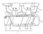
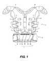
- FIG. 1illustrates a distal plan view of one embodiment of the present invention with a removable elongated coupler shown as the removable connection that couples the protective rib and lower back pads to the protective shoulder pads.
- FIG. 2illustrates a distal plan view of the same embodiment of the present invention as shown in FIG. 1 , in which the removable elongated coupler is removed from one protective rib and lower back pad retaining loop with the protective rib and lower back pad retaining loop remaining inserted in the protective rib and lower back pads retention aperture.
- FIG. 3illustrates a distal plan view of the same embodiment of the present invention as shown in FIG. 1 , in which the removable elongated coupler is removed from one protective rib and lower back pad retaining loop with the protective rib and lower back pad retaining loop evacuated from the protective rib and lower back pads retention aperture.
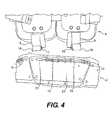
- FIG. 4illustrates a distal plan view of the same embodiment of the present invention as shown in FIG. 1 , in which the removable elongated coupler is removed from both protective rib and lower back pad retaining loops and both protective rib and lower back pad retaining loops are evacuated from the protective rib and lower back pads retention apertures, thus detaching or decoupling the protective rib and lower back pads from the protective shoulder pads.
- FIG. 5illustrates a lateral prospective view of an embodiment of the present invention illustrated in FIG. 1 , in which a loop on the anterior end of the elongated coupler is used to remove the elongated coupler from the straps that couple the protective rib and lower back pads to the protective shoulder pads.
- Embodiments of this inventionrelate generally to protective contact sports pads such as those worn by individuals participating in athletic activities, including contact sports, such as, but not limited to, football, hockey, and lacrosse.
- these embodimentsimprove currently available contact sports pads with a feature that allows emergency medical personnel and/or others to more safely and easily remove the pads in case of suspected neck or cervical spine injury while the individual is in the supine position.
- Typical shoulder pads 4are comprised of anterior (not shown), superior 9 and posterior 11 portions, wherein the anterior portions depend from an anterior face of superior portions 9 , and posterior portions 11 depend from a posterior face of superior portions 9 .
- Superior portions 9comprise a central opening.
- Protective shoulder pads 4protect the chest, shoulders, upper back, and upper arms of the individual wearing shoulder pads 4 .
- the anterior portions of shoulder pads 4protect the individual's chest
- superior portions 9 of protective shoulder pads 4protect the individual's shoulders
- posterior portions 11 of protective shoulder pads 4protect the individual's upper back
- lateral portions (not shown) of protective shoulder pads 4protect the individual's upper arms.
- shoulder pads 4further comprise rib and lower back pads 2 suspended from a portion of shoulder pads 4 , including, but not limited to, posterior portion 11 of shoulder pads 4 .
- Protective rib and lower back pads 2protect the ribs and lower back of the individual wearing protective rib and lower back pads 2 .
- release mechanism 1Actuation of release mechanism 1 permits removal of rib and lower back pads 2 from shoulder pads 4 while the wearer is in the supine position.
- release mechanism 1decouples or detaches protective rib and lower back pads 2 from their corresponding protective shoulder pads 4 while the individual wearing protective shoulder pads 4 is in the supine position, without significantly moving the individual.
- release mechanism 1may comprise strap 5 having a first end and a second end, wherein the first end is in communication with a first pad, and wherein the second end extends from the first pad and comprises retaining loop 14 , retention aperture 21 disposed on a second pad, wherein aperture 21 is sized to fit a width of retaining loop 14 , and elongated coupler 8 sized to fit through orifice 17 disposed in retaining loop 14 .
- the first pad and the second padare mechanically coupled when retaining loop 14 associated with the first pad is passed through retention aperture 21 associated with the second pad and secured in place by threading a second end of elongated coupler 8 through orifice 17 in retaining loop 14 .
- the presence of elongated coupler 8prevents retaining loop 14 from passing back through or egressing from retention aperture 21 .
- Actuating release mechanism 1by grasping and pulling a first end or anterior portion 20 of elongated coupler 8 and removing elongated couple 8 from orifice 17 in retaining loop 14 , permits retaining loop 14 to pass back through or egress from retention aperture 21 , thereby decoupling the first pad from the second pad.
- the first padis shoulder pad 4 and the second pad is rib and lower back pad 2 .
- the first padis rib and lower back pad 2 and the second pad is shoulder pad 4 .
- elongated coupler 8When the first and second pads are in the coupled or attached position, a portion of elongated coupler 8 is disposed on, and may traverse substantially the length of, a posterior portion of the pads, and the first or anterior portion 20 is disposed on an anterior portion of the pads.
- the removal of elongated coupler 8decouples or detaches shoulder pads 4 from rib and lower back pads 2 while the wearer remains in the supine position.
- Elongated coupler 8may be comprised of a cable, cord, belt, pin, strap, tie, filament, wire, tether, or any other suitable structure, or a combination thereof, and may be comprised of metal, plastic, polymer, synthetic, textile, elastic, or any other suitable material, or a combination thereof.
- Elongated coupler 8may possess uniform rigidity or possess portions that vary in rigidity.
- Strap 5may be comprised of a cable, cord, belt, pin, strap, tie, filament, wire, tether, or any other suitable structure, or a combination thereof, and may be comprised of metal, plastic, polymer, synthetic, textile, elastic, or any other suitable material, or a combination thereof.
- There may be a single strap 5or at least two straps. In the case of a single strap 5 , strap 5 is sized to allow rib and lower back pad 2 to suspend from shoulder pad 4 .
- release mechanism 1comprises elongated coupler 8 , two straps 5 , 6 and two apertures 21 , 15 .
- release mechanism 1may comprise left strap 5 and right strap 6 .
- the first end of left strap 5 and the first end of right strap 6are in communication with, attached to, or otherwise disposed on protective shoulder pads 4 .
- Straps 5 , 6may be attached to pads 4 by connectors 3 , 7 , respectively, or the first end of straps 5 , 6 may be molded into pads 4 without the use of connectors 3 , 7 .
- the first end of strap 5is attached to pads 4 by connector 3 and the first end of right strap 6 is attached to the protective shoulder pads 4 with connector 7 .
- Connectors 3 , 7may be any suitable connector, including, but not limited to, rivets, snaps, glue, hook and loop fastener, etc.
- loops 14 , 18are sized such that a portion of loops 14 , 18 having orifices 17 , 19 may pass through retaining apertures 21 , 15 , respectively.
- loops 14 , 18are passed through apertures 21 , 15 by inserting the leading end of loops 14 , 18 through apertures 21 , 15 in a direction initiating from the wearer's side or internal surface of the pads and exiting on the external side of the pads, or the surface facing away from the wearer.
- Left retaining loop 14passes through left retention aperture 21 in protective rib and lower back pads 2 and right retaining loop 18 passes through right retention aperture 15 in protective rib and lower back pads 2 , when rib and lower back pads 2 are in their attached or coupled position to shoulder pads 4 .
- orifice 17 of loop 14is inserted through aperture 21 and orifice 19 of loop 18 is inserted through aperture 15 .
- a second or posterior end of elongated coupler 8is passed or threaded through orifice 17 of retaining loop 14 , then through coupler guidance channel 10 , then through orifice 19 of retaining loop 18 , and the first end of coupler 8 terminates in terminating channel 16 .
- removable elongated coupler 8prevents left retaining loop 14 and right retaining loop 18 from egressing back through retention apertures 21 and 15 , respectively, in the body of the protective rib and lower back pads 2 .
- removable coupler 8is guided along its desired path via guidance channel 10 to facilitate ease of removal.
- guidance channel 10 and terminating channel 16attach to protective rib and lower back pads 2 with channel attaching ties 12 .
- guidance channel 10can be manufactured into protective rib and lower back pads 2 forming guidance channel 10 , or any suitable retainer or eyelet may be molded into or attached to pads 2 to serve as guidance channel 10 .
- loops 14 , 18are received by apertures 21 , 15 , wherein loops 14 , 18 pass through or are threaded through the apertures 21 , 15 .
- Loops 14 , 18are retained in their position through or in the apertures 21 , 15 by the insertion of removable elongated coupler 8 through the loop 14 , 18 received by and passing through apertures 21 , 15 , thereby assembling the shoulder pads 4 and the rib and lower back pads 2 .
- Actuation or removal of elongated coupler 8 from loops 14 , 18permits egress of loops 14 , 18 back through or from apertures 21 , 15 and permits decoupling or disassembly of shoulder pads 4 and rib and lower back pads 2 while the wearer remains in the supine position.
- Elongated coupler 8is routed from posterior portion 23 of the rib and lower pads 2 and the first or anterior portion 20 terminates on or near anterior portion 24 of rib and lower back pads 2 .
- elongated coupler 8is removed through retaining loops 14 , 18 , guidance channel 10 , and terminating channel 16 by pulling anterior portion 20 of elongated coupler 8 , effectively releasing elongated coupler 8 from retaining loops 14 , 18 , guidance channel 10 , and terminating channel 16 .
- Retaining loops 14 , 18are now capable of passing back or egressing through apertures 21 , 15 , decoupling pads 2 from pads 4 .
- Anterior portion 20 of elongated coupler 8is accessed from the anterior portion 24 of pads 2 while the wearer is in the supine position, thereby minimizing movement of the individual.
- removable elongated coupler 8is partially removed from protective rib and lower back pads 2 by grasping and pulling anterior end 20 of elongated coupler 8 that is disposed on anterior portion 24 of pad 2 .
- elongated coupler 8is removed from terminating channel 16 and orifice 19 of right retaining loop 18 .
- Right retaining loop 18is released and may pass back through or egress through right retention aperture 15 in protective rib and lower back pads 2 , thus decoupling or disconnecting the right portion of protective shoulder pads 4 from protective rib and lower back pads 2 .
- FIG. 3illustrates right retaining loop 18 removed from right retention aperture 15 in protective rib and lower back pads 2 and the right portion of protective shoulder pads 4 decoupled or disconnected from protective rib and lower back pads 2 , with removable elongated coupler 8 in the same position as in FIG. 2 .
- Removable elongated coupler 8was routed through orifice 19 in right retaining loop 18 .
- elongated coupler 8is further removed from protective rib and lower back pads 2 .
- the second or posterior portion of elongated coupler 8is removed from terminating channel 16 , orifice 19 of right retaining loop 18 , cable guidance channel 10 , and orifice 14 of left retaining loop 14 .
- Left retaining loop 14is released and may now egress or pass back through left retention aperture 21 in protective rib and lower back pads 2
- right retaining loop 18is released and may now pass through right retention aperture 15 in protective rib and lower back pads 2 .
- Removable elongated coupler 8was routed through orifice 19 in right retaining loop 18 and through orifice 17 in left retaining loop 14 . In this state, protective rib and lower back pads 2 may be completely disconnected or decoupled from protective shoulder pads 4 .
- Protective shoulder pads 4 and protective rib and lower back pads 2may be recoupled for future use by passing left terminating loop 14 through the left retention aperture 21 in protective rib and lower back pads 2 and right retaining loop 18 through right retention aperture 15 in protective rib and lower back pads 2 followed by passing or threading removable elongated coupler 8 through orifice 17 in left retaining loop 14 , through cable guidance channel 10 , through orifice 19 in right retaining loop 18 and finally into terminating channel 16 .
- loops 18 , 14may be constructed of a pliable material that is cable of passing through retention apertures 15 , 21 while the individual wearing protective rib and lower back pads 2 is in the supine position.
- retaining loops 18 , 14are riveted to straps 6 , 5 .
- Retaining loops 18 , 14could optionally be manufactured into straps 6 , 5 as one piece or connected by any other suitable means, including, but not limited to rivets, snaps, hook and loop fastener, glue, etc.
- retaining loops 18 , 14may be composed of Nylon, but any other pliable material capable of restraining retaining loops 18 , 14 is acceptable.
- Another feature of straps 6 , 5is the material that the strap other than retaining loops 18 , 14 may be composed of. It is generally desirable to produce straps 6 , 5 from a material that will not absorb moisture such as water or perspiration. Straps 6 , 5 of this embodiment of protective rib and lower back pads 2 are composed of nonabsorbent plastic; however, other material may be utilized, whether the material is nonabsorbent or not.
- FIG. 5illustrates a gripping structure, for example, a loop, disposed on the first or anterior end 20 of elongated coupler 8 .
- This gripping structuremay be used to assist in the removal of elongated coupler 8 from cable guidance channel 10 , retaining loops 18 , 14 , and terminating channel 16 of protective rib and lower back pads 2 .
- the gripping structuremay be retained in place on anterior portion 24 of pads 2 by a retention mechanism 22 .
- Retention mechanism 22may be composed of a hook and loop fastener or other suitable type of fastener.
- Anterior end 20 of elongated coupler 8is accessible from anterior portion 24 of the shoulder and/or rib pads to allow extraction of elongated coupler 8 while the wearer is in the supine position.
- the release mechanismmay comprise one strap with one loop, one orifice, and one aperture.
- the first end of the strapmay be connected to the shoulder pad and the aperture disposed on the rib/back pad, or in an alternative embodiment, the first end of the strap may be connected to the rib/back pad and the aperture disposed on the shoulder pad.
Landscapes
- Health & Medical Sciences (AREA)
- General Health & Medical Sciences (AREA)
- Physical Education & Sports Medicine (AREA)
- Engineering & Computer Science (AREA)
- Textile Engineering (AREA)
- Otolaryngology (AREA)
- Heart & Thoracic Surgery (AREA)
- Orthopedic Medicine & Surgery (AREA)
- Orthopedics, Nursing, And Contraception (AREA)
- Professional, Industrial, Or Sporting Protective Garments (AREA)
Abstract
Description
Claims (20)
Priority Applications (1)
| Application Number | Priority Date | Filing Date | Title |
|---|---|---|---|
| US13/867,810US8850613B2 (en) | 2009-01-06 | 2013-04-22 | Protective contact sports pads with release mechanism |
Applications Claiming Priority (3)
| Application Number | Priority Date | Filing Date | Title |
|---|---|---|---|
| US12/319,429US7962968B2 (en) | 2009-01-06 | 2009-01-06 | Protective rib and lower back pads with release mechanisms |
| US12/821,989US8424112B2 (en) | 2009-01-06 | 2010-06-23 | Protective rib and lower back pads with release mechanism |
| US13/867,810US8850613B2 (en) | 2009-01-06 | 2013-04-22 | Protective contact sports pads with release mechanism |
Related Parent Applications (1)
| Application Number | Title | Priority Date | Filing Date |
|---|---|---|---|
| US12/821,989ContinuationUS8424112B2 (en) | 2009-01-06 | 2010-06-23 | Protective rib and lower back pads with release mechanism |
Publications (2)
| Publication Number | Publication Date |
|---|---|
| US20130227769A1 US20130227769A1 (en) | 2013-09-05 |
| US8850613B2true US8850613B2 (en) | 2014-10-07 |
Family
ID=43061413
Family Applications (2)
| Application Number | Title | Priority Date | Filing Date |
|---|---|---|---|
| US12/821,989Expired - Fee RelatedUS8424112B2 (en) | 2009-01-06 | 2010-06-23 | Protective rib and lower back pads with release mechanism |
| US13/867,810ActiveUS8850613B2 (en) | 2009-01-06 | 2013-04-22 | Protective contact sports pads with release mechanism |
Family Applications Before (1)
| Application Number | Title | Priority Date | Filing Date |
|---|---|---|---|
| US12/821,989Expired - Fee RelatedUS8424112B2 (en) | 2009-01-06 | 2010-06-23 | Protective rib and lower back pads with release mechanism |
Country Status (1)
| Country | Link |
|---|---|
| US (2) | US8424112B2 (en) |
Cited By (4)
| Publication number | Priority date | Publication date | Assignee | Title |
|---|---|---|---|---|
| US20140075650A1 (en)* | 2012-09-16 | 2014-03-20 | Adam Garrison | Tactical gun belt system |
| US10646769B1 (en) | 2016-04-07 | 2020-05-12 | Nike, Inc. | Discrete shoulder sleeve for a shoulder-pad system |
| US11000755B2 (en) | 2016-04-07 | 2021-05-11 | Nike, Inc. | Impact-attenuation sub-layer for a shoulder-pad system |
| US11052301B2 (en) | 2016-04-07 | 2021-07-06 | Nike, Inc. | Securing garment for a shoulder-pad system |
Families Citing this family (8)
| Publication number | Priority date | Publication date | Assignee | Title |
|---|---|---|---|---|
| US8424112B2 (en)* | 2009-01-06 | 2013-04-23 | Riddell, Inc. | Protective rib and lower back pads with release mechanism |
| AU2010266440B2 (en)* | 2009-06-30 | 2013-11-07 | Lineweight Llc | Personal load distribution device |
| EP2591305A1 (en)* | 2010-07-09 | 2013-05-15 | BAE Systems Speciality Defense Systems of Pennsylvania, Inc. | Modular and scalable soldier's garment |
| US20130291294A1 (en)* | 2010-11-18 | 2013-11-07 | Manny Legace | Chest protector with movable abdomen protector |
| US9271559B2 (en)* | 2011-08-29 | 2016-03-01 | Mystery Ranch Limited | Body armor support harness |
| CN104955347A (en)* | 2012-11-06 | 2015-09-30 | Gk专业公司 | Protective body armor having a front opening |
| US20140173816A1 (en)* | 2012-12-21 | 2014-06-26 | Claude Grady | Support Waistband With Bodily Protective Elements |
| US10292439B2 (en)* | 2014-01-31 | 2019-05-21 | Bauer Hockey, Llc | Stretchable strap having a padding element |
Citations (46)
| Publication number | Priority date | Publication date | Assignee | Title |
|---|---|---|---|---|
| US1298618A (en) | 1918-12-06 | 1919-03-25 | Frank Wloszek | Soldier's armor. |
| US2477989A (en) | 1946-08-29 | 1949-08-02 | Maida Thomas La | Safety jacket |
| US3431560A (en) | 1967-03-16 | 1969-03-11 | Russell A Austin | Shoulder guard for football players |
| US3514784A (en) | 1969-02-07 | 1970-06-02 | Robert F Mcdavid | Protective football apparatus |
| US3740762A (en) | 1971-04-22 | 1973-06-26 | Protective Pads Inc | Pad interlocking apparatus |
| US3740763A (en) | 1971-12-22 | 1973-06-26 | Ato Inc | Football shoulder pad |
| US4295227A (en) | 1980-04-25 | 1981-10-20 | A-T-O Inc. | Shoulder pad |
| US4317237A (en)* | 1979-09-20 | 1982-03-02 | Hughie Big Canoe | Chest protector |
| US4322859A (en) | 1980-04-25 | 1982-04-06 | A-T-O Inc. | Shoulder pad |
| US4441211A (en) | 1983-03-25 | 1984-04-10 | Houston Protective Equipment, Inc. | Protective batting jacket |
| US4467475A (en) | 1983-05-11 | 1984-08-28 | Gregory John R | Upper body protector apparatus |
| US4486901A (en) | 1982-03-12 | 1984-12-11 | Houston Protective Equipment, Inc. | Multi-layered, open-celled foam shock absorbing structure for athletic equipment |
| US4513449A (en) | 1983-03-25 | 1985-04-30 | Donzis Byron A | Shock absorbing athletic equipment |
| US4590622A (en)* | 1985-07-18 | 1986-05-27 | All American Inc. | Shoulder, chest and neck protecting device |
| US4694505A (en)* | 1984-03-30 | 1987-09-22 | Corrado Flosi | Upper body protector for off-road riders |
| US4872216A (en) | 1988-05-13 | 1989-10-10 | Riddell, Inc. | Cantilever strap for football shoulder pads |
| US4874640A (en) | 1987-09-21 | 1989-10-17 | Donzis Byron A | Impact absorbing composites and their production |
| US4926503A (en) | 1988-05-13 | 1990-05-22 | Riddell, Inc. | Athletic shock absorbing pad |
| US4985931A (en) | 1989-10-17 | 1991-01-22 | Riddell, Inc. | Shock absorbing pad structure for athletic equipment |
| US5029341A (en)* | 1989-08-22 | 1991-07-09 | Riddell, Inc. | Football shoulder pad |
| US5035009A (en) | 1990-09-27 | 1991-07-30 | Riddell, Inc. | Protective helmet and liner |
| US5107542A (en) | 1991-03-21 | 1992-04-28 | Zide Robert M | Front-lock stabilizer for protective shoulder pads |
| USD328159S (en) | 1989-06-06 | 1992-07-21 | Donzis Laboratories, Inc. | Body pad |
| US5159715A (en) | 1991-05-28 | 1992-11-03 | Ampac Enterprises, Inc. | Shoulder pad with readily removable padding |
| US5204993A (en)* | 1989-10-25 | 1993-04-27 | Victor Siemens | Goalie chest pad |
| US5235715A (en) | 1987-09-21 | 1993-08-17 | Donzis Byron A | Impact asborbing composites and their production |
| US5337417A (en)* | 1993-08-25 | 1994-08-16 | Figgie International Inc. | Rib protector |
| US5404590A (en) | 1993-10-01 | 1995-04-11 | Riddell, Inc. | Football helmet motion restrictor |
| US5530966A (en)* | 1992-12-21 | 1996-07-02 | West; Joseph H. | Protective garment for baseball umpires having an inner cushioned layer and an outer layer of interconnected plates |
| US5794275A (en) | 1996-02-09 | 1998-08-18 | Donzis; Byron A. | Impact absorbing shield for protective gear |
| US5881395A (en) | 1993-07-08 | 1999-03-16 | Donzis; Byron A | Impact absorbing pad |
| US5987654A (en)* | 1997-11-19 | 1999-11-23 | Bauer, Inc. | Light-weight shoulder pads |
| US6175967B1 (en) | 1996-02-02 | 2001-01-23 | Byron A. Donzis | Air fit protective system |
| US6425195B1 (en) | 1987-09-21 | 2002-07-30 | Byron A. Donzis | Impact absorbing composites and their production |
| US6769137B2 (en) | 2001-10-24 | 2004-08-03 | D'annunzio Timothy B. | Cutaway vests |
| US20060010590A1 (en) | 2004-07-14 | 2006-01-19 | Atlas Sprots And Athletic Products | Shoulder protection system |
| US7020897B2 (en) | 2003-07-08 | 2006-04-04 | Eagle Industries Unlimited, Inc. | Cut away vest |
| US7047570B2 (en) | 2003-07-08 | 2006-05-23 | Eagle Industries Unlimited, Inc. | Cut away vest |
| WO2008108856A2 (en) | 2006-05-30 | 2008-09-12 | The Board Of Regents For Oklahoma State University | Antiballistic garment |
| US7424748B1 (en) | 2006-06-06 | 2008-09-16 | Eagle Industries Unlimited, Inc. | Quick release system for armor plates in a ballistic resistant vest and method |
| US20080263737A1 (en) | 2007-04-27 | 2008-10-30 | Parks Ardith D | Emergency release cable system |
| US7506384B2 (en) | 2004-09-13 | 2009-03-24 | Riddell, Inc. | Shoulder pad for contact sports |
| WO2009051619A2 (en) | 2007-06-26 | 2009-04-23 | Mcbride William B | Rapid doffing vest |
| US7962968B2 (en)* | 2009-01-06 | 2011-06-21 | Michael E Kordecki | Protective rib and lower back pads with release mechanisms |
| US8214929B2 (en) | 2004-09-13 | 2012-07-10 | Riddell, Inc. | Shoulder pads |
| US8424112B2 (en)* | 2009-01-06 | 2013-04-23 | Riddell, Inc. | Protective rib and lower back pads with release mechanism |
- 2010
- 2010-06-23USUS12/821,989patent/US8424112B2/ennot_activeExpired - Fee Related
- 2013
- 2013-04-22USUS13/867,810patent/US8850613B2/enactiveActive
Patent Citations (49)
| Publication number | Priority date | Publication date | Assignee | Title |
|---|---|---|---|---|
| US1298618A (en) | 1918-12-06 | 1919-03-25 | Frank Wloszek | Soldier's armor. |
| US2477989A (en) | 1946-08-29 | 1949-08-02 | Maida Thomas La | Safety jacket |
| US3431560A (en) | 1967-03-16 | 1969-03-11 | Russell A Austin | Shoulder guard for football players |
| US3514784A (en) | 1969-02-07 | 1970-06-02 | Robert F Mcdavid | Protective football apparatus |
| US3740762A (en) | 1971-04-22 | 1973-06-26 | Protective Pads Inc | Pad interlocking apparatus |
| US3740763A (en) | 1971-12-22 | 1973-06-26 | Ato Inc | Football shoulder pad |
| US4317237A (en)* | 1979-09-20 | 1982-03-02 | Hughie Big Canoe | Chest protector |
| US4295227A (en) | 1980-04-25 | 1981-10-20 | A-T-O Inc. | Shoulder pad |
| US4322859A (en) | 1980-04-25 | 1982-04-06 | A-T-O Inc. | Shoulder pad |
| US4486901A (en) | 1982-03-12 | 1984-12-11 | Houston Protective Equipment, Inc. | Multi-layered, open-celled foam shock absorbing structure for athletic equipment |
| US4513449A (en) | 1983-03-25 | 1985-04-30 | Donzis Byron A | Shock absorbing athletic equipment |
| US4441211A (en) | 1983-03-25 | 1984-04-10 | Houston Protective Equipment, Inc. | Protective batting jacket |
| US4467475A (en) | 1983-05-11 | 1984-08-28 | Gregory John R | Upper body protector apparatus |
| US4694505A (en)* | 1984-03-30 | 1987-09-22 | Corrado Flosi | Upper body protector for off-road riders |
| US4590622A (en)* | 1985-07-18 | 1986-05-27 | All American Inc. | Shoulder, chest and neck protecting device |
| US4874640A (en) | 1987-09-21 | 1989-10-17 | Donzis Byron A | Impact absorbing composites and their production |
| US6425195B1 (en) | 1987-09-21 | 2002-07-30 | Byron A. Donzis | Impact absorbing composites and their production |
| US5235715A (en) | 1987-09-21 | 1993-08-17 | Donzis Byron A | Impact asborbing composites and their production |
| US4872216A (en) | 1988-05-13 | 1989-10-10 | Riddell, Inc. | Cantilever strap for football shoulder pads |
| US4926503A (en) | 1988-05-13 | 1990-05-22 | Riddell, Inc. | Athletic shock absorbing pad |
| USD328159S (en) | 1989-06-06 | 1992-07-21 | Donzis Laboratories, Inc. | Body pad |
| US5029341A (en)* | 1989-08-22 | 1991-07-09 | Riddell, Inc. | Football shoulder pad |
| US4985931A (en) | 1989-10-17 | 1991-01-22 | Riddell, Inc. | Shock absorbing pad structure for athletic equipment |
| US5204993A (en)* | 1989-10-25 | 1993-04-27 | Victor Siemens | Goalie chest pad |
| US5035009A (en) | 1990-09-27 | 1991-07-30 | Riddell, Inc. | Protective helmet and liner |
| US5107542A (en) | 1991-03-21 | 1992-04-28 | Zide Robert M | Front-lock stabilizer for protective shoulder pads |
| US5159715A (en) | 1991-05-28 | 1992-11-03 | Ampac Enterprises, Inc. | Shoulder pad with readily removable padding |
| US5530966A (en)* | 1992-12-21 | 1996-07-02 | West; Joseph H. | Protective garment for baseball umpires having an inner cushioned layer and an outer layer of interconnected plates |
| US5881395A (en) | 1993-07-08 | 1999-03-16 | Donzis; Byron A | Impact absorbing pad |
| US5337417A (en)* | 1993-08-25 | 1994-08-16 | Figgie International Inc. | Rib protector |
| US5404590A (en) | 1993-10-01 | 1995-04-11 | Riddell, Inc. | Football helmet motion restrictor |
| US6175967B1 (en) | 1996-02-02 | 2001-01-23 | Byron A. Donzis | Air fit protective system |
| US5794275A (en) | 1996-02-09 | 1998-08-18 | Donzis; Byron A. | Impact absorbing shield for protective gear |
| US5987654A (en)* | 1997-11-19 | 1999-11-23 | Bauer, Inc. | Light-weight shoulder pads |
| US6769137B2 (en) | 2001-10-24 | 2004-08-03 | D'annunzio Timothy B. | Cutaway vests |
| US6948188B2 (en)* | 2001-10-24 | 2005-09-27 | Paraclete Armor & Equipment, Inc. | Cutaway vests |
| US7243376B2 (en) | 2003-07-08 | 2007-07-17 | Eagle Industries Unlimited, Inc. | Cut away vest |
| US7020897B2 (en) | 2003-07-08 | 2006-04-04 | Eagle Industries Unlimited, Inc. | Cut away vest |
| US7047570B2 (en) | 2003-07-08 | 2006-05-23 | Eagle Industries Unlimited, Inc. | Cut away vest |
| US20060010590A1 (en) | 2004-07-14 | 2006-01-19 | Atlas Sprots And Athletic Products | Shoulder protection system |
| US7506384B2 (en) | 2004-09-13 | 2009-03-24 | Riddell, Inc. | Shoulder pad for contact sports |
| US7930773B2 (en) | 2004-09-13 | 2011-04-26 | Riddell, Inc. | Shoulder pad for contact sports |
| US8214929B2 (en) | 2004-09-13 | 2012-07-10 | Riddell, Inc. | Shoulder pads |
| WO2008108856A2 (en) | 2006-05-30 | 2008-09-12 | The Board Of Regents For Oklahoma State University | Antiballistic garment |
| US7424748B1 (en) | 2006-06-06 | 2008-09-16 | Eagle Industries Unlimited, Inc. | Quick release system for armor plates in a ballistic resistant vest and method |
| US20080263737A1 (en) | 2007-04-27 | 2008-10-30 | Parks Ardith D | Emergency release cable system |
| WO2009051619A2 (en) | 2007-06-26 | 2009-04-23 | Mcbride William B | Rapid doffing vest |
| US7962968B2 (en)* | 2009-01-06 | 2011-06-21 | Michael E Kordecki | Protective rib and lower back pads with release mechanisms |
| US8424112B2 (en)* | 2009-01-06 | 2013-04-23 | Riddell, Inc. | Protective rib and lower back pads with release mechanism |
Cited By (4)
| Publication number | Priority date | Publication date | Assignee | Title |
|---|---|---|---|---|
| US20140075650A1 (en)* | 2012-09-16 | 2014-03-20 | Adam Garrison | Tactical gun belt system |
| US10646769B1 (en) | 2016-04-07 | 2020-05-12 | Nike, Inc. | Discrete shoulder sleeve for a shoulder-pad system |
| US11000755B2 (en) | 2016-04-07 | 2021-05-11 | Nike, Inc. | Impact-attenuation sub-layer for a shoulder-pad system |
| US11052301B2 (en) | 2016-04-07 | 2021-07-06 | Nike, Inc. | Securing garment for a shoulder-pad system |
Also Published As
| Publication number | Publication date |
|---|---|
| US8424112B2 (en) | 2013-04-23 |
| US20100281607A1 (en) | 2010-11-11 |
| US20130227769A1 (en) | 2013-09-05 |
Similar Documents
| Publication | Publication Date | Title |
|---|---|---|
| US8850613B2 (en) | Protective contact sports pads with release mechanism | |
| US10220291B2 (en) | Protective shoulder pads with release mechanism | |
| WO2010080825A1 (en) | Protective rib and lower back pads with release mechanism | |
| US8918918B2 (en) | Apparatus for preventing neck injury, spinal cord injury and concussion | |
| US8087102B2 (en) | Protective shoulder pads with release mechanisms | |
| US5015865A (en) | X-ray-protective surgical garment having a removable lead insert | |
| KR101883055B1 (en) | A cervical collar | |
| US10682558B2 (en) | Training apparatus, system and method for contact sports | |
| EP3229628B1 (en) | An airway opening device for helmets and a helmet comprising the same | |
| US8443468B2 (en) | Cervical spine protection collar for contact and non-contact activities | |
| EP1680055B1 (en) | Cervical collar | |
| US20150190694A1 (en) | Football accessory for downing the ball carrier | |
| US20180036161A1 (en) | Joint stabilizing orthopedic device | |
| Sanchez et al. | Field-side and prehospital management of the spine-injured athlete | |
| CA2822642A1 (en) | Apparatus for preventing neck injury, spinal cord injury and concussion | |
| CN112641554A (en) | Novel bound clothes | |
| Patel et al. | Emergency removal of football helmets | |
| CN216724924U (en) | Medical restraint gloves | |
| CN210990995U (en) | A bone distraction protection device | |
| CN219553250U (en) | Flexible radiation protection device | |
| US10814198B2 (en) | System for downing a ball carrier and for tackle training | |
| CN211187589U (en) | Medical wrist strap for rope weaving | |
| CN114569366B (en) | A protective device for medical personnel for cardiopulmonary resuscitation emergency transfer | |
| Mastrangelo | Eye and face injuries in high school hockey: cutting down the risks | |
| CN209661816U (en) | A kind of neck puncturing operation accessory |
Legal Events
| Date | Code | Title | Description |
|---|---|---|---|
| AS | Assignment | Owner name:MORGAN STANLEY SENIOR FUNDING, INC., AS AGENT, NEW YORK Free format text:SECURITY INTEREST;ASSIGNORS:BRG SPORTS, INC.;RIDDELL SPORTS GROUP, INC.;RIDDELL, INC.;AND OTHERS;REEL/FRAME:032694/0260 Effective date:20140415 Owner name:MORGAN STANLEY SENIOR FUNDING, INC., AS AGENT, NEW YORK Free format text:SECURITY INTEREST;ASSIGNORS:BRG SPORTS, INC.;RIDDELL SPORTS GROUP, INC.;RIDDELL, INC.;AND OTHERS;REEL/FRAME:032694/0227 Effective date:20140415 Owner name:MORGAN STANLEY SENIOR FUNDING, INC., AS AGENT, NEW YORK Free format text:SECURITY INTEREST;ASSIGNORS:BRG SPORTS, INC.;RIDDELL SPORTS GROUP, INC.;RIDDELL, INC.;AND OTHERS;REEL/FRAME:032694/0196 Effective date:20140415 Owner name:MORGAN STANLEY SENIOR FUNDING, INC., AS AGENT, NEW Free format text:SECURITY INTEREST;ASSIGNORS:BRG SPORTS, INC.;RIDDELL SPORTS GROUP, INC.;RIDDELL, INC.;AND OTHERS;REEL/FRAME:032694/0260 Effective date:20140415 Owner name:MORGAN STANLEY SENIOR FUNDING, INC., AS AGENT, NEW Free format text:SECURITY INTEREST;ASSIGNORS:BRG SPORTS, INC.;RIDDELL SPORTS GROUP, INC.;RIDDELL, INC.;AND OTHERS;REEL/FRAME:032694/0196 Effective date:20140415 Owner name:MORGAN STANLEY SENIOR FUNDING, INC., AS AGENT, NEW Free format text:SECURITY INTEREST;ASSIGNORS:BRG SPORTS, INC.;RIDDELL SPORTS GROUP, INC.;RIDDELL, INC.;AND OTHERS;REEL/FRAME:032694/0227 Effective date:20140415 | |
| STCF | Information on status: patent grant | Free format text:PATENTED CASE | |
| AS | Assignment | Owner name:RIDMARK CORPORATION, OHIO Free format text:RELEASE BY SECURED PARTY;ASSIGNOR:MORGAN STANLEY SENIOR FUNDING, INC.;REEL/FRAME:038329/0477 Effective date:20160401 Owner name:RIDMARK CORPORATION, OHIO Free format text:RELEASE BY SECURED PARTY;ASSIGNOR:MORGAN STANLEY SENIOR FUNDING, INC.;REEL/FRAME:038329/0167 Effective date:20160401 Owner name:BRG SPORTS, INC., CALIFORNIA Free format text:RELEASE BY SECURED PARTY;ASSIGNOR:MORGAN STANLEY SENIOR FUNDING, INC.;REEL/FRAME:038329/0477 Effective date:20160401 Owner name:RIDDELL, INC., ILLINOIS Free format text:RELEASE BY SECURED PARTY;ASSIGNOR:MORGAN STANLEY SENIOR FUNDING, INC.;REEL/FRAME:038329/0477 Effective date:20160401 Owner name:ALL AMERICAN SPORTS CORPORATION, OHIO Free format text:RELEASE BY SECURED PARTY;ASSIGNOR:MORGAN STANLEY SENIOR FUNDING, INC.;REEL/FRAME:038329/0477 Effective date:20160401 Owner name:ALL AMERICAN SPORTS CORPORATION, OHIO Free format text:RELEASE BY SECURED PARTY;ASSIGNOR:MORGAN STANLEY SENIOR FUNDING, INC.;REEL/FRAME:038329/0167 Effective date:20160401 Owner name:BELL SPORTS, INC., TEXAS Free format text:RELEASE BY SECURED PARTY;ASSIGNOR:MORGAN STANLEY SENIOR FUNDING, INC.;REEL/FRAME:038329/0167 Effective date:20160401 Owner name:MACMARK CORPORATION, OHIO Free format text:RELEASE BY SECURED PARTY;ASSIGNOR:MORGAN STANLEY SENIOR FUNDING, INC.;REEL/FRAME:038329/0477 Effective date:20160401 Owner name:EQUILINK LICENSING, LLC, OHIO Free format text:RELEASE BY SECURED PARTY;ASSIGNOR:MORGAN STANLEY SENIOR FUNDING, INC.;REEL/FRAME:038329/0477 Effective date:20160401 Owner name:MACMARK CORPORATION, OHIO Free format text:RELEASE BY SECURED PARTY;ASSIGNOR:MORGAN STANLEY SENIOR FUNDING, INC.;REEL/FRAME:038328/0965 Effective date:20160401 Owner name:EQUILINK LICENSING, LLC, OHIO Free format text:RELEASE BY SECURED PARTY;ASSIGNOR:MORGAN STANLEY SENIOR FUNDING, INC.;REEL/FRAME:038329/0167 Effective date:20160401 Owner name:EQUILINK LICENSING, LLC, OHIO Free format text:RELEASE BY SECURED PARTY;ASSIGNOR:MORGAN STANLEY SENIOR FUNDING, INC.;REEL/FRAME:038328/0965 Effective date:20160401 Owner name:MACMARK CORPORATION, OHIO Free format text:RELEASE BY SECURED PARTY;ASSIGNOR:MORGAN STANLEY SENIOR FUNDING, INC.;REEL/FRAME:038329/0167 Effective date:20160401 Owner name:RIDDELL SPORTS GROUP, INC., ILLINOIS Free format text:RELEASE BY SECURED PARTY;ASSIGNOR:MORGAN STANLEY SENIOR FUNDING, INC.;REEL/FRAME:038329/0477 Effective date:20160401 Owner name:RIDDELL, INC., ILLINOIS Free format text:RELEASE BY SECURED PARTY;ASSIGNOR:MORGAN STANLEY SENIOR FUNDING, INC.;REEL/FRAME:038328/0965 Effective date:20160401 Owner name:RIDDELL SPORTS GROUP, INC., ILLINOIS Free format text:RELEASE BY SECURED PARTY;ASSIGNOR:MORGAN STANLEY SENIOR FUNDING, INC.;REEL/FRAME:038328/0965 Effective date:20160401 Owner name:ALL AMERICAN SPORTS CORPORTION, OHIO Free format text:RELEASE BY SECURED PARTY;ASSIGNOR:MORGAN STANLEY SENIOR FUNDING, INC.;REEL/FRAME:038328/0965 Effective date:20160401 Owner name:BRG SPORTS, INC., CALIFORNIA Free format text:RELEASE BY SECURED PARTY;ASSIGNOR:MORGAN STANLEY SENIOR FUNDING, INC.;REEL/FRAME:038328/0965 Effective date:20160401 Owner name:BRG SPORTS, INC., CALIFORNIA Free format text:RELEASE BY SECURED PARTY;ASSIGNOR:MORGAN STANLEY SENIOR FUNDING, INC.;REEL/FRAME:038329/0167 Effective date:20160401 Owner name:RIDDELL SPORTS GROUP, INC., ILLINOIS Free format text:RELEASE BY SECURED PARTY;ASSIGNOR:MORGAN STANLEY SENIOR FUNDING, INC.;REEL/FRAME:038329/0167 Effective date:20160401 Owner name:BELL SPORTS, INC., TEXAS Free format text:RELEASE BY SECURED PARTY;ASSIGNOR:MORGAN STANLEY SENIOR FUNDING, INC.;REEL/FRAME:038328/0965 Effective date:20160401 Owner name:RIDELL, INC., ILLINOIS Free format text:RELEASE BY SECURED PARTY;ASSIGNOR:MORGAN STANLEY SENIOR FUNDING, INC.;REEL/FRAME:038329/0167 Effective date:20160401 Owner name:BELL SPORTS, INC., TEXAS Free format text:RELEASE BY SECURED PARTY;ASSIGNOR:MORGAN STANLEY SENIOR FUNDING, INC.;REEL/FRAME:038329/0477 Effective date:20160401 Owner name:RIDMARK CORPORATION, OHIO Free format text:RELEASE BY SECURED PARTY;ASSIGNOR:MORGAN STANLEY SENIOR FUNDING, INC.;REEL/FRAME:038328/0965 Effective date:20160401 | |
| AS | Assignment | Owner name:BMO HARRIS BANK N.A., AS ADMINISTRATIVE AGENT, ILLINOIS Free format text:GRANT OF A SECURITY INTEREST - PATENTS;ASSIGNORS:RIDDELL, INC.;RIDDELL SPORTS GROUP, INC.;REEL/FRAME:038827/0259 Effective date:20160526 Owner name:BMO HARRIS BANK N.A., AS ADMINISTRATIVE AGENT, ILL Free format text:GRANT OF A SECURITY INTEREST - PATENTS;ASSIGNORS:RIDDELL, INC.;RIDDELL SPORTS GROUP, INC.;REEL/FRAME:038827/0259 Effective date:20160526 | |
| MAFP | Maintenance fee payment | Free format text:PAYMENT OF MAINTENANCE FEE, 4TH YEAR, LARGE ENTITY (ORIGINAL EVENT CODE: M1551) Year of fee payment:4 | |
| AS | Assignment | Owner name:BMO HARRIS BANK N.A., AS ADMINISTRATIVE AGENT, ILLINOIS Free format text:SECURITY INTEREST;ASSIGNOR:RIDDELL, INC.;REEL/FRAME:046392/0343 Effective date:20180615 Owner name:BMO HARRIS BANK N.A., AS ADMINISTRATIVE AGENT, ILL Free format text:SECURITY INTEREST;ASSIGNOR:RIDDELL, INC.;REEL/FRAME:046392/0343 Effective date:20180615 | |
| AS | Assignment | Owner name:RIDDELL, INC., OHIO Free format text:RELEASE BY SECURED PARTY;ASSIGNOR:BMO HARRIS BANK N.A., AS ADMINISTRATIVE AGENT;REEL/FRAME:047525/0325 Effective date:20180615 Owner name:RIDDELL SPORTS GROUP, INC., ILLINOIS Free format text:RELEASE BY SECURED PARTY;ASSIGNOR:BMO HARRIS BANK N.A., AS ADMINISTRATIVE AGENT;REEL/FRAME:047525/0325 Effective date:20180615 | |
| AS | Assignment | Owner name:RIDDELL, INC., ILLINOIS Free format text:ASSIGNMENT OF ASSIGNORS INTEREST;ASSIGNOR:KORDECKI, MICHAEL E.;REEL/FRAME:053540/0541 Effective date:20200819 | |
| AS | Assignment | Owner name:BMO HARRIS BANK N.A. AS ADMINISTRATIVE AGENT, ILLINOIS Free format text:SECURITY INTEREST;ASSIGNOR:RIDDELL, INC.;REEL/FRAME:056458/0664 Effective date:20210128 | |
| AS | Assignment | Owner name:PNC BANK, NATIONAL ASSOCIATION, AS AGENT, PENNSYLVANIA Free format text:SECURITY INTEREST;ASSIGNOR:RIDDELL, INC.;REEL/FRAME:057390/0052 Effective date:20210831 | |
| AS | Assignment | Owner name:RIDDELL, INC., OHIO Free format text:RELEASE BY SECURED PARTY;ASSIGNOR:BMO HARRIS BANK N.A.;REEL/FRAME:057650/0635 Effective date:20210831 | |
| MAFP | Maintenance fee payment | Free format text:PAYMENT OF MAINTENANCE FEE, 8TH YEAR, LARGE ENTITY (ORIGINAL EVENT CODE: M1552); ENTITY STATUS OF PATENT OWNER: LARGE ENTITY Year of fee payment:8 |