US8849402B2 - System and method for contactless power transfer in implantable devices - Google Patents
System and method for contactless power transfer in implantable devicesDownload PDFInfo
- Publication number
- US8849402B2 US8849402B2US13/052,196US201113052196AUS8849402B2US 8849402 B2US8849402 B2US 8849402B2US 201113052196 AUS201113052196 AUS 201113052196AUS 8849402 B2US8849402 B2US 8849402B2
- Authority
- US
- United States
- Prior art keywords
- coil
- power
- magnetic field
- rechargeable battery
- implantable device
- Prior art date
- Legal status (The legal status is an assumption and is not a legal conclusion. Google has not performed a legal analysis and makes no representation as to the accuracy of the status listed.)
- Active, expires
Links
- 238000012546transferMethods0.000titleclaimsabstractdescription45
- 238000000034methodMethods0.000titleclaimsabstractdescription21
- 230000008878couplingEffects0.000claimsabstractdescription9
- 238000010168coupling processMethods0.000claimsabstractdescription9
- 238000005859coupling reactionMethods0.000claimsabstractdescription9
- 230000000747cardiac effectEffects0.000claimsdescription2
- 230000005684electric fieldEffects0.000claimsdescription2
- 230000005672electromagnetic fieldEffects0.000claimsdescription2
- 239000007943implantSubstances0.000claimsdescription2
- 210000003205muscleAnatomy0.000claimsdescription2
- 230000000926neurological effectEffects0.000claimsdescription2
- 238000010586diagramMethods0.000description10
- 230000001939inductive effectEffects0.000description4
- 239000003990capacitorSubstances0.000description2
- 238000001356surgical procedureMethods0.000description2
- 230000005540biological transmissionEffects0.000description1
- 230000001066destructive effectEffects0.000description1
- 239000000284extractSubstances0.000description1
- 230000036541healthEffects0.000description1
- 238000010438heat treatmentMethods0.000description1
- 238000012986modificationMethods0.000description1
- 230000004048modificationEffects0.000description1
- 238000012544monitoring processMethods0.000description1
- 230000008569processEffects0.000description1
- 238000012545processingMethods0.000description1
- 210000001519tissueAnatomy0.000description1
Images


Classifications
- H02J7/025—
- A—HUMAN NECESSITIES
- A61—MEDICAL OR VETERINARY SCIENCE; HYGIENE
- A61N—ELECTROTHERAPY; MAGNETOTHERAPY; RADIATION THERAPY; ULTRASOUND THERAPY
- A61N1/00—Electrotherapy; Circuits therefor
- A61N1/18—Applying electric currents by contact electrodes
- A61N1/32—Applying electric currents by contact electrodes alternating or intermittent currents
- A61N1/36—Applying electric currents by contact electrodes alternating or intermittent currents for stimulation
- A61N1/372—Arrangements in connection with the implantation of stimulators
- A61N1/378—Electrical supply
- A61N1/3787—Electrical supply from an external energy source
- G—PHYSICS
- G09—EDUCATION; CRYPTOGRAPHY; DISPLAY; ADVERTISING; SEALS
- G09B—EDUCATIONAL OR DEMONSTRATION APPLIANCES; APPLIANCES FOR TEACHING, OR COMMUNICATING WITH, THE BLIND, DEAF OR MUTE; MODELS; PLANETARIA; GLOBES; MAPS; DIAGRAMS
- G09B23/00—Models for scientific, medical, or mathematical purposes, e.g. full-sized devices for demonstration purposes
- G09B23/28—Models for scientific, medical, or mathematical purposes, e.g. full-sized devices for demonstration purposes for medicine
- H02J5/005—
- H—ELECTRICITY
- H02—GENERATION; CONVERSION OR DISTRIBUTION OF ELECTRIC POWER
- H02J—CIRCUIT ARRANGEMENTS OR SYSTEMS FOR SUPPLYING OR DISTRIBUTING ELECTRIC POWER; SYSTEMS FOR STORING ELECTRIC ENERGY
- H02J50/00—Circuit arrangements or systems for wireless supply or distribution of electric power
- H02J50/10—Circuit arrangements or systems for wireless supply or distribution of electric power using inductive coupling
- H02J50/12—Circuit arrangements or systems for wireless supply or distribution of electric power using inductive coupling of the resonant type
- H—ELECTRICITY
- H02—GENERATION; CONVERSION OR DISTRIBUTION OF ELECTRIC POWER
- H02J—CIRCUIT ARRANGEMENTS OR SYSTEMS FOR SUPPLYING OR DISTRIBUTING ELECTRIC POWER; SYSTEMS FOR STORING ELECTRIC ENERGY
- H02J50/00—Circuit arrangements or systems for wireless supply or distribution of electric power
- H02J50/80—Circuit arrangements or systems for wireless supply or distribution of electric power involving the exchange of data, concerning supply or distribution of electric power, between transmitting devices and receiving devices
- H—ELECTRICITY
- H02—GENERATION; CONVERSION OR DISTRIBUTION OF ELECTRIC POWER
- H02J—CIRCUIT ARRANGEMENTS OR SYSTEMS FOR SUPPLYING OR DISTRIBUTING ELECTRIC POWER; SYSTEMS FOR STORING ELECTRIC ENERGY
- H02J7/00—Circuit arrangements for charging or depolarising batteries or for supplying loads from batteries
- H02J7/00032—Circuit arrangements for charging or depolarising batteries or for supplying loads from batteries characterised by data exchange
- H02J7/00034—Charger exchanging data with an electronic device, i.e. telephone, whose internal battery is under charge
- H04B5/0037—
- H04B5/0093—
- H—ELECTRICITY
- H04—ELECTRIC COMMUNICATION TECHNIQUE
- H04B—TRANSMISSION
- H04B5/00—Near-field transmission systems, e.g. inductive or capacitive transmission systems
- H04B5/20—Near-field transmission systems, e.g. inductive or capacitive transmission systems characterised by the transmission technique; characterised by the transmission medium
- H04B5/24—Inductive coupling
- H04B5/26—Inductive coupling using coils
- H04B5/266—One coil at each side, e.g. with primary and secondary coils
- H—ELECTRICITY
- H04—ELECTRIC COMMUNICATION TECHNIQUE
- H04B—TRANSMISSION
- H04B5/00—Near-field transmission systems, e.g. inductive or capacitive transmission systems
- H04B5/70—Near-field transmission systems, e.g. inductive or capacitive transmission systems specially adapted for specific purposes
- H04B5/79—Near-field transmission systems, e.g. inductive or capacitive transmission systems specially adapted for specific purposes for data transfer in combination with power transfer
- H—ELECTRICITY
- H02—GENERATION; CONVERSION OR DISTRIBUTION OF ELECTRIC POWER
- H02J—CIRCUIT ARRANGEMENTS OR SYSTEMS FOR SUPPLYING OR DISTRIBUTING ELECTRIC POWER; SYSTEMS FOR STORING ELECTRIC ENERGY
- H02J2310/00—The network for supplying or distributing electric power characterised by its spatial reach or by the load
- H02J2310/10—The network having a local or delimited stationary reach
- H02J2310/20—The network being internal to a load
- H02J2310/23—The load being a medical device, a medical implant, or a life supporting device
Definitions
- Embodiments of the present inventionrelate generally to contactless power transfer systems and more particularly to systems for contactless power transfer in implantable devices.
- Implantable devicesmay be implanted in a human body for improving the operation of the human body and increasing life expectancy.
- the devices that may be implanted in the human bodyare known as implantable devices.
- Implantable devicesoperate on batteries, which may comprise non-rechargeable or rechargeable batteries.
- Non-rechargeable batteriestypically are replaced after a fixed period of time. Battery replacement surgeries are expensive, complex, and inconvenient to the patient.
- rechargeable batteriesare recharged by an inductive coupling system.
- the inductive coupling systemincludes a primary coil and a capacitor placed outside the human body and a secondary coil and a capacitor placed inside the body within the implantable device to receive power from the primary coil and recharge the rechargeable battery. Layers of flesh of the human body sometimes result in distances between the primary coil and the secondary coil that reduce the efficiency of the inductive coupling system.
- the inductive coupling systemrequires precise alignment of the external charging device with respect to the secondary coil in the implantable device, making the system difficult to use.
- a system for contactless power transfer in an implantable device for charging a rechargeable battery disposed within the implantable deviceincludes a first coil electrically couplable to a power source, wherein the first coil is configured to produce a magnetic field.
- the systemfurther includes a second coil electrically coupled to the rechargeable battery disposed within the implantable device and configured to receive power from the first coil via the magnetic field and to transfer the power to the rechargeable battery.
- the systemalso includes a field focusing element disposed between the first coil and the second coil and configured as a self resonant coil having a standing wave current distribution to focus the magnetic field onto the second coil and enhance the coupling between the first coil and the second coil.
- a method for contactless charging of a rechargeable battery disposed in an implantable deviceincludes generating a magnetic field via a first coil coupled to a power source. The method further includes focusing the magnetic field to a second coil via a field-focusing element. The method also includes transferring power from the first coil to the second coil via the magnetic field. The method further includes transmitting the power from the second coil to the rechargeable battery disposed within the implantable device.
- FIG. 1is a block diagram representation of a system for contactless power transfer in an implantable device including a two channel field-focusing element in accordance with an embodiment of the invention.
- FIG. 2is a block diagram representation of an alternate configuration of a system for contactless power transfer in an implantable device including a two channel field-focusing element electrically coupled to a first coil in accordance with an embodiment of the invention.
- FIG. 3is a block diagram representation of another alternate configuration of the system for contactless power transfer in an implantable device including a two channel field focusing element configured to transfer data signals and operational data from a controller to an electronic device for medical analysis in accordance with an embodiment of the invention.
- FIG. 4is a block diagram representation of a system for contactless power transfer in an implantable device including a single channel field-focusing element in accordance with an embodiment of the invention.
- FIG. 5is a block diagram representation of an alternate configuration of a system for contactless power transfer in an implantable device including a single channel field-focusing element in accordance with another embodiment of the invention.
- FIG. 6is a flow chart representing the steps involved in a method for contactless charging of a rechargeable battery disposed in an implantable device in accordance with an embodiment of the invention.
- Embodiments of the present inventioninclude a system for contactless power transfer in an implantable device for charging a rechargeable battery disposed within the implantable device.
- the systemincludes a first coil electrically couplable to a power source.
- the first coilproduces a magnetic field that is coupled to a second coil electrically coupled to the rechargeable battery disposed within the implantable device.
- the second coilreceives the power from the first coil via the magnetic field and further transfers the power to the rechargeable battery.
- the contactless power transfer systemalso includes a field-focusing element that is disposed between the first coil and the second coil.
- the field-focusing elementacts as a self-resonant coil having a standing wave current distribution to focus the magnetic field onto the second coil and enhances the coupling between the first coil and the second coil.
- the terms “a” and “an”do not denote a limitation of quantity, but rather denote the presence of at least one of the referenced item.
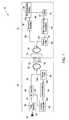
- FIG. 1is a block diagram representation of a system 10 for contactless power transfer in an implantable device 12 including a two channel field-focusing element 14 in accordance with an embodiment of the invention.
- the implantable device 12may include a cardiac pacemaker, a neurological simulator, a muscle simulator, or a cochlear implant.
- the system 10further includes a charging device 16 .
- the charging device 16includes a power source 18 electrically coupled to a first rectifier 20 that converts AC power 22 received from the power source 18 to DC power 24 .
- the DC power 24 provided by the first rectifier 20is supplied to a high frequency inverter 26 .
- the high frequency inverter 26converts the DC power 24 to high frequency AC power 28 .
- the frequency of AC power 28includes frequencies that generate minimum heating of human body tissues.
- the high frequency AC powerhas a frequency of at least 1 MHz.
- the high frequency AC power 28is further transmitted to a first coil 30 provided in the charging device 16 .
- the first coil 30receives the high frequency AC power 28 and generates a magnetic field 32 based on the high frequency AC power 28 .
- the charging device 16may include a stationary charging device or a portable charging device.
- the magnetic field 32is focused on to a second coil 34 provided in the implantable device 12 via a field-focusing element 14 disposed between the first coil 30 and the second coil 34 .
- the field-focusing element 14is situated within the implantable device 16 .
- the field-focusing element 14acts as a self-resonant coil having a standing wave current distribution to focus the magnetic field 32 on to the second coil 34 and enhances the coupling between the first coil 30 and the second coil 34 as described in commonly assigned U.S. patent application Ser. No. 12/731,497, filed on Mar. 25, 2010 and U.S. patent application Ser. No. 12/914,512, filed on Oct. 28, 2010, which are hereby incorporated by reference in their entirety.
- the field-focusing element 14includes at least one resonator.
- the at least one resonatormay be configured to focus at least one of an electric field, a magnetic field, or an electromagnetic field.
- the at least one resonatorincludes a split ring structure, a circular loop structure, a Koch fractal, an omega structure, or a spiral structure.
- the at least one resonatoris disposed within at least one of a dielectric medium, a magnetic medium, or a magneto-dielectric medium.
- the at least one resonatorincludes a plurality of resonators with at least two of the plurality of resonators having different resonant frequencies. In one embodiment, the different resonant frequencies enable transfer of power and data signals simultaneously.
- the second coil 34 disposed within the implantable device 16receives the high frequency AC power 28 from the first coil 30 via the magnetic field 32 generated by the first coil 30 .
- the first coil 30 and the second coil 34are disposed at a distance within a range of about 15 millimeters to about 5 centimeters during the contactless power transfer.
- the second coil 34transfers the high frequency AC power 28 to the rechargeable battery 36 electrically coupled to the second coil 34 within the implantable device 16 .
- a second rectifier 38may be disposed between the second coil 34 and the rechargeable battery 36 to receive the high frequency AC power 28 from the second coil 34 and convert the AC power 28 to DC power 40 before transferring the DC power 40 to the rechargeable battery 36 .
- the DC power 40 transferred to the rechargeable battery 36is within a range of about 1 microwatt to about 900 milliwatts.
- the rechargeable battery 36is coupled to a battery management system (BMS) 42 that manages the charging of the rechargeable battery 36 .
- BMSbattery management system
- the BMS 42tracks signals 48 representative of the power levels in the rechargeable battery 36 and calculates the power and time required to charge the rechargeable battery 36 .
- the BMS 42regulates a voltage of the DC power 40 entering the rechargeable battery 36 .
- the BMS 42communicates with the high frequency inverter 26 disposed within the charging device 16 to provide data 44 related to the voltage and charge level of the rechargeable battery 36 .
- the BMS 42is communicatively coupled to a high frequency modulator 46 that receives the data signals 44 generated by the BMS 42 and modulates the data signals 44 to provide modulated data signals 50 .
- the high frequency modulator 46is coupled to the second coil 34 .
- the second coil 34converts the modulated data signals 50 to a data magnetic field 52 that is focused on the first coil 30 via the field-focusing element 14 .
- the field-focusing element 14includes a two channel field-focusing element including one unidirectional channel to transfer the AC power 28 and a second channel to transfer the data signals 44 .
- a power filter 53may be disposed between the second coil 34 and the high frequency modulator 46 to isolate the high frequency AC power 28 received from the first coil 30 from the high frequency modulator 46 .
- the first coil 30receives the data magnetic field 52 and transfers signals 150 which are representative of the modulated data signals 50 to a demodulator 54 .
- a power filter 56 at the charging device 16may be used to restrict the high frequency AC power 28 within the first coil 30 from entering the demodulator 54 .
- the demodulator 54extracts signals 144 representative of the data signals 44 from the modulated data signals 150 and transfers the data signals 144 to an inverter controller 58 .
- the inverter controller 58controls the voltage and frequency of power at which the high frequency inverter 26 operates in the charging device 16 by providing control signals 60 based on the data signals 144 .
- the inverter controller 58identifies the voltage and the charge status from the data signals 144 and regulates the inverter operation accordingly to provide desired charging to the rechargeable battery 36 .
- FIG. 2is a block diagram representation of an alternate configuration of the system 10 for contactless power transfer in an implantable device 12 including the two channel field-focusing element 14 electrically coupled to the first coil 30 in accordance with an embodiment of the invention.
- the field-focusing element 14is situated within the charging device 16 rather than within the implantable device.
- FIG. 3is a block diagram representation of another alternate configuration of the system 10 for contactless power transfer in an implantable device 12 including a two channel field focusing element 14 configured to transfer data signals 44 from battery management system 42 as well as operational data 43 from a controller 45 to an electronic device 47 for medical analysis in accordance with an embodiment of the invention.
- the implantable device 12includes the controller 45 , and the controller 45 monitors and controls the operation of the implantable device 12 and stores the operational data 43 .
- the operational data 43may be used for further analysis such as, for example, prognostic health monitoring of the implantable device 12 .
- the controller 45transfers the operational data 43 to a multiplexer 49 that multiplexes the operational data 43 along with the data signals 44 transferred by the BMS 42 to the multiplexer 49 .
- the multiplexer 49generates a multiplexed signal 51 that is transferred to the high frequency modulator 46 for modulation and is further transmitted to the first coil 30 .
- the first coil 30receives the multiplexed signal 151 representative of the multiplexed signal 51 in the implantable device and transfers the multiplexed signal 151 to a de-multiplexer 55 after demodulation by the de-modulator 54 as described above.
- the de-multiplexer 55separates the operational data 143 and the data signals 144 from the multiplexed signal 151 representative of the operational data 43 and the data signals 44 in the implantable device 12 respectively.
- the data signals 144are transferred to the inverter controller 58 as described above and the operational data 143 may be transferred to the electronic device 47 provided outside the charging device 16 for further analysis.
- FIG. 4is a block diagram representation of a system 10 for contactless power transfer in the implantable device 12 including a single channel field-focusing element 62 in accordance with an embodiment of the invention.
- the single channel field-focusing element 62focuses high frequency AC power 28 from the first coil 30 to the second coil 34 but, in contrast to the embodiments of FIGS. 1 and 2 , does not transfer modulated data signals 50 from the second coil 34 to the first coil 30 .
- the single channel field-focusing element 62is shown as being situated in the implantable device, the single channel field-focusing element 62 may alternatively be situated in the charging device. In the embodiment of FIG.
- the modulated data signals 50 received from the high frequency modulator 46may be transferred to a RF transmitter antenna 64 disposed within the implantable device 12 .
- the RF transmitter antenna 64transmits the modulated data signals 50 to a RF receiver antenna 66 disposed within the charging device 16 .
- the RF receiver antenna 66receives the modulated data signals 150 representative of the modulated data signals 50 from the implantable device 12 and transfers the modulated data signals 150 to the demodulator 54 for further processing as described above.
- FIG. 5is a block diagram representation an alternate configuration of the system 10 for contactless power transfer in the implantable device 12 wherein no data is required to be transmitted back to the charging device 16 .
- the system 10includes the single channel field-focusing element 62 to focus high frequency AC power 28 from the first coil 30 to the second coil 34 .
- the single channel field-focusing element 62is shown as being situated in the charging device, the single channel field-focusing element 62 may alternatively be situated in the implantable device.
- the high frequency AC power 28 from second coil 34is converted to DC power by the second rectifier 38 , which is transferred to a DC-DC converter 68 , which provides DC power 40 .
- the DC power 40is fed to the rechargeable battery 36 for charging.
- the rechargeable battery 36is coupled to the BMS 42 that regulates the charging of the rechargeable battery 36 .
- the BMS 42is coupled to the DC-DC converter 68 via a feedback loop to regulate the voltage of the DC power 40 entering the rechargeable battery 36 in the implantable device 12 .
- the DC-DC converter 68receives the data signals 44 from the BMS 42 via the feedback loop and adjusts accordingly to provide optimum charging to the rechargeable battery 36 .
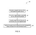
- FIG. 6is a flow chart representing the steps involved in a method 80 for contactless charging of a rechargeable battery disposed in an implantable device in accordance with an embodiment of the invention.
- the method 80includes generating a magnetic field via a first coil coupled to a power source in step 82 .
- the magnetic field generated by the first coilis focused to a second coil by employing a field-focusing element in step 84 .
- the first coil and the second coilare disposed at a distance within a range of about 15 millimeter to about 5 centimeters prior to focusing the magnetic field.
- the first coiltransfers power to the second coil via the magnetic field in step 86 .
- the poweris transferred from the first coil to the second coil within a range of about 1 microwatt to about 900 milliwatts.
- the power from the second coilis transmitted to the rechargeable battery disposed within the implantable device in step 88 .
- data signals regarding the implantable device, the state of charge of the rechargeable battery, or bothare obtained and transferred through the field-focusing element, first coil and the second coil to a processor situated outside of the implantable device.
- the processis facilitated by having the power and the data signals from the rechargeable battery and implantable device respectively transferred at different resonant frequencies.
- data transfereither is not required or is accomplished via RF transmission.
- the various embodiments of the systems for contactless power transfer in implantable devices described aboveinclude a power source, a first coil, a field focusing element and a second coil that enable transfer of power via a contactless medium from the first coil to the second coil.
- the contactless power transfer systemenables efficient contactless power transfer between the charging device provided outside the human body and the implantable device disposed inside the human body, for example.
- the contactless power transfer systemalso maintains the efficiency in case of multiple layers of flesh provided between the first coil and the second coil. This provides a non-destructive method for charging the rechargeable battery disposed within the implantable device and reduces costs and risks to human life during operations.
Landscapes
- Engineering & Computer Science (AREA)
- Computer Networks & Wireless Communication (AREA)
- Power Engineering (AREA)
- Health & Medical Sciences (AREA)
- Signal Processing (AREA)
- General Health & Medical Sciences (AREA)
- Radiology & Medical Imaging (AREA)
- Life Sciences & Earth Sciences (AREA)
- Animal Behavior & Ethology (AREA)
- Public Health (AREA)
- Veterinary Medicine (AREA)
- Nuclear Medicine, Radiotherapy & Molecular Imaging (AREA)
- Biomedical Technology (AREA)
- Physics & Mathematics (AREA)
- General Physics & Mathematics (AREA)
- Medical Informatics (AREA)
- Mathematical Physics (AREA)
- Algebra (AREA)
- Computational Mathematics (AREA)
- Chemical & Material Sciences (AREA)
- Mathematical Analysis (AREA)
- Mathematical Optimization (AREA)
- Medicinal Chemistry (AREA)
- Pure & Applied Mathematics (AREA)
- Business, Economics & Management (AREA)
- Educational Administration (AREA)
- Educational Technology (AREA)
- Theoretical Computer Science (AREA)
- Charge And Discharge Circuits For Batteries Or The Like (AREA)
- Electrotherapy Devices (AREA)
- Prostheses (AREA)
Abstract
Description
Claims (17)
Priority Applications (6)
| Application Number | Priority Date | Filing Date | Title |
|---|---|---|---|
| US13/052,196US8849402B2 (en) | 2011-03-21 | 2011-03-21 | System and method for contactless power transfer in implantable devices |
| KR1020137024950AKR102013964B1 (en) | 2011-03-21 | 2012-03-16 | System and method for contactless power transfer in implantable devices |
| EP12712027.7AEP2688643B1 (en) | 2011-03-21 | 2012-03-16 | System and method for contactless power transfer in implantable devices |
| JP2014501153AJP5990252B2 (en) | 2011-03-21 | 2012-03-16 | System and method for contactless power transfer in an implantable device |
| PCT/US2012/029326WO2012129061A1 (en) | 2011-03-21 | 2012-03-16 | System and method for contactless power transfer in implantable devices |
| CN201280014305.7ACN103517735B (en) | 2011-03-21 | 2012-03-16 | For the system and method for non-contact power transfer in implantable device |
Applications Claiming Priority (1)
| Application Number | Priority Date | Filing Date | Title |
|---|---|---|---|
| US13/052,196US8849402B2 (en) | 2011-03-21 | 2011-03-21 | System and method for contactless power transfer in implantable devices |
Publications (2)
| Publication Number | Publication Date |
|---|---|
| US20120245649A1 US20120245649A1 (en) | 2012-09-27 |
| US8849402B2true US8849402B2 (en) | 2014-09-30 |
Family
ID=45929028
Family Applications (1)
| Application Number | Title | Priority Date | Filing Date |
|---|---|---|---|
| US13/052,196Active2032-02-14US8849402B2 (en) | 2011-03-21 | 2011-03-21 | System and method for contactless power transfer in implantable devices |
Country Status (6)
| Country | Link |
|---|---|
| US (1) | US8849402B2 (en) |
| EP (1) | EP2688643B1 (en) |
| JP (1) | JP5990252B2 (en) |
| KR (1) | KR102013964B1 (en) |
| CN (1) | CN103517735B (en) |
| WO (1) | WO2012129061A1 (en) |
Cited By (2)
| Publication number | Priority date | Publication date | Assignee | Title |
|---|---|---|---|---|
| US10355512B2 (en) | 2015-07-23 | 2019-07-16 | Medtronic, Inc. | Focused power transfer for implantable medical device |
| CN110164265A (en)* | 2019-05-15 | 2019-08-23 | 河海大学 | A kind of vertical longitudinal wave stationary wave experiment measuring device and method |
Families Citing this family (54)
| Publication number | Priority date | Publication date | Assignee | Title |
|---|---|---|---|---|
| US8674550B2 (en) | 2010-03-25 | 2014-03-18 | General Electric Company | Contactless power transfer system and method |
| KR101688948B1 (en)* | 2011-05-27 | 2016-12-22 | 엘지전자 주식회사 | Establishing a data communication connection using a wireless power transmission |
| US9287040B2 (en) | 2012-07-27 | 2016-03-15 | Thoratec Corporation | Self-tuning resonant power transfer systems |
| WO2014018971A1 (en) | 2012-07-27 | 2014-01-30 | Thoratec Corporation | Resonant power transfer systems with protective algorithm |
| WO2014018973A1 (en) | 2012-07-27 | 2014-01-30 | Thoratec Corporation | Resonant power transmission coils and systems |
| EP4257174A3 (en) | 2012-07-27 | 2023-12-27 | Tc1 Llc | Thermal management for implantable wireless power transfer systems |
| US10383990B2 (en) | 2012-07-27 | 2019-08-20 | Tc1 Llc | Variable capacitor for resonant power transfer systems |
| WO2014018969A2 (en) | 2012-07-27 | 2014-01-30 | Thoratec Corporation | Resonant power transfer system and method of estimating system state |
| WO2014018974A1 (en) | 2012-07-27 | 2014-01-30 | Thoratec Corporation | Magnetic power transmission utilizing phased transmitter coil arrays and phased receiver coil arrays |
| US10291067B2 (en) | 2012-07-27 | 2019-05-14 | Tc1 Llc | Computer modeling for resonant power transfer systems |
| US9697951B2 (en)* | 2012-08-29 | 2017-07-04 | General Electric Company | Contactless power transfer system |
| US20140114373A1 (en)* | 2012-10-22 | 2014-04-24 | Boston Scientific Neuromodulation Corporation | Intermediate Coupler to Facilitate Charging in an Implantable Medical Device System |
| WO2014145664A1 (en) | 2013-03-15 | 2014-09-18 | Thoratec Corporation | Integrated implantable tets housing including fins and coil loops |
| EP2984731B8 (en) | 2013-03-15 | 2019-06-26 | Tc1 Llc | Malleable tets coil with improved anatomical fit |
| AU2013387134B2 (en)* | 2013-04-15 | 2017-01-19 | T&W Engineering A/S | ECG monitor with an implantable part |
| CA2916241C (en)* | 2013-05-22 | 2023-07-04 | Deep Brain Innovations LLC | Deep brain stimulator and method of use |
| AU2014296322B2 (en) | 2013-07-29 | 2020-01-16 | Alfred E. Mann Foundation For Scientific Research | High efficiency magnetic link for implantable devices |
| US9780596B2 (en) | 2013-07-29 | 2017-10-03 | Alfred E. Mann Foundation For Scientific Research | Microprocessor controlled class E driver |
| CN103560572B (en)* | 2013-10-18 | 2016-06-01 | 北京航空航天大学 | A kind of implantable cardiac pacemaker magnetic coupling resonance wireless charging device |
| US10695476B2 (en)* | 2013-11-11 | 2020-06-30 | Tc1 Llc | Resonant power transfer systems with communications |
| EP3069358B1 (en) | 2013-11-11 | 2019-06-12 | Tc1 Llc | Hinged resonant power transfer coil |
| EP3072210B1 (en) | 2013-11-11 | 2023-12-20 | Tc1 Llc | Resonant power transfer systems with communications |
| CN104158237B (en)* | 2014-01-20 | 2017-02-08 | 中国海洋大学 | Cardiac pacemaker wireless charging method and apparatus based on magnetic resonance |
| WO2015134871A1 (en) | 2014-03-06 | 2015-09-11 | Thoratec Corporation | Electrical connectors for implantable devices |
| GB2527075A (en) | 2014-03-17 | 2015-12-16 | Daassist As | Percutaneous system, devices and methods |
| US9780575B2 (en) | 2014-08-11 | 2017-10-03 | General Electric Company | System and method for contactless exchange of power |
| EP3826104B1 (en) | 2014-09-22 | 2023-05-03 | Tc1 Llc | Antenna designs for communication between a wirelessly powered implant to an external device outside the body |
| WO2016057525A1 (en) | 2014-10-06 | 2016-04-14 | Thoratec Corporation | Multiaxial connector for implantable devices |
| CN107106075B (en)* | 2014-10-09 | 2020-06-30 | 通用电气公司 | Method and system for contactless power transfer in a gate driver unit |
| US10052492B2 (en)* | 2015-05-06 | 2018-08-21 | Verily Life Sciences Llc | Replaceable battery for implantable devices |
| WO2017025606A1 (en)* | 2015-08-12 | 2017-02-16 | Nuheart As | System, apparatus and method for improved contactless power transfer in implantable devices |
| US10148126B2 (en) | 2015-08-31 | 2018-12-04 | Tc1 Llc | Wireless energy transfer system and wearables |
| CN105119357B (en)* | 2015-09-18 | 2018-07-03 | 国网上海市电力公司 | A kind of remote-wireless charging equipment |
| WO2017062552A1 (en) | 2015-10-07 | 2017-04-13 | Tc1 Llc | Resonant power transfer systems having efficiency optimization based on receiver impedance |
| US9931515B2 (en)* | 2015-12-17 | 2018-04-03 | Novartis Ag | Powered case for electro-active medical device battery management |
| US10893847B2 (en) | 2015-12-30 | 2021-01-19 | Nuheart As | Transcatheter insertion system |
| EP4084271A1 (en) | 2016-09-21 | 2022-11-02 | Tc1 Llc | Systems and methods for locating implanted wireless power transmission devices |
| US10335528B2 (en) | 2016-10-07 | 2019-07-02 | Nuheart As | Transcatheter method and system for the delivery of intracorporeal devices |
| US10537672B2 (en) | 2016-10-07 | 2020-01-21 | Nuheart As | Transcatheter device and system for the delivery of intracorporeal devices |
| KR102718580B1 (en)* | 2016-12-21 | 2024-10-17 | 삼성전자주식회사 | Method and appartus for wireless power transfer |
| KR20180076635A (en)* | 2016-12-28 | 2018-07-06 | (주)뉴옵틱스 | Deep brain stimulation and wireless power transmission method thereof |
| WO2018136592A2 (en) | 2017-01-18 | 2018-07-26 | Tc1 Llc | Systems and methods for transcutaneous power transfer using microneedles |
| US10537670B2 (en) | 2017-04-28 | 2020-01-21 | Nuheart As | Ventricular assist device and method |
| US10888646B2 (en) | 2017-04-28 | 2021-01-12 | Nuheart As | Ventricular assist device and method |
| WO2019135890A1 (en) | 2018-01-04 | 2019-07-11 | Tc1 Llc | Systems and methods for elastic wireless power transmission devices |
| EP3512087B1 (en) | 2018-01-12 | 2023-01-25 | STMicroelectronics S.r.l. | A galvanically isolated dc-dc converter circuit with data communication, corresponding system and corresponding method |
| IT201800004174A1 (en) | 2018-04-03 | 2019-10-03 | GALVANIC INSULATION CIRCUIT AND SYSTEM, CORRESPONDING PROCEDURE | |
| CN108718114A (en)* | 2018-06-07 | 2018-10-30 | 北京航空航天大学 | Implantable device and its wireless power transmission device |
| US11642537B2 (en) | 2019-03-11 | 2023-05-09 | Axonics, Inc. | Charging device with off-center coil |
| US11482888B2 (en) | 2020-06-19 | 2022-10-25 | Medtronic, Inc. | Antenna for use with RF energy harvesting |
| US20210393968A1 (en)* | 2020-06-19 | 2021-12-23 | Medtronic, Inc. | Radio frequency energy harvesting |
| WO2022123531A1 (en)* | 2020-12-10 | 2022-06-16 | Cochlear Limited | Antenna arrangements |
| KR102524396B1 (en)* | 2021-05-03 | 2023-04-24 | 주식회사 토닥 | Cochlear implant system using a compatible external device |
| IT202200015774A1 (en)* | 2022-07-26 | 2024-01-26 | Asmundis Carlo De | IMPLANTABLE DEVICE, MEDICAL SYSTEM COMPRISING SAID DEVICE AND METHOD OF RECHARGING THE IMPLANTABLE DEVICE AND THE MEDICAL SYSTEM |
Citations (15)
| Publication number | Priority date | Publication date | Assignee | Title |
|---|---|---|---|---|
| US5690693A (en) | 1995-06-07 | 1997-11-25 | Sulzer Intermedics Inc. | Transcutaneous energy transmission circuit for implantable medical device |
| US6960968B2 (en) | 2002-06-26 | 2005-11-01 | Koninklijke Philips Electronics N.V. | Planar resonator for wireless power transfer |
| WO2007008646A2 (en) | 2005-07-12 | 2007-01-18 | Massachusetts Institute Of Technology | Wireless non-radiative energy transfer |
| US7323964B1 (en) | 2006-11-23 | 2008-01-29 | National Central University | Non-contact power system with load and gap detection |
| US20080240358A1 (en) | 2007-03-30 | 2008-10-02 | General Electric Company | Wireless X-ray detector power system and method |
| US20080265684A1 (en) | 2006-10-25 | 2008-10-30 | Laszlo Farkas | High power wireless resonant energy transfer system |
| US20080312852A1 (en) | 2004-11-08 | 2008-12-18 | Koninklijke Philips Electronics N.V. | Wireless Battery Status Management for Medical Devices |
| US7471986B2 (en) | 2004-02-20 | 2008-12-30 | Cardiac Pacemakers, Inc. | System and method for transmitting energy to and establishing a communications network with one or more implanted devices |
| JP2009106136A (en) | 2007-10-25 | 2009-05-14 | Toyota Motor Corp | Electric vehicle and vehicle power supply device |
| US20100148589A1 (en) | 2008-10-01 | 2010-06-17 | Hamam Rafif E | Efficient near-field wireless energy transfer using adiabatic system variations |
| US20100204756A1 (en)* | 2009-02-10 | 2010-08-12 | Boston Scientific Neuromodulation Corporation | External Device for Communicating with an Implantable Medical Device Having Data Telemetry and Charging Integrated in a Single Housing |
| US20100237709A1 (en) | 2008-09-27 | 2010-09-23 | Hall Katherine L | Resonator arrays for wireless energy transfer |
| US20100308939A1 (en) | 2008-09-27 | 2010-12-09 | Kurs Andre B | Integrated resonator-shield structures |
| US20110140429A1 (en) | 2010-10-28 | 2011-06-16 | General Electric Company | Systems for contactless power transfer |
| EP2369711A2 (en) | 2010-03-25 | 2011-09-28 | General Electric Company | Contactless power transfer system and method |
Family Cites Families (5)
| Publication number | Priority date | Publication date | Assignee | Title |
|---|---|---|---|---|
| US6120502A (en)* | 1988-06-13 | 2000-09-19 | Michelson; Gary Karlin | Apparatus and method for the delivery of electrical current for interbody spinal arthrodesis |
| EP1948296B2 (en)* | 2005-10-14 | 2017-10-11 | Pacesetter, Inc. | Leadless cardiac pacemaker and system |
| KR20110117732A (en)* | 2007-03-27 | 2011-10-27 | 메사추세츠 인스티튜트 오브 테크놀로지 | Wireless energy transfer |
| EP3179640A1 (en)* | 2008-09-27 | 2017-06-14 | WiTricity Corporation | Wireless energy transfer systems |
| JP5324901B2 (en)* | 2008-12-09 | 2013-10-23 | 日立コンシューマエレクトロニクス株式会社 | Non-contact power transmission system |
- 2011
- 2011-03-21USUS13/052,196patent/US8849402B2/enactiveActive
- 2012
- 2012-03-16JPJP2014501153Apatent/JP5990252B2/enactiveActive
- 2012-03-16CNCN201280014305.7Apatent/CN103517735B/enactiveActive
- 2012-03-16KRKR1020137024950Apatent/KR102013964B1/enactiveActive
- 2012-03-16EPEP12712027.7Apatent/EP2688643B1/enactiveActive
- 2012-03-16WOPCT/US2012/029326patent/WO2012129061A1/enunknown
Patent Citations (15)
| Publication number | Priority date | Publication date | Assignee | Title |
|---|---|---|---|---|
| US5690693A (en) | 1995-06-07 | 1997-11-25 | Sulzer Intermedics Inc. | Transcutaneous energy transmission circuit for implantable medical device |
| US6960968B2 (en) | 2002-06-26 | 2005-11-01 | Koninklijke Philips Electronics N.V. | Planar resonator for wireless power transfer |
| US7471986B2 (en) | 2004-02-20 | 2008-12-30 | Cardiac Pacemakers, Inc. | System and method for transmitting energy to and establishing a communications network with one or more implanted devices |
| US20080312852A1 (en) | 2004-11-08 | 2008-12-18 | Koninklijke Philips Electronics N.V. | Wireless Battery Status Management for Medical Devices |
| WO2007008646A2 (en) | 2005-07-12 | 2007-01-18 | Massachusetts Institute Of Technology | Wireless non-radiative energy transfer |
| US20080265684A1 (en) | 2006-10-25 | 2008-10-30 | Laszlo Farkas | High power wireless resonant energy transfer system |
| US7323964B1 (en) | 2006-11-23 | 2008-01-29 | National Central University | Non-contact power system with load and gap detection |
| US20080240358A1 (en) | 2007-03-30 | 2008-10-02 | General Electric Company | Wireless X-ray detector power system and method |
| JP2009106136A (en) | 2007-10-25 | 2009-05-14 | Toyota Motor Corp | Electric vehicle and vehicle power supply device |
| US20100237709A1 (en) | 2008-09-27 | 2010-09-23 | Hall Katherine L | Resonator arrays for wireless energy transfer |
| US20100308939A1 (en) | 2008-09-27 | 2010-12-09 | Kurs Andre B | Integrated resonator-shield structures |
| US20100148589A1 (en) | 2008-10-01 | 2010-06-17 | Hamam Rafif E | Efficient near-field wireless energy transfer using adiabatic system variations |
| US20100204756A1 (en)* | 2009-02-10 | 2010-08-12 | Boston Scientific Neuromodulation Corporation | External Device for Communicating with an Implantable Medical Device Having Data Telemetry and Charging Integrated in a Single Housing |
| EP2369711A2 (en) | 2010-03-25 | 2011-09-28 | General Electric Company | Contactless power transfer system and method |
| US20110140429A1 (en) | 2010-10-28 | 2011-06-16 | General Electric Company | Systems for contactless power transfer |
Non-Patent Citations (13)
| Title |
|---|
| Adnan Bohori et al.; Title : Contactless Power Transfer System and Method; U.S. Appl. No. 12/731,497, filed Mar. 25, 2010; 27 Pages. |
| Adnan Bohori et al.; Title : Contactless Power Transfer System; Filed on Apr. 28, 2011; U.S. Appl. No. 12/845,133; 24 Pages. |
| Adnan Bohori et al.; Title : Contactless Power Transfer System; U.S. Appl. No. 12/820,208, filed Jun. 22, 2010; 18 Pages. |
| Adnan Bohori et al.; Title : Contactless Power Transfer System; U.S. Appl. No. 12/845,133, filed Jul. 28, 2010; 34 Pages. |
| Adnan Bohori et al.; Title : Power Transfer System and Method; U.S. Appl. No. 12/822,232, filed Jun. 24, 2010; 19 Pages. |
| Adnan Bohori et al.; Title : System and Method for Contactless Power Transfer in Portable Image Detectors; U.S. Appl. No. 13/149,170, filed Jun. 24, 2010; 19 Pages. |
| Adnan Bohori et al.; Title : Systems for Contactless Power Transfer; U.S. Appl. No. 12/914,512, filed Oct. 28, 2010; 17 Pages. |
| Aristeidis Karalis, J.D. Joannopoulos, Marin Soljac; Title : Efficient wireless non-radiative mid-range energy transfer; Annals of Physics 323 (2008) 34-48. |
| Search Report and Written Opinion from corresponding PCT Application No. PCT/US2012/029326 dated Jun. 27, 2012. |
| Shahrzad Jalali Mazlouman, Alireza Mahanfar, Bozena Kaminska; Title: Mid-range Wireless Energy Transfer Using Inductive Resonance for Wireless Sensors; 6 Pages, IEEE International Conference on Computer Design, 2009, ICCD 2009, Oct. 4-7, 2009, Lake Tahoe, CA, pp. 517-522, Digital Object Identifier :10.1109/ICCD.2009.5413106. |
| Stephen Paul Fenton et al.; Title : Electrical Coupling Apparatus and Method; U.S. Appl. No. 12/778,475, filed May 12, 2010; 12 Pages. |
| Zhang et al., "Wireless Energy Transfer Platform for Medical Sensors and Implantable Devices", Engineering in Medicine and Biology Society, Sep. 3-6, 2009, Minneapolis, Minnesota; pp. 1045-1048. |
| Zhu et al., "Ultrasonic Energy Transmission and Conversion Using a 2-D MEMS Resonator", Electron Device Letters, vol. 31, Issue 4, Apr. 2010, pp. 374-376. |
Cited By (3)
| Publication number | Priority date | Publication date | Assignee | Title |
|---|---|---|---|---|
| US10355512B2 (en) | 2015-07-23 | 2019-07-16 | Medtronic, Inc. | Focused power transfer for implantable medical device |
| CN110164265A (en)* | 2019-05-15 | 2019-08-23 | 河海大学 | A kind of vertical longitudinal wave stationary wave experiment measuring device and method |
| CN110164265B (en)* | 2019-05-15 | 2021-04-27 | 河海大学 | A vertical longitudinal wave standing wave experimental measurement device and method |
Also Published As
| Publication number | Publication date |
|---|---|
| JP2014510511A (en) | 2014-04-24 |
| EP2688643B1 (en) | 2019-03-13 |
| CN103517735A (en) | 2014-01-15 |
| WO2012129061A1 (en) | 2012-09-27 |
| EP2688643A1 (en) | 2014-01-29 |
| US20120245649A1 (en) | 2012-09-27 |
| KR102013964B1 (en) | 2019-08-23 |
| CN103517735B (en) | 2016-01-20 |
| KR20140007447A (en) | 2014-01-17 |
| JP5990252B2 (en) | 2016-09-07 |
Similar Documents
| Publication | Publication Date | Title |
|---|---|---|
| US8849402B2 (en) | System and method for contactless power transfer in implantable devices | |
| CN102810898B (en) | The system and method for non-contact power transfer in portable image detector | |
| Ahn et al. | Wireless power transfer with automatic feedback control of load resistance transformation | |
| CN103748763B (en) | Implantable medical device and Poewr control method thereof | |
| US9728981B2 (en) | Feedback controlled coil driver for inductive power transfer | |
| US10376624B2 (en) | Transcutaneous energy transfer systems | |
| KR101947980B1 (en) | Method and apparatus for wireless power transmission and wireless power reception apparatus | |
| US8825173B2 (en) | Method and apparatus for supplying energy to a medical device | |
| EP2648800B1 (en) | Portable power charging of implantable medical devices | |
| CN107376121B (en) | Percutaneous wireless charging system and method with adaptive transmission power adjustment function | |
| KR20160043972A (en) | multiband wireless power system | |
| CN103262435A (en) | Magnetic induction communication system for implantable medical device | |
| US20250118994A1 (en) | Electric energy transmission system, and flexible electric energy repeater, relay resonance coil, in-vitro energy controller and in-vivo electric energy receiver thereof | |
| US20170040841A1 (en) | Implantable medical device charging | |
| WO2017123422A1 (en) | Methods and apparatus for wirelessly transferring power | |
| KR101630928B1 (en) | The wireless system transferring electric power to organ transplanted to human, the transplanted organ transferred electric power on wireless medium and the method transferring electric power to organ transplanted to human | |
| US20180199854A1 (en) | Voice control system for an implant | |
| KR20140036953A (en) | Method and apparatus for wireless power reception and method and apparatus for wireless power transmission and wireless power transmission system | |
| Newaskar | WIRELESS CHARGER FOR BIOMEDICAL DEVICES | |
| KR20120134072A (en) | System and method for contactless power transfer in portable image detectors | |
| Schelles et al. | Comparison and System Development of a 2-coil and 3-coil Inductive Link for Transcutaneous Power Transfer | |
| Swain et al. | Development of miniature wireless energy transfer system for implantable pressure sensor | |
| Singh et al. | Green Energy Efficient Wired and Wireless Charging Techniques for IoT Enabled Healthcare Systems | |
| Obais et al. | Design of Wireless Biotelemetry Powering System for Implanted Sensing Devices in Human Body | |
| Liu | Waveform-optimized wireless power transfer for implantable medical devices |
Legal Events
| Date | Code | Title | Description |
|---|---|---|---|
| AS | Assignment | Owner name:GENERAL ELECTRIC COMPANY, NEW YORK Free format text:ASSIGNMENT OF ASSIGNORS INTEREST;ASSIGNORS:BOHORI, ADNAN KUTUBUDDIN;RAMACHANDRAPANICKER, SOMAKUMAR;BHAT, SUMA MEMANA NARAYANA;REEL/FRAME:025987/0912 Effective date:20110315 | |
| FEPP | Fee payment procedure | Free format text:PAYOR NUMBER ASSIGNED (ORIGINAL EVENT CODE: ASPN); ENTITY STATUS OF PATENT OWNER: LARGE ENTITY | |
| STCF | Information on status: patent grant | Free format text:PATENTED CASE | |
| MAFP | Maintenance fee payment | Free format text:PAYMENT OF MAINTENANCE FEE, 4TH YEAR, LARGE ENTITY (ORIGINAL EVENT CODE: M1551) Year of fee payment:4 | |
| MAFP | Maintenance fee payment | Free format text:PAYMENT OF MAINTENANCE FEE, 8TH YEAR, LARGE ENTITY (ORIGINAL EVENT CODE: M1552); ENTITY STATUS OF PATENT OWNER: LARGE ENTITY Year of fee payment:8 | |
| AS | Assignment | Owner name:EDISON INNOVATIONS, LLC, TEXAS Free format text:ASSIGNMENT OF ASSIGNORS INTEREST;ASSIGNOR:DOLBY INTELLECTUAL PROPERTY LICENSING, LLC;REEL/FRAME:070293/0273 Effective date:20250219 | |
| AS | Assignment | Owner name:GE INTELLECTUAL PROPERTY LICENSING, LLC, NEW YORK Free format text:ASSIGNMENT OF ASSIGNORS INTEREST;ASSIGNOR:GENERAL ELECTRIC COMPANY;REEL/FRAME:070636/0815 Effective date:20240630 Owner name:DOLBY INTELLECTUAL PROPERTY LICENSING, LLC, NEW YORK Free format text:CHANGE OF NAME;ASSIGNOR:GE INTELLECTUAL PROPERTY LICENSING, LLC;REEL/FRAME:070643/0907 Effective date:20240819 |