US8847833B2 - Loop resonator apparatus and methods for enhanced field control - Google Patents
Loop resonator apparatus and methods for enhanced field controlDownload PDFInfo
- Publication number
- US8847833B2 US8847833B2US12/649,231US64923109AUS8847833B2US 8847833 B2US8847833 B2US 8847833B2US 64923109 AUS64923109 AUS 64923109AUS 8847833 B2US8847833 B2US 8847833B2
- Authority
- US
- United States
- Prior art keywords
- pwb
- antenna
- loop
- location
- resonator
- Prior art date
- Legal status (The legal status is an assumption and is not a legal conclusion. Google has not performed a legal analysis and makes no representation as to the accuracy of the status listed.)
- Expired - Fee Related, expires
Links
- 238000000034methodMethods0.000titleabstractdescription39
- 230000005684electric fieldEffects0.000claimsabstractdescription46
- 239000000758substrateSubstances0.000claimsdescription9
- 238000009826distributionMethods0.000abstractdescription35
- 230000013707sensory perception of soundEffects0.000abstractdescription22
- 238000004519manufacturing processMethods0.000abstractdescription5
- 230000001939inductive effectEffects0.000abstractdescription3
- 238000004088simulationMethods0.000description23
- 239000003990capacitorSubstances0.000description19
- 230000009467reductionEffects0.000description14
- 239000011248coating agentSubstances0.000description10
- 238000000576coating methodMethods0.000description10
- 230000001413cellular effectEffects0.000description9
- 238000004891communicationMethods0.000description7
- 230000006870functionEffects0.000description7
- 238000013461designMethods0.000description6
- 238000013459approachMethods0.000description5
- 239000004020conductorSubstances0.000description5
- 230000008878couplingEffects0.000description5
- 238000010168coupling processMethods0.000description5
- 238000005859coupling reactionMethods0.000description5
- 230000008901benefitEffects0.000description4
- 230000005672electromagnetic fieldEffects0.000description4
- 238000005516engineering processMethods0.000description4
- 238000005259measurementMethods0.000description4
- 230000005404monopoleEffects0.000description4
- 230000008569processEffects0.000description4
- 230000005855radiationEffects0.000description3
- 239000000654additiveSubstances0.000description2
- 230000000996additive effectEffects0.000description2
- 238000003491arrayMethods0.000description2
- 230000003750conditioning effectEffects0.000description2
- 230000007423decreaseEffects0.000description2
- 230000005670electromagnetic radiationEffects0.000description2
- 230000006872improvementEffects0.000description2
- 239000000463materialSubstances0.000description2
- 238000004806packaging method and processMethods0.000description2
- PEZNEXFPRSOYPL-UHFFFAOYSA-N(bis(trifluoroacetoxy)iodo)benzeneChemical compoundFC(F)(F)C(=O)OI(OC(=O)C(F)(F)F)C1=CC=CC=C1PEZNEXFPRSOYPL-UHFFFAOYSA-N0.000description1
- 208000015976Corneal dystrophy-perceptive deafness syndromeDiseases0.000description1
- 229910001218Gallium arsenideInorganic materials0.000description1
- 238000006842Henry reactionMethods0.000description1
- 229910000577Silicon-germaniumInorganic materials0.000description1
- 230000009471actionEffects0.000description1
- 230000004075alterationEffects0.000description1
- 230000005540biological transmissionEffects0.000description1
- 239000000919ceramicSubstances0.000description1
- 230000008859changeEffects0.000description1
- 238000005094computer simulationMethods0.000description1
- 235000009508confectioneryNutrition0.000description1
- 238000012937correctionMethods0.000description1
- 230000001419dependent effectEffects0.000description1
- 230000000779depleting effectEffects0.000description1
- 229920005994diacetyl cellulosePolymers0.000description1
- 230000003467diminishing effectEffects0.000description1
- 230000009977dual effectEffects0.000description1
- 238000005530etchingMethods0.000description1
- 239000004744fabricSubstances0.000description1
- 238000001914filtrationMethods0.000description1
- 239000011521glassSubstances0.000description1
- 230000010354integrationEffects0.000description1
- CNQCVBJFEGMYDW-UHFFFAOYSA-Nlawrencium atomChemical compound[Lr]CNQCVBJFEGMYDW-UHFFFAOYSA-N0.000description1
- 230000007774longtermEffects0.000description1
- 239000010445micaSubstances0.000description1
- 229910052618mica groupInorganic materials0.000description1
- 230000000116mitigating effectEffects0.000description1
- ORQBXQOJMQIAOY-UHFFFAOYSA-NnobeliumChemical compound[No]ORQBXQOJMQIAOY-UHFFFAOYSA-N0.000description1
- 230000003287optical effectEffects0.000description1
- 238000005457optimizationMethods0.000description1
- 239000000123paperSubstances0.000description1
- 230000002093peripheral effectEffects0.000description1
- 239000002985plastic filmSubstances0.000description1
- 229920006255plastic filmPolymers0.000description1
- 238000012545processingMethods0.000description1
- 238000003672processing methodMethods0.000description1
- 238000004549pulsed laser depositionMethods0.000description1
- 238000007493shaping processMethods0.000description1
- 239000007787solidSubstances0.000description1
- 238000003860storageMethods0.000description1
- 238000006467substitution reactionMethods0.000description1
- 238000012546transferMethods0.000description1
- 230000009466transformationEffects0.000description1
Images


Classifications
- H—ELECTRICITY
- H01—ELECTRIC ELEMENTS
- H01Q—ANTENNAS, i.e. RADIO AERIALS
- H01Q7/00—Loop antennas with a substantially uniform current distribution around the loop and having a directional radiation pattern in a plane perpendicular to the plane of the loop
- H—ELECTRICITY
- H01—ELECTRIC ELEMENTS
- H01Q—ANTENNAS, i.e. RADIO AERIALS
- H01Q1/00—Details of, or arrangements associated with, antennas
- H01Q1/27—Adaptation for use in or on movable bodies
- H01Q1/273—Adaptation for carrying or wearing by persons or animals
- H—ELECTRICITY
- H01—ELECTRIC ELEMENTS
- H01Q—ANTENNAS, i.e. RADIO AERIALS
- H01Q1/00—Details of, or arrangements associated with, antennas
- H01Q1/48—Earthing means; Earth screens; Counterpoises
- H—ELECTRICITY
- H01—ELECTRIC ELEMENTS
- H01Q—ANTENNAS, i.e. RADIO AERIALS
- H01Q9/00—Electrically-short antennas having dimensions not more than twice the operating wavelength and consisting of conductive active radiating elements
- H01Q9/04—Resonant antennas
Definitions
- the present inventionrelates generally to internal antennas for use in portable radio devices and more particularly in one exemplary aspect to a passive loop resonator structure to control antenna ground plane field distribution in order to improve hearing aid compliance, and methods of utilizing and manufacturing the same.
- Internal antennasare an element found in most modern portable radio devices, such as mobile phones, Blackberry® devices, smartphones, personal digital assistants (PDAs), or other personal communication devices (PCD).
- these antennascomprise a planar radiating plane and a ground plane parallel thereto, which are connected to each other by a short-circuit conductor in order to achieve the matching of the antenna.
- the structureis dimensioned so that it functions as a resonator at the operating frequency. It is a common requirement that the antenna operate in more than one frequency band (such as dual band, tri-band, or quad-band mobile phones) in which case two or more resonators are used.
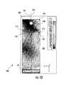
- FIG. 1Ashows a typical configuration of the PWB 100 in a mobile radio device.
- the PWB 100comprises a ground plane 102 , monopole antenna 104 disposed proximate to one end 110 of the PWB (on the opposite side from ground plane 102 ), and an earpiece 108 (speaker) located a distance from the antenna 104 (e.g., on the opposite end from the antenna).
- Such configurationis typically chosen to optimize mobile phone packaging volume, and/or to minimize interference between the antenna active element 104 and earpiece 108 .
- FIG. 1Bdepicts an electromagnetic field distribution across the PWB ground plane 102 that is induced by antenna element 104 of FIG. 1 a , which is modeled as a half wave dipole.
- electrical (E) field maxima 118 and 120are located proximate to the ends 110 and 106 of the PWB longest dimension 124 . Therefore, the there is an excess of electric field energy proximate to the location of the earpiece 108 .
- This configurationcreates potential obstacles for using mobile phones with hearing aids, in particular in obtaining hearing aid compliance.
- HAC Actthe Hearing Aid Compatibility Act of 1988 (HAC Act) mandated that all telephones made or imported into the United States be compatible with hearing aids, but specifically exempted mobile telephones.
- FCCFederal Communications Commission FCC modified the HAC Act's exemption for mobile phones, mandating that manufacturers provide certain numbers of models or percentages of mobile phones that are hearing aid compatible HAC by 2005 and 2008.
- exiting approachesrequire additional energy absorbing elements, electric field reducing units, external field shaping conductors, and/or signal processing methods that add cost and complexity.
- the prior artcommonly addresses the HAC requirements for mobile phones by implementing monopole grounded resonator strips on both ends 110 and 106 of the PWB 100 in order to change the electric field distribution.
- This approachinherently has drawbacks, such as increased PWB size, and makes mechanical implementation difficult. For instance, in the low band, the antenna becomes more sensitive to dielectric loading from mechanics and user body parts, and additional contacts between the PWB ground plane and the device mechanics are required.
- the present inventionsatisfies the foregoing needs by providing, inter alia, a loop resonator structure and associated methods which alter antenna ground plane field distribution.
- an antenna assemblyfor use in a mobile wireless device.
- said antennacomprises: a dielectric element having a longitudinal direction and a transverse direction and first and second substantially planar sides; a conductive coating deposited on the first substantially planar side forming a ground plane; a radiating element disposed on the second substantially planar side; an audio component disposed at least partly on the first planar side; and a resonant element having a longitudinal dimension and a transverse dimension and formed at least partially on said ground plane proximate to one longitudinal side of said dielectric element, said resonant element further comprising a first portion and a second portion.
- the conductive coatingis removed from beneath said first and second portions thus forming an opening on said one longitudinal side, and a resonance is formed substantially between the first portion and the second portion.
- said resonant elementcomprises a resonance having a center frequency of approximately 1880 MHz. In yet another variant, said resonant element comprises a resonance having a center frequency below 900 MHz.
- said audio componentcomprises a speaker.
- a method of tuning an antenna for use in a mobile devicecomprises: disposing at least one resonator element onto a ground plane of said antenna, said element comprising at least a capacitance and an inductance; selecting said capacitance to create a electric resonance at a first frequency, and adjusting location of said resonator element on said ground plane to optimize an electric field distribution across said ground plane.
- the optimization of said electric field distributioncomprises reducing an electric field strength at a location proximate to said audio component.
- the electric resonanceis formed between said capacitance and said inductance.
- a method of altering the electric field distribution across a ground plane of a mobile device antennacomprises: disposing a resonator element onto antenna ground plane, said resonator element comprising at least a capacitance and inductance; selecting said capacitance to form a resonance at a first frequency; and adjusting a location of said resonator element on said ground plane to optimize and electric field distribution across said ground plane.
- a method of enabling hearing aid complianceis disclosed.
- the methodis adapted for use in a mobile radio device comprising a ground plane, an antenna and an audio component, and comprises: providing at least one resonator element for use on a ground plane of said antenna, said at least one resonator element comprising at least a capacitance and an inductance, said capacitance configured to form a resonance at a first frequency; and disposing said at least one resonator element on said ground plane at a location selected to reduce electric field strength proximate to said audio component location, thereby reducing interference of said antenna with said audio component and effecting said hearing aid compliance.
- said mobile radio devicecomprises an interference-sensitive component, and said second location is proximate to a location of said interference-sensitive component, said reduced electrical field strength thereby reducing interference of said antenna with said interference-sensitive component.
- said interference-sensitive componentcomprises an electric coil component.
- said at least one resonator elementcomprises a loop-type shape having at least one gap formed therein.
- the at least one gapcomprises e.g., a single gap formed proximate a longitudinal edge of a substrate onto which said ground plane is formed.
- a method of operating an antenna within a mobile devicecomprises: receiving an antenna input signal from an electronic component of said mobile device; and creating a resonance within a resonator element of said antenna based at least in part on said input signal and a capacitance of said resonator element, said capacitance at least in part causing an electric field generated by way of said resonance to be mitigated in a desired location on said antenna while still emitting a desired radio frequency signal from said antenna.
- a method of designing a mobile device antennais disclosed.
- the methodis adapted for design of a HAC-compliant antenna, and comprises selecting a readily identifiable location for one or more resonators on a PWB, and disposing the one or more resonators at that location on the PWB so as to suppress electric field strength at another desired location on the PWB. This process obviates the need for computerized simulation of E- and H-fields for the device.
- FIG. 1Ais a top view illustrating atypical mobile radio device antenna configuration according to prior art.
- FIG. 1Bis a graphical illustration of electric field (E-field) simulations for the device of FIG. 1A .
- FIG. 1Cillustrates magnetic intensity (H-field) simulations for the device of FIG. 1A .
- FIG. 2Bis top view depicting a section of the antenna configuration of FIG. 2A showing the detailed structure of loop resonator in accordance with one embodiment of the present invention.
- FIG. 2Cis a top view depicting a second embodiment of an antenna loop resonator structure configuration, comprising a discrete capacitor.
- FIG. 2Dis top view depicting a section of the antenna configuration of FIG. 2A showing the detailed structure of loop resonator, comprising a discrete capacitor in accordance with one embodiment of the present invention.
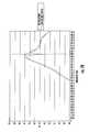
- FIG. 4Ais a plot of simulated free space input return loss for exemplary antenna configurations according to the present invention: including (i) a loop resonator structure disposed proximate to the H-field maximum; (ii) a loop resonator structure disposed proximate to the PWB center point; and (iii) a base PWB configuration without loop resonators.
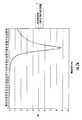
- FIG. 4Bis a plot of simulated broadband E-field at the earpiece location for different antenna configurations according to the invention, including: (i) a loop resonator structure disposed proximate to the H-field maximum; (ii) a loop resonator structure disposed proximate to PWB center point; and (iii) a base PWB configuration without loop resonators.
- FIG. 4Cis a free-space simulated efficiency plot for different antenna configurations according to the invention, including: (i) a loop resonator structure disposed proximate to the H-field maximum; (ii) a loop resonator structure disposed proximate to the PWB center point; and (iii) a base PWB configuration without loop resonators.
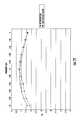
- FIG. 5Ais a plot of measured broadband E-field at the earpiece location for different antenna configurations according to the invention, including: (i) a loop resonator structure disposed proximate to PWB side at center point; and (ii) a base PWB configuration without loop resonators.
- FIG. 5Bis a free-space measured efficiency plot for different antenna configurations according to the invention, including: (i) a loop resonator structure disposed proximate to the PWB side at a central point; and (ii) a base PWB configuration without loop resonators.
- FIG. 6Ais a top plan view illustrating the back side of an exemplary embodiment of a mobile device PWB configuration according to the invention, with an on-ground antenna disposed proximate the top side of the PWB.
- FIG. 7Ais a plot of simulated free space input return loss for the exemplary antenna device of FIG. 6 for: (i) an antenna with the loop resonator structure disposed proximate to the PWB top side; and (ii) a base PWB configuration without loop resonators.
- FIG. 7Bis a plot of simulated broadband E-field at the interference-sensitive component (e.g., earpiece) location for the antenna according to FIG. 6 , including: (i) an antenna with the loop resonator structure disposed proximate to the PWB top side; and (ii) a base PWB configuration without loop resonators.
- the interference-sensitive componente.g., earpiece
- FIG. 7Ca plot of simulated free space antenna efficiency PWB configuration of FIG. 6A for: (i) an antenna with the loop resonator structure disposed proximate to the PWB top side; and (ii) base PWB configuration without loop resonators.
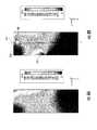
- FIG. 8Adisplays electric E-field simulations for a reference PWB configuration of FIG. 6A with antenna elements disposed proximate to the earpiece.
- FIG. 8Billustrates simulated electric E-field alterations using a loop resonator structure in accordance with the principles of the present invention.
- FIG. 9Aillustrates an exemplary embodiment of a mobile device PWB configuration with an on-ground high-band antenna disposed on an opposite PWB end from the earpiece, and a pair of loop resonators disposed proximate to H-field local maxima, in accordance with the principles of the present invention.
- FIG. 9Billustrates an exemplary embodiment of a mobile device PWB configuration with an on-ground high-band antenna disposed proximate the earpiece, and a pair of loop resonators disposed proximate to H-field local maxima, in accordance with the principles of the present invention.
- FIG. 10presents electric E-field simulations for the PWB of FIG. 9 , comprising a pair of loop resonators disposed proximate to H-field local maxima.
- FIG. 11depicts simulated axial E-field distribution for the PWB configuration of FIG. 10 .
- FIG. 12Bis a free-space efficiency measured with two different antenna configurations including: (i) a loop resonator structure disposed proximate to a PWB side at center point; and (ii) a base PWB configuration without loop resonators.
- a substraterefer generally and without limitation to any substantially planar or curved surface or component upon which other components can be disposed.
- a substratemay comprise a single or multi-layered printed circuit board (e.g., FR4), a semi-conductive die or wafer, or even a surface of a housing or other device component, and may be substantially rigid or alternatively at least somewhat flexible.
- the terms “radiator,” “radiating plane,” and “radiating element”refer without limitation to an element that can function as part of a system that receives and/or transmits radio-frequency electromagnetic radiation; e.g., an antenna.
- feedrefers without limitation to any energy conductor and coupling element(s) that can transfer energy, transform impedance, enhance performance characteristics, and conform impedance properties between an incoming/outgoing RF energy signals to that of one or more connective elements, such as for example a radiator.
- the terms “antenna,” “antenna system,” and “multi-band antenna”refer without limitation to any system that incorporates a single element, multiple elements, or one or more arrays of elements that receive/transmit and/or propagate one or more frequency bands of electromagnetic radiation.
- the radiationmay be of numerous types, e.g., microwave, millimeter wave, radio frequency, digital modulated, analog, analog/digital encoded, digitally encoded millimeter wave energy, or the like.
- the energymay be transmitted from location to another location, using, or more repeater links, and one or more locations may be mobile, stationary, or fixed to a location on earth such as a base station.
- communication systemsand communication devices refer to without limitation any services, methods, or devices that utilize wireless technology to communicate information, data, media, codes, encoded data, or the like from one location to another location.
- frequency rangerefers to without limitation any frequency range for communicating signals. Such signals may be communicated pursuant to one or more standards or wireless air interfaces
- the terms “electrical component” and “electronic component”are used interchangeably and refer to components adapted to provide some electrical function, including without limitation inductive reactors (“choke coils”), transformers, filters, gapped core toroids, inductors, capacitors, resistors, operational amplifiers, and diodes, whether discrete components or integrated circuits, whether alone or in combination.
- inductive reactors(“choke coils”), transformers, filters, gapped core toroids, inductors, capacitors, resistors, operational amplifiers, and diodes, whether discrete components or integrated circuits, whether alone or in combination.
- integrated circuitrefers to any type of device having any level of integration (including without limitation ULSI, VLSI, and LSI) and irrespective of process or base materials (including, without limitation Si, SiGe, CMOS and GaAs).
- ICsmay include, for example, memory devices (e.g., DRAM, SRAM, DDRAM, EEPROM/Flash, ROM), digital processors, SoC devices, FPGAs, ASICs, ADCs, DACs, transceivers, memory controllers, and other devices, as well as any combinations thereof.
- memoryincludes any type of integrated circuit or other storage device adapted for storing digital data including, without limitation, ROM. PROM, EEPROM, DRAM, SDRAM, DDR/2 SDRAM, EDO/FPMS, RLDRAM, SRAM, “flash” memory (e.g., NAND/NOR), and PSRAM.
- microprocessorand “digital processor” are meant generally to include all types of digital processing devices including, without limitation, digital signal processors (DSPs), reduced instruction set computers (RISC), general-purpose (CISC) processors, microprocessors, gate arrays (e.g., FPGAs), PLDs, reconfigurable compute fabrics (RCFs), array processors, and application-specific integrated circuits (ASICs).
- DSPsdigital signal processors
- RISCreduced instruction set computers
- CISCgeneral-purpose
- microprocessorse.g., FPGAs), PLDs, reconfigurable compute fabrics (RCFs), array processors, and application-specific integrated circuits (ASICs).
- FPGAsfield-programmable gate arrays
- RCFsreconfigurable compute fabrics
- ASICsapplication-specific integrated circuits
- the terms “mobile device”, “client device”, “peripheral device” and “end user device”include, but are not limited to, personal computers (PCs) and minicomputers, whether desktop, laptop, or otherwise, set-top boxes, personal digital assistants (PDAs), handheld computers, personal communicators, J2ME equipped devices, cellular telephones, smartphones, personal integrated communication or entertainment devices, or literally any other device capable of interchanging data with a network or another device.
- PCspersonal computers
- PDAspersonal digital assistants
- handheld computerspersonal communicators
- J2ME equipped devicesJ2ME equipped devices
- cellular telephonessmartphones
- smartphonespersonal integrated communication or entertainment devices
- hearing aidrefers without limitation to a device that aids a person's hearings, for example, devices that condition or modify sounds (e.g., amplify, attenuate, and/or filter), as well as devices that deliver sound to a specific person such as headsets for portable music players or radios.
- signal conditioningshall be understood to include, but not be limited to, signal voltage transformation, filtering and noise mitigation, signal splitting, impedance control and correction, current limiting, capacitance control, and/or time delay.
- topAs used herein, the terms “top”, “bottom”, “side”, “up”, “down” and the like merely connote a relative position or geometry of one component to another, and in no way connote an absolute frame of reference or any required orientation. For example, a “top” portion of a component may actually reside below a “bottom” portion when the component is mounted to another device (e.g., to the underside of a PCB).
- wirelessmeans any wireless signal, data, communication, or other interface including without limitation Wi-Fi, Bluetooth, 3G (e.g., 3GPP, 3GPP2, and UMTS), HSDPA/HSUPA, TDMA, CDMA (e.g., IS-95A, WCDMA, etc.), FHSS, DSSS, GSM, PAN/802.15, WiMAX (802.16), 802.20, narrowband/FDMA, OFDM, PCS/DCS, Long Term Evolution (LTE) or LTE-Advanced (LTE-A), analog cellular, CDPD, satellite systems, millimeter wave or microwave systems, optical, acoustic, and infrared (i.e., IrDA).
- 3Ge.g., 3GPP, 3GPP2, and UMTS
- HSDPA/HSUPAe.g., TDMA
- CDMAe.g., IS-95A, WCDMA, etc.
- FHSSDSSS
- GSMG
- the present inventionprovides, in one salient aspect, an antenna apparatus and mobile radio device with improved hearing aid compliance, and methods for manufacturing and utilizing the same.
- the mobile radio devicecomprises a printed wired board (PWB) with a monopole antenna and an ear piece disposed on substantially opposing ends of the PWB.
- a loop resonatoris formed on the PWB ground plane.
- the loop resonatoris constructed so as to form a conductor-free area on the PWB and a gap in the PWB ground plane proximate to the edge of the PWB.
- the loop resonatorforms an LC resonator structure where the capacitance is determined by the loop perimeter, and the inductance is determined by the PWB gap opening.
- the resonator dimensionsare chosen so as to achieve sufficient inductance required for proper coupling to a PWB resonant mode.
- Placement of the loop resonant structure onto the PWBalters the electromagnetic field distribution across the PWB ground plane.
- the PWB electrical lengthis modified so that the PWB has an electric field maximum disposed at a location closer to the antenna, and a minimum disposed at an end that is proximate to the earpiece.
- the electric field strength proximate the earpieceis reduced, therefore advantageously diminishing potential electromagnetic interference with hearing aid devices and hence facilitating hearing aid compliance of the mobile radio device.
- loop resonator placement optionsmay be implemented according to different exemplary embodiments.
- placement of the loop resonator apparatus proximate the location of the magnetic intensity (H) maximum on the PWBproduced the largest electric field reduction at the earpiece location.
- the electric field reductionis not as substantial as compared to the prior embodiment.
- this second embodimentprovides a lower-cost implementation alternative.
- Yet other locationsare also contemplated under the invention.
- the antenna and the earpieceare disposed substantially at the same end of the PWB to allow for a smaller PWB dimensions.
- a pair of loop resonatorsis disposed along the opposing edges of the PWB in order to reduce electric field strength at the earpiece location, thus effecting hearing aid compliance.
- a method for tuning one or more antenna in a mobile radio devicecomprises using one or more loop resonators to shift an E-field local minimum as close to the earpiece location as possible.
- the local E-field minimumis moved proximate to the earpiece location, where HAC is typically measured.
- Fine tuning of the resonator location, dimensions, capacitance and inductanceis further used to set the effective electrical length of the PWB, in order to support high band antenna operation, and increase antenna efficiency bandwidth in small antenna cases. Accordingly, E-field distribution can be made more symmetrical, and provide the opportunity for the E-field “null” to be moved towards a desired location.
- FIGS. 1-12exemplary embodiments of the mobile radio antenna apparatus of the invention are described in detail.
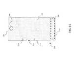
- FIG. 2Aillustrates one embodiment of a mobile radio device PWB in accordance with one embodiment of the present invention.
- the PWB 200comprises a rectangular substrate element with a conductive coating deposited on the front planar face of the substrate element, so as to form a ground plane 102 .
- An antenna 104is disposed proximate to one (horizontal) end 110 of the PWB 200 .
- An earpiece 108(here, a speaker) is located proximate the opposite PWB end 106 away from antenna 104 .
- the PWB size and shapeis bounded by the mechanical outline of the specific mobile device, and determined by other features such as accommodating other device components (e.g., battery, display, etc.).
- a loop resonator structure 210is disposed on the ground plane 202 proximate the vertical side 214 of the PWB 200 .
- the exemplary PWB 200according to one embodiment comprises a rectangular shape of about 110 mm (4.3 in.) in length, and 40 mm (1.6 in.) in width, and the dimensions of the exemplary antenna is are 40 ⁇ 8 mm (1.6 ⁇ 0.2 in.). As persons skilled in the art will appreciate, the dimensions given above may be modified as required by the particular application.
- the loop resonator 210is typically formed by etching a portion of the conductive coating from PWB ground plane 202 .
- the etched portionis substantially a dielectric substrate, and it comprises a rectangle with the longer dimension 218 oriented parallel with the antenna main dipole axis.
- the main axisis oriented vertically, and the loop resonator 210 is placed proximate to the vertical side 214 of the PWB.
- the PWBcomprises a square shaped structure, and the loop resonator is placed proximate either the horizontal or vertical edge of the PWB (provided it is placed effectively parallel with the antenna main dipole-like axis).
- the exemplary loop structure according to the embodiment shown in FIG. 2Bis 9 mm in length and 5 mm in width (roughly 0.3 ⁇ 0.2 in.).
- the loop dimensions 218 and 220are chosen so as to achieve sufficient inductance required for proper coupling to the PWB resonant mode.
- the dimensions of the resonator loop that optimize the electrical current path lengthare determined using a combination of computer modeling and measurements for each antenna configuration. Typically, shorter loop lengths require larger capacitance values. However this combination produces narrower band resonance within the loop. To effectively couple the resonator loop to the ground plane resonance, it is desirable to maximize the loop dimension normal to ground plane edge, while taking into consideration the PWB layout design compactness.
- FIG. 2Cone embodiment of a mobile radio device PWB 240 is shown in detail.
- the back side 240 of the PWBis shown in FIG. 2C , and the loop resonator element further comprises a discrete capacitor 222 .
- the resonator loop 210further comprises a discrete capacitor electrically coupled to the ground plane conductive coating 202 across two sides (e.g. two opposing or two adjacent sides) of the opening 216 .
- the loop 210 shown in FIG. 2Dis made on the PWB ground plane 202 as an etched pattern, while the capacitance for resonating the loop is provided via the dielectric block 222 which has a slot to separate the block ends, and to generate the capacitance.
- This approachadvantageously makes it easier to adjust the capacitance for a desired application, and to obtain more accurate capacitance values for precise resonance tuning.
- the resonant loop structure 210can be formed as a separate element (not shown) with an integrated capacitor and attached to PWB via dedicated additional contact points.
- This separate elementcan be oriented parallel, normal or at an angle to the plane of PWB, while being parallel to the antenna main dipole-like axis, as required by a specific application
- capacitorsmay be used consistent with the present invention.
- various types of capacitorsmay be used, such as discrete (e.g., plastic film, mica, glass, or paper) capacitors, or chip capacitors.
- discretee.g., plastic film, mica, glass, or paper
- chip capacitorse.g., chip capacitors
- loop resonator structurecan be used with a wide variety of configurations, including all quarter-wave antenna types (e.g. PIFA, monopole, etc.) that utilize the ground plane as a part of the radiating structure.
- quarter-wave antenna typese.g. PIFA, monopole, etc.
- Exemplary embodiments of the antenna of the present inventionutilize an LC (inductive-capacitive) resonating circuit.
- LC resonating circuitsare well known in the electrical arts. Specifically, if a charged capacitor is connected across an inductor, electric charge will start to flow through the inductor, generating a magnetic field around it, and reducing the voltage across the capacitor. Eventually, the electric charge of the capacitor will be dissipated. However, the current will continue to flow through the inductor because inductors tend to resist rapid current changes, and energy will be extracted from the magnetic field to keep the current flowing. The current will begin to charge the capacitor with a voltage of opposite polarity to its original charge therefore depleting the magnetic field of the inductor. When the magnetic field is completely dissipated, the current will cease, and the electric charge will again be stored in the capacitor (with the opposite polarity). Then the discharge cycle will begin again, with the current flowing in the opposite direction through the inductor.
- the loop 210forms an LC resonator structure, where the capacitance is determined by the loop perimeter, and the inductance is determined by the size and configuration the PWB opening 216 . Typically, a 1 pF capacitance is sufficient to generate loop resonance.
- a ceramic capacitive block 222is used to achieve more accurate capacitive tuning of the resonator structure 210 if necessary.
- Placement of the loop resonant structure 210 onto PWB 200alters the electromagnetic field distribution across the PWB ground plane.
- the PWB electrical lengthis modified so that PWB has a field maximum at a location closer to antenna, and a second maximum at the top end of the PWB (resonator loops create a high impedance point at the PWB).
- simulated electric (E) and magnetic (H) field distribution across the PWB ground planeare presented for a PWB 200 with the loop resonator structure 210 located proximate to the magnetic field maximum 128 .
- the location of the H-field maximumis computed using simulation results obtained with a bare PWB 100 and described above in FIG. 1B .
- the PWB electric field distribution generated by a uniform PWB ground plane (reference case) shown in FIG. 1Bis similar to a half-wave dipole distribution with E-field maxima located at both ends of the ground plane.
- Simulations performed by the Assignee hereof presented in FIG. 3Acorrespond to an air-filled opening or gap on the ground plane, and loop dimensions described in FIG. 2B . Comparing the E-field distributions of FIG. 3A and FIG. 1B , a noticeable shift in the E-field is observed: the local minimum 304 is moved closer to the top edge 106 of the PWB. Additionally, as a result of placing the loop resonator structure onto the PWB, areas with higher levels of electric field are moved close to the top corner 306 and away from the location of the interference-sensitive component (e.g., earpiece 108 ).
- the interference-sensitive componente.g., earpiece 108
- FIG. 3Bsimulated electric (E) and magnetic (H) field distribution across the PWB ground plane are presented for the PWB 200 with the loop resonator structure located proximate to center point of the PWB long side 214 .
- Simulations performed by the Assignee hereof and presented in FIG. 3Bcorrespond to an air-filled opening or gap on the ground plane, and loop dimensions described in FIG. 2B .
- the E-field shiftis less pronounced in the FIG. 3B configuration, and the E-field null (minimum) 304 is located farther away from the earpiece 108 as when compared to the data displayed in FIG. 3A .
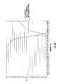
- FIG. 3Ba plot of simulated free space input return loss in decibel (dB) as a function of frequency (in GHz) for the exemplary antenna configurations of the present invention is shown.
- the antenna configurationsinclude: (i) a loop resonator structure disposed proximate to the H-field maximum (ii) a loop resonator structure disposed proximate to PWB side at center point; and (iii) a base PWB configuration without loop resonators. Analyzing FIG. 4A , a second resonance is observed proximate to about 1.88 GHz frequency (center point of the PCS-1900 transmit band) for the PWB configuration comprising the resonant loop located at the H-field maximum.
- FIG. 4Ba plot of simulated broadband electric field level in decibels (dB) computed at the earpiece location 206 as a function of frequency (in GHz) for the exemplary antenna configurations of the present invention is shown.
- the different curves shown in FIG. 4Bcorrespond to the three different configurations discussed above with respect to FIG. 4A as follows: (i) a loop resonator structure disposed proximate to the H-field maximum; (ii) a loop resonator structure disposed proximate to PWB side at center point; and (iii) a base PWB configuration without loop resonators. Analyzing FIG.
- FIG. 4Ca free-space simulated efficiency plot for different antenna configurations is shown, including: (i) a loop resonator structure disposed proximate to the H-field maximum; (ii) a loop resonator structure disposed proximate to PWB center point; and (iii) no loop resonator. Comparing the base PWB configuration with both resonant loop PWB configurations shown in FIG. 4C , it is apparent that the addition of one or more resonant loops to the PWB antenna structure does not reduce the overall antenna efficiency.
- FIGS. 5A-5Cillustrate a series of measurements corresponding to the simulations results of FIG. 4A-FIG . 4 C collected with a prototype PWB antenna apparatus constructed by the Assignee hereof, modified according with the principles of the present invention.
- FIG. 5Ashows a plot of measured broadband E-field at the earpiece location for different antenna configurations, including: (i) a loop resonator structure disposed proximate to the PWB side at center point; and (ii) a base PWB configuration without loop resonators.
- the solid vertical lines of FIG. 5Adenote the PCS transmit frequency band. Comparing E-field measurements for the two PWB configurations presented in FIG.
- an approximately 2-dB reduction of electrical radiated field at the earpiece locationis advantageously produced within the PCS transmit band when a loop resonator structure is placed on the side center of the PWB ground plane according to the present invention. This corresponds to a 60% reduction in the radiated power levels.
- FIG. 5Bdisplays a free-space measured efficiency within a PCS transmit band (also referred to as the “high band”) for different antenna configurations including: (i) a loop resonator structure disposed proximate to the PWB side at center point; and (ii) a base PWB configuration without loop resonators.
- the results of FIG. 5Bare consistent with the data presented above in FIG. 4C , and confirm that the addition of resonant loops to the PWB antenna structure does not reduce the overall antenna efficiency.
- high band efficiencyis not affected since the PWB length is still sufficient to support the antenna resonant mode.
- the effective PWB lengthresonates at the high-band, and therefore improves high-band bandwidth.
- FIG. 6A and FIG. 6Billustrate an exemplary embodiment of a mobile device PWB 600 configuration wherein an on-ground high-band antenna 104 is disposed proximate the top side 106 of the PWB.
- FIG. 6Ais a top plan view of the PWB back side 601 showing the antenna 104 and earpiece 108 disposed on the planar side of the PWB 600 that is opposite from the ground plane 102 side.
- FIG. 6Bshows the PWB front side 602 , earpiece 108 , and radiation reducing resonant loop structure 210 disposed on ground plane 102 along a vertical side 214 proximate to the PWB mid-point shown in FIG. 6A .
- FIG. 7Ais a plot of simulated free space input return loss in decibel (dB) as a function of frequency (in GHz).
- the corresponding base PWB configuration simulations(computed without the loop resonator) are also shown in FIG. 7A . Comparing the two results presented in FIG. 7A , a very close agreement between the two simulations results is observed.
- FIG. 7Billustrates the simulated broadband electric field level in decibel (dB) computed at the earpiece location 610 as a function of frequency (in GHz.
- the different curves in FIG. 7Bcorrespond to the three different configurations discussed above with respect to FIG. 7A as follows: (i) a loop resonator structure disposed proximate to PWB side at center point; and (ii) a base PWB configuration without loop resonators. Comparing the two results presented in FIG. 7B , a substantial reduction of the electric field level (of about 3.5 dB) is observed proximate to a frequency of about 1.88 GHz for the resonant loop configuration. It is apparent from the results shown in FIG. 7B that placing a resonant loop structure onto the PWB substantially reduces the electric field as compared to the loop base BWB configuration results.
- FIG. 7Cfree-space simulated total efficiency plots for different antenna configurations discussed above with respect to FIG. 7B are shown.
- the different curves in FIG. 7Ccorrespond to (i) a loop resonator structure disposed proximate to PWB side at center point; and (ii) a base PWB configuration without loop resonators. Comparing the base PWB configuration with the resonant loop PWB configuration shown in FIG. 7C , it is apparent that the addition of one or more resonant loops to the PWB antenna structure does not reduce the overall antenna efficiency. High band efficiency is advantageously not affected, since PWB length is still sufficient to support the requisite antenna resonant mode. By placing the loop at the H-field maximum location, the PWB length resonates at the high-band, and therefore improves high-band bandwidth.
- FIG. 8Ashows a simulated electric (E) field (V/m) distribution across the PWB ground plane of the PWB configuration of FIG. 6A discussed above, without the resonant loop structure. Comparing the E-field data shown in FIG. 8A (the antenna element 102 disposed proximate to the location of the earpiece 606 ) with the E-field data presented above in FIG. 3A (antenna element 103 disposed on the opposite end from the location of the earpiece 108 ), it is apparent that the electric field levels proximate the earpiece location 108 are higher (as shown in FIG. 8A ) when the antenna element 104 is located proximate to the earpiece 108 as in the PWB configuration of FIG. 6A .
- Eelectric
- FIG. 8Bshows a simulated electric (E) field distribution across the PWB ground plane 102 for the PWB structure of FIG. 6B (with a loop resonator structure 210 located proximate center point of PWB 602 long side 214 ).
- Simulations performed by the Assignee hereof and presented in FIG. 813corresponds to an air-filled opening or gap on the ground plane, and loop resonator dimensions as described in FIG. 2B .
- alternate resonant loop configurationsmay be used consistent with the present invention such as, inter alia, the examples presented in FIG. 2C and FIG. 2D , or variations thereof.
- the shifts of local maxima and minimaare less pronounced than in the data presented above in FIG. 3A .
- the null area 810is noticeably asymmetric, and located closer to the left top corner area 812 . Therefore when the antenna element and E-field point of interest (e.g., earpiece) are on same end of the PWB (with respect to the vertical dimension of FIG. 6A ), a single loop resonator may not be sufficient to modify the electric field distribution enough to reduce the electric field level in the proximity of the earpiece.
- additional loop resonator(s)are required to make electric field distribution fields more symmetric, and to shift the “null” area towards the center axis 814 of the PWB.
- a pair of resonators placed on the opposing vertical sides of the PWB ground planebrings the null center 810 closer to the PWB vertical center axis 814 , and consequently closer to the earpiece 108 location. It will be appreciated, however, that other combinations of resonators (and their locations) may be used consistent with the invention in order to dispose the null at the desired location, and/or create multiple smaller relative nulls at two or more locations on the PCB.
- the PWB 900 of FIG. 9Acomprises a substantially rectangular substrate element with a conductive coating deposited on the top planar side of the substrate to form a ground plane 102 .
- An antenna element 104is placed proximate the PWB bottom edge 110 on the planar side that is opposite from the conductive coating side.
- An audio componente.g., earpiece 108
- a plurality of loop resonator structures 210are further disposed on the ground pane 102 along vertical side edges of the PWB 900 .
- each resonator structure 210is formed according to the principles of the invention as illustrated above at FIG. 2B or FIG. 2D , although it is further appreciated that the resonator structures may be heterogeneous in nature; e.g., one of a first type, size, and/or configuration, and one of a second type, size and/or configuration.
- the resonator structures 210are placed proximate locations of H-field maxima 126 , 128 .
- the determination of the H-field maximais performed using H-field simulations of a PWB without loop resonators, as discussed above in reference to FIG. 1C .
- FIG. 9Bdescribes an alternative PWB embodiment comprising a pair of loop resonators.
- the PWB 920 configuration of FIG. 9Bis in many ways similar to the PWB configuration 900 described above. However, in this case, the antenna element 104 is placed proximate the PWB top edge 106 on the planar side that is opposite from the conductive coating side. This PWB configuration places the antenna element 104 proximate to the audio component 108 , thus enabling reduction of the PWB lateral (longer) dimension.
- the resonator structures 210are placed proximate to the locations of H-field maxima 126 , 128 .
- the determination of the H-field maximais performed using H-field simulations of a PWB without loop resonators, as discussed above in reference to FIG. 1C .
- Each resonator structure 210is configured such as that illustrated above at FIG. 2B or FIG. 2D , although it is further appreciated that the resonator structures may be heterogeneous in nature; e.g., one of a first type, size, and/or configuration, and one of a second type, size and/or configuration.
- FIG. 10a simulated electric (E) field distribution across the ground plane is presented for the PWB configuration 900 of FIG. 9 .
- the two loop resonatorsare 210 are disposed proximate to the magnetic field local maxima.
- the simulations presented in FIG. 10correspond to an air-filled opening or gap on the ground plane, and loop dimensions as described in FIG. 2B . Comparing the E-field distributions of FIG. 10 and FIG. 3A , noticeable changes in the E-field distribution are observed: i.e., the local minimum (null) 304 is moved closer to the top edge 106 of the PWB.
- Placing loop resonators at the PWB edgesmodifies the PWB electrical length so that electric field maxima are formed at a location closer to the antenna, and near the top edge (the resonator loops create a high impedance point) of the PWB.
- loop resonatorsWhen the antenna element and E-field point of interest (audio component) are on same end of the ground plane, use of loop resonators to modify the field distribution is not as effective, as in case where antenna is placed to the opposite end of the PWB. In this case, a second (or yet additional) resonator should be added so that the resonators are placed on both sides of the ground plane to bring the null to the center of the PWB x-axis.
- points of interestmay exist (such as where two or more electrically sensitive components are disposed on the PWB at different locations).
- various component/device configurationscan be used to achieve acceptable results at each of the points of interest, versus perhaps optimizing the performance at one point of interest to the detriment of one or more other points of interest.
- the present inventioncontemplates a “holistic” tuning approach, wherein multiple points are considered simultaneously, and more modest improvements in field reduction at multiple such points are traded for a more significant reduction at one point, and lesser reductions at other points (“balanced” approach).
- the methodcomprises using one or more loop resonators to shift the E-field local minimum as close to the earpiece location as possible.
- the local E-field minimumis moved proximate to the earpiece location (where HAC is typically measured).
- Fine-tuning of the resonator locationis further used to “set” the effective electrical length of the PWB to support high-band antenna operation, and increase antenna efficiency bandwidth in small antenna cases.
- one or more additional loop resonatorsenable making the E-field distribution more symmetric, and moving the E-field null(s) towards a (or respective) desired location(s).
- FIG. 11a simulated axial E-field distribution is shown along axis 814 (as described above with respect to FIG. 8B ) with the antenna element 104 placed proximate the bottom edge of the PWB 900 and opposite from the earpiece location ( FIG. 10 ).
- FIG. 11shows the base PWB configuration without loop resonators, as well as data from simulations performed for the PWB configuration comprising a pair of loop resonators 210 as shown above in FIG. 9A .
- FIG. 11a reference case with uniform PWB ground plane electric field distribution is shown, similar to a half-wave dipole distribution with an E-field maxima at the ground plane horizontal edges 106 , 110 .
- the loop resonators placed on the PWB vertical edgesmodify the electric field distribution so that the PWB has a field maximum at a location closer to the antenna 104 , and a minimum proximate to the PWB top edge 106 (the resonator loops create a high impedance point to the PWB).
- antenna tuningmay be performed by varying the capacitance or inductance (or both) values of the LC resonator.
- FIG. 12A and FIG. 12Bone embodiment of the method of antenna tuning using loop resonator structure(s) in accordance with the principles of the present invention is described and illustrated.
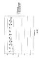
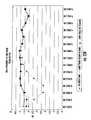
- FIG. 12Ashows the electric field strength in dB measured at the PWB earpiece location 108 for the following PWB configurations: (i) the base PWB configuration without loop resonator tuning; (ii) PWB with the resonator loop(s), placed proximate to the center point of the PWB long side 214 , and tuned below the antenna transmit band of operation; and (iii) PWB with the resonant loop(s), placed proximate center point of the PWB long side 214 , and tuned to the antenna band of operation.
- the vertical lines in FIG. 12Amark the boundaries of GSM-850 transmit (TX) frequency band, which is selected purely for purposes of illustration. Consistent with the Eqn.
- the capacitor value corresponding to the loop tuned on GSM-850 transmit band(shown in FIG. 12A ) is smaller than the capacitance value used to tune resonant loop below GSM-850 TX band.
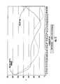
- FIG. 12Billustrates the measured total free-space antenna efficiency in dB over the GSM-850 TX frequency band for the following PWB configurations: (i) the base PWB configuration without loop resonator tuning; (ii) resonant loop(s) placed proximate to the center point of the PWB long side 214 and tuned below the antenna transmit band of operation; and (iii) resonant loop(s) placed proximate to the center point of the PWB long side 214 and tuned to the antenna band of operation.
- FIG. 12Billustrates the measured total free-space antenna efficiency in dB over the GSM-850 TX frequency band for the following PWB configurations: (i) the base PWB configuration without loop resonator tuning; (ii) resonant loop(s) placed proximate to the center point of the PWB long side 214 and tuned below the antenna transmit band of operation; and (iii) resonant loop(s) placed proximate to the center point
- the HAC compliance methodology of the present embodimentis more effective when operating in the high band frequency range (e.g. 1800 MHZ or 1900 MHz) where antenna efficiency is typically less dependent on PWB length.
- benefitsare none-the-less provided in lower frequency bands (albeit not quite as large as those in the higher bands).
- the 802.11) interfacetypically operates at roughly 2.4 GHz, and can also create electric field interference with sensitive devices such as earpieces.
- the present inventionexplicitly recognizes that the techniques described supra may be applied to the antenna(s) associated with these auxiliary (e.g., PAN/WLAN/WMAN) interfaces, so as to mitigate or shift the field strength at the desired location(s).
- the field created by the PAN/WLAN/WMAN interfacemay also be additive with that created by the cellular interface(s), such as where the cellular interface is being used simultaneously with the WLAN interface (e.g., the user is talking on the phone and also sending packetized data over the WLAN interface).
- the present inventionfurther contemplates “complex” application, modeling and design scenarios, such that two or more interfaces are considered in the design and/or compensation process (e.g., loop resonators may be used on the antenna of both interfaces if separate, such that the additive fields from both antennas are mitigated sufficiently to produce HAC compliance or other desired objectives).
- loop resonatorsmay be used on the antenna of both interfaces if separate, such that the additive fields from both antennas are mitigated sufficiently to produce HAC compliance or other desired objectives.
- several separate loop resonatorsare each tuned to the corresponding radio frequency band, and are located so as to achieve the best coupling to the PWB ground plane, and to accomplish the greatest electric field reduction at a point(s) of interest.
Landscapes
- Support Of Aerials (AREA)
Abstract
Description
A portion of the disclosure of this patent document contains material that is subject to copyright protection. The copyright owner has no objection to the facsimile reproduction by anyone of the patent document or the patent disclosure, as it appears in the Patent and Trademark Office patent files or records, but otherwise reserves all copyright rights whatsoever.
The present invention relates generally to internal antennas for use in portable radio devices and more particularly in one exemplary aspect to a passive loop resonator structure to control antenna ground plane field distribution in order to improve hearing aid compliance, and methods of utilizing and manufacturing the same.
Internal antennas are an element found in most modern portable radio devices, such as mobile phones, Blackberry® devices, smartphones, personal digital assistants (PDAs), or other personal communication devices (PCD). Typically, these antennas comprise a planar radiating plane and a ground plane parallel thereto, which are connected to each other by a short-circuit conductor in order to achieve the matching of the antenna. The structure is dimensioned so that it functions as a resonator at the operating frequency. It is a common requirement that the antenna operate in more than one frequency band (such as dual band, tri-band, or quad-band mobile phones) in which case two or more resonators are used.
Typically, internal antennas are constructed to comprise at least a part of a printed wired board (PWB) assembly, also commonly referred to as the printed circuit board (PCB).FIG. 1A shows a typical configuration of thePWB 100 in a mobile radio device. The PWB100 comprises aground plane 102,monopole antenna 104 disposed proximate to oneend 110 of the PWB (on the opposite side from ground plane102), and an earpiece108 (speaker) located a distance from the antenna104 (e.g., on the opposite end from the antenna). Such configuration is typically chosen to optimize mobile phone packaging volume, and/or to minimize interference between the antennaactive element 104 andearpiece 108.
For example, the Hearing Aid Compatibility Act of 1988 (HAC Act) mandated that all telephones made or imported into the United States be compatible with hearing aids, but specifically exempted mobile telephones. In July 2003, the Federal Communications Commission FCC modified the HAC Act's exemption for mobile phones, mandating that manufacturers provide certain numbers of models or percentages of mobile phones that are hearing aid compatible HAC by 2005 and 2008.
Increased electric field energy in the vicinity of the earpiece results in high field values in the hearing aid compliance measurement. Numerous methodologies exist for reducing electrical interference and improving hearing aid compliance in mobile radio devices, including for example, those disclosed in U.S. Pat. No. 6,009,311 to Killion, et al. issued Dec. 28, 1999, and entitled “Method and apparatus for reducing audio interference from cellular telephone transmissions”; United States Patent Pub. No. 2009/0243944 to Jung, et al. published Oct. 1, 2001, and entitled “Portable Terminal”; United States Patent Pub No. 2009/0219214 to Oh published Sep. 3, 2009 and entitled “Wireless handset with improved hearing aid compatibility”; U.S. Pat. No. 5,442,280 to Johnson, issued Oct. 28, 2003 and entitled “Device and method of use for reducing hearing aid RF interference”, each of the foregoing being incorporated herein by reference in its entirety. However, exiting approaches require additional energy absorbing elements, electric field reducing units, external field shaping conductors, and/or signal processing methods that add cost and complexity.
The prior art commonly addresses the HAC requirements for mobile phones by implementing monopole grounded resonator strips on bothends PWB 100 in order to change the electric field distribution. This approach inherently has drawbacks, such as increased PWB size, and makes mechanical implementation difficult. For instance, in the low band, the antenna becomes more sensitive to dielectric loading from mechanics and user body parts, and additional contacts between the PWB ground plane and the device mechanics are required.
Therefore, there is a salient need for apparatus and methods for altering radio antenna ground field distribution in mobile radio devices so as to reduce electric field interference, and improve hearing aid compliance for mobile phones and other mobile radio devices.
The present invention satisfies the foregoing needs by providing, inter alia, a loop resonator structure and associated methods which alter antenna ground plane field distribution.
In a first aspect of the invention, an antenna assembly for use in a mobile wireless device is disclosed. In one embodiment, said antenna comprises: a dielectric element having a longitudinal direction and a transverse direction and first and second substantially planar sides; a conductive coating deposited on the first substantially planar side forming a ground plane; a radiating element disposed on the second substantially planar side; an audio component disposed at least partly on the first planar side; and a resonant element having a longitudinal dimension and a transverse dimension and formed at least partially on said ground plane proximate to one longitudinal side of said dielectric element, said resonant element further comprising a first portion and a second portion. The conductive coating is removed from beneath said first and second portions thus forming an opening on said one longitudinal side, and a resonance is formed substantially between the first portion and the second portion.
In one variant, the assembly further comprises a capacitive element electrically coupled to said ground plane between a first side and a second side of said opening.
In another variant, said resonant element comprises a resonance having a center frequency of approximately 1880 MHz. In yet another variant, said resonant element comprises a resonance having a center frequency below 900 MHz.
In a further variant, said audio component comprises a speaker.
In a second aspect of the invention, a method of tuning an antenna for use in a mobile device is disclosed. In one embodiment, the mobile device further comprise an audio component, and said method comprises: disposing at least one resonator element onto a ground plane of said antenna, said element comprising at least a capacitance and an inductance; selecting said capacitance to create a electric resonance at a first frequency, and adjusting location of said resonator element on said ground plane to optimize an electric field distribution across said ground plane. The optimization of said electric field distribution comprises reducing an electric field strength at a location proximate to said audio component.
In one variant, said audio component comprises a speaker, and said tuning comprises tuning so that said antenna is compliant with at least one hearing aid compatibility standard or requirement (e.g., the Hearing Aid Compatibility Act of 1988 (HAC Act) as amended in 2003).
In another variant, the electric resonance is formed between said capacitance and said inductance.
In a third aspect of the invention, a method of altering the electric field distribution across a ground plane of a mobile device antenna is disclosed. In one embodiment, said method comprises: disposing a resonator element onto antenna ground plane, said resonator element comprising at least a capacitance and inductance; selecting said capacitance to form a resonance at a first frequency; and adjusting a location of said resonator element on said ground plane to optimize and electric field distribution across said ground plane.
In one variant, said mobile device further comprises an electrically sensitive component disposed proximate said ground plane, and said act of adjusting a location comprises adjusting said location so that an electric field strength is minimized substantially coincident with a location of said electrically sensitive component. The electrically sensitive component comprises an audio speaker, and said act of adjusting a location enables said mobile device to be compliant with a hearing aid audio-related requirement.
In a fourth aspect of the invention, a method of enabling hearing aid compliance is disclosed. In one embodiment, the method is adapted for use in a mobile radio device comprising a ground plane, an antenna and an audio component, and comprises: providing at least one resonator element for use on a ground plane of said antenna, said at least one resonator element comprising at least a capacitance and an inductance, said capacitance configured to form a resonance at a first frequency; and disposing said at least one resonator element on said ground plane at a location selected to reduce electric field strength proximate to said audio component location, thereby reducing interference of said antenna with said audio component and effecting said hearing aid compliance.
In a fifth aspect of the invention, an antenna for use in a mobile radio device is disclosed. In one embodiment, the antenna comprises: a ground plane; and at least one resonator element disposed on said ground plane of said antenna, said at least one resonator element comprising at least a capacitance and an inductance and configured to form a resonance at a first frequency. The at least one resonator element is disposed on said ground plane at a selected first location so as to reduce electric field strength at a second location.
In one variant, said mobile radio device comprises an interference-sensitive component, and said second location is proximate to a location of said interference-sensitive component, said reduced electrical field strength thereby reducing interference of said antenna with said interference-sensitive component.
In another variant, the interference-sensitive component comprises an audio component.
In yet another variant, said interference-sensitive component comprises an electric coil component.
In still a further variant, said at least one resonator element comprises a loop-type shape having at least one gap formed therein. The at least one gap comprises e.g., a single gap formed proximate a longitudinal edge of a substrate onto which said ground plane is formed.
In a sixth aspect of the invention, a method of operating an antenna within a mobile device is disclosed. In one embodiment, the method comprises: receiving an antenna input signal from an electronic component of said mobile device; and creating a resonance within a resonator element of said antenna based at least in part on said input signal and a capacitance of said resonator element, said capacitance at least in part causing an electric field generated by way of said resonance to be mitigated in a desired location on said antenna while still emitting a desired radio frequency signal from said antenna.
In a seventh aspect of the invention, a method of designing a mobile device antenna is disclosed. In one embodiment, the method is adapted for design of a HAC-compliant antenna, and comprises selecting a readily identifiable location for one or more resonators on a PWB, and disposing the one or more resonators at that location on the PWB so as to suppress electric field strength at another desired location on the PWB. This process obviates the need for computerized simulation of E- and H-fields for the device.
In an eighth aspect of the invention, a mobile device is disclosed. In one embodiment, the mobile device is adapted to radiate wireless signals via a substantially planar form factor antenna having a resonator, which mitigates at least one electric field intensity level at a desired location within the mobile device, so as to mitigate interference with interference-sensitive components such as audio earpieces. In one variant, the mobile device comprises a cellular telephone or smartphone adapted to radiate at approximately 1900 MHz.
These and other embodiments, aspects, advantages, and features of the present invention will be set forth in part in the description which follows, and in part will become apparent to those skilled in the art by reference to the following description of the invention and referenced drawings or by practice of the invention.
The features, objectives, and advantages of the invention will become more apparent from the detailed description set forth below when taken in conjunction with the drawings, wherein:
All Figures disclosed herein are © Copyright 2009 Pulse Engineering, Inc. All rights reserved.
Reference is now made to the drawings wherein like numerals refer to like parts throughout.
As used herein, the terms “board” and “substrate” refer generally and without limitation to any substantially planar or curved surface or component upon which other components can be disposed. For example, a substrate may comprise a single or multi-layered printed circuit board (e.g., FR4), a semi-conductive die or wafer, or even a surface of a housing or other device component, and may be substantially rigid or alternatively at least somewhat flexible.
As used herein, the terms “radiator,” “radiating plane,” and “radiating element” refer without limitation to an element that can function as part of a system that receives and/or transmits radio-frequency electromagnetic radiation; e.g., an antenna.
The terms “feed,” “RF feed,” “feed conductor,” and “feed network” refer without limitation to any energy conductor and coupling element(s) that can transfer energy, transform impedance, enhance performance characteristics, and conform impedance properties between an incoming/outgoing RF energy signals to that of one or more connective elements, such as for example a radiator.
Furthermore, the terms “antenna,” “antenna system,” and “multi-band antenna” refer without limitation to any system that incorporates a single element, multiple elements, or one or more arrays of elements that receive/transmit and/or propagate one or more frequency bands of electromagnetic radiation. The radiation may be of numerous types, e.g., microwave, millimeter wave, radio frequency, digital modulated, analog, analog/digital encoded, digitally encoded millimeter wave energy, or the like. The energy may be transmitted from location to another location, using, or more repeater links, and one or more locations may be mobile, stationary, or fixed to a location on earth such as a base station.
The terms “communication systems” and communication devices” refer to without limitation any services, methods, or devices that utilize wireless technology to communicate information, data, media, codes, encoded data, or the like from one location to another location.
The terms “frequency range”, “frequency band”, and “frequency domain” refer to without limitation any frequency range for communicating signals. Such signals may be communicated pursuant to one or more standards or wireless air interfaces
As used herein, the terms “electrical component” and “electronic component” are used interchangeably and refer to components adapted to provide some electrical function, including without limitation inductive reactors (“choke coils”), transformers, filters, gapped core toroids, inductors, capacitors, resistors, operational amplifiers, and diodes, whether discrete components or integrated circuits, whether alone or in combination.
As used herein, the term “integrated circuit” or “IC)” refers to any type of device having any level of integration (including without limitation ULSI, VLSI, and LSI) and irrespective of process or base materials (including, without limitation Si, SiGe, CMOS and GaAs). ICs may include, for example, memory devices (e.g., DRAM, SRAM, DDRAM, EEPROM/Flash, ROM), digital processors, SoC devices, FPGAs, ASICs, ADCs, DACs, transceivers, memory controllers, and other devices, as well as any combinations thereof.
As used herein, the term “memory” includes any type of integrated circuit or other storage device adapted for storing digital data including, without limitation, ROM. PROM, EEPROM, DRAM, SDRAM, DDR/2 SDRAM, EDO/FPMS, RLDRAM, SRAM, “flash” memory (e.g., NAND/NOR), and PSRAM.
As used herein, the terms “microprocessor” and “digital processor” are meant generally to include all types of digital processing devices including, without limitation, digital signal processors (DSPs), reduced instruction set computers (RISC), general-purpose (CISC) processors, microprocessors, gate arrays (e.g., FPGAs), PLDs, reconfigurable compute fabrics (RCFs), array processors, and application-specific integrated circuits (ASICs). Such digital processors may be contained on a single unitary IC die, or distributed across multiple components.
As used herein, the terms “mobile device”, “client device”, “peripheral device” and “end user device” include, but are not limited to, personal computers (PCs) and minicomputers, whether desktop, laptop, or otherwise, set-top boxes, personal digital assistants (PDAs), handheld computers, personal communicators, J2ME equipped devices, cellular telephones, smartphones, personal integrated communication or entertainment devices, or literally any other device capable of interchanging data with a network or another device.
As used herein, the term “hearing aid” refers without limitation to a device that aids a person's hearings, for example, devices that condition or modify sounds (e.g., amplify, attenuate, and/or filter), as well as devices that deliver sound to a specific person such as headsets for portable music players or radios.
As used herein, the term “signal conditioning” or “conditioning” shall be understood to include, but not be limited to, signal voltage transformation, filtering and noise mitigation, signal splitting, impedance control and correction, current limiting, capacitance control, and/or time delay.
As used herein, the terms “top”, “bottom”, “side”, “up”, “down” and the like merely connote a relative position or geometry of one component to another, and in no way connote an absolute frame of reference or any required orientation. For example, a “top” portion of a component may actually reside below a “bottom” portion when the component is mounted to another device (e.g., to the underside of a PCB).
As used herein, the term “wireless” means any wireless signal, data, communication, or other interface including without limitation Wi-Fi, Bluetooth, 3G (e.g., 3GPP, 3GPP2, and UMTS), HSDPA/HSUPA, TDMA, CDMA (e.g., IS-95A, WCDMA, etc.), FHSS, DSSS, GSM, PAN/802.15, WiMAX (802.16), 802.20, narrowband/FDMA, OFDM, PCS/DCS, Long Term Evolution (LTE) or LTE-Advanced (LTE-A), analog cellular, CDPD, satellite systems, millimeter wave or microwave systems, optical, acoustic, and infrared (i.e., IrDA).
Overview
The present invention provides, in one salient aspect, an antenna apparatus and mobile radio device with improved hearing aid compliance, and methods for manufacturing and utilizing the same. In one embodiment, the mobile radio device comprises a printed wired board (PWB) with a monopole antenna and an ear piece disposed on substantially opposing ends of the PWB. A loop resonator is formed on the PWB ground plane. The loop resonator is constructed so as to form a conductor-free area on the PWB and a gap in the PWB ground plane proximate to the edge of the PWB. The loop resonator forms an LC resonator structure where the capacitance is determined by the loop perimeter, and the inductance is determined by the PWB gap opening. The resonator dimensions are chosen so as to achieve sufficient inductance required for proper coupling to a PWB resonant mode.
Placement of the loop resonant structure onto the PWB alters the electromagnetic field distribution across the PWB ground plane. By placing the loop resonator apparatus on the PWB edge(s), the PWB electrical length is modified so that the PWB has an electric field maximum disposed at a location closer to the antenna, and a minimum disposed at an end that is proximate to the earpiece. The electric field strength proximate the earpiece is reduced, therefore advantageously diminishing potential electromagnetic interference with hearing aid devices and hence facilitating hearing aid compliance of the mobile radio device.
Different loop resonator placement options may be implemented according to different exemplary embodiments. In a first embodiment, placement of the loop resonator apparatus proximate the location of the magnetic intensity (H) maximum on the PWB produced the largest electric field reduction at the earpiece location. In a second embodiment, when the loop resonator apparatus is installed substantially at the midpoint of the PWB, the electric field reduction is not as substantial as compared to the prior embodiment. However, as the determination of the mid-point location is typically more straightforward, this second embodiment provides a lower-cost implementation alternative. Yet other locations are also contemplated under the invention.
In another exemplary embodiment, the antenna and the earpiece are disposed substantially at the same end of the PWB to allow for a smaller PWB dimensions. A pair of loop resonators is disposed along the opposing edges of the PWB in order to reduce electric field strength at the earpiece location, thus effecting hearing aid compliance.
A method for tuning one or more antenna in a mobile radio device is also disclosed. The method in one embodiment comprises using one or more loop resonators to shift an E-field local minimum as close to the earpiece location as possible. By changing the resonator(s) location along PWB edges relative to antenna element, the local E-field minimum is moved proximate to the earpiece location, where HAC is typically measured. Fine tuning of the resonator location, dimensions, capacitance and inductance is further used to set the effective electrical length of the PWB, in order to support high band antenna operation, and increase antenna efficiency bandwidth in small antenna cases. Accordingly, E-field distribution can be made more symmetrical, and provide the opportunity for the E-field “null” to be moved towards a desired location.
Detailed descriptions of the various embodiments and variants of the apparatus and methods of the invention are now provided. While primarily discussed in the context of mobile devices, the various apparatus and methodologies discussed herein are not so limited. In fact, many of the apparatus and methodologies described herein are useful in the manufacture of any number of complex antennas that can benefit from the segmented manufacturing methodologies and apparatus described herein, including devices that do not utilize or need a pass-through or return conductor, whether fixed, portable, or otherwise.
Referring now toFIGS. 1-12 , exemplary embodiments of the mobile radio antenna apparatus of the invention are described in detail.
It will be appreciated that while these exemplary embodiments of the antenna apparatus of the invention are implemented using a loop resonator technology due to its desirable attributes and performance, the invention is in no way limited to loop resonator-based configurations, and in fact can be implemented using other technologies.
Moreover, although a single earpiece is shown for clarity, it is appreciated that alternative implementations are available that include a plurality (two or more) speakers such as in theLG enV® 3 or Samsung SCH-F609 devices.
Referring now toFIG. 2B , the structure of one embodiment of theloop resonator 210 is shown in detail. Theloop resonator 210 is typically formed by etching a portion of the conductive coating fromPWB ground plane 202. The etched portion is substantially a dielectric substrate, and it comprises a rectangle with thelonger dimension 218 oriented parallel with the antenna main dipole axis. For the antenna configuration shown inFIG. 2B , the main axis is oriented vertically, and theloop resonator 210 is placed proximate to thevertical side 214 of the PWB.
The removal of the conductive coating creates anopening 216 in PWBvertical side 214, as shown.
In another embodiment, the PWB comprises a square shaped structure, and the loop resonator is placed proximate either the horizontal or vertical edge of the PWB (provided it is placed effectively parallel with the antenna main dipole-like axis).
The exemplary loop structure according to the embodiment shown inFIG. 2B is 9 mm in length and 5 mm in width (roughly 0.3×0.2 in.). Theloop dimensions
The dimensions of the resonator loop that optimize the electrical current path length are determined using a combination of computer modeling and measurements for each antenna configuration. Typically, shorter loop lengths require larger capacitance values. However this combination produces narrower band resonance within the loop. To effectively couple the resonator loop to the ground plane resonance, it is desirable to maximize the loop dimension normal to ground plane edge, while taking into consideration the PWB layout design compactness.
The dimensions shown above have been used in simulation, with an air-filled opening on the ground plane. As persons skilled in the art will appreciate given the present disclosure, the foregoing dimensions may be modified as required by the particular application. Moreover, the configurations of the embodiments presented inFIGS. 2A and 2B are but only a small portion of the myriad of possible alternatives and variations.
Referring now toFIG. 2C , one embodiment of a mobileradio device PWB 240 is shown in detail. Theback side 240 of the PWB is shown inFIG. 2C , and the loop resonator element further comprises adiscrete capacitor 222.
Referring now toFIG. 2D , an alternative resonant loop embodiment is shown in detail. In this embodiment, theresonator loop 210 further comprises a discrete capacitor electrically coupled to the groundplane conductive coating 202 across two sides (e.g. two opposing or two adjacent sides) of theopening 216. As in the embodiment presented above atFIG. 2B , theloop 210 shown inFIG. 2D is made on thePWB ground plane 202 as an etched pattern, while the capacitance for resonating the loop is provided via thedielectric block 222 which has a slot to separate the block ends, and to generate the capacitance. This approach advantageously makes it easier to adjust the capacitance for a desired application, and to obtain more accurate capacitance values for precise resonance tuning.
As yet another alternative, theresonant loop structure 210 can be formed as a separate element (not shown) with an integrated capacitor and attached to PWB via dedicated additional contact points. This separate element can be oriented parallel, normal or at an angle to the plane of PWB, while being parallel to the antenna main dipole-like axis, as required by a specific application
It is also appreciated that while a single capacitor is shown in the present embodiment, multiple (i.e., two or more) components arranged in an electrically equivalent configuration may be used consistent with the present invention. Moreover, various types of capacitors may be used, such as discrete (e.g., plastic film, mica, glass, or paper) capacitors, or chip capacitors. Myriad other capacitor configurations useful with the present invention exist, as will be recognized by those of ordinary skill.
It is also recognized that the loop resonator structure according to the present invention can be used with a wide variety of configurations, including all quarter-wave antenna types (e.g. PIFA, monopole, etc.) that utilize the ground plane as a part of the radiating structure.
Exemplary embodiments of the antenna of the present invention utilize an LC (inductive-capacitive) resonating circuit. LC resonating circuits are well known in the electrical arts. Specifically, if a charged capacitor is connected across an inductor, electric charge will start to flow through the inductor, generating a magnetic field around it, and reducing the voltage across the capacitor. Eventually, the electric charge of the capacitor will be dissipated. However, the current will continue to flow through the inductor because inductors tend to resist rapid current changes, and energy will be extracted from the magnetic field to keep the current flowing. The current will begin to charge the capacitor with a voltage of opposite polarity to its original charge therefore depleting the magnetic field of the inductor. When the magnetic field is completely dissipated, the current will cease, and the electric charge will again be stored in the capacitor (with the opposite polarity). Then the discharge cycle will begin again, with the current flowing in the opposite direction through the inductor.
As the electric charge flows back and forth between the plates of the capacitor, through the inductor the energy oscillates back and forth between the capacitor and the inductor until (if not replenished by power from an external circuit) internal resistance of the electric circuit dissipates all of the electrical energy into heat. This action is known mathematically as a harmonic oscillator.
The resonance occurs when inductive and capacitive reactance values are equal in absolute value. That is:
XL=ωL=XC=1/ωC (1)
where L is the inductance in henries, and C is the capacitance in farads, and w is the circular frequency in rad/s. Therefore the resonant frequency of the LC circuit is:
XL=ωL=XC=1/ωC (1)
where L is the inductance in henries, and C is the capacitance in farads, and w is the circular frequency in rad/s. Therefore the resonant frequency of the LC circuit is:
Theloop 210 forms an LC resonator structure, where the capacitance is determined by the loop perimeter, and the inductance is determined by the size and configuration thePWB opening 216. Typically, a 1 pF capacitance is sufficient to generate loop resonance. Aceramic capacitive block 222 is used to achieve more accurate capacitive tuning of theresonator structure 210 if necessary.
Placement of the loopresonant structure 210 ontoPWB 200 alters the electromagnetic field distribution across the PWB ground plane. By using loop resonators on the PWB edges, the PWB electrical length is modified so that PWB has a field maximum at a location closer to antenna, and a second maximum at the top end of the PWB (resonator loops create a high impedance point at the PWB).
Referring now toFIG. 3A , simulated electric (E) and magnetic (H) field distribution across the PWB ground plane are presented for aPWB 200 with theloop resonator structure 210 located proximate to themagnetic field maximum 128. The location of the H-field maximum is computed using simulation results obtained with abare PWB 100 and described above inFIG. 1B . The PWB electric field distribution generated by a uniform PWB ground plane (reference case) shown inFIG. 1B is similar to a half-wave dipole distribution with E-field maxima located at both ends of the ground plane.
Simulations performed by the Assignee hereof presented inFIG. 3A correspond to an air-filled opening or gap on the ground plane, and loop dimensions described inFIG. 2B . Comparing the E-field distributions ofFIG. 3A andFIG. 1B , a noticeable shift in the E-field is observed: thelocal minimum 304 is moved closer to thetop edge 106 of the PWB. Additionally, as a result of placing the loop resonator structure onto the PWB, areas with higher levels of electric field are moved close to thetop corner 306 and away from the location of the interference-sensitive component (e.g., earpiece108).
Referring now toFIG. 3B , simulated electric (E) and magnetic (H) field distribution across the PWB ground plane are presented for thePWB 200 with the loop resonator structure located proximate to center point of the PWBlong side 214. Simulations performed by the Assignee hereof and presented inFIG. 3B correspond to an air-filled opening or gap on the ground plane, and loop dimensions described inFIG. 2B . Comparing the E-field distributions ofFIG. 3B andFIG. 3A , the E-field shift is less pronounced in theFIG. 3B configuration, and the E-field null (minimum)304 is located farther away from theearpiece 108 as when compared to the data displayed inFIG. 3A .
Although the HAC improvement provided by the embodiment described inFIG. 3B is less when compared to the embodiment depicted inFIG. 3A , the embodiment ofFIG. 3B significantly simplifies placement of the loop resonators. While the embodiment ofFIG. 3A requires simulation of H-field prior to selecting the placement location for loop resonators, an antenna mid-point location is easily obtained thus making the configuration ofFIG. 3B an attractive alternative for lower cost implementations. Referring now toFIG. 4A , a plot of simulated free space input return loss in decibel (dB) as a function of frequency (in GHz) for the exemplary antenna configurations of the present invention is shown. The antenna configurations include: (i) a loop resonator structure disposed proximate to the H-field maximum (ii) a loop resonator structure disposed proximate to PWB side at center point; and (iii) a base PWB configuration without loop resonators. AnalyzingFIG. 4A , a second resonance is observed proximate to about 1.88 GHz frequency (center point of the PCS-1900 transmit band) for the PWB configuration comprising the resonant loop located at the H-field maximum.
Referring now toFIG. 4B , a plot of simulated broadband electric field level in decibels (dB) computed at theearpiece location 206 as a function of frequency (in GHz) for the exemplary antenna configurations of the present invention is shown. The different curves shown inFIG. 4B correspond to the three different configurations discussed above with respect toFIG. 4A as follows: (i) a loop resonator structure disposed proximate to the H-field maximum; (ii) a loop resonator structure disposed proximate to PWB side at center point; and (iii) a base PWB configuration without loop resonators. AnalyzingFIG. 4B , a substantial reduction of the electric field level is observed proximate to a frequency of approximately 1.88 GHz, for both of the resonant loop configurations. Comparing the E-field reduction produced by the two loop configurations shown inFIG. 4B to the simulation results obtained with the base PWB configuration (also shown onFIG. 4B ), it is apparent that placing a resonant loop structure proximate to the H-field maximum produces a substantially larger reduction (of about 8 dB) in the simulated electric field as compared to loop placement at the PWB side center (about 3 dB, or about ½ of the power).
Referring now toFIG. 4C , a free-space simulated efficiency plot for different antenna configurations is shown, including: (i) a loop resonator structure disposed proximate to the H-field maximum; (ii) a loop resonator structure disposed proximate to PWB center point; and (iii) no loop resonator. Comparing the base PWB configuration with both resonant loop PWB configurations shown inFIG. 4C , it is apparent that the addition of one or more resonant loops to the PWB antenna structure does not reduce the overall antenna efficiency.
Referring now toFIG. 7A-FIG .7C, simulation results are presented for the antenna apparatus depicted inFIG. 6A andFIG. 6B .FIG. 7A is a plot of simulated free space input return loss in decibel (dB) as a function of frequency (in GHz). The corresponding base PWB configuration simulations (computed without the loop resonator) are also shown inFIG. 7A . Comparing the two results presented inFIG. 7A , a very close agreement between the two simulations results is observed.
Referring now toFIG. 7C , free-space simulated total efficiency plots for different antenna configurations discussed above with respect toFIG. 7B are shown. The different curves inFIG. 7C correspond to (i) a loop resonator structure disposed proximate to PWB side at center point; and (ii) a base PWB configuration without loop resonators. Comparing the base PWB configuration with the resonant loop PWB configuration shown inFIG. 7C , it is apparent that the addition of one or more resonant loops to the PWB antenna structure does not reduce the overall antenna efficiency. High band efficiency is advantageously not affected, since PWB length is still sufficient to support the requisite antenna resonant mode. By placing the loop at the H-field maximum location, the PWB length resonates at the high-band, and therefore improves high-band bandwidth.
As discussed above with reference toFIG. 3A , employing a loop resonant structure with the PWB alters the electromagnetic field distribution across the PWB ground plane.FIG. 8B shows a simulated electric (E) field distribution across thePWB ground plane 102 for the PWB structure ofFIG. 6B (with aloop resonator structure 210 located proximate center point ofPWB 602 long side214). Simulations performed by the Assignee hereof and presented inFIG. 813 corresponds to an air-filled opening or gap on the ground plane, and loop resonator dimensions as described inFIG. 2B . However, it would be readily appreciated by those skilled in the art when given the present disclosure that alternate resonant loop configurations may be used consistent with the present invention such as, inter alia, the examples presented inFIG. 2C andFIG. 2D , or variations thereof.
Comparing the E-field distributions ofFIG. 8B andFIG. 8A , the shifts of local maxima and minima are less pronounced than in the data presented above inFIG. 3A . Thenull area 810 is noticeably asymmetric, and located closer to the left top corner area812. Therefore when the antenna element and E-field point of interest (e.g., earpiece) are on same end of the PWB (with respect to the vertical dimension ofFIG. 6A ), a single loop resonator may not be sufficient to modify the electric field distribution enough to reduce the electric field level in the proximity of the earpiece.
For the antenna element placement depicted inFIG. 6B , additional loop resonator(s) are required to make electric field distribution fields more symmetric, and to shift the “null” area towards thecenter axis 814 of the PWB. A pair of resonators placed on the opposing vertical sides of the PWB ground plane brings thenull center 810 closer to the PWBvertical center axis 814, and consequently closer to theearpiece 108 location. It will be appreciated, however, that other combinations of resonators (and their locations) may be used consistent with the invention in order to dispose the null at the desired location, and/or create multiple smaller relative nulls at two or more locations on the PCB.
Referring now toFIGS. 9A-9B , PWB configurations comprising a plurality of loop resonator structures are illustrated. ThePWB 900 ofFIG. 9A comprises a substantially rectangular substrate element with a conductive coating deposited on the top planar side of the substrate to form aground plane 102. Anantenna element 104 is placed proximate thePWB bottom edge 110 on the planar side that is opposite from the conductive coating side. An audio component (e.g., earpiece108) is located proximate to the PWB top end on the same planar side as the ground plane coating. A plurality ofloop resonator structures 210 are further disposed on theground pane 102 along vertical side edges of thePWB 900. Although only two resonator structures are shown for clarity, additional loop resonators may be used as required and as discussed previously herein. Moreover, the location of theloop resonators 210 with respect toPWB 900 does not need to be symmetric as illustrated inFIG. 9A , and myriad alternative placement configurations are possible, as can be appreciated by those skilled in the art given the present disclosure. Eachresonator structure 210 is formed according to the principles of the invention as illustrated above atFIG. 2B orFIG. 2D , although it is further appreciated that the resonator structures may be heterogeneous in nature; e.g., one of a first type, size, and/or configuration, and one of a second type, size and/or configuration.
In the exemplary embodiment described inFIG. 9A , theresonator structures 210 are placed proximate locations of H-field maxima FIG. 1C .
In the exemplary embodiment described inFIG. 9B , theresonator structures 210 are placed proximate to the locations of H-field maxima FIG. 1C . Eachresonator structure 210 is configured such as that illustrated above atFIG. 2B orFIG. 2D , although it is further appreciated that the resonator structures may be heterogeneous in nature; e.g., one of a first type, size, and/or configuration, and one of a second type, size and/or configuration.
Referring now toFIG. 10 , a simulated electric (E) field distribution across the ground plane is presented for thePWB configuration 900 ofFIG. 9 . The two loop resonators are210 are disposed proximate to the magnetic field local maxima. The simulations presented inFIG. 10 correspond to an air-filled opening or gap on the ground plane, and loop dimensions as described inFIG. 2B . Comparing the E-field distributions ofFIG. 10 andFIG. 3A , noticeable changes in the E-field distribution are observed: i.e., the local minimum (null)304 is moved closer to thetop edge 106 of the PWB. Additionally, as a result of placing an additional loop resonator structure onto the PWB, areas with higher levels ofeclectic field 306 are moved closer to the right edge of thePWB 900, and away from the location of theearpiece 108. Further comparison with the simulation results obtained with a single resonator loop (presented above inFIG. 3B ) show that the use of two resonator structures produces a more symmetric electric radiation pattern, with the local minimum located closer to the earpiece, as shown inFIG. 10 . Loop resonators added on both edges of the PWB at E-field minimum (H-field maximum) locations provide the best coupling. Placing loop resonators at the PWB edges modifies the PWB electrical length so that electric field maxima are formed at a location closer to the antenna, and near the top edge (the resonator loops create a high impedance point) of the PWB.
When the antenna element and E-field point of interest (audio component) are on same end of the ground plane, use of loop resonators to modify the field distribution is not as effective, as in case where antenna is placed to the opposite end of the PWB. In this case, a second (or yet additional) resonator should be added so that the resonators are placed on both sides of the ground plane to bring the null to the center of the PWB x-axis.
It is also noted that in various implementations of the invention, several “points of interest” may exist (such as where two or more electrically sensitive components are disposed on the PWB at different locations). Specifically, various component/device configurations can be used to achieve acceptable results at each of the points of interest, versus perhaps optimizing the performance at one point of interest to the detriment of one or more other points of interest. Hence, the present invention contemplates a “holistic” tuning approach, wherein multiple points are considered simultaneously, and more modest improvements in field reduction at multiple such points are traded for a more significant reduction at one point, and lesser reductions at other points (“balanced” approach).
Antenna Tuning Method
A method of tuning antenna in a mobile radio device in accordance with an embodiment of the present invention is now described in detail. The method comprises using one or more loop resonators to shift the E-field local minimum as close to the earpiece location as possible. By changing the resonator(s) location along PWB edges relative to antenna element (the y-distance), the local E-field minimum is moved proximate to the earpiece location (where HAC is typically measured). Fine-tuning of the resonator location is further used to “set” the effective electrical length of the PWB to support high-band antenna operation, and increase antenna efficiency bandwidth in small antenna cases. As described above with respect toFIG. 10 , one or more additional loop resonators enable making the E-field distribution more symmetric, and moving the E-field null(s) towards a (or respective) desired location(s).
Referring now toFIG. 11 , a simulated axial E-field distribution is shown along axis814 (as described above with respect toFIG. 8B ) with theantenna element 104 placed proximate the bottom edge of thePWB 900 and opposite from the earpiece location (FIG. 10 ).FIG. 11 shows the base PWB configuration without loop resonators, as well as data from simulations performed for the PWB configuration comprising a pair ofloop resonators 210 as shown above inFIG. 9A .
Referring now toFIG. 11 , a reference case with uniform PWB ground plane electric field distribution is shown, similar to a half-wave dipole distribution with an E-field maxima at the ground planehorizontal edges antenna 104, and a minimum proximate to the PWB top edge106 (the resonator loops create a high impedance point to the PWB).
In addition to varying the location of loop resonator structures as described above, antenna tuning may be performed by varying the capacitance or inductance (or both) values of the LC resonator.
Low Band Antenna Tuning
Referring now toFIG. 12A andFIG. 12B , one embodiment of the method of antenna tuning using loop resonator structure(s) in accordance with the principles of the present invention is described and illustrated.
Hence, the HAC compliance methodology of the present embodiment is more effective when operating in the high band frequency range (e.g. 1800 MHZ or 1900 MHz) where antenna efficiency is typically less dependent on PWB length. However, benefits are none-the-less provided in lower frequency bands (albeit not quite as large as those in the higher bands).
PAN/WLAN/WMAN Variants
It will be appreciated that while the foregoing variants are described primarily in the context of a candy-bar, flip-type, or slide-to-open cellular telephone and one or more associated cellular (e.g., 3GPP, PCS, UMTS, GSM, LTE, etc.) air interfaces, the various methods and apparatus of the invention may be adapted to other types of applications and/or air interfaces. For example, many extant or incipient “smartphone” designs include multiple air interfaces, including WLAN, Bluetooth, and/or WiMAX interfaces as well as a cellular interface(s). For instance, a WLAN (e.g., Wi-Fi or IEEE Std. 802.11) interface typically operates at roughly 2.4 GHz, and can also create electric field interference with sensitive devices such as earpieces. Hence, the present invention explicitly recognizes that the techniques described supra may be applied to the antenna(s) associated with these auxiliary (e.g., PAN/WLAN/WMAN) interfaces, so as to mitigate or shift the field strength at the desired location(s). Moreover, the field created by the PAN/WLAN/WMAN interface may also be additive with that created by the cellular interface(s), such as where the cellular interface is being used simultaneously with the WLAN interface (e.g., the user is talking on the phone and also sending packetized data over the WLAN interface). Hence, the present invention further contemplates “complex” application, modeling and design scenarios, such that two or more interfaces are considered in the design and/or compensation process (e.g., loop resonators may be used on the antenna of both interfaces if separate, such that the additive fields from both antennas are mitigated sufficiently to produce HAC compliance or other desired objectives). For example, in one embodiment, several separate loop resonators are each tuned to the corresponding radio frequency band, and are located so as to achieve the best coupling to the PWB ground plane, and to accomplish the greatest electric field reduction at a point(s) of interest.
It will be recognized that while certain aspects of the invention are described in terms of a specific sequence of steps of a method, these descriptions are only illustrative of the broader methods of the invention, and may be modified as required by the particular application. Certain steps may be rendered unnecessary or optional under certain circumstances. Additionally, certain steps or functionality may be added to the disclosed embodiments, or the order of performance of two or more steps permuted. All such variations are considered to be encompassed within the invention disclosed and claimed herein.
While the above detailed description has shown, described, and pointed out novel features of the invention as applied to various embodiments, it will be understood that various omissions, substitutions, and changes in the form and details of the device or process illustrated may be made by those skilled in the art without departing from the invention. The foregoing description is of the best mode presently contemplated of carrying out the invention. This description is in no way meant to be limiting, but rather should be taken as illustrative of the general principles of the invention. The scope of the invention should be determined with reference to the claims.
Claims (6)
1. An antenna for use in a mobile radio device, the antenna comprising:
a ground plane; and
at least one resonator element disposed on said ground plane of said antenna, said at least one resonator element comprising at least a capacitance and an inductance and configured to form a resonance at a first frequency;
wherein said at least one resonator element is disposed on said ground plane at a selected first location proximate a location of maximum magnetic intensity so as to reduce electric field strength at a second location.
2. The antenna ofclaim 1 , wherein said mobile radio device comprises an interference-sensitive component, and said second location is proximate to a location of said interference-sensitive component, said reduced electrical field strength thereby reducing interference of said antenna with said interference-sensitive component.
3. The antenna ofclaim 2 , wherein said interference-sensitive component comprises an audio component.
4. The antenna ofclaim 2 , wherein said interference-sensitive component comprises an electric coil component.
5. The antenna ofclaim 1 , wherein said at least one resonator element comprises a loop-type shape having at least one gap formed therein.
6. The antenna ofclaim 5 , wherein said at least one gap comprises a single gap formed proximate a longitudinal edge of a substrate onto which said ground plane is formed.
Priority Applications (2)
| Application Number | Priority Date | Filing Date | Title |
|---|---|---|---|
| US12/649,231US8847833B2 (en) | 2009-12-29 | 2009-12-29 | Loop resonator apparatus and methods for enhanced field control |
| PCT/US2010/061346WO2011082008A1 (en) | 2009-12-29 | 2010-12-20 | Loop resonator apparatus and methods for enhanced field control |
Applications Claiming Priority (1)
| Application Number | Priority Date | Filing Date | Title |
|---|---|---|---|
| US12/649,231US8847833B2 (en) | 2009-12-29 | 2009-12-29 | Loop resonator apparatus and methods for enhanced field control |
Publications (2)
| Publication Number | Publication Date |
|---|---|
| US20110156972A1 US20110156972A1 (en) | 2011-06-30 |
| US8847833B2true US8847833B2 (en) | 2014-09-30 |
Family
ID=44186849
Family Applications (1)
| Application Number | Title | Priority Date | Filing Date |
|---|---|---|---|
| US12/649,231Expired - Fee RelatedUS8847833B2 (en) | 2009-12-29 | 2009-12-29 | Loop resonator apparatus and methods for enhanced field control |
Country Status (2)
| Country | Link |
|---|---|
| US (1) | US8847833B2 (en) |
| WO (1) | WO2011082008A1 (en) |
Cited By (1)
| Publication number | Priority date | Publication date | Assignee | Title |
|---|---|---|---|---|
| US20150048982A1 (en)* | 2013-08-09 | 2015-02-19 | Huawei Device Co., Ltd | Printed Circuit Board Antenna and Terminal |
Families Citing this family (8)
| Publication number | Priority date | Publication date | Assignee | Title |
|---|---|---|---|---|
| EP2733962B1 (en)* | 2012-11-19 | 2016-11-09 | GN Resound A/S | A hearing aid having a near field resonant parasitic element |
| US9319808B2 (en) | 2012-11-19 | 2016-04-19 | Gn Resound A/S | Hearing aid having a near field resonant parasitic element |
| US20150030190A1 (en)* | 2013-05-01 | 2015-01-29 | Starkey Laboratories, Inc. | Hearing assistance device with antenna optimized to reduce head loading |
| CN106415926B (en)* | 2014-12-30 | 2021-01-05 | 华为技术有限公司 | Antenna device and terminal |
| US10412514B2 (en) | 2016-04-22 | 2019-09-10 | Starkey Laboratories, Inc. | Hearing device antenna with optimized orientation |
| US10877612B2 (en)* | 2018-02-14 | 2020-12-29 | Continental Automotive Systems, Inc. | Capacitive touch/proximity sensor with integrated ultra-high frequency antenna |
| JP7122523B2 (en)* | 2018-12-17 | 2022-08-22 | パナソニックIpマネジメント株式会社 | antenna device |
| WO2025175276A1 (en)* | 2024-02-16 | 2025-08-21 | Matsing, Inc. | Rf lens based circularly polarized satellite antenna tracking system |
Citations (514)
| Publication number | Priority date | Publication date | Assignee | Title |
|---|---|---|---|---|
| GB239246A (en) | 1924-04-14 | 1926-02-26 | Walter Zipper | Improvements in rims with removable flanges for automobile vehicles and the like |
| US2745102A (en) | 1945-12-14 | 1956-05-08 | Norgorden Oscar | Antenna |
| US3938161A (en) | 1974-10-03 | 1976-02-10 | Ball Brothers Research Corporation | Microstrip antenna structure |
| US4004228A (en) | 1974-04-29 | 1977-01-18 | Integrated Electronics, Ltd. | Portable transmitter |
| US4028652A (en) | 1974-09-06 | 1977-06-07 | Murata Manufacturing Co., Ltd. | Dielectric resonator and microwave filter using the same |
| US4031468A (en) | 1976-05-04 | 1977-06-21 | Reach Electronics, Inc. | Receiver mount |
| US4054874A (en) | 1975-06-11 | 1977-10-18 | Hughes Aircraft Company | Microstrip-dipole antenna elements and arrays thereof |
| US4069483A (en) | 1976-11-10 | 1978-01-17 | The United States Of America As Represented By The Secretary Of The Navy | Coupled fed magnetic microstrip dipole antenna |
| US4123758A (en) | 1976-02-27 | 1978-10-31 | Sumitomo Electric Industries, Ltd. | Disc antenna |
| US4123756A (en) | 1976-09-24 | 1978-10-31 | Nippon Electric Co., Ltd. | Built-in miniature radio antenna |
| US4131893A (en) | 1977-04-01 | 1978-12-26 | Ball Corporation | Microstrip radiator with folded resonant cavity |
| US4201960A (en) | 1978-05-24 | 1980-05-06 | Motorola, Inc. | Method for automatically matching a radio frequency transmitter to an antenna |
| US4255729A (en) | 1978-05-13 | 1981-03-10 | Oki Electric Industry Co., Ltd. | High frequency filter |
| US4313121A (en) | 1980-03-13 | 1982-01-26 | The United States Of America As Represented By The Secretary Of The Army | Compact monopole antenna with structured top load |
| US4356492A (en) | 1981-01-26 | 1982-10-26 | The United States Of America As Represented By The Secretary Of The Navy | Multi-band single-feed microstrip antenna system |
| US4370657A (en) | 1981-03-09 | 1983-01-25 | The United States Of America As Represented By The Secretary Of The Navy | Electrically end coupled parasitic microstrip antennas |
| US4423396A (en) | 1980-09-30 | 1983-12-27 | Matsushita Electric Industrial Company, Limited | Bandpass filter for UHF band |
| US4431977A (en) | 1982-02-16 | 1984-02-14 | Motorola, Inc. | Ceramic bandpass filter |
| JPS59202831A (en) | 1983-05-06 | 1984-11-16 | Yoshida Kogyo Kk <Ykk> | Manufacture of foil decorated molded product, its product and transfer foil |
| US4546357A (en) | 1983-04-11 | 1985-10-08 | The Singer Company | Furniture antenna system |
| US4559508A (en) | 1983-02-10 | 1985-12-17 | Murata Manufacturing Co., Ltd. | Distribution constant filter with suppression of TE11 resonance mode |
| FR2553584B1 (en) | 1983-10-13 | 1986-04-04 | Applic Rech Electronique | HALF-LOOP ANTENNA FOR LAND VEHICLE |
| JPS61245704A (en) | 1985-04-24 | 1986-11-01 | Matsushita Electric Works Ltd | Flat antenna |
| US4625212A (en) | 1983-03-19 | 1986-11-25 | Nec Corporation | Double loop antenna for use in connection to a miniature radio receiver |
| EP0208424A1 (en) | 1985-06-11 | 1987-01-14 | Matsushita Electric Industrial Co., Ltd. | Dielectric filter with a quarter wavelength coaxial resonator |
| US4653889A (en) | 1984-05-18 | 1987-03-31 | Asahi Kogaku Kogyo Kabushiki Kaisha | Electric contact arrangement for individual objectives |
| US4661992A (en) | 1985-07-31 | 1987-04-28 | Motorola Inc. | Switchless external antenna connector for portable radios |
| US4692726A (en) | 1986-07-25 | 1987-09-08 | Motorola, Inc. | Multiple resonator dielectric filter |
| US4703291A (en) | 1985-03-13 | 1987-10-27 | Murata Manufacturing Co., Ltd. | Dielectric filter for use in a microwave integrated circuit |
| US4706050A (en) | 1984-09-22 | 1987-11-10 | Smiths Industries Public Limited Company | Microstrip devices |
| US4716391A (en) | 1986-07-25 | 1987-12-29 | Motorola, Inc. | Multiple resonator component-mountable filter |
| US4740765A (en) | 1985-09-30 | 1988-04-26 | Murata Manufacturing Co., Ltd. | Dielectric filter |
| US4742562A (en) | 1984-09-27 | 1988-05-03 | Motorola, Inc. | Single-block dual-passband ceramic filter useable with a transceiver |
| US4761624A (en) | 1986-08-08 | 1988-08-02 | Alps Electric Co., Ltd. | Microwave band-pass filter |
| US4800392A (en) | 1987-01-08 | 1989-01-24 | Motorola, Inc. | Integral laminar antenna and radio housing |
| US4800348A (en) | 1987-08-03 | 1989-01-24 | Motorola, Inc. | Adjustable electronic filter and method of tuning same |
| US4821006A (en) | 1987-01-17 | 1989-04-11 | Murata Manufacturing Co., Ltd. | Dielectric resonator apparatus |
| US4823098A (en) | 1988-06-14 | 1989-04-18 | Motorola, Inc. | Monolithic ceramic filter with bandstop function |
| US4827266A (en) | 1985-02-26 | 1989-05-02 | Mitsubishi Denki Kabushiki Kaisha | Antenna with lumped reactive matching elements between radiator and groundplate |
| US4862181A (en) | 1986-10-31 | 1989-08-29 | Motorola, Inc. | Miniature integral antenna-radio apparatus |
| US4879533A (en) | 1988-04-01 | 1989-11-07 | Motorola, Inc. | Surface mount filter with integral transmission line connection |
| US4896124A (en) | 1988-10-31 | 1990-01-23 | Motorola, Inc. | Ceramic filter having integral phase shifting network |
| EP0376643A2 (en) | 1988-12-27 | 1990-07-04 | Harada Industry Co., Ltd. | Flat-plate antenna for use in mobile communications |
| US4954796A (en) | 1986-07-25 | 1990-09-04 | Motorola, Inc. | Multiple resonator dielectric filter |
| US4965537A (en) | 1988-06-06 | 1990-10-23 | Motorola Inc. | Tuneless monolithic ceramic filter manufactured by using an art-work mask process |
| US4977383A (en) | 1988-10-27 | 1990-12-11 | Lk-Products Oy | Resonator structure |
| US4980694A (en) | 1989-04-14 | 1990-12-25 | Goldstar Products Company, Limited | Portable communication apparatus with folded-slot edge-congruent antenna |
| EP0339822A3 (en) | 1988-04-25 | 1991-01-02 | Gec Ferranti Defence Systems Limited | Transceiver testing apparatus |
| US5017932A (en) | 1988-11-04 | 1991-05-21 | Kokusai Electric Co., Ltd. | Miniature antenna |
| US5047739A (en) | 1987-11-20 | 1991-09-10 | Lk-Products Oy | Transmission line resonator |
| US5053786A (en) | 1982-01-28 | 1991-10-01 | General Instrument Corporation | Broadband directional antenna |
| WO1992000635A1 (en) | 1990-06-26 | 1992-01-09 | Identification Systems Oy Idesco | A data transmission equipment |
| US5097236A (en) | 1989-05-02 | 1992-03-17 | Murata Manufacturing Co., Ltd. | Parallel connection multi-stage band-pass filter |
| US5103197A (en) | 1989-06-09 | 1992-04-07 | Lk-Products Oy | Ceramic band-pass filter |
| US5109536A (en) | 1989-10-27 | 1992-04-28 | Motorola, Inc. | Single-block filter for antenna duplexing and antenna-summed diversity |
| US5155493A (en) | 1990-08-28 | 1992-10-13 | The United States Of America As Represented By The Secretary Of The Air Force | Tape type microstrip patch antenna |
| US5157363A (en) | 1990-02-07 | 1992-10-20 | Lk Products | Helical resonator filter with adjustable couplings |
| US5159303A (en) | 1990-05-04 | 1992-10-27 | Lk-Products | Temperature compensation in a helix resonator |
| US5166697A (en) | 1991-01-28 | 1992-11-24 | Lockheed Corporation | Complementary bowtie dipole-slot antenna |
| US5170173A (en) | 1992-04-27 | 1992-12-08 | Motorola, Inc. | Antenna coupling apparatus for cordless telephone |
| US5203021A (en) | 1990-10-22 | 1993-04-13 | Motorola Inc. | Transportable support assembly for transceiver |
| US5210542A (en) | 1991-07-03 | 1993-05-11 | Ball Corporation | Microstrip patch antenna structure |
| US5210510A (en) | 1990-02-07 | 1993-05-11 | Lk-Products Oy | Tunable helical resonator |
| US5220335A (en) | 1990-03-30 | 1993-06-15 | The United States Of America As Represented By The Administrator Of The National Aeronautics And Space Administration | Planar microstrip Yagi antenna array |
| US5229777A (en) | 1991-11-04 | 1993-07-20 | Doyle David W | Microstrap antenna |
| EP0279050B1 (en) | 1987-01-15 | 1993-08-04 | Ball Corporation | Three resonator parasitically coupled microstrip antenna array element |
| US5239279A (en) | 1991-04-12 | 1993-08-24 | Lk-Products Oy | Ceramic duplex filter |
| EP0278069B1 (en) | 1986-12-29 | 1993-08-25 | Ball Corporation | Near-isotropic low profile microstrip radiator especially suited for use as a mobile vehicle antenna |
| EP0332139B1 (en) | 1988-03-10 | 1993-09-15 | Kabushiki Kaisha Toyota Chuo Kenkyusho | Wide band antenna for mobile communications |
| GB2266997A (en) | 1992-05-07 | 1993-11-17 | Wallen Manufacturing Limited | Radio antenna. |
| US5278528A (en) | 1991-04-12 | 1994-01-11 | Lk-Products Oy | Air insulated high frequency filter with resonating rods |
| EP0400872B1 (en) | 1989-05-23 | 1994-01-19 | Harada Industry Co., Ltd. | A flat-plate antenna for use in mobile communications |
| US5281326A (en) | 1990-09-19 | 1994-01-25 | Lk-Products Oy | Method for coating a dielectric ceramic piece |
| US5298873A (en) | 1991-06-25 | 1994-03-29 | Lk-Products Oy | Adjustable resonator arrangement |
| US5302924A (en) | 1991-06-25 | 1994-04-12 | Lk-Products Oy | Temperature compensated dielectric filter |
| US5304968A (en) | 1991-10-31 | 1994-04-19 | Lk-Products Oy | Temperature compensated resonator |
| US5307036A (en) | 1989-06-09 | 1994-04-26 | Lk-Products Oy | Ceramic band-stop filter |
| JPH06152463A (en) | 1992-11-06 | 1994-05-31 | Fujitsu Ltd | Portable radio terminal equipment |
| US5319328A (en) | 1991-06-25 | 1994-06-07 | Lk-Products Oy | Dielectric filter |
| US5349315A (en) | 1991-06-25 | 1994-09-20 | Lk-Products Oy | Dielectric filter |
| US5349700A (en) | 1991-10-28 | 1994-09-20 | Bose Corporation | Antenna tuning system for operation over a predetermined frequency range |
| US5351023A (en) | 1992-04-21 | 1994-09-27 | Lk-Products Oy | Helix resonator |
| US5354463A (en) | 1991-06-25 | 1994-10-11 | Lk Products Oy | Dielectric filter |
| US5355142A (en) | 1991-10-15 | 1994-10-11 | Ball Corporation | Microstrip antenna structure suitable for use in mobile radio communications and method for making same |
| US5357262A (en) | 1991-12-10 | 1994-10-18 | Blaese Herbert R | Auxiliary antenna connector |
| US5363114A (en) | 1990-01-29 | 1994-11-08 | Shoemaker Kevin O | Planar serpentine antennas |
| US5369782A (en) | 1990-08-22 | 1994-11-29 | Mitsubishi Denki Kabushiki Kaisha | Radio relay system, including interference signal cancellation |
| US5382959A (en) | 1991-04-05 | 1995-01-17 | Ball Corporation | Broadband circular polarization antenna |
| US5386214A (en) | 1989-02-14 | 1995-01-31 | Fujitsu Limited | Electronic circuit device |
| US5387886A (en) | 1992-05-14 | 1995-02-07 | Lk-Products Oy | Duplex filter operating as a change-over switch |
| US5394162A (en) | 1993-03-18 | 1995-02-28 | Ford Motor Company | Low-loss RF coupler for testing a cellular telephone |
| US5408206A (en) | 1992-05-08 | 1995-04-18 | Lk-Products Oy | Resonator structure having a strip and groove serving as transmission line resonators |
| US5418508A (en) | 1992-11-23 | 1995-05-23 | Lk-Products Oy | Helix resonator filter |
| US5432489A (en) | 1992-03-09 | 1995-07-11 | Lk-Products Oy | Filter with strip lines |
| US5438697A (en) | 1992-04-23 | 1995-08-01 | M/A-Com, Inc. | Microstrip circuit assembly and components therefor |
| US5440315A (en) | 1994-01-24 | 1995-08-08 | Intermec Corporation | Antenna apparatus for capacitively coupling an antenna ground plane to a moveable antenna |
| US5442366A (en) | 1993-07-13 | 1995-08-15 | Ball Corporation | Raised patch antenna |
| US5444453A (en) | 1993-02-02 | 1995-08-22 | Ball Corporation | Microstrip antenna structure having an air gap and method of constructing same |
| EP0399975B1 (en) | 1989-05-22 | 1995-11-02 | Nokia Mobile Phones Ltd. | RF connector for the connection of a radiotelephone to an external antenna |
| US5467065A (en) | 1993-03-03 | 1995-11-14 | Lk-Products Oy | Filter having resonators coupled by a saw filter and a duplex filter formed therefrom |
| JPH07307612A (en) | 1994-05-11 | 1995-11-21 | Sony Corp | Plane antenna |
| US5473295A (en) | 1990-07-06 | 1995-12-05 | Lk-Products Oy | Saw notch filter for improving stop-band attenuation of a duplex filter |
| US5506554A (en) | 1993-07-02 | 1996-04-09 | Lk-Products Oy | Dielectric filter with inductive coupling electrodes formed on an adjacent insulating layer |
| US5508668A (en) | 1993-04-08 | 1996-04-16 | Lk-Products Oy | Helix resonator filter with a coupling aperture extending from a side wall |
| EP0447218B1 (en) | 1990-03-15 | 1996-05-08 | Hughes Aircraft Company | Plural frequency patch antenna assembly |
| US5517683A (en) | 1995-01-18 | 1996-05-14 | Cycomm Corporation | Conformant compact portable cellular phone case system and connector |
| US5521561A (en) | 1994-02-09 | 1996-05-28 | Lk Products Oy | Arrangement for separating transmission and reception |
| US5532703A (en) | 1993-04-22 | 1996-07-02 | Valor Enterprises, Inc. | Antenna coupler for portable cellular telephones |
| US5541560A (en) | 1993-03-03 | 1996-07-30 | Lk-Products Oy | Selectable bandstop/bandpass filter with switches selecting the resonator coupling |
| US5541617A (en) | 1991-10-21 | 1996-07-30 | Connolly; Peter J. | Monolithic quadrifilar helix antenna |
| US5543764A (en) | 1993-03-03 | 1996-08-06 | Lk-Products Oy | Filter having an electromagnetically tunable transmission zero |
| JPH08216571A (en) | 1995-02-09 | 1996-08-27 | Hitachi Chem Co Ltd | Ic card |
| US5550519A (en) | 1994-01-18 | 1996-08-27 | Lk-Products Oy | Dielectric resonator having a frequency tuning element extending into the resonator hole |
| WO1996027219A1 (en) | 1995-02-27 | 1996-09-06 | The Chinese University Of Hong Kong | Meandering inverted-f antenna |
| US5557287A (en) | 1995-03-06 | 1996-09-17 | Motorola, Inc. | Self-latching antenna field coupler |
| US5557292A (en) | 1994-06-22 | 1996-09-17 | Space Systems/Loral, Inc. | Multiple band folding antenna |
| EP0615285A3 (en) | 1993-03-11 | 1996-09-18 | Csir | Mounting an electronic circuit on a substrate. |
| US5570071A (en) | 1990-05-04 | 1996-10-29 | Lk-Products Oy | Supporting of a helix resonator |
| US5585771A (en) | 1993-12-23 | 1996-12-17 | Lk-Products Oy | Helical resonator filter including short circuit stub tuning |
| US5585810A (en) | 1994-05-05 | 1996-12-17 | Murata Manufacturing Co., Ltd. | Antenna unit |
| US5589844A (en) | 1995-06-06 | 1996-12-31 | Flash Comm, Inc. | Automatic antenna tuner for low-cost mobile radio |
| US5594395A (en) | 1993-09-10 | 1997-01-14 | Lk-Products Oy | Diode tuned resonator filter |
| US5604471A (en) | 1994-03-15 | 1997-02-18 | Lk Products Oy | Resonator device including U-shaped coupling support element |
| EP0759646A1 (en) | 1995-08-07 | 1997-02-26 | Murata Manufacturing Co., Ltd. | Chip antenna |
| JPH0983242A (en) | 1995-09-13 | 1997-03-28 | Sharp Corp | In-vehicle front end for small antennas, optical beacons, and radio beacons |
| US5627502A (en) | 1994-01-26 | 1997-05-06 | Lk Products Oy | Resonator filter with variable tuning |
| US5649316A (en) | 1995-03-17 | 1997-07-15 | Elden, Inc. | In-vehicle antenna |
| US5668561A (en) | 1995-11-13 | 1997-09-16 | Motorola, Inc. | Antenna coupler |
| US5675301A (en) | 1994-05-26 | 1997-10-07 | Lk Products Oy | Dielectric filter having resonators aligned to effect zeros of the frequency response |
| US5689221A (en) | 1994-10-07 | 1997-11-18 | Lk Products Oy | Radio frequency filter comprising helix resonators |
| US5694135A (en) | 1995-12-18 | 1997-12-02 | Motorola, Inc. | Molded patch antenna having an embedded connector and method therefor |
| US5703600A (en) | 1996-05-08 | 1997-12-30 | Motorola, Inc. | Microstrip antenna with a parasitically coupled ground plane |
| WO1998001921A1 (en) | 1996-07-04 | 1998-01-15 | Skygate International Technology Nv | A planar dual-frequency array antenna |
| US5709823A (en) | 1992-12-12 | 1998-01-20 | Thera Patent Gmbh & Co. Kg Gesellschaft Fur Industrielle Schutzrechte | Method for producing sonotrodes |
| US5711014A (en) | 1993-04-05 | 1998-01-20 | Crowley; Robert J. | Antenna transmission coupling arrangement |
| JPH1028013A (en) | 1996-07-11 | 1998-01-27 | Matsushita Electric Ind Co Ltd | Planar antenna |
| US5717368A (en) | 1993-09-10 | 1998-02-10 | Lk-Products Oy | Varactor tuned helical resonator for use with duplex filter |
| WO1998001919A3 (en) | 1996-07-05 | 1998-03-05 | Dancall Telecom As | A handheld apparatus having antenna means for emitting a radio signal, a holder therefor, and a method of transferring signals between said apparatus and holder |
| US5731749A (en) | 1995-05-03 | 1998-03-24 | Lk-Products Oy | Transmission line resonator filter with variable slot coupling and link coupling #10 |
| EP0831547A2 (en) | 1996-09-20 | 1998-03-25 | Murata Manufacturing Co., Ltd. | Microstrip antenna |
| US5734305A (en) | 1995-03-22 | 1998-03-31 | Lk-Products Oy | Stepwise switched filter |
| US5734350A (en) | 1996-04-08 | 1998-03-31 | Xertex Technologies, Inc. | Microstrip wide band antenna |
| US5734351A (en) | 1995-06-05 | 1998-03-31 | Lk-Products Oy | Double-action antenna |
| EP0637094B1 (en) | 1993-07-30 | 1998-04-08 | Matsushita Electric Industrial Co., Ltd. | Antenna for mobile communication |
| US5739735A (en) | 1995-03-22 | 1998-04-14 | Lk Products Oy | Filter with improved stop/pass ratio |
| US5742259A (en) | 1995-04-07 | 1998-04-21 | Lk-Products Oy | Resilient antenna structure and a method to manufacture it |
| JPH10107671A (en) | 1996-09-26 | 1998-04-24 | Kokusai Electric Co Ltd | Antenna for portable wireless terminal |
| US5757327A (en) | 1994-07-29 | 1998-05-26 | Mitsumi Electric Co., Ltd. | Antenna unit for use in navigation system |
| US5764190A (en) | 1996-07-15 | 1998-06-09 | The Hong Kong University Of Science & Technology | Capacitively loaded PIFA |
| US5768217A (en) | 1996-05-14 | 1998-06-16 | Casio Computer Co., Ltd. | Antennas and their making methods and electronic devices or timepieces with the antennas |
| US5767809A (en) | 1996-03-07 | 1998-06-16 | Industrial Technology Research Institute | OMNI-directional horizontally polarized Alford loop strip antenna |
| JPH10173423A (en) | 1996-12-13 | 1998-06-26 | Kiyoumei:Kk | Antenna element for mobile telephone |
| US5777585A (en) | 1995-04-08 | 1998-07-07 | Sony Corporation | Antenna coupling apparatus, external-antenna connecting apparatus, and onboard external-antenna connecting apparatus |
| US5777581A (en) | 1995-12-07 | 1998-07-07 | Atlantic Aerospace Electronics Corporation | Tunable microstrip patch antennas |
| EP0856907A1 (en) | 1997-02-04 | 1998-08-05 | Lucent Technologies Inc. | Aperture-coupled planar inverted-F antenna |
| JPH10209733A (en) | 1996-11-21 | 1998-08-07 | Murata Mfg Co Ltd | Surface-mounted type antenna and antenna system using the same |
| US5793269A (en) | 1995-08-23 | 1998-08-11 | Lk-Products Oy | Stepwise regulated filter having a multiple-step switch |
| JPH10224142A (en) | 1997-02-04 | 1998-08-21 | Kenwood Corp | Resonance frequency switchable inverse f-type antenna |
| WO1998037592A1 (en) | 1997-02-24 | 1998-08-27 | Telefonaktiebolaget Lm Ericsson (Publ) | Base station antenna arrangement |
| US5812094A (en) | 1996-04-02 | 1998-09-22 | Qualcomm Incorporated | Antenna coupler for a portable radiotelephone |
| US5815048A (en) | 1995-11-23 | 1998-09-29 | Lk-Products Oy | Switchable duplex filter |
| US5822705A (en) | 1995-09-26 | 1998-10-13 | Nokia Mobile Phones, Ltd. | Apparatus for connecting a radiotelephone to an external antenna |
| JPH10322124A (en) | 1997-05-20 | 1998-12-04 | Nippon Antenna Co Ltd | Broadband plate antenna |
| JPH10327011A (en) | 1997-05-23 | 1998-12-08 | Yamakoshi Tsushin Seisakusho:Kk | Receiving antenna |
| US5852421A (en) | 1996-04-02 | 1998-12-22 | Qualcomm Incorporated | Dual-band antenna coupler for a portable radiotelephone |
| JPH114117A (en) | 1997-04-18 | 1999-01-06 | Murata Mfg Co Ltd | Antenna device and communication apparatus using the same |
| US5861854A (en) | 1996-06-19 | 1999-01-19 | Murata Mfg. Co. Ltd. | Surface-mount antenna and a communication apparatus using the same |
| EP0751043B1 (en) | 1995-06-30 | 1999-01-20 | Nokia Mobile Phones Ltd. | Rack |
| US5874926A (en) | 1996-03-11 | 1999-02-23 | Murata Mfg Co. Ltd | Matching circuit and antenna apparatus |
| JPH1168456A (en) | 1997-08-19 | 1999-03-09 | Murata Mfg Co Ltd | Surface mounting antenna |
| US5880697A (en) | 1996-09-25 | 1999-03-09 | Torrey Science Corporation | Low-profile multi-band antenna |
| US5886668A (en) | 1994-03-08 | 1999-03-23 | Hagenuk Telecom Gmbh | Hand-held transmitting and/or receiving apparatus |
| EP0766341B1 (en) | 1995-09-29 | 1999-03-31 | Murata Manufacturing Co., Ltd. | Surface mounting antenna and communication apparatus using the same antenna |
| US5892490A (en) | 1996-11-07 | 1999-04-06 | Murata Manufacturing Co., Ltd. | Meander line antenna |
| JPH11127014A (en) | 1997-10-23 | 1999-05-11 | Mitsubishi Materials Corp | Antenna system |
| US5903820A (en) | 1995-04-07 | 1999-05-11 | Lk-Products Oy | Radio communications transceiver with integrated filter, antenna switch, directional coupler and active components |
| JPH11127010A (en) | 1997-10-22 | 1999-05-11 | Sony Corp | Antenna system and portable radio equipment |
| US5905475A (en) | 1995-04-05 | 1999-05-18 | Lk Products Oy | Antenna, particularly a mobile phone antenna, and a method to manufacture the antenna |
| JPH11136025A (en) | 1997-08-26 | 1999-05-21 | Murata Mfg Co Ltd | Frequency switching type surface mounting antenna, antenna device using the antenna and communication unit using the antenna device |
| WO1999030479A1 (en) | 1997-12-11 | 1999-06-17 | Ericsson Inc. | System and method for cellular network selection based on roaming charges |
| US5920290A (en) | 1994-03-04 | 1999-07-06 | Flexcon Company Inc. | Resonant tag labels and method of making the same |
| US5926139A (en) | 1997-07-02 | 1999-07-20 | Lucent Technologies Inc. | Planar dual frequency band antenna |
| US5929813A (en) | 1998-01-09 | 1999-07-27 | Nokia Mobile Phones Limited | Antenna for mobile communications device |
| US5936583A (en) | 1992-09-30 | 1999-08-10 | Kabushiki Kaisha Toshiba | Portable radio communication device with wide bandwidth and improved antenna radiation efficiency |
| US5943016A (en) | 1995-12-07 | 1999-08-24 | Atlantic Aerospace Electronics, Corp. | Tunable microstrip patch antenna and feed network therefor |
| EP0942488A2 (en) | 1998-02-24 | 1999-09-15 | Murata Manufacturing Co., Ltd. | Antenna device and radio device comprising the same |
| US5959583A (en) | 1995-12-27 | 1999-09-28 | Qualcomm Incorporated | Antenna adapter |
| US5963180A (en) | 1996-03-29 | 1999-10-05 | Symmetricom, Inc. | Antenna system for radio signals in at least two spaced-apart frequency bands |
| US5966097A (en) | 1996-06-03 | 1999-10-12 | Mitsubishi Denki Kabushiki Kaisha | Antenna apparatus |
| US5970393A (en) | 1997-02-25 | 1999-10-19 | Polytechnic University | Integrated micro-strip antenna apparatus and a system utilizing the same for wireless communications for sensing and actuation purposes |
| US5977710A (en) | 1996-03-11 | 1999-11-02 | Nec Corporation | Patch antenna and method for making the same |
| US5986606A (en) | 1996-08-21 | 1999-11-16 | France Telecom | Planar printed-circuit antenna with short-circuited superimposed elements |
| US5986608A (en) | 1998-04-02 | 1999-11-16 | Lucent Technologies Inc. | Antenna coupler for portable telephone |
| US5990848A (en) | 1996-02-16 | 1999-11-23 | Lk-Products Oy | Combined structure of a helical antenna and a dielectric plate |
| US5999132A (en) | 1996-10-02 | 1999-12-07 | Northern Telecom Limited | Multi-resonant antenna |
| US6005529A (en) | 1996-12-04 | 1999-12-21 | Ico Services Ltd. | Antenna assembly with relocatable antenna for mobile transceiver |
| JPH11355033A (en) | 1998-06-03 | 1999-12-24 | Kokusai Electric Co Ltd | Antenna device |
| US6006419A (en) | 1998-09-01 | 1999-12-28 | Millitech Corporation | Synthetic resin transreflector and method of making same |
| US6009311A (en) | 1996-02-21 | 1999-12-28 | Etymotic Research | Method and apparatus for reducing audio interference from cellular telephone transmissions |
| US6008764A (en) | 1997-03-25 | 1999-12-28 | Nokia Mobile Phones Limited | Broadband antenna realized with shorted microstrips |
| EP0621653B1 (en) | 1993-04-23 | 1999-12-29 | Murata Manufacturing Co., Ltd. | Surface-mountable antenna unit |
| US6014106A (en) | 1996-11-14 | 2000-01-11 | Lk-Products Oy | Simple antenna structure |
| US6016130A (en) | 1996-08-22 | 2000-01-18 | Lk-Products Oy | Dual-frequency antenna |
| US6023608A (en) | 1996-04-26 | 2000-02-08 | Lk-Products Oy | Integrated filter construction |
| US6031496A (en) | 1996-08-06 | 2000-02-29 | Ik-Products Oy | Combination antenna |
| US6034637A (en) | 1997-12-23 | 2000-03-07 | Motorola, Inc. | Double resonant wideband patch antenna and method of forming same |
| US6037848A (en) | 1996-09-26 | 2000-03-14 | Lk-Products Oy | Electrically regulated filter having a selectable stop band |
| US6043780A (en) | 1995-12-27 | 2000-03-28 | Funk; Thomas J. | Antenna adapter |
| EP0999607A2 (en) | 1998-11-04 | 2000-05-10 | Nokia Mobile Phones Ltd. | Antenna coupler and arrangement for coupling a radio telecommunication device to external apparatuses |
| EP1003240A2 (en) | 1998-11-17 | 2000-05-24 | Murata Manufacturing Co., Ltd. | Surface mount antenna and communication apparatus using the same |
| US6078231A (en) | 1997-02-07 | 2000-06-20 | Lk-Products Oy | High frequency filter with a dielectric board element to provide electromagnetic couplings |
| WO2000036700A1 (en) | 1998-12-16 | 2000-06-22 | Telefonaktiebolaget Lm Ericsson (Publ) | Printed multi-band patch antenna |
| EP1014487A1 (en) | 1998-12-23 | 2000-06-28 | Sony International (Europe) GmbH | Patch antenna and method for tuning a patch antenna |
| US6091363A (en) | 1995-03-23 | 2000-07-18 | Honda Giken Kogyo Kabushiki Kaisha | Radar module and antenna device |
| EP0851530A3 (en) | 1996-12-28 | 2000-07-26 | Lucent Technologies Inc. | Antenna apparatus in wireless terminals |
| US6097345A (en) | 1998-11-03 | 2000-08-01 | The Ohio State University | Dual band antenna for vehicles |
| EP1024553A1 (en) | 1999-01-26 | 2000-08-02 | Société Anonyme SYLEA | Electrical connector for flat cable |
| US6112108A (en) | 1997-09-12 | 2000-08-29 | Ramot University For Applied Research & Industrial Development Ltd. | Method for diagnosing malignancy in pelvic tumors |
| EP1026774A3 (en) | 1999-01-26 | 2000-08-30 | Siemens Aktiengesellschaft | Antenna for wireless operated communication terminals |
| JP2000278028A (en) | 1999-03-26 | 2000-10-06 | Murata Mfg Co Ltd | Chip antenna, antenna system and radio unit |
| US6133879A (en) | 1997-12-11 | 2000-10-17 | Alcatel | Multifrequency microstrip antenna and a device including said antenna |
| US6134421A (en) | 1997-09-10 | 2000-10-17 | Qualcomm Incorporated | RF coupler for wireless telephone cradle |
| US6140973A (en) | 1997-01-24 | 2000-10-31 | Lk-Products Oy | Simple dual-frequency antenna |
| EP0749214A3 (en) | 1995-06-15 | 2000-11-22 | Murata Manufacturing Co., Ltd. | Radio communication equipment |
| DE10015583A1 (en) | 1999-03-30 | 2000-11-23 | Ngk Insulators Ltd | Internal radio transceiver antenna, for mobile telephone, has separate transmit/receive antennas on one dielectric block mounted on circuit board |
| US6157819A (en) | 1996-05-14 | 2000-12-05 | Lk-Products Oy | Coupling element for realizing electromagnetic coupling and apparatus for coupling a radio telephone to an external antenna |
| EP1063722A2 (en) | 1999-06-25 | 2000-12-27 | Murata Manufacturing Co., Ltd. | Antenna device and communication apparatus using the same |
| US6177908B1 (en) | 1998-04-28 | 2001-01-23 | Murata Manufacturing Co., Ltd. | Surface-mounting type antenna, antenna device, and communication device including the antenna device |
| US6185434B1 (en) | 1996-09-11 | 2001-02-06 | Lk-Products Oy | Antenna filtering arrangement for a dual mode radio communication device |
| US6190942B1 (en) | 1996-10-09 | 2001-02-20 | Pav Card Gmbh | Method and connection arrangement for producing a smart card |
| JP2001053543A (en) | 1999-08-12 | 2001-02-23 | Sony Corp | Antenna device |
| US6195049B1 (en) | 1998-09-11 | 2001-02-27 | Samsung Electronics Co., Ltd. | Micro-strip patch antenna for transceiver |
| US6204826B1 (en) | 1999-07-22 | 2001-03-20 | Ericsson Inc. | Flat dual frequency band antennas for wireless communicators |
| WO2001020718A1 (en) | 1999-09-10 | 2001-03-22 | Avantego Ab | Antenna arrangement |
| WO2001024316A1 (en) | 1999-09-30 | 2001-04-05 | Murata Manufacturing Co., Ltd. | Surface-mount antenna and communication device with surface-mount antenna |
| US6215376B1 (en) | 1998-05-08 | 2001-04-10 | Lk-Products Oy | Filter construction and oscillator for frequencies of several gigahertz |
| WO2001028035A1 (en) | 1999-10-12 | 2001-04-19 | Arc Wireless Solutions, Inc. | Compact dual narrow band microstrip antenna |
| WO2001029927A1 (en) | 1999-10-15 | 2001-04-26 | Siemens Aktiengesellschaft | Switchable antenna |
| WO2001033665A1 (en) | 1999-11-04 | 2001-05-10 | Rangestar Wireless, Inc. | Single or dual band parasitic antenna assembly |
| US6252552B1 (en) | 1999-01-05 | 2001-06-26 | Filtronic Lk Oy | Planar dual-frequency antenna and radio apparatus employing a planar antenna |
| US6252564B1 (en) | 1997-08-28 | 2001-06-26 | E Ink Corporation | Tiled displays |
| US6255994B1 (en) | 1998-09-30 | 2001-07-03 | Nec Corporation | Inverted-F antenna and radio communication system equipped therewith |
| US6268831B1 (en) | 2000-04-04 | 2001-07-31 | Ericsson Inc. | Inverted-f antennas with multiple planar radiating elements and wireless communicators incorporating same |
| JP2001217631A (en) | 2000-02-04 | 2001-08-10 | Murata Mfg Co Ltd | Surface-mounted antenna and its adjusting method, and communication device equipped with surface-mounted type antenna |
| WO2001061781A1 (en) | 2000-02-15 | 2001-08-23 | Siemens Aktiengesellschaft | Antenna spring for electrical connection of a circuit board with an antenna |
| EP1128466A2 (en) | 2000-02-24 | 2001-08-29 | Filtronic LK Oy | Planar antenna structure |
| GB2360422A (en) | 2000-03-15 | 2001-09-19 | Texas Instruments Ltd | Identifying transponders on difficult to read items |
| US6295029B1 (en) | 2000-09-27 | 2001-09-25 | Auden Techno Corp. | Miniature microstrip antenna |
| JP2001267833A (en) | 2000-03-16 | 2001-09-28 | Mitsubishi Electric Corp | Microstrip antenna |
| US6297776B1 (en) | 1999-05-10 | 2001-10-02 | Nokia Mobile Phones Ltd. | Antenna construction including a ground plane and radiator |
| US6304220B1 (en) | 1999-08-05 | 2001-10-16 | Alcatel | Antenna with stacked resonant structures and a multi-frequency radiocommunications system including it |
| US6308720B1 (en) | 1998-04-08 | 2001-10-30 | Lockheed Martin Corporation | Method for precision-cleaning propellant tanks |
| EP0807988B1 (en) | 1996-05-14 | 2001-11-07 | Filtronic LK Oy | Coupling element for a radio telephone antenna |
| US6316975B1 (en) | 1996-05-13 | 2001-11-13 | Micron Technology, Inc. | Radio frequency data communications device |
| JP2001326513A (en) | 2000-05-15 | 2001-11-22 | Sharp Corp | Mobile phone |
| WO2001091236A1 (en) | 2000-05-22 | 2001-11-29 | Telefonaktiebolaget L.M. Ericsson (Publ) | Convertible dipole/inverted-f antennas and wireless communicators incorporating the same |
| US6326921B1 (en) | 2000-03-14 | 2001-12-04 | Telefonaktiebolaget Lm Ericsson (Publ) | Low profile built-in multi-band antenna |
| EP0766340B1 (en) | 1995-09-28 | 2001-12-12 | Murata Manufacturing Co., Ltd. | Surface mounting antenna and communication apparatus using the same antenna |
| US20010050636A1 (en) | 1999-01-26 | 2001-12-13 | Martin Weinberger | Antenna for radio-operated communication terminal equipment |
| US6337663B1 (en) | 2001-01-02 | 2002-01-08 | Auden Techno Corp. | Built-in dual frequency antenna |
| US6340954B1 (en) | 1997-12-16 | 2002-01-22 | Filtronic Lk Oy | Dual-frequency helix antenna |
| US6342859B1 (en) | 1998-04-20 | 2002-01-29 | Allgon Ab | Ground extension arrangement for coupling to ground means in an antenna system, and an antenna system and a mobile radio device having such ground arrangement |
| WO2002008672A1 (en) | 2000-07-25 | 2002-01-31 | Daikin Industries, Ltd. | Humidifier requiring no feed water |
| WO2002011236A1 (en) | 2000-08-01 | 2002-02-07 | Sagem Sa | Planar radiating surface antenna and portable telephone comprising same |
| US6346914B1 (en) | 1999-08-25 | 2002-02-12 | Filtronic Lk Oy | Planar antenna structure |
| WO2002013307A1 (en) | 2000-08-07 | 2002-02-14 | Telefonaktiebolaget L M Ericsson | Antenna |
| US6348892B1 (en) | 1999-10-20 | 2002-02-19 | Filtronic Lk Oy | Internal antenna for an apparatus |
| US6353443B1 (en) | 1998-07-09 | 2002-03-05 | Telefonaktiebolaget Lm Ericsson (Publ) | Miniature printed spiral antenna for mobile terminals |
| EP1052722A3 (en) | 1999-05-11 | 2002-03-20 | Nokia Corporation | Antenna |
| US6366243B1 (en) | 1998-10-30 | 2002-04-02 | Filtronic Lk Oy | Planar antenna with two resonating frequencies |
| US6377827B1 (en) | 1998-09-25 | 2002-04-23 | Ericsson Inc. | Mobile telephone having a folding antenna |
| US6380905B1 (en) | 1999-09-10 | 2002-04-30 | Filtronic Lk Oy | Planar antenna structure |
| FI20020829A0 (en) | 2002-05-02 | 2002-05-02 | Filtronic Lk Oy | Plane antenna feed arrangement |
| SE511900E (en) | 1998-04-01 | 2002-05-21 | Allgon Ab | Antenna device, a method for its preparation and a handheld radio communication device |
| US6396444B1 (en) | 1998-12-23 | 2002-05-28 | Nokia Mobile Phones Limited | Antenna and method of production |
| US6404394B1 (en) | 1999-12-23 | 2002-06-11 | Tyco Electronics Logistics Ag | Dual polarization slot antenna assembly |
| US6417813B1 (en) | 2000-10-31 | 2002-07-09 | Harris Corporation | Feedthrough lens antenna and associated methods |
| US6423915B1 (en) | 2001-07-26 | 2002-07-23 | Centurion Wireless Technologies, Inc. | Switch contact for a planar inverted F antenna |
| US6429818B1 (en) | 1998-01-16 | 2002-08-06 | Tyco Electronics Logistics Ag | Single or dual band parasitic antenna assembly |
| DE10104862A1 (en) | 2001-02-03 | 2002-08-08 | Bosch Gmbh Robert | Junction conductor for connecting circuit board track to separate circuit section e.g. patch of patch antenna, comprises pins on arm which are inserted into holes on circuit board |
| WO2002067375A1 (en) | 2001-02-13 | 2002-08-29 | Koninklijke Philips Electronics N.V. | Patch antenna with switchable reactive components for multiple frequency use in mobile communications |
| US6452558B1 (en) | 2000-08-23 | 2002-09-17 | Matsushita Electric Industrial Co., Ltd. | Antenna apparatus and a portable wireless communication apparatus |
| US6452551B1 (en) | 2001-08-02 | 2002-09-17 | Auden Techno Corp. | Capacitor-loaded type single-pole planar antenna |
| US6456249B1 (en) | 1999-08-16 | 2002-09-24 | Tyco Electronics Logistics A.G. | Single or dual band parasitic antenna assembly |
| US6459413B1 (en) | 2001-01-10 | 2002-10-01 | Industrial Technology Research Institute | Multi-frequency band antenna |
| WO2002078123A1 (en) | 2001-03-23 | 2002-10-03 | Telefonaktiebolaget L M Ericsson (Publ) | A built-in, multi band, multi antenna system |
| WO2002078124A1 (en) | 2001-03-22 | 2002-10-03 | Telefonaktiebolaget L M Ericsson (Publ) | Mobile communication device |
| US6462716B1 (en) | 2000-08-24 | 2002-10-08 | Murata Manufacturing Co., Ltd. | Antenna device and radio equipment having the same |
| US6469673B2 (en) | 2000-06-30 | 2002-10-22 | Nokia Mobile Phones Ltd. | Antenna circuit arrangement and testing method |
| US6473056B2 (en) | 2000-06-12 | 2002-10-29 | Filtronic Lk Oy | Multiband antenna |
| JP2002319811A (en) | 2001-04-19 | 2002-10-31 | Murata Mfg Co Ltd | Plural resonance antenna |
| US6476769B1 (en) | 2001-09-19 | 2002-11-05 | Nokia Corporation | Internal multi-band antenna |
| US6480155B1 (en) | 1999-12-28 | 2002-11-12 | Nokia Corporation | Antenna assembly, and associated method, having an active antenna element and counter antenna element |
| JP2002329541A (en) | 2001-05-01 | 2002-11-15 | Kojima Press Co Ltd | Contact for antenna signal |
| JP2002335117A (en) | 2001-05-08 | 2002-11-22 | Murata Mfg Co Ltd | Antenna structure and communication device equipped therewith |
| US20020183013A1 (en) | 2001-05-25 | 2002-12-05 | Auckland David T. | Programmable radio frequency sub-system with integrated antennas and filters and wireless communication device using same |
| US20020196192A1 (en) | 2001-06-20 | 2002-12-26 | Murata Manufacturing Co., Ltd. | Surface mount type antenna and radio transmitter and receiver using the same |
| KR20020096016A (en) | 2001-06-15 | 2002-12-28 | 히타치 긴조쿠 가부시키가이샤 | Surface-mounted antenna and communications apparatus comprising same |
| US6501425B1 (en) | 1999-09-09 | 2002-12-31 | Murrata Manufacturing Co., Ltd. | Surface-mounted type antenna and communication device including the same |
| US6518925B1 (en) | 1999-07-08 | 2003-02-11 | Filtronic Lk Oy | Multifrequency antenna |
| JP2003060417A (en) | 2001-08-08 | 2003-02-28 | Matsushita Electric Ind Co Ltd | Radio antenna device |
| US6529168B2 (en) | 2000-10-27 | 2003-03-04 | Filtronic Lk Oy | Double-action antenna |
| US6535170B2 (en) | 2000-12-11 | 2003-03-18 | Sony Corporation | Dual band built-in antenna device and mobile wireless terminal equipped therewith |
| EP1294048A2 (en) | 2001-09-13 | 2003-03-19 | Kabushiki Kaisha Toshiba | Information device incorporating an integrated antenna for wireless communication |
| EP1294049A1 (en) | 2001-09-14 | 2003-03-19 | Nokia Corporation | Internal multi-band antenna with improved radiation efficiency |
| US6538604B1 (en) | 1999-11-01 | 2003-03-25 | Filtronic Lk Oy | Planar antenna |
| US6549167B1 (en) | 2001-09-25 | 2003-04-15 | Samsung Electro-Mechanics Co., Ltd. | Patch antenna for generating circular polarization |
| DE10150149A1 (en) | 2001-10-11 | 2003-04-17 | Receptec Gmbh | Antenna module for automobile mobile radio antenna has antenna element spaced above conductive base plate and coupled to latter via short-circuit path |
| US6566944B1 (en) | 2002-02-21 | 2003-05-20 | Ericsson Inc. | Current modulator with dynamic amplifier impedance compensation |
| US6580397B2 (en) | 2000-10-27 | 2003-06-17 | Telefonaktiebolaget L M Ericsson (Publ) | Arrangement for a mobile terminal |
| US6580396B2 (en) | 2001-05-25 | 2003-06-17 | Chi Mei Communication Systems, Inc. | Dual-band antenna with three resonators |
| JP2003179426A (en) | 2001-12-13 | 2003-06-27 | Matsushita Electric Ind Co Ltd | Antenna device and portable wireless device |
| US6600449B2 (en) | 2001-04-10 | 2003-07-29 | Murata Manufacturing Co., Ltd. | Antenna apparatus |
| US6603430B1 (en) | 2000-03-09 | 2003-08-05 | Tyco Electronics Logistics Ag | Handheld wireless communication devices with antenna having parasitic element |
| US6606016B2 (en) | 2000-03-10 | 2003-08-12 | Murata Manufacturing Co., Ltd. | Surface acoustic wave device using two parallel connected filters with different passbands |
| US6611235B2 (en) | 2001-03-07 | 2003-08-26 | Smarteq Wireless Ab | Antenna coupling device |
| US6614405B1 (en) | 1997-11-25 | 2003-09-02 | Filtronic Lk Oy | Frame structure |
| US6634564B2 (en) | 2000-10-24 | 2003-10-21 | Dai Nippon Printing Co., Ltd. | Contact/noncontact type data carrier module |
| US6636181B2 (en) | 2000-12-26 | 2003-10-21 | International Business Machines Corporation | Transmitter, computer system, and opening/closing structure |
| US6639564B2 (en) | 2002-02-13 | 2003-10-28 | Gregory F. Johnson | Device and method of use for reducing hearing aid RF interference |
| JP2003318638A (en) | 2002-04-05 | 2003-11-07 | Hewlett Packard Co <Hp> | Capacity feeding built-in multi-band antenna |
| US6646606B2 (en) | 2000-10-18 | 2003-11-11 | Filtronic Lk Oy | Double-action antenna |
| WO2003094290A1 (en) | 2002-04-30 | 2003-11-13 | Koninklijke Philips Electronics N.V. | Antenna arrangement |
| US6650295B2 (en) | 2002-01-28 | 2003-11-18 | Nokia Corporation | Tunable antenna for wireless communication terminals |
| US6657595B1 (en) | 2002-05-09 | 2003-12-02 | Motorola, Inc. | Sensor-driven adaptive counterpoise antenna system |
| US6670926B2 (en) | 2001-10-31 | 2003-12-30 | Kabushiki Kaisha Toshiba | Wireless communication device and information-processing apparatus which can hold the device |
| US6677903B2 (en) | 2000-12-04 | 2004-01-13 | Arima Optoelectronics Corp. | Mobile communication device having multiple frequency band antenna |
| US6683573B2 (en) | 2002-04-16 | 2004-01-27 | Samsung Electro-Mechanics Co., Ltd. | Multi band chip antenna with dual feeding ports, and mobile communication apparatus using the same |
| US6693594B2 (en) | 2001-04-02 | 2004-02-17 | Nokia Corporation | Optimal use of an electrically tunable multiband planar antenna |
| WO2004017462A1 (en) | 2002-08-15 | 2004-02-26 | Antenova Limited | Improvements relating to antenna isolation and diversity in relation to dielectric antennas |
| US6717551B1 (en) | 2002-11-12 | 2004-04-06 | Ethertronics, Inc. | Low-profile, multi-frequency, multi-band, magnetic dipole antenna |
| JP2004112028A (en) | 2002-09-13 | 2004-04-08 | Hitachi Metals Ltd | Antenna device and communication apparatus using the same |
| US6727857B2 (en) | 2001-05-17 | 2004-04-27 | Filtronic Lk Oy | Multiband antenna |
| EP1329980A4 (en) | 2000-09-26 | 2004-04-28 | Matsushita Electric Industrial Co Ltd | PORTABLE RADIO DEVICE ANTENNA |
| WO2004036778A1 (en) | 2002-10-14 | 2004-04-29 | Koninklijke Philips Electronics N.V. | Transmit and receive antenna switch |
| US6734826B1 (en) | 2002-11-08 | 2004-05-11 | Hon Hai Precisionind. Co., Ltd. | Multi-band antenna |
| US6734825B1 (en) | 2002-10-28 | 2004-05-11 | The National University Of Singapore | Miniature built-in multiple frequency band antenna |
| US20040090378A1 (en) | 2002-11-08 | 2004-05-13 | Hsin Kuo Dai | Multi-band antenna structure |
| US6738022B2 (en) | 2001-04-18 | 2004-05-18 | Filtronic Lk Oy | Method for tuning an antenna and an antenna |
| US6741214B1 (en) | 2002-11-06 | 2004-05-25 | Centurion Wireless Technologies, Inc. | Planar Inverted-F-Antenna (PIFA) having a slotted radiating element providing global cellular and GPS-bluetooth frequency response |
| EP0923158B1 (en) | 1997-12-10 | 2004-06-02 | Nokia Corporation | Antenna |
| US6753813B2 (en) | 2001-07-25 | 2004-06-22 | Murata Manufacturing Co., Ltd. | Surface mount antenna, method of manufacturing the surface mount antenna, and radio communication apparatus equipped with the surface mount antenna |
| EP1432072A1 (en) | 2002-12-16 | 2004-06-23 | Filtronic LK Oy | Antenna for flat radio device |
| US6759989B2 (en) | 2001-10-22 | 2004-07-06 | Filtronic Lk Oy | Internal multiband antenna |
| EP1437793A1 (en) | 2002-12-31 | 2004-07-14 | Filtronic LK Oy | Antenna for foldable radio device |
| US6765536B2 (en) | 2002-05-09 | 2004-07-20 | Motorola, Inc. | Antenna with variably tuned parasitic element |
| EP1439603A1 (en) | 2003-01-15 | 2004-07-21 | Filtronic LK Oy | Antenna element as part of the cover of a radio device |
| US20040145525A1 (en) | 2001-06-01 | 2004-07-29 | Ayoub Annabi | Plate antenna |
| US6774853B2 (en) | 2002-11-07 | 2004-08-10 | Accton Technology Corporation | Dual-band planar monopole antenna with a U-shaped slot |
| WO2004070872A1 (en) | 2003-02-04 | 2004-08-19 | Philips Intellectual Property & Standards Gmbh | Planar high-frequency or microwave antenna |
| US6781545B2 (en) | 2002-05-31 | 2004-08-24 | Samsung Electro-Mechanics Co., Ltd. | Broadband chip antenna |
| US20040171403A1 (en) | 2001-06-29 | 2004-09-02 | Filtronic Lk Oy | Integrated radio telephone structure |
| WO2004057697A3 (en) | 2002-12-19 | 2004-09-10 | Xellant Mop Israel Ltd | Antenna with rapid frequency switching |
| US6801169B1 (en) | 2003-03-14 | 2004-10-05 | Hon Hai Precision Ind. Co., Ltd. | Multi-band printed monopole antenna |
| US6801166B2 (en) | 2002-02-01 | 2004-10-05 | Filtronic Lx Oy | Planar antenna |
| EP1414108A3 (en) | 2002-10-23 | 2004-10-06 | Murata Manufacturing Co., Ltd. | Surface mount antenna, antenna device and communication device using the same |
| US6806835B2 (en) | 2001-10-24 | 2004-10-19 | Matsushita Electric Industrial Co., Ltd. | Antenna structure, method of using antenna structure and communication device |
| EP1220456A3 (en) | 2000-12-29 | 2004-10-20 | Nokia Corporation | Arrangement for antenna matching |
| US6819287B2 (en) | 2002-03-15 | 2004-11-16 | Centurion Wireless Technologies, Inc. | Planar inverted-F antenna including a matching network having transmission line stubs and capacitor/inductor tank circuits |
| WO2004100313A1 (en) | 2003-05-12 | 2004-11-18 | Nokia Corporation | Open-ended slotted pifa antenna and tuning method |
| US6825818B2 (en) | 2001-04-11 | 2004-11-30 | Kyocera Wireless Corp. | Tunable matching circuit |
| EP1482592A1 (en) | 2003-05-29 | 2004-12-01 | Sony Corporation | A surface mount antenna, and an antenna element mounting method |
| EP0892459B1 (en) | 1997-07-08 | 2004-12-15 | Nokia Corporation | Double resonance antenna structure for several frequency ranges |
| JP2004363859A (en) | 2003-06-04 | 2004-12-24 | Hitachi Metals Ltd | Antenna system, and electronic equipment using the same |
| US6836249B2 (en) | 2002-10-22 | 2004-12-28 | Motorola, Inc. | Reconfigurable antenna for multiband operation |
| JP2005005985A (en) | 2003-06-11 | 2005-01-06 | Sony Chem Corp | Antenna element and antenna mounting substrate |
| US6847329B2 (en) | 2002-07-09 | 2005-01-25 | Hitachi Cable, Ltd. | Plate-like multiple antenna and electrical equipment provided therewith |
| EP1453137A4 (en) | 2002-06-25 | 2005-02-02 | Matsushita Electric Industrial Co Ltd | ANTENNA FOR PORTABLE RADIO |
| WO2005011055A1 (en) | 2003-07-24 | 2005-02-03 | Koninklijke Philips Electronics N.V. | Tuning improvements in “inverted-l” planar antennas |
| US6856293B2 (en) | 2001-03-15 | 2005-02-15 | Filtronic Lk Oy | Adjustable antenna |
| WO2005018045A1 (en) | 2003-08-15 | 2005-02-24 | Koninklijke Philips Electronics N.V. | Antenna arrangement and a module and a radio communications apparatus having such an arrangement |
| US6862441B2 (en) | 2003-06-09 | 2005-03-01 | Nokia Corporation | Transmitter filter arrangement for multiband mobile phone |
| US6862437B1 (en) | 1999-06-03 | 2005-03-01 | Tyco Electronics Corporation | Dual band tuning |
| US20050057401A1 (en) | 2003-09-01 | 2005-03-17 | Alps Electric Co., Ltd. | Small-size, low-height antenna device capable of easily ensuring predetermined bandwidth |
| EP1098387B1 (en) | 1999-05-21 | 2005-03-23 | Matsushita Electric Industrial Co., Ltd. | Mobile communication antenna and mobile communication apparatus using it |
| US6876329B2 (en) | 2002-08-30 | 2005-04-05 | Filtronic Lk Oy | Adjustable planar antenna |
| EP1170822B1 (en) | 2000-07-07 | 2005-04-13 | SMARTEQ Wireless AB | Adapter antenna for mobile phones |
| EP1248316B1 (en) | 2001-04-02 | 2005-04-13 | Murata Manufacturing Co., Ltd. | Antenna and communication apparatus having the same |
| WO2005034286A1 (en) | 2003-10-09 | 2005-04-14 | Lk Products Oy | Cover structure for a radio device |
| US6882317B2 (en) | 2001-11-27 | 2005-04-19 | Filtronic Lk Oy | Dual antenna and radio device |
| WO2005038981A1 (en) | 2003-10-20 | 2005-04-28 | Lk Products Oy | Internal multiband antenna |
| US6891507B2 (en) | 2002-11-13 | 2005-05-10 | Murata Manufacturing Co., Ltd. | Surface mount antenna, method of manufacturing same, and communication device |
| US6897810B2 (en) | 2002-11-13 | 2005-05-24 | Hon Hai Precision Ind. Co., Ltd | Multi-band antenna |
| US6900768B2 (en) | 2001-09-25 | 2005-05-31 | Matsushita Electric Industrial Co., Ltd. | Antenna device and communication equipment using the device |
| US6903692B2 (en) | 2001-06-01 | 2005-06-07 | Filtronic Lk Oy | Dielectric antenna |
| WO2005055364A1 (en) | 2003-12-02 | 2005-06-16 | Murata Manufacturing Co.,Ltd. | Antenna structure and communication device using the same |
| EP1544943A1 (en) | 2003-12-15 | 2005-06-22 | Filtronic LK Oy | Tunable multiband planar antenna |
| US6911945B2 (en) | 2003-02-27 | 2005-06-28 | Filtronic Lk Oy | Multi-band planar antenna |
| WO2005062416A1 (en) | 2003-12-18 | 2005-07-07 | Mitsubishi Denki Kabushiki Kaisha | Portable radio machine |
| US20050159131A1 (en) | 2004-01-21 | 2005-07-21 | Kabushiki Kaisha Tokai Rika Denki Seisakusho | Communicator and vehicle controller |
| US6927792B1 (en) | 1999-03-11 | 2005-08-09 | Matsushita Electric Industrial Co., Ltd. | Television camera and white balance correcting method |
| US6925689B2 (en) | 2003-07-15 | 2005-08-09 | Jan Folkmar | Spring clip |
| US20050176481A1 (en) | 2004-02-06 | 2005-08-11 | Samsung Electronics Co., Ltd. | Antenna device for portable wireless terminal |
| EP1361623B1 (en) | 2002-05-08 | 2005-08-24 | Sony Ericsson Mobile Communications AB | Multiple frequency bands switchable antenna for portable terminals |
| US6937196B2 (en) | 2003-01-15 | 2005-08-30 | Filtronic Lk Oy | Internal multiband antenna |
| JP2005252661A (en) | 2004-03-04 | 2005-09-15 | Matsushita Electric Ind Co Ltd | Antenna module |
| US6950066B2 (en) | 2002-08-22 | 2005-09-27 | Skycross, Inc. | Apparatus and method for forming a monolithic surface-mountable antenna |
| US6950068B2 (en) | 2001-11-15 | 2005-09-27 | Filtronic Lk Oy | Method of manufacturing an internal antenna, and antenna element |
| US6952144B2 (en) | 2003-06-16 | 2005-10-04 | Intel Corporation | Apparatus and method to provide power amplification |
| US6958730B2 (en) | 2001-05-02 | 2005-10-25 | Murata Manufacturing Co., Ltd. | Antenna device and radio communication equipment including the same |
| US6961544B1 (en) | 1999-07-14 | 2005-11-01 | Filtronic Lk Oy | Structure of a radio-frequency front end |
| US6963310B2 (en) | 2002-09-09 | 2005-11-08 | Hitachi Cable, Ltd. | Mobile phone antenna |
| US6963308B2 (en) | 2003-01-15 | 2005-11-08 | Filtronic Lk Oy | Multiband antenna |
| US6967618B2 (en) | 2002-04-09 | 2005-11-22 | Filtronic Lk Oy | Antenna with variable directional pattern |
| EP1146589B1 (en) | 2000-04-14 | 2005-11-23 | Hitachi Metals, Ltd. | Chip antenna element and communication apparatus comprising the same |
| US6975278B2 (en) | 2003-02-28 | 2005-12-13 | Hong Kong Applied Science and Technology Research Institute, Co., Ltd. | Multiband branch radiator antenna element |
| WO2006000650A1 (en) | 2004-06-28 | 2006-01-05 | Pulse Finland Oy | Antenna component |
| WO2006000631A1 (en) | 2004-06-28 | 2006-01-05 | Pulse Finland Oy | Chip antenna |
| US6985108B2 (en) | 2002-09-19 | 2006-01-10 | Filtronic Lk Oy | Internal antenna |
| US6992543B2 (en) | 2002-11-22 | 2006-01-31 | Raytheon Company | Mems-tuned high power, high efficiency, wide bandwidth power amplifier |
| US6995710B2 (en) | 2001-10-09 | 2006-02-07 | Ngk Spark Plug Co., Ltd. | Dielectric antenna for high frequency wireless communication apparatus |
| EP1469549B1 (en) | 2003-04-15 | 2006-03-01 | LK Products Oy | Adjustable multi-band PIFA antenna |
| EP1113524B1 (en) | 1999-12-30 | 2006-03-01 | Nokia Corporation | Antenna structure, method for coupling a signal to the antenna structure, antenna unit and mobile station with such an antenna structure |
| US7023341B2 (en) | 2003-02-03 | 2006-04-04 | Ingrid, Inc. | RFID reader for a security network |
| US7031744B2 (en) | 2000-12-01 | 2006-04-18 | Nec Corporation | Compact cellular phone |
| EP1406345B1 (en) | 2002-07-18 | 2006-04-26 | BenQ Corporation | PIFA-antenna with additional inductance |
| US7042403B2 (en) | 2004-01-23 | 2006-05-09 | General Motors Corporation | Dual band, low profile omnidirectional antenna |
| WO2006051160A1 (en) | 2004-11-11 | 2006-05-18 | Pulse Finland Oy | Antenna component |
| US7053841B2 (en) | 2003-07-31 | 2006-05-30 | Motorola, Inc. | Parasitic element and PIFA antenna structure |
| US7054671B2 (en) | 2000-09-27 | 2006-05-30 | Nokia Mobile Phones, Ltd. | Antenna arrangement in a mobile station |
| US7057560B2 (en) | 2003-05-07 | 2006-06-06 | Agere Systems Inc. | Dual-band antenna for a wireless local area network device |
| US7081857B2 (en) | 2002-12-02 | 2006-07-25 | Lk Products Oy | Arrangement for connecting additional antenna to radio device |
| US7084831B2 (en) | 2004-02-26 | 2006-08-01 | Matsushita Electric Industrial Co., Ltd. | Wireless device having antenna |
| WO2006084951A1 (en) | 2005-02-08 | 2006-08-17 | Pulse Finland Oy | Internal monopole antenna |
| WO2006097567A1 (en) | 2005-03-16 | 2006-09-21 | Pulse Finland Oy | Antenna component |
| US7113133B2 (en) | 2004-12-31 | 2006-09-26 | Advanced Connectek Inc. | Dual-band inverted-F antenna with a branch line shorting strip |
| US7119749B2 (en) | 2004-04-28 | 2006-10-10 | Murata Manufacturing Co., Ltd. | Antenna and radio communication apparatus |
| US7126546B2 (en) | 2001-06-29 | 2006-10-24 | Lk Products Oy | Arrangement for integrating a radio phone structure |
| US7136020B2 (en) | 2003-11-12 | 2006-11-14 | Murata Manufacturing Co., Ltd. | Antenna structure and communication device using the same |
| US7142824B2 (en) | 2002-10-07 | 2006-11-28 | Matsushita Electric Industrial Co., Ltd. | Antenna device with a first and second antenna |
| US7148849B2 (en) | 2003-12-23 | 2006-12-12 | Quanta Computer, Inc. | Multi-band antenna |
| US7148851B2 (en) | 2003-08-08 | 2006-12-12 | Hitachi Metals, Ltd. | Antenna device and communications apparatus comprising same |
| US7148847B2 (en) | 2003-09-01 | 2006-12-12 | Alps Electric Co., Ltd. | Small-size, low-height antenna device capable of easily ensuring predetermined bandwidth |
| EP1271690B1 (en) | 2001-06-29 | 2006-12-13 | Nokia Corporation | An antenna |
| WO2007000483A1 (en) | 2005-06-28 | 2007-01-04 | Pulse Finland Oy | Internal multiband antenna |
| US7170464B2 (en) | 2004-09-21 | 2007-01-30 | Industrial Technology Research Institute | Integrated mobile communication antenna |
| WO2007012697A1 (en) | 2005-07-25 | 2007-02-01 | Pulse Finland Oy | Adjustable multiband antenna |
| US7176838B1 (en) | 2005-08-22 | 2007-02-13 | Motorola, Inc. | Multi-band antenna |
| US7180455B2 (en) | 2004-10-13 | 2007-02-20 | Samsung Electro-Mechanics Co., Ltd. | Broadband internal antenna |
| US20070042615A1 (en) | 2005-08-22 | 2007-02-22 | Hon Hai Precision Ind. Co., Ltd. | Land grid array socket |
| US7193574B2 (en) | 2004-10-18 | 2007-03-20 | Interdigital Technology Corporation | Antenna for controlling a beam direction both in azimuth and elevation |
| US20070082789A1 (en) | 2005-10-07 | 2007-04-12 | Polar Electro Oy | Method, performance monitor and computer program for determining performance |
| WO2007039667A1 (en) | 2005-10-03 | 2007-04-12 | Pulse Finland Oy | Multiband antenna system |
| WO2007039668A1 (en) | 2005-10-03 | 2007-04-12 | Pulse Finland Oy | Multiband antenna system |
| US7205942B2 (en) | 2005-07-06 | 2007-04-17 | Nokia Corporation | Multi-band antenna arrangement |
| WO2007042615A1 (en) | 2005-10-14 | 2007-04-19 | Pulse Finland Oy | Adjustable antenna |
| WO2007042614A1 (en) | 2005-10-10 | 2007-04-19 | Pulse Finland Oy | Internal antenna |
| WO2007050600A1 (en) | 2005-10-25 | 2007-05-03 | Dupont Performance Elastomers L.L.C. | Perfluoroelastomer compositions for low temperature applications |
| US7218280B2 (en) | 2004-04-26 | 2007-05-15 | Pulse Finland Oy | Antenna element and a method for manufacturing the same |
| US7218282B2 (en) | 2003-04-28 | 2007-05-15 | Fraunhofer-Gesellschaft Zur Foerderung Der Angewandten Forschung E.V. | Antenna device |
| CN1316797C (en) | 2001-11-09 | 2007-05-16 | 艾利森公司 | Method and apparatus for creating packets using a digital signal processor |
| US7224313B2 (en) | 2003-05-09 | 2007-05-29 | Actiontec Electronics, Inc. | Multiband antenna with parasitically-coupled resonators |
| EP1791213A1 (en) | 2005-11-24 | 2007-05-30 | Pulse Finland Oy | Multiband antenna component |
| US7230574B2 (en) | 2002-02-13 | 2007-06-12 | Greg Johnson | Oriented PIFA-type device and method of use for reducing RF interference |
| US7237318B2 (en) | 2003-03-31 | 2007-07-03 | Pulse Finland Oy | Method for producing antenna components |
| US20070152881A1 (en) | 2005-12-29 | 2007-07-05 | Chan Yiu K | Multi-band antenna system |
| WO2007080214A1 (en) | 2006-01-09 | 2007-07-19 | Pulse Finland Oy | Rfid antenna |
| EP1445822B1 (en) | 2003-02-07 | 2007-08-22 | Ngk Spark Plug Co., Ltd | Chip antenna |
| US7274334B2 (en) | 2005-03-24 | 2007-09-25 | Tdk Corporation | Stacked multi-resonator antenna |
| EP1843432A1 (en) | 2005-01-27 | 2007-10-10 | Murata Manufacturing Co., Ltd. | Antenna and wireless communication device |
| US7283097B2 (en) | 2002-11-28 | 2007-10-16 | Research In Motion Limited | Multi-band antenna with patch and slot structures |
| US7289064B2 (en) | 2005-08-23 | 2007-10-30 | Intel Corporation | Compact multi-band, multi-port antenna |
| EP1753079A4 (en) | 2004-05-12 | 2007-10-31 | Yokowo Seisakusho Kk | Multi-band antenna, circuit substrate and communication device |
| US7292200B2 (en) | 2004-09-23 | 2007-11-06 | Mobile Mark, Inc. | Parasitically coupled folded dipole multi-band antenna |
| WO2007098810A3 (en) | 2005-04-14 | 2007-11-15 | Fractus Sa | Antenna contacting assembly |
| WO2007138157A1 (en) | 2006-05-26 | 2007-12-06 | Pulse Finland Oy | Dual antenna |
| US7319432B2 (en) | 2002-03-14 | 2008-01-15 | Sony Ericsson Mobile Communications Ab | Multiband planar built-in radio antenna with inverted-L main and parasitic radiators |
| US7330153B2 (en) | 2006-04-10 | 2008-02-12 | Navcom Technology, Inc. | Multi-band inverted-L antenna |
| US7333067B2 (en) | 2004-05-24 | 2008-02-19 | Hon Hai Precision Ind. Co., Ltd. | Multi-band antenna with wide bandwidth |
| US7339528B2 (en) | 2003-12-24 | 2008-03-04 | Nokia Corporation | Antenna for mobile communication terminals |
| US20080055164A1 (en) | 2006-09-05 | 2008-03-06 | Zhijun Zhang | Tunable antennas for handheld devices |
| US20080059106A1 (en) | 2006-09-01 | 2008-03-06 | Wight Alan N | Diagnostic applications for electronic equipment providing embedded and remote operation and reporting |
| FR2873247B1 (en) | 2004-07-15 | 2008-03-07 | Nortel Networks Ltd | RADIO TRANSMITTER WITH VARIABLE IMPEDANCE ADAPTATION |
| US7342545B2 (en) | 2006-02-28 | 2008-03-11 | Sony Ericsson Mobile Communications Ab | Antenna system configuration for mobile phones |
| US7345634B2 (en) | 2004-08-20 | 2008-03-18 | Kyocera Corporation | Planar inverted “F” antenna and method of tuning same |
| US7352326B2 (en) | 2003-10-31 | 2008-04-01 | Lk Products Oy | Multiband planar antenna |
| US20080088511A1 (en) | 2005-03-16 | 2008-04-17 | Juha Sorvala | Antenna component and methods |
| WO2008059106A1 (en) | 2006-11-15 | 2008-05-22 | Pulse Finland Oy | Internal multi-band antenna |
| US7385556B2 (en) | 2006-11-03 | 2008-06-10 | Hon Hai Precision Industry Co., Ltd. | Planar antenna |
| US7388543B2 (en) | 2005-11-15 | 2008-06-17 | Sony Ericsson Mobile Communications Ab | Multi-frequency band antenna device for radio communication terminal having wide high-band bandwidth |
| US7405702B2 (en) | 2003-07-24 | 2008-07-29 | Pulse Finland Oy | Antenna arrangement for connecting an external device to a radio device |
| US7417588B2 (en) | 2004-01-30 | 2008-08-26 | Fractus, S.A. | Multi-band monopole antennas for mobile network communications devices |
| US7423592B2 (en) | 2004-01-30 | 2008-09-09 | Fractus, S.A. | Multi-band monopole antennas for mobile communications devices |
| US7432860B2 (en) | 2006-05-17 | 2008-10-07 | Sony Ericsson Mobile Communications Ab | Multi-band antenna for GSM, UMTS, and WiFi applications |
| US20080252536A1 (en) | 2005-09-19 | 2008-10-16 | Jaume Anguera | Antenna Set, Portable Wireless Device, and Use of a Conductive Element for Tuning the Ground-Plane of the Antenna Set |
| US7439929B2 (en) | 2005-12-09 | 2008-10-21 | Sony Ericsson Mobile Communications Ab | Tuning antennas with finite ground plane |
| WO2008129125A1 (en) | 2007-04-19 | 2008-10-30 | Pulse Finland Oy | Method and arrangement for matching an antenna |
| US7468709B2 (en) | 2003-09-11 | 2008-12-23 | Pulse Finland Oy | Method for mounting a radiator in a radio device and a radio device |
| US20090046022A1 (en)* | 2007-08-17 | 2009-02-19 | Ethertronics, Inc. | Antenna with near field deflector |
| US7498990B2 (en) | 2005-07-15 | 2009-03-03 | Samsung Electro-Mechanics Co., Ltd. | Internal antenna having perpendicular arrangement |
| WO2009027579A1 (en) | 2007-08-30 | 2009-03-05 | Pulse Finland Oy | Adjustable multiband antenna |
| US7502598B2 (en) | 2004-05-28 | 2009-03-10 | Infineon Technologies Ag | Transmitting arrangement, receiving arrangement, transceiver and method for operation of a transmitting arrangement |
| US7501983B2 (en) | 2003-01-15 | 2009-03-10 | Lk Products Oy | Planar antenna structure and radio device |
| US20090085812A1 (en) | 2007-09-28 | 2009-04-02 | Research In Motion Limited | Mobile wireless communications device antenna assembly with antenna element and floating director element on flexible substrate and related methods |
| EP1067627B1 (en) | 1999-07-09 | 2009-06-24 | IPCom GmbH & Co. KG | Dual band radio apparatus |
| WO2009095531A1 (en) | 2008-01-29 | 2009-08-06 | Pulse Finland Oy | Contact spring for planar antenna and antenna |
| US20090196160A1 (en) | 2005-10-17 | 2009-08-06 | Berend Crombach | Coating for Optical Discs |
| WO2009106682A1 (en) | 2008-02-28 | 2009-09-03 | Pulse Finland Oy | Adjustable multiband antenna |
| US7616158B2 (en) | 2006-05-26 | 2009-11-10 | Hong Kong Applied Science And Technology Research Institute Co., Ltd. | Multi mode antenna system |
| US7633449B2 (en) | 2008-02-29 | 2009-12-15 | Motorola, Inc. | Wireless handset with improved hearing aid compatibility |
| US7692543B2 (en) | 2004-11-02 | 2010-04-06 | Sensormatic Electronics, LLC | Antenna for a combination EAS/RFID tag with a detacher |
| US7710325B2 (en) | 2006-08-15 | 2010-05-04 | Intel Corporation | Multi-band dielectric resonator antenna |
| US7724204B2 (en) | 2006-10-02 | 2010-05-25 | Pulse Engineering, Inc. | Connector antenna apparatus and methods |
| US7760146B2 (en) | 2005-03-24 | 2010-07-20 | Nokia Corporation | Internal digital TV antennas for hand-held telecommunications device |
| US7764245B2 (en) | 2006-06-16 | 2010-07-27 | Cingular Wireless Ii, Llc | Multi-band antenna |
| US7800544B2 (en) | 2003-11-12 | 2010-09-21 | Laird Technologies Ab | Controllable multi-band antenna device and portable radio communication device comprising such an antenna device |
| US7830327B2 (en) | 2007-05-18 | 2010-11-09 | Powerwave Technologies, Inc. | Low cost antenna design for wireless communications |
| US7889139B2 (en) | 2007-06-21 | 2011-02-15 | Apple Inc. | Handheld electronic device with cable grounding |
| US7901617B2 (en) | 2004-05-18 | 2011-03-08 | Auckland Uniservices Limited | Heat exchanger |
| EP1467456B1 (en) | 2003-04-07 | 2011-03-09 | VERDA s.r.l. | Cable-retainer apparatus |
| EP1564839B1 (en) | 2004-02-10 | 2011-06-08 | Hitachi, Ltd. | Semiconductor chip with coil antenna and communication system with such a semiconductor chip |
| US7963347B2 (en) | 2007-10-16 | 2011-06-21 | Schlumberger Technology Corporation | Systems and methods for reducing backward whirling while drilling |
| US8049670B2 (en) | 2008-03-25 | 2011-11-01 | Lg Electronics Inc. | Portable terminal |
| US8179322B2 (en) | 2007-09-28 | 2012-05-15 | Pulse Finland Oy | Dual antenna apparatus and methods |
Family Cites Families (2)
| Publication number | Priority date | Publication date | Assignee | Title |
|---|---|---|---|---|
| US6683873B1 (en)* | 1999-12-27 | 2004-01-27 | Cisco Technology, Inc. | Methods and apparatus for redirecting network traffic |
| US6954403B2 (en)* | 2003-09-08 | 2005-10-11 | Conocophillips Company - I. P. Legal | Concurrent phase angle graphic analysis |
- 2009
- 2009-12-29USUS12/649,231patent/US8847833B2/ennot_activeExpired - Fee Related
- 2010
- 2010-12-20WOPCT/US2010/061346patent/WO2011082008A1/enactiveApplication Filing
Patent Citations (575)
| Publication number | Priority date | Publication date | Assignee | Title |
|---|---|---|---|---|
| GB239246A (en) | 1924-04-14 | 1926-02-26 | Walter Zipper | Improvements in rims with removable flanges for automobile vehicles and the like |
| US2745102A (en) | 1945-12-14 | 1956-05-08 | Norgorden Oscar | Antenna |
| US4004228A (en) | 1974-04-29 | 1977-01-18 | Integrated Electronics, Ltd. | Portable transmitter |
| US4028652A (en) | 1974-09-06 | 1977-06-07 | Murata Manufacturing Co., Ltd. | Dielectric resonator and microwave filter using the same |
| US3938161A (en) | 1974-10-03 | 1976-02-10 | Ball Brothers Research Corporation | Microstrip antenna structure |
| US4054874A (en) | 1975-06-11 | 1977-10-18 | Hughes Aircraft Company | Microstrip-dipole antenna elements and arrays thereof |
| US4123758A (en) | 1976-02-27 | 1978-10-31 | Sumitomo Electric Industries, Ltd. | Disc antenna |
| US4031468A (en) | 1976-05-04 | 1977-06-21 | Reach Electronics, Inc. | Receiver mount |
| US4123756A (en) | 1976-09-24 | 1978-10-31 | Nippon Electric Co., Ltd. | Built-in miniature radio antenna |
| US4069483A (en) | 1976-11-10 | 1978-01-17 | The United States Of America As Represented By The Secretary Of The Navy | Coupled fed magnetic microstrip dipole antenna |
| US4131893A (en) | 1977-04-01 | 1978-12-26 | Ball Corporation | Microstrip radiator with folded resonant cavity |
| US4255729A (en) | 1978-05-13 | 1981-03-10 | Oki Electric Industry Co., Ltd. | High frequency filter |
| US4201960A (en) | 1978-05-24 | 1980-05-06 | Motorola, Inc. | Method for automatically matching a radio frequency transmitter to an antenna |
| US4313121A (en) | 1980-03-13 | 1982-01-26 | The United States Of America As Represented By The Secretary Of The Army | Compact monopole antenna with structured top load |
| US4423396A (en) | 1980-09-30 | 1983-12-27 | Matsushita Electric Industrial Company, Limited | Bandpass filter for UHF band |
| US4356492A (en) | 1981-01-26 | 1982-10-26 | The United States Of America As Represented By The Secretary Of The Navy | Multi-band single-feed microstrip antenna system |
| US4370657A (en) | 1981-03-09 | 1983-01-25 | The United States Of America As Represented By The Secretary Of The Navy | Electrically end coupled parasitic microstrip antennas |
| US5053786A (en) | 1982-01-28 | 1991-10-01 | General Instrument Corporation | Broadband directional antenna |
| US4431977A (en) | 1982-02-16 | 1984-02-14 | Motorola, Inc. | Ceramic bandpass filter |
| US4559508A (en) | 1983-02-10 | 1985-12-17 | Murata Manufacturing Co., Ltd. | Distribution constant filter with suppression of TE11 resonance mode |
| US4625212A (en) | 1983-03-19 | 1986-11-25 | Nec Corporation | Double loop antenna for use in connection to a miniature radio receiver |
| US4546357A (en) | 1983-04-11 | 1985-10-08 | The Singer Company | Furniture antenna system |
| JPS59202831A (en) | 1983-05-06 | 1984-11-16 | Yoshida Kogyo Kk <Ykk> | Manufacture of foil decorated molded product, its product and transfer foil |
| FR2553584B1 (en) | 1983-10-13 | 1986-04-04 | Applic Rech Electronique | HALF-LOOP ANTENNA FOR LAND VEHICLE |
| US4653889A (en) | 1984-05-18 | 1987-03-31 | Asahi Kogaku Kogyo Kabushiki Kaisha | Electric contact arrangement for individual objectives |
| US4706050A (en) | 1984-09-22 | 1987-11-10 | Smiths Industries Public Limited Company | Microstrip devices |
| US4742562A (en) | 1984-09-27 | 1988-05-03 | Motorola, Inc. | Single-block dual-passband ceramic filter useable with a transceiver |
| US4827266A (en) | 1985-02-26 | 1989-05-02 | Mitsubishi Denki Kabushiki Kaisha | Antenna with lumped reactive matching elements between radiator and groundplate |
| US4703291A (en) | 1985-03-13 | 1987-10-27 | Murata Manufacturing Co., Ltd. | Dielectric filter for use in a microwave integrated circuit |
| JPS61245704A (en) | 1985-04-24 | 1986-11-01 | Matsushita Electric Works Ltd | Flat antenna |
| EP0208424A1 (en) | 1985-06-11 | 1987-01-14 | Matsushita Electric Industrial Co., Ltd. | Dielectric filter with a quarter wavelength coaxial resonator |
| US4661992A (en) | 1985-07-31 | 1987-04-28 | Motorola Inc. | Switchless external antenna connector for portable radios |
| US4740765A (en) | 1985-09-30 | 1988-04-26 | Murata Manufacturing Co., Ltd. | Dielectric filter |
| US4692726A (en) | 1986-07-25 | 1987-09-08 | Motorola, Inc. | Multiple resonator dielectric filter |
| US4716391A (en) | 1986-07-25 | 1987-12-29 | Motorola, Inc. | Multiple resonator component-mountable filter |
| US4954796A (en) | 1986-07-25 | 1990-09-04 | Motorola, Inc. | Multiple resonator dielectric filter |
| US4829274A (en) | 1986-07-25 | 1989-05-09 | Motorola, Inc. | Multiple resonator dielectric filter |
| US4761624A (en) | 1986-08-08 | 1988-08-02 | Alps Electric Co., Ltd. | Microwave band-pass filter |
| US4862181A (en) | 1986-10-31 | 1989-08-29 | Motorola, Inc. | Miniature integral antenna-radio apparatus |
| EP0278069B1 (en) | 1986-12-29 | 1993-08-25 | Ball Corporation | Near-isotropic low profile microstrip radiator especially suited for use as a mobile vehicle antenna |
| US4800392A (en) | 1987-01-08 | 1989-01-24 | Motorola, Inc. | Integral laminar antenna and radio housing |
| EP0279050B1 (en) | 1987-01-15 | 1993-08-04 | Ball Corporation | Three resonator parasitically coupled microstrip antenna array element |
| US4821006A (en) | 1987-01-17 | 1989-04-11 | Murata Manufacturing Co., Ltd. | Dielectric resonator apparatus |
| US4800348A (en) | 1987-08-03 | 1989-01-24 | Motorola, Inc. | Adjustable electronic filter and method of tuning same |
| US5047739A (en) | 1987-11-20 | 1991-09-10 | Lk-Products Oy | Transmission line resonator |
| EP0332139B1 (en) | 1988-03-10 | 1993-09-15 | Kabushiki Kaisha Toyota Chuo Kenkyusho | Wide band antenna for mobile communications |
| US4879533A (en) | 1988-04-01 | 1989-11-07 | Motorola, Inc. | Surface mount filter with integral transmission line connection |
| EP0339822A3 (en) | 1988-04-25 | 1991-01-02 | Gec Ferranti Defence Systems Limited | Transceiver testing apparatus |
| US4965537A (en) | 1988-06-06 | 1990-10-23 | Motorola Inc. | Tuneless monolithic ceramic filter manufactured by using an art-work mask process |
| US4823098A (en) | 1988-06-14 | 1989-04-18 | Motorola, Inc. | Monolithic ceramic filter with bandstop function |
| US4977383A (en) | 1988-10-27 | 1990-12-11 | Lk-Products Oy | Resonator structure |
| US4896124A (en) | 1988-10-31 | 1990-01-23 | Motorola, Inc. | Ceramic filter having integral phase shifting network |
| US5017932A (en) | 1988-11-04 | 1991-05-21 | Kokusai Electric Co., Ltd. | Miniature antenna |
| EP0376643A2 (en) | 1988-12-27 | 1990-07-04 | Harada Industry Co., Ltd. | Flat-plate antenna for use in mobile communications |
| EP0383292B1 (en) | 1989-02-14 | 1995-02-08 | Fujitsu Limited | Electronic circuit device |
| US5386214A (en) | 1989-02-14 | 1995-01-31 | Fujitsu Limited | Electronic circuit device |
| US4980694A (en) | 1989-04-14 | 1990-12-25 | Goldstar Products Company, Limited | Portable communication apparatus with folded-slot edge-congruent antenna |
| US5097236A (en) | 1989-05-02 | 1992-03-17 | Murata Manufacturing Co., Ltd. | Parallel connection multi-stage band-pass filter |
| EP0399975B1 (en) | 1989-05-22 | 1995-11-02 | Nokia Mobile Phones Ltd. | RF connector for the connection of a radiotelephone to an external antenna |
| EP0400872B1 (en) | 1989-05-23 | 1994-01-19 | Harada Industry Co., Ltd. | A flat-plate antenna for use in mobile communications |
| US5307036A (en) | 1989-06-09 | 1994-04-26 | Lk-Products Oy | Ceramic band-stop filter |
| EP0401839B1 (en) | 1989-06-09 | 1997-01-22 | Lk-Products Oy | ceramic band-pass filter |
| US5103197A (en) | 1989-06-09 | 1992-04-07 | Lk-Products Oy | Ceramic band-pass filter |
| USRE34898E (en) | 1989-06-09 | 1995-04-11 | Lk-Products Oy | Ceramic band-pass filter |
| US5109536A (en) | 1989-10-27 | 1992-04-28 | Motorola, Inc. | Single-block filter for antenna duplexing and antenna-summed diversity |
| US5363114A (en) | 1990-01-29 | 1994-11-08 | Shoemaker Kevin O | Planar serpentine antennas |
| US5210510A (en) | 1990-02-07 | 1993-05-11 | Lk-Products Oy | Tunable helical resonator |
| US5157363A (en) | 1990-02-07 | 1992-10-20 | Lk Products | Helical resonator filter with adjustable couplings |
| EP0447218B1 (en) | 1990-03-15 | 1996-05-08 | Hughes Aircraft Company | Plural frequency patch antenna assembly |
| US5220335A (en) | 1990-03-30 | 1993-06-15 | The United States Of America As Represented By The Administrator Of The National Aeronautics And Space Administration | Planar microstrip Yagi antenna array |
| US5570071A (en) | 1990-05-04 | 1996-10-29 | Lk-Products Oy | Supporting of a helix resonator |
| US5159303A (en) | 1990-05-04 | 1992-10-27 | Lk-Products | Temperature compensation in a helix resonator |
| WO1992000635A1 (en) | 1990-06-26 | 1992-01-09 | Identification Systems Oy Idesco | A data transmission equipment |
| US5473295A (en) | 1990-07-06 | 1995-12-05 | Lk-Products Oy | Saw notch filter for improving stop-band attenuation of a duplex filter |
| US5369782A (en) | 1990-08-22 | 1994-11-29 | Mitsubishi Denki Kabushiki Kaisha | Radio relay system, including interference signal cancellation |
| US5155493A (en) | 1990-08-28 | 1992-10-13 | The United States Of America As Represented By The Secretary Of The Air Force | Tape type microstrip patch antenna |
| US5281326A (en) | 1990-09-19 | 1994-01-25 | Lk-Products Oy | Method for coating a dielectric ceramic piece |
| US5203021A (en) | 1990-10-22 | 1993-04-13 | Motorola Inc. | Transportable support assembly for transceiver |
| US5166697A (en) | 1991-01-28 | 1992-11-24 | Lockheed Corporation | Complementary bowtie dipole-slot antenna |
| US5382959A (en) | 1991-04-05 | 1995-01-17 | Ball Corporation | Broadband circular polarization antenna |
| US5278528A (en) | 1991-04-12 | 1994-01-11 | Lk-Products Oy | Air insulated high frequency filter with resonating rods |
| US5239279A (en) | 1991-04-12 | 1993-08-24 | Lk-Products Oy | Ceramic duplex filter |
| US5302924A (en) | 1991-06-25 | 1994-04-12 | Lk-Products Oy | Temperature compensated dielectric filter |
| US5298873A (en) | 1991-06-25 | 1994-03-29 | Lk-Products Oy | Adjustable resonator arrangement |
| US5349315A (en) | 1991-06-25 | 1994-09-20 | Lk-Products Oy | Dielectric filter |
| US5319328A (en) | 1991-06-25 | 1994-06-07 | Lk-Products Oy | Dielectric filter |
| US5354463A (en) | 1991-06-25 | 1994-10-11 | Lk Products Oy | Dielectric filter |
| US5210542A (en) | 1991-07-03 | 1993-05-11 | Ball Corporation | Microstrip patch antenna structure |
| US5355142A (en) | 1991-10-15 | 1994-10-11 | Ball Corporation | Microstrip antenna structure suitable for use in mobile radio communications and method for making same |
| US5541617A (en) | 1991-10-21 | 1996-07-30 | Connolly; Peter J. | Monolithic quadrifilar helix antenna |
| US5349700A (en) | 1991-10-28 | 1994-09-20 | Bose Corporation | Antenna tuning system for operation over a predetermined frequency range |
| US5304968A (en) | 1991-10-31 | 1994-04-19 | Lk-Products Oy | Temperature compensated resonator |
| US5229777A (en) | 1991-11-04 | 1993-07-20 | Doyle David W | Microstrap antenna |
| US5357262A (en) | 1991-12-10 | 1994-10-18 | Blaese Herbert R | Auxiliary antenna connector |
| US5432489A (en) | 1992-03-09 | 1995-07-11 | Lk-Products Oy | Filter with strip lines |
| US5351023A (en) | 1992-04-21 | 1994-09-27 | Lk-Products Oy | Helix resonator |
| US5438697A (en) | 1992-04-23 | 1995-08-01 | M/A-Com, Inc. | Microstrip circuit assembly and components therefor |
| US5170173A (en) | 1992-04-27 | 1992-12-08 | Motorola, Inc. | Antenna coupling apparatus for cordless telephone |
| GB2266997A (en) | 1992-05-07 | 1993-11-17 | Wallen Manufacturing Limited | Radio antenna. |
| US5408206A (en) | 1992-05-08 | 1995-04-18 | Lk-Products Oy | Resonator structure having a strip and groove serving as transmission line resonators |
| US5387886A (en) | 1992-05-14 | 1995-02-07 | Lk-Products Oy | Duplex filter operating as a change-over switch |
| US5936583A (en) | 1992-09-30 | 1999-08-10 | Kabushiki Kaisha Toshiba | Portable radio communication device with wide bandwidth and improved antenna radiation efficiency |
| JPH06152463A (en) | 1992-11-06 | 1994-05-31 | Fujitsu Ltd | Portable radio terminal equipment |
| US5418508A (en) | 1992-11-23 | 1995-05-23 | Lk-Products Oy | Helix resonator filter |
| US5709823A (en) | 1992-12-12 | 1998-01-20 | Thera Patent Gmbh & Co. Kg Gesellschaft Fur Industrielle Schutzrechte | Method for producing sonotrodes |
| US5444453A (en) | 1993-02-02 | 1995-08-22 | Ball Corporation | Microstrip antenna structure having an air gap and method of constructing same |
| US5543764A (en) | 1993-03-03 | 1996-08-06 | Lk-Products Oy | Filter having an electromagnetically tunable transmission zero |
| US5541560A (en) | 1993-03-03 | 1996-07-30 | Lk-Products Oy | Selectable bandstop/bandpass filter with switches selecting the resonator coupling |
| US5467065A (en) | 1993-03-03 | 1995-11-14 | Lk-Products Oy | Filter having resonators coupled by a saw filter and a duplex filter formed therefrom |
| EP0615285A3 (en) | 1993-03-11 | 1996-09-18 | Csir | Mounting an electronic circuit on a substrate. |
| US5394162A (en) | 1993-03-18 | 1995-02-28 | Ford Motor Company | Low-loss RF coupler for testing a cellular telephone |
| US5711014A (en) | 1993-04-05 | 1998-01-20 | Crowley; Robert J. | Antenna transmission coupling arrangement |
| US5508668A (en) | 1993-04-08 | 1996-04-16 | Lk-Products Oy | Helix resonator filter with a coupling aperture extending from a side wall |
| US5532703A (en) | 1993-04-22 | 1996-07-02 | Valor Enterprises, Inc. | Antenna coupler for portable cellular telephones |
| EP0621653B1 (en) | 1993-04-23 | 1999-12-29 | Murata Manufacturing Co., Ltd. | Surface-mountable antenna unit |
| US5506554A (en) | 1993-07-02 | 1996-04-09 | Lk-Products Oy | Dielectric filter with inductive coupling electrodes formed on an adjacent insulating layer |
| US5442366A (en) | 1993-07-13 | 1995-08-15 | Ball Corporation | Raised patch antenna |
| EP0637094B1 (en) | 1993-07-30 | 1998-04-08 | Matsushita Electric Industrial Co., Ltd. | Antenna for mobile communication |
| US5717368A (en) | 1993-09-10 | 1998-02-10 | Lk-Products Oy | Varactor tuned helical resonator for use with duplex filter |
| US5594395A (en) | 1993-09-10 | 1997-01-14 | Lk-Products Oy | Diode tuned resonator filter |
| US5585771A (en) | 1993-12-23 | 1996-12-17 | Lk-Products Oy | Helical resonator filter including short circuit stub tuning |
| US5550519A (en) | 1994-01-18 | 1996-08-27 | Lk-Products Oy | Dielectric resonator having a frequency tuning element extending into the resonator hole |
| US5440315A (en) | 1994-01-24 | 1995-08-08 | Intermec Corporation | Antenna apparatus for capacitively coupling an antenna ground plane to a moveable antenna |
| US5627502A (en) | 1994-01-26 | 1997-05-06 | Lk Products Oy | Resonator filter with variable tuning |
| US5521561A (en) | 1994-02-09 | 1996-05-28 | Lk Products Oy | Arrangement for separating transmission and reception |
| US5920290A (en) | 1994-03-04 | 1999-07-06 | Flexcon Company Inc. | Resonant tag labels and method of making the same |
| US5952975A (en) | 1994-03-08 | 1999-09-14 | Telital R&D Denmark A/S | Hand-held transmitting and/or receiving apparatus |
| US5886668A (en) | 1994-03-08 | 1999-03-23 | Hagenuk Telecom Gmbh | Hand-held transmitting and/or receiving apparatus |
| US5604471A (en) | 1994-03-15 | 1997-02-18 | Lk Products Oy | Resonator device including U-shaped coupling support element |
| US5585810A (en) | 1994-05-05 | 1996-12-17 | Murata Manufacturing Co., Ltd. | Antenna unit |
| JPH07307612A (en) | 1994-05-11 | 1995-11-21 | Sony Corp | Plane antenna |
| US5675301A (en) | 1994-05-26 | 1997-10-07 | Lk Products Oy | Dielectric filter having resonators aligned to effect zeros of the frequency response |
| US5557292A (en) | 1994-06-22 | 1996-09-17 | Space Systems/Loral, Inc. | Multiple band folding antenna |
| US5757327A (en) | 1994-07-29 | 1998-05-26 | Mitsumi Electric Co., Ltd. | Antenna unit for use in navigation system |
| US5689221A (en) | 1994-10-07 | 1997-11-18 | Lk Products Oy | Radio frequency filter comprising helix resonators |
| US5517683A (en) | 1995-01-18 | 1996-05-14 | Cycomm Corporation | Conformant compact portable cellular phone case system and connector |
| JPH08216571A (en) | 1995-02-09 | 1996-08-27 | Hitachi Chem Co Ltd | Ic card |
| WO1996027219A1 (en) | 1995-02-27 | 1996-09-06 | The Chinese University Of Hong Kong | Meandering inverted-f antenna |
| US5557287A (en) | 1995-03-06 | 1996-09-17 | Motorola, Inc. | Self-latching antenna field coupler |
| US5649316A (en) | 1995-03-17 | 1997-07-15 | Elden, Inc. | In-vehicle antenna |
| US5734305A (en) | 1995-03-22 | 1998-03-31 | Lk-Products Oy | Stepwise switched filter |
| US5739735A (en) | 1995-03-22 | 1998-04-14 | Lk Products Oy | Filter with improved stop/pass ratio |
| US6091363A (en) | 1995-03-23 | 2000-07-18 | Honda Giken Kogyo Kabushiki Kaisha | Radar module and antenna device |
| US5905475A (en) | 1995-04-05 | 1999-05-18 | Lk Products Oy | Antenna, particularly a mobile phone antenna, and a method to manufacture the antenna |
| US5903820A (en) | 1995-04-07 | 1999-05-11 | Lk-Products Oy | Radio communications transceiver with integrated filter, antenna switch, directional coupler and active components |
| US5742259A (en) | 1995-04-07 | 1998-04-21 | Lk-Products Oy | Resilient antenna structure and a method to manufacture it |
| US5777585A (en) | 1995-04-08 | 1998-07-07 | Sony Corporation | Antenna coupling apparatus, external-antenna connecting apparatus, and onboard external-antenna connecting apparatus |
| US5731749A (en) | 1995-05-03 | 1998-03-24 | Lk-Products Oy | Transmission line resonator filter with variable slot coupling and link coupling #10 |
| US5734351A (en) | 1995-06-05 | 1998-03-31 | Lk-Products Oy | Double-action antenna |
| US5589844A (en) | 1995-06-06 | 1996-12-31 | Flash Comm, Inc. | Automatic antenna tuner for low-cost mobile radio |
| EP0749214A3 (en) | 1995-06-15 | 2000-11-22 | Murata Manufacturing Co., Ltd. | Radio communication equipment |
| EP0751043B1 (en) | 1995-06-30 | 1999-01-20 | Nokia Mobile Phones Ltd. | Rack |
| EP0759646A1 (en) | 1995-08-07 | 1997-02-26 | Murata Manufacturing Co., Ltd. | Chip antenna |
| US5793269A (en) | 1995-08-23 | 1998-08-11 | Lk-Products Oy | Stepwise regulated filter having a multiple-step switch |
| JPH0983242A (en) | 1995-09-13 | 1997-03-28 | Sharp Corp | In-vehicle front end for small antennas, optical beacons, and radio beacons |
| EP0766339B1 (en) | 1995-09-26 | 2002-02-27 | Nokia Mobile Phones Ltd. | Apparatus for connecting a radiotelephone to an external antenna |
| US5822705A (en) | 1995-09-26 | 1998-10-13 | Nokia Mobile Phones, Ltd. | Apparatus for connecting a radiotelephone to an external antenna |
| EP0766340B1 (en) | 1995-09-28 | 2001-12-12 | Murata Manufacturing Co., Ltd. | Surface mounting antenna and communication apparatus using the same antenna |
| EP1102348B1 (en) | 1995-09-28 | 2003-03-05 | Murata Manufacturing Co., Ltd. | Surface mounting antenna and communication apparatus using the same antenna |
| EP0766341B1 (en) | 1995-09-29 | 1999-03-31 | Murata Manufacturing Co., Ltd. | Surface mounting antenna and communication apparatus using the same antenna |
| US5668561A (en) | 1995-11-13 | 1997-09-16 | Motorola, Inc. | Antenna coupler |
| US5815048A (en) | 1995-11-23 | 1998-09-29 | Lk-Products Oy | Switchable duplex filter |
| US5777581A (en) | 1995-12-07 | 1998-07-07 | Atlantic Aerospace Electronics Corporation | Tunable microstrip patch antennas |
| US5943016A (en) | 1995-12-07 | 1999-08-24 | Atlantic Aerospace Electronics, Corp. | Tunable microstrip patch antenna and feed network therefor |
| US5694135A (en) | 1995-12-18 | 1997-12-02 | Motorola, Inc. | Molded patch antenna having an embedded connector and method therefor |
| US5959583A (en) | 1995-12-27 | 1999-09-28 | Qualcomm Incorporated | Antenna adapter |
| US6043780A (en) | 1995-12-27 | 2000-03-28 | Funk; Thomas J. | Antenna adapter |
| US5990848A (en) | 1996-02-16 | 1999-11-23 | Lk-Products Oy | Combined structure of a helical antenna and a dielectric plate |
| US6009311A (en) | 1996-02-21 | 1999-12-28 | Etymotic Research | Method and apparatus for reducing audio interference from cellular telephone transmissions |
| US5767809A (en) | 1996-03-07 | 1998-06-16 | Industrial Technology Research Institute | OMNI-directional horizontally polarized Alford loop strip antenna |
| US5977710A (en) | 1996-03-11 | 1999-11-02 | Nec Corporation | Patch antenna and method for making the same |
| US5874926A (en) | 1996-03-11 | 1999-02-23 | Murata Mfg Co. Ltd | Matching circuit and antenna apparatus |
| US5963180A (en) | 1996-03-29 | 1999-10-05 | Symmetricom, Inc. | Antenna system for radio signals in at least two spaced-apart frequency bands |
| US5852421A (en) | 1996-04-02 | 1998-12-22 | Qualcomm Incorporated | Dual-band antenna coupler for a portable radiotelephone |
| US5812094A (en) | 1996-04-02 | 1998-09-22 | Qualcomm Incorporated | Antenna coupler for a portable radiotelephone |
| US5734350A (en) | 1996-04-08 | 1998-03-31 | Xertex Technologies, Inc. | Microstrip wide band antenna |
| US6246368B1 (en) | 1996-04-08 | 2001-06-12 | Centurion Wireless Technologies, Inc. | Microstrip wide band antenna and radome |
| US6023608A (en) | 1996-04-26 | 2000-02-08 | Lk-Products Oy | Integrated filter construction |
| US5703600A (en) | 1996-05-08 | 1997-12-30 | Motorola, Inc. | Microstrip antenna with a parasitically coupled ground plane |
| US6316975B1 (en) | 1996-05-13 | 2001-11-13 | Micron Technology, Inc. | Radio frequency data communications device |
| EP0807988B1 (en) | 1996-05-14 | 2001-11-07 | Filtronic LK Oy | Coupling element for a radio telephone antenna |
| US6157819A (en) | 1996-05-14 | 2000-12-05 | Lk-Products Oy | Coupling element for realizing electromagnetic coupling and apparatus for coupling a radio telephone to an external antenna |
| US5768217A (en) | 1996-05-14 | 1998-06-16 | Casio Computer Co., Ltd. | Antennas and their making methods and electronic devices or timepieces with the antennas |
| US5966097A (en) | 1996-06-03 | 1999-10-12 | Mitsubishi Denki Kabushiki Kaisha | Antenna apparatus |
| US5861854A (en) | 1996-06-19 | 1999-01-19 | Murata Mfg. Co. Ltd. | Surface-mount antenna and a communication apparatus using the same |
| WO1998001921A1 (en) | 1996-07-04 | 1998-01-15 | Skygate International Technology Nv | A planar dual-frequency array antenna |
| WO1998001919A3 (en) | 1996-07-05 | 1998-03-05 | Dancall Telecom As | A handheld apparatus having antenna means for emitting a radio signal, a holder therefor, and a method of transferring signals between said apparatus and holder |
| EP1006606A1 (en) | 1996-07-05 | 2000-06-07 | Robert Bosch Gmbh | A holder and a method for transferring signals between apparatus and holder |
| EP1006605B1 (en) | 1996-07-05 | 2013-05-29 | IPCom GmbH & Co. KG | Hand-held apparatus |
| JPH1028013A (en) | 1996-07-11 | 1998-01-27 | Matsushita Electric Ind Co Ltd | Planar antenna |
| US5764190A (en) | 1996-07-15 | 1998-06-09 | The Hong Kong University Of Science & Technology | Capacitively loaded PIFA |
| US6031496A (en) | 1996-08-06 | 2000-02-29 | Ik-Products Oy | Combination antenna |
| US5986606A (en) | 1996-08-21 | 1999-11-16 | France Telecom | Planar printed-circuit antenna with short-circuited superimposed elements |
| US6016130A (en) | 1996-08-22 | 2000-01-18 | Lk-Products Oy | Dual-frequency antenna |
| US6185434B1 (en) | 1996-09-11 | 2001-02-06 | Lk-Products Oy | Antenna filtering arrangement for a dual mode radio communication device |
| EP0831547A2 (en) | 1996-09-20 | 1998-03-25 | Murata Manufacturing Co., Ltd. | Microstrip antenna |
| US5880697A (en) | 1996-09-25 | 1999-03-09 | Torrey Science Corporation | Low-profile multi-band antenna |
| JPH10107671A (en) | 1996-09-26 | 1998-04-24 | Kokusai Electric Co Ltd | Antenna for portable wireless terminal |
| US6037848A (en) | 1996-09-26 | 2000-03-14 | Lk-Products Oy | Electrically regulated filter having a selectable stop band |
| US5999132A (en) | 1996-10-02 | 1999-12-07 | Northern Telecom Limited | Multi-resonant antenna |
| US6190942B1 (en) | 1996-10-09 | 2001-02-20 | Pav Card Gmbh | Method and connection arrangement for producing a smart card |
| US5892490A (en) | 1996-11-07 | 1999-04-06 | Murata Manufacturing Co., Ltd. | Meander line antenna |
| US6014106A (en) | 1996-11-14 | 2000-01-11 | Lk-Products Oy | Simple antenna structure |
| JPH10209733A (en) | 1996-11-21 | 1998-08-07 | Murata Mfg Co Ltd | Surface-mounted type antenna and antenna system using the same |
| US6005529A (en) | 1996-12-04 | 1999-12-21 | Ico Services Ltd. | Antenna assembly with relocatable antenna for mobile transceiver |
| JPH10173423A (en) | 1996-12-13 | 1998-06-26 | Kiyoumei:Kk | Antenna element for mobile telephone |
| EP0851530A3 (en) | 1996-12-28 | 2000-07-26 | Lucent Technologies Inc. | Antenna apparatus in wireless terminals |
| US6140973A (en) | 1997-01-24 | 2000-10-31 | Lk-Products Oy | Simple dual-frequency antenna |
| EP0856907A1 (en) | 1997-02-04 | 1998-08-05 | Lucent Technologies Inc. | Aperture-coupled planar inverted-F antenna |
| JPH10224142A (en) | 1997-02-04 | 1998-08-21 | Kenwood Corp | Resonance frequency switchable inverse f-type antenna |
| US6072434A (en) | 1997-02-04 | 2000-06-06 | Lucent Technologies Inc. | Aperture-coupled planar inverted-F antenna |
| US6078231A (en) | 1997-02-07 | 2000-06-20 | Lk-Products Oy | High frequency filter with a dielectric board element to provide electromagnetic couplings |
| WO1998037592A1 (en) | 1997-02-24 | 1998-08-27 | Telefonaktiebolaget Lm Ericsson (Publ) | Base station antenna arrangement |
| US5970393A (en) | 1997-02-25 | 1999-10-19 | Polytechnic University | Integrated micro-strip antenna apparatus and a system utilizing the same for wireless communications for sensing and actuation purposes |
| US6008764A (en) | 1997-03-25 | 1999-12-28 | Nokia Mobile Phones Limited | Broadband antenna realized with shorted microstrips |
| JPH114117A (en) | 1997-04-18 | 1999-01-06 | Murata Mfg Co Ltd | Antenna device and communication apparatus using the same |
| JPH10322124A (en) | 1997-05-20 | 1998-12-04 | Nippon Antenna Co Ltd | Broadband plate antenna |
| JPH10327011A (en) | 1997-05-23 | 1998-12-08 | Yamakoshi Tsushin Seisakusho:Kk | Receiving antenna |
| US5926139A (en) | 1997-07-02 | 1999-07-20 | Lucent Technologies Inc. | Planar dual frequency band antenna |
| EP0892459B1 (en) | 1997-07-08 | 2004-12-15 | Nokia Corporation | Double resonance antenna structure for several frequency ranges |
| EP1498984B1 (en) | 1997-07-08 | 2006-07-12 | Nokia Corporation | Double resonance antenna structure for several frequency ranges |
| JPH1168456A (en) | 1997-08-19 | 1999-03-09 | Murata Mfg Co Ltd | Surface mounting antenna |
| JPH11136025A (en) | 1997-08-26 | 1999-05-21 | Murata Mfg Co Ltd | Frequency switching type surface mounting antenna, antenna device using the antenna and communication unit using the antenna device |
| US6252564B1 (en) | 1997-08-28 | 2001-06-26 | E Ink Corporation | Tiled displays |
| US6134421A (en) | 1997-09-10 | 2000-10-17 | Qualcomm Incorporated | RF coupler for wireless telephone cradle |
| US6112108A (en) | 1997-09-12 | 2000-08-29 | Ramot University For Applied Research & Industrial Development Ltd. | Method for diagnosing malignancy in pelvic tumors |
| JPH11127010A (en) | 1997-10-22 | 1999-05-11 | Sony Corp | Antenna system and portable radio equipment |
| JPH11127014A (en) | 1997-10-23 | 1999-05-11 | Mitsubishi Materials Corp | Antenna system |
| US6614405B1 (en) | 1997-11-25 | 2003-09-02 | Filtronic Lk Oy | Frame structure |
| EP0923158B1 (en) | 1997-12-10 | 2004-06-02 | Nokia Corporation | Antenna |
| US6133879A (en) | 1997-12-11 | 2000-10-17 | Alcatel | Multifrequency microstrip antenna and a device including said antenna |
| WO1999030479A1 (en) | 1997-12-11 | 1999-06-17 | Ericsson Inc. | System and method for cellular network selection based on roaming charges |
| US6340954B1 (en) | 1997-12-16 | 2002-01-22 | Filtronic Lk Oy | Dual-frequency helix antenna |
| US6034637A (en) | 1997-12-23 | 2000-03-07 | Motorola, Inc. | Double resonant wideband patch antenna and method of forming same |
| US5929813A (en) | 1998-01-09 | 1999-07-27 | Nokia Mobile Phones Limited | Antenna for mobile communications device |
| US6429818B1 (en) | 1998-01-16 | 2002-08-06 | Tyco Electronics Logistics Ag | Single or dual band parasitic antenna assembly |
| EP0942488A2 (en) | 1998-02-24 | 1999-09-15 | Murata Manufacturing Co., Ltd. | Antenna device and radio device comprising the same |
| US6147650A (en) | 1998-02-24 | 2000-11-14 | Murata Manufacturing Co., Ltd. | Antenna device and radio device comprising the same |
| SE511900E (en) | 1998-04-01 | 2002-05-21 | Allgon Ab | Antenna device, a method for its preparation and a handheld radio communication device |
| US5986608A (en) | 1998-04-02 | 1999-11-16 | Lucent Technologies Inc. | Antenna coupler for portable telephone |
| US6308720B1 (en) | 1998-04-08 | 2001-10-30 | Lockheed Martin Corporation | Method for precision-cleaning propellant tanks |
| US6342859B1 (en) | 1998-04-20 | 2002-01-29 | Allgon Ab | Ground extension arrangement for coupling to ground means in an antenna system, and an antenna system and a mobile radio device having such ground arrangement |
| US6177908B1 (en) | 1998-04-28 | 2001-01-23 | Murata Manufacturing Co., Ltd. | Surface-mounting type antenna, antenna device, and communication device including the antenna device |
| US6215376B1 (en) | 1998-05-08 | 2001-04-10 | Lk-Products Oy | Filter construction and oscillator for frequencies of several gigahertz |
| JPH11355033A (en) | 1998-06-03 | 1999-12-24 | Kokusai Electric Co Ltd | Antenna device |
| US6353443B1 (en) | 1998-07-09 | 2002-03-05 | Telefonaktiebolaget Lm Ericsson (Publ) | Miniature printed spiral antenna for mobile terminals |
| US6006419A (en) | 1998-09-01 | 1999-12-28 | Millitech Corporation | Synthetic resin transreflector and method of making same |
| US6195049B1 (en) | 1998-09-11 | 2001-02-27 | Samsung Electronics Co., Ltd. | Micro-strip patch antenna for transceiver |
| US6377827B1 (en) | 1998-09-25 | 2002-04-23 | Ericsson Inc. | Mobile telephone having a folding antenna |
| US6255994B1 (en) | 1998-09-30 | 2001-07-03 | Nec Corporation | Inverted-F antenna and radio communication system equipped therewith |
| EP0993070B1 (en) | 1998-09-30 | 2005-03-30 | Nec Corporation | Inverted-F antenna with switched impedance |
| US6366243B1 (en) | 1998-10-30 | 2002-04-02 | Filtronic Lk Oy | Planar antenna with two resonating frequencies |
| US6097345A (en) | 1998-11-03 | 2000-08-01 | The Ohio State University | Dual band antenna for vehicles |
| EP0999607A2 (en) | 1998-11-04 | 2000-05-10 | Nokia Mobile Phones Ltd. | Antenna coupler and arrangement for coupling a radio telecommunication device to external apparatuses |
| US6556812B1 (en) | 1998-11-04 | 2003-04-29 | Nokia Mobile Phones Limited | Antenna coupler and arrangement for coupling a radio telecommunication device to external apparatuses |
| EP1003240A2 (en) | 1998-11-17 | 2000-05-24 | Murata Manufacturing Co., Ltd. | Surface mount antenna and communication apparatus using the same |
| US6100849A (en) | 1998-11-17 | 2000-08-08 | Murata Manufacturing Co., Ltd. | Surface mount antenna and communication apparatus using the same |
| WO2000036700A1 (en) | 1998-12-16 | 2000-06-22 | Telefonaktiebolaget Lm Ericsson (Publ) | Printed multi-band patch antenna |
| US6396444B1 (en) | 1998-12-23 | 2002-05-28 | Nokia Mobile Phones Limited | Antenna and method of production |
| EP1014487A1 (en) | 1998-12-23 | 2000-06-28 | Sony International (Europe) GmbH | Patch antenna and method for tuning a patch antenna |
| US6252552B1 (en) | 1999-01-05 | 2001-06-26 | Filtronic Lk Oy | Planar dual-frequency antenna and radio apparatus employing a planar antenna |
| EP1026774A3 (en) | 1999-01-26 | 2000-08-30 | Siemens Aktiengesellschaft | Antenna for wireless operated communication terminals |
| EP1024553A1 (en) | 1999-01-26 | 2000-08-02 | Société Anonyme SYLEA | Electrical connector for flat cable |
| US20010050636A1 (en) | 1999-01-26 | 2001-12-13 | Martin Weinberger | Antenna for radio-operated communication terminal equipment |
| US6927792B1 (en) | 1999-03-11 | 2005-08-09 | Matsushita Electric Industrial Co., Ltd. | Television camera and white balance correcting method |
| JP2000278028A (en) | 1999-03-26 | 2000-10-06 | Murata Mfg Co Ltd | Chip antenna, antenna system and radio unit |
| DE10015583A1 (en) | 1999-03-30 | 2000-11-23 | Ngk Insulators Ltd | Internal radio transceiver antenna, for mobile telephone, has separate transmit/receive antennas on one dielectric block mounted on circuit board |
| US6297776B1 (en) | 1999-05-10 | 2001-10-02 | Nokia Mobile Phones Ltd. | Antenna construction including a ground plane and radiator |
| EP1052723B1 (en) | 1999-05-10 | 2005-10-12 | Nokia Corporation | Antenna construction |
| EP1052722A3 (en) | 1999-05-11 | 2002-03-20 | Nokia Corporation | Antenna |
| EP1098387B1 (en) | 1999-05-21 | 2005-03-23 | Matsushita Electric Industrial Co., Ltd. | Mobile communication antenna and mobile communication apparatus using it |
| US6862437B1 (en) | 1999-06-03 | 2005-03-01 | Tyco Electronics Corporation | Dual band tuning |
| EP1063722A2 (en) | 1999-06-25 | 2000-12-27 | Murata Manufacturing Co., Ltd. | Antenna device and communication apparatus using the same |
| US6518925B1 (en) | 1999-07-08 | 2003-02-11 | Filtronic Lk Oy | Multifrequency antenna |
| EP1067627B1 (en) | 1999-07-09 | 2009-06-24 | IPCom GmbH & Co. KG | Dual band radio apparatus |
| US6961544B1 (en) | 1999-07-14 | 2005-11-01 | Filtronic Lk Oy | Structure of a radio-frequency front end |
| US6204826B1 (en) | 1999-07-22 | 2001-03-20 | Ericsson Inc. | Flat dual frequency band antennas for wireless communicators |
| US6304220B1 (en) | 1999-08-05 | 2001-10-16 | Alcatel | Antenna with stacked resonant structures and a multi-frequency radiocommunications system including it |
| JP2001053543A (en) | 1999-08-12 | 2001-02-23 | Sony Corp | Antenna device |
| US6456249B1 (en) | 1999-08-16 | 2002-09-24 | Tyco Electronics Logistics A.G. | Single or dual band parasitic antenna assembly |
| US6346914B1 (en) | 1999-08-25 | 2002-02-12 | Filtronic Lk Oy | Planar antenna structure |
| EP1139490B1 (en) | 1999-09-09 | 2007-02-07 | Murata Manufacturing Co., Ltd. | Surface-mount antenna and communication device with surface-mount antenna |
| US6501425B1 (en) | 1999-09-09 | 2002-12-31 | Murrata Manufacturing Co., Ltd. | Surface-mounted type antenna and communication device including the same |
| US6380905B1 (en) | 1999-09-10 | 2002-04-30 | Filtronic Lk Oy | Planar antenna structure |
| WO2001020718A1 (en) | 1999-09-10 | 2001-03-22 | Avantego Ab | Antenna arrangement |
| US6323811B1 (en) | 1999-09-30 | 2001-11-27 | Murata Manufacturing Co., Ltd. | Surface-mount antenna and communication device with surface-mount antenna |
| EP1162688A4 (en) | 1999-09-30 | 2005-04-13 | Murata Manufacturing Co | Surface-mount antenna and communication device with surface-mount antenna |
| KR20010080521A (en) | 1999-09-30 | 2001-08-22 | 무라타 야스타카 | surface-mount antenna and communication device with surface-mount antenna |
| WO2001024316A1 (en) | 1999-09-30 | 2001-04-05 | Murata Manufacturing Co., Ltd. | Surface-mount antenna and communication device with surface-mount antenna |
| WO2001028035A1 (en) | 1999-10-12 | 2001-04-19 | Arc Wireless Solutions, Inc. | Compact dual narrow band microstrip antenna |
| WO2001029927A1 (en) | 1999-10-15 | 2001-04-26 | Siemens Aktiengesellschaft | Switchable antenna |
| EP1094545B1 (en) | 1999-10-20 | 2006-06-21 | LK Products Oy | Internal antenna for an apparatus |
| US6348892B1 (en) | 1999-10-20 | 2002-02-19 | Filtronic Lk Oy | Internal antenna for an apparatus |
| US6538604B1 (en) | 1999-11-01 | 2003-03-25 | Filtronic Lk Oy | Planar antenna |
| WO2001033665A1 (en) | 1999-11-04 | 2001-05-10 | Rangestar Wireless, Inc. | Single or dual band parasitic antenna assembly |
| US6404394B1 (en) | 1999-12-23 | 2002-06-11 | Tyco Electronics Logistics Ag | Dual polarization slot antenna assembly |
| US6480155B1 (en) | 1999-12-28 | 2002-11-12 | Nokia Corporation | Antenna assembly, and associated method, having an active antenna element and counter antenna element |
| EP1113524B1 (en) | 1999-12-30 | 2006-03-01 | Nokia Corporation | Antenna structure, method for coupling a signal to the antenna structure, antenna unit and mobile station with such an antenna structure |
| JP2001217631A (en) | 2000-02-04 | 2001-08-10 | Murata Mfg Co Ltd | Surface-mounted antenna and its adjusting method, and communication device equipped with surface-mounted type antenna |
| WO2001061781A1 (en) | 2000-02-15 | 2001-08-23 | Siemens Aktiengesellschaft | Antenna spring for electrical connection of a circuit board with an antenna |
| US6922171B2 (en) | 2000-02-24 | 2005-07-26 | Filtronic Lk Oy | Planar antenna structure |
| EP1128466A2 (en) | 2000-02-24 | 2001-08-29 | Filtronic LK Oy | Planar antenna structure |
| US6603430B1 (en) | 2000-03-09 | 2003-08-05 | Tyco Electronics Logistics Ag | Handheld wireless communication devices with antenna having parasitic element |
| US6606016B2 (en) | 2000-03-10 | 2003-08-12 | Murata Manufacturing Co., Ltd. | Surface acoustic wave device using two parallel connected filters with different passbands |
| US6326921B1 (en) | 2000-03-14 | 2001-12-04 | Telefonaktiebolaget Lm Ericsson (Publ) | Low profile built-in multi-band antenna |
| GB2360422A (en) | 2000-03-15 | 2001-09-19 | Texas Instruments Ltd | Identifying transponders on difficult to read items |
| JP2001267833A (en) | 2000-03-16 | 2001-09-28 | Mitsubishi Electric Corp | Microstrip antenna |
| US6268831B1 (en) | 2000-04-04 | 2001-07-31 | Ericsson Inc. | Inverted-f antennas with multiple planar radiating elements and wireless communicators incorporating same |
| EP1146589B1 (en) | 2000-04-14 | 2005-11-23 | Hitachi Metals, Ltd. | Chip antenna element and communication apparatus comprising the same |
| JP2001326513A (en) | 2000-05-15 | 2001-11-22 | Sharp Corp | Mobile phone |
| WO2001091236A1 (en) | 2000-05-22 | 2001-11-29 | Telefonaktiebolaget L.M. Ericsson (Publ) | Convertible dipole/inverted-f antennas and wireless communicators incorporating the same |
| US6473056B2 (en) | 2000-06-12 | 2002-10-29 | Filtronic Lk Oy | Multiband antenna |
| US6469673B2 (en) | 2000-06-30 | 2002-10-22 | Nokia Mobile Phones Ltd. | Antenna circuit arrangement and testing method |
| EP1170822B1 (en) | 2000-07-07 | 2005-04-13 | SMARTEQ Wireless AB | Adapter antenna for mobile phones |
| WO2002008672A1 (en) | 2000-07-25 | 2002-01-31 | Daikin Industries, Ltd. | Humidifier requiring no feed water |
| US20030146873A1 (en) | 2000-08-01 | 2003-08-07 | Francois Blancho | Planar radiating surface antenna and portable telephone comprising same |
| WO2002011236A1 (en) | 2000-08-01 | 2002-02-07 | Sagem Sa | Planar radiating surface antenna and portable telephone comprising same |
| US6614400B2 (en) | 2000-08-07 | 2003-09-02 | Telefonaktiebolaget Lm Ericsson (Publ) | Antenna |
| WO2002013307A1 (en) | 2000-08-07 | 2002-02-14 | Telefonaktiebolaget L M Ericsson | Antenna |
| US6452558B1 (en) | 2000-08-23 | 2002-09-17 | Matsushita Electric Industrial Co., Ltd. | Antenna apparatus and a portable wireless communication apparatus |
| US6462716B1 (en) | 2000-08-24 | 2002-10-08 | Murata Manufacturing Co., Ltd. | Antenna device and radio equipment having the same |
| EP1329980A4 (en) | 2000-09-26 | 2004-04-28 | Matsushita Electric Industrial Co Ltd | PORTABLE RADIO DEVICE ANTENNA |
| US7054671B2 (en) | 2000-09-27 | 2006-05-30 | Nokia Mobile Phones, Ltd. | Antenna arrangement in a mobile station |
| US6295029B1 (en) | 2000-09-27 | 2001-09-25 | Auden Techno Corp. | Miniature microstrip antenna |
| US6646606B2 (en) | 2000-10-18 | 2003-11-11 | Filtronic Lk Oy | Double-action antenna |
| US6634564B2 (en) | 2000-10-24 | 2003-10-21 | Dai Nippon Printing Co., Ltd. | Contact/noncontact type data carrier module |
| US6580397B2 (en) | 2000-10-27 | 2003-06-17 | Telefonaktiebolaget L M Ericsson (Publ) | Arrangement for a mobile terminal |
| US6529168B2 (en) | 2000-10-27 | 2003-03-04 | Filtronic Lk Oy | Double-action antenna |
| WO2002041443A3 (en) | 2000-10-31 | 2002-12-27 | Harris Corp | Wideband phased array antenna and associated methods |
| US6417813B1 (en) | 2000-10-31 | 2002-07-09 | Harris Corporation | Feedthrough lens antenna and associated methods |
| US7031744B2 (en) | 2000-12-01 | 2006-04-18 | Nec Corporation | Compact cellular phone |
| US6677903B2 (en) | 2000-12-04 | 2004-01-13 | Arima Optoelectronics Corp. | Mobile communication device having multiple frequency band antenna |
| US6535170B2 (en) | 2000-12-11 | 2003-03-18 | Sony Corporation | Dual band built-in antenna device and mobile wireless terminal equipped therewith |
| US6636181B2 (en) | 2000-12-26 | 2003-10-21 | International Business Machines Corporation | Transmitter, computer system, and opening/closing structure |
| EP1220456A3 (en) | 2000-12-29 | 2004-10-20 | Nokia Corporation | Arrangement for antenna matching |
| US6337663B1 (en) | 2001-01-02 | 2002-01-08 | Auden Techno Corp. | Built-in dual frequency antenna |
| US6459413B1 (en) | 2001-01-10 | 2002-10-01 | Industrial Technology Research Institute | Multi-frequency band antenna |
| DE10104862A1 (en) | 2001-02-03 | 2002-08-08 | Bosch Gmbh Robert | Junction conductor for connecting circuit board track to separate circuit section e.g. patch of patch antenna, comprises pins on arm which are inserted into holes on circuit board |
| WO2002067375A1 (en) | 2001-02-13 | 2002-08-29 | Koninklijke Philips Electronics N.V. | Patch antenna with switchable reactive components for multiple frequency use in mobile communications |
| US6819293B2 (en) | 2001-02-13 | 2004-11-16 | Koninklijke Philips Electronics N.V. | Patch antenna with switchable reactive components for multiple frequency use in mobile communications |
| US6611235B2 (en) | 2001-03-07 | 2003-08-26 | Smarteq Wireless Ab | Antenna coupling device |
| US6856293B2 (en) | 2001-03-15 | 2005-02-15 | Filtronic Lk Oy | Adjustable antenna |
| WO2002078124A1 (en) | 2001-03-22 | 2002-10-03 | Telefonaktiebolaget L M Ericsson (Publ) | Mobile communication device |
| WO2002078123A1 (en) | 2001-03-23 | 2002-10-03 | Telefonaktiebolaget L M Ericsson (Publ) | A built-in, multi band, multi antenna system |
| EP1248316B1 (en) | 2001-04-02 | 2005-04-13 | Murata Manufacturing Co., Ltd. | Antenna and communication apparatus having the same |
| US6693594B2 (en) | 2001-04-02 | 2004-02-17 | Nokia Corporation | Optimal use of an electrically tunable multiband planar antenna |
| US6600449B2 (en) | 2001-04-10 | 2003-07-29 | Murata Manufacturing Co., Ltd. | Antenna apparatus |
| US6825818B2 (en) | 2001-04-11 | 2004-11-30 | Kyocera Wireless Corp. | Tunable matching circuit |
| US6738022B2 (en) | 2001-04-18 | 2004-05-18 | Filtronic Lk Oy | Method for tuning an antenna and an antenna |
| JP2002319811A (en) | 2001-04-19 | 2002-10-31 | Murata Mfg Co Ltd | Plural resonance antenna |
| JP2002329541A (en) | 2001-05-01 | 2002-11-15 | Kojima Press Co Ltd | Contact for antenna signal |
| US6958730B2 (en) | 2001-05-02 | 2005-10-25 | Murata Manufacturing Co., Ltd. | Antenna device and radio communication equipment including the same |
| JP2002335117A (en) | 2001-05-08 | 2002-11-22 | Murata Mfg Co Ltd | Antenna structure and communication device equipped therewith |
| US6727857B2 (en) | 2001-05-17 | 2004-04-27 | Filtronic Lk Oy | Multiband antenna |
| US20020183013A1 (en) | 2001-05-25 | 2002-12-05 | Auckland David T. | Programmable radio frequency sub-system with integrated antennas and filters and wireless communication device using same |
| US6580396B2 (en) | 2001-05-25 | 2003-06-17 | Chi Mei Communication Systems, Inc. | Dual-band antenna with three resonators |
| US6903692B2 (en) | 2001-06-01 | 2005-06-07 | Filtronic Lk Oy | Dielectric antenna |
| US20040145525A1 (en) | 2001-06-01 | 2004-07-29 | Ayoub Annabi | Plate antenna |
| US6873291B2 (en) | 2001-06-15 | 2005-03-29 | Hitachi Metals, Ltd. | Surface-mounted antenna and communications apparatus comprising same |
| KR20020096016A (en) | 2001-06-15 | 2002-12-28 | 히타치 긴조쿠 가부시키가이샤 | Surface-mounted antenna and communications apparatus comprising same |
| EP1267441B1 (en) | 2001-06-15 | 2007-01-17 | Hitachi Metals, Ltd. | Surface-mounted antenna and communications apparatus comprising the same |
| US6657593B2 (en) | 2001-06-20 | 2003-12-02 | Murata Manufacturing Co., Ltd. | Surface mount type antenna and radio transmitter and receiver using the same |
| US20020196192A1 (en) | 2001-06-20 | 2002-12-26 | Murata Manufacturing Co., Ltd. | Surface mount type antenna and radio transmitter and receiver using the same |
| US20040171403A1 (en) | 2001-06-29 | 2004-09-02 | Filtronic Lk Oy | Integrated radio telephone structure |
| EP1271690B1 (en) | 2001-06-29 | 2006-12-13 | Nokia Corporation | An antenna |
| US7126546B2 (en) | 2001-06-29 | 2006-10-24 | Lk Products Oy | Arrangement for integrating a radio phone structure |
| US6753813B2 (en) | 2001-07-25 | 2004-06-22 | Murata Manufacturing Co., Ltd. | Surface mount antenna, method of manufacturing the surface mount antenna, and radio communication apparatus equipped with the surface mount antenna |
| US6423915B1 (en) | 2001-07-26 | 2002-07-23 | Centurion Wireless Technologies, Inc. | Switch contact for a planar inverted F antenna |
| US6452551B1 (en) | 2001-08-02 | 2002-09-17 | Auden Techno Corp. | Capacitor-loaded type single-pole planar antenna |
| JP2003060417A (en) | 2001-08-08 | 2003-02-28 | Matsushita Electric Ind Co Ltd | Radio antenna device |
| EP1294048A2 (en) | 2001-09-13 | 2003-03-19 | Kabushiki Kaisha Toshiba | Information device incorporating an integrated antenna for wireless communication |
| EP1294049A1 (en) | 2001-09-14 | 2003-03-19 | Nokia Corporation | Internal multi-band antenna with improved radiation efficiency |
| JP2003124730A (en) | 2001-09-19 | 2003-04-25 | Nokia Corp | Internal multi-band antenna |
| US6476769B1 (en) | 2001-09-19 | 2002-11-05 | Nokia Corporation | Internal multi-band antenna |
| US6549167B1 (en) | 2001-09-25 | 2003-04-15 | Samsung Electro-Mechanics Co., Ltd. | Patch antenna for generating circular polarization |
| US6900768B2 (en) | 2001-09-25 | 2005-05-31 | Matsushita Electric Industrial Co., Ltd. | Antenna device and communication equipment using the device |
| US6995710B2 (en) | 2001-10-09 | 2006-02-07 | Ngk Spark Plug Co., Ltd. | Dielectric antenna for high frequency wireless communication apparatus |
| DE10150149A1 (en) | 2001-10-11 | 2003-04-17 | Receptec Gmbh | Antenna module for automobile mobile radio antenna has antenna element spaced above conductive base plate and coupled to latter via short-circuit path |
| US6759989B2 (en) | 2001-10-22 | 2004-07-06 | Filtronic Lk Oy | Internal multiband antenna |
| US6806835B2 (en) | 2001-10-24 | 2004-10-19 | Matsushita Electric Industrial Co., Ltd. | Antenna structure, method of using antenna structure and communication device |
| EP1306922A3 (en) | 2001-10-24 | 2006-08-16 | Matsushita Electric Industrial Co., Ltd. | Antenna structure, methof of using antenna structure and communication device |
| US6670926B2 (en) | 2001-10-31 | 2003-12-30 | Kabushiki Kaisha Toshiba | Wireless communication device and information-processing apparatus which can hold the device |
| CN1316797C (en) | 2001-11-09 | 2007-05-16 | 艾利森公司 | Method and apparatus for creating packets using a digital signal processor |
| US6950068B2 (en) | 2001-11-15 | 2005-09-27 | Filtronic Lk Oy | Method of manufacturing an internal antenna, and antenna element |
| US6882317B2 (en) | 2001-11-27 | 2005-04-19 | Filtronic Lk Oy | Dual antenna and radio device |
| JP2003179426A (en) | 2001-12-13 | 2003-06-27 | Matsushita Electric Ind Co Ltd | Antenna device and portable wireless device |
| US6650295B2 (en) | 2002-01-28 | 2003-11-18 | Nokia Corporation | Tunable antenna for wireless communication terminals |
| US6801166B2 (en) | 2002-02-01 | 2004-10-05 | Filtronic Lx Oy | Planar antenna |
| US7230574B2 (en) | 2002-02-13 | 2007-06-12 | Greg Johnson | Oriented PIFA-type device and method of use for reducing RF interference |
| US6639564B2 (en) | 2002-02-13 | 2003-10-28 | Gregory F. Johnson | Device and method of use for reducing hearing aid RF interference |
| US6566944B1 (en) | 2002-02-21 | 2003-05-20 | Ericsson Inc. | Current modulator with dynamic amplifier impedance compensation |
| US7319432B2 (en) | 2002-03-14 | 2008-01-15 | Sony Ericsson Mobile Communications Ab | Multiband planar built-in radio antenna with inverted-L main and parasitic radiators |
| US6819287B2 (en) | 2002-03-15 | 2004-11-16 | Centurion Wireless Technologies, Inc. | Planar inverted-F antenna including a matching network having transmission line stubs and capacitor/inductor tank circuits |
| EP1351334B1 (en) | 2002-04-05 | 2011-06-15 | Hewlett-Packard Company | Capacitive feed integrated multi-band antenna |
| JP2003318638A (en) | 2002-04-05 | 2003-11-07 | Hewlett Packard Co <Hp> | Capacity feeding built-in multi-band antenna |
| US6967618B2 (en) | 2002-04-09 | 2005-11-22 | Filtronic Lk Oy | Antenna with variable directional pattern |
| US6683573B2 (en) | 2002-04-16 | 2004-01-27 | Samsung Electro-Mechanics Co., Ltd. | Multi band chip antenna with dual feeding ports, and mobile communication apparatus using the same |
| WO2003094290A1 (en) | 2002-04-30 | 2003-11-13 | Koninklijke Philips Electronics N.V. | Antenna arrangement |
| FI20020829A0 (en) | 2002-05-02 | 2002-05-02 | Filtronic Lk Oy | Plane antenna feed arrangement |
| EP1361623B1 (en) | 2002-05-08 | 2005-08-24 | Sony Ericsson Mobile Communications AB | Multiple frequency bands switchable antenna for portable terminals |
| US6657595B1 (en) | 2002-05-09 | 2003-12-02 | Motorola, Inc. | Sensor-driven adaptive counterpoise antenna system |
| US6765536B2 (en) | 2002-05-09 | 2004-07-20 | Motorola, Inc. | Antenna with variably tuned parasitic element |
| US6781545B2 (en) | 2002-05-31 | 2004-08-24 | Samsung Electro-Mechanics Co., Ltd. | Broadband chip antenna |
| EP1453137A4 (en) | 2002-06-25 | 2005-02-02 | Matsushita Electric Industrial Co Ltd | ANTENNA FOR PORTABLE RADIO |
| US6847329B2 (en) | 2002-07-09 | 2005-01-25 | Hitachi Cable, Ltd. | Plate-like multiple antenna and electrical equipment provided therewith |
| EP1406345B1 (en) | 2002-07-18 | 2006-04-26 | BenQ Corporation | PIFA-antenna with additional inductance |
| WO2004017462A1 (en) | 2002-08-15 | 2004-02-26 | Antenova Limited | Improvements relating to antenna isolation and diversity in relation to dielectric antennas |
| US6950066B2 (en) | 2002-08-22 | 2005-09-27 | Skycross, Inc. | Apparatus and method for forming a monolithic surface-mountable antenna |
| EP1396906B1 (en) | 2002-08-30 | 2005-12-28 | LK Products Oy | Tunable multiband planar antenna |
| US6876329B2 (en) | 2002-08-30 | 2005-04-05 | Filtronic Lk Oy | Adjustable planar antenna |
| US6963310B2 (en) | 2002-09-09 | 2005-11-08 | Hitachi Cable, Ltd. | Mobile phone antenna |
| JP2004112028A (en) | 2002-09-13 | 2004-04-08 | Hitachi Metals Ltd | Antenna device and communication apparatus using the same |
| US6985108B2 (en) | 2002-09-19 | 2006-01-10 | Filtronic Lk Oy | Internal antenna |
| US7142824B2 (en) | 2002-10-07 | 2006-11-28 | Matsushita Electric Industrial Co., Ltd. | Antenna device with a first and second antenna |
| WO2004036778A1 (en) | 2002-10-14 | 2004-04-29 | Koninklijke Philips Electronics N.V. | Transmit and receive antenna switch |
| US6836249B2 (en) | 2002-10-22 | 2004-12-28 | Motorola, Inc. | Reconfigurable antenna for multiband operation |
| EP1414108A3 (en) | 2002-10-23 | 2004-10-06 | Murata Manufacturing Co., Ltd. | Surface mount antenna, antenna device and communication device using the same |
| US6734825B1 (en) | 2002-10-28 | 2004-05-11 | The National University Of Singapore | Miniature built-in multiple frequency band antenna |
| US6741214B1 (en) | 2002-11-06 | 2004-05-25 | Centurion Wireless Technologies, Inc. | Planar Inverted-F-Antenna (PIFA) having a slotted radiating element providing global cellular and GPS-bluetooth frequency response |
| US6774853B2 (en) | 2002-11-07 | 2004-08-10 | Accton Technology Corporation | Dual-band planar monopole antenna with a U-shaped slot |
| US6734826B1 (en) | 2002-11-08 | 2004-05-11 | Hon Hai Precisionind. Co., Ltd. | Multi-band antenna |
| US20040090378A1 (en) | 2002-11-08 | 2004-05-13 | Hsin Kuo Dai | Multi-band antenna structure |
| US6717551B1 (en) | 2002-11-12 | 2004-04-06 | Ethertronics, Inc. | Low-profile, multi-frequency, multi-band, magnetic dipole antenna |
| US6897810B2 (en) | 2002-11-13 | 2005-05-24 | Hon Hai Precision Ind. Co., Ltd | Multi-band antenna |
| US6891507B2 (en) | 2002-11-13 | 2005-05-10 | Murata Manufacturing Co., Ltd. | Surface mount antenna, method of manufacturing same, and communication device |
| US6992543B2 (en) | 2002-11-22 | 2006-01-31 | Raytheon Company | Mems-tuned high power, high efficiency, wide bandwidth power amplifier |
| US7283097B2 (en) | 2002-11-28 | 2007-10-16 | Research In Motion Limited | Multi-band antenna with patch and slot structures |
| US7081857B2 (en) | 2002-12-02 | 2006-07-25 | Lk Products Oy | Arrangement for connecting additional antenna to radio device |
| EP1432072A1 (en) | 2002-12-16 | 2004-06-23 | Filtronic LK Oy | Antenna for flat radio device |
| US7136019B2 (en) | 2002-12-16 | 2006-11-14 | Lk Products Oy | Antenna for flat radio device |
| WO2004057697A3 (en) | 2002-12-19 | 2004-09-10 | Xellant Mop Israel Ltd | Antenna with rapid frequency switching |
| US6952187B2 (en) | 2002-12-31 | 2005-10-04 | Filtronic Lk Oy | Antenna for foldable radio device |
| EP1437793A1 (en) | 2002-12-31 | 2004-07-14 | Filtronic LK Oy | Antenna for foldable radio device |
| EP1439603A1 (en) | 2003-01-15 | 2004-07-21 | Filtronic LK Oy | Antenna element as part of the cover of a radio device |
| US7501983B2 (en) | 2003-01-15 | 2009-03-10 | Lk Products Oy | Planar antenna structure and radio device |
| US6937196B2 (en) | 2003-01-15 | 2005-08-30 | Filtronic Lk Oy | Internal multiband antenna |
| US7391378B2 (en) | 2003-01-15 | 2008-06-24 | Filtronic Lk Oy | Antenna element for a radio device |
| US6963308B2 (en) | 2003-01-15 | 2005-11-08 | Filtronic Lk Oy | Multiband antenna |
| US7023341B2 (en) | 2003-02-03 | 2006-04-04 | Ingrid, Inc. | RFID reader for a security network |
| US20060071857A1 (en) | 2003-02-04 | 2006-04-06 | Heiko Pelzer | Planar high-frequency or microwave antenna |
| WO2004070872A1 (en) | 2003-02-04 | 2004-08-19 | Philips Intellectual Property & Standards Gmbh | Planar high-frequency or microwave antenna |
| EP1445822B1 (en) | 2003-02-07 | 2007-08-22 | Ngk Spark Plug Co., Ltd | Chip antenna |
| US6911945B2 (en) | 2003-02-27 | 2005-06-28 | Filtronic Lk Oy | Multi-band planar antenna |
| US6975278B2 (en) | 2003-02-28 | 2005-12-13 | Hong Kong Applied Science and Technology Research Institute, Co., Ltd. | Multiband branch radiator antenna element |
| US6801169B1 (en) | 2003-03-14 | 2004-10-05 | Hon Hai Precision Ind. Co., Ltd. | Multi-band printed monopole antenna |
| US7237318B2 (en) | 2003-03-31 | 2007-07-03 | Pulse Finland Oy | Method for producing antenna components |
| EP1467456B1 (en) | 2003-04-07 | 2011-03-09 | VERDA s.r.l. | Cable-retainer apparatus |
| EP1469549B1 (en) | 2003-04-15 | 2006-03-01 | LK Products Oy | Adjustable multi-band PIFA antenna |
| US7099690B2 (en) | 2003-04-15 | 2006-08-29 | Lk Products Oy | Adjustable multi-band antenna |
| US7218282B2 (en) | 2003-04-28 | 2007-05-15 | Fraunhofer-Gesellschaft Zur Foerderung Der Angewandten Forschung E.V. | Antenna device |
| US7057560B2 (en) | 2003-05-07 | 2006-06-06 | Agere Systems Inc. | Dual-band antenna for a wireless local area network device |
| US7358902B2 (en) | 2003-05-07 | 2008-04-15 | Agere Systems Inc. | Dual-band antenna for a wireless local area network device |
| US7224313B2 (en) | 2003-05-09 | 2007-05-29 | Actiontec Electronics, Inc. | Multiband antenna with parasitically-coupled resonators |
| WO2004100313A1 (en) | 2003-05-12 | 2004-11-18 | Nokia Corporation | Open-ended slotted pifa antenna and tuning method |
| EP1482592A1 (en) | 2003-05-29 | 2004-12-01 | Sony Corporation | A surface mount antenna, and an antenna element mounting method |
| JP2004363859A (en) | 2003-06-04 | 2004-12-24 | Hitachi Metals Ltd | Antenna system, and electronic equipment using the same |
| US6862441B2 (en) | 2003-06-09 | 2005-03-01 | Nokia Corporation | Transmitter filter arrangement for multiband mobile phone |
| JP2005005985A (en) | 2003-06-11 | 2005-01-06 | Sony Chem Corp | Antenna element and antenna mounting substrate |
| US6952144B2 (en) | 2003-06-16 | 2005-10-04 | Intel Corporation | Apparatus and method to provide power amplification |
| US6925689B2 (en) | 2003-07-15 | 2005-08-09 | Jan Folkmar | Spring clip |
| WO2005011055A1 (en) | 2003-07-24 | 2005-02-03 | Koninklijke Philips Electronics N.V. | Tuning improvements in “inverted-l” planar antennas |
| US7405702B2 (en) | 2003-07-24 | 2008-07-29 | Pulse Finland Oy | Antenna arrangement for connecting an external device to a radio device |
| US7053841B2 (en) | 2003-07-31 | 2006-05-30 | Motorola, Inc. | Parasitic element and PIFA antenna structure |
| US7148851B2 (en) | 2003-08-08 | 2006-12-12 | Hitachi Metals, Ltd. | Antenna device and communications apparatus comprising same |
| WO2005018045A1 (en) | 2003-08-15 | 2005-02-24 | Koninklijke Philips Electronics N.V. | Antenna arrangement and a module and a radio communications apparatus having such an arrangement |
| US7148847B2 (en) | 2003-09-01 | 2006-12-12 | Alps Electric Co., Ltd. | Small-size, low-height antenna device capable of easily ensuring predetermined bandwidth |
| US20050057401A1 (en) | 2003-09-01 | 2005-03-17 | Alps Electric Co., Ltd. | Small-size, low-height antenna device capable of easily ensuring predetermined bandwidth |
| US7468709B2 (en) | 2003-09-11 | 2008-12-23 | Pulse Finland Oy | Method for mounting a radiator in a radio device and a radio device |
| WO2005034286A1 (en) | 2003-10-09 | 2005-04-14 | Lk Products Oy | Cover structure for a radio device |
| US7340286B2 (en) | 2003-10-09 | 2008-03-04 | Lk Products Oy | Cover structure for a radio device |
| WO2005038981A1 (en) | 2003-10-20 | 2005-04-28 | Lk Products Oy | Internal multiband antenna |
| US7256743B2 (en) | 2003-10-20 | 2007-08-14 | Pulse Finland Oy | Internal multiband antenna |
| US7352326B2 (en) | 2003-10-31 | 2008-04-01 | Lk Products Oy | Multiband planar antenna |
| US7800544B2 (en) | 2003-11-12 | 2010-09-21 | Laird Technologies Ab | Controllable multi-band antenna device and portable radio communication device comprising such an antenna device |
| US7136020B2 (en) | 2003-11-12 | 2006-11-14 | Murata Manufacturing Co., Ltd. | Antenna structure and communication device using the same |
| US7382319B2 (en) | 2003-12-02 | 2008-06-03 | Murata Manufacturing Co., Ltd. | Antenna structure and communication apparatus including the same |
| WO2005055364A1 (en) | 2003-12-02 | 2005-06-16 | Murata Manufacturing Co.,Ltd. | Antenna structure and communication device using the same |
| EP1544943A1 (en) | 2003-12-15 | 2005-06-22 | Filtronic LK Oy | Tunable multiband planar antenna |
| US7468700B2 (en) | 2003-12-15 | 2008-12-23 | Pulse Finland Oy | Adjustable multi-band antenna |
| WO2005062416A1 (en) | 2003-12-18 | 2005-07-07 | Mitsubishi Denki Kabushiki Kaisha | Portable radio machine |
| US7148849B2 (en) | 2003-12-23 | 2006-12-12 | Quanta Computer, Inc. | Multi-band antenna |
| US7339528B2 (en) | 2003-12-24 | 2008-03-04 | Nokia Corporation | Antenna for mobile communication terminals |
| US20050159131A1 (en) | 2004-01-21 | 2005-07-21 | Kabushiki Kaisha Tokai Rika Denki Seisakusho | Communicator and vehicle controller |
| US7042403B2 (en) | 2004-01-23 | 2006-05-09 | General Motors Corporation | Dual band, low profile omnidirectional antenna |
| US7417588B2 (en) | 2004-01-30 | 2008-08-26 | Fractus, S.A. | Multi-band monopole antennas for mobile network communications devices |
| US7423592B2 (en) | 2004-01-30 | 2008-09-09 | Fractus, S.A. | Multi-band monopole antennas for mobile communications devices |
| US20050176481A1 (en) | 2004-02-06 | 2005-08-11 | Samsung Electronics Co., Ltd. | Antenna device for portable wireless terminal |
| EP1564839B1 (en) | 2004-02-10 | 2011-06-08 | Hitachi, Ltd. | Semiconductor chip with coil antenna and communication system with such a semiconductor chip |
| US7084831B2 (en) | 2004-02-26 | 2006-08-01 | Matsushita Electric Industrial Co., Ltd. | Wireless device having antenna |
| JP2005252661A (en) | 2004-03-04 | 2005-09-15 | Matsushita Electric Ind Co Ltd | Antenna module |
| US7218280B2 (en) | 2004-04-26 | 2007-05-15 | Pulse Finland Oy | Antenna element and a method for manufacturing the same |
| US7119749B2 (en) | 2004-04-28 | 2006-10-10 | Murata Manufacturing Co., Ltd. | Antenna and radio communication apparatus |
| EP1753079A4 (en) | 2004-05-12 | 2007-10-31 | Yokowo Seisakusho Kk | Multi-band antenna, circuit substrate and communication device |
| US7901617B2 (en) | 2004-05-18 | 2011-03-08 | Auckland Uniservices Limited | Heat exchanger |
| US7333067B2 (en) | 2004-05-24 | 2008-02-19 | Hon Hai Precision Ind. Co., Ltd. | Multi-band antenna with wide bandwidth |
| US7502598B2 (en) | 2004-05-28 | 2009-03-10 | Infineon Technologies Ag | Transmitting arrangement, receiving arrangement, transceiver and method for operation of a transmitting arrangement |
| WO2006000650A1 (en) | 2004-06-28 | 2006-01-05 | Pulse Finland Oy | Antenna component |
| WO2006000631A1 (en) | 2004-06-28 | 2006-01-05 | Pulse Finland Oy | Chip antenna |
| US7973720B2 (en) | 2004-06-28 | 2011-07-05 | LKP Pulse Finland OY | Chip antenna apparatus and methods |
| US7679565B2 (en) | 2004-06-28 | 2010-03-16 | Pulse Finland Oy | Chip antenna apparatus and methods |
| US7786938B2 (en) | 2004-06-28 | 2010-08-31 | Pulse Finland Oy | Antenna, component and methods |
| FR2873247B1 (en) | 2004-07-15 | 2008-03-07 | Nortel Networks Ltd | RADIO TRANSMITTER WITH VARIABLE IMPEDANCE ADAPTATION |
| US7345634B2 (en) | 2004-08-20 | 2008-03-18 | Kyocera Corporation | Planar inverted “F” antenna and method of tuning same |
| US7170464B2 (en) | 2004-09-21 | 2007-01-30 | Industrial Technology Research Institute | Integrated mobile communication antenna |
| US7292200B2 (en) | 2004-09-23 | 2007-11-06 | Mobile Mark, Inc. | Parasitically coupled folded dipole multi-band antenna |
| US7180455B2 (en) | 2004-10-13 | 2007-02-20 | Samsung Electro-Mechanics Co., Ltd. | Broadband internal antenna |
| US7193574B2 (en) | 2004-10-18 | 2007-03-20 | Interdigital Technology Corporation | Antenna for controlling a beam direction both in azimuth and elevation |
| US7692543B2 (en) | 2004-11-02 | 2010-04-06 | Sensormatic Electronics, LLC | Antenna for a combination EAS/RFID tag with a detacher |
| US7916086B2 (en) | 2004-11-11 | 2011-03-29 | Pulse Finland Oy | Antenna component and methods |
| WO2006051160A1 (en) | 2004-11-11 | 2006-05-18 | Pulse Finland Oy | Antenna component |
| US7113133B2 (en) | 2004-12-31 | 2006-09-26 | Advanced Connectek Inc. | Dual-band inverted-F antenna with a branch line shorting strip |
| EP1843432A1 (en) | 2005-01-27 | 2007-10-10 | Murata Manufacturing Co., Ltd. | Antenna and wireless communication device |
| WO2006084951A1 (en) | 2005-02-08 | 2006-08-17 | Pulse Finland Oy | Internal monopole antenna |
| US20090135066A1 (en) | 2005-02-08 | 2009-05-28 | Ari Raappana | Internal Monopole Antenna |
| US20080088511A1 (en) | 2005-03-16 | 2008-04-17 | Juha Sorvala | Antenna component and methods |
| WO2006097567A1 (en) | 2005-03-16 | 2006-09-21 | Pulse Finland Oy | Antenna component |
| US7760146B2 (en) | 2005-03-24 | 2010-07-20 | Nokia Corporation | Internal digital TV antennas for hand-held telecommunications device |
| US7274334B2 (en) | 2005-03-24 | 2007-09-25 | Tdk Corporation | Stacked multi-resonator antenna |
| WO2007098810A3 (en) | 2005-04-14 | 2007-11-15 | Fractus Sa | Antenna contacting assembly |
| WO2007000483A1 (en) | 2005-06-28 | 2007-01-04 | Pulse Finland Oy | Internal multiband antenna |
| US20090174604A1 (en) | 2005-06-28 | 2009-07-09 | Pasi Keskitalo | Internal Multiband Antenna and Methods |
| US7205942B2 (en) | 2005-07-06 | 2007-04-17 | Nokia Corporation | Multi-band antenna arrangement |
| US7498990B2 (en) | 2005-07-15 | 2009-03-03 | Samsung Electro-Mechanics Co., Ltd. | Internal antenna having perpendicular arrangement |
| WO2007012697A1 (en) | 2005-07-25 | 2007-02-01 | Pulse Finland Oy | Adjustable multiband antenna |
| US7176838B1 (en) | 2005-08-22 | 2007-02-13 | Motorola, Inc. | Multi-band antenna |
| US20070042615A1 (en) | 2005-08-22 | 2007-02-22 | Hon Hai Precision Ind. Co., Ltd. | Land grid array socket |
| US7289064B2 (en) | 2005-08-23 | 2007-10-30 | Intel Corporation | Compact multi-band, multi-port antenna |
| US20080252536A1 (en) | 2005-09-19 | 2008-10-16 | Jaume Anguera | Antenna Set, Portable Wireless Device, and Use of a Conductive Element for Tuning the Ground-Plane of the Antenna Set |
| US7889143B2 (en) | 2005-10-03 | 2011-02-15 | Pulse Finland Oy | Multiband antenna system and methods |
| US7589678B2 (en) | 2005-10-03 | 2009-09-15 | Pulse Finland Oy | Multi-band antenna with a common resonant feed structure and methods |
| WO2007039668A1 (en) | 2005-10-03 | 2007-04-12 | Pulse Finland Oy | Multiband antenna system |
| US20100220016A1 (en) | 2005-10-03 | 2010-09-02 | Pertti Nissinen | Multiband Antenna System And Methods |
| WO2007039667A1 (en) | 2005-10-03 | 2007-04-12 | Pulse Finland Oy | Multiband antenna system |
| US20070082789A1 (en) | 2005-10-07 | 2007-04-12 | Polar Electro Oy | Method, performance monitor and computer program for determining performance |
| WO2007042614A1 (en) | 2005-10-10 | 2007-04-19 | Pulse Finland Oy | Internal antenna |
| WO2007042615A1 (en) | 2005-10-14 | 2007-04-19 | Pulse Finland Oy | Adjustable antenna |
| US20080266199A1 (en) | 2005-10-14 | 2008-10-30 | Zlatoljub Milosavljevic | Adjustable antenna and methods |
| US20090196160A1 (en) | 2005-10-17 | 2009-08-06 | Berend Crombach | Coating for Optical Discs |
| WO2007050600A1 (en) | 2005-10-25 | 2007-05-03 | Dupont Performance Elastomers L.L.C. | Perfluoroelastomer compositions for low temperature applications |
| US7388543B2 (en) | 2005-11-15 | 2008-06-17 | Sony Ericsson Mobile Communications Ab | Multi-frequency band antenna device for radio communication terminal having wide high-band bandwidth |
| EP1791213A1 (en) | 2005-11-24 | 2007-05-30 | Pulse Finland Oy | Multiband antenna component |
| US7663551B2 (en) | 2005-11-24 | 2010-02-16 | Pulse Finald Oy | Multiband antenna apparatus and methods |
| US7439929B2 (en) | 2005-12-09 | 2008-10-21 | Sony Ericsson Mobile Communications Ab | Tuning antennas with finite ground plane |
| US20070152881A1 (en) | 2005-12-29 | 2007-07-05 | Chan Yiu K | Multi-band antenna system |
| WO2007080214A1 (en) | 2006-01-09 | 2007-07-19 | Pulse Finland Oy | Rfid antenna |
| US20090009415A1 (en) | 2006-01-09 | 2009-01-08 | Mika Tanska | RFID antenna and methods |
| US7342545B2 (en) | 2006-02-28 | 2008-03-11 | Sony Ericsson Mobile Communications Ab | Antenna system configuration for mobile phones |
| US7330153B2 (en) | 2006-04-10 | 2008-02-12 | Navcom Technology, Inc. | Multi-band inverted-L antenna |
| US7432860B2 (en) | 2006-05-17 | 2008-10-07 | Sony Ericsson Mobile Communications Ab | Multi-band antenna for GSM, UMTS, and WiFi applications |
| US7616158B2 (en) | 2006-05-26 | 2009-11-10 | Hong Kong Applied Science And Technology Research Institute Co., Ltd. | Multi mode antenna system |
| WO2007138157A1 (en) | 2006-05-26 | 2007-12-06 | Pulse Finland Oy | Dual antenna |
| US7764245B2 (en) | 2006-06-16 | 2010-07-27 | Cingular Wireless Ii, Llc | Multi-band antenna |
| US7710325B2 (en) | 2006-08-15 | 2010-05-04 | Intel Corporation | Multi-band dielectric resonator antenna |
| US20080059106A1 (en) | 2006-09-01 | 2008-03-06 | Wight Alan N | Diagnostic applications for electronic equipment providing embedded and remote operation and reporting |
| US20080055164A1 (en) | 2006-09-05 | 2008-03-06 | Zhijun Zhang | Tunable antennas for handheld devices |
| US7724204B2 (en) | 2006-10-02 | 2010-05-25 | Pulse Engineering, Inc. | Connector antenna apparatus and methods |
| US7385556B2 (en) | 2006-11-03 | 2008-06-10 | Hon Hai Precision Industry Co., Ltd. | Planar antenna |
| US20110133994A1 (en) | 2006-11-15 | 2011-06-09 | Heikki Korva | Internal multi-band antenna and methods |
| WO2008059106A1 (en) | 2006-11-15 | 2008-05-22 | Pulse Finland Oy | Internal multi-band antenna |
| US20100244978A1 (en) | 2007-04-19 | 2010-09-30 | Zlatoljub Milosavljevic | Methods and apparatus for matching an antenna |
| WO2008129125A1 (en) | 2007-04-19 | 2008-10-30 | Pulse Finland Oy | Method and arrangement for matching an antenna |
| US7830327B2 (en) | 2007-05-18 | 2010-11-09 | Powerwave Technologies, Inc. | Low cost antenna design for wireless communications |
| US7889139B2 (en) | 2007-06-21 | 2011-02-15 | Apple Inc. | Handheld electronic device with cable grounding |
| US20090046022A1 (en)* | 2007-08-17 | 2009-02-19 | Ethertronics, Inc. | Antenna with near field deflector |
| WO2009027579A1 (en) | 2007-08-30 | 2009-03-05 | Pulse Finland Oy | Adjustable multiband antenna |
| US20110102290A1 (en) | 2007-08-30 | 2011-05-05 | Zlatoljub Milosavljevic | Adjustable multi-band antenna and methods |
| US20090085812A1 (en) | 2007-09-28 | 2009-04-02 | Research In Motion Limited | Mobile wireless communications device antenna assembly with antenna element and floating director element on flexible substrate and related methods |
| US8179322B2 (en) | 2007-09-28 | 2012-05-15 | Pulse Finland Oy | Dual antenna apparatus and methods |
| US7963347B2 (en) | 2007-10-16 | 2011-06-21 | Schlumberger Technology Corporation | Systems and methods for reducing backward whirling while drilling |
| US20100309092A1 (en) | 2008-01-29 | 2010-12-09 | Riku Lambacka | Contact spring for planar antenna, antenna and methods |
| WO2009095531A1 (en) | 2008-01-29 | 2009-08-06 | Pulse Finland Oy | Contact spring for planar antenna and antenna |
| WO2009106682A1 (en) | 2008-02-28 | 2009-09-03 | Pulse Finland Oy | Adjustable multiband antenna |
| US20120119955A1 (en) | 2008-02-28 | 2012-05-17 | Zlatoljub Milosavljevic | Adjustable multiband antenna and methods |
| US7633449B2 (en) | 2008-02-29 | 2009-12-15 | Motorola, Inc. | Wireless handset with improved hearing aid compatibility |
| US8049670B2 (en) | 2008-03-25 | 2011-11-01 | Lg Electronics Inc. | Portable terminal |
Non-Patent Citations (51)
| Title |
|---|
| "A 13.56MHz RFID Device and Software for Mobile Systems", by H. Ryoson, et al., Micro Systems Network Co., 2004 IEEE, pp. 241-244. |
| "A Novel Approach of a Planar Multi-Band Hybrid Series Feed Network for Use in Antenna Systems Operating at Millimeter Wave Frequencies," by M.W. Elsallal and B.L. Hauck, Rockwell Collins, Inc., 2003 pp. 15-24, waelsall@rockwellcollins.com and blhauck@rockwellcollins.com. |
| "An Adaptive Microstrip Patch Antenna for Use in Portable Transceivers", Rostbakken et al., Vehicular Technology Conference, 1996, Mobile Technology for the Human Race, pp. 339-343. |
| "Dual Band Antenna for Hand Held Portable Telephones", Liu et al., Electronics Letters, vol. 32, No. 7, 1996, pp. 609-610. |
| "Improved Bandwidth of Microstrip Antennas using Parasitic Elements," IEE Proc. vol. 127, Pt. H. No. 4, Aug. 1980. |
| "lambda/4 printed monopole antenna for 2.45GHz," Nordic Semiconductor, White Paper, 2005, pp. 1-6. |
| "LTE-an introduction," Ericsson White Paper, Jun. 2009, pp. 1-16. |
| "Spectrum Analysis for Future LTE Deployments," Motorola White Paper, 2007, pp. 1-8. |
| "λ/4 printed monopole antenna for 2.45GHz," Nordic Semiconductor, White Paper, 2005, pp. 1-6. |
| Abedin, M. F. and M. Ali, "Modifying the ground plane and its erect on planar inverted-F antennas (PIFAs) for mobile handsets," IEEE Antennas and Wireless Propagation Letters, vol. 2, 226-229, 2003. |
| C. R. Rowell and R. D. Murch, "A compact PIFA suitable for dual frequency 900/1800-MHz operation," IEEE Trans. Antennas Propag., vol. 46, No. 4, pp. 596-598, Apr. 1998. |
| Cheng-Nan Hu, Willey Chen, and Book Tai, "A Compact Multi-Band Antenna Design for Mobile Handsets", APMC 2005 Proceedings. |
| Chi, Yun-Wen, et al. "Quarter-Wavelength Printed Loop Antenna With an Internal Printed Matching Circuit for GSM/DCS/PCS/UMTS Operation in the Mobile Phone," IEEE Transactions on Antennas and Propagation, vol. 57, No. 9m Sep. 2009, pp. 2541-2547. |
| Chiu, C.-W., et al., "A Meandered Loop Antenna for LTE/WWAN Operations in a Smartphone," Progress in Electromagnetics Research C, vol. 16, pp. 147-160, 2010. |
| Endo, T., Y. Sunahara, S. Satoh and T. Katagi, "Resonant Frequency and Radiation Efficiency of Meander Line Antennas," Electronics and Commu-nications in Japan, Part 2, vol. 83, No. 1, 52-58, 2000. |
| European Office Action, May 30, 2005 issued during prosecution of EP 04 396 001.2-1248. |
| Examination Report dated May 3, 2006 issued by the EPO for European Patent Application No. 04 396 079.8. |
| F.R. Hsiao, et al. "A dual-band planar inverted-F patch antenna with a branch-line slit," Microwave Opt. Technol. Lett., vol. 32, Feb. 20, 2002. |
| Gobien, Andrew, T. "Investigation of Low Profile Antenna Designs for Use in Hand-Held Radios,"Ch.3, The Inverted-L Antenna and Variations; Aug. 1997, pp. 42-76. |
| Griffin, Donald W. et al., "Electromagnetic Design Aspects of Packages for Monolithic Microwave Integrated Circuit-Based Arrays with Integrated Antenna Elements", IEEE Transactions on Antennas and Propagation, vol. 43, No. 9, pp. 927-931, Sep. 1995. |
| Guo, Y. X. and H. S. Tan, "New compact six-band internal antenna," IEEE Antennas and Wireless Propagation Letters, vol. 3, 295-297, 2004. |
| Guo, Y. X. and Y.W. Chia and Z. N. Chen, "Miniature built-in quadband antennas kir mobile handsets", IEEE Antennas Wireless Propag. Lett., vol. 2, pp. 30-32, 2004. |
| Hoon Park, et al. "Design of an Internal antenna with wide and multiband characteristics for a mobile handset", IEEE Microw. & Opt. Tech. Lett. vol. 48, No. 5, May 2006. |
| Hoon Park, et al. "Design of Planar Inverted-F Antenna With Very Wide Impedance Bandwidth", IEEE Microw. & Wireless Comp., Lett., vol. 16, No. 3, pp. 113-115-, Mar. 2006. |
| Hossa, R., A. Byndas, and M. E. Bialkowski, "Improvement of compact terminal antenna performance by incorporating open-end slots in ground plane," IEEE Microwave and Wireless Components Letters, vol. 14, 283-285, 2004. |
| I. Ang, Y. X. Guo, and Y. W. Chia, "Compact internal quad-band antenna for mobile phones" Micro. Opt. Technol. Lett., vol. 38, No. 3 pp. 217-223 Aug. 2003. |
| International Preliminary Report on Patentability for International Application No. PCT/FI2004/000554, date of issuance of report May 1, 2006. |
| Jing, X., et al.; "Compact Planar Monopole Antenna for Multi-Band Mobile Phones"; Microwave Conference Proceedings, 4.-7.12.2005.APMC 2005, Asia-Pacific Conference Proceedings, vol. 4. |
| Kim, B. C., J. H. Yun, and H. D. Choi, "Small wideband PIFA for mobile phones at 1800 MHz," IEEE International Conference on Vehicular Technology, 27{29, Daejeon, South Korea, May 2004. |
| Kim, Kihong et al., "Integrated Dipole Antennas on Silicon Substrates for Intra-Chip Communication", IEEE, pp. 1582-1585, 1999. |
| Kivekas., O., J. Ollikainen, T. Lehtiniemi, and P. Vainikainen, "Bandwidth, SAR, and eciency of internal mobile phone antennas," IEEE Transactions on Electromagnetic Compatibility, vol. 46, 71{86, 2004. |
| K-L Wong, Planar Antennas for Wireless Communications., Hoboken, NJ: Willey, 2003, ch. 2. |
| Lin, Sheng-Yu; Liu, Hsien-Wen; Weng, Chung-Hsun; and Yang, Chang-Fa, "A miniature Coupled loop Antenna to be Embedded in a Mobile Phone for Penta-band Applications," Progress in Electromagnetics Research Symposium Proceedings, Xi'an, China, Mar. 22-26, 2010, pp. 721-724. |
| Lindberg., P. and E. Ojefors, "A bandwidth enhancement technique for mobile handset antennas using wavetraps," IEEE Transactions on Antennas and Propagation, vol. 54, 2226{2232, 2006. |
| Marta Martinez-Vazquez, et al., "Integrated Planar Multiband Antennas for Personal Communication Handsets", IEEE Trasactions on Antennas and propagation, vol. 54, No. 2, Feb. 2006. |
| P. Ciais, et al., "Compact Internal Multiband Antennas for Mobile and WLAN Standards", Electronic Letters, vol. 40, No. 15, pp. 920-921, Jul. 2004. |
| P. Ciais, R. Staraj, G. Kossiavas, and C. Luxey, "Design of an internal quadband antenna for mobile phones", IEEE Microwave Wireless Comp. Lett., vol. 14, No. 4, pp. 148-150, Apr. 2004. |
| P. Salonen, et al. "New slot configurations for dual-band planar inverted-F antenna," Microwave Opt. Technol., vol. 28, pp. 293-298, 2001. |
| Papapolymerou, Ioannis et al, "Micromachined Patch Antennas", IEEE Transactions on Antennas and Propagation, vol. 46, No. 2, pp. 275-283, Feb. 1998. |
| Product of the Month, RFDesign, "GSM/GPRS Quad Band Power Amp Includes Antenna Switch," 1 page, reprinted Nov. 2004 issue of RF Design (www.rfdesign.com), Copyright 2004, Freescale Semiconductor, RFD-24-EK. |
| S. Tarvas, et al. "An internal dual-band mobile phone antenna," in 2000 IEEE Antennas Propagat. Soc. Int. Symp. Dig., pp. 266-269, Salt Lake City, UT, USA. |
| See, C.H., et al, "Design of Planar Metal-Plate Monopole Antenna for Third Generation Mobile Handsets," Telecommunications Research Centre, Bradford University, 2005, pp. 27-30. |
| Singh, Rajender, "Broadband Planar Monopole Antennas," M.Tech credit seminar report, Electronic Systems group, EE Dept, IIT Bombay, Nov. 2003, pp. 1-24. |
| Wang, F., Z. Du, Q. Wang, and K. Gong, "Enhanced-bandwidth PIFA with T-shaped ground plane," Electronics Letters, vol. 40, 1504-1505, 2004. |
| Wang, H.; "Dual-Resonance Monopole Antenna with Tuning Stubs"; IEEE Proceedings, Microwaves, Antennas & Propagation, vol. 153, No. 4, Aug. 2006; pp. 395-399. |
| White, Carson, R., "Single- and Dual-Polarized Slot and Patch Antennas with Wide Tuning Ranges," The University of Michigan, 2008. |
| Wong, K., et al.; "A Low-Profile Planar Monopole Antenna for Multiband Operation of Mobile Handsets"; IEEE Transactions on Antennas and Propagation, Jan. '03, vol. 51, No. 1. |
| Wong, Kin-Lu, et al. "Planar Antennas for WLAN Applications," Dept. of Electrical Engineering, National Sun Yat-Sen University, 2002 09 Ansoft Workshop, pp. 1-45. |
| X.-D. Cal and J.-Y. Li, Analysis of asymmetric TEM cell and its optimum design of electric field distribution, IEE Proc 136 (1989), 191-194. |
| X.-Q. Yang and K.-M. Huang, Study on the key problems of interaction between microwave and chemical reaction, Chin Jof Radio Sci 21 (2006), 802-809. |
| Zhang, Y.Q., et al. "Band-Notched UWB Crossed Semi-Ring Monopole Antenna," Progress in Electronics Research C, vol. 19, 107-118, 2011, pp. 107-118. |
Cited By (4)
| Publication number | Priority date | Publication date | Assignee | Title |
|---|---|---|---|---|
| US20150048982A1 (en)* | 2013-08-09 | 2015-02-19 | Huawei Device Co., Ltd | Printed Circuit Board Antenna and Terminal |
| US9666951B2 (en)* | 2013-08-09 | 2017-05-30 | Huawei Device Co., Ltd. | Printed circuit board antenna and terminal |
| US10355357B2 (en) | 2013-08-09 | 2019-07-16 | Huawei Device Co., Ltd. | Printed circuit board antenna and terminal |
| US10819031B2 (en) | 2013-08-09 | 2020-10-27 | Huawei Device Co., Ltd. | Printed circuit board antenna and terminal |
Also Published As
| Publication number | Publication date |
|---|---|
| US20110156972A1 (en) | 2011-06-30 |
| WO2011082008A1 (en) | 2011-07-07 |
Similar Documents
| Publication | Publication Date | Title |
|---|---|---|
| US8847833B2 (en) | Loop resonator apparatus and methods for enhanced field control | |
| US7760151B2 (en) | Systems and methods for a capacitively-loaded loop antenna | |
| JP4391716B2 (en) | Communication device having patch antenna | |
| US7408517B1 (en) | Tunable capacitively-loaded magnetic dipole antenna | |
| JP4409773B2 (en) | Printed multiband patch antenna | |
| US8108021B2 (en) | Communications structures including antennas with filters between antenna elements and ground sheets | |
| Ilvonen et al. | Design strategy for 4G handset antennas and a multiband hybrid antenna | |
| US20140300518A1 (en) | Chassis-excited antenna apparatus and methods | |
| CN101461092B (en) | Antenna device | |
| US20110260939A1 (en) | Distributed multiband antenna and methods | |
| EP3246989B1 (en) | Multi-frequency antenna and terminal device | |
| CN102013569B (en) | Built-in aerial with five frequency ranges and mobile communication terminal thereof | |
| CN102013567A (en) | Built-in antenna with five frequency bands and Bluetooth and mobile communication terminal of antenna | |
| EP1881554B1 (en) | Antenna and mobile terminal using the same | |
| CN102318138A (en) | Antenna assemblies, printed circuit boards, portable electronic devices and conversion kits | |
| Chu et al. | On‐board small‐size printed LTE/WWAN mobile handset antenna closely integrated with system ground plane | |
| JP2005295493A (en) | Antenna device | |
| JP2004336328A (en) | Antenna system and wireless device | |
| EP2846402A1 (en) | Antenna and communication device comprising same | |
| JP2015088874A (en) | Chip antenna device and transmitting/receiving communication circuit board | |
| JP4436414B2 (en) | Resonant frequency adjustment method for multiband built-in antenna | |
| Chang et al. | Metal body-integrated open-end slot-antenna designs for handset LTE uses | |
| JP2004506363A (en) | Wireless terminal | |
| Chu et al. | Internal coupled‐fed loop antenna integrated with notched ground plane for wireless wide area network operation in the mobile handset | |
| JP4073789B2 (en) | Dielectric antenna and mobile communication device incorporating the same |
Legal Events
| Date | Code | Title | Description |
|---|---|---|---|
| AS | Assignment | Owner name:PULSE FINLAND OY, FINLAND Free format text:ASSIGNMENT OF ASSIGNORS INTEREST;ASSIGNORS:KORVA, HEIKKI;ANNAMAA, PETTERI;REEL/FRAME:024328/0449 Effective date:20100409 | |
| AS | Assignment | Owner name:CANTOR FITZGERALD SECURITIES, NEW YORK Free format text:ASSIGNMENT OF ASSIGNORS INTEREST;ASSIGNOR:PULSE FINLAND OY;REEL/FRAME:031531/0095 Effective date:20131030 | |
| FEPP | Fee payment procedure | Free format text:MAINTENANCE FEE REMINDER MAILED (ORIGINAL EVENT CODE: REM.) | |
| LAPS | Lapse for failure to pay maintenance fees | Free format text:PATENT EXPIRED FOR FAILURE TO PAY MAINTENANCE FEES (ORIGINAL EVENT CODE: EXP.); ENTITY STATUS OF PATENT OWNER: LARGE ENTITY | |
| STCH | Information on status: patent discontinuation | Free format text:PATENT EXPIRED DUE TO NONPAYMENT OF MAINTENANCE FEES UNDER 37 CFR 1.362 |