US8845632B2 - Graphical user interface for monitoring and controlling use of medical devices - Google Patents
Graphical user interface for monitoring and controlling use of medical devicesDownload PDFInfo
- Publication number
- US8845632B2 US8845632B2US13/084,973US201113084973AUS8845632B2US 8845632 B2US8845632 B2US 8845632B2US 201113084973 AUS201113084973 AUS 201113084973AUS 8845632 B2US8845632 B2US 8845632B2
- Authority
- US
- United States
- Prior art keywords
- controller
- identification code
- surgical device
- energy
- key card
- Prior art date
- Legal status (The legal status is an assumption and is not a legal conclusion. Google has not performed a legal analysis and makes no representation as to the accuracy of the status listed.)
- Expired - Fee Related, expires
Links
Images


Classifications
- A—HUMAN NECESSITIES
- A61—MEDICAL OR VETERINARY SCIENCE; HYGIENE
- A61B—DIAGNOSIS; SURGERY; IDENTIFICATION
- A61B18/00—Surgical instruments, devices or methods for transferring non-mechanical forms of energy to or from the body
- A61B18/04—Surgical instruments, devices or methods for transferring non-mechanical forms of energy to or from the body by heating
- A61B18/12—Surgical instruments, devices or methods for transferring non-mechanical forms of energy to or from the body by heating by passing a current through the tissue to be heated, e.g. high-frequency current
- A61B18/14—Probes or electrodes therefor
- A61B18/1492—Probes or electrodes therefor having a flexible, catheter-like structure, e.g. for heart ablation
- A—HUMAN NECESSITIES
- A61—MEDICAL OR VETERINARY SCIENCE; HYGIENE
- A61B—DIAGNOSIS; SURGERY; IDENTIFICATION
- A61B18/00—Surgical instruments, devices or methods for transferring non-mechanical forms of energy to or from the body
- A61B18/18—Surgical instruments, devices or methods for transferring non-mechanical forms of energy to or from the body by applying electromagnetic radiation, e.g. microwaves
- A—HUMAN NECESSITIES
- A61—MEDICAL OR VETERINARY SCIENCE; HYGIENE
- A61B—DIAGNOSIS; SURGERY; IDENTIFICATION
- A61B34/00—Computer-aided surgery; Manipulators or robots specially adapted for use in surgery
- A61B34/25—User interfaces for surgical systems
- A—HUMAN NECESSITIES
- A61—MEDICAL OR VETERINARY SCIENCE; HYGIENE
- A61B—DIAGNOSIS; SURGERY; IDENTIFICATION
- A61B90/00—Instruments, implements or accessories specially adapted for surgery or diagnosis and not covered by any of the groups A61B1/00 - A61B50/00, e.g. for luxation treatment or for protecting wound edges
- A61B90/90—Identification means for patients or instruments, e.g. tags
- A61B90/98—Identification means for patients or instruments, e.g. tags using electromagnetic means, e.g. transponders
- A—HUMAN NECESSITIES
- A61—MEDICAL OR VETERINARY SCIENCE; HYGIENE
- A61B—DIAGNOSIS; SURGERY; IDENTIFICATION
- A61B18/00—Surgical instruments, devices or methods for transferring non-mechanical forms of energy to or from the body
- A61B2018/00053—Mechanical features of the instrument of device
- A61B2018/00214—Expandable means emitting energy, e.g. by elements carried thereon
- A61B2018/00267—Expandable means emitting energy, e.g. by elements carried thereon having a basket shaped structure
- A—HUMAN NECESSITIES
- A61—MEDICAL OR VETERINARY SCIENCE; HYGIENE
- A61B—DIAGNOSIS; SURGERY; IDENTIFICATION
- A61B18/00—Surgical instruments, devices or methods for transferring non-mechanical forms of energy to or from the body
- A61B2018/00636—Sensing and controlling the application of energy
- A61B2018/00773—Sensed parameters
- A61B2018/00791—Temperature
- A61B2018/00797—Temperature measured by multiple temperature sensors
- A—HUMAN NECESSITIES
- A61—MEDICAL OR VETERINARY SCIENCE; HYGIENE
- A61B—DIAGNOSIS; SURGERY; IDENTIFICATION
- A61B90/00—Instruments, implements or accessories specially adapted for surgery or diagnosis and not covered by any of the groups A61B1/00 - A61B50/00, e.g. for luxation treatment or for protecting wound edges
- A61B90/08—Accessories or related features not otherwise provided for
- A61B2090/0814—Preventing re-use
Definitions
- the inventionis directed to systems and methods for monitoring and controlling use of medical devices.
- the inventionprovides systems and methods for monitoring and controlling use of medical devices.
- the systems and methodsemploy a controller to control operation of the device and a reader to download information to the controller.
- the systems and methodsalso include a usage key card adapted to be handled separate from the device and comprising a storage medium formatted to contain an identification code unique to the usage key card.
- the identification codeis downloaded to the controller.
- the controllerincludes a first data state prior to downloading of the identification code.
- a processing function for processing the identification codeenables operation of the device if the identification code correlates in a pre-established manner with the first data state.
- the processing functionoperates, in response to enabling operation of the device, to change the first data state to a second data state that prevents subsequent operation of the device in response to downloading of the identification code.
- the processing functioncauses the controller to create a table by registering unlike identification codes in memory as they are downloaded by the reader.
- the controllerenables operation of the device when a new identification code is registered in the table.
- the processing functioncauses the controller to disable operation of the device when the given identification code matches an identification code in the table.
- the processing functioncauses the controller to register in the table, a time period of use of the device.
- the processing functioncauses the controller to disable operation of the device when the time of use exceeds a prescribed period.
- the deviceapplies radio frequency energy to the tissue region.
- FIG. 1is a diagrammatic view of a system for treating body sphincters and adjoining tissue regions, which embodies features of the invention
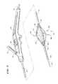
- FIG. 2is a perspective view, with portions broken away, of a device usable in association with the system shown in FIG. 1 having an operative element for contacting tissue shown in a collapsed condition;
- FIG. 3is a perspective view, with portions broken away, of the device shown in FIG. 2 , with the operative element shown in an expanded condition;
- FIG. 4is a perspective view, with portions broken away, of the device shown in FIG. 2 , with the operative element shown in an expanded condition and the electrodes extended for use;
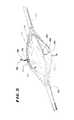
- FIG. 5is an enlarged view of the operative element shown in FIG. 4 , with the electrodes extended for use;
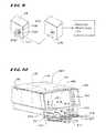
- FIG. 6is a perspective view of a kit containing a device, such as shown in FIGS. 2 to 5 , and a usage key card;
- FIG. 7is an enlarged, mainly schematic view of the usage key card shown in FIG. 6 , embodied as a floppy disk, and also showing the pre-formatted files it contains;
- FIG. 8is a schematic view of a controller, which the system shown in FIG. 1 incorporates, showing the pre-programmed rules by which information contained on the usage key card shown in FIGS. 6 and 7 is read and processed;
- FIG. 9is a schematic view of another processing device that reads information from the usage key card for further processing.
- FIG. 10is a left perspective views of an integrated generator/controller apparatus for use in association with a disposable treatment device, the apparatus including a graphical user interface (GUI) that aids in monitoring and controlling the incidence of use of the disposable treatment device;
- GUIgraphical user interface
- FIG. 11is a representative SETUP display that can be implemented by the GUI shown in FIG. 10 as part of monitoring and controlling the incidence of use of the disposable treatment device;
- FIG. 12is a representative EXCHANGE display that can be implemented by the GUI shown in FIG. 10 as part of monitoring and controlling the incidence of use of the disposable treatment device;
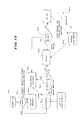
- FIG. 13is a flow chart showing the various states and modes that the apparatus shown in FIG. 10 employs in implementing the GUI in monitoring and controlling the incidence of use of the disposable treatment device.
- FIG. 1shows one embodiment of a system 10 , which monitors and controls the use of an operative element 12 .
- the system 10is well adapted for association with single use, catheter-based devices. Therefore, in the illustrated embodiment, the operative element 12 is part of a catheter-based treatment device 26 . It should be appreciated, however, that the system 10 is also adaptable for use with devices and methods that are not necessarily catheter-based.
- the device 26includes a handle 28 made, e.g., from molded plastic.
- the handle 28is sized to be conveniently held by a physician, to introduce the catheter tube 30 into the targeted tissue region.
- the handle 28carries a flexible catheter tube 30 .
- the catheter tube 30can be constructed, for example, using standard flexible, medical grade plastic materials.
- the catheter tube 30has a distal end 34 , which carries the operative element 12 .
- the operative element 12can support, for example, a device for imaging body tissue, such as an endoscope, or an ultrasound transducer.
- the operative element 12can also support a device to deliver a drug or therapeutic material to body tissue.
- the operative element 12can also support a device for sensing a physiological characteristic in tissue, such as electrical activity, or for transmitting energy to stimulate or form lesions in tissue.
- the device 26in use, is intended to treat dysfunction of sphincters and adjoining tissue regions in the upper gastrointestinal tract, e.g., in the lower esophageal sphincter and adjacent cardia of the stomach, as well as in the lower gastrointestinal tract, e.g., in the intestines, rectum and anal canal.
- the system 10can be used in association with other devices and methods used to treat other dysfunctions elsewhere in the body, which are not necessarily sphincter-related.
- the various aspects of the inventionhave application in procedures requiring ablation of tissue throughout the body, or treatment of hemorrhoids, or restoring compliance to or otherwise tightening interior tissue or muscle regions.
- one function that the operative element 12 is to performis to apply energy in a selective fashion to a targeted body region, which, for the purpose of illustration, can be the lower esophageal sphincter, or cardia, or both.
- the applied energycreates one or more lesions, or a prescribed pattern of lesions, below the mucosal surface of the esophagus or cardia.
- the subsurface lesionsare formed in a manner that preserves and protects the mucosal surface against thermal damage.
- the structure of the operative element 12 to achieve this resultcan vary.
- a representative embodimentis shown in FIGS. 2 to 4 , in which the operative element 12 comprises a three-dimensional basket 56 .
- the basket 56includes one or more spines 58 , and typically includes from four to eight spines 58 , which are assembled together by a distal hub 60 and a proximal base 62 .
- an expandable structure 72comprising a balloon is located within the basket 56 .
- the balloon structure 72can be made, e.g., from a Polyethylene Terephthalate (PET) material, or a polyamide (non-compliant) material, or a radiation cross-linked polyethylene (semi-compliant) material, or a latex material, or a silicone material, or a C-Flex (highly compliant) material.
- the balloon structure 72presents a normally, generally collapsed condition, as FIG. 2 shows. In this condition, the basket 56 is also normally collapsed about the balloon structure 72 , presenting a low profile for deployment into the esophagus 10 .
- the catheter tube 30includes an interior lumen, which communicates with the interior of the balloon structure 72 .
- a fitting 76e.g., a syringe-activated check valve
- the fitting 76communicates with the lumen.
- the fitting 76couples the lumen to a syringe 78 (see FIG. 3 ).
- the syringe 78injects fluid under pressure through the lumen into the balloon structure 72 , causing its expansion.
- Expansion of the balloon structure 72urges the basket 56 to open and expand (see FIG. 3 ).
- the force exerted by the balloon structure 72when expanded, is sufficient to exert an opening force upon the tissue surrounding the basket 56 .
- Each spine 58carries an electrode 66 (see FIG. 4 ).
- each electrode 66is carried within the tubular spine 58 for sliding movement.
- Each electrode 66slides from a retracted position, withdrawn in the spine 58 (shown in FIG. 3 ) and an extended position, extending outward from the spine 58 (see FIG. 4 ) through a hole in the spine 58 .
- a push-pull lever 68 on the handle 28is coupled by one or more interior wires to the sliding electrodes 66 .
- the lever 68controls movement electrodes between the retracted position (by pulling rearward on the lever 68 ) and the extended position (by pushing forward on the lever 68 ).
- the electrodes 66have sufficient distal sharpness and strength, when extended, to penetrate a desired depth into tissue the smooth muscle of the esophageal or cardia 20 wall. The desired depth can range from about 4 mm to about 5 mm.
- the system 10includes a generator 38 to supply the treatment energy to the electrodes 66 .
- the generator 38supplies radio frequency energy, e.g., having a frequency in the range of about 400 kHz to about 10 mHz.
- radio frequency energye.g., having a frequency in the range of about 400 kHz to about 10 mHz.
- other forms of energycan be applied, e.g., coherent or incoherent light; heated or cooled fluid; resistive heating; microwave; ultrasound; a tissue ablation fluid; or cryogenic fluid.
- a cable 40 extending from the proximal end of the handle 28terminates with an electrical connector 42 .
- the cable 40is electrically coupled to the operative element 12 , e.g., by wires that extend through the interior of the handle 28 and catheter tube 30 .
- the connector 42plugs into the generator 38 , to convey the generated energy to the operative element 12 .
- the electrodes 66are formed of material that conducts radio frequency energy, e.g., nickel titanium, stainless steel, e.g., 304 stainless steel, or a combination of nickel titanium and stainless steel.
- an electrical insulating material 70is coated about the proximal end of each electrode 66 .
- the material 70insulates the mucosal surface of the esophagus 10 or cardia 20 from direct exposure to the radio frequency energy. Thermal damage to the mucosal surface is thereby avoided.
- the mucosal surfacecan also be actively cooled during application of radio frequency energy, to further protect the mucosal surface from thermal damage.
- At least one temperature sensor 80is associated with each electrode.
- One temperature sensor 80senses temperature conditions near the exposed distal end of the electrode 66
- a second temperature sensor 80is located on the corresponding spine 58 , which rests against the muscosal surface when the balloon structure 72 is inflated.
- the system 10can also include certain auxiliary processing equipment, e.g., an external fluid delivery apparatus 44 for supplying cooling liquid to the targeted tissue, e.g., through holes in the spines, and an external aspirating apparatus 46 for conveying liquid from the targeted tissue site, e.g., through other holes in the spine or elsewhere on the basket 56 .
- auxiliary processing equipmente.g., an external fluid delivery apparatus 44 for supplying cooling liquid to the targeted tissue, e.g., through holes in the spines
- an external aspirating apparatus 46for conveying liquid from the targeted tissue site, e.g., through other holes in the spine or elsewhere on the basket 56 .
- the system 10also includes a controller 52 .
- the controller 52which preferably includes a central processing unit (CPU), is linked to the generator 38 , the fluid delivery apparatus 44 , and the aspirating apparatus 46 .
- the aspirating apparatus 46can comprise a conventional vacuum source typically present in a physician's suite, which operates continuously, independent of the controller 52 .
- the controller 52governs the delivery of processing fluid and, if desired, the removal of aspirated material.
- the controller 52also governs the power levels, cycles, and duration that the radio frequency energy is distributed to the electrodes 66 , to achieve and maintain power levels appropriate to achieve the desired treatment objectives.
- the controller 52can condition the electrodes 66 to operate in a monopolar mode. In this mode, each electrode 66 serves as a transmitter of energy, and an indifferent patch electrode (not shown) serves as a common return for all electrodes 66 .
- the controller 52can condition the electrodes 66 to operate in a bipolar mode. In this mode, one of the electrodes comprises the transmitter and another electrode comprises the return for the transmitted energy.
- the bipolar electrode pairscan electrodes 66 on adjacent spines, or electrodes 66 spaced more widely apart on different spines.
- the controller 52includes an input/output (I/O) device 54 .
- the I/O device 54allows the physician to input control and processing variables, to enable the controller 52 to generate appropriate command signals.
- the I/O device 54also receives real time processing feedback information from the temperature sensors 80 , for processing by the controller 52 , e.g., to govern the application of energy and the delivery of processing fluid.
- the I/O device 54also includes a graphical user interface (GUI), to graphically present processing information to the physician for viewing or analysis.
- GUIgraphical user interface
- the handle 28 and the catheter tube 30form an integrated construction intended for a single use and subsequent disposal as a unit.
- the handle 28can comprise a nondisposable component intended for multiple uses.
- the catheter tube 30 , and components carried at the end of the catheter tube 30comprise a disposable assembly, which the physician releasably connects to the handle 28 at time of use and disconnects and discards after use.
- the catheter tube 30can, for example, include a male plug connector that couples to a female plug receptacle on the handle 28 .
- the controller 52includes a module 48 that controls use of the device 26 .
- the device 26is supplied as part of a kit 200 that includes, together with the device 26 , a usage key card 202 .
- the kit 200packages the device 26 and usage key card 202 as a unitary, single use item in a sterile fashion within peripherally sealed sheets of plastic film material that are torn or peeled away at the instance of use.
- the presence of the device 26 and user key card 202 packaged together in the kit 200verifies to the physician or user that device 26 is sterile and has not be subjected to prior use. The physician or user is thereby assured that the device 26 meets established performance and sterility specifications. No unused device 26 is supplied in the kit 200 without a usage key card 202 , and vice versa.
- the usage key card 202incorporates a storage medium 204 that is readable by the module 48 .
- the storage medium 204contains information that enables at least two use control and monitoring functions.
- the first use control and monitoring function of the usage key card 202occurs prior to use of the device 26 in association with the generator 38 .
- the physicianmust first present the usage key card 202 for reading by the module 48 .
- the controller 52must then find that the usage key card 202 meets the criteria necessary for its registration by the controller 52 .
- the criteriaare designed to indicate the absence of a prior use, either in absolute terms or in terms of a period of use outside a predetermined time period. If the criteria are not met, the controller 52 will not register the usage key card 202 , and the controller 52 will also not enable use of the generator 38 in association with the device 26 . Further details of the registration function of the controller 52 will be described later.
- the second use control and monitoring function of the usage key card 202occurs if the criteria are met and registration of the usage key card 202 occurs.
- the storage medium 204 of the usage key card 202remains in the module 48 and receives, via the module 48 , data generated by the controller 52 recording operating parameters and performance of the device 26 .
- the storage medium 204 of the usage key card 202retains and organizes the data for further off-line storage and processing. Further details of the data retention function will be described later.
- the usage key card 202can be variously configured.
- the usage key card 202comprises a computer-readable storage medium 204 housed within a conventional 3.5 inch floppy disk 206 .
- the module 48comprises a conventional floppy disk drive 208 (see FIG. 8 ) capable of reading data from and downloading data to the storage medium 204 of the disk 206 .
- the usage key card 202can take the form of a PC card, flash memory device, or magnetic card.
- the module 48comprises a data reading and writing device compatible with the storage medium of the card 202 .
- the storage medium 204 of the usage key card 202contains at least two pre-formatted files 210 and 212 .
- the first file 210contains a unique identification code 214 capable of being read by the module 48 and registered by the controller 52 .
- the second file 212is formatted to receive and retain operational and performance data generated by the controller 52 to create from it a procedure log 220 .
- the identification code 214 contained in the first file 210is created to be unique to the particular usage key card 202 . That is, each usage key card 202 contains its own unique identification code 214 . No two usage key cards share the same identification code 214 .
- the unique identification code 214can comprise, e.g., a serial number uniquely assigned to the particular device 26 found in the kit 200 , or any other unique code that is not repeated for any other usage key card 202 .
- the code 214itself can comprise letters, numbers, or combinations thereof.
- the module 48reads the identification code 214 off the usage key card 202 for input to the controller 52 .
- This identification codewill be called the “instant identification code.”
- the controller 52constructs and maintains in non-volatile memory a use table 216 .
- the use table 216contains all prior identification codes that meet the criteria to be registered by the controller 52 . These identification codes will be called the “registered identification codes.”
- the controller 52compares the instant identification code 214 to all registered identification codes contained in the table 216 . In the absence of a match between the instant identification code and any registered identification code, the controller 52 updates the table, i.e., the controller 52 registers the instant identification code by adding it to the table 216 . Upon registering the usage key card 202 , the controller 52 also enables use of generator 38 in association with the device.
- the controller 52does not add the duplicative identification code to the table 216 and does not enable use of the generator 38 in association with any device 26 .
- the controller 52outputs to the GUI notice of prior use.
- the controller 52maintains for each registered identification code in the table 216 a time record 218 .
- the time record 218contains a value reflecting the period of time during which energy was applied by the generator 38 during the previous permitted use.
- the controller 52ascertains whether the time period of previous use contained in the record 218 is less than a prescribed maximum time period, e.g., 45 minutes. If so, the controller 52 enables a subsequent operation of the generator 38 in association with the device 26 , but only for the time period remaining.
- the controller 52updates the time record 218 as further use occurs.
- the controller 52preferably outputs to the GUI the time period of permitted use remaining.
- the controller 52If the controller 52 ascertains that the time period of previous use equals or exceeds the prescribed maximum time period, the controller 52 does not enable use of the generator 38 . Preferably, the controller 52 outputs to the GUI notice of prior use.
- the second file 212 contained on the storage medium 204 of the usage key card 202is formatted to receive, via the module 48 , data that is generated by the controller 52 during permitted use of the device 26 in association with the generator 38 .
- the file 212retains the data in a formatted array according to pre-programmed rules to create a procedure log 220 .
- the content of the formatted log 220can vary.
- the log 220can document, by date of treatment and number of treatments, the coagulation level (i.e., the depth at which the electrodes are inserted), the time duration of energy application, the magnitude of energy delivered by each electrode, and the coolant flow rate.
- the procedure log 220can also record at pre-established intervals (e.g., every 5 seconds) the temperatures of the electrodes and surrounding tissue, along other parameters, e.g., sensed impedance and power delivered by each electrode.
- the procedure log 220preferably records these values in a pre-formatted data base format, to enable import of the values as data base items for storage, processing, and retrieval by an off-line data processing device 222 having a compatible data base processing application.
- the off-line data processing device 222reads processing log data from the usage key card 202 (via a floppy disk drive 230 or otherwise compatible reading device).
- the device 222can process the data in various ways according to the rules of the data processing application.
- the device 222can, e.g., create a print-formatted record of the procedure log 220 for printing in a hard copy version.
- the device 222can also, e.g., process the procedure logs for multiple devices and patients, to create historical patient treatment records, patient reimbursement records, and the like for storage or retrieval.
- the device 222thereby makes possible the establishment and maintenance of an archival patient database by processing individual procedure logs.
- the kit 200can also include a label 224 that is pre-applied or that can be applied by the physician to the usage key card 202 .
- the label 224receives manually transcribed, visually readable information pertaining to the usage key card 202 , e.g., the name of the patient being treated by the device 26 , the date of treatment, and the like. In this way, usage key cards 202 can itself be physically stored and indexed.
- the kit 200can also include instructions 232 for using the usage key card 202 in the fashion described.
- the instructions 232can instruct the physician as to the need for having the usage key card 202 read by the module 48 , in order to enable use of the device 26 in association with the generator 38 .
- the instructions 232can also instruct the physician regarding the content of the procedure log and the subsequent off-line processing options that are available.
- the storage medium 204 of the usage key card 202can also contain at least one additional formatted file 226 that provides device information 228 , which characterizes the device 26 supplied in the kit 200 .
- the device information 228when read by the module 48 , can identify the type of device 26 in terms of its operational characteristics, the inclusion of temperature sensing, and reuse criteria (e.g., no reuse after a single use, or multiple uses permitted up a prescribed maximum number of uses, or multiple uses permitted up to a maximum time period of use, or multiple uses permitted up to a maximum application of RF energy).
- the file 226can also condition the GUI to display the desired images and data formats, which change depending upon the treatment procedure using the device (e.g, treatment of GERD, fecal incontinence, or urinary incontinence).
- the controller 52can compare the device characteristics with the operational characteristics of the controller 52 and generator 38 , and disable operation of the device 26 should the characteristics of the device 26 be incompatible with the characteristics of the controller 52 and/or generator 38 .
- GUIGraphical User Interface
- the radio frequency generator 38 , the controller 52 with I/O device 54 , and the fluid delivery apparatus 44are integrated within a single housing 400 .
- the I/O device 54includes input connectors 402 , 404 , and 406 .
- the connector 402accepts an electrical connector 408 , to which the connector 42 of the selected treatment device 26 is electrically coupled for use.
- the connector 404accepts an electrical connector 410 coupled to a patch electrode 412 (for mono-polar operation).
- the connector 406accepts an pneumatic connector 414 coupled to a conventional foot pedal 416 , when, when depressed, causes the delivery of radio frequency energy to the electrodes 66 on the device 26 .
- These connectors 402 , 404 , and 406couple these external devices to the controller 52 .
- the I/O device 54also couples the controller 52 to an array of membrane keypads 422 and other indicator lights on the housing 400 , for entering and indicating parameters governing the operation of the controller 52 .
- the I/O device 54also couples the controller 52 to a display microprocessor 474 .
- the microprocessor 474comprises, e.g., a dedicated Pentium®-based central processing unit.
- the controller 52transmits data to the microprocessor 474 , and the microprocessor 474 acknowledges correct receipt of the data and formats the data for meaningful display to the physician.
- the dedicated display microprocessor 474exerts no control over the controller 52 .
- the controller 52comprises an 68HC11 processor having an imbedded operating system.
- the controller 52can comprise another style of processor, and the operating system can reside as process software on a hard drive coupled to the CPU, which is down loaded to the CPU during system initialization and startup.
- the display microprocessor 474is coupled to a graphics display monitor 420 in the housing 400 .
- the controller 52implements through the display microprocessor 474 the graphical user interface, or GUI, which is displayed on the display monitor 420 .
- the GUIcan be realized, e.g., as a “C” language program implemented by the microprocessor 474 using the MS WINDOWSTM or NT application and the standard WINDOWS 32 API controls, e.g., as provided by the WINDOWSTM Development Kit, along with conventional graphics software disclosed in public literature.
- the display microprocessor 474is also itself coupled to the floppy disk drive 208 , previously described.
- the display microprocessor 474can also be coupled to a keyboard, printer, and include one or more parallel port links and one or more conventional serial RS-232C port links or EthernetTM communication links.
- the operating systemUpon boot-up of the CPU (see FIG. 13 ), the operating system implements the START-UP function 510 for the GUI 424 .
- the GUI 424displays an appropriate start-up logo and title image (not shown), while the controller 52 performs a self-test.
- the controller 52Upon completion of the START-UP function (see FIG. 13 ), the controller 52 conducts a CHECK function 512 .
- the function 512checks for the presence of a usage key card 202 in the floppy disk drive 208 . As before described, a valid usage key card 202 is a prerequisite for using a given treatment device 26 .
- FIG. 11shows a representative SETUP prompt 500 .
- the SETUP prompt 500leads the operator in a step-wise fashion through the tasks required to enable use of the generator 38 .
- a first graphic fielddisplays one or more icons and/or alpha-numeric indicia 502 that prompt the operator to connect the electrical connector 42 of the treatment device 26 to the connector cable 408 .
- a second graphic fielddisplays one or more icons and/or alpha-numeric indicia 504 that prompt the operator to insert a valid user key card 202 (i.e., floppy disk).
- a third graphic fielddisplays one or more icons and/or alpha-numeric indicia 506 that prompt the user to select the standby-ready button 430 on the housing 400 (see FIG. 10 ).
- the actuation of the standby-ready button 430causes the controller 52 to enter the STAND-BY mode 508 (see FIG. 13 ).
- the controller 52executes the REGISTRATION function 514 , to determine whether the user key card 202 inserted in the drive 208 contains a valid identification code 214 .
- the identification code 214will not be deemed valid when the code already exists in the use table 216 of the controller 52 with a time record 218 equal to or greater than the prescribed maximum, thereby indicating a completed prior use of the device 26 .
- the REGISTRATION function 514commands the display microprocessor 474 to generate an EXCHANGE prompt 516 on the graphics display monitor 420 .
- FIG. 12shows a representative EXCHANGE prompt 516 .
- the EXCHANGE prompt 516leads the operator in a step-wise fashion through the tasks of replacing the previously used device 26 and its key card 202 with a new device 26 and its associated key card 202 .
- a first graphic fielddisplays one or more icons and/or alpha-numeric indicia 518 that prompt the operator to disconnect the electrical connector 42 of the previously used treatment device 26 and to connect a new treatment device 26 .
- a second graphic fielddisplays one or more icons and/or alpha-numeric indicia 520 that prompt the operator to remove the old user key card 202 and insert the new key card 202 that accompanied the new treatment device 26 in the kit 200 .
- a third graphic fielddisplays one or more icons and/or alpha-numeric indicia 522 that prompt the user to again select the standby-ready button 430 on the housing 400 .
- selection of the standby-ready button 430causes the controller 52 to again enter the STAND-BY mode 508 , and again execute the REGISTRATION function 514 (see FIG. 13 ).
- the presence of a valid identification code 214 on the user card 202causes the controller 52 to enter the READY mode 524 .
- the operatordeploys the treatment device 26 to the intended treatment site.
- the operatorlocates the electrodes 66 in the desired orientation.
- the operatordepresses the foot pedal 416 (or selects the standby-ready button 430 ).
- the controller 52executes a prescribed PAUSE state 528 (e.g., 8 seconds), and then commands the generator 38 to apply radio frequency energy through the electrodes 66 carried by the treatment device 26 .
- the controller 52includes an UPDATE function 526 (see FIG. 13 ).
- the UPDATE function 526registers the time period during which radio frequency energy is applied using the device 26 . The time is entered into the time record 218 of the use table 216 maintained by the controller 52 . After a prescribed maximum period of use is registered (e.g., sixty minutes), the UPDATE function 526 interrupts application of radio frequency energy to the electrodes 66 , and prevents further delivery by the generator 38 to the particular device 26 .
- the UPDATE function 526causes the controller 52 to generate the EXCHANGE prompt 516 .
- the EXCHANGE prompt 516requires the operator to replace the existing device 26 and its key card 200 with a new device 26 and its associated key card 200 .
- the controller 52while radio frequency energy is being applied during the READY mode 524 , the controller 52 preferably monitors impedance and/or temperature conditions at the treatment site.
- the controller 52enters a DEFAULT mode 530 and returns to the PAUSE state 528 when certain localized impedance and/or temperature conditions are sensed, e.g., when impedance is outside a prescribed range (for example, less than 50 ohms or greater than 1000 ohms); or electrode tip temperature exceeds 100 degrees C.; or tissue surface temperature exceeds 50 degrees C.
- the controller 52prevents the application of radio frequency energy through the electrodes 66 for a prescribed period of time (e.g., 8 seconds), after which operation of the generator 38 using the foot pedal 416 or standby-ready button 430 is restored.
- a prescribed period of timee.g. 8 seconds
Landscapes
- Health & Medical Sciences (AREA)
- Surgery (AREA)
- Life Sciences & Earth Sciences (AREA)
- Engineering & Computer Science (AREA)
- Public Health (AREA)
- Animal Behavior & Ethology (AREA)
- Veterinary Medicine (AREA)
- Nuclear Medicine, Radiotherapy & Molecular Imaging (AREA)
- General Health & Medical Sciences (AREA)
- Biomedical Technology (AREA)
- Heart & Thoracic Surgery (AREA)
- Medical Informatics (AREA)
- Molecular Biology (AREA)
- Physics & Mathematics (AREA)
- Otolaryngology (AREA)
- Electromagnetism (AREA)
- Plasma & Fusion (AREA)
- Pathology (AREA)
- Oral & Maxillofacial Surgery (AREA)
- Cardiology (AREA)
- Human Computer Interaction (AREA)
- Robotics (AREA)
- Surgical Instruments (AREA)
Abstract
Description
Claims (20)
Priority Applications (2)
| Application Number | Priority Date | Filing Date | Title |
|---|---|---|---|
| US13/084,973US8845632B2 (en) | 2000-05-18 | 2011-04-12 | Graphical user interface for monitoring and controlling use of medical devices |
| US14/492,046US9675403B2 (en) | 2000-05-18 | 2014-09-21 | Graphical user interface for monitoring and controlling use of medical devices |
Applications Claiming Priority (4)
| Application Number | Priority Date | Filing Date | Title |
|---|---|---|---|
| US09/574,704US6464689B1 (en) | 1999-09-08 | 2000-05-18 | Graphical user interface for monitoring and controlling use of medical devices |
| US10/219,798US6994704B2 (en) | 2000-01-31 | 2002-08-15 | Graphical user interface for monitoring and controlling use of medical devices |
| US11/299,955US7922715B2 (en) | 2000-01-31 | 2005-12-12 | Graphical user interface for monitoring and controlling use of medical devices |
| US13/084,973US8845632B2 (en) | 2000-05-18 | 2011-04-12 | Graphical user interface for monitoring and controlling use of medical devices |
Related Parent Applications (1)
| Application Number | Title | Priority Date | Filing Date |
|---|---|---|---|
| US11/299,955ContinuationUS7922715B2 (en) | 2000-01-31 | 2005-12-12 | Graphical user interface for monitoring and controlling use of medical devices |
Related Child Applications (1)
| Application Number | Title | Priority Date | Filing Date |
|---|---|---|---|
| US14/492,046ContinuationUS9675403B2 (en) | 2000-05-18 | 2014-09-21 | Graphical user interface for monitoring and controlling use of medical devices |
Publications (2)
| Publication Number | Publication Date |
|---|---|
| US20110190759A1 US20110190759A1 (en) | 2011-08-04 |
| US8845632B2true US8845632B2 (en) | 2014-09-30 |
Family
ID=44342273
Family Applications (2)
| Application Number | Title | Priority Date | Filing Date |
|---|---|---|---|
| US13/084,973Expired - Fee RelatedUS8845632B2 (en) | 2000-05-18 | 2011-04-12 | Graphical user interface for monitoring and controlling use of medical devices |
| US14/492,046Expired - Fee RelatedUS9675403B2 (en) | 2000-05-18 | 2014-09-21 | Graphical user interface for monitoring and controlling use of medical devices |
Family Applications After (1)
| Application Number | Title | Priority Date | Filing Date |
|---|---|---|---|
| US14/492,046Expired - Fee RelatedUS9675403B2 (en) | 2000-05-18 | 2014-09-21 | Graphical user interface for monitoring and controlling use of medical devices |
Country Status (1)
| Country | Link |
|---|---|
| US (2) | US8845632B2 (en) |
Cited By (3)
| Publication number | Priority date | Publication date | Assignee | Title |
|---|---|---|---|---|
| US11269762B2 (en)* | 2019-03-25 | 2022-03-08 | Aurora Labs Ltd. | Using line-of-code behavior and relation models to anticipate impact of hardware changes |
| US11759271B2 (en) | 2017-04-28 | 2023-09-19 | Stryker Corporation | System and method for indicating mapping of console-based surgical systems |
| US12220157B2 (en)* | 2017-06-05 | 2025-02-11 | St. Jude Medical, Cardiology Division, Inc. | Pulmonary antrum radial-linear ablation devices |
Families Citing this family (5)
| Publication number | Priority date | Publication date | Assignee | Title |
|---|---|---|---|---|
| US9364277B2 (en) | 2012-12-13 | 2016-06-14 | Cook Medical Technologies Llc | RF energy controller and method for electrosurgical medical devices |
| US9204921B2 (en) | 2012-12-13 | 2015-12-08 | Cook Medical Technologies Llc | RF energy controller and method for electrosurgical medical devices |
| US9597140B2 (en)* | 2014-01-31 | 2017-03-21 | Medtronic Cryocath Lp | Accessory to allow sensing at balloon interface |
| US11896823B2 (en) | 2017-04-04 | 2024-02-13 | Btl Healthcare Technologies A.S. | Method and device for pelvic floor tissue treatment |
| US11172984B2 (en)* | 2019-05-03 | 2021-11-16 | Biosense Webster (Israel) Ltd. | Device, system and method to ablate cardiac tissue |
Citations (187)
| Publication number | Priority date | Publication date | Assignee | Title |
|---|---|---|---|---|
| US1798902A (en) | 1928-11-05 | 1931-03-31 | Edwin M Raney | Surgical instrument |
| DE1838840U (en) | 1961-07-18 | 1961-10-05 | Mauser Kg | SEATING FURNITURE. |
| US3517128A (en) | 1968-02-08 | 1970-06-23 | James R Hines | Surgical expanding arm dilator |
| US3901241A (en) | 1973-05-31 | 1975-08-26 | Al Corp Du | Disposable cryosurgical instrument |
| US4011872A (en) | 1974-04-01 | 1977-03-15 | Olympus Optical Co., Ltd. | Electrical apparatus for treating affected part in a coeloma |
| US4196724A (en) | 1978-01-31 | 1980-04-08 | Frecker William H | Tongue locking device |
| US4411266A (en) | 1980-09-24 | 1983-10-25 | Cosman Eric R | Thermocouple radio frequency lesion electrode |
| US4423812A (en) | 1980-09-18 | 1984-01-03 | Olympus Optical Company Limited | Cassette receptacle device |
| US4532924A (en) | 1980-05-13 | 1985-08-06 | American Hospital Supply Corporation | Multipolar electrosurgical device and method |
| US4565200A (en) | 1980-09-24 | 1986-01-21 | Cosman Eric R | Universal lesion and recording electrode system |
| US4705041A (en) | 1984-07-06 | 1987-11-10 | Kim Il G | Dilator for Sphincter of Oddi |
| US4858615A (en) | 1981-11-10 | 1989-08-22 | Sentron V.O.F. | Catheter sensor and memory unit |
| US4901737A (en) | 1987-04-13 | 1990-02-20 | Toone Kent J | Method and therapeutic apparatus for reducing snoring |
| US4906203A (en) | 1988-10-24 | 1990-03-06 | General Motors Corporation | Electrical connector with shorting clip |
| US4907589A (en) | 1988-04-29 | 1990-03-13 | Cosman Eric R | Automatic over-temperature control apparatus for a therapeutic heating device |
| EP0139607B1 (en) | 1983-10-07 | 1990-04-11 | Yeda Research And Development Company, Ltd. | Hyperthermia apparatus |
| US4943290A (en) | 1987-06-23 | 1990-07-24 | Concept Inc. | Electrolyte purging electrode tip |
| US4947842A (en) | 1988-09-22 | 1990-08-14 | Medical Engineering And Development Institute, Inc. | Method and apparatus for treating tissue with first and second modalities |
| US4955377A (en) | 1988-10-28 | 1990-09-11 | Lennox Charles D | Device and method for heating tissue in a patient's body |
| US4966597A (en) | 1988-11-04 | 1990-10-30 | Cosman Eric R | Thermometric cardiac tissue ablation electrode with ultra-sensitive temperature detection |
| US4976711A (en) | 1989-04-13 | 1990-12-11 | Everest Medical Corporation | Ablation catheter with selectively deployable electrodes |
| WO1991001773A1 (en) | 1989-08-01 | 1991-02-21 | Enrico Mangieri | Percutaneous mechanical dilating catheter for cardiac valves and blood vessels |
| US5019075A (en) | 1984-10-24 | 1991-05-28 | The Beth Israel Hospital | Method and apparatus for angioplasty |
| US5035696A (en) | 1990-02-02 | 1991-07-30 | Everest Medical Corporation | Electrosurgical instrument for conducting endoscopic retrograde sphincterotomy |
| US5047028A (en) | 1989-05-12 | 1991-09-10 | Quinghua Qian | Method for inducing thrombosis in blood vessels |
| US5046512A (en) | 1989-03-10 | 1991-09-10 | Murchie John A | Method and apparatus for treatment of snoring |
| US5057107A (en) | 1989-04-13 | 1991-10-15 | Everest Medical Corporation | Ablation catheter with selectively deployable electrodes |
| US5078717A (en) | 1989-04-13 | 1992-01-07 | Everest Medical Corporation | Ablation catheter with selectively deployable electrodes |
| US5083565A (en) | 1990-08-03 | 1992-01-28 | Everest Medical Corporation | Electrosurgical instrument for ablating endocardial tissue |
| US5084044A (en) | 1989-07-14 | 1992-01-28 | Ciron Corporation | Apparatus for endometrial ablation and method of using same |
| US5088979A (en) | 1990-10-11 | 1992-02-18 | Wilson-Cook Medical Inc. | Method for esophageal invagination and devices useful therein |
| US5094233A (en) | 1991-01-11 | 1992-03-10 | Brennan Louis G | Turbinate sheath device |
| US5100423A (en) | 1990-08-21 | 1992-03-31 | Medical Engineering & Development Institute, Inc. | Ablation catheter |
| US5106360A (en) | 1987-09-17 | 1992-04-21 | Olympus Optical Co., Ltd. | Thermotherapeutic apparatus |
| US5122137A (en) | 1990-04-27 | 1992-06-16 | Boston Scientific Corporation | Temperature controlled rf coagulation |
| WO1992010142A1 (en) | 1990-12-10 | 1992-06-25 | Howmedica Inc. | A device and method for interstitial laser energy delivery |
| US5125928A (en) | 1989-04-13 | 1992-06-30 | Everest Medical Corporation | Ablation catheter with selectively deployable electrodes |
| US5156151A (en) | 1991-02-15 | 1992-10-20 | Cardiac Pathways Corporation | Endocardial mapping and ablation system and catheter probe |
| US5190541A (en) | 1990-10-17 | 1993-03-02 | Boston Scientific Corporation | Surgical instrument and method |
| US5197964A (en) | 1991-11-12 | 1993-03-30 | Everest Medical Corporation | Bipolar instrument utilizing one stationary electrode and one movable electrode |
| US5197963A (en) | 1991-12-02 | 1993-03-30 | Everest Medical Corporation | Electrosurgical instrument with extendable sheath for irrigation and aspiration |
| US5205287A (en) | 1990-04-26 | 1993-04-27 | Hoechst Aktiengesellschaft | Ultrasonic contrast agents, processes for their preparation and the use thereof as diagnostic and therapeutic agents |
| WO1993008755A1 (en) | 1991-11-08 | 1993-05-13 | Ep Technologies, Inc. | Ablation electrode with insulated temperature sensing elements |
| US5215103A (en) | 1986-11-14 | 1993-06-01 | Desai Jawahar M | Catheter for mapping and ablation and method therefor |
| US5233515A (en) | 1990-06-08 | 1993-08-03 | Cosman Eric R | Real-time graphic display of heat lesioning parameters in a clinical lesion generator system |
| US5232444A (en) | 1988-06-25 | 1993-08-03 | Just Hansjoerg | Dilatation catheter |
| US5236413A (en) | 1990-05-07 | 1993-08-17 | Feiring Andrew J | Method and apparatus for inducing the permeation of medication into internal tissue |
| US5242441A (en) | 1992-02-24 | 1993-09-07 | Boaz Avitall | Deflectable catheter with rotatable tip electrode |
| US5254126A (en) | 1992-06-24 | 1993-10-19 | Ethicon, Inc. | Endoscopic suture punch |
| US5256138A (en) | 1990-10-04 | 1993-10-26 | The Birtcher Corporation | Electrosurgical handpiece incorporating blade and conductive gas functionality |
| US5257451A (en) | 1991-11-08 | 1993-11-02 | Ep Technologies, Inc. | Method of making durable sleeve for enclosing a bendable electrode tip assembly |
| US5263493A (en) | 1992-02-24 | 1993-11-23 | Boaz Avitall | Deflectable loop electrode array mapping and ablation catheter for cardiac chambers |
| US5275162A (en) | 1991-11-08 | 1994-01-04 | Ep Technologies, Inc. | Valve mapping catheter |
| US5275610A (en) | 1991-05-13 | 1994-01-04 | Cook Incorporated | Surgical retractors and method of use |
| US5275608A (en) | 1991-10-16 | 1994-01-04 | Implemed, Inc. | Generic endoscopic instrument |
| US5277201A (en) | 1992-05-01 | 1994-01-11 | Vesta Medical, Inc. | Endometrial ablation apparatus and method |
| US5281216A (en) | 1992-03-31 | 1994-01-25 | Valleylab, Inc. | Electrosurgical bipolar treating apparatus |
| US5281217A (en) | 1992-04-13 | 1994-01-25 | Ep Technologies, Inc. | Steerable antenna systems for cardiac ablation that minimize tissue damage and blood coagulation due to conductive heating patterns |
| US5281218A (en) | 1992-06-05 | 1994-01-25 | Cardiac Pathways Corporation | Catheter having needle electrode for radiofrequency ablation |
| US5292321A (en) | 1990-06-08 | 1994-03-08 | Lee Benjamin I | Thermal balloon angioplasty with thermoplastic stent |
| US5293869A (en) | 1992-09-25 | 1994-03-15 | Ep Technologies, Inc. | Cardiac probe with dynamic support for maintaining constant surface contact during heart systole and diastole |
| US5309910A (en) | 1992-09-25 | 1994-05-10 | Ep Technologies, Inc. | Cardiac mapping and ablation systems |
| US5314466A (en) | 1992-04-13 | 1994-05-24 | Ep Technologies, Inc. | Articulated unidirectional microwave antenna systems for cardiac ablation |
| US5313943A (en) | 1992-09-25 | 1994-05-24 | Ep Technologies, Inc. | Catheters and methods for performing cardiac diagnosis and treatment |
| WO1994010925A1 (en) | 1992-11-13 | 1994-05-26 | American Cardiac Ablation Co., Inc. | Fluid cooled electrosurgical cauterization system |
| US5316020A (en) | 1990-10-03 | 1994-05-31 | Ernest Truffer | Snoring prevention device |
| US5324284A (en) | 1992-06-05 | 1994-06-28 | Cardiac Pathways, Inc. | Endocardial mapping and ablation system utilizing a separately controlled ablation catheter and method |
| US5328467A (en) | 1991-11-08 | 1994-07-12 | Ep Technologies, Inc. | Catheter having a torque transmitting sleeve |
| US5334196A (en) | 1992-10-05 | 1994-08-02 | United States Surgical Corporation | Endoscopic fastener remover |
| US5336222A (en) | 1993-03-29 | 1994-08-09 | Boston Scientific Corporation | Integrated catheter for diverse in situ tissue therapy |
| US5345936A (en) | 1991-02-15 | 1994-09-13 | Cardiac Pathways Corporation | Apparatus with basket assembly for endocardial mapping |
| US5348554A (en) | 1992-12-01 | 1994-09-20 | Cardiac Pathways Corporation | Catheter for RF ablation with cooled electrode |
| WO1994021178A1 (en) | 1993-03-23 | 1994-09-29 | Goldrath Milton H | Verres needle suturing device |
| WO1994021165A1 (en) | 1993-03-16 | 1994-09-29 | Ep Technologies, Inc. | Guide sheaths for cardiac mapping and ablation |
| WO1994022366A1 (en) | 1993-04-07 | 1994-10-13 | Cardiac Pathways Corporation | Apparatus and method for ventricular mapping and ablation |
| US5363347A (en) | 1994-02-24 | 1994-11-08 | Hap Nguyen | Vending tanning timer |
| US5363861A (en) | 1991-11-08 | 1994-11-15 | Ep Technologies, Inc. | Electrode tip assembly with variable resistance to bending |
| US5366490A (en) | 1992-08-12 | 1994-11-22 | Vidamed, Inc. | Medical probe device and method |
| US5365926A (en) | 1986-11-14 | 1994-11-22 | Desai Jawahar M | Catheter for mapping and ablation and method therefor |
| US5365945A (en) | 1993-04-13 | 1994-11-22 | Halstrom Leonard W | Adjustable dental applicance for treatment of snoring and obstructive sleep apnea |
| WO1994026178A1 (en) | 1993-05-14 | 1994-11-24 | Vidamed, Inc. | Bph ablation method and apparatus |
| US5368557A (en) | 1991-01-11 | 1994-11-29 | Baxter International Inc. | Ultrasonic ablation catheter device having multiple ultrasound transmission members |
| US5368592A (en) | 1992-04-13 | 1994-11-29 | Ep Technologies, Inc. | Articulated systems for cardiac ablation |
| US5370678A (en) | 1992-04-13 | 1994-12-06 | Ep Technologies, Inc. | Steerable microwave antenna systems for cardiac ablation that minimize tissue damage and blood coagulation due to conductive heating patterns |
| US5383874A (en)* | 1991-11-08 | 1995-01-24 | Ep Technologies, Inc. | Systems for identifying catheters and monitoring their use |
| US5383917A (en) | 1991-07-05 | 1995-01-24 | Jawahar M. Desai | Device and method for multi-phase radio-frequency ablation |
| US5383876A (en) | 1992-11-13 | 1995-01-24 | American Cardiac Ablation Co., Inc. | Fluid cooled electrosurgical probe for cutting and cauterizing tissue |
| DE4303882C2 (en) | 1993-02-10 | 1995-02-09 | Kernforschungsz Karlsruhe | Combination instrument for separation and coagulation for minimally invasive surgery |
| US5397339A (en) | 1986-11-14 | 1995-03-14 | Desai; Jawahar M. | Catheter for mapping and ablation and method therefor |
| US5398683A (en) | 1991-05-24 | 1995-03-21 | Ep Technologies, Inc. | Combination monophasic action potential/ablation catheter and high-performance filter system |
| US5401272A (en) | 1992-09-25 | 1995-03-28 | Envision Surgical Systems, Inc. | Multimodality probe with extendable bipolar electrodes |
| US5403311A (en) | 1993-03-29 | 1995-04-04 | Boston Scientific Corporation | Electro-coagulation and ablation and other electrotherapeutic treatments of body tissue |
| US5409483A (en) | 1993-01-22 | 1995-04-25 | Jeffrey H. Reese | Direct visualization surgical probe |
| US5409453A (en) | 1992-08-12 | 1995-04-25 | Vidamed, Inc. | Steerable medical probe with stylets |
| US5415657A (en) | 1992-10-13 | 1995-05-16 | Taymor-Luria; Howard | Percutaneous vascular sealing method |
| US5421819A (en) | 1992-08-12 | 1995-06-06 | Vidamed, Inc. | Medical probe device |
| US5423808A (en) | 1991-11-08 | 1995-06-13 | Ep Technologies, Inc. | Systems and methods for radiofrequency ablation with phase sensitive power detection |
| US5423812A (en) | 1994-01-31 | 1995-06-13 | Ellman; Alan G. | Electrosurgical stripping electrode for palatopharynx tissue |
| WO1995018575A1 (en) | 1994-01-06 | 1995-07-13 | Vidamed, Inc. | Medical probe apparatus with enhanced rf, resistance heating, and microwave ablation capabilities |
| US5433739A (en) | 1993-11-02 | 1995-07-18 | Sluijter; Menno E. | Method and apparatus for heating an intervertebral disc for relief of back pain |
| WO1995019142A1 (en) | 1994-01-12 | 1995-07-20 | Vidamed, Inc. | Thermal mapping catheter with ultrasound probe |
| US5435805A (en) | 1992-08-12 | 1995-07-25 | Vidamed, Inc. | Medical probe device with optical viewing capability |
| US5441499A (en) | 1993-07-14 | 1995-08-15 | Dekna Elektro-U. Medizinische Apparatebau Gesellschaft Mbh | Bipolar radio-frequency surgical instrument |
| US5443470A (en) | 1992-05-01 | 1995-08-22 | Vesta Medical, Inc. | Method and apparatus for endometrial ablation |
| WO1995025472A1 (en) | 1994-03-23 | 1995-09-28 | Vidamed, Inc. | Dual-channel rf power delivery system |
| US5456662A (en) | 1993-02-02 | 1995-10-10 | Edwards; Stuart D. | Method for reducing snoring by RF ablation of the uvula |
| US5458596A (en) | 1994-05-06 | 1995-10-17 | Dorsal Orthopedic Corporation | Method and apparatus for controlled contraction of soft tissue |
| US5458597A (en) | 1993-11-08 | 1995-10-17 | Zomed International | Device for treating cancer and non-malignant tumors and methods |
| US5465717A (en) | 1991-02-15 | 1995-11-14 | Cardiac Pathways Corporation | Apparatus and Method for ventricular mapping and ablation |
| US5470308A (en) | 1992-08-12 | 1995-11-28 | Vidamed, Inc. | Medical probe with biopsy stylet |
| US5472441A (en) | 1993-11-08 | 1995-12-05 | Zomed International | Device for treating cancer and non-malignant tumors and methods |
| US5471982A (en) | 1992-09-29 | 1995-12-05 | Ep Technologies, Inc. | Cardiac mapping and ablation systems |
| WO1996000042A1 (en) | 1994-06-24 | 1996-01-04 | Vidacare International | Thin layer ablation apparatus |
| US5484400A (en) | 1992-08-12 | 1996-01-16 | Vidamed, Inc. | Dual channel RF delivery system |
| US5486161A (en) | 1993-02-02 | 1996-01-23 | Zomed International | Medical probe device and method |
| US5490984A (en) | 1992-02-28 | 1996-02-13 | Jsf Consulants Ltd. | Use of injectable biomaterials for the repair and augmentation of the anal sphincters |
| US5496271A (en) | 1990-09-14 | 1996-03-05 | American Medical Systems, Inc. | Combined hyperthermia and dilation catheter |
| US5496311A (en) | 1988-10-28 | 1996-03-05 | Boston Scientific Corporation | Physiologic low stress angioplasty |
| US5500012A (en) | 1992-07-15 | 1996-03-19 | Angeion Corporation | Ablation catheter system |
| US5507743A (en) | 1993-11-08 | 1996-04-16 | Zomed International | Coiled RF electrode treatment apparatus |
| US5514131A (en) | 1992-08-12 | 1996-05-07 | Stuart D. Edwards | Method for the ablation treatment of the uvula |
| US5514130A (en) | 1994-10-11 | 1996-05-07 | Dorsal Med International | RF apparatus for controlled depth ablation of soft tissue |
| US5520684A (en) | 1993-06-10 | 1996-05-28 | Imran; Mir A. | Transurethral radio frequency apparatus for ablation of the prostate gland and method |
| WO1996016606A1 (en) | 1994-12-01 | 1996-06-06 | Vidamed, Inc. | Transurethral needle delivery device with cystoscope and method for treatment of urinary incontinence |
| US5536267A (en) | 1993-11-08 | 1996-07-16 | Zomed International | Multiple electrode ablation apparatus |
| US5549644A (en) | 1992-08-12 | 1996-08-27 | Vidamed, Inc. | Transurethral needle ablation device with cystoscope and method for treatment of the prostate |
| US5556377A (en) | 1992-08-12 | 1996-09-17 | Vidamed, Inc. | Medical probe apparatus with laser and/or microwave monolithic integrated circuit probe |
| US5558673A (en) | 1994-09-30 | 1996-09-24 | Vidamed, Inc. | Medical probe device and method having a flexible resilient tape stylet |
| WO1996029946A1 (en) | 1995-03-24 | 1996-10-03 | Board Of Regents Of The University Of Nebraska | Apparatus for ablation of tissue masses |
| US5562720A (en) | 1992-05-01 | 1996-10-08 | Vesta Medical, Inc. | Bipolar/monopolar endometrial ablation device and method |
| US5571116A (en) | 1994-10-02 | 1996-11-05 | United States Surgical Corporation | Non-invasive treatment of gastroesophageal reflux disease |
| US5588432A (en) | 1988-03-21 | 1996-12-31 | Boston Scientific Corporation | Catheters for imaging, sensing electrical potentials, and ablating tissue |
| US5599345A (en) | 1993-11-08 | 1997-02-04 | Zomed International, Inc. | RF treatment apparatus |
| US5609151A (en) | 1994-09-08 | 1997-03-11 | Medtronic, Inc. | Method for R-F ablation |
| US5624439A (en) | 1995-08-18 | 1997-04-29 | Somnus Medical Technologies, Inc. | Method and apparatus for treatment of air way obstructions |
| WO1997032532A1 (en) | 1996-03-05 | 1997-09-12 | Vnus Medical Technologies, Inc. | Vascular catheter-based system for heating tissue |
| US5672153A (en) | 1992-08-12 | 1997-09-30 | Vidamed, Inc. | Medical probe device and method |
| US5688490A (en) | 1991-02-15 | 1997-11-18 | Bracco International B.V. | Mucoadhesive compositions for increasing the ultrasonic image contrast of the digestive tract |
| US5702438A (en) | 1995-06-08 | 1997-12-30 | Avitall; Boaz | Expandable recording and ablation catheter system |
| US5709224A (en) | 1995-06-07 | 1998-01-20 | Radiotherapeutics Corporation | Method and device for permanent vessel occlusion |
| US5732698A (en) | 1994-01-28 | 1998-03-31 | Ep Technologies, Inc. | Systems for examining the electrical characteristics of cardiac tissue while minimizing contact with blood within the heart |
| WO1997043971A3 (en) | 1996-05-22 | 1998-04-02 | Somnus Medical Tech Inc | Method and apparatus for ablating turbinates |
| US5738096A (en) | 1993-07-20 | 1998-04-14 | Biosense, Inc. | Cardiac electromechanics |
| US5742718A (en)* | 1996-08-13 | 1998-04-21 | Eclipse Surgical Technologies, Inc. | Proprietary fiber connector and electronic security system |
| US5743903A (en) | 1991-11-08 | 1998-04-28 | Ep Technologies, Inc. | Cardiac ablation systems and methods using tissue temperature monitoring and control |
| WO1997006857A3 (en) | 1995-08-15 | 1998-10-15 | Rita Medical Systems Inc | Apparatus for ablation of a selected mass |
| US5830213A (en) | 1996-04-12 | 1998-11-03 | Ep Technologies, Inc. | Systems for heating and ablating tissue using multifunctional electrode structures |
| US5836874A (en) | 1996-04-08 | 1998-11-17 | Ep Technologies, Inc. | Multi-function electrode structures for electrically analyzing and heating body tissue |
| US5848969A (en) | 1996-10-28 | 1998-12-15 | Ep Technologies, Inc. | Systems and methods for visualizing interior tissue regions using expandable imaging structures |
| US5860974A (en) | 1993-07-01 | 1999-01-19 | Boston Scientific Corporation | Heart ablation catheter with expandable electrode and method of coupling energy to an electrode on a catheter shaft |
| US5871483A (en) | 1996-01-19 | 1999-02-16 | Ep Technologies, Inc. | Folding electrode structures |
| US5891030A (en) | 1997-01-24 | 1999-04-06 | Mayo Foundation For Medical Education And Research | System for two dimensional and three dimensional imaging of tubular structures in the human body |
| WO1999017671A9 (en) | 1997-10-02 | 1999-06-17 | Cardiogenesis Corp | Transmyocardial revascularization using radiofrequency energy |
| US5916163A (en) | 1997-03-07 | 1999-06-29 | Ep Technologies, Inc. | Graphical user interface for use with multiple electrode catheters |
| US5931835A (en) | 1995-12-08 | 1999-08-03 | C. R. Bard | Radio frequency energy delivery system for multipolar electrode catheters |
| US5957961A (en) | 1996-03-11 | 1999-09-28 | Medtronic, Inc. | Multiple sensor, temperature controlled R-F ablation system |
| US6004269A (en) | 1993-07-01 | 1999-12-21 | Boston Scientific Corporation | Catheters for imaging, sensing electrical potentials, and ablating tissue |
| US6006755A (en) | 1994-06-24 | 1999-12-28 | Edwards; Stuart D. | Method to detect and treat aberrant myoelectric activity |
| US6014581A (en) | 1998-03-26 | 2000-01-11 | Ep Technologies, Inc. | Interface for performing a diagnostic or therapeutic procedure on heart tissue with an electrode structure |
| US6023638A (en) | 1995-07-28 | 2000-02-08 | Scimed Life Systems, Inc. | System and method for conducting electrophysiological testing using high-voltage energy pulses to stun tissue |
| US6044846A (en) | 1994-06-24 | 2000-04-04 | Edwards; Stuart D. | Method to treat esophageal sphincters |
| US6056744A (en) | 1994-06-24 | 2000-05-02 | Conway Stuart Medical, Inc. | Sphincter treatment apparatus |
| US6063082A (en) | 1997-11-04 | 2000-05-16 | Scimed Life Systems, Inc. | Percutaneous myocardial revascularization basket delivery system and radiofrequency therapeutic device |
| US6092528A (en) | 1994-06-24 | 2000-07-25 | Edwards; Stuart D. | Method to treat esophageal sphincters |
| US6106460A (en) | 1998-03-26 | 2000-08-22 | Scimed Life Systems, Inc. | Interface for controlling the display of images of diagnostic or therapeutic instruments in interior body regions and related data |
| EP0765813B1 (en) | 1995-09-29 | 2000-11-15 | JOHNSON & JOHNSON VISION PRODUCTS, INC. | Automated apparatus and method for consolidating products for packaging |
| US6165169A (en) | 1994-03-04 | 2000-12-26 | Ep Technologies, Inc. | Systems and methods for identifying the physical, mechanical, and functional attributes of multiple electrode arrays |
| US6237604B1 (en) | 1999-09-07 | 2001-05-29 | Scimed Life Systems, Inc. | Systems and methods for preventing automatic identification of re-used single use devices |
| US6358245B1 (en) | 1998-02-19 | 2002-03-19 | Curon Medical, Inc. | Graphical user interface for association with an electrode structure deployed in contact with a tissue region |
| US6387092B1 (en) | 1999-09-07 | 2002-05-14 | Scimed Life Systems, Inc. | Systems and methods to identify and disable re-used single use devices based on time elapsed from first therapeutic use |
| US6391024B1 (en) | 1999-06-17 | 2002-05-21 | Cardiac Pacemakers, Inc. | RF ablation apparatus and method having electrode/tissue contact assessment scheme and electrocardiogram filtering |
| US6464697B1 (en) | 1998-02-19 | 2002-10-15 | Curon Medical, Inc. | Stomach and adjoining tissue regions in the esophagus |
| US6464689B1 (en) | 1999-09-08 | 2002-10-15 | Curon Medical, Inc. | Graphical user interface for monitoring and controlling use of medical devices |
| US20020151871A1 (en) | 2001-03-26 | 2002-10-17 | Curon Medical, Inc. | Systems and methods employing a guidewire for positioning and stabilizing external instruments deployed within the body |
| US20020162555A1 (en) | 2001-03-26 | 2002-11-07 | Curon Medical, Inc. | Systems and methods employing a bite block insert for positioning and stabilizing external instruments deployed within the body |
| US20020193787A1 (en) | 2000-01-31 | 2002-12-19 | Curon Medical, Inc. | Graphical user interface for monitoring and controlling use of medical devices |
| US20020198519A1 (en) | 1999-05-04 | 2002-12-26 | Curon Medical, Inc. | Unified systems and methods for controlling use and operation of a family of different treatment devices |
| US6544226B1 (en) | 2000-03-13 | 2003-04-08 | Curon Medical, Inc. | Operative devices that can be removably fitted on catheter bodies to treat tissue regions in the body |
| US6547776B1 (en) | 2000-01-03 | 2003-04-15 | Curon Medical, Inc. | Systems and methods for treating tissue in the crura |
| US6589238B2 (en) | 1998-01-14 | 2003-07-08 | Curon Medical, Inc. | Sphincter treatment device |
| US6645201B1 (en) | 1998-02-19 | 2003-11-11 | Curon Medical, Inc. | Systems and methods for treating dysfunctions in the intestines and rectum |
| US6695806B2 (en)* | 2000-10-26 | 2004-02-24 | Chf Solutions, Inc. | Artificial kidney set with electronic key |
| US6699243B2 (en) | 2001-09-19 | 2004-03-02 | Curon Medical, Inc. | Devices, systems and methods for treating tissue regions of the body |
| US20040089313A1 (en) | 1998-02-19 | 2004-05-13 | Curon Medical, Inc. | Systems and methods for treating obesity and other gastrointestinal conditions |
| US6790207B2 (en) | 1998-06-04 | 2004-09-14 | Curon Medical, Inc. | Systems and methods for applying a selected treatment agent into contact with tissue to treat disorders of the gastrointestinal tract |
| US6802841B2 (en) | 1998-06-04 | 2004-10-12 | Curon Medical, Inc. | Systems and methods for applying a selected treatment agent into contact with tissue to treat sphincter dysfunction |
| US6827713B2 (en)* | 1998-02-19 | 2004-12-07 | Curon Medical, Inc. | Systems and methods for monitoring and controlling use of medical devices |
Family Cites Families (7)
| Publication number | Priority date | Publication date | Assignee | Title |
|---|---|---|---|---|
| US554110A (en)* | 1896-02-04 | Paper pad | ||
| US5411499A (en)* | 1988-01-25 | 1995-05-02 | Baxter International Inc. | Needleless vial access device |
| DE3838840C2 (en) | 1988-11-17 | 1997-02-20 | Leibinger Gmbh | High frequency coagulation device for surgical purposes |
| US5400267A (en) | 1992-12-08 | 1995-03-21 | Hemostatix Corporation | Local in-device memory feature for electrically powered medical equipment |
| US5383871A (en)* | 1993-06-03 | 1995-01-24 | The Procter & Gamble Company | Absorbent articles having a closure system providing sustained dynamic fit |
| US5307678A (en)* | 1993-06-07 | 1994-05-03 | Drexelbrook Engineering Co. | Material level probe having crimp seal |
| ES2353846T3 (en) | 1997-04-11 | 2011-03-07 | United States Surgical Corporation | APPLIANCE FOR RF ABLATION AND CONTROLLER OF THE SAME. |
- 2011
- 2011-04-12USUS13/084,973patent/US8845632B2/ennot_activeExpired - Fee Related
- 2014
- 2014-09-21USUS14/492,046patent/US9675403B2/ennot_activeExpired - Fee Related
Patent Citations (213)
| Publication number | Priority date | Publication date | Assignee | Title |
|---|---|---|---|---|
| US1798902A (en) | 1928-11-05 | 1931-03-31 | Edwin M Raney | Surgical instrument |
| DE1838840U (en) | 1961-07-18 | 1961-10-05 | Mauser Kg | SEATING FURNITURE. |
| US3517128A (en) | 1968-02-08 | 1970-06-23 | James R Hines | Surgical expanding arm dilator |
| US3901241A (en) | 1973-05-31 | 1975-08-26 | Al Corp Du | Disposable cryosurgical instrument |
| US4011872A (en) | 1974-04-01 | 1977-03-15 | Olympus Optical Co., Ltd. | Electrical apparatus for treating affected part in a coeloma |
| US4196724A (en) | 1978-01-31 | 1980-04-08 | Frecker William H | Tongue locking device |
| US4532924A (en) | 1980-05-13 | 1985-08-06 | American Hospital Supply Corporation | Multipolar electrosurgical device and method |
| US4423812A (en) | 1980-09-18 | 1984-01-03 | Olympus Optical Company Limited | Cassette receptacle device |
| US4565200A (en) | 1980-09-24 | 1986-01-21 | Cosman Eric R | Universal lesion and recording electrode system |
| US4411266A (en) | 1980-09-24 | 1983-10-25 | Cosman Eric R | Thermocouple radio frequency lesion electrode |
| US4858615A (en) | 1981-11-10 | 1989-08-22 | Sentron V.O.F. | Catheter sensor and memory unit |
| EP0139607B1 (en) | 1983-10-07 | 1990-04-11 | Yeda Research And Development Company, Ltd. | Hyperthermia apparatus |
| US4705041A (en) | 1984-07-06 | 1987-11-10 | Kim Il G | Dilator for Sphincter of Oddi |
| US5019075A (en) | 1984-10-24 | 1991-05-28 | The Beth Israel Hospital | Method and apparatus for angioplasty |
| US5397339A (en) | 1986-11-14 | 1995-03-14 | Desai; Jawahar M. | Catheter for mapping and ablation and method therefor |
| US5215103A (en) | 1986-11-14 | 1993-06-01 | Desai Jawahar M | Catheter for mapping and ablation and method therefor |
| US5365926A (en) | 1986-11-14 | 1994-11-22 | Desai Jawahar M | Catheter for mapping and ablation and method therefor |
| US4901737A (en) | 1987-04-13 | 1990-02-20 | Toone Kent J | Method and therapeutic apparatus for reducing snoring |
| US4943290A (en) | 1987-06-23 | 1990-07-24 | Concept Inc. | Electrolyte purging electrode tip |
| US5106360A (en) | 1987-09-17 | 1992-04-21 | Olympus Optical Co., Ltd. | Thermotherapeutic apparatus |
| US5588432A (en) | 1988-03-21 | 1996-12-31 | Boston Scientific Corporation | Catheters for imaging, sensing electrical potentials, and ablating tissue |
| US4907589A (en) | 1988-04-29 | 1990-03-13 | Cosman Eric R | Automatic over-temperature control apparatus for a therapeutic heating device |
| US5232444A (en) | 1988-06-25 | 1993-08-03 | Just Hansjoerg | Dilatation catheter |
| US4947842A (en) | 1988-09-22 | 1990-08-14 | Medical Engineering And Development Institute, Inc. | Method and apparatus for treating tissue with first and second modalities |
| US4906203A (en) | 1988-10-24 | 1990-03-06 | General Motors Corporation | Electrical connector with shorting clip |
| US5496311A (en) | 1988-10-28 | 1996-03-05 | Boston Scientific Corporation | Physiologic low stress angioplasty |
| US4955377A (en) | 1988-10-28 | 1990-09-11 | Lennox Charles D | Device and method for heating tissue in a patient's body |
| US4966597A (en) | 1988-11-04 | 1990-10-30 | Cosman Eric R | Thermometric cardiac tissue ablation electrode with ultra-sensitive temperature detection |
| US5046512A (en) | 1989-03-10 | 1991-09-10 | Murchie John A | Method and apparatus for treatment of snoring |
| US5125928A (en) | 1989-04-13 | 1992-06-30 | Everest Medical Corporation | Ablation catheter with selectively deployable electrodes |
| US5078717A (en) | 1989-04-13 | 1992-01-07 | Everest Medical Corporation | Ablation catheter with selectively deployable electrodes |
| US5057107A (en) | 1989-04-13 | 1991-10-15 | Everest Medical Corporation | Ablation catheter with selectively deployable electrodes |
| US4976711A (en) | 1989-04-13 | 1990-12-11 | Everest Medical Corporation | Ablation catheter with selectively deployable electrodes |
| US5047028A (en) | 1989-05-12 | 1991-09-10 | Quinghua Qian | Method for inducing thrombosis in blood vessels |
| US5084044A (en) | 1989-07-14 | 1992-01-28 | Ciron Corporation | Apparatus for endometrial ablation and method of using same |
| WO1991001773A1 (en) | 1989-08-01 | 1991-02-21 | Enrico Mangieri | Percutaneous mechanical dilating catheter for cardiac valves and blood vessels |
| US5035696A (en) | 1990-02-02 | 1991-07-30 | Everest Medical Corporation | Electrosurgical instrument for conducting endoscopic retrograde sphincterotomy |
| US5205287A (en) | 1990-04-26 | 1993-04-27 | Hoechst Aktiengesellschaft | Ultrasonic contrast agents, processes for their preparation and the use thereof as diagnostic and therapeutic agents |
| US5122137A (en) | 1990-04-27 | 1992-06-16 | Boston Scientific Corporation | Temperature controlled rf coagulation |
| US5236413B1 (en) | 1990-05-07 | 1996-06-18 | Andrew J Feiring | Method and apparatus for inducing the permeation of medication into internal tissue |
| US5236413A (en) | 1990-05-07 | 1993-08-17 | Feiring Andrew J | Method and apparatus for inducing the permeation of medication into internal tissue |
| US5233515A (en) | 1990-06-08 | 1993-08-03 | Cosman Eric R | Real-time graphic display of heat lesioning parameters in a clinical lesion generator system |
| US5292321A (en) | 1990-06-08 | 1994-03-08 | Lee Benjamin I | Thermal balloon angioplasty with thermoplastic stent |
| US5083565A (en) | 1990-08-03 | 1992-01-28 | Everest Medical Corporation | Electrosurgical instrument for ablating endocardial tissue |
| US5100423A (en) | 1990-08-21 | 1992-03-31 | Medical Engineering & Development Institute, Inc. | Ablation catheter |
| US5496271A (en) | 1990-09-14 | 1996-03-05 | American Medical Systems, Inc. | Combined hyperthermia and dilation catheter |
| US5316020A (en) | 1990-10-03 | 1994-05-31 | Ernest Truffer | Snoring prevention device |
| US5256138A (en) | 1990-10-04 | 1993-10-26 | The Birtcher Corporation | Electrosurgical handpiece incorporating blade and conductive gas functionality |
| US5088979A (en) | 1990-10-11 | 1992-02-18 | Wilson-Cook Medical Inc. | Method for esophageal invagination and devices useful therein |
| US5190541A (en) | 1990-10-17 | 1993-03-02 | Boston Scientific Corporation | Surgical instrument and method |
| WO1992010142A1 (en) | 1990-12-10 | 1992-06-25 | Howmedica Inc. | A device and method for interstitial laser energy delivery |
| US5094233A (en) | 1991-01-11 | 1992-03-10 | Brennan Louis G | Turbinate sheath device |
| US5368557A (en) | 1991-01-11 | 1994-11-29 | Baxter International Inc. | Ultrasonic ablation catheter device having multiple ultrasound transmission members |
| US5465717A (en) | 1991-02-15 | 1995-11-14 | Cardiac Pathways Corporation | Apparatus and Method for ventricular mapping and ablation |
| US5688490A (en) | 1991-02-15 | 1997-11-18 | Bracco International B.V. | Mucoadhesive compositions for increasing the ultrasonic image contrast of the digestive tract |
| US5345936A (en) | 1991-02-15 | 1994-09-13 | Cardiac Pathways Corporation | Apparatus with basket assembly for endocardial mapping |
| US5156151A (en) | 1991-02-15 | 1992-10-20 | Cardiac Pathways Corporation | Endocardial mapping and ablation system and catheter probe |
| US5275610A (en) | 1991-05-13 | 1994-01-04 | Cook Incorporated | Surgical retractors and method of use |
| US5398683A (en) | 1991-05-24 | 1995-03-21 | Ep Technologies, Inc. | Combination monophasic action potential/ablation catheter and high-performance filter system |
| US5383917A (en) | 1991-07-05 | 1995-01-24 | Jawahar M. Desai | Device and method for multi-phase radio-frequency ablation |
| US5275608A (en) | 1991-10-16 | 1994-01-04 | Implemed, Inc. | Generic endoscopic instrument |
| US5257451A (en) | 1991-11-08 | 1993-11-02 | Ep Technologies, Inc. | Method of making durable sleeve for enclosing a bendable electrode tip assembly |
| WO1993008755A1 (en) | 1991-11-08 | 1993-05-13 | Ep Technologies, Inc. | Ablation electrode with insulated temperature sensing elements |
| US5363861A (en) | 1991-11-08 | 1994-11-15 | Ep Technologies, Inc. | Electrode tip assembly with variable resistance to bending |
| US5688266A (en) | 1991-11-08 | 1997-11-18 | Ep Technologies, Inc. | Electrode and associated systems using thermally insulated temperature sensing elements |
| US5651780A (en) | 1991-11-08 | 1997-07-29 | Ep Technologies, Inc. | Systems for identifying catheters and monitoring their use |
| US5275162A (en) | 1991-11-08 | 1994-01-04 | Ep Technologies, Inc. | Valve mapping catheter |
| US5423808A (en) | 1991-11-08 | 1995-06-13 | Ep Technologies, Inc. | Systems and methods for radiofrequency ablation with phase sensitive power detection |
| US5328467A (en) | 1991-11-08 | 1994-07-12 | Ep Technologies, Inc. | Catheter having a torque transmitting sleeve |
| US5743903A (en) | 1991-11-08 | 1998-04-28 | Ep Technologies, Inc. | Cardiac ablation systems and methods using tissue temperature monitoring and control |
| US5383874A (en)* | 1991-11-08 | 1995-01-24 | Ep Technologies, Inc. | Systems for identifying catheters and monitoring their use |
| US5290286A (en) | 1991-11-12 | 1994-03-01 | Everest Medical Corporation | Bipolar instrument utilizing one stationary electrode and one movable electrode |
| US5197964A (en) | 1991-11-12 | 1993-03-30 | Everest Medical Corporation | Bipolar instrument utilizing one stationary electrode and one movable electrode |
| US5197963A (en) | 1991-12-02 | 1993-03-30 | Everest Medical Corporation | Electrosurgical instrument with extendable sheath for irrigation and aspiration |
| US5242441A (en) | 1992-02-24 | 1993-09-07 | Boaz Avitall | Deflectable catheter with rotatable tip electrode |
| US5263493A (en) | 1992-02-24 | 1993-11-23 | Boaz Avitall | Deflectable loop electrode array mapping and ablation catheter for cardiac chambers |
| US5490984A (en) | 1992-02-28 | 1996-02-13 | Jsf Consulants Ltd. | Use of injectable biomaterials for the repair and augmentation of the anal sphincters |
| US5281216A (en) | 1992-03-31 | 1994-01-25 | Valleylab, Inc. | Electrosurgical bipolar treating apparatus |
| US5368592A (en) | 1992-04-13 | 1994-11-29 | Ep Technologies, Inc. | Articulated systems for cardiac ablation |
| US5370678A (en) | 1992-04-13 | 1994-12-06 | Ep Technologies, Inc. | Steerable microwave antenna systems for cardiac ablation that minimize tissue damage and blood coagulation due to conductive heating patterns |
| US5281217A (en) | 1992-04-13 | 1994-01-25 | Ep Technologies, Inc. | Steerable antenna systems for cardiac ablation that minimize tissue damage and blood coagulation due to conductive heating patterns |
| US5314466A (en) | 1992-04-13 | 1994-05-24 | Ep Technologies, Inc. | Articulated unidirectional microwave antenna systems for cardiac ablation |
| US5277201A (en) | 1992-05-01 | 1994-01-11 | Vesta Medical, Inc. | Endometrial ablation apparatus and method |
| US5443470A (en) | 1992-05-01 | 1995-08-22 | Vesta Medical, Inc. | Method and apparatus for endometrial ablation |
| US5562720A (en) | 1992-05-01 | 1996-10-08 | Vesta Medical, Inc. | Bipolar/monopolar endometrial ablation device and method |
| US5578007A (en) | 1992-06-05 | 1996-11-26 | Cardiac Pathways Corporation | Endocardial mapping and ablation system utilizing a separately controlled ablation catheter and method |
| US5281218A (en) | 1992-06-05 | 1994-01-25 | Cardiac Pathways Corporation | Catheter having needle electrode for radiofrequency ablation |
| US5324284A (en) | 1992-06-05 | 1994-06-28 | Cardiac Pathways, Inc. | Endocardial mapping and ablation system utilizing a separately controlled ablation catheter and method |
| US5254126A (en) | 1992-06-24 | 1993-10-19 | Ethicon, Inc. | Endoscopic suture punch |
| US5500012A (en) | 1992-07-15 | 1996-03-19 | Angeion Corporation | Ablation catheter system |
| US5435805A (en) | 1992-08-12 | 1995-07-25 | Vidamed, Inc. | Medical probe device with optical viewing capability |
| US5370675A (en) | 1992-08-12 | 1994-12-06 | Vidamed, Inc. | Medical probe device and method |
| US5385544A (en) | 1992-08-12 | 1995-01-31 | Vidamed, Inc. | BPH ablation method and apparatus |
| US5536240A (en) | 1992-08-12 | 1996-07-16 | Vidamed, Inc. | Medical probe device and method |
| US5514131A (en) | 1992-08-12 | 1996-05-07 | Stuart D. Edwards | Method for the ablation treatment of the uvula |
| US5366490A (en) | 1992-08-12 | 1994-11-22 | Vidamed, Inc. | Medical probe device and method |
| US5409453A (en) | 1992-08-12 | 1995-04-25 | Vidamed, Inc. | Steerable medical probe with stylets |
| US5531676A (en) | 1992-08-12 | 1996-07-02 | Vidamed, Inc. | Medical probe device and method |
| US5421819A (en) | 1992-08-12 | 1995-06-06 | Vidamed, Inc. | Medical probe device |
| US5484400A (en) | 1992-08-12 | 1996-01-16 | Vidamed, Inc. | Dual channel RF delivery system |
| US5672153A (en) | 1992-08-12 | 1997-09-30 | Vidamed, Inc. | Medical probe device and method |
| US5540655A (en) | 1992-08-12 | 1996-07-30 | Vidamed, Inc. | PBH ablation method and apparatus |
| US5470308A (en) | 1992-08-12 | 1995-11-28 | Vidamed, Inc. | Medical probe with biopsy stylet |
| US5549644A (en) | 1992-08-12 | 1996-08-27 | Vidamed, Inc. | Transurethral needle ablation device with cystoscope and method for treatment of the prostate |
| US5554110A (en) | 1992-08-12 | 1996-09-10 | Vidamed, Inc. | Medical ablation apparatus |
| US5556377A (en) | 1992-08-12 | 1996-09-17 | Vidamed, Inc. | Medical probe apparatus with laser and/or microwave monolithic integrated circuit probe |
| US5531677A (en) | 1992-08-12 | 1996-07-02 | Vidamed, Inc. | Steerable medical probe with stylets |
| US5293869A (en) | 1992-09-25 | 1994-03-15 | Ep Technologies, Inc. | Cardiac probe with dynamic support for maintaining constant surface contact during heart systole and diastole |
| US5509419A (en) | 1992-09-25 | 1996-04-23 | Ep Technologies, Inc. | Cardiac mapping and ablation systems |
| US5401272A (en) | 1992-09-25 | 1995-03-28 | Envision Surgical Systems, Inc. | Multimodality probe with extendable bipolar electrodes |
| US5309910A (en) | 1992-09-25 | 1994-05-10 | Ep Technologies, Inc. | Cardiac mapping and ablation systems |
| US5313943A (en) | 1992-09-25 | 1994-05-24 | Ep Technologies, Inc. | Catheters and methods for performing cardiac diagnosis and treatment |
| US5471982A (en) | 1992-09-29 | 1995-12-05 | Ep Technologies, Inc. | Cardiac mapping and ablation systems |
| US5334196A (en) | 1992-10-05 | 1994-08-02 | United States Surgical Corporation | Endoscopic fastener remover |
| US5415657A (en) | 1992-10-13 | 1995-05-16 | Taymor-Luria; Howard | Percutaneous vascular sealing method |
| WO1994010925A1 (en) | 1992-11-13 | 1994-05-26 | American Cardiac Ablation Co., Inc. | Fluid cooled electrosurgical cauterization system |
| US5383876A (en) | 1992-11-13 | 1995-01-24 | American Cardiac Ablation Co., Inc. | Fluid cooled electrosurgical probe for cutting and cauterizing tissue |
| EP0608609B1 (en) | 1992-12-01 | 2001-09-26 | Cardiac Pathways Corporation | Catheter for RF ablation with cooled electrode |
| US5423811A (en) | 1992-12-01 | 1995-06-13 | Cardiac Pathways Corporation | Method for RF ablation using cooled electrode |
| US5348554A (en) | 1992-12-01 | 1994-09-20 | Cardiac Pathways Corporation | Catheter for RF ablation with cooled electrode |
| US5409483A (en) | 1993-01-22 | 1995-04-25 | Jeffrey H. Reese | Direct visualization surgical probe |
| US5456662A (en) | 1993-02-02 | 1995-10-10 | Edwards; Stuart D. | Method for reducing snoring by RF ablation of the uvula |
| US5486161A (en) | 1993-02-02 | 1996-01-23 | Zomed International | Medical probe device and method |
| DE4303882C2 (en) | 1993-02-10 | 1995-02-09 | Kernforschungsz Karlsruhe | Combination instrument for separation and coagulation for minimally invasive surgery |
| WO1994021165A1 (en) | 1993-03-16 | 1994-09-29 | Ep Technologies, Inc. | Guide sheaths for cardiac mapping and ablation |
| WO1994021178A1 (en) | 1993-03-23 | 1994-09-29 | Goldrath Milton H | Verres needle suturing device |
| US5336222A (en) | 1993-03-29 | 1994-08-09 | Boston Scientific Corporation | Integrated catheter for diverse in situ tissue therapy |
| US5403311A (en) | 1993-03-29 | 1995-04-04 | Boston Scientific Corporation | Electro-coagulation and ablation and other electrotherapeutic treatments of body tissue |
| WO1994022366A1 (en) | 1993-04-07 | 1994-10-13 | Cardiac Pathways Corporation | Apparatus and method for ventricular mapping and ablation |
| US5365945A (en) | 1993-04-13 | 1994-11-22 | Halstrom Leonard W | Adjustable dental applicance for treatment of snoring and obstructive sleep apnea |
| WO1994026178A1 (en) | 1993-05-14 | 1994-11-24 | Vidamed, Inc. | Bph ablation method and apparatus |
| US5520684A (en) | 1993-06-10 | 1996-05-28 | Imran; Mir A. | Transurethral radio frequency apparatus for ablation of the prostate gland and method |
| US6004269A (en) | 1993-07-01 | 1999-12-21 | Boston Scientific Corporation | Catheters for imaging, sensing electrical potentials, and ablating tissue |
| US5860974A (en) | 1993-07-01 | 1999-01-19 | Boston Scientific Corporation | Heart ablation catheter with expandable electrode and method of coupling energy to an electrode on a catheter shaft |
| US5441499A (en) | 1993-07-14 | 1995-08-15 | Dekna Elektro-U. Medizinische Apparatebau Gesellschaft Mbh | Bipolar radio-frequency surgical instrument |
| US5738096A (en) | 1993-07-20 | 1998-04-14 | Biosense, Inc. | Cardiac electromechanics |
| US5433739A (en) | 1993-11-02 | 1995-07-18 | Sluijter; Menno E. | Method and apparatus for heating an intervertebral disc for relief of back pain |
| US5599345A (en) | 1993-11-08 | 1997-02-04 | Zomed International, Inc. | RF treatment apparatus |
| US5458597A (en) | 1993-11-08 | 1995-10-17 | Zomed International | Device for treating cancer and non-malignant tumors and methods |
| US5472441A (en) | 1993-11-08 | 1995-12-05 | Zomed International | Device for treating cancer and non-malignant tumors and methods |
| US5536267A (en) | 1993-11-08 | 1996-07-16 | Zomed International | Multiple electrode ablation apparatus |
| US5507743A (en) | 1993-11-08 | 1996-04-16 | Zomed International | Coiled RF electrode treatment apparatus |
| WO1995018575A1 (en) | 1994-01-06 | 1995-07-13 | Vidamed, Inc. | Medical probe apparatus with enhanced rf, resistance heating, and microwave ablation capabilities |
| WO1995019142A1 (en) | 1994-01-12 | 1995-07-20 | Vidamed, Inc. | Thermal mapping catheter with ultrasound probe |
| US5732698A (en) | 1994-01-28 | 1998-03-31 | Ep Technologies, Inc. | Systems for examining the electrical characteristics of cardiac tissue while minimizing contact with blood within the heart |
| US5423812A (en) | 1994-01-31 | 1995-06-13 | Ellman; Alan G. | Electrosurgical stripping electrode for palatopharynx tissue |
| US5505728A (en) | 1994-01-31 | 1996-04-09 | Ellman; Alan G. | Electrosurgical stripping electrode for palatopharynx tissue |
| US5363347A (en) | 1994-02-24 | 1994-11-08 | Hap Nguyen | Vending tanning timer |
| US6165169A (en) | 1994-03-04 | 2000-12-26 | Ep Technologies, Inc. | Systems and methods for identifying the physical, mechanical, and functional attributes of multiple electrode arrays |
| WO1995025472A1 (en) | 1994-03-23 | 1995-09-28 | Vidamed, Inc. | Dual-channel rf power delivery system |
| US5458596A (en) | 1994-05-06 | 1995-10-17 | Dorsal Orthopedic Corporation | Method and apparatus for controlled contraction of soft tissue |
| US6092528A (en) | 1994-06-24 | 2000-07-25 | Edwards; Stuart D. | Method to treat esophageal sphincters |
| US6006755A (en) | 1994-06-24 | 1999-12-28 | Edwards; Stuart D. | Method to detect and treat aberrant myoelectric activity |
| US6254598B1 (en) | 1994-06-24 | 2001-07-03 | Curon Medical, Inc. | Sphincter treatment apparatus |
| US6056744A (en) | 1994-06-24 | 2000-05-02 | Conway Stuart Medical, Inc. | Sphincter treatment apparatus |
| US6044846A (en) | 1994-06-24 | 2000-04-04 | Edwards; Stuart D. | Method to treat esophageal sphincters |
| WO1996000042A1 (en) | 1994-06-24 | 1996-01-04 | Vidacare International | Thin layer ablation apparatus |
| US5505730A (en) | 1994-06-24 | 1996-04-09 | Stuart D. Edwards | Thin layer ablation apparatus |
| US5558672A (en) | 1994-06-24 | 1996-09-24 | Vidacare, Inc. | Thin layer ablation apparatus |
| US5609151A (en) | 1994-09-08 | 1997-03-11 | Medtronic, Inc. | Method for R-F ablation |
| US5558673A (en) | 1994-09-30 | 1996-09-24 | Vidamed, Inc. | Medical probe device and method having a flexible resilient tape stylet |
| US5676674A (en) | 1994-10-02 | 1997-10-14 | Bolanos; Henry | Non-invasive treatment of gastroesophageal reflux disease |
| US5571116A (en) | 1994-10-02 | 1996-11-05 | United States Surgical Corporation | Non-invasive treatment of gastroesophageal reflux disease |
| US5514130A (en) | 1994-10-11 | 1996-05-07 | Dorsal Med International | RF apparatus for controlled depth ablation of soft tissue |
| WO1996016606A1 (en) | 1994-12-01 | 1996-06-06 | Vidamed, Inc. | Transurethral needle delivery device with cystoscope and method for treatment of urinary incontinence |
| US5588960A (en) | 1994-12-01 | 1996-12-31 | Vidamed, Inc. | Transurethral needle delivery device with cystoscope and method for treatment of urinary incontinence |
| WO1996029946A1 (en) | 1995-03-24 | 1996-10-03 | Board Of Regents Of The University Of Nebraska | Apparatus for ablation of tissue masses |
| US5709224A (en) | 1995-06-07 | 1998-01-20 | Radiotherapeutics Corporation | Method and device for permanent vessel occlusion |
| US5702438A (en) | 1995-06-08 | 1997-12-30 | Avitall; Boaz | Expandable recording and ablation catheter system |
| US6023638A (en) | 1995-07-28 | 2000-02-08 | Scimed Life Systems, Inc. | System and method for conducting electrophysiological testing using high-voltage energy pulses to stun tissue |
| WO1997006857A3 (en) | 1995-08-15 | 1998-10-15 | Rita Medical Systems Inc | Apparatus for ablation of a selected mass |
| US5624439A (en) | 1995-08-18 | 1997-04-29 | Somnus Medical Technologies, Inc. | Method and apparatus for treatment of air way obstructions |
| EP0765813B1 (en) | 1995-09-29 | 2000-11-15 | JOHNSON & JOHNSON VISION PRODUCTS, INC. | Automated apparatus and method for consolidating products for packaging |
| US5931835A (en) | 1995-12-08 | 1999-08-03 | C. R. Bard | Radio frequency energy delivery system for multipolar electrode catheters |
| US5871483A (en) | 1996-01-19 | 1999-02-16 | Ep Technologies, Inc. | Folding electrode structures |
| WO1997032532A1 (en) | 1996-03-05 | 1997-09-12 | Vnus Medical Technologies, Inc. | Vascular catheter-based system for heating tissue |
| US5957961A (en) | 1996-03-11 | 1999-09-28 | Medtronic, Inc. | Multiple sensor, temperature controlled R-F ablation system |
| US5836874A (en) | 1996-04-08 | 1998-11-17 | Ep Technologies, Inc. | Multi-function electrode structures for electrically analyzing and heating body tissue |
| US5830213A (en) | 1996-04-12 | 1998-11-03 | Ep Technologies, Inc. | Systems for heating and ablating tissue using multifunctional electrode structures |
| WO1997043971A3 (en) | 1996-05-22 | 1998-04-02 | Somnus Medical Tech Inc | Method and apparatus for ablating turbinates |
| US5742718A (en)* | 1996-08-13 | 1998-04-21 | Eclipse Surgical Technologies, Inc. | Proprietary fiber connector and electronic security system |
| US5848969A (en) | 1996-10-28 | 1998-12-15 | Ep Technologies, Inc. | Systems and methods for visualizing interior tissue regions using expandable imaging structures |
| US5891030A (en) | 1997-01-24 | 1999-04-06 | Mayo Foundation For Medical Education And Research | System for two dimensional and three dimensional imaging of tubular structures in the human body |
| US5916163A (en) | 1997-03-07 | 1999-06-29 | Ep Technologies, Inc. | Graphical user interface for use with multiple electrode catheters |
| WO1999017671A9 (en) | 1997-10-02 | 1999-06-17 | Cardiogenesis Corp | Transmyocardial revascularization using radiofrequency energy |
| US6063082A (en) | 1997-11-04 | 2000-05-16 | Scimed Life Systems, Inc. | Percutaneous myocardial revascularization basket delivery system and radiofrequency therapeutic device |
| US6589238B2 (en) | 1998-01-14 | 2003-07-08 | Curon Medical, Inc. | Sphincter treatment device |
| US6358245B1 (en) | 1998-02-19 | 2002-03-19 | Curon Medical, Inc. | Graphical user interface for association with an electrode structure deployed in contact with a tissue region |
| US6645201B1 (en) | 1998-02-19 | 2003-11-11 | Curon Medical, Inc. | Systems and methods for treating dysfunctions in the intestines and rectum |
| US6464697B1 (en) | 1998-02-19 | 2002-10-15 | Curon Medical, Inc. | Stomach and adjoining tissue regions in the esophagus |
| US20040089313A1 (en) | 1998-02-19 | 2004-05-13 | Curon Medical, Inc. | Systems and methods for treating obesity and other gastrointestinal conditions |
| US6827713B2 (en)* | 1998-02-19 | 2004-12-07 | Curon Medical, Inc. | Systems and methods for monitoring and controlling use of medical devices |
| US6106460A (en) | 1998-03-26 | 2000-08-22 | Scimed Life Systems, Inc. | Interface for controlling the display of images of diagnostic or therapeutic instruments in interior body regions and related data |
| US6014581A (en) | 1998-03-26 | 2000-01-11 | Ep Technologies, Inc. | Interface for performing a diagnostic or therapeutic procedure on heart tissue with an electrode structure |
| US6790207B2 (en) | 1998-06-04 | 2004-09-14 | Curon Medical, Inc. | Systems and methods for applying a selected treatment agent into contact with tissue to treat disorders of the gastrointestinal tract |
| US6802841B2 (en) | 1998-06-04 | 2004-10-12 | Curon Medical, Inc. | Systems and methods for applying a selected treatment agent into contact with tissue to treat sphincter dysfunction |
| US6783523B2 (en) | 1999-05-04 | 2004-08-31 | Curon Medical, Inc. | Unified systems and methods for controlling use and operation of a family of different treatment devices |
| US20020198519A1 (en) | 1999-05-04 | 2002-12-26 | Curon Medical, Inc. | Unified systems and methods for controlling use and operation of a family of different treatment devices |
| US8257346B2 (en) | 1999-05-04 | 2012-09-04 | Mederi Therapeutics Inc. | Unified systems and methods for controlling use and operation of a family of different treatment devices |
| US6391024B1 (en) | 1999-06-17 | 2002-05-21 | Cardiac Pacemakers, Inc. | RF ablation apparatus and method having electrode/tissue contact assessment scheme and electrocardiogram filtering |
| US6237604B1 (en) | 1999-09-07 | 2001-05-29 | Scimed Life Systems, Inc. | Systems and methods for preventing automatic identification of re-used single use devices |
| US6387092B1 (en) | 1999-09-07 | 2002-05-14 | Scimed Life Systems, Inc. | Systems and methods to identify and disable re-used single use devices based on time elapsed from first therapeutic use |
| US6733495B1 (en) | 1999-09-08 | 2004-05-11 | Curon Medical, Inc. | Systems and methods for monitoring and controlling use of medical devices |
| US6464689B1 (en) | 1999-09-08 | 2002-10-15 | Curon Medical, Inc. | Graphical user interface for monitoring and controlling use of medical devices |
| US6547776B1 (en) | 2000-01-03 | 2003-04-15 | Curon Medical, Inc. | Systems and methods for treating tissue in the crura |
| US20020193787A1 (en) | 2000-01-31 | 2002-12-19 | Curon Medical, Inc. | Graphical user interface for monitoring and controlling use of medical devices |
| US6994704B2 (en) | 2000-01-31 | 2006-02-07 | Curon Medical, Inc. | Graphical user interface for monitoring and controlling use of medical devices |
| US7922715B2 (en) | 2000-01-31 | 2011-04-12 | Mederi Therapeutics, Inc. | Graphical user interface for monitoring and controlling use of medical devices |
| US6544226B1 (en) | 2000-03-13 | 2003-04-08 | Curon Medical, Inc. | Operative devices that can be removably fitted on catheter bodies to treat tissue regions in the body |
| US6695806B2 (en)* | 2000-10-26 | 2004-02-24 | Chf Solutions, Inc. | Artificial kidney set with electronic key |
| US20020162555A1 (en) | 2001-03-26 | 2002-11-07 | Curon Medical, Inc. | Systems and methods employing a bite block insert for positioning and stabilizing external instruments deployed within the body |
| US20020151871A1 (en) | 2001-03-26 | 2002-10-17 | Curon Medical, Inc. | Systems and methods employing a guidewire for positioning and stabilizing external instruments deployed within the body |
| US6699243B2 (en) | 2001-09-19 | 2004-03-02 | Curon Medical, Inc. | Devices, systems and methods for treating tissue regions of the body |
Non-Patent Citations (11)
| Title |
|---|
| Castell, D. O. Gastrophageal Reflux Disease: Current Strategies for Patient Management: Arch Fam. Med 5(4): 221-7; Apr. 1996. |
| Dallemagne, B. et al., "Laparoscopic Nissen Fundoplication: Preliminary." Surgical Laparoscopy & Endoscopy. 1991 1(3) 138-43. |
| Hinder, R.A et al., "The technique of laparoscopic Nissen Fundoplication." Surgical Laparoscopy & Endoscopy. 1992. 2(3): 265-272. |
| Kaneko, et al., Physiological Laryngeal Pacemaker, May 1985, Trans Am Soc. Artif. Intern Organs, vol. XXXI, pp. 293-296. |
| Karlstrom, L.J. et al., Extopic Jejunal Pacemakers and Enterogastric Reflux after Roux Gastrectomy: Effect of Intestinal Pacing.: Surgery 1989. 106(3): 486-495. |
| Kelly, KA et al., "Duodenal-Gastric Reflux and Slowed Gastric Emptying by Electrical Pacing of the Canine Duodenal Pacesetter Potential." Gastroenterology. 1997.72(3):429-33. |
| Mugica et al., Neurostimulation: An overview, Chapter 21, Preliminary Test of a Muscular Diaphragm Pacing System on Human Patients. 1985. pp. 263-279. |
| Reynolds, "Influence of Pathophysiology, Severity, and Cost on the Med. Management of Gastroesophageal Reflux Disease." Am. J. Health-Syst Pharm. 53(22 suppl 3): S5-12; Nov. 1996. |
| Rice et al., Endoscopic Paranasal Sinus Sugery. Chapter 6, Functional Endoscopic Paranasal Sinus Surgery, The Technique of Wigand, Raven Press, 1988, pp. 105-125. |
| Rice, et al. Enoscopic Paranasal Sinus Surgery. Chapter 5, Functional Endoscopic Paranasal Sinus Surgery, The Technique of Messerklinger, Raven Press, 1988, pp. 75-104. |
| Urschel J. D "Complications of Antireflux Surgery". Am J. Surg. 1993 166(1): 68-70. |
Cited By (5)
| Publication number | Priority date | Publication date | Assignee | Title |
|---|---|---|---|---|
| US11759271B2 (en) | 2017-04-28 | 2023-09-19 | Stryker Corporation | System and method for indicating mapping of console-based surgical systems |
| US12220157B2 (en)* | 2017-06-05 | 2025-02-11 | St. Jude Medical, Cardiology Division, Inc. | Pulmonary antrum radial-linear ablation devices |
| US11269762B2 (en)* | 2019-03-25 | 2022-03-08 | Aurora Labs Ltd. | Using line-of-code behavior and relation models to anticipate impact of hardware changes |
| US11481314B2 (en) | 2019-03-25 | 2022-10-25 | Aurora Labs Ltd. | Using line-of-code behavior and relation models to anticipate impact of hardware changes |
| US11741281B2 (en) | 2019-03-25 | 2023-08-29 | Aurora Labs Ltd. | Using line-of-code behavior and relation models to anticipate impact of hardware changes |
Also Published As
| Publication number | Publication date |
|---|---|
| US20110190759A1 (en) | 2011-08-04 |
| US20150011990A1 (en) | 2015-01-08 |
| US9675403B2 (en) | 2017-06-13 |
Similar Documents
| Publication | Publication Date | Title |
|---|---|---|
| US6994704B2 (en) | Graphical user interface for monitoring and controlling use of medical devices | |
| US6464689B1 (en) | Graphical user interface for monitoring and controlling use of medical devices | |
| US9750559B2 (en) | System and methods for monitoring and controlling use of medical devices | |
| US9675403B2 (en) | Graphical user interface for monitoring and controlling use of medical devices | |
| US6783523B2 (en) | Unified systems and methods for controlling use and operation of a family of different treatment devices |
Legal Events
| Date | Code | Title | Description |
|---|---|---|---|
| STCF | Information on status: patent grant | Free format text:PATENTED CASE | |
| AS | Assignment | Owner name:HORIZON CREDIT II LLC, CONNECTICUT Free format text:SECURITY INTEREST;ASSIGNOR:MEDERI THERAPEUTICS INC.;REEL/FRAME:036252/0728 Effective date:20150730 | |
| AS | Assignment | Owner name:MEDERI RF, LLC, TEXAS Free format text:ASSIGNMENT OF ASSIGNORS INTEREST;ASSIGNOR:HORIZON CREDIT II LLC;REEL/FRAME:046069/0567 Effective date:20180424 Owner name:HORIZON CREDIT II LLC, CONNECTICUT Free format text:ASSIGNMENT OF ASSIGNORS INTEREST;ASSIGNOR:MEDERI THERAPEUTICS INC.;REEL/FRAME:046076/0317 Effective date:20180424 | |
| FEPP | Fee payment procedure | Free format text:MAINTENANCE FEE REMINDER MAILED (ORIGINAL EVENT CODE: REM.) | |
| FEPP | Fee payment procedure | Free format text:SURCHARGE FOR LATE PAYMENT, LARGE ENTITY (ORIGINAL EVENT CODE: M1554); ENTITY STATUS OF PATENT OWNER: LARGE ENTITY | |
| MAFP | Maintenance fee payment | Free format text:PAYMENT OF MAINTENANCE FEE, 4TH YEAR, LARGE ENTITY (ORIGINAL EVENT CODE: M1551); ENTITY STATUS OF PATENT OWNER: LARGE ENTITY Year of fee payment:4 | |
| FEPP | Fee payment procedure | Free format text:MAINTENANCE FEE REMINDER MAILED (ORIGINAL EVENT CODE: REM.); ENTITY STATUS OF PATENT OWNER: LARGE ENTITY | |
| LAPS | Lapse for failure to pay maintenance fees | Free format text:PATENT EXPIRED FOR FAILURE TO PAY MAINTENANCE FEES (ORIGINAL EVENT CODE: EXP.); ENTITY STATUS OF PATENT OWNER: LARGE ENTITY | |
| STCH | Information on status: patent discontinuation | Free format text:PATENT EXPIRED DUE TO NONPAYMENT OF MAINTENANCE FEES UNDER 37 CFR 1.362 | |
| FP | Lapsed due to failure to pay maintenance fee | Effective date:20220930 |