US8845630B2 - Devices and methods for percutaneous energy delivery - Google Patents
Devices and methods for percutaneous energy deliveryDownload PDFInfo
- Publication number
- US8845630B2 US8845630B2US12/367,448US36744809AUS8845630B2US 8845630 B2US8845630 B2US 8845630B2US 36744809 AUS36744809 AUS 36744809AUS 8845630 B2US8845630 B2US 8845630B2
- Authority
- US
- United States
- Prior art keywords
- tissue
- energy
- treatment
- temperature
- energy transfer
- Prior art date
- Legal status (The legal status is an assumption and is not a legal conclusion. Google has not performed a legal analysis and makes no representation as to the accuracy of the status listed.)
- Expired - Fee Related, expires
Links
- 238000012384transportation and deliveryMethods0.000titleabstractdescription102
- 238000000034methodMethods0.000titleabstractdescription80
- 238000011282treatmentMethods0.000claimsdescription231
- 238000001816coolingMethods0.000claimsdescription82
- 230000006641stabilisationEffects0.000claimsdescription64
- 238000011105stabilizationMethods0.000claimsdescription64
- 238000012546transferMethods0.000claimsdescription63
- 230000002500effect on skinEffects0.000claimsdescription32
- 230000000007visual effectEffects0.000claimsdescription17
- 230000033001locomotionEffects0.000claimsdescription10
- 238000007920subcutaneous administrationMethods0.000claimsdescription8
- 238000012544monitoring processMethods0.000claimsdescription6
- 230000036760body temperatureEffects0.000claimsdescription3
- 239000000523sampleSubstances0.000abstractdescription240
- 230000000694effectsEffects0.000abstractdescription22
- 210000001519tissueAnatomy0.000description425
- 239000010410layerSubstances0.000description118
- 210000003491skinAnatomy0.000description89
- 230000003902lesionEffects0.000description82
- 210000004207dermisAnatomy0.000description52
- 210000002615epidermisAnatomy0.000description40
- 229920001436collagenPolymers0.000description26
- 102000008186CollagenHuman genes0.000description25
- 108010035532CollagenProteins0.000description25
- 238000003780insertionMethods0.000description25
- 230000037431insertionEffects0.000description25
- 238000012360testing methodMethods0.000description18
- 238000005259measurementMethods0.000description17
- 230000008569processEffects0.000description17
- 230000004044responseEffects0.000description16
- 230000008901benefitEffects0.000description15
- 239000002537cosmeticSubstances0.000description15
- 230000001965increasing effectEffects0.000description15
- 239000000126substanceSubstances0.000description15
- 239000012530fluidSubstances0.000description14
- 230000001225therapeutic effectEffects0.000description14
- 230000006378damageEffects0.000description13
- 230000009286beneficial effectEffects0.000description11
- 230000008859changeEffects0.000description10
- 230000006870functionEffects0.000description10
- 230000035876healingEffects0.000description10
- 210000000577adipose tissueAnatomy0.000description9
- 239000000463materialSubstances0.000description9
- 230000035515penetrationEffects0.000description9
- 210000001789adipocyteAnatomy0.000description8
- 239000000835fiberSubstances0.000description8
- 230000007246mechanismEffects0.000description8
- 206010033675panniculitisDiseases0.000description8
- 238000002604ultrasonographyMethods0.000description8
- 102000016942ElastinHuman genes0.000description7
- 108010014258ElastinProteins0.000description7
- 230000008878couplingEffects0.000description7
- 238000010168coupling processMethods0.000description7
- 238000005859coupling reactionMethods0.000description7
- 229920002549elastinPolymers0.000description7
- 238000010438heat treatmentMethods0.000description7
- 210000003205muscleAnatomy0.000description7
- 230000037303wrinklesEffects0.000description7
- 208000002874Acne VulgarisDiseases0.000description6
- 208000002193PainDiseases0.000description6
- 206010000496acneDiseases0.000description6
- 238000003491arrayMethods0.000description6
- 238000009529body temperature measurementMethods0.000description6
- 238000010336energy treatmentMethods0.000description6
- 230000036407painEffects0.000description6
- 230000036961partial effectEffects0.000description6
- 210000001732sebaceous glandAnatomy0.000description6
- 210000004003subcutaneous fatAnatomy0.000description6
- 210000004304subcutaneous tissueAnatomy0.000description6
- FAPWRFPIFSIZLT-UHFFFAOYSA-MSodium chlorideChemical compound[Na+].[Cl-]FAPWRFPIFSIZLT-UHFFFAOYSA-M0.000description5
- 108010057266Type A Botulinum ToxinsProteins0.000description5
- 210000004204blood vesselAnatomy0.000description5
- 239000003795chemical substances by applicationSubstances0.000description5
- 201000010251cutis laxaDiseases0.000description5
- 230000008021depositionEffects0.000description5
- 230000001815facial effectEffects0.000description5
- 230000000977initiatory effectEffects0.000description5
- 238000012545processingMethods0.000description5
- 239000011780sodium chlorideSubstances0.000description5
- 238000002679ablationMethods0.000description4
- 238000013459approachMethods0.000description4
- 230000015271coagulationEffects0.000description4
- 238000005345coagulationMethods0.000description4
- 239000013078crystalSubstances0.000description4
- 210000004209hairAnatomy0.000description4
- 210000003780hair follicleAnatomy0.000description4
- 238000004519manufacturing processMethods0.000description4
- TWNQGVIAIRXVLR-UHFFFAOYSA-Noxo(oxoalumanyloxy)alumaneChemical compoundO=[Al]O[Al]=OTWNQGVIAIRXVLR-UHFFFAOYSA-N0.000description4
- 231100000241scarToxicity0.000description4
- 201000010153skin papillomaDiseases0.000description4
- 210000000434stratum corneumAnatomy0.000description4
- 239000003860topical agentSubstances0.000description4
- 208000000260WartsDiseases0.000description3
- 230000000712assemblyEffects0.000description3
- 238000000429assemblyMethods0.000description3
- 210000004369bloodAnatomy0.000description3
- 239000008280bloodSubstances0.000description3
- 229940089093botoxDrugs0.000description3
- 230000037319collagen productionEffects0.000description3
- 230000008602contractionEffects0.000description3
- 238000013461designMethods0.000description3
- 229940079593drugDrugs0.000description3
- 239000003814drugSubstances0.000description3
- 238000010304firingMethods0.000description3
- 210000004907glandAnatomy0.000description3
- 230000004130lipolysisEffects0.000description3
- 239000007788liquidSubstances0.000description3
- 238000002690local anesthesiaMethods0.000description3
- 238000007726management methodMethods0.000description3
- 239000002674ointmentSubstances0.000description3
- 230000003287optical effectEffects0.000description3
- 230000009467reductionEffects0.000description3
- 230000002829reductive effectEffects0.000description3
- 210000004243sweatAnatomy0.000description3
- ZGXJTSGNIOSYLO-UHFFFAOYSA-N88755TAZ87Chemical compoundNCC(=O)CCC(O)=OZGXJTSGNIOSYLO-UHFFFAOYSA-N0.000description2
- QGZKDVFQNNGYKY-UHFFFAOYSA-NAmmoniaChemical compoundNQGZKDVFQNNGYKY-UHFFFAOYSA-N0.000description2
- XKRFYHLGVUSROY-UHFFFAOYSA-NArgonChemical compound[Ar]XKRFYHLGVUSROY-UHFFFAOYSA-N0.000description2
- 208000035484CelluliteDiseases0.000description2
- RYGMFSIKBFXOCR-UHFFFAOYSA-NCopperChemical compound[Cu]RYGMFSIKBFXOCR-UHFFFAOYSA-N0.000description2
- 102000002812Heat-Shock ProteinsHuman genes0.000description2
- 108010004889Heat-Shock ProteinsProteins0.000description2
- 206010028980NeoplasmDiseases0.000description2
- 208000001294Nociceptive PainDiseases0.000description2
- 206010049752Peau d'orangeDiseases0.000description2
- 230000009471actionEffects0.000description2
- 230000004913activationEffects0.000description2
- 238000001994activationMethods0.000description2
- 230000003044adaptive effectEffects0.000description2
- 229910052782aluminiumInorganic materials0.000description2
- XAGFODPZIPBFFR-UHFFFAOYSA-NaluminiumChemical compound[Al]XAGFODPZIPBFFR-UHFFFAOYSA-N0.000description2
- 229960002749aminolevulinic acidDrugs0.000description2
- 210000003484anatomyAnatomy0.000description2
- 229940094657botulinum toxin type aDrugs0.000description2
- 238000004364calculation methodMethods0.000description2
- 230000015556catabolic processEffects0.000description2
- 230000001413cellular effectEffects0.000description2
- 230000036232celluliteEffects0.000description2
- 238000000576coating methodMethods0.000description2
- 150000001875compoundsChemical class0.000description2
- 239000004020conductorSubstances0.000description2
- 239000012809cooling fluidSubstances0.000description2
- 229910052802copperInorganic materials0.000description2
- 239000010949copperSubstances0.000description2
- 238000005516engineering processMethods0.000description2
- 210000003743erythrocyteAnatomy0.000description2
- 210000001097facial muscleAnatomy0.000description2
- 239000000945fillerSubstances0.000description2
- 235000021588free fatty acidsNutrition0.000description2
- 239000007789gasSubstances0.000description2
- 238000002847impedance measurementMethods0.000description2
- 230000006872improvementEffects0.000description2
- 230000036512infertilityEffects0.000description2
- 230000008595infiltrationEffects0.000description2
- 238000001764infiltrationMethods0.000description2
- 238000009413insulationMethods0.000description2
- 230000000670limiting effectEffects0.000description2
- 239000003589local anesthetic agentSubstances0.000description2
- 230000014759maintenance of locationEffects0.000description2
- 230000004048modificationEffects0.000description2
- 238000012986modificationMethods0.000description2
- 230000003387muscularEffects0.000description2
- BASFCYQUMIYNBI-UHFFFAOYSA-NplatinumChemical compound[Pt]BASFCYQUMIYNBI-UHFFFAOYSA-N0.000description2
- 238000002203pretreatmentMethods0.000description2
- 230000005855radiationEffects0.000description2
- 230000002285radioactive effectEffects0.000description2
- 230000001850reproductive effectEffects0.000description2
- 238000007665saggingMethods0.000description2
- 239000002356single layerSubstances0.000description2
- 229910001220stainless steelInorganic materials0.000description2
- 239000010935stainless steelSubstances0.000description2
- 230000000638stimulationEffects0.000description2
- 238000001356surgical procedureMethods0.000description2
- 230000026676system processEffects0.000description2
- 210000001550testisAnatomy0.000description2
- 238000012800visualizationMethods0.000description2
- XLYOFNOQVPJJNP-UHFFFAOYSA-NwaterSubstancesOXLYOFNOQVPJJNP-UHFFFAOYSA-N0.000description2
- 230000029663wound healingEffects0.000description2
- 241000894006BacteriaSpecies0.000description1
- 208000032544CicatrixDiseases0.000description1
- 241000186427Cutibacterium acnesSpecies0.000description1
- 229920001651CyanoacrylatePolymers0.000description1
- 229910052691ErbiumInorganic materials0.000description1
- LFQSCWFLJHTTHZ-UHFFFAOYSA-NEthanolChemical compoundCCOLFQSCWFLJHTTHZ-UHFFFAOYSA-N0.000description1
- 206010061857Fat necrosisDiseases0.000description1
- 102000001554HemoglobinsHuman genes0.000description1
- 108010054147HemoglobinsProteins0.000description1
- 238000012369In process controlMethods0.000description1
- 241001536374Indicator indicatorSpecies0.000description1
- 241000272168LaridaeSpecies0.000description1
- NNJVILVZKWQKPM-UHFFFAOYSA-NLidocaineChemical compoundCCN(CC)CC(=O)NC1=C(C)C=CC=C1CNNJVILVZKWQKPM-UHFFFAOYSA-N0.000description1
- MWCLLHOVUTZFKS-UHFFFAOYSA-NMethyl cyanoacrylateChemical compoundCOC(=O)C(=C)C#NMWCLLHOVUTZFKS-UHFFFAOYSA-N0.000description1
- 239000004909MoisturizerSubstances0.000description1
- 101710138657NeurotoxinProteins0.000description1
- 206010033799ParalysisDiseases0.000description1
- -1Salt HydratesChemical class0.000description1
- 206010048810Sebaceous hyperplasiaDiseases0.000description1
- BQCADISMDOOEFD-UHFFFAOYSA-NSilverChemical compound[Ag]BQCADISMDOOEFD-UHFFFAOYSA-N0.000description1
- 229910000831SteelInorganic materials0.000description1
- 239000004809TeflonSubstances0.000description1
- 229920006362Teflon®Polymers0.000description1
- 241000934136VerrucaSpecies0.000description1
- 208000027418Wounds and injuryDiseases0.000description1
- 229910052769YtterbiumInorganic materials0.000description1
- 238000010521absorption reactionMethods0.000description1
- 239000013543active substanceSubstances0.000description1
- 239000000654additiveSubstances0.000description1
- 230000032683agingEffects0.000description1
- 229910021529ammoniaInorganic materials0.000description1
- 230000003444anaesthetic effectEffects0.000description1
- 238000004458analytical methodMethods0.000description1
- 238000007743anodisingMethods0.000description1
- 229910052786argonInorganic materials0.000description1
- 230000004888barrier functionEffects0.000description1
- 230000000975bioactive effectEffects0.000description1
- 239000000560biocompatible materialSubstances0.000description1
- 230000008512biological responseEffects0.000description1
- 230000015572biosynthetic processEffects0.000description1
- 230000017531blood circulationEffects0.000description1
- 230000037237body shapeEffects0.000description1
- 210000004027cellAnatomy0.000description1
- 210000000170cell membraneAnatomy0.000description1
- 238000012512characterization methodMethods0.000description1
- 239000013043chemical agentSubstances0.000description1
- 230000001427coherent effectEffects0.000description1
- 239000003086colorantSubstances0.000description1
- 201000004196common wartDiseases0.000description1
- 238000004891communicationMethods0.000description1
- 238000012790confirmationMethods0.000description1
- 210000002808connective tissueAnatomy0.000description1
- 239000002826coolantSubstances0.000description1
- 238000012937correctionMethods0.000description1
- 230000003247decreasing effectEffects0.000description1
- 238000004925denaturationMethods0.000description1
- 230000036425denaturationEffects0.000description1
- 230000035617depilationEffects0.000description1
- 238000001514detection methodMethods0.000description1
- 229910003460diamondInorganic materials0.000description1
- 239000010432diamondSubstances0.000description1
- 238000007598dipping methodMethods0.000description1
- 238000004980dosimetryMethods0.000description1
- 230000009977dual effectEffects0.000description1
- 230000001700effect on tissueEffects0.000description1
- 230000005684electric fieldEffects0.000description1
- 230000007613environmental effectEffects0.000description1
- UYAHIZSMUZPPFV-UHFFFAOYSA-NerbiumChemical compound[Er]UYAHIZSMUZPPFV-UHFFFAOYSA-N0.000description1
- 238000005530etchingMethods0.000description1
- 230000005496eutecticsEffects0.000description1
- 210000003722extracellular fluidAnatomy0.000description1
- 239000003193general anesthetic agentSubstances0.000description1
- 239000011521glassSubstances0.000description1
- PCHJSUWPFVWCPO-UHFFFAOYSA-NgoldChemical compound[Au]PCHJSUWPFVWCPO-UHFFFAOYSA-N0.000description1
- 229910052737goldInorganic materials0.000description1
- 239000010931goldSubstances0.000description1
- 238000009499grossingMethods0.000description1
- 230000036541healthEffects0.000description1
- 230000036571hydrationEffects0.000description1
- 238000006703hydration reactionMethods0.000description1
- 230000002631hypothermal effectEffects0.000description1
- 238000005286illuminationMethods0.000description1
- 238000003384imaging methodMethods0.000description1
- 210000000987immune systemAnatomy0.000description1
- 238000010965in-process controlMethods0.000description1
- 230000001939inductive effectEffects0.000description1
- 208000015181infectious diseaseDiseases0.000description1
- 238000002347injectionMethods0.000description1
- 239000007924injectionSubstances0.000description1
- 208000014674injuryDiseases0.000description1
- 230000003993interactionEffects0.000description1
- 230000002452interceptive effectEffects0.000description1
- 239000004816latexSubstances0.000description1
- 229920000126latexPolymers0.000description1
- 229960004194lidocaineDrugs0.000description1
- 150000002632lipidsChemical class0.000description1
- 238000012423maintenanceMethods0.000description1
- 230000013011matingEffects0.000description1
- 238000000691measurement methodMethods0.000description1
- 238000002844meltingMethods0.000description1
- 230000008018meltingEffects0.000description1
- 239000012528membraneSubstances0.000description1
- 229910052751metalInorganic materials0.000description1
- 239000002184metalSubstances0.000description1
- 238000002324minimally invasive surgeryMethods0.000description1
- 230000001333moisturizerEffects0.000description1
- 210000004237neck muscleAnatomy0.000description1
- 210000005036nerveAnatomy0.000description1
- 210000001640nerve endingAnatomy0.000description1
- 210000000653nervous systemAnatomy0.000description1
- 239000002581neurotoxinSubstances0.000description1
- 231100000618neurotoxinToxicity0.000description1
- 229910000510noble metalInorganic materials0.000description1
- 238000005457optimizationMethods0.000description1
- 230000010355oscillationEffects0.000description1
- 230000001151other effectEffects0.000description1
- 238000013021overheatingMethods0.000description1
- 230000008058pain sensationEffects0.000description1
- 230000037361pathwayEffects0.000description1
- 230000000149penetrating effectEffects0.000description1
- 230000010412perfusionEffects0.000description1
- 239000012782phase change materialSubstances0.000description1
- 230000019612pigmentationEffects0.000description1
- 238000007747platingMethods0.000description1
- 229910052697platinumInorganic materials0.000description1
- 229920000642polymerPolymers0.000description1
- 230000002035prolonged effectEffects0.000description1
- 229940055019propionibacterium acneDrugs0.000description1
- 238000007634remodelingMethods0.000description1
- 229920005989resinPolymers0.000description1
- 239000011347resinSubstances0.000description1
- 230000008458response to injuryEffects0.000description1
- 230000000284resting effectEffects0.000description1
- 150000003839saltsChemical class0.000description1
- 230000037390scarringEffects0.000description1
- 230000037387scarsEffects0.000description1
- 230000035939shockEffects0.000description1
- 229910052709silverInorganic materials0.000description1
- 239000004332silverSubstances0.000description1
- 210000004872soft tissueAnatomy0.000description1
- 239000007787solidSubstances0.000description1
- 239000000243solutionSubstances0.000description1
- 238000001228spectrumMethods0.000description1
- 238000005507sprayingMethods0.000description1
- 230000000087stabilizing effectEffects0.000description1
- 239000010959steelSubstances0.000description1
- 238000003860storageMethods0.000description1
- 230000035882stressEffects0.000description1
- 238000004381surface treatmentMethods0.000description1
- 210000000106sweat glandAnatomy0.000description1
- 238000002560therapeutic procedureMethods0.000description1
- 230000004797therapeutic responseEffects0.000description1
- 238000007669thermal treatmentMethods0.000description1
- 230000000451tissue damageEffects0.000description1
- 231100000827tissue damageToxicity0.000description1
- 230000000699topical effectEffects0.000description1
- 239000012780transparent materialSubstances0.000description1
- 229910052720vanadiumInorganic materials0.000description1
- 230000002792vascularEffects0.000description1
- NAWDYIZEMPQZHO-UHFFFAOYSA-NytterbiumChemical compound[Yb]NAWDYIZEMPQZHO-UHFFFAOYSA-N0.000description1
Images


Classifications
- A—HUMAN NECESSITIES
- A61—MEDICAL OR VETERINARY SCIENCE; HYGIENE
- A61B—DIAGNOSIS; SURGERY; IDENTIFICATION
- A61B18/00—Surgical instruments, devices or methods for transferring non-mechanical forms of energy to or from the body
- A61B18/04—Surgical instruments, devices or methods for transferring non-mechanical forms of energy to or from the body by heating
- A61B18/12—Surgical instruments, devices or methods for transferring non-mechanical forms of energy to or from the body by heating by passing a current through the tissue to be heated, e.g. high-frequency current
- A61B18/1206—Generators therefor
- A—HUMAN NECESSITIES
- A61—MEDICAL OR VETERINARY SCIENCE; HYGIENE
- A61B—DIAGNOSIS; SURGERY; IDENTIFICATION
- A61B18/00—Surgical instruments, devices or methods for transferring non-mechanical forms of energy to or from the body
- A61B18/04—Surgical instruments, devices or methods for transferring non-mechanical forms of energy to or from the body by heating
- A61B18/12—Surgical instruments, devices or methods for transferring non-mechanical forms of energy to or from the body by heating by passing a current through the tissue to be heated, e.g. high-frequency current
- A61B18/14—Probes or electrodes therefor
- A61B18/1477—Needle-like probes
- A—HUMAN NECESSITIES
- A61—MEDICAL OR VETERINARY SCIENCE; HYGIENE
- A61B—DIAGNOSIS; SURGERY; IDENTIFICATION
- A61B17/00—Surgical instruments, devices or methods
- A61B2017/00017—Electrical control of surgical instruments
- A61B2017/00022—Sensing or detecting at the treatment site
- A61B2017/00084—Temperature
- A—HUMAN NECESSITIES
- A61—MEDICAL OR VETERINARY SCIENCE; HYGIENE
- A61B—DIAGNOSIS; SURGERY; IDENTIFICATION
- A61B18/00—Surgical instruments, devices or methods for transferring non-mechanical forms of energy to or from the body
- A61B2018/00005—Cooling or heating of the probe or tissue immediately surrounding the probe
- A—HUMAN NECESSITIES
- A61—MEDICAL OR VETERINARY SCIENCE; HYGIENE
- A61B—DIAGNOSIS; SURGERY; IDENTIFICATION
- A61B18/00—Surgical instruments, devices or methods for transferring non-mechanical forms of energy to or from the body
- A61B2018/00053—Mechanical features of the instrument of device
- A61B2018/0016—Energy applicators arranged in a two- or three dimensional array
- A—HUMAN NECESSITIES
- A61—MEDICAL OR VETERINARY SCIENCE; HYGIENE
- A61B—DIAGNOSIS; SURGERY; IDENTIFICATION
- A61B18/00—Surgical instruments, devices or methods for transferring non-mechanical forms of energy to or from the body
- A61B2018/00315—Surgical instruments, devices or methods for transferring non-mechanical forms of energy to or from the body for treatment of particular body parts
- A61B2018/00452—Skin
- A—HUMAN NECESSITIES
- A61—MEDICAL OR VETERINARY SCIENCE; HYGIENE
- A61B—DIAGNOSIS; SURGERY; IDENTIFICATION
- A61B18/00—Surgical instruments, devices or methods for transferring non-mechanical forms of energy to or from the body
- A61B2018/00636—Sensing and controlling the application of energy
- A61B2018/00642—Sensing and controlling the application of energy with feedback, i.e. closed loop control
- A—HUMAN NECESSITIES
- A61—MEDICAL OR VETERINARY SCIENCE; HYGIENE
- A61B—DIAGNOSIS; SURGERY; IDENTIFICATION
- A61B18/00—Surgical instruments, devices or methods for transferring non-mechanical forms of energy to or from the body
- A61B2018/00636—Sensing and controlling the application of energy
- A61B2018/00666—Sensing and controlling the application of energy using a threshold value
- A61B2018/00678—Sensing and controlling the application of energy using a threshold value upper
- A—HUMAN NECESSITIES
- A61—MEDICAL OR VETERINARY SCIENCE; HYGIENE
- A61B—DIAGNOSIS; SURGERY; IDENTIFICATION
- A61B18/00—Surgical instruments, devices or methods for transferring non-mechanical forms of energy to or from the body
- A61B2018/00636—Sensing and controlling the application of energy
- A61B2018/00696—Controlled or regulated parameters
- A61B2018/00767—Voltage
- A—HUMAN NECESSITIES
- A61—MEDICAL OR VETERINARY SCIENCE; HYGIENE
- A61B—DIAGNOSIS; SURGERY; IDENTIFICATION
- A61B18/00—Surgical instruments, devices or methods for transferring non-mechanical forms of energy to or from the body
- A61B2018/00636—Sensing and controlling the application of energy
- A61B2018/00773—Sensed parameters
- A61B2018/00791—Temperature
- A—HUMAN NECESSITIES
- A61—MEDICAL OR VETERINARY SCIENCE; HYGIENE
- A61B—DIAGNOSIS; SURGERY; IDENTIFICATION
- A61B18/00—Surgical instruments, devices or methods for transferring non-mechanical forms of energy to or from the body
- A61B2018/00636—Sensing and controlling the application of energy
- A61B2018/00773—Sensed parameters
- A61B2018/00875—Resistance or impedance
- A—HUMAN NECESSITIES
- A61—MEDICAL OR VETERINARY SCIENCE; HYGIENE
- A61B—DIAGNOSIS; SURGERY; IDENTIFICATION
- A61B18/00—Surgical instruments, devices or methods for transferring non-mechanical forms of energy to or from the body
- A61B2018/00994—Surgical instruments, devices or methods for transferring non-mechanical forms of energy to or from the body combining two or more different kinds of non-mechanical energy or combining one or more non-mechanical energies with ultrasound
- A—HUMAN NECESSITIES
- A61—MEDICAL OR VETERINARY SCIENCE; HYGIENE
- A61B—DIAGNOSIS; SURGERY; IDENTIFICATION
- A61B18/00—Surgical instruments, devices or methods for transferring non-mechanical forms of energy to or from the body
- A61B18/04—Surgical instruments, devices or methods for transferring non-mechanical forms of energy to or from the body by heating
- A61B18/12—Surgical instruments, devices or methods for transferring non-mechanical forms of energy to or from the body by heating by passing a current through the tissue to be heated, e.g. high-frequency current
- A61B18/14—Probes or electrodes therefor
- A61B2018/1405—Electrodes having a specific shape
- A61B2018/1425—Needle
- A61B2018/143—Needle multiple needles
- A—HUMAN NECESSITIES
- A61—MEDICAL OR VETERINARY SCIENCE; HYGIENE
- A61B—DIAGNOSIS; SURGERY; IDENTIFICATION
- A61B18/00—Surgical instruments, devices or methods for transferring non-mechanical forms of energy to or from the body
- A61B18/04—Surgical instruments, devices or methods for transferring non-mechanical forms of energy to or from the body by heating
- A61B18/12—Surgical instruments, devices or methods for transferring non-mechanical forms of energy to or from the body by heating by passing a current through the tissue to be heated, e.g. high-frequency current
- A61B18/14—Probes or electrodes therefor
- A61B2018/1475—Electrodes retractable in or deployable from a housing
- A—HUMAN NECESSITIES
- A61—MEDICAL OR VETERINARY SCIENCE; HYGIENE
- A61B—DIAGNOSIS; SURGERY; IDENTIFICATION
- A61B18/00—Surgical instruments, devices or methods for transferring non-mechanical forms of energy to or from the body
- A61B18/18—Surgical instruments, devices or methods for transferring non-mechanical forms of energy to or from the body by applying electromagnetic radiation, e.g. microwaves
- A61B18/20—Surgical instruments, devices or methods for transferring non-mechanical forms of energy to or from the body by applying electromagnetic radiation, e.g. microwaves using laser
- A61B2018/208—Surgical instruments, devices or methods for transferring non-mechanical forms of energy to or from the body by applying electromagnetic radiation, e.g. microwaves using laser with multiple treatment beams not sharing a common path, e.g. non-axial or parallel
- A—HUMAN NECESSITIES
- A61—MEDICAL OR VETERINARY SCIENCE; HYGIENE
- A61B—DIAGNOSIS; SURGERY; IDENTIFICATION
- A61B90/00—Instruments, implements or accessories specially adapted for surgery or diagnosis and not covered by any of the groups A61B1/00 - A61B50/00, e.g. for luxation treatment or for protecting wound edges
- A61B90/36—Image-producing devices or illumination devices not otherwise provided for
- A61B90/37—Surgical systems with images on a monitor during operation
- A61B2090/378—Surgical systems with images on a monitor during operation using ultrasound
- A—HUMAN NECESSITIES
- A61—MEDICAL OR VETERINARY SCIENCE; HYGIENE
- A61B—DIAGNOSIS; SURGERY; IDENTIFICATION
- A61B34/00—Computer-aided surgery; Manipulators or robots specially adapted for use in surgery
- A61B34/25—User interfaces for surgical systems
- A—HUMAN NECESSITIES
- A61—MEDICAL OR VETERINARY SCIENCE; HYGIENE
- A61N—ELECTROTHERAPY; MAGNETOTHERAPY; RADIATION THERAPY; ULTRASOUND THERAPY
- A61N7/00—Ultrasound therapy
Definitions
- systems and methods discussed hereintreat tissue in the human body.
- systems and methods described belowtreat cosmetic conditions affecting the skin of various body parts, including face, neck, and other areas traditionally prone to wrinkling, lines, sagging and other distortions of the skin.
- Exposure of the skin to environmental forcescan, over time, cause the skin to sag, wrinkle, form lines, or develop other undesirable distortions. Even normal contraction of facial and neck muscles, e.g. by frowning or squinting, can also over time form furrows or bands in the face and neck region. These and other effects of the normal aging process can present an aesthetically unpleasing cosmetic appearance.
- One method surgically resurfaces facial skinby ablating the outer layer of the skin (from 200 ⁇ m to 600 ⁇ m), using laser or chemicals.
- a new skin surfacedevelops.
- the laser and chemicals used to resurface the skinalso irritate or heat the collagen tissue present in the dermis.
- the collagen tissuepartially dissociates and, in doing so, shrinks.
- the shrinkage of collagenalso leads to a desirable “tightened” look.
- laser or chemical resurfacingleads to prolonged redness of the skin, infection risk, increased or decreased pigmentation, and scarring.
- U.S. Pat. No. 6,277,116also teaches a system for shrinking collagen for cosmetically beneficial purposes by using an electrode array configuration.
- fabrication of an electrode arraymay cause undesired cross-current paths forming between adjacent electrodes resulting in an increase in the amount of energy applied to tissue.
- Thermage, Inc. of Hayward Californiaalso holds patents and sells devices for systems for capacitive coupling of electrodes to deliver a controlled amount of radiofrequency energy.
- This controlled delivery of RF energycreates an electric field through the epidermis that generates “resistive heating” in the skin to produce cosmetic effects while simultaneously attempting to cool the epidermis with a second energy source to prevent external burning of the epidermis.
- Such systemsmay be designed to create an improved electrode array delivery system for cosmetic treatment of tissue.
- an electrode arraymay provide deep uniform heating by applying energy to tissue below the epidermis to cause deep structures in the skin to immediately tighten.
- systemsthat can deliver energy to a predetermined target area while minimizing delivery of energy to undesired region of tissue.
- new and remodeled collagenmay further produce a tightening of the skin, resulting in a desirable visual appearance at the skin's surface.
- Such systemscan also provide features that increase the likelihood that the energy treatment will be applied to the desired target region.
- devices and systems having disposable or replaceable energy transfer elementsprovide systems that offer flexibility in delivering customized treatment based on the intended target tissue.
- the systems of the present inventionare also adapted to apply energy selectively to tissue to spare select tissue structures, to control creation of a lesion from a series of discrete lesions to a continuous lesion, and to selectively create fractional lesions to optimize effectiveness of the treatment.
- Such systemsalso include various user interface features that reduce the likelihood of user error when placing the treatment device on or in tissue.
- the inventionprovides improved systems and methods of percutaneously delivering energy to tissue where the systems and methods enable a physician (or other medical practitioner) to precisely control the areas or region of tissue that receives energy.
- the methods and systemsproduce cosmetically beneficial effects of using energy to shrink collagen tissue in the dermis in all effective manner that prevents the energy from affecting the outer layer of skin.
- the devices and method described hereincan target the underlying layer of adipose tissue or fat for lipolysis or the breakdown of fat cells. Selecting probes having sufficient length to reach the subcutaneous fat layer allows for such probes to apply energy in the subcutaneous fat layer. Application of the energy can break down the fat cells in that layer allowing the body to absorb the resulting free fatty acids into the blood stream.
- Such a processcan allow for contouring of the body surface for improved appearance. Naturally, such all approach can be used in the reduction of cellulite.
- the systems and methodsare also useful for treating other skin surface imperfections and blemishes by application of a percutaneous treatment.
- the devices described hereingenerally include energy delivery devices for delivering energy from an energy supply unit to a target region beneath a surface of tissue.
- the systemalso includes features that improve delivery of the probes delivering the energy within specific layers of tissue.
- the present disclosureincludes a system for monitoring energy delivering from an energy supply unit to a target tissue region, where the target tissue region comprises a plurality of tissue layers each having varying characteristics, the system comprising a treatment unit having a device body and a first plurality of energy transfer elements, where the device body includes a tissue engaging surface that allows orientation of the device body on the surface of tissue, the treatment unit further including a first plurality of energy transfer elements extending from the tissue engaging surface and each including an energy transfer portion configured to apply energy during a treatment cycle of the energy supply unit, a connector adapted to couple the energy supply unit to the plurality of energy transfer elements, and a graphical user interface coupled to the energy supply and energy transfer element, the graphical user interface comprising a tissue characteristic indicator configured to identify at least one characteristic of a tissue layer in which the energy transfer portion of the energy transfer element is located when the energy transfer elements are inserted into the target tissue for a treatment cycle.
- the tissue characteristic indicatorcan identify a characteristic selected from a group consisting of an impedance of the tissue layer, a temperature of the tissue layer, and a depth of the tissue layer.
- the tissue characteristic indicatorcomprises a visual and/or audible tissue characteristic indicator.
- the systemcan include a configuration where at least a portion of the energy transfer elements are arranged in an array and where the tissue characteristic indicator is configured to indicate the tissue layer in which each energy transfer element is located.
- the tissue characteristic indicator indicatorcan be configured as a visual indicator to display an angle of the array of energy transfer elements relative to the tissue engaging surface.
- the graphical user interfacecan further comprise: a treatment counter indicator configured to show a number of treatment cycles applied by the energy supply unit, a temperature indicator configured to display a temperature of the energy transfer portions during the treatment cycle; and/or a plurality of sub-target regions graphically identified on the display where each sub-target region identifies a target area on the target tissue for treatment.
- the graphical user interfacecan be configured to allow a user to adjust at least one parameter of the energy supply unit.
- the invention according to the present disclosurealso includes methods of applying energy from an energy source to a target area of tissue having a plurality of tissue layers.
- the methodincludes positioning an electrode array beneath a surface of the tissue in a tissue layer, where the electrode array comprises a plurality of electrode pairs and where the electrode pair comprises a first and second electrodes of opposite polarity each having an active area, measuring a parameter of the tissue layer adjacent to each active area to identify the tissue layer adjacent to each active area, visually a characteristic of the tissue layer based on the measured parameter a graphical user interface, and applying energy to the electrode array from the energy source during a treatment cycle where the energy applied to each electrode pair is adjusted based upon the identified tissue layer
- Variations of the methodcan include applying energy to the electrode array by selecting a set of controller parameters based on the identified tissue layer, the method further comprising supplying an initial energy level from the energy source between the electrodes in the electrode pair to injure tissue and create a fractional lesion between electrodes of the electrode pair, measuring a temperature of the injured tissue, and modifying the initial energy level using the controller parameters to obtain a target temperature in the injured tissue.
- the parametercan include an impedance value of the tissue layer.
- the deviceincludes a device body having a handle portion, and a tissue engaging surface, where the tissue engaging surface allows orientation of the device body on the surface of tissue; a first plurality of energy transfer elements being advanceable from the device body at an oblique angle relative to the tissue engaging surface; a stabilization plate adjacent to the tissue engaging surface and being spaced from the plurality of energy transfer elements; and a connector adapted to couple the energy supply unit to the plurality of energy transfer elements; wherein the tissue engaging surface and stabilization plate are positioned such that when the tissue engaging surface is placed on the surface of tissue and the first plurality of energy transfer elements is advanced into the surface of tissue at an entry point, the first plurality of energy transfer elements enters the tissue at the oblique angle relative to the tissue surface while the tissue engaging surface and the stabilization plate reduce movement of the surface of tissue adjacent to the entry point.
- the devicemay also include a window located between the stabilization plate and the tissue engaging surface, where the window is configured to permit direct visualization of advancement of the energy transfer elements into the entry point.
- the windowis sized to outline a perimeter of the energy delivery region created by the energy transfer elements.
- the windowis sized to outline a distal length of the energy transfer elements which extended.
- the entire stabilization platecan be sized to outline a perimeter of the energy delivery region created by the energy transfer elements or to outline a distal length of the energy transfer elements when extended.
- the windowcan comprise an opening in the stabilization plate or the window can comprise a transparent material having an outline or mark to denote the perimeter of the window.
- the stabilization platecan also include a cooling source coupled thereto, such that the stabilization plate maintains a temperature at, below, or slightly above body temperature.
- the cooling sourcecan include one or more heat pipes that permit placement of at least a portion of the cooling source towards a proximal end of the device body. This permits spacing of the cooling source from the stabilization plate to prevent visual interference of the stabilization plate.
- the cooling sourcecan comprise any number of cooling modes.
- the cooling modescan be selected from a thermo electric cooler, a fan, a cooling fluid, a phase-change type material that absorbs heat during the phase change or a combination thereof.
- phase change materialsinclude materials that are designed for melting and solidifying at a certain temperature, and are capable of storing and releasing large amounts of energy. Heat is absorbed or released which the material changes from solid to liquid and vice versa. For example: Ice, Salt Hydrates and Eutectic Salts, (MnH2O).
- the stabilization platecan include any number of features to assist in monitoring temperature or treatment.
- a surface of the stabilization platecan be configured to change color in response to a rise in temperature.
- the stabilization platecan include one or more suction lumens to assist in contacting tissue.
- a surface of the stabilization platecan include any number of friction increasing features.
- the surfacecan include projections, barbs, or a roughened surface.
- the energy delivery devicescan further include cartridges that are removably coupled to the device body, where at least the plurality of first electrodes and the tissue engaging surface are located on or in the cartridge body.
- the cartridge and/or energy delivery elementscan be coupled to an actuator, where movement of the actuator causes advancement or retraction of the first plurality of electrodes.
- the inventionfurther includes methods for applying energy to a region of tissue from a energy source, comprising: placing a tissue engaging surface of an energy delivery device against a surface of the tissue; placing a stabilization plate of the energy delivery device adjacent to the tissue engaging surface; advancing a plurality of energy transfer elements from a retracted position within the energy delivery device into a treatment position in a region of tissue between the tissue engaging surface and the stabilization plate, where the energy transfer elements extend from the treatment device at an oblique angle relative to the tissue engaging surface; and applying energy to tissue at an active region of at least one of the plurality of energy transfer elements.
- the plurality of energy transfer elementsare comprised of a plurality of electrodes and where applying energy to tissue at an active region of at least one of the plurality of electrodes comprises first measuring an impedance of each electrode; and applying energy to those electrodes measuring impedance between a range of pre-determined impedance values.
- the range of pre-determined impedance valuescomprises between about 300 ⁇ to about 3000 ⁇ .
- the inventionincludes a system for applying energy to a target layer of tissue within a plurality of tissue layers, the system comprising: at least one probe having an active area coupled to a device body, the probe being configured to measure a tissue parameter adjacent to the active area: a power supply coupled to the probe, the power supply having a controller to adjust energy delivery to the probe in response to the parameter.
- the probesinclude a first sensor located on the active area.
- the probescan include a second sensor located on a non-active area of the probe.
- the controller of the systemcan prevents energy delivery to the probe when the tissue parameter is less than 250 ohms or greater than 3000 ohms.
- the controllercan provide energy at a first set of parameters, and when the tissue parameter is between 1500 and 3000 ohms the controller can provide energy at a second set of parameters to account for the varying tissue.
- the inventionincludes systems and methods treating tissue, such systems and methods comprising an array of electrode pairs adapted to penetrate the tissue, a controller for providing energy to the array of electrode pairs, where the controller independently controls application of energy between electrode pairs in the array to limit flow of energy to between each electrode in the pair to create a plurality of fractional lesions within the tissue between adjacent electrode pairs.
- the systemcan also include various safety measures to prevent undesired damage to tissue.
- the systemcan stop application of energy if a parameter measured by the probes exceeds a pre-determined value or range of values.
- a measured parametercan include one or more parameters including applied energy, a tissue temperature, an electrical impedance, an applied power, an applied voltage, and an applied current.
- the pre-determined valuesinclude limiting energy delivery to between 2 and 4 joules, limiting temperature to not to exceed the target temperature by between 5 and 2%; and ensuring that the electrical impedance of the tissue is between 250 and 3000 ohms.
- FIG. 1shows a representative cross sectional view of the skin composed of an outer stratum corneum covering the epidermal and dermal layers of skin and the underlying subcutaneous tissue;
- FIG. 2Ashows a sample variation of a system according to the principles of the invention having probes configured to provide percutaneous energy delivery
- FIG. 2Billustrates a partial view of a working end of a treatment unit where the treatment unit engages against tissue using both a stabilization surface and a tissue engaging surface;
- FIG. 2Cshows a top view of the treatment unit of FIG. 2B showing a stabilization plate with a feature that permits a physician to directly observe insertion of the probe array;
- FIG. 2Dshows the treatment system of FIG. 2A where the cartridge assembly and device body are detachable
- FIG. 3Aillustrates a sectional perspective view of a treatment unit for use with the systems described herein;
- FIG. 3Bshows a sectional side view of the treatment unit of FIG. 3A ;
- FIG. 3Cshows an isometric view of only a cooling device coupled to a stabilization plate
- FIG. 3Dshows a cross sectional view of a heat pipe for use with the cooling systems described herein;
- FIGS. 4A and 4Bshow variations of cartridge bodies for use with variations of the present system
- FIG. 4Cillustrates a variation of a cartridge body when the electrode assembly 102 is in a retracted position
- FIG. 4Dshows a perspective view of another variation of an electrode assembly having electrodes or probes in a staggered or offset configuration such that adjacent electrode/probe pairs do not form a visible linear pattern when treating tissue.
- FIG. 4Eshows a side view of the variation of FIG. 4D ;
- FIG. 4Fshows a top view of the cartridge variation of FIG. 4D ;
- FIG. 5illustrates a cross sectional view of a distal end of a variation of treatment unit showing a moveable actuator adjacent to the cartridge receiving surface
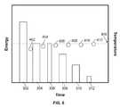
- FIG. 6illustrates a graph of energy delivery and temperature versus time
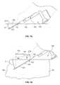
- FIG. 7Aillustrates a partial side view of probes entering tissue directly below a stabilization plate and oblique to a tissue engaging surface
- FIG. 7Billustrates a magnified view of the probes entering tissue at an oblique angle relative to the tissue engaging surface
- FIG. 7Cillustrates additional variations of devices and methods described herein using temperature sensors and/or additional energy transfer elements in the stabilization plate
- FIG. 7Dshows the use of one or more marking lumens
- FIG. 7Eshows another example of a probe entering tissue at an oblique angle underneath a skin anomaly
- FIGS. 8A to 8Cillustrates multiple sensors on electrodes/probes for measuring tissue parameters to adjust treatment parameters for improved therapeutic results or safety
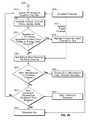
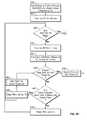
- FIGS. 9A to 9Gillustrate a safety net flow chart used with one variation of an RF generator according to the present system
- FIG. 10Aillustrates an example of a front view of an array of probes when entering the tissue at an angle relative to the surface such that the probes in the array vary in the depth at which they are inserted.
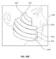
- FIG. 10Billustrates an example of a tissue characteristic indicator comprising visual or virtual depiction of the depth or location of the probe array of FIG. 10A ;
- FIGS. 10C and 10Dillustrates additional variations of tissue characteristic indicators that provide information regarding the probe array of FIG. 10 ;
- FIGS. 10E and 10Fshow examples of a graphical user interface (GUI);
- FIG. 10Gillustrates one example of sub-target regions identified on a GUI
- FIGS. 11A-11Dillustrate variations of electrodes having varying resistance or impedance along the length of the electrode
- FIG. 12Ais a perspective view of a variation of a device having an informational display located on a body unit of the system;
- FIG. 12Bis a top view of the device shown in FIG. 12A ;
- FIG. 13Ashows an example of a series of discrete focal lesions created in a reticular dermis
- FIG. 13Bshows the discrete focal lesions increasing in a width of the reticular dermis layer without damaging adjacent tissue
- FIG. 13Cshows an example of a lesion where the application of treatment via the electrode pairs avoids damage to adnexal structures in the reticular dermis.
- the systems and method discussed hereintreat tissue in the human body.
- the systems and methodstreat cosmetic conditions affecting the skin of various body parts, including face, neck, and other areas traditionally prone to wrinkling, lines, sagging and other distortions of the skin.
- the methods and systems described hereinmay also have application in other surgical fields apart from cosmetic applications.
- the inventive device and methodsalso include treatment of skin anomalies such as warts (Verruca plana, Verruca vulgaris), sebaceous hyperplasia or acne (Acne vulgaris).
- Treatment of acnecan be accomplished by the direct ablation of sebaceous glands or it can be accomplished by the delivery of thermal energy which will stimulate the body's immune system to eliminate the bacteria.
- Propionibacterium acneswhich is one of the causes of acne.
- the methods and devicescan be used for the removal of unwanted hair (i.e., depilation) by applying energy or heat to permanently damage hair follicles thereby removing the skills ability to grow hair.
- Such treatmentmay be applied on areas of facial skin as well as other areas of the body.
- pain managementboth in the use of heat to reduce pain in muscle tissue and by directly ablating nociceptive pain fibers
- stimulation of cellular healing cascade via heattreatment of the superficial muscular aponeurotic system (SMAS), reproductive control by elevated heating of the testicles, and body modification such as piercing, scarification or tattoo removal
- the current inventioncan be targeted to the underlying layer of adipose tissue or fat for lipolysis or the breakdown of fat cells.
- Selecting probes having sufficient length to reach the subcutaneous fat layerallows for such probes to apply energy in the subcutaneous fat layer.
- Application of the energycan break down the fat cells in that layer allowing the body to absorb the resulting free fatty acids into the blood stream.
- Such a processcan allow for contouring of the body surface for improved appearance.
- such an approachcan be used in the reduction of cellulite.
- pain managementboth in the use of heat to reduce pain in muscle tissue and by directly ablating nociceptive pain fibers
- stimulation of cellular healing cascade via heatreproductive control by elevated heating of the testicles, and body modification such as scarification.
- FIG. 1shows a cross sectional view of the skin 10 composed of an outer stratum corneum 15 covering the epidermis 16 .
- the skinalso includes the dermis 18 , subcutaneous tissue/fat 12 . These layers cover muscle tissue 14 of within the body.
- the skin 10measures about 2 mm in cross sectional depth.
- the epidermismeasures about 100 ⁇ m in cross sectional depth.
- the skin 10also includes a dermis 18 layer that contains a layer of vascular tissue. In the face and neck regions, the dermis 18 measures about 1900 ⁇ m in cross sectional depth.
- the dermis 18includes a papillary (tipper) layer and a 19 reticular (lower) layer. Most of the dermis 18 comprises collagen fibers. However, the dermis also includes various hair bulbs, sweat ducts, sebaceous glands and other glands. The subcutaneous tissue 12 region below the dermis 18 contains fat deposits as well as vessels and other tissue.
- the application of heat to the fibrous collagen structure in the dermis 18causes the collagen to dissociate and contract along its length. It is believed that such disassociation and contraction occur when the collagen is heated to about 65 degrees C.
- the contraction of collagen tissuecauses the dermis 18 to reduce in size, which has an observable tightening effect. As the collagen contracts, wrinkles, lines, and other distortions become less visible. As a result, the outward cosmetic appearance of the skin 10 improves. Furthermore, the eventual wound healing response may further cause additional collagen production. This latter effect may further serve to tighten and bulk up the skin 10 .
- Thermal energyis not the only method for treating collagen in the dermal layer to effect skin laxity and wrinkles. Mechanical disruption or cooling of tissue can also have a desirable therapeutic effect.
- the devices and methods described hereinare not limited to the percutaneous delivery of thermal energy, but also include the percutaneous delivery of mechanical energy or even reducing temperature of tissues beneath the epidermis (e.g., hypothermia effect on tissue).
- the treatment methods and devicecan also include the use of additives, medicines, bioactive substances, or other substances intended to create a therapeutic effect on their own or augment a therapeutic effect created by any one of the energy modalities discussed herein.
- autograph or allograph collagencan be delivered percutaneously to bulk up the dermal layer.
- Non-collagen fillerssuch as absorbable and non-absorbable polymers can also be delivered to increase the volume of the dermis and improve the surface appearance of the skin.
- Salinecan be delivered to provide a diffuse path for radio frequency current delivery or to add or remove thermal energy from the target tissue.
- anesthetic or numbing agentscan be delivered to reduce the patient's sensation of pain from the treatment.
- the agentcan be applied on the epidermal layer or can be injected into the dermal layer of the skin.
- Botulinum Toxin type ABotox®
- Botox®can also be delivered to the dermis or to the muscular layer below the dermis by further inserting the access probe 32 . The delivery of Botox® can temporarily paralyze the underlying musculature allowing for treatment of the target area with no muscle movement to move or disturb the treatment area.
- the delivery of the substances described abovecan occur using the same delivery devices that apply the energy based treatment. Alternatively, or in combination, a physician can administer such substances using a delivery means separate from the treatment devices.
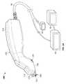
- FIG. 2Aillustrates one variation of a treatment system according the principles described herein.
- the treatment system 200generally includes a treatment unit 202 having a hand-piece or device body 210 (or other member/feature that allows for manipulation of the system to treat tissue 10 ) having one or more probes 104 extending from the body 210 .
- the probes 104are coupled to the body 210 via a removable cartridge 100 .
- the removable cartridge 100contains a plurality of retractable probes 104 arranged in an array 108 .
- probes 104(for purposes of this disclosure) is intended to include any electrode, energy transfer element (e.g., thermal, electrical, electromagnetic, microwave, mechanical, ultrasound, light, radiation, monopolar RF, bipolar RF, chemical, radioactive, etc.), or source of therapeutic treatment.
- energy transfer elemente.g., thermal, electrical, electromagnetic, microwave, mechanical, ultrasound, light, radiation, monopolar RF, bipolar RF, chemical, radioactive, etc.
- the term probeshall be used to refer to any electrode, energy transfer element or source of therapeutic treatment unless specifically noted otherwise.
- the probes 104can optionally extend from a front portion 112 of the cartridge 100 .
- the probes 104can extend from a front face of the device body or from any surface of the device body/cartridge.
- the device body 210 or the cartridge 100is not limited to that shown. Instead, variations include device body shapes that are thinner in profile and can be held at a more vertical angle to the target tissue like a pencil or pointer. Variations also include a device body that has a loop or curved grip that facilitates one specific manner in which it can be grasped by the hand. Any number of variations is possible especially those that ensure the physician's hand does not contact of the distal end of the cartridge or the target tissue.
- the devices according to the principles described hereincan include any number of arrays depending upon the intended treatment site. Currently, the size of the array, as well as the number of arrays, can change depending on the variation of the invention needed. In most cases, the target region of tissue drives the array configuration. The present invention allows a physician to selectively change array configuration by attaching different cartridges 100 . Alternatively, variations of the invention contemplate an probe assembly that is non-removable from the device body 200 .
- a treatment unit 202 designed for relatively small treatment areasmay only have a single pair of probes.
- a treatment unit 202 designed for use on the cheek or neckmay have tip to 10 probe pairs.
- estimates on the size of the probe arrayare for illustrative purposes only.
- the probes on any given arraymay be the same shape and profile.
- a single arraymay have probes of varying shapes, profiles, and/or sizes depending upon the intended application.
- the array 108 defined by the individual probes 104can have any number of shapes or profiles depending on the particular application. As described in additional detail herein, in those variations of the system 200 intended for skin resurfacing, the length of the probes 104 is generally selected so that the energy delivery occurs in the dermis layer of the skin 10 while the spacing of probes 104 may be selected to minimize delivery of energy between adjacent pairs of probes or to minimize energy to certain areas of tissue.
- the probes 104are resistive, radiofrequency, microwave, inductive, acoustic, or similar type of energy transfer elements
- the probescan be fabricated from any number of materials, e.g., from stainless steel, platinum, and other noble metals, or combinations thereof. Additionally, such probe may be placed on a non-conductive member (such as a polymeric member).
- the treatment unit 202may not include an actuator as described below for driving the probe array 108 from the cartridge 100 into the target region.
- actuatorsinclude, but are not limited to, pneumatic cylinders, springs, linear actuators, or other such motors.
- Alternative variations of the system 200include actuators driven by the control system/energy supply unit 90 .
- FIG. 2Aalso shows a stabilization plate 234 coupled to the device body 210 .
- the stabilization plate 214can serve several functions ranging from securing tissue flatly and in line with the tissue engaging surface 106 to providing cooling of the tissue directly normal to the application of energy.
- the stabilization plate 214can also provide a visual frame of reference for the physician prior to or during treatment.
- the stabilization plate 214holds tissue in front of the probe array 108 flat and in place. This prevents the tissue from “bunching” in front of the device and increases the likelihood that the array 108 are inserted a consistent depth within the tissue.
- the system 200also includes an energy supply unit 90 coupled to the treatment unit 202 via a cable 96 or other means.
- the system 200can also include additional components 94 such as an additional power supply unit that provides a different type of energy source.
- the energy supply unit 90contains the software and hardware required to control energy delivery.
- the CPU, software and other hardware control systemsmay reside in the hand piece 210 and/or cable 96 .
- the cable 96may be permanently affixed to the supply unit 90 and/or the treatment unit 202 .
- the hand piece 210can contain the controls alone or the controls and the power supply necessary to delivery treatment.
- the energy supply unit 90can include a graphical user interface 320 .
- the graphical user interface 320can provide information for a physician (or other medical staff) to monitor various treatment parameters as well as other information regarding the placement of the array 108 or probes 104 when inserted in the tissue or prior to a treatment cycle. By monitoring this information, the physician can increase the effectiveness of the treatment.
- one or more informational characteristics shown on the graphical user interface 320can be shown on a portion of the treatments device 202 so that the physician can maintain visual contact with the treatment device and tissue being treated.
- the graphical user interface 320can be located on multiple components or solely on the handpiece.
- the energy supply unit 90may be a RF energy unit. Additional variations of energy supply units may include power supplies to provide or remove thermal energy, to provide ultrasound energy, microwave energy, laser energy, pulsed light energy, and infrared energy. Furthermore, the systems may include combinations of such energy modalities.
- additional energy sources 90can be delivered via the same or additional energy transfer elements located at the working end of a treatment unit 202 .
- the radiant energymay be supplied by the energy source/supply 90 that is coupled to a diode, fiber, or other emitter at the distal end of the treatment unit 202 .
- the energy source/supply 94 and associated energy transfer elementmay comprise laser, light or other similar types of radiant energy (e.g., visible, ultraviolet, or infrared light).
- intense pulsed light having a wavelength between 300 and 12000 nmcan also be used in conjunction with RF current to heat a targeted tissue.
- Such associated transfer elementsmay comprise sources of light at the distal end of the treatment unit 202 . These transfer elements may be present on the cartridge 100 , on the device body 210 or even on the cooling unity 234 . More specifically a coherent light source or laser energy can be used in conjunction with RF to heat a targeted tissue. Examples of lasers that can be used include erbium fiber, CO 2 , diode, flashlamp pumped, Nd:YAG, dye, argon, ytterbium, and Er:YAG among others. More than one laser or light source can be used in combination with RF to further enhance the effect.
- a pulsed infra-red light sourcecan be used to heat the skin surface
- an Nd:YAG lasercan be used to heat specific chromophores or dark matter below the surface of the skin
- RF currentcan be applied to a specific layer within or below the skin; the combination of which provides the optimal results for skin tightening, acne treatment, lipolysis, wart removal or any combination of these treatments.
- Ultrasound energycan be delivered either through the RF probes, through a face plate on the surface of the skin, or through a separate device.
- the ultrasound energycan be used to thermally treat the targeted tissue and/or it can be used to sense the temperature of the tissue being heated.
- a larger pulse of pressurecan also be applied to the surface of the skin in addition to RF current to disrupt adipose tissue. Fat cells are larger and their membranes are not as strong as those of other tissue types so such a pulse can be generated to selectively destroy fat cells.
- the multiple focused pressure pulses or shock wavescan be directed at the target tissue to disrupt the cell membranes. Each individual pulse can have from 0.1 to 2.5 Joules of energy.
- the ultrasound energycould also be used for imaging purposes. For example, it could be used to assess the penetration depth of the electrodes, or to identify in which tissue layer the electrodes are located.
- the energy supply unit 90may also include an input/output (I/O) device that allows the physician to input control and processing variables, to enable the controller to generate appropriate command signals.
- the I/O devicecan also receive real time processing feedback information from one or more sensors associated with the device, for processing by the controller, e.g., to govern the application of energy and the delivery of processing fluid.
- the I/O devicemay also include a display, to graphically present processing information to the physician for viewing or analysis.
- the system 200may also include an auxiliary unit 92 (where the auxiliary unit may be a vacuum source, fluid source, ultrasound generator, medication source, a source of pressurized air or other gas, etc.) Although the auxiliary unit is shown to be connected to the energy supply, variations of the system 200 may include one or more auxiliary units 92 where each unit may be coupled to the power supply 90 and/or the treatment unit 202 .
- FIG. 2Billustrates a partial view of a working end of a treatment unit 202 where the treatment unit 202 engages against tissue 10 with the tissue engaging surface 106 as well as the stabilization surface 214 smoothing the tissue 106 beneath the device 200 to increase the uniformity of insertion depth of the array 108 . As shown, the array 108 can then be inserted into the tissue 10 when advanced from a cartridge 100 .
- the illustrated figurealso demonstrates another feature of the system where the system 200 includes a tissue engaging surface 106 (in this variation on a cartridge 100 having a plane that forms an angle A with a plane of the array of probes 108 .
- this configurationpermits a larger treatment area as well as direct cooling of the tissue surface.
- the devices of the present inventionmay have an angle A of 25 degrees. However, the angle can range from anywhere between perpendicular (90 degrees) to quasi-parallel (nearly zero degrees but still able to penetrate tissue) with respect to the tissue surface.
- the angle Ais typically chosen to increase the likelihood that an active portion of the probe will be inserted within a desired location in tissue. Accordingly, the depth of the target region, design of the hand piece, as well as a number of additional factors may require that the angle vary between nearly 0 and 90 degrees.
- the tissue engaging surface 106can also include any number of features to ensure adequate contact with tissue (such as increased frictional characteristics, sensors to ensure proper contact, etc.). It was observed that having a penetration angle of about 20 to about 25 degrees facilitated the insertion of the needles into the skin tissue layers when compared to a perpendicular penetration angle. Tensioning the skin at the insertion points further facilitated the penetration into tissue.
- the stabilization surface, in conjunction with the tissue engaging surface 106can also be used to hold and therefore tension the skin at the insertion points to facilitate the needle insertion in the skin.
- the tissue engagement surfacemay contain apertures or other features to allow improved engagement against tissue given the application of a vacuum.
- the medical practitionermay better gauge the depth of the treatment. For example, given the relatively small sectional regions of the epidermis, dermis, and subcutaneous tissue, if a device is placed over an uneven contour of tissue, one or more probes may be not be placed at the sufficient depth. Accordingly, application of energy in such a case may cause a burn on the epidermis. Therefore, drawing tissue to the tissue engaging surface of the device increases the likelihood of driving the probes to a uniform depth in the tissue.
- the tissue engagement surface 106can include small projections, barbs, or even an elastic resin to increase friction against the surface of tissue. These projections or features can grip or provide friction relative to the tissue in proximity of the target tissue. This grip or friction holds the tissue in place while the probes are inserted at an angle relative to the grip of the projections.
- the tissue engaging surfacecan include contact or proximity sensors to ensure that any numbers of points along the tissue engaging surface are touching the surface of the target site prior to probe deployment and/or energy delivery.
- FIG. 2Cshows a top view of the treatment unit 202 of FIG. 2B .
- the stabilization plate 214includes a feature 216 such as (a window or an opening) that permits a physician to directly observe insertion of the probe array 108 through the stabilization plate 214 .
- the stabilization plate 214can be fabricated to be transparent and the feature 216 can comprise a marking to outline the tissue region in which the probes will be inserted. Such features of the stabilization plate 214 are important when the probes are deployed into tissue subsequent to placement of the device body 210 against tissue. A physician can rely upon the stabilization plate 214 or the feature 216 as confirmation for the intended treatment are and avoid body structures where treatment would be undesirable.
- the stabilization plate 214 or feature 216permits the physician to situate the treatment unit 202 while avoiding the region in question.
- the outline of the feature 216 or the stabilization plate 214itself aligns (in a normal plane) with the distal end of the probe array 108 .
- the electrodes of the probe arraycan also include any number of visually distinguishing features (e.g., depth markings, colors, shades, etc.) that enable a physician to observe proper placement.
- a probecan be marked with a certain color that they physician should be able to see during treatment. This ensures that the probe is not driven too far into tissue.
- the probecan be marked with one or more features that allow the physician to determine the depth of insertion of the probe.
- the stabilization plate 214can also be designed to permit the physician with an outline of the extent of tissue being treated.
- the entire stabilization plate 214can be sized to have a profile to correspond to the area of tissue that will affected by the energy supplied to the tissue.
- the stabilization plate 214can have any number of projections, points, barbs, hooks, vacuum or fluid apertures to further stabilize tissue.
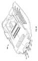
- FIG. 3Aillustrates a sectional view of a device body 210 to illustrate placement of an actuator 250 and a cooling device 234 within the device body 210 .
- FIG. 3Aillustrates a sectional view of a device body 210 to illustrate placement of an actuator 250 and a cooling device 234 within the device body 210 .
- some of the components of the device body 210are omitted.
- the system 200can include an actuator 250 within the device body 210 that can be coupled to an array of probes in a mating receiving surface (discussed below) to drive the probes into tissue.
- the actuator 250can be coupled to the array at a distal end of a shaft 252 in any commonly known manner.
- the actuator 250comprises a motor or drive unit that provides sufficient force, speed or impact to the probes to drive them into tissue.
- the actuator 250can be spring loaded to deliver sufficient force, speed or impact to allow penetration of the probe array into tissue.
- the actuatormay comprise any number of actuation means, including, but not limited to, pneumatic cylinders, springs, linear actuators, or other such motors.
- FIG. 2Dshows the treatment system 202 of FIG. 2A where the cartridge assembly 100 and device body 210 are separated.
- the cartridge body 100 and device body 210can be a single non-detachable structure.
- a single device body 210can be used with a variety of cartridge assemblies here each cartridge assembly is specifically configured depending upon the desired application.
- the cartridge assembly 100places the probes 104 in an array 108 and at a specific orientation relative to a tissue engaging surface 106 .
- the cartridge 100can also be configured to provide the probes 104 on a probe assembly 102 that is slidable relative to the cartridge body 100 and device body 210 such that the probes 104 can be driven into tissue as further discussed below.
- FIG. 3Aalso illustrates a cooling device 234 for use with tile systems described herein.
- the cooling device 234is fitted within the handle 202 and coupled to the stabilization plate 214 .
- the cooling device 234maintains a surface of the tissue being treated at a desired temperature.
- the stabilization plate 214serves multiple functions (to maintain tissue parallel to the tissue engaging surface 106 , to provide a visual boundary for the treatment, and to provide cooling of tissue immediately normal to the treatment region).
- FIG. 3Billustrates a side view of the device body 210 from FIG. 3A .
- this particular variation of a cooling device 234permits transfer of heat from a first conduction plate 236 to a second conduction plate 238 via thermal heat pipes 240 .
- Such a configurationpermits the first conduction plate 236 to draw heat from the stabilization plate 214 .
- the heat pipes 240draw heat away from the first conduction plate 236 towards the second conduction plate 238 , which is cooled via a heat sink 240 .
- the device body 210can include any number of cooling means (such as fans, fluid sources, etc.) to reduce a temperature of the heat sink 240 .
- FIG. 3Cshows an isometric view of only a cooling device 234 coupled to a stabilization plate 214 .
- the use of heat pipes 240enables heat to be transported away from the stabilization plate 214 and to a heat sink 242 .
- Such a featureeliminates the need to place the cooling device 234 or portions thereof over the stabilization plate 214 .
- This configurationpermits a physician to have unobstructed view of the stabilization surface 214 since the cooling device 234 can be distributed over the length of the handle.
- the cooling device 234can be coupled to a cooling engine (e.g., a source of cooling fluid, a fan, and/or a Peltier device) to assist in maintaining the stabilization plate at a desired temperature.
- a cooling engine 244can be placed between the first conduction plate 236 and the stabilization plate 214 to maintain the stabilization plate 214 at the desired temperature while the first conducting plate 236 draws heat.
- the cooling engine 244can be coupled to a cooling supply 246 .
- the cooling supplycan be a power supply for a thermo-electric cooling engine.
- the cooling supply 246can circulate fluid within a cooling engine.
- the cooling devicecan be an air or liquid type cooling device.
- the cooling devicecan include a Peltier cooling device, which can eliminate the need for a fluid source.
- the cooling, devicecan be powered using the same power supply that energizes the probes. Such a configuration provides a more compact design that is easier for a medical practitioner to manipulate.
- FIG. 3Dshows a cross sectional view of a heat pipe 240 for use with the cooling systems described herein.
- the heat pipe 240is comprised of an outer casing 280 comprised of a thermally conductive material such as aluminum, stainless steel, copper, silver, gold, etc.
- the casingencloses a wick material 282 that defines a chamber 284 .
- a thermally conductive fluid(e.g., water, alcohol, ammonia. etc.) circulates within the heat pipe 240 .
- a hot end 286 of the heat pipe 240conducts thermal energy through the casing 280 to the fluid in the wick 282 .
- the fluidevaporates (as denoted by arrow a) from the wick into the chamber 284 .
- Step Bthe vapor migrates (as denoted by arrow b) through the chamber 284 to the cold end 288 of the heat pipe 240 .
- step Cthe vapor condenses (as denoted by arrow c) and is absorbed into the wick completing the thermal energy transfer.
- step Dthe fluid is transported (as denoted by arrow d) through the wick 282 back to the hot end 286 of the heat pipe 240 while the thermal energy is conducted out of the casing 280 .
- a cooling engine 244can be coupled to the second conduction plate 238 to provide a smaller profile towards the stabilization plate 214 .
- the cooling engine 244can take the place of the cooling pipes 240 as well as the first and second conduction plates 236 , 238 .
- FIG. 4Aillustrates one variation of a cartridge body 100 for use with variations of the present system.
- the cartridge body 100includes retention fasteners 114 allowing for coupling with the device body as well as removal from the device body.
- retention fasteners 114allowing for coupling with the device body as well as removal from the device body.
- any number of structurescan be incorporated into the device to permit removable coupling of the cartridge body 100 to a treatment unit.
- the cartridge body 100further includes an electrode assembly 102 that is moveable or slidable within the cartridge body 100 .
- the mode of movement of the actuatorcan include those modes that are used in such similar applications. Examples of these modes include, sliding, rotation, incremental indexing (via a ratchet-type system), stepping (via an step-motor)
- the electrode assembly 102can include a coupling portion or structure 118 that mates with an actuating member in the device body.
- the electrode assembly 102is in a treatment position (e.g., the array 108 extends from the cartridge 100 allowing for treatment).
- the electrode assembly 102includes any number of electrodes 104 that form an array 108 and are extendable and retractable from a portion 104 of the cartridge 100 (as noted above, the electrodes can alternatively extend from the device body, or other parts of the system). As noted above, although the illustrated example shows an array 108 of 1 ⁇ 6 electrodes 104 , the array can comprise any dimension of M ⁇ N electrodes where the limits are driven by the nature of the treatment site as well as the type of energy delivery required.
- FIG. 4Aalso shows the electrodes 104 in the electrode assembly 102 as having connection or contact portions 116 that couple to a connection board on a treatment unit to provide an electrical pathway from the power supply to the electrodes 104 .
- the electrode assembly 102as well as the connection portions 116 moves.
- Such a featureallows for selective connection of the electrodes with the power supply.
- the electrodesare only coupled to the power supply when in a treatment position and are incapable of delivering energy when in a retracted position.
- the electrode assembly and connection boardare configured to permit temperature detection at all times but only energy delivery in the treatment position.
- Such customizationcan prevent energy delivery in an unintended location, for example, when the electrodes have an insulation that only allows energy delivery at the distal tip and the intended location of energy delivery is at specific depth in the target tissue that corresponds to the length of the extended electrode the electrode cannot delivery energy to an unintended shallower location when it is not fully extended.
- the systemcan be configured so that the electrodes can be energized whether in the treatment or retracted positions.
- connection portions 116can be fabricated in any number of configurations as well.
- the connection portions 116comprise spring contacts or spring pins of the type shown. Accordingly, the connection portions 116 can maintain contact with a corresponding contact point trace on a connection board during movement of the electrode assembly 102
- FIG. 4Aalso shows a front portion 112 of the cartridge 100 as having multiple guiding channels 120 .
- These channels 120can support and guide the electrode 104 as they advance and retract relative to the cartridge 100 .
- the channels 120can also be configured to provide alternate energy treatments to the surface of the tissue as well as suction or other fluids as may be required by a procedure.
- One benefitis that a single cartridge design can be configured to support a variety of electrode array configurations. For example rather than the array of six (6) electrodes as shown, the channels 120 can support any number of electrodes (the illustrated example shows a maximum of sixteen (16) but such a number is for exemplary purposes only).
- the channels 120need not be only in a linear arrangement as shown, but could be in 1, 2, 3 or more rows or in a random configuration.
- the electrodescan be designed to intentionally “over-insert” and then slightly retract prior to initiating the treatment. This feature allows for improved consistency of complete insertion. The skin can move away on insertion if the skin is not taught resulting in partially inserted electrodes. Over inserting and then partially retracting the electrodes compensates for the movement and laxity of the skin resulting in a more reliable insertion.
- FIG. 4Bshows another variation of a cartridge 100 .
- the retention fasteners 114 of the cartridge 100differ from those shown in FIG. 4A .
- any number of connection fastener configurationscan be used with various cartridge assemblies of the present invention.
- FIG. 4Balso shows a variation where a connector assembly 101 containing connection portions 116 , 117 is separated from the electrode assembly 102 .
- any type of electrical connection 132 , 134can be used to couple the connecting assembly 101 to the electrode assembly 102 .
- wires, ribbons, etc.can be used.
- This configurationpermits the connection portions 116 , 117 to remain stationary while the electrode assembly 102 and probes 104 are slidable within the cartridge 100 .
- the cartridge 100includes a coupling portion 118 to couple the probe assembly to the actuator as discussed below.
- FIG. 4Cillustrates a variation of a cartridge body 100 when the electrode assembly 102 is in a retracted position.
- the connection portions 116 , 117 of the electrodes 104can extend from a top of the electrode assembly 102 .
- the electrode assembly 102can also optionally include a coupling body 118 to engage an actuator on the treatment device.
- the electrode assembly 102can have multiple connection portions 116 , 117 per individual electrode.
- the multiple connection portions 116 and 117can be electrically insulated from one another to increase the number of configurations possible with the electrode assembly.
- the proximal connection portion 116can electrically couple to a temperature detecting circuit on the hand unit.
- the distal connection portion 117can connect to a power delivery circuit only upon distal advancement of the needle assembly 102 . In such an example, the temperature of the electrodes can be continuously monitored while the power delivery to the electrodes can be limited to distal advancement of the assembly.
- FIG. 4Calso shows an example of an electronic memory unit 115 , as noted above.
- the memory unitcan provide the system with memory capabilities for containing instructions or record communication between the cartridge and hand unit and/or controller to adjust treatment parameters, monitor usage, monitor sterility, or to record and convey other system or patient characteristics.
- the unit 115can also be an RFID antenna or receiver.
- FIG. 4Dshows a perspective view of another variation of an electrode assembly.
- the electrodes 104are staggered or offset such that adjacent electrode pairs 105 do not form a linear pattern.
- One such benefit of this configurationis to overcome the creation of a “line effect” in tissue.
- an array of electrodes arranged in a single linecan possibly result in a visible line in tissue defined by the entry points of adjacent and parallel electrodes.
- staggering or offsettingthe electrodes prevents the “line effect” from occurring.
- FIG. 4Eshows a side view of the variation of FIG. 4D .
- the electrodes 104are offset to minimize the chance of forming a single continuous line in tissue by penetration of a set of linearly arranged electrodes and therefore maintaining the focal and fractional aspect of the created lesions, as further explained in FIGS. 11A and 11C later in this document.
- other configurationcan also address the “line effect”. For example, the spacing between adjacent electrodes can be increased to minimize a “line effect” but to still permit efficacy of treatment.
- variations of the deviceinclude electrodes 104 that form more than two rows of electrodes.
- FIG. 4Fshows a top view of the cartridge variation of FIG. 4D .
- the variation illustratedshows that the plurality of electrodes comprises a plurality of electrode pairs 105 .
- the electrode pairs 105can be vertically offset from an adjacent electrode pair (as shown in FIG. 4E ) so that insertion of electrode pairs into the tissue does not create a continuous line of insertion points.
- the electrodes 104can be axially offset (such that an end of the electrode) extends a greater distance than an end of an adjacent electrode or electrode pair.
- axially offsetting the electrodesallows for a uniform insertion depth when measured relative to a tissue engaging surface of the cartridge.
- each electrode pair 105can include an active and return electrode 104 to contain current flow between electrodes in an electrode pair 105 .
- additional configurationsare within the scope of the device.
- adjacent electrode pairscan serve as opposite poles of a circuit or the electrodes can be monopolar where the therapeutic effect is controlled by selective firing of electrodes.
- the systemcan be provided with a number of electrode cartridges where the spacing or offset of the electrodes varies and allows for the physician to control treatment or placement of the electrodes by exchanging cartridges.
- each electrode pairmay include a thermocouple to separately monitor each treatment site; the duration of the energy treatment may be controlled depending on the characteristics of the surrounding tissue; selective electrode pairs may be fired rather than all of the electrode pairs firing at once (e.g., by firing electrode pairs that are located on opposite ends of the electrode plate one can further minimize the chance that a significant amount of current flows between the separate electrode pairs.)
- a number of additional configurationsare also available depending on the application. Additional variations of the device may include electrode pairs that are coupled to a single channel of a power supply as well.
- FIG. 5illustrates a cross sectional view of a distal end of a variation of treatment unit 202 without a cartridge attached to a cartridge receiving surface 254 of the device body 210 .
- the device body 210includes a moveable actuator 250 adjacent to the cartridge receiving surface 254 .
- a shaft 256 of the actuator 250couples to a cartridge or probe assembly on a cartridge.
- the actuator 250moves the shaft 256 where an engagement portion 252 on the shaft couples to the probe assembly (e.g., via a coupling portion 118 shown above) to advance and retract the probes (not shown).
- the actuatorcan comprise a spring mechanism (not shown) such that it may be spring loaded to deliver sufficient force to cause penetration of a probe array into tissue.
- the actuatormay comprise any number of actuation means, including, but not limited to, pneumatic cylinders, springs, linear actuators, or other such motors.
- the present systemsmay apply treatments based upon sensing tissue temperature conditions as a form of active process feedback control.
- those systems relying oil conduction of energy through the tissuecan monitor changes in impedance of the tissue being treated and ultimately stop the treatment when a desired value is obtained, or stop the treatment when a maximum allowable impedance value is reached.
- the delivery of energycan depend on whether impedance is within a certain range. Such impedance monitoring can occur before, during, or in between energy delivery and attenuate power if the dynamically measured impedance starts to exceed a given value or if the rate of increase is undesirably high.
- Yet another mode of energy deliveryis to provide a total maximum energy over a duration of time.
- Still another modeis to provide a maximum output power to limit the power delivery during the application in order to stay within a safe and effective energy delivery mode.
- the controllercan adjust the maximum parameters (maximum voltage, maximum current, maximum power, maximum impedance, maximum applied energy), and/or target parameters such as the target temperature or the time at target temperature based on the location of where the energy application is being performed.
- energy application and/or parametersmay vary when the treatment is applied to a face as opposed to a neck of a patient.
- such parameters and/or energywill vary depending on the anatomy of the target tissue (e.g., thicker or thicker tissue, presence of blood vessels, etc.) as well as the therapeutic effect desired.
- each probemay include a sensor or a sensor can be placed on a probe-like structure that advances into the tissue but does not function as an energy delivery probe.
- the sensorsmay be a vertically stacked array (i.e. along the length of the probe) of sensors to provide data along a depth or length of tissue.
- systems according to the present inventionare able to provide a desirable effect in the target area though they use a relatively low amount of energy when compared to systems that treat through the epidermis. Accordingly, systems of the present invention can apply energy in various modes to improve the desired effect at the target area.
- the systemcan simply monitor the amount of energy being applied to the target site. This process involves applying energy and maintaining that energy at a certain pre-determined level. This treatment can be based on a total amount of energy applied and/or application of a specific amount of energy over a set period of time. In addition, the system can measure a temperature of the target site during the treatment cycle and hold that temperature for a pre-determined amount of time. However, in each of these situations, the system does not separate the time or amount of energy required to place the target site in the desired state from the time or amount of energy required to hold the target site in the desired state.
- the time or amount of energy used to place the target in a desired stateis included in the total treatment cycle.
- the systemcan maintain a temperature of the target site at a pre-determined treatment temperature during a pre-determined cycle or dwell time. The system then delivers energy to maintain the target site at the treatment temperature. Once the target site reaches the treatment temperature, the system then maintains this condition for the cycle or dwell time.
- This variationallows for precise control in maintaining the target site at the pre-determined temperature.
- the systemcan monitor the amount of power applied to the target site for a specific dwell time. By continuously measuring current and output voltage, the system can calculate both the impedance changes and the delivered power levels. With this method a specific amount of power can be delivered to the target tissue for a specified amount of time.
- the above variationscan be combined with various methods to control time, temperature or energy parameters to place the tissue in the desired state.
- the systemcan employ a specified ramp time or maximum energy to achieve the pre-determined treatment temperature.
- Such a variationcan create a faster or slower ramp to the treatment temperature.
- the mere act of inserting the probe array into tissuecan also yield therapeutic benefits.
- the mechanical damage caused by placement of the probesalso produces an adjunct healing response.
- the healing response to injury in the skin tissuecan contribute to the production of new collagen (collagenesis) that can further improve the tone or appearance of the skin.
- a medical practitionermay opt to use the methods and systems to create mechanical injury to tissue by placing probes into target areas without thermal treatment to induce a healing response in the targeted area.
- the inventionis not limited to application of energy via the probes.
- the low energy requirements of the systempresent an additional advantage since the components on the system undergo less stress than those systems needing higher amounts of energy.
- RF energyis often delivered in a pulsed fashion or for a specific duty cycle to prevent stressing the components of that system.
- the reduced energy requirements of the present systemallow for continual delivery of RF energy during a treatment cycle.
- the duty cycle of variations of the present systemcan be pulsed so that temperature measurements can be taken between the pulsed deliveries of energy. Pulsing, the energy delivery allows for an improved temperature measurement in the period between energy deliveries and provides precise control of energy delivery when the goal of the energy delivery is to reach a pre-determined temperature for a pre-determined time.
- FIG. 6illustrates a graph of energy delivery and temperature versus time.
- the pulses or cycles of energyare represented by the bars 302 , 304 , 306 , 308 , 310 , 312 .
- Each pulsehas a parameter, including amount of energy, duration, maximum energy delivered, energy wave form or profile (square wave, sinusoidal, triangular, etc), current, voltage, amplitude, frequency, etc.
- measurementsare taken between pulses of energy. Accordingly, between each pulse of energy delivery one or more temperature sensor(s) near the probe obtains a temperature measurement 402 , 404 , 406 , 408 , 410 , 412 .
- the controllercompares the measured temperature to a desired temperature (illustrated by 400 ).
- the energy parametersare adjusted for the subsequent energy pulse. Measuring temperature between pulses of energy allows for a temperature measurement that is generally more accurate than measuring during the energy delivery pulse. Moreover, measuring between pulses allows for minimizing the amount of energy applied obtaining the desired temperature at the target region.
- the probesmeasure parameters of the tissue.
- the systemthen applies energy to accommodate the parameters.
- the probescan measure impedance of the surrounding tissue.
- the control systemcan then adjust an amount or a rare of energy depending upon the measured value.
- the system 200can extend a probe at an oblique angle relative to a tissue engagement surface 106 .
- the ability to insert the probes into the tissue at an oblique angleincreases the treatment area and allows for improved cooling at the tissue surface (directly above or in a direction normal to the probes).
- variations of the inventionmay include multiple arrays of probes.
- the devices of the present inventionmay have an angle A of 20 degrees. However, the angle may be anywhere from ranging between 5 and 85 degrees (or as otherwise noted herein).
- FIG. 7Aillustrates a partial side view of the probes 104 and tissue engaging surface 106 .
- the probes 104are advanceable from the device body 210 on a cartridge 100 having a probe assembly 102 .
- the probesenter tissue at an oblique angle A as measured relative to the tissue engagement surface 106 or stabilization plate 214 .
- the tissue engagement surface 106allows a user to place the device on the surface of tissue and advance the probes 104 to the desired depth of tissue. Because the tissue engagement surface 106 provides a consistent starting, point for the probes, as the probes 104 advance from the device 202 they are driven to a uniform depth in the tissue.
- the probe 104may be advanced too far or may not be advanced far enough such that they would partially extend out of the skin. As discussed above, either case presents undesirable outcomes when attempting to treat the dermis layer for cosmetic effects. In eases where the device is used for tumor ablation, inaccurate placement may result in insufficient treatment of the target area.
- FIG. 7Billustrates a magnified view of the probes 104 entering tissue 20 at an oblique angle A with the tissue engaging surface 106 resting on the surface of the tissue 20 .
- the probe 104can include an active area 122 .
- the term “active area”refers to the part of the probe through which energy is transferred to or from the tissue.
- the active areacould be a conductive portion of a probe, it can be a resistively heated portion of the probe, or even comprise a window through which energy transmits to the tissue.
- this variationshows the active area 122 as extending over a portion of the probe, variations of the device include probes 104 having larger or smaller active areas 122 .
- the resulting lateral region of treatment 152corresponding to the active area 122 of the probe is larger than if the needle were driven perpendicular to the tissue surface.
- This configurationpermits a larger treatment area with fewer probes 104 .
- the margin for error of locating the active region 122 in the desired tissue regionis greater since the length of the desired tissue region is greater at angle A than if the probe were deployed perpendicularly to the tissue.
- the probes 104may be inserted into the tissue in either a single motion where penetration of the tissue and advancement into the tissue are part of the same movement or act.
- variationsinclude the use of a spring mechanism or impact mechanism to drive the probes 104 into the tissue. Driving the probes 104 with such a spring-force increases the momentum of the probes as they approach tissue and facilitates improved penetration into the tissue.
- variations of the devices discussed hereinmay be fabricated to provide for a dual action to insert the probes.
- the first actionmay comprise use of a spring or impact mechanism to initially drive the probes to simply penetrate the tissue.
- Use of the spring force or impact mechanism to drive the probesmay overcome the initial resistance in puncturing the tissue.
- the next actionwould then be an advancement of the probes so that they reach their intended target site.
- the impact mechanismmay be spring driven, fluid driven or via other means known by those skilled in the art.
- One possible configurationis to use an impact or spring mechanism to fully drive the probes to their intended depth.
- Inserting the probe at angle Aalso allows for direct cooling of the surface tissue.
- the area of tissue on the surface 156 that is directly adjacent or above the treated region 152i.e., the region treated by the active area 122 of the probe 104
- This gap 154allows for direct cooling of the entire surface 156 adjacent to the treated region 152 without interference by the probe or the probe mounting structure.
- coolingmust occur at or around the perpendicular entry point.
- the probe 104enters at an oblique angle A such that the active region 122 of the probe 104 is directly adjacent or below the cooling surface (in this case the stabilization plate 214 ).
- the cooling surface 216may extend to the entry point (or beyond) of the probe 104 .
- devices and methods described hereinmay also incorporate a cooling source in the tissue engagement surface.
- the cooling surface/stabilization plate 214 and cooling device coupled theretocan be any cooling mechanism known by those skilled in the art.
- itmay be a manifold type block having liquid or gas flowing through for convective cooling.
- the cooling surface 214may be cooled by a thermoelectric cooling device (such as a fan or a Peltier-type cooling device).
- the coolingmay be driven by energy from the probe device thus eliminating the need for additional fluid supplies.
- a deviceincludes a cooling surface 214 having a temperature detector 218 (thermocouple, RTD, optical measurement, or other such temperature measurement device) placed within the cooling surface.
- the devicemay have one or more temperature detectors 218 placed anywhere throughout the cooling surface 216 or even at the surface that contacts the tissue.
- the cooling surface 214is maintained at or near body temperature. Accordingly, as the energy transfer occurs causing the temperature of the surface 156 to increase, contact between the cooling surface 214 and the tissue 20 shall cause the cooling surface to increase in temperature as the interface reaches a temperature equilibrium. Accordingly, as the device's control system senses an increase in temperature of the cooling surface 214 additional cooling can be applied thereto via increased fluid flow or increased energy supplied to a Peltier-type device. The cooling surface can also pre-cool the skin and underlying epidermis prior to delivering the therapeutic treatment.
- the cooling surfacecan cool the surface and underlying, epidermis during and/or subsequent to the energy delivery where such cooling is intended to maintain the epidermis at a specific temperature below that of the treatment temperature.
- the epidermiscan be kept at 30 degrees C. when the target tissue is raised to 65 degrees C.
- the dermisWhen treating the skin, it is believed that the dermis should be heated to a predetermined temperature condition, at or about 65 degree C., without increasing the temperature of the epidermis beyond 42 degrees C. Since the active area of the probe designed to remain beneath the epidermis, the present system applies energy to the dermis in a targeted, selective fashion, to dissociate and contract collagen tissue. By attempting to limit energy delivery to the dermis, the configuration of the present system also minimizes damage to the epidermis.
- cooling surfacemay comprise any commonly known thermally conductive material, metal, or compound (e.g., copper, steel, aluminum, etc.). Variations of the devices described herein may incorporate a translucent or even transparent cooling surface. In such cases, the cooling device will be situated so that it does not obscure a view of the surface tissue above the region of treatment.
- the cooling surfacecan include a single crystal aluminum oxide (Al 2 O 3 ).
- the benefit of the single crystal aluminum oxideis a high thermal conductivity optical clarity, ability to withstand a large temperature range, and the ability to fabricate the single crystal aluminum oxide into various shapes.
- a number of other optically transparent or translucent substancescould be used as well (e.g., diamond, other crystals or glass).
- FIG. 7Cillustrates another aspect for use with variations of the devices and methods described herein.
- the cartridge 100includes two-arrays of probes 104 , 126 .
- the first plurality 104is spaced evenly apart from and parallel to the second plurality 126 of probes.
- the first set of probes 104has a first length while the second set of probes 126 has a second length, where the length of each probe is chosen such that the sets of probes 104 , 126 extend into the tissue 20 by the same vertical distance or length 158 .
- variations of the inventioninclude any number of arrays as required by the particular application.
- the lengths of the probes 104 , 126are the same. However, the probes will be inserted or advanced by different amounts so that their active regions penetrate a uniform amount into the tissue. As shown, the cooling surface may include more than one temperature detecting element 218 .
- FIG. 7Calso illustrates a cooling surface/stabilization plate 214 located above the active regions 122 of the probes.
- FIG. 7Calso shows a variation of the device having additional energy transfer elements 105 located in the cooling surface 216 .
- these energy transfer elementscan include sources of radiant energy that can be applied either prior to the cooling surface contacting the skin, during energy treatment or cooling, or after energy treatment.
- FIG. 7Dshows an aspect for use with methods and devices of the invention that allows marking of the treatment site.
- the cartridge 100may include one or more marking lumens 226 , 230 that are coupled to a marking ink 98 .
- marking lumen 226may be placed proximate to the probe 104 .
- markingmay occur at or near the cooling surface 216 since the cooling surface is directly above the treated region of tissue.
- the marking lumensmay be combined with or replaced by marking pads.
- any type of medically approved dyemay be used to mark.
- the dyemay comprise a substance that is visible under certain wavelengths of light. Naturally, such a feature permits marking, and visualization by the practitioner given illumination by the proper light source but prevents the patient from seeing the dye subsequent to the treatment.
- FIG. 7Eillustrates an example of the benefit of oblique entry when the device is used to treat the dermis 18 .
- the length of the dermis 18 along the active region 122is greater than a depth of the dermis 18 . Accordingly, when trying to insert the probe in a perpendicular manner, the shorter depth provides less of a margin for error when trying to selectively treat the dermis region 18 .
- the device and methodsmay be used to affect skin anomalies 153 such as acne, arts, sebaceous glands, tattoos, or other structures or blemishes.
- the probemay be inserted to apply energy to a tumor, a hair follicle, a fat layer, adipose tissue, SMAS, a nerve or a pain fiber or a blood vessel.
- the stabilization plate(not shown) can either include an opening to accommodate the anomaly 153 or can be made of a flexible material to conform to the anomaly 153 .
- FIG. 8Aillustrates another aspect for use with the systems and methods described herein.
- the systemis able to precisely deliver energy to target tissue for optimal therapeutic results. More specifically, this feature allows automated target tissue parameter measurement and uses that measurement to automatically enable and control energy delivered to the target tissue to optimize the desired effect of the energy on the tissue.
- tissue properties or parametersinclude, but are not limited to: electrical impedance, the phase angle of the electrical impedance, acoustic impedance, hydration, moisture content, electromagnetic reflectance/absorption, temperature, movement, and elasticity. Measurement, of these parameters provides specific information such as the type of tissue, tissue health, tissue depth and location of sensing/treatment cannula relative to tissue surface or relative to target and non-target tissues, potential response of tissue to subsequent treatment, or actual response of tissue to the present or previous treatments.
- FIG. 8Ashowing a partial section of a probe 108 placed in tissue 20
- the target tissueis shown as a third layer 8 .
- the probe 108must cross two different layers or types of tissue 4 , 6 .
- the probe 8contains a sensor 110 near a distal end or on an active area 122 of the probe 108 .
- the entire active area 122 of the probecan function as a sensor.
- Measurementof a tissue parameter by the sensor 110 provides information that can confirm whether the probe 108 is located in the desired target region. For example, when measuring impedance of the tissue, if the measured impedance is not within a range normally associated with tissue, the system can prevent treatment and alert the user for the need to reposition the probe 108 . Accordingly, the probe 108 can ultimately be repositioned as shown in FIG. 8B (or the active area 122 of the probe 108 can be repositioned).
- the probe 108can employ an RF energy mode to denature or coagulate collagen in a dermal layer.
- the probe 108can be used separately from the active region 122 , or the active region 122 can function as a sensor. In either case, the probe applies a very low level of current to the tissue to measure the tissue's impedance.
- the epidermis tissue layercomprises a very high impedance.
- the papillary epidermis layerhas relatively low impedance (150-250 Ohms).
- the reticular layerhas impedance in the range of 250 to 2000 Ohms.
- Below the dermislies a subcutaneous adipose layer that has high impedance (2500 to 5000 Ohms).
- tissue adjacent to each probecan measure and energy can be applied only to those probes that are properly placed. Additionally, certain tissue structures including vessels and sebaceous glands within the dermal layer may be identified by the properties discussed herein. Probes in an array that are spaced sufficiently close will measure the impedance of the immediate structure rather than the surrounding dermal tissue. This information can be provided to the user for placement adjustment, or used to directly to prevent or adjust treatment for that cannula electrode pair.
- the probecan employ light at two wave lengths 650 nm and 805 nm from a light source into the adjacent tissue.
- the lightis partially absorbed and partially reflected based on the amount of hemoglobin in red blood cells in the adjacent tissue.
- the reflected lightis captured by a fiber optics placed in or near the probe and directed to a detector which provides a reading to the energy controller. This reading can be used to stop energy delivery when the red blood cells in the adjacent tissue have been coagulated (the desired treatment end point) and as a result the light reflection reading has changed.
- FIG. 8Cillustrates another variation of a probe configuration.
- the probe 108comprises several sensors 110 .
- the probe 108is shown crossing varying layers or types of tissue 4 , 6 , and 8 .
- the spaced sensors 110permit the use to verify that the active region 122 of the probe 108 , is located substantially in the target tissue (in this example, region 8 and the other portion of the probe 108 are located substantially in non-target tissues layers 4 and 6 .
- the measured tissue parametersdo not have to be provided to the user for the user to make adjustment to the tissue treatment.
- the parametersmaybe used to automatically adjust treatment in any manner of ways with the use as part of the invention of a controller to read the parameters and adjust treatment.
- an RF delivery device having ten probe-electrodeswas configured to deliver energy via 5 independent and electrically isolated probe-electrode pairs.
- the devicewas coupled to a controller comprising a bi-polar RF generator having 5 independent channels.
- the configuration of the electrodeswas as described above (e.g., oblique insertion, cooling at a tissue surface, etc). Once the electrodes were placed in the tissue, a small level of current was independently delivered to each of the 5 bi-polar pairs to measure the impedance between the each of the electrodes in the pair. When the impedance of a pair was within a predetermined level the controller directed delivery of RF treatment current to that pair.
- the systemcan further incorporate a variety of control algorithms to control the power applied to the treated tissue based on any number of criteria. In one variation, it was found that maintaining the temperature at a pre-determined value and monitoring impedance of tissue resulted in a significant increased treatment effect while minimizing collateral damage to tissue.
- the systemmonitors the initial impedance of the tissue and uses an algorithm including a PID (Proportional, Integral, Derivative) control which controls the input voltage between a pair of electrode.
- PIDProportional, Integral, Derivative
- Vcontrol voltage
- T setis the set point temperature
- T measuredis the measured temperature.
- This control systemfirst compares the actual electrode temperature T measured (or temperature of the damaged tissue) to the set point temperature T set . If the two temperatures are very far apart then the system delivers a proportionally higher voltage. If temperatures relatively close, then the system gradually increases the voltage.
- the proportional increase in voltageis based on the k p coefficient that applies to the proportional aspect in the PID equation (the first term in the above equation).
- the PIDalso monitors the “rate of change” (derivative) between the measured temperature T measured and the set point temperature T set .
- a change to the k d coefficientimpacts the rate at which the system increases voltage. In other words, a voltage is applied, a temperature is measured, and the system increases the voltage to try to get the temperature up to the set point.
- Thisrelates to the third term in the above equation.
- a relatively small k d coefficientis used in order to make sure that control variable, V in this case, is not too sensitive to the noise.
- the same logicapplies to the integral (change in area “under the curve”) coefficient.
- the systemconstantly monitor the difference between the set and measured temperature and adjusts the input voltage accordingly until a steady state is achieved.
- the steady state conditionthere is no difference between the set and measured temperature.
- the only non-zero term of the above equationis the integral part (the third term).
- the input voltage Vis kept the constant, which keeps the measured temperature T measured equal to the set temperature T set . If something changes in the overall system, the controller will detect a variation in temperature difference and readjust the input voltage to bring the measured temperature back to the set point.
- an independent PID controlleralong with at least one independent temperature sensor, would be associated with only one pair of electrodes, which is electrically isolated from the other pair(s) of electrodes. Therefore, applying a current an electrically isolated pair of electrodes creates a fractional lesion confined within the exposed part of the electrode (as shown in FIG. 11A ). In other words, since all channels are electrically isolated, the current passing between each electrode of an electrically isolated pair will not be coupled to another electrode of another electrically isolated pair. Controlling the current flow in this manner allows for creation of a lesion along the entire length of the active area of the electrode and confined between electrodes of the pair.
- This treatmentcan also limit the lesion to the whole layer of tissue, or a substantial part of the tissue layer such as, for example, the dermal layer. Creation of lesion confined to a layer is typically not possible when only the distal end of the probe is the source of current flow.
- the initial energy applied to the electrode pair in each pair in the arrayis under a very low voltage and with a loose current. This allows measurement of the initial impedance. If the initial impedance is low (e.g., 250-700 ohms) the system applies a first set of PID coefficients. If the system measures moderate impedance, the system applies a second set of PID coefficients. If the system measures a high impedance the system applies a third set of coefficients to get the temperature up to the set point quickly, without overshooting and without significant oscillation. Using a varying set of PID coefficients based on the impedance of the tissue also allows greater control of energy delivery and allows treatment of the desired tissue without excessive collateral damage.
- the initial impedanceis low (e.g., 250-700 ohms) the system applies a first set of PID coefficients. If the system measures moderate impedance, the system applies a second set of PID coefficients. If the system measures a high impedance the system applies a third
- the values of the PID coefficientscan be varied depending upon the type of tissue targeted.
- the maximum voltagesare set to avoid excessive power deposition in the targeted tissue.
- an adaptive PID systemcould be used to constantly optimize the PID coefficients (k p , k l , and k d ) based on the tissue response.
- Other adaptive systems commonly used in process controlcould also be used in this application.
- measuring properties of tissuescan allow optimization of the treatment delivery itself. For example during RF delivery, high impedance tissue may be more optimally heated using higher voltages than may be safe there but inappropriate for lower impedance tissue since power deposited in tissue would be higher. Indeed, the power P deposited in the tissue is equal to the square of the voltage V divided by the impedance R as shown by the following equation:
- the tissue parameters measured for each cannula-electrode paircan be used to independently optimize the treatment parameters and algorithm for each channel.
- the systemwould be capable of producing totally independent lesions in parallel where the PID controllers would be used to independently adjust the energy delivery in order to reach a target temperature. Since the local conditions of the skin could be different from one electrode pair to the other, it would be beneficial to drive all pairs independently in order to optimize the energy delivery necessary to reach a target temperature for each pair.
- the following algorithmis just one example of a process used to adjust the above describe PID controller to create a desired lesion in the dermal region of tissue in one working example, the times, temperatures, and other data can be adjusted depending on the application:
- the above PID valuesare provided for exemplary purposes only. Depending on the PID implementation, the coefficient values call change.
- the general principleis that an electrode placed in high impedance tissue can take longer to raise the tissue to the desired temperature. Therefore, setting the PID coefficient to cause more aggressive energy deposition is desirable. In addition, such a situation might require a higher allowed maximal power.
- the PID settingcan differ from channel to channel based on local tissue impedance).
- FIGS. 9A through 9Gshow a safety net flow chart used with one variation of an RF generator according to the present system. These charts are for exemplary purposes only.
- FIG. 9Aillustrates a flow chart detailing a power on self test. This chart details the steps that a generator triggers when power is initially turned on. The generator performs a series of tests to determine that the system has powered up correctly and is ready for use. When the power is turned on, as shown in 401 LEDs or other visual display on a front panel of the system, controller or GUI temporarily illuminate. Optionally, there is an audible signal to indicate power is being supplied to the machine. Next, the system checks the EEPROM (Electrically Erasable Programmable Read-Only Memory) step 402 to ensure that the values stored in the memory are correct. If the EEPROM checksum fails the generator goes into a system fault failure state 404 .
- EEPROMElectrical Erasable Programmable Read-Only Memory
- the systemwill perform in Internal Load Test 405 —see details in FIG. 9B .
- the load test 405verifies that the RF generator and power calculations are functioning properly. If the Load Test fails 406 , the generator again goes into a system fault failure 404 . If the Load Test does not fail the generator goes into an Idle mode 407 and is ready for the next user input command for normal use.
- FIG. 9Billustrates an Internal Load Test.
- the Internal Load Testverifies that the RF energy function is operating correctly.
- the systemsends a burst (50 ms) of energy 410 from each channel (while measuring voltage and current) through an internal resistor, then calculates resistance for each channel. The voltage, current, and resistance must fall within a defined range. If all values (measure and calculated) are correct, then the system proceeds to System Idle 407 as noted in FIG. 1 .
- the systemset the relays to send power to the internal load resistor and sets the DAC (digital analog converter which adjusts the voltage) to a relatively low voltage (DAC value of 50—the system DAC ranges between 0 and 255).
- DAC value of 50the system DAC ranges between 0 and 255.
- the systemdelivers RF energy to each channel for 50 ms 411 .
- the systemmeasures voltage and current for each channel as an electrical signal is delivered to the load.
- the systemcomputes the resistance then saves all three values for each channel in the memory 412 .
- the systemthen slightly increases the voltage (DAC value to 75 413 and delivers RF energy for 50 ms to each channel 414 .
- the systemmeasures voltage and current for each channel as the electrical signal is delivered to the load.
- the systemcomputes the resistance and again saves all the values in the internal memory 415 .
- Each Z, V, and I valuemust fall within defined system parameters as noted in 416 .
- the systemwill turn the failed channel(s) off 417 , report the failed test to the user 418 , and then report a system fault 404 . However, if the values are within an acceptable range, the system is set to Idle and ready for use 407 .
- FIG. 9Cis a chart that details the systems acknowledgement of an internal load test failure. This flow chart details the process the system takes in the case of a failed internal load test.
- the internal load testverifies that the RF energy delivery is functioning correctly and that the voltage, current and resistance calculations are correct (See FIG. 9B ). These measurements are critical to controlling the delivery of energy.
- the systemswill display an error message to the user 418 . After reviewing the error data, the user can select the channels that he/she would like to enable 420 . In another embodiment, the system can also automatically disable the channel and send an error message to the user. Once the user selects the channels, the internal test load failure is cleared 421 . The system will then check for any other failures that need to be reported to the user 422 . If no failures are reported, the system is set to idle 407 and is ready for use. Additional failures shall cause a system fault 404 .
- FIG. 9Dshows a flow chart of pretreatment checks.
- This flow chartoutlines the system process for performing checks prior to delivering a treatment. Several conditions must be met prior to delivering treatment to the tissue.
- This pre-treatment checkverifies that a start command was received, that the tissue resistance (Rcheck) is complete, and that the temperature measurements are valid.
- the start commandmust be received by the generator (i.e. user presses start button) 423 .
- the systemfirst checks the cold reference junction (CRJ) temperature.
- the cold reference junctioncan be a thermistor that is located at or near the electrode thermocouple terminations 424 . This junction measures a reference temperature for calibrating the electrode thermocouple temperatures.
- the CRJ temperaturemust be within an acceptable range prior to initiating treatment. If the system identifies an open circuit or out of range CRJ, an error message is displayed and the “start” request is ignored 425 . If the CRJ passes the system will determine if the start command came from the applicator handpiece or the generator 426 . If the command came from the applicator, the system will verify that all of the electrode thermocouple circuits are measuring an “open” circuit 427 . If channels are “open”, the start request is ignored 428 . Next, the system then proceeds to perform the RCheck step 430 (see also FIG. 9G ). The RCheck step measures the resistance of the tissue to determine which PID coefficients to apply to the treatment for each channel.
- the RCheckfind channels that have resistances that are out of range, it will disable those channels and not allow energy to be delivered to them 431 . This prevents energy from being delivered to very high or very low impedance structures (i.e. epidermis, subcutaneaous layer, fat cells, vessels, etc.) Once the Rcheck is complete and the appropriate channels are enabled, the system proceeds with the Treatment 432 .
- FIG. 9Eillustrates a process for treatment that details the system processes and checks for delivery of RF energy.
- the treatmentis initiated immediately after the Rcheck with no delay between Rcheck and initiating treatment.
- the systemis continuously (every 100 ms) collecting data and verifying that the system function and treatment parameters are met.
- First RF energy deliveryis initiated to all enabled channels 433 .
- the voltage, current, resistance, energy and poweris computed for all channels 434 .
- the systemthen checks to verify that the resistance value is within range. As the temperature rises with energy delivery, the system checks to see if the energy limits have been reached 435 . If any of these checks fail, the system will highlight the failure 438 and disable the channel if necessary 437 .
- the systemcollects the temperature data for all channels 439 .
- the systemevaluates temperature data for all channels 440 . If temperature data is observed on “disabled” channels 441 (a channel with no associated electrode pair), the system shuts down the generator, display an error message to the user and set the generator to idle 444 . This temperature check is to protect against a short circuit in the thermocouple circuitry, which could happen from saline ingress in the cartridges or handpiece.
- the treatmentproceeds, continues to repeat this process until there is a stop command introduced 443 or the treatment time has elapsed in either case the Generator is then set to idle 444 .
- FIG. 9Fshows the process of performing an Rcheck prior to initiating the treatment process.
- the Rcheck processsends a burst of current to the tissue to measure the resistance of the tissue.
- the resistance datais used to set algorithm coefficients and make a determination whether to deliver energy to the channels. This feature along with the process of FIG. 9G allows for parameter selection as well as identification of the tissue
- the relaysare set to apply a low-level RF signal to the external load (tissue) with a low voltage (DAC value of 40) 450 .
- the RF signalis set to be on for a very short period of time, 20 ms.
- the DACruns for a total of 29 measurement cycles or steps, when 29 cycles have been complete, the system starts the second part of the Rcheck process (see FIGL. 9 G). If 29 cycles have not been completed, the RF is turned on for 1.1 ms 453 . Next, voltage, current and resistance is measured for each channel 454 .
- the voltage to measure a voltage, current, and impedance 455is found to be above a pre-established noise level then a valid impedance value is established and the value is saved for that channel 456 .
- the pre-established noise levelis obtained by measurement of noise levels on a number of similar system. If the voltage to measure the impedance is below the pre-established noise level, then the applied low level RF signal is slightly increased until levels of measured signals are above the noise level. In addition this minimum voltage level (DAC) is recorded in memory 460 and that information is passed on to 455 . This voltage increase cycle is repeated until a valid impedance value can be calculated and the system has run a pre-determined measurement cycles, (e.g., 29 cycles in one variation of the system).
- DACminimum voltage level
- FIG. 9Gillustrates the flowchart for part two of the Rcheck process. Both processes 1 and 2 ( FIGS. 9F and 9G ) are performed immediately prior to each treatment.
- the impedance bandis determined prior to initiating treatment to optimize the treatment parameters.
- Each banduses different algorithm PID coefficients based on the tissue impedance.
- the range of tissue resistance values that are measured in the skincan be very large and spatially non uniform. Therefore, a single set of coefficients common to all electrode pairs (or other type of energy emitters) is not an optimal way to control the system. In a case where a minimum voltage (DAC value) was not found 464 , the channel is disabled 465 .
- DAC valueminimum voltage
- the systemdetermines whether to disable the channel 467 or identify which “Band” the impedance falls into 468 to 470 .
- the different impedance bandsdetermine what PID coefficients the PID controller will use for the associated RF channel (the discussion above).
- a PID controlleris associated with one and only one RF channel.
- the systemincludes 8 electrically isolated RF channels and 8 associated independent PID controllers.
- Tissue parameter sensingis not limited to measuring between specific pairs of needles or probes. When more than 2 needles/probes have been placed in the tissue, sensing can be done between any two needles/probes to determine the tissue properties therebetween.
- tissue parametersare not limited to only sensing prior to treatment delivery. Tissue parameters can be monitored during treatment to detect changes and adjust treatment according to those chances.
- the parameter measurement and automated treatment adjustmentcan also be utilized to improve patient tolerance or comfort of the treatment.
- measurement of the parametercan be used to track the rate of change of the parameter and control energy delivery to maintain the rate of change to a tolerable level. If the parameter is temperature and it is know that an increase in temperature of 1 degree centigrade per second is tolerated by the patient's nervous system and an increase of 3 degrees centigrade is not well tolerated, the measured temperature can be used to deliver energy in a manner that limits temperature rise to approximately 1 degree per second.
- a first temperature sensor in the body of the access cannulacan be used to control delivery of a coolant (or current to a thermoelectric cooler) to the interior of the cannula to improve patient tolerance
- a second temperature sensor that extends from the side or tip of the cannulais used to control delivery of energy to the target tissue such that the target tissue reaches a desired temperature which is higher than the cooled cannula temperature.
- the measured parameteris used to control the delivery of a material rather than energy.
- the delivery of an ionic solution such as salinecan be controlled to optimize the location and spread of the saline for conducting delivered electromagnetic energy.
- the delivery of salineis controlled as a means of cooling the adjacent non-targeted tissue based on a measured parameter of a non-targeted tissue.
- providing automated target tissue parameter measurement and using that measurement to automatically enable and control energy delivered to the target tissueimproves the desired outcome of the procedure.
- the devices and systems of the present disclosurecan also use the tissue parameter measurement to ensure that the device is properly placed against tissue.
- a handpiece 202 of the devicecan include a tissue engaging surface 106 , and in some variations a stabilization plate 214 to ensure that the device contacts the surface of tissue so that the energy transfer elements or probes reach the desired depth or target tissue.
- a physiciancan inadvertently place the array 108 of probes 104 at an angle relative to a tissue surface.
- the device and/or systemcan use the ability to measure tissue parameters to provide feedback to the physician.
- FIG. 10Aillustrates an example of a front view of an array 108 of probes 104 when entering the tissue at an angle relative to the surface such that the probes in the array vary in the depth at which they are inserted. As illustrated, if the probe insertion depth varies, one or more probes will be outside the desired region or layer of tissue. In certain cosmetic applications, where the target region is the dermis layer, there is small room for error given that the dermal layer is very thin. If the target layer of tissue is the second layer 6 , insertion of the array 108 at an angle relative to the tissue surface can result in several probe pairs being located the first layer 4 .
- the improper placementcan result in a longer procedure time or a less than optimum result.
- the stabilization plate 214is not flush against a surface of the tissue causing a series of probes 104 to reside within the first tissue layer 4 while only one pair of probes 104 fully advances to the second tissue layer 6 .
- the systemcan provide a physician with tissue characteristic indicator (whether visual, virtual, audible or other feedback) allowing the user to identify whether the placement of the probes is desired.
- a usercan compare a current placement against data regarding previous placements.
- FIG. 10Billustrates a tissue characteristic indicator showing a virtual depiction 350 of the depth or location of the probe array (or of the active element that transfers energy from the probes to the tissue).
- the virtual depth/location depiction 350can illustrate an actual placement of the probe array 340 .
- the probe arraycomprises 5 pairs of probes ( 330 , 332 , 334 , 336 , and 338 ).
- the devicecan include any number of probes or probe pairs.
- the virtual depth/location depiction 350can display all or less than all probes on the device.
- the virtual depth/location depiction 350can simply show the location of the probe array prior to treatment.
- the systemcan be configured to show (or the system can have an option to show) additional probe array information.
- the virtual depth/location depiction 350can also show a desired probe location (e.g., array 342 can represent the desired depth of placement for providing a treatment).
- the virtual depth/location depiction 350can also show any number of prior probe locations (e.g., array 344 can represent a prior array location).
- Each virtual array 340 , 342 , 344can be color coded or otherwise identified to permit easy visual identification.
- the virtual array 340 of electrodescan identify probes that are not located in the target region via a specific color, flashing, or other visual identifier.
- the virtual array 344 representing a prior treatmentcan be shown in a less prominent color (e.g., gray, faded, etc.) to clearly separate the previous treatment location from the current location.
- the virtual depth/location depiction 350allows the physician to not only identify whether the array is located within the desired tissue layer but also allows the physician to observe the angle of the electrode array in tissue.
- the virtual probe array 340corresponds to the location of the probes 104 in FIG. 10A .
- the virtual depiction 350would show the majority of the probes being in the first layer 324 (which corresponds to the epidermis). Therefore, the physician would be informed that further advancement of the probes is necessary to place the probes within the second layer 326 (which corresponds to the dermal layer). The physician would also see the virtual probe location relative to the third layer 328 (in this case corresponding to the subcutaneous layer).
- the desired target layer of tissuecan vary depending oil the desired result of the treatment.
- the system described hereincan be adjusted to guide probe placement within the first or third layers 324 or 328 depending on the type of treatment being applied.
- FIGS. 10C and 10Dillustrate additional variations of a tissue characteristic indicator 350 .
- the tissue characteristic indicator 350shows a virtual representation 340 of the probe array of FIG. 10A .
- the tissue characteristic indicator 350shows tissue characteristic information 322 associated with each virtual probe pair. As shown, if the probe pair is located in an undesired region, the display can distinguish the information 322 from a probe pair that is optimally placed. In the illustrated example, the right-most probe pair shows an impedance reading of between 250 and 300 ohms.
- FIG. 10Dillustrates a tissue characteristic indicator 350 similar to that shown in FIG. 10C . However, in this variation, the probe pair of the virtual probe array 340 is associated with information 322 identifying the region of tissue.
- the systemcan extrapolate or estimate the region of tissue via the measured tissue characteristic.
- tissue characteristic indicator 350that show additional characteristics of the treatment such as temperature, energy, time treated, etc.
- FIGS. 10E and 10Fshow examples of a graphical user interface (GUI) 320 that provides various information to assist a physician or other individual when treating a patient.
- GUIgraphical user interface
- the GUI 320can incorporate a virtual depth/location depiction 350 as discussed above.
- the GUI 320can include one or more virtual or graphically identified sub-target regions 370 .
- the sub-target regions 370each identifies a specific area on the target tissue for treatment.
- These sub-target regions 370can be divided into any number of sub-groups (as shown regions 371 through 376 ) provide 5 discrete regions that can adjust treatment parameters when selected to account for the varying anatomy.
- the sub-target regionscan provide a reminder or prompt that tells the physician to treat a certain area.
- the systemcan prompt the physician to move to another sub-target region.
- the systemcan adjust parameters of the treatment depending upon the sub-target region being treated. For example, when region 376 (in this variation 376 includes the neck area) is identified, the system can adjust any parameter (such as temperature, time, E max , and/or any other variable discussed herein) to accommodate the structure of identified tissue region.
- the GUI 320can also be configured to display a time setting 352 of the intended treatment, the target temperature setting 354 of the treatment tissue (or probes at the treatment site), as well as a counter 360 for the number of treatments.
- the counter 360can register either: all of the activations of the system; activations at various settings (e.g., the right, left, front, neck, etc. sides of the patient); or only those treatments performed in a selected sub-target region.
- the GUI 320can also include session tracking information 358 as well as a reset 356 for the start of subsequent sessions.
- treatment devices used with the systems described hereincan include any number of cartridges that carry various probe configurations.
- the GUI 320can display specific cartridge information 366 .
- the GUI 320shows a cartridge having a staggered probe configuration.
- the systemcan draw information from any storage unit electronic memory unit (see element 115 in FIG. 4C above).
- the GUI 320can provide display instructions or other characteristics of the cartridge and hand unit and/or controller.
- the cartridge information 366can monitor usage, monitor sterility, or display other system or patient characteristics.
- the GUI 320can include any number of screen setting keys 362 that select different treatment configurations (as shown, the screen setting keys 362 identify the right, left, front, and neck regions to be treated).
- the GUI 320can comprise a one-way screen that simply displays information.
- the GUI 320 or portions thereofcan function as an interactive touch screen so that the treatment settings can be directly adjusted oil the GUI 320 .
- the systemcan also track the time between treatments for a given cartridge and provide a warning on the GUI 320 if pre-determined system conditions are violated. For example, the system can record the time that a particular cartridge is used to deliver a treatment. If the system then observes a subsequent treatment, with the same cartridge, after a gap in time that exceeds a pre-defined value, the system will not allow treatment. In such a case, the GUI 320 can alert the user through any number of warning (either audible and/or visual).
- FIGS. 11A-11Dillustrate variations of electrodes for use with the systems and methods described herein. Depending upon the application, it may be desirable to provide an electrode 260 that has a variable resistance along the active region of the electrode 260 .
- FIGS. 11A-11Dillustrate a partial example of such electrodes.
- an electrodemay have concentric or spiral bands that create varying ranges of impedance 272 , 274 , 276 , 278 , and 280 along the electrode 260 .
- the electrode 260may have regions 272 , 274 , and 276 and 278 along the electrode of varying resistance.
- FIG. 11Cthe electrode 260 may have regions 272 , 274 , and 276 and 278 along the electrode of varying resistance.
- 11Dillustrates a similar concept where the regions of resistance 272 , 274 , and 276 , run in longitudinal stripes along the electrode 260 .
- These configurationsmay be fabricated through spraying, dipping, plating, anodizing, plasma treating, electro-discharge, chemical applications, etching etc.
- the energy sourcescan be configured as directional energy sources via the use of the appropriate insulation to direct energy to produce the treatment zones as described above.
- FIGS. 12A and 12Bshow an alternate variation of a device 600 comprising a handle 608 a detachable cartridge 604 on a distal end 602 and an electrical lead 610 on the proximal end. Also shown are a display screen 606 and actuators 612 and 614 .
- the display screen 606can display a variety of information to the physician such that the physician does not need to look at the energy supply means (not shown) for the information.
- Informationsuch as treatment delivery settings, electrode impedance, electrode temperature, tissue temperature, treatment duration, power delivered, energy delivered, etc. can be displayed on the display screen 606 to facilitate effective and efficient treatment.
- the physiciancan use the information to make decisions and then adjustments by using the actuators 612 and 614 without the need to turn to the energy supply means to get the information or make the adjustments.
- the inventionincludes the methods and devices described above in combination with substances such as moisturizers, ointments etc. that increase the resistivity of the epidermis. Accordingly, prior to the treatment, the medical practitioner can prepare the patient by increasing the resistivity of the epidermis. During the treatment, because of the increased resistivity of the epidermis, energy would tend to flow in the dermis.
- such substancescan be combined with various other energy delivery modalities to provide enhanced collagen production in the targeted tissue or other affects as described herein.
- 5-aminolevulinic acidor other photolabile compounds that generate a biologically active agent when present in the skin upon exposure to sunlight or other applied spectrums of light.
- Coatings or ointmentscan also be applied to the skin surface in order to stabilize the soft tissue. Temporarily firming or stabilizing the skin surface will reduce skin compliance and facilitate the insertions of the probes of the current device.
- An agentsuch as cyanoacrylate, spirit gull, latex, a facial mask or other substance that cures into a rigid or semi-rigid layer can be used to temporarily stabilize the skin.
- the topical ointments or coatingscan be applied to enhance collagen production or to stabilize the skin for ease of probe insertion or both.
- topical agentscan be applied to alter the electrical properties of the skin. Applying an agent which increases the impedance of the epidermal layer will reduce the conductance of RF current through that layer and enhance the conductance in the preferred dermal layer.
- a topical agent that penetrates the epidermal layer and is absorbed by the dermal layercan be applied that lowers the impedance of the dermal layer, again to enhance the conduction of RF current in the dermal layer.
- a topical agent that combines both of these properties to affect both the dermal and epidermal layers conductancecan also be used in combination with RF energy delivery.
- anesthetic agentssuch as lidocaine can be delivered through the probe to the dermis and epidermis to deaden nerve endings prior to the delivery of therapeutic energy.
- Collagen or other filler materialcan be delivered prior to, during or after energy delivery.
- Botulinum Toxin Type A, Botox, or a similar neurotoxincan be delivered below the skin layer to create temporary paralysis of the facial muscles after energy delivery. This maybe provide a significant improvement in the treatment results as the muscles would not create creases or wrinkles in the skin while the thermally treated collagen structure remodeled and collagenesis occurs.
- Another means to enhance the tissue's therapeutic responseis the use of mechanical energy through massage.
- mechanical energycan be combined with the methods and systems described herein.
- deviceshave used massaging techniques to treat adipose tissue.
- U.S. Pat. No. 5,961,475discloses a massaging device that applies negative pressure as well as massage to the skin. Massage both increases blood circulation to the tissue and breaks done connections between the adipose and surrounding tissue. For example, these effects combined with energy treatment of the tissue to enhance the removal of fat cells.
- Patientswere treated with a PID controlled bipolar RF electrode device (a frequency of 460 kHz) configured with 5 pairs of 30 gauge electrodes.
- the distance between two electrodes of a pairwas about 1.25 nm, and the distance between two adjacent electrodes of an adjacent pair was about 2.5 mm.
- a proximal 3 mm of each electrodewas insulated with a low-conductivity biocompatible material such as Teflon while the distal a 3 mm were left exposed to function as the active portion.
- the treatment device bodyfeatured a smart electrode deployment system as described above. In such a system, the electrodes were configured to enter the epidermis at a 20° angle to the skin surface for a distance of 6 mm.
- each electrode pairtransmitted a test current therebetween to sense the impedance of the tissue adjacent to the active portion of the electrodes.
- the test currentis insufficient to create a lesion.
- the impedance valueswere found to be a reliable indicator of electrode depth and were used to guide deployment technique.
- Each of the 5 electrode pairswere controlled independently by the generator.
- each electrode pairincluded a temperature sensor at the active portion (in this example at the distal tip) to provide real-time feedback of tissue temperature from within the forming lesion.
- This temperature feedback systemallows lesion temperature, rather than power, to function as the control parameter and for accurate pre-selection of temperature. It further allows for maximal power utilization at the start of each treatment cycle in order to reduce the ramp time to reach target temperature and then reduced power as required to maintain this temperature for the preset treatment duration.
- Impedance values for the reticular dermiswere typically between 500 to 2000 ohms. During treatment, the measured impedance frequently varied both with lesion temperature and with time-at-temperature. The impedance of the superficial papillary dermis was typically less than 300 ohms while that of subcutaneous adipose tissue was typically more than 3500 ohms. The impedance of the stratum corneum, the most outer layer of the epidermis, is much higher than the papillary or reticular dermis. Therefore, the needles were positioned in the dermal layer which is embedded between two layers of high impedance (the stratum corneum and the subcutaneous layer). The current passing through the probe will preferentially take the path of least resistance.
- the controllerapplies the current in a manner that limits current flow through the dermal layers.
- the heating profilewill be preferentially located in the dermal layer where the current is flowing.
- Obtaining a preferential energy deposition in the dermal layersis beneficial to promote new collagen and elastin, which is beneficial to treat wrinkles and skin laxity for example.
- the impedance measurement systemwas used to detect the layer of skin in which the needles were deployed. This feature gave real-time information to the physician that was used to confirm proper needle deployment and needle depth information within the skin. Adjacent needle pairs frequently encountered different impedances although values still fell within the range typical for the reticular. During treatment, as the target temperature was approached, the system reduced the power during the maintenance phase, thereby minimizing temperature overshoot.
- the temperature in the above examplewas adjusted from 60 to 80° C. and the time-at-temperature was adjusted from 1.5 to 25 seconds.
- the treatment temperaturewas held at 70° C. using the system described above and the time-at-temperature was set to 1, 4, or 7 second(s).
- a higher temperature setting of 78° C. for 4 secondswas also used toward the end of the study with excellent clinical results and safety profile.
- FIG. 13Ashows an example illustration of an array of probes 108 comprising five electrode pairs 105 inserted into a reticular dermis layer 19 to create a series of discrete fractional lesions 2 leaving tissue in the adjacent epidermal layer 16 and subcutaneous layer 12 undamaged.
- the zones of thermal coagulationare located in the reticular dermis 19 and are typically entirely surrounded by a spared zone of normal dermis. This is accomplished by passing current 107 between adjacent electrodes 104 of opposite polarity in the electrode pair.
- the width of the fractional lesion 2can be increased as the time-at-temperature is increased.
- the plurality of focal lesions 2can combine to form a single lesion 3 without expanding to the adjacent layers. This effect is possible by adjusting pulse duration to merge the fractional lesions 2 into a contiguous planar lesion 3 .
- This viable tissue(either immediately after treatment or at some point subsequent to the treatment) can provide blood and/or cells, to assist in the healing process of the fractional lesion.
- the creation of small sub-volume isletsare much less likely to create a zones of dense scar tissue that is often associated with larger treated volumes.
- a large volume of tissueWhen a large volume of tissue is treated, the body has a tendency to isolate and encapsulate the treated tissue. Such a process often includes a remodeling phase creating granulated tissue. The granulated tissue is then replaced by a large zone of dense scar tissue over a period of several weeks. In the treatment of rhytids or skin laxity, the presence of such a large zone of dense scar tissue might not be desirable for cosmetic reasons.
- Another aspect of this inventionconsists of creating discrete fractional lesions, that are totally embedded within a tissue.
- the target tissue layeris the dermal layer, and in some cases the reticular dermal layer.
- the electrode pair that creates the fractional lesionit is desirable, when producing fractional lesions, to provide an electrode arrangement where all treated zones are independently created in order to deliver the energy in a way that is optimized for the local characteristics of the tissue at the precise location of energy delivery (i.e., the electrode pair that creates the fractional lesion).
- creating lesions alone a length or portion of an electrode pairis desirable since the treated zone is confined to a specific layer of the tissue (for example, such as the dermal layers of the skin).
- many devicescreate the lesion at an end of the electrode and do not control the damage to a particular layer.
- the methods and apparatus described hereinallow creation of an array of independently created discrete focal lesions, or fractional lesions, which are wholly embedded in to the tissue where the ablative energy is not applied through the tissue surface.
- Some of the benefits associated with this aspect of the inventionconsist of being capable of producing fractional lesions safely and consistently within the dermal layer by delivering the ablative energy directly into the target tissue, while protecting adjacent structure such as the epidermis or the subcutaneous layer.
- a fractional patterncould be performed in a single insertion of an array of retractable probes, as described in FIG. 13A .
- the insertion of the array of retractable probescould be repeated at another adjacent location to increase the size of the final fractional pattern.
- Another techniquewould be to obtain the same final fractional pattern with only one probe by producing every discrete focal lesion sequentially and independently.
- the lipid barriers surrounding adnexal structures and the high impedance of adipose tissuedirects current and energy deposition through connective tissue and interstitial fluid. As shown in FIG. 13C , the resulting planar lesion 3 avoids hair follicles 26 , blood vessels 28 as well as other adnexal structures in the reticular dermis 19 .
- the treatment as described hereindemonstrates histological evidence of neocollagenesis and elastin replacement post-treatment as well as a rapid and vibrant heat shock protein response.
- the methods described hereinprovide for neocollagenesis and elastin production by creation of one or more focal lesions in the dermal layer.
- the fractional lesions discussed abovecan be created by inserting at least a pair of probes at least partially in a first layer of tissue, applying energy to the pair of probes in a controlled manner such that the energy damages tissue to create at least one fractional lesion adjacent to each probe and where each fractional lesion is surrounded by a layer of viable tissue.
- the mode of energy usedcan range from of electrical, electromagnetic, microwave, mechanical, ultrasound, light, radiation, chemical (the injector being at the focal point of the lesion 2 (e.g., at the tip of the probe 104 ), and radioactive energy.
- a fractional lesioncan be created using the bi-polar electrodes shown or a single monopolar electrode (so long as the lesion remains within an area of the electrode and does not grow to an adjacent electrode).
- the methods of creating a fractional lesioncan include creating the fractional lesion within a single layer of tissue and/or allowing the lesion to grow into a lesion 3 that comprises a number of joined fractional lesions that remain within a single layer of tissue (e.g., See FIG. 13B ).
- setting selectionsuch as the target temperature and the time at temperature, can be selected to spare adnexal structure such as sweat gland, sebaccous gland, or hair follicle for example, or integral structural skin components such as elastin for example. It has been observed that sparing of adnexal structure was obtained with a temperature setting of about 70° C.
- Target temperature below this thresholdwould therefore be beneficial to preserve existing elastin.
- similar observationcould be obtained with a system using a different control system.
- the same observationcould be made with a controller using a constant voltage, constant current, or with a feedback system using a measured parameter other than temperature.
- the other parametercould be impedance.
- the system and methods described hereincan employ any number of energy modalities.
- the use of minimally invasive micro-needle electrode pairsappears to have several clear advantages.
- the system and methodsallow for a very direct method to control the location within skin for energy delivery.
- the system and methodsremove the uncertainly about chromophore location and removes the uncertainly of where energy is absorbed within the tissue.
- the system and methodalso allow tissue characteristics to be measured prior to delivery of treatment energy to both confirm treatment location and optimize the treatment algorithm in real-time.
- a direct benefit of the minimally invasive approachis the ability to obtain real-time feedback of treatment effects through the use of temperature sensors strategically positioned at the distal end of the micro-electrode.
- Real-time temperature datapermits uniformity in the tissue response. Either fixed energy or fixed power control often results in significant variation in tissue response. This tissue response variability and lack of real-time feedback may be contributing factors to the complications and disappointing results seen with prior non-invasive devices.
Landscapes
- Health & Medical Sciences (AREA)
- Surgery (AREA)
- Engineering & Computer Science (AREA)
- Life Sciences & Earth Sciences (AREA)
- Biomedical Technology (AREA)
- Otolaryngology (AREA)
- Nuclear Medicine, Radiotherapy & Molecular Imaging (AREA)
- Plasma & Fusion (AREA)
- Physics & Mathematics (AREA)
- Heart & Thoracic Surgery (AREA)
- Medical Informatics (AREA)
- Molecular Biology (AREA)
- Animal Behavior & Ethology (AREA)
- General Health & Medical Sciences (AREA)
- Public Health (AREA)
- Veterinary Medicine (AREA)
- Surgical Instruments (AREA)
Abstract
Description
where kp, ki, and kdare constants, Tsetis the set point temperature, and Tmeasuredis the measured temperature. This control system first compares the actual electrode temperature Tmeasured(or temperature of the damaged tissue) to the set point temperature Tset. If the two temperatures are very far apart then the system delivers a proportionally higher voltage. If temperatures relatively close, then the system gradually increases the voltage. The proportional increase in voltage is based on the kpcoefficient that applies to the proportional aspect in the PID equation (the first term in the above equation). The PID also monitors the “rate of change” (derivative) between the measured temperature Tmeasuredand the set point temperature Tset. A change to the kdcoefficient impacts the rate at which the system increases voltage. In other words, a voltage is applied, a temperature is measured, and the system increases the voltage to try to get the temperature up to the set point. This relates to the third term in the above equation. Usually, a relatively small kdcoefficient is used in order to make sure that control variable, V in this case, is not too sensitive to the noise. The same logic applies to the integral (change in area “under the curve”) coefficient.
In a multi-channel RF device, the tissue parameters measured for each cannula-electrode pair can be used to independently optimize the treatment parameters and algorithm for each channel. In those variations where all channels are electrically isolated and controlled independently with PID controllers, the system would be capable of producing totally independent lesions in parallel where the PID controllers would be used to independently adjust the energy delivery in order to reach a target temperature. Since the local conditions of the skin could be different from one electrode pair to the other, it would be beneficial to drive all pairs independently in order to optimize the energy delivery necessary to reach a target temperature for each pair. Indeed, physical parameters associated with the lesion creation such as the electrical conductivity, the thermal conductivity, the heat capacitance, the perfusion rate, or the tissue density could be different from one location of the skin to the other. As a consequence, if all pairs were controlled in the same fashion, the thermal profile created in the skin, and therefore the associated created lesions could be very different from one pair to the other. Having electrically isolated pairs controlled with independent PID controller will therefore create more uniform and predictable lesions. Since the PID controllers are capable of optimizing energy delivery regardless of the skin condition, the lesions created are relatively independent of the skin condition and therefore more predictable and reliable. This aspect of the invention is quite beneficial to increase the efficacy and decrease the risk of the associated treatment.
Step 1. Set target temperature (Ttarget) between between 62° C. and 78° C.).Step 2. Set treatment time between (3 and 5 sec).Step 3. Set maximum energy (Emax) around 3.5 Joules. Emaxcan be lowered when thinner tissue is treated in order to prevent potentially unwanted tissue overheating. For example, the skin on the neck is usually thinner than the skin on the tipper face. Accordingly, a lower Emaxsuch as 3 J is set for that area.Step 4. At low power, read the impedance (Z) between electrodes of a pair.Step 5. Based on measured Z, select the PID coefficients and maximum power (Pmax).- a. Band1: If Z: 250Ω<Z<700Ω then (P=2.9, I=0.41, D=0) and (Pmax=2.475 W). (Note: since low impedance can be associated with shallow needle insertion, the maximal power is lowered).
- b. Band2: If Z: 701Ω<Z<1500Ω then (P=4.3, I=0.7, D=0) and (Pmax=3 W).
- c. Band3: If Z: 1501Ω<Z<3000Ω then (P=5.5, I=0.7, D=0.18) and (Pmax=3 W).
Step 6. Start delivering ablative energy.- Step 7. While applying ablative energy, monitor Z, E, T, and P.
- a. If Z is lower than 100Ω, stop applying ablative energy on that channel.
- b. If E is higher than Emax, stop applying ablative energy on that channel.
- c. If T is higher than 1.1 Ttarget, stop applying ablative energy on that channel.
- d. If P is higher than Pmax, stop applying ablative energy on that channel.
Step 8. After 0.5 sec of delivery ablative energy, check for temperature elevation.- a. If ΔT>5° C., and T>40° C., continue to deliver energy. If not, stop delivering energy on that channel.
- Step 9. Continue applying RF until treatment time is complete.
Claims (24)
Priority Applications (4)
| Application Number | Priority Date | Filing Date | Title |
|---|---|---|---|
| US12/367,448US8845630B2 (en) | 2007-06-15 | 2009-02-06 | Devices and methods for percutaneous energy delivery |
| US12/426,705US8608737B2 (en) | 2009-02-06 | 2009-04-20 | Methods for applying energy to tissue using a graphical interface |
| PCT/US2010/022866WO2010091008A1 (en) | 2009-02-06 | 2010-02-02 | Devices and methods for percutaneous energy delivery |
| EP10739017.1AEP2393444B1 (en) | 2009-02-06 | 2010-02-02 | Devices for percutaneous energy delivery |
Applications Claiming Priority (2)
| Application Number | Priority Date | Filing Date | Title |
|---|---|---|---|
| US11/764,032US20080312647A1 (en) | 2007-06-15 | 2007-06-15 | Methods and devices for treating tissue |
| US12/367,448US8845630B2 (en) | 2007-06-15 | 2009-02-06 | Devices and methods for percutaneous energy delivery |
Related Parent Applications (1)
| Application Number | Title | Priority Date | Filing Date |
|---|---|---|---|
| US11/764,032Continuation-In-PartUS20080312647A1 (en) | 2007-06-15 | 2007-06-15 | Methods and devices for treating tissue |
Related Child Applications (1)
| Application Number | Title | Priority Date | Filing Date |
|---|---|---|---|
| US12/426,705ContinuationUS8608737B2 (en) | 2009-02-06 | 2009-04-20 | Methods for applying energy to tissue using a graphical interface |
Publications (2)
| Publication Number | Publication Date |
|---|---|
| US20100204694A1 US20100204694A1 (en) | 2010-08-12 |
| US8845630B2true US8845630B2 (en) | 2014-09-30 |
Family
ID=42541027
Family Applications (2)
| Application Number | Title | Priority Date | Filing Date |
|---|---|---|---|
| US12/367,448Expired - Fee RelatedUS8845630B2 (en) | 2007-06-15 | 2009-02-06 | Devices and methods for percutaneous energy delivery |
| US12/426,705Active2032-05-05US8608737B2 (en) | 2009-02-06 | 2009-04-20 | Methods for applying energy to tissue using a graphical interface |
Family Applications After (1)
| Application Number | Title | Priority Date | Filing Date |
|---|---|---|---|
| US12/426,705Active2032-05-05US8608737B2 (en) | 2009-02-06 | 2009-04-20 | Methods for applying energy to tissue using a graphical interface |
Country Status (3)
| Country | Link |
|---|---|
| US (2) | US8845630B2 (en) |
| EP (1) | EP2393444B1 (en) |
| WO (1) | WO2010091008A1 (en) |
Cited By (168)
| Publication number | Priority date | Publication date | Assignee | Title |
|---|---|---|---|---|
| US20150250996A1 (en)* | 2011-03-31 | 2015-09-10 | Viora Ltd. | System and method for fractional treatment of skin |
| US9456864B2 (en) | 2010-05-17 | 2016-10-04 | Ethicon Endo-Surgery, Llc | Surgical instruments and end effectors therefor |
| US9554854B2 (en) | 2014-03-18 | 2017-01-31 | Ethicon Endo-Surgery, Llc | Detecting short circuits in electrosurgical medical devices |
| US9554846B2 (en) | 2010-10-01 | 2017-01-31 | Ethicon Endo-Surgery, Llc | Surgical instrument with jaw member |
| US9700333B2 (en) | 2014-06-30 | 2017-07-11 | Ethicon Llc | Surgical instrument with variable tissue compression |
| US9737355B2 (en) | 2014-03-31 | 2017-08-22 | Ethicon Llc | Controlling impedance rise in electrosurgical medical devices |
| US9757186B2 (en) | 2014-04-17 | 2017-09-12 | Ethicon Llc | Device status feedback for bipolar tissue spacer |
| US9795436B2 (en) | 2014-01-07 | 2017-10-24 | Ethicon Llc | Harvesting energy from a surgical generator |
| US9808308B2 (en) | 2010-04-12 | 2017-11-07 | Ethicon Llc | Electrosurgical cutting and sealing instruments with cam-actuated jaws |
| US9848937B2 (en) | 2014-12-22 | 2017-12-26 | Ethicon Llc | End effector with detectable configurations |
| US9872725B2 (en) | 2015-04-29 | 2018-01-23 | Ethicon Llc | RF tissue sealer with mode selection |
| US9877776B2 (en) | 2014-08-25 | 2018-01-30 | Ethicon Llc | Simultaneous I-beam and spring driven cam jaw closure mechanism |
| US9913680B2 (en) | 2014-04-15 | 2018-03-13 | Ethicon Llc | Software algorithms for electrosurgical instruments |
| US9949788B2 (en) | 2013-11-08 | 2018-04-24 | Ethicon Endo-Surgery, Llc | Electrosurgical devices |
| USD824028S1 (en) | 2015-01-07 | 2018-07-24 | ThermiGen, LLC | Radiofrequency treatment probe for treating vaginal laxity |
| US10092310B2 (en) | 2014-03-27 | 2018-10-09 | Ethicon Llc | Electrosurgical devices |
| US10092348B2 (en) | 2014-12-22 | 2018-10-09 | Ethicon Llc | RF tissue sealer, shear grip, trigger lock mechanism and energy activation |
| US10111699B2 (en) | 2014-12-22 | 2018-10-30 | Ethicon Llc | RF tissue sealer, shear grip, trigger lock mechanism and energy activation |
| US10117667B2 (en) | 2010-02-11 | 2018-11-06 | Ethicon Llc | Control systems for ultrasonically powered surgical instruments |
| US10117702B2 (en) | 2015-04-10 | 2018-11-06 | Ethicon Llc | Surgical generator systems and related methods |
| US10130410B2 (en) | 2015-04-17 | 2018-11-20 | Ethicon Llc | Electrosurgical instrument including a cutting member decouplable from a cutting member trigger |
| US10143831B2 (en) | 2013-03-14 | 2018-12-04 | Cynosure, Inc. | Electrosurgical systems and methods |
| US10154852B2 (en) | 2015-07-01 | 2018-12-18 | Ethicon Llc | Ultrasonic surgical blade with improved cutting and coagulation features |
| US10159524B2 (en) | 2014-12-22 | 2018-12-25 | Ethicon Llc | High power battery powered RF amplifier topology |
| US10166060B2 (en) | 2011-08-30 | 2019-01-01 | Ethicon Llc | Surgical instruments comprising a trigger assembly |
| US10172669B2 (en) | 2009-10-09 | 2019-01-08 | Ethicon Llc | Surgical instrument comprising an energy trigger lockout |
| US10179022B2 (en) | 2015-12-30 | 2019-01-15 | Ethicon Llc | Jaw position impedance limiter for electrosurgical instrument |
| US10194972B2 (en) | 2014-08-26 | 2019-02-05 | Ethicon Llc | Managing tissue treatment |
| US10194973B2 (en) | 2015-09-30 | 2019-02-05 | Ethicon Llc | Generator for digitally generating electrical signal waveforms for electrosurgical and ultrasonic surgical instruments |
| US10194976B2 (en) | 2014-08-25 | 2019-02-05 | Ethicon Llc | Lockout disabling mechanism |
| US10201382B2 (en) | 2009-10-09 | 2019-02-12 | Ethicon Llc | Surgical generator for ultrasonic and electrosurgical devices |
| US10226273B2 (en) | 2013-03-14 | 2019-03-12 | Ethicon Llc | Mechanical fasteners for use with surgical energy devices |
| US10245064B2 (en) | 2016-07-12 | 2019-04-02 | Ethicon Llc | Ultrasonic surgical instrument with piezoelectric central lumen transducer |
| US10245065B2 (en) | 2007-11-30 | 2019-04-02 | Ethicon Llc | Ultrasonic surgical blades |
| US10251664B2 (en) | 2016-01-15 | 2019-04-09 | Ethicon Llc | Modular battery powered handheld surgical instrument with multi-function motor via shifting gear assembly |
| US10278721B2 (en) | 2010-07-22 | 2019-05-07 | Ethicon Llc | Electrosurgical instrument with separate closure and cutting members |
| USD847990S1 (en) | 2016-08-16 | 2019-05-07 | Ethicon Llc | Surgical instrument |
| US10285724B2 (en) | 2014-07-31 | 2019-05-14 | Ethicon Llc | Actuation mechanisms and load adjustment assemblies for surgical instruments |
| US10285723B2 (en) | 2016-08-09 | 2019-05-14 | Ethicon Llc | Ultrasonic surgical blade with improved heel portion |
| US10299810B2 (en) | 2010-02-11 | 2019-05-28 | Ethicon Llc | Rotatable cutting implements with friction reducing material for ultrasonic surgical instruments |
| US10314638B2 (en) | 2015-04-07 | 2019-06-11 | Ethicon Llc | Articulating radio frequency (RF) tissue seal with articulating state sensing |
| US10321950B2 (en) | 2015-03-17 | 2019-06-18 | Ethicon Llc | Managing tissue treatment |
| US10335614B2 (en) | 2008-08-06 | 2019-07-02 | Ethicon Llc | Devices and techniques for cutting and coagulating tissue |
| US10335182B2 (en) | 2012-06-29 | 2019-07-02 | Ethicon Llc | Surgical instruments with articulating shafts |
| US10335183B2 (en) | 2012-06-29 | 2019-07-02 | Ethicon Llc | Feedback devices for surgical control systems |
| US10342602B2 (en) | 2015-03-17 | 2019-07-09 | Ethicon Llc | Managing tissue treatment |
| US10357303B2 (en) | 2015-06-30 | 2019-07-23 | Ethicon Llc | Translatable outer tube for sealing using shielded lap chole dissector |
| US10376305B2 (en) | 2016-08-05 | 2019-08-13 | Ethicon Llc | Methods and systems for advanced harmonic energy |
| US10398466B2 (en) | 2007-07-27 | 2019-09-03 | Ethicon Llc | Ultrasonic end effectors with increased active length |
| US10420579B2 (en) | 2007-07-31 | 2019-09-24 | Ethicon Llc | Surgical instruments |
| US10420580B2 (en) | 2016-08-25 | 2019-09-24 | Ethicon Llc | Ultrasonic transducer for surgical instrument |
| US10426507B2 (en) | 2007-07-31 | 2019-10-01 | Ethicon Llc | Ultrasonic surgical instruments |
| US10433900B2 (en) | 2011-07-22 | 2019-10-08 | Ethicon Llc | Surgical instruments for tensioning tissue |
| US10441345B2 (en) | 2009-10-09 | 2019-10-15 | Ethicon Llc | Surgical generator for ultrasonic and electrosurgical devices |
| US10441308B2 (en) | 2007-11-30 | 2019-10-15 | Ethicon Llc | Ultrasonic surgical instrument blades |
| US10441310B2 (en) | 2012-06-29 | 2019-10-15 | Ethicon Llc | Surgical instruments with curved section |
| US10456193B2 (en) | 2016-05-03 | 2019-10-29 | Ethicon Llc | Medical device with a bilateral jaw configuration for nerve stimulation |
| US10463421B2 (en) | 2014-03-27 | 2019-11-05 | Ethicon Llc | Two stage trigger, clamp and cut bipolar vessel sealer |
| US10485607B2 (en) | 2016-04-29 | 2019-11-26 | Ethicon Llc | Jaw structure with distal closure for electrosurgical instruments |
| US10492849B2 (en) | 2013-03-15 | 2019-12-03 | Cynosure, Llc | Surgical instruments and systems with multimodes of treatments and electrosurgical operation |
| US10517627B2 (en) | 2012-04-09 | 2019-12-31 | Ethicon Llc | Switch arrangements for ultrasonic surgical instruments |
| US10524872B2 (en) | 2012-06-29 | 2020-01-07 | Ethicon Llc | Closed feedback control for electrosurgical device |
| US10524852B1 (en) | 2014-03-28 | 2020-01-07 | Ethicon Llc | Distal sealing end effector with spacers |
| US10524854B2 (en) | 2010-07-23 | 2020-01-07 | Ethicon Llc | Surgical instrument |
| US10531910B2 (en) | 2007-07-27 | 2020-01-14 | Ethicon Llc | Surgical instruments |
| US10537352B2 (en) | 2004-10-08 | 2020-01-21 | Ethicon Llc | Tissue pads for use with surgical instruments |
| US10543008B2 (en) | 2012-06-29 | 2020-01-28 | Ethicon Llc | Ultrasonic surgical instruments with distally positioned jaw assemblies |
| US10555769B2 (en) | 2016-02-22 | 2020-02-11 | Ethicon Llc | Flexible circuits for electrosurgical instrument |
| US10575892B2 (en) | 2015-12-31 | 2020-03-03 | Ethicon Llc | Adapter for electrical surgical instruments |
| US10596360B2 (en) | 2017-04-03 | 2020-03-24 | Simple Life Products LLC | Applicator for a topical agent and methods of use thereof |
| US10595929B2 (en) | 2015-03-24 | 2020-03-24 | Ethicon Llc | Surgical instruments with firing system overload protection mechanisms |
| US10595930B2 (en) | 2015-10-16 | 2020-03-24 | Ethicon Llc | Electrode wiping surgical device |
| US10603064B2 (en) | 2016-11-28 | 2020-03-31 | Ethicon Llc | Ultrasonic transducer |
| US10603117B2 (en) | 2017-06-28 | 2020-03-31 | Ethicon Llc | Articulation state detection mechanisms |
| US10639092B2 (en) | 2014-12-08 | 2020-05-05 | Ethicon Llc | Electrode configurations for surgical instruments |
| US10646269B2 (en) | 2016-04-29 | 2020-05-12 | Ethicon Llc | Non-linear jaw gap for electrosurgical instruments |
| US10688321B2 (en) | 2009-07-15 | 2020-06-23 | Ethicon Llc | Ultrasonic surgical instruments |
| US10695219B2 (en) | 2016-04-08 | 2020-06-30 | ThermiGen, LLC | Apparatus and method for treatment of dry eye using radio frequency heating |
| US10702329B2 (en) | 2016-04-29 | 2020-07-07 | Ethicon Llc | Jaw structure with distal post for electrosurgical instruments |
| US10709906B2 (en) | 2009-05-20 | 2020-07-14 | Ethicon Llc | Coupling arrangements and methods for attaching tools to ultrasonic surgical instruments |
| US10716615B2 (en) | 2016-01-15 | 2020-07-21 | Ethicon Llc | Modular battery powered handheld surgical instrument with curved end effectors having asymmetric engagement between jaw and blade |
| US10722261B2 (en) | 2007-03-22 | 2020-07-28 | Ethicon Llc | Surgical instruments |
| US10729494B2 (en) | 2012-02-10 | 2020-08-04 | Ethicon Llc | Robotically controlled surgical instrument |
| US10751117B2 (en) | 2016-09-23 | 2020-08-25 | Ethicon Llc | Electrosurgical instrument with fluid diverter |
| US10765470B2 (en) | 2015-06-30 | 2020-09-08 | Ethicon Llc | Surgical system with user adaptable techniques employing simultaneous energy modalities based on tissue parameters |
| US10779848B2 (en) | 2006-01-20 | 2020-09-22 | Ethicon Llc | Ultrasound medical instrument having a medical ultrasonic blade |
| US10779845B2 (en) | 2012-06-29 | 2020-09-22 | Ethicon Llc | Ultrasonic surgical instruments with distally positioned transducers |
| US10779876B2 (en) | 2011-10-24 | 2020-09-22 | Ethicon Llc | Battery powered surgical instrument |
| US10799284B2 (en) | 2017-03-15 | 2020-10-13 | Ethicon Llc | Electrosurgical instrument with textured jaws |
| US10820920B2 (en) | 2017-07-05 | 2020-11-03 | Ethicon Llc | Reusable ultrasonic medical devices and methods of their use |
| US10828057B2 (en) | 2007-03-22 | 2020-11-10 | Ethicon Llc | Ultrasonic surgical instruments |
| US10828059B2 (en) | 2007-10-05 | 2020-11-10 | Ethicon Llc | Ergonomic surgical instruments |
| US10835768B2 (en) | 2010-02-11 | 2020-11-17 | Ethicon Llc | Dual purpose surgical instrument for cutting and coagulating tissue |
| US10835307B2 (en) | 2001-06-12 | 2020-11-17 | Ethicon Llc | Modular battery powered handheld surgical instrument containing elongated multi-layered shaft |
| US10842580B2 (en) | 2012-06-29 | 2020-11-24 | Ethicon Llc | Ultrasonic surgical instruments with control mechanisms |
| US10842522B2 (en) | 2016-07-15 | 2020-11-24 | Ethicon Llc | Ultrasonic surgical instruments having offset blades |
| US10856896B2 (en) | 2005-10-14 | 2020-12-08 | Ethicon Llc | Ultrasonic device for cutting and coagulating |
| US10856934B2 (en) | 2016-04-29 | 2020-12-08 | Ethicon Llc | Electrosurgical instrument with electrically conductive gap setting and tissue engaging members |
| US10874418B2 (en) | 2004-02-27 | 2020-12-29 | Ethicon Llc | Ultrasonic surgical shears and method for sealing a blood vessel using same |
| US10881449B2 (en) | 2012-09-28 | 2021-01-05 | Ethicon Llc | Multi-function bi-polar forceps |
| US10893883B2 (en) | 2016-07-13 | 2021-01-19 | Ethicon Llc | Ultrasonic assembly for use with ultrasonic surgical instruments |
| US10898256B2 (en) | 2015-06-30 | 2021-01-26 | Ethicon Llc | Surgical system with user adaptable techniques based on tissue impedance |
| US10912580B2 (en) | 2013-12-16 | 2021-02-09 | Ethicon Llc | Medical device |
| US10925659B2 (en) | 2013-09-13 | 2021-02-23 | Ethicon Llc | Electrosurgical (RF) medical instruments for cutting and coagulating tissue |
| US10952788B2 (en) | 2015-06-30 | 2021-03-23 | Ethicon Llc | Surgical instrument with user adaptable algorithms |
| US10952759B2 (en) | 2016-08-25 | 2021-03-23 | Ethicon Llc | Tissue loading of a surgical instrument |
| US10959771B2 (en) | 2015-10-16 | 2021-03-30 | Ethicon Llc | Suction and irrigation sealing grasper |
| US10959806B2 (en) | 2015-12-30 | 2021-03-30 | Ethicon Llc | Energized medical device with reusable handle |
| US10987156B2 (en) | 2016-04-29 | 2021-04-27 | Ethicon Llc | Electrosurgical instrument with electrically conductive gap setting member and electrically insulative tissue engaging members |
| US10987123B2 (en) | 2012-06-28 | 2021-04-27 | Ethicon Llc | Surgical instruments with articulating shafts |
| US10993763B2 (en) | 2012-06-29 | 2021-05-04 | Ethicon Llc | Lockout mechanism for use with robotic electrosurgical device |
| US11020140B2 (en) | 2015-06-17 | 2021-06-01 | Cilag Gmbh International | Ultrasonic surgical blade for use with ultrasonic surgical instruments |
| US11033325B2 (en) | 2017-02-16 | 2021-06-15 | Cilag Gmbh International | Electrosurgical instrument with telescoping suction port and debris cleaner |
| US11033323B2 (en) | 2017-09-29 | 2021-06-15 | Cilag Gmbh International | Systems and methods for managing fluid and suction in electrosurgical systems |
| US11033292B2 (en) | 2013-12-16 | 2021-06-15 | Cilag Gmbh International | Medical device |
| US11051873B2 (en) | 2015-06-30 | 2021-07-06 | Cilag Gmbh International | Surgical system with user adaptable techniques employing multiple energy modalities based on tissue parameters |
| US11058447B2 (en) | 2007-07-31 | 2021-07-13 | Cilag Gmbh International | Temperature controlled ultrasonic surgical instruments |
| US11090103B2 (en) | 2010-05-21 | 2021-08-17 | Cilag Gmbh International | Medical device |
| US11090104B2 (en) | 2009-10-09 | 2021-08-17 | Cilag Gmbh International | Surgical generator for ultrasonic and electrosurgical devices |
| US11129670B2 (en) | 2016-01-15 | 2021-09-28 | Cilag Gmbh International | Modular battery powered handheld surgical instrument with selective application of energy based on button displacement, intensity, or local tissue characterization |
| US11129669B2 (en) | 2015-06-30 | 2021-09-28 | Cilag Gmbh International | Surgical system with user adaptable techniques based on tissue type |
| US11135003B2 (en) | 2018-07-13 | 2021-10-05 | Avent, Inc. | System and method for independent or simultaneous control of multiple radiofrequency probes during an ablation procedure |
| US11179173B2 (en) | 2012-10-22 | 2021-11-23 | Cilag Gmbh International | Surgical instrument |
| US11229471B2 (en) | 2016-01-15 | 2022-01-25 | Cilag Gmbh International | Modular battery powered handheld surgical instrument with selective application of energy based on tissue characterization |
| US11266430B2 (en) | 2016-11-29 | 2022-03-08 | Cilag Gmbh International | End effector control and calibration |
| US11311326B2 (en) | 2015-02-06 | 2022-04-26 | Cilag Gmbh International | Electrosurgical instrument with rotation and articulation mechanisms |
| US11324527B2 (en) | 2012-11-15 | 2022-05-10 | Cilag Gmbh International | Ultrasonic and electrosurgical devices |
| US11331152B2 (en) | 2019-05-20 | 2022-05-17 | Avent, Inc. | System and method for an improved graphical user interface that provides independent control of multiple radiofrequency probes during an ablation procedure |
| US11452557B2 (en)* | 2017-03-31 | 2022-09-27 | Lutronic Corporation | RF treatment apparatus, method of controlling RF treatment apparatus and skin treatment method using RF energy |
| US11452525B2 (en) | 2019-12-30 | 2022-09-27 | Cilag Gmbh International | Surgical instrument comprising an adjustment system |
| US11484358B2 (en) | 2017-09-29 | 2022-11-01 | Cilag Gmbh International | Flexible electrosurgical instrument |
| US11490951B2 (en) | 2017-09-29 | 2022-11-08 | Cilag Gmbh International | Saline contact with electrodes |
| US11497546B2 (en) | 2017-03-31 | 2022-11-15 | Cilag Gmbh International | Area ratios of patterned coatings on RF electrodes to reduce sticking |
| US11589916B2 (en) | 2019-12-30 | 2023-02-28 | Cilag Gmbh International | Electrosurgical instruments with electrodes having variable energy densities |
| US11648047B2 (en) | 2017-10-06 | 2023-05-16 | Vive Scientific, Llc | System and method to treat obstructive sleep apnea |
| US20230157746A1 (en)* | 2021-11-24 | 2023-05-25 | Chungwoo Medical Co., Ltd. | Surgical navigation instrument having needle electrode depth adjusting structure for detecting impedance and high frequency energy control method using same |
| US11660089B2 (en) | 2019-12-30 | 2023-05-30 | Cilag Gmbh International | Surgical instrument comprising a sensing system |
| US11684412B2 (en) | 2019-12-30 | 2023-06-27 | Cilag Gmbh International | Surgical instrument with rotatable and articulatable surgical end effector |
| US11684799B2 (en) | 2021-08-28 | 2023-06-27 | Cutera, Inc. | Image guided laser therapy |
| US11696776B2 (en) | 2019-12-30 | 2023-07-11 | Cilag Gmbh International | Articulatable surgical instrument |
| US11723716B2 (en) | 2019-12-30 | 2023-08-15 | Cilag Gmbh International | Electrosurgical instrument with variable control mechanisms |
| US11737819B2 (en) | 2019-05-20 | 2023-08-29 | Avent, Inc. | System and method for a graphical user interface that provides improved control and visualization for an ablation procedure |
| US11759251B2 (en) | 2019-12-30 | 2023-09-19 | Cilag Gmbh International | Control program adaptation based on device status and user input |
| US11779387B2 (en) | 2019-12-30 | 2023-10-10 | Cilag Gmbh International | Clamp arm jaw to minimize tissue sticking and improve tissue control |
| US11779329B2 (en) | 2019-12-30 | 2023-10-10 | Cilag Gmbh International | Surgical instrument comprising a flex circuit including a sensor system |
| US11786291B2 (en) | 2019-12-30 | 2023-10-17 | Cilag Gmbh International | Deflectable support of RF energy electrode with respect to opposing ultrasonic blade |
| US11812957B2 (en) | 2019-12-30 | 2023-11-14 | Cilag Gmbh International | Surgical instrument comprising a signal interference resolution system |
| USD1005484S1 (en) | 2019-07-19 | 2023-11-21 | Cynosure, Llc | Handheld medical instrument and docking base |
| US11819259B2 (en) | 2018-02-07 | 2023-11-21 | Cynosure, Inc. | Methods and apparatus for controlled RF treatments and RF generator system |
| US11911063B2 (en) | 2019-12-30 | 2024-02-27 | Cilag Gmbh International | Techniques for detecting ultrasonic blade to electrode contact and reducing power to ultrasonic blade |
| US11937863B2 (en) | 2019-12-30 | 2024-03-26 | Cilag Gmbh International | Deflectable electrode with variable compression bias along the length of the deflectable electrode |
| US11937866B2 (en) | 2019-12-30 | 2024-03-26 | Cilag Gmbh International | Method for an electrosurgical procedure |
| US11944366B2 (en) | 2019-12-30 | 2024-04-02 | Cilag Gmbh International | Asymmetric segmented ultrasonic support pad for cooperative engagement with a movable RF electrode |
| US11950797B2 (en) | 2019-12-30 | 2024-04-09 | Cilag Gmbh International | Deflectable electrode with higher distal bias relative to proximal bias |
| US11957342B2 (en) | 2021-11-01 | 2024-04-16 | Cilag Gmbh International | Devices, systems, and methods for detecting tissue and foreign objects during a surgical operation |
| US11986201B2 (en) | 2019-12-30 | 2024-05-21 | Cilag Gmbh International | Method for operating a surgical instrument |
| US12023086B2 (en) | 2019-12-30 | 2024-07-02 | Cilag Gmbh International | Electrosurgical instrument for delivering blended energy modalities to tissue |
| US12053224B2 (en) | 2019-12-30 | 2024-08-06 | Cilag Gmbh International | Variation in electrode parameters and deflectable electrode to modify energy density and tissue interaction |
| US12064109B2 (en) | 2019-12-30 | 2024-08-20 | Cilag Gmbh International | Surgical instrument comprising a feedback control circuit |
| US12076006B2 (en) | 2019-12-30 | 2024-09-03 | Cilag Gmbh International | Surgical instrument comprising an orientation detection system |
| US12082808B2 (en) | 2019-12-30 | 2024-09-10 | Cilag Gmbh International | Surgical instrument comprising a control system responsive to software configurations |
| US12114912B2 (en) | 2019-12-30 | 2024-10-15 | Cilag Gmbh International | Non-biased deflectable electrode to minimize contact between ultrasonic blade and electrode |
| US12193698B2 (en) | 2016-01-15 | 2025-01-14 | Cilag Gmbh International | Method for self-diagnosing operation of a control switch in a surgical instrument system |
| US12262937B2 (en) | 2019-12-30 | 2025-04-01 | Cilag Gmbh International | User interface for surgical instrument with combination energy modality end-effector |
| US12336747B2 (en) | 2019-12-30 | 2025-06-24 | Cilag Gmbh International | Method of operating a combination ultrasonic / bipolar RF surgical device with a combination energy modality end-effector |
| US12343063B2 (en) | 2019-12-30 | 2025-07-01 | Cilag Gmbh International | Multi-layer clamp arm pad for enhanced versatility and performance of a surgical device |
| US12376898B2 (en) | 2016-07-01 | 2025-08-05 | Cynosure, Llc | Non-invasive, uniform and non-uniform RF methods and systems related applications |
| USD1094871S1 (en) | 2022-06-21 | 2025-09-23 | Practical Science Llc | Skincare applicator |
Families Citing this family (65)
| Publication number | Priority date | Publication date | Assignee | Title |
|---|---|---|---|---|
| US6358245B1 (en) | 1998-02-19 | 2002-03-19 | Curon Medical, Inc. | Graphical user interface for association with an electrode structure deployed in contact with a tissue region |
| EP2301471A1 (en)* | 2004-04-01 | 2011-03-30 | The General Hospital Corporation | Method and apparatus for dermatological treatment and tissue reshaping |
| US9358033B2 (en) | 2005-09-07 | 2016-06-07 | Ulthera, Inc. | Fluid-jet dissection system and method for reducing the appearance of cellulite |
| US8518069B2 (en) | 2005-09-07 | 2013-08-27 | Cabochon Aesthetics, Inc. | Dissection handpiece and method for reducing the appearance of cellulite |
| US10548659B2 (en) | 2006-01-17 | 2020-02-04 | Ulthera, Inc. | High pressure pre-burst for improved fluid delivery |
| US9011473B2 (en) | 2005-09-07 | 2015-04-21 | Ulthera, Inc. | Dissection handpiece and method for reducing the appearance of cellulite |
| US9486274B2 (en) | 2005-09-07 | 2016-11-08 | Ulthera, Inc. | Dissection handpiece and method for reducing the appearance of cellulite |
| US9248317B2 (en) | 2005-12-02 | 2016-02-02 | Ulthera, Inc. | Devices and methods for selectively lysing cells |
| US7885793B2 (en) | 2007-05-22 | 2011-02-08 | International Business Machines Corporation | Method and system for developing a conceptual model to facilitate generating a business-aligned information technology solution |
| US8439940B2 (en) | 2010-12-22 | 2013-05-14 | Cabochon Aesthetics, Inc. | Dissection handpiece with aspiration means for reducing the appearance of cellulite |
| WO2012118293A2 (en) | 2011-03-03 | 2012-09-07 | Na Jongju | Skin care method, apparatus and system |
| KR101013581B1 (en)* | 2008-08-06 | 2011-02-14 | 라종주 | Electric skin beauty machine |
| US8357150B2 (en) | 2009-07-20 | 2013-01-22 | Syneron Medical Ltd. | Method and apparatus for fractional skin treatment |
| US11096708B2 (en) | 2009-08-07 | 2021-08-24 | Ulthera, Inc. | Devices and methods for performing subcutaneous surgery |
| US9358064B2 (en) | 2009-08-07 | 2016-06-07 | Ulthera, Inc. | Handpiece and methods for performing subcutaneous surgery |
| US9474565B2 (en) | 2009-09-22 | 2016-10-25 | Mederi Therapeutics, Inc. | Systems and methods for treating tissue with radiofrequency energy |
| US9750563B2 (en) | 2009-09-22 | 2017-09-05 | Mederi Therapeutics, Inc. | Systems and methods for treating tissue with radiofrequency energy |
| US10386990B2 (en) | 2009-09-22 | 2019-08-20 | Mederi Rf, Llc | Systems and methods for treating tissue with radiofrequency energy |
| JP5764564B2 (en)* | 2009-09-22 | 2015-08-19 | メデリ セラピューティクス インコーポレイテッド | Systems and methods for controlling the use and operation of various therapeutic device groups |
| US9775664B2 (en) | 2009-09-22 | 2017-10-03 | Mederi Therapeutics, Inc. | Systems and methods for treating tissue with radiofrequency energy |
| US9456800B2 (en) | 2009-12-18 | 2016-10-04 | Massachusetts Institute Of Technology | Ultrasound scanning system |
| US8333704B2 (en) | 2009-12-18 | 2012-12-18 | Massachusetts Institute Of Technology | Handheld force-controlled ultrasound probe |
| ES2714390T3 (en)* | 2010-03-09 | 2019-05-28 | Profound Medical Inc | Ulttrasound therapy applicator |
| DK2564338T3 (en)* | 2010-04-28 | 2021-05-03 | Empi Corp | SYSTEMS FOR MODULATION OF PRESSURE WAVE THERAPY |
| AU2011292747A1 (en)* | 2010-08-19 | 2013-03-14 | Syneron Medical Ltd. | Electromagnetic energy applicator for personal aesthetic skin treatment |
| EP4309639A3 (en)* | 2011-06-14 | 2024-02-14 | ViOL Co., Ltd. | Apparatus and method for improving skin using a ra-effect or ra plus-effect |
| JP5820649B2 (en) | 2011-07-25 | 2015-11-24 | オリンパス株式会社 | Therapeutic treatment device |
| US20140005597A1 (en)* | 2012-05-01 | 2014-01-02 | Compassion Physicians Associates, P.C. | Kit and method for use in administering therapeutic botulinum toxin (botox) |
| US9017321B2 (en) | 2012-05-21 | 2015-04-28 | Kardium, Inc. | Systems and methods for activating transducers |
| US10827977B2 (en) | 2012-05-21 | 2020-11-10 | Kardium Inc. | Systems and methods for activating transducers |
| US9198592B2 (en) | 2012-05-21 | 2015-12-01 | Kardium Inc. | Systems and methods for activating transducers |
| US9387032B2 (en)* | 2012-06-18 | 2016-07-12 | Medtronic Ablation Frontiers Llc | Systems and methods for detecting channel faults in energy delivery systems |
| US10046119B2 (en) | 2012-10-30 | 2018-08-14 | Elwha Llc | Systems and methods for generating an injection guide |
| US9629963B2 (en) | 2012-10-30 | 2017-04-25 | Elwha Llc | Systems and methods for generating an injection guide |
| US9023036B2 (en)* | 2012-12-07 | 2015-05-05 | Biosense Webster (Israel) Ltd. | Lasso catheter with tip electrode |
| US9204921B2 (en) | 2012-12-13 | 2015-12-08 | Cook Medical Technologies Llc | RF energy controller and method for electrosurgical medical devices |
| US9364277B2 (en) | 2012-12-13 | 2016-06-14 | Cook Medical Technologies Llc | RF energy controller and method for electrosurgical medical devices |
| USD759063S1 (en)* | 2013-02-14 | 2016-06-14 | Healthmate International, LLC | Display screen with graphical user interface for an electrotherapy device |
| US9820766B2 (en)* | 2013-12-04 | 2017-11-21 | Covidien Lp | Dual directional articulation hand instrument |
| US20180161091A9 (en)* | 2014-10-21 | 2018-06-14 | Wendy Epstein | Radio frequency handpiece for medical treatments |
| US10722184B2 (en) | 2014-11-17 | 2020-07-28 | Kardium Inc. | Systems and methods for selecting, activating, or selecting and activating transducers |
| US10368936B2 (en) | 2014-11-17 | 2019-08-06 | Kardium Inc. | Systems and methods for selecting, activating, or selecting and activating transducers |
| WO2017066270A1 (en) | 2015-10-15 | 2017-04-20 | Dusa Pharmaceuticals, Inc. | Adjustable illuminator for photodynamic therapy and diagnosis |
| US10753900B2 (en)* | 2016-06-30 | 2020-08-25 | University Of Connecticut | Real-time in situ sensing of water-related parameters using micro-electrode array |
| CN110087539A (en)* | 2016-12-12 | 2019-08-02 | 皇家飞利浦有限公司 | The positioning to therapeutic equipment of ultrasonic guidance |
| WO2018111068A1 (en)* | 2016-12-15 | 2018-06-21 | Castro Baldenebro Brayan Gamaniel | System for treating skin lesions caused by acne by means of thermal shocks |
| US10945706B2 (en) | 2017-05-05 | 2021-03-16 | Biim Ultrasound As | Hand held ultrasound probe |
| US10959674B2 (en) | 2017-10-23 | 2021-03-30 | Datafeel Inc. | Communication devices, methods, and systems |
| US10357567B1 (en)* | 2018-01-12 | 2019-07-23 | Dusa Pharmaceuticals, Inc. | Methods for photodynamic therapy |
| WO2019164995A1 (en)* | 2018-02-21 | 2019-08-29 | Intuitive Surgical Operations, Inc. | Systems and methods for automatic grip adjustment during energy delivery |
| CA3111782A1 (en)* | 2018-09-05 | 2020-03-12 | Applied Medical Resources Corporation | Electrosurgical generator verification system |
| US11730668B2 (en) | 2020-06-29 | 2023-08-22 | Therabody, Inc. | Vibrating therapy system and device |
| US11890253B2 (en) | 2018-12-26 | 2024-02-06 | Therabody, Inc. | Percussive therapy device with interchangeable modules |
| USD926207S1 (en)* | 2019-07-12 | 2021-07-27 | GE Precision Healthcare LLC | Display screen with graphical user interface |
| US20220104866A1 (en)* | 2020-10-06 | 2022-04-07 | Neurent Medical Limited | Systems and methods for therapeutic nasal treatment |
| US20240148437A1 (en)* | 2021-02-28 | 2024-05-09 | Coloplast A/S | Electronic device for the operation of an endourological laser surgery system and associated method |
| WO2022261014A1 (en) | 2021-06-11 | 2022-12-15 | Nse Products, Inc. | Skin treatment device with thermally modulated head |
| WO2023014116A1 (en)* | 2021-08-05 | 2023-02-09 | 주식회사 스킨그랩 | Temperature measurement-based high-intensity focused ultrasound output device |
| EP4373422A4 (en)* | 2021-08-24 | 2025-05-14 | IPG Photonics Corporation | Method and device for the safe and efficient treatment of urological conditions with laser energy |
| DE102021211331A1 (en) | 2021-10-07 | 2023-04-13 | Richard Wolf Gmbh | System for performing transcutaneous photodynamic therapy (PDT) in an organ or organ segment of an organic body |
| DE102021211328A1 (en) | 2021-10-07 | 2023-04-13 | Richard Wolf Gmbh | System for performing transcutaneous photodynamic therapy (PDT) in an organ or organ segment of an organic body |
| WO2023228043A1 (en)* | 2022-05-24 | 2023-11-30 | Global Medical Institute Sa | Method for adapting microneedling apparatus for intracutaneous neuropathy interventions |
| US12295900B1 (en) | 2022-12-21 | 2025-05-13 | Therabody, Inc. | Systems, methods, and devices for percussive massage therapy with voice activation |
| US12402686B2 (en) | 2023-06-14 | 2025-09-02 | Therabody, Inc. | Articles of footwear having therapeutic assemblies |
| WO2025059992A1 (en) | 2023-09-21 | 2025-03-27 | Therabody, Inc. | Systems, methods, and devices for percussive massage therapy |
Citations (154)
| Publication number | Priority date | Publication date | Assignee | Title |
|---|---|---|---|---|
| US4016886A (en) | 1974-11-26 | 1977-04-12 | The United States Of America As Represented By The United States Energy Research And Development Administration | Method for localizing heating in tumor tissue |
| US4059169A (en) | 1976-02-09 | 1977-11-22 | Hagen Winston H | Monitor for biological volume changes |
| US4237887A (en) | 1975-01-23 | 1980-12-09 | Valleylab, Inc. | Electrosurgical device |
| US4306568A (en) | 1979-12-04 | 1981-12-22 | Torre Douglas P | Method and apparatus for congelation cryometry in cryosurgery |
| US4712559A (en) | 1985-06-28 | 1987-12-15 | Bsd Medical Corporation | Local current capacitive field applicator for interstitial array |
| US4837049A (en) | 1986-06-17 | 1989-06-06 | Alfred E. Mann Foundation For Scientific Research | Method of making an electrode array |
| US4860752A (en) | 1988-02-18 | 1989-08-29 | Bsd Medical Corporation | Invasive microwave array with destructive and coherent phase |
| US4969468A (en) | 1986-06-17 | 1990-11-13 | Alfred E. Mann Foundation For Scientific Research | Electrode array for use in connection with a living body and method of manufacture |
| US5000752A (en) | 1985-12-13 | 1991-03-19 | William J. Hoskin | Treatment apparatus and method |
| US5011483A (en) | 1989-06-26 | 1991-04-30 | Dennis Sleister | Combined electrosurgery and laser beam delivery device |
| US5215088A (en) | 1989-11-07 | 1993-06-01 | The University Of Utah | Three-dimensional electrode device |
| US5234427A (en) | 1989-10-18 | 1993-08-10 | Aloka, Co., Ltd. | Electrosurgical unit |
| US5242455A (en) | 1991-05-03 | 1993-09-07 | University Of Pittsburgh | Imaging fixation and localization system |
| US5267994A (en) | 1992-02-10 | 1993-12-07 | Conmed Corporation | Electrosurgical probe |
| US5279544A (en) | 1990-12-13 | 1994-01-18 | Sil Medics Ltd. | Transdermal or interdermal drug delivery devices |
| US5374283A (en) | 1993-12-01 | 1994-12-20 | Flick; A. Bart | Electrical therapeutic apparatus |
| US5403311A (en) | 1993-03-29 | 1995-04-04 | Boston Scientific Corporation | Electro-coagulation and ablation and other electrotherapeutic treatments of body tissue |
| US5431625A (en) | 1991-02-01 | 1995-07-11 | Empi, Inc. | Iontophoresis electronic device having a ramped output current |
| US5449378A (en) | 1992-05-08 | 1995-09-12 | Schouenborg; Jens | Method and apparatus for the electric stimulation of skin receptors |
| US5457041A (en) | 1994-03-25 | 1995-10-10 | Science Applications International Corporation | Needle array and method of introducing biological substances into living cells using the needle array |
| US5458596A (en) | 1994-05-06 | 1995-10-17 | Dorsal Orthopedic Corporation | Method and apparatus for controlled contraction of soft tissue |
| US5509916A (en) | 1994-08-12 | 1996-04-23 | Valleylab Inc. | Laser-assisted electrosurgery system |
| US5588960A (en) | 1994-12-01 | 1996-12-31 | Vidamed, Inc. | Transurethral needle delivery device with cystoscope and method for treatment of urinary incontinence |
| US5599345A (en) | 1993-11-08 | 1997-02-04 | Zomed International, Inc. | RF treatment apparatus |
| US5620481A (en) | 1991-07-05 | 1997-04-15 | Desai; Jawahar M. | Device for multi-phase radio-frequency ablation |
| US5643252A (en) | 1992-10-28 | 1997-07-01 | Venisect, Inc. | Laser perforator |
| US5660836A (en) | 1995-05-05 | 1997-08-26 | Knowlton; Edward W. | Method and apparatus for controlled contraction of collagen tissue |
| US5674267A (en) | 1993-03-30 | 1997-10-07 | Centre National De La Recherche Scientifique | Electric pulse applicator using pairs of needle electrodes for the treatment of biological tissue |
| US5681282A (en) | 1992-01-07 | 1997-10-28 | Arthrocare Corporation | Methods and apparatus for ablation of luminal tissues |
| US5695494A (en) | 1994-12-22 | 1997-12-09 | Valleylab Inc | Rem output stage topology |
| US5697909A (en) | 1992-01-07 | 1997-12-16 | Arthrocare Corporation | Methods and apparatus for surgical cutting |
| US5697281A (en) | 1991-10-09 | 1997-12-16 | Arthrocare Corporation | System and method for electrosurgical cutting and ablation |
| US5702359A (en) | 1995-06-06 | 1997-12-30 | Genetronics, Inc. | Needle electrodes for mediated delivery of drugs and genes |
| US5755753A (en) | 1995-05-05 | 1998-05-26 | Thermage, Inc. | Method for controlled contraction of collagen tissue |
| US5769846A (en) | 1994-06-24 | 1998-06-23 | Stuart D. Edwards | Ablation apparatus for cardiac chambers |
| US5788694A (en) | 1993-12-08 | 1998-08-04 | Vancaillie; Thierry G. | Self-guiding electrode for tissue resection |
| US5823197A (en) | 1994-06-24 | 1998-10-20 | Somnus Medical Technologies, Inc. | Method for internal ablation of turbinates |
| US5843078A (en) | 1997-07-01 | 1998-12-01 | Sharkey; Hugh R. | Radio frequency device for resurfacing skin and method |
| US5861002A (en) | 1991-10-18 | 1999-01-19 | Desai; Ashvin H. | Endoscopic surgical instrument |
| US5868744A (en) | 1994-04-28 | 1999-02-09 | Willmen; Hans-Rainer | Electrosurgical instrument for therapeutic treatment of varices |
| US5871469A (en) | 1992-01-07 | 1999-02-16 | Arthro Care Corporation | System and method for electrosurgical cutting and ablation |
| US5891095A (en) | 1993-05-10 | 1999-04-06 | Arthrocare Corporation | Electrosurgical treatment of tissue in electrically conductive fluid |
| US5908418A (en) | 1996-09-13 | 1999-06-01 | Dority; Douglas B. | Hand held coagulating device |
| US5919188A (en) | 1997-02-04 | 1999-07-06 | Medtronic, Inc. | Linear ablation catheter |
| US5948011A (en) | 1995-05-05 | 1999-09-07 | Thermage, Inc. | Method for controlled contraction of collagen tissue via non-continuous energy delivery |
| US5951547A (en) | 1995-08-15 | 1999-09-14 | Rita Medical Systems, Inc. | Multiple antenna ablation apparatus and method |
| US5993445A (en) | 1995-05-22 | 1999-11-30 | Advanced Closure Systems, Inc. | Resectoscope electrode assembly with simultaneous cutting and coagulation |
| US6010500A (en) | 1997-07-21 | 2000-01-04 | Cardiac Pathways Corporation | Telescoping apparatus and method for linear lesion ablation |
| US6024733A (en) | 1995-06-07 | 2000-02-15 | Arthrocare Corporation | System and method for epidermal tissue ablation |
| US6030384A (en) | 1998-05-01 | 2000-02-29 | Nezhat; Camran | Bipolar surgical instruments having focused electrical fields |
| US6032675A (en) | 1997-03-17 | 2000-03-07 | Rubinsky; Boris | Freezing method for controlled removal of fatty tissue by liposuction |
| US6032674A (en) | 1992-01-07 | 2000-03-07 | Arthrocare Corporation | Systems and methods for myocardial revascularization |
| US6044846A (en) | 1994-06-24 | 2000-04-04 | Edwards; Stuart D. | Method to treat esophageal sphincters |
| US6053909A (en) | 1998-03-27 | 2000-04-25 | Shadduck; John H. | Ionothermal delivery system and technique for medical procedures |
| US6059820A (en) | 1998-10-16 | 2000-05-09 | Paradigm Medical Corporation | Tissue cooling rod for laser surgery |
| US6068629A (en) | 1997-02-04 | 2000-05-30 | Medtronic, Inc. | System and methods for tissue mapping and ablation |
| US6068653A (en) | 1992-11-13 | 2000-05-30 | Scimed Life Systems, Inc. | Electrophysiology catheter device |
| US6074386A (en) | 1995-12-29 | 2000-06-13 | Gyrus Medical Limited | Electrosurgical instrument and an electrosurgical electrode assembly |
| US6077257A (en) | 1996-05-06 | 2000-06-20 | Vidacare, Inc. | Ablation of rectal and other internal body structures |
| US6081749A (en) | 1997-08-13 | 2000-06-27 | Surx, Inc. | Noninvasive devices, methods, and systems for shrinking of tissues |
| US6117109A (en) | 1995-11-22 | 2000-09-12 | Arthrocare Corporation | Systems and methods for electrosurgical incisions on external skin surfaces |
| US6139545A (en) | 1998-09-09 | 2000-10-31 | Vidaderm | Systems and methods for ablating discrete motor nerve regions |
| US6139546A (en) | 1997-10-06 | 2000-10-31 | Somnus Medical Technologies, Inc. | Linear power control with digital phase lock |
| US6142991A (en) | 1998-03-31 | 2000-11-07 | Galil Medical, Ltd. | High resolution cryosurgical method and apparatus |
| US6159194A (en) | 1992-01-07 | 2000-12-12 | Arthrocare Corporation | System and method for electrosurgical tissue contraction |
| WO2000078242A1 (en) | 1999-06-18 | 2000-12-28 | Spectrx, Inc. | Light beam generation and focusing device |
| US6222082B1 (en) | 1999-09-08 | 2001-04-24 | Leonard Bloom | Diesel fuel for use in diesel engine-powered vehicles |
| US6228082B1 (en) | 1995-11-22 | 2001-05-08 | Arthrocare Corporation | Systems and methods for electrosurgical treatment of vascular disorders |
| WO2001049194A2 (en) | 1999-12-30 | 2001-07-12 | Pearl Technology Holdings, Llc | Face-lifting device |
| US6264652B1 (en) | 1995-11-22 | 2001-07-24 | Arthro Care Corporation | Electrosurgical systems for treating tissue |
| US6273884B1 (en) | 1997-05-15 | 2001-08-14 | Palomar Medical Technologies, Inc. | Method and apparatus for dermatology treatment |
| US6273092B1 (en) | 2000-09-22 | 2001-08-14 | Gerard M. Nolan | Methods for treating various eye disorders |
| US6277116B1 (en) | 1994-05-06 | 2001-08-21 | Vidaderm | Systems and methods for shrinking collagen in the dermis |
| US6293943B1 (en) | 1995-06-07 | 2001-09-25 | Ep Technologies, Inc. | Tissue heating and ablation systems and methods which predict maximum tissue temperature |
| WO2001078832A1 (en) | 2000-04-17 | 2001-10-25 | Nexmed Holdings, Inc. | Electrical stimulation apparatus and method |
| US6391023B1 (en) | 1998-05-28 | 2002-05-21 | Pearl Technology Holdings, Llc | Thermal radiation facelift device |
| US6405732B1 (en) | 1994-06-24 | 2002-06-18 | Curon Medical, Inc. | Method to treat gastric reflux via the detection and ablation of gastro-esophageal nerves and receptors |
| US20020077628A1 (en) | 1998-09-01 | 2002-06-20 | Senorx, Inc. | Electrosurgical lesion location device |
| US20020077627A1 (en) | 2000-07-25 | 2002-06-20 | Johnson Theodore C. | Method for detecting and treating tumors using localized impedance measurement |
| US6413255B1 (en) | 1999-03-09 | 2002-07-02 | Thermage, Inc. | Apparatus and method for treatment of tissue |
| US6413254B1 (en) | 2000-01-19 | 2002-07-02 | Medtronic Xomed, Inc. | Method of tongue reduction by thermal ablation using high intensity focused ultrasound |
| US20020087155A1 (en) | 1999-08-30 | 2002-07-04 | Underwood Ronald A. | Systems and methods for intradermal collagen stimulation |
| WO2002053050A1 (en) | 2000-12-28 | 2002-07-11 | Palomar Medical Technologies, Inc. | Method and apparatus for therapeutic emr treatment of the skin |
| US6425912B1 (en) | 1995-05-05 | 2002-07-30 | Thermage, Inc. | Method and apparatus for modifying skin surface and soft tissue structure |
| US20020111615A1 (en) | 1993-12-15 | 2002-08-15 | Eric R. Cosman | Cluster ablation electrode system |
| US20020120261A1 (en) | 2001-02-28 | 2002-08-29 | Morris David L. | Tissue surface treatment apparatus and method |
| US6461354B1 (en) | 1995-11-22 | 2002-10-08 | Arthrocare Corporation | Systems for electrosurgical dermatological treatment |
| US6470216B1 (en) | 1995-05-05 | 2002-10-22 | Thermage, Inc. | Method for smoothing contour irregularities of skin surface |
| US20020156471A1 (en) | 1999-03-09 | 2002-10-24 | Stern Roger A. | Method for treatment of tissue |
| US20020161324A1 (en) | 2000-03-10 | 2002-10-31 | Biophoretic Therapeutic Systems, Llc | Finger-mounted electrokinetic delivery system for self-administration of medicaments and methods therefor |
| US20030032950A1 (en) | 1996-12-02 | 2003-02-13 | Altshuler Gregory B. | Cooling system for a photo cosmetic device |
| US6558381B2 (en) | 1997-08-13 | 2003-05-06 | Surx, Inc. | Noninvasive devices, methods, and systems for shrinking of tissues |
| US6587731B1 (en) | 1996-11-08 | 2003-07-01 | Surx, Inc. | Devices, methods, and systems for shrinking tissues |
| US6587730B2 (en) | 1999-07-27 | 2003-07-01 | Mattioli Engineering Ltd. | Method and apparatus for skin brown spot removal and collagen formation |
| US20030130655A1 (en) | 1995-06-07 | 2003-07-10 | Arthrocare Corporation | Electrosurgical systems and methods for removing and modifying tissue |
| US20030212394A1 (en) | 2001-05-10 | 2003-11-13 | Rob Pearson | Tissue ablation apparatus and method |
| US20030216719A1 (en) | 2001-12-12 | 2003-11-20 | Len Debenedictis | Method and apparatus for treating skin using patterns of optical energy |
| US6654636B1 (en) | 1998-07-13 | 2003-11-25 | Genetronics, Inc. | Skin and muscle-targeted gene therapy by pulsed electrical field |
| US6652516B1 (en) | 1995-08-15 | 2003-11-25 | Rita Medical Systems, Inc. | Cell necrosis apparatus |
| US6662054B2 (en) | 2002-03-26 | 2003-12-09 | Syneron Medical Ltd. | Method and system for treating skin |
| US6673063B2 (en) | 2000-10-06 | 2004-01-06 | Expanding Concepts, Llc. | Epidural thermal posterior annuloplasty |
| US6678556B1 (en) | 1998-07-13 | 2004-01-13 | Genetronics, Inc. | Electrical field therapy with reduced histopathological change in muscle |
| US6702808B1 (en) | 2000-09-28 | 2004-03-09 | Syneron Medical Ltd. | Device and method for treating skin |
| US6706037B2 (en) | 2000-10-24 | 2004-03-16 | Galil Medical Ltd. | Multiple cryoprobe apparatus and method |
| US20040092916A1 (en) | 2002-11-08 | 2004-05-13 | Jay Harvey H. | Temporary hair removal method |
| US6740085B2 (en) | 2000-11-16 | 2004-05-25 | Olympus Corporation | Heating treatment system |
| US6749607B2 (en) | 1998-03-06 | 2004-06-15 | Curon Medical, Inc. | Apparatus to treat esophageal sphincters |
| US6749624B2 (en) | 1996-01-05 | 2004-06-15 | Edward W. Knowlton | Fluid delivery apparatus |
| US6786902B1 (en) | 1996-06-24 | 2004-09-07 | Allegheny-Singer Research Institute | Method and apparatus for cryosurgery |
| US20040176737A1 (en) | 2000-05-31 | 2004-09-09 | Biophoretic Therapeutic Systems, Llc | Electrokinetic delivery of medicaments |
| US20040181216A1 (en) | 2003-03-13 | 2004-09-16 | Kelly Amy C. | Surface electrode multiple mode operation |
| US20040193238A1 (en) | 2003-01-16 | 2004-09-30 | Surx, Inc., A Corporation Of Delaware | Non-surgical incontinence treatment system and method |
| WO2004086947A2 (en) | 2003-03-27 | 2004-10-14 | The General Hospital Corporation | Method and apparatus for dermatological treatment and fractional skin resurfacing |
| US20040204728A1 (en) | 2003-04-11 | 2004-10-14 | Paul Haefner | Ultrasonic subcutaneous dissection tool incorporating fluid delivery |
| US20040267251A1 (en) | 2003-06-26 | 2004-12-30 | Jeffrey Sutton | Helical probe |
| US6858025B2 (en) | 2002-08-06 | 2005-02-22 | Medically Advanced Designs, Llc | Cryo-surgical apparatus and method of use |
| US20050055073A1 (en) | 1998-05-28 | 2005-03-10 | Weber Paul Joseph | Facial tissue strengthening and tightening device and methods |
| US6889090B2 (en) | 2001-11-20 | 2005-05-03 | Syneron Medical Ltd. | System and method for skin treatment using electrical current |
| US20050101944A1 (en) | 1983-06-27 | 2005-05-12 | Williams Jason R. | Laser radiofrequency hybrid ablation needle |
| US6896672B1 (en) | 1995-11-22 | 2005-05-24 | Arthrocare Corporation | Methods for electrosurgical incisions on external skin surfaces |
| US20050119654A1 (en) | 2003-12-02 | 2005-06-02 | Swanson David K. | Clamp based methods and apparatus for forming lesions in tissue and confirming whether a therapeutic lesion has been formed |
| US20050119605A1 (en) | 2002-04-19 | 2005-06-02 | Transpharma Medical Ltd. | Handheld transdermal drug delivery and analyte extraction |
| US6920883B2 (en) | 2001-11-08 | 2005-07-26 | Arthrocare Corporation | Methods and apparatus for skin treatment |
| US20050203593A1 (en) | 2003-10-24 | 2005-09-15 | Shanks Steven C. | Method for dermatology therapies in combination with low level laser treatments |
| US20050222555A1 (en) | 2004-04-01 | 2005-10-06 | Dieter Manstein | Method and apparatus for dermatological treatment |
| US20050222565A1 (en) | 2004-04-01 | 2005-10-06 | Dieter Manstein | Method and apparatus for dermatological treatment and tissue reshaping |
| US20050273092A1 (en) | 2004-06-02 | 2005-12-08 | G Antonio M | Method and apparatus for shrinking tissue |
| US20060047281A1 (en) | 2004-09-01 | 2006-03-02 | Syneron Medical Ltd. | Method and system for invasive skin treatment |
| US7018377B2 (en) | 1993-08-23 | 2006-03-28 | Refractec, Inc. | Method and apparatus for modifications of visual acuity by thermal means |
| US7022121B2 (en) | 1999-03-09 | 2006-04-04 | Thermage, Inc. | Handpiece for treatment of tissue |
| US20060074468A1 (en) | 2004-10-02 | 2006-04-06 | Joseph Neev | Device and method for treating skin disorders with thermal energy |
| US20060089688A1 (en) | 2004-10-25 | 2006-04-27 | Dorin Panescu | Method and apparatus to reduce wrinkles through application of radio frequency energy to nerves |
| US20060116669A1 (en) | 2002-07-11 | 2006-06-01 | Asah Medico A/S | Handpiece for tissue treatment |
| US7101387B2 (en) | 2003-04-30 | 2006-09-05 | Scimed Life Systems, Inc. | Radio frequency ablation cooling shield |
| US20060264926A1 (en) | 2002-11-08 | 2006-11-23 | Kochamba Gary S | Cutaneous stabilization by vacuum for delivery of micro-needle array |
| US7141049B2 (en) | 1999-03-09 | 2006-11-28 | Thermage, Inc. | Handpiece for treatment of tissue |
| WO2006127467A2 (en) | 2005-05-20 | 2006-11-30 | Myoscience, Inc. | Subdermal cryogenic remodeling |
| US20070093798A1 (en) | 2005-08-29 | 2007-04-26 | Reliant Technologies, Inc. | Method and Apparatus for Monitoring and Controlling Thermally Induced Tissue Treatment |
| US20070156124A1 (en) | 2005-12-30 | 2007-07-05 | Roger Ignon | Apparatus and methods for treating the skin |
| US20080015557A1 (en) | 2006-07-13 | 2008-01-17 | Chan Kin F | Apparatus and Method for Adjustable Fractional Optical Dermatological Treatment |
| US20080058782A1 (en) | 2006-08-29 | 2008-03-06 | Reliant Technologies, Inc. | Method and apparatus for monitoring and controlling density of fractional tissue treatments |
| US20080058783A1 (en) | 2003-11-04 | 2008-03-06 | Palomar Medical Technologies, Inc. | Handheld Photocosmetic Device |
| US20080081389A1 (en) | 2002-07-15 | 2008-04-03 | Fuji Electric Holdings Co., Ltd. | Organic multicolor emission and display device and method for manufacturing same |
| US20080091182A1 (en) | 2006-10-16 | 2008-04-17 | Primaeva Medical. Inc. | Methods and devices for treating tissue |
| US20080091183A1 (en) | 2006-10-16 | 2008-04-17 | Primaeva Medical, Inc. | Methods and devices for treating tissue |
| US20080097558A1 (en) | 2006-10-19 | 2008-04-24 | Apsara Medical Corporation | Method and apparatus for carrying out the controlled heating of dermis and vascular tissue |
| US20080281389A1 (en) | 2006-10-16 | 2008-11-13 | Primaeva Medical Inc. | Methods and devices for treating tissue |
| US20080312647A1 (en)* | 2007-06-15 | 2008-12-18 | Primaeva Medical, Inc. | Methods and devices for treating tissue |
| US20090012515A1 (en) | 2007-07-06 | 2009-01-08 | Hoenig Peter A | Devices, systems and methods for treating tissues |
| US20090156958A1 (en)* | 2007-12-12 | 2009-06-18 | Mehta Bankim H | Devices and methods for percutaneous energy delivery |
| US20100010486A1 (en) | 2008-07-14 | 2010-01-14 | Primaeva Medical, Inc. | Devices and methods for percutaneous energy delivery |
| WO2010009150A1 (en) | 2008-07-14 | 2010-01-21 | Primaeva Medical, Inc. | Devices and methods for percutaneous energy delivery |
| WO2010098784A1 (en) | 2009-02-25 | 2010-09-02 | Primaeva Medical , Inc | Devices and methods for percutaneous energy delivery |
| US20120143178A9 (en) | 2007-06-15 | 2012-06-07 | Primaeva Medical, Inc. | Devices and methods for percutaneous energy delivery |
Family Cites Families (9)
| Publication number | Priority date | Publication date | Assignee | Title |
|---|---|---|---|---|
| US2592408A (en) | 1945-04-18 | 1952-04-08 | Rca Corp | Electron discharge device |
| US5552808A (en) | 1995-03-09 | 1996-09-03 | Hsu; Caven | Point-and-draw device coordinatively driven by two gear systems |
| FR2752159B1 (en) | 1996-08-09 | 1998-09-11 | Lpg Systems | MASSAGE APPARATUS EXERCISING SUCTION AND MOBILIZATION OF SKIN TISSUE |
| US7901400B2 (en)* | 1998-10-23 | 2011-03-08 | Covidien Ag | Method and system for controlling output of RF medical generator |
| US20080125775A1 (en)* | 2001-02-28 | 2008-05-29 | Morris David L | Hemostasis and/or coagulation of tissue |
| US7217212B2 (en)* | 2004-10-27 | 2007-05-15 | Orbiter Gears Marketing & Finance Ag | Differential gear system having a stably-oriented orbiting gear |
| US8547948B2 (en) | 2005-10-06 | 2013-10-01 | Lockheed Martin Corporation | Antenna management system |
| EP2162084A4 (en) | 2007-06-15 | 2011-02-02 | Primaeva Medical Inc | Methods and devices for treating tissue |
| US9108052B2 (en)* | 2007-07-24 | 2015-08-18 | Asthmatx, Inc. | System and method for controlling power based on impedance detection, such as controlling power to tissue treatment devices |
- 2009
- 2009-02-06USUS12/367,448patent/US8845630B2/ennot_activeExpired - Fee Related
- 2009-04-20USUS12/426,705patent/US8608737B2/enactiveActive
- 2010
- 2010-02-02WOPCT/US2010/022866patent/WO2010091008A1/enactiveApplication Filing
- 2010-02-02EPEP10739017.1Apatent/EP2393444B1/ennot_activeNot-in-force
Patent Citations (187)
| Publication number | Priority date | Publication date | Assignee | Title |
|---|---|---|---|---|
| US4016886A (en) | 1974-11-26 | 1977-04-12 | The United States Of America As Represented By The United States Energy Research And Development Administration | Method for localizing heating in tumor tissue |
| US4237887A (en) | 1975-01-23 | 1980-12-09 | Valleylab, Inc. | Electrosurgical device |
| US4059169A (en) | 1976-02-09 | 1977-11-22 | Hagen Winston H | Monitor for biological volume changes |
| US4306568A (en) | 1979-12-04 | 1981-12-22 | Torre Douglas P | Method and apparatus for congelation cryometry in cryosurgery |
| US20050101944A1 (en) | 1983-06-27 | 2005-05-12 | Williams Jason R. | Laser radiofrequency hybrid ablation needle |
| US4712559A (en) | 1985-06-28 | 1987-12-15 | Bsd Medical Corporation | Local current capacitive field applicator for interstitial array |
| US5000752A (en) | 1985-12-13 | 1991-03-19 | William J. Hoskin | Treatment apparatus and method |
| US4837049A (en) | 1986-06-17 | 1989-06-06 | Alfred E. Mann Foundation For Scientific Research | Method of making an electrode array |
| US4969468A (en) | 1986-06-17 | 1990-11-13 | Alfred E. Mann Foundation For Scientific Research | Electrode array for use in connection with a living body and method of manufacture |
| US4860752A (en) | 1988-02-18 | 1989-08-29 | Bsd Medical Corporation | Invasive microwave array with destructive and coherent phase |
| US5011483A (en) | 1989-06-26 | 1991-04-30 | Dennis Sleister | Combined electrosurgery and laser beam delivery device |
| US5234427A (en) | 1989-10-18 | 1993-08-10 | Aloka, Co., Ltd. | Electrosurgical unit |
| US5215088A (en) | 1989-11-07 | 1993-06-01 | The University Of Utah | Three-dimensional electrode device |
| US5279544A (en) | 1990-12-13 | 1994-01-18 | Sil Medics Ltd. | Transdermal or interdermal drug delivery devices |
| US5431625A (en) | 1991-02-01 | 1995-07-11 | Empi, Inc. | Iontophoresis electronic device having a ramped output current |
| US5242455A (en) | 1991-05-03 | 1993-09-07 | University Of Pittsburgh | Imaging fixation and localization system |
| US5620481A (en) | 1991-07-05 | 1997-04-15 | Desai; Jawahar M. | Device for multi-phase radio-frequency ablation |
| US5697281A (en) | 1991-10-09 | 1997-12-16 | Arthrocare Corporation | System and method for electrosurgical cutting and ablation |
| US5861002A (en) | 1991-10-18 | 1999-01-19 | Desai; Ashvin H. | Endoscopic surgical instrument |
| US6032674A (en) | 1992-01-07 | 2000-03-07 | Arthrocare Corporation | Systems and methods for myocardial revascularization |
| US5681282A (en) | 1992-01-07 | 1997-10-28 | Arthrocare Corporation | Methods and apparatus for ablation of luminal tissues |
| US5871469A (en) | 1992-01-07 | 1999-02-16 | Arthro Care Corporation | System and method for electrosurgical cutting and ablation |
| US6159194A (en) | 1992-01-07 | 2000-12-12 | Arthrocare Corporation | System and method for electrosurgical tissue contraction |
| US6623454B1 (en) | 1992-01-07 | 2003-09-23 | Arthrocare Corp. | System and method for electrosurgical tissue contraction |
| US5697909A (en) | 1992-01-07 | 1997-12-16 | Arthrocare Corporation | Methods and apparatus for surgical cutting |
| US6066134A (en) | 1992-01-07 | 2000-05-23 | Arthrocare Corporation | Method for electrosurgical cutting and ablation |
| US5267994A (en) | 1992-02-10 | 1993-12-07 | Conmed Corporation | Electrosurgical probe |
| US5449378A (en) | 1992-05-08 | 1995-09-12 | Schouenborg; Jens | Method and apparatus for the electric stimulation of skin receptors |
| US5643252A (en) | 1992-10-28 | 1997-07-01 | Venisect, Inc. | Laser perforator |
| US6068653A (en) | 1992-11-13 | 2000-05-30 | Scimed Life Systems, Inc. | Electrophysiology catheter device |
| US5403311A (en) | 1993-03-29 | 1995-04-04 | Boston Scientific Corporation | Electro-coagulation and ablation and other electrotherapeutic treatments of body tissue |
| US5674267A (en) | 1993-03-30 | 1997-10-07 | Centre National De La Recherche Scientifique | Electric pulse applicator using pairs of needle electrodes for the treatment of biological tissue |
| US5891095A (en) | 1993-05-10 | 1999-04-06 | Arthrocare Corporation | Electrosurgical treatment of tissue in electrically conductive fluid |
| US7018377B2 (en) | 1993-08-23 | 2006-03-28 | Refractec, Inc. | Method and apparatus for modifications of visual acuity by thermal means |
| US5599345A (en) | 1993-11-08 | 1997-02-04 | Zomed International, Inc. | RF treatment apparatus |
| US5374283A (en) | 1993-12-01 | 1994-12-20 | Flick; A. Bart | Electrical therapeutic apparatus |
| US5788694A (en) | 1993-12-08 | 1998-08-04 | Vancaillie; Thierry G. | Self-guiding electrode for tissue resection |
| US20020111615A1 (en) | 1993-12-15 | 2002-08-15 | Eric R. Cosman | Cluster ablation electrode system |
| US6530922B2 (en) | 1993-12-15 | 2003-03-11 | Sherwood Services Ag | Cluster ablation electrode system |
| US5457041A (en) | 1994-03-25 | 1995-10-10 | Science Applications International Corporation | Needle array and method of introducing biological substances into living cells using the needle array |
| US5868744A (en) | 1994-04-28 | 1999-02-09 | Willmen; Hans-Rainer | Electrosurgical instrument for therapeutic treatment of varices |
| US5458596A (en) | 1994-05-06 | 1995-10-17 | Dorsal Orthopedic Corporation | Method and apparatus for controlled contraction of soft tissue |
| US6482204B1 (en) | 1994-05-06 | 2002-11-19 | Oratec Interventions, Inc | Method and apparatus for controlled contraction of soft tissue |
| US6277116B1 (en) | 1994-05-06 | 2001-08-21 | Vidaderm | Systems and methods for shrinking collagen in the dermis |
| US5569242A (en) | 1994-05-06 | 1996-10-29 | Lax; Ronald G. | Method and apparatus for controlled contraction of soft tissue |
| US6405732B1 (en) | 1994-06-24 | 2002-06-18 | Curon Medical, Inc. | Method to treat gastric reflux via the detection and ablation of gastro-esophageal nerves and receptors |
| US5769846A (en) | 1994-06-24 | 1998-06-23 | Stuart D. Edwards | Ablation apparatus for cardiac chambers |
| US5823197A (en) | 1994-06-24 | 1998-10-20 | Somnus Medical Technologies, Inc. | Method for internal ablation of turbinates |
| US6044846A (en) | 1994-06-24 | 2000-04-04 | Edwards; Stuart D. | Method to treat esophageal sphincters |
| US5509916A (en) | 1994-08-12 | 1996-04-23 | Valleylab Inc. | Laser-assisted electrosurgery system |
| US5588960A (en) | 1994-12-01 | 1996-12-31 | Vidamed, Inc. | Transurethral needle delivery device with cystoscope and method for treatment of urinary incontinence |
| US5695494A (en) | 1994-12-22 | 1997-12-09 | Valleylab Inc | Rem output stage topology |
| US6377855B1 (en) | 1995-05-05 | 2002-04-23 | Thermage, Inc. | Method and apparatus for controlled contraction of collagen tissue |
| US6470216B1 (en) | 1995-05-05 | 2002-10-22 | Thermage, Inc. | Method for smoothing contour irregularities of skin surface |
| US6425912B1 (en) | 1995-05-05 | 2002-07-30 | Thermage, Inc. | Method and apparatus for modifying skin surface and soft tissue structure |
| US6381498B1 (en) | 1995-05-05 | 2002-04-30 | Thermage, Inc. | Method and apparatus for controlled contraction of collagen tissue |
| US5755753A (en) | 1995-05-05 | 1998-05-26 | Thermage, Inc. | Method for controlled contraction of collagen tissue |
| US6405090B1 (en) | 1995-05-05 | 2002-06-11 | Thermage, Inc. | Method and apparatus for tightening skin by controlled contraction of collagen tissue |
| US5919219A (en) | 1995-05-05 | 1999-07-06 | Thermage, Inc. | Method for controlled contraction of collagen tissue using RF energy |
| US5660836A (en) | 1995-05-05 | 1997-08-26 | Knowlton; Edward W. | Method and apparatus for controlled contraction of collagen tissue |
| US6387380B1 (en) | 1995-05-05 | 2002-05-14 | Thermage, Inc. | Apparatus for controlled contraction of collagen tissue |
| US6241753B1 (en) | 1995-05-05 | 2001-06-05 | Thermage, Inc. | Method for scar collagen formation and contraction |
| US6381497B1 (en) | 1995-05-05 | 2002-04-30 | Thermage, Inc. | Method for smoothing contour irregularity of skin surface by controlled contraction of collagen tissue |
| US5948011A (en) | 1995-05-05 | 1999-09-07 | Thermage, Inc. | Method for controlled contraction of collagen tissue via non-continuous energy delivery |
| US5993445A (en) | 1995-05-22 | 1999-11-30 | Advanced Closure Systems, Inc. | Resectoscope electrode assembly with simultaneous cutting and coagulation |
| US5702359A (en) | 1995-06-06 | 1997-12-30 | Genetronics, Inc. | Needle electrodes for mediated delivery of drugs and genes |
| US6024733A (en) | 1995-06-07 | 2000-02-15 | Arthrocare Corporation | System and method for epidermal tissue ablation |
| US6293943B1 (en) | 1995-06-07 | 2001-09-25 | Ep Technologies, Inc. | Tissue heating and ablation systems and methods which predict maximum tissue temperature |
| US20030130655A1 (en) | 1995-06-07 | 2003-07-10 | Arthrocare Corporation | Electrosurgical systems and methods for removing and modifying tissue |
| US6652516B1 (en) | 1995-08-15 | 2003-11-25 | Rita Medical Systems, Inc. | Cell necrosis apparatus |
| US5951547A (en) | 1995-08-15 | 1999-09-14 | Rita Medical Systems, Inc. | Multiple antenna ablation apparatus and method |
| US6264652B1 (en) | 1995-11-22 | 2001-07-24 | Arthro Care Corporation | Electrosurgical systems for treating tissue |
| US6228082B1 (en) | 1995-11-22 | 2001-05-08 | Arthrocare Corporation | Systems and methods for electrosurgical treatment of vascular disorders |
| US6117109A (en) | 1995-11-22 | 2000-09-12 | Arthrocare Corporation | Systems and methods for electrosurgical incisions on external skin surfaces |
| US6896672B1 (en) | 1995-11-22 | 2005-05-24 | Arthrocare Corporation | Methods for electrosurgical incisions on external skin surfaces |
| US6461354B1 (en) | 1995-11-22 | 2002-10-08 | Arthrocare Corporation | Systems for electrosurgical dermatological treatment |
| US6309387B1 (en) | 1995-11-22 | 2001-10-30 | Arthrocare Corporation | Systems and methods for electrosurgical skin resurfacing |
| US6074386A (en) | 1995-12-29 | 2000-06-13 | Gyrus Medical Limited | Electrosurgical instrument and an electrosurgical electrode assembly |
| US6749624B2 (en) | 1996-01-05 | 2004-06-15 | Edward W. Knowlton | Fluid delivery apparatus |
| US6077257A (en) | 1996-05-06 | 2000-06-20 | Vidacare, Inc. | Ablation of rectal and other internal body structures |
| US6786902B1 (en) | 1996-06-24 | 2004-09-07 | Allegheny-Singer Research Institute | Method and apparatus for cryosurgery |
| US5908418A (en) | 1996-09-13 | 1999-06-01 | Dority; Douglas B. | Hand held coagulating device |
| US6836688B2 (en) | 1996-11-08 | 2004-12-28 | Solarant Medical, Inc. | Devices, methods, and systems for shrinking tissues |
| US6587731B1 (en) | 1996-11-08 | 2003-07-01 | Surx, Inc. | Devices, methods, and systems for shrinking tissues |
| US7167757B2 (en) | 1996-11-08 | 2007-01-23 | Ams Research Corporation | Energy induced bulking and buttressing of tissue for incontinence |
| US20030032950A1 (en) | 1996-12-02 | 2003-02-13 | Altshuler Gregory B. | Cooling system for a photo cosmetic device |
| US6068629A (en) | 1997-02-04 | 2000-05-30 | Medtronic, Inc. | System and methods for tissue mapping and ablation |
| US5919188A (en) | 1997-02-04 | 1999-07-06 | Medtronic, Inc. | Linear ablation catheter |
| US6032675A (en) | 1997-03-17 | 2000-03-07 | Rubinsky; Boris | Freezing method for controlled removal of fatty tissue by liposuction |
| US6273884B1 (en) | 1997-05-15 | 2001-08-14 | Palomar Medical Technologies, Inc. | Method and apparatus for dermatology treatment |
| US6511475B1 (en) | 1997-05-15 | 2003-01-28 | The General Hospital Corporation | Heads for dermatology treatment |
| US6383184B1 (en) | 1997-07-01 | 2002-05-07 | Hugh R. Sharkey | Radio frequency device for resurfacing skin and method |
| US5843078A (en) | 1997-07-01 | 1998-12-01 | Sharkey; Hugh R. | Radio frequency device for resurfacing skin and method |
| US6010500A (en) | 1997-07-21 | 2000-01-04 | Cardiac Pathways Corporation | Telescoping apparatus and method for linear lesion ablation |
| US6558381B2 (en) | 1997-08-13 | 2003-05-06 | Surx, Inc. | Noninvasive devices, methods, and systems for shrinking of tissues |
| US6081749A (en) | 1997-08-13 | 2000-06-27 | Surx, Inc. | Noninvasive devices, methods, and systems for shrinking of tissues |
| US6139546A (en) | 1997-10-06 | 2000-10-31 | Somnus Medical Technologies, Inc. | Linear power control with digital phase lock |
| US6228079B1 (en) | 1997-10-06 | 2001-05-08 | Somnus Medical Technology, Inc. | Method and apparatus for power measurement in radio frequency electro-surgical generators |
| US6749607B2 (en) | 1998-03-06 | 2004-06-15 | Curon Medical, Inc. | Apparatus to treat esophageal sphincters |
| US6053909A (en) | 1998-03-27 | 2000-04-25 | Shadduck; John H. | Ionothermal delivery system and technique for medical procedures |
| US6142991A (en) | 1998-03-31 | 2000-11-07 | Galil Medical, Ltd. | High resolution cryosurgical method and apparatus |
| US6030384A (en) | 1998-05-01 | 2000-02-29 | Nezhat; Camran | Bipolar surgical instruments having focused electrical fields |
| US20050055073A1 (en) | 1998-05-28 | 2005-03-10 | Weber Paul Joseph | Facial tissue strengthening and tightening device and methods |
| US6391023B1 (en) | 1998-05-28 | 2002-05-21 | Pearl Technology Holdings, Llc | Thermal radiation facelift device |
| US6678556B1 (en) | 1998-07-13 | 2004-01-13 | Genetronics, Inc. | Electrical field therapy with reduced histopathological change in muscle |
| US6654636B1 (en) | 1998-07-13 | 2003-11-25 | Genetronics, Inc. | Skin and muscle-targeted gene therapy by pulsed electrical field |
| US20020077628A1 (en) | 1998-09-01 | 2002-06-20 | Senorx, Inc. | Electrosurgical lesion location device |
| US6139545A (en) | 1998-09-09 | 2000-10-31 | Vidaderm | Systems and methods for ablating discrete motor nerve regions |
| US6059820A (en) | 1998-10-16 | 2000-05-09 | Paradigm Medical Corporation | Tissue cooling rod for laser surgery |
| US7141049B2 (en) | 1999-03-09 | 2006-11-28 | Thermage, Inc. | Handpiece for treatment of tissue |
| US20020156471A1 (en) | 1999-03-09 | 2002-10-24 | Stern Roger A. | Method for treatment of tissue |
| US7022121B2 (en) | 1999-03-09 | 2006-04-04 | Thermage, Inc. | Handpiece for treatment of tissue |
| US6413255B1 (en) | 1999-03-09 | 2002-07-02 | Thermage, Inc. | Apparatus and method for treatment of tissue |
| WO2000078242A1 (en) | 1999-06-18 | 2000-12-28 | Spectrx, Inc. | Light beam generation and focusing device |
| US6587730B2 (en) | 1999-07-27 | 2003-07-01 | Mattioli Engineering Ltd. | Method and apparatus for skin brown spot removal and collagen formation |
| US6766202B2 (en) | 1999-08-30 | 2004-07-20 | Arthrocare Corp. | Systems and methods for intradermal collagen stimulation |
| US20020087155A1 (en) | 1999-08-30 | 2002-07-04 | Underwood Ronald A. | Systems and methods for intradermal collagen stimulation |
| US20020128641A1 (en) | 1999-08-30 | 2002-09-12 | Arthrocare Corporation | Systems and methods for intradermal collagen stimulation |
| US6222082B1 (en) | 1999-09-08 | 2001-04-24 | Leonard Bloom | Diesel fuel for use in diesel engine-powered vehicles |
| US20010025190A1 (en) | 1999-12-30 | 2001-09-27 | Pearl Technology Holdings, Llc | Face-lifting device |
| US6974450B2 (en) | 1999-12-30 | 2005-12-13 | Pearl Technology Holdings, Llc | Face-lifting device |
| WO2001049194A2 (en) | 1999-12-30 | 2001-07-12 | Pearl Technology Holdings, Llc | Face-lifting device |
| US6413254B1 (en) | 2000-01-19 | 2002-07-02 | Medtronic Xomed, Inc. | Method of tongue reduction by thermal ablation using high intensity focused ultrasound |
| US20020161324A1 (en) | 2000-03-10 | 2002-10-31 | Biophoretic Therapeutic Systems, Llc | Finger-mounted electrokinetic delivery system for self-administration of medicaments and methods therefor |
| WO2001078832A1 (en) | 2000-04-17 | 2001-10-25 | Nexmed Holdings, Inc. | Electrical stimulation apparatus and method |
| US20040176737A1 (en) | 2000-05-31 | 2004-09-09 | Biophoretic Therapeutic Systems, Llc | Electrokinetic delivery of medicaments |
| US20020077627A1 (en) | 2000-07-25 | 2002-06-20 | Johnson Theodore C. | Method for detecting and treating tumors using localized impedance measurement |
| US6273092B1 (en) | 2000-09-22 | 2001-08-14 | Gerard M. Nolan | Methods for treating various eye disorders |
| US6702808B1 (en) | 2000-09-28 | 2004-03-09 | Syneron Medical Ltd. | Device and method for treating skin |
| US6673063B2 (en) | 2000-10-06 | 2004-01-06 | Expanding Concepts, Llc. | Epidural thermal posterior annuloplasty |
| US6706037B2 (en) | 2000-10-24 | 2004-03-16 | Galil Medical Ltd. | Multiple cryoprobe apparatus and method |
| US6740085B2 (en) | 2000-11-16 | 2004-05-25 | Olympus Corporation | Heating treatment system |
| WO2002053050A1 (en) | 2000-12-28 | 2002-07-11 | Palomar Medical Technologies, Inc. | Method and apparatus for therapeutic emr treatment of the skin |
| US20020120261A1 (en) | 2001-02-28 | 2002-08-29 | Morris David L. | Tissue surface treatment apparatus and method |
| US20050137662A1 (en) | 2001-02-28 | 2005-06-23 | Rita Medical Systems, Inc. | Tissue surface treatment apparatus and method |
| US20020120260A1 (en) | 2001-02-28 | 2002-08-29 | Morris David L. | Tissue surface treatment apparatus and method |
| US7278991B2 (en) | 2001-02-28 | 2007-10-09 | Angiodynamics, Inc. | Tissue surface treatment apparatus and method |
| US20030212394A1 (en) | 2001-05-10 | 2003-11-13 | Rob Pearson | Tissue ablation apparatus and method |
| US6920883B2 (en) | 2001-11-08 | 2005-07-26 | Arthrocare Corporation | Methods and apparatus for skin treatment |
| US6889090B2 (en) | 2001-11-20 | 2005-05-03 | Syneron Medical Ltd. | System and method for skin treatment using electrical current |
| US20030216719A1 (en) | 2001-12-12 | 2003-11-20 | Len Debenedictis | Method and apparatus for treating skin using patterns of optical energy |
| US6662054B2 (en) | 2002-03-26 | 2003-12-09 | Syneron Medical Ltd. | Method and system for treating skin |
| US20050119605A1 (en) | 2002-04-19 | 2005-06-02 | Transpharma Medical Ltd. | Handheld transdermal drug delivery and analyte extraction |
| US20060116669A1 (en) | 2002-07-11 | 2006-06-01 | Asah Medico A/S | Handpiece for tissue treatment |
| US20080081389A1 (en) | 2002-07-15 | 2008-04-03 | Fuji Electric Holdings Co., Ltd. | Organic multicolor emission and display device and method for manufacturing same |
| US6858025B2 (en) | 2002-08-06 | 2005-02-22 | Medically Advanced Designs, Llc | Cryo-surgical apparatus and method of use |
| US20060264926A1 (en) | 2002-11-08 | 2006-11-23 | Kochamba Gary S | Cutaneous stabilization by vacuum for delivery of micro-needle array |
| US20040092916A1 (en) | 2002-11-08 | 2004-05-13 | Jay Harvey H. | Temporary hair removal method |
| US20040193238A1 (en) | 2003-01-16 | 2004-09-30 | Surx, Inc., A Corporation Of Delaware | Non-surgical incontinence treatment system and method |
| US6918907B2 (en) | 2003-03-13 | 2005-07-19 | Boston Scientific Scimed, Inc. | Surface electrode multiple mode operation |
| US20040181216A1 (en) | 2003-03-13 | 2004-09-16 | Kelly Amy C. | Surface electrode multiple mode operation |
| WO2004086947A2 (en) | 2003-03-27 | 2004-10-14 | The General Hospital Corporation | Method and apparatus for dermatological treatment and fractional skin resurfacing |
| US20040204728A1 (en) | 2003-04-11 | 2004-10-14 | Paul Haefner | Ultrasonic subcutaneous dissection tool incorporating fluid delivery |
| US7101387B2 (en) | 2003-04-30 | 2006-09-05 | Scimed Life Systems, Inc. | Radio frequency ablation cooling shield |
| US20040267251A1 (en) | 2003-06-26 | 2004-12-30 | Jeffrey Sutton | Helical probe |
| US20050203593A1 (en) | 2003-10-24 | 2005-09-15 | Shanks Steven C. | Method for dermatology therapies in combination with low level laser treatments |
| US20080058783A1 (en) | 2003-11-04 | 2008-03-06 | Palomar Medical Technologies, Inc. | Handheld Photocosmetic Device |
| US20050119654A1 (en) | 2003-12-02 | 2005-06-02 | Swanson David K. | Clamp based methods and apparatus for forming lesions in tissue and confirming whether a therapeutic lesion has been formed |
| WO2005107848A8 (en) | 2004-04-01 | 2006-01-19 | Gen Hospital Corp | Method for dermatological treatment using chromophores |
| WO2005096979A1 (en) | 2004-04-01 | 2005-10-20 | The General Hospital Corporation | Method and apparatus for dermatological treatment and tissue reshaping |
| US20050222565A1 (en) | 2004-04-01 | 2005-10-06 | Dieter Manstein | Method and apparatus for dermatological treatment and tissue reshaping |
| US20050222555A1 (en) | 2004-04-01 | 2005-10-06 | Dieter Manstein | Method and apparatus for dermatological treatment |
| WO2005096981A3 (en) | 2004-04-01 | 2006-03-23 | Gen Hospital Corp | Method and apparatus for dermatological treatment |
| US20050273092A1 (en) | 2004-06-02 | 2005-12-08 | G Antonio M | Method and apparatus for shrinking tissue |
| US20060047281A1 (en) | 2004-09-01 | 2006-03-02 | Syneron Medical Ltd. | Method and system for invasive skin treatment |
| US20060074468A1 (en) | 2004-10-02 | 2006-04-06 | Joseph Neev | Device and method for treating skin disorders with thermal energy |
| US20060089688A1 (en) | 2004-10-25 | 2006-04-27 | Dorin Panescu | Method and apparatus to reduce wrinkles through application of radio frequency energy to nerves |
| WO2006127467A2 (en) | 2005-05-20 | 2006-11-30 | Myoscience, Inc. | Subdermal cryogenic remodeling |
| US20070129714A1 (en) | 2005-05-20 | 2007-06-07 | Echo Healthcare Llc | Subdermal cryogenic remodeling of muscles, nerves, connective tissue, and/or adipose tissue (FAT) |
| US20070093798A1 (en) | 2005-08-29 | 2007-04-26 | Reliant Technologies, Inc. | Method and Apparatus for Monitoring and Controlling Thermally Induced Tissue Treatment |
| US20070156124A1 (en) | 2005-12-30 | 2007-07-05 | Roger Ignon | Apparatus and methods for treating the skin |
| US20080015557A1 (en) | 2006-07-13 | 2008-01-17 | Chan Kin F | Apparatus and Method for Adjustable Fractional Optical Dermatological Treatment |
| US20080058782A1 (en) | 2006-08-29 | 2008-03-06 | Reliant Technologies, Inc. | Method and apparatus for monitoring and controlling density of fractional tissue treatments |
| US8142426B2 (en) | 2006-10-16 | 2012-03-27 | Syneron Medical Ltd. | Methods and devices for treating tissue |
| US20080091183A1 (en) | 2006-10-16 | 2008-04-17 | Primaeva Medical, Inc. | Methods and devices for treating tissue |
| WO2008127373A2 (en) | 2006-10-16 | 2008-10-23 | Primaeva Medical, Inc. | Methods and devices for treating tissue |
| US20080281389A1 (en) | 2006-10-16 | 2008-11-13 | Primaeva Medical Inc. | Methods and devices for treating tissue |
| US20080091182A1 (en) | 2006-10-16 | 2008-04-17 | Primaeva Medical. Inc. | Methods and devices for treating tissue |
| US8419726B2 (en) | 2006-10-16 | 2013-04-16 | Syneron Medical Ltd. | Methods and devices for treating tissue |
| US20080097558A1 (en) | 2006-10-19 | 2008-04-24 | Apsara Medical Corporation | Method and apparatus for carrying out the controlled heating of dermis and vascular tissue |
| US20080312647A1 (en)* | 2007-06-15 | 2008-12-18 | Primaeva Medical, Inc. | Methods and devices for treating tissue |
| US20120143178A9 (en) | 2007-06-15 | 2012-06-07 | Primaeva Medical, Inc. | Devices and methods for percutaneous energy delivery |
| US20090012515A1 (en) | 2007-07-06 | 2009-01-08 | Hoenig Peter A | Devices, systems and methods for treating tissues |
| US20090156958A1 (en)* | 2007-12-12 | 2009-06-18 | Mehta Bankim H | Devices and methods for percutaneous energy delivery |
| WO2010009150A1 (en) | 2008-07-14 | 2010-01-21 | Primaeva Medical, Inc. | Devices and methods for percutaneous energy delivery |
| US20100010486A1 (en) | 2008-07-14 | 2010-01-14 | Primaeva Medical, Inc. | Devices and methods for percutaneous energy delivery |
| WO2010098784A1 (en) | 2009-02-25 | 2010-09-02 | Primaeva Medical , Inc | Devices and methods for percutaneous energy delivery |
Non-Patent Citations (1)
| Title |
|---|
| Hernandez-Zendejas, G., et al., "Percutaneous Selective Radio-Frequency Neuroblation in Plastic Surgery", Aesth. Plast. Surg. 18:41-48, 1994. |
Cited By (280)
| Publication number | Priority date | Publication date | Assignee | Title |
|---|---|---|---|---|
| US10835307B2 (en) | 2001-06-12 | 2020-11-17 | Ethicon Llc | Modular battery powered handheld surgical instrument containing elongated multi-layered shaft |
| US11229472B2 (en) | 2001-06-12 | 2022-01-25 | Cilag Gmbh International | Modular battery powered handheld surgical instrument with multiple magnetic position sensors |
| US11730507B2 (en) | 2004-02-27 | 2023-08-22 | Cilag Gmbh International | Ultrasonic surgical shears and method for sealing a blood vessel using same |
| US10874418B2 (en) | 2004-02-27 | 2020-12-29 | Ethicon Llc | Ultrasonic surgical shears and method for sealing a blood vessel using same |
| US11006971B2 (en) | 2004-10-08 | 2021-05-18 | Ethicon Llc | Actuation mechanism for use with an ultrasonic surgical instrument |
| US10537352B2 (en) | 2004-10-08 | 2020-01-21 | Ethicon Llc | Tissue pads for use with surgical instruments |
| US11998229B2 (en) | 2005-10-14 | 2024-06-04 | Cilag Gmbh International | Ultrasonic device for cutting and coagulating |
| US10856896B2 (en) | 2005-10-14 | 2020-12-08 | Ethicon Llc | Ultrasonic device for cutting and coagulating |
| US10779848B2 (en) | 2006-01-20 | 2020-09-22 | Ethicon Llc | Ultrasound medical instrument having a medical ultrasonic blade |
| US12042168B2 (en) | 2006-01-20 | 2024-07-23 | Cilag Gmbh International | Ultrasound medical instrument having a medical ultrasonic blade |
| US10828057B2 (en) | 2007-03-22 | 2020-11-10 | Ethicon Llc | Ultrasonic surgical instruments |
| US10722261B2 (en) | 2007-03-22 | 2020-07-28 | Ethicon Llc | Surgical instruments |
| US11690641B2 (en) | 2007-07-27 | 2023-07-04 | Cilag Gmbh International | Ultrasonic end effectors with increased active length |
| US11607268B2 (en) | 2007-07-27 | 2023-03-21 | Cilag Gmbh International | Surgical instruments |
| US12324602B2 (en) | 2007-07-27 | 2025-06-10 | Cilag Gmbh International | Ultrasonic end effectors with increased active length |
| US10531910B2 (en) | 2007-07-27 | 2020-01-14 | Ethicon Llc | Surgical instruments |
| US10398466B2 (en) | 2007-07-27 | 2019-09-03 | Ethicon Llc | Ultrasonic end effectors with increased active length |
| US10420579B2 (en) | 2007-07-31 | 2019-09-24 | Ethicon Llc | Surgical instruments |
| US10426507B2 (en) | 2007-07-31 | 2019-10-01 | Ethicon Llc | Ultrasonic surgical instruments |
| US12220143B2 (en) | 2007-07-31 | 2025-02-11 | Cilag Gmbh International | Temperature controlled ultrasonic surgical instruments |
| US11877734B2 (en) | 2007-07-31 | 2024-01-23 | Cilag Gmbh International | Ultrasonic surgical instruments |
| US12268900B2 (en) | 2007-07-31 | 2025-04-08 | Cilag Gmbh International | Surgical instruments |
| US11666784B2 (en) | 2007-07-31 | 2023-06-06 | Cilag Gmbh International | Surgical instruments |
| US11058447B2 (en) | 2007-07-31 | 2021-07-13 | Cilag Gmbh International | Temperature controlled ultrasonic surgical instruments |
| US10828059B2 (en) | 2007-10-05 | 2020-11-10 | Ethicon Llc | Ergonomic surgical instruments |
| US11766276B2 (en) | 2007-11-30 | 2023-09-26 | Cilag Gmbh International | Ultrasonic surgical blades |
| US11690643B2 (en) | 2007-11-30 | 2023-07-04 | Cilag Gmbh International | Ultrasonic surgical blades |
| US10888347B2 (en) | 2007-11-30 | 2021-01-12 | Ethicon Llc | Ultrasonic surgical blades |
| US12383296B2 (en) | 2007-11-30 | 2025-08-12 | Cilag Gmbh International | Ultrasonic surgical instrument blades |
| US11253288B2 (en) | 2007-11-30 | 2022-02-22 | Cilag Gmbh International | Ultrasonic surgical instrument blades |
| US12369939B2 (en) | 2007-11-30 | 2025-07-29 | Cilag Gmbh International | Ultrasonic surgical blades |
| US10433865B2 (en) | 2007-11-30 | 2019-10-08 | Ethicon Llc | Ultrasonic surgical blades |
| US11266433B2 (en) | 2007-11-30 | 2022-03-08 | Cilag Gmbh International | Ultrasonic surgical instrument blades |
| US10463887B2 (en) | 2007-11-30 | 2019-11-05 | Ethicon Llc | Ultrasonic surgical blades |
| US10433866B2 (en) | 2007-11-30 | 2019-10-08 | Ethicon Llc | Ultrasonic surgical blades |
| US10245065B2 (en) | 2007-11-30 | 2019-04-02 | Ethicon Llc | Ultrasonic surgical blades |
| US10441308B2 (en) | 2007-11-30 | 2019-10-15 | Ethicon Llc | Ultrasonic surgical instrument blades |
| US10265094B2 (en) | 2007-11-30 | 2019-04-23 | Ethicon Llc | Ultrasonic surgical blades |
| US11439426B2 (en) | 2007-11-30 | 2022-09-13 | Cilag Gmbh International | Ultrasonic surgical blades |
| US11890491B2 (en) | 2008-08-06 | 2024-02-06 | Cilag Gmbh International | Devices and techniques for cutting and coagulating tissue |
| US10335614B2 (en) | 2008-08-06 | 2019-07-02 | Ethicon Llc | Devices and techniques for cutting and coagulating tissue |
| US10709906B2 (en) | 2009-05-20 | 2020-07-14 | Ethicon Llc | Coupling arrangements and methods for attaching tools to ultrasonic surgical instruments |
| US10688321B2 (en) | 2009-07-15 | 2020-06-23 | Ethicon Llc | Ultrasonic surgical instruments |
| US11717706B2 (en) | 2009-07-15 | 2023-08-08 | Cilag Gmbh International | Ultrasonic surgical instruments |
| US10201382B2 (en) | 2009-10-09 | 2019-02-12 | Ethicon Llc | Surgical generator for ultrasonic and electrosurgical devices |
| US10441345B2 (en) | 2009-10-09 | 2019-10-15 | Ethicon Llc | Surgical generator for ultrasonic and electrosurgical devices |
| US10265117B2 (en) | 2009-10-09 | 2019-04-23 | Ethicon Llc | Surgical generator method for controlling and ultrasonic transducer waveform for ultrasonic and electrosurgical devices |
| US11871982B2 (en) | 2009-10-09 | 2024-01-16 | Cilag Gmbh International | Surgical generator for ultrasonic and electrosurgical devices |
| US12408967B2 (en) | 2009-10-09 | 2025-09-09 | Cilag Gmbh International | Surgical generator for ultrasonic and electrosurgical devices |
| US10172669B2 (en) | 2009-10-09 | 2019-01-08 | Ethicon Llc | Surgical instrument comprising an energy trigger lockout |
| US11090104B2 (en) | 2009-10-09 | 2021-08-17 | Cilag Gmbh International | Surgical generator for ultrasonic and electrosurgical devices |
| US11382642B2 (en) | 2010-02-11 | 2022-07-12 | Cilag Gmbh International | Rotatable cutting implements with friction reducing material for ultrasonic surgical instruments |
| US10117667B2 (en) | 2010-02-11 | 2018-11-06 | Ethicon Llc | Control systems for ultrasonically powered surgical instruments |
| US11369402B2 (en) | 2010-02-11 | 2022-06-28 | Cilag Gmbh International | Control systems for ultrasonically powered surgical instruments |
| US10299810B2 (en) | 2010-02-11 | 2019-05-28 | Ethicon Llc | Rotatable cutting implements with friction reducing material for ultrasonic surgical instruments |
| US10835768B2 (en) | 2010-02-11 | 2020-11-17 | Ethicon Llc | Dual purpose surgical instrument for cutting and coagulating tissue |
| US9808308B2 (en) | 2010-04-12 | 2017-11-07 | Ethicon Llc | Electrosurgical cutting and sealing instruments with cam-actuated jaws |
| US9456864B2 (en) | 2010-05-17 | 2016-10-04 | Ethicon Endo-Surgery, Llc | Surgical instruments and end effectors therefor |
| US11090103B2 (en) | 2010-05-21 | 2021-08-17 | Cilag Gmbh International | Medical device |
| US10278721B2 (en) | 2010-07-22 | 2019-05-07 | Ethicon Llc | Electrosurgical instrument with separate closure and cutting members |
| US10524854B2 (en) | 2010-07-23 | 2020-01-07 | Ethicon Llc | Surgical instrument |
| US9707030B2 (en) | 2010-10-01 | 2017-07-18 | Ethicon Endo-Surgery, Llc | Surgical instrument with jaw member |
| US9554846B2 (en) | 2010-10-01 | 2017-01-31 | Ethicon Endo-Surgery, Llc | Surgical instrument with jaw member |
| US20150250996A1 (en)* | 2011-03-31 | 2015-09-10 | Viora Ltd. | System and method for fractional treatment of skin |
| US9649485B2 (en)* | 2011-03-31 | 2017-05-16 | Viora Ltd | System and method for fractional treatment of skin |
| US10433900B2 (en) | 2011-07-22 | 2019-10-08 | Ethicon Llc | Surgical instruments for tensioning tissue |
| US10166060B2 (en) | 2011-08-30 | 2019-01-01 | Ethicon Llc | Surgical instruments comprising a trigger assembly |
| US10779876B2 (en) | 2011-10-24 | 2020-09-22 | Ethicon Llc | Battery powered surgical instrument |
| US10729494B2 (en) | 2012-02-10 | 2020-08-04 | Ethicon Llc | Robotically controlled surgical instrument |
| US10517627B2 (en) | 2012-04-09 | 2019-12-31 | Ethicon Llc | Switch arrangements for ultrasonic surgical instruments |
| US12167866B2 (en) | 2012-04-09 | 2024-12-17 | Cilag Gmbh International | Switch arrangements for ultrasonic surgical instruments |
| US11419626B2 (en) | 2012-04-09 | 2022-08-23 | Cilag Gmbh International | Switch arrangements for ultrasonic surgical instruments |
| US10987123B2 (en) | 2012-06-28 | 2021-04-27 | Ethicon Llc | Surgical instruments with articulating shafts |
| US10335183B2 (en) | 2012-06-29 | 2019-07-02 | Ethicon Llc | Feedback devices for surgical control systems |
| US10779845B2 (en) | 2012-06-29 | 2020-09-22 | Ethicon Llc | Ultrasonic surgical instruments with distally positioned transducers |
| US11871955B2 (en) | 2012-06-29 | 2024-01-16 | Cilag Gmbh International | Surgical instruments with articulating shafts |
| US10543008B2 (en) | 2012-06-29 | 2020-01-28 | Ethicon Llc | Ultrasonic surgical instruments with distally positioned jaw assemblies |
| US10335182B2 (en) | 2012-06-29 | 2019-07-02 | Ethicon Llc | Surgical instruments with articulating shafts |
| US12268408B2 (en) | 2012-06-29 | 2025-04-08 | Cilag Gmbh International | Haptic feedback devices for surgical robot |
| US11717311B2 (en) | 2012-06-29 | 2023-08-08 | Cilag Gmbh International | Surgical instruments with articulating shafts |
| US11426191B2 (en) | 2012-06-29 | 2022-08-30 | Cilag Gmbh International | Ultrasonic surgical instruments with distally positioned jaw assemblies |
| US10842580B2 (en) | 2012-06-29 | 2020-11-24 | Ethicon Llc | Ultrasonic surgical instruments with control mechanisms |
| US10524872B2 (en) | 2012-06-29 | 2020-01-07 | Ethicon Llc | Closed feedback control for electrosurgical device |
| US10966747B2 (en) | 2012-06-29 | 2021-04-06 | Ethicon Llc | Haptic feedback devices for surgical robot |
| US11583306B2 (en) | 2012-06-29 | 2023-02-21 | Cilag Gmbh International | Surgical instruments with articulating shafts |
| US10441310B2 (en) | 2012-06-29 | 2019-10-15 | Ethicon Llc | Surgical instruments with curved section |
| US11096752B2 (en) | 2012-06-29 | 2021-08-24 | Cilag Gmbh International | Closed feedback control for electrosurgical device |
| US11602371B2 (en) | 2012-06-29 | 2023-03-14 | Cilag Gmbh International | Ultrasonic surgical instruments with control mechanisms |
| US10993763B2 (en) | 2012-06-29 | 2021-05-04 | Ethicon Llc | Lockout mechanism for use with robotic electrosurgical device |
| US10881449B2 (en) | 2012-09-28 | 2021-01-05 | Ethicon Llc | Multi-function bi-polar forceps |
| US11179173B2 (en) | 2012-10-22 | 2021-11-23 | Cilag Gmbh International | Surgical instrument |
| US11324527B2 (en) | 2012-11-15 | 2022-05-10 | Cilag Gmbh International | Ultrasonic and electrosurgical devices |
| US10226273B2 (en) | 2013-03-14 | 2019-03-12 | Ethicon Llc | Mechanical fasteners for use with surgical energy devices |
| US10143831B2 (en) | 2013-03-14 | 2018-12-04 | Cynosure, Inc. | Electrosurgical systems and methods |
| US11272952B2 (en) | 2013-03-14 | 2022-03-15 | Cilag Gmbh International | Mechanical fasteners for use with surgical energy devices |
| US11389226B2 (en) | 2013-03-15 | 2022-07-19 | Cynosure, Llc | Surgical instruments and systems with multimodes of treatments and electrosurgical operation |
| US10492849B2 (en) | 2013-03-15 | 2019-12-03 | Cynosure, Llc | Surgical instruments and systems with multimodes of treatments and electrosurgical operation |
| US10925659B2 (en) | 2013-09-13 | 2021-02-23 | Ethicon Llc | Electrosurgical (RF) medical instruments for cutting and coagulating tissue |
| US9949788B2 (en) | 2013-11-08 | 2018-04-24 | Ethicon Endo-Surgery, Llc | Electrosurgical devices |
| US10912603B2 (en) | 2013-11-08 | 2021-02-09 | Ethicon Llc | Electrosurgical devices |
| US10912580B2 (en) | 2013-12-16 | 2021-02-09 | Ethicon Llc | Medical device |
| US11033292B2 (en) | 2013-12-16 | 2021-06-15 | Cilag Gmbh International | Medical device |
| US9795436B2 (en) | 2014-01-07 | 2017-10-24 | Ethicon Llc | Harvesting energy from a surgical generator |
| US10856929B2 (en) | 2014-01-07 | 2020-12-08 | Ethicon Llc | Harvesting energy from a surgical generator |
| US9554854B2 (en) | 2014-03-18 | 2017-01-31 | Ethicon Endo-Surgery, Llc | Detecting short circuits in electrosurgical medical devices |
| US10779879B2 (en) | 2014-03-18 | 2020-09-22 | Ethicon Llc | Detecting short circuits in electrosurgical medical devices |
| US10932847B2 (en) | 2014-03-18 | 2021-03-02 | Ethicon Llc | Detecting short circuits in electrosurgical medical devices |
| US10092310B2 (en) | 2014-03-27 | 2018-10-09 | Ethicon Llc | Electrosurgical devices |
| US11399855B2 (en) | 2014-03-27 | 2022-08-02 | Cilag Gmbh International | Electrosurgical devices |
| US10463421B2 (en) | 2014-03-27 | 2019-11-05 | Ethicon Llc | Two stage trigger, clamp and cut bipolar vessel sealer |
| US10524852B1 (en) | 2014-03-28 | 2020-01-07 | Ethicon Llc | Distal sealing end effector with spacers |
| US10349999B2 (en) | 2014-03-31 | 2019-07-16 | Ethicon Llc | Controlling impedance rise in electrosurgical medical devices |
| US11471209B2 (en) | 2014-03-31 | 2022-10-18 | Cilag Gmbh International | Controlling impedance rise in electrosurgical medical devices |
| US9737355B2 (en) | 2014-03-31 | 2017-08-22 | Ethicon Llc | Controlling impedance rise in electrosurgical medical devices |
| US11337747B2 (en) | 2014-04-15 | 2022-05-24 | Cilag Gmbh International | Software algorithms for electrosurgical instruments |
| US9913680B2 (en) | 2014-04-15 | 2018-03-13 | Ethicon Llc | Software algorithms for electrosurgical instruments |
| US9757186B2 (en) | 2014-04-17 | 2017-09-12 | Ethicon Llc | Device status feedback for bipolar tissue spacer |
| US9700333B2 (en) | 2014-06-30 | 2017-07-11 | Ethicon Llc | Surgical instrument with variable tissue compression |
| US10285724B2 (en) | 2014-07-31 | 2019-05-14 | Ethicon Llc | Actuation mechanisms and load adjustment assemblies for surgical instruments |
| US11413060B2 (en) | 2014-07-31 | 2022-08-16 | Cilag Gmbh International | Actuation mechanisms and load adjustment assemblies for surgical instruments |
| US10194976B2 (en) | 2014-08-25 | 2019-02-05 | Ethicon Llc | Lockout disabling mechanism |
| US9877776B2 (en) | 2014-08-25 | 2018-01-30 | Ethicon Llc | Simultaneous I-beam and spring driven cam jaw closure mechanism |
| US10194972B2 (en) | 2014-08-26 | 2019-02-05 | Ethicon Llc | Managing tissue treatment |
| US10639092B2 (en) | 2014-12-08 | 2020-05-05 | Ethicon Llc | Electrode configurations for surgical instruments |
| US10751109B2 (en) | 2014-12-22 | 2020-08-25 | Ethicon Llc | High power battery powered RF amplifier topology |
| US9848937B2 (en) | 2014-12-22 | 2017-12-26 | Ethicon Llc | End effector with detectable configurations |
| US10092348B2 (en) | 2014-12-22 | 2018-10-09 | Ethicon Llc | RF tissue sealer, shear grip, trigger lock mechanism and energy activation |
| US10111699B2 (en) | 2014-12-22 | 2018-10-30 | Ethicon Llc | RF tissue sealer, shear grip, trigger lock mechanism and energy activation |
| US10159524B2 (en) | 2014-12-22 | 2018-12-25 | Ethicon Llc | High power battery powered RF amplifier topology |
| USD824028S1 (en) | 2015-01-07 | 2018-07-24 | ThermiGen, LLC | Radiofrequency treatment probe for treating vaginal laxity |
| US11311326B2 (en) | 2015-02-06 | 2022-04-26 | Cilag Gmbh International | Electrosurgical instrument with rotation and articulation mechanisms |
| US10321950B2 (en) | 2015-03-17 | 2019-06-18 | Ethicon Llc | Managing tissue treatment |
| US10342602B2 (en) | 2015-03-17 | 2019-07-09 | Ethicon Llc | Managing tissue treatment |
| US10595929B2 (en) | 2015-03-24 | 2020-03-24 | Ethicon Llc | Surgical instruments with firing system overload protection mechanisms |
| US10314638B2 (en) | 2015-04-07 | 2019-06-11 | Ethicon Llc | Articulating radio frequency (RF) tissue seal with articulating state sensing |
| US10117702B2 (en) | 2015-04-10 | 2018-11-06 | Ethicon Llc | Surgical generator systems and related methods |
| US10130410B2 (en) | 2015-04-17 | 2018-11-20 | Ethicon Llc | Electrosurgical instrument including a cutting member decouplable from a cutting member trigger |
| US9872725B2 (en) | 2015-04-29 | 2018-01-23 | Ethicon Llc | RF tissue sealer with mode selection |
| US11020140B2 (en) | 2015-06-17 | 2021-06-01 | Cilag Gmbh International | Ultrasonic surgical blade for use with ultrasonic surgical instruments |
| US12156674B2 (en) | 2015-06-17 | 2024-12-03 | Cilag Gmbh International | Ultrasonic surgical blade for use with ultrasonic surgical instruments |
| US11903634B2 (en) | 2015-06-30 | 2024-02-20 | Cilag Gmbh International | Surgical instrument with user adaptable techniques |
| US10357303B2 (en) | 2015-06-30 | 2019-07-23 | Ethicon Llc | Translatable outer tube for sealing using shielded lap chole dissector |
| US10765470B2 (en) | 2015-06-30 | 2020-09-08 | Ethicon Llc | Surgical system with user adaptable techniques employing simultaneous energy modalities based on tissue parameters |
| US11553954B2 (en) | 2015-06-30 | 2023-01-17 | Cilag Gmbh International | Translatable outer tube for sealing using shielded lap chole dissector |
| US11051873B2 (en) | 2015-06-30 | 2021-07-06 | Cilag Gmbh International | Surgical system with user adaptable techniques employing multiple energy modalities based on tissue parameters |
| US11141213B2 (en) | 2015-06-30 | 2021-10-12 | Cilag Gmbh International | Surgical instrument with user adaptable techniques |
| US11129669B2 (en) | 2015-06-30 | 2021-09-28 | Cilag Gmbh International | Surgical system with user adaptable techniques based on tissue type |
| US10898256B2 (en) | 2015-06-30 | 2021-01-26 | Ethicon Llc | Surgical system with user adaptable techniques based on tissue impedance |
| US10952788B2 (en) | 2015-06-30 | 2021-03-23 | Ethicon Llc | Surgical instrument with user adaptable algorithms |
| US10154852B2 (en) | 2015-07-01 | 2018-12-18 | Ethicon Llc | Ultrasonic surgical blade with improved cutting and coagulation features |
| US10194973B2 (en) | 2015-09-30 | 2019-02-05 | Ethicon Llc | Generator for digitally generating electrical signal waveforms for electrosurgical and ultrasonic surgical instruments |
| US10687884B2 (en) | 2015-09-30 | 2020-06-23 | Ethicon Llc | Circuits for supplying isolated direct current (DC) voltage to surgical instruments |
| US11058475B2 (en) | 2015-09-30 | 2021-07-13 | Cilag Gmbh International | Method and apparatus for selecting operations of a surgical instrument based on user intention |
| US11033322B2 (en) | 2015-09-30 | 2021-06-15 | Ethicon Llc | Circuit topologies for combined generator |
| US10751108B2 (en) | 2015-09-30 | 2020-08-25 | Ethicon Llc | Protection techniques for generator for digitally generating electrosurgical and ultrasonic electrical signal waveforms |
| US10736685B2 (en) | 2015-09-30 | 2020-08-11 | Ethicon Llc | Generator for digitally generating combined electrical signal waveforms for ultrasonic surgical instruments |
| US10610286B2 (en) | 2015-09-30 | 2020-04-07 | Ethicon Llc | Techniques for circuit topologies for combined generator |
| US11559347B2 (en) | 2015-09-30 | 2023-01-24 | Cilag Gmbh International | Techniques for circuit topologies for combined generator |
| US11766287B2 (en) | 2015-09-30 | 2023-09-26 | Cilag Gmbh International | Methods for operating generator for digitally generating electrical signal waveforms and surgical instruments |
| US10624691B2 (en) | 2015-09-30 | 2020-04-21 | Ethicon Llc | Techniques for operating generator for digitally generating electrical signal waveforms and surgical instruments |
| US11666375B2 (en) | 2015-10-16 | 2023-06-06 | Cilag Gmbh International | Electrode wiping surgical device |
| US10595930B2 (en) | 2015-10-16 | 2020-03-24 | Ethicon Llc | Electrode wiping surgical device |
| US10959771B2 (en) | 2015-10-16 | 2021-03-30 | Ethicon Llc | Suction and irrigation sealing grasper |
| US10179022B2 (en) | 2015-12-30 | 2019-01-15 | Ethicon Llc | Jaw position impedance limiter for electrosurgical instrument |
| US10959806B2 (en) | 2015-12-30 | 2021-03-30 | Ethicon Llc | Energized medical device with reusable handle |
| US10575892B2 (en) | 2015-12-31 | 2020-03-03 | Ethicon Llc | Adapter for electrical surgical instruments |
| US11751929B2 (en) | 2016-01-15 | 2023-09-12 | Cilag Gmbh International | Modular battery powered handheld surgical instrument with selective application of energy based on tissue characterization |
| US11974772B2 (en) | 2016-01-15 | 2024-05-07 | Cilag GmbH Intemational | Modular battery powered handheld surgical instrument with variable motor control limits |
| US11896280B2 (en) | 2016-01-15 | 2024-02-13 | Cilag Gmbh International | Clamp arm comprising a circuit |
| US10537351B2 (en) | 2016-01-15 | 2020-01-21 | Ethicon Llc | Modular battery powered handheld surgical instrument with variable motor control limits |
| US10299821B2 (en) | 2016-01-15 | 2019-05-28 | Ethicon Llc | Modular battery powered handheld surgical instrument with motor control limit profile |
| US12193698B2 (en) | 2016-01-15 | 2025-01-14 | Cilag Gmbh International | Method for self-diagnosing operation of a control switch in a surgical instrument system |
| US11051840B2 (en) | 2016-01-15 | 2021-07-06 | Ethicon Llc | Modular battery powered handheld surgical instrument with reusable asymmetric handle housing |
| US11134978B2 (en) | 2016-01-15 | 2021-10-05 | Cilag Gmbh International | Modular battery powered handheld surgical instrument with self-diagnosing control switches for reusable handle assembly |
| US10779849B2 (en) | 2016-01-15 | 2020-09-22 | Ethicon Llc | Modular battery powered handheld surgical instrument with voltage sag resistant battery pack |
| US12201339B2 (en) | 2016-01-15 | 2025-01-21 | Cilag Gmbh International | Modular battery powered handheld surgical instrument with selective application of energy based on tissue characterization |
| US10842523B2 (en) | 2016-01-15 | 2020-11-24 | Ethicon Llc | Modular battery powered handheld surgical instrument and methods therefor |
| US11229450B2 (en) | 2016-01-15 | 2022-01-25 | Cilag Gmbh International | Modular battery powered handheld surgical instrument with motor drive |
| US11229471B2 (en) | 2016-01-15 | 2022-01-25 | Cilag Gmbh International | Modular battery powered handheld surgical instrument with selective application of energy based on tissue characterization |
| US10716615B2 (en) | 2016-01-15 | 2020-07-21 | Ethicon Llc | Modular battery powered handheld surgical instrument with curved end effectors having asymmetric engagement between jaw and blade |
| US10709469B2 (en) | 2016-01-15 | 2020-07-14 | Ethicon Llc | Modular battery powered handheld surgical instrument with energy conservation techniques |
| US12239360B2 (en) | 2016-01-15 | 2025-03-04 | Cilag Gmbh International | Modular battery powered handheld surgical instrument with selective application of energy based on button displacement, intensity, or local tissue characterization |
| US11058448B2 (en) | 2016-01-15 | 2021-07-13 | Cilag Gmbh International | Modular battery powered handheld surgical instrument with multistage generator circuits |
| US12402906B2 (en) | 2016-01-15 | 2025-09-02 | Cilag Gmbh International | Modular battery powered handheld surgical instrument and methods therefor |
| US10828058B2 (en) | 2016-01-15 | 2020-11-10 | Ethicon Llc | Modular battery powered handheld surgical instrument with motor control limits based on tissue characterization |
| US10251664B2 (en) | 2016-01-15 | 2019-04-09 | Ethicon Llc | Modular battery powered handheld surgical instrument with multi-function motor via shifting gear assembly |
| US11684402B2 (en) | 2016-01-15 | 2023-06-27 | Cilag Gmbh International | Modular battery powered handheld surgical instrument with selective application of energy based on tissue characterization |
| US11129670B2 (en) | 2016-01-15 | 2021-09-28 | Cilag Gmbh International | Modular battery powered handheld surgical instrument with selective application of energy based on button displacement, intensity, or local tissue characterization |
| US11202670B2 (en) | 2016-02-22 | 2021-12-21 | Cilag Gmbh International | Method of manufacturing a flexible circuit electrode for electrosurgical instrument |
| US10555769B2 (en) | 2016-02-22 | 2020-02-11 | Ethicon Llc | Flexible circuits for electrosurgical instrument |
| US10695219B2 (en) | 2016-04-08 | 2020-06-30 | ThermiGen, LLC | Apparatus and method for treatment of dry eye using radio frequency heating |
| US10702329B2 (en) | 2016-04-29 | 2020-07-07 | Ethicon Llc | Jaw structure with distal post for electrosurgical instruments |
| US10646269B2 (en) | 2016-04-29 | 2020-05-12 | Ethicon Llc | Non-linear jaw gap for electrosurgical instruments |
| US10987156B2 (en) | 2016-04-29 | 2021-04-27 | Ethicon Llc | Electrosurgical instrument with electrically conductive gap setting member and electrically insulative tissue engaging members |
| US10485607B2 (en) | 2016-04-29 | 2019-11-26 | Ethicon Llc | Jaw structure with distal closure for electrosurgical instruments |
| US10856934B2 (en) | 2016-04-29 | 2020-12-08 | Ethicon Llc | Electrosurgical instrument with electrically conductive gap setting and tissue engaging members |
| US10456193B2 (en) | 2016-05-03 | 2019-10-29 | Ethicon Llc | Medical device with a bilateral jaw configuration for nerve stimulation |
| US11864820B2 (en) | 2016-05-03 | 2024-01-09 | Cilag Gmbh International | Medical device with a bilateral jaw configuration for nerve stimulation |
| US12376898B2 (en) | 2016-07-01 | 2025-08-05 | Cynosure, Llc | Non-invasive, uniform and non-uniform RF methods and systems related applications |
| US10966744B2 (en) | 2016-07-12 | 2021-04-06 | Ethicon Llc | Ultrasonic surgical instrument with piezoelectric central lumen transducer |
| US10245064B2 (en) | 2016-07-12 | 2019-04-02 | Ethicon Llc | Ultrasonic surgical instrument with piezoelectric central lumen transducer |
| US11883055B2 (en) | 2016-07-12 | 2024-01-30 | Cilag Gmbh International | Ultrasonic surgical instrument with piezoelectric central lumen transducer |
| US10893883B2 (en) | 2016-07-13 | 2021-01-19 | Ethicon Llc | Ultrasonic assembly for use with ultrasonic surgical instruments |
| US10842522B2 (en) | 2016-07-15 | 2020-11-24 | Ethicon Llc | Ultrasonic surgical instruments having offset blades |
| US11344362B2 (en) | 2016-08-05 | 2022-05-31 | Cilag Gmbh International | Methods and systems for advanced harmonic energy |
| US10376305B2 (en) | 2016-08-05 | 2019-08-13 | Ethicon Llc | Methods and systems for advanced harmonic energy |
| US12114914B2 (en) | 2016-08-05 | 2024-10-15 | Cilag Gmbh International | Methods and systems for advanced harmonic energy |
| US10285723B2 (en) | 2016-08-09 | 2019-05-14 | Ethicon Llc | Ultrasonic surgical blade with improved heel portion |
| USD924400S1 (en) | 2016-08-16 | 2021-07-06 | Cilag Gmbh International | Surgical instrument |
| USD847990S1 (en) | 2016-08-16 | 2019-05-07 | Ethicon Llc | Surgical instrument |
| USD1049376S1 (en) | 2016-08-16 | 2024-10-29 | Cilag Gmbh International | Surgical instrument |
| US10420580B2 (en) | 2016-08-25 | 2019-09-24 | Ethicon Llc | Ultrasonic transducer for surgical instrument |
| US10952759B2 (en) | 2016-08-25 | 2021-03-23 | Ethicon Llc | Tissue loading of a surgical instrument |
| US11925378B2 (en) | 2016-08-25 | 2024-03-12 | Cilag Gmbh International | Ultrasonic transducer for surgical instrument |
| US10779847B2 (en) | 2016-08-25 | 2020-09-22 | Ethicon Llc | Ultrasonic transducer to waveguide joining |
| US11350959B2 (en) | 2016-08-25 | 2022-06-07 | Cilag Gmbh International | Ultrasonic transducer techniques for ultrasonic surgical instrument |
| US11839422B2 (en) | 2016-09-23 | 2023-12-12 | Cilag Gmbh International | Electrosurgical instrument with fluid diverter |
| US10751117B2 (en) | 2016-09-23 | 2020-08-25 | Ethicon Llc | Electrosurgical instrument with fluid diverter |
| US12295644B2 (en) | 2016-09-23 | 2025-05-13 | Cilag Gmbh International | Electrosurgical instrument with fluid diverter |
| US10603064B2 (en) | 2016-11-28 | 2020-03-31 | Ethicon Llc | Ultrasonic transducer |
| US11266430B2 (en) | 2016-11-29 | 2022-03-08 | Cilag Gmbh International | End effector control and calibration |
| US11998230B2 (en) | 2016-11-29 | 2024-06-04 | Cilag Gmbh International | End effector control and calibration |
| US11033325B2 (en) | 2017-02-16 | 2021-06-15 | Cilag Gmbh International | Electrosurgical instrument with telescoping suction port and debris cleaner |
| US10799284B2 (en) | 2017-03-15 | 2020-10-13 | Ethicon Llc | Electrosurgical instrument with textured jaws |
| US12023087B2 (en) | 2017-03-15 | 2024-07-02 | Cilag Gmbh International | Electrosurgical instrument with textured jaws |
| US11497546B2 (en) | 2017-03-31 | 2022-11-15 | Cilag Gmbh International | Area ratios of patterned coatings on RF electrodes to reduce sticking |
| US11452557B2 (en)* | 2017-03-31 | 2022-09-27 | Lutronic Corporation | RF treatment apparatus, method of controlling RF treatment apparatus and skin treatment method using RF energy |
| US10596360B2 (en) | 2017-04-03 | 2020-03-24 | Simple Life Products LLC | Applicator for a topical agent and methods of use thereof |
| US10603117B2 (en) | 2017-06-28 | 2020-03-31 | Ethicon Llc | Articulation state detection mechanisms |
| US10820920B2 (en) | 2017-07-05 | 2020-11-03 | Ethicon Llc | Reusable ultrasonic medical devices and methods of their use |
| US11484358B2 (en) | 2017-09-29 | 2022-11-01 | Cilag Gmbh International | Flexible electrosurgical instrument |
| US11490951B2 (en) | 2017-09-29 | 2022-11-08 | Cilag Gmbh International | Saline contact with electrodes |
| US12390264B2 (en) | 2017-09-29 | 2025-08-19 | Cilag Gmbh International | Systems and methods for managing fluid and suction in electrosurgical systems |
| US11033323B2 (en) | 2017-09-29 | 2021-06-15 | Cilag Gmbh International | Systems and methods for managing fluid and suction in electrosurgical systems |
| US11648047B2 (en) | 2017-10-06 | 2023-05-16 | Vive Scientific, Llc | System and method to treat obstructive sleep apnea |
| US11819259B2 (en) | 2018-02-07 | 2023-11-21 | Cynosure, Inc. | Methods and apparatus for controlled RF treatments and RF generator system |
| US11135003B2 (en) | 2018-07-13 | 2021-10-05 | Avent, Inc. | System and method for independent or simultaneous control of multiple radiofrequency probes during an ablation procedure |
| US11737819B2 (en) | 2019-05-20 | 2023-08-29 | Avent, Inc. | System and method for a graphical user interface that provides improved control and visualization for an ablation procedure |
| US11331152B2 (en) | 2019-05-20 | 2022-05-17 | Avent, Inc. | System and method for an improved graphical user interface that provides independent control of multiple radiofrequency probes during an ablation procedure |
| USD1005484S1 (en) | 2019-07-19 | 2023-11-21 | Cynosure, Llc | Handheld medical instrument and docking base |
| USD1097149S1 (en) | 2019-07-19 | 2025-10-07 | Cynosure, Llc | Handheld medical instrument |
| USD1025356S1 (en) | 2019-07-19 | 2024-04-30 | Cynosure, Llc | Handheld medical instrument and optional docking base |
| US11786291B2 (en) | 2019-12-30 | 2023-10-17 | Cilag Gmbh International | Deflectable support of RF energy electrode with respect to opposing ultrasonic blade |
| US11759251B2 (en) | 2019-12-30 | 2023-09-19 | Cilag Gmbh International | Control program adaptation based on device status and user input |
| US11986234B2 (en) | 2019-12-30 | 2024-05-21 | Cilag Gmbh International | Surgical system communication pathways |
| US11937866B2 (en) | 2019-12-30 | 2024-03-26 | Cilag Gmbh International | Method for an electrosurgical procedure |
| US11937863B2 (en) | 2019-12-30 | 2024-03-26 | Cilag Gmbh International | Deflectable electrode with variable compression bias along the length of the deflectable electrode |
| US11911063B2 (en) | 2019-12-30 | 2024-02-27 | Cilag Gmbh International | Techniques for detecting ultrasonic blade to electrode contact and reducing power to ultrasonic blade |
| US12023086B2 (en) | 2019-12-30 | 2024-07-02 | Cilag Gmbh International | Electrosurgical instrument for delivering blended energy modalities to tissue |
| US11974801B2 (en) | 2019-12-30 | 2024-05-07 | Cilag Gmbh International | Electrosurgical instrument with flexible wiring assemblies |
| US12053224B2 (en) | 2019-12-30 | 2024-08-06 | Cilag Gmbh International | Variation in electrode parameters and deflectable electrode to modify energy density and tissue interaction |
| US11944366B2 (en) | 2019-12-30 | 2024-04-02 | Cilag Gmbh International | Asymmetric segmented ultrasonic support pad for cooperative engagement with a movable RF electrode |
| US12064109B2 (en) | 2019-12-30 | 2024-08-20 | Cilag Gmbh International | Surgical instrument comprising a feedback control circuit |
| US12076006B2 (en) | 2019-12-30 | 2024-09-03 | Cilag Gmbh International | Surgical instrument comprising an orientation detection system |
| US12082808B2 (en) | 2019-12-30 | 2024-09-10 | Cilag Gmbh International | Surgical instrument comprising a control system responsive to software configurations |
| US11812957B2 (en) | 2019-12-30 | 2023-11-14 | Cilag Gmbh International | Surgical instrument comprising a signal interference resolution system |
| US12114912B2 (en) | 2019-12-30 | 2024-10-15 | Cilag Gmbh International | Non-biased deflectable electrode to minimize contact between ultrasonic blade and electrode |
| US11786294B2 (en) | 2019-12-30 | 2023-10-17 | Cilag Gmbh International | Control program for modular combination energy device |
| US11950797B2 (en) | 2019-12-30 | 2024-04-09 | Cilag Gmbh International | Deflectable electrode with higher distal bias relative to proximal bias |
| US11779329B2 (en) | 2019-12-30 | 2023-10-10 | Cilag Gmbh International | Surgical instrument comprising a flex circuit including a sensor system |
| US11986201B2 (en) | 2019-12-30 | 2024-05-21 | Cilag Gmbh International | Method for operating a surgical instrument |
| US11779387B2 (en) | 2019-12-30 | 2023-10-10 | Cilag Gmbh International | Clamp arm jaw to minimize tissue sticking and improve tissue control |
| US11452525B2 (en) | 2019-12-30 | 2022-09-27 | Cilag Gmbh International | Surgical instrument comprising an adjustment system |
| US11744636B2 (en) | 2019-12-30 | 2023-09-05 | Cilag Gmbh International | Electrosurgical systems with integrated and external power sources |
| US12262937B2 (en) | 2019-12-30 | 2025-04-01 | Cilag Gmbh International | User interface for surgical instrument with combination energy modality end-effector |
| US11723716B2 (en) | 2019-12-30 | 2023-08-15 | Cilag Gmbh International | Electrosurgical instrument with variable control mechanisms |
| US11707318B2 (en) | 2019-12-30 | 2023-07-25 | Cilag Gmbh International | Surgical instrument with jaw alignment features |
| US11696776B2 (en) | 2019-12-30 | 2023-07-11 | Cilag Gmbh International | Articulatable surgical instrument |
| US11589916B2 (en) | 2019-12-30 | 2023-02-28 | Cilag Gmbh International | Electrosurgical instruments with electrodes having variable energy densities |
| US12336747B2 (en) | 2019-12-30 | 2025-06-24 | Cilag Gmbh International | Method of operating a combination ultrasonic / bipolar RF surgical device with a combination energy modality end-effector |
| US12343063B2 (en) | 2019-12-30 | 2025-07-01 | Cilag Gmbh International | Multi-layer clamp arm pad for enhanced versatility and performance of a surgical device |
| US12349961B2 (en) | 2019-12-30 | 2025-07-08 | Cilag Gmbh International | Electrosurgical instrument with electrodes operable in bipolar and monopolar modes |
| US11684412B2 (en) | 2019-12-30 | 2023-06-27 | Cilag Gmbh International | Surgical instrument with rotatable and articulatable surgical end effector |
| US11660089B2 (en) | 2019-12-30 | 2023-05-30 | Cilag Gmbh International | Surgical instrument comprising a sensing system |
| US11684799B2 (en) | 2021-08-28 | 2023-06-27 | Cutera, Inc. | Image guided laser therapy |
| US11759653B2 (en) | 2021-08-28 | 2023-09-19 | Cutera, Inc. | Image guided laser therapy |
| US11957342B2 (en) | 2021-11-01 | 2024-04-16 | Cilag Gmbh International | Devices, systems, and methods for detecting tissue and foreign objects during a surgical operation |
| US20230157746A1 (en)* | 2021-11-24 | 2023-05-25 | Chungwoo Medical Co., Ltd. | Surgical navigation instrument having needle electrode depth adjusting structure for detecting impedance and high frequency energy control method using same |
| US12053234B2 (en)* | 2021-11-24 | 2024-08-06 | Chungwoo Medical Co., Ltd. | Surgical navigation instrument having needle electrode depth adjusting structure for detecting impedance and high frequency energy control method using same |
| USD1094871S1 (en) | 2022-06-21 | 2025-09-23 | Practical Science Llc | Skincare applicator |
Also Published As
| Publication number | Publication date |
|---|---|
| EP2393444B1 (en) | 2016-10-19 |
| WO2010091008A1 (en) | 2010-08-12 |
| US8608737B2 (en) | 2013-12-17 |
| EP2393444A4 (en) | 2012-07-18 |
| EP2393444A1 (en) | 2011-12-14 |
| US20100204694A1 (en) | 2010-08-12 |
| US20100204695A1 (en) | 2010-08-12 |
Similar Documents
| Publication | Publication Date | Title |
|---|---|---|
| US8845630B2 (en) | Devices and methods for percutaneous energy delivery | |
| US9066738B2 (en) | Devices and methods for percutaneous energy delivery | |
| US8540705B2 (en) | Devices and methods for percutaneous energy delivery | |
| EP2312997B1 (en) | Device for percutaneous energy delivery | |
| EP2401025B1 (en) | System for percutaneous energy delivery | |
| US20120143178A9 (en) | Devices and methods for percutaneous energy delivery | |
| US20100262135A1 (en) | Controlled delivery of therapeutic energy to tissue | |
| US20100217254A1 (en) | Methods for applying energy to tissue using isolated energy sources | |
| US20100249772A1 (en) | Treatment of skin deformation | |
| US20090112205A1 (en) | Cartridge electrode device | |
| US8945109B2 (en) | Methods and devices for treating tissue | |
| US20090036958A1 (en) | Methods and devices for treating tissue | |
| US8979833B2 (en) | Methods and devices for treating tissue | |
| US20090156958A1 (en) | Devices and methods for percutaneous energy delivery | |
| US20080312647A1 (en) | Methods and devices for treating tissue | |
| US20080281389A1 (en) | Methods and devices for treating tissue | |
| IL295965A (en) | Apparatus and cosmetic method for cosmetic treatment of human mucosal tissue | |
| Sadick et al. | Minimally invasive radiofrequency devices | |
| EP2209432B1 (en) | Energy delivery device comprising an electrode cartridge | |
| WO2008157400A1 (en) | Methods and devices for treating tissue |
Legal Events
| Date | Code | Title | Description |
|---|---|---|---|
| AS | Assignment | Owner name:PRIMAEVA MEDICAL, INC., CALIFORNIA Free format text:ASSIGNMENT OF ASSIGNORS INTEREST;ASSIGNORS:MEHTA, BANKIM H;MCGILL, SCOTT A;BORDON, DARYL;SIGNING DATES FROM 20090313 TO 20090316;REEL/FRAME:022557/0826 | |
| AS | Assignment | Owner name:SYNERON MEDICAL LTD., ISRAEL Free format text:ASSIGNMENT OF ASSIGNORS INTEREST;ASSIGNOR:PRIMAEVA MEDICAL, INC.;REEL/FRAME:026810/0637 Effective date:20091014 | |
| AS | Assignment | Owner name:ING CAPITAL LLC, AS COLLATERAL AGENT, NEW YORK Free format text:SECURITY AGREEMENT;ASSIGNORS:SYNERON MEDICAL LTD.;CANDELA CORPORATION;PRIMAEVA CORPORATION;REEL/FRAME:043925/0001 Effective date:20170920 | |
| FEPP | Fee payment procedure | Free format text:MAINTENANCE FEE REMINDER MAILED (ORIGINAL EVENT CODE: REM.) | |
| LAPS | Lapse for failure to pay maintenance fees | Free format text:PATENT EXPIRED FOR FAILURE TO PAY MAINTENANCE FEES (ORIGINAL EVENT CODE: EXP.); ENTITY STATUS OF PATENT OWNER: LARGE ENTITY | |
| STCH | Information on status: patent discontinuation | Free format text:PATENT EXPIRED DUE TO NONPAYMENT OF MAINTENANCE FEES UNDER 37 CFR 1.362 | |
| AS | Assignment | Owner name:PRIMAEVA CORPORATION, MASSACHUSETTS Free format text:RELEASE (REEL 043925 / FRAME 0001);ASSIGNOR:ING CAPITAL LLC;REEL/FRAME:059593/0131 Effective date:20220401 Owner name:CANDELA CORPORATION, MASSACHUSETTS Free format text:RELEASE (REEL 043925 / FRAME 0001);ASSIGNOR:ING CAPITAL LLC;REEL/FRAME:059593/0131 Effective date:20220401 Owner name:SYNERON MEDICAL LTD., ISRAEL Free format text:RELEASE (REEL 043925 / FRAME 0001);ASSIGNOR:ING CAPITAL LLC;REEL/FRAME:059593/0131 Effective date:20220401 |