US8845497B2 - Exercise machine for providing resistance to ambulatory motion of the user - Google Patents
Exercise machine for providing resistance to ambulatory motion of the userDownload PDFInfo
- Publication number
- US8845497B2 US8845497B2US12/764,074US76407410AUS8845497B2US 8845497 B2US8845497 B2US 8845497B2US 76407410 AUS76407410 AUS 76407410AUS 8845497 B2US8845497 B2US 8845497B2
- Authority
- US
- United States
- Prior art keywords
- assembly
- length
- lead line
- spool assembly
- spool
- Prior art date
- Legal status (The legal status is an assumption and is not a legal conclusion. Google has not performed a legal analysis and makes no representation as to the accuracy of the status listed.)
- Active - Reinstated, expires
Links
Images


Classifications
- A—HUMAN NECESSITIES
- A63—SPORTS; GAMES; AMUSEMENTS
- A63B—APPARATUS FOR PHYSICAL TRAINING, GYMNASTICS, SWIMMING, CLIMBING, OR FENCING; BALL GAMES; TRAINING EQUIPMENT
- A63B71/00—Games or sports accessories not covered in groups A63B1/00 - A63B69/00
- A63B71/02—Games or sports accessories not covered in groups A63B1/00 - A63B69/00 for large-room or outdoor sporting games
- A—HUMAN NECESSITIES
- A63—SPORTS; GAMES; AMUSEMENTS
- A63B—APPARATUS FOR PHYSICAL TRAINING, GYMNASTICS, SWIMMING, CLIMBING, OR FENCING; BALL GAMES; TRAINING EQUIPMENT
- A63B21/00—Exercising apparatus for developing or strengthening the muscles or joints of the body by working against a counterforce, with or without measuring devices
- A63B21/00058—Mechanical means for varying the resistance
- A63B21/00069—Setting or adjusting the resistance level; Compensating for a preload prior to use, e.g. changing length of resistance or adjusting a valve
- A—HUMAN NECESSITIES
- A63—SPORTS; GAMES; AMUSEMENTS
- A63B—APPARATUS FOR PHYSICAL TRAINING, GYMNASTICS, SWIMMING, CLIMBING, OR FENCING; BALL GAMES; TRAINING EQUIPMENT
- A63B21/00—Exercising apparatus for developing or strengthening the muscles or joints of the body by working against a counterforce, with or without measuring devices
- A63B21/012—Exercising apparatus for developing or strengthening the muscles or joints of the body by working against a counterforce, with or without measuring devices using frictional force-resisters
- A63B21/015—Exercising apparatus for developing or strengthening the muscles or joints of the body by working against a counterforce, with or without measuring devices using frictional force-resisters including rotating or oscillating elements rubbing against fixed elements
- A—HUMAN NECESSITIES
- A63—SPORTS; GAMES; AMUSEMENTS
- A63B—APPARATUS FOR PHYSICAL TRAINING, GYMNASTICS, SWIMMING, CLIMBING, OR FENCING; BALL GAMES; TRAINING EQUIPMENT
- A63B21/00—Exercising apparatus for developing or strengthening the muscles or joints of the body by working against a counterforce, with or without measuring devices
- A63B21/06—User-manipulated weights
- A63B21/0618—User-manipulated weights moving in a horizontal plane without substantial friction, i.e. using inertial forces
- A63B21/1415—
- A—HUMAN NECESSITIES
- A63—SPORTS; GAMES; AMUSEMENTS
- A63B—APPARATUS FOR PHYSICAL TRAINING, GYMNASTICS, SWIMMING, CLIMBING, OR FENCING; BALL GAMES; TRAINING EQUIPMENT
- A63B21/00—Exercising apparatus for developing or strengthening the muscles or joints of the body by working against a counterforce, with or without measuring devices
- A63B21/15—Arrangements for force transmissions
- A63B21/151—Using flexible elements for reciprocating movements, e.g. ropes or chains
- A63B21/153—Using flexible elements for reciprocating movements, e.g. ropes or chains wound-up and unwound during exercise, e.g. from a reel
- A—HUMAN NECESSITIES
- A63—SPORTS; GAMES; AMUSEMENTS
- A63B—APPARATUS FOR PHYSICAL TRAINING, GYMNASTICS, SWIMMING, CLIMBING, OR FENCING; BALL GAMES; TRAINING EQUIPMENT
- A63B21/00—Exercising apparatus for developing or strengthening the muscles or joints of the body by working against a counterforce, with or without measuring devices
- A63B21/40—Interfaces with the user related to strength training; Details thereof
- A63B21/4001—Arrangements for attaching the exercising apparatus to the user's body, e.g. belts, shoes or gloves specially adapted therefor
- A63B21/4007—Arrangements for attaching the exercising apparatus to the user's body, e.g. belts, shoes or gloves specially adapted therefor to the chest region, e.g. to the back chest
- A—HUMAN NECESSITIES
- A63—SPORTS; GAMES; AMUSEMENTS
- A63B—APPARATUS FOR PHYSICAL TRAINING, GYMNASTICS, SWIMMING, CLIMBING, OR FENCING; BALL GAMES; TRAINING EQUIPMENT
- A63B23/00—Exercising apparatus specially adapted for particular parts of the body
- A63B23/035—Exercising apparatus specially adapted for particular parts of the body for limbs, i.e. upper or lower limbs, e.g. simultaneously
- A63B23/04—Exercising apparatus specially adapted for particular parts of the body for limbs, i.e. upper or lower limbs, e.g. simultaneously for lower limbs
- A63B23/0405—Exercising apparatus specially adapted for particular parts of the body for limbs, i.e. upper or lower limbs, e.g. simultaneously for lower limbs involving a bending of the knee and hip joints simultaneously
- A63B23/047—Walking and pulling or pushing a load
- A—HUMAN NECESSITIES
- A63—SPORTS; GAMES; AMUSEMENTS
- A63B—APPARATUS FOR PHYSICAL TRAINING, GYMNASTICS, SWIMMING, CLIMBING, OR FENCING; BALL GAMES; TRAINING EQUIPMENT
- A63B71/00—Games or sports accessories not covered in groups A63B1/00 - A63B69/00
- A63B71/02—Games or sports accessories not covered in groups A63B1/00 - A63B69/00 for large-room or outdoor sporting games
- A63B71/023—Supports, e.g. poles
- A63B2071/025—Supports, e.g. poles on rollers or wheels
- A—HUMAN NECESSITIES
- A63—SPORTS; GAMES; AMUSEMENTS
- A63B—APPARATUS FOR PHYSICAL TRAINING, GYMNASTICS, SWIMMING, CLIMBING, OR FENCING; BALL GAMES; TRAINING EQUIPMENT
- A63B21/00—Exercising apparatus for developing or strengthening the muscles or joints of the body by working against a counterforce, with or without measuring devices
- A63B21/22—Resisting devices with rotary bodies
- A63B21/225—Resisting devices with rotary bodies with flywheels
- A—HUMAN NECESSITIES
- A63—SPORTS; GAMES; AMUSEMENTS
- A63B—APPARATUS FOR PHYSICAL TRAINING, GYMNASTICS, SWIMMING, CLIMBING, OR FENCING; BALL GAMES; TRAINING EQUIPMENT
- A63B2208/00—Characteristics or parameters related to the user or player
- A63B2208/02—Characteristics or parameters related to the user or player posture
- A63B2208/0204—Standing on the feet
Definitions
- the present inventionrelates generally to exercise machines and systems for providing resistive force exercise to the user.
- the present inventionrelates more specifically to an exercise machine structured to provide a consistent force resisting the ambulatory (walking and/or running) motion of a user moving away from and then back towards the machine.
- the typical weight sledoffers a very inconsistent resistive force to the user and often results in intervals of high resistance (where the sled sticks or digs into the ground) followed by intervals of very little resistance (where the sled looses contact with the ground and jumps a distance).
- resistive force exercise devicewere capable of easily resetting itself without tangling or damaging the line attached between the device and the user.
- the present inventionprovides an exercise machine that establishes a generally consistent resistive force against a user who walks, steps, or runs away from the machine as part of a strength training exercise program.
- the machineis built upon a movable frame having transport wheel assemblies that allow the exercise machine to be place on a floor surface indoors or on the ground outdoors.
- the frame of the devicefurther supports three parallel spinning assemblies that together allow a linear strap attached to the user to run out from the machine and to thereafter be retracted or rewound back into the machine.
- the spinning assembliesinclude a flywheel assembly, a spool assembly, and a spring assembly, each co-axially arranged on a spin axle extending across the frame.
- the spring assemblyis fixed against the frame and incorporates a coil spring that tightens with the rotation of the spin axle in a first direction (allowing a linear run-out strap to extend from the spool assembly).
- the coil spring in the spring assemblythereafter tends to direct the rewinding of the linear run-out strap back onto the spool assembly when the extractive force exerted by the user is released.
- the flywheel assembly positioned opposite the spring assembly across the spool assemblyprovides both an initial stationary inertia that the user must overcome in order to initiate rotation of the assemblies, and a rotating inertia once the system is in rotational motion.
- the flywheelacts as a governor to balance the changing forces associated with the spring assembly as the coil spring therein tightens and subsequently loosens.
- a spool assemblyPositioned on the spin axle between the flywheel assembly and the spring assembly is a spool assembly which allows the linear run-out strap to unwind and subsequently to be wound back again on the spool.
- a guide strap around the spoolhelps position and maintains the linear run-out strap within the spool assembly during retraction and extension.
- a resistance adjustment assemblypresses a brake pad against a perimeter surface of the flywheel to allow the user to adjust the force that is required to initiate rotation of the system.
- An additional weight horn bracketis positioned on the rear of the frame to add additional disc weights to the device if necessary.
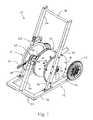
- FIG. 1is a perspective view of the exercise machine system of the present invention.
- FIG. 2is a side elevational view of the exercise machine system of the present invention as it might be positioned on a flat indoor floor surface or an outdoor ground surface.
- FIG. 3is a top plan view of the exercise machine system of the present invention.
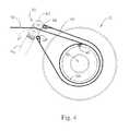
- FIG. 4is a detailed side view of the spool assembly and the guide roller assembly of the exercise machine system of the present invention showing the placement and routing of the straps.
- FIG. 5is a detailed perspective view of the brake assembly (resistance adjustment assembly) of the exercise machine system of the present invention.
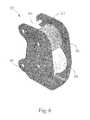
- FIG. 6is a detailed perspective view of the lead guide rollers assembly of the exercise machine system of the present invention.
- the exercise machine system of the present inventionis intended to provide a means for exercising by subjecting oneself to a resistive force while stepping, walking, or running away from a fixed point.
- Exercise machine 10 of the present inventionis comprised of a number of individual assemblies. Exercise machine 10 may be seen to comprise frame assembly 12 which incorporates and supports fly wheel assembly 14 , spool assembly 16 , and spring assembly 18 . The manner in which these assemblies interact is described in more detail below.
- a number of additional smaller assembliesare also included in the overall exercise machine system 10 of the present invention. These smaller assemblies, which are mounted at various places on frame assembly 12 , include lead guide rollers assembly 20 and resistance adjustment assembly (brake assembly) 22 . The structures of these two attachment assemblies are also described in more detail below.
- transport wheels 24are also positioned on frame assembly 12 .
- Transport wheel brackets 26are welded or bolted to frame base 28 of frame assembly 12 .
- base gripper pads 30Positioned on an underside of frame base 28 are base gripper pads 30 .
- Extending up from frame base 28are left frame arm 32 and right frame arm 34 . These two frame arms 32 and 34 extend upward (to support the rotating assemblies described in more detail below) into upper frame 36 which terminates in transport handle 38 .
- weight horn assembly 40Positioned on a rear facing side of frame base 28 of frame assembly 12 is weight horn assembly 40 which, in the preferred embodiment, is sized and structured to receive additional weights to provide further resistance to the unintended lateral movement of exercise machine 10 .
- Linear run-out strap 42is the component that is attached to the individual (by means of a harness and clip) at one end (a first loose end) and that is wound on spool assembly 16 at the opposite end.
- Linear run-out strap 42is unwound as the user moves outward from the front of exercise machine 10 .
- a second guide strap 44is positioned in a short loop around the spool assembly, covering and partially enclosing the linear run-out strap 42 . The manner in which guide strap 44 helps retain linear run-out strap 42 in a correct position and orientation on spool assembly 16 is described in more detail below.
- Lead guide rollers assembly 20is supported in an appropriate position adjacent spool assembly 16 by way of guide roller support arm 46 which is mounted on frame base 28 of frame assembly 12 .
- exercise machine system 10 of the present inventionis capable of functioning to provide a variable resistance backward force that the user runs against or otherwise moves against in the process of exercising.
- Exercise machine system 10may be moved to an appropriate position, either indoors or outdoors, with the overall weight of the device typically providing sufficient frictional force with the floor or ground surface to prevent its lateral motion during use. Additional weight may be added to exercise machine system 10 by the placement of typical disc weights (such as may be utilized on a barbell) onto weight horn assembly 40 .
- This assembly(shown in clearer detail in FIG. 2 ) is sized to receive the standard Olympic sized weight discs and to be retained thereon utilizing standard Olympic bar spring clips. The type of surface the device will be used on will typically determine whether addition weight will be required to hold it in place.
- the exercise machine system 10 of the present inventionmay be moved to the appropriate placement position by grasping transport handle 38 and tilting the entire machine backwards onto transport wheels 24 .
- Transport wheels 24are positioned such that when the machine is tilted back the wheels come into contact with the floor or ground and allow for the easy transport of the device.
- the deviceis then tilted forward such that transport wheels 24 no longer make contact with the floor or ground surface.
- the userretrieves the end of linear run-out strap 42 and clips this end onto a harness generally worn about the shoulders and chest.
- This harnessis preferably reversible and may be typically connected such that the clip-in point is on the back of the user, which allows the user to run forward away from the front of the exercise machine.
- the usermay choose to clip into linear run-out strap 42 on the front of the harness such that the user would move backwards from the machine to exercise different sets of muscles.
- Resistance adjustment assembly 22is fixed to the interior side of upper frame 36 in a position that allows it to come into spring loaded contact with flywheel assembly 14 .
- a knob adjustmentincreases or decreases the force exerted by resistance adjustment assembly 22 onto the peripheral surface of flywheel assembly 14 .
- a digital readoutprovides an indication of the force that has been dialed in by a particular user. The details of the structure of this alternate embodiment are shown below with respect to FIG. 5 .
- linear run-out strap 42Once clipped in to linear run-out strap 42 the user may then run or walk either forward or backward away from the front of exercise machine system 10 in a manner that allows the user to benefit from the retractive force generated by the exercise machine.
- This retractive forceis a combination of the inertia provided initially by flywheel assembly 14 which generally resists the rotational motion of the assembly and thereby initially resists the unwinding of the linear run-out strap 42 from spool assembly 16 .
- spring assembly 18comes into play the further the user is removed from the exercise machine 10 . As the user extracts the linear run-out strap 42 , spring assembly 18 begins providing greater resistance to this unwinding effort.
- Spring assembly 18includes a coil spring that, as the spinning assemblies of the exercise machine rotate in a manner directed by the movement of the user away from the machine, is coiled tighter within a fixed housing.
- the flywheel componentwhich initially provides an inertial resistance to rotational motion, begins to provide assistance to such rotational motion once it is rotating with some velocity.
- spring assembly 18provides generally little resistance initially, but as the spring within spring assembly 18 is wound tighter, the resistance force increases.
- flywheel assembly 14actually assists in the rotational movement and the motion outward by the user. As the spring in spring assembly 18 is wound tighter, it correspondingly provides a greater resistive force.
- linear run-out strap 42typically 40 yards in the preferred embodiment of the present invention
- the process of returning to the machinedirects a re-coiling or rewinding of linear run-out strap 42 as a result of the counter-rotation directed by the now tightly wound spring within spring assembly 18 .
- the return winding of the strapis likewise regulated in its speed by way of the interactive effects between flywheel assembly 14 and spring assembly 18 .
- flywheel assembly 14provides an inertial force counter to the tendency of spring assembly 18 to rotate and re-wind linear run-out strap 42 , the process of rewinding is carried out at a moderate rate rather than with any sudden jerking motions or with any great force.
- the combination of the rotating assembliestherefore acts as a governor to the speed with which the rotating assemblies turn all the while providing a relatively constant resistive force to the user during run-out and a constant retraction force during the rewinding return.
- FIG. 2is a side elevational view of the components situated on the left hand side of the device (as viewed from behind the device, such as when holding onto the transport handle). From this side view, spring assembly 18 can be seen in profile and the manner in which it is attached to upper frame 36 at left frame arm 32 is also disclosed. Spring assembly 18 is attached to left frame arm 32 at two spring assembly brackets 52 . Brackets 52 receive bolts extending from spring assembly enclosure 54 . Spin axle 48 is seen on end extending out of the center of spring assembly 18 . Spin axle 48 is retained within axle bearing 50 which is bolted to left frame arm 32 as shown. A similar bearing structure is provided on the opposite side of the frame.
- guide roller support arm 46which elevates and supports lead guide rollers assembly 20 .
- Linear run-out strap 42 and guide strap 44are omitted in FIG. 2 for clarity.
- transport wheel brackets 26are also positioned on frame assembly 12 extending above frame base 28 which each support a transport wheel 24 .
- weight horn assembly 40Seen between transport wheels 24 is weight horn assembly 40 .
- resistance adjustment assembly 22with a brake pad shown in contact with flywheel assembly 14 (not seen in the view from this side of the device).
- FIG. 3provides a top plan view of the exercise machine system of the present invention showing in greater detail the three spinning assemblies that make up the primary functional components of the system.
- frame assembly 12is seen to include frame base 28 as well as left frame arm 32 and right frame arm 34 which extend up to position and retain transport handle 32 .
- Weight horn assembly 40is seen positioned on the rear side of frame assembly 12 .
- Transport wheel brackets 26are positioned on each side of frame assembly 12 and support each of the two transport wheels 24 .
- Spin axle 48is shown to extend across frame assembly 12 and thereby positions and supports each of the three spinning assemblies including flywheel assembly 14 , spool assembly 16 , and spring assembly 18 .
- Lead guide rollers assembly 20is shown positioned at the end of guide roller support arm 46 which extends up from frame base 28 .
- linear run-out strap 42 and guide strap 44are omitted for clarity.
- the internal structure of spool assembly 16can better be seen in this view of FIG. 3 .
- FIG. 4is a detailed view of spool assembly 16 and lead guide rollers assembly 20 .
- Spool assembly 16is comprised of two parallel discs separated by a center drum 56 .
- the assemblyis positioned on spin axle 48 (not shown) by way of keyed center aperture 58 .
- a slot 60suitable for insertion of a fixed end of linear run-out strap 42 which retains a looped end section that may be retained by a pin positioned through the spool assembly.
- a fixed end of linear run-out strap 42is retained on drum 56 and may thereafter be wound by way of the rotation of spool assembly 16 .
- the opposite end of linear run-out strap 42extends from the surface of the drum (that is, from the surface of the extent to which the strap is wound about the drum 56 ) and between the rollers positioned within lead guide rollers assembly 20 .
- Top roller 62is approximately as wide as linear run-out strap 42 while bottom roller 64 contains a peripheral channel within which linear run-out strap 42 is held.
- top roller 62 and bottom roller 64serve to move linear run-out strap 42 in and out of spool assembly 16 in a flat orientation suitable for winding about spool assembly 16 . Therefore whether the linear run-out strap 42 is being drawn back into the system or is being pulled out from the system, the roller assembly serves to straighten the strap into a preferable orientation.
- Guide strap 44is a short section of strap similar in width dimension to linear run-out strap 42 .
- the purpose of guide strap 44is to facilitate the organized rewinding of linear run-out strap 42 onto spool assembly 16 .
- guide strap 44serves to prevent the bunching or entanglement of linear run-out strap 42 , primarily as it is returned into spool assembly 16 during the process of rewinding.
- Linear run-out strap 42could have a tendency to extend outside of the parallel discs that make up spool assembly 16 if it were not for the closure of the same by guide strap 44 .
- Resistance adjustment assembly 22comprising a resistance braking mechanism for adjusting the resistive force exerted by the system of the present invention.
- Resistance adjustment assembly 22comprises a housing 70 enclosing a pivoting brake arm 76 that pivotally retains brake pad 74 .
- Brake pad 74is curved on an underside surface so as to follow the contours of the perimeter surface of flywheel assembly 14 .
- Housing 70is rigidly mounted to the upper frame 36 , and more specifically to right frame arm 34 as shown in FIG. 1 .
- Bolt 78holds housing 70 to the frame of the machine, while also providing a pivot axle for brake lever arm 76 . In this manner, brake pad 74 , which in turn pivots on pin 80 extending through brake lever arm 76 , may ride on the peripheral surface of flywheel assembly 14 .
- Adjustments to the pressure with which the brake pad 74 is forced against flywheel assembly 14are made with adjustment knob 72 which extends through housing 70 with a threaded aperture and threaded end section 82 .
- This threaded adjustment mechanismallows the user to turn knob 72 and direct pressure against the brake spacing components situated on top of brake lever arm 76 .
- brake component retention pads 76Included among the spacing components compressed between brake lever arm 76 and adjustment knob 72 are brake component retention pads 76 which, in a first embodiment may simply fill the space between brake lever arm 76 and adjustment knob shaft 72 .
- load cell 84may be positioned between brake spacer components 86 and adjustable knob 72 so as to measure the force exerted between the movable brake lever arm 76 and the fixed housing 70 .
- digital display 88may be positioned on a handle portion on the upper frame 36 of exercise machine 10 in order to provide the user with a digital readout of the force that has been set as a resistance force against the flywheel.
- Lead guide rollers assembly 20is constructed of a U-shaped plate frame that is attached to guide roller support arm 46 as shown in FIG. 1 . Between the parallel faces of frame 90 are positioned top roller 62 and bottom roller 64 . As described above, top roller 62 is approximately the width of the linear run-out strap while bottom roller 64 comprises a recessed channel that is also approximately the width of the linear run-out strap.
- linear run-out strapis held between the rim edges of bottom roller 64 and is pressed into the recessed channel therein by top roller 62 .
- Linear run-out strap 42may then simply fed in either direction between the two rollers.
- Top roller 62is held within the frame 90 by way of axle pins 94 while bottom roller 64 is held within frame 90 by way of axle pin 92 .
- frame 90retains two further retention pins designed to hold the looped ends of guide strap 44 .
- Retention pin 66holds a first end of guide strap 44 that extends over the top of spool assembly 16 (not shown).
- Retention pin 68holds the opposite looped end of guide strap 44 after it passes behind and below spool assembly 16 , again as shown in FIG. 1 .
- guide strap 44presents a nearly closed loop around spool assembly 16 with the only point of exit being between rollers 62 and 64 for linear run-out strap 42 .
- guide rollers assembly 20helps to accurately and cleanly feed and retract the linear run-out strap of the exercise device of the present invention.
Landscapes
- Health & Medical Sciences (AREA)
- Orthopedic Medicine & Surgery (AREA)
- General Health & Medical Sciences (AREA)
- Physical Education & Sports Medicine (AREA)
- Life Sciences & Earth Sciences (AREA)
- Biophysics (AREA)
- Rehabilitation Therapy (AREA)
- Pulmonology (AREA)
- Rehabilitation Tools (AREA)
Abstract
Description
Claims (12)
Priority Applications (2)
| Application Number | Priority Date | Filing Date | Title |
|---|---|---|---|
| US12/764,074US8845497B2 (en) | 2009-04-20 | 2010-04-20 | Exercise machine for providing resistance to ambulatory motion of the user |
| US14/494,366US10065067B2 (en) | 2009-04-20 | 2014-09-23 | Exercise machine for providing resistance to ambulatory motion of the user |
Applications Claiming Priority (2)
| Application Number | Priority Date | Filing Date | Title |
|---|---|---|---|
| US21407809P | 2009-04-20 | 2009-04-20 | |
| US12/764,074US8845497B2 (en) | 2009-04-20 | 2010-04-20 | Exercise machine for providing resistance to ambulatory motion of the user |
Related Child Applications (1)
| Application Number | Title | Priority Date | Filing Date |
|---|---|---|---|
| US14/494,366Continuation-In-PartUS10065067B2 (en) | 2009-04-20 | 2014-09-23 | Exercise machine for providing resistance to ambulatory motion of the user |
Publications (2)
| Publication Number | Publication Date |
|---|---|
| US20100298104A1 US20100298104A1 (en) | 2010-11-25 |
| US8845497B2true US8845497B2 (en) | 2014-09-30 |
Family
ID=43011727
Family Applications (1)
| Application Number | Title | Priority Date | Filing Date |
|---|---|---|---|
| US12/764,074Active - Reinstated2032-06-15US8845497B2 (en) | 2009-04-20 | 2010-04-20 | Exercise machine for providing resistance to ambulatory motion of the user |
Country Status (2)
| Country | Link |
|---|---|
| US (1) | US8845497B2 (en) |
| WO (1) | WO2010123948A2 (en) |
Cited By (22)
| Publication number | Priority date | Publication date | Assignee | Title |
|---|---|---|---|---|
| US9643040B1 (en)* | 2015-07-29 | 2017-05-09 | Juan David Guerrero Diaz | Modular endurance conditioning tank system and method |
| US20170197104A1 (en)* | 2009-04-20 | 2017-07-13 | Joseph Turner | Exercise Machine for Providing Resistance to Ambulatory Motion of the User |
| US9776038B1 (en)* | 2016-03-18 | 2017-10-03 | High Spot Health Technology Co., Ltd. | Rowing simulation trainer |
| US10188890B2 (en) | 2013-12-26 | 2019-01-29 | Icon Health & Fitness, Inc. | Magnetic resistance mechanism in a cable machine |
| US10220259B2 (en) | 2012-01-05 | 2019-03-05 | Icon Health & Fitness, Inc. | System and method for controlling an exercise device |
| US10226396B2 (en) | 2014-06-20 | 2019-03-12 | Icon Health & Fitness, Inc. | Post workout massage device |
| US10252109B2 (en) | 2016-05-13 | 2019-04-09 | Icon Health & Fitness, Inc. | Weight platform treadmill |
| US10272317B2 (en) | 2016-03-18 | 2019-04-30 | Icon Health & Fitness, Inc. | Lighted pace feature in a treadmill |
| US10279212B2 (en) | 2013-03-14 | 2019-05-07 | Icon Health & Fitness, Inc. | Strength training apparatus with flywheel and related methods |
| US10293211B2 (en) | 2016-03-18 | 2019-05-21 | Icon Health & Fitness, Inc. | Coordinated weight selection |
| US10391361B2 (en) | 2015-02-27 | 2019-08-27 | Icon Health & Fitness, Inc. | Simulating real-world terrain on an exercise device |
| US10426989B2 (en) | 2014-06-09 | 2019-10-01 | Icon Health & Fitness, Inc. | Cable system incorporated into a treadmill |
| US10433612B2 (en) | 2014-03-10 | 2019-10-08 | Icon Health & Fitness, Inc. | Pressure sensor to quantify work |
| US10441840B2 (en) | 2016-03-18 | 2019-10-15 | Icon Health & Fitness, Inc. | Collapsible strength exercise machine |
| US10449416B2 (en) | 2015-08-26 | 2019-10-22 | Icon Health & Fitness, Inc. | Strength exercise mechanisms |
| US10493349B2 (en) | 2016-03-18 | 2019-12-03 | Icon Health & Fitness, Inc. | Display on exercise device |
| US10625137B2 (en) | 2016-03-18 | 2020-04-21 | Icon Health & Fitness, Inc. | Coordinated displays in an exercise device |
| US10661114B2 (en) | 2016-11-01 | 2020-05-26 | Icon Health & Fitness, Inc. | Body weight lift mechanism on treadmill |
| US10671705B2 (en) | 2016-09-28 | 2020-06-02 | Icon Health & Fitness, Inc. | Customizing recipe recommendations |
| US10940360B2 (en) | 2015-08-26 | 2021-03-09 | Icon Health & Fitness, Inc. | Strength exercise mechanisms |
| US20220203152A1 (en)* | 2020-12-31 | 2022-06-30 | Joong Chenn Industry Co., Ltd. | Towing equipment for sports |
| IT202200007718A1 (en)* | 2022-04-19 | 2023-10-19 | Desmotec S R L | SPORTS EQUIPMENT FOR PERFORMING REHABILITATION EXERCISES AND SPORTS TRAINING OR WARM-UP |
Families Citing this family (15)
| Publication number | Priority date | Publication date | Assignee | Title |
|---|---|---|---|---|
| GB201108398D0 (en)* | 2011-05-19 | 2011-07-06 | Loach Andrew | Hand-held exercise apparatus and resistance mechanism for exercise apparatus |
| DE102012110051A1 (en) | 2011-12-22 | 2013-06-27 | Harald Scheffer | Restraint device, in particular for training purposes |
| US9421413B2 (en)* | 2012-05-01 | 2016-08-23 | Rogers Athletic Company | Resistive pull exercise device |
| US9238159B2 (en)* | 2012-12-06 | 2016-01-19 | Auburn University | Log roll |
| US9802074B2 (en)* | 2014-07-18 | 2017-10-31 | Landscape Structures Inc. | Outdoor fitness resistance mechanism and housing |
| EP3294426A4 (en) | 2015-05-08 | 2018-12-19 | Vertimax, LLC | Systems and methods for over speed to resistive training |
| DE102015014536B4 (en)* | 2015-11-11 | 2019-01-03 | Milon Industries Gmbh | Cable outlet guide and cable training device |
| BR102016014608B1 (en)* | 2016-06-21 | 2020-01-21 | Carlos Alberto Leopoldo Da Camara Filho | exercise device system |
| CN106474674B (en)* | 2016-11-01 | 2019-04-23 | 国家体育总局体育科学研究所 | It is a kind of can measuring acceleration and thrust upper limb arm strength amount specialized training instrument |
| US10603535B2 (en) | 2017-12-01 | 2020-03-31 | Arx Fit, Inc. | Exercise machine with a force transducer |
| US12263368B2 (en) | 2018-08-03 | 2025-04-01 | Peloton Interactive, Inc. | Braking systems and methods for exercise equipment |
| CA3108622A1 (en) | 2018-08-03 | 2020-02-06 | Peloton Interactive, Inc. | Braking systems and methods for exercise equipment |
| US10874897B1 (en)* | 2020-07-02 | 2020-12-29 | David George Eastham, Jr. | Adjustable resistance weight sled with bias correction and wheel skid control |
| CN116573502B (en)* | 2023-04-28 | 2025-08-05 | 上海寅生科技有限公司 | Hub and fitness device |
| DE102023119024B3 (en) | 2023-07-19 | 2024-10-31 | Aerobis Fitness Gmbh | weight sled for fitness and strength training |
Citations (43)
| Publication number | Priority date | Publication date | Assignee | Title |
|---|---|---|---|---|
| US629655A (en) | 1898-01-21 | 1899-07-25 | William J Bryon Jr | Exercising apparatus. |
| US3519269A (en) | 1968-02-19 | 1970-07-07 | Joe R Howlett | Pulling friction type exercising device |
| US3972238A (en) | 1975-07-10 | 1976-08-03 | Richard Eugene Thatcher | Physical contact training apparatus |
| US4077626A (en)* | 1974-11-13 | 1978-03-07 | Joe Westley Newman | Exercising machine |
| US4135714A (en)* | 1976-02-03 | 1979-01-23 | Hughes Ralph L | Golf swing muscle developer |
| US4468026A (en) | 1982-04-29 | 1984-08-28 | Roark Carl D | Leg exercise apparatus with elevated stand and lower line grinding member |
| US4625962A (en)* | 1984-10-22 | 1986-12-02 | The Cleveland Clinic Foundation | Upper body exercise apparatus |
| US4822032A (en) | 1987-04-23 | 1989-04-18 | Whitmore Henry B | Exercise machine |
| US4830365A (en) | 1987-08-12 | 1989-05-16 | March Craig J | Home fitness gym |
| US4984986A (en) | 1989-11-07 | 1991-01-15 | Vohnout Vincent J | Apparatus and method for training oarsmen |
| US5242351A (en) | 1989-03-16 | 1993-09-07 | Berg Ernst H E | Flywheel inertial exercise device |
| US5466203A (en) | 1994-03-30 | 1995-11-14 | Chen; George | Magnetically controlled load adjusting structure of gymnastic apparatus |
| US5569138A (en) | 1995-06-05 | 1996-10-29 | Greenmaster Industrial Corp. | Multi-purpose exercising apparatus |
| US5586624A (en) | 1995-09-01 | 1996-12-24 | Ko; Wen-Chung | Fly wheel brake device for an exercise bicycle |
| US5613926A (en) | 1994-12-15 | 1997-03-25 | Michaelson; Kyron C. W. | Resistance and assistance physical training device |
| US6027429A (en) | 1993-11-03 | 2000-02-22 | Nordictrack, Inc. | Variable resistance exercise device |
| US6071215A (en) | 1997-04-26 | 2000-06-06 | Raffo; David M. | Multi-mode exercise machine |
| US6302829B1 (en)* | 1996-05-31 | 2001-10-16 | David H. Schmidt | Speed-control exercise method and apparatus |
| US20020025891A1 (en) | 2000-08-17 | 2002-02-28 | Colosky Paul E. | Gravity-independent constant force resistive exercise unit |
| US6413196B1 (en)* | 1999-04-29 | 2002-07-02 | Joel L. Crowson | Exercising device |
| US6599223B2 (en) | 2001-08-13 | 2003-07-29 | Leao Wang | Magnetic control multifunctional exercise apparatus |
| US6631866B1 (en)* | 1996-09-13 | 2003-10-14 | Oebrink Olov H. | Device for fly-fishing |
| US6634998B2 (en)* | 1999-08-24 | 2003-10-21 | Matt Siaperas | Multipurpose exercise apparatus |
| US6811520B2 (en) | 2001-08-13 | 2004-11-02 | Peter Wu | Magnetic control multifunctional exercise apparatus with double cable sheave |
| US6857993B2 (en) | 2003-07-11 | 2005-02-22 | Yong-Song Yeh | Magnetic tension control weight training machine |
| US6929587B2 (en)* | 1997-07-24 | 2005-08-16 | Richard D. Charnitski | Inertial resistance exercise apparatus and method |
| US7048638B2 (en)* | 2001-12-07 | 2006-05-23 | Novotny Milo R | Constant force golf swing training device, method of swing plane training and internet operation thereof |
| US7052440B2 (en) | 2002-05-29 | 2006-05-30 | Johnson Health Tech Co., Ltd. | Dual-function treading exerciser |
| US7169093B2 (en) | 1999-09-14 | 2007-01-30 | Free Motion Fitness, Inc. | Cable crossover exercise apparatus |
| US7192390B2 (en)* | 2003-10-21 | 2007-03-20 | Rene Ernest Berard | Expander type exercise device |
| USD552193S1 (en) | 2005-12-20 | 2007-10-02 | Husted Royce H | Exercise device |
| US7282016B2 (en) | 1999-09-14 | 2007-10-16 | Icon Ip, Inc. | Cable crossover exercise apparatus |
| US20070243979A1 (en) | 2006-04-14 | 2007-10-18 | Hand Richard A | Foot and leg exercising device providing passive motion benefits |
| US20070287601A1 (en) | 2006-06-12 | 2007-12-13 | Johnson Health Tech Co., Ltd | Exercise machine with semi-dependent retraction system |
| US7322905B2 (en)* | 2000-05-10 | 2008-01-29 | Morris Phillip E | Exercise machine with variable resistance unit and braking unit |
| US7462141B1 (en) | 2005-01-06 | 2008-12-09 | The United States Of America As Represented By The Administrator Of The National Aeronautics And Space Administration | Advanced resistive exercise device |
| US7637853B2 (en)* | 2004-08-16 | 2009-12-29 | Titan Athletic Group, Corp. | Conditioning and exercising device |
| US7641597B2 (en)* | 1996-05-31 | 2010-01-05 | David Schmidt | Dynamic isokinetic exercise apparatus |
| US7699724B1 (en)* | 2006-12-22 | 2010-04-20 | Roudy Derisse | Ball throwing muscle training apparatus |
| US7871359B2 (en)* | 2008-03-06 | 2011-01-18 | Product Labs Inc. | Resistance apparatus for exercise devices |
| US7878955B1 (en)* | 2008-12-04 | 2011-02-01 | Ehrlich Michael J | Integrated resistance spring force machine |
| US7922635B2 (en)* | 2000-03-10 | 2011-04-12 | Nautilus, Inc. | Adjustable-load unitary multi-position bench exercise unit |
| US8002677B2 (en)* | 2004-10-12 | 2011-08-23 | Nautilus, Inc. | Exercise device |
- 2010
- 2010-04-20WOPCT/US2010/031820patent/WO2010123948A2/enactiveApplication Filing
- 2010-04-20USUS12/764,074patent/US8845497B2/enactiveActive - Reinstated
Patent Citations (46)
| Publication number | Priority date | Publication date | Assignee | Title |
|---|---|---|---|---|
| US629655A (en) | 1898-01-21 | 1899-07-25 | William J Bryon Jr | Exercising apparatus. |
| US3519269A (en) | 1968-02-19 | 1970-07-07 | Joe R Howlett | Pulling friction type exercising device |
| US4077626A (en)* | 1974-11-13 | 1978-03-07 | Joe Westley Newman | Exercising machine |
| US3972238A (en) | 1975-07-10 | 1976-08-03 | Richard Eugene Thatcher | Physical contact training apparatus |
| US4135714A (en)* | 1976-02-03 | 1979-01-23 | Hughes Ralph L | Golf swing muscle developer |
| US4468026A (en) | 1982-04-29 | 1984-08-28 | Roark Carl D | Leg exercise apparatus with elevated stand and lower line grinding member |
| US4625962A (en)* | 1984-10-22 | 1986-12-02 | The Cleveland Clinic Foundation | Upper body exercise apparatus |
| US4822032A (en) | 1987-04-23 | 1989-04-18 | Whitmore Henry B | Exercise machine |
| US4830365A (en) | 1987-08-12 | 1989-05-16 | March Craig J | Home fitness gym |
| US5242351A (en) | 1989-03-16 | 1993-09-07 | Berg Ernst H E | Flywheel inertial exercise device |
| US4984986A (en) | 1989-11-07 | 1991-01-15 | Vohnout Vincent J | Apparatus and method for training oarsmen |
| US6027429A (en) | 1993-11-03 | 2000-02-22 | Nordictrack, Inc. | Variable resistance exercise device |
| US5466203A (en) | 1994-03-30 | 1995-11-14 | Chen; George | Magnetically controlled load adjusting structure of gymnastic apparatus |
| US5613926A (en) | 1994-12-15 | 1997-03-25 | Michaelson; Kyron C. W. | Resistance and assistance physical training device |
| US5569138A (en) | 1995-06-05 | 1996-10-29 | Greenmaster Industrial Corp. | Multi-purpose exercising apparatus |
| US5586624A (en) | 1995-09-01 | 1996-12-24 | Ko; Wen-Chung | Fly wheel brake device for an exercise bicycle |
| US6835167B2 (en)* | 1996-05-31 | 2004-12-28 | David H. Schmidt | Speed-controlled exercise method and apparatus |
| US6302829B1 (en)* | 1996-05-31 | 2001-10-16 | David H. Schmidt | Speed-control exercise method and apparatus |
| US7641597B2 (en)* | 1996-05-31 | 2010-01-05 | David Schmidt | Dynamic isokinetic exercise apparatus |
| US6631866B1 (en)* | 1996-09-13 | 2003-10-14 | Oebrink Olov H. | Device for fly-fishing |
| US6071215A (en) | 1997-04-26 | 2000-06-06 | Raffo; David M. | Multi-mode exercise machine |
| US6929587B2 (en)* | 1997-07-24 | 2005-08-16 | Richard D. Charnitski | Inertial resistance exercise apparatus and method |
| US6413196B1 (en)* | 1999-04-29 | 2002-07-02 | Joel L. Crowson | Exercising device |
| US6634998B2 (en)* | 1999-08-24 | 2003-10-21 | Matt Siaperas | Multipurpose exercise apparatus |
| US7282016B2 (en) | 1999-09-14 | 2007-10-16 | Icon Ip, Inc. | Cable crossover exercise apparatus |
| US7169093B2 (en) | 1999-09-14 | 2007-01-30 | Free Motion Fitness, Inc. | Cable crossover exercise apparatus |
| US7922635B2 (en)* | 2000-03-10 | 2011-04-12 | Nautilus, Inc. | Adjustable-load unitary multi-position bench exercise unit |
| US7322905B2 (en)* | 2000-05-10 | 2008-01-29 | Morris Phillip E | Exercise machine with variable resistance unit and braking unit |
| US6685602B2 (en)* | 2000-08-17 | 2004-02-03 | Paul E. Colosky, Jr. | Gravity-independent constant force resistive exercise unit |
| US20020025891A1 (en) | 2000-08-17 | 2002-02-28 | Colosky Paul E. | Gravity-independent constant force resistive exercise unit |
| US6599223B2 (en) | 2001-08-13 | 2003-07-29 | Leao Wang | Magnetic control multifunctional exercise apparatus |
| US6811520B2 (en) | 2001-08-13 | 2004-11-02 | Peter Wu | Magnetic control multifunctional exercise apparatus with double cable sheave |
| US7048638B2 (en)* | 2001-12-07 | 2006-05-23 | Novotny Milo R | Constant force golf swing training device, method of swing plane training and internet operation thereof |
| US7052440B2 (en) | 2002-05-29 | 2006-05-30 | Johnson Health Tech Co., Ltd. | Dual-function treading exerciser |
| US6857993B2 (en) | 2003-07-11 | 2005-02-22 | Yong-Song Yeh | Magnetic tension control weight training machine |
| US7192390B2 (en)* | 2003-10-21 | 2007-03-20 | Rene Ernest Berard | Expander type exercise device |
| US7637853B2 (en)* | 2004-08-16 | 2009-12-29 | Titan Athletic Group, Corp. | Conditioning and exercising device |
| US8002677B2 (en)* | 2004-10-12 | 2011-08-23 | Nautilus, Inc. | Exercise device |
| US7462141B1 (en) | 2005-01-06 | 2008-12-09 | The United States Of America As Represented By The Administrator Of The National Aeronautics And Space Administration | Advanced resistive exercise device |
| USD552193S1 (en) | 2005-12-20 | 2007-10-02 | Husted Royce H | Exercise device |
| US20070243979A1 (en) | 2006-04-14 | 2007-10-18 | Hand Richard A | Foot and leg exercising device providing passive motion benefits |
| US20070287601A1 (en) | 2006-06-12 | 2007-12-13 | Johnson Health Tech Co., Ltd | Exercise machine with semi-dependent retraction system |
| US7699724B1 (en)* | 2006-12-22 | 2010-04-20 | Roudy Derisse | Ball throwing muscle training apparatus |
| US7871359B2 (en)* | 2008-03-06 | 2011-01-18 | Product Labs Inc. | Resistance apparatus for exercise devices |
| US8328700B2 (en)* | 2008-03-06 | 2012-12-11 | Product Labs, Inc. | Resistance apparatus for exercise devices |
| US7878955B1 (en)* | 2008-12-04 | 2011-02-01 | Ehrlich Michael J | Integrated resistance spring force machine |
Cited By (24)
| Publication number | Priority date | Publication date | Assignee | Title |
|---|---|---|---|---|
| US20170197104A1 (en)* | 2009-04-20 | 2017-07-13 | Joseph Turner | Exercise Machine for Providing Resistance to Ambulatory Motion of the User |
| US10065067B2 (en)* | 2009-04-20 | 2018-09-04 | Joseph Turner | Exercise machine for providing resistance to ambulatory motion of the user |
| US10220259B2 (en) | 2012-01-05 | 2019-03-05 | Icon Health & Fitness, Inc. | System and method for controlling an exercise device |
| US10279212B2 (en) | 2013-03-14 | 2019-05-07 | Icon Health & Fitness, Inc. | Strength training apparatus with flywheel and related methods |
| US10188890B2 (en) | 2013-12-26 | 2019-01-29 | Icon Health & Fitness, Inc. | Magnetic resistance mechanism in a cable machine |
| US10433612B2 (en) | 2014-03-10 | 2019-10-08 | Icon Health & Fitness, Inc. | Pressure sensor to quantify work |
| US10426989B2 (en) | 2014-06-09 | 2019-10-01 | Icon Health & Fitness, Inc. | Cable system incorporated into a treadmill |
| US10226396B2 (en) | 2014-06-20 | 2019-03-12 | Icon Health & Fitness, Inc. | Post workout massage device |
| US10391361B2 (en) | 2015-02-27 | 2019-08-27 | Icon Health & Fitness, Inc. | Simulating real-world terrain on an exercise device |
| US9643040B1 (en)* | 2015-07-29 | 2017-05-09 | Juan David Guerrero Diaz | Modular endurance conditioning tank system and method |
| US10940360B2 (en) | 2015-08-26 | 2021-03-09 | Icon Health & Fitness, Inc. | Strength exercise mechanisms |
| US10449416B2 (en) | 2015-08-26 | 2019-10-22 | Icon Health & Fitness, Inc. | Strength exercise mechanisms |
| US10625137B2 (en) | 2016-03-18 | 2020-04-21 | Icon Health & Fitness, Inc. | Coordinated displays in an exercise device |
| US9776038B1 (en)* | 2016-03-18 | 2017-10-03 | High Spot Health Technology Co., Ltd. | Rowing simulation trainer |
| US10441840B2 (en) | 2016-03-18 | 2019-10-15 | Icon Health & Fitness, Inc. | Collapsible strength exercise machine |
| US10493349B2 (en) | 2016-03-18 | 2019-12-03 | Icon Health & Fitness, Inc. | Display on exercise device |
| US10293211B2 (en) | 2016-03-18 | 2019-05-21 | Icon Health & Fitness, Inc. | Coordinated weight selection |
| US10272317B2 (en) | 2016-03-18 | 2019-04-30 | Icon Health & Fitness, Inc. | Lighted pace feature in a treadmill |
| US10252109B2 (en) | 2016-05-13 | 2019-04-09 | Icon Health & Fitness, Inc. | Weight platform treadmill |
| US10671705B2 (en) | 2016-09-28 | 2020-06-02 | Icon Health & Fitness, Inc. | Customizing recipe recommendations |
| US10661114B2 (en) | 2016-11-01 | 2020-05-26 | Icon Health & Fitness, Inc. | Body weight lift mechanism on treadmill |
| US20220203152A1 (en)* | 2020-12-31 | 2022-06-30 | Joong Chenn Industry Co., Ltd. | Towing equipment for sports |
| US11679295B2 (en)* | 2020-12-31 | 2023-06-20 | Joong Chenn Industry Co., Ltd. | Towing equipment for sports |
| IT202200007718A1 (en)* | 2022-04-19 | 2023-10-19 | Desmotec S R L | SPORTS EQUIPMENT FOR PERFORMING REHABILITATION EXERCISES AND SPORTS TRAINING OR WARM-UP |
Also Published As
| Publication number | Publication date |
|---|---|
| WO2010123948A3 (en) | 2011-03-24 |
| WO2010123948A2 (en) | 2010-10-28 |
| US20100298104A1 (en) | 2010-11-25 |
Similar Documents
| Publication | Publication Date | Title |
|---|---|---|
| US8845497B2 (en) | Exercise machine for providing resistance to ambulatory motion of the user | |
| US10065067B2 (en) | Exercise machine for providing resistance to ambulatory motion of the user | |
| US5195937A (en) | Multi-exercise apparatus | |
| US5302161A (en) | Flexible line guidance and tension measuring device | |
| US4728102A (en) | Resistance indicator for frictionally resistant exercise device | |
| US9700753B1 (en) | Personal force resistance cable exercise device, force resistance assembly, and method of exercising | |
| US9731157B2 (en) | Hand-held exercise apparatus and resistance mechanism for exercise apparatus | |
| US6790163B1 (en) | Swim stroke exercise device | |
| US10426989B2 (en) | Cable system incorporated into a treadmill | |
| US10143880B1 (en) | Cable exercise device and method | |
| US10220235B2 (en) | Controlled motion exercise device | |
| US8025608B2 (en) | Continuous rope pulling exercise apparatus | |
| US5013033A (en) | Rowing apparatus | |
| US7087001B1 (en) | Portable handheld exercise apparatus which can be attached to a multiplicity of body parts | |
| US3885789A (en) | Exercising device | |
| US8608626B2 (en) | Rowing machine simulator | |
| US4346886A (en) | Variable resistance exercising device | |
| WO1994027679A1 (en) | Electromechanical resistance exercise apparatus | |
| US20220161088A1 (en) | Exercise device having a power rewind | |
| US11077334B2 (en) | Rower with articulating footpads | |
| US7112165B1 (en) | Exercise machine | |
| JP6491639B2 (en) | Exercise equipment | |
| TW202100206A (en) | Exercise methods and apparatus | |
| US8147382B2 (en) | Physical training system | |
| US20050062253A1 (en) | Occupant driven mobile device |
Legal Events
| Date | Code | Title | Description |
|---|---|---|---|
| FEPP | Fee payment procedure | Free format text:MAINTENANCE FEE REMINDER MAILED (ORIGINAL EVENT CODE: REM.) | |
| LAPS | Lapse for failure to pay maintenance fees | Free format text:PATENT EXPIRED FOR FAILURE TO PAY MAINTENANCE FEES (ORIGINAL EVENT CODE: EXP.); ENTITY STATUS OF PATENT OWNER: MICROENTITY | |
| PRDP | Patent reinstated due to the acceptance of a late maintenance fee | Effective date:20181128 | |
| FEPP | Fee payment procedure | Free format text:PETITION RELATED TO MAINTENANCE FEES GRANTED (ORIGINAL EVENT CODE: PMFG); ENTITY STATUS OF PATENT OWNER: MICROENTITY Free format text:PETITION RELATED TO MAINTENANCE FEES FILED (ORIGINAL EVENT CODE: PMFP); ENTITY STATUS OF PATENT OWNER: MICROENTITY Free format text:SURCHARGE, PETITION TO ACCEPT PYMT AFTER EXP, UNINTENTIONAL (ORIGINAL EVENT CODE: M3558); ENTITY STATUS OF PATENT OWNER: MICROENTITY Free format text:ENTITY STATUS SET TO MICRO (ORIGINAL EVENT CODE: MICR); ENTITY STATUS OF PATENT OWNER: MICROENTITY | |
| MAFP | Maintenance fee payment | Free format text:PAYMENT OF MAINTENANCE FEE, 4TH YEAR, MICRO ENTITY (ORIGINAL EVENT CODE: M3551); ENTITY STATUS OF PATENT OWNER: MICROENTITY Year of fee payment:4 | |
| STCF | Information on status: patent grant | Free format text:PATENTED CASE | |
| FEPP | Fee payment procedure | Free format text:MAINTENANCE FEE REMINDER MAILED (ORIGINAL EVENT CODE: REM.); ENTITY STATUS OF PATENT OWNER: MICROENTITY | |
| FEPP | Fee payment procedure | Free format text:SURCHARGE FOR LATE PAYMENT, MICRO ENTITY (ORIGINAL EVENT CODE: M3555); ENTITY STATUS OF PATENT OWNER: MICROENTITY | |
| MAFP | Maintenance fee payment | Free format text:PAYMENT OF MAINTENANCE FEE, 8TH YEAR, MICRO ENTITY (ORIGINAL EVENT CODE: M3552); ENTITY STATUS OF PATENT OWNER: MICROENTITY Year of fee payment:8 |