US8844942B1 - Quick-load connector for a surgical tool - Google Patents
Quick-load connector for a surgical toolDownload PDFInfo
- Publication number
- US8844942B1 US8844942B1US13/169,742US201113169742AUS8844942B1US 8844942 B1US8844942 B1US 8844942B1US 201113169742 AUS201113169742 AUS 201113169742AUS 8844942 B1US8844942 B1US 8844942B1
- Authority
- US
- United States
- Prior art keywords
- connector
- sleeve
- housing
- ball
- distal
- Prior art date
- Legal status (The legal status is an assumption and is not a legal conclusion. Google has not performed a legal analysis and makes no representation as to the accuracy of the status listed.)
- Active, expires
Links
Images


Classifications
- B—PERFORMING OPERATIONS; TRANSPORTING
- B23—MACHINE TOOLS; METAL-WORKING NOT OTHERWISE PROVIDED FOR
- B23B—TURNING; BORING
- B23B31/00—Chucks; Expansion mandrels; Adaptations thereof for remote control
- B23B31/02—Chucks
- B23B31/10—Chucks characterised by the retaining or gripping devices or their immediate operating means
- B23B31/107—Retention by laterally-acting detents, e.g. pins, screws, wedges; Retention by loose elements, e.g. balls
- B23B31/1071—Retention by balls
- A—HUMAN NECESSITIES
- A61—MEDICAL OR VETERINARY SCIENCE; HYGIENE
- A61B—DIAGNOSIS; SURGERY; IDENTIFICATION
- A61B17/00—Surgical instruments, devices or methods
- A61B17/16—Instruments for performing osteoclasis; Drills or chisels for bones; Trepans
- A61B17/1613—Component parts
- A61B17/162—Chucks or tool parts which are to be held in a chuck
- B—PERFORMING OPERATIONS; TRANSPORTING
- B25—HAND TOOLS; PORTABLE POWER-DRIVEN TOOLS; MANIPULATORS
- B25G—HANDLES FOR HAND IMPLEMENTS
- B25G3/00—Attaching handles to the implements
- B25G3/02—Socket, tang, or like fixings
- B25G3/12—Locking and securing devices
- Y—GENERAL TAGGING OF NEW TECHNOLOGICAL DEVELOPMENTS; GENERAL TAGGING OF CROSS-SECTIONAL TECHNOLOGIES SPANNING OVER SEVERAL SECTIONS OF THE IPC; TECHNICAL SUBJECTS COVERED BY FORMER USPC CROSS-REFERENCE ART COLLECTIONS [XRACs] AND DIGESTS
- Y10—TECHNICAL SUBJECTS COVERED BY FORMER USPC
- Y10T—TECHNICAL SUBJECTS COVERED BY FORMER US CLASSIFICATION
- Y10T279/00—Chucks or sockets
- Y10T279/17—Socket type
- Y10T279/17128—Self-grasping
- Y10T279/17136—Yielding grasping jaws
- Y10T279/17145—Ball or roller
- Y—GENERAL TAGGING OF NEW TECHNOLOGICAL DEVELOPMENTS; GENERAL TAGGING OF CROSS-SECTIONAL TECHNOLOGIES SPANNING OVER SEVERAL SECTIONS OF THE IPC; TECHNICAL SUBJECTS COVERED BY FORMER USPC CROSS-REFERENCE ART COLLECTIONS [XRACs] AND DIGESTS
- Y10—TECHNICAL SUBJECTS COVERED BY FORMER USPC
- Y10T—TECHNICAL SUBJECTS COVERED BY FORMER US CLASSIFICATION
- Y10T279/00—Chucks or sockets
- Y10T279/17—Socket type
- Y10T279/17128—Self-grasping
- Y10T279/17171—One-way-clutch type
- Y10T279/17188—Side detent
- Y10T279/17196—Ball or roller
- Y—GENERAL TAGGING OF NEW TECHNOLOGICAL DEVELOPMENTS; GENERAL TAGGING OF CROSS-SECTIONAL TECHNOLOGIES SPANNING OVER SEVERAL SECTIONS OF THE IPC; TECHNICAL SUBJECTS COVERED BY FORMER USPC CROSS-REFERENCE ART COLLECTIONS [XRACs] AND DIGESTS
- Y10—TECHNICAL SUBJECTS COVERED BY FORMER USPC
- Y10T—TECHNICAL SUBJECTS COVERED BY FORMER US CLASSIFICATION
- Y10T279/00—Chucks or sockets
- Y10T279/17—Socket type
- Y10T279/17666—Radially reciprocating jaws
- Y10T279/17692—Moving-cam actuator
- Y10T279/17743—Reciprocating cam sleeve
- Y10T279/17752—Ball or roller jaws
Definitions
- the present inventionrelates generally to surgical instruments for use in orthopedic tools.
- the present inventionrelates to a connector for securing an orthopedic tool to a drive device.
- Surgical tools for use in the cutting of bone and tissueare conventional in the art. Many of these tools are connected to a handle or motor, which is used to manipulate and drive the tool during a surgical procedure.
- these toolsare used to cut and shape bone as well as remove tissue in preparation for insertion of an orthopedic implant. As such, these procedures require that bone and/or tissue be precisely cut and/or removed to ensure proper positioning and fit of an orthopedic implant. Any unexpected movement of the surgical tool during use, such as handle slippage, unintentional rotation, or mechanical play, is not optimal as it could result in undesirable surgical outcomes.
- some prior connector devicesrequire that the locking mechanism be activated before insertion of the tool shaft. This limitation requires an additional step in connecting the tool to a handle during the surgical procedure. Activation of the locking mechanism may require assistance which may not be available when required. Furthermore, the orientation of such a connector activation mechanism may not be ideally positioned during the surgical procedure. For example, a button or lever mechanism may be oriented in a position that is difficult to reach or is not accessible. Unlike these prior art devices, a tool drive shaft is simply inserted and advanced into the connector of the present invention where it is locked into place. This locking feature of the connector of the present invention provides an efficient and secure means by which a tool is connected to a drive device, such as a handle or motor.
- a drive devicesuch as a handle or motor.
- a connector locking mechanismthat offers a more secure, robust, easy to use, efficient connection between an orthopedic tool and drive device is provided by the present invention.
- the connector of the present inventioncomprises a ball and a spring-loaded sleeve mechanism, which engages a groove that circumferentially extends around the drive shaft of a tool.
- the tool drive shaftis locked into place by a series of locking balls, which are forced into an annular groove of the drive shaft by the spring-loaded sleeve.
- the mechanism of the present inventionis designed such that when in the locked position, forward and rearward movement of the tool drive shaft is prevented by an interference relationship of the balls captured between the spring-loaded sleeve and the annular groove of the tool drive shaft.
- the connector mechanism of the present inventionaccommodates drive shafts of differing size diameters.
- the spring-loaded sleeve, located within the mechanism,enables the balls to lock with shafts of differing diameters, both large and small.
- the spring action of the sleeve mechanism of the present inventionallows for the locking balls to contact drive shafts of different diameters. This enables an operator to robustly secure tool drive shafts with diameter tolerance variations.
- the design of the present connector mechanismdoes not require special tool shaft designs. Existing tool drive shafts can easily be inserted and locked into the connector of the present invention.
- the features of the locking mechanism of the connector of the present inventionaddress the shortcomings of prior locking connectors.
- the present connectorprovides a more reliable and selectively releasable connection between the surgical tool and its handle or motor, thereby reducing undesired mechanical movement such as mechanical play, slippage and/or unintentional rotation between the tool drive shaft and the handle or motor.
- the present inventionprovides a mechanical connector by which a tool drive shaft is connected, or coupled, and releasibly secured to a drive device.
- the tool drive shaftmay comprise the shaft of an orthopedic tool such as a reamer, a bone cutter, a retractor, a saw, a drill, or the like.
- the drive devicemay comprise a handle, a motor or another drive shaft.
- the present connectorcomprises a locking mechanism sub-assembly positioned circumferentially around an elongated cylindrically shaped body.
- a connector housingencloses the locking mechanism therewithin. The distal and proximal ends of the cylinder extend through their respective ends of the connector housing.
- a through-boreextending along a central longitudinal axis of the body, is dimensioned to receive a drive shaft.
- the locking mechanism sub-assemblycomprises a spring-loaded sleeve and a series of locking balls. Each of the locking balls is individually received in respective slots that extend through a wall of the body.
- the spring-loaded sleeveis positioned circumferentially over the body such that the sleeve is in an axially manipulatable relationship along the longitudinal axis of the body.
- a springpositioned proximal of the sleeve, exerts a biasing force that is selectively manipulatable to retain the locking balls within their respective slot of the body. In the locked position, a portion of each ball protrudes through its slot into the through-bore opening of the body. It is this portion of the ball that interfaces with the annular groove of the tool drive shaft to thereby secure the tool within the connector.
- the “quick-load” aspect of the connector of the present inventionallows the tool drive shaft to be quickly inserted and secured to a handle drive device by simply advancing the drive shaft into the connector. Once secured in the connector, the tool drive shaft cannot be removed from the handle until the collar is pulled in a backwards or distal direction, away from the tool drive shaft located within the connector. Alternatively, the tool drive shaft could also be removed by advancing a distal end portion of the connector body in a proximal direction into the connector.
- the outer surface of the tool drive shaftforces the locking balls upwardly or laterally into the body slot and away from the drive shaft.
- the drive shaftis further advanced into the body of the connector until its annular groove is aligned with the cylinder slot. Once the drive shaft groove and cylinder slot are aligned, the ball residing within the slot is captured in the groove of the tool drive shaft by the spring-loaded sleeve, thereby locking the tool to the connector.
- the spring-loaded sleevelocated within the body of the present connector provides a sufficient amount of tension to the balls in the groove of the drive shaft, thereby locking the drive shaft within the connector.
- An angled interior wall of the cylinder slotprevents release movement of the tool drive shaft from the connector. That is because the locking balls are incapable of advancing past the interior cylinder wall. Likewise, rearward movement of the drive shaft is impeded by an interior wall surface of the housing.
- the drive shaftis released from the connector by pulling the collar housing in a proximal direction, away from the distal end of the tool drive shaft. This action causes a lip of the collar housing to contact the locking balls and move them in an upwardly or lateral direction out of the tool groove, thereby freeing the tool drive shaft from the interference fit with the locking balls.
- the tool drive shaftcan be removed by pushing the distal end portion of the connector body, either the nozzle portion or the cylinder portion, proximally into the connector. This alternate action causes an edge located at a proximal end of the nozzle or distal portion of the cylinder, to contact the locking balls and move them in an upwardly or lateral direction out of the tool groove. Once the balls have been removed from the annular groove of the tool drive shaft, the tool can be removed from the connector.
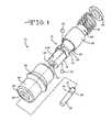
- FIG. 1is an exploded perspective view of the connector mechanism of the present invention.
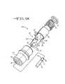
- FIG. 1Ais an exploded perspective view of an alternate embodiment of the present connector.
- FIG. 2is a cross-sectional view of the connector mechanism of the present invention during initial insertion of a tool drive shaft.
- FIG. 3is a cross-sectional view of the present connector during insertion of the tool drive shaft.
- FIG. 4is a cross-sectional view of the present connector locking mechanism illustrating further insertion of the tool drive shaft.
- FIG. 5is a cross-sectional view illustrating a locked tool drive shaft in the connector mechanism of the present invention.
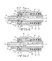
- FIG. 6is a cross-sectional view illustrating the tool drive shaft beginning to be released from the connector mechanism of the present invention.
- FIG. 7is a cross-sectional view illustrating the locking balls removed from the annular groove of the drive shaft.
- FIG. 8is a cross-sectional view illustrating an alternate embodiment of the locking balls being removed from the annular groove of the drive shaft.
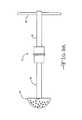
- FIG. 9Ais a side view illustrating the present connector connected to an orthopedic tool and a handle.
- FIG. 9Bis a side view illustrating the present connector connected to an orthopedic tool and a motor.
- FIGS. 1-9Billustrate embodiments of the connector mechanism 10 of the present invention.
- the connector 10comprises an elongated cylindrically shaped body 12 , a nozzle portion 14 of the body, a sleeve 16 positioned circumferentially around the body 12 , a spring 18 , a bushing 20 , and at least one locking ball 22 .
- a collar 24serves as a housing for the present connector 10 .
- the body 12comprises a proximal cylindrical portion and a distal cylindrical portion with a planar portion 26 A of a reduced outer diameter ( FIG. 1A ). More preferably, the body 12 comprises a distal cylindrically shaped nozzle 14 connected to a proximal main cylinder 26 of an increased diameter. The cylindrically shaped nozzle 14 also comprises a planar portion 14 A along its outer diameter ( FIG. 1 ).
- the main cylinder 26has a length extending between a cylinder distal end portion 28 , and a cylinder proximal end portion 30 .
- the main cylinder 26is constructed with a through-bore 32 that extends along a central longitudinal axis A-A thereof.
- a cylinder wall 34surrounds the through-bore 32 and extends along the longitudinal axis A-A.
- the cylinder through-bore 32 of the main cylinder 26is dimensioned to receive a tool drive shaft 36 , more preferably a distal end portion 38 of the tool drive shaft 36 .
- the main cylinder 26has a diameter from about 0.5 cm to about 5.0 cm, with the through-bore 32 preferably having a diameter from about 0.3 cm to about 3.0 cm.
- the housing 24is positioned over the connector 10 such that it encloses the connector 10 therewithin.
- the body 12comprises a distal cylindrically-shaped nozzle 14 connected to a proximal, main cylinder 26 of an increased outer diameter.
- the nozzle 14extends from a nozzle distal end portion 40 to a nozzle proximal end portion 42 and is fluidly connected to a distal end 28 of the main cylinder 26 .
- a distal end 46 of the nozzle 14protrudes through an opening 48 at the distal end 50 of the connector housing 24 .
- the nozzle 14is attached to the main cylinder 26 such that a nozzle through-bore 52 is coaxial with the longitudinal axis A-A of the main cylinder 26 .
- a slot 54is provided through a wall 56 of the nozzle 14 and delineates the proximal nozzle portion 42 from the main cylinder 26 .
- the connector 10 Acan be constructed without the nozzle 14 and the main cylinder 26 being separate parts.
- the cylinder 26is elongated such that its distal end 44 protrudes through the distal opening 48 of the connector housing 24 .
- the slot 54may reside where the cylindrical body portions 14 , 26 meet each other ( FIG. 1 ).
- the slot 54may be positioned through the wall 34 of the cylinder 26 ( FIG. 1A ) or through the wall 56 of the nozzle 14 . More preferably, the slot 54 , may be positioned within the distal end portion 28 of the cylinder 26 . Whether positioned through the nozzle 14 and/or cylinder 26 , it is preferred that at least two slots 54 extend through their respective wall thicknesses that comprise the body 12 of the present connector 10 , 10 A.
- An orthopedic tool 92including but not limited to a reamer, a bone cutter, a saw, a retractor, a drill, and the like, is releasibly connectable or couplable to the distal end portion 28 , 40 of the cylinder 26 or nozzle 14 comprising the connector 10 , 10 A.
- a handle 90 or a motor 94preferably connects to the proximal end portion 30 of the cylinder 26 .
- the tool 92 or the handle 90 or the motor 94could be attached to their respective opposite ends of the connector 10 , 10 A.
- FIGS. 9A and 9BNon-limiting examples of the connector 10 , 10 A of the present invention are illustrated in FIGS. 9A and 9B showing the connector 10 , 10 A connected to an orthopedic tool 92 and a handle 90 ( FIG. 9A ) as well as an orthopedic tool 92 and a motor 94 ( FIG. 9B ).
- the sleeve 16having a length extending from a sleeve distal end 58 to a sleeve proximal end 60 , is preferably positioned over the proximal end portion 30 of the main cylinder 26 .
- the sleeve 16has a sleeve through-bore 62 through which the cylinder 26 resides.
- the sleeve 16is preferably mounted in, an axially manipulatable relationship over the main cylinder 26 .
- the sleeve 16is positioned in an axial slidable relationship over an outer surface 64 of the main cylinder 26 in a co-axial relationship with the longitudinal axis A-A.
- the spring 18is positioned over the proximal end portion 30 of the main cylinder 26 .
- the spring 18is further positioned such that its proximal end contacts the proximal end 60 of the sleeve 16 .
- the bushing 20is positioned over the proximal end 30 of the cylinder 26 and contacts the other end of the spring 18 .
- the spring 18therefore, resides between the sleeve 16 and the bushing 20 .
- the bushing 20acts as a “back stop” preventing the spring 18 from moving in a distal direction along the main cylinder 26 .
- the proximal end of the spring 18contacts the stationary bushing 20 as its biasing force is changed by forward or distal and rearward or proximal movement of the sleeve 16 within the housing 24 .
- the spring 18provides tension that normally forces the sleeve 16 distally within the connector housing 24 .
- the locking ball 22is received within the slot 54 that extends through the wall of the body 12 where the distal cylindrical portion 28 meets the proximal nozzle portion 42 ( FIGS. 1 ). A portion of the ball 22 protrudes below an inner wall surface 66 of the body 12 .
- there are at least two balls 22 positioned opposite each other within the present connector 10as shown in FIGS. 2-8 . Although two balls 22 are preferred, it is contemplated that additional balls 22 could be positioned circumferentially around the cylinder 26 or nozzle 14 within the connector 10 , 10 A.
- the drive shaft 36forces the ball or balls 22 outwardly and latterly along the slot 54 .
- the ball 22retreats within the slot 54 , pushing against the distal end 58 of the sleeve 16 , thus forcing the sleeve 16 against the spring 18 .
- the distal end 58 of the sleeve 16is preferably designed with a cutout portion 68 .
- This cutout portion 68has a frusto-conical shape that extends outwardly and distally from an inner surface 76 of the sleeve 16 part-way through a thickness thereof at an angle of from about 35° to about 55° with respect to the longitudinal axis A-A, where it meets a cylindrical ledge 70 extending to the distal end 58 of the sleeve 16 .
- the cutout 68is designed to allow a portion of the ball 22 to reside therein.
- the ball 22rides along the outer surface 72 of the drive shaft 36 .
- the distal end portion 38 of the shaft 36is further advanced until its annular groove 74 is aligned with the slot opening 54 provided in the body 12 where the ball 22 resides.
- the ball 22within the slot 54 , falls into the annular groove 74 of the tool drive shaft 36 .
- the angled distal edge 76 of the sleeve 16 in combination with the spring 18imparts a downward force onto the ball 22 , locking the shaft 36 therewithin.
- about 10 percent to about 45 percent of the diameter of the ball 22resides within the annular groove 74 of the drive shaft 36 when in the locked position.
- the spring-loaded sleeve 16 and ball 22 feature of the present connector 10 , 10 Aprevent both forward and rearward (proximal and distal) movement of the tool drive shaft 36 .
- Forward or proximal movement of the tool 92is prohibited because such movement forces the ball 22 against an interior wall surface 78 A of the slot 54 .
- the interior wall surface 78 A of the slot 54is angled such that the ball 22 cannot move out of the groove 74 .
- the interior wall surface 78 A of each slot 54is at an angle ranging from about 35′ to about and more preferably at about 45° with respect to the longitudinal axis A-A.
- rearward or distal movement of the drive shaft 36is prohibited by an annular lip 80 of the housing 24 . As shown in FIGS. 2-5 , the lip 80 is oriented at a normal relationship with respect to the longitudinal axis A-A.
- a centerline BB of the ball 22is positioned below the outer surface 84 of the proximal cylindrical portion 28 , of the body 12 , thus preventing the ball 22 from becoming dislodged from its position within the annular groove 74 of the tool shaft 36 .
- the drive shaft 36is removed from the connector 10 , 10 A by applying a force the housing 24 in a proximal direction as indicated by arrow 86 towards the proximal end 30 of the cylinder 26 ( FIGS. 6 and 7 ).
- the interior wall surface 82 of the housing 24contacts the ball 22 and the distal edge 58 of the sleeve 16 as it moves in a proximal direction toward the proximal end 30 of the cylinder 26 .
- a ridge 88circumferentially surrounding the collar housing 24 provides a raised surface by which the user can manipulate the collar in both a forwardly or distal and a rearwardly or proximal direction.
- the annular lip 80 of the connector housing 24contacts the ball 22 .
- the lip 80continues in a proximal direction, the ball 22 is pushed up the angled interior surface 78 A of the slot 54 .
- the cutout portion 68 of the sleeve 16allows space for the ball 22 to roll therewithin.
- the interior surface 78 A of the slot 54acts as a ramp surface, which allows the ball 22 to roll out of the annular groove 74 of the tool shaft 36 .
- edge 85 of the interior surface 78 Aacts similarly to a scoop in that it works in concert with annular lip 80 to pick the ball 22 out of the groove 74 .
- the centerline B-B of the ball 22When in the locked position shown in FIG. 5 , the centerline B-B of the ball 22 is spaced at or above the cylindrical outer surface 14 A of the nozzle portion 14 or the distal cylindrical portion 26 A of the connector 10 A shown in FIG. 1A .
- This relative positioningenables the annular lip 80 of the housing 24 to contact the ball 22 to initiate movement of the ball 22 in an upwardly and lateral direction out of the annular groove 74 in the tool drive shaft 36 as shown in FIG. 6 .
- the applied forcecauses the housing 24 to contact the sleeve 16 to move the sleeve in a proximal direction, which compresses the spring 18 against the bushing 20 .
- an edge 83 of the lip 80is either aligned along the center line BB of the ball 22 or somewhat spaced toward the tool drive shaft with respect to the axis B-B. This relative positioning causes the edge 83 of the lip 80 to “pick” the ball 22 out of the annular groove 74 in the tool drive shaft 36 and push it out and up surface 78 A.
- edge 85 of surface 78 A together with edge 83impart a “scooping” action onto ball 22 that pushes up surface 78 A and out of groove 74 .
- edge 85 of the interior surface 78 A of slot 54resides below the centerline B-B of the ball 22 .
- the position of edge 85 of the angled interior surface 78 Aimparts a “scooping” action below the equator of the ball 22 which helps lift the ball out of the groove 74 .
- the connector 10 , 10 A of the present inventioncould be designed such that it is released through proximal movement of the distal end portion of the body 12 .
- the proximal portion 28 , 42 of the distal end portion of the connector 10 , 10 Ais slid between lip 80 and surface 72 of the drive shaft 36 while the housing 24 is in a stationary position.
- surface 78 Bis a mirror image of surface 78 A.
- Surface 78 Blike surface 78 A, is angled from about 35° to about 55° degrees with respect to longitudinal axis A-A.
- surface 78 Bacts as a ramp surface that “picks” ball 22 out of groove 74 of the tool drive shaft.
- surface 78 Bmoves in a proximal direction it preferably contacts the ball 22 below centerline B-B, pushing it out of the groove, onto surface 78 A and out of groove 74 . This action further compresses spring 18 as the ball 22 contacts surface 76 of sleeve 16 within the housing 24 .
- surface 78 Bis non-limiting and could comprise the proximal end of the nozzle 14 or a distal portion 28 of the cylinder 26 . Furthermore, it is contemplated that surface 78 B could comprise the proximal end of a sleeve or tube that is positioned over the distal end portion of the body 12 .
Landscapes
- Health & Medical Sciences (AREA)
- Engineering & Computer Science (AREA)
- Surgery (AREA)
- Mechanical Engineering (AREA)
- Life Sciences & Earth Sciences (AREA)
- Oral & Maxillofacial Surgery (AREA)
- Nuclear Medicine, Radiotherapy & Molecular Imaging (AREA)
- Orthopedic Medicine & Surgery (AREA)
- Dentistry (AREA)
- Biomedical Technology (AREA)
- Heart & Thoracic Surgery (AREA)
- Medical Informatics (AREA)
- Molecular Biology (AREA)
- Animal Behavior & Ethology (AREA)
- General Health & Medical Sciences (AREA)
- Public Health (AREA)
- Veterinary Medicine (AREA)
- Surgical Instruments (AREA)
Abstract
Description
Claims (20)
Priority Applications (1)
| Application Number | Priority Date | Filing Date | Title |
|---|---|---|---|
| US13/169,742US8844942B1 (en) | 2010-06-25 | 2011-06-27 | Quick-load connector for a surgical tool |
Applications Claiming Priority (2)
| Application Number | Priority Date | Filing Date | Title |
|---|---|---|---|
| US35844110P | 2010-06-25 | 2010-06-25 | |
| US13/169,742US8844942B1 (en) | 2010-06-25 | 2011-06-27 | Quick-load connector for a surgical tool |
Publications (1)
| Publication Number | Publication Date |
|---|---|
| US8844942B1true US8844942B1 (en) | 2014-09-30 |
Family
ID=51588059
Family Applications (1)
| Application Number | Title | Priority Date | Filing Date |
|---|---|---|---|
| US13/169,742Active2032-04-20US8844942B1 (en) | 2010-06-25 | 2011-06-27 | Quick-load connector for a surgical tool |
Country Status (1)
| Country | Link |
|---|---|
| US (1) | US8844942B1 (en) |
Cited By (10)
| Publication number | Priority date | Publication date | Assignee | Title |
|---|---|---|---|---|
| US20130134684A1 (en)* | 2011-05-25 | 2013-05-30 | Hilti Aktiengesellschaft | Electric screwdriver |
| US20150197002A1 (en)* | 2014-01-15 | 2015-07-16 | Milwaukee Electric Tool Corporation | Bit retention assembly for rotary hammer |
| US20160242792A1 (en)* | 2013-10-16 | 2016-08-25 | Orthopaedic International, Inc. | A device for inserting a surgical pin into a bone structure |
| US20160270835A1 (en)* | 2015-03-17 | 2016-09-22 | Covidien Lp | Connecting end effectors to surgical devices |
| US9937595B2 (en)* | 2014-03-11 | 2018-04-10 | Erowa Ag | Coupling device for a manipulator |
| EP3318368A1 (en)* | 2016-10-21 | 2018-05-09 | MTD products Inc | Releasable handle fixing coupling for working units |
| US20190358712A1 (en)* | 2018-05-28 | 2019-11-28 | Karl Storz Se & Co. Kg | Self-Securing Coupling Device And Method |
| CN112467473A (en)* | 2019-09-06 | 2021-03-09 | Odu有限两合公司 | Ball lock connector |
| US20230311280A1 (en)* | 2022-03-31 | 2023-10-05 | Milwaukee Electric Tool Corporation | Bit holder |
| US20240110588A1 (en)* | 2021-06-11 | 2024-04-04 | Medos International Sarl | Bearing assemblies for selectively coupling components |
Citations (21)
| Publication number | Priority date | Publication date | Assignee | Title |
|---|---|---|---|---|
| US4403959A (en) | 1981-07-31 | 1983-09-13 | Kabushiki Kaisha Yoshida Seisakusho | Coupling device for a dental instrument |
| DE3509787A1 (en) | 1984-04-04 | 1985-10-31 | Aesculap-Werke Ag Vormals Jetter & Scheerer, 7200 Tuttlingen | SURGICAL INSTRUMENT FOR SPREADING WINDBANDS |
| JPS6141445A (en) | 1984-04-04 | 1986-02-27 | アエスクラツプ−ベルケ アクチエンゲゼルシヤフト フオ−マルズ イエツタ− ウント シエ−ラ− | Surgical instrument for enlarging edge of wound |
| WO1991005514A1 (en) | 1989-10-17 | 1991-05-02 | Aesculap Ag | Quick coupling for surgical instruments |
| US5398946A (en)* | 1993-12-29 | 1995-03-21 | Poly-Tech Industries | Chuck having one-step lock and release |
| US5505737A (en) | 1994-07-01 | 1996-04-09 | Midas Rex Pneumatic Tools, Inc. | Quick release coupling for a dissecting tool |
| US5630832A (en) | 1993-12-08 | 1997-05-20 | Aesculap Ag | Tubular-shafted surgical instrument |
| EP0888751A2 (en) | 1997-07-02 | 1999-01-07 | Howmedica International Inc. | Apparatus for releasably attaching operating means to a surgical element or tool |
| US5928241A (en)* | 1995-06-14 | 1999-07-27 | Sodem Diffusion S.A. | Quick connection method and device, and surgical instrument for driving interchangeable rotary tools |
| US5954347A (en)* | 1995-06-20 | 1999-09-21 | Robert Bosch Gmbh | Tool holder and tool for drilling and striking machine tool |
| US6045564A (en) | 1996-08-02 | 2000-04-04 | Stryker Corporation | Multi-purpose surgical tool system |
| US6457916B2 (en)* | 1999-11-15 | 2002-10-01 | Insty-Bit, Inc. | Locking quick-change chuck assembly |
| US6561523B1 (en)* | 1999-11-18 | 2003-05-13 | James L. Wienhold | Automatic tool-bit holder |
| US20050116429A1 (en)* | 2003-12-01 | 2005-06-02 | Sheng-Ming Chang | Fast and convenient operation structure of a screwdriver head socket |
| US20080243133A1 (en) | 2007-02-27 | 2008-10-02 | Warsaw Orthopedic, Inc. | Surgical Driver |
| US7448302B2 (en)* | 2007-02-08 | 2008-11-11 | Daniel Huang | Adapter coupling device |
| US7600451B2 (en) | 2003-04-25 | 2009-10-13 | Greatbatch Medical Sa | Detachable surgical ratchet |
| US7740249B1 (en)* | 2006-05-01 | 2010-06-22 | Bradshaw Medical, Inc. | Holder for replaceable tools |
| US20100207335A1 (en)* | 2009-02-19 | 2010-08-19 | Jack Lin | Tool with a Chuck |
| US7810817B1 (en)* | 2006-11-20 | 2010-10-12 | Bradshaw Medical, Inc. | Holder for replaceable tools |
| US20120326400A1 (en)* | 2011-06-21 | 2012-12-27 | Jack Lin | Chuck |
- 2011
- 2011-06-27USUS13/169,742patent/US8844942B1/enactiveActive
Patent Citations (22)
| Publication number | Priority date | Publication date | Assignee | Title |
|---|---|---|---|---|
| US4403959A (en) | 1981-07-31 | 1983-09-13 | Kabushiki Kaisha Yoshida Seisakusho | Coupling device for a dental instrument |
| DE3509787A1 (en) | 1984-04-04 | 1985-10-31 | Aesculap-Werke Ag Vormals Jetter & Scheerer, 7200 Tuttlingen | SURGICAL INSTRUMENT FOR SPREADING WINDBANDS |
| JPS6141445A (en) | 1984-04-04 | 1986-02-27 | アエスクラツプ−ベルケ アクチエンゲゼルシヤフト フオ−マルズ イエツタ− ウント シエ−ラ− | Surgical instrument for enlarging edge of wound |
| US4616635A (en) | 1984-04-04 | 1986-10-14 | Aesculap-Werke Aktiengesellschaft | Surgical instrument for the splaying of wound edges |
| WO1991005514A1 (en) | 1989-10-17 | 1991-05-02 | Aesculap Ag | Quick coupling for surgical instruments |
| US5630832A (en) | 1993-12-08 | 1997-05-20 | Aesculap Ag | Tubular-shafted surgical instrument |
| US5398946A (en)* | 1993-12-29 | 1995-03-21 | Poly-Tech Industries | Chuck having one-step lock and release |
| US5505737A (en) | 1994-07-01 | 1996-04-09 | Midas Rex Pneumatic Tools, Inc. | Quick release coupling for a dissecting tool |
| US5928241A (en)* | 1995-06-14 | 1999-07-27 | Sodem Diffusion S.A. | Quick connection method and device, and surgical instrument for driving interchangeable rotary tools |
| US5954347A (en)* | 1995-06-20 | 1999-09-21 | Robert Bosch Gmbh | Tool holder and tool for drilling and striking machine tool |
| US6045564A (en) | 1996-08-02 | 2000-04-04 | Stryker Corporation | Multi-purpose surgical tool system |
| EP0888751A2 (en) | 1997-07-02 | 1999-01-07 | Howmedica International Inc. | Apparatus for releasably attaching operating means to a surgical element or tool |
| US6457916B2 (en)* | 1999-11-15 | 2002-10-01 | Insty-Bit, Inc. | Locking quick-change chuck assembly |
| US6561523B1 (en)* | 1999-11-18 | 2003-05-13 | James L. Wienhold | Automatic tool-bit holder |
| US7600451B2 (en) | 2003-04-25 | 2009-10-13 | Greatbatch Medical Sa | Detachable surgical ratchet |
| US20050116429A1 (en)* | 2003-12-01 | 2005-06-02 | Sheng-Ming Chang | Fast and convenient operation structure of a screwdriver head socket |
| US7740249B1 (en)* | 2006-05-01 | 2010-06-22 | Bradshaw Medical, Inc. | Holder for replaceable tools |
| US7810817B1 (en)* | 2006-11-20 | 2010-10-12 | Bradshaw Medical, Inc. | Holder for replaceable tools |
| US7448302B2 (en)* | 2007-02-08 | 2008-11-11 | Daniel Huang | Adapter coupling device |
| US20080243133A1 (en) | 2007-02-27 | 2008-10-02 | Warsaw Orthopedic, Inc. | Surgical Driver |
| US20100207335A1 (en)* | 2009-02-19 | 2010-08-19 | Jack Lin | Tool with a Chuck |
| US20120326400A1 (en)* | 2011-06-21 | 2012-12-27 | Jack Lin | Chuck |
Cited By (19)
| Publication number | Priority date | Publication date | Assignee | Title |
|---|---|---|---|---|
| US9434057B2 (en)* | 2011-05-25 | 2016-09-06 | Hilti Aktiengesellschaft | Electric screwdriver |
| US20130134684A1 (en)* | 2011-05-25 | 2013-05-30 | Hilti Aktiengesellschaft | Electric screwdriver |
| US20160242792A1 (en)* | 2013-10-16 | 2016-08-25 | Orthopaedic International, Inc. | A device for inserting a surgical pin into a bone structure |
| US11007631B2 (en)* | 2014-01-15 | 2021-05-18 | Milwaukee Electric Tool Corporation | Bit retention assembly for rotary hammer |
| US20150197002A1 (en)* | 2014-01-15 | 2015-07-16 | Milwaukee Electric Tool Corporation | Bit retention assembly for rotary hammer |
| US9937595B2 (en)* | 2014-03-11 | 2018-04-10 | Erowa Ag | Coupling device for a manipulator |
| US11090097B2 (en)* | 2015-03-17 | 2021-08-17 | Covidien Lp | Connecting end effectors to surgical devices |
| US20160270835A1 (en)* | 2015-03-17 | 2016-09-22 | Covidien Lp | Connecting end effectors to surgical devices |
| US20210369317A1 (en)* | 2015-03-17 | 2021-12-02 | Covidien Lp | Connecting end effectors to surgical devices |
| US11871976B2 (en)* | 2015-03-17 | 2024-01-16 | Covidien Lp | Connecting end effectors to surgical devices |
| EP3318368A1 (en)* | 2016-10-21 | 2018-05-09 | MTD products Inc | Releasable handle fixing coupling for working units |
| US11401964B2 (en) | 2016-10-21 | 2022-08-02 | Mtd Products Inc | Detachable handle fastening coupling for working implements |
| US20190358712A1 (en)* | 2018-05-28 | 2019-11-28 | Karl Storz Se & Co. Kg | Self-Securing Coupling Device And Method |
| US10940540B2 (en)* | 2018-05-28 | 2021-03-09 | Karl Storz Se & Co. Kg | Self-securing coupling device and method |
| CN112467473A (en)* | 2019-09-06 | 2021-03-09 | Odu有限两合公司 | Ball lock connector |
| EP3789648A1 (en)* | 2019-09-06 | 2021-03-10 | ODU GmbH & Co KG. | Ball-lock connector |
| US11668334B2 (en) | 2019-09-06 | 2023-06-06 | Odu Gmbh & Co. Kg | Ball-lock connector |
| US20240110588A1 (en)* | 2021-06-11 | 2024-04-04 | Medos International Sarl | Bearing assemblies for selectively coupling components |
| US20230311280A1 (en)* | 2022-03-31 | 2023-10-05 | Milwaukee Electric Tool Corporation | Bit holder |
Similar Documents
| Publication | Publication Date | Title |
|---|---|---|
| US8844942B1 (en) | Quick-load connector for a surgical tool | |
| US5928238A (en) | Bone dowel cutter | |
| US7473255B2 (en) | Transbuccal plate holding cannula | |
| US10702302B2 (en) | Adapter assembly including a removable trocar assembly | |
| US6916314B2 (en) | Medical instrument with removable tool | |
| US20190117277A1 (en) | Push-off driver and method for inserting bone screws | |
| US9186484B2 (en) | Guidewire insertion methods and devices | |
| EP1923003A1 (en) | Tissue biopsy needle device | |
| US20110238069A1 (en) | Threaded hole forming device | |
| JP2006520222A (en) | Surgical rotary drive handpiece | |
| JP2021151502A (en) | screwdriver | |
| WO2018003854A1 (en) | Intraocular lens insertion tool | |
| CA2596051A1 (en) | Suture anchor system with tension relief mechanism | |
| JPH11502455A (en) | Bone anchor inserter, method of loading the same, method of holding and introducing a bone anchor, and method of inserting a bone anchor into bone | |
| EP3632346B1 (en) | Retaining mechanism for trocar assembly | |
| JP5232471B2 (en) | Deployable needle suturing device and associated handle assembly with suture rotation operation system | |
| US11529180B2 (en) | Reversible pin driver | |
| EP2862520A1 (en) | Biopsy device | |
| JP5246394B2 (en) | Clip, clip unit and clip device | |
| WO2001091644A1 (en) | Laparoscopic applicator | |
| JP7673893B2 (en) | Self-retaining screws and screwdrivers | |
| JP5233401B2 (en) | clip | |
| JP2008253352A (en) | Treatment tool for endoscope | |
| JP3679661B2 (en) | Stone crusher | |
| JP2009183409A (en) | Separated device with lock |
Legal Events
| Date | Code | Title | Description |
|---|---|---|---|
| AS | Assignment | Owner name:GREATBATCH LTD., NEW YORK Free format text:ASSIGNMENT OF ASSIGNORS INTEREST;ASSIGNORS:LANDOWSKI, STEVE;MARCHANT, KEVIN K.;REEL/FRAME:026510/0854 Effective date:20110622 | |
| STCF | Information on status: patent grant | Free format text:PATENTED CASE | |
| AS | Assignment | Owner name:MANUFACTURERS AND TRADERS TRUST COMPANY, NEW YORK Free format text:SECURITY INTEREST;ASSIGNORS:GREATBATCH, INC.;GREATBATCH LTD.;ELECTROCHEM SOLUTIONS, INC.;AND OTHERS;REEL/FRAME:036980/0482 Effective date:20151027 | |
| CC | Certificate of correction | ||
| MAFP | Maintenance fee payment | Free format text:PAYMENT OF MAINTENANCE FEE, 4TH YEAR, LARGE ENTITY (ORIGINAL EVENT CODE: M1551) Year of fee payment:4 | |
| AS | Assignment | Owner name:GREATBATCH LTD., NEW YORK Free format text:RELEASE BY SECURED PARTY;ASSIGNOR:MANUFACTURERS AND TRADERS TRUST COMPANY;REEL/FRAME:046254/0113 Effective date:20180702 Owner name:PRECIMED INC., PENNSYLVANIA Free format text:RELEASE BY SECURED PARTY;ASSIGNOR:MANUFACTURERS AND TRADERS TRUST COMPANY;REEL/FRAME:046254/0113 Effective date:20180702 | |
| AS | Assignment | Owner name:ROYAL BANK OF CANADA, AS COLLATERAL AGENT, CANADA Free format text:SECURITY INTEREST;ASSIGNOR:BANDERA ACQUISITION, LLC;REEL/FRAME:046472/0475 Effective date:20180702 Owner name:ROYAL BANK OF CANADA, AS COLLATERAL AGENT, CANADA Free format text:SECURITY INTEREST;ASSIGNOR:BANDERA ACQUISITION, LLC;REEL/FRAME:046472/0545 Effective date:20180702 | |
| AS | Assignment | Owner name:VIANT AS&O HOLDINGS, LLC, ARIZONA Free format text:CHANGE OF NAME;ASSIGNOR:BANDERA ACQUISITION, LLC;REEL/FRAME:047221/0275 Effective date:20180824 | |
| AS | Assignment | Owner name:MICRO POWER ELECTRONICS, INC., NEW YORK Free format text:RELEASE BY SECURED PARTY;ASSIGNOR:MANUFACTURERS AND TRADERS TRUST COMPANY (AS ADMINISTRATIVE AGENT);REEL/FRAME:060938/0069 Effective date:20210903 Owner name:PRECIMED INC., NEW YORK Free format text:RELEASE BY SECURED PARTY;ASSIGNOR:MANUFACTURERS AND TRADERS TRUST COMPANY (AS ADMINISTRATIVE AGENT);REEL/FRAME:060938/0069 Effective date:20210903 Owner name:GREATBATCH-GLOBE TOOL, INC., NEW YORK Free format text:RELEASE BY SECURED PARTY;ASSIGNOR:MANUFACTURERS AND TRADERS TRUST COMPANY (AS ADMINISTRATIVE AGENT);REEL/FRAME:060938/0069 Effective date:20210903 Owner name:NEURONEXUS TECHNOLOGIES, INC., NEW YORK Free format text:RELEASE BY SECURED PARTY;ASSIGNOR:MANUFACTURERS AND TRADERS TRUST COMPANY (AS ADMINISTRATIVE AGENT);REEL/FRAME:060938/0069 Effective date:20210903 Owner name:ELECTROCHEM SOLUTIONS, INC., NEW YORK Free format text:RELEASE BY SECURED PARTY;ASSIGNOR:MANUFACTURERS AND TRADERS TRUST COMPANY (AS ADMINISTRATIVE AGENT);REEL/FRAME:060938/0069 Effective date:20210903 Owner name:GREATBATCH LTD., NEW YORK Free format text:RELEASE BY SECURED PARTY;ASSIGNOR:MANUFACTURERS AND TRADERS TRUST COMPANY (AS ADMINISTRATIVE AGENT);REEL/FRAME:060938/0069 Effective date:20210903 Owner name:GREATBATCH, INC., NEW YORK Free format text:RELEASE BY SECURED PARTY;ASSIGNOR:MANUFACTURERS AND TRADERS TRUST COMPANY (AS ADMINISTRATIVE AGENT);REEL/FRAME:060938/0069 Effective date:20210903 | |
| MAFP | Maintenance fee payment | Free format text:PAYMENT OF MAINTENANCE FEE, 8TH YEAR, LARGE ENTITY (ORIGINAL EVENT CODE: M1552); ENTITY STATUS OF PATENT OWNER: LARGE ENTITY Year of fee payment:8 | |
| AS | Assignment | Owner name:MICRO POWER ELECTRONICS, INC., NEW YORK Free format text:RELEASE BY SECURED PARTY;ASSIGNOR:MANUFACTURERS AND TRADERS TRUST COMPANY (AS ADMINISTRATIVE AGENT);REEL/FRAME:061659/0858 Effective date:20210903 Owner name:PRECIMED INC., NEW YORK Free format text:RELEASE BY SECURED PARTY;ASSIGNOR:MANUFACTURERS AND TRADERS TRUST COMPANY (AS ADMINISTRATIVE AGENT);REEL/FRAME:061659/0858 Effective date:20210903 Owner name:GREATBATCH-GLOBE TOOL, INC., NEW YORK Free format text:RELEASE BY SECURED PARTY;ASSIGNOR:MANUFACTURERS AND TRADERS TRUST COMPANY (AS ADMINISTRATIVE AGENT);REEL/FRAME:061659/0858 Effective date:20210903 Owner name:NEURONEXUS TECHNOLOGIES, INC., NEW YORK Free format text:RELEASE BY SECURED PARTY;ASSIGNOR:MANUFACTURERS AND TRADERS TRUST COMPANY (AS ADMINISTRATIVE AGENT);REEL/FRAME:061659/0858 Effective date:20210903 Owner name:ELECTROCHEM SOLUTIONS, INC., NEW YORK Free format text:RELEASE BY SECURED PARTY;ASSIGNOR:MANUFACTURERS AND TRADERS TRUST COMPANY (AS ADMINISTRATIVE AGENT);REEL/FRAME:061659/0858 Effective date:20210903 Owner name:GREATBATCH LTD., NEW YORK Free format text:RELEASE BY SECURED PARTY;ASSIGNOR:MANUFACTURERS AND TRADERS TRUST COMPANY (AS ADMINISTRATIVE AGENT);REEL/FRAME:061659/0858 Effective date:20210903 Owner name:GREATBATCH, INC., NEW YORK Free format text:RELEASE BY SECURED PARTY;ASSIGNOR:MANUFACTURERS AND TRADERS TRUST COMPANY (AS ADMINISTRATIVE AGENT);REEL/FRAME:061659/0858 Effective date:20210903 | |
| AS | Assignment | Owner name:VIANT AS&O HOLDINGS, LLC, MASSACHUSETTS Free format text:RELEASE BY SECURED PARTY;ASSIGNOR:ROYAL BANK OF CANADA;REEL/FRAME:069276/0081 Effective date:20241029 | |
| AS | Assignment | Owner name:UBS AG, STAMFORD BRANCH, CONNECTICUT Free format text:SECURITY INTEREST;ASSIGNOR:VIANT AS&O HOLDINGS, LLC;REEL/FRAME:069287/0709 Effective date:20241029 Owner name:VIANT AS&O HOLDINGS, LLC, MASSACHUSETTS Free format text:RELEASE BY SECURED PARTY;ASSIGNOR:ROYAL BANK OF CANADA;REEL/FRAME:069286/0564 Effective date:20241029 | |
| AS | Assignment | Owner name:HPS INVESTMENT PARTNERS, LLC, AS COLLATERAL AGENT, NEW YORK Free format text:SECOND LIEN PATENT SECURITY AGREEMENT;ASSIGNOR:VIANT AS&O HOLDINGS, LLC (F/K/A BANDERA ACQUISITION, LLC);REEL/FRAME:069288/0915 Effective date:20241029 | |
| AS | Assignment | Owner name:BANDERA ACQUISITION, LLC, MASSACHUSETTS Free format text:ASSIGNMENT OF ASSIGNORS INTEREST;ASSIGNOR:GREATBATCH LTD.;REEL/FRAME:069491/0456 Effective date:20180702 |