US8844446B2 - Cable transportation system and relative drive method - Google Patents
Cable transportation system and relative drive methodDownload PDFInfo
- Publication number
- US8844446B2 US8844446B2US12/596,801US59680108AUS8844446B2US 8844446 B2US8844446 B2US 8844446B2US 59680108 AUS59680108 AUS 59680108AUS 8844446 B2US8844446 B2US 8844446B2
- Authority
- US
- United States
- Prior art keywords
- electric machine
- vehicle
- passenger vehicle
- cable
- passenger
- Prior art date
- Legal status (The legal status is an assumption and is not a legal conclusion. Google has not performed a legal analysis and makes no representation as to the accuracy of the status listed.)
- Active, expires
Links
- 238000000034methodMethods0.000titledescription4
- 230000008878couplingEffects0.000claimsabstractdescription10
- 238000010168coupling processMethods0.000claimsabstractdescription10
- 238000005859coupling reactionMethods0.000claimsabstractdescription10
- 230000002441reversible effectEffects0.000claims2
- 230000001133accelerationEffects0.000description9
- 230000001105regulatory effectEffects0.000description7
- 230000008901benefitEffects0.000description5
- 238000010521absorption reactionMethods0.000description3
- 238000012986modificationMethods0.000description3
- 230000004048modificationEffects0.000description3
- 230000000284resting effectEffects0.000description2
- 238000005096rolling processMethods0.000description2
- 238000004378air conditioningMethods0.000description1
- 230000003467diminishing effectEffects0.000description1
- 239000003302ferromagnetic materialSubstances0.000description1
- 238000010438heat treatmentMethods0.000description1
- 238000004804windingMethods0.000description1
Images


Classifications
- B—PERFORMING OPERATIONS; TRANSPORTING
- B61—RAILWAYS
- B61B—RAILWAY SYSTEMS; EQUIPMENT THEREFOR NOT OTHERWISE PROVIDED FOR
- B61B9/00—Tramway or funicular systems with rigid track and cable traction
- B—PERFORMING OPERATIONS; TRANSPORTING
- B60—VEHICLES IN GENERAL
- B60L—PROPULSION OF ELECTRICALLY-PROPELLED VEHICLES; SUPPLYING ELECTRIC POWER FOR AUXILIARY EQUIPMENT OF ELECTRICALLY-PROPELLED VEHICLES; ELECTRODYNAMIC BRAKE SYSTEMS FOR VEHICLES IN GENERAL; MAGNETIC SUSPENSION OR LEVITATION FOR VEHICLES; MONITORING OPERATING VARIABLES OF ELECTRICALLY-PROPELLED VEHICLES; ELECTRIC SAFETY DEVICES FOR ELECTRICALLY-PROPELLED VEHICLES
- B60L50/00—Electric propulsion with power supplied within the vehicle
- B60L50/50—Electric propulsion with power supplied within the vehicle using propulsion power supplied by batteries or fuel cells
- B60L50/60—Electric propulsion with power supplied within the vehicle using propulsion power supplied by batteries or fuel cells using power supplied by batteries
- B—PERFORMING OPERATIONS; TRANSPORTING
- B60—VEHICLES IN GENERAL
- B60R—VEHICLES, VEHICLE FITTINGS, OR VEHICLE PARTS, NOT OTHERWISE PROVIDED FOR
- B60R16/00—Electric or fluid circuits specially adapted for vehicles and not otherwise provided for; Arrangement of elements of electric or fluid circuits specially adapted for vehicles and not otherwise provided for
- B60R16/02—Electric or fluid circuits specially adapted for vehicles and not otherwise provided for; Arrangement of elements of electric or fluid circuits specially adapted for vehicles and not otherwise provided for electric constitutive elements
- B60R16/03—Electric or fluid circuits specially adapted for vehicles and not otherwise provided for; Arrangement of elements of electric or fluid circuits specially adapted for vehicles and not otherwise provided for electric constitutive elements for supply of electrical power to vehicle subsystems or for
- B60R16/0307—Electric or fluid circuits specially adapted for vehicles and not otherwise provided for; Arrangement of elements of electric or fluid circuits specially adapted for vehicles and not otherwise provided for electric constitutive elements for supply of electrical power to vehicle subsystems or for using generators driven by a machine different from the vehicle motor
- B—PERFORMING OPERATIONS; TRANSPORTING
- B61—RAILWAYS
- B61B—RAILWAY SYSTEMS; EQUIPMENT THEREFOR NOT OTHERWISE PROVIDED FOR
- B61B12/00—Component parts, details or accessories not provided for in groups B61B7/00 - B61B11/00
- B61B12/10—Cable traction drives
- B—PERFORMING OPERATIONS; TRANSPORTING
- B61—RAILWAYS
- B61B—RAILWAY SYSTEMS; EQUIPMENT THEREFOR NOT OTHERWISE PROVIDED FOR
- B61B12/00—Component parts, details or accessories not provided for in groups B61B7/00 - B61B11/00
- B61B12/12—Cable grippers; Haulage clips
- B61B12/125—Cable grippers; Haulage clips for non aerial ropeways, e.g. on or under the ground
- B—PERFORMING OPERATIONS; TRANSPORTING
- B61—RAILWAYS
- B61D—BODY DETAILS OR KINDS OF RAILWAY VEHICLES
- B61D43/00—Devices for using the energy of the movements of the vehicles
- Y—GENERAL TAGGING OF NEW TECHNOLOGICAL DEVELOPMENTS; GENERAL TAGGING OF CROSS-SECTIONAL TECHNOLOGIES SPANNING OVER SEVERAL SECTIONS OF THE IPC; TECHNICAL SUBJECTS COVERED BY FORMER USPC CROSS-REFERENCE ART COLLECTIONS [XRACs] AND DIGESTS
- Y02—TECHNOLOGIES OR APPLICATIONS FOR MITIGATION OR ADAPTATION AGAINST CLIMATE CHANGE
- Y02T—CLIMATE CHANGE MITIGATION TECHNOLOGIES RELATED TO TRANSPORTATION
- Y02T10/00—Road transport of goods or passengers
- Y02T10/60—Other road transportation technologies with climate change mitigation effect
- Y02T10/70—Energy storage systems for electromobility, e.g. batteries
- Y—GENERAL TAGGING OF NEW TECHNOLOGICAL DEVELOPMENTS; GENERAL TAGGING OF CROSS-SECTIONAL TECHNOLOGIES SPANNING OVER SEVERAL SECTIONS OF THE IPC; TECHNICAL SUBJECTS COVERED BY FORMER USPC CROSS-REFERENCE ART COLLECTIONS [XRACs] AND DIGESTS
- Y02—TECHNOLOGIES OR APPLICATIONS FOR MITIGATION OR ADAPTATION AGAINST CLIMATE CHANGE
- Y02T—CLIMATE CHANGE MITIGATION TECHNOLOGIES RELATED TO TRANSPORTATION
- Y02T30/00—Transportation of goods or passengers via railways, e.g. energy recovery or reducing air resistance
- Y02T30/36—
Definitions
- the present disclosurerelates to a cable transportation system. More specifically, the present disclosure relates to a cable transportation system comprising rails and a draw cable, both extending along a transportation path; a drive member for driving the draw cable; and at least one stop station, located along the transportation path, for a vehicle which moves along the transportation path and comprises wheels which roll along the rails, and a coupling device for connecting the vehicle to the draw cable.
- each vehicleis drawn by the draw cable along the transportation path on the rails, and, at the passenger station, is released from the draw cable and moved along by deceleration conveyors and acceleration conveyors, which engage both sides of the vehicle at the passenger station.
- the deceleration conveyorsoperate when the vehicle is released from the draw cable, to brake and stop the vehicle in a stop position allowing passengers to board and alight; and the acceleration conveyors operate downstream from the stop position at the station, to accelerate the vehicle from the stop position to a speed substantially equal to the speed of the draw cable, so the coupling device can reconnect the vehicle smoothly to the draw cable.
- each vehiclecan only be powered electrically at the passenger station, during the relatively short time it remains in the stop position, which therefore greatly restricts electric power supply on the vehicle itself, and the possibility of equipping the vehicle with electrically powered user devices for enhanced passenger comfort.
- a cable transportation systemcomprising rails and a draw cable, both extending along a transportation path; a drive member for driving the draw cable; at least one vehicle, which moves along the transportation path and comprises wheels which roll along the rails, and a coupling device for connecting the vehicle to the draw cable; and at least one passenger station where the vehicle is stopped; the vehicle comprising an electric machine driven by the wheels to generate electric power on board the vehicle and the coupling device being selectively disconnectable at the passenger stations; wherein the vehicle comprises a control unit and a selector, the control unit being suitable to set the selector to a dissipating operating mode to regulate the amount of power dissipated and so regulate the braking force of the electric machine.
- the present disclosurealso relates to a method of driving a cable transportation system.
- a method of driving a cable transportation systemcomprises advancing a vehicle fitted with wheels resting on rails extending along a transportation path; driving the vehicle by a draw cable extending along the transportation path and driven by a drive member; stopping the vehicle at at least one passenger station located along the transportation path; and driving an electric machine by the wheels of the vehicle, to generate electric power on board the vehicle; regulating electric power flow to and from the electric machine by a selector on board the vehicle; and regulating by said selector dissipation of the electric power generated by the electric machine, so as to regulate the braking force of the electric machine.
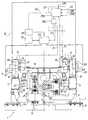
- FIG. 1shows a view in perspective, with parts removed for clarity, of a cable transportation system in accordance with a first embodiment of the present disclosure
- FIG. 2shows a larger-scale front elevation, with parts in section and parts removed for clarity, of the FIG. 1 cable system
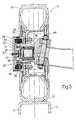
- FIG. 3shows a larger-scale section, with parts removed for clarity, of a detail of a vehicle forming part of the FIG. 1 system;
- FIG. 4shows a plan view, with parts removed for clarity, of a cable transportation system in accordance with a second embodiment of the present disclosure.
- Cable transportation system 1comprises a fixed structure 2 ( FIG. 2 ) for supporting a pair of parallel rails 3 defining an endless transportation path P; a continuous draw cable 4 extending along transportation path P; a drive station 5 for driving draw cable 4 ; a number of vehicles 6 (only one shown in FIG. 1 ) movable along transportation path P and connectable selectively to draw cable 4 ; and a number of passenger stations 7 (only one shown in FIG. 1 ) where each vehicle 6 is stopped cyclically to allow passengers to board and alight from vehicle 6 .
- Passenger station 7comprises a deceleration portion 7 a , of length D, where vehicle 6 is decelerated; a stop position 7 b , where vehicle 6 is stopped; and an acceleration portion 7 c , of length A, where vehicle 6 is accelerated.
- fixed structure 2is anchored to a base 8 , and provides for supporting rails 3 , guiding draw cable 4 by guide rollers 9 and 10 , and supporting a pair of runners 11 extending at passenger station 7 , and which cooperate with vehicle 6 to connect and release vehicle 6 to and from draw cable 4 .
- Each rail 3has a top supporting face 12 and an inner lateral supporting face 13 .
- the two runners 11extend along path P, between the two rails 3 , at deceleration portion 7 a and acceleration portion 7 c , as described in Patent EP 0687 607 B1.
- the stop position 7 b separating deceleration portion 7 a and acceleration portion 7 cis defined with a narrow tolerance of about 20 cm (or 7.87 inches).
- Drive station 5comprises a winch 14 of axis A 1 ; and an electric motor 15 for rotating winch 14 about axis A 1 continuously at constant speed, and moving draw cable 4 at constant speed along path P.
- vehicle 6comprises a frame 16 ; a number of supporting wheels 17 ; a number of direction wheels 18 ; a cab 19 on top of frame 16 ; and a coupling device 20 for connection to draw cable 4 .
- Coupling device 20is of the type described in Patent EP 0687 607 B1, and cooperates with the two runners 11 at each passenger station 7 as described in Patent EP 0687 607 B1.
- vehicle 6For each supporting wheel 17 , vehicle 6 comprises an electric machine 21 , which acts as a generator, motor, and brake. Vehicle 6 comprises a selector 22 for modulating electric power flow; an electric power accumulator 23 ; an electric user device 24 ; and a control unit 25 , in turn comprising a computing module 25 B and a regulating module 25 C.
- Each wheel 17is directional, rotates about a horizontal axis A 2 , and comprises a tire 26 resting on the top supporting face 12 of a rail 3 ; and each direction wheel 18 rotates about a vertical axis A 3 , is forced against the inner lateral supporting face 13 of a rail 3 by elastic members (not shown), and is fitted to a movable arm 27 connected to a respective wheel 17 , and which imparts a steering moment to wheel 17 , depending on the position of direction wheel 18 .
- This method of orienting wheels 17is made possible by axis A 3 of direction wheel 18 and axis A 2 of respective wheel 17 lying in different planes.
- each wheel 17comprises a hub 28 supporting a wheel rim 29 , in turn supporting tire 26 , and is mounted to rotate about a pin 30 connected to arm 27 and hinged to frame 16 about a steering axis A 4 .
- a rolling bearing 31is interposed between pin 30 and hub 28 .
- Hub 28comprises an annular portion 32 projecting on the opposite side to frame 16 , and in which is formed a seat for the rotor 33 of electric machine 21 .
- Each wheel 17has a cover 35 formed by two connected flanges 36 and 37 , which enclose an annular stator 38 of electric machine 21 . Cover 35 is fixed to pin 30 , and provides for supporting stator 38 and protecting electric machine 21 from the surrounding environment.
- Stator 38comprises a core 39 of ferromagnetic material, and an electric winding 40 supported by core 39 .
- the rotorextends about the stator.
- vehicle 6comprises a brake 41 at each wheel 17 ; and a speed sensor 42 , which transmits a speed signal SV, related to the instantaneous speed of vehicle 6 , to control unit 25 .
- Cable transportation system 1generates electric power when vehicle 6 is moving, and uses the generated electric power to power user device 24 , which indicates as a whole one or more user devices, such as an interior lighting system of vehicle 6 , and exterior lighting system of vehicle 6 , a heating system of vehicle 6 , an air-conditioning system of vehicle 6 , etc.
- User device 24also represents as a whole a group of different user devices in general, and supplies an absorption signal SA to computing module 25 B.
- electric machines 21 at respective wheels 17generate electric power which is stored in accumulator 23 by selector 22 ; and accumulator 23 powers user device 24 , as required, by selector 22 and under the control of control unit 25 which coordinates operation of selector 22 .
- Electric machines 21operate as generators along the whole of transportation path P, with the exception of the portions at passenger station 7 , where control unit 25 operates electric machines 21 as generators, motors, and brakes, depending on circumstances.
- Electric machines 21 on board vehicle 6 , and brakes 41eliminate the need to install, at each passenger station 7 , the deceleration and acceleration conveyors described in Patent EP 0 687 607 B1.
- vehicle 6is decelerated as follows: once the draw cable is detached from vehicle 6 , vehicle 6 is braked by electric machines 21 , which absorb power by operating as electric power generators, and by the normal rolling friction of wheels 17 and direction wheels 18 on rails 3 . These braking forces, however, do not guarantee stoppage of vehicle 6 at stop position 7 b and at the required speed. Moreover, the mass of vehicle 6 varies, depending on the number of passengers; and other uncontrollable parameters, such as external temperature and humidity, may also affect the forces in play when decelerating vehicle 6 .
- computing module 25 Breceives speed signal SV from sensor 42 , and compares speed signal SV with a deceleration speed curve SVD corresponding to the ideal deceleration speed, as a function of time, from the start of deceleration portion 7 a to stop position 7 b . Whenever speed signal SV exceeds the ideal speed, according to deceleration speed curve SVD, by more than a given acceptance range, control unit 25 transmits an instantaneous actuating signal F 1 to brakes 41 .
- regulating module 25 CWhen speed signal SV falls below the ideal speed by more than the relative acceptance range, regulating module 25 C, under the control of computing module 25 B, emits an actuating signal F 2 to instantaneously operate at least one electric machine 21 as a motor.
- the instantaneous speed SV of vehicle 6is compared repeatedly with deceleration speed curve SVD and acceleration speed curve SVA, and, by successive adjustments, control unit 25 guides vehicle 6 into stop position 7 b . Once the passengers have alighted or boarded, vehicle 6 is ready to depart.
- vehicle 6is braked solely by electric machines 21 operating as brakes. That is, when speed SV of vehicle 6 is greater than deceleration speed SVD, regulating module 25 C, in accordance with instructions from computing module 25 B, transmits a signal F 2 to selector 22 , which increases the electric absorption, and hence the braking force, of electric machines 21 . Regulating the braking force of electric machines 21 allows brakes 41 to be omitted. Alternatively, electric machines 21 brake vehicle 6 together with brakes 41 .
- electric machines 21may be used to advantage as emergency brakes: computing unit 25 B is supplied by the control system (not shown) of cable transportation system 1 with a signal SRC relating to the integrity of draw cable 4 .
- signal SRCassumes a value indicating failure of draw cable 4
- the computing moduletransmits a signal to regulating module 25 C, which, by means of signal F 2 , sets selector 22 to maximum absorption (resistance) to enable electric machines 21 as brakes—in this case, as emergency brakes.
- selector 22can be operated as a power dissipater.
- the start signal to start vehicle 6is received by control unit 25 from the control system (not shown) of cable transportation system 1 ; and, on receiving the start signal, control unit 25 commands selector 22 to power all the electric machines 21 as motors.
- computing module 25 Bcompares vehicle speed SV with an ideal acceleration speed curve SVA, calculated as a function of the speed SC of the cable, and accelerates or decelerates vehicle 6 by adjusting power supply to electric machines 21 , depending on the deviation of speed signal SV with respect to acceleration speed curve SVA and the relative acceptance range. Vehicle 6 is thus brought to substantially the same speed as speed SC of draw cable 4 by the end of portion 7 c , and can therefore be connected smoothly to draw cable 4 .
- the power supplied on board vehicle 6is substantially that transmitted to draw cable 4 in the form of kinetic energy at drive station 5 and temporarily stored in accumulator 23 for use in accelerating vehicle 6 .
- This poweris supplied to user device 24 , fed back to wheels 17 as drive power, and, if necessary, dissipated when operating electric machine 21 as a brake.
- number 43indicates a passenger “to-and-fro” cable transportation system, which comprises two parallel rails 44 defining a straight transportation path P 1 ; a continuous draw cable 45 extending along transportation path P 1 ; a drive station 46 for driving draw cable 45 ; a vehicle 47 movable along transportation path P 1 and connected to draw cable 45 ; and two passenger stations 48 located at opposite ends of transportation path P 1 , and where vehicle 47 is stopped to allow passengers to board and alight from vehicle 47 .
- Drive station 46comprises a winch 49 about axis A 5 ; and an electric motor 50 for rotating winch 49 about axis A 5 , and moving draw cable 45 along path P 1 .
- Vehicle 47is reversed and stopped at passenger stations 48 by winch 49 .
- Vehicle 47is equipped with an electric machine 21 of the type described with reference to the first embodiment of the present disclosure, and which acts as a current generator, and, in the event of failure of draw cable 45 , as an emergency brake and as a motor to return vehicle 47 to passenger station 48 .
- the component partsare substantially the same as in the first embodiment, and operation differs solely as regards selective connection to the draw cable.
- brake and motor operation of electric machine 21assists operation of draw cable 45 .
Landscapes
- Engineering & Computer Science (AREA)
- Mechanical Engineering (AREA)
- Transportation (AREA)
- Life Sciences & Earth Sciences (AREA)
- Sustainable Development (AREA)
- Sustainable Energy (AREA)
- Power Engineering (AREA)
- Electric Propulsion And Braking For Vehicles (AREA)
- Platform Screen Doors And Railroad Systems (AREA)
- Load-Engaging Elements For Cranes (AREA)
- Ropes Or Cables (AREA)
- Electric Cable Arrangement Between Relatively Moving Parts (AREA)
Abstract
Description
Claims (8)
Applications Claiming Priority (4)
| Application Number | Priority Date | Filing Date | Title |
|---|---|---|---|
| ITMI2007A0835 | 2007-04-20 | ||
| IT000835AITMI20070835A1 (en) | 2007-04-20 | 2007-04-20 | ROPE TRANSPORTATION SYSTEM AND METHOD OF OPERATION OF THE SAME |
| ITMI2007A000835 | 2007-04-20 | ||
| PCT/EP2008/054774WO2008129019A1 (en) | 2007-04-20 | 2008-04-18 | Rail transportation system with releasable haulage cable and relative drive method |
Related Parent Applications (1)
| Application Number | Title | Priority Date | Filing Date |
|---|---|---|---|
| PCT/EP2008/054774A-371-Of-InternationalWO2008129019A1 (en) | 2007-04-20 | 2008-04-18 | Rail transportation system with releasable haulage cable and relative drive method |
Related Child Applications (1)
| Application Number | Title | Priority Date | Filing Date |
|---|---|---|---|
| US14/486,657ContinuationUS9463811B2 (en) | 2007-04-20 | 2014-09-15 | Cable transportation system and relative drive method |
Publications (2)
| Publication Number | Publication Date |
|---|---|
| US20100180792A1 US20100180792A1 (en) | 2010-07-22 |
| US8844446B2true US8844446B2 (en) | 2014-09-30 |
Family
ID=39673202
Family Applications (2)
| Application Number | Title | Priority Date | Filing Date |
|---|---|---|---|
| US12/596,801Active2029-12-11US8844446B2 (en) | 2007-04-20 | 2008-04-18 | Cable transportation system and relative drive method |
| US14/486,657Active2028-08-04US9463811B2 (en) | 2007-04-20 | 2014-09-15 | Cable transportation system and relative drive method |
Family Applications After (1)
| Application Number | Title | Priority Date | Filing Date |
|---|---|---|---|
| US14/486,657Active2028-08-04US9463811B2 (en) | 2007-04-20 | 2014-09-15 | Cable transportation system and relative drive method |
Country Status (7)
| Country | Link |
|---|---|
| US (2) | US8844446B2 (en) |
| EP (1) | EP2148801B2 (en) |
| AT (1) | ATE550237T2 (en) |
| ES (1) | ES2383625T5 (en) |
| IT (1) | ITMI20070835A1 (en) |
| PT (1) | PT2148801E (en) |
| WO (1) | WO2008129019A1 (en) |
Cited By (2)
| Publication number | Priority date | Publication date | Assignee | Title |
|---|---|---|---|---|
| US10727674B2 (en) | 2015-03-19 | 2020-07-28 | Innova Patent Gmbh | System for supplying at least one electrical load or energy storage device with direct current |
| US11027754B2 (en)* | 2017-07-27 | 2021-06-08 | Vinci Construction | Cable or similar transport installation, and vehicle suitable for such installation |
Families Citing this family (23)
| Publication number | Priority date | Publication date | Assignee | Title |
|---|---|---|---|---|
| ITBZ20030005A1 (en) | 2003-01-30 | 2004-07-31 | High Technology Invest Bv | PRESSER DEVICE FOR CONDUCTING ROPE IN ROPE TRACTION TRANSPORT SYSTEMS. |
| ITBZ20050051A1 (en) | 2005-09-29 | 2007-03-30 | High Technology Invest Bv | ANTI-SCROLL-UP DEVICE FOR FUNPOSAL SYSTEM ROPES. |
| ITMI20070157U1 (en) | 2007-04-20 | 2008-10-21 | Rolic Invest Sarl | CHAIRLIFT |
| ITMI20071618A1 (en) | 2007-08-03 | 2009-02-04 | Rolic Invest Sarl | ROPE TRANSPORTATION SYSTEM AND METHOD OF OPERATION OF THE SAME |
| ITMI20072071A1 (en) | 2007-10-26 | 2009-04-27 | Rolic Invest Sarl | ROPE TRANSPORTATION SYSTEM AND METHOD OF OPERATION OF THE SAME |
| IT1395098B1 (en) | 2009-07-09 | 2012-09-05 | Rolic Invest Sarl | TRANSPORT UNIT FOR ROPE TRANSPORT SYSTEMS |
| IT1395737B1 (en) | 2009-08-04 | 2012-10-19 | Rolic Invest Sarl | RECALL OF A SEAT FOR SKILIFT |
| IT1401120B1 (en) | 2010-07-14 | 2013-07-12 | Rolic Invest Sarl | EXCHANGE FOR ROPE TRANSPORTATION SYSTEM AND ROPE TRANSPORTATION SYSTEM INCLUDING SUCH EXCHANGE. |
| AT512298B1 (en)* | 2012-02-06 | 2013-07-15 | Innova Patent Gmbh | ROLE, IN PARTICULAR ROLLER BZW. CARRIER FOR RAILWAY SYSTEMS |
| FR2993227B1 (en)* | 2012-07-10 | 2015-10-30 | Pomagalski Sa | CABLE TRANSPORTATION INSTALLATION |
| ITMI20130308A1 (en) | 2013-02-28 | 2014-08-29 | Rolic Internat S A R L | EXCHANGE FOR A ROPE TRANSPORTATION SYSTEM |
| ITMI20130309A1 (en) | 2013-02-28 | 2014-08-29 | Rolic Internat S A R L | ROPE TRANSPORTATION SYSTEM FOR ADVANCED TRANSPORT UNIT ALONG A DETERMINED TRACK |
| ITMI20130609A1 (en)* | 2013-04-12 | 2014-10-13 | Rolic Internat S A R L | TROLLEY FOR ROPE TRANSPORTATION SYSTEMS AND ROPE TRANSPORTATION SYSTEM INCLUDING THIS TROLLEY |
| ITMI20130741A1 (en) | 2013-05-07 | 2014-11-08 | Rolic Internat S A R L | ROPE TRANSPORTATION SYSTEM FOR ADVANCED TRANSPORT UNIT ALONG A DETERMINED TRACK |
| TW201525283A (en)* | 2013-12-30 | 2015-07-01 | Jun Fu Clean Energy Co Ltd | Circulating power plant |
| WO2015166357A1 (en) | 2014-05-02 | 2015-11-05 | Dimensione Ingenierie S.R.L. | A continuously moving cableway |
| WO2018039507A1 (en)* | 2016-08-25 | 2018-03-01 | Kinkead Jordan | Rail transportation system |
| US11097750B2 (en)* | 2017-12-22 | 2021-08-24 | Leitner S.P.A. | Cable transportation system and method for transporting people or goods and clamp for a vehicle of a cable transportation system |
| US10784744B2 (en)* | 2018-08-10 | 2020-09-22 | Russell Wayne Crawford | Gravity line power generation system including an overhead trolley mechanism to harvest kinetic energy from a wheeled vehicle moving down a slope |
| EP3978302A1 (en)* | 2020-10-01 | 2022-04-06 | Bartholet Maschinenbau AG | Cableway system and method for operating same |
| US11565884B1 (en) | 2021-12-01 | 2023-01-31 | Cooley Enterprises, LLC | Clean energy integrated transportation system using a track and cable |
| US11827249B2 (en) | 2021-12-01 | 2023-11-28 | Cooley Enterprises, LLC | Clean energy integrated transportation system using a hydro system |
| US11390470B1 (en)* | 2021-12-01 | 2022-07-19 | Cooley Enterprises, LLC | Clean energy integrated transportation system |
Citations (94)
| Publication number | Priority date | Publication date | Assignee | Title |
|---|---|---|---|---|
| US472211A (en) | 1892-04-05 | Half to louis a | ||
| DE423865C (en) | 1925-02-28 | 1926-01-12 | Karl Laissle Dipl Ing | Rope carrying device |
| US1944446A (en) | 1932-05-27 | 1934-01-23 | Mckay Co | Swing |
| FR891743A (en) | 1941-11-25 | 1944-03-17 | Pohlig J Ag | Control for cable cars |
| FR913146A (en) | 1945-08-06 | 1946-08-29 | Multi-skip cable car, continuous operation, for travelers | |
| CH259291A (en) | 1947-02-21 | 1949-01-15 | Eisen Und Stahlwerke Oehler & | Safety device on suspension railway systems. |
| US2662587A (en) | 1949-11-18 | 1953-12-15 | Mcilvaine Alexander | Chair for aerial skilifts |
| US2710650A (en) | 1954-03-19 | 1955-06-14 | Riblet Tramway Company | Aerial ski lift chair |
| FR1100001A (en) | 1954-02-19 | 1955-09-15 | Air Carrier Improvements | |
| FR1199721A (en) | 1958-06-20 | 1959-12-16 | Upgrades to Cable Carriers | |
| US2985224A (en) | 1958-03-28 | 1961-05-23 | Riblet Tramway Company | Aerial lift passenger chair |
| CH360704A (en) | 1960-03-15 | 1962-03-15 | Mayor Henry | Safety device for an air carrier cable |
| US3170412A (en) | 1963-05-06 | 1965-02-23 | Ribiet Tramway Company | Chair swing damper |
| FR1423648A (en) | 1963-05-10 | 1966-01-07 | Doppelmayr & Sohn | Safety device for ropeways, in particular for single-cable ropeways |
| GB1242749A (en) | 1967-08-25 | 1971-08-11 | George Crompton | Electrically driven locomotive |
| DE2020746A1 (en) | 1970-04-28 | 1971-12-02 | Fritz Leh | Cable guide station for rail-bound transport systems, especially for mining companies |
| DE2101743A1 (en) | 1971-01-15 | 1972-09-07 | Maschinenfabrik Scharf Gmbh, 4700 Hamm | Roller block with a controlled forced guidance for the pull rope of a cableway laid in particular in mining conveyor lines |
| GB1326264A (en) | 1969-10-29 | 1973-08-08 | Krampe Co Fertigund In Bergbau | Railway track and vehicles for use in underground mining |
| AT315910B (en) | 1970-08-21 | 1974-06-25 | Waagner Biro Ag | Pull rope vibration damper |
| CH554761A (en) | 1972-11-03 | 1974-10-15 | Streiff Mathias | DEVICE FOR FASTENING PULL ROPE ROLLERS, TRAILER AND / OR GUIDE RAILS AND STAIRS TO RAMP OF FUNCTIONAL RAILWAYS. |
| US3934517A (en) | 1973-11-20 | 1976-01-27 | Willy Habegger | Cable connection with slack cable-brake release for an aerial cableway |
| GB1460106A (en) | 1974-05-22 | 1976-12-31 | Coal Industry Patents Ltd | Method of propulsion of vehicles |
| FR2340895A1 (en) | 1976-02-12 | 1977-09-09 | Pomagalski Sa | Support guide for ski hoist cable - has two pairs of rollers with tyres angled to contact at top and support cable but pass tow brackets |
| AT342655B (en) | 1976-06-14 | 1978-04-10 | Waagner Biro Ag | ROPE VIBRATION DAMPER FOR ROPE SYSTEMS |
| FR2387830A1 (en) | 1977-04-22 | 1978-11-17 | Pomagalski Sa | Monorail cable railway roller safety mechanism - has cutters activated by rockers to cut wire and break electric circuit |
| FR2391450A1 (en) | 1977-05-18 | 1978-12-15 | Stgm | Position of traction cable checking system - uses probe signalling when cable derailment on balancing pulley assembly occurs |
| FR2392858A1 (en) | 1977-05-12 | 1978-12-29 | Mautino Victor | Haulage and supporting rope roller set - has support rocker with eye at end to receive end rope which is tensioned by spring |
| GB2017024A (en) | 1978-03-16 | 1979-10-03 | Scharf Gmbh Maschf | Cable-operated conveyor |
| US4185562A (en) | 1976-08-31 | 1980-01-29 | Nissan Motor Company, Limited | Suspended driving railway car |
| US4226187A (en) | 1978-10-23 | 1980-10-07 | Sdi Welding Corporation | Ski lift apparatus and safety device |
| US4269123A (en) | 1978-02-01 | 1981-05-26 | Pomagalski S.A. | Safety device for a rocker of sheaves supporting an overhead cable |
| US4280411A (en) | 1979-01-25 | 1981-07-28 | Nissan Motor Company, Limited | Aerial car suspension |
| EP0055955A1 (en) | 1980-12-22 | 1982-07-14 | Pomagalski S.A. | Cableway with support cable and haulage cable |
| DE3109294A1 (en) | 1981-03-11 | 1982-10-14 | Muckenhaupt GmbH, 4320 Hattingen | Conveyor system with traction cable for underground mining operations |
| AT373832B (en) | 1981-04-21 | 1984-02-27 | Nejez Josef Dipl Ing Dr Techn | SAFETY DEVICE FOR MONITORING THE ROPE OF EARTHED CONDUCTOR ROPES ON ROLLER BATTERIES OF CABLE CARS AND TOW LIFTS |
| US4462314A (en) | 1982-02-05 | 1984-07-31 | Kunczynski Jan K | Rocker arm assembly for an aerial tramway |
| US4470355A (en) | 1977-11-14 | 1984-09-11 | Kunczynski Jan K | Pneumatic cable tensioning apparatus and method for an aerial tramway or the like |
| US4473011A (en) | 1981-03-14 | 1984-09-25 | Phb Weserhutte Ag | Circulating aerial ropeway and car therefor |
| EP0135239A2 (en) | 1983-09-16 | 1985-03-27 | LEITNER S.p.A. | Progressively acting hauling device for ski-lifts, with centrifugal brake |
| FR2562857A1 (en) | 1984-04-13 | 1985-10-18 | Pomagalski Sa | BALANCERS OF AN AIR CABLE TRANSPORTATION SYSTEM |
| US4641587A (en) | 1983-07-04 | 1987-02-10 | Ateliers De Constructions Mecaniques De Vevey S.A. | Suspended motorized vehicle |
| EP0218306A2 (en) | 1985-10-09 | 1987-04-15 | LEITNER S.p.A. | Buffered lead-in quide for cableway vehicles |
| EP0218897A2 (en) | 1985-09-11 | 1987-04-22 | KONRAD DOPPELMAYR & SOHN MASCHINENFABRIK GESELLSCHAFT M.B.H. & CO. KG. | Running gear support for aerial cableways, especially for closed-loop single-cable cableways |
| US4671187A (en) | 1985-09-20 | 1987-06-09 | Kunczynski Jan K | Deropement sensor apparatus with gravity-biased, falling, magnetic member |
| EP0281205A2 (en) | 1987-03-06 | 1988-09-07 | LEITNER S.p.A. | Cableway installation with a deflected cable run |
| AT388146B (en) | 1988-01-08 | 1989-05-10 | Engel Edwin Dipl Ing Dr Techn | Method and devices for automatically monitoring the position of the hauling cables of cableways and T-bar lifts on a cable carrying roller |
| DE3834116A1 (en) | 1987-11-04 | 1989-05-24 | Scharf Gmbh Maschf | Arrangement for guiding a traction cable |
| US4833997A (en) | 1986-10-02 | 1989-05-30 | Pomagalski Sa | Bicable aerial transport system operating on two carrier and haulage ropes running on off-set pulleys |
| US4898100A (en) | 1987-03-11 | 1990-02-06 | Pomagalski Sa | Aerial transport installation with two suspension-traction cables and pulleys displaced vertically |
| AT390926B (en) | 1989-03-14 | 1990-07-25 | Swoboda Seilbahnbau Gmbh | Device for monitoring the position of a haulage cable of an aerial cableway or of a draglift on a cable pulley |
| DE3927757C1 (en) | 1989-08-23 | 1991-03-28 | Kloeckner-Becorit Gmbh, 4620 Castrop-Rauxel, De | Wagon rope haulage system - uses single flange rollers on spring-loaded levers |
| US5107771A (en) | 1990-03-08 | 1992-04-28 | Waagner-Biro Aktiengesellschaft | Connection of several cableway cars |
| US5113768A (en) | 1991-03-15 | 1992-05-19 | Brown Garrett W | Cable-suspended apparatus for supporting a stabilized camera assembly |
| FR2670452A1 (en) | 1990-12-18 | 1992-06-19 | Pomagalski Sa | Device for damping out the oscillations in the hauling cable of a ropeway (cableway, telepherique) |
| EP0491632A1 (en) | 1990-12-18 | 1992-06-24 | Pomagalski S.A. | Disengageable telpher carrier or chairlift with two cable loops |
| EP0517622A1 (en) | 1991-06-03 | 1992-12-09 | Pomagalski S.A. | Safety device for a transporting plant with aerial cable |
| EP0613807A1 (en) | 1991-11-29 | 1994-09-07 | Seiko Epson Corporation | Displacement in transfer apparatus and driving controller of transfer member |
| FR2706404A1 (en) | 1993-06-09 | 1994-12-23 | Montagner Rene | Ski-lift installation |
| EP0640518A1 (en) | 1993-08-25 | 1995-03-01 | Pomagalski S.A. | Stabilization device for the grips of a ropeway |
| US5465806A (en) | 1989-03-31 | 1995-11-14 | Kabushiki Kaisha Shikoku Sogo Kenkyujo | Electric vehicle |
| EP0687607A1 (en) | 1994-06-16 | 1995-12-20 | LEITNER S.p.A. | Funicular system of rail and running cable type, in particular for urban transport, of the type in which the vehicles are provided with a movable jaw clamp for their coupling to and release from said running cable |
| EP0692418A1 (en) | 1994-07-14 | 1996-01-17 | HOELZL COSTRUZIONE FUNIVIE s.r.l. | Driving system for cableway installations of the type including carrying cables and hauling cables |
| US5517923A (en)* | 1994-04-22 | 1996-05-21 | Pomagalski S.A. | Cable drawn vehicle having an on-board motor |
| US5562040A (en) | 1994-03-11 | 1996-10-08 | Garaventa Holding Ag | Rope guide system for an aerial ropeway, particularly a circuital aerial ropeway |
| EP0745526A1 (en) | 1995-05-29 | 1996-12-04 | Girak Garaventa GmbH | Mechanical protection against cable derailment |
| US5582109A (en)* | 1994-06-16 | 1996-12-10 | Leitner S.P.A. | Double-acting clamp for coupling a funicular vehicle to the running cable |
| DE19756904A1 (en) | 1996-12-20 | 1998-06-25 | Whitaker Corp Wilmington | Electrical power device for mounting on an axis |
| EP0970864A2 (en) | 1998-07-09 | 2000-01-12 | Von Roll Seilbahnen AG | Bearing device for a suport cable |
| EP1077167A1 (en) | 1999-08-18 | 2001-02-21 | LEITNER S.p.A. | Improved mobile jaw vice for clamping and unclamping vehicles to and from a traction cable of a transport system |
| EP1088729A1 (en) | 1999-10-01 | 2001-04-04 | High Technology Investments B.V. | Constrained guide urban transport system |
| EP1174323A2 (en) | 2000-07-20 | 2002-01-23 | Innova Patent GmbH | Passenger transport installation |
| US6345578B1 (en) | 1999-09-24 | 2002-02-12 | High Technology Investments B.V. | Double-acting trolley to support one-cable installations and in particular chair lifts and cabin lifts |
| US20020026839A1 (en) | 1997-11-26 | 2002-03-07 | Litens Automotive Partnership | Load sensor |
| EP1195305A1 (en) | 2000-10-04 | 2002-04-10 | Garaventa Holding Ag | Method and device for closing a hood for a chair lift |
| EP1209055A1 (en) | 2000-11-27 | 2002-05-29 | High Technology Investments B.V. | Counteracting roller arrangement for a cableway installation |
| FR2823482A1 (en) | 2001-04-11 | 2002-10-18 | Pomagalski Sa | Cableway transport system support and guide has two sets of rollers on curved beam pivoted to pylon |
| US6543366B2 (en) | 2000-11-27 | 2003-04-08 | High Technology Investments Bv | Continuously moving cable traction haulage system with vehicles equipped with disengageable coupling clamps |
| US6585232B2 (en) | 2000-01-21 | 2003-07-01 | Leitner S.P.A. | Device for setting and automatic adjustment of the tractive force of a cable of an overhead winch for a ski slope preparation and maintenance machine |
| EP1331151A1 (en) | 2002-01-24 | 2003-07-30 | Innova Patent GmbH | Chair for an aerial ropeway |
| US6615118B2 (en)* | 2001-03-27 | 2003-09-02 | General Electric Company | Hybrid energy power management system and method |
| EP1364853A1 (en) | 2002-05-22 | 2003-11-26 | Pomagalski S.A. | Support and guiding device for the cable of a transport system |
| WO2004067347A1 (en) | 2003-01-30 | 2004-08-12 | High Technology Investments B.V. | Hold-down device for the cable guide in cable-drawn transport systems |
| WO2004085221A1 (en) | 2003-03-26 | 2004-10-07 | Edwin Engel | Device and method for capturing a traction rope of an aerial ropeway or a t bar |
| WO2005032901A1 (en) | 2003-10-03 | 2005-04-14 | High Technology Investments B.V. | Damping device for traction ropes of cable cars |
| FR2867142A1 (en) | 2004-03-08 | 2005-09-09 | Pomagalski Sa | Carrying traction rope supporting and guiding mechanical device for chair or gondola lift type ski lift, has elastic coupling connection to create pseudo-articulation within each of two bogies |
| US20060249718A1 (en) | 2005-05-03 | 2006-11-09 | High Technology Investments B.V. | Moving system for a cableway plant comprising two hauling cables |
| WO2008020021A1 (en) | 2006-08-16 | 2008-02-21 | High Technology Investments B.V. | Chair-lift chair safety device with a crossbar lock-release control device |
| DE102006040220A1 (en) | 2006-08-28 | 2008-03-20 | Franc Just | Hub motor e.g. direct current electric motor, for use in e.g. mobile transport chair, has magnet coils, whose section, which is immersed in air gap, is aligned parallel to rotary axis of hub motor |
| US7410068B1 (en) | 2007-07-06 | 2008-08-12 | Agudio S.P.A. | Blondin cableway installation |
| WO2008129017A1 (en) | 2007-04-20 | 2008-10-30 | Rolic Invest Sarl | Chair-lift |
| WO2009019259A1 (en) | 2007-08-03 | 2009-02-12 | Rolic Invest Sarl | Cable transportation system and relative operating method |
| WO2009053485A2 (en) | 2007-10-26 | 2009-04-30 | Rolic Invest S.Ar.L | Cable transportation system and relative operating method |
| US20090165666A1 (en) | 2005-09-29 | 2009-07-02 | High Technology Investiments B.V. | Cable derailing prevention device for carrier/traction cables of cable car systems |
| US20090165668A1 (en) | 2007-12-28 | 2009-07-02 | Rolic Invest S.Ar.L. | Cableway system with supporting and haul cables |
Family Cites Families (4)
| Publication number | Priority date | Publication date | Assignee | Title |
|---|---|---|---|---|
| DE1588622C3 (en)† | 1967-05-03 | 1980-02-14 | Pintsch Bamag Antriebs- Und Verkehrstechnik Gmbh, 4220 Dinslaken | Generator without slip rings for controlling auxiliary equipment of a rail vehicle |
| CH564445A5 (en)† | 1973-07-20 | 1975-07-31 | Vevey Atel Const Mec | Electrical generator used on railway carriages - is assembled in annular space between wheel and axle uses permanent magnet |
| DE4127373A1 (en)* | 1991-08-19 | 1993-02-25 | Wolf Von Bodisco | Suspended railway allowing continuous, frequent flow of transporting cabins - uses bidirectional cabins crossing at stations and having ceiling-mounted clamp arms gripping motor-driven rope loop |
| EP1419950A1 (en)* | 2002-11-14 | 2004-05-19 | Innova Patent GmbH | Rope railway with swivelling cabins or seats |
- 2007
- 2007-04-20ITIT000835Apatent/ITMI20070835A1/enunknown
- 2008
- 2008-04-18ESES08736407Tpatent/ES2383625T5/enactiveActive
- 2008-04-18PTPT08736407Tpatent/PT2148801E/enunknown
- 2008-04-18EPEP08736407.1Apatent/EP2148801B2/enactiveActive
- 2008-04-18WOPCT/EP2008/054774patent/WO2008129019A1/enactiveApplication Filing
- 2008-04-18ATAT08736407Tpatent/ATE550237T2/enactive
- 2008-04-18USUS12/596,801patent/US8844446B2/enactiveActive
- 2014
- 2014-09-15USUS14/486,657patent/US9463811B2/enactiveActive
Patent Citations (103)
| Publication number | Priority date | Publication date | Assignee | Title |
|---|---|---|---|---|
| US472211A (en) | 1892-04-05 | Half to louis a | ||
| DE423865C (en) | 1925-02-28 | 1926-01-12 | Karl Laissle Dipl Ing | Rope carrying device |
| US1944446A (en) | 1932-05-27 | 1934-01-23 | Mckay Co | Swing |
| FR891743A (en) | 1941-11-25 | 1944-03-17 | Pohlig J Ag | Control for cable cars |
| FR913146A (en) | 1945-08-06 | 1946-08-29 | Multi-skip cable car, continuous operation, for travelers | |
| CH259291A (en) | 1947-02-21 | 1949-01-15 | Eisen Und Stahlwerke Oehler & | Safety device on suspension railway systems. |
| US2662587A (en) | 1949-11-18 | 1953-12-15 | Mcilvaine Alexander | Chair for aerial skilifts |
| FR1100001A (en) | 1954-02-19 | 1955-09-15 | Air Carrier Improvements | |
| US2710650A (en) | 1954-03-19 | 1955-06-14 | Riblet Tramway Company | Aerial ski lift chair |
| US2985224A (en) | 1958-03-28 | 1961-05-23 | Riblet Tramway Company | Aerial lift passenger chair |
| FR1199721A (en) | 1958-06-20 | 1959-12-16 | Upgrades to Cable Carriers | |
| CH360704A (en) | 1960-03-15 | 1962-03-15 | Mayor Henry | Safety device for an air carrier cable |
| US3170412A (en) | 1963-05-06 | 1965-02-23 | Ribiet Tramway Company | Chair swing damper |
| FR1423648A (en) | 1963-05-10 | 1966-01-07 | Doppelmayr & Sohn | Safety device for ropeways, in particular for single-cable ropeways |
| GB1242749A (en) | 1967-08-25 | 1971-08-11 | George Crompton | Electrically driven locomotive |
| GB1326264A (en) | 1969-10-29 | 1973-08-08 | Krampe Co Fertigund In Bergbau | Railway track and vehicles for use in underground mining |
| DE2020746A1 (en) | 1970-04-28 | 1971-12-02 | Fritz Leh | Cable guide station for rail-bound transport systems, especially for mining companies |
| GB1353030A (en) | 1970-04-28 | 1974-05-15 | Leh F | Rope guiding apparatus suitable for a conveyor comprising rail guides vehicles |
| AT315910B (en) | 1970-08-21 | 1974-06-25 | Waagner Biro Ag | Pull rope vibration damper |
| DE2101743A1 (en) | 1971-01-15 | 1972-09-07 | Maschinenfabrik Scharf Gmbh, 4700 Hamm | Roller block with a controlled forced guidance for the pull rope of a cableway laid in particular in mining conveyor lines |
| CH554761A (en) | 1972-11-03 | 1974-10-15 | Streiff Mathias | DEVICE FOR FASTENING PULL ROPE ROLLERS, TRAILER AND / OR GUIDE RAILS AND STAIRS TO RAMP OF FUNCTIONAL RAILWAYS. |
| US3934517A (en) | 1973-11-20 | 1976-01-27 | Willy Habegger | Cable connection with slack cable-brake release for an aerial cableway |
| GB1460106A (en) | 1974-05-22 | 1976-12-31 | Coal Industry Patents Ltd | Method of propulsion of vehicles |
| FR2340895A1 (en) | 1976-02-12 | 1977-09-09 | Pomagalski Sa | Support guide for ski hoist cable - has two pairs of rollers with tyres angled to contact at top and support cable but pass tow brackets |
| AT342655B (en) | 1976-06-14 | 1978-04-10 | Waagner Biro Ag | ROPE VIBRATION DAMPER FOR ROPE SYSTEMS |
| US4185562A (en) | 1976-08-31 | 1980-01-29 | Nissan Motor Company, Limited | Suspended driving railway car |
| FR2387830A1 (en) | 1977-04-22 | 1978-11-17 | Pomagalski Sa | Monorail cable railway roller safety mechanism - has cutters activated by rockers to cut wire and break electric circuit |
| FR2392858A1 (en) | 1977-05-12 | 1978-12-29 | Mautino Victor | Haulage and supporting rope roller set - has support rocker with eye at end to receive end rope which is tensioned by spring |
| FR2391450A1 (en) | 1977-05-18 | 1978-12-15 | Stgm | Position of traction cable checking system - uses probe signalling when cable derailment on balancing pulley assembly occurs |
| US4470355A (en) | 1977-11-14 | 1984-09-11 | Kunczynski Jan K | Pneumatic cable tensioning apparatus and method for an aerial tramway or the like |
| US4269123A (en) | 1978-02-01 | 1981-05-26 | Pomagalski S.A. | Safety device for a rocker of sheaves supporting an overhead cable |
| GB2017024A (en) | 1978-03-16 | 1979-10-03 | Scharf Gmbh Maschf | Cable-operated conveyor |
| US4226187A (en) | 1978-10-23 | 1980-10-07 | Sdi Welding Corporation | Ski lift apparatus and safety device |
| US4280411A (en) | 1979-01-25 | 1981-07-28 | Nissan Motor Company, Limited | Aerial car suspension |
| EP0055955A1 (en) | 1980-12-22 | 1982-07-14 | Pomagalski S.A. | Cableway with support cable and haulage cable |
| DE3109294A1 (en) | 1981-03-11 | 1982-10-14 | Muckenhaupt GmbH, 4320 Hattingen | Conveyor system with traction cable for underground mining operations |
| US4473011A (en) | 1981-03-14 | 1984-09-25 | Phb Weserhutte Ag | Circulating aerial ropeway and car therefor |
| AT373832B (en) | 1981-04-21 | 1984-02-27 | Nejez Josef Dipl Ing Dr Techn | SAFETY DEVICE FOR MONITORING THE ROPE OF EARTHED CONDUCTOR ROPES ON ROLLER BATTERIES OF CABLE CARS AND TOW LIFTS |
| US4462314A (en) | 1982-02-05 | 1984-07-31 | Kunczynski Jan K | Rocker arm assembly for an aerial tramway |
| US4641587A (en) | 1983-07-04 | 1987-02-10 | Ateliers De Constructions Mecaniques De Vevey S.A. | Suspended motorized vehicle |
| EP0135239A2 (en) | 1983-09-16 | 1985-03-27 | LEITNER S.p.A. | Progressively acting hauling device for ski-lifts, with centrifugal brake |
| FR2562857A1 (en) | 1984-04-13 | 1985-10-18 | Pomagalski Sa | BALANCERS OF AN AIR CABLE TRANSPORTATION SYSTEM |
| US4640197A (en) | 1984-04-13 | 1987-02-03 | Pomagalski Sa | Rocker arm assembly with a fixing collar for an aerial tramway installation |
| EP0218897A2 (en) | 1985-09-11 | 1987-04-22 | KONRAD DOPPELMAYR & SOHN MASCHINENFABRIK GESELLSCHAFT M.B.H. & CO. KG. | Running gear support for aerial cableways, especially for closed-loop single-cable cableways |
| US4671187A (en) | 1985-09-20 | 1987-06-09 | Kunczynski Jan K | Deropement sensor apparatus with gravity-biased, falling, magnetic member |
| EP0218306A2 (en) | 1985-10-09 | 1987-04-15 | LEITNER S.p.A. | Buffered lead-in quide for cableway vehicles |
| US4833997A (en) | 1986-10-02 | 1989-05-30 | Pomagalski Sa | Bicable aerial transport system operating on two carrier and haulage ropes running on off-set pulleys |
| EP0281205A2 (en) | 1987-03-06 | 1988-09-07 | LEITNER S.p.A. | Cableway installation with a deflected cable run |
| US4898100A (en) | 1987-03-11 | 1990-02-06 | Pomagalski Sa | Aerial transport installation with two suspension-traction cables and pulleys displaced vertically |
| DE3834116A1 (en) | 1987-11-04 | 1989-05-24 | Scharf Gmbh Maschf | Arrangement for guiding a traction cable |
| AT388146B (en) | 1988-01-08 | 1989-05-10 | Engel Edwin Dipl Ing Dr Techn | Method and devices for automatically monitoring the position of the hauling cables of cableways and T-bar lifts on a cable carrying roller |
| AT390926B (en) | 1989-03-14 | 1990-07-25 | Swoboda Seilbahnbau Gmbh | Device for monitoring the position of a haulage cable of an aerial cableway or of a draglift on a cable pulley |
| US5465806A (en) | 1989-03-31 | 1995-11-14 | Kabushiki Kaisha Shikoku Sogo Kenkyujo | Electric vehicle |
| DE3927757C1 (en) | 1989-08-23 | 1991-03-28 | Kloeckner-Becorit Gmbh, 4620 Castrop-Rauxel, De | Wagon rope haulage system - uses single flange rollers on spring-loaded levers |
| US5107771A (en) | 1990-03-08 | 1992-04-28 | Waagner-Biro Aktiengesellschaft | Connection of several cableway cars |
| FR2670452A1 (en) | 1990-12-18 | 1992-06-19 | Pomagalski Sa | Device for damping out the oscillations in the hauling cable of a ropeway (cableway, telepherique) |
| EP0491632A1 (en) | 1990-12-18 | 1992-06-24 | Pomagalski S.A. | Disengageable telpher carrier or chairlift with two cable loops |
| US5113768A (en) | 1991-03-15 | 1992-05-19 | Brown Garrett W | Cable-suspended apparatus for supporting a stabilized camera assembly |
| EP0517622A1 (en) | 1991-06-03 | 1992-12-09 | Pomagalski S.A. | Safety device for a transporting plant with aerial cable |
| US5226368A (en) | 1991-06-03 | 1993-07-13 | Pomagalski | Safety device for an overhead cable transport installation to ensure proper grip of cable upon coupling |
| EP0613807A1 (en) | 1991-11-29 | 1994-09-07 | Seiko Epson Corporation | Displacement in transfer apparatus and driving controller of transfer member |
| FR2706404A1 (en) | 1993-06-09 | 1994-12-23 | Montagner Rene | Ski-lift installation |
| EP0640518A1 (en) | 1993-08-25 | 1995-03-01 | Pomagalski S.A. | Stabilization device for the grips of a ropeway |
| US5515789A (en) | 1993-08-25 | 1996-05-14 | Pomagalski S.A. | Grip guiding device for aerial cableways |
| US5562040A (en) | 1994-03-11 | 1996-10-08 | Garaventa Holding Ag | Rope guide system for an aerial ropeway, particularly a circuital aerial ropeway |
| US5517923A (en)* | 1994-04-22 | 1996-05-21 | Pomagalski S.A. | Cable drawn vehicle having an on-board motor |
| US5582109A (en)* | 1994-06-16 | 1996-12-10 | Leitner S.P.A. | Double-acting clamp for coupling a funicular vehicle to the running cable |
| EP0687607A1 (en) | 1994-06-16 | 1995-12-20 | LEITNER S.p.A. | Funicular system of rail and running cable type, in particular for urban transport, of the type in which the vehicles are provided with a movable jaw clamp for their coupling to and release from said running cable |
| US5595122A (en)* | 1994-06-16 | 1997-01-21 | Leitner S.P.A. | Funicular system of rail and running cable type |
| EP0692418A1 (en) | 1994-07-14 | 1996-01-17 | HOELZL COSTRUZIONE FUNIVIE s.r.l. | Driving system for cableway installations of the type including carrying cables and hauling cables |
| EP0745526A1 (en) | 1995-05-29 | 1996-12-04 | Girak Garaventa GmbH | Mechanical protection against cable derailment |
| DE19756904A1 (en) | 1996-12-20 | 1998-06-25 | Whitaker Corp Wilmington | Electrical power device for mounting on an axis |
| US20020026839A1 (en) | 1997-11-26 | 2002-03-07 | Litens Automotive Partnership | Load sensor |
| EP0970864A2 (en) | 1998-07-09 | 2000-01-12 | Von Roll Seilbahnen AG | Bearing device for a suport cable |
| EP1077167A1 (en) | 1999-08-18 | 2001-02-21 | LEITNER S.p.A. | Improved mobile jaw vice for clamping and unclamping vehicles to and from a traction cable of a transport system |
| US6345578B1 (en) | 1999-09-24 | 2002-02-12 | High Technology Investments B.V. | Double-acting trolley to support one-cable installations and in particular chair lifts and cabin lifts |
| EP1088729A1 (en) | 1999-10-01 | 2001-04-04 | High Technology Investments B.V. | Constrained guide urban transport system |
| US6585232B2 (en) | 2000-01-21 | 2003-07-01 | Leitner S.P.A. | Device for setting and automatic adjustment of the tractive force of a cable of an overhead winch for a ski slope preparation and maintenance machine |
| EP1174323A2 (en) | 2000-07-20 | 2002-01-23 | Innova Patent GmbH | Passenger transport installation |
| EP1195305A1 (en) | 2000-10-04 | 2002-04-10 | Garaventa Holding Ag | Method and device for closing a hood for a chair lift |
| EP1209055A1 (en) | 2000-11-27 | 2002-05-29 | High Technology Investments B.V. | Counteracting roller arrangement for a cableway installation |
| US20020088368A1 (en) | 2000-11-27 | 2002-07-11 | Otto Pabst | Counter-sheave device for traction cable transportation systems |
| US6543366B2 (en) | 2000-11-27 | 2003-04-08 | High Technology Investments Bv | Continuously moving cable traction haulage system with vehicles equipped with disengageable coupling clamps |
| US6615118B2 (en)* | 2001-03-27 | 2003-09-02 | General Electric Company | Hybrid energy power management system and method |
| FR2823482A1 (en) | 2001-04-11 | 2002-10-18 | Pomagalski Sa | Cableway transport system support and guide has two sets of rollers on curved beam pivoted to pylon |
| EP1331151A1 (en) | 2002-01-24 | 2003-07-30 | Innova Patent GmbH | Chair for an aerial ropeway |
| EP1364853A1 (en) | 2002-05-22 | 2003-11-26 | Pomagalski S.A. | Support and guiding device for the cable of a transport system |
| US20080115689A1 (en) | 2003-01-30 | 2008-05-22 | Ernst Heil | Hold-Down Device For The Cable Guide In Cable-Drawn Transport Systems |
| WO2004067347A1 (en) | 2003-01-30 | 2004-08-12 | High Technology Investments B.V. | Hold-down device for the cable guide in cable-drawn transport systems |
| WO2004085221A1 (en) | 2003-03-26 | 2004-10-07 | Edwin Engel | Device and method for capturing a traction rope of an aerial ropeway or a t bar |
| US7549377B2 (en) | 2003-10-03 | 2009-06-23 | High Technology Investments B.V. | Damper for cableway traction cables |
| WO2005032901A1 (en) | 2003-10-03 | 2005-04-14 | High Technology Investments B.V. | Damping device for traction ropes of cable cars |
| US20070169660A1 (en) | 2003-10-03 | 2007-07-26 | High Technology Investments. B. V. | Damper for cableway traction cables |
| FR2867142A1 (en) | 2004-03-08 | 2005-09-09 | Pomagalski Sa | Carrying traction rope supporting and guiding mechanical device for chair or gondola lift type ski lift, has elastic coupling connection to create pseudo-articulation within each of two bogies |
| US20060249718A1 (en) | 2005-05-03 | 2006-11-09 | High Technology Investments B.V. | Moving system for a cableway plant comprising two hauling cables |
| US20090165666A1 (en) | 2005-09-29 | 2009-07-02 | High Technology Investiments B.V. | Cable derailing prevention device for carrier/traction cables of cable car systems |
| WO2008020021A1 (en) | 2006-08-16 | 2008-02-21 | High Technology Investments B.V. | Chair-lift chair safety device with a crossbar lock-release control device |
| DE102006040220A1 (en) | 2006-08-28 | 2008-03-20 | Franc Just | Hub motor e.g. direct current electric motor, for use in e.g. mobile transport chair, has magnet coils, whose section, which is immersed in air gap, is aligned parallel to rotary axis of hub motor |
| WO2008129017A1 (en) | 2007-04-20 | 2008-10-30 | Rolic Invest Sarl | Chair-lift |
| US7410068B1 (en) | 2007-07-06 | 2008-08-12 | Agudio S.P.A. | Blondin cableway installation |
| WO2009019259A1 (en) | 2007-08-03 | 2009-02-12 | Rolic Invest Sarl | Cable transportation system and relative operating method |
| WO2009053485A2 (en) | 2007-10-26 | 2009-04-30 | Rolic Invest S.Ar.L | Cable transportation system and relative operating method |
| US20090165668A1 (en) | 2007-12-28 | 2009-07-02 | Rolic Invest S.Ar.L. | Cableway system with supporting and haul cables |
Non-Patent Citations (1)
| Title |
|---|
| EPO Notice of Opposition for European Application No. 08736407.1, dated Dec. 14, 2012. |
Cited By (2)
| Publication number | Priority date | Publication date | Assignee | Title |
|---|---|---|---|---|
| US10727674B2 (en) | 2015-03-19 | 2020-07-28 | Innova Patent Gmbh | System for supplying at least one electrical load or energy storage device with direct current |
| US11027754B2 (en)* | 2017-07-27 | 2021-06-08 | Vinci Construction | Cable or similar transport installation, and vehicle suitable for such installation |
Also Published As
| Publication number | Publication date |
|---|---|
| WO2008129019A1 (en) | 2008-10-30 |
| ES2383625T5 (en) | 2020-09-15 |
| WO2008129019A8 (en) | 2009-11-19 |
| US9463811B2 (en) | 2016-10-11 |
| EP2148801B2 (en) | 2019-09-25 |
| US20150000547A1 (en) | 2015-01-01 |
| EP2148801B1 (en) | 2012-03-21 |
| PT2148801E (en) | 2012-06-01 |
| EP2148801A1 (en) | 2010-02-03 |
| ITMI20070835A1 (en) | 2008-10-21 |
| ATE550237T2 (en) | 2012-04-15 |
| ES2383625T3 (en) | 2012-06-22 |
| US20100180792A1 (en) | 2010-07-22 |
Similar Documents
| Publication | Publication Date | Title |
|---|---|---|
| US8844446B2 (en) | Cable transportation system and relative drive method | |
| US5595121A (en) | Amusement ride and self-propelled vehicle therefor | |
| CN100411926C (en) | Transport system | |
| US10315886B2 (en) | Electronic safety actuation device with a power assembly, magnetic brake and electromagnetic component | |
| EP3228573B1 (en) | Electronic safety device with a power assembly | |
| CA2893607A1 (en) | Method for a braking operation of a wheel axle of a rail vehicle and braking system for a rail vehicle | |
| CN105377663A (en) | Rail transit bogies and rail transit systems | |
| JP5189774B2 (en) | Braking energy recovery device and transportation system for track vehicle | |
| JP5533003B2 (en) | Conveyor device | |
| JP6124525B2 (en) | Rescue operation device for rope-drawing transportation equipment | |
| JP4927614B2 (en) | Cable drive pre-drive power supply | |
| US11027754B2 (en) | Cable or similar transport installation, and vehicle suitable for such installation | |
| JP7587864B2 (en) | Transportation System | |
| CN114929545B (en) | Kinetic energy converter for pneumatic transport system | |
| JP3098861B2 (en) | Operation controller for primary linear motor transportation system on the ground | |
| KR101929434B1 (en) | escalator moving with constant speed | |
| KR100459973B1 (en) | Passenger transportation system | |
| JP2012203788A (en) | Carriage travel control system | |
| JP4695162B2 (en) | Transportation equipment | |
| JP6708459B2 (en) | Operation stop control method for rope-towed transportation equipment | |
| HK40030371A (en) | Cable or similar transport installation, and vehicle suitable for such installation | |
| HK40030371B (en) | Cable or similar transport installation, and vehicle suitable for such installation | |
| JP2011162001A (en) | Driving structure, transportation vehicle, and transportation system | |
| KR20110133067A (en) | How to operate trains without stops | |
| JP2017178029A (en) | Operation start control method for cable traction type transportation equipment |
Legal Events
| Date | Code | Title | Description |
|---|---|---|---|
| AS | Assignment | Owner name:ROLIC INVEST S.AR.L., LUXEMBOURG Free format text:ASSIGNMENT OF ASSIGNORS INTEREST;ASSIGNORS:BAVARESCO, FEDERICO;CONTE, GIUSEPPE;REEL/FRAME:024222/0869 Effective date:20100412 | |
| AS | Assignment | Owner name:ROLIC INTERNATIONAL S.AR.L., LUXEMBOURG Free format text:ASSIGNMENT OF ASSIGNORS INTEREST;ASSIGNOR:ROLIC INVEST S.AR.L.;REEL/FRAME:031953/0811 Effective date:20130130 | |
| STCF | Information on status: patent grant | Free format text:PATENTED CASE | |
| AS | Assignment | Owner name:ROPFIN B.V., NETHERLANDS Free format text:ASSIGNMENT OF ASSIGNORS INTEREST;ASSIGNOR:ROLIC INTERNATIONAL S.A R.L.;REEL/FRAME:035255/0271 Effective date:20150127 | |
| AS | Assignment | Owner name:ROPFIN B.V., NETHERLANDS Free format text:CORRECTIVE ASSIGNMENT TO CORRECT THE ASSIGNEE'S ADDRESS PREVIOUSLY RECORDED AT REEL: 035255 FRAME: 0271. ASSIGNOR(S) HEREBY CONFIRMS THE ASSIGNMENT;ASSIGNOR:ROLIC INTERNATIONAL S.A R.L.;REEL/FRAME:035479/0339 Effective date:20150127 | |
| AS | Assignment | Owner name:LEITNER S.P.A., ITALY Free format text:ASSIGNMENT OF ASSIGNORS INTEREST;ASSIGNOR:ROPFIN B.V.;REEL/FRAME:045360/0357 Effective date:20180104 | |
| MAFP | Maintenance fee payment | Free format text:PAYMENT OF MAINTENANCE FEE, 4TH YEAR, LARGE ENTITY (ORIGINAL EVENT CODE: M1551) Year of fee payment:4 | |
| MAFP | Maintenance fee payment | Free format text:PAYMENT OF MAINTENANCE FEE, 8TH YEAR, LARGE ENTITY (ORIGINAL EVENT CODE: M1552); ENTITY STATUS OF PATENT OWNER: LARGE ENTITY Year of fee payment:8 |