US8844073B2 - Apparatus for supporting and monitoring a person - Google Patents
Apparatus for supporting and monitoring a personDownload PDFInfo
- Publication number
- US8844073B2 US8844073B2US13/153,592US201113153592AUS8844073B2US 8844073 B2US8844073 B2US 8844073B2US 201113153592 AUS201113153592 AUS 201113153592AUS 8844073 B2US8844073 B2US 8844073B2
- Authority
- US
- United States
- Prior art keywords
- person
- status
- support structure
- input signal
- function
- Prior art date
- Legal status (The legal status is an assumption and is not a legal conclusion. Google has not performed a legal analysis and makes no representation as to the accuracy of the status listed.)
- Active, expires
Links
Images


Classifications
- A—HUMAN NECESSITIES
- A61—MEDICAL OR VETERINARY SCIENCE; HYGIENE
- A61B—DIAGNOSIS; SURGERY; IDENTIFICATION
- A61B5/00—Measuring for diagnostic purposes; Identification of persons
- A61B5/72—Signal processing specially adapted for physiological signals or for diagnostic purposes
- A61B5/7271—Specific aspects of physiological measurement analysis
- A61B5/7275—Determining trends in physiological measurement data; Predicting development of a medical condition based on physiological measurements, e.g. determining a risk factor
- A—HUMAN NECESSITIES
- A61—MEDICAL OR VETERINARY SCIENCE; HYGIENE
- A61B—DIAGNOSIS; SURGERY; IDENTIFICATION
- A61B5/00—Measuring for diagnostic purposes; Identification of persons
- A61B5/02—Detecting, measuring or recording for evaluating the cardiovascular system, e.g. pulse, heart rate, blood pressure or blood flow
- A61B5/0205—Simultaneously evaluating both cardiovascular conditions and different types of body conditions, e.g. heart and respiratory condition
- A61B5/02055—Simultaneously evaluating both cardiovascular condition and temperature
- A—HUMAN NECESSITIES
- A61—MEDICAL OR VETERINARY SCIENCE; HYGIENE
- A61B—DIAGNOSIS; SURGERY; IDENTIFICATION
- A61B5/00—Measuring for diagnostic purposes; Identification of persons
- A61B5/103—Measuring devices for testing the shape, pattern, colour, size or movement of the body or parts thereof, for diagnostic purposes
- A61B5/11—Measuring movement of the entire body or parts thereof, e.g. head or hand tremor or mobility of a limb
- A61B5/1113—Local tracking of patients, e.g. in a hospital or private home
- A—HUMAN NECESSITIES
- A61—MEDICAL OR VETERINARY SCIENCE; HYGIENE
- A61B—DIAGNOSIS; SURGERY; IDENTIFICATION
- A61B5/00—Measuring for diagnostic purposes; Identification of persons
- A61B5/41—Detecting, measuring or recording for evaluating the immune or lymphatic systems
- A61B5/411—Detecting or monitoring allergy or intolerance reactions to an allergenic agent or substance
- A—HUMAN NECESSITIES
- A61—MEDICAL OR VETERINARY SCIENCE; HYGIENE
- A61B—DIAGNOSIS; SURGERY; IDENTIFICATION
- A61B5/00—Measuring for diagnostic purposes; Identification of persons
- A61B5/68—Arrangements of detecting, measuring or recording means, e.g. sensors, in relation to patient
- A61B5/6887—Arrangements of detecting, measuring or recording means, e.g. sensors, in relation to patient mounted on external non-worn devices, e.g. non-medical devices
- A61B5/6891—Furniture
- A—HUMAN NECESSITIES
- A61—MEDICAL OR VETERINARY SCIENCE; HYGIENE
- A61G—TRANSPORT, PERSONAL CONVEYANCES, OR ACCOMMODATION SPECIALLY ADAPTED FOR PATIENTS OR DISABLED PERSONS; OPERATING TABLES OR CHAIRS; CHAIRS FOR DENTISTRY; FUNERAL DEVICES
- A61G7/00—Beds specially adapted for nursing; Devices for lifting patients or disabled persons
- A61G7/002—Beds specially adapted for nursing; Devices for lifting patients or disabled persons having adjustable mattress frame
- A61G7/018—Control or drive mechanisms
- G06F19/3406—
- G06F19/3418—
- G06F19/3431—
- G—PHYSICS
- G16—INFORMATION AND COMMUNICATION TECHNOLOGY [ICT] SPECIALLY ADAPTED FOR SPECIFIC APPLICATION FIELDS
- G16H—HEALTHCARE INFORMATICS, i.e. INFORMATION AND COMMUNICATION TECHNOLOGY [ICT] SPECIALLY ADAPTED FOR THE HANDLING OR PROCESSING OF MEDICAL OR HEALTHCARE DATA
- G16H10/00—ICT specially adapted for the handling or processing of patient-related medical or healthcare data
- G16H10/60—ICT specially adapted for the handling or processing of patient-related medical or healthcare data for patient-specific data, e.g. for electronic patient records
- G—PHYSICS
- G16—INFORMATION AND COMMUNICATION TECHNOLOGY [ICT] SPECIALLY ADAPTED FOR SPECIFIC APPLICATION FIELDS
- G16H—HEALTHCARE INFORMATICS, i.e. INFORMATION AND COMMUNICATION TECHNOLOGY [ICT] SPECIALLY ADAPTED FOR THE HANDLING OR PROCESSING OF MEDICAL OR HEALTHCARE DATA
- G16H40/00—ICT specially adapted for the management or administration of healthcare resources or facilities; ICT specially adapted for the management or operation of medical equipment or devices
- G16H40/60—ICT specially adapted for the management or administration of healthcare resources or facilities; ICT specially adapted for the management or operation of medical equipment or devices for the operation of medical equipment or devices
- G16H40/63—ICT specially adapted for the management or administration of healthcare resources or facilities; ICT specially adapted for the management or operation of medical equipment or devices for the operation of medical equipment or devices for local operation
- G—PHYSICS
- G16—INFORMATION AND COMMUNICATION TECHNOLOGY [ICT] SPECIALLY ADAPTED FOR SPECIFIC APPLICATION FIELDS
- G16H—HEALTHCARE INFORMATICS, i.e. INFORMATION AND COMMUNICATION TECHNOLOGY [ICT] SPECIALLY ADAPTED FOR THE HANDLING OR PROCESSING OF MEDICAL OR HEALTHCARE DATA
- G16H50/00—ICT specially adapted for medical diagnosis, medical simulation or medical data mining; ICT specially adapted for detecting, monitoring or modelling epidemics or pandemics
- G16H50/30—ICT specially adapted for medical diagnosis, medical simulation or medical data mining; ICT specially adapted for detecting, monitoring or modelling epidemics or pandemics for calculating health indices; for individual health risk assessment
- G—PHYSICS
- G16—INFORMATION AND COMMUNICATION TECHNOLOGY [ICT] SPECIALLY ADAPTED FOR SPECIFIC APPLICATION FIELDS
- G16Z—INFORMATION AND COMMUNICATION TECHNOLOGY [ICT] SPECIALLY ADAPTED FOR SPECIFIC APPLICATION FIELDS, NOT OTHERWISE PROVIDED FOR
- G16Z99/00—Subject matter not provided for in other main groups of this subclass
- A—HUMAN NECESSITIES
- A61—MEDICAL OR VETERINARY SCIENCE; HYGIENE
- A61B—DIAGNOSIS; SURGERY; IDENTIFICATION
- A61B2562/00—Details of sensors; Constructional details of sensor housings or probes; Accessories for sensors
- A61B2562/02—Details of sensors specially adapted for in-vivo measurements
- A61B2562/0247—Pressure sensors
- A—HUMAN NECESSITIES
- A61—MEDICAL OR VETERINARY SCIENCE; HYGIENE
- A61B—DIAGNOSIS; SURGERY; IDENTIFICATION
- A61B5/00—Measuring for diagnostic purposes; Identification of persons
- A61B5/02—Detecting, measuring or recording for evaluating the cardiovascular system, e.g. pulse, heart rate, blood pressure or blood flow
- A61B5/021—Measuring pressure in heart or blood vessels
- A—HUMAN NECESSITIES
- A61—MEDICAL OR VETERINARY SCIENCE; HYGIENE
- A61B—DIAGNOSIS; SURGERY; IDENTIFICATION
- A61B5/00—Measuring for diagnostic purposes; Identification of persons
- A61B5/02—Detecting, measuring or recording for evaluating the cardiovascular system, e.g. pulse, heart rate, blood pressure or blood flow
- A61B5/024—Measuring pulse rate or heart rate
- A—HUMAN NECESSITIES
- A61—MEDICAL OR VETERINARY SCIENCE; HYGIENE
- A61B—DIAGNOSIS; SURGERY; IDENTIFICATION
- A61B5/00—Measuring for diagnostic purposes; Identification of persons
- A61B5/08—Measuring devices for evaluating the respiratory organs
- A61B5/0816—Measuring devices for examining respiratory frequency
- A—HUMAN NECESSITIES
- A61—MEDICAL OR VETERINARY SCIENCE; HYGIENE
- A61B—DIAGNOSIS; SURGERY; IDENTIFICATION
- A61B5/00—Measuring for diagnostic purposes; Identification of persons
- A61B5/145—Measuring characteristics of blood in vivo, e.g. gas concentration or pH-value ; Measuring characteristics of body fluids or tissues, e.g. interstitial fluid or cerebral tissue
- A61B5/1455—Measuring characteristics of blood in vivo, e.g. gas concentration or pH-value ; Measuring characteristics of body fluids or tissues, e.g. interstitial fluid or cerebral tissue using optical sensors, e.g. spectral photometrical oximeters
- A61B5/14551—Measuring characteristics of blood in vivo, e.g. gas concentration or pH-value ; Measuring characteristics of body fluids or tissues, e.g. interstitial fluid or cerebral tissue using optical sensors, e.g. spectral photometrical oximeters for measuring blood gases
Definitions
- This disclosurerelates to person support apparatuses. More particularly, but not exclusively, the present disclosure relates to person support apparatuses that incorporate or are used with vital signs monitoring devices and movement detection systems, and prediction of the onset of a condition.
- Person support apparatusescan include beds, chairs, stretchers, seats, mattresses, therapy surfaces, furniture, and the like, or other apparatuses that support a person.
- Hospital beds and stretchers, hospital mattresses, and wheelchairsare examples of such apparatuses that support persons.
- Consumer beds, chairs, and furnitureare also examples of such person support apparatuses, as are seats for vehicles, businesses, and venues.
- Vital signs monitorsmonitor one or more physiological parameters of a person, such as body temperature, pulse rate, heart rate, blood pressure, and respiratory rate, as well as other body signs, such as end-tidal CO2, SpO2 (saturation of oxygen in arterial blood flow, sometimes referred to as pulse oximetry), and other indicators of the person's physiological state.
- Movement and/or position detection systemsmonitor the movement of a person to determine if they are attempting to exit the support apparatus. Movement and/or position detection systems are sometimes included as part of a hospital bed.
- a method of predicting the onset of an adverse conditionmay include receiving an input from a user interface, receiving information corresponding to a physiological characteristic of a person supported on the person-support apparatus, calculating a condition score as a function of the physiological characteristic of a person and the status of the input from the user interface, and alerting a caregiver if the condition score is greater than a predetermined threshold, wherein at least one of the physiological characteristic and the predetermined threshold is scaled as a function of the input.
- the physiological characteristicmay be scaled as a function of the input from the user interface.
- the predetermined thresholdmay be scaled as a function of the input from the user interface.
- a method of predicting the onset of an adverse conditionmay include receiving information corresponding to the status of a person-support apparatus, receiving information corresponding to a physiological characteristic of a person supported on the person-support apparatus, calculating a condition score as a function of the physiological characteristic of a person and the status of the person-support apparatus, and alerting a caregiver if the condition score is greater than a predetermined threshold, wherein at least one of the physiological characteristic and the predetermined threshold is scaled as a function of the status of the person-support apparatus.
- the physiological characteristicmay be scaled as a function of the status of the person-support apparatus.
- the predetermined thresholdmay be scaled as a function of the status of the person-support apparatus.
- the status of the person-support apparatusmay include at least one of a height of an upper frame, an angle at which a section of a deck movably coupled to an upper frame is with respect to the upper frame, a position of a siderail, at least one of a Trendelenburg position and reverse Trendelenburg position, a CPR function status, a center of gravity of the person-support apparatus, a position of a person on the person-support apparatus, and a status of a person-support apparatus alarm.
- Another method of predicting the onset of an adverse conditionmay include receiving information corresponding to the history of a person, receiving information corresponding to a physiological characteristic of a person, calculating a condition score as a function of the physiological characteristic of the person and the history of the person, and alerting a caregiver if the condition score is greater than a predetermined threshold, wherein at least one of the physiological characteristic and the predetermined threshold is scaled as a function of the history of the person.
- the physiological characteristicmay be scaled as a function of the history of the person.
- the predetermined thresholdmay be scaled as a function of the history of the person.
- the history of the personmay include at least one of a preference of a person, a tendency of a person, an electronic medical record (EMR) of a person, a pressure ulcer risk assessment of a person, a medical history of a person, an allergy of a person, a medical condition of a person, a diagnosis of a person, a medication chart for a person, a caregiver assignment history for a person, and a habit of a person.
- EMRelectronic medical record
- a method of predicting the onset of an adverse conditionmay include receiving information corresponding to a characteristic of a care facility, receiving information corresponding to a physiological characteristic of a person in the care facility, calculating a condition score as a function of the physiological characteristic of the person and the characteristic of the care facility, and alerting a caregiver if the condition score is greater than a predetermined threshold, wherein at least one of the physiological characteristic and the predetermined threshold is scaled as a function of the characteristic of the care facility.
- the physiological characteristicmay be scaled as a function of the characteristic of the care facility.
- the predetermined thresholdmay be scaled as a function of the characteristic of the care facility.
- the characteristic of the care facilitymay include at least one of a staffing level of the care facility, at least one of a date and a time of day, an amount of people in the care facility, a size of the care facility, a location of a caregiver within the care facility, a progress of a caregiver on their rounds, and an acuity of people in the care facility.
- Yet another method of predicting the onset of an adverse conditionmay include receiving information corresponding to the status of a person-support surface, receiving information corresponding to a physiological characteristic of a person supported on the person-support surface, calculating a condition score as a function of the physiological characteristic of the person and the status of the person-support surface, and alerting a caregiver if the condition score is greater than a predetermined threshold, wherein at least one of the physiological characteristic and the predetermined threshold is scaled as a function of the person-support surface.
- the physiological characteristicmay be scaled as a function of the status of the person-support surface.
- the predetermined thresholdmay be scaled as a function of the status of the person-support surface.
- the status of the person-support surfacemay include at least one of a pressure in a fluid bladder within the person-support surface, a status of a surface therapy, a status of a low-air loss therapy, a status of a percussion vibration therapy, a status of a lateral rotation therapy, a status of an alternating pressure therapy, a status of a surface zone, a status of a surface function, a status of a surface length extension function, a status of a surface length reduction function, a status of a surface width extension function, a status of a surface width reduction function, a status of a turn assist function, a position of a person on the person-support surface, and a morphology of a person on the person-support surface.
- the sensitivity of the condition score to a particular physiological characteristicmay be changed as a function of at least one of a status of a person-support apparatus, a status of a person-support surface, a history of a person, an input from a user input, and a status of a care facility.
- Some embodimentsmay include a control system for a person support system configured to receive input signals from at least one of a sensor and an electronic medical record (EMR), generate a condition score as a function of the input that can corresponding to the likelihood of an adverse condition occurring, and alert a caregiver when the condition score exceeds a predetermined threshold.
- EMRelectronic medical record
- a person-support structuremay comprise a control system, an input configured to communicate a first input signal to the control system, and a sensor configured to sense a physiological characteristic of a person supported on the person-support structure.
- the sensormay communicate a second input signal corresponding to the physiological characteristic to the control system.
- the control systemmay calculate a condition score as a function of the first input signal and the physiological characteristic of the person and may compare the condition score to a predetermined threshold.
- the control systemmay further cause an alert signal to be output when the condition score is greater than the predetermined threshold.
- the control systemmay scale at least one of the physiological characteristic of the person and the predetermined threshold as a function of the first input signal.
- the inputmay include a user interface configured to receive a user input, the first input signal including the user input.
- the person-support structuremay include a person-support surface and the input may include a second sensor that may be coupled to the person-support surface and that may be configured to sense a status of the person-support surface such that the first input signal may include a person-support surface status information.
- the status of the person-support surfacemay include at least one of a pressure in a fluid bladder of the person-support surface, a status of a surface therapy, a status of a low-air loss therapy, a status of a percussion vibration therapy, a status of a lateral rotation therapy, a status of an alternating pressure therapy, a status of a surface zone, a status of a surface function, a status of a surface length extension function, a status of a surface length reduction function, a status of a surface width extension function, a status of a surface width reduction function, a status of a turn assist function, a position of a person on the person-support surface, and a morphology of a person on the person-support surface.
- the first input signalmay include information corresponding to a characteristic of a care facility.
- the characteristic of the care facilitymay include, for example, at least one of a staffing level of the care facility, at least one of a date and a time of day, an amount of people in the care facility, a size of the care facility, a location of a caregiver within the care facility, a progress of a caregiver on their rounds, and an acuity of people in the care facility.
- the first input signalmay include information corresponding to the history of a person.
- the history of the personmay include, for example, at least one of a preference of a person, a tendency of a person, an electronic medical record (EMR) of a person, a pressure ulcer risk assessment of a person, a medical history of a person, an allergy of a person, a medical condition of a person, a diagnosis of a person, a medication chart for a person, a caregiver assignment history for a person, and a habit of a person.
- EMRelectronic medical record
- the person-support structuremay include a bed frame having an upper frame movably supported above a lower frame.
- the inputmay include a second sensor that is coupled to the bed frame and that is configured to sense a status of the bed frame.
- the first input signalmay include information corresponding to the status of the bed frame.
- the status of the bed framemay include, for example, at least one of a height of the upper frame, an angle at which a section of a deck movably coupled to the upper frame is with respect to the upper frame, a position of a siderail, at least one of a Trendelenburg position and reverse Trendelenburg position, a CPR function status, a center of gravity of a person on the bed frame, a position of the person on the bed frame, and a status of a person-support alarm.
- a method of predicting the onset of an adverse conditionmay include receiving a first input signal from an input, receiving a second input signal corresponding to a physiological characteristic of a person supported on a person-support structure, calculating a condition score as a function of the first input signal on the physiological characteristic, and alerting a caregiver if the condition score is greater than a predetermined threshold. At least one of the physiological characteristic and the predetermined threshold may be scaled as a function of the first input signal.
- the first input signalmay correspond to at least one of a user input, person-support surface status information, a care facility characteristic, a history of a person, and the status of a bed frame.
- the first input signalmay include at least one of a fall risk assessment score and a pressure ulcer risk assessment score.
- the methodmay further include configuring a person-support system as a function of the condition score.
- the person-support systemmay include at least one of a bed frame and a person-support surface, for example.
- the methodmay also further include controlling a fluid supply to a person-support surface as a function of the condition score.
- the first input signalmay include information corresponding to a characteristic of a care facility.
- the characteristic of the care facilitymay include, for example, at least one of a staffing level of the care facility, at least one of a date and a time of day, an amount of people in the care facility, a size of the care facility, a location of a caregiver within the care facility, a progress of a caregiver on their rounds, and an acuity of people in the care facility.
- the first input signalmay include information corresponding to the history of a person.
- the history of the personmay include, for example, at least one of a preference of a person, a tendency of a person, an electronic medical record (EMR) of a person, a pressure ulcer risk assessment of a person, a medical history of a person, an allergy of a person, a medical condition of a person, a diagnosis of a person, a medication chart for a person, a caregiver assignment history for a person, and a habit of a person.
- EMRelectronic medical record
- FIG. 1is a diagrammatic view of person monitoring system according to one or more principles of the present disclosure
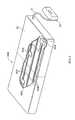
- FIG. 2is a perspective side view of the person support apparatus of the person monitoring system of FIG. 1 according to one illustrative embodiment
- FIG. 3is a perspective side view of a person support surface that is supported on the person support apparatus of FIG. 2 according to one illustrative embodiment
- FIG. 4is a perspective side view of the upper frame of the person support apparatus of FIG. 2 according to one illustrative embodiment
- FIG. 5is diagrammatic view of a control system of the person support apparatus of FIG. 2 according to one illustrative embodiment including a controller and a plurality of sensors;
- FIG. 6is a flow chart illustrating a procedure that can be executed by the controller of the control system of FIG. 5 according to one illustrative embodiment.
- FIG. 7is a diagrammatic view of a control system of the person support apparatus of FIG. 2 according to one illustrative embodiment including a controller and a plurality of sensors.
- One illustrative embodimentincludes a control system coupled to a person support system configured to receive input signals corresponding to at least one of bed status information, person position, electronic medical record information, and physiological information, generate a condition score corresponding to the likelihood of an adverse condition occurring, and alert a caregiver when the condition score exceeds a predetermined threshold.
- the person monitor system 3010includes a signaling and communication system 3012 in communication with a person support apparatus 3014 .
- the person monitor system 3010is configured to provide caregivers with information about a person supported on the person support apparatus 3014 through the signaling and communication system 3012 .
- the signaling and communication system 3012comprises a patient/nurse call system 3012 that, in some embodiments, includes patient stations capable of generating hospital calls and a remote master station which prioritizes and store the calls.
- a patient/nurse call system 3012that, in some embodiments, includes patient stations capable of generating hospital calls and a remote master station which prioritizes and store the calls.
- the signaling and communication system 3012includes a system 3012 for transmitting voice and data in packets over a network with any suitable number of intra-room networks that can couple a number of data devices to an audio station, where the audio station couples the respective intra-room network to a packet based network.
- the signaling and communication system 3012includes a patient/nurse call system, a nurse call/locating badge, an electronic medical record (EMR) database, and one or more computers programmed with work-flow process software.
- EMRelectronic medical record
- One example of such a systemis disclosed in U.S. Patent Publication No. 2008/0094207 published on Apr. 24, 2008 to Collins, Jr. et al., which is incorporated by reference herein in its entirety.
- Another example of such a systemis disclosed in U.S. Patent Publication No. 2007/0210917 published on Sep. 13, 2007 to Collins, Jr. et al., which is incorporated by reference herein in its entirety.
- Yet another example of such a systemis disclosed in U.S. Pat. No. 7,319,386 published on Jan.
- the workflow process softwarecan be the NaviCare® software available from Hill-Rom Company, Inc. It should also be appreciated that the workflow process software can be the system disclosed in U.S. Pat. No. 7,443,303 issued on Oct. 28, 2008 to Spear et al., which is incorporated by reference herein in its entirety. It should further be appreciated that the badge can be of the type available as part of the ComLinxTM system from Hill-Rom Company, Inc. It should also be appreciated that the badge can also be of the type available from Vocera Communications, Inc.
- the remote signaling and communication system 3012is configured to organize, store, maintain and facilitate retrieval of bed status information, along with the various non-bed calls placed in a hospital wing or ward, and remotely identify and monitor the status and location of the person support apparatus, patients, and caregivers.
- a hospital wing or wardOne example of such a system is disclosed in U.S. Pat. No. 7,242,308 issued on Jul. 10, 2007 to Ulrich et al., which is incorporated by reference herein in its entirety.
- the remote status and location monitoringcan be the system disclosed in U.S. Pat. No. 7,242,306 issued on Jul. 10, 2007 to Wildman et al., which is incorporated by reference herein in its entirety.
- the remote status and location monitoringcan be the system disclosed in U.S. Patent Publication No. 2007/0247316 published on Oct. 25, 2007 to Wildman et al., which is incorporated by reference herein in its entirety.
- the person support apparatus 3014according to one illustrative embodiment of the current disclosure is shown in FIG. 2 .
- the person support apparatus 3014includes a head section H 1 , where the head and a portion of the torso of a person are to be positioned, and a foot section F 1 , where the feet of a person are to be positioned.
- the person support apparatus 3014includes a lower frame 3016 or base 3016 , an upper frame 3018 , a plurality of supports 3020 , and a control system 3022 . It should be appreciated that the person support apparatus 3014 can include only one support 3016 .
- the lower frame 3016includes at least one lower frame section supported by casters 3024 .
- the supports 3020are lift mechanisms 3020 that define a vertical axis Z 1 which extends through the lower frame 3016 and the upper frame 3018 and are configured to move the upper frame 3018 with respect to the lower frame 3016 . It should be appreciated that the supports 3020 can be at least one fixed column (not shown), if desired. It should also be appreciated that, in some embodiments, the supports 3020 move the upper frame 3018 to a Trendelenburg/reverse Trendelenburg position and/or rotate the upper frame 3014 from side to side with respect to the lower frame 3012 .
- the person support apparatus 3014supports a person support surface 3026 on the upper frame 3018 as shown in FIGS. 2 and 3 .
- the person support surface 3026is configured to support a person (not shown) in multiple articulated positions.
- the person support surface 3026includes a back portion B 1 and a main portion M 1 .
- the person support surface 3026includes an outer cover or ticking C 1 that covers one or more support sections and/or layers having foam and/or fluid bladders 3028 .
- the person support surface 3026delivers therapy to the person, such as, for example, through sequential inflation/deflation of the fluid bladders 3028 , rapid changes in pressure of the fluid in the fluid bladders 3028 , passing fluid through the person support surface 3026 , and/or various other techniques.
- one or more portions of the surface 3026provide alternating pressure therapy, continuous lateral rotation therapy, low air loss therapy, boost assistance, percussion/vibration therapy, and/or other therapies.
- the person support surface 3026includes a coverlet (not shown) that overlies another person support surface 3026 and is configured to deliver therapy to a person supported thereon.
- the person support surface 3026receives fluid from a fluid supply FS connected to the person support surface 3026 by a connecting tube T 1 .
- the fluid supply FSis a gas blower and is configured to vary at least one of a rate and a temperature of fluid supplied to the person support surface 3026 .
- the upper frame 3018defines a longitudinal axis X 1 that extends at least the length of the person support apparatus 3014 through the head end H 1 and the foot end F 1 along the lateral center of the upper frame 3018 , and a lateral axis Y 1 that is perpendicular to the longitudinal axis X 1 and extends at least the width of the person support apparatus 3014 through the longitudinal center of the upper frame 3018 as shown in FIGS. 2 and 4 .
- the upper frame 3018includes a deck 3030 , an intermediate frame 3032 , and an upper frame base 3034 that couples with the supports 3020 and supports the deck 3030 and the intermediate frame 3032 .
- the upper frame 3018includes a footboard FB, a head board HB, and/or siderails SR in some embodiments.
- the deck 3030is comprised of multiple sections, such as, a head deck section HD, a seat deck section SD, and a foot deck section FD, that are pivotably coupled to one another and/or the intermediate frame 3032 and articulate about the lateral axis Y 1 .
- the control system 3022is configured to control various functions of the person support apparatus 3014 and/or communicate with the signaling and communication system 3012 as shown in FIG. 5 . It should be appreciated that the control system 3022 can be configured to be controlled through the signaling and communication system 3012 , if desired. In one illustrative embodiment, the control system 3022 is configured to articulate the deck 3030 with respect to the intermediate frame 3032 . In some embodiments, the control system 3022 is configured to administer therapy to a person supported on the person support apparatus 3014 . According to some embodiments, the control system 3022 is configured to alert caregivers when a person is exiting the person support apparatus 3014 .
- the control system 3022includes a plurality of sensors 3036 , control modules 3038 , and a display 3040 as shown in FIG. 5 .
- the sensors 3036 and/or the control modules 3038are coupled to the upper frame 3018 in some embodiments. It should be appreciated that the sensors 3036 and/or the control modules 3038 can be coupled to the lower frame 3016 , supports 3020 , and/or incorporated within or coupled to the person support surface 3020 in other embodiments, if desired.
- the sensors 3036 , control modules 3038 , and the display 3040are directly connected to one another.
- the sensors 3036 , control modules 3038 , and the display 3040are operatively connected to one another through a network 3042 .
- the network 3042facilitates communication between the various modules 3038 , sensors 3036 , displays 3040 , and/or other equipment operatively connected to the network 3042 .
- the network 3042comprises a CAN network on a person support apparatus 3014 .
- the network 3042is part of the signaling and communication system 3012 .
- the network 3042comprises a Serial Peripheral Interface (SPI) network.
- SPISerial Peripheral Interface
- the network 3042can be other types of networks or communication protocols that can facilitate communication between two or more devices.
- the module 3038can be configured to connect to the network 3042 wirelessly, if desired.
- control module 3038negotiates with the network 3042 to be a network node.
- control modules 3038can be located at or on any node on the network 3042 and/or distributed across multiple nodes on the network 3042 .
- the sensors 3036are operatively connected to the control modules 3038 and include sensors that contact the person (contact sensors 3044 ) and/or sensors that do not contact the person (contact-less sensors 3046 ) as shown in FIG. 5 .
- the contact sensors 3044contact a person's tissue to measure the desired parameter.
- the contact-less sensors 3046are integrated into the person support surface 3026 . It should be appreciated that the contact-less sensors 3046 can be integrated into the portion of the ticking C 1 contacting the person, if desired.
- the contact-less sensors 3046are coupled to at least one of the upper frame 3018 , the supports 3020 , and/or the lower frame 3016 . It should be appreciated that the contact-less sensors 3046 can be coupled to the casters 3024 and/or engaged by the casters 3024 , if desired.
- the sensors 3036are configured to sense a variety of parameters, including, but not limited to, for example, a person's physiological information, a position of a person on the person support apparatus 3014 and/or person support surface 3026 , a pressure of the fluid inside the bladders 3028 in the person support surface 3026 , or other various parameters.
- the contact sensors 3044include blood pressure sensors 3048 that are configured to sense the person's blood pressure; oxygen saturation level (SpO2) sensors 3050 that are configured to sense the amount of hemoglobin binding sites in the person's bloodstream occupied by oxygen; temperature sensors 3052 that are configured to sense the person's body temperature; heart rate sensors 3054 that are configured to sense the rate at which a person's heart contracts; and respiration rate sensors 3056 that are configured to sense the person's breathing rate as shown in FIG. 5 .
- the SpO2 sensors 3050comprise a pulse oximeter device in some embodiments.
- the contact sensors 3044are configured to measure other physiological and biochemical parameters in other embodiments.
- the contact-less sensors 3046include one or more of the following: force sensors 3058 configured to sense the force profile and/or distribution of a person supported on a person support apparatus 3014 ; pressure sensors 3060 configured to measure the pressure in or among the bladders 3028 ; temperature sensors 3062 configured to sense the person's body temperature; heart rate sensors 3064 configured to sense the rate at which the person's heart contracts; respiration rate sensors 3066 configured to sense the person's breathing rate; and other sensors configured to sense information corresponding to the status of the person-support apparatus 3014 , such as, for example, the angle of the head deck section HD with respect to the longitudinal axis X 1 as shown in FIG. 5 .
- the force sensors 3058are load cells 3058 that couple the intermediate frame 3032 to the upper frame base 3034 proximate the corners of the upper frame 3018 and are configured to measure the weight of a person on the person support apparatus 3014 .
- the force sensors 3058comprise piezoelectric sensors and/or elongated sensor strips or arrays 3058 in some embodiments.
- the pressure sensors 3060are coupled between the bladders 3028 such that they allow communication between adjacent bladders 3028 .
- pressure sensors 3060are situated within the bladders 3028 and measure the pressure within the bladder 3028 .
- the heart rate sensors 3064 and respiration rate sensors 3066are integrated into the surface 3026 .
- the heart rate sensors 3064 and respiration rate sensors 3066are force sensors 3058 and/or pressure sensors 3060 . It will be appreciated that the sensors 3036 are configured to sense various other physiological characteristics.
- the heart rate sensors 3064 and respiration rate sensors 3066are pressure-strip sensors disposed on the fluid bladders 3028 along an axis parallel to the lateral axis Y 1 and/or along an axis parallel to the longitudinal axis X 1 .
- the control modules 3038can each be configured to perform different operations, if desired. According to this disclosure, a single control module 3038 can be configured to perform the multiple different operations if desired. Optionally, a single control module 3038 can be configured to perform operations independently or in conjunction with at least one other control module 3038 . In one contemplated embodiment, one control module 3038 , such as, a person position monitor module (not shown) (PPM), is configured to detect the position of a person on the person support apparatus 3014 . Alternatively or additionally, a second control module 3038 , such as a therapy control module (not shown), is configured to sense and/or modify the pressure within the fluid bladders 3028 .
- PPMperson position monitor module
- a second control module 3038such as a therapy control module (not shown) is configured to sense and/or modify the pressure within the fluid bladders 3028 .
- a third control module 3038such as a physiological parameter monitor (not shown), is configured to detect a person's physiological information.
- a fourth control module 3038such as a wake up detector (not shown), is configured to detect when a person is regaining consciousness.
- the control modules 3038are implemented using software or hardware. In some embodiments, the control modules 3038 are implemented in software and are configured to perform one or more operations. In some embodiments, for example, the modules 3038 are configured to communicate via a memory mailbox where information from one module is sent to the memory address of a recipient module. In other embodiments, the software modules are configured to push information in a memory location, such as, a stack, that the control modules 3038 monitor or periodically check for information that the software modules subscribe to.
- control module 3038is implemented using hardware.
- the control module 3038includes a controller 3074 or processor 3074 and memory 3076 as shown in FIG. 5 .
- the controller 3074is provided as a single component or a collection of operatively coupled components; and can be comprised of digital circuitry, analog circuitry, or a hybrid combination of both of these types.
- controller 3074has one or more components remotely located relative to the others.
- the controller 3074can include multiple processing units arranged to operate independently, in a pipeline processing arrangement, in a parallel processing arrangement, and/or such different arrangement as would occur to those skilled in the art.
- processor 3074is a programmable microprocessing device of a solid-state, integrated circuit type that includes one or more processing units and memory.
- the controller 3074can include one or more signal conditioners, modulators, demodulators, Arithmetic Logic Units (ALUs), Central Processing Units (CPUs), limiters, oscillators, control clocks, amplifiers, signal conditioners, filters, format converters, communication ports, clamps, delay devices, memory devices, and/or different circuitry or functional components as would occur to those skilled in the art to perform the desired communications.
- the controller 3074includes a computer network interface to communicate among various system components and/or components not included in the depicted system, as desired.
- the listed examplesare not intended to be an exhaustive list of structures that are within the scope of controller 3074 , but are instead only a non-exhaustive list of such structures which can have substantial differences in the manner in which they are implemented and/or operate.
- the controller 3074is configured to receive input signals corresponding to signals from the sensors 3036 and/or output signals from other modules 3038 via the network 3042 .
- the informationis stored in the memory 3076 , which is operatively coupled to the controller 3074 as shown in FIG. 5 . It should be appreciated that the memory 3076 is integrated into the controller in some embodiments.
- the controller 3074is configured to execute operating logic 3078 that defines various control, management, and/or regulation functions.
- This operating logic 3078can be in the form of software, firmware, and/or dedicated hardware, such as, a series of programmed instructions, code, electronic files, or commands using general purpose or special purpose programming languages or programs that are executed on one or more general purpose or special purpose computers, processors, other control circuitry, or networks; a hardwired state machine; and/or a different form as would occur to those skilled in the art.
- the controller 3074includes operating logic 3078 in the form of procedure 3080 , for example, as shown in the flowchart of FIG. 6 .
- Procedure 3080includes operations/conditionals shown at blocks 3082 , 3084 , 3086 , and 3088 .
- Procedure 3080is used to generate a condition score corresponding to the condition of a person, which is compared to a threshold in order to predict the onset of an adverse condition.
- the thresholdsare established in accordance with hospital specific standard protocols and/or are generic thresholds that can be modified as desired.
- the preset thresholdsthat are set by standard hospital specific protocols, which are automatically selected based on information present in a person's electronic medical record (EMR), in patient profiles, and/or based on the condition score generated by the procedure 3080 .
- the thresholdsare set by a caregiver through an interface (not shown) on the person-support apparatus 3014 by manually selecting the protocols or modifying the generic thresholds.
- the thresholdsare automatically modified based on information in the person's electronic medical record (EMR).
- EMRelectronic medical record
- the thresholdscan be person specific and can be incorporated into the person's EMR.
- the thresholdscan be incorporated into a patient profile that can be used for multiple people with similar characteristics.
- the thresholdsare modified by a caregiver through the signaling and communication system 3012 .
- Illustrative procedure 3080begins with operation 3082 where, in one illustrative embodiment, the sensors 3036 generate data signals corresponding to one or more of heart rate (HR), respiration rate (RR), temperature (TEMP), blood pressure (BP) or pulse oximetry (SpO2) and post them to the network.
- HRheart rate
- RRrespiration rate
- BPblood pressure
- SpO2pulse oximetry
- the predetermined thresholdis modified by the status of a care facility.
- the predetermined thresholdis modified by one or more of the staffing level of the facility, the time of day, the day of the week, whether the day is a holiday, what the acuity of the person is, what the acuity of the other people in the hospital is, the location of the caregiver with respect to the person, where the caregiver is in their rounds with respect to the person, the amount of people in the facility, the size of the facility, the work-flow status of the facility, the amount of procedures taking place and/or the time they begin and/or the duration of the procedure, or other information regarding the facility and facility staff.
- Modifying the threshold based on the status of the care facility informationcan help increase the accuracy of the threshold if, for example, staffing levels are lower or if adverse events are more prone to occur while the patient is asleep (i.e., time of day). Also, if a calculated condition score is within a predetermined amount of the predetermined threshold, additional staff could be deployed to an area near the patient, or redeployed to move closer to patient, or the frequency of caregiver visits to patient can be increased to position caregivers in close proximity to the patient. This could help reduce the number of false alerts.
- the predetermined thresholdis modified by the status of the person-support apparatus 3014 .
- the predetermined thresholdis modified by one or more of the height of the upper frame 3018 , the angle at which a section of a deck 3030 is with respect to the upper frame 3018 , the position of the siderail SR, at least one of the Trendelenburg position and the reverse Trendelenburg position, the status of the CPR function, the center of gravity of the person-support apparatus 3014 and/or the person supported thereon, the position of a person on the person-support apparatus 3014 , the status of the alarms on the person-support apparatus 3014 , and/or other information about the person-support apparatus 3014 .
- Modifying the threshold based on the status of the person-support apparatus 3014can help increase the accuracy of the threshold if, for example, a person is classified as a fall risk and the person-support apparatus 3014 is 36 inches above the floor, or less acute if, for example, the person is classified as a fall risk and the person-support apparatus 3014 is 12 inches off the floor. In some embodiments, the person does not need to be classified as a fall risk. Also, the threshold can be made more acute if, for example, the person-support apparatus 3014 is in a Trendelenberg configuration and the person is prone to sliding down (out of a therapeutic position). In some embodiments, the person does not need to be prone to sliding down. This could help reduce the number of false alerts.
- the predetermined thresholdis modified by the person's history.
- the predetermined thresholdis modified by one or more of a person's preferences, a person's tendencies, a person's electronic medical records (EMR), a pressure ulcer risk assessment of a person, a medical history of a person, an allergy of a person, a medical condition of a person, a diagnosis of a person, a medication chart for a person, a caregiver assignment history for a person, a habit of a person, and other information about the person.
- EMRelectronic medical records
- Modifying the threshold based on the status of the person's historycan help increase the accuracy of the threshold if, for example, the person is classified as a fall risk or is more apt to fall out of bed, or is prone to developing pressure ulcers or might be at an elevated risk for developing pressure ulcers. This could help reduce the number of false alerts.
- the predetermined thresholdis modified by the status of the support surface 3026
- the predetermined thresholdis modified by one or more of the fluid pressure in the fluid bladder 3028 , the status of a surface therapy, the status of a low-air loss therapy, the status of a percussion vibration therapy, the status of a lateral rotation therapy, the status of an alternating pressure therapy, the status of a zone of the person-support surface 3026 , the status of a person-support surface function, the status of a person-support surface length extension function, the status of a person-support surface length reduction function, the status of a person-support surface width extension function, the status of a person-support surface width reduction function, the status of a turn assist function, the position of a person on the person-support surface 3026 , the morphology of a person on the person-support surface 3026 , or other information about the person-support surface 3026 . Modifying the threshold based on the status of the support surface 3026 can help reduce the amount of false calls due
- the predetermined thresholdis modified by the input from the interface, i.e., user interface. Modifying the threshold based on inputs from the user interface can help improved functionality of the system by permitting the user to optimize based upon a condition that has not been predetermined.
- Procedure 3080begins with operation 3082 where the sensors 3036 post electronic data signals corresponding to at least one of an event and an amount on the network 3042 .
- the sensors 3036post electronic data signals to a memory mailbox or register (not shown) where the modules 3038 are implemented in software.
- sensors 3036post data signals substantially continuously and, in other embodiments, sensors 3036 post data signals at predetermined intervals.
- the data signals from sensors 3036are representative of heart rate, respiration rate, temperature, blood pressure and/or SpO2 as indicated at block 3082 of FIG. 6 .
- Data signals corresponding to features of the person support apparatus 3014are also posted to the network such as, for example, signals from force sensors 3044 of a patient position and/or movement monitoring system of apparatus 3014 and are used in a similar manner as signals from sensors 3036 in procedure 3080 .
- the controller 3074examines each of the data signals posted by the sensors 3036 on the network 3042 and determines if the associated module 3038 subscribes to the data. If the module 3038 does not subscribe to the data, then the algorithm returns to block 3082 and awaits more incoming data.
- the algorithmproceeds to the operation of block 3086 and the data is input into an algorithm that is used to predict an adverse event or condition.
- the data signalscan be used to select one or more standard hospital specific protocols, which, in some instances, have predetermined thresholds associated therewith.
- the data signalscan be input into an algorithm that is used to select the hospital specific protocols and/or to set the predetermined thresholds associated with the protocols.
- the controller 3074executes the algorithm to generate a condition score corresponding to the condition of the person and/or to generate a graphic representative of the condition of the person.
- the algorithmreceives inputs from the contact-less sensors 3046 corresponding to the heart rate, respiration rate, and temperature of a person, and inputs from the contact sensors 3044 corresponding to the blood pressure and SpO2 of a person. It should be understood that all of the inputs can be from the contact sensors 3044 in other embodiments.
- the controller 3074processes the data inputs in accordance with the algorithm to calculate the condition score and/or generate the graphic.
- the algorithmcombines the inputs into a data point, which is used to calculate a condition score constituting a one-dimensional visualization space based on the distance of the data point in a multi-dimensional measurement space, whose coordinates are defined by values of the inputs, from a normal point.
- the inputsare weighted such that an input deemed to be more important than another has more influence on the resulting data point and/or condition score.
- the weight assigned to the inputsare modified based on at least one of a status of a care facility, a status of the person-support apparatus 3014 , a status of the person-support surface 3026 , a history of a person supported on the person-support surface 3026 , and a user input as previously described above.
- the algorithmmaps the inputs from an n-dimensional measurement space to an m-dimensional visualization space using a dimensionality reduction mapping technique, and displays the m-dimensional visualization space on the display 3040 .
- a dimensionality reduction mapping techniquemaps the inputs from an n-dimensional measurement space to an m-dimensional visualization space using a dimensionality reduction mapping technique, and displays the m-dimensional visualization space on the display 3040 .
- One condition score in accordance with the teachings of U.S. Pat. No. 7,031,857is know as a Visensia® index that can be produced by the Visensia® system sold by OBS Medical, for example.
- the Visensia® indexcreates a score based on heart rate, respiration rate, blood pressure, temperature, and SpO2 data.
- the Visensia® indexis a condition score that is based on, or a function of, only a person's physiological data.
- some or all of the physiological data used to calculate the Visensia® indexis obtained by one or more sensors included as part of the person support apparatus 3014 . This distinguishes over the known prior art.
- some of the physiological data needed to calculate a condition scoresuch as the Visensia® index, is obtained by equipment and/or sensors that are not included as part of person support apparatus 3014 , such data is transmitted to controller 3074 in accordance with this disclosure for the purpose of calculating the condition score.
- controller 3074For example, data is transmitted to controller 3074 from a person's EMR in some instances as suggested diagrammatically in FIG. 5 .
- person support apparatus 3014is communicatively coupled to physiological monitoring equipment that is co-located with apparatus 3014 to obtain the needed data for calculating a condition score.
- controller 3074automatically initiates the queries to obtain the needed data from the EMR or co-located equipment and/or picks up the needed data from network transmissions.
- controller 3074automatically calculates the condition score without the need for any further actions on the part of caregivers or users.
- the condition scorecomprises a modified early warning score (MEWS).
- MEWSmodified early warning score
- the data needed to calculate the MEWSis obtained from sensors included as part of person support apparatus 3014 , obtained via manual user inputs, obtained from separate monitoring equipment that communicates with controller 3074 of apparatus 3014 , and/or obtained from the person's EMR.
- the MEWSis a known score calculated based on the following table:
- the various integers in the column headingsare added together based on the various readings for the person of the data corresponding to the rows of the table.
- a score of 5 or greaterindicates a likelihood of death.
- those pieces of informationare obtained using sensors 3036 of person support apparatus 3014 and/or using the other manners of obtaining a person's physiological data as discussed above. It is contemplated by this disclosure that the AVPU portion of the MEWS is obtained using information from the person support apparatus 3014 as discussed below.
- the AVPU portion of the MEWSindicates whether a person is alert (A), responsive to voice (V), responsive to pain (P), or unresponsive (U).
- the person support apparatus 3014in some embodiments comprises a hospital bed having a patient position monitoring system including sensors, such as load cells, piezoelectric sensors, and/or force sensitive resistors (FSR's) which sense a patient's position and/or movement.
- the patient movement informationis used by the controller to automatically assign an appropriate integer corresponding to the A portion or the U portion of the AVPU line of the MEWS depending upon the amount of movement of the patient.
- the integer associated with the U portion of the AVPU line of the MEWSis assigned automatically by controller 3074 . If the patient has moved by a threshold amount within a particular time period, then the integer associated with the A portion of the AVPU line of the MEWS is assigned automatically by controller 3074 .
- the controller 3074initiates a voice query to the person in some embodiments. If the person answers the voice query orally or by engaging a designated user input, such as pressing a particular button mentioned in the voice query, then the controller 3074 automatically assigns an appropriate integer corresponding to the V portion of the MEWS.
- the voice queryis a pre-recorded message in some embodiments.
- the voice queryis initiated by controller 3074 if the person has been inactive for the threshold period of time. In other words, in some embodiments, the voice query is initiated only after the conditions for assigning the U portion of the MEWS has been satisfied. Thus, if the person responds properly to the voice query, the AVPU portion of the MEWS is assigned as V rather than U.
- Apparatus 3014therefore, has speakers or similar such sound-producing devices through which the voice query is played and, in some instances, a microphone that picks up the person's oral response.
- Appropriate interactive voice recognition (IVR) softwareis provided in such embodiments.
- apparatus 3014is operated to inflict some amount of discomfort to the patient and then monitors the person's response, such as an oral response or movement.
- apparatus 3014includes an inflatable cuff or sleeve placed on a limb of the person and the controller 3074 controls inflation and deflation of the cuff or sleeve. If the patient movement information indicates sufficient patient movement by the patient in response to inflation of the cuff or sleeve, then the controller automatically assigns the appropriate integer corresponding to the P portion of the AVPU line of the MEWS.
- a microphoneis used to determine if the patient expresses an audible pain or discomfort sound at which point the integer associated with the P portion of the AVPU line of the MEWS is assigned.
- the steps for determining whether to assign the P integerare performed only after the steps for determining whether to assign the U integer and/or the V integer in some embodiments. That is, operating the person apparatus 3014 so as to cause the patient some discomfort is only done as a last resort.
- assigning the AVPU integer in the MEWSit will be appreciated that it is the lowest pertinent integer that is assigned.
- an alert personwould also be responsive to voice for example.
- condition scoresare just a couple of examples of condition scores according to this disclosure.
- teachings of this disclosureare intended to be broadly applicable to all types of condition scores.
- the controller 3074compares the calculated condition score (referred to sometimes in FIG. 6 as an “index value” or simply an “index”) with the predetermined thresholds to determine at least one of the likelihood that an adverse condition will occur, an amount of time before an adverse condition will occur, and/or how close the condition score is to the threshold.
- the calculated condition score(referred to sometimes in FIG. 6 as an “index value” or simply an “index”) with the predetermined thresholds to determine at least one of the likelihood that an adverse condition will occur, an amount of time before an adverse condition will occur, and/or how close the condition score is to the threshold.
- a status update including the condition scoreis communicated to a caregiver through the signaling and communication system 3012 and/or is displayed on the display 3040 as indicated at block 3110 . That is, if the condition score exceeds the threshold, then, in some embodiments, at least one of the condition score and an alert signal are communicated to a caregiver. In other embodiments, the alert condition may correspond to the condition score being less than, rather than greater than, a particular threshold.
- the frequency of the alertscan be adjusted based on one or more of the user input, the acuity level of the person, the status of the care facility, the status of the person-support apparatus 3014 , the status of the person-support surface 3026 , the history of the person, and other information.
- condition score and/or alert signalare communicated to a caregiver through the signaling and communication system 3012 .
- condition score and/or alert signalare displayed on the display 3040 .
- condition score and/or alert signalare communicated to the Visensia® Alert system sold by OBS Medical.
- the condition scoreis communicated to and stored in the person's EMR.
- the display 3040is any suitable display such as a liquid crystal display, touch screen display, plasma screen, light emitting diode display, cathode ray tube display, or other conventional display.
- the display 3040is operable to display multiple parameters thereon along with the condition score in some embodiments.
- the display 3040displays physiological and/or biochemical information sensed by contact sensors 3044 along with the condition score.
- the display 3040it is within the scope of this disclosure for the display 3040 to display physiological and/or biochemical information on the display 3040 along with the condition score.
- the display 3040displays bed status information and/or graphics, for example, a head deck section HD angle or PPM armed indicator, on the display along with the condition score.
- the display 3040displays bed status information and/or graphics along with patient condition graphics, such as, pie charts.
- Other information that is displayable on the display 3040includes force profile information and/or graphics, person position information and/or graphics, weight, and other physiological information.
- the sensors 3036are operatively coupled to the control modules 3038 and are configured to sense various parameters, including, but not limited to, for example, a person's physiological information, a position of a person on the person support apparatus 3014 and/or person support surface 3026 , a pressure of the fluid inside the bladders 3028 in the person support surface 3026 , or other various parameters.
- the sensors 3036can be sensors configured to contact the tissue of a person and/or sensors configured to not contact the tissue of a person.
- the sensors 3036are force sensors 3044 coupled to the upper frame 3018 and are configured to measure force on the upper frame 3018 as shown in FIGS. 4 and 7 .
- the sensors 3036are force sensors 3044 that measure force on the upper frame 3018 and are positioned between the intermediate frame 3032 and the upper frame base 3034 so as to couple the intermediate frame 3032 and deck 3030 to the upper frame base 3034 .
- the sensors 3036are force sensors 3044 integrated into the person support surface 3026 and configured to measure changes in force on the person support surface 3026 as shown in FIG. 4 .
- the force sensors 3044are coupled to the supports 3020 and/or the lower frame 3016 .
- Sensors 3044 integrated into the casters 3024 and/or engaged by the casters 3024are also within the scope of this disclosure.
- the force sensors 3044are load cells that are coupled proximate the corners of the intermediate frame 3032 .
- the sensors 3044are piezoelectric sensors and/or elongated sensor strips or arrays 3038 . It will be appreciated that the force sensors 3044 comprising other force sensor types can be provided and positioned in other locations on the upper frame 3018 and/or within the person support surface 3026 .
- the sensors 3036are pressure sensors 3046 integrated into the person support surface 3026 and configured to measure the pressure in or among the fluid bladders 3028 in the person support surface 3026 as shown diagrammatically in FIG. 7 .
- the pressure sensors 3046are coupled between the bladders 3028 in some embodiments such that they can allow communication between adjacent bladders 3028 . It should be appreciated that the pressure sensors can be situated within the bladders 3028 and/or otherwise positioned to measure the pressure within the bladder 3028 .
- Pressure sensors 3046 coupled to bladders 3028 via pneumatic tubes, hoses, or other types of conduitsare contemplated by this disclosure as well.
- the sensors 3036are physiological sensors 3048 integrated into the person support surface 3026 and configured to measure various physiological parameters of a person supported on the person support surface 3026 as suggested in FIG. 7 .
- the physiological sensors 3048can be coupled to the upper frame 3018 , the supports 3020 , and/or the lower frame 3016 in lieu of being coupled to the mattress 3046 .
- the force sensor 3044 and/or pressure sensor 3046are configured to sense physiological parameters in some embodiments.
- one or more of the physiological sensors 3048are used to sense the heart rate and/or respiration rate of a person supported on the person support surface 3026 in some embodiments.
- one or more of the physiological sensors 3048are configured to sense the temperature of the person.
- the physiological sensors 3048are configured to sense the weight of the person on the person support surface 3026 .
- the physiological sensors 3048are pressure-strip sensors disposed on the fluid bladders 3028 along an axis parallel to the lateral axis Y 1 and/or along an axis parallel with the longitudinal axis X 1 .
- one or more of the sensors 3036produces an analog data signal and is connected directly to the controller 3074 .
- one or more of the sensors 3036produce a digital data signal, e.g., a serial digital data signal, and are connected to the network 3042 , e.g., SPI network, to communicate with the controller 3074 .
- the data signalscan be stored in the memory 3076 , which is operatively coupled with the controller 3074 .
- the memory 3076is integrated into the controller 3074 in some embodiments.
- the controller 3074executes operating logic that defines various control, management, and/or regulation functions.
- This operating logiccan be in the form of software, firmware, and/or dedicated hardware, such as, a series of programmed instructions, code, electronic files, or commands using general purpose or special purpose programming languages or programs that can be executed on one or more general purpose or special purpose computers, processors, other control circuitry, or networks; a hardwired state machine; and/or a different form as would occur to those skilled in the art.
Landscapes
- Health & Medical Sciences (AREA)
- Life Sciences & Earth Sciences (AREA)
- Engineering & Computer Science (AREA)
- Public Health (AREA)
- General Health & Medical Sciences (AREA)
- Medical Informatics (AREA)
- Biomedical Technology (AREA)
- Animal Behavior & Ethology (AREA)
- Veterinary Medicine (AREA)
- Pathology (AREA)
- Heart & Thoracic Surgery (AREA)
- Molecular Biology (AREA)
- Surgery (AREA)
- Biophysics (AREA)
- Physics & Mathematics (AREA)
- Physiology (AREA)
- Cardiology (AREA)
- Primary Health Care (AREA)
- Epidemiology (AREA)
- Artificial Intelligence (AREA)
- Computer Vision & Pattern Recognition (AREA)
- Signal Processing (AREA)
- Psychiatry (AREA)
- Oral & Maxillofacial Surgery (AREA)
- Pulmonology (AREA)
- Immunology (AREA)
- Vascular Medicine (AREA)
- Dentistry (AREA)
- Nursing (AREA)
- Data Mining & Analysis (AREA)
- Databases & Information Systems (AREA)
- Business, Economics & Management (AREA)
- General Business, Economics & Management (AREA)
- Measuring And Recording Apparatus For Diagnosis (AREA)
- Invalid Beds And Related Equipment (AREA)
Abstract
Description
| Score | ||
| 3 | 2 | 1 | 0 | 1 | 2 | 3 | ||
| Systolic | <70 | 71-80 | 81-100 | 101-199 | — | >200 | — |
| BP | |||||||
| Heart rate | — | <40 | 41-50 | 51-100 | 101-110 | 111-129 | >130 |
| (BPM) | |||||||
| Respira- | — | <9 | — | 9-14 | 15-20 | 21-29 | >30 |
| tory rate | |||||||
| (RPM) | |||||||
| Temper- | — | <35 | — | 35.0-38.4 | — | >38.5 | — |
| ature | |||||||
| (° C.) | |||||||
| AVPU | — | — | — | A | V | P | U |
Claims (20)
Priority Applications (2)
| Application Number | Priority Date | Filing Date | Title |
|---|---|---|---|
| US13/153,592US8844073B2 (en) | 2010-06-07 | 2011-06-06 | Apparatus for supporting and monitoring a person |
| US14/493,475US20150032384A1 (en) | 2010-06-07 | 2014-09-23 | Apparatus for supporting and monitoring a person |
Applications Claiming Priority (2)
| Application Number | Priority Date | Filing Date | Title |
|---|---|---|---|
| US35203310P | 2010-06-07 | 2010-06-07 | |
| US13/153,592US8844073B2 (en) | 2010-06-07 | 2011-06-06 | Apparatus for supporting and monitoring a person |
Related Child Applications (1)
| Application Number | Title | Priority Date | Filing Date |
|---|---|---|---|
| US14/493,475DivisionUS20150032384A1 (en) | 2010-06-07 | 2014-09-23 | Apparatus for supporting and monitoring a person |
Publications (2)
| Publication Number | Publication Date |
|---|---|
| US20110301440A1 US20110301440A1 (en) | 2011-12-08 |
| US8844073B2true US8844073B2 (en) | 2014-09-30 |
Family
ID=44546414
Family Applications (2)
| Application Number | Title | Priority Date | Filing Date |
|---|---|---|---|
| US13/153,592Active2032-12-10US8844073B2 (en) | 2010-06-07 | 2011-06-06 | Apparatus for supporting and monitoring a person |
| US14/493,475AbandonedUS20150032384A1 (en) | 2010-06-07 | 2014-09-23 | Apparatus for supporting and monitoring a person |
Family Applications After (1)
| Application Number | Title | Priority Date | Filing Date |
|---|---|---|---|
| US14/493,475AbandonedUS20150032384A1 (en) | 2010-06-07 | 2014-09-23 | Apparatus for supporting and monitoring a person |
Country Status (2)
| Country | Link |
|---|---|
| US (2) | US8844073B2 (en) |
| EP (2) | EP3056178B1 (en) |
Cited By (13)
| Publication number | Priority date | Publication date | Assignee | Title |
|---|---|---|---|---|
| US20130249695A1 (en)* | 2012-03-23 | 2013-09-26 | Elly Hann | Systems and methods for assessing risks of pressure ulcers |
| US20140331412A1 (en)* | 2008-03-15 | 2014-11-13 | Stryker Corporation | Force sensing sheet |
| US20150005675A1 (en)* | 2009-09-18 | 2015-01-01 | Hill- Rom Services, Inc. | Apparatus for Supporting and Monitoring a Person |
| US20170135494A1 (en)* | 2015-11-17 | 2017-05-18 | Dreamwell, Ltd. | Mattress with flexible pressure sensor |
| US10357185B2 (en)* | 2014-10-17 | 2019-07-23 | Stryker Corporation | Person support apparatuses with motion monitoring |
| US20190350780A1 (en)* | 2018-05-21 | 2019-11-21 | Hill-Rom Services, Inc. | Patient support apparatus adaptable to multiple modes of transport |
| US10634549B2 (en) | 2016-02-11 | 2020-04-28 | Hill-Rom Services, Inc. | Hospital bed scale calibration methods and patient position monitoring methods |
| US10745039B1 (en)* | 2019-08-19 | 2020-08-18 | Sbot Technologies, Inc. | Accurate weight measurement system and method operable with a movable device |
| US10786408B2 (en) | 2014-10-17 | 2020-09-29 | Stryker Corporation | Person support apparatuses with exit detection systems |
| US11172892B2 (en) | 2017-01-04 | 2021-11-16 | Hill-Rom Services, Inc. | Patient support apparatus having vital signs monitoring and alerting |
| US11419554B2 (en)* | 2015-12-30 | 2022-08-23 | Dewertokin Technology Group Co., Ltd | Sleeping or reclining furniture and electric motor furniture drive for such furniture |
| US12036161B2 (en) | 2019-08-16 | 2024-07-16 | Stryker Corporation | Patient support with deck width monitoring and control |
| US12408845B2 (en) | 2019-08-20 | 2025-09-09 | Stryker Corporation | Person support apparatus with adjustable exit detection zones |
Families Citing this family (60)
| Publication number | Priority date | Publication date | Assignee | Title |
|---|---|---|---|---|
| US20130127620A1 (en) | 2011-06-20 | 2013-05-23 | Cerner Innovation, Inc. | Management of patient fall risk |
| US9741227B1 (en) | 2011-07-12 | 2017-08-22 | Cerner Innovation, Inc. | Method and process for determining whether an individual suffers a fall requiring assistance |
| US10546481B2 (en) | 2011-07-12 | 2020-01-28 | Cerner Innovation, Inc. | Method for determining whether an individual leaves a prescribed virtual perimeter |
| US9320662B2 (en)* | 2011-10-18 | 2016-04-26 | Stryker Corporation | Patient support apparatus with in-room device communication |
| US9295390B2 (en)* | 2012-03-02 | 2016-03-29 | Hill-Rom Services, Inc. | Facial recognition based monitoring systems and methods |
| US9213956B2 (en)* | 2012-03-14 | 2015-12-15 | Hill-Rom Services, Inc. | Algorithm for predicting and mitigating adverse events |
| ES1076877Y (en)* | 2012-03-26 | 2012-08-07 | Servicio Andaluz De Salud | NEONATE MONITORING DEVICE |
| EP2667313B1 (en) | 2012-05-22 | 2021-08-04 | Hill-Rom Services, Inc. | Adverse condition detection, assessment, and response system |
| WO2013177338A2 (en)* | 2012-05-22 | 2013-11-28 | Hill-Rom Services, Inc. | Adverse event mitigation systems, methods and devices |
| WO2014149392A1 (en)* | 2013-03-15 | 2014-09-25 | Hill-Rom Services, Inc. | Adverse event mitigation systems, methods and devices |
| US9704377B2 (en) | 2012-06-13 | 2017-07-11 | Wearsafe Labs, Llc | Systems and methods for managing an emergency situation |
| US9349366B2 (en)* | 2012-06-13 | 2016-05-24 | Wearsafe Labs Llc | Systems and methods for managing an emergency situation |
| US10420690B2 (en)* | 2012-07-12 | 2019-09-24 | Liko Research & Development Ab | Monitoring systems devices and methods for patient lifts |
| US9468307B2 (en) | 2012-09-05 | 2016-10-18 | Stryker Corporation | Inflatable mattress and control methods |
| WO2014085302A1 (en)* | 2012-11-27 | 2014-06-05 | Faurecia Automotive Seating, Llc | Vehicle seat with integrated sensors |
| WO2015044859A1 (en)* | 2013-09-27 | 2015-04-02 | Koninklijke Philips N.V. | A methodology for hospitalized patient monitoring and icu risk prediction with a physiologic based early warning system |
| US10096223B1 (en) | 2013-12-18 | 2018-10-09 | Cerner Innovication, Inc. | Method and process for determining whether an individual suffers a fall requiring assistance |
| US10078956B1 (en) | 2014-01-17 | 2018-09-18 | Cerner Innovation, Inc. | Method and system for determining whether an individual takes appropriate measures to prevent the spread of healthcare-associated infections |
| US9729833B1 (en) | 2014-01-17 | 2017-08-08 | Cerner Innovation, Inc. | Method and system for determining whether an individual takes appropriate measures to prevent the spread of healthcare-associated infections along with centralized monitoring |
| US10225522B1 (en) | 2014-01-17 | 2019-03-05 | Cerner Innovation, Inc. | Method and system for determining whether an individual takes appropriate measures to prevent the spread of healthcare-associated infections |
| US20150297433A1 (en)* | 2014-04-18 | 2015-10-22 | Jeanette Owens | Medical procedure table with integral ports and wires for electrocardiography |
| US20150342538A1 (en)* | 2014-06-03 | 2015-12-03 | Welch Allyn, Inc. | Custom early warning scoring for medical device |
| US10292881B2 (en) | 2014-10-31 | 2019-05-21 | Hill-Rom Services, Inc. | Dynamic apnea therapy surface |
| CN106999108A (en)* | 2014-12-10 | 2017-08-01 | 皇家飞利浦有限公司 | System and method for falling detection |
| US10090068B2 (en) | 2014-12-23 | 2018-10-02 | Cerner Innovation, Inc. | Method and system for determining whether a monitored individual's hand(s) have entered a virtual safety zone |
| US10524722B2 (en) | 2014-12-26 | 2020-01-07 | Cerner Innovation, Inc. | Method and system for determining whether a caregiver takes appropriate measures to prevent patient bedsores |
| US10091463B1 (en) | 2015-02-16 | 2018-10-02 | Cerner Innovation, Inc. | Method for determining whether an individual enters a prescribed virtual zone using 3D blob detection |
| US10342478B2 (en) | 2015-05-07 | 2019-07-09 | Cerner Innovation, Inc. | Method and system for determining whether a caretaker takes appropriate measures to prevent patient bedsores |
| US20160338591A1 (en)* | 2015-05-21 | 2016-11-24 | Hill-Rom Services, Inc. | Systems and methods for mitigating tissue breakdown |
| US9892611B1 (en) | 2015-06-01 | 2018-02-13 | Cerner Innovation, Inc. | Method for determining whether an individual enters a prescribed virtual zone using skeletal tracking and 3D blob detection |
| EP3111906B1 (en) | 2015-07-01 | 2023-05-10 | Liko Research & Development AB | Person lifting devices and methods for operating person lifting devices |
| EP3111907B1 (en) | 2015-07-01 | 2021-03-10 | Liko Research & Development AB | Person lifting devices with accessory detection features and methods for operating the same |
| US10376434B2 (en) | 2015-07-31 | 2019-08-13 | Liko Research & Developmetn AB | Person lift devices and scale assemblies for person lift devices including accessory tracking features |
| US10314758B2 (en) | 2015-07-31 | 2019-06-11 | Allen Medical Systems, Inc. | Person support apparatus with tracking features |
| JP6613828B2 (en)* | 2015-11-09 | 2019-12-04 | 富士通株式会社 | Image processing program, image processing apparatus, and image processing method |
| US10614288B2 (en) | 2015-12-31 | 2020-04-07 | Cerner Innovation, Inc. | Methods and systems for detecting stroke symptoms |
| US10489661B1 (en) | 2016-03-08 | 2019-11-26 | Ocuvera LLC | Medical environment monitoring system |
| US10600204B1 (en) | 2016-12-28 | 2020-03-24 | Ocuvera | Medical environment bedsore detection and prevention system |
| US10147184B2 (en) | 2016-12-30 | 2018-12-04 | Cerner Innovation, Inc. | Seizure detection |
| US10945679B2 (en)* | 2017-01-31 | 2021-03-16 | Welch Allyn, Inc. | Modular monitoring smart bed |
| US10258295B2 (en) | 2017-05-09 | 2019-04-16 | LifePod Solutions, Inc. | Voice controlled assistance for monitoring adverse events of a user and/or coordinating emergency actions such as caregiver communication |
| US10905611B2 (en)* | 2017-12-22 | 2021-02-02 | Stryker Corporation | Techniques for notifying persons within a vicinity of a patient support apparatus of a remote control function |
| US10643446B2 (en) | 2017-12-28 | 2020-05-05 | Cerner Innovation, Inc. | Utilizing artificial intelligence to detect objects or patient safety events in a patient room |
| US10482321B2 (en) | 2017-12-29 | 2019-11-19 | Cerner Innovation, Inc. | Methods and systems for identifying the crossing of a virtual barrier |
| US11908581B2 (en) | 2018-04-10 | 2024-02-20 | Hill-Rom Services, Inc. | Patient risk assessment based on data from multiple sources in a healthcare facility |
| US11504071B2 (en) | 2018-04-10 | 2022-11-22 | Hill-Rom Services, Inc. | Patient risk assessment based on data from multiple sources in a healthcare facility |
| US11903712B2 (en)* | 2018-06-08 | 2024-02-20 | International Business Machines Corporation | Physiological stress of a user of a virtual reality environment |
| WO2020030455A1 (en)* | 2018-08-09 | 2020-02-13 | Koninklijke Philips N.V. | Method and system for cardiovascular risk assessment for patients |
| US11219381B2 (en)* | 2018-10-16 | 2022-01-11 | Xue Chen | Nursing bed based on heart rate monitoring and voice recognition |
| US10922936B2 (en) | 2018-11-06 | 2021-02-16 | Cerner Innovation, Inc. | Methods and systems for detecting prohibited objects |
| EP3653110B1 (en)* | 2018-11-16 | 2025-09-03 | Hill-Rom Services, Inc. | System for determining a pressure injury score and altering a treatment plan based on the pressure injury score |
| KR102588081B1 (en)* | 2019-03-05 | 2023-10-11 | 가부시키가이샤 후지 | commercial system |
| CA3131238C (en)* | 2019-03-05 | 2023-05-23 | Fuji Corporation | Assistance information management system |
| CN113613548B (en)* | 2019-06-28 | 2024-06-04 | 深圳迈瑞生物医疗电子股份有限公司 | Monitoring device, method of setting reference baseline, and readable storage medium |
| US12148512B2 (en) | 2019-12-31 | 2024-11-19 | Cerner Innovation, Inc. | Patient safety using virtual observation |
| US20210338178A1 (en)* | 2020-05-01 | 2021-11-04 | Lankenau Institute For Medical Research | Adjustable privacy screen |
| CN111553311A (en)* | 2020-05-13 | 2020-08-18 | 吉林工程技术师范学院 | A micro-expression recognition robot and its control method |
| US11410655B1 (en) | 2021-07-26 | 2022-08-09 | LifePod Solutions, Inc. | Systems and methods for managing voice environments and voice routines |
| US11404062B1 (en) | 2021-07-26 | 2022-08-02 | LifePod Solutions, Inc. | Systems and methods for managing voice environments and voice routines |
| CN116012938B (en)* | 2022-01-27 | 2024-07-09 | 首都医科大学宣武医院 | Construction method and system of CPR automatic feedback detection model based on AlphaPose algorithm |
Citations (118)
| Publication number | Priority date | Publication date | Assignee | Title |
|---|---|---|---|---|
| US2194809A (en) | 1939-05-20 | 1940-03-26 | Jr Daniel William Powell | Diaphragmeter |
| US3325799A (en) | 1964-07-13 | 1967-06-13 | Edwia Greines Cohen | Mattress alarm |
| US3631438A (en) | 1968-10-31 | 1971-12-28 | Nat Res Dev | Apnoea alarms |
| US3644950A (en) | 1969-08-01 | 1972-02-29 | Milton Roy Co | Patient support system |
| US3727606A (en) | 1970-06-12 | 1973-04-17 | Airco Inc | Apnea detection device |
| US3836900A (en) | 1973-01-26 | 1974-09-17 | Fleet Electronics Ltd | Recording or alarm devices |
| US3996928A (en) | 1975-05-28 | 1976-12-14 | Marx Alvin J | Patient vital-signs automated measuring apparatus |
| US4146885A (en) | 1977-10-13 | 1979-03-27 | Lawson Jr William H | Infant bed and apnea alarm |
| US4195287A (en) | 1977-11-28 | 1980-03-25 | Mathis James C | Fire and absence detection and alarm system for bed occupants |
| US4245651A (en) | 1979-03-13 | 1981-01-20 | Frost James K | Detecting body movements |
| US4422458A (en) | 1980-04-28 | 1983-12-27 | Montefiore Hospital And Medical Center, Inc. | Method and apparatus for detecting respiratory distress |
| US4481686A (en) | 1982-03-25 | 1984-11-13 | Lacoste Francois R | Air fluidized bed for therapeutic use |
| US4483029A (en) | 1981-08-10 | 1984-11-20 | Support Systems International, Inc. | Fluidized supporting apparatus |
| US4485505A (en) | 1980-08-13 | 1984-12-04 | Paul Patrick R D | Ventilating, inflatable mattress |
| US4525885A (en) | 1980-02-26 | 1985-07-02 | Mediscus Products Limited | Support appliance for mounting on a standard hospital bed |
| US4559656A (en) | 1982-12-28 | 1985-12-24 | Hill-Rom Company, Inc. | Hospital bed with a weight-distributing lever system |
| US4564965A (en) | 1984-01-17 | 1986-01-21 | Support Systems International, Inc. | Fluidized patient support system |
| US4595023A (en) | 1981-11-16 | 1986-06-17 | Kenneth Bonnet | Apparatus and method for detecting body vibrations |
| US4602643A (en) | 1984-09-14 | 1986-07-29 | Dietz Henry G | Pneumatic breathing belt sensor with minimum space maintaining tapes |
| US4637083A (en) | 1985-03-13 | 1987-01-20 | Support Systems International, Inc. | Fluidized patient support apparatus |
| US4657026A (en) | 1986-07-14 | 1987-04-14 | Tagg James R | Apnea alarm systems |
| US4677857A (en) | 1984-11-10 | 1987-07-07 | Wabco Westinghouse Fahrzeugbremsen Gmbh | Fastener arrangement for deformation sensor |
| US4681098A (en) | 1985-10-11 | 1987-07-21 | Lee Arnold St J | System, apparatus and method for gathering physiological data |
| US4694520A (en) | 1986-01-15 | 1987-09-22 | Ssi Medical Services, Inc. | Patient support apparatus |
| US4757825A (en) | 1985-10-31 | 1988-07-19 | Diamond Research Group, Inc. | Cardio-pulmonary activity monitor |
| US4799276A (en) | 1986-09-15 | 1989-01-24 | Ehud Kadish | Body rest with means for preventing pressure sores |
| US4838309A (en) | 1985-12-30 | 1989-06-13 | Ssi Medical Services, Inc. | Variable flow gas valve |
| US4889131A (en) | 1987-12-03 | 1989-12-26 | American Health Products, Inc. | Portable belt monitor of physiological functions and sensors therefor |
| US4934468A (en) | 1987-12-28 | 1990-06-19 | Hill-Rom Company, Inc. | Hospital bed for weighing patients |
| US4935968A (en) | 1985-05-10 | 1990-06-26 | Mediscus Products, Ltd. | Patient support appliances |
| US4942635A (en) | 1988-12-20 | 1990-07-24 | Ssi Medical Services, Inc. | Dual mode patient support system |
| US4949414A (en) | 1989-03-09 | 1990-08-21 | Ssi Medical Services, Inc. | Modular low air loss patient support system and methods for automatic patient turning and pressure point relief |
| US4949412A (en) | 1986-11-05 | 1990-08-21 | Air Plus, Inc. | Closed loop feedback air supply for air support beds |
| US4967195A (en) | 1986-05-08 | 1990-10-30 | Shipley Robert T | Hospital signaling and communications system |
| US4971065A (en) | 1985-02-11 | 1990-11-20 | Pearce Stephen D | Transducer for detecting apnea |
| US5010772A (en) | 1986-04-11 | 1991-04-30 | Purdue Research Foundation | Pressure mapping system with capacitive measuring pad |
| US5052067A (en) | 1989-03-09 | 1991-10-01 | Ssi Medical Services, Inc. | Bimodal system for pressurizing a low air loss patient support |
| US5057819A (en) | 1990-04-27 | 1991-10-15 | Valenti James J | Alarmed safety cushion |
| US5060174A (en) | 1990-04-18 | 1991-10-22 | Biomechanics Corporation Of America | Method and apparatus for evaluating a load bearing surface such as a seat |
| US5101828A (en) | 1991-04-11 | 1992-04-07 | Rutgers, The State University Of Nj | Methods and apparatus for nonivasive monitoring of dynamic cardiac performance |
| US5117518A (en) | 1988-03-14 | 1992-06-02 | Huntleigh Technology, Plc | Pressure controller |
| US5170364A (en) | 1990-12-06 | 1992-12-08 | Biomechanics Corporation Of America | Feedback system for load bearing surface |
| US5184112A (en) | 1991-09-11 | 1993-02-02 | Gaymar Industries, Inc. | Bed patient position monitor |
| US5182826A (en) | 1989-03-09 | 1993-02-02 | Ssi Medical Services, Inc. | Method of blower control |
| US5276432A (en) | 1992-01-15 | 1994-01-04 | Stryker Corporation | Patient exit detection mechanism for hospital bed |
| US5539942A (en) | 1993-12-17 | 1996-07-30 | Melou; Yves | Continuous airflow patient support with automatic pressure adjustment |
| US5561412A (en) | 1993-07-12 | 1996-10-01 | Hill-Rom, Inc. | Patient/nurse call system |
| US5664270A (en) | 1994-07-19 | 1997-09-09 | Kinetic Concepts, Inc. | Patient interface system |
| US5738102A (en) | 1994-03-31 | 1998-04-14 | Lemelson; Jerome H. | Patient monitoring system |
| WO1998034577A1 (en) | 1997-02-10 | 1998-08-13 | Herbert Lewin | Method and apparatus for supervision of health parameters |
| US5794288A (en) | 1996-06-14 | 1998-08-18 | Hill-Rom, Inc. | Pressure control assembly for an air mattress |
| US5815864A (en) | 1996-04-02 | 1998-10-06 | Sytron Corporation | Microprocessor controller and method of initializing and controlling low air loss floatation mattress |
| US5817146A (en) | 1995-11-09 | 1998-10-06 | Augustine Medical, Inc. | Patient warming system with IV fluid warmer |
| US5829081A (en) | 1993-11-09 | 1998-11-03 | Teksource, Lc | Cushioning device formed from separate reshapable cells |
| US5873137A (en) | 1996-06-17 | 1999-02-23 | Medogar Technologies | Pnuematic mattress systems |
| US5934280A (en) | 1996-07-23 | 1999-08-10 | Support Systems International Industries | Method and a device having a tap-fed heel support region |
| US5964720A (en) | 1996-11-29 | 1999-10-12 | Adaptivity Devices Ltd. | Method and system for monitoring the physiological condition of a patient |
| US5970789A (en) | 1996-11-20 | 1999-10-26 | Hill-Rom, Inc. | Method and apparatus for evaluating a support surface |
| US6009580A (en) | 1996-12-23 | 2000-01-04 | Support Systems International Industries | Method and apparatus for supporting an element to be supported, in particular the body of a patient, making it possible to support said element at a predetermined float line |
| US6011477A (en) | 1997-07-23 | 2000-01-04 | Sensitive Technologies, Llc | Respiration and movement monitoring system |
| US6034526A (en) | 1996-07-23 | 2000-03-07 | Support Systems International Industries | Apparatus for controlling the inflation pressure of a mattress in response to deformation of the mattress using impedance measurement |
| US6067466A (en) | 1998-11-18 | 2000-05-23 | New England Medical Center Hospitals, Inc. | Diagnostic tool using a predictive instrument |
| US6067019A (en) | 1996-11-25 | 2000-05-23 | Hill-Rom, Inc. | Bed exit detection apparatus |
| US6079068A (en) | 1996-12-23 | 2000-06-27 | Support Systems International Industries | Method and apparatus for supporting an element to be supported, in particular the body of a patient, the apparatus having a support device independent from the control device |
| US6094762A (en) | 1998-02-09 | 2000-08-01 | Hill-Rom Industries, S.A. | Method and apparatus for supporting an element to be supported, in particular the body of a patient, and having an integrated system for achieving pressure equilibrium dynamically and automatically |
| US6208250B1 (en) | 1999-03-05 | 2001-03-27 | Hill-Rom, Inc. | Patient position detection apparatus for a bed |
| US6212718B1 (en) | 1998-03-31 | 2001-04-10 | Hill-Rom, Inc | Air-over-foam mattress |
| US20010004778A1 (en) | 1997-07-14 | 2001-06-28 | Heimbrock Richard H. | Stretcher foot pedal |
| US20030144829A1 (en) | 2002-01-25 | 2003-07-31 | Geatz Michael W. | System and method for sensing and evaluating physiological parameters and modeling an adaptable predictive analysis for symptoms management |
| US6721980B1 (en) | 1998-10-28 | 2004-04-20 | Hill-Fom Services, Inc. | Force optimization surface apparatus and method |
| US20040111045A1 (en) | 2002-11-20 | 2004-06-10 | Hoana Technologies, Inc. | Devices and methods for passive patient monitoring |
| US20050027416A1 (en) | 2003-07-18 | 2005-02-03 | Basir Otman Adam | Occupant heartbeat detection and monitoring system |
| US20050168341A1 (en) | 2000-05-05 | 2005-08-04 | Hill-Rom Services, Inc. | Caregiver and equipment monitoring and control system |
| US20050190068A1 (en) | 2004-02-18 | 2005-09-01 | Gentry Jason M. | Method and system for integrating a passive sensor array with a mattress for patient monitoring |
| US20050190062A1 (en) | 2003-12-04 | 2005-09-01 | Sullivan Patrick K. | Intelligent medical vigilance system |
| US6984207B1 (en) | 1999-09-14 | 2006-01-10 | Hoana Medical, Inc. | Passive physiological monitoring (P2M) system |
| US7031857B2 (en) | 2001-05-31 | 2006-04-18 | Isis Innovation Limited | Patient condition display |
| US20060101581A1 (en) | 2004-10-29 | 2006-05-18 | Blanchard Frederick W | Patient support apparatus |
| US7077810B2 (en) | 2004-02-05 | 2006-07-18 | Earlysense Ltd. | Techniques for prediction and monitoring of respiration-manifested clinical episodes |
| US20060179952A1 (en) | 2005-02-17 | 2006-08-17 | The Boeing Company | Piezoelectric sensor, sensor array, and associated method for measuring pressure |
| WO2007016054A2 (en) | 2005-07-26 | 2007-02-08 | Hill-Rom Services, Inc. | System and method of controlling an air mattress |
| US20070056101A1 (en) | 2005-09-08 | 2007-03-15 | Ajay Mahajan | Sensor based mattress/seat for monitoring pressure, temperature and sweat concentration to prevent pressure ulcerations |
| US20070118054A1 (en) | 2005-11-01 | 2007-05-24 | Earlysense Ltd. | Methods and systems for monitoring patients for clinical episodes |
| US7242306B2 (en) | 2001-05-08 | 2007-07-10 | Hill-Rom Services, Inc. | Article locating and tracking apparatus and method |
| US7242308B2 (en) | 1993-07-12 | 2007-07-10 | Hill-Rom Services, Inc. | Bed status information system for hospital beds |
| US7245956B2 (en) | 2004-07-15 | 2007-07-17 | Quantum Applied Science & Research, Inc. | Unobtrusive measurement system for bioelectric signals |
| US7248933B2 (en) | 2001-05-08 | 2007-07-24 | Hill-Rom Services, Inc. | Article locating and tracking system |
| US7253366B2 (en) | 2004-08-09 | 2007-08-07 | Hill-Rom Services, Inc. | Exit alarm for a hospital bed triggered by individual load cell weight readings exceeding a predetermined threshold |
| US20070210917A1 (en) | 2004-08-02 | 2007-09-13 | Collins Williams F Jr | Wireless bed connectivity |
| US7289844B2 (en) | 2001-06-01 | 2007-10-30 | Monebo Technologies, Inc. | System process for analyzing the medical condition of a user |
| US7296312B2 (en) | 2002-09-06 | 2007-11-20 | Hill-Rom Services, Inc. | Hospital bed |
| US7306564B2 (en) | 2003-11-26 | 2007-12-11 | Denso Corporation | Breath monitor |
| US7315535B2 (en) | 2001-03-30 | 2008-01-01 | Hill-Rom Services, Inc. | Information management system for bed data |
| US7314451B2 (en) | 2005-04-25 | 2008-01-01 | Earlysense Ltd. | Techniques for prediction and monitoring of clinical episodes |
| US7319386B2 (en) | 2004-08-02 | 2008-01-15 | Hill-Rom Services, Inc. | Configurable system for alerting caregivers |
| US20080146892A1 (en) | 2006-12-19 | 2008-06-19 | Valencell, Inc. | Physiological and environmental monitoring systems and methods |
| US7443303B2 (en) | 2005-01-10 | 2008-10-28 | Hill-Rom Services, Inc. | System and method for managing workflow |
| US20080269625A1 (en) | 2004-02-05 | 2008-10-30 | Earlysense Ltd. | Prediction and monitoring of clinical episodes |
| US20080275349A1 (en) | 2007-05-02 | 2008-11-06 | Earlysense Ltd. | Monitoring, predicting and treating clinical episodes |
| US20080281170A1 (en) | 2005-11-08 | 2008-11-13 | Koninklijke Philips Electronics N.V. | Method for Detecting Critical Trends in Multi-Parameter Patient Monitoring and Clinical Data Using Clustering |
| US20090044334A1 (en)* | 2007-08-13 | 2009-02-19 | Valence Broadband, Inc. | Automatically adjusting patient platform support height in response to patient related events |
| US20090054735A1 (en) | 2005-03-08 | 2009-02-26 | Vanderbilt University Office Of Technology Transfer And Enterprise Development | System and method for remote monitoring of multiple healthcare patients |
| US20090069642A1 (en) | 2007-09-11 | 2009-03-12 | Aid Networks, Llc | Wearable Wireless Electronic Patient Data Communications and Physiological Monitoring Device |
| US20090070939A1 (en) | 2007-09-19 | 2009-03-19 | Persimmon Scientific, Inc. | Devices for prevention of pressure ulcers |
| US20090088606A1 (en) | 2007-09-28 | 2009-04-02 | Cuddihy Paul E | Systems and methods for patient specific adaptable telemonitoring alerts |
| US20090093686A1 (en) | 2007-10-08 | 2009-04-09 | Xiao Hu | Multi Automated Severity Scoring |
| US20090163774A1 (en) | 2007-12-20 | 2009-06-25 | Sudeesh Thatha | Managment and Diagnostic System for Patient Monitoring and Symptom Analysis |
| US20090216556A1 (en) | 2008-02-24 | 2009-08-27 | Neil Martin | Patient Monitoring |
| WO2009108228A1 (en) | 2008-02-25 | 2009-09-03 | Kingsdown, Inc. | Systems and methods for controlling a bedroom environment and for providing sleep data |
| US20090260158A1 (en)* | 2006-01-20 | 2009-10-22 | Hiroki Kazuno | Bed Apparatus Provided With Bed-Departure Prediction and Detection System |
| US7629890B2 (en) | 2003-12-04 | 2009-12-08 | Hoana Medical, Inc. | System and methods for intelligent medical vigilance with bed exit detection |
| US20090326339A1 (en) | 2008-06-26 | 2009-12-31 | Microsoft Corporation | Connected healthcare devices with real-time and proactive capture and relay of contextual information |
| US20100099954A1 (en) | 2008-10-22 | 2010-04-22 | Zeo, Inc. | Data-driven sleep coaching system |
| US20100101022A1 (en) | 2008-10-24 | 2010-04-29 | Carl William Riley | Apparatuses for supporting and monitoring a person |
| US7834770B2 (en)* | 2007-02-27 | 2010-11-16 | Paramount Bed Co., Ltd. | Bed apparatus having movable bedboard |
| EP2281540A2 (en) | 2009-08-07 | 2011-02-09 | Hill-Rom Services, Inc. | Patient health based support apparatus configuration |
| EP2417908A1 (en) | 2010-08-12 | 2012-02-15 | Philips Intellectual Property & Standards GmbH | Device, system and method for measuring vital signs |
| US8413273B2 (en)* | 2010-11-22 | 2013-04-09 | Hill-Rom Services, Inc. | Control of hospital bed chair egress configuration based on patient physiology |
Family Cites Families (1)
| Publication number | Priority date | Publication date | Assignee | Title |
|---|---|---|---|---|
| US8525680B2 (en)* | 2009-09-18 | 2013-09-03 | Hill-Rom Services, Inc. | Apparatuses for supporting and monitoring a condition of a person |
- 2011
- 2011-06-06USUS13/153,592patent/US8844073B2/enactiveActive
- 2011-06-07EPEP16163826.7Apatent/EP3056178B1/enactiveActive
- 2011-06-07EPEP11168897.4Apatent/EP2392303B1/enactiveActive
- 2014
- 2014-09-23USUS14/493,475patent/US20150032384A1/ennot_activeAbandoned
Patent Citations (131)
| Publication number | Priority date | Publication date | Assignee | Title |
|---|---|---|---|---|
| US2194809A (en) | 1939-05-20 | 1940-03-26 | Jr Daniel William Powell | Diaphragmeter |
| US3325799A (en) | 1964-07-13 | 1967-06-13 | Edwia Greines Cohen | Mattress alarm |
| US3631438A (en) | 1968-10-31 | 1971-12-28 | Nat Res Dev | Apnoea alarms |
| US3644950A (en) | 1969-08-01 | 1972-02-29 | Milton Roy Co | Patient support system |
| US3727606A (en) | 1970-06-12 | 1973-04-17 | Airco Inc | Apnea detection device |
| US3836900A (en) | 1973-01-26 | 1974-09-17 | Fleet Electronics Ltd | Recording or alarm devices |
| US3996928A (en) | 1975-05-28 | 1976-12-14 | Marx Alvin J | Patient vital-signs automated measuring apparatus |
| US4146885A (en) | 1977-10-13 | 1979-03-27 | Lawson Jr William H | Infant bed and apnea alarm |
| US4195287A (en) | 1977-11-28 | 1980-03-25 | Mathis James C | Fire and absence detection and alarm system for bed occupants |
| US4245651A (en) | 1979-03-13 | 1981-01-20 | Frost James K | Detecting body movements |
| US4525885A (en) | 1980-02-26 | 1985-07-02 | Mediscus Products Limited | Support appliance for mounting on a standard hospital bed |
| US4422458A (en) | 1980-04-28 | 1983-12-27 | Montefiore Hospital And Medical Center, Inc. | Method and apparatus for detecting respiratory distress |
| US4485505A (en) | 1980-08-13 | 1984-12-04 | Paul Patrick R D | Ventilating, inflatable mattress |
| US4483029A (en) | 1981-08-10 | 1984-11-20 | Support Systems International, Inc. | Fluidized supporting apparatus |
| US4595023A (en) | 1981-11-16 | 1986-06-17 | Kenneth Bonnet | Apparatus and method for detecting body vibrations |
| US4481686A (en) | 1982-03-25 | 1984-11-13 | Lacoste Francois R | Air fluidized bed for therapeutic use |
| US4559656A (en) | 1982-12-28 | 1985-12-24 | Hill-Rom Company, Inc. | Hospital bed with a weight-distributing lever system |
| US4564965A (en) | 1984-01-17 | 1986-01-21 | Support Systems International, Inc. | Fluidized patient support system |
| US4602643A (en) | 1984-09-14 | 1986-07-29 | Dietz Henry G | Pneumatic breathing belt sensor with minimum space maintaining tapes |
| US4677857A (en) | 1984-11-10 | 1987-07-07 | Wabco Westinghouse Fahrzeugbremsen Gmbh | Fastener arrangement for deformation sensor |
| US4971065A (en) | 1985-02-11 | 1990-11-20 | Pearce Stephen D | Transducer for detecting apnea |
| US4637083A (en) | 1985-03-13 | 1987-01-20 | Support Systems International, Inc. | Fluidized patient support apparatus |
| US4935968A (en) | 1985-05-10 | 1990-06-26 | Mediscus Products, Ltd. | Patient support appliances |
| US4681098A (en) | 1985-10-11 | 1987-07-21 | Lee Arnold St J | System, apparatus and method for gathering physiological data |
| US4757825A (en) | 1985-10-31 | 1988-07-19 | Diamond Research Group, Inc. | Cardio-pulmonary activity monitor |
| US4838309A (en) | 1985-12-30 | 1989-06-13 | Ssi Medical Services, Inc. | Variable flow gas valve |
| US4694520A (en) | 1986-01-15 | 1987-09-22 | Ssi Medical Services, Inc. | Patient support apparatus |
| US5010772A (en) | 1986-04-11 | 1991-04-30 | Purdue Research Foundation | Pressure mapping system with capacitive measuring pad |
| US4967195A (en) | 1986-05-08 | 1990-10-30 | Shipley Robert T | Hospital signaling and communications system |
| US4657026A (en) | 1986-07-14 | 1987-04-14 | Tagg James R | Apnea alarm systems |
| US4799276A (en) | 1986-09-15 | 1989-01-24 | Ehud Kadish | Body rest with means for preventing pressure sores |
| US4949412A (en) | 1986-11-05 | 1990-08-21 | Air Plus, Inc. | Closed loop feedback air supply for air support beds |
| US4889131A (en) | 1987-12-03 | 1989-12-26 | American Health Products, Inc. | Portable belt monitor of physiological functions and sensors therefor |
| US4934468A (en) | 1987-12-28 | 1990-06-19 | Hill-Rom Company, Inc. | Hospital bed for weighing patients |
| US5117518A (en) | 1988-03-14 | 1992-06-02 | Huntleigh Technology, Plc | Pressure controller |
| US4942635A (en) | 1988-12-20 | 1990-07-24 | Ssi Medical Services, Inc. | Dual mode patient support system |
| US4949414A (en) | 1989-03-09 | 1990-08-21 | Ssi Medical Services, Inc. | Modular low air loss patient support system and methods for automatic patient turning and pressure point relief |
| US5182826A (en) | 1989-03-09 | 1993-02-02 | Ssi Medical Services, Inc. | Method of blower control |
| US5052067A (en) | 1989-03-09 | 1991-10-01 | Ssi Medical Services, Inc. | Bimodal system for pressurizing a low air loss patient support |
| US5060174A (en) | 1990-04-18 | 1991-10-22 | Biomechanics Corporation Of America | Method and apparatus for evaluating a load bearing surface such as a seat |
| US5057819A (en) | 1990-04-27 | 1991-10-15 | Valenti James J | Alarmed safety cushion |
| US5170364A (en) | 1990-12-06 | 1992-12-08 | Biomechanics Corporation Of America | Feedback system for load bearing surface |
| US5283735A (en) | 1990-12-06 | 1994-02-01 | Biomechanics Corporation Of America | Feedback system for load bearing surface |
| US5101828A (en) | 1991-04-11 | 1992-04-07 | Rutgers, The State University Of Nj | Methods and apparatus for nonivasive monitoring of dynamic cardiac performance |
| US5184112A (en) | 1991-09-11 | 1993-02-02 | Gaymar Industries, Inc. | Bed patient position monitor |
| US5276432A (en) | 1992-01-15 | 1994-01-04 | Stryker Corporation | Patient exit detection mechanism for hospital bed |
| US7242308B2 (en) | 1993-07-12 | 2007-07-10 | Hill-Rom Services, Inc. | Bed status information system for hospital beds |
| US5561412A (en) | 1993-07-12 | 1996-10-01 | Hill-Rom, Inc. | Patient/nurse call system |
| US5829081A (en) | 1993-11-09 | 1998-11-03 | Teksource, Lc | Cushioning device formed from separate reshapable cells |
| US5539942A (en) | 1993-12-17 | 1996-07-30 | Melou; Yves | Continuous airflow patient support with automatic pressure adjustment |
| US5738102A (en) | 1994-03-31 | 1998-04-14 | Lemelson; Jerome H. | Patient monitoring system |
| US6493568B1 (en) | 1994-07-19 | 2002-12-10 | Kci Licensing, Inc. | Patient interface system |
| US5664270A (en) | 1994-07-19 | 1997-09-09 | Kinetic Concepts, Inc. | Patient interface system |
| US5817146A (en) | 1995-11-09 | 1998-10-06 | Augustine Medical, Inc. | Patient warming system with IV fluid warmer |
| US5815864A (en) | 1996-04-02 | 1998-10-06 | Sytron Corporation | Microprocessor controller and method of initializing and controlling low air loss floatation mattress |
| US5794288A (en) | 1996-06-14 | 1998-08-18 | Hill-Rom, Inc. | Pressure control assembly for an air mattress |
| US5873137A (en) | 1996-06-17 | 1999-02-23 | Medogar Technologies | Pnuematic mattress systems |
| US5934280A (en) | 1996-07-23 | 1999-08-10 | Support Systems International Industries | Method and a device having a tap-fed heel support region |
| US6034526A (en) | 1996-07-23 | 2000-03-07 | Support Systems International Industries | Apparatus for controlling the inflation pressure of a mattress in response to deformation of the mattress using impedance measurement |
| US5970789A (en) | 1996-11-20 | 1999-10-26 | Hill-Rom, Inc. | Method and apparatus for evaluating a support surface |
| US6067019A (en) | 1996-11-25 | 2000-05-23 | Hill-Rom, Inc. | Bed exit detection apparatus |
| US5964720A (en) | 1996-11-29 | 1999-10-12 | Adaptivity Devices Ltd. | Method and system for monitoring the physiological condition of a patient |
| US6079068A (en) | 1996-12-23 | 2000-06-27 | Support Systems International Industries | Method and apparatus for supporting an element to be supported, in particular the body of a patient, the apparatus having a support device independent from the control device |
| US6009580A (en) | 1996-12-23 | 2000-01-04 | Support Systems International Industries | Method and apparatus for supporting an element to be supported, in particular the body of a patient, making it possible to support said element at a predetermined float line |
| WO1998034577A1 (en) | 1997-02-10 | 1998-08-13 | Herbert Lewin | Method and apparatus for supervision of health parameters |
| US20010004778A1 (en) | 1997-07-14 | 2001-06-28 | Heimbrock Richard H. | Stretcher foot pedal |
| US6011477A (en) | 1997-07-23 | 2000-01-04 | Sensitive Technologies, Llc | Respiration and movement monitoring system |
| US6094762A (en) | 1998-02-09 | 2000-08-01 | Hill-Rom Industries, S.A. | Method and apparatus for supporting an element to be supported, in particular the body of a patient, and having an integrated system for achieving pressure equilibrium dynamically and automatically |
| US6212718B1 (en) | 1998-03-31 | 2001-04-10 | Hill-Rom, Inc | Air-over-foam mattress |
| US7330127B2 (en) | 1998-10-28 | 2008-02-12 | Hill-Rom Services, Inc. | Force optimization surface apparatus and method |
| US6721980B1 (en) | 1998-10-28 | 2004-04-20 | Hill-Fom Services, Inc. | Force optimization surface apparatus and method |
| US20080060138A1 (en) | 1998-10-28 | 2008-03-13 | Price James H | Patient support surface with physiological sensors |
| US7515059B2 (en) | 1998-10-28 | 2009-04-07 | Hill-Rom Services, Inc. | Patient support surface with physiological sensors |
| US6067466A (en) | 1998-11-18 | 2000-05-23 | New England Medical Center Hospitals, Inc. | Diagnostic tool using a predictive instrument |
| US6208250B1 (en) | 1999-03-05 | 2001-03-27 | Hill-Rom, Inc. | Patient position detection apparatus for a bed |
| US6984207B1 (en) | 1999-09-14 | 2006-01-10 | Hoana Medical, Inc. | Passive physiological monitoring (P2M) system |
| US20050168341A1 (en) | 2000-05-05 | 2005-08-04 | Hill-Rom Services, Inc. | Caregiver and equipment monitoring and control system |
| US7315535B2 (en) | 2001-03-30 | 2008-01-01 | Hill-Rom Services, Inc. | Information management system for bed data |
| US20080095156A1 (en) | 2001-03-30 | 2008-04-24 | Schuman Richard J | Healthcare computer system with intra-room network |
| US20070247316A1 (en) | 2001-05-08 | 2007-10-25 | Wildman Timothy D | Article locating and tracking apparatus and method |
| US7248933B2 (en) | 2001-05-08 | 2007-07-24 | Hill-Rom Services, Inc. | Article locating and tracking system |
| US7242306B2 (en) | 2001-05-08 | 2007-07-10 | Hill-Rom Services, Inc. | Article locating and tracking apparatus and method |
| US7031857B2 (en) | 2001-05-31 | 2006-04-18 | Isis Innovation Limited | Patient condition display |
| US7289844B2 (en) | 2001-06-01 | 2007-10-30 | Monebo Technologies, Inc. | System process for analyzing the medical condition of a user |
| US20030144829A1 (en) | 2002-01-25 | 2003-07-31 | Geatz Michael W. | System and method for sensing and evaluating physiological parameters and modeling an adaptable predictive analysis for symptoms management |
| US7296312B2 (en) | 2002-09-06 | 2007-11-20 | Hill-Rom Services, Inc. | Hospital bed |
| US20040111045A1 (en) | 2002-11-20 | 2004-06-10 | Hoana Technologies, Inc. | Devices and methods for passive patient monitoring |
| US7183930B2 (en) | 2003-07-18 | 2007-02-27 | Intelligent Mechatronic Systems Inc. | Occupant heartbeat detection and monitoring system |
| US20050027416A1 (en) | 2003-07-18 | 2005-02-03 | Basir Otman Adam | Occupant heartbeat detection and monitoring system |
| US7306564B2 (en) | 2003-11-26 | 2007-12-11 | Denso Corporation | Breath monitor |
| US7304580B2 (en) | 2003-12-04 | 2007-12-04 | Hoana Medical, Inc. | Intelligent medical vigilance system |
| US7629890B2 (en) | 2003-12-04 | 2009-12-08 | Hoana Medical, Inc. | System and methods for intelligent medical vigilance with bed exit detection |
| US20050190062A1 (en) | 2003-12-04 | 2005-09-01 | Sullivan Patrick K. | Intelligent medical vigilance system |
| US20080269625A1 (en) | 2004-02-05 | 2008-10-30 | Earlysense Ltd. | Prediction and monitoring of clinical episodes |
| US7077810B2 (en) | 2004-02-05 | 2006-07-18 | Earlysense Ltd. | Techniques for prediction and monitoring of respiration-manifested clinical episodes |
| US20080114260A1 (en) | 2004-02-05 | 2008-05-15 | Earlysense Ltd. | Techniques for prediction and monitoring of coughing-manifested clinical episodes |
| US20050190068A1 (en) | 2004-02-18 | 2005-09-01 | Gentry Jason M. | Method and system for integrating a passive sensor array with a mattress for patient monitoring |
| US7245956B2 (en) | 2004-07-15 | 2007-07-17 | Quantum Applied Science & Research, Inc. | Unobtrusive measurement system for bioelectric signals |
| US20070210917A1 (en) | 2004-08-02 | 2007-09-13 | Collins Williams F Jr | Wireless bed connectivity |
| US20080094207A1 (en) | 2004-08-02 | 2008-04-24 | Collins Williams F Jr | Configurable system for alerting caregivers |
| US7319386B2 (en) | 2004-08-02 | 2008-01-15 | Hill-Rom Services, Inc. | Configurable system for alerting caregivers |
| US7253366B2 (en) | 2004-08-09 | 2007-08-07 | Hill-Rom Services, Inc. | Exit alarm for a hospital bed triggered by individual load cell weight readings exceeding a predetermined threshold |
| US20060101581A1 (en) | 2004-10-29 | 2006-05-18 | Blanchard Frederick W | Patient support apparatus |
| US7443303B2 (en) | 2005-01-10 | 2008-10-28 | Hill-Rom Services, Inc. | System and method for managing workflow |
| US7127948B2 (en) | 2005-02-17 | 2006-10-31 | The Boeing Company | Piezoelectric sensor, sensor array, and associated method for measuring pressure |
| US20060179952A1 (en) | 2005-02-17 | 2006-08-17 | The Boeing Company | Piezoelectric sensor, sensor array, and associated method for measuring pressure |
| US20090054735A1 (en) | 2005-03-08 | 2009-02-26 | Vanderbilt University Office Of Technology Transfer And Enterprise Development | System and method for remote monitoring of multiple healthcare patients |
| US7314451B2 (en) | 2005-04-25 | 2008-01-01 | Earlysense Ltd. | Techniques for prediction and monitoring of clinical episodes |
| WO2007016054A2 (en) | 2005-07-26 | 2007-02-08 | Hill-Rom Services, Inc. | System and method of controlling an air mattress |
| US20070056101A1 (en) | 2005-09-08 | 2007-03-15 | Ajay Mahajan | Sensor based mattress/seat for monitoring pressure, temperature and sweat concentration to prevent pressure ulcerations |
| US20070118054A1 (en) | 2005-11-01 | 2007-05-24 | Earlysense Ltd. | Methods and systems for monitoring patients for clinical episodes |
| US20080281170A1 (en) | 2005-11-08 | 2008-11-13 | Koninklijke Philips Electronics N.V. | Method for Detecting Critical Trends in Multi-Parameter Patient Monitoring and Clinical Data Using Clustering |
| US8381336B2 (en)* | 2006-01-20 | 2013-02-26 | Paramount Bed Co., Ltd. | Bed apparatus provided with bed-departure prediction and detection system |
| US20090260158A1 (en)* | 2006-01-20 | 2009-10-22 | Hiroki Kazuno | Bed Apparatus Provided With Bed-Departure Prediction and Detection System |
| US20080146892A1 (en) | 2006-12-19 | 2008-06-19 | Valencell, Inc. | Physiological and environmental monitoring systems and methods |
| US7834770B2 (en)* | 2007-02-27 | 2010-11-16 | Paramount Bed Co., Ltd. | Bed apparatus having movable bedboard |
| US20080275349A1 (en) | 2007-05-02 | 2008-11-06 | Earlysense Ltd. | Monitoring, predicting and treating clinical episodes |
| US20090044334A1 (en)* | 2007-08-13 | 2009-02-19 | Valence Broadband, Inc. | Automatically adjusting patient platform support height in response to patient related events |
| US20090069642A1 (en) | 2007-09-11 | 2009-03-12 | Aid Networks, Llc | Wearable Wireless Electronic Patient Data Communications and Physiological Monitoring Device |
| US20090070939A1 (en) | 2007-09-19 | 2009-03-19 | Persimmon Scientific, Inc. | Devices for prevention of pressure ulcers |
| US20090088606A1 (en) | 2007-09-28 | 2009-04-02 | Cuddihy Paul E | Systems and methods for patient specific adaptable telemonitoring alerts |
| US20090093686A1 (en) | 2007-10-08 | 2009-04-09 | Xiao Hu | Multi Automated Severity Scoring |
| US20090163774A1 (en) | 2007-12-20 | 2009-06-25 | Sudeesh Thatha | Managment and Diagnostic System for Patient Monitoring and Symptom Analysis |
| US20090216556A1 (en) | 2008-02-24 | 2009-08-27 | Neil Martin | Patient Monitoring |
| WO2009108228A1 (en) | 2008-02-25 | 2009-09-03 | Kingsdown, Inc. | Systems and methods for controlling a bedroom environment and for providing sleep data |
| US20090326339A1 (en) | 2008-06-26 | 2009-12-31 | Microsoft Corporation | Connected healthcare devices with real-time and proactive capture and relay of contextual information |
| US20100099954A1 (en) | 2008-10-22 | 2010-04-22 | Zeo, Inc. | Data-driven sleep coaching system |
| US20100101022A1 (en) | 2008-10-24 | 2010-04-29 | Carl William Riley | Apparatuses for supporting and monitoring a person |
| EP2281540A2 (en) | 2009-08-07 | 2011-02-09 | Hill-Rom Services, Inc. | Patient health based support apparatus configuration |
| EP2417908A1 (en) | 2010-08-12 | 2012-02-15 | Philips Intellectual Property & Standards GmbH | Device, system and method for measuring vital signs |
| US8413273B2 (en)* | 2010-11-22 | 2013-04-09 | Hill-Rom Services, Inc. | Control of hospital bed chair egress configuration based on patient physiology |
Non-Patent Citations (8)
Cited By (22)
| Publication number | Priority date | Publication date | Assignee | Title |
|---|---|---|---|---|
| US20140331412A1 (en)* | 2008-03-15 | 2014-11-13 | Stryker Corporation | Force sensing sheet |
| US9642470B2 (en)* | 2008-03-15 | 2017-05-09 | Stryker Corporation | Force sensing sheet |
| US20150005675A1 (en)* | 2009-09-18 | 2015-01-01 | Hill- Rom Services, Inc. | Apparatus for Supporting and Monitoring a Person |
| US9552460B2 (en)* | 2009-09-18 | 2017-01-24 | Hill-Rom Services, Inc. | Apparatus for supporting and monitoring a person |
| US9135804B2 (en)* | 2012-03-23 | 2015-09-15 | Persimmon Scientific, Inc. | Systems and methods for assessing risks of pressure ulcers |
| US20130249695A1 (en)* | 2012-03-23 | 2013-09-26 | Elly Hann | Systems and methods for assessing risks of pressure ulcers |
| US10786408B2 (en) | 2014-10-17 | 2020-09-29 | Stryker Corporation | Person support apparatuses with exit detection systems |
| US10357185B2 (en)* | 2014-10-17 | 2019-07-23 | Stryker Corporation | Person support apparatuses with motion monitoring |
| US20170135494A1 (en)* | 2015-11-17 | 2017-05-18 | Dreamwell, Ltd. | Mattress with flexible pressure sensor |
| US9833081B2 (en)* | 2015-11-17 | 2017-12-05 | Dreamwell, Ltd. | Mattress with flexible pressure sensor |
| US11419554B2 (en)* | 2015-12-30 | 2022-08-23 | Dewertokin Technology Group Co., Ltd | Sleeping or reclining furniture and electric motor furniture drive for such furniture |
| US10634549B2 (en) | 2016-02-11 | 2020-04-28 | Hill-Rom Services, Inc. | Hospital bed scale calibration methods and patient position monitoring methods |
| US11172892B2 (en) | 2017-01-04 | 2021-11-16 | Hill-Rom Services, Inc. | Patient support apparatus having vital signs monitoring and alerting |
| US11896406B2 (en) | 2017-01-04 | 2024-02-13 | Hill-Rom Services, Inc. | Patient support apparatus having vital signs monitoring and alerting |
| US20190350780A1 (en)* | 2018-05-21 | 2019-11-21 | Hill-Rom Services, Inc. | Patient support apparatus adaptable to multiple modes of transport |
| US11628102B2 (en)* | 2018-05-21 | 2023-04-18 | Hill-Rom Services, Inc. | Patient support apparatus adaptable to multiple modes of transport |
| US12336941B2 (en) | 2018-05-21 | 2025-06-24 | Hill-Rom Services, Inc. | Patient support apparatus having detachable barrier assembly |
| US12036161B2 (en) | 2019-08-16 | 2024-07-16 | Stryker Corporation | Patient support with deck width monitoring and control |
| US10745039B1 (en)* | 2019-08-19 | 2020-08-18 | Sbot Technologies, Inc. | Accurate weight measurement system and method operable with a movable device |
| US11453426B2 (en) | 2019-08-19 | 2022-09-27 | Maplebear Inc. | System and method for accurate weight measurement |
| US11827263B2 (en) | 2019-08-19 | 2023-11-28 | Maplebear Inc. | Weight measurement adjustment and inhibition based on sensor measurements |
| US12408845B2 (en) | 2019-08-20 | 2025-09-09 | Stryker Corporation | Person support apparatus with adjustable exit detection zones |
Also Published As
| Publication number | Publication date |
|---|---|
| EP2392303A1 (en) | 2011-12-07 |
| EP3056178A1 (en) | 2016-08-17 |
| US20150032384A1 (en) | 2015-01-29 |
| EP3056178B1 (en) | 2020-02-12 |
| EP2392303B1 (en) | 2016-04-20 |
| US20110301440A1 (en) | 2011-12-08 |
Similar Documents
| Publication | Publication Date | Title |
|---|---|---|
| US8844073B2 (en) | Apparatus for supporting and monitoring a person | |
| US9549705B2 (en) | Apparatuses for supporting and monitoring a condition of a person | |
| US9552460B2 (en) | Apparatus for supporting and monitoring a person | |
| US20190053761A1 (en) | Systems and methods for monitoring a subject at rest | |
| US11033233B2 (en) | Patient support apparatus with patient information sensors | |
| JP5951630B2 (en) | Monitor, predict, and treat clinical symptoms | |
| EP2680744B1 (en) | Sensing system and method for patient supports | |
| WO2019199606A2 (en) | Patient risk assessment based on data from multiple sources in a healthcare facility | |
| EP3653110A1 (en) | Systems and methods for determining an objective pressure injury score | |
| US20230165540A1 (en) | Alarm management for monitored physiological variables |
Legal Events
| Date | Code | Title | Description |
|---|---|---|---|
| AS | Assignment | Owner name:HILL-ROM SERVICES, INC., INDIANA Free format text:ASSIGNMENT OF ASSIGNORS INTEREST;ASSIGNORS:RILEY, CARL W.;TALLENT, DAN R.;SIGNING DATES FROM 20110610 TO 20110728;REEL/FRAME:026665/0894 | |
| STCF | Information on status: patent grant | Free format text:PATENTED CASE | |
| AS | Assignment | Owner name:JPMORGAN CHASE BANK, N.A., AS COLLATERAL AGENT, ILLINOIS Free format text:SECURITY INTEREST;ASSIGNORS:ALLEN MEDICAL SYSTEMS, INC.;HILL-ROM SERVICES, INC.;ASPEN SURGICAL PRODUCTS, INC.;AND OTHERS;REEL/FRAME:036582/0123 Effective date:20150908 Owner name:JPMORGAN CHASE BANK, N.A., AS COLLATERAL AGENT, IL Free format text:SECURITY INTEREST;ASSIGNORS:ALLEN MEDICAL SYSTEMS, INC.;HILL-ROM SERVICES, INC.;ASPEN SURGICAL PRODUCTS, INC.;AND OTHERS;REEL/FRAME:036582/0123 Effective date:20150908 | |
| AS | Assignment | Owner name:JPMORGAN CHASE BANK, N.A., AS COLLATERAL AGENT, ILLINOIS Free format text:SECURITY AGREEMENT;ASSIGNORS:HILL-ROM SERVICES, INC.;ASPEN SURGICAL PRODUCTS, INC.;ALLEN MEDICAL SYSTEMS, INC.;AND OTHERS;REEL/FRAME:040145/0445 Effective date:20160921 Owner name:JPMORGAN CHASE BANK, N.A., AS COLLATERAL AGENT, IL Free format text:SECURITY AGREEMENT;ASSIGNORS:HILL-ROM SERVICES, INC.;ASPEN SURGICAL PRODUCTS, INC.;ALLEN MEDICAL SYSTEMS, INC.;AND OTHERS;REEL/FRAME:040145/0445 Effective date:20160921 | |
| MAFP | Maintenance fee payment | Free format text:PAYMENT OF MAINTENANCE FEE, 4TH YEAR, LARGE ENTITY (ORIGINAL EVENT CODE: M1551) Year of fee payment:4 | |
| AS | Assignment | Owner name:WELCH ALLYN, INC., NEW YORK Free format text:RELEASE BY SECURED PARTY;ASSIGNOR:JPMORGAN CHASE BANK, N.A.;REEL/FRAME:050254/0513 Effective date:20190830 Owner name:MORTARA INSTRUMENT, INC., WISCONSIN Free format text:RELEASE BY SECURED PARTY;ASSIGNOR:JPMORGAN CHASE BANK, N.A.;REEL/FRAME:050254/0513 Effective date:20190830 Owner name:ALLEN MEDICAL SYSTEMS, INC., ILLINOIS Free format text:RELEASE BY SECURED PARTY;ASSIGNOR:JPMORGAN CHASE BANK, N.A.;REEL/FRAME:050254/0513 Effective date:20190830 Owner name:HILL-ROM, INC., ILLINOIS Free format text:RELEASE BY SECURED PARTY;ASSIGNOR:JPMORGAN CHASE BANK, N.A.;REEL/FRAME:050254/0513 Effective date:20190830 Owner name:HILL-ROM SERVICES, INC., ILLINOIS Free format text:RELEASE BY SECURED PARTY;ASSIGNOR:JPMORGAN CHASE BANK, N.A.;REEL/FRAME:050254/0513 Effective date:20190830 Owner name:MORTARA INSTRUMENT SERVICES, INC., WISCONSIN Free format text:RELEASE BY SECURED PARTY;ASSIGNOR:JPMORGAN CHASE BANK, N.A.;REEL/FRAME:050254/0513 Effective date:20190830 Owner name:VOALTE, INC., FLORIDA Free format text:RELEASE BY SECURED PARTY;ASSIGNOR:JPMORGAN CHASE BANK, N.A.;REEL/FRAME:050254/0513 Effective date:20190830 Owner name:ANODYNE MEDICAL DEVICE, INC., FLORIDA Free format text:RELEASE BY SECURED PARTY;ASSIGNOR:JPMORGAN CHASE BANK, N.A.;REEL/FRAME:050254/0513 Effective date:20190830 Owner name:HILL-ROM COMPANY, INC., ILLINOIS Free format text:RELEASE BY SECURED PARTY;ASSIGNOR:JPMORGAN CHASE BANK, N.A.;REEL/FRAME:050254/0513 Effective date:20190830 | |
| AS | Assignment | Owner name:JPMORGAN CHASE BANK, N.A., ILLINOIS Free format text:SECURITY AGREEMENT;ASSIGNORS:HILL-ROM HOLDINGS, INC.;HILL-ROM, INC.;HILL-ROM SERVICES, INC.;AND OTHERS;REEL/FRAME:050260/0644 Effective date:20190830 | |
| AS | Assignment | Owner name:HILL-ROM HOLDINGS, INC., ILLINOIS Free format text:RELEASE OF SECURITY INTEREST AT REEL/FRAME 050260/0644;ASSIGNOR:JPMORGAN CHASE BANK, N.A.;REEL/FRAME:058517/0001 Effective date:20211213 Owner name:BARDY DIAGNOSTICS, INC., ILLINOIS Free format text:RELEASE OF SECURITY INTEREST AT REEL/FRAME 050260/0644;ASSIGNOR:JPMORGAN CHASE BANK, N.A.;REEL/FRAME:058517/0001 Effective date:20211213 Owner name:VOALTE, INC., FLORIDA Free format text:RELEASE OF SECURITY INTEREST AT REEL/FRAME 050260/0644;ASSIGNOR:JPMORGAN CHASE BANK, N.A.;REEL/FRAME:058517/0001 Effective date:20211213 Owner name:HILL-ROM, INC., ILLINOIS Free format text:RELEASE OF SECURITY INTEREST AT REEL/FRAME 050260/0644;ASSIGNOR:JPMORGAN CHASE BANK, N.A.;REEL/FRAME:058517/0001 Effective date:20211213 Owner name:WELCH ALLYN, INC., NEW YORK Free format text:RELEASE OF SECURITY INTEREST AT REEL/FRAME 050260/0644;ASSIGNOR:JPMORGAN CHASE BANK, N.A.;REEL/FRAME:058517/0001 Effective date:20211213 Owner name:ALLEN MEDICAL SYSTEMS, INC., ILLINOIS Free format text:RELEASE OF SECURITY INTEREST AT REEL/FRAME 050260/0644;ASSIGNOR:JPMORGAN CHASE BANK, N.A.;REEL/FRAME:058517/0001 Effective date:20211213 Owner name:HILL-ROM SERVICES, INC., ILLINOIS Free format text:RELEASE OF SECURITY INTEREST AT REEL/FRAME 050260/0644;ASSIGNOR:JPMORGAN CHASE BANK, N.A.;REEL/FRAME:058517/0001 Effective date:20211213 Owner name:BREATHE TECHNOLOGIES, INC., CALIFORNIA Free format text:RELEASE OF SECURITY INTEREST AT REEL/FRAME 050260/0644;ASSIGNOR:JPMORGAN CHASE BANK, N.A.;REEL/FRAME:058517/0001 Effective date:20211213 | |
| MAFP | Maintenance fee payment | Free format text:PAYMENT OF MAINTENANCE FEE, 8TH YEAR, LARGE ENTITY (ORIGINAL EVENT CODE: M1552); ENTITY STATUS OF PATENT OWNER: LARGE ENTITY Year of fee payment:8 |