US8842106B2 - Portable telephone - Google Patents
Portable telephoneDownload PDFInfo
- Publication number
- US8842106B2 US8842106B2US13/530,197US201213530197AUS8842106B2US 8842106 B2US8842106 B2US 8842106B2US 201213530197 AUS201213530197 AUS 201213530197AUS 8842106 B2US8842106 B2US 8842106B2
- Authority
- US
- United States
- Prior art keywords
- electric field
- field strength
- strength information
- display
- remote control
- Prior art date
- Legal status (The legal status is an assumption and is not a legal conclusion. Google has not performed a legal analysis and makes no representation as to the accuracy of the status listed.)
- Expired - Fee Related
Links
Images


Classifications
- H—ELECTRICITY
- H04—ELECTRIC COMMUNICATION TECHNIQUE
- H04B—TRANSMISSION
- H04B1/00—Details of transmission systems, not covered by a single one of groups H04B3/00 - H04B13/00; Details of transmission systems not characterised by the medium used for transmission
- H04B1/38—Transceivers, i.e. devices in which transmitter and receiver form a structural unit and in which at least one part is used for functions of transmitting and receiving
- G—PHYSICS
- G06—COMPUTING OR CALCULATING; COUNTING
- G06F—ELECTRIC DIGITAL DATA PROCESSING
- G06F3/00—Input arrangements for transferring data to be processed into a form capable of being handled by the computer; Output arrangements for transferring data from processing unit to output unit, e.g. interface arrangements
- G06F3/01—Input arrangements or combined input and output arrangements for interaction between user and computer
- G06F3/048—Interaction techniques based on graphical user interfaces [GUI]
- G06F3/0481—Interaction techniques based on graphical user interfaces [GUI] based on specific properties of the displayed interaction object or a metaphor-based environment, e.g. interaction with desktop elements like windows or icons, or assisted by a cursor's changing behaviour or appearance
- G06F3/0482—Interaction with lists of selectable items, e.g. menus
- G—PHYSICS
- G06—COMPUTING OR CALCULATING; COUNTING
- G06F—ELECTRIC DIGITAL DATA PROCESSING
- G06F3/00—Input arrangements for transferring data to be processed into a form capable of being handled by the computer; Output arrangements for transferring data from processing unit to output unit, e.g. interface arrangements
- G06F3/01—Input arrangements or combined input and output arrangements for interaction between user and computer
- G06F3/03—Arrangements for converting the position or the displacement of a member into a coded form
- G06F3/033—Pointing devices displaced or positioned by the user, e.g. mice, trackballs, pens or joysticks; Accessories therefor
- G06F3/0362—Pointing devices displaced or positioned by the user, e.g. mice, trackballs, pens or joysticks; Accessories therefor with detection of 1D translations or rotations of an operating part of the device, e.g. scroll wheels, sliders, knobs, rollers or belts
- H—ELECTRICITY
- H04—ELECTRIC COMMUNICATION TECHNIQUE
- H04M—TELEPHONIC COMMUNICATION
- H04M1/00—Substation equipment, e.g. for use by subscribers
- H04M1/72—Mobile telephones; Cordless telephones, i.e. devices for establishing wireless links to base stations without route selection
- H04M1/724—User interfaces specially adapted for cordless or mobile telephones
- H04M1/72403—User interfaces specially adapted for cordless or mobile telephones with means for local support of applications that increase the functionality
- H04M1/7243—User interfaces specially adapted for cordless or mobile telephones with means for local support of applications that increase the functionality with interactive means for internal management of messages
- H04M1/72436—User interfaces specially adapted for cordless or mobile telephones with means for local support of applications that increase the functionality with interactive means for internal management of messages for text messaging, e.g. short messaging services [SMS] or e-mails
- H04M1/72522—
- H04M1/72552—
- H—ELECTRICITY
- H04—ELECTRIC COMMUNICATION TECHNIQUE
- H04M—TELEPHONIC COMMUNICATION
- H04M1/00—Substation equipment, e.g. for use by subscribers
- H04M1/02—Constructional features of telephone sets
- H04M1/23—Construction or mounting of dials or of equivalent devices; Means for facilitating the use thereof
- H04M1/233—Construction or mounting of dials or of equivalent devices; Means for facilitating the use thereof including a pointing device, e.g. roller key, track ball, rocker switch or joystick
- H—ELECTRICITY
- H04—ELECTRIC COMMUNICATION TECHNIQUE
- H04M—TELEPHONIC COMMUNICATION
- H04M1/00—Substation equipment, e.g. for use by subscribers
- H04M1/60—Substation equipment, e.g. for use by subscribers including speech amplifiers
- H04M1/6033—Substation equipment, e.g. for use by subscribers including speech amplifiers for providing handsfree use or a loudspeaker mode in telephone sets
- H04M1/6041—Portable telephones adapted for handsfree use
- H04M1/6058—Portable telephones adapted for handsfree use involving the use of a headset accessory device connected to the portable telephone
- H—ELECTRICITY
- H04—ELECTRIC COMMUNICATION TECHNIQUE
- H04M—TELEPHONIC COMMUNICATION
- H04M1/00—Substation equipment, e.g. for use by subscribers
- H04M1/72—Mobile telephones; Cordless telephones, i.e. devices for establishing wireless links to base stations without route selection
- H04M1/724—User interfaces specially adapted for cordless or mobile telephones
- H04M1/72403—User interfaces specially adapted for cordless or mobile telephones with means for local support of applications that increase the functionality
- H04M1/72418—User interfaces specially adapted for cordless or mobile telephones with means for local support of applications that increase the functionality for supporting emergency services
- H—ELECTRICITY
- H04—ELECTRIC COMMUNICATION TECHNIQUE
- H04M—TELEPHONIC COMMUNICATION
- H04M1/00—Substation equipment, e.g. for use by subscribers
- H04M1/72—Mobile telephones; Cordless telephones, i.e. devices for establishing wireless links to base stations without route selection
- H04M1/724—User interfaces specially adapted for cordless or mobile telephones
- H04M1/72403—User interfaces specially adapted for cordless or mobile telephones with means for local support of applications that increase the functionality
- H04M1/7243—User interfaces specially adapted for cordless or mobile telephones with means for local support of applications that increase the functionality with interactive means for internal management of messages
- H—ELECTRICITY
- H04—ELECTRIC COMMUNICATION TECHNIQUE
- H04M—TELEPHONIC COMMUNICATION
- H04M1/00—Substation equipment, e.g. for use by subscribers
- H04M1/72—Mobile telephones; Cordless telephones, i.e. devices for establishing wireless links to base stations without route selection
- H04M1/724—User interfaces specially adapted for cordless or mobile telephones
- H04M1/72403—User interfaces specially adapted for cordless or mobile telephones with means for local support of applications that increase the functionality
- H04M1/72442—User interfaces specially adapted for cordless or mobile telephones with means for local support of applications that increase the functionality for playing music files
- H—ELECTRICITY
- H04—ELECTRIC COMMUNICATION TECHNIQUE
- H04M—TELEPHONIC COMMUNICATION
- H04M1/00—Substation equipment, e.g. for use by subscribers
- H04M1/72—Mobile telephones; Cordless telephones, i.e. devices for establishing wireless links to base stations without route selection
- H04M1/724—User interfaces specially adapted for cordless or mobile telephones
- H04M1/72403—User interfaces specially adapted for cordless or mobile telephones with means for local support of applications that increase the functionality
- H04M1/72445—User interfaces specially adapted for cordless or mobile telephones with means for local support of applications that increase the functionality for supporting Internet browser applications
- H04M1/72536—
- H04M1/72547—
- H04M1/72558—
- H04M1/72561—
- H—ELECTRICITY
- H04—ELECTRIC COMMUNICATION TECHNIQUE
- H04M—TELEPHONIC COMMUNICATION
- H04M2250/00—Details of telephonic subscriber devices
- H04M2250/14—Details of telephonic subscriber devices including a card reading device
- H—ELECTRICITY
- H04—ELECTRIC COMMUNICATION TECHNIQUE
- H04M—TELEPHONIC COMMUNICATION
- H04M2250/00—Details of telephonic subscriber devices
- H04M2250/16—Details of telephonic subscriber devices including more than one display unit
Definitions
- the present inventionrelates to a portable telephone.
- a relatively large displayis typically mounted in the portable telephone having the thus attained multiple functions. Also, a direction key and a page scroll key are also mounted for retrieving or selecting information displayed on this display.
- a portable telephoneis characterized in that it is provided with: a first operating portion that can be operated in directions opposite to each other; a display for displaying a block indicative of the first operating portion, predetermined information and a pointer; and a controller for controlling the display so as to shift the pointer to a desirable position within the predetermined information on a screen of the display in accordance with an operation of the operating portion and also display a mark indicative of a direction to which the pointer can be shifted and in which the predetermined information exists, adjacently to the block along a shift direction through the first operating portion.
- a portable telephonefurther comprises a second operating portion for shifting the pointer in a direction vertical to a shift direction of the pointer through the first operating portion, wherein the controller controls the display so as to display a mark indicative of a direction to which the pointer'can be shifted by the second operating portion and in which the predetermined information exists, adjacently to the block along a shift direction through the second operating portion.
- the first operating portionis a rotatable dial
- the second operating portionis two keys, which are arranged closely to each other, on both sides of the rotatable dial.
- FIG. 1is an appearance perspective view of a portable telephone in an embodiment of the present invention
- FIG. 2is a plan view of the portable telephone
- FIG. 3is an enlarged view of a main portion of the portable telephone
- FIG. 4is an inner configuration view of the portable telephone
- FIG. 5is a view explaining an electric field strength display, an incoming mail indicating display and a soft key function display to be displayed on a display of the portable telephone;
- FIG. 6includes views explaining a procedure for displaying a title list of a song recorded on a memory card; in which FIG. 6A is a view showing a state where reproduction of audio data is suspended, FIG. 6B is a view showing a state where an edit mode is selected, and FIG. 6C is a view showing a title list display screen;
- FIGS. 7A to 7Eare views explaining a rearranging procedure for songs recorded on a memory card
- FIG. 8is a flowchart explaining the rearranging procedure
- FIGS. 9A to 9Bare views showing a character input mode selection screen
- FIG. 10is a view explaining a configuration of a direction key guidance display
- FIGS. 11A to 11Dare views showing a jump menu screen
- FIGS. 12A to 12Care views explaining a direction key guidance display by indicating a mail input screen
- FIG. 13is a view explaining a configuration of a page feeding guidance display
- FIGS. 14A to 14Bare views explaining a page feeding guidance display by indicating a mail input screen
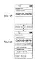
- FIGS. 15A and 15Bare views showing a display screen when there is an incoming call during music reproduction
- FIG. 16is a flowchart showing a processing procedure when there is an incoming call during music reproduction
- FIG. 17is a flowchart showing a processing procedure when a telephone number is inputted in a case of a setting at an outgoing/incoming call off mode
- FIG. 18is a flowchart showing a processing procedure when there is a recording request of an audio data
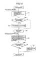
- FIG. 19is a flowchart showing a processing procedure when an electric field strength display is performed on a remote controller
- FIG. 20is a flowchart showing charge strength information to be displayed on a display of a remote controller
- FIG. 21is a flowchart showing a processing procedure when an incoming mail indicating display is performed on a remote controller.
- FIG. 22is a view showing incoming mail information to be displayed on a display of a remote controller.
- a portable telephone having a function of recording and reproducing an audio data(hereafter, referred to as a portable telephone) is described as an embodiment to which the present invention is applied.
- the following portable telephonehas a function of an electronic mail and searching for WEB through the Internet and a function of recording and reproducing an audio data since a memory card is mounted, as well as a normal telephone call function.
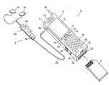
- FIG. 1shows an exterior perspective view of a portable telephone 1 in the embodiment of the present invention.
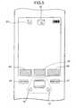
- FIG. 2shows a plan view of this portable telephone 1 .
- FIG. 3shows an enlarged view of the main portion of this portable telephone 1 .
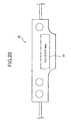
- the portable telephone 1is provided with a main body 2 which is substantially rectangular parallelepiped having main functions such as a telephone function and the like, and a remote controller unit 3 that has a remote operation function and an earphone microphone function of the main body 2 and can be disposed in the main body 2 .
- a voice output speaker 12is mounted at one end in a longitudinal direction on an operation surface 11 of the main body 2 , and a voice input microphone 13 is mounted at the other end in the longitudinal direction.
- the direction in which the speaker 12 is mountedis referred to as an upper portion, and the direction in which the microphone 13 is mounted is referred to as a lower direction.
- a rotation push switch 14is mounted at a substantial center in a short side direction of the operation surface 11 , between the speaker 12 and the microphone 13 on the operation surface 11 of the main body 2 .
- This rotation push switch 14is the switch that can be actuated by a rotating operation and also actuated by a pushing operation.
- This rotation push switch 14is designed such that its rotating operation direction is the upper and lower directions of the operation surface 11 (X and X′ directions shown in FIG. 3 ) and its pushing direction is the direction pushed vertically to the operation surface 11 (Y-direction shown in FIG. 3 ).
- a display 15 constituted by, for example, a liquid crystal display panelis mounted between the main body 2 and the rotation push switch 14 on the operation surface 11 of the main body 2 .
- a left soft key 16 and a right soft key 17are mounted between the display 15 and the rotation push switch 14 on the operation surface 11 of the main body 2 .
- the left soft key 16is mounted on a left side in a short side direction towards the operation surface 11
- the right soft key 17is mounted on a right side in the short side direction towards the operation surface 11 .
- a leftward direction key 18is mounted on a left adjacent side of the rotation push switch 14
- a rightward direction key 19is mounted on a right adjacent side thereof.
- a start key 21 to carry out a call start and the like, a clear key 22 , an end key 23 to carry out an end of a telephone outgoing and the like and twelve dial keys ( 0 to 9 and * and #) 24are mounted between the rotation push switch 14 and the microphone 13 on the operation surface 11 of the main body 2 .
- a manner key 25 to set a so-called manner mode for removing an incoming tone via a sound, and a memo key 26 to be used when a telephone number and the like are stored during a callare mounted between the dial keys ( 0 to 9 , and * and #) 24 and the microphone 13 on the operation surface 11 of the main body 2 .
- An antenna 31 for sending and receiving an electric wave to and from a base station for the portable telephoneis disposed on a side plane of an upper end of the main body 2 .
- An insertion slot 32 into which a memory card 4 is insertedis mounted on a side plane of a lower end of the main body 2 .
- a data input/output terminal 33 to send and receive data to and from a computer and the like, a line input terminal 34 to receive an audio data from an external audio apparatus, such as MD, CD, DVD or the like, and a remote controller unit terminal 35 to establish a connection to the remote controller unit 3are mounted on a side of a left side plane of the main body 2 .
- the remote controller unit 3will be described below.
- the remote controller unit 3is composed of an earphone microphone 41 , a remote controller 42 and a connection cable 43 .
- the earphone microphone 41is the unit into which an earphone and a microphone are integrated. The usage of this earphone microphone 41 enables a call to be carried out, for example, while the main body 2 is kept in a bag. The earphone microphone 41 is also used when audio data recorded on the memory card 4 is heard. This earphone microphone 41 is configured so as to be detachable from the remote controller 42 .
- a display unit 44 and an operation input unit 45are mounted in the remote controller 42 .
- the remote controller 42is intended to remotely operate the main body 2 .
- Such a remote controller unit 3can be operated when the remote controller 42 is connected through the connection cable 43 to the main body 2 .
- the remote controller unit 3can carry out the remote operations such as an incoming of a telephone, a reproduction, a stop and a fast forward of an audio signal, and the like.
- the main body 2 and the remote controller unit 3may send and receive a data through a wireless communication such as infrared rays and the like without any connection via a cable.
- FIG. 4is a functional block diagram of the portable telephone 1 .
- the main body 2 of the portable telephone 1is provided with the speaker 12 , the microphone 13 , the rotation operation switch 14 ; the display 15 , the various operation keys 16 to 26 , the antenna 31 , the insertion slot 32 , the data input output terminal 33 , the line input terminal 34 and the remote controller unit terminal 35 .
- this main body 2is composed of a transmission/reception unit 51 , a voice codec 52 , an audio encoder/decoder 53 , a memory card interface (memory card I/F) 54 , a digital data interface (digital I/F) 55 , a remote controller interface (remote controller I/F) 56 and a system controlling unit 57 .
- the remote controller unit 3is composed of the earphone microphone 41 , the remote controller 42 and the connection cable 43 .
- the remote controller 42 of the remote controller unit 3has the display 44 , the operation input unit 45 and a remote controller controlling unit 46 .
- the transmission/reception unit 51 of the main body 2carries out a process for transmitting an electric wave to the base station, and a process for receiving an electric wave from the base station.
- the transmission/reception unit 51demodulates the received electric wave through the antenna 31 , and sends the demodulated data to the voice codec 52 . Also, the transmission/reception unit 51 modulates the data sent from the voice codec 52 , and sends it through the antenna 31 .
- the voice codec 52encodes and decodes the voice data.
- the voice codec 52performs a voice decoding process on the demodulated data sent from the transmission/reception unit 51 .
- the voice signal on which the voice decoding process is performedis outputted from the speaker 12 , or sent through the remote controller I/F 56 to the remote controller unit 3 and outputted from the earphone microphone 41 .
- the voice codec 52receives the voice signal from the microphone 13 or the earphone microphone 41 , and encodes this voice signal and then sends to the transmission/reception unit 51 .
- the audio encoder/decoder 53performs an audio encoding/decoding process on audio data to be recorded on the memory card 4 .
- the audio data recorded on the memory card 4 inserted into the insertion slot 32is sent through the memory card I/F 54 to the audio encoder/decoder 53 .
- the audio encoder/decoder 53performs the decoding process, such as an encryption decoding process, a voice expanding process or the like, on the audio data.
- the audio data on which the decoding process is performedis sent through the remote controller I/F 56 to the remote controller unit 3 , and outputted from the earphone microphone 41 .
- the audio data inputted from an external portionis inputted through the data input output terminal 33 or the line input terminal 34 to the audio encoder/decoder 53 .
- the audio encoder/decoder 53performs the encoding process, such as a voice compressing process, an encryption decoding process or the like, on the inputted audio data.
- the audio data on which the encoding process is performedis recorded through the memory card I/F 54 on the memory card 4 inserted into the insertion slot 32 .
- the system controlling unit 57carries out the controls of each of the above-mentioned units.
- the remote controller controlling unit 46 in the remote controller 42 of the remote controller unit 3transmits and receives the data to and from the main body 2 , transmits and receives the signal to and from the earphone microphone 41 , controls the display on the display unit 44 , and controls the operational input from the operation input unit 45 .
- This portable telephone 1is the telephone of a wirelessly communicating system, and it is carried by a user.
- this portable telephone 1When this portable telephone 1 is located at a position at which the electric wave transmitted from the base station can be received, it becomes at a communicable state.
- the start key 21is pushed to start a call and then call out a partner.
- an incoming call from the partnercan be received. If there is the incoming call from the partner, any key is pushed to thereby start the call.
- an electric field strength indication 61 indicative of a level of an electric field strength of a received electric wave from the base stationis displayed at a predetermined position on a left upper side of the display 15 .
- the electric field strengthis detected by, for example, the transmission/reception unit 51 .
- the detected electric field strength informationis periodically read by the system controlling unit 57 .
- the system controlling unit 57carries out the display control of the display 15 on the basis of the read electric field strength information, and provides the electric field strength information to the user.
- this electric field strength indication 61is represented at approximately four stage levels, such as an excellent level, a usual level, a bad level and an incommunicable level, for example.
- this portable telephone 1has an electronic mail function of communicating with the base station and sending and receiving an electronic mail by using an Internet protocol.
- mail datais sent by displaying a predetermined mail input screen, and entering a sentence to be transmitted, and then selecting a mail transmission button when it is at the communicable state.
- the system controlling unit 57encodes the inputted electronic mail, and the transmission/reception unit 51 once sends the encoded mail data to the base station, and the mail data is transferred from the base station to a mail server of a partner.
- the base stationsends the mail data to the portable telephone 1 .
- the portable telephone 1when receiving the mail data at the time of the communicable state, automatically carries out an incoming mail process, and stores the mail data in an inner memory.
- the system controlling unit 57 of the portable telephone 1when obtaining the mail data from the base station, displays a mail incoming indication 62 at a predetermined position on the display 15 , as shown in FIG. 5 .
- this portable telephone 1has an Internet browsing function of communicating with the base station and viewing or a WEB site on the Internet.
- a browser screen of the InternetFor example, by displaying a browser screen of the Internet and then entering URL (Uniform Resource Locator) on this screen, communication with the base station is carried out, and a data provided through a predetermined URL is downloaded.
- URLUniform Resource Locator
- the memory card 4 on which audio data is recordedcan be attached and detached as necessary. It has a function of recording and reproducing the audio data, such as an operation for reproducing the audio data recorded on the memory card 4 and an operation for recording the audio data on this memory card 4 .
- the memory card 4When the audio data is reproduced, the memory card 4 is inserted into the insertion slot 32 , and a reproduction button is selected. When the reproduction button is selected, the audio data recorded on the memory card 4 in the insertion slot 32 is decoded by the audio encoder/decoder 53 , and outputted through the remote controller I/F 56 from the earphone microphone 41 .
- this portable telephone 1can record audio data received from an external computer or an external audio reproduction apparatus.
- the data input output terminal 33 and the external computerare connected to each other by using, for example, an IEEE 1394 interface and the like. Then, an application software on the external computer is used to carry out an operation for transferring desirable audio data to the memory card 4 (a so-called check-in operation). Accordingly, new audio data can be written on the memory card 4 .
- an operation for editing the audio data recorded on the memory card 4for example, a deletion of data, a rearrangement of a reproducing order or the like
- the line input terminal 34 and the external audio reproduction apparatusare connected through a cable to each other. Desirable audio data is reproduced by the audio reproduction apparatus, and a recording start command is given to the portable telephone 1 . Thus, a so-called dubbing is started. Then, new audio data can be written on the memory card 4 .
- the transfer of the signal to the line input terminal 34may be performed in a form of an analog signal or digital data. In a case of the analog signal being inputted, the audio encoder/decoder 53 carries out an A/D conversion, and converts the audio signal into the digital data. Then, the execution of the voice encoding process enables the audio data to be written on the memory card 4 .
- this portable telephone 1has the electronic mail function, the Internet browsing function and the function of recording and reproducing the audio data by using the memory card 4 , in addition to the usual telephone call function. In this way, there is provided the portable telephone intended to have multiple function.
- the rotation push switch 14is the switch that can be operated by a rotating operation and can be operated by a pushing operation.
- the rotating operation of the rotation push switch 14functions as, for example, the direction key for shifting upwardly and downwardly the pointer, such as the focus, the cursor or the like, which is displayed on the display 15 .
- the focusis, for example, the display to specify one piece of information (one icon, one menu title, one song title or the like) from information groups (for example, a plurality of icons, menu displays, list displays or the like) displayed on the display 15 .
- the display of the specified informationis highlighted or reversing displayed.
- This rotation push switch 14is mounted at the center in the short side direction on the operation surface 11 .
- the direction of the rotating operationis the upper and lower directions (the longitudinal direction) of the operation surface 11 .
- the shift of the focus on the display screenis parallel to the operation of an operating finger.
- the operating fingeris located oppositely to the display screen.
- the coincident feeling between the operational feeling and the screen operationis given to the user.
- the buttonssuch as the upper and lower keys and the like make the operation easy.
- the pushing operation of the rotation push switch 14has the function as the so-called soft key.
- the soft keyis a key in which an action when the button is pushed is changed in a programmable manner on the basis of the menu content and the information displayed on the display 15 .
- This soft keyis designed such that a content of a function selected when the button is pushed is displayed on the display 15 and the user can recognize the actual content of the action when this button is currently pushed.
- the function selected when this rotation push switch 14 is pushedis displayed as a central soft key function indication 63 , at a center on a lower side of the display screen of the display 15 , as shown in FIG. 5 .
- the left soft key 16functions as the above-mentioned soft key.
- a function selected when this left soft key 16 is pushedis displayed as a left soft key function indication 64 , at a left hand position on a lower side of the display screen of the display 15 , as shown in FIG. 5 .
- the right soft key 17also functions as the above-mentioned soft key.
- a function selected when this right soft key 17 is pushedis displayed as a right soft key function indication 65 , at a right hand position on a lower side of the display screen of the display 15 , as shown in FIG. 5 .
- the leftward direction key 18functions as a shift key to shift the focus and the cursor displayed on the display 15 to a leftward direction.
- the rightward direction key 19functions as a shift key to shift the focus and the cursor displayed on the display 15 to a rightward direction.
- the start key 21functions as a key to start a telephone call.
- the clear key 22functions as a key to switch a display state of the display screen to an initial display menu screen, or to clear input information.
- the end key 23functions as a key for terminating a call or a power supply unit key to carry out an end function of a telephone outgoing and turn on and off a power supply of the portable telephone 1 .
- the dial keys ( 0 to 9 and * and #) 24function as the input keys for numerals 0 to 9 and symbols * and #.
- various charactersare allocated thereto. Each of them functions as a character input key at a time of a character input of an electronic mail or the like. The kind of the allocated character is switched depending on a later-described character input mode setting screen.
- the kinds of the allocated charactersinclude, for example, a kanji (Chinese character), a double-byte (full size) kana (Japanese character), a double-byte (full size) alphabet, a double-byte (full size) numeral, a double-byte (full size) symbol (character letter or pictorial letter), a standard sentence format, a single-byte (half size) kana, a single-byte (half size) alphabet, a single-byte (half size) numeral, a single-byte (half size) of symbol (character letter or pictorial letter) and the like.
- the manner key 25functions as a key to set the manner mode of removing an incoming tone via a voice or sound.
- the memo key 26functions as a key to store a telephone number and the like during a call service.
- the manner key 25 and the memo key 26also have a page feed function of scrolling information displayed on the display 15 , correspondingly to one page.
- the manner key 25functions as an upward page feed key
- the memo key 26functions as a downward page feed key.
- the manner key 25is referred to as an upward page feed key 25
- the memo key 26is referred to as a downward page feed key 26 .
- the music order described hereimplies the number order of the numbers given to respective information units, for example, such as the numbers of tracks or the numbers of files recorded in a management information of a record medium. Typically, it corresponds to a reproducing order in a case of a continuous reproduction. Thus, even if the song order is rearranged, the actual content (audio data) recorded on the memory card 4 is not rewritten. The file number and the track number managed as the management information, or a link relation between songs (music pieces) or the like are rewritten.
- the audio datais reproduced. Once it is interrupted, a display screen is displayed as shown in FIG. 6A . If the left soft key 16 is pushed while this screen is displayed and “Function” is selected, an edition mode selection screen is displayed as shown in FIG. 6B .
- the rotation push switch 14is rotationally operated to shift a focus F upwardly and downwardly so that the focus F is located at a position of “Song Rearrangement”.
- a title list display screenis displayed as shown in FIG. 6C .
- the titles and the title numbers to specify the songs (pieces of music) recorded on the memory card 4are arranged in the upward and downward directions based on a song order currently being registered, and displayed in a form of list.
- the focus Fis firstly shifted from this state of the title list display screen to a position of a title of a song (music piece) desired to be shifted.
- the focus Fis shifted by rotationally operating the rotation push switch 14 since the title list is arranged in the upward and downward directions.
- FIG. 7Ait is assumed that the focus F is shifted to a position of “Title A”.
- the rotation push switch 14is pushed and operated to select “Selection”, “Title A” is selected as shown in FIG. 7B .
- the operational flowreturns back to a display screen in which the reproduction of the audio data is once stopped, as shown in FIG. 7E .
- “Completion”is selected by pushing the right soft key 17 from a state of FIG. 7D .
- the system controlling unit 57rewrites the management information of the memory card 4 in accordance with the order of the title list currently being displayed, and also returns the display screen back to the screen in which the reproduction of the audio data is once stopped, as shown in FIG. 7E .
- the title list in which the plurality of titles to specify the songs or music pieces recorded on the memory card 4 are arranged in accordance with the recording orderis displayed (Step S 11 ).
- the focusis shifted to a title position of a song desired to be shifted.
- the rotation push switch 14is operated in the pushing direction, and its title is selected (Step S 12 ).
- the title selected by operating the rotation push switch 14 in the rotating directionis shifted to any position on the list (Step S 13 ).
- the rotation push switch 14is operated in the pushing direction to thereby determine the shift destination of the title (Step S 14 ).
- Step S 15After the determination of the shift destination of the title, it is possible to operate the rotation push switch 14 in the rotating direction to thereby select a title of a next song or music piece desired to be shifted.
- the display of the title listis ended, and the order of recording the songs recorded on the memory card 4 is rewritten in accordance with the title list order (Step S 15 ).
- the editing workcan be very easily carried out by rearranging the recording order of the audio data recorded on the memory card 4 in accordance with such an operational procedure.
- the target for the rearrangementis not limited to the audio data. It may be applied to any information, if it is the information to define a recording order, for example, such as a picture data, a computer data, a telephone number list, an address list and the like.
- the memory card 4is exemplified as a recording medium. However, it may be any medium if it is a rewritable recording medium, such as the inner memory of the portable telephone 1 , MD, and DVD-RAM.
- a plurality of character kindsare assigned to the dial keys 24 . Any character kind of a character can be entered by switching the character input mode.
- a character input mode selection screenis displayed as shown in FIG. 9A .
- the character kinds assigned to the dial keys 24include, for example, a kanji (Chinese character), a double-byte (full size) kana, a double-byte (full size) alphabet, a double-byte (full size) numeral, a double-byte (full size) symbol (character letter or pictorial letter), a standard sentence format, a single-byte (half size) kana, a single-byte (half size) alphabet, a single-byte (half size) numeral, and a single-byte (half size) symbol (character letter of pictorial letter).
- a kanjiChoinese character
- a double-byte (full size) kanaa double-byte (full size) alphabet
- a double-byte (full size) numerala double-byte (full size) symbol (character letter or pictorial letter)
- a standard sentence formata single-byte (half size) kana, a single-byte (half size) alphabet, a single-byte (
- a kanji (Chinese character)top column
- a double-byte kanasecond upper column
- a double-byte alphabetthird upper column
- a double-byte numeralthird lower column
- a double-byte symbolcharacter letter or pictorial letter
- a standard sentence formatbottom column
- a single-byte kanasecond upper column
- a single-byte alphabetthird upper column
- a single-byte numeralthird lower column
- a single-byte symbolcharacter letter of pictorial letter
- the rotating operation of the rotation push switch 14enables the focus F to be cyclically shifted in an order of a kanji ⁇ a double-byte kana ⁇ a double-byte alphabet ⁇ a double-byte numeral ⁇ a double-byte symbol (character) ⁇ a standard sentence format ⁇ a single-byte kana ⁇ a single-byte alphabet ⁇ a single-byte numeral ⁇ a single-byte symbol (character) ⁇ a kanji ⁇ a double-byte kana and so on, as shown in FIG. 9B .
- pushing the leftward direction key 18 or the rightward direction key 19causes the focus F to be shifted between the left and right columns.
- the character input mode selection screenin which all the character kinds are displayed is displayed.
- the selection of a character kind based on this character input mode selection screenenables the character of any character kind assigned to the dial keys 24 to be entered.
- the character input modecan be easily selected without any troublesome work such as an operation for pushing the mode set buttons, one by one, and then switching the character input mode.
- the character input mode selection screenit may be designed to display only the character kind that can be entered at that time or select only the character kind that can be entered at that time. For example, when an electronic mail address or URL is entered, it is possible to design the character input mode selection screen so that only a half size of alphabet and a half size of numeral can be selected.
- a guidance display of a shiftable direction of a focus or the like and a guidance display of a page feed keywill be described below.
- a direction key guidance displayis carried out for indicating whether or not the rotation push switch 14 can be rotationally operated and whether or not the leftward direction key 18 and the rightward direction key 19 can be operated. That is, the direction key guidance display indicates whether or not the pointer such as the focus, the cursor and the like can be effectively shifted upwardly and downwardly by rotationally operating the rotation push switch 14 and whether or not the pointer such as the focus, the cursor and the like can be effectively shifted in the leftward and rightward directions by operating the leftward direction key 18 and the rightward direction key 19 .
- This direction key guidance displayis constituted by an upwardly shiftable mark 71 , a downwardly shiftable mark 72 , a leftwardly shiftable mark 73 and a rightwardly shiftable mark 74 , as shown in FIG. 10 .
- Those direction key guidance displaysare displayed as respective arrow marks around a central soft key function indication 63 . That is, the upwardly shiftable mark 71 is displayed as an upward arrow mark at an upper position of the central soft key function indication 63 .
- the downwardly shiftable mark 72is displayed as a downward arrow mark at a lower position of the central soft key function indication 63 .
- the leftwardly shiftable mark 73is displayed as a left arrow mark at a left position of the central soft key function indication 63 .
- the rightwardly shiftable mark 74is displayed as a rightward arrow mark at a right position of the central soft key function indication 63 .
- the upwardly shiftable mark 71is displayed if the rotation push switch 14 can be upwardly operated, and it is not displayed if the rotation push switch 14 cannot be upwardly operated.
- the upwardly shiftable mark 71is displayed, for example, if the focus F can be shifted in a direction of an arrow “a” in FIG. 10 (i.e., for example, if a selectable information exists at a further upper position of the focused information), and it is not displayed if the focus F can not be shifted in the direction of the arrow “a” in FIG. 10 (i.e., for example, if the selectable information does not exist at the further upper position of the focused information.
- the downwardly shiftable mark 72is displayed if the rotation push switch 14 can be downwardly operated, and it is not displayed if the rotation push switch 14 cannot be downwardly operated.
- the downwardly shiftable mark 72is displayed, for example, if the focus F can be shifted in a direction of an arrow “b” in FIG. 10 (i.e., for example, if a selectable information exists at a further lower position of the focused information), and it is not displayed if the focus F cannot be shifted in the direction of the arrow “b” in FIG. 10 (i.e., for example, if the selectable information does not exist at the further lower position of the focused information).
- the leftwardly shiftable mark 73is displayed if the leftward direction key 18 can be operated in the leftward direction, and it is not displayed if the leftward direction key 18 cannot be operated in the leftward direction.
- the leftwardly shiftable mark 73is displayed, for example, if the focus F can be shifted in a direction of an arrow “c” in FIG. 10 (i.e., for example, if a selectable information exists at a further leftward position of the focused information or if there is a screen of an upper hierarchy of the selected information), and it is not displayed if the focus F can not be shifted in the direction of the arrow “c” in FIG. 10 (i.e., for example, if the selectable information does not exist at the further leftward position of the focused information or if there is not the screen of the upper hierarchy of the selected information).
- the rightwardly shiftable mark 74is displayed if the rightward direction key 19 can be operated in the rightward direction, and it is not displayed if the rightward direction key 19 cannot be operated in the rightward direction. That is, the rightwardly shiftable mark 74 is displayed, for example, if the focus F can be shifted in a direction of an arrow “d” in FIG. 10 (i.e., for example, if a selectable information exists at a further rightward position of the focused information or if there is a screen of a lower hierarchy of the selected information), and it is not displayed if the focus F can not be shifted in the direction of the arrow “d” in FIG. 10 (i.e., for example, if the selectable information does not exist at the further rightward position of the focused information or if there is not the screen of the lower hierarchy of the selected information).
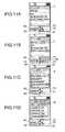
- FIGS. 11A to 11Dare views showing a jump menu that is a short cut screen to each display menu.
- FIG. 11Ais a display screen of a state at which when a jump menu screen is displayed, the focus F points out a character string of “Jump” of its menu title.
- the upwardly shiftable mark 71 , the downwardly shiftable mark 72 and the leftwardly shiftable mark 73are displayed at the state of this display screen.
- Pushing the rightward direction key 19 on the display screen of FIG. 11Aresults in a display screen of FIG. 11B .
- This display screen of FIG. 11Bis a selection screen showing an individual menu within the jump menu, and it is a screen of a state at which the focus F points out a selection position of “Internet”.
- the upwardly shiftable mark 71 , the downwardly shiftable mark 72 , the leftwardly shiftable mark 73 and the rightwardly shiftable mark 74are displayed on this display screen.
- Pushing the left soft key 16 on the display screen of FIG. 11Bresults in a display screen of FIG. 11C .
- This display screen of FIG. 11Cis an edition screen showing an individual menu within the jump menu.
- the upwardly shiftable mark 71 and the downwardly shiftable mark 72are displayed on this display screen. At this time, it is possible to shift the focus F upwardly and downwardly by rotating the rotation push switch 14 .
- Pushing the right soft key 17 on the display screen of FIG. 11Bresults in a display screen of FIG. 11D .
- This display screen of FIG. 11Dis an addition screen of an individual menu display within the jump menu.
- the upwardly shiftable mark 71 , the downwardly shiftable mark 72 and the leftwardly shiftable mark 73are displayed on this display screen.
- a division line 75 indicative of a head of a listis displayed on this display screen of FIG. 11D .
- the division line 75 indicative of the head of this listis used in the following manner, for example. That is, there is a case that although the number of displayed lists is definite, the focus is desired to be cyclically shifted by the rotating operation of the rotation push switch 14 , namely, there is a case that the focus is desired to be shifted in order to make the focus coincide with the lowest portion of the list by instructing the further upward direction even if the focus coincides with the uppermost portion of the list. If the cyclic focus shift is carried out as mentioned above, a portion at which the head of the list is located cannot be evidently provided to the user. Accordingly, this portable telephone 1 is designed such that the division line 75 is displayed at the upper most division position of the list.
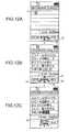
- FIGS. 12A to 12Care views showing an input screen of an electronic mail.
- FIG. 12Ais a display screen when even one character is not still written to a main body of a mail, and a cursor C is located on a left upper portion.
- the downwardly shiftable mark 72 and the rightwardly shiftable mark 74are displayed on this display screen.
- FIG. 12Bis a display screen under a condition that the main body of the mail is written to a certain degree.
- the characters on the display shown in FIG. 12B and FIG. 12Care in Japanese in order to explain the character conversion function of the portable telephone of the present embodiment.
- the sentences shown in these figuresmeans “ ⁇ won 16—the game between ⁇ and ⁇ in ⁇ dome with score of 5-2. Winning pitcher was XX (not shown) who has won five games and lost three games in this season.”
- the last word in the fifth row, which is shown with an underline,has just been currently inputted to be converted into a word with kanji.
- the upwardly shiftable mark 71 , downwardly shiftable mark 72 , the leftwardly shiftable mark 73 and the rightwardly shiftable mark 74are displayed on this display screen.
- the cursor Cwill appear after the converted word.
- FIG. 12Cis a display screen when the word underlined in FIG. 12B has been converted into one of word with kanji (Chinese character).
- a conversion candidate display 76is displayed for indicating that a conversion candidate is outputted by rotationally operating the rotation push switch 14 .
- a page feed guidance displayis also carried out for indicating whether or not a previous page feed can be done by using the upward page feed key 25 or whether or not a next page feed can be done by using the downward page feed key 26 .
- the page feed guidance displayis the information to indicate whether or not the operation of the upward page feed key 25 or the downward page feed key 26 enables a page to be fed, namely, whether or not there is further information, currently invisible, beyond the display screen.
- This page feed guidance displayis constituted by an upwardly feedable page mark 77 and a downwardly feedable page mark 78 , as shown in FIG. 13 .
- Those page feed guidance displaysare displayed at upper and lower positions on the left side of the display screen, respectively.
- the upwardly feedable page mark 77is displayed if the page feed can be upwardly done by using the upward page feed key 25 , and it is not displayed if the operation is impossible.
- the downwardly feedable page mark 78is displayed if the page feed can be downwardly done by using the downward page feed key 26 , and it is not displayed if the operation is impossible.
- FIGS. 14A to 14Bare views showing an input screen of an electronic mail.
- FIG. 14Ais a display screen when the cursor is located at the position of the second character on the first row, under a condition that the main body of the mail is written to a certain degree.
- the downwardly feedable page mark 78is displayed on this display screen. At this time, it is possible to scroll the page downwardly by pushing the downward page feed key 26 .
- FIG. 14Bis a display screen when the page is downwardly scrolled correspondingly to one page from the state of FIG. 14A .
- the upwardly feedable page mark 77 and the downwardly feedable page mark 78are displayed on this display screen. At this time, it is possible to scroll the page upwardly by pushing the upward page feed key 25 . Also, it is possible to scroll the page downwardly by pushing the downward page feed key 26 .
- such executions of the direction key guidance display and the page feed key guidance displaycan improve the operational performances of the direction keys and the page feed keys and accordingly improve the convenience of the user.
- Step S 21When the portable telephone 1 receives an incoming call from a partner during an audio reproduction (Step S 21 ), a display screen is displayed as shown in FIG. 15A . At this time, if any key except the left soft key 16 is pushed (Step S 22 ), the incoming call is received to start a call. Here, if the call is started, the audio reproduction is transiently suspended (Step S 23 ). Also, when there is the incoming call, and the left soft key 16 is pushed (Step S 22 ), a menu is displayed as shown in FIG. 15B (Step S 24 ).
- a menu displayis carried out for indicating “Forward to Answer Service”, “Incoming Call Forwarding”, “Answer Holding” and “Answer Rejection”.
- the rotation push switch 14is rotationally operated to then select any one of the menus (Steps S 25 , S 26 ).
- a processis carried out for forwarding the telephone call from the partner to a telephone answer service station installed in the base station.
- Incoming Call Forwardinga process is carried out for forwarding the telephone call from the partner to another telephone number.
- Answer Holdinga state at which the incoming call from the partner is held is maintained (namely, the calling state is held).
- Answer Rejectiona process is carried out for disconnecting the telephone call from the partner.
- the portable telephone 1if there is the incoming call during the audio reproduction, the rejection of the call is done depending on the operational input. Due to this mechanism, in the portable telephone 1 , the simple operation enables the reproduction to be continued if there is the incoming call during the audio reproduction.
- an outgoing/incoming call off modecan be set so as not to transmit and receive an electric wave by stopping the operation of the transmission/reception unit 51 .
- this outgoing/incoming call off modeis selected, for example, on the menu screen, the system controlling unit 57 stops a protocol operation of the transmission/reception unit 51 , and perfectly stops transmitting and receiving the electric wave to and from the base station.
- Such setting of the outgoing/incoming call off modecan stop only the transmission and reception of the electric wave without turning off the power supply of the main body. Thus, it can be set at the state that the functions except the telephone function can be used.
- the telephone functioncannot be used at this outgoing/incoming call off mode, it is possible to carry out the input operation of the character of the electronic mail, the recording and the reproduction of the music, and the like other operations.
- Step S 31If the outgoing/incoming call off mode is set, when the dial key 24 is pushed and a telephone number is inputted (Step S 31 ), the system controlling unit 57 displays the pushed telephone number on the display 15 (Step S 32 ).
- Step S 33the system controlling unit 57 judges whether or not its telephone number inputted is one of emergency phone call numbers (for example, in a case of Japan, 110 for police, 118 for coast guard and 119 for fire station and/or ambulance) or a pre-registered predetermined telephone number (Step S 34 ).
- the registered telephone numberis desired to be different from a usual address registration, and it is desired to be a telephone number specially registered for an emergency.
- Step S 35If the telephone number inputted is not one of the emergency phone call numbers or the pre-registered telephone number, the outgoing call is stopped, and the outgoing/incoming call off mode is maintained in its original state (Step S 35 ). That is, a phone call cannot be made.
- the system controlling unit 57cancels the outgoing/incoming call off mode, and then actuates the protocol process of the operation of the transmission reception unit 51 (Step S 36 ).
- the transmission/reception unit 51starts an operation for capturing a base station.
- the transmission/reception unit 51When the transmission/reception unit 51 captures the base station, the transmission/reception unit 51 starts a process for transmitting an input telephone number (Step S 38 ).
- this portable telephone 1even if it is set at the outgoing/incoming call off mode at which the transmission/reception of the electric wave is stopped and the outgoing/incoming of a call is not done, if a phone call of emergency or a preliminarily registered phone call is made, a call can be started without canceling operation of the outgoing/incoming call off mode by the user. Thus, it is possible to immediately make a report or make a call.
- the audio data inputted from the line input terminal 34 or the data input/output terminal 33can be recorded on the memory card 4 .
- a process when there is a request for recording audio data in the portable telephone 1is described with reference to FIG. 18 .
- the system controlling unit 57obtains information of a protocol operation state of the transmission/reception unit 51 , and stores it in a memory (Step S 42 ).
- the system controlling unit 57judges whether or not the protocol for the transmission/reception of the transmission/reception circuit 51 is currently operated (Step S 43 ). If the protocol is operated, the operational flow proceeds to step S 44 . If it is not operated, the operational flow proceeds to step S 45 .
- the system controlling unit 57if the protocol of the transmission/reception circuit 51 is operated, stops the operation of the protocol of this transmission reception circuit 51 , and sets at the portable phone 1 at the outgoing/incoming call off mode in which the outgoing/incoming of the telephone call is not carried out.
- the system controlling unit 57starts the operation for recording the audio data (Step S 45 ).
- the operation for recording the audio data at this step S 45is always carried out at the state at which it is set at the outgoing/incoming call off mode.
- the system controlling unit 57if there is a record stop request (Step S 46 ), obtains a protocol operation state of the transmission/reception circuit 51 prior to the actuation of the recording operation stored in the memory at the previous step S 42 (Step S 47 ).
- Step S 48It judges whether or not the protocol is under operation, from the information read out at the step S 47 (Step S 48 ). If the protocol is under operation, the operational flow proceeds to step S 49 . If it is not under operation, the process is ended.
- the system controlling unit 57if the protocol of the transmission/reception circuit 51 is under operation, starts the operation of the protocol of the transmission/reception circuit 51 (Step S 49 ). Then, the series of audio recording processes is ended.
- the interference in the recording operation caused by the incoming callcan be avoided by automatically setting it at the outgoing/incoming call off mode, if there is the recording operation request.
- the remote controller unit 3is mounted as mentioned above.
- the remote controller 42 in this remote controller unit 3carries out a remote control for reproducing the audio data recorded on the memory card 4 and a remote control for the function of the main body of the portable telephone.
- Step S 61If the user requests a display of electric field strength (Step S 61 ), the remote controller controlling unit 46 of the remote controller 42 sends a report request of the electric field strength to the system controlling unit 57 (Step S 62 ).
- the system controlling unit 57 of the main body 2sends electric field strength information currently being held (the information for displaying the electric field strength indication 61 ) and a timeout timer value to the remote controller 42 (Step S 63 ).
- the remote controller controlling unit 46 of the remote controller 42judges whether or not any indication is currently displayed on the display unit 44 of the remote controller 42 (Step S 64 ). If any indication is displayed on the display unit 44 , the operational flow proceeds to step S 65 . If it is not displayed, the operational flow proceeds to step S 66 .
- the remote controller controlling unit 46 of the remote controller 42transiently saves the information currently being displayed on the display unit 44 (Step S 65 ).
- the remote controller controlling unit 46 of the remote controller 42displays the electric field strength on the display unit 44 , based on the electric field strength information sent out from the system controlling unit 57 of the main body 2 (Step S 66 ).
- the electric field strength informationis displayed on the display unit 44 at approximately four stage levels, for example, such as an excellent level, a usual level, a bad level and an impossible communication.
- the indicationis not limited to such four-stage-level display, and any other way for indicating the electric field strength may be employed.
- the remote controller controlling unit 46 of the remote controller 42actuates a timer (Step S 67 ).
- the actuated timercarries out counting until a counted value reaches the timeout timer value sent out from the system controlling unit 57 of the main body 2 . If the counting is ended, a timer event is generated.
- Step S 68If the timer event is generated from the timer (Step S 68 ).
- the remote controller controlling unit 46 of the remote controller 42judges whether or not there is the save information transiently saved at the step S 65 (Step S 69 ). If there is the save information, the operational flow proceeds to step S 70 . If there is not the save information, the operational flow proceeds to step S 71 .
- Step S 70the remote controller controlling unit 46 of the remote controller 42 again displays the save information, and ends the process. Also, the remote controller controlling unit 46 of the remote controller 42 , if there is not the save information, removes the indication on the display unit 44 , and ends the process (Step S 71 ).
- timeout timer valueis not sent out from the main body 2 and that it is set in advance on the remote controller side.
- the portable telephone 1has the remote controller unit 3 separately mounted from the main body 2 , and the electric field strength information is displayed on this remote controller unit 3 .
- This mechanism of the portable telephone 1enables the electric field strength of the received electric wave to be simply and conveniently checked by the user. For example, even if the main body 2 of the portable telephone is kept in a bag or the like, the electric field strength information is displayed on, for example, the remote controller unit 3 .
- the usercan check a current electric wave reception state very simply without especially taking out the main body 2 from the bag or the like to check the status.
- the electric field strength informationis not always displayed on the remote controller unit 3 . That is, it is displayed, as necessary, in accordance with the operation from the user. Hence, it is possible to effectively use the display region placed on the remote controller unit 3 .
- the remote controller unit 3is disposed as mentioned above.
- the remote controller 42 of this remote controller unit 3carries out the remote control for reproducing the audio data recorded on the memory card 4 and the remote control to the function of the main body 2 of the portable telephone.
- Step S 81When automatically receiving a mail data from the base station (Step S 81 ), the system controlling unit 57 of the main body 2 sends out a mail incoming display report and a timeout timer value to the remote controller 42 (Step S 82 ).
- the remote controller controlling unit 46 of the remote controller 42judges whether or not any indication is currently displayed on the display unit 44 of the remote controller 42 (Step S 83 ). If any indication is displayed on the display unit 44 , the operational flow proceeds to step S 84 . If it is not displayed, the operational flow proceeds to step S 85 .
- the remote controller controlling unit 46 of the remote controller 42transiently saves the information currently being displayed on the display unit 44 (Step S 84 ).
- the remote controller controlling unit 46 of the remote controller 42displays the mail incoming indicative of the presence of the mail incoming (Step S 85 ).
- This incoming indicationis displayed, for example, such as “You've Got Mail”, as shown in FIG. 22 .
- the remote controller controlling unit 46 of the remote controller 42actuates the timer (Step S 86 ). Then, the actuated timer carries out counting until a counted value reaches the timeout timer value sent out from the system controlling unit 57 of the main body 2 . When the count is ended, the timer event is generated.
- Step S 87the remote controller controlling unit 46 of the remote controller 42 judges whether or not there is the save information transiently saved at the step S 84 (Step S 88 ). If there is the save information, the operational flow proceeds to step S 89 . If there is not the save information, the operational flow proceeds to step S 90 .
- Step S 89when there is the save information, again displays the save information, the remote controller controlling unit 46 of the remote controller 42 , and ends the process. Also, the remote controller controlling unit 46 of the remote controller 42 , when there is not the save information, removes the indication on the display unit 44 , and ends the process (Step S 90 ).
- timeout timer valueis not sent out from the main body 2 and that it is set in advance on the remote controller side.
- the portable telephone 1has the remote controller unit 3 separately mounted from the main body 2 , and the fact of the incoming of the electronic mail is displayed on this remote controller unit 3 .
- This mechanism of the portable telephone 1which is a characteristic feature of the invention enables the fact of the incoming of the electronic mail to be quickly reported to the user. Also, the user can easily recognize the fact of the incoming of the electronic mail. In the portable telephone 1 , for example, even if the main body 2 is kept in a bag or the like, the mail incoming is displayed on, for example, the display of the remote controller unit 3 . Thus, the user can recognize the fact of the incoming of the electronic mail quickly and easily without especially checking the main body 2 .
Landscapes
- Engineering & Computer Science (AREA)
- General Engineering & Computer Science (AREA)
- Theoretical Computer Science (AREA)
- Human Computer Interaction (AREA)
- Computer Networks & Wireless Communication (AREA)
- Signal Processing (AREA)
- Physics & Mathematics (AREA)
- General Physics & Mathematics (AREA)
- Business, Economics & Management (AREA)
- General Business, Economics & Management (AREA)
- Mobile Radio Communication Systems (AREA)
- Telephone Function (AREA)
- Telephone Set Structure (AREA)
- User Interface Of Digital Computer (AREA)
- Input From Keyboards Or The Like (AREA)
- Controls And Circuits For Display Device (AREA)
- Position Input By Displaying (AREA)
Abstract
Description
Claims (25)
Priority Applications (2)
| Application Number | Priority Date | Filing Date | Title |
|---|---|---|---|
| US13/530,197US8842106B2 (en) | 2000-08-11 | 2012-06-22 | Portable telephone |
| US14/460,983US9942377B2 (en) | 2000-08-11 | 2014-08-15 | Portable telephone |
Applications Claiming Priority (5)
| Application Number | Priority Date | Filing Date | Title |
|---|---|---|---|
| JP2000245401AJP4806840B2 (en) | 2000-08-11 | 2000-08-11 | Mobile phone |
| JP2000-245401 | 2000-08-11 | ||
| US09/927,050US7405722B2 (en) | 2000-08-11 | 2001-08-09 | Portable telephone |
| US11/606,587US9459763B2 (en) | 2000-08-11 | 2006-11-30 | Portable telephone |
| US13/530,197US8842106B2 (en) | 2000-08-11 | 2012-06-22 | Portable telephone |
Related Parent Applications (1)
| Application Number | Title | Priority Date | Filing Date |
|---|---|---|---|
| US11/606,587ContinuationUS9459763B2 (en) | 2000-08-11 | 2006-11-30 | Portable telephone |
Related Child Applications (1)
| Application Number | Title | Priority Date | Filing Date |
|---|---|---|---|
| US14/460,983ContinuationUS9942377B2 (en) | 2000-08-11 | 2014-08-15 | Portable telephone |
Publications (2)
| Publication Number | Publication Date |
|---|---|
| US20120256826A1 US20120256826A1 (en) | 2012-10-11 |
| US8842106B2true US8842106B2 (en) | 2014-09-23 |
Family
ID=18735937
Family Applications (6)
| Application Number | Title | Priority Date | Filing Date |
|---|---|---|---|
| US09/927,050Expired - LifetimeUS7405722B2 (en) | 2000-08-11 | 2001-08-09 | Portable telephone |
| US11/606,587Expired - Fee RelatedUS9459763B2 (en) | 2000-08-11 | 2006-11-30 | Portable telephone |
| US11/788,439Expired - LifetimeUS7580006B2 (en) | 2000-08-11 | 2007-04-20 | Portable telephone |
| US12/818,292Expired - LifetimeUS7978150B2 (en) | 2000-08-11 | 2010-06-18 | Portable telephone |
| US13/217,982Expired - LifetimeUS9075504B2 (en) | 2000-08-11 | 2011-08-25 | Portable telephone |
| US13/530,197Expired - Fee RelatedUS8842106B2 (en) | 2000-08-11 | 2012-06-22 | Portable telephone |
Family Applications Before (5)
| Application Number | Title | Priority Date | Filing Date |
|---|---|---|---|
| US09/927,050Expired - LifetimeUS7405722B2 (en) | 2000-08-11 | 2001-08-09 | Portable telephone |
| US11/606,587Expired - Fee RelatedUS9459763B2 (en) | 2000-08-11 | 2006-11-30 | Portable telephone |
| US11/788,439Expired - LifetimeUS7580006B2 (en) | 2000-08-11 | 2007-04-20 | Portable telephone |
| US12/818,292Expired - LifetimeUS7978150B2 (en) | 2000-08-11 | 2010-06-18 | Portable telephone |
| US13/217,982Expired - LifetimeUS9075504B2 (en) | 2000-08-11 | 2011-08-25 | Portable telephone |
Country Status (6)
| Country | Link |
|---|---|
| US (6) | US7405722B2 (en) |
| EP (4) | EP2804364B1 (en) |
| JP (1) | JP4806840B2 (en) |
| KR (1) | KR100808319B1 (en) |
| CN (1) | CN1152544C (en) |
| DE (1) | DE60128520T2 (en) |
Cited By (1)
| Publication number | Priority date | Publication date | Assignee | Title |
|---|---|---|---|---|
| US9942377B2 (en)* | 2000-08-11 | 2018-04-10 | Drnc Holdings, Inc. | Portable telephone |
Families Citing this family (37)
| Publication number | Priority date | Publication date | Assignee | Title |
|---|---|---|---|---|
| JP4806840B2 (en) | 2000-08-11 | 2011-11-02 | ソニー株式会社 | Mobile phone |
| US20020046315A1 (en)* | 2000-10-13 | 2002-04-18 | Interactive Objects, Inc. | System and method for mapping interface functionality to codec functionality in a portable audio device |
| US11204729B2 (en) | 2000-11-01 | 2021-12-21 | Flexiworld Technologies, Inc. | Internet based digital content services for pervasively providing protected digital content to smart devices based on having subscribed to the digital content service |
| US10915296B2 (en)* | 2000-11-01 | 2021-02-09 | Flexiworld Technologies, Inc. | Information apparatus that includes a touch sensitive screen interface for managing or replying to e-mails |
| US10860290B2 (en) | 2000-11-01 | 2020-12-08 | Flexiworld Technologies, Inc. | Mobile information apparatuses that include a digital camera, a touch sensitive screen interface, support for voice activated commands, and a wireless communication chip or chipset supporting IEEE 802.11 |
| AU2002239325A1 (en) | 2000-11-20 | 2002-05-27 | Flexiworld Technologies, Inc. | Systems and methods for mobile and pervasive output |
| US20020099884A1 (en) | 2001-01-19 | 2002-07-25 | Chang William Ho | Output controller systems and method for universal data output |
| JP3585468B2 (en) | 2002-02-28 | 2004-11-04 | 株式会社コナミコンピュータエンタテインメント東京 | GAME DEVICE, PROGRAM, AND GAME DEVICE CONTROL METHOD |
| KR100465289B1 (en)* | 2002-04-22 | 2005-01-13 | 삼성전자주식회사 | Device and method for displaying thumbnail screen in wireless terminal having a camera |
| KR100467871B1 (en)* | 2002-10-01 | 2005-01-24 | 삼성전자주식회사 | Key button for portable radiotelephone |
| US20040185774A1 (en)* | 2003-03-21 | 2004-09-23 | Scott Bryan A | System, device, and method for receving satellite radio on a handheld computing device |
| JP2005123973A (en)* | 2003-10-17 | 2005-05-12 | Nec Corp | Portable telephone and recording control method therefor |
| US8055361B2 (en)* | 2003-11-13 | 2011-11-08 | Samsung Electronics Co., Ltd. | Memory expansion pack for providing content to portable terminal |
| US7657562B2 (en)* | 2003-12-24 | 2010-02-02 | Panasonic Corporation | Data processing apparatus and data processing method |
| JP2005189674A (en)* | 2003-12-26 | 2005-07-14 | Seiko Epson Corp | Image display output apparatus, printing apparatus including the same, and image display output method |
| KR100940207B1 (en)* | 2003-12-30 | 2010-02-10 | 삼성전자주식회사 | Mouse pointing method and control device |
| US8965457B2 (en)* | 2004-08-09 | 2015-02-24 | Blackberry Limited | Method and apparatus for controlling an electronic device display for presenting information on said display |
| JP4574329B2 (en)* | 2004-11-10 | 2010-11-04 | 株式会社デンソー | Image display device |
| US20060139328A1 (en) | 2004-12-29 | 2006-06-29 | Nina Maki | Mobile communications terminal and a method therefor |
| KR100684918B1 (en)* | 2005-04-01 | 2007-02-22 | 삼성전자주식회사 | Mobile communication terminal and method for playing music file |
| KR100675179B1 (en)* | 2005-05-16 | 2007-01-30 | 엘지전자 주식회사 | Scroll input device of mobile communication terminal |
| KR100698316B1 (en) | 2006-01-10 | 2007-03-22 | 엘지전자 주식회사 | Character input method and device |
| US7860538B2 (en)* | 2006-02-28 | 2010-12-28 | Lg Electronics Inc. | Mobile terminal |
| US7996050B2 (en)* | 2006-02-28 | 2011-08-09 | Lg Electronics Inc. | Input device for an electronic device and electronic device having the same |
| US20070250792A1 (en)* | 2006-04-24 | 2007-10-25 | Lavery Andrew J | Presentation of service data in support of a user interactive application program during running of the program on a computer controlled display |
| KR101144804B1 (en)* | 2006-07-03 | 2012-05-11 | 엘지전자 주식회사 | Mobile communication device including rotary key and operation control method thereof |
| KR101345662B1 (en)* | 2006-10-26 | 2014-01-27 | 엘지전자 주식회사 | Method for indicating broadcasting-related information and mobile terminal capable of receiving broadcasting using the same |
| EP1959238B1 (en)* | 2007-02-13 | 2018-05-23 | Harman Becker Automotive Systems GmbH | Method for inputting a destination in a navigation unit and nagivation system therefor |
| US7860489B2 (en)* | 2007-03-26 | 2010-12-28 | Research In Motion Limited | System and method for providing a user interface for managing calls received at a mobile device |
| US7983722B2 (en)* | 2007-03-29 | 2011-07-19 | Research In Motion Limited | Headset with multi-button control for a mobile communication device |
| USD596630S1 (en)* | 2007-10-29 | 2009-07-21 | Sony Ericsson Mobile Communications Japan, Inc. | Mobile phone |
| JP2011113483A (en)* | 2009-11-30 | 2011-06-09 | Fujitsu Ten Ltd | Information processor, audio device, and information processing method |
| CN104023254A (en)* | 2013-03-01 | 2014-09-03 | 联想(北京)有限公司 | Information processing method and electronic equipment |
| CN104427088A (en)* | 2013-08-22 | 2015-03-18 | 深圳富泰宏精密工业有限公司 | Communication notification control system and method |
| CN103780990A (en)* | 2014-01-23 | 2014-05-07 | 上海斐讯数据通信技术有限公司 | Headset with display function and display method |
| JP2017092967A (en)* | 2016-12-12 | 2017-05-25 | ディーアールエヌシー ホールディングス インコーポレイテッド | Radio communication device, radio communication method, radio communication control device, and program |
| CN109272736B (en)* | 2018-11-29 | 2024-05-14 | 珠海格力电器股份有限公司 | Voice remote controller and voice remote control household appliance |
Citations (90)
| Publication number | Priority date | Publication date | Assignee | Title |
|---|---|---|---|---|
| JPS61179646A (en) | 1985-02-05 | 1986-08-12 | Oki Electric Ind Co Ltd | Telephone call inhibiting circuit |
| JPS62140545A (en) | 1985-12-16 | 1987-06-24 | Tamura Electric Works Ltd | Key telephone system |
| US4803487A (en)* | 1987-04-30 | 1989-02-07 | Motorola, Inc. | Portable communications receiver with separate information presentation means |
| JPH02119489A (en) | 1988-10-28 | 1990-05-07 | Matsushita Electric Ind Co Ltd | television receiver |
| JPH03179938A (en) | 1989-12-08 | 1991-08-05 | Alpine Electron Inc | Automobile telephone system |
| US5095308A (en) | 1990-01-09 | 1992-03-10 | Southern Marine Research, Inc. | Transceiver with battery saver and method of using same |
| JPH056958A (en) | 1990-11-30 | 1993-01-14 | Toshiba Corp | Semiconductor device |
| JPH0575769A (en) | 1991-09-17 | 1993-03-26 | Ricoh Co Ltd | Digital multifunction machine |
| JPH05204335A (en) | 1992-01-28 | 1993-08-13 | Casio Comput Co Ltd | Liquid crystal display |
| JPH06104812A (en) | 1992-09-24 | 1994-04-15 | Toshiba Corp | Mobile radio telephone |
| JPH06205274A (en) | 1992-12-28 | 1994-07-22 | Canon Inc | Communications system |
| JPH0818347A (en) | 1994-06-27 | 1996-01-19 | Rohm Co Ltd | Power save circuit |
| US5493703A (en)* | 1993-07-23 | 1996-02-20 | Nec Corporation | Portable radio device with on-vehicle adaptor system |
| US5537608A (en) | 1992-11-13 | 1996-07-16 | International Business Machines Corporation | Personal communicator apparatus |
| US5561712A (en)* | 1991-06-11 | 1996-10-01 | Nec Corporation | Hands free phone set with hand held remote control for controlling telephonic functions |
| US5659594A (en)* | 1989-09-25 | 1997-08-19 | Fujitsu Limited | Mobile telephone system capable of adapting a portable telephone set |
| JPH09223291A (en) | 1996-02-16 | 1997-08-26 | Yamatake Honeywell Co Ltd | Portable setting device |
| US5675524A (en) | 1993-11-15 | 1997-10-07 | Ete Inc. | Portable apparatus for providing multiple integrated communication media |
| JPH09321839A (en) | 1996-05-29 | 1997-12-12 | Saitama Nippon Denki Kk | Portable telephone set provided with flip mechanism |
| EP0831414A2 (en) | 1996-09-19 | 1998-03-25 | Nec Corporation | A portable radio terminal |
| US5749052A (en) | 1995-05-24 | 1998-05-05 | Tele Digital Development, Inc. | Cellular telephone management system |
| US5758295A (en) | 1994-03-16 | 1998-05-26 | Telefonaktiebolget Lm Ericsson | Uniform man-machine interface for cellular mobile telephones |
| US5774540A (en)* | 1995-11-15 | 1998-06-30 | Lucent Technologies Inc. | Hierarchical menu screen interface for displaying and accessing telephone terminal features |
| JPH10200938A (en) | 1997-01-07 | 1998-07-31 | Toshiba Corp | Communication control device |
| US5802460A (en)* | 1996-07-22 | 1998-09-01 | Sony Corporation | Telephone handset with remote controller for transferring information to a wireless messaging device |
| US5809432A (en)* | 1994-12-30 | 1998-09-15 | Nec Corporation | Portable radio terminal having a removable radio system unit |
| US5815407A (en) | 1995-12-14 | 1998-09-29 | Motorola Inc. | Method and device for inhibiting the operation of an electronic device during take-off and landing of an aircraft |
| US5825353A (en) | 1995-04-18 | 1998-10-20 | Will; Craig Alexander | Control of miniature personal digital assistant using menu and thumbwheel |
| JPH10304430A (en) | 1997-04-28 | 1998-11-13 | Sony Corp | Communication control method and communication controller |
| US5867796A (en)* | 1995-04-28 | 1999-02-02 | Nec Corporation | Portable telephone set capable of being put in a holding mode by operation of a vibration unit which is for announcing reception of an incoming call to a user |
| WO1999009711A1 (en) | 1997-08-21 | 1999-02-25 | Ericsson Inc. | Apparatus for enabling and disabling a wireless communication device incorporated within a mobile computer |
| US5878353A (en)* | 1994-08-29 | 1999-03-02 | Motorola, Inc. | Radio frequency communication device including a mirrored surface |
| JPH1198244A (en) | 1997-09-22 | 1999-04-09 | Toshiba Corp | Method of restricting use of telephone function by notification of caller telephone number and portable device with mobile telephone function |
| JPH11168540A (en) | 1997-09-04 | 1999-06-22 | Nokia Mobile Phones Ltd | Portable telephone set provided with navigation key for handset |
| US5924044A (en)* | 1997-02-26 | 1999-07-13 | Motorola, Inc. | Modular communication device and method of providing communications therewith |
| KR19990061622A (en) | 1997-12-31 | 1999-07-26 | 김영환 | Mobile terminal and method of providing short message service with easy operation |
| WO1999045459A1 (en) | 1998-03-05 | 1999-09-10 | Mitsubishi Denki Kabushiki Kaisha | Portable terminal |
| US5960367A (en)* | 1995-09-18 | 1999-09-28 | Casio Computer Co., Ltd. | Incoming calling system |
| JPH11284700A (en) | 1998-03-27 | 1999-10-15 | Matsushita Electric Ind Co Ltd | Mobile terminal |
| US5973612A (en) | 1996-09-19 | 1999-10-26 | Microsoft Corporation | Flexible object notification |
| GB2337897A (en) | 1998-04-08 | 1999-12-01 | Nec Corp | Battery saving arrangement for mobile phone with power controlled RF amplifier |
| JPH11514482A (en) | 1995-07-26 | 1999-12-07 | ソニー エレクトロニクス インク | Recording media player |
| JP2000040970A (en) | 1998-07-23 | 2000-02-08 | Nec Corp | Portable communication device and storage medium with program stored therein |
| US6032050A (en) | 1994-05-20 | 2000-02-29 | Fujitsu Limited | Method for standby control in a mobile telecommunications network setting standby conditions conforming to different modes of communication and mobile unit using same |
| JP2000069561A (en)* | 1998-08-25 | 2000-03-03 | Kyocera Corp | Remote control system for wireless communication terminals |
| JP2000115324A (en) | 1998-10-02 | 2000-04-21 | Toshiba Corp | Mobile terminal device |
| US6058164A (en) | 1995-03-01 | 2000-05-02 | Fujitsu Limited | Mode-switchable telephone and mode setting and switching methods for the same |
| JP2000151455A (en) | 1998-11-06 | 2000-05-30 | Kenwood Corp | Mobile telephone set and radio communication equipment |
| JP2000156812A (en) | 1998-11-19 | 2000-06-06 | Nikon Corp | Camera with communication function |
| EP1009142A2 (en) | 1998-12-08 | 2000-06-14 | Nokia Mobile Phones Ltd. | Wireless communication device and a control means |
| JP2000231371A (en) | 1999-02-11 | 2000-08-22 | Sony Internatl Europ Gmbh | Radio communication terminal device and display method for icon |
| JP2000259304A (en) | 1999-03-04 | 2000-09-22 | Phone.Com Japan Kk | Application launcher for two-way mobile communication device |
| US6125283A (en) | 1998-05-18 | 2000-09-26 | Ericsson Inc. | Multi-mode mobile terminal and methods for operating the same |
| US6128012A (en) | 1996-09-19 | 2000-10-03 | Microsoft Corporation | User interface for a portable data management device with limited size and processing capability |
| KR20000060078A (en) | 1999-03-11 | 2000-10-16 | 서평원 | Mobile terminal having improved structure |
| US6215993B1 (en) | 1999-02-24 | 2001-04-10 | Ericsson Inc. | Caller ID preview for mobile telephones |
| US6216017B1 (en)* | 1997-11-06 | 2001-04-10 | Samsung Electronics Co., Ltd. | Separable cellular telephone and method for operating the same |
| US6216266B1 (en)* | 1999-10-28 | 2001-04-10 | Hughes Electronics Corporation | Remote control signal level meter |
| US6272359B1 (en)* | 1996-10-31 | 2001-08-07 | Nokia Mobile Phones Ltd. | Personal mobile communications device having multiple units |
| JP2001309024A (en) | 2000-04-19 | 2001-11-02 | Seiko Instruments Inc | Radio equipment |
| KR20010098792A (en) | 2000-04-27 | 2001-11-08 | 이데이 노부유끼 | Rotatively-operated switch apparatus and communication terminal apparatus |
| JP2001333173A (en) | 2000-05-23 | 2001-11-30 | Kenwood Corp | Mobile communication terminal |
| JP2002055762A (en) | 2000-08-11 | 2002-02-20 | Sony Corp | Portable electronic equipment |
| JP2002057760A (en) | 2000-08-11 | 2002-02-22 | Sony Corp | Portable telephone set |
| JP2002057757A (en) | 2000-08-11 | 2002-02-22 | Sony Corp | Portable telephone set |
| JP2002057756A (en) | 2000-08-11 | 2002-02-22 | Sony Corp | Portable telephone set |
| JP2002057751A (en) | 2000-08-11 | 2002-02-22 | Sony Corp | Portable telephone set |
| JP2002057761A (en) | 2000-08-11 | 2002-02-22 | Sony Corp | Portable telephone set |
| JP2002058072A (en) | 2000-08-11 | 2002-02-22 | Sony Corp | Portable telephone |
| US6408177B1 (en) | 2000-02-09 | 2002-06-18 | Ss8 Networks, Inc. | System and method for call management with voice channel conservation |
| US6425018B1 (en) | 1998-02-27 | 2002-07-23 | Israel Kaganas | Portable music player |
| US6424820B1 (en)* | 1999-04-02 | 2002-07-23 | Interval Research Corporation | Inductively coupled wireless system and method |
| US6453182B1 (en) | 2000-02-15 | 2002-09-17 | Qualcomm, Incorporated | Wireless telephone airplane and alarm clock modes |
| US6459911B1 (en)* | 1998-09-30 | 2002-10-01 | Nec Corporation | Portable telephone equipment and control method therefor |
| US6470196B1 (en) | 1998-10-09 | 2002-10-22 | Nec Corporation | Portable communication apparatus |
| US20030013432A1 (en) | 2000-02-09 | 2003-01-16 | Kazunari Fukaya | Portable telephone and music reproducing method |
| US6510207B1 (en) | 1999-06-29 | 2003-01-21 | Agere Systems Inc. | Voice messaging system storage of emergency alert system warnings |
| US6606506B1 (en) | 1998-11-19 | 2003-08-12 | Albert C. Jones | Personal entertainment and communication device |
| US6625478B1 (en) | 1999-03-01 | 2003-09-23 | Sony Corporation | Multifunction wireless telephone |
| US6662022B1 (en) | 1999-04-19 | 2003-12-09 | Sanyo Electric Co., Ltd. | Portable telephone set |
| US6681120B1 (en) | 1997-03-26 | 2004-01-20 | Minerva Industries, Inc., | Mobile entertainment and communication device |
| US6687497B1 (en) | 2000-02-11 | 2004-02-03 | Sony Electronics Inc. | Method, system, and structure for disabling a communication device during the occurrence of one or more predetermined conditions |
| US6760759B1 (en) | 1999-11-24 | 2004-07-06 | Mtel Limited | System to support mobile visual communications |
| US6950126B1 (en) | 1998-11-19 | 2005-09-27 | Nikon Corporation | Camera capable of communicating with other communication device |
| US6985754B1 (en) | 1999-04-26 | 2006-01-10 | Nokia Mobile Phones Limited | Radio terminal for browsing the internet |
| US7016707B2 (en)* | 2000-06-21 | 2006-03-21 | Seiko Epson Corporation | Mobile telephone and radio communication device cooperatively processing incoming call |
| US7123936B1 (en) | 1998-02-18 | 2006-10-17 | Ericsson Inc. | Cellular phone with expansion memory for audio and video storage |
| US7348961B1 (en) | 1999-02-26 | 2008-03-25 | Jonathan Shneidman | Telescreen operating method |
| US7405722B2 (en) | 2000-08-11 | 2008-07-29 | Sony Corporation | Portable telephone |
| US7634299B2 (en) | 2004-09-02 | 2009-12-15 | Pioneer Corporation | Communication terminal apparatus, method of changing function and/or setting of communication terminal apparatus, and program |
Family Cites Families (13)
| Publication number | Priority date | Publication date | Assignee | Title |
|---|---|---|---|---|
| AU589400B2 (en)* | 1985-03-05 | 1989-10-12 | Wang Laboratories, Inc. | Apparatus and method for control of one computer system by another computer system |
| JPS6410A (en) | 1987-02-10 | 1989-01-05 | Koshii Purezaabingu:Kk | Phoxim emulsion resistant to discoloration and production thereof |
| DD285649A5 (en) | 1989-10-12 | 1990-12-19 | ������@������������k�� | METHOD FOR CONTROLLING THE WORKING SPEED OF PROCESSING MACHINES |
| JP3159321B2 (en) | 1991-01-17 | 2001-04-23 | ソニー株式会社 | Mobile phone |
| US5329578A (en) | 1992-05-26 | 1994-07-12 | Northern Telecom Limited | Personal communication service with mobility manager |
| JP3025190B2 (en)* | 1996-03-06 | 2000-03-27 | リーダー電子株式会社 | How to measure and collect electric field strength |
| US6161021A (en) | 1998-05-11 | 2000-12-12 | Sony Corporation | Remote notification control in wireless communication device |
| US6246879B1 (en)* | 1998-07-07 | 2001-06-12 | Telefonaktiebolaget L M Ericsson (Publ) | Methods of sharing capabilities information between the nodes of telecommunications network |
| JP2000078301A (en) | 1998-08-31 | 2000-03-14 | Kyocera Corp | Mobile phone |
| US6259436B1 (en)* | 1998-12-22 | 2001-07-10 | Ericsson Inc. | Apparatus and method for determining selection of touchable items on a computer touchscreen by an imprecise touch |
| US6345180B1 (en) | 1998-12-30 | 2002-02-05 | Ericsson Inc. | Mobile terminal reserve power system |
| JP2000209363A (en) | 1999-01-19 | 2000-07-28 | Sony Corp | Processor and method for information processing and provision medium |
| US6757372B1 (en)* | 2000-01-10 | 2004-06-29 | Cisco Technology, Inc. | User interface for a network-enabled telephone |
- 2000
- 2000-08-11JPJP2000245401Apatent/JP4806840B2/ennot_activeExpired - Fee Related
- 2001
- 2001-08-07EPEP14164835.2Apatent/EP2804364B1/ennot_activeExpired - Lifetime
- 2001-08-07EPEP01306750Apatent/EP1179944B1/ennot_activeExpired - Lifetime
- 2001-08-07EPEP10003280.4Apatent/EP2194695B1/ennot_activeExpired - Lifetime
- 2001-08-07EPEP06021187Apatent/EP1764984A3/ennot_activeCeased
- 2001-08-07DEDE60128520Tpatent/DE60128520T2/ennot_activeExpired - Lifetime
- 2001-08-09USUS09/927,050patent/US7405722B2/ennot_activeExpired - Lifetime
- 2001-08-11KRKR1020010048503Apatent/KR100808319B1/ennot_activeExpired - Fee Related
- 2001-08-11CNCNB01133200XApatent/CN1152544C/ennot_activeExpired - Fee Related
- 2006
- 2006-11-30USUS11/606,587patent/US9459763B2/ennot_activeExpired - Fee Related
- 2007
- 2007-04-20USUS11/788,439patent/US7580006B2/ennot_activeExpired - Lifetime
- 2010
- 2010-06-18USUS12/818,292patent/US7978150B2/ennot_activeExpired - Lifetime
- 2011
- 2011-08-25USUS13/217,982patent/US9075504B2/ennot_activeExpired - Lifetime
- 2012
- 2012-06-22USUS13/530,197patent/US8842106B2/ennot_activeExpired - Fee Related
Patent Citations (99)
| Publication number | Priority date | Publication date | Assignee | Title |
|---|---|---|---|---|
| JPS61179646A (en) | 1985-02-05 | 1986-08-12 | Oki Electric Ind Co Ltd | Telephone call inhibiting circuit |
| JPS62140545A (en) | 1985-12-16 | 1987-06-24 | Tamura Electric Works Ltd | Key telephone system |
| US4803487A (en)* | 1987-04-30 | 1989-02-07 | Motorola, Inc. | Portable communications receiver with separate information presentation means |
| JPH02119489A (en) | 1988-10-28 | 1990-05-07 | Matsushita Electric Ind Co Ltd | television receiver |
| US5659594A (en)* | 1989-09-25 | 1997-08-19 | Fujitsu Limited | Mobile telephone system capable of adapting a portable telephone set |
| JPH03179938A (en) | 1989-12-08 | 1991-08-05 | Alpine Electron Inc | Automobile telephone system |
| US5095308A (en) | 1990-01-09 | 1992-03-10 | Southern Marine Research, Inc. | Transceiver with battery saver and method of using same |
| JPH056958A (en) | 1990-11-30 | 1993-01-14 | Toshiba Corp | Semiconductor device |
| US5561712A (en)* | 1991-06-11 | 1996-10-01 | Nec Corporation | Hands free phone set with hand held remote control for controlling telephonic functions |
| JPH0575769A (en) | 1991-09-17 | 1993-03-26 | Ricoh Co Ltd | Digital multifunction machine |
| JPH05204335A (en) | 1992-01-28 | 1993-08-13 | Casio Comput Co Ltd | Liquid crystal display |
| JPH06104812A (en) | 1992-09-24 | 1994-04-15 | Toshiba Corp | Mobile radio telephone |
| US5537608A (en) | 1992-11-13 | 1996-07-16 | International Business Machines Corporation | Personal communicator apparatus |
| JPH06205274A (en) | 1992-12-28 | 1994-07-22 | Canon Inc | Communications system |
| US5493703A (en)* | 1993-07-23 | 1996-02-20 | Nec Corporation | Portable radio device with on-vehicle adaptor system |
| US5675524A (en) | 1993-11-15 | 1997-10-07 | Ete Inc. | Portable apparatus for providing multiple integrated communication media |
| US5758295A (en) | 1994-03-16 | 1998-05-26 | Telefonaktiebolget Lm Ericsson | Uniform man-machine interface for cellular mobile telephones |
| US6032050A (en) | 1994-05-20 | 2000-02-29 | Fujitsu Limited | Method for standby control in a mobile telecommunications network setting standby conditions conforming to different modes of communication and mobile unit using same |
| JPH0818347A (en) | 1994-06-27 | 1996-01-19 | Rohm Co Ltd | Power save circuit |
| US5878353A (en)* | 1994-08-29 | 1999-03-02 | Motorola, Inc. | Radio frequency communication device including a mirrored surface |
| US5809432A (en)* | 1994-12-30 | 1998-09-15 | Nec Corporation | Portable radio terminal having a removable radio system unit |
| US6058164A (en) | 1995-03-01 | 2000-05-02 | Fujitsu Limited | Mode-switchable telephone and mode setting and switching methods for the same |
| US5825353A (en) | 1995-04-18 | 1998-10-20 | Will; Craig Alexander | Control of miniature personal digital assistant using menu and thumbwheel |
| US5867796A (en)* | 1995-04-28 | 1999-02-02 | Nec Corporation | Portable telephone set capable of being put in a holding mode by operation of a vibration unit which is for announcing reception of an incoming call to a user |
| US5749052A (en) | 1995-05-24 | 1998-05-05 | Tele Digital Development, Inc. | Cellular telephone management system |
| US6128625A (en) | 1995-07-26 | 2000-10-03 | Sony Corporation | Method and apparatus for operating a database |
| JPH11514482A (en) | 1995-07-26 | 1999-12-07 | ソニー エレクトロニクス インク | Recording media player |
| US6388958B1 (en) | 1995-07-26 | 2002-05-14 | Sony Corporation | Method of building a play list for a recorded media changer |
| US5960367A (en)* | 1995-09-18 | 1999-09-28 | Casio Computer Co., Ltd. | Incoming calling system |
| US5774540A (en)* | 1995-11-15 | 1998-06-30 | Lucent Technologies Inc. | Hierarchical menu screen interface for displaying and accessing telephone terminal features |
| US5815407A (en) | 1995-12-14 | 1998-09-29 | Motorola Inc. | Method and device for inhibiting the operation of an electronic device during take-off and landing of an aircraft |
| JPH09223291A (en) | 1996-02-16 | 1997-08-26 | Yamatake Honeywell Co Ltd | Portable setting device |
| JPH09321839A (en) | 1996-05-29 | 1997-12-12 | Saitama Nippon Denki Kk | Portable telephone set provided with flip mechanism |
| US5802460A (en)* | 1996-07-22 | 1998-09-01 | Sony Corporation | Telephone handset with remote controller for transferring information to a wireless messaging device |
| US6128012A (en) | 1996-09-19 | 2000-10-03 | Microsoft Corporation | User interface for a portable data management device with limited size and processing capability |
| EP0831414A2 (en) | 1996-09-19 | 1998-03-25 | Nec Corporation | A portable radio terminal |
| US5973612A (en) | 1996-09-19 | 1999-10-26 | Microsoft Corporation | Flexible object notification |
| US6272359B1 (en)* | 1996-10-31 | 2001-08-07 | Nokia Mobile Phones Ltd. | Personal mobile communications device having multiple units |
| JPH10200938A (en) | 1997-01-07 | 1998-07-31 | Toshiba Corp | Communication control device |
| US5924044A (en)* | 1997-02-26 | 1999-07-13 | Motorola, Inc. | Modular communication device and method of providing communications therewith |
| US6681120B1 (en) | 1997-03-26 | 2004-01-20 | Minerva Industries, Inc., | Mobile entertainment and communication device |
| JPH10304430A (en) | 1997-04-28 | 1998-11-13 | Sony Corp | Communication control method and communication controller |
| WO1999009711A1 (en) | 1997-08-21 | 1999-02-25 | Ericsson Inc. | Apparatus for enabling and disabling a wireless communication device incorporated within a mobile computer |
| US6097964A (en) | 1997-09-04 | 2000-08-01 | Nokia Mobile Phones Limited | Navigation key for a handset |
| JPH11168540A (en) | 1997-09-04 | 1999-06-22 | Nokia Mobile Phones Ltd | Portable telephone set provided with navigation key for handset |
| JPH1198244A (en) | 1997-09-22 | 1999-04-09 | Toshiba Corp | Method of restricting use of telephone function by notification of caller telephone number and portable device with mobile telephone function |
| US6216017B1 (en)* | 1997-11-06 | 2001-04-10 | Samsung Electronics Co., Ltd. | Separable cellular telephone and method for operating the same |
| KR19990061622A (en) | 1997-12-31 | 1999-07-26 | 김영환 | Mobile terminal and method of providing short message service with easy operation |
| US7123936B1 (en) | 1998-02-18 | 2006-10-17 | Ericsson Inc. | Cellular phone with expansion memory for audio and video storage |
| US6425018B1 (en) | 1998-02-27 | 2002-07-23 | Israel Kaganas | Portable music player |
| EP1004957A1 (en) | 1998-03-05 | 2000-05-31 | Mitsubishi Denki Kabushiki Kaisha | Portable terminal |
| WO1999045459A1 (en) | 1998-03-05 | 1999-09-10 | Mitsubishi Denki Kabushiki Kaisha | Portable terminal |
| US6332024B1 (en) | 1998-03-05 | 2001-12-18 | Mitsubishi Denki Kabushiki Kaisha | Portable terminal |
| JPH11284700A (en) | 1998-03-27 | 1999-10-15 | Matsushita Electric Ind Co Ltd | Mobile terminal |
| GB2337897A (en) | 1998-04-08 | 1999-12-01 | Nec Corp | Battery saving arrangement for mobile phone with power controlled RF amplifier |
| US6125283A (en) | 1998-05-18 | 2000-09-26 | Ericsson Inc. | Multi-mode mobile terminal and methods for operating the same |
| JP2000040970A (en) | 1998-07-23 | 2000-02-08 | Nec Corp | Portable communication device and storage medium with program stored therein |
| JP2000069561A (en)* | 1998-08-25 | 2000-03-03 | Kyocera Corp | Remote control system for wireless communication terminals |
| US6459911B1 (en)* | 1998-09-30 | 2002-10-01 | Nec Corporation | Portable telephone equipment and control method therefor |
| JP2000115324A (en) | 1998-10-02 | 2000-04-21 | Toshiba Corp | Mobile terminal device |
| US6470196B1 (en) | 1998-10-09 | 2002-10-22 | Nec Corporation | Portable communication apparatus |
| JP2000151455A (en) | 1998-11-06 | 2000-05-30 | Kenwood Corp | Mobile telephone set and radio communication equipment |
| JP2000156812A (en) | 1998-11-19 | 2000-06-06 | Nikon Corp | Camera with communication function |
| US6950126B1 (en) | 1998-11-19 | 2005-09-27 | Nikon Corporation | Camera capable of communicating with other communication device |
| US6606506B1 (en) | 1998-11-19 | 2003-08-12 | Albert C. Jones | Personal entertainment and communication device |
| US6571086B1 (en) | 1998-12-08 | 2003-05-27 | Nokia Mobile Phones Ltd. | Wireless communication device and a control means |
| EP1009142A2 (en) | 1998-12-08 | 2000-06-14 | Nokia Mobile Phones Ltd. | Wireless communication device and a control means |
| JP2000231371A (en) | 1999-02-11 | 2000-08-22 | Sony Internatl Europ Gmbh | Radio communication terminal device and display method for icon |
| US6600936B1 (en) | 1999-02-11 | 2003-07-29 | Sony International (Europe) Gmbh | Terminal for wireless telecommunication and method for displaying icons on a display of such a terminal |
| KR20000062539A (en) | 1999-02-11 | 2000-10-25 | 소니 인터내셔널(유로파) 게엠베하 | Terminal for wireless telecommunication and method for displaying icons on a display of such a terminal |
| US6215993B1 (en) | 1999-02-24 | 2001-04-10 | Ericsson Inc. | Caller ID preview for mobile telephones |
| US7348961B1 (en) | 1999-02-26 | 2008-03-25 | Jonathan Shneidman | Telescreen operating method |
| US6625478B1 (en) | 1999-03-01 | 2003-09-23 | Sony Corporation | Multifunction wireless telephone |
| JP2000259304A (en) | 1999-03-04 | 2000-09-22 | Phone.Com Japan Kk | Application launcher for two-way mobile communication device |
| KR20000060078A (en) | 1999-03-11 | 2000-10-16 | 서평원 | Mobile terminal having improved structure |
| US6424820B1 (en)* | 1999-04-02 | 2002-07-23 | Interval Research Corporation | Inductively coupled wireless system and method |
| US6662022B1 (en) | 1999-04-19 | 2003-12-09 | Sanyo Electric Co., Ltd. | Portable telephone set |
| US6985754B1 (en) | 1999-04-26 | 2006-01-10 | Nokia Mobile Phones Limited | Radio terminal for browsing the internet |
| US6510207B1 (en) | 1999-06-29 | 2003-01-21 | Agere Systems Inc. | Voice messaging system storage of emergency alert system warnings |
| US6216266B1 (en)* | 1999-10-28 | 2001-04-10 | Hughes Electronics Corporation | Remote control signal level meter |
| US6760759B1 (en) | 1999-11-24 | 2004-07-06 | Mtel Limited | System to support mobile visual communications |
| US6408177B1 (en) | 2000-02-09 | 2002-06-18 | Ss8 Networks, Inc. | System and method for call management with voice channel conservation |
| US20030013432A1 (en) | 2000-02-09 | 2003-01-16 | Kazunari Fukaya | Portable telephone and music reproducing method |
| US6687497B1 (en) | 2000-02-11 | 2004-02-03 | Sony Electronics Inc. | Method, system, and structure for disabling a communication device during the occurrence of one or more predetermined conditions |
| US6453182B1 (en) | 2000-02-15 | 2002-09-17 | Qualcomm, Incorporated | Wireless telephone airplane and alarm clock modes |
| JP2001309024A (en) | 2000-04-19 | 2001-11-02 | Seiko Instruments Inc | Radio equipment |
| KR20010098792A (en) | 2000-04-27 | 2001-11-08 | 이데이 노부유끼 | Rotatively-operated switch apparatus and communication terminal apparatus |
| JP2001333173A (en) | 2000-05-23 | 2001-11-30 | Kenwood Corp | Mobile communication terminal |
| US7016707B2 (en)* | 2000-06-21 | 2006-03-21 | Seiko Epson Corporation | Mobile telephone and radio communication device cooperatively processing incoming call |
| JP2002057751A (en) | 2000-08-11 | 2002-02-22 | Sony Corp | Portable telephone set |
| JP2002057760A (en) | 2000-08-11 | 2002-02-22 | Sony Corp | Portable telephone set |
| JP2002055762A (en) | 2000-08-11 | 2002-02-20 | Sony Corp | Portable electronic equipment |
| JP2002057757A (en) | 2000-08-11 | 2002-02-22 | Sony Corp | Portable telephone set |
| JP2002057756A (en) | 2000-08-11 | 2002-02-22 | Sony Corp | Portable telephone set |
| JP2002057761A (en) | 2000-08-11 | 2002-02-22 | Sony Corp | Portable telephone set |
| JP2002058072A (en) | 2000-08-11 | 2002-02-22 | Sony Corp | Portable telephone |
| US7405722B2 (en) | 2000-08-11 | 2008-07-29 | Sony Corporation | Portable telephone |
| US7580006B2 (en) | 2000-08-11 | 2009-08-25 | Sony Corporation | Portable telephone |
| US7634299B2 (en) | 2004-09-02 | 2009-12-15 | Pioneer Corporation | Communication terminal apparatus, method of changing function and/or setting of communication terminal apparatus, and program |
Non-Patent Citations (2)
| Title |
|---|
| 3Com Corporation, "Handbook for the Palm III(TM) Organizer", Copyright © 1998, 232 pages. |
| 3Com Corporation, "Handbook for the Palm III™ Organizer", Copyright © 1998, 232 pages. |
Cited By (1)
| Publication number | Priority date | Publication date | Assignee | Title |
|---|---|---|---|---|
| US9942377B2 (en)* | 2000-08-11 | 2018-04-10 | Drnc Holdings, Inc. | Portable telephone |
Also Published As
| Publication number | Publication date |
|---|---|
| US7405722B2 (en) | 2008-07-29 |
| CN1338853A (en) | 2002-03-06 |
| US20120256826A1 (en) | 2012-10-11 |
| US20070218943A1 (en) | 2007-09-20 |
| HK1204176A1 (en) | 2015-11-06 |
| EP1179944B1 (en) | 2007-05-23 |
| US7580006B2 (en) | 2009-08-25 |
| DE60128520T2 (en) | 2008-01-31 |
| US20020067352A1 (en) | 2002-06-06 |
| US7978150B2 (en) | 2011-07-12 |
| JP4806840B2 (en) | 2011-11-02 |
| KR20020013793A (en) | 2002-02-21 |
| EP1764984A3 (en) | 2007-03-28 |
| EP1179944A3 (en) | 2004-01-14 |
| US20110312302A1 (en) | 2011-12-22 |
| US9075504B2 (en) | 2015-07-07 |
| US20100255888A1 (en) | 2010-10-07 |
| EP2804364B1 (en) | 2017-10-04 |
| EP2194695A1 (en) | 2010-06-09 |
| US20070070055A1 (en) | 2007-03-29 |
| DE60128520D1 (en) | 2007-07-05 |
| EP1764984A2 (en) | 2007-03-21 |
| US9459763B2 (en) | 2016-10-04 |
| KR100808319B1 (en) | 2008-02-27 |
| JP2002062859A (en) | 2002-02-28 |
| EP1179944A2 (en) | 2002-02-13 |
| EP2194695B1 (en) | 2014-01-01 |
| CN1152544C (en) | 2004-06-02 |
| EP2804364A1 (en) | 2014-11-19 |
Similar Documents
| Publication | Publication Date | Title |
|---|---|---|
| US8842106B2 (en) | Portable telephone | |
| JPH0833049A (en) | Portable wireless communication device | |
| US6362814B1 (en) | Electronic apparatus | |
| US9942377B2 (en) | Portable telephone | |
| JP2002057756A (en) | Portable telephone set | |
| JP2002057751A (en) | Portable telephone set | |
| JP2002055762A (en) | Portable electronic equipment | |
| JP2002057761A (en) | Portable telephone set | |
| JP2002057757A (en) | Portable telephone set | |
| JP2002058072A (en) | Portable telephone | |
| JP2002057760A (en) | Portable telephone set | |
| HK1204176B (en) | Mobile phone | |
| JP5115772B2 (en) | RADIO COMMUNICATION DEVICE, RADIO COMMUNICATION METHOD, RADIO COMMUNICATION CONTROL DEVICE, PROGRAM | |
| JP2002132609A (en) | Communication terminal, program storage medium and recording medium | |
| JP2016149773A (en) | Radio communication device, radio communication method, radio communication control device, and program | |
| JP2017092967A (en) | Radio communication device, radio communication method, radio communication control device, and program | |
| JP2014220848A (en) | Radio communication device, radio communication method, radio communication control device and program | |
| JP2013225852A (en) | Radio communication device, radio communication method, radio communication control device and program | |
| JP2012124942A (en) | Radio communication device, radio communication method, radio communication control device and program | |
| JPH08265816A (en) | Character editor and pager | |
| KR20060085072A (en) | Music file playback method of mobile communication terminal | |
| JP2002342005A (en) | Character input method and character input device |
Legal Events
| Date | Code | Title | Description |
|---|---|---|---|
| AS | Assignment | Owner name:SONY CORPORATION OF AMERICA, NEW YORK Free format text:ASSIGNMENT OF ASSIGNORS INTEREST;ASSIGNOR:SONY CORPORATION;REEL/FRAME:030212/0803 Effective date:20121219 Owner name:DRNC HOLDINGS, INC., DELAWARE Free format text:ASSIGNMENT OF ASSIGNORS INTEREST;ASSIGNOR:INTERDIGITAL HOLDINGS, INC.;REEL/FRAME:030213/0026 Effective date:20130327 Owner name:INTERDIGITAL HOLDINGS, INC., DELAWARE Free format text:ASSIGNMENT OF ASSIGNORS INTEREST;ASSIGNOR:SONY CORPORATION OF AMERICA;REEL/FRAME:030212/0888 Effective date:20130125 Owner name:SONY CORPORATION, JAPAN Free format text:ASSIGNMENT OF ASSIGNORS INTEREST;ASSIGNOR:TAKEUCHI, RYOSUKE;REEL/FRAME:030212/0711 Effective date:20011015 | |
| STCF | Information on status: patent grant | Free format text:PATENTED CASE | |
| MAFP | Maintenance fee payment | Free format text:PAYMENT OF MAINTENANCE FEE, 4TH YEAR, LARGE ENTITY (ORIGINAL EVENT CODE: M1551) Year of fee payment:4 | |
| FEPP | Fee payment procedure | Free format text:MAINTENANCE FEE REMINDER MAILED (ORIGINAL EVENT CODE: REM.); ENTITY STATUS OF PATENT OWNER: LARGE ENTITY | |
| LAPS | Lapse for failure to pay maintenance fees | Free format text:PATENT EXPIRED FOR FAILURE TO PAY MAINTENANCE FEES (ORIGINAL EVENT CODE: EXP.); ENTITY STATUS OF PATENT OWNER: LARGE ENTITY | |
| STCH | Information on status: patent discontinuation | Free format text:PATENT EXPIRED DUE TO NONPAYMENT OF MAINTENANCE FEES UNDER 37 CFR 1.362 | |
| FP | Lapsed due to failure to pay maintenance fee | Effective date:20220923 |