US8840677B2 - Allograft bone plugs, systems and techniques - Google Patents
Allograft bone plugs, systems and techniquesDownload PDFInfo
- Publication number
- US8840677B2 US8840677B2US12/945,156US94515610AUS8840677B2US 8840677 B2US8840677 B2US 8840677B2US 94515610 AUS94515610 AUS 94515610AUS 8840677 B2US8840677 B2US 8840677B2
- Authority
- US
- United States
- Prior art keywords
- implant
- bone
- distal
- proximal
- central axis
- Prior art date
- Legal status (The legal status is an assumption and is not a legal conclusion. Google has not performed a legal analysis and makes no representation as to the accuracy of the status listed.)
- Active, expires
Links
- 210000000988bone and boneAnatomy0.000titleclaimsabstractdescription344
- 238000000034methodMethods0.000titleabstractdescription54
- 239000007943implantSubstances0.000claimsdescription233
- 238000003780insertionMethods0.000claimsdescription37
- 230000037431insertionEffects0.000claimsdescription37
- 239000007787solidSubstances0.000claimsdescription8
- -1PCUPolymers0.000claimsdescription6
- 239000004696Poly ether ether ketoneSubstances0.000claimsdescription6
- RTAQQCXQSZGOHL-UHFFFAOYSA-NTitaniumChemical compound[Ti]RTAQQCXQSZGOHL-UHFFFAOYSA-N0.000claimsdescription6
- JUPQTSLXMOCDHR-UHFFFAOYSA-Nbenzene-1,4-diol;bis(4-fluorophenyl)methanoneChemical compoundOC1=CC=C(O)C=C1.C1=CC(F)=CC=C1C(=O)C1=CC=C(F)C=C1JUPQTSLXMOCDHR-UHFFFAOYSA-N0.000claimsdescription6
- 229920002530polyetherether ketonePolymers0.000claimsdescription6
- 239000000919ceramicSubstances0.000claimsdescription5
- 229910001092metal group alloyInorganic materials0.000claimsdescription5
- 239000010935stainless steelSubstances0.000claimsdescription5
- 229910001220stainless steelInorganic materials0.000claimsdescription5
- 239000010936titaniumSubstances0.000claimsdescription5
- 229910052719titaniumInorganic materials0.000claimsdescription5
- 229920002725thermoplastic elastomerPolymers0.000claimsdescription4
- 229910001069Ti alloyInorganic materials0.000claimsdescription3
- 229920001971elastomerPolymers0.000claimsdescription3
- 239000005060rubberSubstances0.000claimsdescription3
- 230000007423decreaseEffects0.000claims1
- 238000007373indentationMethods0.000claims1
- 230000003416augmentationEffects0.000abstractdescription70
- 210000001519tissueAnatomy0.000abstractdescription23
- 230000008901benefitEffects0.000abstractdescription2
- 210000003414extremityAnatomy0.000description19
- 239000000463materialSubstances0.000description13
- 239000011800void materialSubstances0.000description10
- 239000000560biocompatible materialSubstances0.000description7
- 238000005115demineralizationMethods0.000description7
- 230000002328demineralizing effectEffects0.000description7
- 239000004033plasticSubstances0.000description7
- 229920003023plasticPolymers0.000description7
- 238000001356surgical procedureMethods0.000description7
- 238000004891communicationMethods0.000description6
- 238000005304joiningMethods0.000description6
- 230000007246mechanismEffects0.000description6
- 230000007704transitionEffects0.000description6
- 239000000853adhesiveSubstances0.000description5
- 230000001070adhesive effectEffects0.000description5
- 210000002414legAnatomy0.000description5
- 239000002253acidSubstances0.000description4
- 230000003190augmentative effectEffects0.000description4
- 239000008280bloodSubstances0.000description4
- 210000004369bloodAnatomy0.000description4
- 230000005670electromagnetic radiationEffects0.000description4
- 238000002513implantationMethods0.000description4
- 230000013011matingEffects0.000description4
- 229910052751metalInorganic materials0.000description4
- 239000002184metalSubstances0.000description4
- FAPWRFPIFSIZLT-UHFFFAOYSA-MSodium chlorideChemical compound[Na+].[Cl-]FAPWRFPIFSIZLT-UHFFFAOYSA-M0.000description3
- 239000012620biological materialSubstances0.000description3
- 230000015572biosynthetic processEffects0.000description3
- 230000000694effectsEffects0.000description3
- 238000011065in-situ storageMethods0.000description3
- 230000001537neural effectEffects0.000description3
- 230000001009osteoporotic effectEffects0.000description3
- 239000011780sodium chlorideSubstances0.000description3
- VEXZGXHMUGYJMC-UHFFFAOYSA-NHydrochloric acidChemical compoundClVEXZGXHMUGYJMC-UHFFFAOYSA-N0.000description2
- 238000004873anchoringMethods0.000description2
- 239000002131composite materialSubstances0.000description2
- 230000001054cortical effectEffects0.000description2
- 230000000670limiting effectEffects0.000description2
- 238000004519manufacturing processMethods0.000description2
- 230000004048modificationEffects0.000description2
- 238000012986modificationMethods0.000description2
- 230000002138osteoinductive effectEffects0.000description2
- 230000001681protective effectEffects0.000description2
- 230000008439repair processEffects0.000description2
- 239000000523sampleSubstances0.000description2
- 238000009966trimmingMethods0.000description2
- 230000000007visual effectEffects0.000description2
- 235000010585Ammi visnagaNutrition0.000description1
- 244000153158Ammi visnagaSpecies0.000description1
- 208000020307Spinal diseaseDiseases0.000description1
- 238000004026adhesive bondingMethods0.000description1
- 229910045601alloyInorganic materials0.000description1
- 239000000956alloySubstances0.000description1
- JNDMLEXHDPKVFC-UHFFFAOYSA-Naluminum;oxygen(2-);yttrium(3+)Chemical compound[O-2].[O-2].[O-2].[Al+3].[Y+3]JNDMLEXHDPKVFC-UHFFFAOYSA-N0.000description1
- 210000001264anterior cruciate ligamentAnatomy0.000description1
- 230000004888barrier functionEffects0.000description1
- 238000005452bendingMethods0.000description1
- 210000004204blood vesselAnatomy0.000description1
- 210000000459calcaneusAnatomy0.000description1
- 239000001506calcium phosphateSubstances0.000description1
- 229910000389calcium phosphateInorganic materials0.000description1
- 235000011010calcium phosphatesNutrition0.000description1
- 239000004568cementSubstances0.000description1
- 239000003795chemical substances by applicationSubstances0.000description1
- 238000004040coloringMethods0.000description1
- 238000010276constructionMethods0.000description1
- 230000008878couplingEffects0.000description1
- 238000010168coupling processMethods0.000description1
- 238000005859coupling reactionMethods0.000description1
- 238000005520cutting processMethods0.000description1
- 230000007613environmental effectEffects0.000description1
- 239000000945fillerSubstances0.000description1
- 230000009969flowable effectEffects0.000description1
- 239000012530fluidSubstances0.000description1
- 210000002683footAnatomy0.000description1
- 238000004108freeze dryingMethods0.000description1
- 230000004927fusionEffects0.000description1
- 238000003306harvestingMethods0.000description1
- 230000008676importEffects0.000description1
- 239000012212insulatorSubstances0.000description1
- 230000003993interactionEffects0.000description1
- 239000007788liquidSubstances0.000description1
- 210000004373mandibleAnatomy0.000description1
- 150000002739metalsChemical class0.000description1
- 238000012978minimally invasive surgical procedureMethods0.000description1
- 239000000203mixtureSubstances0.000description1
- 230000000399orthopedic effectEffects0.000description1
- 238000004806packaging method and processMethods0.000description1
- 230000036961partial effectEffects0.000description1
- 229920003229poly(methyl methacrylate)Polymers0.000description1
- 239000004926polymethyl methacrylateSubstances0.000description1
- 210000002967posterior cruciate ligamentAnatomy0.000description1
- 230000008569processEffects0.000description1
- 230000005855radiationEffects0.000description1
- 230000002829reductive effectEffects0.000description1
- 230000002441reversible effectEffects0.000description1
- 210000000614ribAnatomy0.000description1
- 238000005096rolling processMethods0.000description1
- 210000004872soft tissueAnatomy0.000description1
- 230000007480spreadingEffects0.000description1
- 238000003892spreadingMethods0.000description1
- 239000000126substanceSubstances0.000description1
- 239000000758substrateSubstances0.000description1
- 229910019655synthetic inorganic crystalline materialInorganic materials0.000description1
- 210000001137tarsal boneAnatomy0.000description1
- 229920001169thermoplasticPolymers0.000description1
- 239000004416thermosoftening plasticSubstances0.000description1
- 210000000115thoracic cavityAnatomy0.000description1
- 210000002303tibiaAnatomy0.000description1
- QORWJWZARLRLPR-UHFFFAOYSA-Htricalcium bis(phosphate)Chemical compound[Ca+2].[Ca+2].[Ca+2].[O-]P([O-])([O-])=O.[O-]P([O-])([O-])=OQORWJWZARLRLPR-UHFFFAOYSA-H0.000description1
- 210000000689upper legAnatomy0.000description1
- 230000002792vascularEffects0.000description1
- 238000003466weldingMethods0.000description1
- 210000000707wristAnatomy0.000description1
- 229910019901yttrium aluminum garnetInorganic materials0.000description1
Images


Classifications
- A—HUMAN NECESSITIES
- A61—MEDICAL OR VETERINARY SCIENCE; HYGIENE
- A61B—DIAGNOSIS; SURGERY; IDENTIFICATION
- A61B17/00—Surgical instruments, devices or methods
- A61B17/56—Surgical instruments or methods for treatment of bones or joints; Devices specially adapted therefor
- A61B17/58—Surgical instruments or methods for treatment of bones or joints; Devices specially adapted therefor for osteosynthesis, e.g. bone plates, screws or setting implements
- A61B17/68—Internal fixation devices, including fasteners and spinal fixators, even if a part thereof projects from the skin
- A61B17/686—Plugs, i.e. elements forming interface between bone hole and implant or fastener, e.g. screw
- A—HUMAN NECESSITIES
- A61—MEDICAL OR VETERINARY SCIENCE; HYGIENE
- A61B—DIAGNOSIS; SURGERY; IDENTIFICATION
- A61B17/00—Surgical instruments, devices or methods
- A61B17/56—Surgical instruments or methods for treatment of bones or joints; Devices specially adapted therefor
- A61B17/58—Surgical instruments or methods for treatment of bones or joints; Devices specially adapted therefor for osteosynthesis, e.g. bone plates, screws or setting implements
- A61B17/68—Internal fixation devices, including fasteners and spinal fixators, even if a part thereof projects from the skin
- A61B17/70—Spinal positioners or stabilisers, e.g. stabilisers comprising fluid filler in an implant
- A—HUMAN NECESSITIES
- A61—MEDICAL OR VETERINARY SCIENCE; HYGIENE
- A61B—DIAGNOSIS; SURGERY; IDENTIFICATION
- A61B17/00—Surgical instruments, devices or methods
- A61B17/56—Surgical instruments or methods for treatment of bones or joints; Devices specially adapted therefor
- A61B17/58—Surgical instruments or methods for treatment of bones or joints; Devices specially adapted therefor for osteosynthesis, e.g. bone plates, screws or setting implements
- A61B17/68—Internal fixation devices, including fasteners and spinal fixators, even if a part thereof projects from the skin
- A61B17/84—Fasteners therefor or fasteners being internal fixation devices
- A61B17/86—Pins or screws or threaded wires; nuts therefor
- A—HUMAN NECESSITIES
- A61—MEDICAL OR VETERINARY SCIENCE; HYGIENE
- A61F—FILTERS IMPLANTABLE INTO BLOOD VESSELS; PROSTHESES; DEVICES PROVIDING PATENCY TO, OR PREVENTING COLLAPSING OF, TUBULAR STRUCTURES OF THE BODY, e.g. STENTS; ORTHOPAEDIC, NURSING OR CONTRACEPTIVE DEVICES; FOMENTATION; TREATMENT OR PROTECTION OF EYES OR EARS; BANDAGES, DRESSINGS OR ABSORBENT PADS; FIRST-AID KITS
- A61F2/00—Filters implantable into blood vessels; Prostheses, i.e. artificial substitutes or replacements for parts of the body; Appliances for connecting them with the body; Devices providing patency to, or preventing collapsing of, tubular structures of the body, e.g. stents
- A61F2/02—Prostheses implantable into the body
- A61F2/28—Bones
- F—MECHANICAL ENGINEERING; LIGHTING; HEATING; WEAPONS; BLASTING
- F16—ENGINEERING ELEMENTS AND UNITS; GENERAL MEASURES FOR PRODUCING AND MAINTAINING EFFECTIVE FUNCTIONING OF MACHINES OR INSTALLATIONS; THERMAL INSULATION IN GENERAL
- F16B—DEVICES FOR FASTENING OR SECURING CONSTRUCTIONAL ELEMENTS OR MACHINE PARTS TOGETHER, e.g. NAILS, BOLTS, CIRCLIPS, CLAMPS, CLIPS OR WEDGES; JOINTS OR JOINTING
- F16B13/00—Dowels or other devices fastened in walls or the like by inserting them in holes made therein for that purpose
- F16B2013/009—Double sleeve dowels, i.e. the first sleeve is fixed in a hole by the action of a second sleeve and one of the sleeves receives a nail, a screw or the like
Definitions
- the inventionrelates generally to orthopedics. More specifically, the present invention relates to a device, instrumentation and method for filling bone voids and for increasing the purchase and holding strength of screws, particularly bone screws in bone, more particularly, bone screws in vertebrae.
- pedicle screw fixationis loss of purchase between the bone screw and the patient's vertebrae.
- screw fixationis loss of holding strength of a bone screw in bone, particularly a bone screw in a vertebra. Toggling of the screw in bone is another problem that may lead to loss of purchase and holding strength.
- a device, instrumentation and methodto reduce the complications associated with screw fixation in bone, including, but not limited to, pedicle screw fixation complications as a result of loss of purchase and/or insufficient holding strength between the pedicle screw and the vertebra.
- a device, instrumentation and methodto fill bone voids, such as those that are left after hardware is removed.
- a device instrumentation and methodto improve the fit between two or more implants or instruments, for example the fit between a void and a screw or a bone dowel, more specifically that in Anterior Cruciate Ligament/Posterior Cruciate Ligament (ACL/PCL) repair procedures.
- ACL/PCLAnterior Cruciate Ligament/Posterior Cruciate Ligament
- the present inventionprovides a system, device, instruments and methods for improving the holding strength and purchase of a screw, preferably a screw in bone tissue, preferably in vertebral bone, for filling voids that are prepared using instruments similar to drills and the like (e.g., reamers, awls, dilators, probes, etc.), or that are left in bone tissue after hardware (e.g., pedicle screws) is removed and for improving fit between two or more instruments or implants.
- an implant for positioning between the shaft of a bone screw, bone pin, or bone dowel and surrounding bone tissue to increase the holding strength of the screw, pin or dowel, and/or an implant for positioning in voids formed in boneis provided.
- the implantincludes a longitudinally elongated member dimensioned and configured for insertion into a preformed hole.
- the memberhas a distal end, a proximal end, and a longitudinal axis.
- the implantin one embodiment may be formed as a strip, preferably a relatively thin strip preferably formed of at least partially demineralized bone, preferably allograft bone tissue that is relatively flexible, elastic and floppy, preferably at least 80% demineralized.
- the implantmay comprise an elongated member preferably formed of allograft bone tissue although alternative materials, such as, for example, PEEK, PET, PCU, PCL, EVA and other thermoplastic elastomers or other bio-compatible materials may be utilized.
- the elongated membermay have a proximal end, a distal end, a longitudinal axis and a hollow cavity extending from a proximal opening at the proximal end toward the distal end.
- the memberpreferably has a wall forming a continuous ring shape and including a proximal portion and a distal portion.
- the proximal portionincludes the proximal opening in communication with the cavity.
- the distal portionpreferably includes a distal opening in communication with the cavity. At least a portion of the member preferably is at least partially demineralized, and preferably the proximal and distal portions are configured to expand. The distal portion is preferably configured to expand more than the proximal portion.
- the implantmay be positioned within a hole formed in tissue and a screw, preferably with a shaft core diameter greater than or equal to the inner diameter of the bore, is inserted down the proximal opening of the implant.
- the elongated memberis preferably a substantially cylindrically shaped tube or sleeve preferably having a substantially uniform outer diameter.
- the substantially tubular shaped memberhas a proximal portion having a proximal opening and a wall, and a distal portion.
- the outer diameter of the sleevepreferably is between about two millimeters (2 mm) and about nine millimeters (9 mm), the tube length preferably between about ten millimeters (10 mm) and about sixty millimeters (60 mm), with the distal portion preferably between about five millimeters (5 mm) and about fifty millimeters (50 mm) in length, the proximal portion preferably has a wall thickness between about three tenths of a millimeter (0.3 mm) and about one millimeter (1 mm), and the distal portion preferably has a wall thickness between about one millimeter (1 mm) and about two millimeters (2 mm).
- the implantoptionally has one or more slots, preferably at least three (3) slots in the distal portion, wherein at least one of the slots preferably is between about ten millimeters (10 mm) and about twenty (20 mm) in length, preferably about thirteen millimeters (13 mm) in length, having a width preferably between about one millimeter (1 mm) and about two millimeters (2 mm), preferably about one and a half millimeters (1.5 mm) in width.
- the wall thickness of the sleeve in the majority of the distal portionpreferably is thicker than the wall thickness in a majority of the proximal portion.
- the distal portionmay further include an optional distal end section that has a wall thickness that is thinner than its adjacent section wherein the thinner distal end section preferably overlaps with at least one of the slots, slits, cuts, grooves and perforations.
- the distal end sectionpreferably may be between about one millimeter (1 mm) and about five millimeters (5 mm) in length and may form a continuous ring.
- the proximal portion of the implantpreferably is at least partially demineralized and demineralized to a larger extent than the distal portion.
- the proximal portionpreferably is completely demineralized (for example, at least 80% demineralized) and the distal portion may be partially or completely demineralized.
- the allograft tissue sleevemay be monolithic and formed of a single piece of allograft tissue.
- the allograft tissue implantmay be freeze-dried.
- the proximal portion of the implantmay optionally include at least one slot, slit, cut, groove and perforation.
- the at least one slot, slit, groove and perforationmay form a parting line in the distal portion that preferably tears and forms expandable fingers upon insertion of a screw.
- the distal portionmay have a plurality of strips connected by a continuous ring at the distal end, the strips having a thinned section that acts as a hinge and preferential fold line, whereby the continuous ring is moveable to form an expanded distal portion having folded strips.
- the sleevemay include a proximal ring section, a distal ring section and a mid section wherein the proximal and distal ring sections have a continuous wall and the mid-section has a plurality of slots, slits, grooves or perforations and the mid-section is preferably thicker than the proximal and distal ring sections.
- the proximal and distal ring sectionsare configured to remain intact with relatively little expansion upon insertion of a screw down the bore while the mid-section is configured to expand, facilitated by expansion of the slots, slits, groove and perforations.
- an implant for positioning between the shaft of a screw and the surrounding bone tissue to increase the holding strength of the screwhaving an elongated allograft tissue form dimensioned and configured for insertion into a preformed hole in bone having a distal end, a proximal end and a longitudinal axis extending therebetween.
- the allograft tissue formfurther includes an allograft tissue proximal portion and an allograft tissue distal portion.
- the proximal portionpreferably includes a proximal opening at the proximal end, a bore forming a hollow interior and a wall surrounding the hollow interior.
- the distal portionpreferably is solid and at least a portion of the distal portion preferably includes at least one slit. At least one of the proximal portion and the distal portion is partially demineralized and the proximal portion and the distal portion preferably are flexibly connected.
- the distal portion of the implantcomprises at least one through slit forming a parting line so that the distal portion forms separable and moveable fingers that are configured to expand upon insertion of the screw.
- the separable and moveable fingerspreferably expand more than the proximal portion.
- an allograft bone plugfor positioning in bone and receiving a bone screw
- the bone plughaving a first allograft tissue piece having a connector strip and a plurality of extremities extending from the connector strip.
- the connector stripforms a continuous ring connecting the extremities, and a plurality of gaps separating the extremities.
- the allograft bone plughas a second allograft tissue piece having a joining member and a plurality of finger members extending from the joining member.
- the joining memberforms a continuous ring connecting the fingers, and a plurality of spaces separates the fingers.
- the first pieceattaches to the second piece such that the connector strip is distal of the joining member while the extremities extend proximally of the joining member, and such that the fingers extend distally of the connector strip.
- the second piece of the allograft bone plugpreferably has a flexible connecting section that connects the fingers to the joining member wherein the flexible connecting section comprises demineralized bone.
- the flexible connecting sectionoptionally includes a groove.
- the grooveis sized and configured to retain and secure the connector strip of the first piece.
- the gaps separating the extremities in the allograft bone plugpreferably are sized and configured to permit the fingers to fit between the extremities, while the spaces separating the fingers preferably are sized and configured to permit the extremities to fit between the fingers.
- the bone plugis preferably formed by sliding the first piece over the second piece with the extremities extending between the spaces.
- the second piece forming the bone plugoptionally is thicker than the first piece.
- a method for producing a tubular allograft implant configured for inserting into a previously formed hole in bone to increase the holding strength and purchase of a screwincludes the steps of (1) acquiring a piece of donor bone having an intramedullary canal, the donor bone characterized by an inner diameter and an outer diameter, (2) demineralizing the donor bone, (3) forming a cut through the surface of the demineralized donor bone, (4) unrolling the demineralized donor bone to form a sheet, (5) trimming the sheet to a desired set of dimensions, and (6) rolling the sheet to form a tubular implant characterized by an inner diameter that is less than the inner diameter of the donor bone and an outer diameter that is less than the outer diameter of the donor bone.
- the method of producing the tubular allograft implantmay further comprise the step of securing the tubular implant together to prevent unrolling, for example, by bonding, welding, tacking, pinning, screwing, gluing, suturing, or the like.
- a method for inserting a screw into a pediclecomprising the steps of: (a) preparing a hole in the pedicle of a vertebra, (b) providing a screw for insertion into bone, (c) selecting a bone augmentation device having an outside circumference that is approximately equal to or less than the circumference of the hole formed in the vertebra, the bone augmentation device comprising a longitudinally elongated member having a proximal end, a distal end and a hollow cavity extending from a proximal opening formed at the proximal end toward the distal end, the opening in the proximal end being approximately equal to or smaller than the diameter of the screw, the elongated member having a continuous wall at the proximal end forming a ring section, (d) inserting the bone augmentation device into a vertebra so that the proximal end is substantially flush with the opening of the hole in the pedicle and the implant extends into the vertebrae, and (e) inserting the
- the methodmay further comprise inserting the bone augmentation device, so that it resides entirely within the pedicle region.
- the methodmay further comprise selecting the bone augmentation device to be of sufficient length to extend into the vertebral body and the bone augmentation device is inserted so that the distal end resides in the vertebral body.
- the bone augmentation device of the methodmay have a proximal portion containing the proximal opening and a distal portion containing the distal end, the method further comprising the step of expanding the distal portion more than the proximal portion.
- the method of inserting the screwmay further include expanding the distal portion of the implant in cancellous bone in the vertebral body.
- the methodmay further comprise selecting and implanting a bone augmentation device formed of at least one of allograft bone tissue, PEEK, PET, PCU, PCL and EVA.
- a bone augmentation device selected and implantedis formed of allograft bone tissue that is at least 80% demineralized.
- a method for augmenting a bone for receiving a fastener in bone tissuecomprising the steps of: providing the fastener for insertion into bone; selecting a bone augmentation device having an outside circumference that is approximately equal to or less than the circumference of the hole formed in the bone, the bone augmentation device comprising a longitudinally elongated allograft tissue form having a proximal end, a distal end and a hollow cavity extending from a proximal opening formed at the proximal end toward the distal end, the opening in the proximal end being approximately equal to or smaller than the diameter of the fastener, the tissue form further having a continuous wall at the proximal end forming a ring section; inserting the bone augmentation device into the cavity so that the proximal end of the bone augmentation device is substantially inserted within the opening of the cavity and the implant extends into the cavity; and inserting the fastener into the bore of the bone augmentation device.
- the fasteneris formed of allograft bone tissue and is at least one of a screw, a dowel, and a pin.
- the methodmay further comprise inserting the device within the opening of the cavity so that the proximal end is substantially flush with the opening of the cavity.
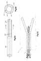
- FIG. 1Aillustrates a side perspective view of a bone augmentation device in accordance with a preferred embodiment of the present invention
- FIGS. 1B-Cillustrate side perspective views of another preferred embodiment of a bone augmentation device in accordance with the present invention
- FIG. 1Dillustrates a cross-sectional view of a bone augmentation device in accordance with an embodiment of the present invention, taken along a longitudinal axis;
- FIG. 2illustrates a cross-sectional view of the bone augmentation device of FIG. 1 , taken along line 2 - 2 of FIG. 1 ;
- FIGS. 3A-Dillustrate side perspective and top plan views, respectively, of a bone augmentation device and its method of use in accordance with a preferred embodiment of the present invention
- FIGS. 4A-Cillustrate side perspective views of a another preferred embodiment of a bone augmentation device in accordance with the present invention.
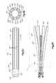
- FIGS. 5A-Cillustrate side perspective views, and an end view taken of FIG. 5A , of a preferred embodiment of a bone augmentation device in accordance with the present invention
- FIGS. 5D-Fillustrate side perspective views, and an end view taken of FIG. 5D , of another embodiment of a bone augmentation device in accordance with the present invention
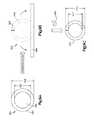
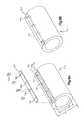
- FIGS. 6A-Cillustrate side perspective views of a bone augmentation device in accordance with a preferred embodiment of the present invention
- FIGS. 7A-Cillustrate cross-sectional views of a bone augmentation device in accordance with a preferred embodiment of the present invention and a preferred insertion instrument in accordance with the present invention
- FIG. 8illustrates a bone augmentation device in accordance with a preferred embodiment of the present invention and a pusher preferred instrument in accordance with the present invention
- FIGS. 9A-Cillustrate steps taken during a first preferred method for forming a bone augmentation device in accordance with the present invention
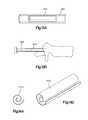
- FIGS. 10A-Eillustrate the steps taken during a second preferred method for forming a bone augmentation device in accordance with the present invention
- FIGS. 11A-Billustrate steps taken during a third preferred method for forming a bone augmentation device in accordance with the present invention
- FIGS. 12A-Fillustrate steps taken during a fourth preferred method for forming a bone augmentation device in accordance with the present invention
- FIGS. 13A-Billustrate steps taken during a first preferred method for implanting a bone augmentation device in accordance with the present invention
- FIGS. 14A-Billustrate front elevational and side perspective views of a bone augmentation device in accordance with another preferred embodiment of the present invention
- FIGS. 15A-Billustrate cross-sectional views of an inserter instrument for use during the implantation of a bone augmentation device in accordance with preferred embodiments of the present invention, such as, for example, the device of FIGS. 14A and 14B ;
- FIG. 16illustrates an alternate, exemplary embodiment of a pedicle screw system in accordance with the present invention
- FIG. 17illustrates an alternative exemplary embodiment of a pedicle screw system in accordance with the present invention
- FIG. 18illustrates a different, exemplary embodiment of a bone screw augmentation system in accordance with the present invention.
- FIGS. 19A-Dillustrate an exemplary embodiment of an insertion instrument in accordance with the present invention.
- Bone implant, bone augmentation device or bone protection device 10in the form of longitudinally elongated member for positioning between shaft of a screw and surrounding bone tissue to increase the holding strength and purchase of the screw is provided.
- the longitudinally elongated memberis dimensioned and configured for insertion into a preformed hole that is to receive the screw, the member having a proximal end, a distal end, and a longitudinal axis.
- the implantin one embodiment may be formed as a strip, preferably a relatively thin strip preferably formed of at least partially demineralized bone, preferably allograft bone tissue that is relatively flexible, elastic and floppy, preferably at least 80% demineralized bone.
- the bone augmentation device 10may be formed of alternative materials, such as, for example, plastics including PEEK, PTU, PET, EVA, PCU or other biocompatible or bioresorbable plastics.
- Other materials for bone augmentation devicemay include metal and metal alloys, such as, for example, stainless steel, titanium or alloys thereof, ceramics and composites or other biocompatible materials now known or hereafter discovered.
- bone plug or bone protection device 10 , 10 ′ for increasing the holding strength or purchase of a bone screw or bone plug or otherwise to protect the substrate, in this example, bonemay be a longitudinally elongated member preferably in the form of a tube or sleeve 20 , 20 ′ including a longitudinal axis 12 , 12 ′, a proximal portion 30 , 30 ′, a distal portion 40 , 40 ′ and a hollow central cavity, passageway or bore 25 , 25 ′.
- a longitudinally elongated memberpreferably in the form of a tube or sleeve 20 , 20 ′ including a longitudinal axis 12 , 12 ′, a proximal portion 30 , 30 ′, a distal portion 40 , 40 ′ and a hollow central cavity, passageway or bore 25 , 25 ′.
- the hollow central cavity or passageway 25 , 25 ′extends completely through the allograft or bone plug 10 , 10 ′ from a distal end 43 , 43 ′ to a proximal end 33 , 33 ′.
- the sleeve 20 , 20 ′may be generally cylindrically shaped but may be other shapes as well.
- the sleeve 20 , 20 ′preferably includes a proximal portion 30 , 30 ′ having a proximal opening 35 , 35 ′ in communication with bore 25 , 25 ′, and a distal portion 40 , 40 ′ having a distal opening 45 , 45 ′ in communication with the bore 25 , 25 ′.
- distal portion 40does not have a distal opening 45 as shown in FIG. 2 , but rather has a closed distal wall 58 , as shown in FIG. 1D .
- the closed distal endcan have a depth 59 , thus the closed distal end can comprise a solid core, which can be advantageous, for example, when inserting the implant into bone, and can aid placement of the bone plug in voids.
- the depth 59 of the solid core forming the closed distal endmay vary, and in one embodiment is preferably between about one tenth of a millimeter (0.1 mm) and about seven millimeters (7 mm), as measured from the distal end 43 , 43 ′ to the bore 25 , 25 ′.
- the depth 59 of the closed endis preferably about seven millimeters (7 mm), and more preferably about three millimeters (3 mm). Other depths of the closed end are contemplated.
- a wall 15 , 15 ′ in the proximal portion 30 , 30 ′is preferably circumferentially continuous without any openings, slots, slits, grooves or perforations therein while the wall 15 , 15 ′ in the distal portion 40 , 40 ′ optionally may contain one or more slots 42 , 42 ′, preferably about three (3) slots arranged concentrically and about one hundred twenty degrees (120°) apart around the circumference of the wall 15 , 15 ′.
- the slots 42 , 42 ′preferably extend through the wall 15 , 15 ′ and communicate with the bore 25 , 25 ′.
- the implantmay include more or less slots 42 ′ including, for example, no slots, or one, two, four, five or more slots. Slots may, for example, allow the radial expansion of the distal portion when used with a bone pin, dowel, or screw.
- the proximal portion 30 , 30 ′may also include slots, or slots 42 , 42 ′ may extend into both the proximal and distal portions 30 , 30 ′, 40 , 40 ′.
- the slots 42 , 42 ′may extend longitudinally for the majority of the length of the distal portion 40 , 40 ′. In the exemplary embodiments of FIGS.
- the slots 42 , 42 ′ in the distal portion 40 , 40 ′may be approximately twenty millimeters (20 mm), more preferably about eighteen millimeters (18 mm) in length.
- the slots 42 , 42 ′may have a width of about one millimeter (1 mm) to about two millimeters (2 mm), more preferably about one and a half millimeters (1.5 mm).
- Other lengths and widths for the optional slots 42 , 42 ′are contemplated.
- the slots 42 , 42 ′may be approximately thirteen millimeters (13 mm) in length.
- the slots 42 , 42 ′do not extend to the distal end 43 , 43 ′ of the distal portion 40 , 40 ′.
- the slots 42 , 42 ′start between about two and about two and a half millimeters (2-2.5 mm), more preferably two and two tenths millimeters (2.2 mm), from the distal end 43 , 43 ′ and extend longitudinally toward the proximal end 33 , 33 ′.
- Other distances of slots 42 , 42 ′ from the distal end 43 , 43 ′are contemplated.
- the slots 42 , 42 ′start between about eight to about eight and a half millimeters (8-8.5 mm), more preferably about eight and two tenths millimeters (8.2 mm), from the distal end 43 , 43 ′.
- Slots 42 , 42 ′preferably have rounded ends 46 , 46 ′, and 48 , 48 ′.
- the wall 15 , 15 ′ of the sleeve 20 , 20 ′may have a thickness 18 , 18 ′ as shown in FIG. 2 that is thinner in the proximal portion 30 , 30 ′ than in the distal portion 40 , 40 ′.
- the wall 15 , 15 ′is between about three tenths of a millimeter (0.3 mm) and about one millimeter (1 mm), more preferably about nine tenths of a millimeter (0.9 mm), thick in the proximal portion 30 , 30 ′, and preferably between about one millimeter (1 mm) and about two millimeters (2 mm), more preferably about one and sixth tenths of a millimeter (1.6 mm), thick in the distal portion 40 , 40 ′.
- Portions of the wall 15 , 15 ′ in distal portion 40 , 40 ′ of the sleeve 20 , 20 ′ as will be described belowmay be thinner than other portions and may have a wall thickness 18 , 18 ′ approximately equal to the wall thickness 18 , 18 ′ in the proximal portion 30 , 30 ′.
- the sleeve 20 , 20 ′may be approximately ten millimeters (10 mm) to about sixty millimeters (60 mm), more preferably about forty millimeters (40 mm) to about forty-five millimeters (45 mm) in length, although other lengths are contemplated depending upon where the augmentation device 10 , 10 ′ is to be utilized.
- An outer diameter 17 , 17 ′ of the sleeve 20 , 20 ′may be substantially uniform and may be about two millimeters (2 mm) to about nine millimeters (9 mm), more preferably in one exemplary embodiment for pedicle screw fixation about six millimeters (6.0 mm) to about six and a half millimeters (6.5 mm), and in separate exemplary embodiments for bone plug applications about five millimeters (5 mm), or about six millimeters (6 mm), or about seven millimeters (7 mm).
- An inner diameter 19 , 19 ′ of the sleeve 20 , 20 ′ in the proximal portion 30 , 30 ′is preferably about four millimeters (4.0 mm) to about seven millimeters (7.0 mm), more preferably about four and two tenths millimeters (4.2 mm) to about five millimeters (5.0 mm), and more preferably about four and four tenths millimeters (4.4 mm).
- the inner diameter 19 , 19 ′ in the proximal portion 30 , 30 ′is contemplated depending, for example, upon the bone screw, bone pin, or bone dowel to be utilized, the opening to be augmented, and the anatomical location of the void being treated.
- the inner diameter 19 , 19 ′ of the proximal portion 30 , 30 ′is preferably smaller than the diameter of the shaft of the bone screw, bone pin, or bone dowel that is intended to be utilized with the implant 10 , 10 ′.
- the inner diameter 19 , 19 ′ of the sleeve 20 , 20 ′ in the distal portion 40 , 40 ′preferably will be smaller than the inner diameter in the proximal portion 30 , 30 ′.
- the inner diameter 19 , 19 ′ of the distal portion 40 , 40 ′is about two and a half millimeters (2.5 mm) to about three and a half millimeters (3.5 mm), more preferably about three millimeters (3.0 mm).
- the implants illustrated and described hereinhave and will be described and may generally be used in connection with pedicle screw fixation or filling bone voids in the spine (for example, in the lumbar, thoracic or cervical regions), those skilled in the art will appreciate that the implant 10 , 10 ′ may be used in other parts of the body such as, for example, long bones, the iliac crest, and bones in the hip, wrist, hand, face, feet, ribs, mandible, extremities, cranium, etc.
- the implantscan be used in long bone applications such as ACL/PCL repair, in which a bone pin or screw may be used to keep the graft in place.
- the implantsmay be used to make the fit between the bone pin or screw and the parent bone stronger.
- the implant 10 , 10 ′ and variations thereofmay be used in other applications, for example as insulators, to provide covering and protection for neural elements and/or vascular structures.
- the length, wall thickness, inner and outer diametersmay be modified to meet the desired criteria of the other parts of the body, or other applications.
- the implants illustrated and described hereinmay be used to anchor and increase the holding strength of bone screws or bone plugs in other tissue including soft tissue and have additional applications where it is desirable to increase the holding strength of screws or plugs, increase their resistance to toggling or act as a protective sheath or guard for a screw or plug to resist breaching.
- the bone augmentation implant 10 , 10 ′preferably is manufactured from bone, more preferably allograft bone.
- the implantis manufactured from cortical bone.
- the allograft bone augmentation implant 10 , 10 ′preferably is at least partially demineralized.
- both the proximal and distal portionsare completely demineralized, for example, but not limited to, at least 80% demineralized.
- the hardness of the implant or bone plugis similar to that of a pencil eraser. It is preferred that the allograft tissue be demineralized in the proximal portion so that the proximal portion of the bone implant is relatively flexible, elastic and floppy.
- the bone tissuemay be demineralized by submerging in a hydrochloric acid bath at a concentration of ⁇ 0.3N for a period of between about half an hour (0.5 hr) to about twenty four hours (24 hr), preferably about six hours (6 hr) to about eight hours (8 hr). Since the extent of demineralization in an acid bath depends upon the shape and thickness of the bone tissue, the time of submersion, the environmental conditions and the concentration of the acid bath, the time of demineralization for particular implants will vary. Where both the proximal and distal portions are completely demineralized, or demineralized to the same extent, the distal portion may be more rigid by having thicker walls 15 , 15 ′ in the distal portion or by other means.
- the additional rigiditypreferably provides resistance to pull out due to wedging of the distal portion between the screw and the vertebrae.
- the proximal portion 30 , 30 ′ of the allograft sleeve 20 , 20 ′is completely demineralized (for example, at least 80% demineralized) and the distal portion 40 , 40 ′ is partially demineralized or nondemineralized, such that the proximal portion 30 , 30 ′ assumes a softer characteristic than the distal portion 40 , 40 ′.
- the implantsare highly demineralized, they can be easily cut into pieces for use in spaces where the voids are smaller than the implant.
- Highly demineralized implantscan be cut along the length of the implant to make sheets appropriate to fill in areas such as the iliac crest, or to reduce stress risers under the anatomical plates used for bony fusions, etc.
- the sheetscan be modified to create tubes of other (smaller) dimensions.
- the implantscan be machined to have a rough outer surface (e.g., ridges, high points, knurl pattern, etc.) in order to increase friction and improve pull-out resistance.
- a rough outer surfacee.g., ridges, high points, knurl pattern, etc.
- the sleeve 20 , 20 ′may be constructed such that both the proximal portion 30 , 30 ′ and distal portion 40 , 40 ′ are formed monolithically from the same single piece of allograft bone tissue.
- the proximal portion 30 , 30 ′may be separately formed from the distal portion 40 , 40 ′ and thereafter coupled together, preferably by allograft bone tissue and without adhesive, although adhesive may be employed.
- the implant or bone plug 10 , 10 ′may be used for pedicle screw applications and may be supplied in different diameters for different size pedicle screws, for example five, six and/or seven millimeter (5, 6 and/or 7 mm) pedicle screws.
- the implant 10 , 10 ′may be between about ten millimeters (10 mm) and about sixty millimeters (60 mm) in length L, preferably approximately forty millimeters (40 mm) in length with an approximately twenty millimeter (20 mm) proximal portion 30 , 30 ′ and an approximately twenty millimeter (20 mm) distal portion 40 , 40 ′.
- the bone augmentation implant 10 , 10 ′is preferably inserted into a pedicle 4 of a vertebra 3 such that the proximal portion 30 , 30 ′ is located in the pedicle region where the bone is primarily cortical bone, and preferably the distal portion 40 , 40 ′ extends into and is located in the vertebral body 5 where the bone is primarily cancellous bone.
- Other lengths of the implant 10 , 10 ′may be utilized, and different proximal and distal length portions may be utilized so that different size vertebrae 3 may be treated.
- the proximal portion 30 , 30 ′is preferably completely demineralized so that it is soft, flexible, elastic and floppy.
- the proximal portion 30 , 30 ′is also preferably thin so that the pedicle screw, upon insertion into and through the proximal portion 30 , 30 ′ presses the sleeve 20 , 20 ′ into the wall of the pedicle 4 to provide increased purchase and anchoring of the bone screw without putting undue stress on the pedicle wall.
- the implantin at least the proximal portion, may act as a protective sheath that may protect neural elements from the screw after a pedicle breach by the pedicle screw.
- the first few threadsbite into the soft allograft bone plug, fixing the proximal portion of the bone plug in the wall of the pedicle 4 .
- any potential motion of the bone plug in the direction of screw insertionis resisted and/or avoided by the initial fixing of the proximal end in the pedicle.
- the bone implant 10 ′includes a protrusion 23 (shown in FIGS. 1B-D and in FIG. 8 ), such as a lip or tab at the proximal end 33 ′.
- the tab or protrusion 23preferably results in an extension, shoulder or flange beyond the outer diameter of the proximal portion 30 ′, such that the tab 23 restricts the implant from rotating and/or translating distally (e.g., into the vertebra 3 ) as the bone screw, bone pin, or other graft is inserted.
- the tab 23may thus serve as a visual aid during placement of the implant, for example to confirm that the implant is not being pushed too deep inside the bone cavity or void.
- the tab 23may assume the form of a full cylindrical section, a partial section or a small tab.
- the tabmay extend a length of about five millimeters (5 mm) away from the proximal end 33 , 33 ′ and may have a thickness of about one to one and a half millimeters (1-1.5 mm), more preferably one and three tenths millimeters (1.3 mm). Other tab lengths and thicknesses are contemplated.
- the tab 23 shown in FIGS. 1B-1Cis provided on sleeve 20 ′.
- the tab 23is manufactured in a straight condition, as shown, for example, in FIG. 1B , as a monolithic extension of the allograft bone tissue of the sleeve 20 ′. Since the material is preferably demineralized allograft bone, the tab 23 is preferably flexible.
- the screw sleeve 20is positioned in the prepared hole and the tab portion 23 is bent ( FIG. 1C ), possibly with a holding sleeve, or forceps, such that the bent tab 23 rests on the outer portion of the pedicle 4 .
- Either a holding sleeve-like instrument, forceps, or an awl-like instrumentmay be used to pin the tab 23 down lightly to the outer wall of the pedicle 4 .
- the pedicle screwis implanted.
- the tab 23preferably resists any inward motion of the sleeve 20 ′ into the pedicle hole as a result of the motion of the screw 7 in that direction.
- the tab 23preferably provides a visual indicator for the surgeon that the allograft or bone plug is correctly positioned in the pedicle 4 and has not moved axially with the screw 7 .
- the distal portion 40 , 40 ′ of the implant 10 , 10 ′is preferably thicker than the proximal portion 30 , 30 ′ so that as the pedicle screw 7 extends into the distal portion 40 , 40 ′, the distal portion 40 , 40 ′ expands in the cancellous portion of the vertebral body 5 to perform a wedging function of the implant 10 , 10 ′ in the bone.
- the pedicle screw 7preferably extends into the distal portion 40 , 40 ′, may extend the length of the distal portion 40 , 40 ′, and may extend out the distal end 43 , 43 ′ of the implant 10 , 10 ′.
- the implantmay be of a length so that the distal portion is located entirely in the pedicle 4 and does not extend into the cancellous portion of the vertebral body 5 .
- the distal portion 40 , 40 ′preferably expands more than the proximal portion 30 , 30 ′, particularly in the cancellous bone, and preferably would expand to a size that is larger than the opening in the pedicle region 4 where the proximal portion 30 , 30 ′ is located to resist the implant 10 , 10 ′ and pedicle screw 7 from pulling out of the vertebra 3 .
- the distal portion 40 , 40 ′may optionally include slots (i.e., material removed from the implant) or slits (i.e., cuts in the wall) to facilitate the expansion of the distal portion 40 to assist in the wedging of the implant into the vertebral bone.
- the slots 42 , 42 ′ or slitsmay extend completely or partially through wall 15 , and may be on the interior or exterior surfaces of the wall 15 , 15 ′.
- the slots or slitsmay take the form of grooves that do not extend through the full thickness of the wall 15 , 15 ′, or perforations or other features in the wall 15 , 15 ′ to increase the flexibility of the implant or implant 10 , 10 ′ and its ability to expand.
- the distal portion 40 , 40 ′undergoes substantially uniform expansion or bulging, and preferably substantially uniform expansion or bulging in the middle of the distal portion.
- the distal end 43 , 43 ′ of the sleeve 20 , 20 ′may be thinner than its adjacent portion, and preferably substantially all the remaining portion of the distal portion 40 , 40 ′. That is, the sleeve wall 15 , 15 ′ is thinned out at the distal end 43 , 43 ′ compared to its adjacent section.
- the distal end 43 , 43 ′has a wall thickness 18 , 18 ′ of between about a half of a millimeter (0.5 mm) and about one millimeter (1 mm), preferably about nine tenths of a millimeter (0.9 mm).
- the distal end section 43 , 43 ′preferably has a wall thickness 18 , 18 ′ about equal to the wall thickness of the proximal portion 30 , 30 ′.
- the distal end section 43 , 43 ′may be approximately three millimeters (3 mm) in length and preferably overlaps, as shown in FIG.
- first and second preferred embodimentsthere is a transition 44 , 44 ′ from the thicker distal portion 40 , 40 ′ to the thinner distal end section 43 , 43 ′, more preferably the wall thickness 18 , 18 ′ transitions at an angle of about forty-five degrees (45°) to about seventy degrees (70°), more preferably about sixty degrees (60°).
- a further transition or internal step 41 , 41 ′ in wall thickness 18 , 18 ′preferably may occur between the thinner proximal portion 30 , 30 ′ and the thicker distal portion 40 , 40 ′, and the wall thickness may transition at about a forty-five degree (45°) to about seventy degree (70°) angle, more preferably about a sixty degree (60°) angle.
- Other angles and locations for the wall thickness transitionare contemplated, as are multiple transitions in wall thickness 18 , 18 ′.
- the sleeve 20 , 20 ′is useful as a bone augmentation device or bone plug 10 , 10 ′, or as part of a system for pedicle screw fixation, particularly for augmenting pedicle screw insertion and anchoring in a vertebra 3 .
- the sleeve 20 , 20 ′is intended to increase the purchase or holding strength of the pedicle screw 7 in the vertebra 3 , and may find particular application in osteoporotic bone.
- the bone augmentation devicemay also be used to avoid the need to use a larger diameter screw in revision surgery, or to improve purchase of the largest diameter screw appropriate for the bone and given surgical procedure.
- an opening or boreis formed in the pedicle 4 of a vertebra 3 that corresponds roughly to the outside diameter of the pedicle screw 7 to be inserted into the vertebra 3 .
- the opening, hole or bore in the bonecan be formed by methods now known or later discovered, such as, for example the use of drill bits, trocars, series of dilators of increasing outer diameter, etc.
- An appropriate sized implant 10is provided and selected for insertion into the opening in the bone.
- the implant 10is selected based upon the size of the pedicle screw 7 to be utilized, and preferably has an inner diameter 19 , 19 ′ in the proximal portion 30 , 30 ′ and distal portion 40 , 40 ′ that is approximately equal to, or less than, the diameter of the shaft of the pedicle screw 7 .
- the implant 10 , 10 ′is also selected to have an appropriate length, and preferably has a length so that the pedicle screw 7 extends into the distal portion 40 , 40 ′ of the sleeve, preferably through the majority of the distal portion 40 , 40 ′ and more preferably through substantially the entire length of the sleeve 20 , 20 ′.
- the length of the sleevepreferably is selected to extend into the vertebral body 5 where the cancellous bone is located, but alternatively the sleeve may be entirely located within the pedicle 4 of the vertebrae.
- the pedicle screw 7may have a forty-millimeter (40 mm) shaft and the sleeve may be approximately forty millimeters (40 mm).
- Other length screws 7 and sleeves 20 , 20 ′are contemplated.
- the selected implant 10 , 10 ′is inserted into the opening formed in the bone so that the proximal end 33 , 33 ′ of the proximal portion 30 , 30 ′ is substantially flush or even with the start of the opening formed in the bone, and the distal portion 40 , 40 ′ is located within the bone and preferably extends into the cancellous region of the vertebral body 5 .
- the pedicle screw 7is inserted into the sleeve 20 , 20 ′ by screwing, i.e., rotating, the screw 7 so that the distal end of the screw 7 extends and travels through the proximal portion 30 of the sleeve 20 , 20 ′.
- the sleeve 20 , 20 ′preferably expands and presses into the wall of the pedicle 4 surrounding the opening in the bone so that an interference fit is formed between the sleeve wall 15 , 15 ′ and the bone.
- the distal end of the pedicle screw 7enters the thicker distal portion 40 , 40 ′ of the sleeve 20 , 20 ′, and expands the distal portion 40 , 40 ′ of the sleeve 20 , 20 ′ preferably into the cancellous bone of the vertebral body 5 .
- the distal portion 40 , 40 ′preferably expands more than the proximal portion 30 , 30 ′, and preferably expands to a larger size than the opening in the proximal portion or pedicle area 4 of the bone, and more preferably creates a wedging effect in the bone, more preferably a bulging effect in the distal portion 40 , 40 ′ that acts as a plug to assist in increasing the holding strength of the bone screw in bone.
- the sleeve 20 , 20 ′preferably does not move axially down the hole in the direction of the screw.
- the distal portion 40 , 40 ′ of the sleeve 20 , 20 ′may sever as it expands so that the distal end section 43 , 43 ′ rips at the distal ends of the slots 42 , 42 ′.
- the area of the distal end section 43 , 43 ′ between the slots 42 , 42 ′ and the opening 45 , 45 ′may rip or tear in a longitudinal manner to permit further expansion of the distal portion 40 , 40 ′ and may preferably separate the distal portion into one or more fingers.
- the thinned section of the distal section 43 , 43 ′preferably facilitates the uniform and symmetric bulging and expansion of the distal portion 40 , 40 ′ and may facilitate ripping of the distal section 43 , 43 ′ between the opening 45 , 45 ′ and the distal end 46 , 46 ′ of one or more of the slots 42 , 42 ′ to create multiple fingers.
- This ripping or breakage of the implant 10 , 10 ′ in the distal end portion 43 , 43 ′ adjacent to multiple slots 42 , 42 ′preferably facilitates the formation of fingers and a more uniform and symmetric bending, bulging and expansion than if the distal section remained as thick as the thicker portions of the distal portion 40 , 40 ′.
- the proximal portion 30optionally may include a plurality of longitudinal slots, slits grooves or perforations (not shown) along the longitudinal axis that terminate just prior to the proximal end 33 , 33 ′ of the sleeve 20 , 20 ′.
- the slots or slitsmay be formed from the external wall surface 13 , 13 ′ of the proximal portion 30 , 30 ′ all the way through to the hollow interior wall 14 , 14 ′ of the proximal portion 30 , 30 ′.
- the slitsalternatively extend radially from the external wall surface 13 , 13 ′ but terminate prior to reaching the hollow interior wall 14 , 14 ′ of the proximal portion 30 , 30 ′.
- the slitsalso may extend from the interior wall 14 , 14 ′ radially toward the exterior wall 13 , 13 ′ but terminate or stop prior to reaching the exterior wall 13 , 13 ′ of the proximal portion 30 , 30 ′.
- the slits or slotsmay also take on the form of perforations that include a series or plurality of punctures that penetrate or partially penetrate the wall 15 , 15 ′ that may be aligned in a pattern or are randomly formed in the wall 15 , 15 ′.
- the implant or bone plug 10 , 10 ′may also be used for bone plug applications, to fill voids in bone, including those in long bones, the iliac crest, and spine, that are prepared or that are left after removal of hardware (e.g., pedicle screws).
- the implantscan be used, for example, to backfill voids created by removal of hardware from load bearing bones, such as heel or ankle bones where bony voids can create stress risers.
- the voidscan be created, for example, using instrumentation such as general surgical dilators and bone tamps, or drills, reamers, awls, dilators, probes, etc.
- pedicle screw 7may be a bone screw, bone pin, bone dowel, or the like.
- the implantis placed in the void, with the proximal tab remaining outside the void.
- the proximal tabis held, using forceps or similar instruments to act as a counterforce to stop rotation or axial motion of the implant with the bone screw, bone pin, or bone dowel, and the bone screw, pin, or dowel is slowly inserted.
- the proximal tabpreferably is held until at least half the length of the bone screw, pin, or dowel is inserted through the implant.
- the bone implants or plugscan be used freeze dried or wet.
- the implantmay be freeze dried or lyophilized.
- the implantIn its freeze dried form, the implant preferably has a smaller outside diameter compared to its fully reconstituted state. Therefore, it can be inserted freeze dried inside a smaller void or cavity than would be accessible by a non-freeze dried implant, and can be allowed to reconstitute with blood, in situ. As the implant reconstitutes, it regains its original dimensions.
- the implantmay appear bent, crooked, small and/or have white coloring on the inside or outside walls; however, the implant will be restored to normal condition after sufficient rehydration.
- the proximal portion of the implantWhen fully rehydrated, the proximal portion of the implant can be stretched radially, to about a 32% increase in diameter, relative to the dry diameter.
- the implantmay, for example, be submerged in a sterile bath of saline. At temperatures of about 100-110° F., the implant may be ready for use in about 5-6 minutes, and fully rehydrated in about 10 minutes or more. Where the saline bath is at temperatures of about 60-70° F., the implant may be ready for use in about 10-12 minutes, and fully rehydrated in about 15 minutes or more.
- the implantmay be considered sufficiently rehydrated if the proximal tab can be bent and an appropriate size instrument (e.g., general surgical dilator and bone tamp) can be inserted into the implant until the instrument tip touches the step inside the implant.
- the implantmay also be considered sufficiently rehydrated if, when pressure is applied to outer diameter of the proximal or distal section of the implant, the inner walls of the implant can be made to touch each other without any damage to the implant.
- the implantcan have multiple holes in its side walls for quick reconstitution. Because the implant is very deformable, it can adjust its dimensions to make a better fit in the cavity or void it is inserted into.
- the closed distal portion of the bone plugcan have a small hole at the distal end, in communication with the bore, to accommodate a guide wire, so that the implant can slide over the guide wire to a desired location.
- This guide wire holepermits the implant to be used in minimally invasive surgical procedures.
- Cannulated dilators, or other instruments such as forceps,may also be used to hold or place the bone plug.
- an instrument with a substantially cylindrical shapesuch as a general surgical dilator
- the dilatorcan be inserted fully or partially into the bore of the implant, and can rest against the implant, such that the implant stays on the dilator without falling off until it is implanted.
- the instrumentcan rest against the closed distal end 43 or the internal step 41 in order to generate the force necessary to overcome any friction.
- the implant and dilatorare thus inserted into the bone void and, once the implant is in position, the dilator is pulled out of the implant, while holding the implant in place, for example, via the proximal ring or tab.
- the implantis thus inserted such that more force is borne by the distal end than the proximal end.
- FIGS. 3A-Dillustrates a different preferred embodiment of a bone augmentation or bone plug device.
- the bone augmentation device 110 of FIG. 3is preferably formed from completely or partially demineralized allograft bone tissue and preferably forms an approximately cylindrical tube or sleeve 120 having a longitudinal axis 112 .
- the bone augmentation device 120has a proximal portion 130 and a distal portion 140 .
- the proximal portion 130preferably is formed of completely demineralized bone (e.g., at least 80% demineralized) and has a hollow cavity or passageway 125 in communication with proximal opening 135 .
- An inside diameter 119 of the hollow portionpreferably is substantially the same as or slightly smaller than the diameter of the bone screw, pin, or dowel intended to be inserted into and through the bone augmentation device 110 .
- the proximal portion 130 and distal portion 140 of the bone augmentation device 110preferably is completely demineralized, (e.g., at least 80% demineralized.
- the proximal portion 130 of the augmentation device 110may be completely demineralized and the distal portion 140 may be partially demineralized or non-demineralized such that the proximal portion 130 is softer and more flexible than the distal portion 140 .
- the proximal portion 130preferably includes a plurality of slits, slots, grooves or perforations 136 , similar to the slits, slots, grooves or perforations 42 , formed along the longitudinal axis 112 that terminate just prior to the proximal end 133 of the implant.
- the implant 110 of FIG. 3is shown with six (6) slits 136 , although more or less slits may be employed as desirable.
- the slits 136may extend partially or entirely through the wall 115 of the implant 110 , although the slits 136 in the preferred embodiment of FIG. 3 extend only partially through the wall 115 from the exterior surface 113 of the sleeve 120 toward the internal wall surface 114 .
- the proximal portion 130may have the wall thickness 18 , outer and inner diameters 17 , 19 and length as described above for the embodiments of FIGS. 1A-D and 2 .
- the total length L 3 of the sleeve 120 , and the lengths of the proximal portion 130 and distal portion 140may have the same lengths as discussed above for the embodiments of FIGS. 1A-D and 2 .
- the distal portion 140 of the allograft implant 110 of the embodiment of FIG. 3is preferably solid and may be flexibly connected to the proximal portion 130 .
- the distal portion 140preferably includes one or more slits 147 that preferably extend all the way from one side of the distal portion to the opposite side of the distal portion.
- two through-slits 147are disposed ninety degrees (90°) apart along the distal portion 140 such that each end of a through slit 147 is disposed ninety degrees (90°) apart from the next through slit 147 to form a cross-hairs pattern. While the distal portion 140 of the embodiment of FIG.
- the distal portion 140may also have a hollow cavity preferably with a cannulation that is smaller in diameter than the cannulation that characterizes the proximal portion 130 .
- the diameter of the cannulation in the distal portion 140may be approximately the same as the diameter of the cannulation in the proximal portion 130 .
- This alternative embodiment having the cannulated distal portionwould be similar to FIGS. 5D-F .
- the interior of the cannulated proximal and/or distal portions 130 , 140may also be demineralized, for example to assist in the bite-in of the pedicle screw 7 .
- the distal end 143 of the implant 110 of the third preferred embodimentmay include a point or blunt end 143 a for ease of insertion.
- the external surface 113 of the proximal and/or distal portion 130 , 140 of the sleeve 120may include surface texturing to improve the grip between the allograft implant 110 and the surrounding bone.
- the distal end of the proximal portion 130may optionally include a beveled edge 131 (see edge 31 in FIG. 1 ) such that an insertion instrument, such as a plunger or push rod, can come to bear against proximal end 133 of the proximal portion 130 during the insertion of the implant 110 into the vertebrae 3 .
- the beveled edge 131can also act as a lead in chamfer 131 to locate the pedicle screw 7 and assist in starting the pedicle screw.
- both the proximal portion 130 and the distal portion 140may be formed monolithically from the same allograft tissue form.
- the proximal and distal portionsalternatively may be machined from separate allograft bone pieces, and thereafter coupled together to permit movement between the pieces, preferably flexibly connected by allograft bone pieces, as will be described in greater detail below. Adhesive may or may not be used as desired to connect the portions together.
- the implant 110is preferably inserted into a preformed hole 2 extending into what may be an osteoporotic vertebral body 5 through a pedicle 4 using an instrument 50 such as a trocar or plunger rod.
- an instrument 50such as a trocar or plunger rod.
- a suitable insertion instrument used in association with the bone augmentation devicesis discussed in detail in reference to FIG. 8 .
- the implant 110preferably is inserted into the bone preferably so that the proximal end 133 is relatively flush and even with the opening 2 in the bone.
- a pedicle screw 7is then preferably inserted into the vertebra 3 through the implant 110 as shown in FIG. 3C .
- the slits 136 disposed along the proximal portion 130 of the allograft sleeve 120spread apart and preferably enable substantially the entire proximal portion 130 to expand radially within the channel in the pedicle 4 , as shown in FIG. 3C , to provide bite into the pedicle 4 through which the proximal portion 130 is disposed.
- the screw threads of the pedicle screw 7preferably deform the softer proximal portion 130 such that threading is formed in the hollow interior wall surface 114 of the proximal portion 130 .
- the distal portion 140splits apart via the slits 147 formed there through as shown in FIG. 3D and presses into the trabecular bone that may be present and forms a wedge between the screw 7 and the posterior wall of the pedicle 4 , providing additional pull out resistance to the pedicle screw 7 .
- the distally expanded distal portion 140 of the allograft sleeve 120 and the radially expanded proximal portion 130 of the sleeve 120preferably improves the purchase of the pedicle screw 7 into the surrounding bone and preferably reduces the likelihood of pedicle screw backout and toggling.
- a biocompatible materialsuch as PMMA, calcium phosphate cement, etc. may be used in conjunction with the allograft implant 110 and pedicle screw 7 placement, such as through the distal end of the pedicle screw, along the distal portion of the implant and/or pedicle screw, or along the entire interior of the implant while still in a liquid state.
- FIGS. 4A-Cshow a further preferred embodiment of bone augmentation device 210 in the form of an allograft tube or sleeve 220 that is preferably completely demineralized (e.g., at least 80% demineralized). While it is preferred that the sleeve 220 be completely demineralized, the sleeve may be partially demineralized, have no demineralization, or have inner and outer surfaces completely or partially demineralized to a different extent than the mid portion of the sleeve 220 .
- completely demineralizede.g., at least 80% demineralized
- the sleevemay be partially demineralized, have no demineralization, or have inner and outer surfaces completely or partially demineralized to a different extent than the mid portion of the sleeve 220 .
- the allograft tube 220preferably includes a longitudinal axis 212 and has a central bore 225 so that the sleeve 220 is hollow throughout its entire length having a proximal and a distal opening 235 , 245 .
- the allograft tube or sleeve 220may further include a tab (not shown) on its proximal end 233 to serve a similar purpose to the tab 23 of the second preferred embodiment.
- the preferably, completely demineralized allograft sleeve 220is preferably inserted into a previously formed hole through a pedicle 4 and into the interior of a vertebral body 5 .
- the allograft sleeve 220is preferably inserted such that the proximal end 233 of the allograft sleeve lies flush with an exterior surface of the pedicle 4 as illustrated for the sleeve 120 in the embodiment of FIGS. 3B-D .
- a pedicle screw 7is preferably inserted though the allograft sleeve 220 and surrounding pedicle and vertebral bone, and as the pedicle screw progresses toward the interior of the vertebral body 5 , the demineralized bone material of the allograft implant 210 is pressed into the pedicle 4 and the interior of the vertebral body 5 , which may be characterized by cancellous bone.
- the demineralized nature of the allograft implantpreferably enhances the osteo-inductive potential of the allograft implant, and the interference fit between the screw, allograft implant and the wall of the pedicle 4 that results from the progression of the pedicle screw 7 through the allograft sleeve 220 increases the pull-out strength of the pedicle screw.
- the allograft sleeve 20may be only partially demineralized on the external and/or internal surface of the allograft sleeve 220 .
- the external surface 213 of the proximal and/or distal portion of the allograft sleeve 220may include surface texturing to improve purchase between the allograft sleeve 220 and the surrounding bone 3 .
- the allograft sleeve 220may include a distal portion 240 that is partially demineralized and a proximal portion 230 that is completely demineralized.
- a pedicle screw 7preferably advances easily in the pedicle 4 owing to the presence of the completely demineralized softer allograft bone in the proximal portion 230 of the allograft sleeve 220 yet provides enough bite to secure its position therein.
- the external surface 213 of the proximal and/or distal portion of the allograft sleeve 220may include surface texturing to improve purchase between the allograft sleeve 220 and the surrounding bone.
- the distal end 243 of the allograft sleevecan be cross-pinned, e.g., with an allograft pin (not shown), to assist in facilitating the insertion of the allograft sleeve.
- Cross pinningwould also improve the visibility of the implant on C-arm.
- the allograft tube or sleeve 220may alternatively include a longitudinal axis 212 and central bore 225 that extends from the proximal opening 235 to the distal opening so the sleeve 220 is hollow throughout its entire length.
- the tube 220may include one or more longitudinal slits, slots, grooves or perforations 247 extending in the direction of the longitudinal axis 212 in the mid-section of the tube 220 .
- the slits 247extend through the tube wall 215 from the exterior surface 213 to the internal wall surface 214 .
- the slits 247preferably do not extend the entire length of the sleeve 220 and preferably do not extend to the distal end 243 or the proximal end 233 .
- a continuous ring section 239is formed at the proximal end 233
- a continuous ring section 251is formed at the distal end 243 .
- the continuous ring sections 239 , 251preferably are about two millimeters (2 mm) to about ten millimeters (10 mm) in length, more preferably about three millimeters (3 mm) to about seven millimeters (7 mm).
- the wall surface 215 at the ring sections 239 , 251preferably is continuous and uninterrupted by the slits 247 .
- the ring sections 239 , 251preferably remain intact upon insertion of the screw.
- the mid-section of the tube 220 containing the slits, or at least a portion thereof,is preferably thicker than the continuous ring sections 239 , 251 .
- the outside diameter 217 of the tube 220is preferably selected to fit within the hole prepared in the bone, while the inside diameter 219 of the tube 220 accepts the screw 7 .
- the inside diameter 219 of the ring sections 239 , 251are preferably larger than the mid-section and preferably should be roughly the same size as the outside diameter of the screw 7 so that the screw 7 can be inserted with relatively little expansion of the ring sections 239 , 251 so that the ring sections 239 , 251 preferably remain intact.
- the inside diameter 219 of the mid-section of the sleeve 220preferably interferes with the screw as the screw is inserted down the sleeve 220 to expand the mid-section as shown in FIG. 4C .
- the screw 7expands and spreads the slits 247 as shown in FIG. 4C .
- the expansion of the mid-sectionimproves the holding strength and purchase of the screw 7 in the bone and preferably resists or prevents toggling of the screw 7 which may cause the screw 7 to shift in the vertebra 3 .
- FIGS. 4A-Chave been shown and described as employing slits 247 that extend through the entire wall thickness from the interior surface 214 to the exterior surface 213 , slits that extend only partially through wall 215 may be used, and the slits 247 may comprise open slots, grooves or perforations.
- tube or sleeve 220has been described as being formed of allograft, and preferably at least partially demineralized allograft
- sleeve 220can be formed of any biocompatible material including metals, metal alloys, ceramics, composites, and plastics, such as, for example, PEEK, PTU, PET, EVA, PCU or other biocompatible or bioresorbable plastics, and the other embodiments of the present application may also be constructed of these different materials.
- FIGS. 5A-Cshow a modification to the designs of the allograft sleeve described in the embodiment of FIG. 4 wherein the distal portion 240 is etched or grooved to weaken the allograft of the distal portion 240 along a parting line 249 , or completely cut into strips, such that the distal portion 240 splits open when the pedicle screw 7 advances through the distal interior of the allograft tube 220 and, thereby, further resists, or prevents pullout.
- the embodiments of FIGS. 4 and 5may be formed monolithically from the same single piece of allograft tissue, or in the alternative may be formed from separate allograft pieces and thereafter coupled together.
- FIGS. 5D-Eshow a further embodiment to the designs of FIG. 4 and FIGS. 5A-C .
- the bone augmentation device 210 ′has a proximal continuous ring section 239 having a wall 215 that defines an opening 235 at the proximal end 233 .
- the opening 233communicates with a hollow cavity 225 .
- a plurality of strips 253extend distally from the wall of the ring section 239 .
- the bone augmentation device 210 ′is preferably monolithic and may be formed from a hollow cylindrical shaped monolithic tube or sleeve that has a continuous cylindrical wall that has a plurality of, in this example, eight, slits 249 cut into the sleeve, all in the distal portion to form thin strips 253 .
- the slits 249may extend into the proximal portion 230 of the sleeve 220 as shown.
- the slits 249preferably extend from the interior wall surface 213 to the exterior wall surface to form uncoupled strips. In the alternative or additionally, the slits 249 may only extend partially through the wall 215 and may tear and detach as the screw progresses down the sleeve 220 .
- FIGS. 6A-Cshow another embodiment of a bone augmentation device 310 , and a method of making the same.
- the bone augmentation device 310preferably is formed from two pieces 360 , 370 and in its assembled form is generally a cylindrically shaped elongated member 320 .
- the elongated member 320preferably includes a relatively thicker and stiffer distal portion or component 340 and a relatively thinner proximal portion or component 330 .
- the distal component 340includes a ring-like proximal end 362 , one or more fingers 364 separated by gaps or space 363 and a connector portion 365 .
- the connector portion 365preferably flexibly connects the fingers 364 to the ring-like proximal end 362 .
- the proximal component 330includes a ring-like connector strip 372 , and one or more extremities 374 , separated by gaps or space 373 .
- the connector strip 372connects the extremities 374 extending from the connector strip 372 .
- Both the proximal component 330 and distal component 340are preferably formed from allograft bone, although other materials are contemplated.
- Preferably both the proximal and distal components 330 , 340are formed of completely or partially demineralized bone, although it may be preferred that the proximal component 330 be completely demineralized while the distal component 340 is only partially demineralized bone, and the distal portion 310 preferably is relatively stiffer than the proximal component 330 .
- the proximal component 330 and the distal component 340are each preferably formed from a single piece of bone and are connected together as discussed below.
- the thickness 318 of the walls 315 of the proximal component 330is less than the thickness 318 of the walls 315 of the distal component 340 .
- the inner diameter 319 of the elongated member 320is preferably slightly smaller than or equal to the outer diameter of the pedicle screw 7 inserted down the hollow channel 325 formed in the sleeve 320 .
- a groove 361separates the fingers 370 from the ring 362 to form the flexible connector portion 365 .
- the width of the groove 361is sufficient in size to fit the width of the connector strip 372 when the components 330 , 340 are joined together as illustrated in FIG. 6C .
- a groove or recessed portion 366is formed in the ring section 360 to accommodate the extremities 374 when the proximal component 330 is assembled to the distal component 340 .
- the fingers 364 of the distal component 340may be pinched together as illustrated in FIG. 6B .
- the connector portion 365acts as a flexible hinge permitting the fingers 364 to move closer together.
- the proximal component 330is inserted and slides over the distal component 340 .
- the fingers 364preferably are inserted down gaps 373 while the extremities 374 correspond to and are slid down the space 363 .
- the distal component 340 and the proximal component 330are urged together so that the fingers 364 extend past the connector strip 372 and the extremities 374 extend past the rigid ring section 362 as shown in FIG. 6C .
- the extremities 374extend and slide through the recesses 366 formed in the ring section 362 .
- the connector strip 372 of the proximal component 330fits within the groove 361 formed in the connector section 365 , and preferably is secured into the distal component 340 .
- the proximal portion 330may be moved relative to and connected to the distal portion 340 without pinching the fingers 364 , if the fingers 364 fit within the gaps 373 and the extremities 374 fit with the gaps 363 .
- the connector portion 365preferably will be sufficiently flexible to permit the connector strip 372 to slide over the arms 364 and fit within the groove 361 .
- the implant 310may include more or less fingers 364 and extremities 374 , and there may be an unequal number of fingers and extremities 364 , 374 .
- the potential advantage of the two-piece bone augmentation device 310is that it can be formed from two shorter pieces of allograft or autograft bone that may be easier to harvest than an appropriate sized single piece of bone.
- a bone augmentation device 410 in accordance with another preferred embodiment in the form of sleeve or tube 420preferably is formed of allograft tissue and preferably includes a longitudinal axis 412 and proximal and distal ends 433 , 443 .
- the sleeve 420preferably also includes a plurality of longitudinal cuts 447 formed in such a way that the proximal end 433 and the distal end 443 of the sleeve 420 remain as continuous rings while the middle portion is formed into thin strips 453 .
- the sleeve 420is preferably partially or completely demineralized subsequent to the formation of the longitudinal cuts 447 .
- the distal portion of the strips 453are preferably formed in such a way that the strips 453 have thin sections 438 at or near their halfway point that preferably serve as flexible hinges 438 a that preferably form a fold line.
- the thinner sections 438 of the strips 453are preferably located at approximately three quarters (3 ⁇ 4) of the length of the hollow tube 420 from the proximal end 433 .
- a pushrod 50is preferably used to insert the hollow sleeve 420 into a pedicle 4 until the proximal end 433 lines up with the outside of the pedicle 4 and a halfway mark on the sleeve 420 lines up against or near the interior of the posterior wall of the vertebral body 5 as shown in FIG. 7B .
- the distal end 443 of the sleeve 420is then preferably pulled back while retaining the proximal end 433 at its position flush with the exterior of the pedicle 4 .
- the distal portion 440folds in half at the hinges 438 as shown in FIG. 7C and, after a certain amount of retraction, locks up into its folded position.
- the pullout strength of the sleeve 420may be thereby improved.
- the distal continuous ring 443may be pulled back toward the proximal portion 430 in a number of different ways.
- the end of the pusher 50may attach to the distal continuous ring 443 and the pusher 50 can be retracted to move the ring 443 proximally.
- the pusher 50can be disengaged from the continuous ring 443 when the ring 443 has been moved proximally so that the hinges 438 have been activated and the distal portion 440 folded and expanded.
- the distal continuous ring 443 of the sleeve 420may alternatively include internal threads (not shown). The internal threads may interact with threading on the distal end of the pusher 50 to connect the pusher 50 to the distal continuous ring 443 .
- the pusher 50is then pulled proximally to retract the distal end 443 toward the proximal end 433 of the sleeve 420 .
- the distal portion 440folds at the hinges 438 and expands in the distal portion 440 to provide better purchase in the vertebra 3 .
- the pusher 50can then be disconnected from the sleeve 420 .
- a threaded rodmay be used to deploy the expandable distal portion 440 by interacting with the threads on the continuous ring 443 . The threaded rod can be rotated to move the ring 443 proximally along the length of the threaded rod.
- the threading on the distal continuous ring 443may interact with the threads on the pedicle screw inserted into the sleeve 420 to retract and move the distal portion 440 to its expanded position as the pedicle screw is rotated into position.
- a separate nut(not shown) may be provided at the distal end of the sleeve 420 to work in conjunction with a threaded rod or pedicle screw 7 to deploy the expandable distal portion 440 .
- FIG. 8shows an insertion instrument that is suitable for use with the implants, and particularly the implant embodiments of FIGS. 1-7 .
- the insertion instrumentserves to implement a simple push or plunge function to the bone augmentation device 10 , 10 ′, 110 , 210 , 210 ′, 310 , 410 , via the pusher element 50 .
- the pusher element 50preferably includes a stop 52 that comes to rest on the posterior wall of the pedicle 4 that serves to limit the length of the implant 10 inserted into the pedicle 4 and vertebral body 5 .
- the insertion instrumentis preferably radiolucent so as to enable the correct positioning of the implant, allograft sleeve, tube, elongated member or shim 10 , 10 ′, 110 , 210 , 210 ′, 310 , 410 .
- FIGS. 1-7have been generally shown and described as cylindrical, it can be readily appreciated that the outer shape, and inner bore shape can take other forms and is not limited to the cylindrical shape shown and described.
- the allograft tissue forms of the present inventionmay be used in a freeze-dried state during implantation and then allowed to rehydrate in situ, or during the implant procedure.
- Backward teeth, ridges, reverse buttresses, threads, one or more keels or other surface texturecan be applied to the exterior surface of the implants 10 , 10 ′, 110 , 210 , 210 ′ 310 , 410 to increase bite into the surrounding bone.
- Completely or partially demineralized allograft bone sticks(not shown), similar in shape and size to toothpicks, or match sticks, can be used as shims between pedicle screws 7 and the surrounding bone into which the pedicle screws 7 are inserted.
- the orientation, location, depth and length of the slits, slots, grooves, cuts or perforations in the plugs or shimscan be configured such that the amount of and location of expansion can be controlled, for example, expansion of the distal portion can occur in a preferred plane.
- Radiographic markers(not shown) can be added to the implants, to help identify the orientation of the implants or portions thereof within the pedicle 4 and/or vertebral body 5 .
- the implantsare not limited to allograft bone construction and may include material compositions other than or in addition to allograft bone, such as any other suitable biocompatible material now or hereafter known including, but not limited to, plastics (e.g., PEEK, PTU, PET, EVA, PCU or other biocompatible or bioresorbable plastics), thermoplastics, rubber, titanium, stainless steel, titanium alloy, metal alloys, ceramic, etc.
- plasticse.g., PEEK, PTU, PET, EVA, PCU or other biocompatible or bioresorbable plastics
- thermoplasticsrubber, titanium, stainless steel, titanium alloy, metal alloys, ceramic, etc.
- FIGS. 9A-Ca method of forming an allograft tube 520 in accordance with one preferred embodiment that includes having smaller outer and inner diameters 517 , 519 than the outer and inner diameters 587 , 589 of the original donor bone, and an implant 510 resulting from the method is shown.
- FIG. 9Aincludes a donor bone 580 , such as a tibia or femur, having an outer diameter 587 and an intramedullary canal 584 defining an inner diameter 589 .
- a cut 583is made in the donor bone 580 , the donor bone 580 is demineralized and thereafter unrolled resulting in a sheet 585 as shown in FIG. 9B .
- the sheet 585may be trimmed to a desired length and width. Thereafter, the sheet 585 may be rolled up to form a tube or sleeve 520 as shown in FIG. 9C having an outer diameter 517 and an inner diameter 519 . Electromagnetic radiation 590 may be applied to the demineralized bone to form a weld between the two ends of the sheet 585 in order to weld the ends of the sheet 585 together to form hollow tube 520 .
- the allograft tube 520is at least partially demineralized and is configured to provide enhanced purchase between a pedicle screw and a hole into the interior of a vertebral body 5 , as well as enhance osteointegration of the tube 520 within the vertebra 3 .
- the two ends of the sheet 585may also be compressed together and subjected to demineralization bath to secure or weld the ends together.
- the donor bone 580preferably is completely demineralized such that the sheet 585 can be produced by forming the cut 583 and unrolling the donor bone 580 to form the sheet or planar structure 585 .
- the sheet 585is then trimmed to a desired length and width from which the desired characteristics, including circumference, inner diameter 519 , and outer diameter 517 , and length L, of the allograft tube 520 is be provided. Slits, slots, grooves, perforations, and differences in wall thickness can also be formed and manufactured in the sheet 585 .
- the sheet 585is then rolled back into a tubular form and electromagnetic radiation 590 , e.g., from an Nd—YAG laser (Neodymium-doped Yttrium Aluminum Garnet) is applied to the area 591 where the ends abut to form a weld, resulting in the allograft tube 520 .
- electromagnetic radiation 590e.g., from an Nd—YAG laser (Neodymium-doped Yttrium Aluminum Garnet) is applied to the area 591 where the ends abut to form a weld, resulting in the allograft tube 520 .
- the allograft tube 520can be inserted into a hole through a pedicle 4 and into the interior of a vertebral body 5 , such that the proximal end 530 of the allograft tube 520 lies flush with the exterior surface of the pedicle 4 .
- a pedicle screw 7is inserted though the allograft tube 50 and surrounding pedicle 4 and vertebral bone and, as the pedicle screw 7 progresses toward the interior of the vertebral body 5 , the demineralized bone material of the allograft tube 520 is pressed into the pedicle 4 and the interior of the vertebral body 5 , which may be characterized by cancellous bone.
- the demineralized nature of the allograft tube 520enhances the osteo-inductive potential of the allograft tube 520 and the pressed material that results from the progression of the pedicle screw through the allograft tube 520 increases the pull-out strength of the pedicle screw 7 .
- FIG. 10A-Eillustrate an alternate method of forming an allograft tube 620 that is similar to the allograft tube 520 . All elements described in reference to FIG. 10A-E are similar to those described in FIG. 9A-C , with the exception of a female dovetail 637 , a male dovetail 657 , and a joint 659 formed from the female and male dovetails 637 , 657 .
- the allograft tube 620is formed from a donor bone 682 wherein the outer and inner diameters 617 , 619 of the allograft tube 620 are smaller than the outer and inner diameters 687 , 689 of the donor bone 682 .
- the donor bone 682is demineralized, cut, and unrolled into a flat sheet 685 .
- the sheet 685is trimmed to the desired dimensions and one or more female and male dovetails 637 , 657 are cut into the edges of the sheet 685 .
- the sheet 685is then rolled into a cylindrical form and the female and male dovetails 637 , 657 are mated together to form the joints 659 , and thereby secure the allograft tube 620 together. Additionally, biocompatible adhesive and/or electromagnetic radiation can be used to further enhance the strength of joint 659 . Further the joints 659 may be subjected to a demineralization acid or fluid to secure or weld the joints 659 together.
- FIGS. 11A-Billustrate a method 700 for forming an allograft tube 720 in accordance with a further preferred embodiment that has smaller outer and inner diameters 717 , 719 than the original donor bone 782 .
- the allograft tube 720forms a bone plug implant 710 .
- Tabs 722 and 724are preferably formed on alternate sides of a slot 726 formed through the donor bone 782 .
- a slab 727 having a plurality of holes 728 and generally formed as a rectangular piece of demineralized allograft boneis configured to be received into the slot 726 .
- a plurality of dowel pins 775are configured to be received through the matching holes 728 , 721 as shown in FIG. 11B .
- an allograft tube 720is formed from a donor bone 782 wherein the outer and inner diameters 717 , 719 of the allograft tube are smaller than the outer and inner diameters 787 , 789 of the donor bone 782 .
- the donor bone 782is cut along its length to form the slot 726 and tabs 722 , 724 .
- the holes 721are drilled into the tabs 722 , 724 .
- the donor bone 782is then demineralized.
- the tabs 722 , 724 and, optionally, the holes 721are masked during the demineralization process to retain their rigidity.
- Another piece of demineralized allograft boneis then cut into a rectangular form to produce the slab 727 and a plurality of holes 728 are drilled through the slab 727 .
- the slab 727 and the holes 728are configured to mate with the tabs 722 , 724 and the holes 721 formed on the donor bone 782 .
- Appropriate sized dowel pins 775are cut from bone and the allograft tube 720 is assembled together by mating the slab 727 to the tabs 722 , 724 and aligning the plurality of holes 721 with the plurality of holes 728 .
- the plurality of pins 775are then inserted through the plurality of holes 721 , 728 .
- the allograft tube 720can be demineralized again to fuse the connections formed between the slot 726 and the slab 727 , as well as between the pins 775 and the holes 721 , 728 .
- FIGS. 12A-Fillustrate a method 800 for forming an allograft tube 820 in accordance with another preferred embodiment that has smaller outer and inner diameters 817 , 819 than the original donor bone 882 .
- the tube 820results in an implant 810 for preferably increasing the holding strength and purchase of a bone screw.
- Mating tabs 822 , 824preferably are formed on alternate sides of the sheet 885 which was formed by cutting, unrolling and trimming the donor bone 882 .
- a plurality of holes 821are formed through the tabs 822 , 824 as shown in FIGS. 12C-D .
- a plurality of dowel pins 875are configured to be received through the holes 821 .
- the pins 875include a plurality of right angles, such as a capital “I” shape or “Z” shape, with the corners of the “Z” shape preferably formed at right angles as opposed to oblique angles.
- the pins 875are formed from bone and the right angle portions included therein are demineralized to the point of flexibility such that a plurality of hinges 876 , 877 are formed at the right angle portions such that the pins 875 can be flexed at their hinges 876 , 877 into a straight configuration during insertion through the straight holes 821 and spring back into their original “I” or “Z” shape subsequent to being inserted through the holes 821 .
- the allograft tube 820is formed from a donor bone 882 wherein the outer and inner diameters 817 , 819 of the allograft tube 820 are smaller than the outer and inner diameters 887 , 889 of the donor bone 882 .
- the donor bone 882is demineralized, cut, and unrolled into a flat sheet 885 .
- the sheet 885is trimmed to the desired dimensions, mating tabs 822 , 824 are cut, and the holes 821 are drilled through the tabs 822 , 824 to form the sheet 886 .
- the sheet 886is then rolled into a cylindrical form and the tabs 822 , 824 are overlapped such that the holes 821 through both of the tabs 822 , 824 are aligned.
- the flexible hinges 876 and 877straighten out temporarily and spring back to their initial configuration upon being positioned appropriately with respect to the holes 821 , i.e., the longer shaft portion 878 of the pins 756 are inside and traverse the holes 821 and the top and bottom transverse portions 881 , 882 protrude and lie transversely atop holes 821 .
- the allograft tube 820has smaller outer and inner diameters 817 , 819 than the outer and inner diameters 887 , 889 which characterize the original donor bone 882 .
- FIGS. 13A-Billustrate an allograft tube 920 in accordance with another preferred embodiment that may be identical or similar to any of the allograft tubes 520 , 620 , 720 , or 820 described above or, alternately, may result from a donor bone 982 that is demineralized, sliced open, flattened into a sheet, cut to the desired dimensions, and re-rolled into a tubular form that does not include any mechanical securement mechanisms, such as the weld resulting from the application of radiation 590 , the dovetail joint 659 , the slab 727 and pins 775 , or the holes 821 and pins 875 .
- any mechanical securement mechanismssuch as the weld resulting from the application of radiation 590 , the dovetail joint 659 , the slab 727 and pins 775 , or the holes 821 and pins 875 .
- the donor bone 982may be formed into a relatively flat sheet of a desired length, for example forty millimeters (40 mm), and a desired thickness, for example, about half a millimeter (0.5 mm) to about two millimeters (2 mm), preferably about seventy five hundredths of a millimeter (0.75 mm).
- the sheetmay be supplied to the surgeon as a sheet and may be demineralized and/or freeze dried and the surgeon can cut the sheet to a desired width, during the surgery or just prior to surgery, depending upon the diameter of the hole and the diameter of the implant.
- the surgeoncan roll the sheet into tubular form and insert it into the hole.
- the screwmay thereafter be inserted into the hole in the bone with the sheet material in rolled or strip form preferably increasing the purchase and holding strength of the screw.
- the preferred methodfurther includes a tube 955 that can be formed from metal or plastic and into which allograft tube 920 is inserted.
- the allograft tube 920may be formed as described above and inserted into the tube 955 .
- the allograft tube 920may be freeze dried while inside the tube 955 , or may be freeze dried and then inserted in the tube 955 .
- the freeze-dried allograft tube 920preferably remains inside the tube 955 during packaging and shipping.
- the implant 920may be inserted in the tube 955 prior to or during surgery.
- the tube 955is then aligned with a preformed pilot hole in a pedicle 4 of the vertebral body 5 and the plunger 950 or a push rod is advanced with respect to the tube 955 to push the allograft tube 920 into the pedicle to serve as an augmentation or guard device or, in an alternate embodiment, into the interior of the vertebral body 5 to serve as a vertebral body augmentation filler.
- the allograft tube 920undergoes in situ rehydration upon coming into contact with blood and other biomaterial, thereby expanding to fit securely within the hole formed through the pedicle.
- the tube 955may be inserted into the hole, which is to receive the screw.
- a push rod 950is placed in the tube and may abut the proximal end of the implant.
- the tube 955is thereafter withdrawn over the push rod 950 so that the implant 920 remains in position in the hole.
- the implantmay then rehydrate upon coming into contact with blood and other biomaterial. This alternative method may better protect the implant during the insertion procedure, particularly protect the more fragile, flexible or floppy implants so that they are properly positioned and remain intact.
- FIGS. 14A-Billustrate an allograft tube 1020 in accordance with another preferred embodiment that is formed in a manner similar to the allograft tube 920 , except that it is rolled helically to form a spiral tubular structure, as opposed to the cylindrical allograft tubes 920 .
- the allograft tube 1020upon freeze drying, preferably is characterized by an outer diameter that is smaller than its outer diameter upon rehydration and smaller than the diameter of the pedicle hole into which it is intended to be implanted. As such, the allograft tube 1020 is configured to fit a variety of hole sizes formed into a pedicle 4 and the yield of the implant formed from the available donor tissue 1082 is enhanced.
- the use of freeze dried allograft tube 1020further avoids interference experienced during its insertion into a pedicle hole by avoiding contact with any irregularities in the wall of the pedicle due to its reduced pre-rehydration diameter.
- the allograft tubeis helically wound and freeze-dried.
- the allograft tube 1020is then manually inserted into a hole formed in a pedicle 4 and, upon contact with blood and other biomaterial inherent to the interior of the pedicle 4 , rehydrates and expands, preferably fitting snugly within the hole to provide a pedicle augmentation device or guard, as described above, for subsequent pedicle screw 7 insertion.
- the helically wound implant 1020may be inserted using the method and instruments described above for FIG. 13 , or using the inserter instrument described in FIG. 8 .
- Inserter 1091useful for the insertion of the allograft tube 1020 is provided.
- the inserter 1091may also be used to insert the implants of FIGS. 1-12 .
- Inserter 1091includes an inner shaft 1092 having a spreading cone 1093 at its distal end 1094 .
- the inner shaft 1092is coupled to a cannulated outer sleeve 1095 via one or more pins 1096 extending transversely from the inner shaft 1092 and through the outer sleeve 1095 .
- the one or more pins 1096may be welded to, screwed to, or otherwise securely coupled to the inner shaft 1092 and outer sleeve 1095 .
- the outer sleeve 1095further includes an opening 1097 at its distal end 972 .
- the inserter 1091further includes a plunger 1099 that includes a hollow distal portion 1100 configured to mate with the inner shaft 1092 .
- the plunger 1099moves axially, along the longitudinal axis of the inserter 1091 , relative to the inner shaft 1092 and the outer sleeve 1095 .
- the plunger 1099includes one or more slots 1068 configured to slidingly receive there through the one or more pins 1096 .
- the number of slots 1068 disposed through the plunger 1099preferably corresponds to the number of pins 1096 included in the inserter 1091 .
- the one or more pins 1096are configured to prevent overextension of the plunger 1099 with respect to the inner shaft 1092 and, as a result, prevent over insertion of the allograft tube 920 into the pedicle hole, as well as to maintain the distal end of the spreader cone 1093 aligned with the distal end 1098 of the outer sleeve 1095 .
- the helically wound, freeze dried allograft tube 920 , 1020is loaded into and stored within the inserter 1091 concentrically around the inner shaft 1092 . Any of the other implants described herein as well as other implants, alternatively and additionally may be loaded into and inserted using inserter 1091 .
- the allograft tube 920 , 1020may be rehydrated while inside the inserter 1091 using a rehydrating agent such as saline. The distal end of the inserter 1091 is placed adjacent to the vertebral body 5 (as shown in FIG.
- the plunger 1099is advanced with respect to the outer sleeve 1095 and the inner shaft 1092 , and guided via the interaction of the one or more pins 1096 with the corresponding one or more slots 1068 .
- the distal end of the plunger 1099engages the proximal end 933 of the allograft tube 920 and causes the allograft tube 920 to advance within and out the distal end of the inserter 1091 .
- the allograft tube 920advances distally along the inner shaft 1092 , the allograft tube 920 advances over the spreader cone 1093 , causing the allograft tube 920 to radially expand (e.g., unwind), just prior to implantation into the hole formed in the pedicle 4 .
- the spreader cone 1093may or may not expand the implant.
- the one or more pins 1096engage the terminal ends of the one or more slots 1068 upon optimal advancement of the allograft tube 920 with respect to the pedicle hole to prevent over insertion of the allograft tube 920 .
- the inserter 1091may be utilized in a different method.
- the implantis loaded within the inserter and around the inner shaft 1092 and the distal end of the inserter 1091 is inserted into the hole prepared in the bone where the bone augmentation device is to be inserted.
- the plunger 1099is advanced with respect to the outer sleeve 1095 so that it engages the proximal end of the implant.
- the plunger 1099is moved with respect to the outer sleeve 1095 to retract the outer sleeve 1095 and spreader cone 1093 out of the bone while the implant remains within the bone and in the hole as the inserter 1091 is withdrawn from the bone.
- a relatively small diameter instrument 1091 with a compacted bone augmentation devicemay be inserted into a relatively small hole to receive a bone screw, the inserter 1091 is operated to pull back the outer sleeve 1095 and the bone augmentation device is expanded and deployed in the bone in a larger size than its inserted size.
- a pedicle screw 7 that is inserted into a vertebral body 5 through a pedicle 4preferably includes one or more radial holes 8 through the minor axis of the pedicle screw's shaft that can be radiographically visualized intraoperatively.
- These radial holes 8when positioned at an appropriate orientation, may serve as guides to drill a cross hole through the pedicle 4 subsequent to insertion of the pedicle screw such that the cross holes formed in the pedicle 4 and the radial holes 8 of the pedicle screw 7 line up.
- a strip of allograft bone 29is preferably used in conjunction with the radial holes 8 of the pedicle screw 7 that preferably includes two demineralized opposite end portions that are flexible and a short, stronger, partially demineralized middle portion.
- the allograft strip 29is preferably inserted through the cross holes of the pedicle 4 and the radial holes 8 of the pedicle screw such that the stronger middle portion of the allograft strip 29 sits as a pin within the radial holes 8 of the pedicle screw.
- a knotcan be tied around the posterior elements of the vertebra using the flexible opposite end portions of the allograft strip 29 and thus securing the pedicle screw with respect to the vertebra 3 .
- the entire length of the allograft strip 29can be completely demineralized and an eyelet type device (not shown) formed of biocompatible material may be secured around the middle portion of the allograft strip 29 to serve as a barrier or grommet between the allograft strip 29 and the radial hole 8 of the pedicle screw shaft to lend structural strength to and protect the portion of the allograft strip 29 that contacts the radial holes 8 of the pedicle screw 7 .
- Holescan alternatively be formed into the lamina at an appropriate angle and with appropriate care not to damage the adjacent neural elements or blood vessels, and the allograft strip 29 may be threaded through the radial holes 8 of the pedicle screw 7 and through or into the holes formed in the lamina.
- Suture threads or metal wire, e.g. titanium wire, etc.also can be used in place of the demineralized allograft strip 29 .
- a pedicle screw 7that preferably includes a cannulated portion 9 extending from the proximal end of the pedicle screw 7 and terminating at one or more radial cut outs or slots 11 located at or near the midpoint along the pedicle screw's longitudinal axis.
- the slots 11extend from the exterior of the pedicle screw to the interior cannulation.
- One or more partially or fully demineralized bone strips 56may be fed from the proximal end 6 , down the cannulation 9 , and partially out the radial cut outs 11 using a simple instrument such as, for example, a plunger rod 50 .
- the one or more radial slots 11may be disposed at or near the distal end of the pedicle screw 7 and the cannulated interior portion 9 may extend from the proximal end 6 and terminate at the radial slots 11 .
- the radical slotsmay be provided at other locations along the shaft of the pedicle screw.
- Allograft bone strips 56may be fed down the cannulation 9 and partially out the distal radial cut outs 11 . As the pedicle screw 7 is advanced into bone, the allograft strips 56 are pulled out the distal radial slots 11 such that the crushed allograft bone surrounds the threaded shaft from the distal end to the proximal end.
- a flowable materialmay be injected into the threads of the screw 7 with a coupling mechanism that drives the screw 7 into the pedicle.
- a cannulated pedicle screw 7preferably includes one or more radial slots 11 disposed at the end of the cannulation and/or somewhere between the distal end and the midpoint of the pedicle screw 7 .
- the pedicle screw 7is preferably fully inserted into a vertebral body 5 through the pedicle 4 and one or more partially demineralized allograft strips 56 are placed into the cannulated interior of the pedicle screw.
- a pusher rod 50 or other instrumentis preferably placed at the proximal end 6 of the pedicle screw 7 and made to bear against the proximal end of the allograft strip 56 such that the distal end of the allograft bone strip 56 advances out of the radial cut out 11 preferably at an angle to the longitudinal axis of the screw 7 , providing anchorage for the screw 7 into the cancellous interior of the vertebral body 3 .
- the proximal end of the pedicle screw 7is then preferably sealed with a plug formed of biocompatible material such as, for example, bone, stainless steel, or titanium, to prevent the one or more allograft strips 56 from backing out of the pedicle screw 7 .
- a pedicle screw 1207 in accordance with another embodimentincludes a proximal portion 1205 , a distal portion 1206 and a cannulated interior 1209 that extends through the proximal portion 1205 and at least partially into the distal portion 1206 .
- a hinge mechanism 1211preferably connects the distal portion 1206 and the proximal portion 1205 at or near the half way point along the longitudinal axis.
- the distal portion 1206preferably includes slots 1242 along the longitudinal axis and into the cannulated interior 1209 such that a plurality, e.g., four, legs 1216 , are formed and connected to one another using the flexible hinge mechanism 1211 .
- Threadingis preferably machined onto the external surfaces of the shaft of the screw 1207 .
- a first stateas shown in FIG. 19C , the four legs assume a closed position such that the distal portion 1206 is similar to a standard pedicle screw shaft.
- a compressed coil spring 1201is preferably inserted under pressure into a long, hollow tube 1202 .
- the coil spring 1201is compressed and would expand if the tube 1202 did not hold the spring 1201 in its compressed state.
- the tube 1202is preferably inserted into the cannulated interior 1209 of the pedicle screw 1207 such that the spring 1201 is located at or near the distal end 1206 of the pedicle screw 1207 .
- the pedicle screw 1207is then preferably inserted into a vertebra 3 through a pedicle 4 .
- a push rod 1203 as shown in FIG. 19Cis preferably placed against the proximal end of the spring 1201 to hold the spring 1201 in position in the distal portion 1206 of the screw 1207 as the tube 1202 is withdrawn from the screw 1207 .
- As the tube 1202 is retracted from the spring 1201as shown in FIG.
- the spring 1201which is held in the compressed state in the tube 1202 , is no longer contained within the tube 1202 so the spring 1201 unwinds and pushes open the legs 1216 such that the distal portion 1206 is expanded preferably into the cancellous interior of the vertebra 3 and the pull-out strength of the pedicle screw 1207 is increased.
- the pedicle screw 1207is illustrated with two hinge mechanisms 1211 , 1212 as shown in FIG. 19D , although other hinge mechanisms and configurations are contemplated.
- the bone augmentation screw 1207has been shown as having four legs 1216 , more or less legs 1216 may be utilized.
Landscapes
- Health & Medical Sciences (AREA)
- Orthopedic Medicine & Surgery (AREA)
- Life Sciences & Earth Sciences (AREA)
- Surgery (AREA)
- General Health & Medical Sciences (AREA)
- Neurology (AREA)
- Veterinary Medicine (AREA)
- Engineering & Computer Science (AREA)
- Biomedical Technology (AREA)
- Heart & Thoracic Surgery (AREA)
- Public Health (AREA)
- Animal Behavior & Ethology (AREA)
- Molecular Biology (AREA)
- Medical Informatics (AREA)
- Nuclear Medicine, Radiotherapy & Molecular Imaging (AREA)
- Cardiology (AREA)
- Oral & Maxillofacial Surgery (AREA)
- Transplantation (AREA)
- Vascular Medicine (AREA)
- Prostheses (AREA)
- Surgical Instruments (AREA)
- Dowels (AREA)
Abstract
Description
Claims (53)
Priority Applications (1)
| Application Number | Priority Date | Filing Date | Title |
|---|---|---|---|
| US12/945,156US8840677B2 (en) | 2008-06-19 | 2010-11-12 | Allograft bone plugs, systems and techniques |
Applications Claiming Priority (4)
| Application Number | Priority Date | Filing Date | Title |
|---|---|---|---|
| US7399808P | 2008-06-19 | 2008-06-19 | |
| US10686208P | 2008-10-20 | 2008-10-20 | |
| PCT/US2009/048055WO2009155577A2 (en) | 2008-06-19 | 2009-06-19 | Bone screw purchase augmentation implants, systems and techniques |
| US12/945,156US8840677B2 (en) | 2008-06-19 | 2010-11-12 | Allograft bone plugs, systems and techniques |
Related Parent Applications (1)
| Application Number | Title | Priority Date | Filing Date |
|---|---|---|---|
| PCT/US2009/048055Continuation-In-PartWO2009155577A2 (en) | 2008-06-19 | 2009-06-19 | Bone screw purchase augmentation implants, systems and techniques |
Publications (2)
| Publication Number | Publication Date |
|---|---|
| US20110144766A1 US20110144766A1 (en) | 2011-06-16 |
| US8840677B2true US8840677B2 (en) | 2014-09-23 |
Family
ID=40974386
Family Applications (1)
| Application Number | Title | Priority Date | Filing Date |
|---|---|---|---|
| US12/945,156Active2030-01-05US8840677B2 (en) | 2008-06-19 | 2010-11-12 | Allograft bone plugs, systems and techniques |
Country Status (8)
| Country | Link |
|---|---|
| US (1) | US8840677B2 (en) |
| EP (1) | EP2355721A2 (en) |
| JP (1) | JP2011525229A (en) |
| KR (1) | KR20110033199A (en) |
| CN (1) | CN102119007A (en) |
| BR (1) | BRPI0914950A2 (en) |
| CA (1) | CA2728312A1 (en) |
| WO (1) | WO2009155577A2 (en) |
Cited By (19)
| Publication number | Priority date | Publication date | Assignee | Title |
|---|---|---|---|---|
| US20140214088A1 (en)* | 2011-02-14 | 2014-07-31 | Glenn R. Buttermann | Orthopaedic plate |
| US20140350608A1 (en)* | 2012-01-31 | 2014-11-27 | The University Of Toledo | Bioactive Fusion Device |
| US20150374503A1 (en)* | 2014-06-30 | 2015-12-31 | Bacterin International, Inc. | Implant for fusion between adjacent bone bodies |
| US9474561B2 (en) | 2013-11-19 | 2016-10-25 | Wright Medical Technology, Inc. | Two-wire technique for installing hammertoe implant |
| US9498273B2 (en) | 2010-06-02 | 2016-11-22 | Wright Medical Technology, Inc. | Orthopedic implant kit |
| US9498266B2 (en) | 2014-02-12 | 2016-11-22 | Wright Medical Technology, Inc. | Intramedullary implant, system, and method for inserting an implant into a bone |
| US9504582B2 (en) | 2012-12-31 | 2016-11-29 | Wright Medical Technology, Inc. | Ball and socket implants for correction of hammer toes and claw toes |
| US9545274B2 (en)* | 2014-02-12 | 2017-01-17 | Wright Medical Technology, Inc. | Intramedullary implant, system, and method for inserting an implant into a bone |
| US9603643B2 (en) | 2010-06-02 | 2017-03-28 | Wright Medical Technology, Inc. | Hammer toe implant with expansion portion for retrograde approach |
| US20170100172A1 (en)* | 2011-12-12 | 2017-04-13 | Wright Medical Technology, Inc. | Fusion implant |
| US9724140B2 (en) | 2010-06-02 | 2017-08-08 | Wright Medical Technology, Inc. | Tapered, cylindrical cruciform hammer toe implant and method |
| US9724139B2 (en) | 2013-10-01 | 2017-08-08 | Wright Medical Technology, Inc. | Hammer toe implant and method |
| US9743961B2 (en) | 2013-06-24 | 2017-08-29 | The University Of Toledo | Bioactive fusion device |
| US9808296B2 (en) | 2014-09-18 | 2017-11-07 | Wright Medical Technology, Inc. | Hammertoe implant and instrument |
| US10080597B2 (en) | 2014-12-19 | 2018-09-25 | Wright Medical Technology, Inc. | Intramedullary anchor for interphalangeal arthrodesis |
| US10555758B2 (en) | 2015-08-05 | 2020-02-11 | Woven Orthopedic Technologies, Llc | Tapping devices, systems and methods for use in bone tissue |
| US10588677B2 (en) | 2014-08-05 | 2020-03-17 | Woven Orthopedic Technologies, Llc | Woven retention devices, systems and methods |
| US11395681B2 (en) | 2016-12-09 | 2022-07-26 | Woven Orthopedic Technologies, Llc | Retention devices, lattices and related systems and methods |
| EP4267023A4 (en)* | 2020-12-28 | 2024-10-30 | University of Maryland Medical System Corporation | BONE SCREW WITH REVERSE THREAD |
Families Citing this family (52)
| Publication number | Priority date | Publication date | Assignee | Title |
|---|---|---|---|---|
| WO2009155121A2 (en) | 2008-05-30 | 2009-12-23 | Amgen Inc. | Inhibitors of pi3 kinase |
| KR20110033199A (en)* | 2008-06-19 | 2011-03-30 | 신세스 게엠바하 | Bone Screw Percussion Augmented Implants, Systems and Technologies |
| US9364276B2 (en) | 2009-07-09 | 2016-06-14 | Smith & Nephew, Inc | Tissue graft anchor assembly and instrumentation for use therewith |
| CN101912300B (en)* | 2009-09-29 | 2012-08-22 | 张强 | Minimally invasive pedicle screw fixation for thoracolumbar fractures |
| US20110288588A1 (en)* | 2010-05-20 | 2011-11-24 | Spinefrontier Inc | System and method for facet fixation and fusion |
| CN103006312B (en)* | 2010-09-03 | 2017-11-03 | 张强 | Minimally invasive bone fracture screw inserts opener |
| DE102010041226A1 (en) | 2010-09-22 | 2012-03-22 | Aces Gmbh | Bone anchoring device |
| US9687278B2 (en)* | 2011-03-21 | 2017-06-27 | Ronald Childs | Sleeve for bone fixation device |
| US9113972B2 (en) | 2011-08-24 | 2015-08-25 | Pioneer Surgical Technology, Inc. | Apparatus and methods for immobilization and fusion of a synovial joint |
| HK1201138A1 (en)* | 2011-10-10 | 2015-08-28 | William Casey Fox | Shape changing bone implant for enhanced healing |
| ITMI20112361A1 (en)* | 2011-12-22 | 2013-06-23 | Franco Beoni | SURGICAL SCREWS WITH BONE SHIRT |
| CN104271057A (en)* | 2012-03-12 | 2015-01-07 | 维克辛姆公司 | Universal anchor for bone fixation |
| US9283089B2 (en) | 2012-04-05 | 2016-03-15 | Warsaw Orthopedic, Inc. | Interbody bone implant device |
| US9730801B2 (en) | 2012-04-17 | 2017-08-15 | Warsaw Orthopedic, Inc. | Interbody bone implant device |
| US9101606B2 (en) | 2012-04-19 | 2015-08-11 | Warsaw Orthopedic, Inc. | Bone delivery system having a therapeutic agent |
| US9220608B2 (en) | 2012-04-24 | 2015-12-29 | Warsaw Orthopedic, Inc. | Facet joint implant device |
| US8771368B2 (en) | 2012-04-24 | 2014-07-08 | William F. McKay | Interspinous bone implant device |
| US9480567B2 (en) | 2012-05-07 | 2016-11-01 | Warsaw Orthopedic, Inc. | Bone implants and methods comprising demineralized bone material |
| US9585764B2 (en) | 2012-07-26 | 2017-03-07 | Warsaw Orthopedic, Inc. | Bone implant device |
| US20140067069A1 (en) | 2012-08-30 | 2014-03-06 | Interventional Spine, Inc. | Artificial disc |
| US8915947B2 (en)* | 2012-10-18 | 2014-12-23 | Spectrum Spine Ip Holdings, Llc | Surgical access system |
| US10172651B2 (en) | 2012-10-25 | 2019-01-08 | Warsaw Orthopedic, Inc. | Cortical bone implant |
| US20140180428A1 (en)* | 2012-12-21 | 2014-06-26 | Wright Medical Technology, Inc. | Percutaneous expanding hammertoe implant |
| US9265609B2 (en) | 2013-01-08 | 2016-02-23 | Warsaw Orthopedic, Inc. | Osteograft implant |
| US9201049B2 (en)* | 2013-03-13 | 2015-12-01 | Idex Health & Science Llc | Connector with structural reinforcement and biocompatible fluid passageway |
| US9585695B2 (en) | 2013-03-15 | 2017-03-07 | Woven Orthopedic Technologies, Llc | Surgical screw hole liner devices and related methods |
| DE102013107881A1 (en) | 2013-07-23 | 2015-01-29 | Aesculap Ag | System for anchoring a pedicle screw, associated kit, spacer and Pedikelaugmentat |
| US9517094B1 (en)* | 2014-05-09 | 2016-12-13 | Savage Medical Design LLC | Intramedullary fixation apparatus for use in hip and femur fracture surgery |
| EP3148458B1 (en) | 2014-05-28 | 2021-11-03 | James L. Chappuis | Internal pedicle insulator |
| US8956394B1 (en) | 2014-08-05 | 2015-02-17 | Woven Orthopedic Technologies, Llc | Woven retention devices, systems and methods |
| US9943351B2 (en) | 2014-09-16 | 2018-04-17 | Woven Orthopedic Technologies, Llc | Woven retention devices, systems, packaging, and related methods |
| USD740427S1 (en) | 2014-10-17 | 2015-10-06 | Woven Orthopedic Technologies, Llc | Orthopedic woven retention device |
| US10485528B2 (en)* | 2015-02-05 | 2019-11-26 | Spinal Generations, Llc | Individual packaging arrangement for orthopedic tools |
| US20180070986A1 (en)* | 2015-03-12 | 2018-03-15 | Spinal Balance, Inc. | Pedicle Reconstruction Device |
| AT517141B1 (en)* | 2015-04-15 | 2019-08-15 | Pastl Klaus | bone screw |
| US10568646B2 (en)* | 2015-09-11 | 2020-02-25 | AOD Holdings, LLC | Surgical metal debris reduction system |
| US11090411B2 (en) | 2016-01-28 | 2021-08-17 | Warsaw Orthopedic, Inc. | Electron beam irradiated osteoinductive bone implant |
| TWI727050B (en)* | 2016-05-26 | 2021-05-11 | 吳孟晃 | Spinal screw fixation device |
| TWI613992B (en)* | 2016-12-28 | 2018-02-11 | 財團法人工業技術研究院 | Osteo-implant |
| WO2019051260A1 (en) | 2017-09-08 | 2019-03-14 | Pioneer Surgical Technology, Inc. | Intervertebral implants, instruments, and methods |
| USD907771S1 (en) | 2017-10-09 | 2021-01-12 | Pioneer Surgical Technology, Inc. | Intervertebral implant |
| CN109667819B (en)* | 2017-10-13 | 2020-11-06 | 王长华 | A detachable expansion bolt casing |
| CN107575451B (en)* | 2017-10-13 | 2019-11-01 | 陈少军 | A kind of easy-to-dismount expansion bolt |
| US10864029B2 (en)* | 2018-01-26 | 2020-12-15 | West End Bay Partners, Llc | Sacroiliac joint stabilization and fixation devices and related methods |
| US10966736B2 (en)* | 2018-05-21 | 2021-04-06 | Warsaw Orthopedic, Inc. | Spinal implant system and methods of use |
| US12390349B2 (en)* | 2018-06-25 | 2025-08-19 | Conmed Corporation | Ligament revision system |
| FR3085113A1 (en)* | 2018-08-27 | 2020-02-28 | Moovspine | ASSISTANCE DEVICE FOR THE RECONSTRUCTION OF A VERTEBRA |
| US11660373B2 (en)* | 2019-02-09 | 2023-05-30 | Tetrous, Inc. | Demineralized bone fiber implant compositions and methods for rotator cuff and ACL repair |
| US11540920B2 (en)* | 2019-10-17 | 2023-01-03 | Chap-Med, Inc. | Internal pedicle insulator |
| TWI800895B (en)* | 2021-08-17 | 2023-05-01 | 江仲恒 | Rapid Expansion Nail |
| US20230310038A1 (en)* | 2022-04-01 | 2023-10-05 | Globus Medical, Inc. | Expandable bone core for pedicle screw fixation |
| CN114668556A (en)* | 2022-04-20 | 2022-06-28 | 中国人民解放军联勤保障部队第九八〇医院 | Structure of 3D titanium mesh prosthesis for intramedullary nail |
Citations (233)
| Publication number | Priority date | Publication date | Assignee | Title |
|---|---|---|---|---|
| US1752752A (en)* | 1923-05-03 | 1930-04-01 | Edward Ogden Company J | Expansion shield |
| US2381050A (en)* | 1943-12-04 | 1945-08-07 | Mervyn G Hardinge | Fracture reducing device |
| US2699774A (en)* | 1952-05-12 | 1955-01-18 | Livingston Herman Harrison | Bone pin locking device |
| US3174387A (en)* | 1962-06-04 | 1965-03-23 | Fischer Artur | Expansion bolt |
| US3199398A (en)* | 1961-06-22 | 1965-08-10 | Tibor Weisz | Fixing plug |
| US3232163A (en)* | 1963-05-16 | 1966-02-01 | United Shoe Machinery Corp | Plastic screw anchor |
| US3516324A (en)* | 1966-11-09 | 1970-06-23 | Albert Berner | Expandable plugs |
| US3601869A (en)* | 1963-05-29 | 1971-08-31 | Eaton Yale & Towne | Fasteners |
| US3765295A (en)* | 1971-08-18 | 1973-10-16 | Fastway Fasteners | Plastic drive pin anchor |
| US3789728A (en)* | 1972-07-25 | 1974-02-05 | Goodrich Co B F | Blind fastener |
| US3797358A (en)* | 1972-07-25 | 1974-03-19 | Goodrich B | Blind fastener with prismatic body |
| US3832931A (en)* | 1971-12-21 | 1974-09-03 | M Talan | Device for fastening objects to walls or other supports |
| US3896504A (en)* | 1972-10-14 | 1975-07-29 | Artur Fischer | Hip joint prosthesis |
| US4011602A (en)* | 1975-10-06 | 1977-03-15 | Battelle Memorial Institute | Porous expandable device for attachment to bone tissue |
| US4276806A (en)* | 1978-07-13 | 1981-07-07 | Itw De France | Self-retained and reusable fastener |
| US4312612A (en)* | 1979-05-31 | 1982-01-26 | United Packages Limited | Screw fixing device |
| US4611581A (en)* | 1983-12-16 | 1986-09-16 | Acromed Corporation | Apparatus for straightening spinal columns |
| US4716893A (en)* | 1985-03-11 | 1988-01-05 | Artur Fischer | Bone fastener |
| US4760843A (en)* | 1985-07-12 | 1988-08-02 | Artur Fischer | Connector for fractured bones |
| US4789285A (en)* | 1986-03-29 | 1988-12-06 | Artur Fischer Gmbh & Co. Kg | Anchoring plug |
| US4790304A (en)* | 1984-01-20 | 1988-12-13 | Lior Rosenberg | Self-locking pin device particularly useful for internally fixing bone fractures |
| US4932973A (en)* | 1983-09-30 | 1990-06-12 | El Gendler | Cartilage and bone induction by artificially perforated organic bone matrix |
| US5018919A (en)* | 1989-04-15 | 1991-05-28 | Bergwerksverband Gmbh | Combined rigid profile and stretching roof bolt with expansion element |
| US5041116A (en)* | 1990-05-21 | 1991-08-20 | Wilson James T | Compression hip screw system |
| US5059193A (en)* | 1989-11-20 | 1991-10-22 | Spine-Tech, Inc. | Expandable spinal implant and surgical method |
| US5074871A (en)* | 1989-12-07 | 1991-12-24 | Evi Corporation | Catheter atherotome |
| US5084050A (en)* | 1984-12-14 | 1992-01-28 | Klaus Draenert | Implant for bone reinforcement and for anchoring bone screws, implants and implant parts |
| US5163961A (en)* | 1991-04-17 | 1992-11-17 | Harwin Steven F | Compression-fit hip prosthesis and procedures for implantation thereof |
| EP0340159B1 (en) | 1988-04-27 | 1993-01-20 | GebràDer Sulzer Aktiengesellschaft | Dowel pin for cementless bone implants |
| US5209753A (en) | 1989-11-03 | 1993-05-11 | Lutz Biedermann | Bone screw |
| US5211647A (en) | 1992-02-19 | 1993-05-18 | Arthrex Inc. | Interference screw and cannulated sheath for endosteal fixation of ligaments |
| US5224805A (en)* | 1991-12-09 | 1993-07-06 | A. Raymond & Cie | Anchoring plug |
| US5268001A (en) | 1990-09-25 | 1993-12-07 | Innovasive Devices, Inc. | Bone fastener |
| US5298254A (en)* | 1989-09-21 | 1994-03-29 | Osteotech, Inc. | Shaped, swollen demineralized bone and its use in bone repair |
| US5312215A (en)* | 1992-03-10 | 1994-05-17 | Black & Decker Inc. | Universal plug |
| US5314476A (en)* | 1992-02-04 | 1994-05-24 | Osteotech, Inc. | Demineralized bone particles and flowable osteogenic composition containing same |
| US5324292A (en)* | 1993-02-10 | 1994-06-28 | Zimmer, Inc. | Fracture fixation assembly with selectively removable protrusion |
| US5326205A (en)* | 1992-05-27 | 1994-07-05 | Anspach Jr William E | Expandable rivet assembly |
| EP0409364B1 (en) | 1989-07-13 | 1994-09-28 | ARTOS Medizinische Produkte GmbH | Junction element for osteosynthesis |
| US5360450A (en)* | 1992-03-09 | 1994-11-01 | Howmedica International Div.Ne Pfizer Italiana S.P.A. | Prosthesis for the correction of flatfoot |
| US5375954A (en)* | 1992-11-19 | 1994-12-27 | Nifco Inc. | Clip fastener |
| US5397328A (en)* | 1991-12-07 | 1995-03-14 | Howmedica Gmbh | Bone nail for spoke bone fractures |
| DE29501042U1 (en) | 1995-01-11 | 1995-03-23 | Effner Biomet Gmbh, 12247 Berlin | Prosthetic anchorage element |
| US5454365A (en)* | 1990-11-05 | 1995-10-03 | Bonutti; Peter M. | Mechanically expandable arthroscopic retractors |
| US5454811A (en)* | 1993-11-08 | 1995-10-03 | Smith & Nephew Dyonics, Inc. | Cam lock orthopedic fixation screw and method |
| US5464427A (en)* | 1994-10-04 | 1995-11-07 | Synthes (U.S.A.) | Expanding suture anchor |
| US5489210A (en)* | 1994-05-13 | 1996-02-06 | Hanosh; Frederick N. | Expanding dental implant and method for its use |
| US5578035A (en)* | 1995-05-16 | 1996-11-26 | Lin; Chih-I | Expandable bone marrow cavity fixation device |
| US5601558A (en)* | 1993-02-17 | 1997-02-11 | Smith & Nephew Endoscopy, Inc. | Soft tissue anchors and systems for implantation |
| US5632748A (en)* | 1993-06-14 | 1997-05-27 | Linvatec Corporation | Endosteal anchoring device for urging a ligament against a bone surface |
| DE19605735A1 (en) | 1995-12-01 | 1997-06-05 | Dietmar A Dr Med Kumm | Joint prosthesis holding system |
| US5645589A (en)* | 1994-08-22 | 1997-07-08 | Li Medical Technologies, Inc. | Anchor and method for securement into a bore |
| US5702397A (en)* | 1996-02-20 | 1997-12-30 | Medicinelodge, Inc. | Ligament bone anchor and method for its use |
| US5707395A (en)* | 1997-01-16 | 1998-01-13 | Li Medical Technologies, Inc. | Surgical fastener and method and apparatus for ligament repair |
| US5713904A (en)* | 1997-02-12 | 1998-02-03 | Third Millennium Engineering, Llc | Selectively expandable sacral fixation screw-sleeve device |
| US5720753A (en)* | 1991-03-22 | 1998-02-24 | United States Surgical Corporation | Orthopedic fastener |
| US5725529A (en)* | 1990-09-25 | 1998-03-10 | Innovasive Devices, Inc. | Bone fastener |
| US5755720A (en) | 1997-01-03 | 1998-05-26 | Mikhail Michael W E | Method and apparatus for performing hip prosthesis surgery |
| US5759184A (en)* | 1993-07-23 | 1998-06-02 | Santangelo; Massimo | Device for preventive support of the femur |
| US5782865A (en) | 1995-08-25 | 1998-07-21 | Grotz; Robert Thomas | Stabilizer for human joints |
| US5797963A (en)* | 1994-11-10 | 1998-08-25 | Innovasive Devices, Inc. | Suture anchor assembly and methods |
| US5910315A (en)* | 1997-07-18 | 1999-06-08 | Stevenson; Sharon | Allograft tissue material for filling spinal fusion cages or related surgical spaces |
| US5919194A (en)* | 1997-07-21 | 1999-07-06 | Anderson; David L. | Orthopaedic implant |
| US5935129A (en)* | 1997-03-07 | 1999-08-10 | Innovasive Devices, Inc. | Methods and apparatus for anchoring objects to bone |
| US5957953A (en)* | 1996-02-16 | 1999-09-28 | Smith & Nephew, Inc. | Expandable suture anchor |
| US5968047A (en)* | 1996-04-05 | 1999-10-19 | Reed; Thomas Mills | Fixation devices |
| US6001102A (en) | 1994-12-08 | 1999-12-14 | Jose Vicente Barbera Alacreu | Transpedicular vertebral attachment systems and device for the practice thereof |
| US6039740A (en)* | 1995-02-07 | 2000-03-21 | Olerud; Sven | Method and a device for implant locking |
| US6049026A (en)* | 1996-07-03 | 2000-04-11 | The Cleveland Clinic Foundation | Apparatus and methods for preparing an implantable graft |
| US6056750A (en)* | 1994-11-30 | 2000-05-02 | Lob; Guenter | Fixing element for osteosynthesis |
| US6090998A (en)* | 1997-10-27 | 2000-07-18 | University Of Florida | Segmentally demineralized bone implant |
| US6123731A (en)* | 1998-02-06 | 2000-09-26 | Osteotech, Inc. | Osteoimplant and method for its manufacture |
| US6200323B1 (en) | 1998-12-04 | 2001-03-13 | Pierson, Iii Raymond H. | Bone depth resection guide and method |
| US6206923B1 (en)* | 1999-01-08 | 2001-03-27 | Sdgi Holdings, Inc. | Flexible implant using partially demineralized bone |
| US6231606B1 (en) | 1996-02-16 | 2001-05-15 | Smith & Nephew, Inc. | Graft anchor |
| US6235031B1 (en)* | 2000-02-04 | 2001-05-22 | Encore Medical Corporation | Intramedullary fracture fixation device |
| US6241732B1 (en)* | 1998-11-03 | 2001-06-05 | David W. Overaker | Biocompatible absorbable rivets and pins for use in surgical procedures |
| EP1127581A1 (en) | 1998-02-27 | 2001-08-29 | Musculoskeletal Transplant Foundation | Malleable paste for filling bone defects |
| US6290701B1 (en)* | 2000-01-11 | 2001-09-18 | Albert Enayati | Bioabsorbable rivet bone fastener |
| US6299642B1 (en)* | 1997-02-13 | 2001-10-09 | Kwan-Ho Chan | Bone cement plug for deployment in a bone canal |
| US20010051807A1 (en)* | 2000-06-12 | 2001-12-13 | Arthrex, Inc. | Expandable tissue anchor |
| US20010053913A1 (en) | 1993-03-23 | 2001-12-20 | Yosef Freedland | Adjustable button cinch anchor orthopedic fastener |
| US20020029084A1 (en)* | 1998-08-03 | 2002-03-07 | Paul David C. | Bone implants with central chambers |
| US6355044B1 (en)* | 1999-04-15 | 2002-03-12 | John Hunter Hair | Expandable bone connector |
| US20020032445A1 (en)* | 2000-07-27 | 2002-03-14 | Hiroo Fujiwara | Intramedullary nail |
| US20020038123A1 (en)* | 2000-09-20 | 2002-03-28 | Visotsky Jeffrey L. | Osteotomy implant |
| US6398811B1 (en)* | 1998-08-06 | 2002-06-04 | Sdgi Holdings, Inc. | Composited intervertebral bone spacers |
| US6443954B1 (en)* | 2001-04-24 | 2002-09-03 | Dale G. Bramlet | Femoral nail intramedullary system |
| US20020161449A1 (en)* | 2001-02-28 | 2002-10-31 | Muschler George F. | Composite bone marrow graft material with method and kit |
| US20030009235A1 (en)* | 2000-07-19 | 2003-01-09 | Albert Manrique | Osteoimplant and method of making same |
| US20030023304A1 (en)* | 2000-01-11 | 2003-01-30 | Carter Kevin C. | Materials and methods for improved bone tendon bone transplantation |
| US6517579B1 (en)* | 2000-09-06 | 2003-02-11 | Lonnie E. Paulos | Method and apparatus for securing a soft tissue graft to bone during an ACL reconstruction |
| US20030045936A1 (en)* | 2001-08-29 | 2003-03-06 | Angelucci Christopher M. | Laminoplasty implants and methods of use |
| US6533816B2 (en)* | 1999-02-09 | 2003-03-18 | Joseph H. Sklar | Graft ligament anchor and method for attaching a graft ligament to a bone |
| US6554830B1 (en)* | 2000-04-10 | 2003-04-29 | Sdgi Holdings, Inc. | Fenestrated surgical anchor and method |
| US6558094B2 (en)* | 2000-03-30 | 2003-05-06 | Fischerwerke Artur Fischer Gmbh & Co. Kg | Plug to be fastened to hollow and solid building materials |
| JP2003159258A (en) | 2001-11-29 | 2003-06-03 | Ichiro Okutsu | Bone fracture treatment instrument for injecting fluid |
| US6582453B1 (en)* | 2000-07-14 | 2003-06-24 | Opus Medical, Inc. | Method and apparatus for attaching connective tissues to bone using a suture anchoring device |
| US6602034B2 (en)* | 2001-06-29 | 2003-08-05 | Wakai & Co., Ltd. | Anchor for boards and method for manufacturing the same |
| US6623492B1 (en)* | 2000-01-25 | 2003-09-23 | Smith & Nephew, Inc. | Tissue fastener |
| US20030187444A1 (en)* | 2002-03-29 | 2003-10-02 | Ethicon, Inc. | Expandable cable anchor |
| US6632245B2 (en)* | 1998-08-19 | 2003-10-14 | Andrew C. Kim | Anterior cruciate ligament reconstruction hamstring tendon fixation system |
| US6632247B2 (en)* | 2000-03-22 | 2003-10-14 | Synthes (Usa) | Implants formed of coupled bone |
| US20030199877A1 (en)* | 2000-09-07 | 2003-10-23 | Peter Steiger | Device for fixing surgical implants |
| US6638310B2 (en)* | 2000-07-26 | 2003-10-28 | Osteotech, Inc. | Intervertebral spacer and implant insertion instrumentation |
| US6641596B1 (en)* | 2000-10-18 | 2003-11-04 | Ethicon, Inc. | Knotless bioabsorbable suture anchor system and method |
| US6648893B2 (en) | 2000-10-27 | 2003-11-18 | Blackstone Medical, Inc. | Facet fixation devices |
| US6652593B2 (en)* | 2001-02-28 | 2003-11-25 | Synthes (Usa) | Demineralized bone implants |
| US6660008B1 (en)* | 2001-06-07 | 2003-12-09 | Opus Medical, Inc. | Method and apparatus for attaching connective tissues to bone using a suture anchoring device |
| US6676665B2 (en)* | 2000-08-11 | 2004-01-13 | Sdgi Holdings, Inc. | Surgical instrumentation and method for treatment of the spine |
| US20040034434A1 (en)* | 2002-06-13 | 2004-02-19 | Evans Douglas G. | Devices and methods for treating defects in the tissue of a living being |
| US6695851B2 (en)* | 1995-03-27 | 2004-02-24 | Sdgi Holdings, Inc. | Methods and instruments for interbody fusion |
| US6696073B2 (en)* | 1999-02-23 | 2004-02-24 | Osteotech, Inc. | Shaped load-bearing osteoimplant and methods of making same |
| US6770073B2 (en)* | 1999-07-23 | 2004-08-03 | Depuy Mitek, Inc. | System and method for attaching soft tissue to bone |
| US20040167625A1 (en)* | 1999-01-27 | 2004-08-26 | Disc-O-Tech Orthopedic Technologies Inc. | Spacer filler |
| US20040176767A1 (en)* | 2001-09-18 | 2004-09-09 | Bickley Barry T. | Fixation augmentation device and related techniques |
| US20040193162A1 (en)* | 2003-02-03 | 2004-09-30 | Bramlet Dale G. | Femoral neck compression screw system with ortho-biologic material delivery capability |
| US20040230193A1 (en)* | 2003-04-18 | 2004-11-18 | Cheung Kenneth M.C. | Fixation device |
| WO2004105632A1 (en) | 2003-05-29 | 2004-12-09 | Polydent Medical Devices Ltd. | Implant having integral flexible abutment portion and method for use thereof |
| US20040254581A1 (en)* | 2003-02-04 | 2004-12-16 | Leclair Walter J. | Furcated bone screw |
| US20040267265A1 (en)* | 2003-04-29 | 2004-12-30 | Kyle Richard F. | Bone screw with fluid delivery structure |
| US6840770B2 (en)* | 2001-12-28 | 2005-01-11 | Mcdevitt Dennis | Expandable polymer dental implant and method of use |
| US6855167B2 (en)* | 2001-12-05 | 2005-02-15 | Osteotech, Inc. | Spinal intervertebral implant, interconnections for such implant and processes for making |
| US6893462B2 (en)* | 2000-01-11 | 2005-05-17 | Regeneration Technologies, Inc. | Soft and calcified tissue implants |
| US20050177237A1 (en)* | 2001-04-12 | 2005-08-11 | Ben Shappley | Spinal cage insert, filler piece and method of manufacturing |
| US20050203622A1 (en)* | 2002-03-08 | 2005-09-15 | Musculoskeletal Transplant Foundation | Bone tendon bone assembly |
| US20050216012A1 (en)* | 2003-04-09 | 2005-09-29 | Hans Rainer Willmen | Bone pin |
| US20050240267A1 (en)* | 2004-03-26 | 2005-10-27 | Randall Brandon L | Allograft implant |
| US20050283255A1 (en)* | 2001-06-04 | 2005-12-22 | Perry Geremakis | Tissue-derived mesh for orthopedic regeneration |
| US20060004455A1 (en)* | 2004-06-09 | 2006-01-05 | Alain Leonard | Methods and apparatuses for bone restoration |
| US20060074421A1 (en)* | 2003-05-08 | 2006-04-06 | Bickley Barry T | Fixation augmentation device and related techniques |
| US20060116685A1 (en) | 2002-06-12 | 2006-06-01 | Urbanski Mark G | Device and method for attaching soft tissue to bone |
| US20060149258A1 (en)* | 2004-12-14 | 2006-07-06 | Sousa Joaquim P G | Surgical tool and method for fixation of ligaments |
| US7074203B1 (en)* | 1990-09-25 | 2006-07-11 | Depuy Mitek, Inc. | Bone anchor and deployment device therefor |
| US7083647B1 (en)* | 1996-11-27 | 2006-08-01 | Sklar Joseph H | Fixation screw, graft ligament anchor assembly, and method for securing a graft ligament in a bone tunnel |
| US7087056B2 (en)* | 2001-10-03 | 2006-08-08 | Vaughan Medical Technologies, Inc. | Vertebral stabilization assembly and method |
| US20060178752A1 (en)* | 1998-11-20 | 2006-08-10 | Yaccarino Joseph A Iii | Compound bone structure of allograft tissue with threaded fasteners |
| US7094239B1 (en)* | 1999-05-05 | 2006-08-22 | Sdgi Holdings, Inc. | Screws of cortical bone and method of manufacture thereof |
| US20060195103A1 (en)* | 2001-11-19 | 2006-08-31 | Marty Padget | Proximal anchors for bone fixation system |
| US20060200235A1 (en)* | 2005-03-04 | 2006-09-07 | Regeneration Technologies, Inc. | Assembled bone-tendon-bone grafts |
| US20060204544A1 (en) | 2002-05-20 | 2006-09-14 | Musculoskeletal Transplant Foundation | Allograft bone composition having a gelatin binder |
| WO2006099751A1 (en) | 2005-03-24 | 2006-09-28 | Synthes Gmbh | Device for the cement augmentation of bone implants |
| US20060235534A1 (en)* | 2005-04-15 | 2006-10-19 | Gertzman Arthur A | Vertebral disc repair |
| US20060235410A1 (en)* | 2005-04-15 | 2006-10-19 | Ralph James D | Surgical expansion fasteners |
| US20060247642A1 (en)* | 2004-11-09 | 2006-11-02 | Stone Kevin T | Tissue fixation device |
| US7144415B2 (en)* | 2004-11-16 | 2006-12-05 | The Anspach Effort, Inc. | Anchor/suture used for medical procedures |
| US20070005072A1 (en)* | 2005-06-18 | 2007-01-04 | Ortho Impact Inc. | Pedicle punch |
| US7166107B2 (en) | 2000-09-11 | 2007-01-23 | D. Greg Anderson | Percutaneous technique and implant for expanding the spinal canal |
| US20070038219A1 (en)* | 2005-07-08 | 2007-02-15 | Wilfried Matthis | Bone anchoring element |
| US20070038221A1 (en)* | 1999-10-26 | 2007-02-15 | Stephen Fine | Orthopaedic ligament fixation system |
| US20070067034A1 (en)* | 2005-08-31 | 2007-03-22 | Chirico Paul E | Implantable devices and methods for treating micro-architecture deterioration of bone tissue |
| US7201754B2 (en) | 2002-02-08 | 2007-04-10 | Kenneth Stewart | Device for installing an anchor in a bone |
| US20070118131A1 (en)* | 2005-10-17 | 2007-05-24 | Gooch Hubert L | Anchor for Augmentation of Screw Purchase and Improvement of Screw Safety in Pedicle Screw Fixation and Bone Fracture Fixation Systems |
| US7235100B2 (en) | 2000-09-15 | 2007-06-26 | Tyco Healthcare Group Lp | Knotless tissue anchor |
| US20070162022A1 (en)* | 2005-12-23 | 2007-07-12 | Howmedica Osteonics Corp. | Porous tendon anchor |
| US20070162132A1 (en) | 2005-12-23 | 2007-07-12 | Dominique Messerli | Flexible elongated chain implant and method of supporting body tissue with same |
| US20070173939A1 (en)* | 2005-12-23 | 2007-07-26 | The Board Of Trustees Of The Leland Stanford Junior University | Systems and methods for fixation of bone with an expandable device |
| US20070191951A1 (en)* | 2003-11-21 | 2007-08-16 | Branch Charles L Jr | Expandable spinal implant |
| US7300465B2 (en)* | 1998-01-30 | 2007-11-27 | Synthes (U.S.A.) | Intervertebral allograft spacer |
| US7309356B2 (en)* | 2002-03-08 | 2007-12-18 | Musculoskeletal Transplant Foundation | Bone-tendon- bone assembly with cancellous allograft bone block |
| WO2008004057A2 (en) | 2006-07-05 | 2008-01-10 | Implants International Limited | Bone screw |
| US7331962B2 (en) | 2002-12-19 | 2008-02-19 | Pios Biotech Ab | Fixture |
| US20080051887A1 (en)* | 2000-01-11 | 2008-02-28 | Carter Kevin C | Materials and methods for improved bone tendon bone transplantation |
| US20080119859A1 (en)* | 2005-01-12 | 2008-05-22 | Lally Thomas J | Multi-Purpose Bio-Material Composition |
| US20080133007A1 (en)* | 2003-06-27 | 2008-06-05 | Depuy Mitek, Inc. | Flexible tibial sheath |
| US20080133008A1 (en)* | 2003-04-29 | 2008-06-05 | Muscuoskeletal Transplant Foundation | Cartilage repair mixture containing allograft chondrocytes |
| US20080161864A1 (en)* | 2006-09-29 | 2008-07-03 | Depuy Mitek, Inc. | Femoral fixation |
| US20080195204A1 (en)* | 2007-02-12 | 2008-08-14 | Zhukauskas Arunas A | Progressive Grip Assembled Bone-Tendon-Bone Grafts, Methods of Making, and Methods of Use |
| US20080221623A1 (en)* | 2005-10-17 | 2008-09-11 | Gooch Hubert L | Systems and Methods for the Medical Treatment of Structural Tissue |
| US20080221624A1 (en)* | 2005-10-17 | 2008-09-11 | Gooch Hubert L | Systems and Methods for the Medical Treatment of Structural Tissue |
| US20080255676A1 (en)* | 2007-01-24 | 2008-10-16 | Musculoskeletal Transplant Foundation | Two piece cancellous construct for cartilage repair |
| US20080255621A1 (en)* | 2004-06-02 | 2008-10-16 | Synthes (U.S.A.) | Sleeve |
| US20080262616A1 (en)* | 2007-04-18 | 2008-10-23 | Warsaw Orthopedic, Inc. | Osteochondral graft and method of use for repairing an articular cartilage defect site |
| US20080288003A1 (en)* | 2006-11-06 | 2008-11-20 | Mckinley Laurence M | Reversibly expandable fixation device |
| US20080305145A1 (en)* | 2007-06-01 | 2008-12-11 | Bacterin International, Inc. | Process for demineralization of bone matrix with preservation of natural growth factors |
| US20090005821A1 (en)* | 2007-06-29 | 2009-01-01 | Spineworks Medical, Inc. | Methods and devices for stabilizing bone compatible for use with bone screws |
| US20090024223A1 (en)* | 2007-07-16 | 2009-01-22 | Chen Silvia S | Crafting of cartilage |
| US20090036896A1 (en)* | 2000-02-29 | 2009-02-05 | Christian Krenkel | Endo-distractor |
| US20090043342A1 (en)* | 2006-03-28 | 2009-02-12 | Yosef Freedland | Flat Shaft Fasteners |
| US20090131992A1 (en)* | 2007-11-02 | 2009-05-21 | Stout Medical Group, L.P. | Expandable attachment device and method |
| US20090157124A1 (en)* | 2007-12-13 | 2009-06-18 | Smith & Nephew, Inc. | Anchoring System |
| US20090312842A1 (en)* | 2008-06-16 | 2009-12-17 | Predrag Bursac | Assembled Cartilage Repair Graft |
| US20100016905A1 (en)* | 2007-03-12 | 2010-01-21 | Stout Medical Group, L.P. | Expandable attachment device and method |
| US7651528B2 (en)* | 2004-11-18 | 2010-01-26 | Cayenne Medical, Inc. | Devices, systems and methods for material fixation |
| US7662185B2 (en)* | 1999-12-30 | 2010-02-16 | Osteotech, Inc. | Intervertebral implants |
| US20100057208A1 (en)* | 2005-01-20 | 2010-03-04 | Dryer Randall F | Expandable spinal fusion cage and associated instrumentation |
| US20100069975A1 (en)* | 2000-08-18 | 2010-03-18 | Nuortho Surgical, Inc. | Methods and compositions for fusing bone during endoscopy procedures |
| US20100145396A1 (en)* | 2007-07-03 | 2010-06-10 | Sota Orthoppaedics Limited | Bolt Apparatus |
| US7758642B2 (en)* | 2000-03-16 | 2010-07-20 | Smith & Nephew, Inc. | Sheaths for implantable fixation devices |
| US20100203155A1 (en)* | 2009-02-12 | 2010-08-12 | Guobao Wei | Segmented delivery system |
| US20100215617A1 (en)* | 2009-01-03 | 2010-08-26 | Wasielewski Ray C | Enhanced medical implant |
| US20100226959A1 (en)* | 2009-03-04 | 2010-09-09 | Warsaw Orthopedic, Inc. | Matrix that prolongs growth factor release |
| US20100228301A1 (en)* | 2009-03-09 | 2010-09-09 | Greenhalgh E Skott | Attachment device and methods of use |
| US20100241176A1 (en)* | 2007-07-17 | 2010-09-23 | Helke Lob | Fastening element |
| US7828848B2 (en)* | 1996-09-13 | 2010-11-09 | Wenzel Spine, Inc. | Expandable osteosynthesis cage |
| US20100286795A1 (en)* | 2007-02-26 | 2010-11-11 | Biomet Sports Medicine, Llc | Stable Cartilage Defect Repair Plug |
| US7850717B2 (en)* | 2006-03-01 | 2010-12-14 | Warsaw Orthopedic, Inc. | Bone anchors having two or more portions exhibiting different performance characteristics and method of forming the same |
| US20100324607A1 (en)* | 2009-06-23 | 2010-12-23 | Davis Reginald J | Pedicle screw with expansion anchor sleeve |
| US7857840B2 (en)* | 2006-10-02 | 2010-12-28 | The Cleveland Clinic Foundation | Fastener assembly |
| US20110028945A1 (en)* | 2005-12-14 | 2011-02-03 | Searete Llc, | Device including altered microorganisms, and methods and systems of use |
| US20110040334A1 (en)* | 2001-07-12 | 2011-02-17 | Kaes David R | Intervertebral implant with movement resistant structure |
| US7892265B2 (en)* | 2006-12-28 | 2011-02-22 | Mi4Spine, Llc | Surgical screw including a body that facilitates bone in-growth |
| US20110054408A1 (en)* | 2007-07-10 | 2011-03-03 | Guobao Wei | Delivery systems, devices, tools, and methods of use |
| US20110060373A1 (en)* | 2009-09-09 | 2011-03-10 | Russell Thomas A | Bone screws and methods of use thereof |
| US20110071579A1 (en)* | 2008-06-20 | 2011-03-24 | Reach Jr John S | Porous expansion bolt |
| US7955388B2 (en)* | 2006-11-01 | 2011-06-07 | Acumed Llc | Orthopedic connector system |
| US20110137418A1 (en)* | 2009-12-09 | 2011-06-09 | O'neil Michael J | Aspirating Implants and Method of Bony Regeneration |
| US20110144766A1 (en)* | 2008-06-19 | 2011-06-16 | Shreedhar Kale | Allograft Bone Plugs, Systems and Techniques |
| US7967851B2 (en)* | 2003-05-08 | 2011-06-28 | Bickley Barry T | Method and apparatus for securing an object to bone |
| US7976861B2 (en)* | 2004-04-28 | 2011-07-12 | Biomet Manufacturing Corp. | Irradiated implantable bone material |
| US7981156B2 (en)* | 1995-10-16 | 2011-07-19 | Warsaw Orthopedic, Inc. | Bone grafts |
| US20110238124A1 (en)* | 2009-03-10 | 2011-09-29 | Richelsoph Marc E | Active bone screw |
| US8057524B2 (en)* | 2004-12-07 | 2011-11-15 | Biomet Sports Medicine, Llc | Soft tissue rivet and method of use |
| US8062295B2 (en)* | 1990-09-24 | 2011-11-22 | Depuy Mitek, Inc. | Methods and apparatus for preventing migration of sutures through transosseous tunnels |
| US8080044B2 (en)* | 2006-02-23 | 2011-12-20 | Biedermann Motech Gmbh & Co. Kg | Bone anchoring device |
| US20120010668A1 (en)* | 2010-07-08 | 2012-01-12 | Warsaw Orthopedic, Inc. | Expandable surgical implant |
| US20120041395A1 (en)* | 2003-07-15 | 2012-02-16 | Spinal Generations, Llc | Method and device for delivering medicine to bone |
| US8128658B2 (en)* | 2004-11-05 | 2012-03-06 | Biomet Sports Medicine, Llc | Method and apparatus for coupling soft tissue to bone |
| US20120059428A1 (en)* | 2010-03-10 | 2012-03-08 | Advanced Orthopaedic Solutions, Inc. | Telescoping Bone Screw |
| US8133421B2 (en)* | 1999-02-23 | 2012-03-13 | Warsaw Orthopedic, Inc. | Methods of making shaped load-bearing osteoimplant |
| US20120071983A1 (en)* | 1996-10-23 | 2012-03-22 | Ray Iii Eddie F | Bone grafts |
| US8167943B2 (en)* | 2000-01-11 | 2012-05-01 | Rti Biologics, Inc. | Materials and methods for improved bone tendon bone transplantation |
| US8177848B2 (en)* | 1997-12-10 | 2012-05-15 | Warsaw Orthopedic, Inc. | Osteogenic fusion device |
| US8221479B2 (en)* | 2007-01-19 | 2012-07-17 | Pbj, Llc | Orthopedic screw insert |
| US20120259365A1 (en)* | 2011-04-06 | 2012-10-11 | Intelligent Implant Systems | Facet fusion implant, instrumentation, and surgical procedure |
| US20120259312A1 (en)* | 2011-04-10 | 2012-10-11 | The Cleveland Clinic Foundation | Methods and devices for bone preparation |
| US8292968B2 (en)* | 2004-10-12 | 2012-10-23 | Musculoskeletal Transplant Foundation | Cancellous constructs, cartilage particles and combinations of cancellous constructs and cartilage particles |
| US8298262B2 (en)* | 2006-02-03 | 2012-10-30 | Biomet Sports Medicine, Llc | Method for tissue fixation |
| US20120283833A1 (en)* | 2009-12-04 | 2012-11-08 | Brannon James K | Articular cartilage treatment method |
| US8317825B2 (en)* | 2004-11-09 | 2012-11-27 | Biomet Sports Medicine, Llc | Soft tissue conduit device and method |
| US20120310348A1 (en)* | 2011-06-06 | 2012-12-06 | John Pafford | Bone grafts |
| US8337531B2 (en)* | 2001-03-08 | 2012-12-25 | Spine Wave, Inc. | Method of supporting and distracting opposing vertebral bodies of a spine |
| US8414647B2 (en)* | 2006-10-24 | 2013-04-09 | Cayenne Medical, Inc. | Systems for material fixation |
Family Cites Families (2)
| Publication number | Priority date | Publication date | Assignee | Title |
|---|---|---|---|---|
| FI955547A7 (en)* | 1995-11-17 | 1997-05-18 | Biocon Oy | Surgical fixation device |
| GB0128953D0 (en)* | 2001-12-04 | 2002-01-23 | Univ Dundee | Fixing device |
- 2009
- 2009-06-19KRKR1020117000962Apatent/KR20110033199A/ennot_activeWithdrawn
- 2009-06-19BRBRPI0914950Apatent/BRPI0914950A2/ennot_activeIP Right Cessation
- 2009-06-19CACA2728312Apatent/CA2728312A1/ennot_activeAbandoned
- 2009-06-19CNCN2009801309946Apatent/CN102119007A/enactivePending
- 2009-06-19JPJP2011514875Apatent/JP2011525229A/ennot_activeAbandoned
- 2009-06-19WOPCT/US2009/048055patent/WO2009155577A2/enactiveApplication Filing
- 2009-06-19EPEP09767885Apatent/EP2355721A2/ennot_activeWithdrawn
- 2010
- 2010-11-12USUS12/945,156patent/US8840677B2/enactiveActive
Patent Citations (272)
| Publication number | Priority date | Publication date | Assignee | Title |
|---|---|---|---|---|
| US1752752A (en)* | 1923-05-03 | 1930-04-01 | Edward Ogden Company J | Expansion shield |
| US2381050A (en)* | 1943-12-04 | 1945-08-07 | Mervyn G Hardinge | Fracture reducing device |
| US2699774A (en)* | 1952-05-12 | 1955-01-18 | Livingston Herman Harrison | Bone pin locking device |
| US3199398A (en)* | 1961-06-22 | 1965-08-10 | Tibor Weisz | Fixing plug |
| US3174387A (en)* | 1962-06-04 | 1965-03-23 | Fischer Artur | Expansion bolt |
| US3232163A (en)* | 1963-05-16 | 1966-02-01 | United Shoe Machinery Corp | Plastic screw anchor |
| US3601869A (en)* | 1963-05-29 | 1971-08-31 | Eaton Yale & Towne | Fasteners |
| US3516324A (en)* | 1966-11-09 | 1970-06-23 | Albert Berner | Expandable plugs |
| US3765295A (en)* | 1971-08-18 | 1973-10-16 | Fastway Fasteners | Plastic drive pin anchor |
| US3832931A (en)* | 1971-12-21 | 1974-09-03 | M Talan | Device for fastening objects to walls or other supports |
| US3789728A (en)* | 1972-07-25 | 1974-02-05 | Goodrich Co B F | Blind fastener |
| US3797358A (en)* | 1972-07-25 | 1974-03-19 | Goodrich B | Blind fastener with prismatic body |
| US3896504A (en)* | 1972-10-14 | 1975-07-29 | Artur Fischer | Hip joint prosthesis |
| US4011602A (en)* | 1975-10-06 | 1977-03-15 | Battelle Memorial Institute | Porous expandable device for attachment to bone tissue |
| US4276806A (en)* | 1978-07-13 | 1981-07-07 | Itw De France | Self-retained and reusable fastener |
| US4312612A (en)* | 1979-05-31 | 1982-01-26 | United Packages Limited | Screw fixing device |
| US4932973A (en)* | 1983-09-30 | 1990-06-12 | El Gendler | Cartilage and bone induction by artificially perforated organic bone matrix |
| US4611581A (en)* | 1983-12-16 | 1986-09-16 | Acromed Corporation | Apparatus for straightening spinal columns |
| US4790304A (en)* | 1984-01-20 | 1988-12-13 | Lior Rosenberg | Self-locking pin device particularly useful for internally fixing bone fractures |
| US5084050A (en)* | 1984-12-14 | 1992-01-28 | Klaus Draenert | Implant for bone reinforcement and for anchoring bone screws, implants and implant parts |
| US4716893A (en)* | 1985-03-11 | 1988-01-05 | Artur Fischer | Bone fastener |
| US4760843A (en)* | 1985-07-12 | 1988-08-02 | Artur Fischer | Connector for fractured bones |
| US4789285A (en)* | 1986-03-29 | 1988-12-06 | Artur Fischer Gmbh & Co. Kg | Anchoring plug |
| EP0340159B1 (en) | 1988-04-27 | 1993-01-20 | GebràDer Sulzer Aktiengesellschaft | Dowel pin for cementless bone implants |
| US5018919A (en)* | 1989-04-15 | 1991-05-28 | Bergwerksverband Gmbh | Combined rigid profile and stretching roof bolt with expansion element |
| EP0409364B1 (en) | 1989-07-13 | 1994-09-28 | ARTOS Medizinische Produkte GmbH | Junction element for osteosynthesis |
| US5439684A (en)* | 1989-09-21 | 1995-08-08 | Osteotech, Inc. | Shaped, swollen demineralized bone and its use in bone repair |
| US5298254A (en)* | 1989-09-21 | 1994-03-29 | Osteotech, Inc. | Shaped, swollen demineralized bone and its use in bone repair |
| US5209753A (en) | 1989-11-03 | 1993-05-11 | Lutz Biedermann | Bone screw |
| US5059193A (en)* | 1989-11-20 | 1991-10-22 | Spine-Tech, Inc. | Expandable spinal implant and surgical method |
| US5074871A (en)* | 1989-12-07 | 1991-12-24 | Evi Corporation | Catheter atherotome |
| US5041116A (en)* | 1990-05-21 | 1991-08-20 | Wilson James T | Compression hip screw system |
| US8062295B2 (en)* | 1990-09-24 | 2011-11-22 | Depuy Mitek, Inc. | Methods and apparatus for preventing migration of sutures through transosseous tunnels |
| US5725529A (en)* | 1990-09-25 | 1998-03-10 | Innovasive Devices, Inc. | Bone fastener |
| US5268001A (en) | 1990-09-25 | 1993-12-07 | Innovasive Devices, Inc. | Bone fastener |
| US7074203B1 (en)* | 1990-09-25 | 2006-07-11 | Depuy Mitek, Inc. | Bone anchor and deployment device therefor |
| US5454365A (en)* | 1990-11-05 | 1995-10-03 | Bonutti; Peter M. | Mechanically expandable arthroscopic retractors |
| US5720753A (en)* | 1991-03-22 | 1998-02-24 | United States Surgical Corporation | Orthopedic fastener |
| US5163961A (en)* | 1991-04-17 | 1992-11-17 | Harwin Steven F | Compression-fit hip prosthesis and procedures for implantation thereof |
| US5397328A (en)* | 1991-12-07 | 1995-03-14 | Howmedica Gmbh | Bone nail for spoke bone fractures |
| US5224805A (en)* | 1991-12-09 | 1993-07-06 | A. Raymond & Cie | Anchoring plug |
| US5314476A (en)* | 1992-02-04 | 1994-05-24 | Osteotech, Inc. | Demineralized bone particles and flowable osteogenic composition containing same |
| US5211647A (en) | 1992-02-19 | 1993-05-18 | Arthrex Inc. | Interference screw and cannulated sheath for endosteal fixation of ligaments |
| US5360450A (en)* | 1992-03-09 | 1994-11-01 | Howmedica International Div.Ne Pfizer Italiana S.P.A. | Prosthesis for the correction of flatfoot |
| US5312215A (en)* | 1992-03-10 | 1994-05-17 | Black & Decker Inc. | Universal plug |
| US5326205A (en)* | 1992-05-27 | 1994-07-05 | Anspach Jr William E | Expandable rivet assembly |
| US5375954A (en)* | 1992-11-19 | 1994-12-27 | Nifco Inc. | Clip fastener |
| US5324292A (en)* | 1993-02-10 | 1994-06-28 | Zimmer, Inc. | Fracture fixation assembly with selectively removable protrusion |
| US5601558A (en)* | 1993-02-17 | 1997-02-11 | Smith & Nephew Endoscopy, Inc. | Soft tissue anchors and systems for implantation |
| US20010053913A1 (en) | 1993-03-23 | 2001-12-20 | Yosef Freedland | Adjustable button cinch anchor orthopedic fastener |
| US5632748A (en)* | 1993-06-14 | 1997-05-27 | Linvatec Corporation | Endosteal anchoring device for urging a ligament against a bone surface |
| US5961520A (en)* | 1993-06-14 | 1999-10-05 | Beck, Jr.; Charles L. | Endosteal anchoring device for urging a ligament against a bone surface |
| US5759184A (en)* | 1993-07-23 | 1998-06-02 | Santangelo; Massimo | Device for preventive support of the femur |
| US5454811A (en)* | 1993-11-08 | 1995-10-03 | Smith & Nephew Dyonics, Inc. | Cam lock orthopedic fixation screw and method |
| US5489210A (en)* | 1994-05-13 | 1996-02-06 | Hanosh; Frederick N. | Expanding dental implant and method for its use |
| US5645589A (en)* | 1994-08-22 | 1997-07-08 | Li Medical Technologies, Inc. | Anchor and method for securement into a bore |
| US5464427A (en)* | 1994-10-04 | 1995-11-07 | Synthes (U.S.A.) | Expanding suture anchor |
| US5797963A (en)* | 1994-11-10 | 1998-08-25 | Innovasive Devices, Inc. | Suture anchor assembly and methods |
| US6056750A (en)* | 1994-11-30 | 2000-05-02 | Lob; Guenter | Fixing element for osteosynthesis |
| US6001102A (en) | 1994-12-08 | 1999-12-14 | Jose Vicente Barbera Alacreu | Transpedicular vertebral attachment systems and device for the practice thereof |
| DE29501042U1 (en) | 1995-01-11 | 1995-03-23 | Effner Biomet Gmbh, 12247 Berlin | Prosthetic anchorage element |
| US6039740A (en)* | 1995-02-07 | 2000-03-21 | Olerud; Sven | Method and a device for implant locking |
| US7985258B2 (en)* | 1995-03-27 | 2011-07-26 | Warsaw Orthopedic Inc. | Methods and instruments for interbody fusion |
| US6695851B2 (en)* | 1995-03-27 | 2004-02-24 | Sdgi Holdings, Inc. | Methods and instruments for interbody fusion |
| US5578035A (en)* | 1995-05-16 | 1996-11-26 | Lin; Chih-I | Expandable bone marrow cavity fixation device |
| US5782865A (en) | 1995-08-25 | 1998-07-21 | Grotz; Robert Thomas | Stabilizer for human joints |
| US7981156B2 (en)* | 1995-10-16 | 2011-07-19 | Warsaw Orthopedic, Inc. | Bone grafts |
| DE19605735A1 (en) | 1995-12-01 | 1997-06-05 | Dietmar A Dr Med Kumm | Joint prosthesis holding system |
| US5957953A (en)* | 1996-02-16 | 1999-09-28 | Smith & Nephew, Inc. | Expandable suture anchor |
| US6336940B1 (en)* | 1996-02-16 | 2002-01-08 | Smith & Nephew, Inc. | Graft anchor |
| US6231606B1 (en) | 1996-02-16 | 2001-05-15 | Smith & Nephew, Inc. | Graft anchor |
| US5702397A (en)* | 1996-02-20 | 1997-12-30 | Medicinelodge, Inc. | Ligament bone anchor and method for its use |
| US5968047A (en)* | 1996-04-05 | 1999-10-19 | Reed; Thomas Mills | Fixation devices |
| US6049026A (en)* | 1996-07-03 | 2000-04-11 | The Cleveland Clinic Foundation | Apparatus and methods for preparing an implantable graft |
| US7828848B2 (en)* | 1996-09-13 | 2010-11-09 | Wenzel Spine, Inc. | Expandable osteosynthesis cage |
| US20120071983A1 (en)* | 1996-10-23 | 2012-03-22 | Ray Iii Eddie F | Bone grafts |
| US7083647B1 (en)* | 1996-11-27 | 2006-08-01 | Sklar Joseph H | Fixation screw, graft ligament anchor assembly, and method for securing a graft ligament in a bone tunnel |
| US5755720A (en) | 1997-01-03 | 1998-05-26 | Mikhail Michael W E | Method and apparatus for performing hip prosthesis surgery |
| US5707395A (en)* | 1997-01-16 | 1998-01-13 | Li Medical Technologies, Inc. | Surgical fastener and method and apparatus for ligament repair |
| US5713904A (en)* | 1997-02-12 | 1998-02-03 | Third Millennium Engineering, Llc | Selectively expandable sacral fixation screw-sleeve device |
| US6299642B1 (en)* | 1997-02-13 | 2001-10-09 | Kwan-Ho Chan | Bone cement plug for deployment in a bone canal |
| US5935129A (en)* | 1997-03-07 | 1999-08-10 | Innovasive Devices, Inc. | Methods and apparatus for anchoring objects to bone |
| US5910315A (en)* | 1997-07-18 | 1999-06-08 | Stevenson; Sharon | Allograft tissue material for filling spinal fusion cages or related surgical spaces |
| US5919194A (en)* | 1997-07-21 | 1999-07-06 | Anderson; David L. | Orthopaedic implant |
| US6090998A (en)* | 1997-10-27 | 2000-07-18 | University Of Florida | Segmentally demineralized bone implant |
| US8177848B2 (en)* | 1997-12-10 | 2012-05-15 | Warsaw Orthopedic, Inc. | Osteogenic fusion device |
| US7300465B2 (en)* | 1998-01-30 | 2007-11-27 | Synthes (U.S.A.) | Intervertebral allograft spacer |
| US6294041B1 (en)* | 1998-02-06 | 2001-09-25 | Osteotech, Inc. | Method for an osteoimplant manufacture |
| US6123731A (en)* | 1998-02-06 | 2000-09-26 | Osteotech, Inc. | Osteoimplant and method for its manufacture |
| EP1127581A1 (en) | 1998-02-27 | 2001-08-29 | Musculoskeletal Transplant Foundation | Malleable paste for filling bone defects |
| US20020029084A1 (en)* | 1998-08-03 | 2002-03-07 | Paul David C. | Bone implants with central chambers |
| US7087082B2 (en)* | 1998-08-03 | 2006-08-08 | Synthes (Usa) | Bone implants with central chambers |
| US6398811B1 (en)* | 1998-08-06 | 2002-06-04 | Sdgi Holdings, Inc. | Composited intervertebral bone spacers |
| US6632245B2 (en)* | 1998-08-19 | 2003-10-14 | Andrew C. Kim | Anterior cruciate ligament reconstruction hamstring tendon fixation system |
| US6241732B1 (en)* | 1998-11-03 | 2001-06-05 | David W. Overaker | Biocompatible absorbable rivets and pins for use in surgical procedures |
| US20060178752A1 (en)* | 1998-11-20 | 2006-08-10 | Yaccarino Joseph A Iii | Compound bone structure of allograft tissue with threaded fasteners |
| US6200323B1 (en) | 1998-12-04 | 2001-03-13 | Pierson, Iii Raymond H. | Bone depth resection guide and method |
| US6913621B2 (en)* | 1999-01-08 | 2005-07-05 | Sdgi Holdings, Inc. | Flexible implant using partially demineralized bone |
| US6206923B1 (en)* | 1999-01-08 | 2001-03-27 | Sdgi Holdings, Inc. | Flexible implant using partially demineralized bone |
| US20040167625A1 (en)* | 1999-01-27 | 2004-08-26 | Disc-O-Tech Orthopedic Technologies Inc. | Spacer filler |
| US6533816B2 (en)* | 1999-02-09 | 2003-03-18 | Joseph H. Sklar | Graft ligament anchor and method for attaching a graft ligament to a bone |
| US6939379B2 (en)* | 1999-02-09 | 2005-09-06 | Joseph H. Sklar | Graft ligament anchor and method for attaching a graft ligament to a bone |
| US8133421B2 (en)* | 1999-02-23 | 2012-03-13 | Warsaw Orthopedic, Inc. | Methods of making shaped load-bearing osteoimplant |
| US6696073B2 (en)* | 1999-02-23 | 2004-02-24 | Osteotech, Inc. | Shaped load-bearing osteoimplant and methods of making same |
| US6355044B1 (en)* | 1999-04-15 | 2002-03-12 | John Hunter Hair | Expandable bone connector |
| US8323543B2 (en)* | 1999-05-05 | 2012-12-04 | Warsaw Orthopedic, Inc. | Method for preparing an implant of cortical bone |
| US7094239B1 (en)* | 1999-05-05 | 2006-08-22 | Sdgi Holdings, Inc. | Screws of cortical bone and method of manufacture thereof |
| US7931840B2 (en)* | 1999-05-05 | 2011-04-26 | Warsaw Orthopedic, Inc. | Method for preparing a spinal implant |
| US6770073B2 (en)* | 1999-07-23 | 2004-08-03 | Depuy Mitek, Inc. | System and method for attaching soft tissue to bone |
| US20070038221A1 (en)* | 1999-10-26 | 2007-02-15 | Stephen Fine | Orthopaedic ligament fixation system |
| US7662185B2 (en)* | 1999-12-30 | 2010-02-16 | Osteotech, Inc. | Intervertebral implants |
| US20100082104A1 (en)* | 2000-01-11 | 2010-04-01 | Rti Biologics, Inc. | Materials and Methods for Improved Bone Tendon Bone Transplantation |
| US6893462B2 (en)* | 2000-01-11 | 2005-05-17 | Regeneration Technologies, Inc. | Soft and calcified tissue implants |
| US20120323324A1 (en)* | 2000-01-11 | 2012-12-20 | Davna Buskirk | Soft and calcified tissue implants |
| US20030023304A1 (en)* | 2000-01-11 | 2003-01-30 | Carter Kevin C. | Materials and methods for improved bone tendon bone transplantation |
| US8167943B2 (en)* | 2000-01-11 | 2012-05-01 | Rti Biologics, Inc. | Materials and methods for improved bone tendon bone transplantation |
| US6290701B1 (en)* | 2000-01-11 | 2001-09-18 | Albert Enayati | Bioabsorbable rivet bone fastener |
| US8105379B2 (en)* | 2000-01-11 | 2012-01-31 | Rti Biologics, Inc. | Materials and methods for improved bone tendon bone transplantation |
| US20080051887A1 (en)* | 2000-01-11 | 2008-02-28 | Carter Kevin C | Materials and methods for improved bone tendon bone transplantation |
| US6623492B1 (en)* | 2000-01-25 | 2003-09-23 | Smith & Nephew, Inc. | Tissue fastener |
| US6235031B1 (en)* | 2000-02-04 | 2001-05-22 | Encore Medical Corporation | Intramedullary fracture fixation device |
| US20090036896A1 (en)* | 2000-02-29 | 2009-02-05 | Christian Krenkel | Endo-distractor |
| US7758642B2 (en)* | 2000-03-16 | 2010-07-20 | Smith & Nephew, Inc. | Sheaths for implantable fixation devices |
| US6660038B2 (en)* | 2000-03-22 | 2003-12-09 | Synthes (Usa) | Skeletal reconstruction cages |
| US6632247B2 (en)* | 2000-03-22 | 2003-10-14 | Synthes (Usa) | Implants formed of coupled bone |
| US6767369B2 (en)* | 2000-03-22 | 2004-07-27 | Synthes (Usa) | Plugs for filling bony defects |
| US7115146B2 (en)* | 2000-03-22 | 2006-10-03 | Boyer Ii Michael L | Multipiece implants formed of bone material |
| US20060276907A1 (en)* | 2000-03-22 | 2006-12-07 | Boyer Michael L Ii | Multipiece implants formed of bone material |
| US6558094B2 (en)* | 2000-03-30 | 2003-05-06 | Fischerwerke Artur Fischer Gmbh & Co. Kg | Plug to be fastened to hollow and solid building materials |
| US6554830B1 (en)* | 2000-04-10 | 2003-04-29 | Sdgi Holdings, Inc. | Fenestrated surgical anchor and method |
| US6575976B2 (en)* | 2000-06-12 | 2003-06-10 | Arthrex, Inc. | Expandable tissue anchor |
| US20010051807A1 (en)* | 2000-06-12 | 2001-12-13 | Arthrex, Inc. | Expandable tissue anchor |
| US6582453B1 (en)* | 2000-07-14 | 2003-06-24 | Opus Medical, Inc. | Method and apparatus for attaching connective tissues to bone using a suture anchoring device |
| US20030009235A1 (en)* | 2000-07-19 | 2003-01-09 | Albert Manrique | Osteoimplant and method of making same |
| US20060030948A1 (en)* | 2000-07-19 | 2006-02-09 | Albert Manrique | Osteoimplant and method of making same |
| US6638310B2 (en)* | 2000-07-26 | 2003-10-28 | Osteotech, Inc. | Intervertebral spacer and implant insertion instrumentation |
| US20020032445A1 (en)* | 2000-07-27 | 2002-03-14 | Hiroo Fujiwara | Intramedullary nail |
| US6676665B2 (en)* | 2000-08-11 | 2004-01-13 | Sdgi Holdings, Inc. | Surgical instrumentation and method for treatment of the spine |
| US20100069975A1 (en)* | 2000-08-18 | 2010-03-18 | Nuortho Surgical, Inc. | Methods and compositions for fusing bone during endoscopy procedures |
| US6517579B1 (en)* | 2000-09-06 | 2003-02-11 | Lonnie E. Paulos | Method and apparatus for securing a soft tissue graft to bone during an ACL reconstruction |
| US20030199877A1 (en)* | 2000-09-07 | 2003-10-23 | Peter Steiger | Device for fixing surgical implants |
| US7166107B2 (en) | 2000-09-11 | 2007-01-23 | D. Greg Anderson | Percutaneous technique and implant for expanding the spinal canal |
| US7235100B2 (en) | 2000-09-15 | 2007-06-26 | Tyco Healthcare Group Lp | Knotless tissue anchor |
| US20020038123A1 (en)* | 2000-09-20 | 2002-03-28 | Visotsky Jeffrey L. | Osteotomy implant |
| US6641596B1 (en)* | 2000-10-18 | 2003-11-04 | Ethicon, Inc. | Knotless bioabsorbable suture anchor system and method |
| US6648893B2 (en) | 2000-10-27 | 2003-11-18 | Blackstone Medical, Inc. | Facet fixation devices |
| US20020161449A1 (en)* | 2001-02-28 | 2002-10-31 | Muschler George F. | Composite bone marrow graft material with method and kit |
| US7608113B2 (en)* | 2001-02-28 | 2009-10-27 | Synthes Usa, Llc | Demineralized bone implants |
| US6652593B2 (en)* | 2001-02-28 | 2003-11-25 | Synthes (Usa) | Demineralized bone implants |
| US8337531B2 (en)* | 2001-03-08 | 2012-12-25 | Spine Wave, Inc. | Method of supporting and distracting opposing vertebral bodies of a spine |
| US20050177237A1 (en)* | 2001-04-12 | 2005-08-11 | Ben Shappley | Spinal cage insert, filler piece and method of manufacturing |
| US6443954B1 (en)* | 2001-04-24 | 2002-09-03 | Dale G. Bramlet | Femoral nail intramedullary system |
| US20050283255A1 (en)* | 2001-06-04 | 2005-12-22 | Perry Geremakis | Tissue-derived mesh for orthopedic regeneration |
| US6660008B1 (en)* | 2001-06-07 | 2003-12-09 | Opus Medical, Inc. | Method and apparatus for attaching connective tissues to bone using a suture anchoring device |
| US6602034B2 (en)* | 2001-06-29 | 2003-08-05 | Wakai & Co., Ltd. | Anchor for boards and method for manufacturing the same |
| US20110040334A1 (en)* | 2001-07-12 | 2011-02-17 | Kaes David R | Intervertebral implant with movement resistant structure |
| US20030045936A1 (en)* | 2001-08-29 | 2003-03-06 | Angelucci Christopher M. | Laminoplasty implants and methods of use |
| US20040176767A1 (en)* | 2001-09-18 | 2004-09-09 | Bickley Barry T. | Fixation augmentation device and related techniques |
| US7087056B2 (en)* | 2001-10-03 | 2006-08-08 | Vaughan Medical Technologies, Inc. | Vertebral stabilization assembly and method |
| US20060195103A1 (en)* | 2001-11-19 | 2006-08-31 | Marty Padget | Proximal anchors for bone fixation system |
| JP2003159258A (en) | 2001-11-29 | 2003-06-03 | Ichiro Okutsu | Bone fracture treatment instrument for injecting fluid |
| US6855167B2 (en)* | 2001-12-05 | 2005-02-15 | Osteotech, Inc. | Spinal intervertebral implant, interconnections for such implant and processes for making |
| US6840770B2 (en)* | 2001-12-28 | 2005-01-11 | Mcdevitt Dennis | Expandable polymer dental implant and method of use |
| US7201754B2 (en) | 2002-02-08 | 2007-04-10 | Kenneth Stewart | Device for installing an anchor in a bone |
| US7141066B2 (en)* | 2002-03-08 | 2006-11-28 | Musculoskeletal Transplant Foundation | Bone tendon bone assembly with cylindrical allograft bone block |
| US7309356B2 (en)* | 2002-03-08 | 2007-12-18 | Musculoskeletal Transplant Foundation | Bone-tendon- bone assembly with cancellous allograft bone block |
| US20050203622A1 (en)* | 2002-03-08 | 2005-09-15 | Musculoskeletal Transplant Foundation | Bone tendon bone assembly |
| US7201773B2 (en)* | 2002-03-08 | 2007-04-10 | Musculoskeletal Transplant Foundation | Bone tendon bone assembly |
| US20030187444A1 (en)* | 2002-03-29 | 2003-10-02 | Ethicon, Inc. | Expandable cable anchor |
| US20060204544A1 (en) | 2002-05-20 | 2006-09-14 | Musculoskeletal Transplant Foundation | Allograft bone composition having a gelatin binder |
| US20060116685A1 (en) | 2002-06-12 | 2006-06-01 | Urbanski Mark G | Device and method for attaching soft tissue to bone |
| US20120207808A1 (en)* | 2002-06-13 | 2012-08-16 | Evans Douglas G | Devices and methods for treating defects in the tissue of a living being |
| US20040034434A1 (en)* | 2002-06-13 | 2004-02-19 | Evans Douglas G. | Devices and methods for treating defects in the tissue of a living being |
| US7156880B2 (en)* | 2002-06-13 | 2007-01-02 | Kensey Nash Corporation | Devices and methods for treating defects in the tissue of a living being |
| US8163032B2 (en)* | 2002-06-13 | 2012-04-24 | Kensey Nash Bvf Technology, Llc | Devices and methods for treating defects in the tissue of a living being |
| US20120046758A1 (en)* | 2002-06-13 | 2012-02-23 | Evans Douglas G | Devices and methods for treating defects in the tissue of a living being |
| US7331962B2 (en) | 2002-12-19 | 2008-02-19 | Pios Biotech Ab | Fixture |
| US20040193162A1 (en)* | 2003-02-03 | 2004-09-30 | Bramlet Dale G. | Femoral neck compression screw system with ortho-biologic material delivery capability |
| US20040254581A1 (en)* | 2003-02-04 | 2004-12-16 | Leclair Walter J. | Furcated bone screw |
| US20050216012A1 (en)* | 2003-04-09 | 2005-09-29 | Hans Rainer Willmen | Bone pin |
| US20040230193A1 (en)* | 2003-04-18 | 2004-11-18 | Cheung Kenneth M.C. | Fixation device |
| US20040267265A1 (en)* | 2003-04-29 | 2004-12-30 | Kyle Richard F. | Bone screw with fluid delivery structure |
| US20080133008A1 (en)* | 2003-04-29 | 2008-06-05 | Muscuoskeletal Transplant Foundation | Cartilage repair mixture containing allograft chondrocytes |
| US7967851B2 (en)* | 2003-05-08 | 2011-06-28 | Bickley Barry T | Method and apparatus for securing an object to bone |
| US8419780B2 (en)* | 2003-05-08 | 2013-04-16 | Simplicity Orthopedics, Inc. | Apparatus for securing an implantable object to bone |
| US20060074421A1 (en)* | 2003-05-08 | 2006-04-06 | Bickley Barry T | Fixation augmentation device and related techniques |
| WO2004105632A1 (en) | 2003-05-29 | 2004-12-09 | Polydent Medical Devices Ltd. | Implant having integral flexible abutment portion and method for use thereof |
| US20080133007A1 (en)* | 2003-06-27 | 2008-06-05 | Depuy Mitek, Inc. | Flexible tibial sheath |
| US20080161806A1 (en)* | 2003-06-27 | 2008-07-03 | Depuy Mitek, Inc. | Flexible Tibial Sheath |
| US20120041395A1 (en)* | 2003-07-15 | 2012-02-16 | Spinal Generations, Llc | Method and device for delivering medicine to bone |
| US20070191951A1 (en)* | 2003-11-21 | 2007-08-16 | Branch Charles L Jr | Expandable spinal implant |
| US20050240267A1 (en)* | 2004-03-26 | 2005-10-27 | Randall Brandon L | Allograft implant |
| US7976861B2 (en)* | 2004-04-28 | 2011-07-12 | Biomet Manufacturing Corp. | Irradiated implantable bone material |
| US20080255621A1 (en)* | 2004-06-02 | 2008-10-16 | Synthes (U.S.A.) | Sleeve |
| US20060004455A1 (en)* | 2004-06-09 | 2006-01-05 | Alain Leonard | Methods and apparatuses for bone restoration |
| US8292968B2 (en)* | 2004-10-12 | 2012-10-23 | Musculoskeletal Transplant Foundation | Cancellous constructs, cartilage particles and combinations of cancellous constructs and cartilage particles |
| US8128658B2 (en)* | 2004-11-05 | 2012-03-06 | Biomet Sports Medicine, Llc | Method and apparatus for coupling soft tissue to bone |
| US8317825B2 (en)* | 2004-11-09 | 2012-11-27 | Biomet Sports Medicine, Llc | Soft tissue conduit device and method |
| US8034090B2 (en)* | 2004-11-09 | 2011-10-11 | Biomet Sports Medicine, Llc | Tissue fixation device |
| US20060247642A1 (en)* | 2004-11-09 | 2006-11-02 | Stone Kevin T | Tissue fixation device |
| US7144415B2 (en)* | 2004-11-16 | 2006-12-05 | The Anspach Effort, Inc. | Anchor/suture used for medical procedures |
| US8435294B2 (en)* | 2004-11-18 | 2013-05-07 | Cayenne Medical, Inc. | Devices, systems and methods for material fixation |
| US7651528B2 (en)* | 2004-11-18 | 2010-01-26 | Cayenne Medical, Inc. | Devices, systems and methods for material fixation |
| US8057524B2 (en)* | 2004-12-07 | 2011-11-15 | Biomet Sports Medicine, Llc | Soft tissue rivet and method of use |
| US20060149258A1 (en)* | 2004-12-14 | 2006-07-06 | Sousa Joaquim P G | Surgical tool and method for fixation of ligaments |
| US20080119859A1 (en)* | 2005-01-12 | 2008-05-22 | Lally Thomas J | Multi-Purpose Bio-Material Composition |
| US20100286780A1 (en)* | 2005-01-20 | 2010-11-11 | Dryer Randall F | Expandable spinal fusion cage and associated instrumentation |
| US20100057208A1 (en)* | 2005-01-20 | 2010-03-04 | Dryer Randall F | Expandable spinal fusion cage and associated instrumentation |
| US20060200235A1 (en)* | 2005-03-04 | 2006-09-07 | Regeneration Technologies, Inc. | Assembled bone-tendon-bone grafts |
| WO2006099751A1 (en) | 2005-03-24 | 2006-09-28 | Synthes Gmbh | Device for the cement augmentation of bone implants |
| US20060235534A1 (en)* | 2005-04-15 | 2006-10-19 | Gertzman Arthur A | Vertebral disc repair |
| US8128670B2 (en)* | 2005-04-15 | 2012-03-06 | Biodynamics Llc | Surgical expansion fasteners |
| US20060235410A1 (en)* | 2005-04-15 | 2006-10-19 | Ralph James D | Surgical expansion fasteners |
| US7879103B2 (en)* | 2005-04-15 | 2011-02-01 | Musculoskeletal Transplant Foundation | Vertebral disc repair |
| US20070005072A1 (en)* | 2005-06-18 | 2007-01-04 | Ortho Impact Inc. | Pedicle punch |
| US20070038219A1 (en)* | 2005-07-08 | 2007-02-15 | Wilfried Matthis | Bone anchoring element |
| US8292932B2 (en)* | 2005-07-08 | 2012-10-23 | Biedermann Technologies Gmbh & Co. Kg | Bone anchoring element |
| US20070067034A1 (en)* | 2005-08-31 | 2007-03-22 | Chirico Paul E | Implantable devices and methods for treating micro-architecture deterioration of bone tissue |
| US20070118131A1 (en)* | 2005-10-17 | 2007-05-24 | Gooch Hubert L | Anchor for Augmentation of Screw Purchase and Improvement of Screw Safety in Pedicle Screw Fixation and Bone Fracture Fixation Systems |
| US20080221623A1 (en)* | 2005-10-17 | 2008-09-11 | Gooch Hubert L | Systems and Methods for the Medical Treatment of Structural Tissue |
| US20080221624A1 (en)* | 2005-10-17 | 2008-09-11 | Gooch Hubert L | Systems and Methods for the Medical Treatment of Structural Tissue |
| US20110028945A1 (en)* | 2005-12-14 | 2011-02-03 | Searete Llc, | Device including altered microorganisms, and methods and systems of use |
| US20070162132A1 (en) | 2005-12-23 | 2007-07-12 | Dominique Messerli | Flexible elongated chain implant and method of supporting body tissue with same |
| US20070162022A1 (en)* | 2005-12-23 | 2007-07-12 | Howmedica Osteonics Corp. | Porous tendon anchor |
| US20070173939A1 (en)* | 2005-12-23 | 2007-07-26 | The Board Of Trustees Of The Leland Stanford Junior University | Systems and methods for fixation of bone with an expandable device |
| US7648524B2 (en)* | 2005-12-23 | 2010-01-19 | Howmedica Osteonics Corp. | Porous tendon anchor |
| US8298262B2 (en)* | 2006-02-03 | 2012-10-30 | Biomet Sports Medicine, Llc | Method for tissue fixation |
| US8080044B2 (en)* | 2006-02-23 | 2011-12-20 | Biedermann Motech Gmbh & Co. Kg | Bone anchoring device |
| US7850717B2 (en)* | 2006-03-01 | 2010-12-14 | Warsaw Orthopedic, Inc. | Bone anchors having two or more portions exhibiting different performance characteristics and method of forming the same |
| US20090043342A1 (en)* | 2006-03-28 | 2009-02-12 | Yosef Freedland | Flat Shaft Fasteners |
| WO2008004057A2 (en) | 2006-07-05 | 2008-01-10 | Implants International Limited | Bone screw |
| US20080161864A1 (en)* | 2006-09-29 | 2008-07-03 | Depuy Mitek, Inc. | Femoral fixation |
| US8226714B2 (en)* | 2006-09-29 | 2012-07-24 | Depuy Mitek, Inc. | Femoral fixation |
| US7857840B2 (en)* | 2006-10-02 | 2010-12-28 | The Cleveland Clinic Foundation | Fastener assembly |
| US8414647B2 (en)* | 2006-10-24 | 2013-04-09 | Cayenne Medical, Inc. | Systems for material fixation |
| US7955388B2 (en)* | 2006-11-01 | 2011-06-07 | Acumed Llc | Orthopedic connector system |
| US20080288003A1 (en)* | 2006-11-06 | 2008-11-20 | Mckinley Laurence M | Reversibly expandable fixation device |
| US7892265B2 (en)* | 2006-12-28 | 2011-02-22 | Mi4Spine, Llc | Surgical screw including a body that facilitates bone in-growth |
| US8221479B2 (en)* | 2007-01-19 | 2012-07-17 | Pbj, Llc | Orthopedic screw insert |
| US20110224797A1 (en)* | 2007-01-24 | 2011-09-15 | Semler Eric J | Two piece cancellous construct for cartilage repair |
| US20080255676A1 (en)* | 2007-01-24 | 2008-10-16 | Musculoskeletal Transplant Foundation | Two piece cancellous construct for cartilage repair |
| US7837740B2 (en)* | 2007-01-24 | 2010-11-23 | Musculoskeletal Transplant Foundation | Two piece cancellous construct for cartilage repair |
| US20080195204A1 (en)* | 2007-02-12 | 2008-08-14 | Zhukauskas Arunas A | Progressive Grip Assembled Bone-Tendon-Bone Grafts, Methods of Making, and Methods of Use |
| US8007533B2 (en)* | 2007-02-12 | 2011-08-30 | Rti Biologics, Inc. | Progressive grip assembled bone-tendon-bone grafts, methods of making, and methods of use |
| US20100286795A1 (en)* | 2007-02-26 | 2010-11-11 | Biomet Sports Medicine, Llc | Stable Cartilage Defect Repair Plug |
| US20100016905A1 (en)* | 2007-03-12 | 2010-01-21 | Stout Medical Group, L.P. | Expandable attachment device and method |
| US20080262616A1 (en)* | 2007-04-18 | 2008-10-23 | Warsaw Orthopedic, Inc. | Osteochondral graft and method of use for repairing an articular cartilage defect site |
| US20080305145A1 (en)* | 2007-06-01 | 2008-12-11 | Bacterin International, Inc. | Process for demineralization of bone matrix with preservation of natural growth factors |
| US20090005821A1 (en)* | 2007-06-29 | 2009-01-01 | Spineworks Medical, Inc. | Methods and devices for stabilizing bone compatible for use with bone screws |
| US20100145396A1 (en)* | 2007-07-03 | 2010-06-10 | Sota Orthoppaedics Limited | Bolt Apparatus |
| US20110054408A1 (en)* | 2007-07-10 | 2011-03-03 | Guobao Wei | Delivery systems, devices, tools, and methods of use |
| US20090024223A1 (en)* | 2007-07-16 | 2009-01-22 | Chen Silvia S | Crafting of cartilage |
| US20100241176A1 (en)* | 2007-07-17 | 2010-09-23 | Helke Lob | Fastening element |
| US20090131992A1 (en)* | 2007-11-02 | 2009-05-21 | Stout Medical Group, L.P. | Expandable attachment device and method |
| US20090157124A1 (en)* | 2007-12-13 | 2009-06-18 | Smith & Nephew, Inc. | Anchoring System |
| US20090312842A1 (en)* | 2008-06-16 | 2009-12-17 | Predrag Bursac | Assembled Cartilage Repair Graft |
| US20110144766A1 (en)* | 2008-06-19 | 2011-06-16 | Shreedhar Kale | Allograft Bone Plugs, Systems and Techniques |
| US20110071579A1 (en)* | 2008-06-20 | 2011-03-24 | Reach Jr John S | Porous expansion bolt |
| US20100215617A1 (en)* | 2009-01-03 | 2010-08-26 | Wasielewski Ray C | Enhanced medical implant |
| US20100203155A1 (en)* | 2009-02-12 | 2010-08-12 | Guobao Wei | Segmented delivery system |
| US20100226959A1 (en)* | 2009-03-04 | 2010-09-09 | Warsaw Orthopedic, Inc. | Matrix that prolongs growth factor release |
| US20100228301A1 (en)* | 2009-03-09 | 2010-09-09 | Greenhalgh E Skott | Attachment device and methods of use |
| US20110238124A1 (en)* | 2009-03-10 | 2011-09-29 | Richelsoph Marc E | Active bone screw |
| US20100324607A1 (en)* | 2009-06-23 | 2010-12-23 | Davis Reginald J | Pedicle screw with expansion anchor sleeve |
| US20110060373A1 (en)* | 2009-09-09 | 2011-03-10 | Russell Thomas A | Bone screws and methods of use thereof |
| US20120283833A1 (en)* | 2009-12-04 | 2012-11-08 | Brannon James K | Articular cartilage treatment method |
| US20110137418A1 (en)* | 2009-12-09 | 2011-06-09 | O'neil Michael J | Aspirating Implants and Method of Bony Regeneration |
| US20120059428A1 (en)* | 2010-03-10 | 2012-03-08 | Advanced Orthopaedic Solutions, Inc. | Telescoping Bone Screw |
| US20120010668A1 (en)* | 2010-07-08 | 2012-01-12 | Warsaw Orthopedic, Inc. | Expandable surgical implant |
| US20120259365A1 (en)* | 2011-04-06 | 2012-10-11 | Intelligent Implant Systems | Facet fusion implant, instrumentation, and surgical procedure |
| US20120259312A1 (en)* | 2011-04-10 | 2012-10-11 | The Cleveland Clinic Foundation | Methods and devices for bone preparation |
| US20120310348A1 (en)* | 2011-06-06 | 2012-12-06 | John Pafford | Bone grafts |
Cited By (29)
| Publication number | Priority date | Publication date | Assignee | Title |
|---|---|---|---|---|
| US9603643B2 (en) | 2010-06-02 | 2017-03-28 | Wright Medical Technology, Inc. | Hammer toe implant with expansion portion for retrograde approach |
| US9724140B2 (en) | 2010-06-02 | 2017-08-08 | Wright Medical Technology, Inc. | Tapered, cylindrical cruciform hammer toe implant and method |
| US10736676B2 (en) | 2010-06-02 | 2020-08-11 | Wright Medical Technology, Inc. | Orthopedic implant kit |
| US9877753B2 (en) | 2010-06-02 | 2018-01-30 | Wright Medical Technology, Inc. | Orthopedic implant kit |
| US9498273B2 (en) | 2010-06-02 | 2016-11-22 | Wright Medical Technology, Inc. | Orthopedic implant kit |
| US9949775B2 (en) | 2010-06-02 | 2018-04-24 | Wright Medical Technology, Inc. | Hammer toe implant with expansion portion for retrograde approach |
| US20140214088A1 (en)* | 2011-02-14 | 2014-07-31 | Glenn R. Buttermann | Orthopaedic plate |
| US9770275B2 (en)* | 2011-02-14 | 2017-09-26 | Dynamic Spine, Llc | Orthopaedic plate |
| US20170100172A1 (en)* | 2011-12-12 | 2017-04-13 | Wright Medical Technology, Inc. | Fusion implant |
| US10463407B2 (en)* | 2011-12-12 | 2019-11-05 | Wright Medical Technology, Inc. | Fusion implant |
| US20140350608A1 (en)* | 2012-01-31 | 2014-11-27 | The University Of Toledo | Bioactive Fusion Device |
| US9808299B2 (en)* | 2012-01-31 | 2017-11-07 | The University Of Toledo | Bioactive fusion device |
| US9504582B2 (en) | 2012-12-31 | 2016-11-29 | Wright Medical Technology, Inc. | Ball and socket implants for correction of hammer toes and claw toes |
| US10278828B2 (en) | 2012-12-31 | 2019-05-07 | Wright Medical Technology, Inc. | Ball and socket implants for correction of hammer toes and claw toes |
| US9743961B2 (en) | 2013-06-24 | 2017-08-29 | The University Of Toledo | Bioactive fusion device |
| US9724139B2 (en) | 2013-10-01 | 2017-08-08 | Wright Medical Technology, Inc. | Hammer toe implant and method |
| US9675392B2 (en) | 2013-11-19 | 2017-06-13 | Wright Medical Technology, Inc. | Two-wire technique for installing hammertoe implant |
| US9474561B2 (en) | 2013-11-19 | 2016-10-25 | Wright Medical Technology, Inc. | Two-wire technique for installing hammertoe implant |
| US9545274B2 (en)* | 2014-02-12 | 2017-01-17 | Wright Medical Technology, Inc. | Intramedullary implant, system, and method for inserting an implant into a bone |
| US9498266B2 (en) | 2014-02-12 | 2016-11-22 | Wright Medical Technology, Inc. | Intramedullary implant, system, and method for inserting an implant into a bone |
| US20150374503A1 (en)* | 2014-06-30 | 2015-12-31 | Bacterin International, Inc. | Implant for fusion between adjacent bone bodies |
| US10588677B2 (en) | 2014-08-05 | 2020-03-17 | Woven Orthopedic Technologies, Llc | Woven retention devices, systems and methods |
| US11376051B2 (en) | 2014-08-05 | 2022-07-05 | Woven Orthopedic Technologies, Llc | Woven retention devices, systems and methods |
| US9808296B2 (en) | 2014-09-18 | 2017-11-07 | Wright Medical Technology, Inc. | Hammertoe implant and instrument |
| US10299840B2 (en) | 2014-09-18 | 2019-05-28 | Wright Medical Technology, Inc. | Hammertoe implant and instrument |
| US10080597B2 (en) | 2014-12-19 | 2018-09-25 | Wright Medical Technology, Inc. | Intramedullary anchor for interphalangeal arthrodesis |
| US10555758B2 (en) | 2015-08-05 | 2020-02-11 | Woven Orthopedic Technologies, Llc | Tapping devices, systems and methods for use in bone tissue |
| US11395681B2 (en) | 2016-12-09 | 2022-07-26 | Woven Orthopedic Technologies, Llc | Retention devices, lattices and related systems and methods |
| EP4267023A4 (en)* | 2020-12-28 | 2024-10-30 | University of Maryland Medical System Corporation | BONE SCREW WITH REVERSE THREAD |
Also Published As
| Publication number | Publication date |
|---|---|
| WO2009155577A2 (en) | 2009-12-23 |
| EP2355721A2 (en) | 2011-08-17 |
| US20110144766A1 (en) | 2011-06-16 |
| WO2009155577A3 (en) | 2010-02-04 |
| CN102119007A (en) | 2011-07-06 |
| JP2011525229A (en) | 2011-09-15 |
| KR20110033199A (en) | 2011-03-30 |
| BRPI0914950A2 (en) | 2015-10-20 |
| CA2728312A1 (en) | 2009-12-23 |
Similar Documents
| Publication | Publication Date | Title |
|---|---|---|
| US8840677B2 (en) | Allograft bone plugs, systems and techniques | |
| US11471199B2 (en) | Systems and methods for orthopedic repair | |
| AU2019201450B2 (en) | System and method for securing tissue to bone | |
| US20220354549A1 (en) | Intramedullary fixation device with shape locking interface | |
| US10307188B2 (en) | Shape adaptable intramedullary fixation device | |
| AU2007301485B2 (en) | Orthopedic bone fixation | |
| US20130211451A1 (en) | Bone anchor and related instrumentation and methods | |
| US20130267836A1 (en) | Guide pin | |
| US20070270822A1 (en) | Bone fixation grommet | |
| US9033984B2 (en) | Clavicle nail with lateral expanding and actuated portion | |
| MX2011009399A (en) | Interspinous process implant and fusion cage spacer. | |
| HU217055B (en) | Osteosynthesis device | |
| US10582957B2 (en) | Bone fixation implant and means of fixation | |
| US9498346B2 (en) | Surgical implant for widening a vertebral canal | |
| US20090112261A1 (en) | Minimally invasive spine internal fixation system | |
| CA3179749A1 (en) | Osseous anchoring implant with facilitated extraction |
Legal Events
| Date | Code | Title | Description |
|---|---|---|---|
| AS | Assignment | Owner name:SYNTHES USA, LLC, PENNSYLVANIA Free format text:ASSIGNMENT OF ASSIGNORS INTEREST;ASSIGNORS:KALE, SHREEDHAR;CHIEN, DENNIS;DELURIO, ROBERT;AND OTHERS;SIGNING DATES FROM 20101220 TO 20110203;REEL/FRAME:025874/0123 | |
| AS | Assignment | Owner name:DEPUY SYNTHES PRODUCTS, LLC, MASSACHUSETTS Free format text:CHANGE OF NAME;ASSIGNOR:HAND INNOVATIONS LLC;REEL/FRAME:030359/0036 Effective date:20121231 Owner name:HAND INNOVATIONS LLC, FLORIDA Free format text:ASSIGNMENT OF ASSIGNORS INTEREST;ASSIGNOR:DEPUY SPINE, LLC;REEL/FRAME:030359/0001 Effective date:20121230 Owner name:DEPUY SPINE, LLC, MASSACHUSETTS Free format text:ASSIGNMENT OF ASSIGNORS INTEREST;ASSIGNOR:SYNTHES USA, LLC;REEL/FRAME:030358/0945 Effective date:20121230 | |
| STCF | Information on status: patent grant | Free format text:PATENTED CASE | |
| AS | Assignment | Owner name:HAND INNOVATIONS LLC, FLORIDA Free format text:CORRECTIVE ASSIGNMENT TO CORRECT THE INCORRECT APPL. NO. 13/486,591 PREVIOUSLY RECORDED AT REEL: 030359 FRAME: 0001. ASSIGNOR(S) HEREBY CONFIRMS THE ASSIGNMENT;ASSIGNOR:DEPUY SPINE, LLC;REEL/FRAME:042621/0565 Effective date:20121230 | |
| AS | Assignment | Owner name:DEPUY SPINE, LLC, MASSACHUSETTS Free format text:CORRECTIVE ASSIGNMENT TO CORRECT THE INCORRECT APPLICATION NO. US 13/486,591 PREVIOUSLY RECORDED ON REEL 030358 FRAME 0945. ASSIGNOR(S) HEREBY CONFIRMS THE ASSIGNMENT;ASSIGNOR:SYNTHES USA, LLC;REEL/FRAME:042687/0849 Effective date:20121230 | |
| MAFP | Maintenance fee payment | Free format text:PAYMENT OF MAINTENANCE FEE, 4TH YEAR, LARGE ENTITY (ORIGINAL EVENT CODE: M1551) Year of fee payment:4 | |
| MAFP | Maintenance fee payment | Free format text:PAYMENT OF MAINTENANCE FEE, 8TH YEAR, LARGE ENTITY (ORIGINAL EVENT CODE: M1552); ENTITY STATUS OF PATENT OWNER: LARGE ENTITY Year of fee payment:8 |