US8840657B2 - Self expanding stent - Google Patents
Self expanding stentDownload PDFInfo
- Publication number
- US8840657B2 US8840657B2US11/654,423US65442307AUS8840657B2US 8840657 B2US8840657 B2US 8840657B2US 65442307 AUS65442307 AUS 65442307AUS 8840657 B2US8840657 B2US 8840657B2
- Authority
- US
- United States
- Prior art keywords
- stent
- graft
- ring
- struts
- terminal
- Prior art date
- Legal status (The legal status is an assumption and is not a legal conclusion. Google has not performed a legal analysis and makes no representation as to the accuracy of the status listed.)
- Active, expires
Links
- 229910001220stainless steelInorganic materials0.000claimsdescription7
- 239000010935stainless steelSubstances0.000claimsdescription7
- 230000000694effectsEffects0.000claimsdescription6
- 210000005166vasculatureAnatomy0.000claimsdescription6
- 229910000531Co alloyInorganic materials0.000claimsdescription2
- 229910001069Ti alloyInorganic materials0.000claimsdescription2
- 239000000463materialSubstances0.000abstractdescription9
- RVTZCBVAJQQJTK-UHFFFAOYSA-Noxygen(2-);zirconium(4+)Chemical compound[O-2].[O-2].[Zr+4]RVTZCBVAJQQJTK-UHFFFAOYSA-N0.000description8
- 210000003090iliac arteryAnatomy0.000description5
- 210000000709aortaAnatomy0.000description4
- 239000002131composite materialSubstances0.000description3
- 239000012858resilient materialSubstances0.000description2
- 238000005476solderingMethods0.000description2
- 238000002560therapeutic procedureMethods0.000description2
- 238000003466weldingMethods0.000description2
- 229920004934Dacron®Polymers0.000description1
- HZEWFHLRYVTOIW-UHFFFAOYSA-N[Ti].[Ni]Chemical compound[Ti].[Ni]HZEWFHLRYVTOIW-UHFFFAOYSA-N0.000description1
- 229910045601alloyInorganic materials0.000description1
- 239000000956alloySubstances0.000description1
- 210000002376aorta thoracicAnatomy0.000description1
- 210000001367arteryAnatomy0.000description1
- 230000001174ascending effectEffects0.000description1
- 230000017531blood circulationEffects0.000description1
- 238000001816coolingMethods0.000description1
- 238000012282endovascular techniqueMethods0.000description1
- 230000007717exclusionEffects0.000description1
- 238000010438heat treatmentMethods0.000description1
- 238000010348incorporationMethods0.000description1
- 229910052751metalInorganic materials0.000description1
- 239000002184metalSubstances0.000description1
- 238000000034methodMethods0.000description1
- 239000005020polyethylene terephthalateSubstances0.000description1
- 230000001603reducing effectEffects0.000description1
Images


Classifications
- A—HUMAN NECESSITIES
- A61—MEDICAL OR VETERINARY SCIENCE; HYGIENE
- A61F—FILTERS IMPLANTABLE INTO BLOOD VESSELS; PROSTHESES; DEVICES PROVIDING PATENCY TO, OR PREVENTING COLLAPSING OF, TUBULAR STRUCTURES OF THE BODY, e.g. STENTS; ORTHOPAEDIC, NURSING OR CONTRACEPTIVE DEVICES; FOMENTATION; TREATMENT OR PROTECTION OF EYES OR EARS; BANDAGES, DRESSINGS OR ABSORBENT PADS; FIRST-AID KITS
- A61F2/00—Filters implantable into blood vessels; Prostheses, i.e. artificial substitutes or replacements for parts of the body; Appliances for connecting them with the body; Devices providing patency to, or preventing collapsing of, tubular structures of the body, e.g. stents
- A61F2/82—Devices providing patency to, or preventing collapsing of, tubular structures of the body, e.g. stents
- A61F2/856—Single tubular stent with a side portal passage
- A—HUMAN NECESSITIES
- A61—MEDICAL OR VETERINARY SCIENCE; HYGIENE
- A61F—FILTERS IMPLANTABLE INTO BLOOD VESSELS; PROSTHESES; DEVICES PROVIDING PATENCY TO, OR PREVENTING COLLAPSING OF, TUBULAR STRUCTURES OF THE BODY, e.g. STENTS; ORTHOPAEDIC, NURSING OR CONTRACEPTIVE DEVICES; FOMENTATION; TREATMENT OR PROTECTION OF EYES OR EARS; BANDAGES, DRESSINGS OR ABSORBENT PADS; FIRST-AID KITS
- A61F2/00—Filters implantable into blood vessels; Prostheses, i.e. artificial substitutes or replacements for parts of the body; Appliances for connecting them with the body; Devices providing patency to, or preventing collapsing of, tubular structures of the body, e.g. stents
- A61F2/02—Prostheses implantable into the body
- A61F2/04—Hollow or tubular parts of organs, e.g. bladders, tracheae, bronchi or bile ducts
- A61F2/06—Blood vessels
- A61F2/07—Stent-grafts
- A—HUMAN NECESSITIES
- A61—MEDICAL OR VETERINARY SCIENCE; HYGIENE
- A61F—FILTERS IMPLANTABLE INTO BLOOD VESSELS; PROSTHESES; DEVICES PROVIDING PATENCY TO, OR PREVENTING COLLAPSING OF, TUBULAR STRUCTURES OF THE BODY, e.g. STENTS; ORTHOPAEDIC, NURSING OR CONTRACEPTIVE DEVICES; FOMENTATION; TREATMENT OR PROTECTION OF EYES OR EARS; BANDAGES, DRESSINGS OR ABSORBENT PADS; FIRST-AID KITS
- A61F2/00—Filters implantable into blood vessels; Prostheses, i.e. artificial substitutes or replacements for parts of the body; Appliances for connecting them with the body; Devices providing patency to, or preventing collapsing of, tubular structures of the body, e.g. stents
- A61F2/82—Devices providing patency to, or preventing collapsing of, tubular structures of the body, e.g. stents
- A61F2/86—Stents in a form characterised by the wire-like elements; Stents in the form characterised by a net-like or mesh-like structure
- A61F2/89—Stents in a form characterised by the wire-like elements; Stents in the form characterised by a net-like or mesh-like structure the wire-like elements comprising two or more adjacent rings flexibly connected by separate members
- A—HUMAN NECESSITIES
- A61—MEDICAL OR VETERINARY SCIENCE; HYGIENE
- A61F—FILTERS IMPLANTABLE INTO BLOOD VESSELS; PROSTHESES; DEVICES PROVIDING PATENCY TO, OR PREVENTING COLLAPSING OF, TUBULAR STRUCTURES OF THE BODY, e.g. STENTS; ORTHOPAEDIC, NURSING OR CONTRACEPTIVE DEVICES; FOMENTATION; TREATMENT OR PROTECTION OF EYES OR EARS; BANDAGES, DRESSINGS OR ABSORBENT PADS; FIRST-AID KITS
- A61F2/00—Filters implantable into blood vessels; Prostheses, i.e. artificial substitutes or replacements for parts of the body; Appliances for connecting them with the body; Devices providing patency to, or preventing collapsing of, tubular structures of the body, e.g. stents
- A61F2/02—Prostheses implantable into the body
- A61F2/04—Hollow or tubular parts of organs, e.g. bladders, tracheae, bronchi or bile ducts
- A61F2/06—Blood vessels
- A61F2002/065—Y-shaped blood vessels
- A61F2002/067—Y-shaped blood vessels modular
- A—HUMAN NECESSITIES
- A61—MEDICAL OR VETERINARY SCIENCE; HYGIENE
- A61F—FILTERS IMPLANTABLE INTO BLOOD VESSELS; PROSTHESES; DEVICES PROVIDING PATENCY TO, OR PREVENTING COLLAPSING OF, TUBULAR STRUCTURES OF THE BODY, e.g. STENTS; ORTHOPAEDIC, NURSING OR CONTRACEPTIVE DEVICES; FOMENTATION; TREATMENT OR PROTECTION OF EYES OR EARS; BANDAGES, DRESSINGS OR ABSORBENT PADS; FIRST-AID KITS
- A61F2/00—Filters implantable into blood vessels; Prostheses, i.e. artificial substitutes or replacements for parts of the body; Appliances for connecting them with the body; Devices providing patency to, or preventing collapsing of, tubular structures of the body, e.g. stents
- A61F2/02—Prostheses implantable into the body
- A61F2/04—Hollow or tubular parts of organs, e.g. bladders, tracheae, bronchi or bile ducts
- A61F2/06—Blood vessels
- A61F2/07—Stent-grafts
- A61F2002/075—Stent-grafts the stent being loosely attached to the graft material, e.g. by stitching
- A—HUMAN NECESSITIES
- A61—MEDICAL OR VETERINARY SCIENCE; HYGIENE
- A61F—FILTERS IMPLANTABLE INTO BLOOD VESSELS; PROSTHESES; DEVICES PROVIDING PATENCY TO, OR PREVENTING COLLAPSING OF, TUBULAR STRUCTURES OF THE BODY, e.g. STENTS; ORTHOPAEDIC, NURSING OR CONTRACEPTIVE DEVICES; FOMENTATION; TREATMENT OR PROTECTION OF EYES OR EARS; BANDAGES, DRESSINGS OR ABSORBENT PADS; FIRST-AID KITS
- A61F2220/00—Fixations or connections for prostheses classified in groups A61F2/00 - A61F2/26 or A61F2/82 or A61F9/00 or A61F11/00 or subgroups thereof
- A61F2220/0025—Connections or couplings between prosthetic parts, e.g. between modular parts; Connecting elements
- A61F2220/0075—Connections or couplings between prosthetic parts, e.g. between modular parts; Connecting elements sutured, ligatured or stitched, retained or tied with a rope, string, thread, wire or cable
- A—HUMAN NECESSITIES
- A61—MEDICAL OR VETERINARY SCIENCE; HYGIENE
- A61F—FILTERS IMPLANTABLE INTO BLOOD VESSELS; PROSTHESES; DEVICES PROVIDING PATENCY TO, OR PREVENTING COLLAPSING OF, TUBULAR STRUCTURES OF THE BODY, e.g. STENTS; ORTHOPAEDIC, NURSING OR CONTRACEPTIVE DEVICES; FOMENTATION; TREATMENT OR PROTECTION OF EYES OR EARS; BANDAGES, DRESSINGS OR ABSORBENT PADS; FIRST-AID KITS
- A61F2230/00—Geometry of prostheses classified in groups A61F2/00 - A61F2/26 or A61F2/82 or A61F9/00 or A61F11/00 or subgroups thereof
- A61F2230/0002—Two-dimensional shapes, e.g. cross-sections
- A61F2230/0017—Angular shapes
Definitions
- This inventionrelates to a stent and more particularly to a self expanding stent used in endovascular therapies.
- Self expanding stentsare used either bare or in conjunction with a biocompatible graft material in endovascular therapies in which the stent is placed in a body lumen to reinforce the lumen or a tubular graft placed into the lumen.
- Self expanding stentsare generally formed from a resilient wire such as NitinolTM or stainless steel and made in a zig-zag form with the ends joined to form a cylindrical or polygonal body.
- the cylindrical or polygonal bodycan be reduced in diameter by compressing the stent against its resilient forces to permit placement by endovascular techniques and then released to expand in a desired position in the vasculature.
- the joining of the ends of the resilient wirecan be a problem because joining requires welding or soldering and the heating involved can induce brittleness around the joint.
- NitinolTM in particularis difficult to join and the region around the joint may need to be annealed which could remove the resilient nature of the material.
- This inventionproposes an alternative method of forming self expanding stents and a stent so formed or at least provides a practitioner with a useful alternative.
- distal with respect to a portion of the aorta, a deployment device or a prosthesisis the end of the aorta, deployment device or prosthesis further away in the direction of blood flow away from the heart and the term proximal means the portion of the aorta, deployment device or end of the prosthesis nearer to the heart.
- proximalmeans the portion of the aorta, deployment device or end of the prosthesis nearer to the heart.
- the inventionis said to reside in a self expanding stent comprising a resilient wire, the resilient wire comprising a plurality of struts and a bend between each strut, the stent as formed being substantially planar and in use being able to be formed into a substantially cylindrical form with at least the first strut and the last strut overlapping.
- the self expanding stentcomprises a first loop of the resilient wire at the terminal end of the first strut and a second loop of the resilient wire at the terminal end of the final strut.
- the loopspreferably comprise at least one and a quarter turns of the resilient wire.
- strutsthere may be an odd number of struts such as the stent comprising seven struts and six bends.
- the resilient wirecan be selected from the group comprising NitinolTM, stainless steel, cobalt alloys and titanium alloys.
- the stentis formed into its cylindrical form by being stitched onto a tubular body of a biocompatible graft material with at least the first strut and the last strut overlapping.
- the inventionresides in a self expanding stent comprising a resilient wire, the resilient wire comprising a zig zag form including plurality of struts and a plurality of bends, a bend between each strut, a first loop of the resilient wire at the terminal end of the first strut and a second loop of the resilient wire at the terminal end of the last strut, the stent in use being able to be formed into a substantially cylindrical form with the first strut and the last strut overlapping.
- the inventionresides in a self expanding stent comprising a resilient wire, the resilient nitinol wire comprising a zig zag form including seven struts and a bend between each strut, a first loop of the resilient wire at the terminal end of a first strut and a second loop of the resilient wire at the terminal end of a last strut, the stent in use being formed into a substantially cylindrical form by being stitched onto a tubular body of a biocompatible graft material with at least the first strut and the last strut overlapping.
- FIG. 1shows one form of stent as formed according to the present invention
- FIG. 2shows a perspective view the embodiment of FIG. 1 formed into a cylindrical self expanding stent
- FIG. 3shows a plan view of the embodiment of FIG. 2 ;
- FIG. 4shows an alternative form of stent as formed according to the present invention
- FIG. 5shows a perspective view of the embodiment of FIG. 4 formed into a cylindrical self expanding stent
- FIG. 6shows a plan view of the embodiment of FIG. 4 ;
- FIG. 7shows a connection socket incorporating a stent according to the present invention.
- FIG. 8shows a side branch stent graft or prosthesis of the type adapted for deployment into the iliac arteries and including a connection socket having a stent according to this invention.
- FIGS. 1 to 3Now looking at the drawings and more particularly the first embodiment of stent according to the present invention shown in FIGS. 1 to 3 .
- the stent 10is formed from a resilient wire such as NitinolTM wire or stainless steel and comprises a plurality of struts 12 with a bend 14 between each pair of struts 12 . In this embodiment there are seven struts 12 and six bends 14 between them.
- the terminal struts 16 at each endterminate in a loop 18 which comprises at least one turn of the resilient wire and preferably one and a quarter turns. The use of the loops 18 prevent sharp ends from the wire stent from digging into the vasculature into which a stent graft, incorporating the self expanding stent of the present invention, is deployed.
- the struts, bends and loopsare in a single plane and when they are to be used they are formed into a cylindrical or polygonal body 20 as shown in FIG. 2 .
- the terminal struts 16overlap each other to give in effect an at least one strut overlap.
- the terminal loops 18are positioned at the opposite ends of the cylindrical or polygonal body 20 .
- FIGS. 1 to 3has seven struts 12 and six bends 14 between them and hence when formed into cylindrical or polygonal body 20 has a plan view in the shape of a hexagon as can be seen in FIG. 3 .
- the stentWhen assembled onto a stent graft the stent is maintained into its cylindrical or polygonal body form by being stitched to the tubular body of the graft material.
- NitinolTMis a shape memory metal formed from a nickel-titanium (NiTi) alloy that “remembers” its geometry. The wire is formed into the desired zig-zag shape and then heat treated to retain that shape. After cooling, if it is deformed, it will return to the desired zig-zag shape.
- NiTinickel-titanium
- FIGS. 4 to 6Now looking at the alternative embodiment of stent according to the present invention shown in FIGS. 4 to 6 .
- the stent 30is formed from a resilient wire such as NitinolTM wire or stainless steel and comprises a zig zag structure formed from a plurality of struts 32 with a bends 34 and 35 between each pair of struts 32 .
- a resilient wiresuch as NitinolTM wire or stainless steel
- there are twelve struts 32five bends 34 at one side of the zig-zag structure and six bends 35 at the other side of the zig-zag structure between them.
- the terminal struts 36 at each endterminate in a loop 38 which comprises at least one turn of the resilient wire and preferably one and a quarter or more turns.
- the use of the loops 38prevent sharp ends from the wire stent from digging into the vasculature into which a stent graft, incorporating the self expanding stent of the present invention, is deployed.
- the stentcomprised of struts, bends and loops is in a single plane and when it is to be used it is formed into a cylindrical or polygonal body 40 as shown in FIG. 5 .
- the strutsare overlapped each other to give a two strut overlap.
- the terminal loops 38are positioned at the same end of the cylindrical or polygonal body 20 .
- FIG. 5also shows that when the stent is formed into the substantially cylindrical shape then the bends 34 define a first circular shape shown by dotted line 37 and the bends 35 define a second circular shape shown by dotted line 39 .
- the embodiment of the stent 30 shown in FIGS. 4 to 6has twelve struts 32 and six bends 34 , 35 between them and hence when formed into cylindrical or polygonal body 40 with an overlap of two struts has a plan view in the shape of a decagon as can be seen in FIG. 3 .
- the stentWhen assembled onto a stent graft the stent is maintained into its cylindrical or polygonal body form by being stitched to the tubular body of the graft material.
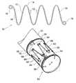
- FIG. 7shows a connection socket of a stent graft incorporating a stent according to the present invention.
- the connection socket incorporating a stent of this embodiment of the inventionmay be for a side arm for a stent graft adapted for deployment into the common iliac artery or may be for a terminal end of a leg of a bifurcated stent graft such as a for a stent graft adapted to be deployed into the aortic bifurcation.
- the tube 50may be a side arm for a stent graft or may be a terminal end of a leg of a bifurcated graft.
- the tube 50has a socket arrangement 52 into which may be placed a self-expanding stent, a balloon expandable stent or a composite stent or leg extension.
- the tube 50has a first ring 54 stitched to its terminal end and a second ring 56 spaced apart from the first ring 54 .
- Each ring 54 and 56is formed from at least two turns and preferably three turns of a nitinol wire and the ends of the nitinol wire terminate in loops 58 .
- the use of the loops 58prevent sharp ends from the NitinolTM wire from digging into the vasculature into which the stent graft is deployed.
- the stent 60is formed from a resilient wire such as nitinol wire or stainless steel and comprises a plurality of struts 62 with bends 64 between a pair of struts 62 .
- the terminal struts 66 at each endterminate in a loop 68 which comprises at least one turn of the resilient wire and preferably one and a quarter turns.
- Stitching 70is used to both hold the stent onto the tubular body 50 as well as to maintain the stent in its cylindrical or polygonal form.
- the resilient stent 60 when stitched in its cylindrical or polygonal formis made to be of a size which is at rest slightly smaller than the diameter of the tube 50 and hence when sewn on to the outside of the tube 50 using stitching 70 it provides a diameter reducing effect on the tube 50 .
- the rings 54 and 56provide firm locking for the balloon expanded covered stent and the resilient stent 60 , which is expanded by the balloon expanded stent while it is being balloon expanded, provides a compressive effect to keep tension on the balloon expanded stent.
- a firm connection and an improved sealcan be obtained between a stent leg or arm and a bridging stent.
- a similar gripping effectcan be obtained with the use of a self-expanding stent, a composite stent or other form of leg extension incorporation a stent according to the present invention.
- the side tubemay have a diameter of 8 mm and hence a circumference of 26 mm.
- Each of the ringsmay have a diameter at rest of 7 mm and the resilient stent 60 when formed into its cylindrical or polygonal form may have a diameter at rest of 6 mm.
- the first and second ringsmay be spaced apart by 10 mm and the length of the resilient stent 60 may be 6 mm. Hence there may be a gap between the rings and the resilient stent of 2 mm.
- the side armmay have a diameter of 8 mm and a length after the join to a main stent graft of up to 25 mm. It will be realised that for stent grafts to be deployed into the ascending or descending aorta with side arms to extend into their respective branch vessels other lengths and diameters will be applicable.
- FIG. 8shows a side branch stent graft or prosthesis of the type adapted for deployment into the iliac arteries, for instance, such that a bridging stent can extend from the side arm into the internal iliac or hypogastric artery.
- the stent graft 71has a main tubular body 72 and a side arm 74 . Both the main tubular body and the side arm are formed from a seamless tube of a biocompatible graft material such as Dacron. A triangular aperture is formed in the main tube and a bevel cut into the inner end of the side arm and the side arm stitched into the triangular aperture with stitching 78 .
- the side armhas a connection socket arrangement 76 at its distal end 77 .
- the connection socket arrangement 76comprises a first ring 79 stitched to its terminal or distal end 77 and a second ring 80 spaced apart from the first ring 79 .
- Each ring 79 and 80is formed from at least two turns and preferably three turns of nitinol wire and the ends of the nitinol wire terminate in loops 81 .
- the use of the loops 81prevent sharp ends from the nitinol wire from digging into the vasculature into which the stent graft is deployed.
- the stent 82is formed from a resilient wire such as nitinol wire or stainless steel and comprises a plurality of struts with bends between a pair of struts. In this embodiment there are seven struts and six bends between them.
- the terminal struts at each endterminate in a loop 85 which comprises at least one turn of the resilient wire and preferably one and a quarter turns. Stitching is used to both hold the stent onto the tubular body as well as to maintain the stent in its cylindrical or polygonal form.
- a bridging stentsuch as a balloon expandable stent
- the rings 79 and 80provide firm locking for the balloon expanded stent and the resilient stent 82 which is expanded by the balloon expanded stent while it is being balloon expanded provides a compressive effect to keep tension on the balloon expanded stent.
- a firm connection and an improved sealcan be obtained between the side arm and a bridging stent.
- a similar gripping effectcan be obtained with the use of a bridging stent in the form of a self-expanding stent, a composite stent or other form of leg extension.
Landscapes
- Health & Medical Sciences (AREA)
- Engineering & Computer Science (AREA)
- Biomedical Technology (AREA)
- Heart & Thoracic Surgery (AREA)
- Public Health (AREA)
- Transplantation (AREA)
- Cardiology (AREA)
- Veterinary Medicine (AREA)
- Oral & Maxillofacial Surgery (AREA)
- Vascular Medicine (AREA)
- Life Sciences & Earth Sciences (AREA)
- Animal Behavior & Ethology (AREA)
- General Health & Medical Sciences (AREA)
- Gastroenterology & Hepatology (AREA)
- Pulmonology (AREA)
- Prostheses (AREA)
- Media Introduction/Drainage Providing Device (AREA)
Abstract
Description
Claims (10)
Priority Applications (2)
| Application Number | Priority Date | Filing Date | Title |
|---|---|---|---|
| US11/654,423US8840657B2 (en) | 2006-01-18 | 2007-01-17 | Self expanding stent |
| US14/465,073US20170258610A9 (en) | 2006-01-18 | 2014-08-21 | Self expanding stent |
Applications Claiming Priority (2)
| Application Number | Priority Date | Filing Date | Title |
|---|---|---|---|
| US75985106P | 2006-01-18 | 2006-01-18 | |
| US11/654,423US8840657B2 (en) | 2006-01-18 | 2007-01-17 | Self expanding stent |
Related Child Applications (1)
| Application Number | Title | Priority Date | Filing Date |
|---|---|---|---|
| US14/465,073ContinuationUS20170258610A9 (en) | 2006-01-18 | 2014-08-21 | Self expanding stent |
Publications (2)
| Publication Number | Publication Date |
|---|---|
| US20070191922A1 US20070191922A1 (en) | 2007-08-16 |
| US8840657B2true US8840657B2 (en) | 2014-09-23 |
Family
ID=38006776
Family Applications (2)
| Application Number | Title | Priority Date | Filing Date |
|---|---|---|---|
| US11/654,423Active2030-03-16US8840657B2 (en) | 2006-01-18 | 2007-01-17 | Self expanding stent |
| US14/465,073AbandonedUS20170258610A9 (en) | 2006-01-18 | 2014-08-21 | Self expanding stent |
Family Applications After (1)
| Application Number | Title | Priority Date | Filing Date |
|---|---|---|---|
| US14/465,073AbandonedUS20170258610A9 (en) | 2006-01-18 | 2014-08-21 | Self expanding stent |
Country Status (4)
| Country | Link |
|---|---|
| US (2) | US8840657B2 (en) |
| EP (1) | EP1973501B1 (en) |
| AU (1) | AU2007207602B2 (en) |
| WO (1) | WO2007084537A2 (en) |
Cited By (3)
| Publication number | Priority date | Publication date | Assignee | Title |
|---|---|---|---|---|
| US9956101B2 (en) | 2014-12-04 | 2018-05-01 | Trivascular, Inc. | Internal iliac preservation devices and methods |
| US20220096252A1 (en)* | 2019-05-20 | 2022-03-31 | Seshadri Raju | Modified Z Stents for Iliac Vein Stenting |
| US11523920B2 (en) | 2017-03-16 | 2022-12-13 | Keyvon Rashidi | Stent with a smooth surface in its expanded configuration |
Families Citing this family (26)
| Publication number | Priority date | Publication date | Assignee | Title |
|---|---|---|---|---|
| US7147661B2 (en) | 2001-12-20 | 2006-12-12 | Boston Scientific Santa Rosa Corp. | Radially expandable stent |
| EP3103422A1 (en)* | 2003-03-14 | 2016-12-14 | Intersect ENT, Inc. | Sinus delivery of sustained release therapeutics |
| JP5247428B2 (en) | 2005-04-04 | 2013-07-24 | インターセクト エント, インコーポレイテッド | Apparatus and method for treating sinus symptoms |
| US8535707B2 (en) | 2006-07-10 | 2013-09-17 | Intersect Ent, Inc. | Devices and methods for delivering active agents to the osteomeatal complex |
| US20080300671A1 (en)* | 2007-06-04 | 2008-12-04 | Gil Vardi | Stent having high expansion ratio |
| EP3791826B1 (en) | 2007-12-18 | 2025-01-29 | Intersect ENT, Inc. | Self-expanding devices |
| KR100943255B1 (en)* | 2008-07-21 | 2010-02-19 | (주) 태웅메디칼 | Stent |
| AU2009276505B2 (en) | 2008-08-01 | 2015-04-23 | Intersect Ent, Inc. | Methods and devices for crimping self-expanding devices |
| EP2754463B1 (en) | 2009-05-15 | 2016-06-22 | Intersect ENT, Inc. | Expandable devices |
| US8741660B2 (en)* | 2009-05-19 | 2014-06-03 | Stokes Bio Limited | Sampling device |
| AU2009202301B8 (en) | 2009-06-10 | 2009-12-03 | Cook Incorporated | Reinforcing ring |
| US9265599B2 (en)* | 2011-08-31 | 2016-02-23 | Cleveland Clinic Foundation | Retention system for an endoluminal device |
| US10561509B2 (en) | 2013-03-13 | 2020-02-18 | DePuy Synthes Products, Inc. | Braided stent with expansion ring and method of delivery |
| AU2014236729B2 (en) | 2013-03-14 | 2018-11-22 | Intersect Ent, Inc. | Systems, devices, and method for treating a sinus condition |
| CN104116577B (en)* | 2014-06-27 | 2017-07-14 | 先健科技(深圳)有限公司 | Branch type overlay film frame |
| US10206796B2 (en) | 2014-08-27 | 2019-02-19 | DePuy Synthes Products, Inc. | Multi-strand implant with enhanced radiopacity |
| JP2018504209A (en) | 2015-01-22 | 2018-02-15 | インターセクト エント, インコーポレイテッド | Drug coated balloon |
| US10076428B2 (en) | 2016-08-25 | 2018-09-18 | DePuy Synthes Products, Inc. | Expansion ring for a braided stent |
| US10292851B2 (en) | 2016-09-30 | 2019-05-21 | DePuy Synthes Products, Inc. | Self-expanding device delivery apparatus with dual function bump |
| AU2019204522A1 (en) | 2018-07-30 | 2020-02-13 | DePuy Synthes Products, Inc. | Systems and methods of manufacturing and using an expansion ring |
| US10456280B1 (en) | 2018-08-06 | 2019-10-29 | DePuy Synthes Products, Inc. | Systems and methods of using a braided implant |
| US10278848B1 (en) | 2018-08-06 | 2019-05-07 | DePuy Synthes Products, Inc. | Stent delivery with expansion assisting delivery wire |
| US11039944B2 (en) | 2018-12-27 | 2021-06-22 | DePuy Synthes Products, Inc. | Braided stent system with one or more expansion rings |
| US20220211524A1 (en)* | 2019-03-28 | 2022-07-07 | Jms Co., Ltd. | Synthetic resin stent and stent delivery system |
| US12403291B2 (en) | 2019-08-30 | 2025-09-02 | Intersect Ent, Inc. | Submucosal bioresorbable drug eluting platform |
| KR102486166B1 (en)* | 2022-07-04 | 2023-01-09 | 주식회사 제가텍 | Stent, Method and Pin-combined Jig for Forming the Same |
Citations (19)
| Publication number | Priority date | Publication date | Assignee | Title |
|---|---|---|---|---|
| US5035706A (en)* | 1989-10-17 | 1991-07-30 | Cook Incorporated | Percutaneous stent and method for retrieval thereof |
| US5133732A (en) | 1987-10-19 | 1992-07-28 | Medtronic, Inc. | Intravascular stent |
| US5314444A (en) | 1987-03-13 | 1994-05-24 | Cook Incorporated | Endovascular stent and delivery system |
| US5451235A (en)* | 1991-11-05 | 1995-09-19 | C.R. Bard, Inc. | Occluder and method for repair of cardiac and vascular defects |
| WO1998027894A1 (en) | 1996-12-23 | 1998-07-02 | Gore Enterprise Holdings, Inc. | Implant deployment apparatus |
| EP0997115A2 (en) | 1994-04-01 | 2000-05-03 | Prograft Medical, Inc. | Self-expandable stent and stent-graft and method of using them |
| US20010039450A1 (en)* | 1999-06-02 | 2001-11-08 | Dusan Pavcnik | Implantable vascular device |
| US20030125795A1 (en)* | 1998-06-02 | 2003-07-03 | Cook Incorporated | Multiple-sided intraluminal medical device |
| US20030191521A1 (en) | 1998-07-24 | 2003-10-09 | Denardo Andrew J. | Intravascular flow modifier and reinforcement device |
| US20030199967A1 (en)* | 2002-03-25 | 2003-10-23 | Cook Incorporated | Bifurcated/branch vessel prosthesis |
| US20040117004A1 (en)* | 2002-05-16 | 2004-06-17 | Osborne Thomas A. | Stent and method of forming a stent with integral barbs |
| US20040122504A1 (en) | 2002-12-24 | 2004-06-24 | Michael Hogendijk | Vascular prosthesis and methods of use |
| US20040147997A1 (en)* | 2003-01-24 | 2004-07-29 | Gittings Darin C. | Stent delivery system and low profile stent |
| US20040167619A1 (en)* | 2003-02-26 | 2004-08-26 | Cook Incorporated | Prosthesis adapted for placement under external imaging |
| US20040176833A1 (en)* | 2002-11-22 | 2004-09-09 | Cook Incorporated | Stent tissue graft prosthesis |
| US20040186558A1 (en)* | 2001-02-05 | 2004-09-23 | Cook Incorporated | Implantable vascular device |
| US20050171598A1 (en)* | 2003-11-08 | 2005-08-04 | Schaeffer Darin G. | Aorta and branch vessel stent grafts and method |
| US20050177222A1 (en)* | 2003-12-17 | 2005-08-11 | Mead Jason A. | Interconnected leg extensions for an endoluminal prosthesis |
| US7399314B2 (en)* | 2005-11-15 | 2008-07-15 | Cordis Corporation | Systems and methods for securing graft material to intraluminal devices |
Family Cites Families (6)
| Publication number | Priority date | Publication date | Assignee | Title |
|---|---|---|---|---|
| US5733330A (en)* | 1997-01-13 | 1998-03-31 | Advanced Cardiovascular Systems, Inc. | Balloon-expandable, crush-resistant locking stent |
| US6733523B2 (en)* | 1998-12-11 | 2004-05-11 | Endologix, Inc. | Implantable vascular graft |
| AU2005206200B2 (en)* | 2004-01-20 | 2010-12-09 | Cook Medical Technologies Llc | Multiple stitches for attaching stent to graft |
| AU2005286843B2 (en)* | 2004-09-21 | 2011-07-14 | Cook Incorporated | Side branch stent graft |
| DE602005023033D1 (en)* | 2004-09-21 | 2010-09-30 | Cook Inc | STENT GRAFT CONNECTION ARRANGEMENT |
| US8864819B2 (en)* | 2004-12-17 | 2014-10-21 | Cook Medical Technologies Llc | Stented side branch graft |
- 2007
- 2007-01-17WOPCT/US2007/001195patent/WO2007084537A2/enactiveApplication Filing
- 2007-01-17EPEP07716704.7Apatent/EP1973501B1/enactiveActive
- 2007-01-17USUS11/654,423patent/US8840657B2/enactiveActive
- 2007-01-17AUAU2007207602Apatent/AU2007207602B2/enactiveActive
- 2014
- 2014-08-21USUS14/465,073patent/US20170258610A9/ennot_activeAbandoned
Patent Citations (21)
| Publication number | Priority date | Publication date | Assignee | Title |
|---|---|---|---|---|
| US5314444A (en) | 1987-03-13 | 1994-05-24 | Cook Incorporated | Endovascular stent and delivery system |
| US5133732A (en) | 1987-10-19 | 1992-07-28 | Medtronic, Inc. | Intravascular stent |
| US5035706A (en)* | 1989-10-17 | 1991-07-30 | Cook Incorporated | Percutaneous stent and method for retrieval thereof |
| US5451235A (en)* | 1991-11-05 | 1995-09-19 | C.R. Bard, Inc. | Occluder and method for repair of cardiac and vascular defects |
| EP0997115A2 (en) | 1994-04-01 | 2000-05-03 | Prograft Medical, Inc. | Self-expandable stent and stent-graft and method of using them |
| WO1998027894A1 (en) | 1996-12-23 | 1998-07-02 | Gore Enterprise Holdings, Inc. | Implant deployment apparatus |
| US20030125795A1 (en)* | 1998-06-02 | 2003-07-03 | Cook Incorporated | Multiple-sided intraluminal medical device |
| US20030191521A1 (en) | 1998-07-24 | 2003-10-09 | Denardo Andrew J. | Intravascular flow modifier and reinforcement device |
| US20010039450A1 (en)* | 1999-06-02 | 2001-11-08 | Dusan Pavcnik | Implantable vascular device |
| US20050143807A1 (en)* | 2000-02-03 | 2005-06-30 | Dusan Pavcnik | Implantable vascular device comprising a bioabsorbable frame |
| US20040210301A1 (en)* | 2000-02-03 | 2004-10-21 | Obermiller Joseph F. | Implantable vascular device |
| US20040186558A1 (en)* | 2001-02-05 | 2004-09-23 | Cook Incorporated | Implantable vascular device |
| US20030199967A1 (en)* | 2002-03-25 | 2003-10-23 | Cook Incorporated | Bifurcated/branch vessel prosthesis |
| US20040117004A1 (en)* | 2002-05-16 | 2004-06-17 | Osborne Thomas A. | Stent and method of forming a stent with integral barbs |
| US20040176833A1 (en)* | 2002-11-22 | 2004-09-09 | Cook Incorporated | Stent tissue graft prosthesis |
| US20040122504A1 (en) | 2002-12-24 | 2004-06-24 | Michael Hogendijk | Vascular prosthesis and methods of use |
| US20040147997A1 (en)* | 2003-01-24 | 2004-07-29 | Gittings Darin C. | Stent delivery system and low profile stent |
| US20040167619A1 (en)* | 2003-02-26 | 2004-08-26 | Cook Incorporated | Prosthesis adapted for placement under external imaging |
| US20050171598A1 (en)* | 2003-11-08 | 2005-08-04 | Schaeffer Darin G. | Aorta and branch vessel stent grafts and method |
| US20050177222A1 (en)* | 2003-12-17 | 2005-08-11 | Mead Jason A. | Interconnected leg extensions for an endoluminal prosthesis |
| US7399314B2 (en)* | 2005-11-15 | 2008-07-15 | Cordis Corporation | Systems and methods for securing graft material to intraluminal devices |
Cited By (6)
| Publication number | Priority date | Publication date | Assignee | Title |
|---|---|---|---|---|
| US9956101B2 (en) | 2014-12-04 | 2018-05-01 | Trivascular, Inc. | Internal iliac preservation devices and methods |
| US11033413B2 (en) | 2014-12-04 | 2021-06-15 | Trivascular, Inc. | Internal iliac preservation devices and methods |
| US11918498B2 (en) | 2014-12-04 | 2024-03-05 | Trivascular, Inc. | Internal iliac preservation devices and methods |
| US11523920B2 (en) | 2017-03-16 | 2022-12-13 | Keyvon Rashidi | Stent with a smooth surface in its expanded configuration |
| US20220096252A1 (en)* | 2019-05-20 | 2022-03-31 | Seshadri Raju | Modified Z Stents for Iliac Vein Stenting |
| US11666466B2 (en)* | 2019-05-20 | 2023-06-06 | Seshadri Raju | Modified Z stents for iliac vein stenting |
Also Published As
| Publication number | Publication date |
|---|---|
| EP1973501A2 (en) | 2008-10-01 |
| WO2007084537A3 (en) | 2007-09-07 |
| AU2007207602B2 (en) | 2012-08-23 |
| US20170258610A9 (en) | 2017-09-14 |
| EP1973501B1 (en) | 2013-10-16 |
| WO2007084537A2 (en) | 2007-07-26 |
| US20070191922A1 (en) | 2007-08-16 |
| AU2007207602A1 (en) | 2007-07-26 |
| US20140364936A1 (en) | 2014-12-11 |
Similar Documents
| Publication | Publication Date | Title |
|---|---|---|
| US8840657B2 (en) | Self expanding stent | |
| US11771573B2 (en) | Side branch stent graft | |
| US9775731B2 (en) | Ring stent | |
| US6860900B2 (en) | Stent and stent-graft for treating branched vessels | |
| US9237959B2 (en) | Stent and barb | |
| US20210015643A1 (en) | Low profile non-symmetrical stent | |
| US8663309B2 (en) | Asymmetric stent apparatus and method | |
| US8025694B2 (en) | Modular vascular prosthesis and methods of use | |
| US7905915B2 (en) | Z-stent with incorporated barbs | |
| US20050033406A1 (en) | Branch vessel stent and graft | |
| US20140222132A1 (en) | Percutaneous endoprosthesis using suprarenal fixation and barbed anchors |
Legal Events
| Date | Code | Title | Description |
|---|---|---|---|
| AS | Assignment | Owner name:COOK INCORPORATED, INDIANA Free format text:ASSIGNMENT OF ASSIGNORS INTEREST;ASSIGNOR:HARTLEY, DAVID ERNEST;REEL/FRAME:019172/0153 Effective date:20070313 Owner name:WILLIAM A. COOK AUSTRALIA PTY. LTD., AUSTRALIA Free format text:ASSIGNMENT OF ASSIGNORS INTEREST;ASSIGNOR:HARTLEY, DAVID ERNEST;REEL/FRAME:019172/0153 Effective date:20070313 | |
| AS | Assignment | Owner name:COOK MEDICAL TECHNOLOGIES LLC, INDIANA Free format text:ASSIGNMENT OF ASSIGNORS INTEREST;ASSIGNORS:COOK INCORPORATED;WILLIAM A. COOK AUSTRALIA PTY. LTD.;REEL/FRAME:033158/0626 Effective date:20140619 | |
| STCF | Information on status: patent grant | Free format text:PATENTED CASE | |
| MAFP | Maintenance fee payment | Free format text:PAYMENT OF MAINTENANCE FEE, 4TH YEAR, LARGE ENTITY (ORIGINAL EVENT CODE: M1551) Year of fee payment:4 | |
| MAFP | Maintenance fee payment | Free format text:PAYMENT OF MAINTENANCE FEE, 8TH YEAR, LARGE ENTITY (ORIGINAL EVENT CODE: M1552); ENTITY STATUS OF PATENT OWNER: LARGE ENTITY Year of fee payment:8 | |
| AS | Assignment | Owner name:WILMINGTON TRUST, NATIONAL ASSOCIATION, AS COLLATERAL AGENT, DELAWARE Free format text:SECURITY INTEREST;ASSIGNOR:COOK MEDICAL TECHNOLOGIES LLC;REEL/FRAME:066700/0277 Effective date:20240227 |