US8840639B2 - Apparatus for performing an electrosurgical procedure - Google Patents
Apparatus for performing an electrosurgical procedureDownload PDFInfo
- Publication number
- US8840639B2 US8840639B2US12/915,809US91580910AUS8840639B2US 8840639 B2US8840639 B2US 8840639B2US 91580910 AUS91580910 AUS 91580910AUS 8840639 B2US8840639 B2US 8840639B2
- Authority
- US
- United States
- Prior art keywords
- lock assembly
- housing
- distal end
- assembly
- movable handle
- Prior art date
- Legal status (The legal status is an assumption and is not a legal conclusion. Google has not performed a legal analysis and makes no representation as to the accuracy of the status listed.)
- Active, expires
Links
Images


Classifications
- A—HUMAN NECESSITIES
- A61—MEDICAL OR VETERINARY SCIENCE; HYGIENE
- A61B—DIAGNOSIS; SURGERY; IDENTIFICATION
- A61B18/00—Surgical instruments, devices or methods for transferring non-mechanical forms of energy to or from the body
- A61B18/04—Surgical instruments, devices or methods for transferring non-mechanical forms of energy to or from the body by heating
- A61B18/12—Surgical instruments, devices or methods for transferring non-mechanical forms of energy to or from the body by heating by passing a current through the tissue to be heated, e.g. high-frequency current
- A61B18/14—Probes or electrodes therefor
- A61B18/1442—Probes having pivoting end effectors, e.g. forceps
- A61B18/1445—Probes having pivoting end effectors, e.g. forceps at the distal end of a shaft, e.g. forceps or scissors at the end of a rigid rod
- A—HUMAN NECESSITIES
- A61—MEDICAL OR VETERINARY SCIENCE; HYGIENE
- A61B—DIAGNOSIS; SURGERY; IDENTIFICATION
- A61B17/00—Surgical instruments, devices or methods
- A61B17/28—Surgical forceps
- A61B17/29—Forceps for use in minimally invasive surgery
- A61B17/2909—Handles
- A—HUMAN NECESSITIES
- A61—MEDICAL OR VETERINARY SCIENCE; HYGIENE
- A61B—DIAGNOSIS; SURGERY; IDENTIFICATION
- A61B17/00—Surgical instruments, devices or methods
- A61B17/28—Surgical forceps
- A61B17/29—Forceps for use in minimally invasive surgery
- A61B2017/2946—Locking means
- A—HUMAN NECESSITIES
- A61—MEDICAL OR VETERINARY SCIENCE; HYGIENE
- A61B—DIAGNOSIS; SURGERY; IDENTIFICATION
- A61B18/00—Surgical instruments, devices or methods for transferring non-mechanical forms of energy to or from the body
- A61B2018/00053—Mechanical features of the instrument of device
- A—HUMAN NECESSITIES
- A61—MEDICAL OR VETERINARY SCIENCE; HYGIENE
- A61B—DIAGNOSIS; SURGERY; IDENTIFICATION
- A61B18/00—Surgical instruments, devices or methods for transferring non-mechanical forms of energy to or from the body
- A61B2018/0091—Handpieces of the surgical instrument or device
Definitions
- the present disclosurerelates to an electrosurgical forceps. More particularly, the present disclosure relates to a lock assembly for use with a variety of endoscopic electrosurgical forceps for sealing and/or cutting various tissue structures.
- Electrosurgical instrumentse.g., electrosurgical forceps (closed type) are well known in the medical arts and typically include a housing, a handle assembly including a movable handle, a shaft and an end effector assembly attached to a distal end of the shaft.
- the end effectorincludes jaw members configured to manipulate tissue (e.g., grasp and seal tissue).
- the electrosurgical forcepsutilizes both mechanical clamping action and electrical energy to effect hemostasis by heating the tissue and blood vessels to coagulate, cauterize, seal, cut, desiccate, and/or fulgurate tissue.
- one or more driving mechanismse.g., a drive assembly including a drive element
- one or more componentsoperatively associated with the handle assembly to impart movement to one or both of the jaw members.
- one or more clamping springsmay be operably associated with the handle assembly, end effector and/or the driving mechanisms.
- the movable handlemay be configured to lock, via the clamping spring, the jaw members in a clamping position onto tissue disposed therebetween.
- This type of locking methodi.e., locking the movable handle in the closed position, transfers a portion of the locking force from the compressed clamping spring through the movable handle and to its locking point, i.e., the jaw members.
- handle or lever “flex”changes the compression force of the clamping spring and, thus, reduces or greatly diminishes jaw clamping forces on tissue.
- this reduced clamping force on tissue provided by the jaw membersmay result in a non-uniform and/or ineffective tissue seal, which, in turn, may be deleterious to a patient.
- the present disclosureprovides an endoscopic forceps.
- the endoscopic forcepsincludes a housing having a shaft that extends therefrom and defines a longitudinal axis therethrough.
- a handle assemblyincludes a movable handle movable relative to the housing.
- the movable handleincludes one or more mechanical interfaces disposed thereon.
- An end effector assemblyoperatively connects to a distal end of the shaft and includes a pair of first and second jaw members pivotably coupled to one another.
- One (or in some instances both) of the first and second jaw membersis movable relative to the other from an open or neutral position, wherein the first and second jaw members are disposed in spaced relation relative to one another, to a clamping position, wherein the first and second jaw members cooperate to grasp tissue therebetween.
- a drive assemblyincludes a resilient member operably associated therewith.
- a lock assemblyoperably couples to the housing about a pivot point, and is in operative communication with the movable handle via one or more mechanical interfaces disposed thereon.
- the lock assemblyis movable with the handle assembly.
- the one or more mechanical interfacesmoves along the lock assembly when the movable handle is moved proximally causing the lock assembly to rotate about the pivot point and into communication with the resilient member such that the resilient member is prevented from moving distally against the bias provided therefrom such that the first and second jaw members remain in the clamping position.
- the present disclosureprovides electrosurgical forceps.
- the electrosurgical forcepsincludes a housing having a shaft with a distal end thereof having an end effector assembly operatively connected thereto.
- the end effectorincludes a pair of first and second jaw members pivotably coupled and movable relative to one another from an open or neutral position to a clamping position.
- a movable handleis movable relative to the housing and includes one or more mechanical interfaces disposed thereon.
- a drive assemblyincludes a resilient member operably associated therewith.
- a lock assemblyoperably couples to the housing about a pivot point and is in operative communication with the movable handle via the one or more mechanical interfaces disposed thereon.
- the one or more mechanical interfacesmoves along the lock assembly when the movable handle is moved proximally causing the lock assembly to rotate about the pivot point and into communication with the resilient member such that the resilient member is prevented from moving distally against the bias provided therefrom such that the first and second jaw members remain in the clamping position.
- the present disclosurealso provides a lock assembly for use with a surgical instrument.
- the lock assemblyincludes a state changing feature having a beam spring at one end thereof and a locking member at an opposite end thereof.
- the locking memberincludes a generally arcuate configuration.
- the state changing featureincludes a generally arcuate proximal end.
- the beam springis selectively engageable with a housing of the surgical instrument and is configured to rotate the lock assembly in a clockwise and counterclockwise direction and into and out of communication with the housing upon actuation of the lock assembly.
- FIG. 1Ais a perspective view of a bipolar forceps shown in open configuration and including a housing, a shaft, handle assembly, a lock assembly, trigger assembly and an end effector assembly according to the present disclosure;
- FIG. 1Bis a perspective view of the bipolar forceps of FIG. 1A shown in closed configuration
- FIGS. 2A-2Dare side, cut-away views of the bipolar forceps of FIG. 1A with the internal working components of the bipolar forceps exposed showing the handle assembly and the lock assembly in various positions;
- FIG. 3is a left perspective view of the lock assembly depicted in FIGS. 2A-2D ;
- FIG. 4is a right perspective view of the lock assembly
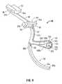
- FIG. 5is a rear perspective view of the lock assembly
- FIG. 6is a left side view of the lock assembly
- FIG. 7is a right side view of the lock assembly.
- proximalas is traditional, will refer to an end which is closer to the user, while the term “distal” will refer to an end that is farther from the user.
- FIGS. 1A and 1Bshow in detail the operating features and inter-cooperating components of an endoscopic bipolar forceps for use with the present disclosure generally identified as forceps 10 .
- forceps 10is for use with various surgical procedures and includes: a housing 20 ; a rotating assembly 80 ; a trigger assembly 70 ; a switch 60 ; an electrosurgical cable 310 for connecting the forceps 10 to an electrosurgical generator (not shown); and an end effector assembly 100 . These various components mutually cooperate to grasp, seal and divide tubular vessels and vascular tissues.
- forceps 10includes a shaft 12 that has a distal end 16 configured to mechanically engage the end effector assembly 100 operably associated with the forceps 10 and a proximal end 14 that mechanically engages the housing 20 .
- Drive assembly 130includes a reciprocating drive sleeve 134 slidingly disposed within the shaft 12 that is remotely operable by the drive assembly 130 . Specifically, proximal movement of the drive assembly 130 via actuation of handle assembly 30 causes the drive sleeve 134 to reciprocate proximally.
- the jaw members 110 and 120pivot about a pivot pin 95 disposed through respective pivot holes disposed within flanges 113 and 123 , as best seen in FIG. 1A .
- One or more resilient membersare operably associated with drive assembly 130 and are configured to bias the drive assembly including the drive sleeve 134 distally such that the jaw members 110 and 120 are disposed in a normally open or neutral position.
- a spring cartridge 133is operably disposed in the housing 20 and houses and/or supports one or more suitable springs (not explicitly shown) therein.
- Spring cartridge 133is configured (in conjunction with a movable handle 40 ) to hold or maintain one or both of the jaw members 110 and 120 in a closed or clamping position when the movable handle 40 is moved to a locked position, described in greater detail below.
- Handle assembly 30includes a fixed handle 50 and movable handle 40 ( FIGS. 1A-2D ).
- fixed handle 50is integrally associated with housing 20 .
- Movable handle 40 of handle assembly 30is ultimately connected to drive assembly 130 (see FIG. 2A , for example) to impart movement of the jaw members 110 and 120 from the open position ( FIG. 1A ) wherein the jaw members 110 and 120 are disposed in spaced relation relative to one another, to a clamping or closed position ( FIG. 1B ) wherein the jaw members 110 and 120 cooperate to grasp tissue therebetween.
- movable handle 40is selectively movable about a pivot pin 45 from a first position relative to fixed handle 50 to a second position in closer proximity to the fixed handle 50 that imparts movement of the jaw members 110 and 120 relative to one another. As explained in more detail below, continued proximal movement of the movable handle 40 places the movable handle 40 in a locked position, wherein the jaw members 110 and 120 are maintained in the clamping position.
- the movable handle 40is moved proximally past the locked position through a release stroke such that the lock feature 91 releases the spring cartridge and allows movable handle 40 is allowed to move freely, i.e., distally, toward the distal position and the jaw members 110 and 120 return to the open position.
- the movable handle 40includes a clevis 46 that forms a pair of flanges (only a right upper flange 46 a is described herein). Unless otherwise stated, it is to be understood that the left upper flange includes the same components and is configured to function similar to that of right upper flange 46 a .
- Right upper flange 46 ahas an aperture (not explicitly shown) at an upper end thereof for receiving pivot 45 therethrough and mounting the upper end of the handle 40 to the housing 20 .
- Upper flange 46 aincludes a drive flange 47 a that is aligned along longitudinal axis “A-A” (see FIG.
- Movable handle 40provides a distinct mechanical advantage over conventional handle assemblies due to the unique position of the pivot pin 45 relative to the longitudinal axis “A-A” of the shaft 12 and the disposition of the drive flange 47 a (and a drive flange associated with the upper left flange) along longitudinal axis “A-A”.
- a usergains a mechanical advantage to actuate the jaw members 110 and 120 enabling the user to close the jaw members 110 and 120 with less force while still generating the required forces necessary to affect a proper and effective tissue seal.
- One or more mechanical interfacesare operably disposed on the movable handle 40 .
- a pin 48(see, FIG. 2A ) of suitable proportion is operably disposed on either (or in certain instances both) sides of the movable handle 40 and on a portion of the movable handle 40 that is configured to move within the confines of the housing 20 .
- pin 48is shown operably disposed on an interior right side of the movable handle 40 .
- the pin 48is configured to move along a cartridge lock assembly 90 (lock assembly 90 ) when the movable handle 40 is moved proximally, described in greater detail below.
- Pin 48operably couples to lock assembly 90 to pivotally move the lock assembly 90 into a lock position thereby blocking the spring cartridge 133 and for limiting distal movement of the drive assembly 130 including spring cartridge 133 and drive sleeve 134 when the movable handle 40 is moved proximally past a predetermined position and to a locked position.
- Lock assembly 90may be made from any suitable material including but not limited to plastic, metal, metal alloy, etc. In the illustrated embodiment, lock assembly 90 is made from plastic and is of unitary construction. Alternatively, the components that make up the lock assembly 90 may be joined or coupled together by one or more suitable coupling methods, e.g., adhesive.
- Lock assembly 90pivotably couples to the housing 20 about a pivot point.
- one or more suitable pivot devices and/or mechanismspivotably couples the lock assembly 90 to the housing 20 .
- a pivot pin 94includes a generally elongated configuration having a pair of lateral edges 94 a that extend laterally across the lock assembly 90 , see FIGS. 3-5 .
- the pair of lateral edges 94 aoperably couples the pivot pin 94 to an internal frame of the housing 20 such that the pivot pin 94 pivots thereabout.
- the pair of lateral edges 94 aare configured to rotatably reside in a pair of corresponding cavities or bores 20 a (shown in phantom in FIGS. 2A-2D ) operably disposed on the internal frame of the housing 20 .
- Proximal movement of the movable handle 40moves the pin 48 along the lock assembly 90 .
- the lock assembly 90rotates about the pivot pin 94 and contacts, i.e., blocks, the spring cartridge 133 such that the spring cartridge 133 is prevented from moving distally against the bias provided therefrom, which, in turn, maintains the movable handle 40 in the locked position and the jaw members 110 and 120 in the clamping position (see FIG. 1B in combination with FIGS. 2A and 2C ).
- Pivot pin 94is supported on the lock assembly 90 by two support beams 95 that are disposed at right angles with respect to each other ( FIG. 3 ).
- Support beams 95include arcuate distal edges that are contoured to cradle the pivot pin 94 therein. The contoured distal edges of the support beams 95 facilitate rotation of the pivot pin 48 in the relatively limited space within the housing 20 .
- lock assembly 90is illustrated including a locking member 91 , a beam spring 92 and a state changing feature 93 .
- Locking member 91is operably disposed at a distal end 96 of the lock assembly 90 .
- Locking member 91is configured to contact a distal end 135 of the spring cartridge 133 and a distal end 23 of the housing 20 when the movable handle 40 is moved proximally to the locked position, i.e., the locking member 91 is “wedged” or “sandwiched” between the distal end 135 of the spring cartridge 133 and the distal end 23 of the housing 20 (as best seen in FIG. 2C ) thereby carrying the entire clamping force from the spring cartridge 133 in compression directly to the proximal end 14 of the shaft, thus, bypassing the handle flex.
- the jaw members 110 and 120remain in the clamping position until a user moves the movable handle 40 proximally past the locked position through the release stroke, described in greater detail below.
- Locking member 91includes a generally arcuate or concave configuration having top and bottom portions 91 e and 91 f , respectively, and four sidewalls 91 a - 91 d , see FIGS. 3-5 .
- the arcuate or concave configuration of the locking member 91follows the generally cylindrical contour of the distal end 135 of the spring cartridge 133 .
- This arcuate or concave configuration of the locking member 91is designed to evenly distribute (or concentrate) a load provided by the spring cartridge 133 against locking member 91 , e.g., sidewall 91 a .
- Locking member 91is supported at the distal end 96 by a generally rectangular support beam 98 that extends from the pivot pin 94 adjacent the support beams 95 to the bottom portion 91 f of the locking member 91 , see FIGS. 3-5 .
- the support beam 98is configured such that one or more features, e.g., trigger assembly 70 , associated with the forceps 10 are operable thereabout. More particularly, the support beam 98 is configured such that the trigger assembly 70 is pivotably movable therealong and between the pivot 94 and locking member 91 , see FIGS. 2A-2D . Positioning the trigger assembly 70 in this manner facilitates pivoting of trigger assembly 70 in the relatively limited space within the housing 20 .
- the support beam 98may be configured to support or guide the trigger assembly 70 .
- support beam 98also functions as a resilient member. More particularly, when state changing feature 93 is forced downward by pin 48 , the locking member 91 is forced into contact with a bottom portion of the spring cartridge 133 . The support beam 98 flexes until the spring cartridge 133 is fully proximal, at which point the force provided by the flexed support beam 98 drives the locking member 91 into a space between the distal end 135 of the spring cartridge 133 and an inside surface of distal end 23 of the housing 20 . As a result thereof, all force of the spring cartridge is carried in compression by the locking member 91 and not through the sidewalls and fixed handle parts of the housing 20 .
- state changing feature 93(feature 93 ) is operably disposed between the pivot pin 94 and the beam spring 92 .
- Feature 93may include any suitable configuration that is suitable for the intended purposes described herein. More particularly, feature 93 is configured to pivotally move the lock assembly 90 including the locking member 91 such that the locking member 91 is forced between the spring cartridge 133 and the distal end 23 of the housing 20 .
- feature 93may include one or more cut-outs, protuberances, detents, intents, grooves, channels, railways, etc. that individually or collectively pivotally move the lock assembly 90 .
- the feature 93is configured to accommodate various configurations of pin 48 and/or movable handle 40 , i.e. placement of the pin 48 on an interior left side of the movable handle 40 or the interior right side of the movable handle 40 .
- pin 48is described in terms of use on the interior right side of the movable handle 40
- the operative components of the feature 93 that are configured for use with the pin 48 on the right interior side of the movable handle 40are described hereinafter.
- a railway 97extends along an outer periphery of the feature 93 from the support beams 95 of the pivot 94 to a proximal end 99 of the feature 93 adjacent the beam spring 92 ( FIGS. 3 , 4 , 6 and 7 ).
- Railway 97includes two generally slanted or beveled sidewalls of suitable proportion, see FIGS. 3 and 4 , respectively. More particularly, railway 97 includes a right sidewall 97 a and a left sidewall 97 b . The slanted or beveled sidewalls 97 a and 97 b prevent the pin 48 from engaging or “catching on” the railway 97 as the lock assembly 90 moves distally to the open position.
- railway 97functions as a resilient member. More particularly, when state changing feature 93 is forced downward by pin 48 , the locking member 91 is forced into contact with a bottom portion of the spring cartridge 133 . The railway 97 flexes until the spring cartridge 133 is fully proximal, at which point the force provided by the flexed railway 97 drives the locking member 91 into a space between the distal end 135 of the spring cartridge 133 and an inside surface of distal end 23 of the housing.
- Proximal end 101is configured to selectively and releasably engage the pin 48 therein to thereby rotate the lock assembly 90 counterclockwise into the locked position, as best seen in FIG. 2C .
- the proximal end 101is suitably proportioned and includes one or more suitable configurations.
- proximal end 101includes a generally “boot” like configuration having a generally arcuate proximal sidewall 102 defining a cul-de-sac 104 thereabout ( FIGS. 3 , 4 , 6 and 7 ).
- Cul-de-sac 104includes a bottom portion 105 with a generally arcuate configuration that is configured to slidably engage the pin 48 when the movable handle 40 is moved proximally past the locked position and through the release stroke ( FIG. 3 ).
- the arcuate configuration of the bottom portion 105maintains the pin 48 within the confines of the cul-de-sac 104 and provides a smooth transition therefrom when the movable handle 40 is moved proximally past the locked position and through the release stroke.
- Cul-de-sac 104is proportioned to selectively and releasably engage or “cradle” the pin 48 when feature 93 moves upward against 48 during the proximal motion of the movable handle 40 ( FIG. 2C ).
- a generally elongated portion 107is operably disposed adjacent the proximal portion 101 and is configured to arrest the upward motion of feature 93 against pin 48 and allow pin 48 into and out of the cul-de-sac 104 ( FIGS. 3-7 ). More particularly, elongated portion 107 is configured to catch or trap itself on the pin 48 when the pin 48 is moved past a proximal end 103 ( FIG. 3 ). That is, as the movable handle 40 and pin 48 moves distally into the locked position, the elongated portion 107 catches the pin 48 and prevents the lock assembly 90 from rotating counterclockwise out of the locked position.
- a distal end 108is configured to help rotate the lock assembly 90 counterclockwise as pin 48 moves to the top portion 103 of the proximal end 101 .
- the distal end 108includes a top portion 108 a with a generally slanted, elongated configuration, see FIGS. 3-7 .
- a bottom portion 108 bis configured to help guide the pin 48 along the railway 97 a and back toward to the support beam 95 .
- the lock assembly 90includes a beam spring 92 .
- Beam spring 92may include any suitable configuration.
- the beam spring 92includes a generally arcuate configuration having relatively flat proximal and distal faces 92 c and 92 d ( FIGS. 3 and 5 ), respectively.
- Beam spring 92includes proximal and distal ends 92 a and 92 b , respectively.
- Distal end 92 boperably couples to the feature 93 .
- Proximal end 92 ais in operative communication with the housing 20 . More particularly, proximal end 92 a is movably disposed within a cavity 25 (of suitable proportion) of the housing 20 ( FIGS. 2A and 2 B).
- Proximal end 92 ais configured to move out of communication with the cavity 25 when the movable handle 40 is moved to the locked position ( FIG. 2C ) and back into communication with the cavity 25 when the movable handle 40 is moved out of the locked position, see FIG. 2D , for example.
- Beam spring 92(in conjunction with the feature 93 ) is configured to rotate the locking member 91 about the pivot pin 94 in a clockwise direction. More particularly, as the pin 48 moves along the railway 97 ( FIGS. 2A-2D ) and into communication with the proximal end 101 , the proximal end 92 a of the beam spring 92 flexes against the internal frame of the housing 20 , as best seen in FIGS. 2A and 2B . With the pin 48 positioned in the cul-de-sac 104 , the proximal end 92 a of the beam spring 92 is disposed within the movable handle 40 .
- movable handle 40In use, movable handle 40 , initially, is positioned in a distal position ( FIGS. 1A and 2A ). In the distal position, the jaw members 110 and 120 are in the open position and the pin 48 is positioned along the railway 97 between the pivot pin 94 and locking member 91 that, at this time, is not disposed between the distal end 135 of the spring cartridge 133 and distal end 23 of the housing 20 . That is, the spring cartridge 133 is biased against the internal frame of the housing 20 . Moreover, the proximal end 92 a of the spring beam 92 is positioned within the cavity 23 .
- Proximal movement of the moveable handle 40moves the spring cartridge 133 proximally against the bias of the spring contained therein ( FIG. 2B ), which, in turn, moves the jaw members 110 and 120 toward one another and into the clamping position.
- Proximal movement of the movable handle 40also moves the pin 48 proximally along the railway 97 and toward feature 93 .
- the feature 93causes the proximal end 92 a of the beam spring 92 to flex against the internal frame of the housing 20 ( FIG. 2B ).
- Moveable handle 40is moved proximally to the locked position ( FIG. 2C ).
- the pin 48is positioned within the cul-de-sac 104 of the feature 93 and the locking member 91 is positioned between the distal end 135 of the spring cartridge 133 and the distal end 25 of the housing 20 .
- the spring cartridge 133is prevented from moving distally toward the distal end 23 of the housing 20 .
- the jaw members 110 and 120are maintained in the clamping position under the force provided by the spring contained in the cartridge 133 ( FIGS. 1B and 2C ).
- the springIn the clamping position, the spring provides a closure force at the jaw members 110 and 120 for sealing tissue, e.g., in the range of about 3 kg/cm 2 to about 16 kg/cm 2 .
- the unique configuration of the locking assembly 90transfers the spring forces from the compressed spring to the internal frame of the housing 20 via the locking member 91 .
- the entire spring forceis carried in compression by the locking member 91 directly between the proximal end 14 of the shaft 12 and the distal end 135 of the spring cartridge 133 .
- thisreduces and/or greatly diminishes handle or lever “flex” that is typically associated with conventional forceps.
- movable handle 40To unlock movable handle 40 from the locked position, movable handle 40 is moved proximally past the locked position through a release stroke, which, in turn, disengages the pin 48 from the cul-de-sac 104 ( FIG. 2D ). With the pin 48 disengaged from the cul-de-sac 104 , the proximal end 92 a of the spring beam 92 returns back to the cavity 25 where the proximal end 92 a contacts and flexes against the internal frame of the housing 20 , which, in turn, pivots the locking member 91 about the pivot 94 and moves the locking member 91 clockwise and out of engagement with the distal end 125 of the spring cartridge 133 and the distal end 23 of the housing 20 ( FIG. 2D ).
- one or more resilient memberse.g., compression spring (not shown) may be operably associated with or coupled to either the movable handle 40 and/or locking assembly 90 .
Landscapes
- Health & Medical Sciences (AREA)
- Surgery (AREA)
- Engineering & Computer Science (AREA)
- Life Sciences & Earth Sciences (AREA)
- Biomedical Technology (AREA)
- Otolaryngology (AREA)
- Nuclear Medicine, Radiotherapy & Molecular Imaging (AREA)
- Plasma & Fusion (AREA)
- Physics & Mathematics (AREA)
- Heart & Thoracic Surgery (AREA)
- Medical Informatics (AREA)
- Molecular Biology (AREA)
- Animal Behavior & Ethology (AREA)
- General Health & Medical Sciences (AREA)
- Public Health (AREA)
- Veterinary Medicine (AREA)
- Surgical Instruments (AREA)
Abstract
Description
1. Technical Field
The present disclosure relates to an electrosurgical forceps. More particularly, the present disclosure relates to a lock assembly for use with a variety of endoscopic electrosurgical forceps for sealing and/or cutting various tissue structures.
2. Description of Related Art
Electrosurgical instruments, e.g., electrosurgical forceps (closed type), are well known in the medical arts and typically include a housing, a handle assembly including a movable handle, a shaft and an end effector assembly attached to a distal end of the shaft. The end effector includes jaw members configured to manipulate tissue (e.g., grasp and seal tissue). Typically, the electrosurgical forceps utilizes both mechanical clamping action and electrical energy to effect hemostasis by heating the tissue and blood vessels to coagulate, cauterize, seal, cut, desiccate, and/or fulgurate tissue. Usually, one or more driving mechanisms, e.g., a drive assembly including a drive element, is utilized to cooperate with one or more components operatively associated with the handle assembly to impart movement to one or both of the jaw members. To facilitate clamping the jaw members onto tissue, one or more clamping springs (or other suitable device(s)) may be operably associated with the handle assembly, end effector and/or the driving mechanisms.
In certain instances, the movable handle may be configured to lock, via the clamping spring, the jaw members in a clamping position onto tissue disposed therebetween. This type of locking method, i.e., locking the movable handle in the closed position, transfers a portion of the locking force from the compressed clamping spring through the movable handle and to its locking point, i.e., the jaw members. Over time, however, what is typically referred to in the art as handle or lever “flex” changes the compression force of the clamping spring and, thus, reduces or greatly diminishes jaw clamping forces on tissue. In the instance where the jaw members are configured to grasp, clamp and, subsequently, seal tissue, this reduced clamping force on tissue provided by the jaw members may result in a non-uniform and/or ineffective tissue seal, which, in turn, may be deleterious to a patient.
The present disclosure provides an endoscopic forceps. The endoscopic forceps includes a housing having a shaft that extends therefrom and defines a longitudinal axis therethrough. A handle assembly includes a movable handle movable relative to the housing. The movable handle includes one or more mechanical interfaces disposed thereon. An end effector assembly operatively connects to a distal end of the shaft and includes a pair of first and second jaw members pivotably coupled to one another. One (or in some instances both) of the first and second jaw members is movable relative to the other from an open or neutral position, wherein the first and second jaw members are disposed in spaced relation relative to one another, to a clamping position, wherein the first and second jaw members cooperate to grasp tissue therebetween. A drive assembly includes a resilient member operably associated therewith. A lock assembly operably couples to the housing about a pivot point, and is in operative communication with the movable handle via one or more mechanical interfaces disposed thereon. The lock assembly is movable with the handle assembly. The one or more mechanical interfaces moves along the lock assembly when the movable handle is moved proximally causing the lock assembly to rotate about the pivot point and into communication with the resilient member such that the resilient member is prevented from moving distally against the bias provided therefrom such that the first and second jaw members remain in the clamping position.
The present disclosure provides electrosurgical forceps. The electrosurgical forceps includes a housing having a shaft with a distal end thereof having an end effector assembly operatively connected thereto. The end effector includes a pair of first and second jaw members pivotably coupled and movable relative to one another from an open or neutral position to a clamping position. A movable handle is movable relative to the housing and includes one or more mechanical interfaces disposed thereon. A drive assembly includes a resilient member operably associated therewith. A lock assembly operably couples to the housing about a pivot point and is in operative communication with the movable handle via the one or more mechanical interfaces disposed thereon. The one or more mechanical interfaces moves along the lock assembly when the movable handle is moved proximally causing the lock assembly to rotate about the pivot point and into communication with the resilient member such that the resilient member is prevented from moving distally against the bias provided therefrom such that the first and second jaw members remain in the clamping position.
The present disclosure also provides a lock assembly for use with a surgical instrument. The lock assembly includes a state changing feature having a beam spring at one end thereof and a locking member at an opposite end thereof. The locking member includes a generally arcuate configuration. The state changing feature includes a generally arcuate proximal end. The beam spring is selectively engageable with a housing of the surgical instrument and is configured to rotate the lock assembly in a clockwise and counterclockwise direction and into and out of communication with the housing upon actuation of the lock assembly.
Various embodiments of the present disclosure are described hereinbelow with references to the drawings, wherein:
Detailed embodiments of the present disclosure are disclosed herein; however, the disclosed embodiments are merely examples of the disclosure, which may be embodied in various forms. Therefore, specific structural and functional details disclosed herein are not to be interpreted as limiting, but merely as a basis for the claims and as a representative basis for teaching one skilled in the art to variously employ the present disclosure in virtually any appropriately detailed structure.
In the drawings and in the descriptions that follow, the term “proximal,” as is traditional, will refer to an end which is closer to the user, while the term “distal” will refer to an end that is farther from the user.
With continued reference toFIGS. 1A and 1B ,forceps 10 includes ashaft 12 that has adistal end 16 configured to mechanically engage theend effector assembly 100 operably associated with theforceps 10 and aproximal end 14 that mechanically engages thehousing 20.
With reference toFIGS. 2A-2D ,drive assembly 130 is illustrated.Drive assembly 130 includes areciprocating drive sleeve 134 slidingly disposed within theshaft 12 that is remotely operable by thedrive assembly 130. Specifically, proximal movement of thedrive assembly 130 via actuation ofhandle assembly 30 causes thedrive sleeve 134 to reciprocate proximally. Thejaw members pivot pin 95 disposed through respective pivot holes disposed withinflanges 113 and123, as best seen inFIG. 1A .
One or more resilient members (e.g., springs not explicitly shown) are operably associated withdrive assembly 130 and are configured to bias the drive assembly including thedrive sleeve 134 distally such that thejaw members spring cartridge 133 is operably disposed in thehousing 20 and houses and/or supports one or more suitable springs (not explicitly shown) therein.Spring cartridge 133 is configured (in conjunction with a movable handle40) to hold or maintain one or both of thejaw members movable handle 40 is moved to a locked position, described in greater detail below.
Handleassembly 30 includes a fixedhandle 50 and movable handle40 (FIGS. 1A-2D ). In one particular embodiment, fixedhandle 50 is integrally associated withhousing 20.Movable handle 40 ofhandle assembly 30 is ultimately connected to drive assembly130 (seeFIG. 2A , for example) to impart movement of thejaw members FIG. 1A ) wherein thejaw members FIG. 1B ) wherein thejaw members
As best seen inFIGS. 2A-2D ,movable handle 40 is selectively movable about apivot pin 45 from a first position relative to fixedhandle 50 to a second position in closer proximity to the fixedhandle 50 that imparts movement of thejaw members movable handle 40 places themovable handle 40 in a locked position, wherein thejaw members movable handle 40 from the locked position, themovable handle 40 is moved proximally past the locked position through a release stroke such that thelock feature 91 releases the spring cartridge and allowsmovable handle 40 is allowed to move freely, i.e., distally, toward the distal position and thejaw members
Continuing with reference toFIGS. 2A-2D , themovable handle 40 includes aclevis 46 that forms a pair of flanges (only a rightupper flange 46ais described herein). Unless otherwise stated, it is to be understood that the left upper flange includes the same components and is configured to function similar to that of rightupper flange 46a. Rightupper flange 46ahas an aperture (not explicitly shown) at an upper end thereof for receivingpivot 45 therethrough and mounting the upper end of thehandle 40 to thehousing 20.Upper flange 46aincludes adrive flange 47athat is aligned along longitudinal axis “A-A” (seeFIG. 1A ) and which abuts thedrive assembly 130 such that pivotal movement of thehandle 40 forces thedrive flange 47aagainst the bias of the spring disposed in thespring cartridge 133, which, in turn, closes and tensions thejaw members 110 and120 (seeFIGS. 1A-2D ).
One or more mechanical interfaces, e.g., nubs, protrusions, pins or the like, are operably disposed on themovable handle 40. More particularly, a pin48 (see,FIG. 2A ) of suitable proportion is operably disposed on either (or in certain instances both) sides of themovable handle 40 and on a portion of themovable handle 40 that is configured to move within the confines of thehousing 20. For illustrative purposes,pin 48 is shown operably disposed on an interior right side of themovable handle 40. Specifically, thepin 48 is configured to move along a cartridge lock assembly90 (lock assembly90) when themovable handle 40 is moved proximally, described in greater detail below.Pin 48 operably couples to lockassembly 90 to pivotally move thelock assembly 90 into a lock position thereby blocking thespring cartridge 133 and for limiting distal movement of thedrive assembly 130 includingspring cartridge 133 and drivesleeve 134 when themovable handle 40 is moved proximally past a predetermined position and to a locked position.
With reference again toFIGS. 2A-2D , and with reference toFIGS. 3-7 ,lock assembly 90 is illustrated.Lock assembly 90 may be made from any suitable material including but not limited to plastic, metal, metal alloy, etc. In the illustrated embodiment,lock assembly 90 is made from plastic and is of unitary construction. Alternatively, the components that make up thelock assembly 90 may be joined or coupled together by one or more suitable coupling methods, e.g., adhesive.
Proximal movement of themovable handle 40 moves thepin 48 along thelock assembly 90. Thelock assembly 90, in turn, rotates about thepivot pin 94 and contacts, i.e., blocks, thespring cartridge 133 such that thespring cartridge 133 is prevented from moving distally against the bias provided therefrom, which, in turn, maintains themovable handle 40 in the locked position and thejaw members FIG. 1B in combination withFIGS. 2A and 2C ).
With reference again toFIG. 3 ,lock assembly 90 is illustrated including a lockingmember 91, abeam spring 92 and astate changing feature 93.
Lockingmember 91 is operably disposed at adistal end 96 of thelock assembly 90. Lockingmember 91 is configured to contact adistal end 135 of thespring cartridge 133 and adistal end 23 of thehousing 20 when themovable handle 40 is moved proximally to the locked position, i.e., the lockingmember 91 is “wedged” or “sandwiched” between thedistal end 135 of thespring cartridge 133 and thedistal end 23 of the housing20 (as best seen inFIG. 2C ) thereby carrying the entire clamping force from thespring cartridge 133 in compression directly to theproximal end 14 of the shaft, thus, bypassing the handle flex. In the locked position, thejaw members movable handle 40 proximally past the locked position through the release stroke, described in greater detail below.
Lockingmember 91 includes a generally arcuate or concave configuration having top andbottom portions sidewalls 91a-91d, seeFIGS. 3-5 . The arcuate or concave configuration of the lockingmember 91 follows the generally cylindrical contour of thedistal end 135 of thespring cartridge 133. This arcuate or concave configuration of the lockingmember 91 is designed to evenly distribute (or concentrate) a load provided by thespring cartridge 133 against lockingmember 91, e.g., sidewall91a. Evenly distributing or concentrating the load against the lockingmember 91 prevents or diminishes a top portion of thespring cartridge 133 from “pushing over” or “pivoting about” the lockingmember 91. Over time, this “pushing over” or “pivoting about” the lockingmember 91 may distort the spring and/orspring cartridge 133. Accordingly, the unique arcuate configuration of the lockingmember 91 increases the operative life expectancy of the spring,spring cartridge 133 and/or theforceps 10.
Lockingmember 91 is supported at thedistal end 96 by a generallyrectangular support beam 98 that extends from thepivot pin 94 adjacent the support beams95 to thebottom portion 91fof the lockingmember 91, seeFIGS. 3-5 . Thesupport beam 98 is configured such that one or more features, e.g.,trigger assembly 70, associated with theforceps 10 are operable thereabout. More particularly, thesupport beam 98 is configured such that thetrigger assembly 70 is pivotably movable therealong and between thepivot 94 and lockingmember 91, seeFIGS. 2A-2D . Positioning thetrigger assembly 70 in this manner facilitates pivoting oftrigger assembly 70 in the relatively limited space within thehousing 20. In embodiments, thesupport beam 98 may be configured to support or guide thetrigger assembly 70. Moreover,support beam 98 also functions as a resilient member. More particularly, whenstate changing feature 93 is forced downward bypin 48, the lockingmember 91 is forced into contact with a bottom portion of thespring cartridge 133. Thesupport beam 98 flexes until thespring cartridge 133 is fully proximal, at which point the force provided by the flexedsupport beam 98 drives the lockingmember 91 into a space between thedistal end 135 of thespring cartridge 133 and an inside surface ofdistal end 23 of thehousing 20. As a result thereof, all force of the spring cartridge is carried in compression by the lockingmember 91 and not through the sidewalls and fixed handle parts of thehousing 20.
Referring back toFIG. 3 , state changing feature93 (feature93) is operably disposed between thepivot pin 94 and thebeam spring 92.Feature 93 may include any suitable configuration that is suitable for the intended purposes described herein. More particularly, feature93 is configured to pivotally move thelock assembly 90 including the lockingmember 91 such that the lockingmember 91 is forced between thespring cartridge 133 and thedistal end 23 of thehousing 20. With this purpose in mind, feature93 may include one or more cut-outs, protuberances, detents, intents, grooves, channels, railways, etc. that individually or collectively pivotally move thelock assembly 90. Moreover, to facilitate assembling theforceps 10, thefeature 93 is configured to accommodate various configurations ofpin 48 and/ormovable handle 40, i.e. placement of thepin 48 on an interior left side of themovable handle 40 or the interior right side of themovable handle 40. As noted above, sincepin 48 is described in terms of use on the interior right side of themovable handle 40, the operative components of thefeature 93 that are configured for use with thepin 48 on the right interior side of themovable handle 40 are described hereinafter.
In the illustrated embodiment, arailway 97 extends along an outer periphery of thefeature 93 from the support beams95 of thepivot 94 to aproximal end 99 of thefeature 93 adjacent the beam spring92 (FIGS. 3 ,4,6 and7).Railway 97 includes two generally slanted or beveled sidewalls of suitable proportion, seeFIGS. 3 and 4 , respectively. More particularly,railway 97 includes aright sidewall 97aand aleft sidewall 97b. The slanted orbeveled sidewalls pin 48 from engaging or “catching on” therailway 97 as thelock assembly 90 moves distally to the open position. Moreover, and as described above with respect to supportbeam 98,railway 97 functions as a resilient member. More particularly, whenstate changing feature 93 is forced downward bypin 48, the lockingmember 91 is forced into contact with a bottom portion of thespring cartridge 133. Therailway 97 flexes until thespring cartridge 133 is fully proximal, at which point the force provided by the flexedrailway 97 drives the lockingmember 91 into a space between thedistal end 135 of thespring cartridge 133 and an inside surface ofdistal end 23 of the housing.
Cul-de-sac 104 includes abottom portion 105 with a generally arcuate configuration that is configured to slidably engage thepin 48 when themovable handle 40 is moved proximally past the locked position and through the release stroke (FIG. 3 ). The arcuate configuration of thebottom portion 105 maintains thepin 48 within the confines of the cul-de-sac 104 and provides a smooth transition therefrom when themovable handle 40 is moved proximally past the locked position and through the release stroke.
Cul-de-sac 104 is proportioned to selectively and releasably engage or “cradle” thepin 48 whenfeature 93 moves upward against48 during the proximal motion of the movable handle40 (FIG. 2C ). To this end, a generallyelongated portion 107 is operably disposed adjacent theproximal portion 101 and is configured to arrest the upward motion offeature 93 againstpin 48 and allowpin 48 into and out of the cul-de-sac104 (FIGS. 3-7 ). More particularly,elongated portion 107 is configured to catch or trap itself on thepin 48 when thepin 48 is moved past a proximal end103 (FIG. 3 ). That is, as themovable handle 40 andpin 48 moves distally into the locked position, theelongated portion 107 catches thepin 48 and prevents thelock assembly 90 from rotating counterclockwise out of the locked position.
Adistal end 108 is configured to help rotate thelock assembly 90 counterclockwise aspin 48 moves to thetop portion 103 of theproximal end 101. To this end, thedistal end 108 includes atop portion 108awith a generally slanted, elongated configuration, seeFIGS. 3-7 . Likewise, abottom portion 108bis configured to help guide thepin 48 along therailway 97aand back toward to thesupport beam 95.
Referring again toFIG. 3 , thelock assembly 90 includes abeam spring 92.Beam spring 92 may include any suitable configuration. In the illustrated embodiment, thebeam spring 92 includes a generally arcuate configuration having relatively flat proximal anddistal faces FIGS. 3 and 5 ), respectively.Beam spring 92 includes proximal and distal ends92aand92b, respectively.Distal end 92boperably couples to thefeature 93.Proximal end 92ais in operative communication with thehousing 20. More particularly,proximal end 92ais movably disposed within a cavity25 (of suitable proportion) of the housing20 (FIGS. 2A and2B).Proximal end 92ais configured to move out of communication with thecavity 25 when themovable handle 40 is moved to the locked position (FIG. 2C ) and back into communication with thecavity 25 when themovable handle 40 is moved out of the locked position, seeFIG. 2D , for example.
Beam spring92 (in conjunction with the feature93) is configured to rotate the lockingmember 91 about thepivot pin 94 in a clockwise direction. More particularly, as thepin 48 moves along the railway97 (FIGS. 2A-2D ) and into communication with theproximal end 101, theproximal end 92aof thebeam spring 92 flexes against the internal frame of thehousing 20, as best seen inFIGS. 2A and 2B . With thepin 48 positioned in the cul-de-sac 104, theproximal end 92aof thebeam spring 92 is disposed within themovable handle 40.
In use,movable handle 40, initially, is positioned in a distal position (FIGS. 1A and 2A ). In the distal position, thejaw members pin 48 is positioned along therailway 97 between thepivot pin 94 and lockingmember 91 that, at this time, is not disposed between thedistal end 135 of thespring cartridge 133 anddistal end 23 of thehousing 20. That is, thespring cartridge 133 is biased against the internal frame of thehousing 20. Moreover, theproximal end 92aof thespring beam 92 is positioned within thecavity 23.
Proximal movement of themoveable handle 40 moves thespring cartridge 133 proximally against the bias of the spring contained therein (FIG. 2B ), which, in turn, moves thejaw members movable handle 40 also moves thepin 48 proximally along therailway 97 and towardfeature 93. As thepin 48 moves along therailway 97, thefeature 93 causes theproximal end 92aof thebeam spring 92 to flex against the internal frame of the housing20 (FIG. 2B ).
To unlockmovable handle 40 from the locked position,movable handle 40 is moved proximally past the locked position through a release stroke, which, in turn, disengages thepin 48 from the cul-de-sac104 (FIG. 2D ). With thepin 48 disengaged from the cul-de-sac 104, theproximal end 92aof thespring beam 92 returns back to thecavity 25 where theproximal end 92acontacts and flexes against the internal frame of thehousing 20, which, in turn, pivots the lockingmember 91 about thepivot 94 and moves the lockingmember 91 clockwise and out of engagement with the distal end125 of thespring cartridge 133 and thedistal end 23 of the housing20 (FIG. 2D ).
Once thepin 48 is disengaged from the cul-de-sac 104, themovable handle 40 returns to the distal position, thespring cartridge 133 biases against thedistal end 23 of thehousing 20, and each of thejaw members
From the foregoing and with reference to the various figure drawings, those skilled in the art will appreciate that certain modifications can also be made to the present disclosure without departing from the scope of the same. For example, it is contemplated that in certain instances one or more resilient members, e.g., compression spring (not shown), may be operably associated with or coupled to either themovable handle 40 and/or lockingassembly 90.
While several embodiments of the disclosure have been shown in the drawings, it is not intended that the disclosure be limited thereto, as it is intended that the disclosure be as broad in scope as the art will allow and that the specification be read likewise. Therefore, the above description should not be construed as limiting, but merely as exemplifications of particular embodiments. Those skilled in the art will envision other modifications within the scope and spirit of the claims appended hereto.
Claims (17)
1. An endoscopic forceps, comprising:
a housing having a shaft that extends therefrom and defines a longitudinal axis therethrough;
a handle assembly including a movable handle movable relative to the housing, the movable handle including at least one mechanical interface disposed thereon;
an end effector assembly operatively connected to a distal end of the shaft and including a pair of first and second jaw members, at least one of the first and second jaw members movable relative to the other jaw member from an open position, wherein the first and second jaw members are disposed in spaced relation relative to one another, to a clamping position, wherein the first and second jaw members cooperate to grasp tissue therebetween;
a drive assembly including a having a bias operably associated therewith; and
a lock assembly operably coupled to the housing about a pivot point disposed within the housing and in operative communication with the movable handle via the at least one mechanical interface disposed thereon,
wherein the at least one mechanical interface moves along a top peripheral surface of the lock assembly within the housing when the movable handle is moved proximally causing the lock assembly to rotate about the pivot point for positioning a distal end of the lock assembly into engagement with at least a portion of the drive assembly such that the bias of the resilient member retains the first and second jaw members in the clamping position.
2. An endoscopic forceps according toclaim 1 , wherein the resilient member is a spring that is housed within a spring cartridge and the mechanical interface is a pin.
3. An endoscopic forceps according toclaim 2 , wherein a pivot pin is operably disposed on the lock assembly and is pivotably secured to the housing for rotating the lock assembly about the pivot point.
4. An endoscopic forceps according toclaim 3 , wherein the lock assembly is of unitary construction including a locking member, a beam spring and a state changing feature.
5. An endoscopic forceps according toclaim 4 , wherein the locking member is operably disposed at the distal end of the lock assembly and includes a generally arcuate configuration that is configured to contact a distal end of the spring cartridge and a distal end of the housing when the movable handle is moved proximally to a locked position such that the jaw members remain in the clamping position.
6. An endoscopic forceps according toclaim 4 , wherein the state changing feature is operably disposed between the locking member and the beam spring, the state changing feature configured to guide the at least one mechanical interface disposed on the movable handle along the lock assembly and into a cul-de-sac formed at a generally arcuate proximal end of the state changing feature.
7. An endoscopic forceps according toclaim 5 , wherein the beam spring is operably disposed at a proximal end of the lock assembly and selectively engageable with the housing, the beam spring configured to rotate the lock assembly in a clockwise direction such that the locking member is moved out of contact with the distal end of the spring cartridge and the distal end of the housing, and wherein the beam spring is configured to rotate the lock assembly in a counter-clockwise direction such that the locking member is moved into contact with the distal end of the spring cartridge and the distal end of the housing.
8. An endoscopic forceps according toclaim 7 , wherein the beam spring includes a generally arcuate configuration with a relatively flat profile to facilitate rotation of the lock assembly in the clockwise and counterclockwise direction.
9. An endoscopic forceps according toclaim 3 , wherein a portion of the lock assembly between the pivot pin and the locking member is configured to facilitate rotation of a trigger assembly operably associated with the forceps.
10. An electrosurgical forceps, comprising:
a housing having a shaft with a distal end thereof having an end effector assembly operatively connected thereto, the end effector including a pair of first and second jaw members pivotably coupled and movable relative to one another from an open position to a clamping position;
at least one movable handle movable relative to the housing and including at least one mechanical interface disposed thereon;
a drive assembly including a having a bias operably associated therewith; and
a lock assembly operably coupled to the housing about a pivot point disposed within the housing and in operative communication with the movable handle via the at least one mechanical interface disposed thereon,
wherein the at least one mechanical interface moves along a top peripheral surface of the lock assembly within the housing when the movable handle is moved proximally causing the lock assembly to rotate about the pivot point for positioning a distal end of the lock assembly into engagement with at least a portion of the drive assembly such that the bias of the resilient member retains the first and second jaw members in the clamping position.
11. An electrosurgical forceps according toclaim 10 , wherein the resilient member is a spring that is housed within a spring cartridge and the mechanical interface is a pin.
12. An electrosurgical forceps according toclaim 11 , wherein a pivot pin is operably disposed on the lock assembly and is pivotably secured to the housing for rotating the lock assembly about the pivot point.
13. An electrosurgical forceps according toclaim 12 , wherein the lock assembly is of unitary construction including a locking member, a beam spring and a state changing feature.
14. An electrosurgical forceps according toclaim 13 , wherein the locking member is operably disposed at the distal end of the lock assembly and includes a generally arcuate configuration that is configured to contact a distal end of the spring cartridge and a distal end of the housing when the movable handle is moved proximally to a locked position such that the jaw members remain in the clamping position.
15. An electrosurgical forceps according toclaim 13 , wherein the state changing feature is operably disposed between the locking member and the beam spring, the state changing feature configured to guide the at least one mechanical interface disposed on the movable handle along the lock assembly and into a cul-de-sac formed at a generally arcuate proximal end of the state changing feature.
16. An electrosurgical forceps according toclaim 13 , wherein the beam spring is operably disposed at a proximal end of the lock assembly and selectively engageable with the housing, the beam spring configured to rotate the lock assembly in a clockwise direction such that the locking member is respectively moved out of contact with the distal end of the spring cartridge and the distal end of the housing.
17. A lock assembly for use with a surgical instrument, comprising:
a state changing feature having a beam spring at one end thereof and a locking member at an opposite end thereof and a pivot pin configured to couple to an interior of a housing of a surgical instrument for coupling the lock assembly to the surgical instrument, the locking member including a generally arcuate configuration, the state changing feature including a generally arcuate proximal end, the beam spring selectively engageable with the housing of the surgical instrument and configured such that when a movable handle of the surgical instrument is moved proximally at least one mechanical interface disposed on a movable handle of the surgical instrument moves along a top peripheral surface of the lock assembly within the housing causing the lock assembly to rotate about the pivot pin in a clockwise and counterclockwise direction for positioning a distal end of the lock assembly into and out of engagement with at least a portion of a drive assembly of the surgical instrument upon actuation of the lock assembly.
Priority Applications (2)
| Application Number | Priority Date | Filing Date | Title |
|---|---|---|---|
| US12/915,809US8840639B2 (en) | 2010-10-29 | 2010-10-29 | Apparatus for performing an electrosurgical procedure |
| EP20110187266EP2446849B1 (en) | 2010-10-29 | 2011-10-31 | Apparatus for performing an electrosurgical procedure |
Applications Claiming Priority (1)
| Application Number | Priority Date | Filing Date | Title |
|---|---|---|---|
| US12/915,809US8840639B2 (en) | 2010-10-29 | 2010-10-29 | Apparatus for performing an electrosurgical procedure |
Publications (2)
| Publication Number | Publication Date |
|---|---|
| US20120109187A1 US20120109187A1 (en) | 2012-05-03 |
| US8840639B2true US8840639B2 (en) | 2014-09-23 |
Family
ID=45062884
Family Applications (1)
| Application Number | Title | Priority Date | Filing Date |
|---|---|---|---|
| US12/915,809Active2031-06-04US8840639B2 (en) | 2010-10-29 | 2010-10-29 | Apparatus for performing an electrosurgical procedure |
Country Status (2)
| Country | Link |
|---|---|
| US (1) | US8840639B2 (en) |
| EP (1) | EP2446849B1 (en) |
Cited By (40)
| Publication number | Priority date | Publication date | Assignee | Title |
|---|---|---|---|---|
| US9113908B2 (en) | 2011-09-16 | 2015-08-25 | Covidien Lp | Seal plate with insulation displacement connection |
| US9308012B2 (en) | 2012-03-06 | 2016-04-12 | Covidien Lp | Articulating surgical apparatus |
| US9375229B2 (en) | 2011-01-14 | 2016-06-28 | Covidien Lp | Latch mechanism for surgical instruments |
| US9498279B2 (en) | 2010-10-04 | 2016-11-22 | Covidien Lp | Vessel sealing instrument |
| US9504519B2 (en) | 2011-10-03 | 2016-11-29 | Covidien Lp | Surgical forceps |
| US9610116B2 (en) | 2011-11-30 | 2017-04-04 | Covidien Lp | Electrosurgical instrument with a knife blade lockout mechanism |
| US9610121B2 (en) | 2012-03-26 | 2017-04-04 | Covidien Lp | Light energy sealing, cutting and sensing surgical device |
| US9649121B2 (en) | 2011-05-19 | 2017-05-16 | Covidien Lp | Apparatus for performing an electrosurgical procedure |
| US9655674B2 (en) | 2009-01-13 | 2017-05-23 | Covidien Lp | Apparatus, system and method for performing an electrosurgical procedure |
| US9668808B2 (en) | 2011-05-06 | 2017-06-06 | Covidien Lp | Bifurcated shaft for surgical instrument |
| US9724157B2 (en) | 2011-08-09 | 2017-08-08 | Covidien Lp | Microwave sensing for tissue sealing |
| US9848938B2 (en) | 2003-11-13 | 2017-12-26 | Covidien Ag | Compressible jaw configuration with bipolar RF output electrodes for soft tissue fusion |
| US9867654B2 (en) | 2010-11-17 | 2018-01-16 | Covidien Lp | Method and apparatus for vascular tissue sealing with reduced energy consumption |
| US9867657B2 (en) | 2011-05-06 | 2018-01-16 | Covidien Lp | Surgical forceps |
| US10188454B2 (en) | 2009-09-28 | 2019-01-29 | Covidien Lp | System for manufacturing electrosurgical seal plates |
| USD843574S1 (en) | 2017-06-08 | 2019-03-19 | Covidien Lp | Knife for open vessel sealer |
| USD854149S1 (en) | 2017-06-08 | 2019-07-16 | Covidien Lp | End effector for open vessel sealer |
| USD854684S1 (en) | 2017-06-08 | 2019-07-23 | Covidien Lp | Open vessel sealer with mechanical cutter |
| US10426543B2 (en) | 2016-01-23 | 2019-10-01 | Covidien Lp | Knife trigger for vessel sealer |
| US10575865B2 (en) | 2011-07-11 | 2020-03-03 | Covidien Lp | Surgical forceps |
| US10631887B2 (en) | 2016-08-15 | 2020-04-28 | Covidien Lp | Electrosurgical forceps for video assisted thoracoscopic surgery and other surgical procedures |
| US10639095B2 (en) | 2012-01-25 | 2020-05-05 | Covidien Lp | Surgical instrument with resilient driving member and related methods of use |
| US10780544B2 (en) | 2018-04-24 | 2020-09-22 | Covidien Lp | Systems and methods facilitating reprocessing of surgical instruments |
| US10813695B2 (en) | 2017-01-27 | 2020-10-27 | Covidien Lp | Reflectors for optical-based vessel sealing |
| US10959770B2 (en) | 2013-08-07 | 2021-03-30 | Covidien Lp | Method of assembling an electrosurgical instrument |
| US10973567B2 (en) | 2017-05-12 | 2021-04-13 | Covidien Lp | Electrosurgical forceps for grasping, treating, and/or dividing tissue |
| US10987159B2 (en) | 2015-08-26 | 2021-04-27 | Covidien Lp | Electrosurgical end effector assemblies and electrosurgical forceps configured to reduce thermal spread |
| US11076907B2 (en) | 2011-06-17 | 2021-08-03 | Covidien Lp | Tissue sealing forceps |
| US11172980B2 (en) | 2017-05-12 | 2021-11-16 | Covidien Lp | Electrosurgical forceps for grasping, treating, and/or dividing tissue |
| US11350982B2 (en) | 2018-12-05 | 2022-06-07 | Covidien Lp | Electrosurgical forceps |
| US11376062B2 (en) | 2018-10-12 | 2022-07-05 | Covidien Lp | Electrosurgical forceps |
| US11471211B2 (en) | 2018-10-12 | 2022-10-18 | Covidien Lp | Electrosurgical forceps |
| US11523861B2 (en) | 2019-03-22 | 2022-12-13 | Covidien Lp | Methods for manufacturing a jaw assembly for an electrosurgical forceps |
| US11596428B2 (en) | 2018-11-15 | 2023-03-07 | Applied Medical Resources Corporation | Laparoscopic grasper with force-limiting grasping mechanism |
| US11612428B2 (en) | 2013-08-07 | 2023-03-28 | Covidien Lp | Bipolar surgical instrument |
| US11628008B2 (en) | 2020-03-16 | 2023-04-18 | Covidien Lp | Forceps with linear trigger kickout mechanism |
| US11660109B2 (en) | 2020-09-08 | 2023-05-30 | Covidien Lp | Cutting elements for surgical instruments such as for use in robotic surgical systems |
| US11707313B2 (en) | 2012-03-29 | 2023-07-25 | Covidien Lp | Electrosurgical forceps and method of manufacturing the same |
| US12295641B2 (en) | 2020-07-01 | 2025-05-13 | Covidien Lp | Electrosurgical forceps with swivel action nerve probe |
| US12402934B2 (en) | 2019-09-15 | 2025-09-02 | Covidien Lp | Electrosurgical instrument for grasping, treating, and/or dividing tissue incorporating thermal management feature |
Families Citing this family (17)
| Publication number | Priority date | Publication date | Assignee | Title |
|---|---|---|---|---|
| US7364577B2 (en) | 2002-02-11 | 2008-04-29 | Sherwood Services Ag | Vessel sealing system |
| ES2262639T3 (en) | 2001-04-06 | 2006-12-01 | Sherwood Services Ag | SHUTTER AND DIVIDER OF GLASSES WITH BUMPER MEMBERS N OCONDUCTIVES. |
| US7367976B2 (en) | 2003-11-17 | 2008-05-06 | Sherwood Services Ag | Bipolar forceps having monopolar extension |
| US7628791B2 (en) | 2005-08-19 | 2009-12-08 | Covidien Ag | Single action tissue sealer |
| US8142473B2 (en) | 2008-10-03 | 2012-03-27 | Tyco Healthcare Group Lp | Method of transferring rotational motion in an articulating surgical instrument |
| US8187273B2 (en) | 2009-05-07 | 2012-05-29 | Tyco Healthcare Group Lp | Apparatus, system, and method for performing an electrosurgical procedure |
| US8246618B2 (en) | 2009-07-08 | 2012-08-21 | Tyco Healthcare Group Lp | Electrosurgical jaws with offset knife |
| US8430876B2 (en) | 2009-08-27 | 2013-04-30 | Tyco Healthcare Group Lp | Vessel sealer and divider with knife lockout |
| US9113940B2 (en) | 2011-01-14 | 2015-08-25 | Covidien Lp | Trigger lockout and kickback mechanism for surgical instruments |
| US8685009B2 (en) | 2011-05-16 | 2014-04-01 | Covidien Lp | Thread-like knife for tissue cutting |
| US8745840B2 (en) | 2011-07-11 | 2014-06-10 | Covidien Lp | Surgical forceps and method of manufacturing thereof |
| USD680220S1 (en) | 2012-01-12 | 2013-04-16 | Coviden IP | Slider handle for laparoscopic device |
| CN111493981B (en)* | 2014-05-16 | 2023-09-26 | 美国奥林匹斯外科技术吉鲁斯阿克米公司 | Endoscopic cutting forceps with jaw clamping lever latching mechanism |
| US10849641B2 (en) | 2018-03-30 | 2020-12-01 | Gyrus Acmi, Inc. | Forceps including a pre-loaded handle latch |
| US10849682B2 (en) | 2018-03-30 | 2020-12-01 | Gyrus Acmi, Inc. | Forceps including a double biased handle latch |
| US10786299B2 (en) | 2018-03-30 | 2020-09-29 | Gyrus Acmi, Inc. | Closure assembly that is laterally movable for selective locking |
| US10842516B2 (en) | 2018-04-30 | 2020-11-24 | Gyrus Acmi, Inc. | Forceps including a pre-loaded handle latch |
Citations (114)
| Publication number | Priority date | Publication date | Assignee | Title |
|---|---|---|---|---|
| SU401367A1 (en) | 1971-10-05 | 1973-10-12 | Тернопольский государственный медицинский институт | BIAKTIVNYE ELECTRO SURGICAL INSTRUMENT |
| DE2415263A1 (en) | 1974-03-29 | 1975-10-02 | Aesculap Werke Ag | Surgical H.F. coagulation probe has electrode tongs - with exposed ends of insulated conductors forming tong-jaws |
| DE2514501A1 (en) | 1975-04-03 | 1976-10-21 | Karl Storz | Bipolar coagulation instrument for endoscopes - has two high frequency electrodes looped over central insulating piece |
| DE2627679A1 (en) | 1975-06-26 | 1977-01-13 | Marcel Lamidey | HEMATISTIC HIGH FREQUENCY EXTRACTOR FORCEPS |
| USD249549S (en) | 1976-10-22 | 1978-09-19 | Aspen Laboratories, Inc. | Electrosurgical handle |
| USD263020S (en) | 1980-01-22 | 1982-02-16 | Rau Iii David M | Retractable knife |
| DE3423356A1 (en) | 1984-06-25 | 1986-01-02 | Berchtold Medizin-Elektronik GmbH & Co, 7200 Tuttlingen | ELECTROSURGICAL HIGH-FREQUENCY CUTTING INSTRUMENT |
| JPS61501068A (en) | 1984-01-30 | 1986-05-29 | ハルコフスキイ ナウチノ−イススレドワテルスキイ インスチチユ−ト オブスチエイ イ ネオトロジノイ ヒルルギイ | bipolar electrosurgical instrument |
| DE3612646A1 (en) | 1985-04-16 | 1987-04-30 | Ellman International | Electrosurgical handle piece for blades, needles and forceps |
| DE8712328U1 (en) | 1987-09-11 | 1988-02-18 | Jakoubek, Franz, 7201 Emmingen-Liptingen | Endoscopy forceps |
| USD295894S (en) | 1985-09-26 | 1988-05-24 | Acme United Corporation | Disposable surgical scissors |
| USD295893S (en) | 1985-09-25 | 1988-05-24 | Acme United Corporation | Disposable surgical clamp |
| USD298353S (en) | 1986-05-06 | 1988-11-01 | Vitalmetrics, Inc. | Handle for surgical instrument |
| USD299413S (en) | 1985-07-17 | 1989-01-17 | The Stanley Works | Folding pocket saw handle |
| JPH055106A (en) | 1990-07-31 | 1993-01-14 | Matsushita Electric Works Ltd | Production of alloy sintered body |
| JPH0540112A (en) | 1991-02-08 | 1993-02-19 | Tokico Ltd | Sample liquid component analyzer |
| USD343453S (en) | 1993-05-05 | 1994-01-18 | Laparomed Corporation | Handle for laparoscopic surgical instrument |
| JPH06502328A (en) | 1990-10-17 | 1994-03-17 | ボストン サイエンティフィック コーポレイション | Surgical instruments and methods |
| USD348930S (en) | 1991-10-11 | 1994-07-19 | Ethicon, Inc. | Endoscopic stapler |
| USD349341S (en) | 1992-10-28 | 1994-08-02 | Microsurge, Inc. | Endoscopic grasper |
| DE4303882A1 (en) | 1993-02-10 | 1994-08-18 | Kernforschungsz Karlsruhe | Combined instrument for separating and coagulating in minimally invasive surgery |
| JPH06343644A (en) | 1993-05-04 | 1994-12-20 | Gyrus Medical Ltd | Surgical peritoneoscope equipment |
| USD354564S (en) | 1993-06-25 | 1995-01-17 | Richard-Allan Medical Industries, Inc. | Surgical clip applier |
| US5413272A (en)* | 1991-05-07 | 1995-05-09 | United States Surgical Corporation | Surgical fastening device |
| USD358887S (en) | 1993-12-02 | 1995-05-30 | Cobot Medical Corporation | Combined cutting and coagulating forceps |
| US5425743A (en)* | 1992-04-06 | 1995-06-20 | United States Surgical Corporation | Surgical instrument locking mechanism |
| DE4403252A1 (en) | 1994-02-03 | 1995-08-10 | Michael Hauser | Instrument shaft for min. invasive surgery |
| JPH07265328A (en) | 1993-11-01 | 1995-10-17 | Gyrus Medical Ltd | Electrode assembly for electric surgery device and electric surgery device using it |
| JPH0856955A (en) | 1994-06-29 | 1996-03-05 | Gyrus Medical Ltd | Electric surgical apparatus |
| DE19515914C1 (en) | 1995-05-02 | 1996-07-25 | Aesculap Ag | Tong or scissor-shaped surgical instrument |
| DE19506363A1 (en) | 1995-02-24 | 1996-08-29 | Frost Lore Geb Haupt | Non-invasive thermometry in organs under hyperthermia and coagulation conditions |
| JPH08252263A (en) | 1994-12-21 | 1996-10-01 | Gyrus Medical Ltd | Electronic surgical incision instrument and electronic surgical incision device using the same |
| DE29616210U1 (en) | 1996-09-18 | 1996-11-14 | Olympus Winter & Ibe Gmbh, 22045 Hamburg | Handle for surgical instruments |
| JPH0910223A (en) | 1995-06-23 | 1997-01-14 | Gyrus Medical Ltd | Generator and system for electric operation |
| DE19608716C1 (en) | 1996-03-06 | 1997-04-17 | Aesculap Ag | Bipolar surgical holding instrument |
| USD384413S (en) | 1994-10-07 | 1997-09-30 | United States Surgical Corporation | Endoscopic suturing instrument |
| JPH1024051A (en) | 1995-09-20 | 1998-01-27 | Olympus Optical Co Ltd | Coagulation forceps with separating function |
| US5735849A (en) | 1996-11-07 | 1998-04-07 | Everest Medical Corporation | Endoscopic forceps with thumb-slide lock release mechanism |
| DE19751106A1 (en) | 1996-11-27 | 1998-05-28 | Eastman Kodak Co | Laser printer with array of laser diodes |
| US5788710A (en) | 1996-04-30 | 1998-08-04 | Boston Scientific Corporation | Calculus removal |
| US5792178A (en) | 1996-06-11 | 1998-08-11 | Ethicon Endo Surgery, Inc. | Handle latching mechanism with release trigger |
| USD402028S (en) | 1997-10-10 | 1998-12-01 | Invasatec, Inc. | Hand controller for medical system |
| DE19738457A1 (en) | 1997-09-03 | 1999-03-04 | Laser & Med Tech Gmbh | Method for in-vivo depth coagulation of biological tissue |
| JPH1170124A (en) | 1997-05-14 | 1999-03-16 | Ethicon Endo Surgery Inc | Improved electrosurgical hemostatic apparatus having anvil |
| DE19751108A1 (en) | 1997-11-18 | 1999-05-20 | Beger Frank Michael Dipl Desig | Electrosurgical operation tool, especially for diathermy |
| JPH11169381A (en) | 1997-12-15 | 1999-06-29 | Olympus Optical Co Ltd | High frequency treating device |
| JPH11244298A (en) | 1997-12-19 | 1999-09-14 | Gyrus Medical Ltd | Electric surgical instrument |
| USD416089S (en) | 1996-04-08 | 1999-11-02 | Richard-Allan Medical Industries, Inc. | Endoscopic linear stapling and dividing surgical instrument |
| US5993470A (en)* | 1992-09-15 | 1999-11-30 | Yoon; Inbae | Universal handle for medical instruments |
| US6010523A (en) | 1996-07-18 | 2000-01-04 | Pierre Jean-Claude Sabin | Forceps instrument, especially of the biopsy forceps type |
| US6039733A (en)* | 1995-09-19 | 2000-03-21 | Valleylab, Inc. | Method of vascular tissue sealing pressure control |
| JP2000102545A (en) | 1997-06-18 | 2000-04-11 | Eggers & Associates Inc | Electric tweezers for surgery |
| USD424694S (en) | 1998-10-23 | 2000-05-09 | Sherwood Services Ag | Forceps |
| USD425201S (en) | 1998-10-23 | 2000-05-16 | Sherwood Services Ag | Disposable electrode assembly |
| WO2000036986A1 (en) | 1998-12-18 | 2000-06-29 | Karl Storz Gmbh & Co. Kg | Bipolar medical instrument |
| US6117158A (en) | 1999-07-07 | 2000-09-12 | Ethicon Endo-Surgery, Inc. | Ratchet release mechanism for hand held instruments |
| JP2000342599A (en) | 1999-05-21 | 2000-12-12 | Gyrus Medical Ltd | Generator for electrosurgical operation, electrosurgical operation system, method for operating this system and method for performing amputation and resection of tissue by electrosurgical operation |
| JP2000350732A (en) | 1999-05-21 | 2000-12-19 | Gyrus Medical Ltd | Electrosurgical system, generator for electrosurgery, and method for cutting or excising tissue by electrosurgery |
| JP2001008944A (en) | 1999-05-28 | 2001-01-16 | Gyrus Medical Ltd | Electric surgical signal generator and electric surgical system |
| JP2001029356A (en) | 1999-06-11 | 2001-02-06 | Gyrus Medical Ltd | Electric and surgical signal generator |
| JP2001128990A (en) | 1999-05-28 | 2001-05-15 | Gyrus Medical Ltd | Electro surgical instrument and electrosurgical tool converter |
| WO2001054604A1 (en) | 2000-01-25 | 2001-08-02 | Aesculap Ag & Co. Kg | Bipolar gripping device |
| USD449886S1 (en) | 1998-10-23 | 2001-10-30 | Sherwood Services Ag | Forceps with disposable electrode |
| EP1159926A2 (en) | 2000-06-03 | 2001-12-05 | Aesculap Ag | Scissor- or forceps-like surgical instrument |
| USD454951S1 (en) | 2001-02-27 | 2002-03-26 | Visionary Biomedical, Inc. | Steerable catheter |
| DE10045375A1 (en) | 2000-09-14 | 2002-04-11 | Aesculap Ag & Co Kg | Medical instrument comprises temperature and pressure condition sensor and modification device for influencing transmitting device |
| USD457959S1 (en) | 2001-04-06 | 2002-05-28 | Sherwood Services Ag | Vessel sealer |
| USD457958S1 (en) | 2001-04-06 | 2002-05-28 | Sherwood Services Ag | Vessel sealer and divider |
| WO2002080799A1 (en) | 2001-04-06 | 2002-10-17 | Sherwood Services Ag | Vessel sealer and divider |
| USD465281S1 (en) | 1999-09-21 | 2002-11-05 | Karl Storz Gmbh & Co. Kg | Endoscopic medical instrument |
| USD466209S1 (en) | 2001-02-27 | 2002-11-26 | Visionary Biomedical, Inc. | Steerable catheter |
| USD493888S1 (en) | 2003-02-04 | 2004-08-03 | Sherwood Services Ag | Electrosurgical pencil with pistol grip |
| USD496997S1 (en) | 2003-05-15 | 2004-10-05 | Sherwood Services Ag | Vessel sealer and divider |
| USD499181S1 (en) | 2003-05-15 | 2004-11-30 | Sherwood Services Ag | Handle for a vessel sealer and divider |
| USD502994S1 (en) | 2003-05-21 | 2005-03-15 | Blake, Iii Joseph W | Repeating multi-clip applier |
| US6936052B2 (en) | 2001-03-09 | 2005-08-30 | Boston Scientific Scimed, Inc. | System for implanting an implant and method thereof |
| USD509297S1 (en) | 2003-10-17 | 2005-09-06 | Tyco Healthcare Group, Lp | Surgical instrument |
| DE102004026179A1 (en) | 2004-05-14 | 2005-12-08 | Erbe Elektromedizin Gmbh | Electrosurgical instrument |
| US7025772B2 (en) | 2001-03-09 | 2006-04-11 | Scimed Life Systems, Inc. | System for implanting an implant and method thereof |
| USD525361S1 (en) | 2004-10-06 | 2006-07-18 | Sherwood Services Ag | Hemostat style elongated dissecting and dividing instrument |
| US7105004B2 (en)* | 2002-10-21 | 2006-09-12 | Start Llc | One-hand locking and releasing handheld medical instrument |
| USD531311S1 (en) | 2004-10-06 | 2006-10-31 | Sherwood Services Ag | Pistol grip style elongated dissecting and dividing instrument |
| USD533274S1 (en) | 2004-10-12 | 2006-12-05 | Allegiance Corporation | Handle for surgical suction-irrigation device |
| USD533942S1 (en) | 2004-06-30 | 2006-12-19 | Sherwood Services Ag | Open vessel sealer with mechanical cutter |
| USD535027S1 (en) | 2004-10-06 | 2007-01-09 | Sherwood Services Ag | Low profile vessel sealing and cutting mechanism |
| USD538932S1 (en) | 2005-06-30 | 2007-03-20 | Medical Action Industries Inc. | Surgical needle holder |
| EP1769767A1 (en) | 2005-09-30 | 2007-04-04 | Sherwood Services AG | In-line vessel sealer and divider |
| USD541418S1 (en) | 2004-10-06 | 2007-04-24 | Sherwood Services Ag | Lung sealing device |
| USD541938S1 (en) | 2004-04-09 | 2007-05-01 | Sherwood Services Ag | Open vessel sealer with mechanical cutter |
| USD541611S1 (en) | 2006-01-26 | 2007-05-01 | Robert Bosch Gmbh | Cordless screwdriver |
| USD545432S1 (en) | 2003-08-08 | 2007-06-26 | Olympus Corporation | Distal portion of hemostatic forceps for endoscope |
| USD547154S1 (en) | 2006-09-08 | 2007-07-24 | Winsource Industries Limited | Rotary driving tool |
| DE202007009317U1 (en) | 2007-06-26 | 2007-08-30 | Aesculap Ag & Co. Kg | Surgical instrument |
| US20070260242A1 (en)* | 2001-04-06 | 2007-11-08 | Dycus Sean T | Vessel sealer and divider |
| USD564662S1 (en) | 2004-10-13 | 2008-03-18 | Sherwood Services Ag | Hourglass-shaped knife for electrosurgical forceps |
| US7361138B2 (en) | 2003-07-31 | 2008-04-22 | Scimed Life Systems, Inc. | Bioabsorbable casing for surgical sling assembly |
| USD567943S1 (en) | 2004-10-08 | 2008-04-29 | Sherwood Services Ag | Over-ratchet safety for a vessel sealing instrument |
| US7402133B2 (en) | 2002-12-17 | 2008-07-22 | Boston Scientific Scimed, Inc. | Spacer for sling delivery system |
| US7404822B2 (en) | 2001-10-30 | 2008-07-29 | Orthotec, Llc | Surgical instrument |
| USD575401S1 (en) | 2007-06-12 | 2008-08-19 | Tyco Healthcare Group Lp | Vessel sealer |
| USD575395S1 (en) | 2007-02-15 | 2008-08-19 | Tyco Healthcare Group Lp | Hemostat style elongated dissecting and dividing instrument |
| USD582038S1 (en) | 2004-10-13 | 2008-12-02 | Medtronic, Inc. | Transurethral needle ablation device |
| US7615066B2 (en) | 2003-05-23 | 2009-11-10 | Novare Surgical Systems, Inc. | Articulating mechanism for remote manipulation of a surgical or diagnostic tool |
| US7628791B2 (en) | 2005-08-19 | 2009-12-08 | Covidien Ag | Single action tissue sealer |
| US7678117B2 (en) | 2004-06-07 | 2010-03-16 | Novare Surgical Systems, Inc. | Articulating mechanism with flex-hinged links |
| USD617900S1 (en) | 2009-05-13 | 2010-06-15 | Tyco Healthcare Group Lp | End effector tip with undercut bottom jaw |
| USD617902S1 (en) | 2009-05-13 | 2010-06-15 | Tyco Healthcare Group Lp | End effector tip with undercut top jaw |
| USD617903S1 (en) | 2009-05-13 | 2010-06-15 | Tyco Healthcare Group Lp | End effector pointed tip |
| USD617901S1 (en) | 2009-05-13 | 2010-06-15 | Tyco Healthcare Group Lp | End effector chamfered tip |
| USD618798S1 (en) | 2009-05-13 | 2010-06-29 | Tyco Healthcare Group Lp | Vessel sealing jaw seal plate |
| USD621503S1 (en) | 2009-04-28 | 2010-08-10 | Tyco Healthcare Group Ip | Pistol grip laparoscopic sealing and dissection device |
| US7785252B2 (en) | 2004-11-23 | 2010-08-31 | Novare Surgical Systems, Inc. | Articulating sheath for flexible instruments |
| US7828808B2 (en) | 2004-06-07 | 2010-11-09 | Novare Surgical Systems, Inc. | Link systems and articulation mechanisms for remote manipulation of surgical or diagnostic tools |
| US20120184988A1 (en)* | 2011-01-14 | 2012-07-19 | Tyco Healthcare Group Lp | Latch Mechanism for Surgical Instruments |
- 2010
- 2010-10-29USUS12/915,809patent/US8840639B2/enactiveActive
- 2011
- 2011-10-31EPEP20110187266patent/EP2446849B1/ennot_activeCeased
Patent Citations (123)
| Publication number | Priority date | Publication date | Assignee | Title |
|---|---|---|---|---|
| SU401367A1 (en) | 1971-10-05 | 1973-10-12 | Тернопольский государственный медицинский институт | BIAKTIVNYE ELECTRO SURGICAL INSTRUMENT |
| DE2415263A1 (en) | 1974-03-29 | 1975-10-02 | Aesculap Werke Ag | Surgical H.F. coagulation probe has electrode tongs - with exposed ends of insulated conductors forming tong-jaws |
| DE2514501A1 (en) | 1975-04-03 | 1976-10-21 | Karl Storz | Bipolar coagulation instrument for endoscopes - has two high frequency electrodes looped over central insulating piece |
| DE2627679A1 (en) | 1975-06-26 | 1977-01-13 | Marcel Lamidey | HEMATISTIC HIGH FREQUENCY EXTRACTOR FORCEPS |
| USD249549S (en) | 1976-10-22 | 1978-09-19 | Aspen Laboratories, Inc. | Electrosurgical handle |
| USD263020S (en) | 1980-01-22 | 1982-02-16 | Rau Iii David M | Retractable knife |
| JPS61501068A (en) | 1984-01-30 | 1986-05-29 | ハルコフスキイ ナウチノ−イススレドワテルスキイ インスチチユ−ト オブスチエイ イ ネオトロジノイ ヒルルギイ | bipolar electrosurgical instrument |
| DE3423356A1 (en) | 1984-06-25 | 1986-01-02 | Berchtold Medizin-Elektronik GmbH & Co, 7200 Tuttlingen | ELECTROSURGICAL HIGH-FREQUENCY CUTTING INSTRUMENT |
| DE3612646A1 (en) | 1985-04-16 | 1987-04-30 | Ellman International | Electrosurgical handle piece for blades, needles and forceps |
| USD299413S (en) | 1985-07-17 | 1989-01-17 | The Stanley Works | Folding pocket saw handle |
| USD295893S (en) | 1985-09-25 | 1988-05-24 | Acme United Corporation | Disposable surgical clamp |
| USD295894S (en) | 1985-09-26 | 1988-05-24 | Acme United Corporation | Disposable surgical scissors |
| USD298353S (en) | 1986-05-06 | 1988-11-01 | Vitalmetrics, Inc. | Handle for surgical instrument |
| DE8712328U1 (en) | 1987-09-11 | 1988-02-18 | Jakoubek, Franz, 7201 Emmingen-Liptingen | Endoscopy forceps |
| JPH055106A (en) | 1990-07-31 | 1993-01-14 | Matsushita Electric Works Ltd | Production of alloy sintered body |
| JPH06502328A (en) | 1990-10-17 | 1994-03-17 | ボストン サイエンティフィック コーポレイション | Surgical instruments and methods |
| JPH0540112A (en) | 1991-02-08 | 1993-02-19 | Tokico Ltd | Sample liquid component analyzer |
| US5413272A (en)* | 1991-05-07 | 1995-05-09 | United States Surgical Corporation | Surgical fastening device |
| USD348930S (en) | 1991-10-11 | 1994-07-19 | Ethicon, Inc. | Endoscopic stapler |
| US5425743A (en)* | 1992-04-06 | 1995-06-20 | United States Surgical Corporation | Surgical instrument locking mechanism |
| US5993470A (en)* | 1992-09-15 | 1999-11-30 | Yoon; Inbae | Universal handle for medical instruments |
| USD349341S (en) | 1992-10-28 | 1994-08-02 | Microsurge, Inc. | Endoscopic grasper |
| DE4303882A1 (en) | 1993-02-10 | 1994-08-18 | Kernforschungsz Karlsruhe | Combined instrument for separating and coagulating in minimally invasive surgery |
| JPH06343644A (en) | 1993-05-04 | 1994-12-20 | Gyrus Medical Ltd | Surgical peritoneoscope equipment |
| USD343453S (en) | 1993-05-05 | 1994-01-18 | Laparomed Corporation | Handle for laparoscopic surgical instrument |
| USD354564S (en) | 1993-06-25 | 1995-01-17 | Richard-Allan Medical Industries, Inc. | Surgical clip applier |
| JPH07265328A (en) | 1993-11-01 | 1995-10-17 | Gyrus Medical Ltd | Electrode assembly for electric surgery device and electric surgery device using it |
| USD358887S (en) | 1993-12-02 | 1995-05-30 | Cobot Medical Corporation | Combined cutting and coagulating forceps |
| DE4403252A1 (en) | 1994-02-03 | 1995-08-10 | Michael Hauser | Instrument shaft for min. invasive surgery |
| JPH0856955A (en) | 1994-06-29 | 1996-03-05 | Gyrus Medical Ltd | Electric surgical apparatus |
| USD384413S (en) | 1994-10-07 | 1997-09-30 | United States Surgical Corporation | Endoscopic suturing instrument |
| JPH08252263A (en) | 1994-12-21 | 1996-10-01 | Gyrus Medical Ltd | Electronic surgical incision instrument and electronic surgical incision device using the same |
| DE19506363A1 (en) | 1995-02-24 | 1996-08-29 | Frost Lore Geb Haupt | Non-invasive thermometry in organs under hyperthermia and coagulation conditions |
| DE19515914C1 (en) | 1995-05-02 | 1996-07-25 | Aesculap Ag | Tong or scissor-shaped surgical instrument |
| JPH0910223A (en) | 1995-06-23 | 1997-01-14 | Gyrus Medical Ltd | Generator and system for electric operation |
| US6039733A (en)* | 1995-09-19 | 2000-03-21 | Valleylab, Inc. | Method of vascular tissue sealing pressure control |
| JPH1024051A (en) | 1995-09-20 | 1998-01-27 | Olympus Optical Co Ltd | Coagulation forceps with separating function |
| DE19608716C1 (en) | 1996-03-06 | 1997-04-17 | Aesculap Ag | Bipolar surgical holding instrument |
| USD416089S (en) | 1996-04-08 | 1999-11-02 | Richard-Allan Medical Industries, Inc. | Endoscopic linear stapling and dividing surgical instrument |
| US5788710A (en) | 1996-04-30 | 1998-08-04 | Boston Scientific Corporation | Calculus removal |
| US6319262B1 (en) | 1996-04-30 | 2001-11-20 | Boston Scientific Corporation | Calculus removal |
| US5957932A (en) | 1996-04-30 | 1999-09-28 | Boston Scientific Corporation | Calculus removal |
| US5792178A (en) | 1996-06-11 | 1998-08-11 | Ethicon Endo Surgery, Inc. | Handle latching mechanism with release trigger |
| US6010523A (en) | 1996-07-18 | 2000-01-04 | Pierre Jean-Claude Sabin | Forceps instrument, especially of the biopsy forceps type |
| DE29616210U1 (en) | 1996-09-18 | 1996-11-14 | Olympus Winter & Ibe Gmbh, 22045 Hamburg | Handle for surgical instruments |
| US5735849A (en) | 1996-11-07 | 1998-04-07 | Everest Medical Corporation | Endoscopic forceps with thumb-slide lock release mechanism |
| DE19751106A1 (en) | 1996-11-27 | 1998-05-28 | Eastman Kodak Co | Laser printer with array of laser diodes |
| JPH1170124A (en) | 1997-05-14 | 1999-03-16 | Ethicon Endo Surgery Inc | Improved electrosurgical hemostatic apparatus having anvil |
| JP2000102545A (en) | 1997-06-18 | 2000-04-11 | Eggers & Associates Inc | Electric tweezers for surgery |
| DE19738457A1 (en) | 1997-09-03 | 1999-03-04 | Laser & Med Tech Gmbh | Method for in-vivo depth coagulation of biological tissue |
| USD402028S (en) | 1997-10-10 | 1998-12-01 | Invasatec, Inc. | Hand controller for medical system |
| DE19751108A1 (en) | 1997-11-18 | 1999-05-20 | Beger Frank Michael Dipl Desig | Electrosurgical operation tool, especially for diathermy |
| JPH11169381A (en) | 1997-12-15 | 1999-06-29 | Olympus Optical Co Ltd | High frequency treating device |
| JPH11244298A (en) | 1997-12-19 | 1999-09-14 | Gyrus Medical Ltd | Electric surgical instrument |
| USD424694S (en) | 1998-10-23 | 2000-05-09 | Sherwood Services Ag | Forceps |
| USD425201S (en) | 1998-10-23 | 2000-05-16 | Sherwood Services Ag | Disposable electrode assembly |
| USD449886S1 (en) | 1998-10-23 | 2001-10-30 | Sherwood Services Ag | Forceps with disposable electrode |
| WO2000036986A1 (en) | 1998-12-18 | 2000-06-29 | Karl Storz Gmbh & Co. Kg | Bipolar medical instrument |
| JP2000342599A (en) | 1999-05-21 | 2000-12-12 | Gyrus Medical Ltd | Generator for electrosurgical operation, electrosurgical operation system, method for operating this system and method for performing amputation and resection of tissue by electrosurgical operation |
| JP2000350732A (en) | 1999-05-21 | 2000-12-19 | Gyrus Medical Ltd | Electrosurgical system, generator for electrosurgery, and method for cutting or excising tissue by electrosurgery |
| JP2001128990A (en) | 1999-05-28 | 2001-05-15 | Gyrus Medical Ltd | Electro surgical instrument and electrosurgical tool converter |
| JP2001008944A (en) | 1999-05-28 | 2001-01-16 | Gyrus Medical Ltd | Electric surgical signal generator and electric surgical system |
| JP2001029356A (en) | 1999-06-11 | 2001-02-06 | Gyrus Medical Ltd | Electric and surgical signal generator |
| US6117158A (en) | 1999-07-07 | 2000-09-12 | Ethicon Endo-Surgery, Inc. | Ratchet release mechanism for hand held instruments |
| USD465281S1 (en) | 1999-09-21 | 2002-11-05 | Karl Storz Gmbh & Co. Kg | Endoscopic medical instrument |
| WO2001054604A1 (en) | 2000-01-25 | 2001-08-02 | Aesculap Ag & Co. Kg | Bipolar gripping device |
| EP1159926A2 (en) | 2000-06-03 | 2001-12-05 | Aesculap Ag | Scissor- or forceps-like surgical instrument |
| DE10045375A1 (en) | 2000-09-14 | 2002-04-11 | Aesculap Ag & Co Kg | Medical instrument comprises temperature and pressure condition sensor and modification device for influencing transmitting device |
| USD454951S1 (en) | 2001-02-27 | 2002-03-26 | Visionary Biomedical, Inc. | Steerable catheter |
| USD466209S1 (en) | 2001-02-27 | 2002-11-26 | Visionary Biomedical, Inc. | Steerable catheter |
| US7025772B2 (en) | 2001-03-09 | 2006-04-11 | Scimed Life Systems, Inc. | System for implanting an implant and method thereof |
| US7235043B2 (en) | 2001-03-09 | 2007-06-26 | Boston Scientific Scimed Inc. | System for implanting an implant and method thereof |
| US6991597B2 (en) | 2001-03-09 | 2006-01-31 | Boston Scientific Scimed, Inc. | System for implanting an implant and method thereof |
| US6936052B2 (en) | 2001-03-09 | 2005-08-30 | Boston Scientific Scimed, Inc. | System for implanting an implant and method thereof |
| US20070260242A1 (en)* | 2001-04-06 | 2007-11-08 | Dycus Sean T | Vessel sealer and divider |
| WO2002080799A1 (en) | 2001-04-06 | 2002-10-17 | Sherwood Services Ag | Vessel sealer and divider |
| USD457959S1 (en) | 2001-04-06 | 2002-05-28 | Sherwood Services Ag | Vessel sealer |
| USD457958S1 (en) | 2001-04-06 | 2002-05-28 | Sherwood Services Ag | Vessel sealer and divider |
| US7404822B2 (en) | 2001-10-30 | 2008-07-29 | Orthotec, Llc | Surgical instrument |
| US7105004B2 (en)* | 2002-10-21 | 2006-09-12 | Start Llc | One-hand locking and releasing handheld medical instrument |
| US7402133B2 (en) | 2002-12-17 | 2008-07-22 | Boston Scientific Scimed, Inc. | Spacer for sling delivery system |
| USD493888S1 (en) | 2003-02-04 | 2004-08-03 | Sherwood Services Ag | Electrosurgical pencil with pistol grip |
| USD499181S1 (en) | 2003-05-15 | 2004-11-30 | Sherwood Services Ag | Handle for a vessel sealer and divider |
| USD496997S1 (en) | 2003-05-15 | 2004-10-05 | Sherwood Services Ag | Vessel sealer and divider |
| USD502994S1 (en) | 2003-05-21 | 2005-03-15 | Blake, Iii Joseph W | Repeating multi-clip applier |
| US7682307B2 (en) | 2003-05-23 | 2010-03-23 | Novare Surgical Systems, Inc. | Articulating mechanism for remote manipulation of a surgical or diagnostic tool |
| US7615066B2 (en) | 2003-05-23 | 2009-11-10 | Novare Surgical Systems, Inc. | Articulating mechanism for remote manipulation of a surgical or diagnostic tool |
| US7361138B2 (en) | 2003-07-31 | 2008-04-22 | Scimed Life Systems, Inc. | Bioabsorbable casing for surgical sling assembly |
| US7824326B2 (en) | 2003-07-31 | 2010-11-02 | Boston Scientific Scimed, Inc. | Bioabsorbable casing for surgical sling assembly |
| USD545432S1 (en) | 2003-08-08 | 2007-06-26 | Olympus Corporation | Distal portion of hemostatic forceps for endoscope |
| USD509297S1 (en) | 2003-10-17 | 2005-09-06 | Tyco Healthcare Group, Lp | Surgical instrument |
| USD541938S1 (en) | 2004-04-09 | 2007-05-01 | Sherwood Services Ag | Open vessel sealer with mechanical cutter |
| DE102004026179A1 (en) | 2004-05-14 | 2005-12-08 | Erbe Elektromedizin Gmbh | Electrosurgical instrument |
| WO2005110264A3 (en) | 2004-05-14 | 2006-04-13 | Erbe Elektromedizin | Electrosurgical instrument |
| US7678117B2 (en) | 2004-06-07 | 2010-03-16 | Novare Surgical Systems, Inc. | Articulating mechanism with flex-hinged links |
| US7828808B2 (en) | 2004-06-07 | 2010-11-09 | Novare Surgical Systems, Inc. | Link systems and articulation mechanisms for remote manipulation of surgical or diagnostic tools |
| USD533942S1 (en) | 2004-06-30 | 2006-12-19 | Sherwood Services Ag | Open vessel sealer with mechanical cutter |
| USD541418S1 (en) | 2004-10-06 | 2007-04-24 | Sherwood Services Ag | Lung sealing device |
| USD525361S1 (en) | 2004-10-06 | 2006-07-18 | Sherwood Services Ag | Hemostat style elongated dissecting and dividing instrument |
| USD531311S1 (en) | 2004-10-06 | 2006-10-31 | Sherwood Services Ag | Pistol grip style elongated dissecting and dividing instrument |
| USD535027S1 (en) | 2004-10-06 | 2007-01-09 | Sherwood Services Ag | Low profile vessel sealing and cutting mechanism |
| USD567943S1 (en) | 2004-10-08 | 2008-04-29 | Sherwood Services Ag | Over-ratchet safety for a vessel sealing instrument |
| USD533274S1 (en) | 2004-10-12 | 2006-12-05 | Allegiance Corporation | Handle for surgical suction-irrigation device |
| USD582038S1 (en) | 2004-10-13 | 2008-12-02 | Medtronic, Inc. | Transurethral needle ablation device |
| USD564662S1 (en) | 2004-10-13 | 2008-03-18 | Sherwood Services Ag | Hourglass-shaped knife for electrosurgical forceps |
| US7785252B2 (en) | 2004-11-23 | 2010-08-31 | Novare Surgical Systems, Inc. | Articulating sheath for flexible instruments |
| USD538932S1 (en) | 2005-06-30 | 2007-03-20 | Medical Action Industries Inc. | Surgical needle holder |
| US7628791B2 (en) | 2005-08-19 | 2009-12-08 | Covidien Ag | Single action tissue sealer |
| US20100130977A1 (en) | 2005-08-19 | 2010-05-27 | Covidien Ag | Single Action Tissue Sealer |
| EP1769767A1 (en) | 2005-09-30 | 2007-04-04 | Sherwood Services AG | In-line vessel sealer and divider |
| US7789878B2 (en) | 2005-09-30 | 2010-09-07 | Covidien Ag | In-line vessel sealer and divider |
| USD541611S1 (en) | 2006-01-26 | 2007-05-01 | Robert Bosch Gmbh | Cordless screwdriver |
| USD547154S1 (en) | 2006-09-08 | 2007-07-24 | Winsource Industries Limited | Rotary driving tool |
| USD575395S1 (en) | 2007-02-15 | 2008-08-19 | Tyco Healthcare Group Lp | Hemostat style elongated dissecting and dividing instrument |
| USD575401S1 (en) | 2007-06-12 | 2008-08-19 | Tyco Healthcare Group Lp | Vessel sealer |
| DE202007009317U1 (en) | 2007-06-26 | 2007-08-30 | Aesculap Ag & Co. Kg | Surgical instrument |
| USD621503S1 (en) | 2009-04-28 | 2010-08-10 | Tyco Healthcare Group Ip | Pistol grip laparoscopic sealing and dissection device |
| USD617901S1 (en) | 2009-05-13 | 2010-06-15 | Tyco Healthcare Group Lp | End effector chamfered tip |
| USD618798S1 (en) | 2009-05-13 | 2010-06-29 | Tyco Healthcare Group Lp | Vessel sealing jaw seal plate |
| USD617903S1 (en) | 2009-05-13 | 2010-06-15 | Tyco Healthcare Group Lp | End effector pointed tip |
| USD617902S1 (en) | 2009-05-13 | 2010-06-15 | Tyco Healthcare Group Lp | End effector tip with undercut top jaw |
| USD617900S1 (en) | 2009-05-13 | 2010-06-15 | Tyco Healthcare Group Lp | End effector tip with undercut bottom jaw |
| US20120184988A1 (en)* | 2011-01-14 | 2012-07-19 | Tyco Healthcare Group Lp | Latch Mechanism for Surgical Instruments |
Non-Patent Citations (235)
| Title |
|---|
| "Electrosurgery: A Historical Overview" Innovations in Electrosurgery; Sales/Product Literature; Dec. 31, 2000. |
| "Reducing Needlestick Injuries in the Operating Room" Sales/Product Literature 2001. |
| Barbara Levy, "Use of a New Vessel Ligation Device During Vaginal Hysterectomy" FIGO 2000, Washington, D.C. |
| Benaron et al., "Optical Time-Of-Flight and Absorbance Imaging of Biologic Media", Science, American Association for the Advancement of Science, Washington, DC, vol. 259, Mar. 5, 1993, pp. 1463-1466. |
| Bergdahl et al. "Studies on Coagulation and the Development of an Automatic Computerized Bipolar Coagulator" J.Neurosurg, vol. 75, Jul. 1991, pp. 148-151. |
| Burdette et al. "In Vivo Probe Measurement Technique for Determining Dielectric Properties At VHF Through Microwave Frequencies", IEEE Transactions on Microwave Theory and Techniques, vol. MTT-28, No. 4, Apr. 1980 pp. 414-427. |
| Carbonell et al., "Comparison of theGyrus PlasmaKinetic Sealer and the Valleylab LigaSure Device in the Hemostasis of Small, Medium, and Large-Sized Arteries" Carolinas Laparoscopic and Advanced Surgery Program, Carolinas Medical Center, Charlotte, NC; Date: Aug. 2003. |
| Carus et al., "Initial Experience With the LigaSure Vessel Sealing System in Abdominal Surgery" Innovations That Work, Jun. 2002. |
| Chung et al., "Clinical Experience of Sutureless Closed Hemorrhoidectomy with LigaSure" Diseases of the Colon & Rectum vol. 46, No. 1 Jan. 2003. |
| Craig Johnson, "Use of the LigaSure Vessel Sealing System in Bloodless Hemorrhoidectomy" Innovations That Work, Mar. 2000. |
| Crawford et al. "Use of the LigaSure Vessel Sealing System in Urologic Cancer Surgery" Grand Rounds in Urology 1999 vol. 1 Issue 4 pp. 10-17. |
| Crouch et al. "A Velocity-Dependent Model for Needle Insertion in Soft Tissue" MICCAI 2005; LNCS 3750 pp. 624-632, Dated: 2005. |
| Dulemba et al. "Use of a Bipolar Electrothermal Vessel Sealer in Laparoscopically Assisted Vaginal Hysterectomy" Sales/Product Literature; Jan. 2004. |
| E. David Crawford "Evaluation of a New Vessel Sealing Device in Urologic Cancer Surgery" Sales/Product Literature 2000. |
| E. David Crawford "Use of a Novel Vessel Sealing Technology in Management of the Dorsal Veinous Complex" Sales/Product Literature 2000. |
| European Search Report for European Application No: 11187266.9 dated Jan. 5, 2012. |
| Heniford et al. "Initial Research and Clinical Results with an Electrothermal Bipolar Vessel Sealer" Oct. 1999. |
| Heniford et al. "Initial Results with an Electrothermal Bipolar Vessel Sealer" Surgical Endoscopy (2000) 15:799-801. |
| Herman et al., "Laparoscopic Intestinal Resection With the LigaSure Vessel Sealing System: A Case Report"; Innovations That Work, Feb. 2002. |
| Int'l Search Report EP 04013772.1 dated Apr. 1, 2005. |
| Int'l Search Report EP 04027314.6 dated Mar. 10, 2005. |
| Int'l Search Report EP 04027479.7 dated Mar. 8, 2005. |
| Int'l Search Report EP 04027705.5 dated Feb. 3, 2005. |
| Int'l Search Report EP 04752343.6 dated Jul. 20, 2007. |
| Int'l Search Report EP 05002671.5 dated Dec. 22, 2008. |
| Int'l Search Report EP 05002674.9 dated Jan. 16, 2009. |
| Int'l Search Report EP 05013463.4 dated Oct. 7, 2005. |
| Int'l Search Report EP 05013894 dated Feb. 3, 2006. |
| Int'l Search Report EP 05013895.7 dated Oct. 21, 2005. |
| Int'l Search Report EP 05016399.7 dated Jan. 13, 2006. |
| Int'l Search Report EP 05017281.6 dated Nov. 24, 2005. |
| Int'l Search Report EP 05019130.3 dated Oct. 27, 2005. |
| Int'l Search Report EP 05019429.9 dated May 6, 2008. |
| Int'l Search Report EP 05020532 dated Jan. 10, 2006. |
| Int'l Search Report EP 05020665.5 dated Feb. 27, 2006. |
| Int'l Search Report EP 05020666.3 dated Feb. 27, 2006. |
| Int'l Search Report EP 05021197.8 dated Feb. 20, 2006. |
| Int'l Search Report EP 05021779.3 dated Feb. 2, 2006. |
| Int'l Search Report EP 05021780.1 dated Feb. 23, 2006. |
| Int'l Search Report EP 05021937.7 dated Jan. 23, 2006. |
| Int'l Search Report EP 05023017.6 dated Feb. 24, 2006. |
| Int'l Search Report EP 06 024122.1 dated Apr. 16, 2007. |
| Int'l Search Report EP 06002279.5 dated Mar. 30, 2006. |
| Int'l Search Report EP 06005185.1 dated May 10, 2006. |
| Int'l Search Report EP 06006716.2 dated Aug. 4, 2006. |
| Int'l Search Report EP 06008515.6 dated Jan. 8, 2009. |
| Int'l Search Report EP 06008779.8 dated Jul. 13, 2006. |
| Int'l Search Report EP 06014461.5 dated Oct. 31, 2006. |
| Int'l Search Report EP 06020574.7 dated Oct. 2, 2007. |
| Int'l Search Report EP 06020583.8 dated Feb. 7, 2007. |
| Int'l Search Report EP 06020584.6 dated Feb. 1, 2007. |
| Int'l Search Report EP 06020756.0 dated Feb. 16, 2007. |
| Int'l Search Report EP 06024123.9 dated Mar. 6, 2007. |
| Int'l Search Report EP 07 001480.8 dated Apr. 19, 2007. |
| Int'l Search Report EP 07 001488.1 dated Jun. 5, 2007. |
| Int'l Search Report EP 07 009026.1 dated Oct. 8, 2007. |
| Int'l Search Report EP 07 009321.6 dated Aug. 28, 2007. |
| Int'l Search Report EP 07 010672.9 dated Oct. 16, 2007. |
| Int'l Search Report EP 07 013779.9 dated Oct. 26, 2007. |
| Int'l Search Report EP 07 014016 dated Jan. 28, 2008. |
| Int'l Search Report EP 07 015191.5 dated Jan. 23, 2008. |
| Int'l Search Report EP 07 015601.3 dated Jan. 4, 2008. |
| Int'l Search Report EP 07 016911 dated May 28, 2010. |
| Int'l Search Report EP 07 020283.3 dated Feb. 5, 2008. |
| Int'l Search Report EP 07 021646.0 dated Jul. 9, 2008. |
| Int'l Search Report EP 07 021646.0 dated Mar. 20, 2008. |
| Int'l Search Report EP 07 021647.8 dated May 2, 2008. |
| Int'l Search Report EP 08 002692.5 dated Dec. 12, 2008. |
| Int'l Search Report EP 08 004655.0 dated Jun. 24, 2008. |
| Int'l Search Report EP 08 006732.5 dated Jul. 29, 2008. |
| Int'l Search Report EP 08 006917.2 dated Jul. 3, 2008. |
| Int'l Search Report EP 08 016539.2 dated Jan. 8, 2009. |
| Int'l Search Report EP 08 020807.7 dated Apr. 24, 2009. |
| Int'l Search Report EP 09 003677.3 dated May 4, 2009. |
| Int'l Search Report EP 09 003813.4 dated Aug. 3, 2009. |
| Int'l Search Report EP 09 004491.8 dated Sep. 9, 2009. |
| Int'l Search Report EP 09 005051.9 dated Jul. 6, 2009. |
| Int'l Search Report EP 09 005575.7 dated Sep. 9, 2009. |
| Int'l Search Report EP 09 010521.4 dated Dec. 16, 2009. |
| Int'l Search Report Ep 09 011745.8 dated Jan. 5, 2010. |
| Int'l Search Report EP 09 012629.3 dated Dec. 8, 2009. |
| Int'l Search Report EP 09 012687.1 dated Dec. 23, 2009. |
| Int'l Search Report EP 09 012688.9 dated Dec. 28, 2009. |
| Int'l Search Report EP 09 152267.2 dated Jun. 15, 2009. |
| Int'l Search Report EP 09 152898.4 dated Jun. 10, 2009. |
| Int'l Search Report EP 09 154850.3 dated Jul. 20, 2009. |
| Int'l Search Report EP 09 160476.9 dated Aug. 4, 2009. |
| Int'l Search Report EP 09 164903.8 dated Aug. 21, 2009. |
| Int'l Search Report EP 09 165753.6 dated Nov. 11, 2009. |
| Int'l Search Report EP 09 168153.6 dated Jan. 14, 2010. |
| Int'l Search Report EP 09 168810.1 dated Feb. 2, 2010. |
| Int'l Search Report EP 09 172749.5 dated Dec. 4, 2009. |
| Int'l Search Report EP 10 000259.1 dated Jun. 30, 2010. |
| Int'l Search Report EP 10 157500.9 dated Jul. 30, 2010. |
| Int'l Search Report EP 10 159205.3 dated Jul. 7, 2010. |
| Int'l Search Report EP 10 160870,1 dated Aug. 9, 2010. |
| Int'l Search Report EP 10 161596.1 dated Jul. 28, 2010. |
| Int'l Search Report EP 98944778.4 dated Oct. 31, 2000. |
| Int'l Search Report EP 98957771 dated Aug. 9, 2001. |
| Int'l Search Report EP 98957773 dated Aug. 1, 2001. |
| Int'l Search Report EP 98958575.7 dated Sep. 20, 2002. |
| Int'l Search Report Extended- EP 07 009029.5 dated Jul. 20, 2007. |
| Int'l Search Report PCT/US01/11218 dated Aug. 14, 2001. |
| Int'l Search Report PCT/US01/11224 dated Nov. 13, 2001. |
| Int'l Search Report PCT/US01/11340 dated Aug. 16, 2001. |
| Int'l Search Report PCT/US01/11420 dated Oct. 16, 2001. |
| Int'l Search Report PCT/US02/01890 dated Jul. 25, 2002. |
| Int'l Search Report PCT/US02/11100 dated Jul. 16, 2002. |
| Int'l Search Report PCT/US03/08146 dated Aug. 8, 2003. |
| Int'l Search Report PCT/US03/18676 dated Sep. 19, 2003. |
| Int'l Search Report PCT/US03/28534 dated Dec. 19, 2003. |
| Int'l Search Report PCT/US04/13273 dated Dec. 15, 2004. |
| Int'l Search Report PCT/US04/15311 dated Jan. 12, 2005. |
| Int'l Search Report PCT/US07/021438 dated Apr. 1, 2008. |
| Int'l Search Report PCT/US07/021440 dated Apr. 8, 2008. |
| Int'l Search Report PCT/US08/52460 dated Apr. 24, 2008. |
| Int'l Search Report PCT/US08/61498 dated Sep. 22, 2008. |
| Int'l Search Report PCT/US09/032690 dated Jun. 16, 2009. |
| Int'l Search Report PCT/US98/18640 dated Jan. 29, 1999. |
| Int'l Search Report PCT/US98/23950 dated Jan. 14, 1999. |
| Int'l Search Report PCT/US98/24281 dated Feb. 22, 1999. |
| Int'l Search Report PCT/US99/24869 dated Feb. 3, 2000. |
| Int'l Search Report PCT/USO4/03436 dated Mar. 3, 2005. |
| Int'l Search Report—extended—EP 05021937.7 dated Mar. 15, 2006. |
| Jarrett et al., "Use of the LigaSure Vessel Sealing System for Peri-Hilar Vessels in Laparoscopic Nephrectomy" Sales/Product Literature 2000. |
| Johnson et al. "Evaluation of a Bipolar Electrothermal Vessel Sealing Device in Hemorrhoidectomy" Sales/Product Literature; Jan. 2004. |
| Johnson et al. "Evaluation of the LigaSure Vessel Sealing System in Hemorrhoidectormy" American College of Surgeons (ACS) Clinicla Congress Poster (2000). |
| Joseph Ortenberg "LigaSure System Used in Laparoscopic 1st and 2nd Stage Orchiopexy" Innovations That Work, Nov. 2002. |
| Kennedy et al. "High-burst-strength, feedback-controlled bipolar vessel sealing" Surgical Endoscopy (1998) 12: 876-878. |
| Koyle et al., "Laparoscopic Palomo Varicocele Ligation in Children and Adolescents" Pediatric Endosurgery & Innovative Techniques, vol. 6, No. 1, 2002. |
| Levy et al. " Use of a New Energy-based Vessel Ligation Device During Vaginal Hysterectomy" Int'l Federation of Gynecology and Obstetrics (FIGO) World Congress 1999. |
| Levy et al. "Randomized Trial of Suture Versus Electrosurgical Bipolar Vessel Sealing in Vaginal Hysterectomy" Obstetrics & Gynecology, vol. 102, No. 1, Jul. 2003. |
| Levy et al., "Update on Hysterectomy—New Technologies and Techniques" OBG Management, Feb. 2003. |
| LigaSure Vessel Sealing System, the Seal of Confidence in General, Gynecologic, Urologic, and Laparaoscopic Surgery; Sales/Product Literature; Apr. 2002. |
| McLellan et al. "Vessel Sealing for Hemostasis During Gynecologic Surgery" Sales/Product Literature 1999. |
| McLellan et al. "Vessel Sealing for Hemostasis During Pelvic Surgery" Int'l Federation of Gynecology and Obstetrics FIGO World Congress 2000, Washington, D.C. |
| Michael Choti, "Abdominoperineal Resection with the LigaSure Vessel Sealing System and LigaSure Atlas 20 cm Open Instrument" ; Innovations That Work, Jun. 2003. |
| Muller et al., "Extended Left Hemicolectomy Using the LigaSure Vessel Sealing System" Innovations That Work, Sep. 1999. |
| Olsson et al. "Radical Cystectomy in Females" Current Surgical Techniques in Urology, vol. 14, Issue 3, 2001. |
| Palazzo et al. "Randomized clinical trial of Ligasure versus open haemorrhoidectomy" British Journal of Surgery 2002, 89, 154-157. |
| Paul G. Horgan, "A Novel Technique for Parenchymal Division During Hepatectomy" The American Journal of Surgery, vol. 181, No. 3, Apr. 2001 pp. 236-237. |
| Peterson et al. "Comparison of Healing Process Following Ligation with Sutures and Bipolar Vessel Sealing" Surgical Technology International (2001). |
| Rothenberg et al. "Use of the LigaSure Vessel Sealing System in Minimally Invasive Surgery in Children" Int'l Pediatric Endosurgery Group (IPEG) 2000. |
| Sampayan et al, "Multilayer Ultra-High Gradient Insulator Technology" Discharges and Electrical Insulation in Vacuum, 1998. Netherlands Aug. 17-21, 1998; vol. 2, pp. 740-743. |
| Sayfan et al. "Sutureless Closed Hemorrhoidectomy: A New Technique" Annals of Surgery vol. 234 No. 1 Jul. 2001; pp. 21-24. |
| Sengupta et al., "Use of a Computer-Controlled Bipolar Diathermy System in Radical Prostatectomies and Other Open Urological Surgery" ANZ Journal of Surgery (2001) 71.9 pp. 538-540. |
| Sigel et al. "The Mechanism of Blood Vessel Closure by High Frequency Electrocoagulation" Surgery Gynecology & Obstetrics, Oct. 1965 pp. 823-831. |
| Strasberg et al. "A Phase I Study of the LigaSure Vessel Sealing System in Hepatic Surgery" Section of HPB Surger, Washington University School of Medicine, St. Louis MO, Presented at AHPBA, Feb. 2001. |
| Strasberg et al., "Use of a Bipolar Vessel-Sealing Device for Parenchymal Transection During Liver Surgery" Journal of Gastrointestinal Surgery, vol. 6, No. 4, Jul./Aug. 2002 pp. 569-574. |
| Tinkcler L.F., "Combined Diathermy and Suction Forceps" , Feb. 6, 1967, British Medical Journal Feb. 6, 1976, Vol. 1, nr. 5431 p. 361, ISSN: 0007-1447. |
| U.S. Appl. No. 09/387.883, filed Sep. 1, 1999. |
| U.S. Appl. No. 09/591,328, filed Jun. 9, 2000. |
| U.S. Appl. No. 12/336,970, filed Dec. 17, 2008. |
| U.S. Appl. No. 12/429,533, filed Apr. 24, 2009. |
| U.S. Appl. No. 12/434,382, filed May 1, 2009. |
| U.S. Appl. No. 12/437,254, filed May 7, 2009. |
| U.S. Appl. No. 12/503,256, filed Jul. 15, 2009. |
| U.S. Appl. No. 12/535,869, filed Aug. 5, 2009. |
| U.S. Appl. No. 12/543,831, filed Aug. 19, 2009. |
| U.S. Appl. No. 12/548,031, filed Aug. 26, 2009. |
| U.S. Appl. No. 12/548,534, filed Aug. 27, 2009. |
| U.S. Appl. No. 12/548,566, filed Aug. 27, 2009. |
| U.S. Appl. No. 12/551,944, filed Sep. 1, 2009. |
| U.S. Appl. No. 12/553,509, filed Sep. 3, 2009. |
| U.S. Appl. No. 12/556,025, filed Sep. 9, 2009. |
| U.S. Appl. No. 12/556,407, filed Sep. 9, 2009. |
| U.S. Appl. No. 12/556,427, filed Sep. 9, 2009. |
| U.S. Appl. No. 12/556,796, filed Sep. 10, 2009. |
| U.S. Appl. No. 12/562,281, filed Sep. 18, 2009. |
| U.S. Appl. No. 12/565,281, field Sep. 23, 2009. |
| U.S. Appl. No. 12/568,199, filed Sep. 28, 2009. |
| U.S. Appl. No. 12/568,282, filed Sep. 28, 2009. |
| U.S. Appl. No. 12/568,838, filed Sep. 29, 2009. |
| U.S. Appl. No. 12/569,395, filed Sep. 29, 2009. |
| U.S. Appl. No. 12/569,710, filed Sep. 29, 2009. |
| U.S. Appl. No. 12/574,001, filed Oct. 6, 2009. |
| U.S. Appl. No. 12/574,292, filed Oct. 6, 2009. |
| U.S. Appl. No. 12/576,380, filed Oct. 9, 2009. |
| U.S. Appl. No. 12/597,213, filed Oct. 23, 2009. |
| U.S. Appl. No. 12/607,191, filed Oct. 28, 2009. |
| U.S. Appl. No. 12/619,100, filed Nov. 16, 2009. |
| U.S. Appl. No. 12/692,414, filed Jan. 22, 2010. |
| U.S. Appl. No. 12/696,592, filed Jan. 29, 2010. |
| U.S. Appl. No. 12/696,857, filed Jan. 29, 2010. |
| U.S. Appl. No. 12/700,856, filed Feb. 5, 2010. |
| U.S. Appl. No. 12/719,407, filed Mar. 8, 2010. |
| U.S. Appl. No. 12/728,994, filed Mar. 22, 2010. |
| U.S. Appl. No. 12/748,028, filed Mar. 26, 2010. |
| U.S. Appl. No. 12/757,340, filed. Apr. 9, 2010. |
| U.S. Appl. No. 12/758,524, filed Apr. 12, 2010. |
| U.S. Appl. No. 12/759,551, filed Apr. 13, 2010. |
| U.S. Appl. No. 12/769,444, filed Apr. 28, 2010. |
| U.S. Appl. No. 12/770,369, filed Apr. 29, 2010. |
| U.S. Appl. No. 12/770,380, filed Apr. 29, 2010. |
| U.S. Appl. No. 12/770,387, filed Apr. 29, 2010. |
| U.S. Appl. No. 12/773,526, filed May 4, 2010. |
| U.S. Appl. No. 12/773,644, filed May 4, 2010. |
| U.S. Appl. No. 12/775,553, filed May 7, 2010. |
| U.S. Appl. No. 12/786,589, filed May 25, 2010. |
| U.S. Appl. No. 12/791,112, filed Jun. 1, 2010. |
| U.S. Appl. No. 12/792,001, filed Jun. 2, 2010. |
| U.S. Appl. No. 12/792,008, filed Jun. 2, 2010. |
| U.S. Appl. No. 12/792,019, filed Jun. 2, 2010. |
| U.S. Appl. No. 12/792,038, filed Jun. 2, 2010. |
| U.S. Appl. No. 12/792,051, filed Jun. 2, 2010. |
| U.S. Appl. No. 12/792,068, filed Jun. 2, 2010. |
| U.S. Appl. No. 12/792,097, filed Jun. 2, 2010. |
| U.S. Appl. No. 12/792,262, filed Jun. 2, 2010. |
| U.S. Appl. No. 12/792,299, filed Jun. 2, 2010. |
| U.S. Appl. No. 12/792,330, filed Jun. 2, 2010. |
| U.S. Appl. No. 12/821,253, filed Jun. 23, 2010. |
| U.S. Appl. No. 12/822,024, filed Jun. 23, 2010. |
| U.S. Appl. No. 12/832,772, filed Jul. 8, 2010. |
| U.S. Appl. No. 12/833,270, filed Jul. 9, 2010. |
| U.S. Appl. No. 12/843,384, filed Jul. 26, 2010. |
| U.S. Appl. No. 12/845,203, filed Jul. 28, 2010. |
| U.S. Appl. No. 12/846,602, filed Jul. 29, 2010. |
| U.S. Appl. No. 12/853,896, filed Aug. 10, 2010. |
| U.S. Appl. No. 12/859,896, filed Aug. 20, 2010. |
| U.S. Appl. No. 12/859,985, filed Aug. 20, 2010. |
| U.S. Appl. No. 12/861,198, filed Aug. 23, 2010. |
| U.S. Appl. No. 12/861,209, filed Aug. 23, 2010. |
| U.S. Appl. No. 12/876,662, filed Sep. 7, 2010. |
| U.S. Appl. No. 12/876,668, filed Sep. 7, 2010. |
| U.S. Appl. No. 12/876,680, filed Sep. 7, 2010. |
| U.S. Appl. No. 12/876,705, filed Sep. 7, 2010. |
| U.S. Appl. No. 12/876,731, filed Sep. 7, 2010. |
| U.S. Appl. No. 12/877,199, filed Sep. 8, 2010. |
| U.S. Appl. No. 12/877,482, filed Sep. 8, 2010. |
| U.S. Appl. No. 12/879,505, filed Sep. 10, 2010. |
| U.S. Appl. No. 12/882,304, filed Sep. 15, 2010. |
| U.S. Appl. No. 12/895,020, filed Sep. 30, 2010. |
| U.S. Appl. No. 12/896,100, filed Oct. 1, 2010. |
| U.S. Appl. No. 12/897,346, filed Oct. 4, 2010. |
| W. Scott Helton, "LigaSure Vessel Sealing System: Revolutionary Hemostasis Product for General Surgery"; Sales/Product Literature 1999. |
Cited By (69)
| Publication number | Priority date | Publication date | Assignee | Title |
|---|---|---|---|---|
| US9848938B2 (en) | 2003-11-13 | 2017-12-26 | Covidien Ag | Compressible jaw configuration with bipolar RF output electrodes for soft tissue fusion |
| US9655674B2 (en) | 2009-01-13 | 2017-05-23 | Covidien Lp | Apparatus, system and method for performing an electrosurgical procedure |
| US10188454B2 (en) | 2009-09-28 | 2019-01-29 | Covidien Lp | System for manufacturing electrosurgical seal plates |
| US11490955B2 (en) | 2009-09-28 | 2022-11-08 | Covidien Lp | Electrosurgical seal plates |
| US11026741B2 (en) | 2009-09-28 | 2021-06-08 | Covidien Lp | Electrosurgical seal plates |
| US11000330B2 (en) | 2010-10-04 | 2021-05-11 | Covidien Lp | Surgical forceps |
| US10201384B2 (en) | 2010-10-04 | 2019-02-12 | Covidien Lp | Vessel sealing instrument |
| US10729488B2 (en) | 2010-10-04 | 2020-08-04 | Covidien Lp | Vessel sealing instrument |
| US11779385B2 (en) | 2010-10-04 | 2023-10-10 | Covidien Lp | Surgical forceps |
| US9498279B2 (en) | 2010-10-04 | 2016-11-22 | Covidien Lp | Vessel sealing instrument |
| US9795439B2 (en) | 2010-10-04 | 2017-10-24 | Covidien Lp | Vessel sealing instrument |
| US9867654B2 (en) | 2010-11-17 | 2018-01-16 | Covidien Lp | Method and apparatus for vascular tissue sealing with reduced energy consumption |
| US9375229B2 (en) | 2011-01-14 | 2016-06-28 | Covidien Lp | Latch mechanism for surgical instruments |
| US9668808B2 (en) | 2011-05-06 | 2017-06-06 | Covidien Lp | Bifurcated shaft for surgical instrument |
| US9867657B2 (en) | 2011-05-06 | 2018-01-16 | Covidien Lp | Surgical forceps |
| US9649121B2 (en) | 2011-05-19 | 2017-05-16 | Covidien Lp | Apparatus for performing an electrosurgical procedure |
| US10582965B2 (en) | 2011-05-19 | 2020-03-10 | Covidien Lp | Apparatus for performing an electrosurgical procedure |
| US11076907B2 (en) | 2011-06-17 | 2021-08-03 | Covidien Lp | Tissue sealing forceps |
| US10575865B2 (en) | 2011-07-11 | 2020-03-03 | Covidien Lp | Surgical forceps |
| US9724157B2 (en) | 2011-08-09 | 2017-08-08 | Covidien Lp | Microwave sensing for tissue sealing |
| US9113908B2 (en) | 2011-09-16 | 2015-08-25 | Covidien Lp | Seal plate with insulation displacement connection |
| US9717549B2 (en) | 2011-10-03 | 2017-08-01 | Covidien Lp | Surgical forceps |
| US10376306B2 (en) | 2011-10-03 | 2019-08-13 | Covidien Lp | Surgical forceps |
| US11523862B2 (en) | 2011-10-03 | 2022-12-13 | Covidien Lp | Surgical forceps |
| US9504519B2 (en) | 2011-10-03 | 2016-11-29 | Covidien Lp | Surgical forceps |
| US10595932B2 (en) | 2011-11-30 | 2020-03-24 | Covidien Lp | Electrosurgical instrument with a knife blade lockout mechanism |
| US9610116B2 (en) | 2011-11-30 | 2017-04-04 | Covidien Lp | Electrosurgical instrument with a knife blade lockout mechanism |
| US11324545B2 (en) | 2012-01-25 | 2022-05-10 | Covidien Lp | Surgical instrument with resilient driving member and related methods of use |
| US12114913B2 (en) | 2012-01-25 | 2024-10-15 | Covidien Lp | Surgical instrument with resilient driving member and related methods of use |
| US10639095B2 (en) | 2012-01-25 | 2020-05-05 | Covidien Lp | Surgical instrument with resilient driving member and related methods of use |
| US9308012B2 (en) | 2012-03-06 | 2016-04-12 | Covidien Lp | Articulating surgical apparatus |
| US9925008B2 (en) | 2012-03-26 | 2018-03-27 | Covidien Lp | Light energy sealing, cutting and sensing surgical device |
| US10806514B2 (en) | 2012-03-26 | 2020-10-20 | Covidien Lp | Light energy sealing, cutting and sensing surgical device |
| US11819270B2 (en) | 2012-03-26 | 2023-11-21 | Covidien Lp | Light energy sealing, cutting and sensing surgical device |
| US10806515B2 (en) | 2012-03-26 | 2020-10-20 | Covidien Lp | Light energy sealing, cutting, and sensing surgical device |
| US9610121B2 (en) | 2012-03-26 | 2017-04-04 | Covidien Lp | Light energy sealing, cutting and sensing surgical device |
| US11707313B2 (en) | 2012-03-29 | 2023-07-25 | Covidien Lp | Electrosurgical forceps and method of manufacturing the same |
| US11826090B2 (en) | 2013-08-07 | 2023-11-28 | Covidien Lp | Bipolar surgical instrument |
| US10959770B2 (en) | 2013-08-07 | 2021-03-30 | Covidien Lp | Method of assembling an electrosurgical instrument |
| US11612428B2 (en) | 2013-08-07 | 2023-03-28 | Covidien Lp | Bipolar surgical instrument |
| US10987159B2 (en) | 2015-08-26 | 2021-04-27 | Covidien Lp | Electrosurgical end effector assemblies and electrosurgical forceps configured to reduce thermal spread |
| US10426543B2 (en) | 2016-01-23 | 2019-10-01 | Covidien Lp | Knife trigger for vessel sealer |
| US10631887B2 (en) | 2016-08-15 | 2020-04-28 | Covidien Lp | Electrosurgical forceps for video assisted thoracoscopic surgery and other surgical procedures |
| US12004766B2 (en) | 2016-08-15 | 2024-06-11 | Covidien Lp | Electrosurgical forceps for video assisted thoracoscopic surgery and other surgical procedures |
| US11576697B2 (en) | 2016-08-15 | 2023-02-14 | Covidien Lp | Electrosurgical forceps for video assisted thoracoscopic surgery and other surgical procedures |
| US10813695B2 (en) | 2017-01-27 | 2020-10-27 | Covidien Lp | Reflectors for optical-based vessel sealing |
| US11596476B2 (en) | 2017-01-27 | 2023-03-07 | Covidien Lp | Reflectors for optical-based vessel sealing |
| US12279814B2 (en) | 2017-01-27 | 2025-04-22 | Covidien Lp | Reflectors for optical-based vessel sealing |
| US10973567B2 (en) | 2017-05-12 | 2021-04-13 | Covidien Lp | Electrosurgical forceps for grasping, treating, and/or dividing tissue |
| US12127784B2 (en) | 2017-05-12 | 2024-10-29 | Covidien Lp | Electrosurgical forceps for grasping, treating, and/or dividing tissue |
| US11172980B2 (en) | 2017-05-12 | 2021-11-16 | Covidien Lp | Electrosurgical forceps for grasping, treating, and/or dividing tissue |
| US12011209B2 (en) | 2017-05-12 | 2024-06-18 | Covidien Lp | Electrosurgical forceps for grasping, treating, and/or dividing tissue |
| USD843574S1 (en) | 2017-06-08 | 2019-03-19 | Covidien Lp | Knife for open vessel sealer |
| USD854149S1 (en) | 2017-06-08 | 2019-07-16 | Covidien Lp | End effector for open vessel sealer |
| USD854684S1 (en) | 2017-06-08 | 2019-07-23 | Covidien Lp | Open vessel sealer with mechanical cutter |
| US10780544B2 (en) | 2018-04-24 | 2020-09-22 | Covidien Lp | Systems and methods facilitating reprocessing of surgical instruments |
| US11376062B2 (en) | 2018-10-12 | 2022-07-05 | Covidien Lp | Electrosurgical forceps |
| US12133673B2 (en) | 2018-10-12 | 2024-11-05 | Covidien Lp | Electrosurgical forceps |
| US11471211B2 (en) | 2018-10-12 | 2022-10-18 | Covidien Lp | Electrosurgical forceps |
| US12042165B2 (en) | 2018-11-15 | 2024-07-23 | Applied Medical Resources Corporation | Laparoscopic grasper with force-limiting grasping mechanism |
| US11596428B2 (en) | 2018-11-15 | 2023-03-07 | Applied Medical Resources Corporation | Laparoscopic grasper with force-limiting grasping mechanism |
| US11350982B2 (en) | 2018-12-05 | 2022-06-07 | Covidien Lp | Electrosurgical forceps |
| US11523861B2 (en) | 2019-03-22 | 2022-12-13 | Covidien Lp | Methods for manufacturing a jaw assembly for an electrosurgical forceps |
| US12402934B2 (en) | 2019-09-15 | 2025-09-02 | Covidien Lp | Electrosurgical instrument for grasping, treating, and/or dividing tissue incorporating thermal management feature |
| US11944369B2 (en) | 2020-03-16 | 2024-04-02 | Covidien Lp | Forceps with linear trigger kickout mechanism |
| US11628008B2 (en) | 2020-03-16 | 2023-04-18 | Covidien Lp | Forceps with linear trigger kickout mechanism |
| US12408969B2 (en) | 2020-03-16 | 2025-09-09 | Covidien Lp | Forceps with linear trigger mechanism |
| US12295641B2 (en) | 2020-07-01 | 2025-05-13 | Covidien Lp | Electrosurgical forceps with swivel action nerve probe |
| US11660109B2 (en) | 2020-09-08 | 2023-05-30 | Covidien Lp | Cutting elements for surgical instruments such as for use in robotic surgical systems |
Also Published As
| Publication number | Publication date |
|---|---|
| US20120109187A1 (en) | 2012-05-03 |
| EP2446849A1 (en) | 2012-05-02 |
| EP2446849B1 (en) | 2014-04-16 |
Similar Documents
| Publication | Publication Date | Title |
|---|---|---|
| US8840639B2 (en) | Apparatus for performing an electrosurgical procedure | |
| US11020172B2 (en) | Apparatus for performing an electrosurgical procedure | |
| US10595932B2 (en) | Electrosurgical instrument with a knife blade lockout mechanism | |
| US9314297B2 (en) | Electrosurgical instrument with a knife blade stop | |
| US8702749B2 (en) | Lever latch assemblies for vessel sealer and divider | |
| US9974604B2 (en) | Lever latch assemblies for surgical instruments | |
| US9867658B2 (en) | Knife deployment mechanisms for surgical forceps | |
| US10582965B2 (en) | Apparatus for performing an electrosurgical procedure | |
| EP2368504B1 (en) | Clamp and scissor forceps | |
| US9636169B2 (en) | Electrosurgical instrument | |
| US20100030018A1 (en) | Articulating surgical device | |
| US20060271042A1 (en) | Cutting and coagulating electrosurgical forceps having cam controlled jaw closure | |
| US20100179539A1 (en) | Apparatus, System, and Method for Performing an Electrosurgical Procedure | |
| JP2009240781A (en) | Endoscopic vessel sealer and divider for large tissue structure | |
| US20210361287A1 (en) | Trigger mechanisms for surgical instruments and surgical instruments including the same | |
| US11304743B2 (en) | Electrosurgical forceps |
Legal Events
| Date | Code | Title | Description |
|---|---|---|---|
| AS | Assignment | Owner name:TYCO HEALTHCARE GROUP LP, COLORADO Free format text:ASSIGNMENT OF ASSIGNORS INTEREST;ASSIGNORS:GERHARDT, THOMAS J., JR;SIEBRECHT, WAYNE;HART, KEIR;SIGNING DATES FROM 20101019 TO 20101027;REEL/FRAME:025220/0774 | |
| AS | Assignment | Owner name:COVIDIEN LP, MASSACHUSETTS Free format text:CHANGE OF NAME;ASSIGNOR:TYCO HEALTHCARE GROUP LP;REEL/FRAME:029065/0403 Effective date:20120928 | |
| STCF | Information on status: patent grant | Free format text:PATENTED CASE | |
| MAFP | Maintenance fee payment | Free format text:PAYMENT OF MAINTENANCE FEE, 4TH YEAR, LARGE ENTITY (ORIGINAL EVENT CODE: M1551) Year of fee payment:4 | |
| MAFP | Maintenance fee payment | Free format text:PAYMENT OF MAINTENANCE FEE, 8TH YEAR, LARGE ENTITY (ORIGINAL EVENT CODE: M1552); ENTITY STATUS OF PATENT OWNER: LARGE ENTITY Year of fee payment:8 |