US8840631B2 - Compartment syndrome treatment method and surgical instrument for same - Google Patents
Compartment syndrome treatment method and surgical instrument for sameDownload PDFInfo
- Publication number
- US8840631B2 US8840631B2US13/391,451US201013391451AUS8840631B2US 8840631 B2US8840631 B2US 8840631B2US 201013391451 AUS201013391451 AUS 201013391451AUS 8840631 B2US8840631 B2US 8840631B2
- Authority
- US
- United States
- Prior art keywords
- cutter
- blade
- rod
- fascia
- surgical instrument
- Prior art date
- Legal status (The legal status is an assumption and is not a legal conclusion. Google has not performed a legal analysis and makes no representation as to the accuracy of the status listed.)
- Expired - Fee Related, expires
Links
Images


Classifications
- A—HUMAN NECESSITIES
- A61—MEDICAL OR VETERINARY SCIENCE; HYGIENE
- A61B—DIAGNOSIS; SURGERY; IDENTIFICATION
- A61B17/00—Surgical instruments, devices or methods
- A61B17/32—Surgical cutting instruments
- A61B17/320016—Endoscopic cutting instruments, e.g. arthroscopes, resectoscopes
- A—HUMAN NECESSITIES
- A61—MEDICAL OR VETERINARY SCIENCE; HYGIENE
- A61B—DIAGNOSIS; SURGERY; IDENTIFICATION
- A61B17/00—Surgical instruments, devices or methods
- A61B17/32—Surgical cutting instruments
- A61B17/320016—Endoscopic cutting instruments, e.g. arthroscopes, resectoscopes
- A61B17/320036—Endoscopic cutting instruments, e.g. arthroscopes, resectoscopes adapted for use within the carpal tunnel
- A—HUMAN NECESSITIES
- A61—MEDICAL OR VETERINARY SCIENCE; HYGIENE
- A61B—DIAGNOSIS; SURGERY; IDENTIFICATION
- A61B17/00—Surgical instruments, devices or methods
- A61B17/32—Surgical cutting instruments
- A61B17/3209—Incision instruments
- A—HUMAN NECESSITIES
- A61—MEDICAL OR VETERINARY SCIENCE; HYGIENE
- A61B—DIAGNOSIS; SURGERY; IDENTIFICATION
- A61B17/00—Surgical instruments, devices or methods
- A61B17/28—Surgical forceps
- A61B17/29—Forceps for use in minimally invasive surgery
- A61B2017/2926—Details of heads or jaws
- A61B2017/2927—Details of heads or jaws the angular position of the head being adjustable with respect to the shaft
- A—HUMAN NECESSITIES
- A61—MEDICAL OR VETERINARY SCIENCE; HYGIENE
- A61B—DIAGNOSIS; SURGERY; IDENTIFICATION
- A61B90/00—Instruments, implements or accessories specially adapted for surgery or diagnosis and not covered by any of the groups A61B1/00 - A61B50/00, e.g. for luxation treatment or for protecting wound edges
- A61B90/39—Markers, e.g. radio-opaque or breast lesions markers
- A61B2090/3925—Markers, e.g. radio-opaque or breast lesions markers ultrasonic
Definitions
- the present disclosurerelates generally to medical devices, and more particularly to a surgical instrument for treating compartment syndrome.
- Compartment syndromeis defined as a condition in which increased pressure within the confined space defined by the fascia compromises tissue circulation and inhibits muscular function. High pressure within the fascia compartment may be due to swelling and contracting of the muscles, or from excess bleeding after surgery or trauma, and other causes known in the art. Compartment syndrome generally refers to high pressure conditions within the fascia compartment that rise to a level requiring surgical treatment to relieve the pressure. Without relieving the pressure, the tissues within the fascia compartment can be deprived of oxygen, which can cause damage to blood vessels, nerves and muscle cells. Without treatment to relieve the pressure, compartment syndrome can lead to paralysis, loss of limb or even death.
- fasciotomyor cutting of the fascia to relieve the pressure.
- the physiciancuts through the skin, and spreads the skin apart to reveal the fascial layer over the length of the compartment.
- the fascial layeris cut in order to relieve the pressure.
- the woundis left open until the swelling recedes, and then the skin is sewn up to close the wound.
- a skin graftmay be used to cover the opening.
- the cut through the fasciamay be made with scissors in full view of the physician performing the procedure. Because the wound may be left open while waiting for the swelling to go down, the procedure can cause great stress on the patient, as well as create a substantially increased risk of infection.
- an endoscopically assisted fasciotomy treatmenthas been proposed. While under endoscopic visualization, scissors are used to cut the fascia.
- the present disclosureis directed to one or more of the problems associated with current treatment strategies for compartment syndrome.
- a method of treating compartment syndromeincludes moving a cutter of an instrument from an entry location to a remote location within a patient, while the cutter of the instrument is in a stowed configuration.
- the cutter of the instrumentis deployed from the stowed configuration to a deployed configuration at the remote location.
- the muscle compartment fasciais incised by piercing the muscle compartment fascia with a pointed tip of the cutter followed by moving a blade of the cutter from the remote location toward the entry location.
- a surgical instrumentin another aspect, includes a rod extending between a handle and a cutter, which includes a blade and a pointed tip.
- the cutteris moveable with respect to the rod between a stowed configuration and a deployed configuration.
- a notchis defined at least in part by the blade, when the cutter is in the deployed configuration.
- the pointed tip and one end of the bladeare closer to the rod in the stowed configuration than in the deployed configuration.
- a segment of the rodis slidably positioned within a sheath.
- FIG. 1is a side view of a patient's leg with markings to indicate a fasciotomy according to the present disclosure
- FIG. 2is a partial sectioned side view through the patient's leg showing an initial wire guide step for performing a fasciotomy according to the present disclosure
- FIG. 3is a view similar to that of FIG. 2 after a tapered catheter has been advanced over the wire guide;
- FIG. 4is a view similar to that of FIG. 3 except after a sheath has been advanced over the tapered catheter and wire guide, which have been removed in favor of a surgical instrument advanced into the sheath according to the present disclosure;
- FIG. 5is a view similar to that of FIG. 4 with the surgical instrument being moved from its completely stowed configuration of FIG. 4 to a partially deployed configuration;
- FIG. 5 ais an enlarged view of the cutter portion of the surgical instrument shown in FIG. 5 ;
- FIG. 6is a view similar to that of FIG. 5 except with the cutter of the surgical instrument in its deployed configuration
- FIG. 6 ais an enlarged view of the cutter of the surgical instrument of FIG. 6 ;
- FIG. 6 bis an enlarged view of the handle portion of the surgical instrument showing how the cutter may be moved from a stowed configuration to a deployed configuration;
- FIG. 7is a view similar to that of FIG. 6 showing a fasciotomy partially completed
- FIG. 8is a view similar to that of FIG. 7 after the fasciotomy has been completed and the cutter of the surgical instrument is being moved toward its stowed configuration;
- FIG. 8 ais an enlarged view of the handle similar to that of the FIG. 6 b showing how the cutter of the surgical instrument may be moved from its deployed configuration to its stowed configuration;
- FIG. 9shows a view similar to that of FIG. 8 where the surgical instrument assembly is being removed from the patient
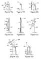
- FIGS. 10 a - care side views of a cutter of a surgical instrument assembly according to another embodiment of the present disclosure.
- FIGS. 11 a - care different views of a cutter of still another embodiment of a surgical instrument assembly according to the present disclosure.
- FIGS. 12 a - bare side views of a cutter of a surgical instrument assembly according to still another embodiment of the present disclosure.
- the lower leg 11 of a patient 10is shown with markings to indicate a fasciotomy treatment for compartment syndrome of a calf muscle according to the present disclosure.
- the proceduremay be performed by making a small incision 24 at an entry location 20 through the patient's skin 12 .
- a surgical instrument assemblydescribed infra, may be moved through incision 24 and under the patient's skin 12 to arrive at a remote location 21 .
- a cutter of the surgical instrument assemblyis maintained in a stowed configuration when being moved from entry location 20 to remote location 21 .
- entry location 20is chosen to be located near one end of a desired fasciotomy incision.
- the remote location 21may be chosen corresponding to the opposite end of the fasciotomy incision.
- the remote location 21 and entry location 20may be reversed as desired by the physician performing the fasciotomy.
- the distance between entry location 20 and remote location 21may roughly correspond to the desired fasciotomy incision length to relieve pressure from the underlying muscle compartment.
- the verb incisemeans to cut in a manner other than scissoring.
- the surgical instrument assemblyis withdrawn from the patient through entry incision 24 .
- the entry incision 24may then be closed or dressed as required by the attending physician.
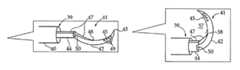
- surgical instrument assembly 39includes a rod 44 defining a longitudinal axis and extending between a handle 53 and a cutter 41 .
- a proximal end of rod 44is coupled to handle 53 , while a distal end is pivotably connected to cutter 41 .
- the cutter 41includes a blade 42 extending axially outward of a distal end of rod 44 , and a pointed tip 43 , which in this embodiment is located at one end of blade 42 .
- pointed tipmeans a protuberance that is sufficiently sharp to pierce fascia.
- Blade 42includes a cutting edge 45 that has an arcuate shape that defines a notch 57 .
- Notch 57may be defined at least in part by blade 42 , when the cutter is in a deployed configuration as shown in FIG. 6 a .
- FIG. 5 ashows cutter 41 in a stowed configuration.
- a deployment wire 47is attached at one end to blade 42 at attachment point 48 , and at its other end to a button 54 slidably attached to the handle 53 as shown in FIG. 6 b .
- the blade 42is attached to rod 44 via a hinge 50 , such that movement of button 54 in the proximal direction as shown in FIG. 6 b causes blade 42 to pivot about hinge 50 to move cutter 41 from the stowed configuration as shown in FIG.
- Attachment point 48is shown to be distal to hinge 50 in FIGS. 5 a and 6 a .
- the vertex 58 of notch 57is defined by blade 42 , so that when the fascia is trapped in notch 57 , the fascia is urged toward vertex 58 to make stable blind incising of the fascia possible.
- Surgical instrument assembly 39may also include a sheath 40 within which rod 44 slides and cutter 41 may be withdrawn when in its stowed configuration to avoid interaction between cutting edge 45 and the patient's tissue while the instrument assembly 39 is being maneuvered from entry location 20 to remote location 21 . Movement of handle 53 relative sheath 40 is communicated to cutter 41 via sliding of a segment of rod 44 within sheath 40 .
- FIGS. 10 a - 10 cshow a surgical instrument assembly according to an alternative embodiment of the present disclosure.
- Instrument assembly 139differs from that previously described in that the blade 142 deforms and straightens when withdrawn into sheath 137 to assume its stowed configuration as shown in FIG. 10 b .
- rod 144is moved in the distal direction relative to sheath 137
- the pointed tip 143 of blade 142emerges from sheath 137 to pierce an initial opening in fascia 114 as shown in FIG. 10 c .
- the blade 142defines a notch 157 within which the fascia may be trapped.
- Blade 142in this embodiment may be made in a hook shape out of a suitable highly flexible material, such as nitinol, and include a cutting edge 145 that defines notch 157 . Also, blade 142 might be sufficiently flexible that it can be straightened for positioning in a stowed configuration within a sheath 137 as shown in FIG. 10 b , but be sufficiently rigid during its deployment and in its deployed configuration that cutter 141 can pierce an initial opening in the fascia 114 as shown in FIG.
- Blade 142may be attachment to rod 144 in any suitable manner, such as via a weld or maybe even a living hinge strategy.
- a surgical instrument assembly 239has a configuration and deployment action that resembles a Park Blade Septostomy Catheter of a type manufactured by Cook, Inc. and sometimes used in interventional cardiology procedures.
- a relatively rigid rod 244which also functions as a deployment wire 247 , slides within a sheath 237 .
- a blade 242is attached to one end of deployment wire 247 at a hinge 252 , and attached at its opposite end to a puncturing component 246 via a hinge 251 .
- Piercing component 246includes a pointed tip 43 at one end, and is attached at its opposite end to sheath 237 via a hinge 250 .
- a hingecan include conventional pinned mechanical hinges, living hinges which rely simply upon a bending of a unitary piece of material, or even a deformation process associated with highly flexible materials such as nitinol.
- the surgical instrument assembly 239assumes a stowed configuration as shown in FIG. 11 b , with puncturing component 246 drawn closer to a portion of sheath 237 covering the cutting edge 245 of blade 242 .
- the cutting edge 245is arranged in parallel with the axis defined by deployment wire 247 , which slides within sheath 237 .
- the blade 242pivots about hinges 251 and 252 along with puncturing component 246 rotating about hinge 250 to move the surgical instrument assembly 239 to its deployed configuration as shown in FIGS. 11 a and 11 c .
- the pointed tip 243may be oriented such that it may pierce the fascia during the deployment maneuver like the previous embodiments, or it may pierce the fascia as the surgical instrument assembly 239 is withdrawn in the proximal direction. After being pierced, the fascia may become trapped in notch 257 , which is defined partly by blade 242 , to perform the remaining steps of the fascia incising procedure.
- a surgical instrument assembly 339according to still another embodiment of the present disclosure is illustrated.
- This embodimentdiffers from the earlier embodiments in that a flexible hook portion 346 is attached at one end to a relatively rigid rod 344 , such as via a solder joint at attachment point 357 .
- Flexible hook portionincludes a pointed tip 343 at its opposite end that facilitates in making an initial entry opening into the fascia to be incised.
- a blade 342has one end attached to an intermediate portion of hook 346 at attachment point 355 , and attached at its opposite end via a hinge 350 to rod 344 .
- hook portion 346 and cutting edge 345 of blade 342define a notch 357 that receives and traps the fascia to be cut in a manner similar to that described previously.
- the cutter 341deforms into the lumen of sheath 337 into a stowed configuration as shown in FIG. 12 b .
- the pointed tip 343may pierce an initial opening into the fascia during the deployment procedure from the stowed configuration as shown in 12 b to the deployed configuration as shown in 12 a .
- the instrument assembly 339is withdrawn in the proximal direction with the fascia trapped in notch 357 adjacent cutting edge 345 to perform the incising step of the compartment syndrome treatment procedure according to the present disclosure.
- FIGS. 1-9the various steps of treating compartment syndrome according to an aspect of the present disclosure are illustrated in a stepwise manner.
- the procedureis initiated by making a relatively short skin incision 24 at an entry location 20 through the patient's skin 12 adjacent the muscle to be treated.
- the entry location 20may not always correspond to the end point for the desired fasciotomy incision 25 .
- a dilatormay or may not be used to enlarge the opening.
- a wire guidemay be advanced into the patient between skin 12 and fascia 14 over the muscle 16 , which is currently experiencing high pressure within the compartment defined by the fascia.
- the wire guide 30may have sufficient rigidity that it can be advanced through the patient's tissue without buckling or kinking, but retains sufficient flexibility that the physician can maneuver the wire guide from the entry location 22 toward the remote location 21 without utilizing a pre-existing body passageway, such as that associated with minimally invasive cardiology procedures known in the art.
- Ultrasound imaging or other strategies known in the artmay be utilized to confirm that the end of the wire 30 is at the desired remote location 21 corresponding to the desired starting point for fascia incision 25 .
- the initial incision 24may be made not only through the patient's skin 12 but also through the fascia 14 such that the wire guide is advanced in the area between fascia 14 and the muscle 16 , without departing from the present disclosure.
- a tapered catheter 31may be advanced over the wire guide.
- a sheath 37may be advanced over the combined wire guide 30 and tapered catheter 31 as best shown in FIG. 4 .
- the end of sheath 37may now be located at or near the remote location 21 .
- the tapered catheter 31 and wire guide 30may be withdrawn.
- the surgical instrument assembly 39which includes its own sheath 40 , is advanced through larger sheath 37 while the cutter 41 of the instrument remains in its stowed configuration as shown in FIG. 4 .
- the surgical instrument assembly 39which includes its own sheath 40 , is advanced through larger sheath 37 while the cutter 41 of the instrument remains in its stowed configuration as shown in FIG. 4 .
- the cutter 41 of the instrumentremains in its stowed configuration as shown in FIG. 4 .
- the cutter 41may be advanced out the end of sheath 40 either by moving rod 44 in the distal direction, or by moving sheath 40 in the proximal direction, or by a combination of both.
- a proper orientationmay ensure that, when cutter 41 is moved from its stowed configuration as shown in FIG. 5 a to its deployed configuration as shown in 6 a , the pointed tip may pierce through to make an initial opening in fascia 14 as shown in FIG. 6 .
- imagingmay require that the rod 44 be rotated to reorient blade 42 properly with regard to fascia 14 before the deployment procedure is executed.
- the cutter 41may be returned to its stowed configuration and the deployment procedure retried after reorienting instrument 39 to better position blade 42 in the proper orientation with regard to fascia 14 .
- the surgical instrument assembly 39is withdrawn in the proximal direction with sheath 37 sliding in the area between uncut skin 12 and uncut fascia 14 while the cutting edge 45 incises the fascia along incision line 25 to relieve pressure in muscle 16 .
- the surgical instrument assembly 39may be reconfigured to its stowed configuration as shown in FIG. 8 by advancing button 54 in the distal direction. This causes deployment wire 47 , which may have sufficient stiffness to avoid buckling, to pivot blade 42 about hinge 50 back to its stowed configuration as shown in FIGS. 5 a and 8 .
- the sheath 44may be advanced over blade 42 as shown in FIG. 9 , and the entire surgical instrument assembly 39 along with sheath 37 may be then withdrawn from the patient through the skin incision opening 24 .
- the relatively small skin incision opening 24may then be closed in a suitable manner or covered with an appropriate dressing, as needed.
- a rodextends between a handle and a cutter, which includes a blade and a pointed tip.
- the cutteris moveable with respect to the rod between a stowed configuration and a deployed configuration.
- the bladedefines at least a portion of a notch when the cutter is in a deployed configuration. Pointed tip and one end of the blade are positioned closer to the rod when in the stowed configuration than when in the deployed configuration.
- a segment of the rodis slidably positioned within a sheath.
- the surgical instrument assemblies according to the present disclosure and the described treatment strategyallow a compartment syndrome fasciotomy procedure to be performed with a relatively small skin incision, but with a full length or long fascia incision. Furthermore, this may be done while reducing trauma to the patient, and in a manner that substantially reduces the risks of post operation infection often associated with the large gaping wounds of fasciotomies according to the prior art. Thus, one might expect a speedier recovery and no necessity for a possible skin graft to cover the wound.
Landscapes
- Health & Medical Sciences (AREA)
- Surgery (AREA)
- Life Sciences & Earth Sciences (AREA)
- Biomedical Technology (AREA)
- Nuclear Medicine, Radiotherapy & Molecular Imaging (AREA)
- Engineering & Computer Science (AREA)
- Orthopedic Medicine & Surgery (AREA)
- Heart & Thoracic Surgery (AREA)
- Medical Informatics (AREA)
- Molecular Biology (AREA)
- Animal Behavior & Ethology (AREA)
- General Health & Medical Sciences (AREA)
- Public Health (AREA)
- Veterinary Medicine (AREA)
- Surgical Instruments (AREA)
Abstract
Description
Claims (5)
Priority Applications (1)
| Application Number | Priority Date | Filing Date | Title |
|---|---|---|---|
| US13/391,451US8840631B2 (en) | 2009-10-29 | 2010-09-28 | Compartment syndrome treatment method and surgical instrument for same |
Applications Claiming Priority (3)
| Application Number | Priority Date | Filing Date | Title |
|---|---|---|---|
| US25598709P | 2009-10-29 | 2009-10-29 | |
| US13/391,451US8840631B2 (en) | 2009-10-29 | 2010-09-28 | Compartment syndrome treatment method and surgical instrument for same |
| PCT/US2010/050473WO2011053422A1 (en) | 2009-10-29 | 2010-09-28 | Compartment syndrome treatment method and surgical instrument for same |
Publications (2)
| Publication Number | Publication Date |
|---|---|
| US20120150208A1 US20120150208A1 (en) | 2012-06-14 |
| US8840631B2true US8840631B2 (en) | 2014-09-23 |
Family
ID=43379030
Family Applications (1)
| Application Number | Title | Priority Date | Filing Date |
|---|---|---|---|
| US13/391,451Expired - Fee RelatedUS8840631B2 (en) | 2009-10-29 | 2010-09-28 | Compartment syndrome treatment method and surgical instrument for same |
Country Status (3)
| Country | Link |
|---|---|
| US (1) | US8840631B2 (en) |
| EP (1) | EP2493399A1 (en) |
| WO (1) | WO2011053422A1 (en) |
Cited By (5)
| Publication number | Priority date | Publication date | Assignee | Title |
|---|---|---|---|---|
| US20170238958A1 (en)* | 2016-02-24 | 2017-08-24 | Ira Lown | Carpal Tunnel Release Systems and Methods |
| US9833321B2 (en) | 2016-04-25 | 2017-12-05 | Imds Llc | Joint fusion instrumentation and methods |
| US10045803B2 (en) | 2014-07-03 | 2018-08-14 | Mayo Foundation For Medical Education And Research | Sacroiliac joint fusion screw and method |
| US10413332B2 (en) | 2016-04-25 | 2019-09-17 | Imds Llc | Joint fusion implant and methods |
| US12150670B1 (en)* | 2023-08-31 | 2024-11-26 | Li Li | Pet intraurethral incision knife |
Families Citing this family (10)
| Publication number | Priority date | Publication date | Assignee | Title |
|---|---|---|---|---|
| US9402644B2 (en)* | 2013-03-13 | 2016-08-02 | Covidien Lp | Reverse seam ripper dissector |
| US20160038168A1 (en)* | 2014-08-11 | 2016-02-11 | Covidien Lp | Surgical forceps and methods of manufacturing the same |
| CN104546070B (en)* | 2015-01-07 | 2017-02-22 | 杜学军 | Skin incising and suturing device |
| US11291466B2 (en)* | 2015-08-10 | 2022-04-05 | Indiana University Research And Technology Corporation | Device and method for scar subcision |
| EP3586776A1 (en)* | 2018-06-29 | 2020-01-01 | Swibrace SA | Medical instrument for percutaneous release procedures |
| WO2020023412A1 (en) | 2018-07-23 | 2020-01-30 | Nc8, Inc. | Cellulite treatment system and methods |
| MX2021000901A (en) | 2018-07-23 | 2021-06-18 | Revelle Aesthetics Inc | Cellulite treatment system and methods. |
| US11980388B2 (en) | 2018-07-23 | 2024-05-14 | Revelle Aesthetics, Inc. | Cellulite treatment apparatus |
| US20230255678A1 (en)* | 2018-07-23 | 2023-08-17 | Revelle Aesthetics, Inc. | Aesthetic treatment systems and methods |
| EP4176831A1 (en) | 2021-11-07 | 2023-05-10 | Spirecut Sa | Medical instrument, in particular for percutaneous surgical/medical procedures |
Citations (21)
| Publication number | Priority date | Publication date | Assignee | Title |
|---|---|---|---|---|
| US2691370A (en)* | 1952-03-27 | 1954-10-12 | American Cystoscope Makers Inc | Instrument for heart surgery |
| US4963147A (en)* | 1987-09-18 | 1990-10-16 | John M. Agee | Surgical instrument |
| US5053044A (en) | 1988-01-11 | 1991-10-01 | Devices For Vascular Intervention, Inc. | Catheter and method for making intravascular incisions |
| US5112346A (en)* | 1989-06-08 | 1992-05-12 | Richard Wolf Gmbh | Retrograde cutting hook punch |
| DE4140402A1 (en) | 1991-12-07 | 1993-06-09 | Dieter Prof. Dr.Med. 7700 Singen De Ruehland | Instrument for surgical intervention in stomach cavity - has sleeve tube for at least one axially movable rod with blade at operation end of instrument being controlled by rod |
| US5578051A (en) | 1992-12-07 | 1996-11-26 | Theodor Esser And Eugene T. King | Endoscopic surgical procedure and instrument for implementation thereof |
| WO1996037157A1 (en) | 1995-05-26 | 1996-11-28 | Levin John M | Fasciotome |
| US5584842A (en)* | 1992-12-02 | 1996-12-17 | Intramed Laboratories, Inc. | Valvulotome and method of using |
| US5620446A (en) | 1992-07-14 | 1997-04-15 | Endoscopic Heel Systems, Inc. | Surgical apparatus for performing endoscopic surgery at locations where tissue inserts into bone |
| US5720754A (en) | 1989-08-16 | 1998-02-24 | Medtronic, Inc. | Device or apparatus for manipulating matter |
| US5797906A (en) | 1993-11-24 | 1998-08-25 | Valleylab Inc | Retrograde tissue splitter and method |
| US6051005A (en) | 1997-09-26 | 2000-04-18 | Brandsey; Edward P. | Laparoscopic knife |
| US20040098005A1 (en) | 2002-11-18 | 2004-05-20 | A.M. Surgical, Inc. | Endoscopic surgical procedure |
| US20050137448A1 (en)* | 2003-12-19 | 2005-06-23 | Vance Products Incorporated, D/B/A Cook Urological Incorporated And Sabin Corporation | Catheter with snap on feature |
| US20050251161A1 (en) | 2004-05-07 | 2005-11-10 | Usgi Medical Inc. | Needle assembly for tissue manipulation |
| US20060241665A1 (en) | 2005-04-08 | 2006-10-26 | Vance Products Incorporated, D/B/A Cook Urological Incorporated | Percutaneous and endoscopic cutters |
| US20070225740A1 (en)* | 2006-02-22 | 2007-09-27 | Loubert Suddaby | Endoscopic Pulley Knife Instrument for Transecting Ligaments or Fascia |
| WO2008028701A1 (en) | 2006-09-08 | 2008-03-13 | Ethicon Endo-Surgery, Inc. | A surgical instrument for performing controlled myotomies |
| US20080221579A1 (en)* | 2007-02-13 | 2008-09-11 | The Board Of Regents Of The University Of Texas System | Apparatus to trace and cut a tendon or other laterally extended anatomical structure |
| US20090182192A1 (en)* | 2008-01-14 | 2009-07-16 | Olympus Medical Systems Corp. | Treating tool for endoscope |
| US20090187203A1 (en)* | 1999-08-19 | 2009-07-23 | Fox Hollow Technologies, Inc. | Apparatus and methods for material capture and removal |
- 2010
- 2010-09-28WOPCT/US2010/050473patent/WO2011053422A1/enactiveApplication Filing
- 2010-09-28USUS13/391,451patent/US8840631B2/ennot_activeExpired - Fee Related
- 2010-09-28EPEP10766171Apatent/EP2493399A1/ennot_activeWithdrawn
Patent Citations (21)
| Publication number | Priority date | Publication date | Assignee | Title |
|---|---|---|---|---|
| US2691370A (en)* | 1952-03-27 | 1954-10-12 | American Cystoscope Makers Inc | Instrument for heart surgery |
| US4963147A (en)* | 1987-09-18 | 1990-10-16 | John M. Agee | Surgical instrument |
| US5053044A (en) | 1988-01-11 | 1991-10-01 | Devices For Vascular Intervention, Inc. | Catheter and method for making intravascular incisions |
| US5112346A (en)* | 1989-06-08 | 1992-05-12 | Richard Wolf Gmbh | Retrograde cutting hook punch |
| US5720754A (en) | 1989-08-16 | 1998-02-24 | Medtronic, Inc. | Device or apparatus for manipulating matter |
| DE4140402A1 (en) | 1991-12-07 | 1993-06-09 | Dieter Prof. Dr.Med. 7700 Singen De Ruehland | Instrument for surgical intervention in stomach cavity - has sleeve tube for at least one axially movable rod with blade at operation end of instrument being controlled by rod |
| US5620446A (en) | 1992-07-14 | 1997-04-15 | Endoscopic Heel Systems, Inc. | Surgical apparatus for performing endoscopic surgery at locations where tissue inserts into bone |
| US5584842A (en)* | 1992-12-02 | 1996-12-17 | Intramed Laboratories, Inc. | Valvulotome and method of using |
| US5578051A (en) | 1992-12-07 | 1996-11-26 | Theodor Esser And Eugene T. King | Endoscopic surgical procedure and instrument for implementation thereof |
| US5797906A (en) | 1993-11-24 | 1998-08-25 | Valleylab Inc | Retrograde tissue splitter and method |
| WO1996037157A1 (en) | 1995-05-26 | 1996-11-28 | Levin John M | Fasciotome |
| US6051005A (en) | 1997-09-26 | 2000-04-18 | Brandsey; Edward P. | Laparoscopic knife |
| US20090187203A1 (en)* | 1999-08-19 | 2009-07-23 | Fox Hollow Technologies, Inc. | Apparatus and methods for material capture and removal |
| US20040098005A1 (en) | 2002-11-18 | 2004-05-20 | A.M. Surgical, Inc. | Endoscopic surgical procedure |
| US20050137448A1 (en)* | 2003-12-19 | 2005-06-23 | Vance Products Incorporated, D/B/A Cook Urological Incorporated And Sabin Corporation | Catheter with snap on feature |
| US20050251161A1 (en) | 2004-05-07 | 2005-11-10 | Usgi Medical Inc. | Needle assembly for tissue manipulation |
| US20060241665A1 (en) | 2005-04-08 | 2006-10-26 | Vance Products Incorporated, D/B/A Cook Urological Incorporated | Percutaneous and endoscopic cutters |
| US20070225740A1 (en)* | 2006-02-22 | 2007-09-27 | Loubert Suddaby | Endoscopic Pulley Knife Instrument for Transecting Ligaments or Fascia |
| WO2008028701A1 (en) | 2006-09-08 | 2008-03-13 | Ethicon Endo-Surgery, Inc. | A surgical instrument for performing controlled myotomies |
| US20080221579A1 (en)* | 2007-02-13 | 2008-09-11 | The Board Of Regents Of The University Of Texas System | Apparatus to trace and cut a tendon or other laterally extended anatomical structure |
| US20090182192A1 (en)* | 2008-01-14 | 2009-07-16 | Olympus Medical Systems Corp. | Treating tool for endoscope |
Cited By (13)
| Publication number | Priority date | Publication date | Assignee | Title |
|---|---|---|---|---|
| US11357557B2 (en) | 2014-07-03 | 2022-06-14 | Mayo Foundation For Medical Education And Research | Bone joint reaming tool |
| US10045803B2 (en) | 2014-07-03 | 2018-08-14 | Mayo Foundation For Medical Education And Research | Sacroiliac joint fusion screw and method |
| US11974769B2 (en) | 2016-02-24 | 2024-05-07 | Edge Instruments, Llc | Carpal tunnel release systems and methods |
| US20170238958A1 (en)* | 2016-02-24 | 2017-08-24 | Ira Lown | Carpal Tunnel Release Systems and Methods |
| US10499942B2 (en)* | 2016-02-24 | 2019-12-10 | Ira Lown | Carpal tunnel release systems and methods |
| US11357531B2 (en) | 2016-02-24 | 2022-06-14 | Edge Instruments, Llc | Carpal tunnel release systems and methods |
| US10413332B2 (en) | 2016-04-25 | 2019-09-17 | Imds Llc | Joint fusion implant and methods |
| US10751071B2 (en) | 2016-04-25 | 2020-08-25 | Imds Llc | Joint fusion instrumentation and methods |
| US11129649B2 (en) | 2016-04-25 | 2021-09-28 | Imds Llc | Joint fusion implant and methods |
| US10610244B2 (en) | 2016-04-25 | 2020-04-07 | Imds Llc | Joint fusion instrumentation and methods |
| US10603177B2 (en) | 2016-04-25 | 2020-03-31 | Imds Llc | Joint fusion instrumentation and methods |
| US9833321B2 (en) | 2016-04-25 | 2017-12-05 | Imds Llc | Joint fusion instrumentation and methods |
| US12150670B1 (en)* | 2023-08-31 | 2024-11-26 | Li Li | Pet intraurethral incision knife |
Also Published As
| Publication number | Publication date |
|---|---|
| EP2493399A1 (en) | 2012-09-05 |
| US20120150208A1 (en) | 2012-06-14 |
| WO2011053422A1 (en) | 2011-05-05 |
Similar Documents
| Publication | Publication Date | Title |
|---|---|---|
| US8840631B2 (en) | Compartment syndrome treatment method and surgical instrument for same | |
| US20220323094A1 (en) | Method and septostomy device for creating an interatrial aperture | |
| US20190374254A1 (en) | Transcatheter device for interatrial anastomosis | |
| EP1253859B1 (en) | Apparatus for creating a channel between adjacent body lumens | |
| WO2021091566A1 (en) | Method and septostomy device for creating an interatrial aperture | |
| US20180028213A1 (en) | Unitary Endoscopic Vessel Harvesting Devices | |
| JP5695564B2 (en) | Tissue access site system and method | |
| US20080215072A1 (en) | Methods and apparatus for utilization of barbed sutures in human tissue including a method for eliminating or improving blood flow in veins | |
| US20050283193A1 (en) | Introducer guide | |
| US12035905B2 (en) | Vessel closure devices and methods | |
| EP3087927B1 (en) | Unitary endoscopic vessel harvesting devices with an elastic force | |
| EP3451940A1 (en) | Vascular access devices, systems, and methods | |
| US20200246042A1 (en) | Catheter comprising a cutting element | |
| WO2018213626A1 (en) | Single catheter electrode tissue cutting system for creating anastomoses | |
| CN107981917B (en) | Tubular cutter for minimally invasive human vein graft acquisition | |
| GB2487527A (en) | Needle and curved catheter | |
| WO2008027366A2 (en) | Devices and methods for creating and closing controlled openings in tissue | |
| EP1146820B1 (en) | Device for stripping veins | |
| US20240374892A1 (en) | Directable Tunnel Device for Subcutaneous Implantable Cardio Defibrillator | |
| CN111685805B (en) | Cutter device | |
| CN111685804B (en) | Channel device | |
| CN111685806B (en) | Control device |
Legal Events
| Date | Code | Title | Description |
|---|---|---|---|
| AS | Assignment | Owner name:COOK INCORPORATED, INDIANA Free format text:ASSIGNMENT OF ASSIGNORS INTEREST;ASSIGNOR:MESSMER, SARAH;REEL/FRAME:025050/0799 Effective date:20100924 | |
| AS | Assignment | Owner name:COOK MEDICAL TECHNOLOGIES LLC, INDIANA Free format text:ASSIGNMENT OF ASSIGNORS INTEREST;ASSIGNOR:COOK INCORPORATED;REEL/FRAME:027708/0735 Effective date:20120213 | |
| STCF | Information on status: patent grant | Free format text:PATENTED CASE | |
| MAFP | Maintenance fee payment | Free format text:PAYMENT OF MAINTENANCE FEE, 4TH YEAR, LARGE ENTITY (ORIGINAL EVENT CODE: M1551) Year of fee payment:4 | |
| FEPP | Fee payment procedure | Free format text:MAINTENANCE FEE REMINDER MAILED (ORIGINAL EVENT CODE: REM.); ENTITY STATUS OF PATENT OWNER: LARGE ENTITY | |
| LAPS | Lapse for failure to pay maintenance fees | Free format text:PATENT EXPIRED FOR FAILURE TO PAY MAINTENANCE FEES (ORIGINAL EVENT CODE: EXP.); ENTITY STATUS OF PATENT OWNER: LARGE ENTITY | |
| STCH | Information on status: patent discontinuation | Free format text:PATENT EXPIRED DUE TO NONPAYMENT OF MAINTENANCE FEES UNDER 37 CFR 1.362 | |
| FP | Lapsed due to failure to pay maintenance fee | Effective date:20220923 |