US8840466B2 - Method and system to create three-dimensional mapping in a two-dimensional game - Google Patents
Method and system to create three-dimensional mapping in a two-dimensional gameDownload PDFInfo
- Publication number
- US8840466B2 US8840466B2US13/506,474US201213506474AUS8840466B2US 8840466 B2US8840466 B2US 8840466B2US 201213506474 AUS201213506474 AUS 201213506474AUS 8840466 B2US8840466 B2US 8840466B2
- Authority
- US
- United States
- Prior art keywords
- game
- player
- dimensional
- world
- display
- Prior art date
- Legal status (The legal status is an assumption and is not a legal conclusion. Google has not performed a legal analysis and makes no representation as to the accuracy of the status listed.)
- Active, expires
Links
- 238000013507mappingMethods0.000titleclaimsabstractdescription14
- 238000000034methodMethods0.000titledescription49
- 230000003993interactionEffects0.000claimsabstractdescription18
- 230000008447perceptionEffects0.000claimsabstractdescription3
- 230000033001locomotionEffects0.000claimsdescription29
- 230000003287optical effectEffects0.000claimsdescription23
- 238000003384imaging methodMethods0.000claimsdescription2
- 230000009466transformationEffects0.000description15
- 238000013519translationMethods0.000description9
- 230000014616translationEffects0.000description9
- 238000012545processingMethods0.000description8
- 238000009877renderingMethods0.000description8
- 210000003128headAnatomy0.000description7
- 241000282887SuidaeSpecies0.000description6
- 238000005259measurementMethods0.000description6
- 230000007246mechanismEffects0.000description6
- 238000005516engineering processMethods0.000description5
- 230000006870functionEffects0.000description5
- 230000008859changeEffects0.000description4
- 239000011521glassSubstances0.000description4
- 240000000136Scabiosa atropurpureaSpecies0.000description3
- 230000008901benefitEffects0.000description3
- 230000000694effectsEffects0.000description3
- 238000000844transformationMethods0.000description3
- 230000000007visual effectEffects0.000description3
- 230000001133accelerationEffects0.000description2
- 230000009471actionEffects0.000description2
- 238000001514detection methodMethods0.000description2
- 230000004048modificationEffects0.000description2
- 238000012986modificationMethods0.000description2
- 230000004044responseEffects0.000description2
- 230000003595spectral effectEffects0.000description2
- 238000003860storageMethods0.000description2
- 235000015842HesperisNutrition0.000description1
- 235000012633Iberis amaraNutrition0.000description1
- 241000699666Mus <mouse, genus>Species0.000description1
- 241000699670Mus sp.Species0.000description1
- 241000577979Peromyscus spicilegusSpecies0.000description1
- 244000208734Pisonia aculeataSpecies0.000description1
- 239000008186active pharmaceutical agentSubstances0.000description1
- 238000013459approachMethods0.000description1
- 238000010420art techniqueMethods0.000description1
- 238000005266castingMethods0.000description1
- 238000010276constructionMethods0.000description1
- 238000010586diagramMethods0.000description1
- 230000002708enhancing effectEffects0.000description1
- 230000004438eyesightEffects0.000description1
- 230000001815facial effectEffects0.000description1
- 238000010304firingMethods0.000description1
- 230000005484gravityEffects0.000description1
- 244000144980herdSpecies0.000description1
- 230000010354integrationEffects0.000description1
- 238000004519manufacturing processMethods0.000description1
- 239000011159matrix materialSubstances0.000description1
- 230000006386memory functionEffects0.000description1
- 230000010363phase shiftEffects0.000description1
- 230000008569processEffects0.000description1
- 230000035945sensitivityEffects0.000description1
- 238000001228spectrumMethods0.000description1
- 239000004575stoneSubstances0.000description1
- 230000008685targetingEffects0.000description1
- 230000036962time dependentEffects0.000description1
Images


Classifications
- A—HUMAN NECESSITIES
- A63—SPORTS; GAMES; AMUSEMENTS
- A63F—CARD, BOARD, OR ROULETTE GAMES; INDOOR GAMES USING SMALL MOVING PLAYING BODIES; VIDEO GAMES; GAMES NOT OTHERWISE PROVIDED FOR
- A63F13/00—Video games, i.e. games using an electronically generated display having two or more dimensions
- A63F13/20—Input arrangements for video game devices
- A63F13/22—Setup operations, e.g. calibration, key configuration or button assignment
- A63F13/10—
- A—HUMAN NECESSITIES
- A63—SPORTS; GAMES; AMUSEMENTS
- A63F—CARD, BOARD, OR ROULETTE GAMES; INDOOR GAMES USING SMALL MOVING PLAYING BODIES; VIDEO GAMES; GAMES NOT OTHERWISE PROVIDED FOR
- A63F13/00—Video games, i.e. games using an electronically generated display having two or more dimensions
- A63F13/40—Processing input control signals of video game devices, e.g. signals generated by the player or derived from the environment
- A63F13/42—Processing input control signals of video game devices, e.g. signals generated by the player or derived from the environment by mapping the input signals into game commands, e.g. mapping the displacement of a stylus on a touch screen to the steering angle of a virtual vehicle
- A—HUMAN NECESSITIES
- A63—SPORTS; GAMES; AMUSEMENTS
- A63F—CARD, BOARD, OR ROULETTE GAMES; INDOOR GAMES USING SMALL MOVING PLAYING BODIES; VIDEO GAMES; GAMES NOT OTHERWISE PROVIDED FOR
- A63F13/00—Video games, i.e. games using an electronically generated display having two or more dimensions
- A63F13/40—Processing input control signals of video game devices, e.g. signals generated by the player or derived from the environment
- A63F13/44—Processing input control signals of video game devices, e.g. signals generated by the player or derived from the environment involving timing of operations, e.g. performing an action within a time slot
- A—HUMAN NECESSITIES
- A63—SPORTS; GAMES; AMUSEMENTS
- A63F—CARD, BOARD, OR ROULETTE GAMES; INDOOR GAMES USING SMALL MOVING PLAYING BODIES; VIDEO GAMES; GAMES NOT OTHERWISE PROVIDED FOR
- A63F13/00—Video games, i.e. games using an electronically generated display having two or more dimensions
- A63F13/50—Controlling the output signals based on the game progress
- A63F13/52—Controlling the output signals based on the game progress involving aspects of the displayed game scene
- A—HUMAN NECESSITIES
- A63—SPORTS; GAMES; AMUSEMENTS
- A63F—CARD, BOARD, OR ROULETTE GAMES; INDOOR GAMES USING SMALL MOVING PLAYING BODIES; VIDEO GAMES; GAMES NOT OTHERWISE PROVIDED FOR
- A63F13/00—Video games, i.e. games using an electronically generated display having two or more dimensions
- A63F13/55—Controlling game characters or game objects based on the game progress
- A63F13/56—Computing the motion of game characters with respect to other game characters, game objects or elements of the game scene, e.g. for simulating the behaviour of a group of virtual soldiers or for path finding
- A—HUMAN NECESSITIES
- A63—SPORTS; GAMES; AMUSEMENTS
- A63F—CARD, BOARD, OR ROULETTE GAMES; INDOOR GAMES USING SMALL MOVING PLAYING BODIES; VIDEO GAMES; GAMES NOT OTHERWISE PROVIDED FOR
- A63F13/00—Video games, i.e. games using an electronically generated display having two or more dimensions
- A63F13/55—Controlling game characters or game objects based on the game progress
- A63F13/57—Simulating properties, behaviour or motion of objects in the game world, e.g. computing tyre load in a car race game
- A63F13/573—Simulating properties, behaviour or motion of objects in the game world, e.g. computing tyre load in a car race game using trajectories of game objects, e.g. of a golf ball according to the point of impact
- A—HUMAN NECESSITIES
- A63—SPORTS; GAMES; AMUSEMENTS
- A63F—CARD, BOARD, OR ROULETTE GAMES; INDOOR GAMES USING SMALL MOVING PLAYING BODIES; VIDEO GAMES; GAMES NOT OTHERWISE PROVIDED FOR
- A63F13/00—Video games, i.e. games using an electronically generated display having two or more dimensions
- A63F13/20—Input arrangements for video game devices
- A63F13/21—Input arrangements for video game devices characterised by their sensors, purposes or types
- A63F13/211—Input arrangements for video game devices characterised by their sensors, purposes or types using inertial sensors, e.g. accelerometers or gyroscopes
- A—HUMAN NECESSITIES
- A63—SPORTS; GAMES; AMUSEMENTS
- A63F—CARD, BOARD, OR ROULETTE GAMES; INDOOR GAMES USING SMALL MOVING PLAYING BODIES; VIDEO GAMES; GAMES NOT OTHERWISE PROVIDED FOR
- A63F13/00—Video games, i.e. games using an electronically generated display having two or more dimensions
- A63F13/20—Input arrangements for video game devices
- A63F13/21—Input arrangements for video game devices characterised by their sensors, purposes or types
- A63F13/213—Input arrangements for video game devices characterised by their sensors, purposes or types comprising photodetecting means, e.g. cameras, photodiodes or infrared cells
- A—HUMAN NECESSITIES
- A63—SPORTS; GAMES; AMUSEMENTS
- A63F—CARD, BOARD, OR ROULETTE GAMES; INDOOR GAMES USING SMALL MOVING PLAYING BODIES; VIDEO GAMES; GAMES NOT OTHERWISE PROVIDED FOR
- A63F13/00—Video games, i.e. games using an electronically generated display having two or more dimensions
- A63F13/20—Input arrangements for video game devices
- A63F13/21—Input arrangements for video game devices characterised by their sensors, purposes or types
- A63F13/214—Input arrangements for video game devices characterised by their sensors, purposes or types for locating contacts on a surface, e.g. floor mats or touch pads
- A63F13/2145—Input arrangements for video game devices characterised by their sensors, purposes or types for locating contacts on a surface, e.g. floor mats or touch pads the surface being also a display device, e.g. touch screens
- A—HUMAN NECESSITIES
- A63—SPORTS; GAMES; AMUSEMENTS
- A63F—CARD, BOARD, OR ROULETTE GAMES; INDOOR GAMES USING SMALL MOVING PLAYING BODIES; VIDEO GAMES; GAMES NOT OTHERWISE PROVIDED FOR
- A63F13/00—Video games, i.e. games using an electronically generated display having two or more dimensions
- A63F13/40—Processing input control signals of video game devices, e.g. signals generated by the player or derived from the environment
- A63F13/42—Processing input control signals of video game devices, e.g. signals generated by the player or derived from the environment by mapping the input signals into game commands, e.g. mapping the displacement of a stylus on a touch screen to the steering angle of a virtual vehicle
- A63F13/428—Processing input control signals of video game devices, e.g. signals generated by the player or derived from the environment by mapping the input signals into game commands, e.g. mapping the displacement of a stylus on a touch screen to the steering angle of a virtual vehicle involving motion or position input signals, e.g. signals representing the rotation of an input controller or a player's arm motions sensed by accelerometers or gyroscopes
- A—HUMAN NECESSITIES
- A63—SPORTS; GAMES; AMUSEMENTS
- A63F—CARD, BOARD, OR ROULETTE GAMES; INDOOR GAMES USING SMALL MOVING PLAYING BODIES; VIDEO GAMES; GAMES NOT OTHERWISE PROVIDED FOR
- A63F13/00—Video games, i.e. games using an electronically generated display having two or more dimensions
- A63F13/60—Generating or modifying game content before or while executing the game program, e.g. authoring tools specially adapted for game development or game-integrated level editor
- A63F13/65—Generating or modifying game content before or while executing the game program, e.g. authoring tools specially adapted for game development or game-integrated level editor automatically by game devices or servers from real world data, e.g. measurement in live racing competition
- A—HUMAN NECESSITIES
- A63—SPORTS; GAMES; AMUSEMENTS
- A63F—CARD, BOARD, OR ROULETTE GAMES; INDOOR GAMES USING SMALL MOVING PLAYING BODIES; VIDEO GAMES; GAMES NOT OTHERWISE PROVIDED FOR
- A63F13/00—Video games, i.e. games using an electronically generated display having two or more dimensions
- A63F13/80—Special adaptations for executing a specific game genre or game mode
- A63F13/837—Shooting of targets
- A—HUMAN NECESSITIES
- A63—SPORTS; GAMES; AMUSEMENTS
- A63F—CARD, BOARD, OR ROULETTE GAMES; INDOOR GAMES USING SMALL MOVING PLAYING BODIES; VIDEO GAMES; GAMES NOT OTHERWISE PROVIDED FOR
- A63F13/00—Video games, i.e. games using an electronically generated display having two or more dimensions
- A63F13/90—Constructional details or arrangements of video game devices not provided for in groups A63F13/20 or A63F13/25, e.g. housing, wiring, connections or cabinets
- A63F13/92—Video game devices specially adapted to be hand-held while playing
- A—HUMAN NECESSITIES
- A63—SPORTS; GAMES; AMUSEMENTS
- A63F—CARD, BOARD, OR ROULETTE GAMES; INDOOR GAMES USING SMALL MOVING PLAYING BODIES; VIDEO GAMES; GAMES NOT OTHERWISE PROVIDED FOR
- A63F2300/00—Features of games using an electronically generated display having two or more dimensions, e.g. on a television screen, showing representations related to the game
- A63F2300/10—Features of games using an electronically generated display having two or more dimensions, e.g. on a television screen, showing representations related to the game characterized by input arrangements for converting player-generated signals into game device control signals
- A63F2300/105—Features of games using an electronically generated display having two or more dimensions, e.g. on a television screen, showing representations related to the game characterized by input arrangements for converting player-generated signals into game device control signals using inertial sensors, e.g. accelerometers, gyroscopes
- A—HUMAN NECESSITIES
- A63—SPORTS; GAMES; AMUSEMENTS
- A63F—CARD, BOARD, OR ROULETTE GAMES; INDOOR GAMES USING SMALL MOVING PLAYING BODIES; VIDEO GAMES; GAMES NOT OTHERWISE PROVIDED FOR
- A63F2300/00—Features of games using an electronically generated display having two or more dimensions, e.g. on a television screen, showing representations related to the game
- A63F2300/10—Features of games using an electronically generated display having two or more dimensions, e.g. on a television screen, showing representations related to the game characterized by input arrangements for converting player-generated signals into game device control signals
- A63F2300/1068—Features of games using an electronically generated display having two or more dimensions, e.g. on a television screen, showing representations related to the game characterized by input arrangements for converting player-generated signals into game device control signals being specially adapted to detect the point of contact of the player on a surface, e.g. floor mat, touch pad
- A63F2300/1075—Features of games using an electronically generated display having two or more dimensions, e.g. on a television screen, showing representations related to the game characterized by input arrangements for converting player-generated signals into game device control signals being specially adapted to detect the point of contact of the player on a surface, e.g. floor mat, touch pad using a touch screen
- A—HUMAN NECESSITIES
- A63—SPORTS; GAMES; AMUSEMENTS
- A63F—CARD, BOARD, OR ROULETTE GAMES; INDOOR GAMES USING SMALL MOVING PLAYING BODIES; VIDEO GAMES; GAMES NOT OTHERWISE PROVIDED FOR
- A63F2300/00—Features of games using an electronically generated display having two or more dimensions, e.g. on a television screen, showing representations related to the game
- A63F2300/10—Features of games using an electronically generated display having two or more dimensions, e.g. on a television screen, showing representations related to the game characterized by input arrangements for converting player-generated signals into game device control signals
- A63F2300/1087—Features of games using an electronically generated display having two or more dimensions, e.g. on a television screen, showing representations related to the game characterized by input arrangements for converting player-generated signals into game device control signals comprising photodetecting means, e.g. a camera
- A63F2300/1093—Features of games using an electronically generated display having two or more dimensions, e.g. on a television screen, showing representations related to the game characterized by input arrangements for converting player-generated signals into game device control signals comprising photodetecting means, e.g. a camera using visible light
- A—HUMAN NECESSITIES
- A63—SPORTS; GAMES; AMUSEMENTS
- A63F—CARD, BOARD, OR ROULETTE GAMES; INDOOR GAMES USING SMALL MOVING PLAYING BODIES; VIDEO GAMES; GAMES NOT OTHERWISE PROVIDED FOR
- A63F2300/00—Features of games using an electronically generated display having two or more dimensions, e.g. on a television screen, showing representations related to the game
- A63F2300/20—Features of games using an electronically generated display having two or more dimensions, e.g. on a television screen, showing representations related to the game characterised by details of the game platform
- A63F2300/204—Features of games using an electronically generated display having two or more dimensions, e.g. on a television screen, showing representations related to the game characterised by details of the game platform the platform being a handheld device
- A—HUMAN NECESSITIES
- A63—SPORTS; GAMES; AMUSEMENTS
- A63F—CARD, BOARD, OR ROULETTE GAMES; INDOOR GAMES USING SMALL MOVING PLAYING BODIES; VIDEO GAMES; GAMES NOT OTHERWISE PROVIDED FOR
- A63F2300/00—Features of games using an electronically generated display having two or more dimensions, e.g. on a television screen, showing representations related to the game
- A63F2300/60—Methods for processing data by generating or executing the game program
- A63F2300/6045—Methods for processing data by generating or executing the game program for mapping control signals received from the input arrangement into game commands
- A—HUMAN NECESSITIES
- A63—SPORTS; GAMES; AMUSEMENTS
- A63F—CARD, BOARD, OR ROULETTE GAMES; INDOOR GAMES USING SMALL MOVING PLAYING BODIES; VIDEO GAMES; GAMES NOT OTHERWISE PROVIDED FOR
- A63F2300/00—Features of games using an electronically generated display having two or more dimensions, e.g. on a television screen, showing representations related to the game
- A63F2300/60—Methods for processing data by generating or executing the game program
- A63F2300/64—Methods for processing data by generating or executing the game program for computing dynamical parameters of game objects, e.g. motion determination or computation of frictional forces for a virtual car
- A63F2300/646—Methods for processing data by generating or executing the game program for computing dynamical parameters of game objects, e.g. motion determination or computation of frictional forces for a virtual car for calculating the trajectory of an object
Definitions
- the inventionrelates generally to creating a three-dimensional ordering of objects in a two-dimensional game application.
- a first class of two-dimensional game applicationshas an (x, y, z) coordinate system, responsive to at least real-world two-dimensional (x w ,y w ) input from a game player.
- a second classis similar to the first class but can respond to real-world three-dimensional (x w , y w , z w ) input from a game player.
- a third class of two-dimensional game applicationshas only an (x,y) coordinate system, responsive to real-world two-dimensional (x w ,y w ) input from a game player, and the resultant game display video rendering, unless modified, lacks a sense of depth distance.
- aspects of the present inventioncan enhance realism for the game player, especially for the first two classes of two-dimensional game applications, and can also enhance realism for the game player if the third class of game applications is modified to work with the invention.
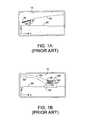
- FIGS. 1A-1CChallenges associated with inputting three-dimensional commands to a two-dimensional application, typically a video game, will be described generally with respect to FIGS. 1A-1C .
- the popular mode of this game applicationfalls into the third class of applications, as defined above. In its simplest form, the user or player aims and fires a virtual slingshot depicted on the game display.
- the goalis to accurately lob a projectile (an angry bird) from the slingshot towards the target, a rickety structure providing shelter to a herd of pigs. Points are awarded in the game for destroying the shelter and dispatching the pigs by accurately controlling the slingshot and its projectile. It is understood that in this game application, player input and display output are each two-dimensional.
- FIG. 1Adepicts an aiming scene in the Angry Birds game as it might appear to a user (or player) on display 10 of a monitor associated with the game-playing device.
- the deviceis perhaps a hand-held smart phone that executes the AngryBirds game application and includes the display as an integral part of the device.
- a slingshot 20 with elastic band 30holds a projectile 40 that is to be launched upon a desired trajectory 50 ′ (see FIG. 1B ) by the game player to hit the target (the pig shelter 60 and pigs 70 , shown in FIG. 1B ).
- the gameshows the last used trajectory 50 to aid the player and making adjustments to arrive at a new trajectory 50 ′, and also shows the ground terrain 80 .
- virtual projectile 40can be moved left or right (x-direction) and/or up or down (y-direction), but cannot move into or out of the plane of display 10 , which is why no z-axis is depicted. Understandably launching projectile 40 requires the user to cause slingshot 20 to direct a vector force accurately towards the desired target upon a successful trajectory 50 ′.
- a true vector forceis required in that the quantum of force imparted to projectile 40 must be sufficient to reach the target, and the aiming of the projectile must be accurate enough to hit the target.
- FIGS. 1A and 1Bdepict the target aspect of the game and shows that a higher trajectory 50 ′ was successfully achieved, with the desired result that projectile 40 has hit a portion of structure 60 . At least a portion of structure 60 will collapse injuring at least one pig 70 , sheltering within the structure, and appropriate game points will be awarded. Note that the display in FIGS. 1A and 1B has no notion of depth, as might be seen from the perspective of the game player. As such projectile 40 cannot be aimed at a target 60 ′ “in front of” structure 60 , or a target 60 ′′ “behind” target 60 because there is simply no sense of depth z in this class three two-dimensional game application.
- Some game device manufacturestry to promote a sense of three-dimensionality in the display itself. Some game devices might produce a three-dimensional display requiring the player to wear stereoscopic glasses, or perhaps the display will be auto-stereoscopic, which would not require eye glasses to be worn by the player.
- the Nintendo ⁇ 3DS ⁇ mobile game deviceuses an auto-stereoscopic display to promote a three-dimensional experience, although the user interface still requires buttons and physical touching.
- a two-dimensional game applicationbe class one, class two, or class three
- Further such method and systemshould enable the two-dimensional game application to convert to an integrated three-dimensional input and output framework.
- Such resultcould enable the game video display to present a sense of depth along a game display z-axis, as viewed from the perspective of the game player, and should enable the player to alter or define line of sight control in three-dimensional space.
- the game applicationcould be played on a small, handheld or portable device, without need for physical contact by the game player.
- the present inventionprovides such systems and methods.
- the present inventionenables a game player or user to input three-dimensional positional and time (x w , y w , z w , t w ) natural gesture commands to an electronic two-dimensional game application, (class one, class two, or class three) and enable the game application to render images on a conventional planar (x,y) display in which there is a notion of (z v or virtual z-axis) continuous front, middle, back game depth, in additional to virtual game-world coordinate (x v ,y v ) game movements.
- the gamemay be displayed and played upon a handheld portable device such as a smart phone, a tablet, etc.
- the present inventionmaps the (x w , y w , z w , t w ) real-world data created in response to player movement to game-world virtual coordinates (x v , y v , z v , t v ) coordinates, or vice versa.
- (x w , y w , z w )are the usual real world geometric (or spatial) three-dimensional measurements and (t w ) is the corresponding real world timing attribute.
- (x v , y v , z v )are the virtual geometric (or spatial) three-dimensional measurements and (t v ) is the corresponding game virtual timing (or clocks) attribute.
- (x u , y u , z u , t u )may be (x w , y w , z w , t w ) or (x v , y v , z v , t v ) or a weighted combination of the two.
- Any desired real-world to virtual-world scalingis performed to make player gesture movements realistic to the scale in spatial and timing dimensions of the rendered game image.
- the game applicationis then interfaced with to cause the game to respond to the detected player gesture or other movements. Preferably this interaction is perceived from the eye or viewpoint of the player.
- the presence of real-time generated (x w , y w , z w ) dataenables game play to be responsive to natural gestures made by the player.
- One aspect of the virtual world data that is createdis the player or an icon or avatar of the player can be rendered on the game display, allowing the player to become part of the on-going game play.
- the game applicationmay require some modification to interact with input from the present invention to properly render game-world play and imagery.
- Embodiments of the present inventionenable the game player to dynamically interact not only with a displayed target, but to also interact with a region in front of or behind the target, since a virtual z v game-world axis is created.
- a more realistic and natural game play experienceresults, using devices as small as a smart phone to execute the game application and to render the game display.
- Use of three-dimensional inputpreferably enables a natural user interface, which allows the player to interact with the game by moving parts of the player's body to create gesture(s) recognizable by the game application.
- use of the present inventionallows the game application developer to create display screen content, as seen from the perspective of the game player's eye.
- One resultis that the player may alter or define line-of-sight control in three-dimensional space.
- Another resultis that the player can interact with three-dimensional input with game application rendered displayed object(s) that are perceived in three-dimensional space.
- three-dimensional real-world (x w , y w , z w ) input to the game applicationis created using at least two spaced-apart, generic two-dimensional cameras coupled to software to recognize player gestures and movements.
- other methods of inputting three-dimensional (x, y, z) data to the game playing devicemay also be used, e.g., a time-of-flight camera.
- FIG. 1Ais a view of the aiming aspect of a two-dimensional video game, according to the prior art
- FIG. 1Bis a view of the target aspect of the two-dimensional video game shown in FIG. 1A , according to the prior art;
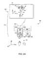
- FIG. 2Adepicts a system according to the present invention in which three-dimensional input is implemented using spaced-apart generic two-dimensional cameras, and in which a display separate from a device capturing the player input may be used, according to embodiments of the present invention;
- FIG. 2Bdepicts a system according to the present invention in which three-dimensional input is implemented using spaced-apart generic two-dimensional cameras and associated software, and in which a portable game-playing device houses the present invention, cameras and software that acquire three-dimensional game player data, as well as the game-playing system and display, according to embodiments of the present invention;
- FIG. 2Cdepicts a system according to the present invention in which three-dimensional input is implemented using time-of-flight (TOF) technology and in which a portable game-playing device houses the present invention, the single TOF camera and software that acquire three-dimensional game player data, as well as the game-playing system and display, according to embodiments of the present invention;
- TOFtime-of-flight
- FIG. 3Adepicts a game application rendered display of virtual three-dimensional game space, according to embodiments of the present invention
- FIG. 3Bdepicts the display of FIG. 3A , but as seen from a player who is now crouching down vis-à-vis player position in FIG. 3A , according to embodiments of the present invention
- FIG. 3Cdepicts the effect of introducing translation changes into the mapping software, to alter the apparent position of the game player vis-à-vis the virtual game space, using three-dimensional input, according to embodiments of the present invention
- FIG. 3Ddepicts integration of the virtual game space world with the real world, using three-dimensional input, and a three-dimensional display, according to embodiments of the present invention
- FIG. 4Adepicts uncorrected pincushion distortion, according to the prior art
- FIG. 4Bdepicts perceived positional error likely to result from uncorrected optical distortion, according to embodiments of the present invention.
- FIG. 5Adepicts line-of-sight aiming in which the display includes a representation of the player, according to embodiments of the present invention
- FIG. 5Bdepicts an image of the display for the configuration of FIG. 5A , according to embodiments of the present invention
- FIG. 6Adepicts aiming in which the display is rendered from the viewpoint of the player's head, and does not include a representation of the player, according to embodiments of the present invention
- FIG. 6Bdepicts an image of the display from the player's point of view for the configuration of FIG. 6A , according to embodiments of the present invention
- FIG. 7is a block diagram showing a preferred method to carry out the present invention, according to embodiments of the present invention.
- Table 1provides a classification overview in which rows show competing display technologies, and columns summarize competing input techniques.
- Relevant to embodiments of the present inventionare entries in Table 1 where some form of three-dimensional input is available, namely table entries denoted [B3], [B4], [C3], [C4], [D3] and [D4]).
- table entriesdenoted [B3], [B4], [C3], [C4], [D3] and [D4]
- “2D” and “3D”are used as shorthand to denote “two-dimensional” and “three-dimensional”, respectively.
- collisionin Table 1 refers to the hypothetical meeting of an input object with a game object in real space or in virtual game space, just as a tennis racket (input object) hits a tennis ball (a game object).
- the gamecreates (x, y) coordinates of screen. (x, y, z) location in the game, (x e , y e ) or (x e , y e , z e ) location with virtual 3D scenes and For simulating an event like within constraints, e.g., 3D input respect to the screen as a hint perspective projection of collision, the game must define field of view. Simulating events for a virtual camera position to the scene is displayed on a virtual z plane in the game like collisions and use two couple the perspective 3D the screen. that maps to the screen.
- the gametransforms display to the eye position. an object crosses this virtual the real (x w , y w , z w ) input plane, it can be interacted with coordinates to virtual(x, y, z) using touch or mouse events. game coordinates of the game; (b) the game transforms virtual game coordinates to real-world (x w , y w , z w ) input coordinates. The collision is resolved in either integrated coordinates.
- [D1]True 3D display (3D [D2] Input is only possible in [D3] Input is enabled in any XYZ [D4] Same usage as [C4]. output).
- the gamecreates XY coordinates of screen.
- Table 1An understanding of the noted entries in Table 1, above, is relevant to understanding the challenges associated with integrating (or unifying or mapping) the virtual game space coordinate system of a two-dimensional game application with the real-world (x, y, z) three-dimensional coordinates used by a game player to interface with the game. See for example Table 1 entries [A3], [A4], [C3], [C4], [D3], [D4].
- Table 1uses the notation (x w , y w , z w ) to refer to real world three dimensional coordinates, and the notation (x v , y v , z v ) to refer to game application or virtual world coordinates. These coordinate values define the geometric or spatial attributes of a real or virtual entity. Of course events in real world or virtual world also have a time dimension. For example the game player's fingertip may beat location (5 cm, 10 cm, 20 cm) at time 2200 seconds starting from an arbitrary zero base time.
- the notation (x w , y w , z w , t w )thus refers to both geometric (spatial) and timing data of real world objects.
- a virtual world coordinateis thus defined by the notation (x v , y v , z v , t v ) where t v defines the time dependent values of virtual world objects or events.
- tdefines the time dependent values of virtual world objects or events.
- the notion used hereis generally of the simplified form (x, y, z).
- the device executing the game applicationseeks to match the location of slingshot 20 with respect to target 60 , 70 .
- Game softwaredisplays projectile 40 moving towards the target along a mathematically determined rendered trajectory, i.e., 50 ′. If accurately aimed, the projectile smashes into the target, and the resultant mayhem is computed and rendered on display 10 by the game application software, using virtual game software coordinates. Game rules determine points earned for the player, etc.
- Some prior art approacheshave a notion of projecting internal game space onto the display screen. But, absent true three-dimensional input from the player, such games cannot render a display and game experience that mimics realistic three-dimensional player interaction with the game. For example, in prior art FIG.
- the usercannot interact with an object 60 ′ that in the game space is “in front of target 60 , nor can the user interact with an object 60 ” that in the game space is “behind” target 60 . Absent true three-dimensional player input, the user typically is limited to interacting with target 60 (which includes pigs 60 ) but is precluded from interacting with targets on a different z-plane in the virtual game space world.
- FIG. 2Adepicts a system 200 that includes an embodiment 260 of the present invention.
- a device or game playing device 220includes system 245 , which will include memory 241 , within which is stored game application 242 and, if modified, 242 ′, and processor 244 , which executes software including game application 242 , 242 ′.
- Game device system 245may further include firmware and hardware.
- therepreferably is sharing of processing and/or memory functions between game system 245 and system 260 .
- System 260is shown as including at least a processor 262 , and memory 264 including at least one executable routine 266 to carry-out the present invention.
- processor functionality and memory functionality between game device system 245 and system 260are preferably shared.
- processor 262may in fact be processor 244 in system 245 , and in practice, memory 264 may be part of memory 241 in system 245 .
- Further software 266 in system 260may be stored in memory associated with system 245 in gaming device 220 .
- System 200includes a game-playing capable device 210 , shown here as including a device 220 coupled (via circuit traces, wire, or wirelessly) to monitor 225 that renders display 10 .
- monitor 225may alternatively be considered as showing, in larger size, what appears on a display 10 , if present, on device 220 .
- Many devices 220include gyros, accelerometers, and the like, shown generically as 255 .
- System 200also includes system 260 , implementing the present invention.
- Data from accelerometer 255can be used to determine orientation of device 220 , that is, how player 100 may be holding the device (which device could of course be stationary on a table top).
- systems 230 and/or 260can swap x w and y w data, and applications(s) 242 can re-orient the content rendered on display 10 , landscape to portrait mode, perhaps.
- player 100can interact with device 220 when the device is stationary, perhaps sitting on a desk.
- module or system 230represents a preferred method to implement three-dimensional gathering functionality for system 200 , whereby movements, gestures, etc. of player 100 (shown as a clenched and as an open player right hand) can be tracked substantially in real-time in real-world coordinates (x w , y w , z w ). (Other methods or systems to gather such real-world coordinates (x w , y w , z w ) in real-time may of course be used). Note that display 10 in FIG. 2A combines the aiming mechanism, e.g., slingshot 20 , and the target 60 in a single display.
- aiming mechanisme.g., slingshot 20
- system 230includes spaced-apart two-dimensional cameras 240 A, 240 B that are coupled to software 250 , which processes the optical image data gathered by the cameras.
- a preferred method and system to implement detection system 230is set forth in pending U.S. patent application Ser. No. 13/385,134, filed 3 Feb. 2012, entitled “Two-Dimensional Method and System Enabling Three-Dimensional User Interaction With a Device”, assigned to Imimtek, Inc. of Sunnyvale, Calif., assignee herein.
- cameras 240 A, 240 Bsubstantially simultaneously capture from their respective vantage points two-dimensional images of at least a portion of game player 100 as gestures and the like are made, perhaps with the free right hand, with body movements, etc.
- the camera sensorsdetect RGB, monochrome, or even IR spectral energy, but need not be identical in terms of resolution and fields of view, or even spectral sensitivity.
- the overlapping fields of view of the two camerasdefine a three-dimensional hover zone that can include the surface of display 10 , a three-dimensional space within which player gestures may be captured optically and interpreted.
- the camerasare pre-calibrated and are mounted at opposite corners of device 220 to better capture player gestures.
- Aggregated frames of two-dimensional information acquired by the camerasare communicated at a frame rate for processing by an electronic system, associated with module 250 in FIG. 2B . Signal processing upon this two-dimensional information can identify potential landmark points on the player as needed representing imaged object(s), perhaps the centroid of player's right hand, the tip of a finger, etc.
- the imaged playeris skeletonized for representation by a relatively small number of landmark points, typically fewer than about one hundred potential landmarks, and perhaps only a dozen or so landmarks.
- Signal processing within module 250then yields three-dimensional (x w , y w , z w ) data for the relatively few landmark points defined on the imagery acquired by cameras 240 A, 240 B.
- module 250can operate rapidly, substantially in real-time, using inexpensive components to yield three-dimensional reconstruction of relevant landmark points.
- Gesture recognitionis carried out by module 250 , from which the gesture recognition data goes to system 260 .
- the gesture recognition datamay be fed back to the game application 242 , 242 ′, which as noted is typically disposed within game device system 245 , to alter game play imagery rendered on display 10 in response to detected player interaction.
- the above-described Imimtek, Inc. methodmay be implemented exceedingly inexpensively using generic components having a resultant tiny form factor.
- the described methodcan be implemented in mass production for less than about $10, e.g., using generic two-dimensional cameras such as OmniVision model OV7740 VGA, see www.ovt.com, which cameras in quantity cost less than about $1. While horizontal and vertical camera FOVs of 90° would be ideal, the narrower 40°-50° FOVs of OmniVision model OW740 VGA cameras work acceptably in practice.
- spaced-apart two-dimensional cameras 240 -A, 240 Bare disposed at opposite corners of device 220 such that their overlapping optical fields of view (FOV) define a three-dimensional zone in which the cameras can image at least portions of the game player 100 .
- the camerascan be mounted such that the overlapping FOV grazes the surface of display 10 , to also detect (if desired) physical contact by player 100 with the surface of display 10 .
- device 220might be a handheld smart phone equipped with system 230 , and coupled to display video on monitor 225 .
- FIG. 2Aunlike what was described with respect to FIGS.
- player 100can aim projectile 40 at target 60 ′ disposed in front of primary target 60 , and can also aim projectile 40 at target 60 ′′ disposed behind target 60 , as there is indeed a sense of depth z v in the virtual game space (x v , y v , z v ) that is now present.
- embodiments of the present inventionpresent player-interactable depth regions on display 10 , e.g., targets 60 ′, 60 ′′, in addition to target 60 .
- FIG. 2Adepicted a game playing device 220 functionally coupled to a separate monitor display 225 , 10 .
- system 200includes a device 220 that includes monitor 225 (and display 10 ) as well as systems 230 and 242 , 245 as an integral part of the device, all in a common housing.
- the game playing devicemay be referred to as 210 or as 220 .
- functionality of much if not all of system 260preferably can also be disposed in the same housing as device 220 and display 10 , etc.
- system 230 generated (x w , y w , z w ) datais coupled to the present invention, system 260 , which maps this real-world data to game-world virtual coordinates (x v , y v , z v ) coordinates and performs any real-world to virtual-world scaling as may be desired, e.g., to make player gesture movements realistic to the scale of the rendered game image.
- System 230then interfaces with game application 242 , 242 ′ and game system 250 to cause the game to respond to the detected player gesture or other movements, which interaction preferably is perceived from the eye or viewpoint of the player.
- real-time generated (x w , y w , z w ) dataenables system 260 to cause the game application to respond to natural gestures made by player 100 .
- One aspect of the virtual world data that is createdis the player or an icon or avatar of the player can be rendered on display 10 to become part of the on-going game play.
- FIG. 2Bdepicts an embodiment of the present invention in which system 200 is implemented as a single portable device 210 that includes system 230 (cameras 240 A, 240 B, module 250 ), as well as module 242 , 242 ′, 245 , and if present gyro, accelerometer components 255 . Preferably all of these components or systems or modules are disposed in the housing or case for device 220 .
- screen display 10is shown with rendered images of an aiming device 20 (a slingshot), a target 60 (replete with pigs), a projectile 40 that has traveled along a player determined trajectory 50 ′.
- Many devices 210include gyros, accelerometers, and the like, shown generically as 230 .
- Devices 210that include such mechanisms 230 enable a player 100 to physically tilt and/or rotate the device to influence game play.
- player 100is holding device 210 in her left hand, which may be used to tilt, rotate the device, and has also created a gesture with her right hand in firing slingshot 20 .
- data from an accelerometer or gyroscopecan be used to determine orientation of device 220 , that is the manner in which the user is holding the device.
- orientation data sensed by device 210can enable systems 230 and/or 260 to swap x w and y w data, whereupon software applications(s) 242 can re-orient content rendered on display 10 . Note that the embodiment of FIG.
- Display 10optionally includes a three-dimensional display 10 .
- Display 10may be auto-stereoscopic or may require user 100 to wear stereoscopic glasses.
- virtual slingshot 20appears to player 100 to hover in three-dimensional real-world space. (see all FIG. 3D , in which virtual target object 130 ′ also appears to hover in three-dimensional real-world space.)
- a display 10 capable of outputting three-dimensional imagerymay be provided for other embodiments of the present invention.
- display 10may simply output conventional two-dimensional imagery, for use with embodiments of the present invention.
- three-dimensional input datais again preferably obtained using system 230 comprising preferably pre-calibrated cameras 240 A, 240 B, and module 250 , as described above with respect to FIG. 2A .
- system 230is built into the housing of device 220 .
- cameras 240 A, 240 Be.g., OmniVision model OV7740 VGA units, are disposed at opposite corners of display 10 , to provide a good overlapping of their respective FOVs, the better to capture gestures and other movements by player 100 .
- Functionality of module 250preferably is as described above with respect to FIG. 2A . While an Imimtek, Inc. method of acquiring three-dimensional data representing player gestures is inexpensive and readily mass-producible, the present invention may be implemented independently of how the (x w , y w , z w ) data is generated.
- player 100can better visually control the slingshot trajectory using natural gestures, perhaps opening and closing the right hand, moving the right hand, etc. in real-world (x w , y w , z w ) three-dimensional space.
- the centroid position of the user's hand relative to say display 10will be discernible to the game system 245 , 242 , 242 ′.
- the playermight close the fingers of the right hand (to grasp projectile 40 ) and move the right hand left or right, up or down (in the x-y plane) to aim the projectile. Moving the hand away from or toward display 10 (along the z-axis, in the real world) could impart greater or less tension to the slingshot.
- system 260implementing embodiments of the present invention preferably is as described with respect to FIG. 2A .
- processor, storage, and executable software functionality in system 260may be shared with such functionality found in system 245 of the gaming device, e.g., processor 244 , memory 241 .
- FIG. 2Cdepicts an embodiment of the present invention that gathers three-dimensional input data representing player movement using a time-of-flight (TOF) camera 270 and associated electronic system module 280 .
- TOF cameraemits active optical energy of known phase, some of which is reflected back toward the camera by portions of player 100 .
- Module 280can determine vector distance (x w , y w , z w ) to regions of player 100 by comparing phase shift between active emitted optical energy and player reflected-back optical energy.
- Descriptions of exemplary TOF systemsmay be found in the many U.S. patents obtained by Canesta, Inc. of Sunnyvale, Calif., which patents are now assigned to Microsoft, Inc. of Redmond, Wash.
- display 10is (optionally) a three-dimensional output device able to display three-dimensional images, with the result that virtual slingshot 20 appears to player 100 to float in real-world space.
- FIG. 3A-FIG . 3 Dwithout loss of generality, representations of virtual world game space and various real-world three-dimensional space are depicted generically for exemplary games including two-dimensional games such as Angry Birds.
- shaded plane 10is the front display plane, and the plane where target 130 appears to be in FIG. 3A is further back, e.g., in the back of game space 120 .
- FIG. 3Adepicts display 10 , whereon the game application renders the illusion of a three-dimensional virtual world (i.e., game space) 120 that includes target 130 (perhaps shelter 60 , pigs 70 ) and an aiming crosshair sight 140 (perhaps slingshot 20 ).
- the virtual three-dimensional game spacehas its own three-dimensional coordinate system (x v , y v , z v ). Without loss of generality, the (0 v ,0 v ,0 v ) origin of this virtual three-dimensional coordinate system is shown anchored to the lower left corner of display screen 10 , although it could of course be anchored elsewhere.
- FIG. 1depicts display 10 , whereon the game application renders the illusion of a three-dimensional virtual world (i.e., game space) 120 that includes target 130 (perhaps shelter 60 , pigs 70 ) and an aiming crosshair sight 140 (perhaps slingshot 20 ).
- the virtual three-dimensional game spacehas its own three-dimensional coordinate system (x v
- a three-dimensional real-world input coordinate system(x w , y w , z w ) is defined with respect to an origin (0 w ,0 w ,0 w ) anchored to the upper left corner of display screen 10 , although it too could be defined with respect to another location.
- the offset between the centers of the two coordinate systemsis essentially the height (Y disp ) of the display screen, a readily discernible dimension.
- the offset parameterwould be zero.
- the rotational (angular) offsettypically referred to as ( ⁇ x , ⁇ y , ⁇ z ) between these two coordinates systems is defined in radians or angles and is assumed to be zero in FIG. 3A , although non-zero values can also be defined.
- three-dimensional real-world (x w , y w , z w ) coordinate datais produced for use by the game application.
- game player 100whose eye and view point is denoted 150 , and whose right pointing fingertip is denoted 160 ) occupies the real world, and looks at display surface 10 .
- a relationship between real world three-dimensional coordinates and virtual game space coordinatesis needed if the game player is to successfully observe and interact with the two-dimensional virtual world as rendered on display 10 .
- Real world coordinatesare denoted as (x w , y w , z w ), and software provided by the present invention can produce real world data, such as the coordinates (x w h , y w h , z w h ) for fingertip 160 , as well as other relevant coordinates for portions of the body of player 10 , in a natural interface embodiment.
- display 10demarks the boundary between the real world, e.g., the world external to the viewing surface of the display, and the virtual game world, e.g., that which is rendered as viewable imagery on display 10 .
- R and Tmay be conventional rotation and translation matrices from real-world coordinates to virtual world coordinates.
- a scaling factormay be introduced into the above transformation to account for differences in measurement units.
- the game applicationmay require a 10 cm movement by the player in the real world to represent a 10 m distance in the virtual game world.
- each of the three dimensions (x, y, z)may have its own, different, scaling factor value.
- the same scalingmay be applied to other terms, such as time, velocity, inertia, etc., associated with game movements, user gestures, etc. coupled to the game system.
- player created real-world three-dimensional input datacan be represented in the same three-dimensional virtual world, along with objects that are rendered (or materialized) in the three-dimensional game space.
- Rthe definition of R will depend upon the values and effects that the game application engine wants to achieve, although in the simplest form, R could be a unity matrix.
- the game application enginecan also alter values for T.
- a transformed virtual representation of at least a part of player 100is rendered as virtual player portion 100 ′ as though immersed in game-world space.
- Thiscorresponds to Table 1, entries [C3] or [C4]. It is obviously useful to the player to “see” where the game application thinks his hand 100 is in game-world space.
- the virtual game-world location of player portion 100 ′preferably is rendered to appear projected as 100 ′′ at a computed location on two-dimensional display screen 10 in FIG. 3C to provide feedback to the player as to movement of hand 100 .
- This game world space locationwill be commensurate with the perceived position of player portion 100 in the real world with respect to the virtual target 130 .
- the three-dimensional output data generated by software associated with embodiments of the present inventionmay be used to extend the virtual game world into the real world, as shown in the embodiment of FIG. 3D .
- Thiscorresponds to Table 1, entries [D3] or [D4].
- a three-dimensional displayis rendered, e.g., perhaps using a holographic display, or a three-dimensional display for which the game player will wear stereoscopic glasses, or perhaps using an auto-stereoscopic display.
- virtual target 130is created by the game application in the virtual world and appears to be moved into the real world as target 130 ′, which may appear to the player to float in real-world three-dimensional space with player hand object 100 .
- scaling of motion properties (velocity, acceleration, direction) in the virtual worldshould match the corresponding metrics in the real world.
- thisis achieved because the three-dimensional input produces (x w , y w , z w ) data substantially in real-time. What remains is to set the game application time clock to match the real world clock, as perceived by player 100 to further promote realism of the game play.
- the present inventioncan, if desired, cause scenes to be rendered on display 10 , from player 100 's line of sight 150 .
- the user's eye(s)are within the field of the three-dimensional real world optical acquisition system, e.g., within the field view of spaced-apart cameras 240 A, 240 B (embodiment of FIG. 2B ), within the field of view of TOF camera 270 in the embodiment of FIG. 2C , etc.
- the player's eyecan be located in three-dimensional real world space.
- the three-dimensional location of the player's eye 150can then be used as the location position of a virtual camera position.
- the location of a virtual camera positionrefers to a computer graphics meaning of the term and not to the physical location of the optical camera(s), e.g., 240 A, 240 B, or TOF camera 270 used to acquire real-world imagery.
- the optical camera(s)e.g., 240 A, 240 B, or TOF camera 270 used to acquire real-world imagery.
- embodiments of the present inventioncan use calibration information to remove distortion from the image acquired by the optical camera(s) and thus determine the correct optical ray associated with the physical location of the player's eye 150 . Even if the player's face is not completely visible to the acquiring camera(s), the image will nonetheless include clues, e.g.
- optical calibration associated with the lens in data-gathering cameras 240 A, 240 B, or in the time-of-flight embodiment, associated with TOF camera 270wants to be accounted for to minimize inaccuracies.
- uncorrected camera lens distortioncan produce erroneous location coordinates for the game player's head with respect to the camera(s), especially if the head moves to a location beyond the overlapping field of view of two-dimensional cameras 240 A, 240 B.
- FIG. 2Bunless two-dimensional cameras 240 A, 240 B were calibrated to remove lens distortion, the location of the player's head could only approximately be discerned in three-dimensional space.
- embodiments of the present inventionrelate to methods of using three-dimensional input data to enable two-dimensional game applications to render more realistic displays to enhance realism.
- successful interaction between game applications and the presentrealistically require the use of calibration information to un-distort images acquired by 240 A, 240 B.
- uncorrected image 280 in FIG. 4Aof a perfectly regular rectilinear pattern of lines
- pincushion errorwill be present.
- FIG. 4Bunless such pincushion error is corrected for, it can produce erroneous estimations of the direction of the game player's eye 150 .
- FIG. 4Bdepicts the problems created by uncorrected optical distortion.
- FIG. 4Bdepicts an image plane 290 of a two-dimensional camera, e.g., 240 A, or 240 B, and shows pixel sensors 300 thereon, typically formed as an array of rows and columns.
- camera 240 A or 240 Bcaptures an image, that image ideally is focused by camera lens 310 , which has optical axis 320 , upon image plane 290 .
- Incoming optical energyis detected by the array of pixel sensors 300 on image plane 290 .
- pixel sensors 300may be sensitive to visible light including monochrome and/or color RGB spectra, or to IR. As shown in FIG.
- an imaginary or virtual image plane 330may be said to exist in the real world, with camera lens 310 midway between virtual image plane 330 and image plane 290 .
- the actual position of the game player's eye 150 as the eye sights along a light ray 340will be at A (x e , y e , z e ).
- uncorrected optical distortionhas the effect of appearing to shift the position of the game player's eye to spurious position A′ (x′ e , y′ e , z′ e ), as though ray 340 ′ were being sighted upon, rather than ray 340 .
- reconstructing a three-dimensional image projection from the perspective of the player's eye by the game applicationmay not reflect the true position of the player's eye.
- Of course 150could refer to another portion of the player, e.g., an arm, hand, torso, etc., and game gestures made by the player could be misinterpreted or go unrecognized.
- game gestures made by the playercould be misinterpreted or go unrecognized.
- uncorrected errorscan diminish quality of game play, e.g., correctly aimed projectiles may miss their target, player gestures including natural gestures may be misinterpreted, etc.
- FIGS. 3A and 3Bit is natural to aim at a target 130 by having the game player align the player's eye, hand, etc., perhaps using a sight aiming object such as 140 , e.g., a cross-hair.
- a sight aiming objectsuch as 140
- the player's eye 150 and hand 100are materialized in the real world and are located with real-world coordinates, whereas the aiming-assist 140 and target 130 are rendered in the virtual world using respective virtual world coordinates.
- embodiments of the present inventioncan integrate real world coordinates and virtual world coordinates. According to embodiments of the present invention, this functionality enables the game application to be provided with sufficient information to render an aiming scene with realism and with high visual fidelity on display 10 .
- realismmay include a realistic depiction of the trajectory 50 ′ of projectile 40 (a bird, a missile, an arrow, a stone, etc.).
- the aiming metaphor used hereinis not limited to literally aiming a projectile at a target.
- the term “aiming”may mean “selecting”, or “identifying” among several user interface targets, perhaps displayed objects such as button(s), slider(s), hot link(s), object edge(s), and so forth.
- FIG. 5Adepicts successful implementation of line-of-sight aiming by which player 150 can look along site line 350 toward virtual target 130 in virtual game space.
- the game sceneis rendered on display screen 10 from the perspective of the game.
- slingshot 20or alternatively perhaps an aiming cross-hair 20 (or 140 ) is effectively coupled with the player's eye 150 , and is effectively decoupled from the rest of the scene (e.g., trees, structures, birds, etc.).
- the game scene displayedwill be governed by the game application, and any appropriate scene can be rendered as required by the flow of the game, responsive to player 100 interactions such as gestures.
- FIG. 5Ashows the three-dimensional detection zone 360 defined by the intersecting fields of view of two-dimensional cameras 240 A, 240 B. (It is understood that camera 240 B is spaced-apart from camera 240 A by approximately the horizontal width of display screen 10 , and would appear at that distance normal to the plane of the drawn image.) Player 150 sights along line 350 using slingshot 20 (or, alternatively perhaps a cross-hair 140 ) as an aiming guide.
- aiming and launching projectile 20 such that it will hit target 130requires user 100 to align hand and finger 160 in the line-of-sight along cross-hair 20 (here shown as a slingshot) and target 130 (see FIG. 5B ).
- the trajectoryis now depicted in FIG. 5A as a line 350 , and is shown as a curved trajectory 50 ′ in FIG. 5B .
- player 100has aimed and launched projectile 20 accurately and a hit upon target 130 will result.
- the position of the player's hand 100 and eye 150are present in the real world and will have real world three-dimensional coordinates, as shown.
- Target 130 and aiming guide 20are rendered in the virtual game world and will have respective virtual game world coordinates.
- the real world coordinates and the virtual game world coordinatespreferably are integrated, according to embodiments of the present invention.
- the two-dimensional game applicationnow has sufficient integrated three-dimensional virtual world coordinate information relating to position, velocity, acceleration, etc. to render upon display 10 the aiming scene with high visual fidelity. Consequently a very realistic game experience is provided for the player.
- FIG. 6Ais similar to FIG. 5A , but depicts at least one advantage of rendering game scenes from the player's eye point of view.
- the game sceneis rendered on display screen 10 from the perspective of the user's eye.
- slingshot 20(or alternatively perhaps a cross-hair 140 ) is effectively coupled with the player's hand and decoupled from the rest of the scene (e.g., trees, structures, birds, etc.)
- the rest of the scenee.g., trees, structures, birds, etc.
- the rest of the imagery rendered upon display 10remains substantially unchanged.
- FIG. 6A and FIG. 6BAn advantage of embodiments of the present invention with respect to target visibility and aiming is shown in FIG. 6A and FIG. 6B .
- player 100aims projectile 40 by aligning hand and finger 160 in a trajectory towards a desired target.
- the embodiment of FIG. 6Balso enables player 100 to interact with target 60 ′, disposed in front of target 130 , e.g., along the z w axis closer to display 10 , as well as to interact with targets such as 60′′ disposed behind target 130 , e.g., further away from display surface 10 , along with z w axis.
- alternate trajectory 50 ′′depicts how player 100 has moved his or her hand and imparted sufficient virtual force to intentionally lob a projectile over target 130 to intentionally hit target 60 ′′ disposed behind target 130 . Further, the player enjoys greater visibility of these alternate targets 60 ′, 60 ′′.
- target 130could be an obstacle, perhaps a mountain, disposed in front of a desired target 60 ′′.
- game pointscould be deducted from the player's score.
- the enhanced visibility and depth ordering (e.g., along axis z y ) of targets 60 ′, 130 , 60 ′′ in the embodiments of FIG. 6A and FIG. 6Bcontribute to a more realistic three-dimensional game experience for the player.
- a clenched player handmay be defined as one natural gesture, perhaps “sight target”, and an open player hand may be defined as a second natural gesture, perhaps “fire”.
- gesturescan in addition or alternatively include, without limitation, movement of the hand(s), arm(s), torso, head, etc.
- strength of the player's pull upon slingshot 20can be ascertained in terms of movement along the z-axis, away from (perhaps greater pull strength) or towards (perhaps less pull strength) display 10 .
- Vector aiming of slingshot 20can be determined from the three-dimensional data gathered from player 100 , e.g., by cameras 240 A, 240 B (see FIG. 2B ), or by a time-of-flight camera (see FIG. 2B ), or by any other three-dimensional acquisition system.
- the game device 220may include hardware 230 that includes gyros, accelerometers (collectively 255 ), and the like. Further the physical screen of display 10 may be sensitive to the player's touch, or spaced-apart cameras 240 A, 240 B can be adjusted to sense touching of display 10 . Such additional information from these sense mechanisms may be input by the present invention to the game application to communicate additional player movement information.
- the playermay simply place device 210 on a stationary object, perhaps a table top, in which case the player could use both hands to interact in three-dimensional real-world space with the game-playing device, or perhaps compete against another player, who is also interacting with the game-playing device.
- system 260(in FIGS. 2A-2C ) preferably implements embodiments of the present invention, and typically will include at least a processor 262 , and memory 264 storing at least one processor 262 executable routine 266 implementing the present invention.
- system, 260 processor, memory, and routine execution functionsmay be shared or carried out by processor and memory capability within game device system 245 .
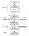
- FIG. 7depicts a flow chart 500 showing preferred method steps executed by system 260 to carry out embodiments of the present invention.
- FIG. 7depicts a flow chart 500 showing preferred method steps executed by system 260 to carry out embodiments of the present invention.
- initialization procedures(steps 510 - 540 ) that are directed to conventions and calculations relating to mapping between the real-world or physical-world and the virtual application world are carried out, and post-initialization run-time processing (steps 550 - 640 ) that are directed to exemplary run-time logic that repeats during operation of system 260 .
- post-initialization run-time processing(steps 550 - 640 ) that are directed to exemplary run-time logic that repeats during operation of system 260 .
- post-initialization run-time processing(steps 550 - 640 ) that are directed to exemplary run-time logic that repeats during operation of system 260 .
- initial mapping procedures(steps 510 - 540 ) that are directed to conventions and calculations relating to mapping between the real-world or physical-world and the virtual application world are carried out
- post-initialization run-time processing(steps 550 - 640 ) that are directed to exemplary run-time logic that
- step 510defines center, orientation and measurement units of the coordinate system, and other parameters of the physical real world associated with the game player (or user).
- the coordinate centercan be assumed to be at the lower left corner of display 10 , with orientation such that y represents the up/down direction, x the left/right direction, and z represents a direction toward the user.
- unit measurementsare defined in mm although other orientations and units could instead be used.
- motion parametersare defined accordingly to correspond to real-world values, e.g., velocity may be on the order of cm/second, time measured per a wall clock, etc.
- Step 520 in FIG. 7specifies similar parameters in the game or application context. For example if game application 242 involves flying rockets, velocity measurements may be defined in kilometers per second. If game application 242 has already defined a three-dimensional virtual world, a system of three-dimensional coordinates will likely have already been defined. However if not, step 520 will add such a coordinate system and define its center. In practice a game or game application (e.g., 242 , 242 ′) may have many dynamic scenes and thus the virtual coordinate system parameters may be updated in each scene. Such updates preferably are carried out in FIG. 7 by method step 640 .
- a game or game applicatione.g., 242 , 242 ′
- Such updatespreferably are carried out in FIG. 7 by method step 640 .
- step 530 in FIG. 7determines the geometric rotation (R) and translation (T) transformation parameters between these two coordinate systems. These geometric transformation parameters, which may be from real-to-virtual or from virtual-to-real, are needed for coordinate transformations (see steps 570 or 580 ).
- Block 540 in FIG. 7specifies mapping between scaling and timing (motion) parameters between real and virtual worlds.
- velocity in the virtual worldmay be at Mach-level magnitude
- velocity in the game player's real worldmay be in the magnitude of cm/sec.
- time scalinga ten second clock time in real world may map to days or perhaps nanoseconds in the game virtual world.
- the scaling mapping between each coordinatemay of course differ.
- (x,y) scale mappingmay be one-to-one
- z scale mappingmay be one-to-ten.
- game application 242may update scale and timing mappings at run-time, depending on scene changes, which updates are applied at method step 640 .
- initializationtypically has been completed and run-time loop application commences with method step 550 .
- loopdoes not mean that game application 242 is required to always follow a pre-determined loop. Instead, the game application logic may dictate that the application state follow a complex network of states. But for clarity of illustration and brevity, the game application run-time logic may be defined as a loop.
- spaced-apart two-dimensional cameras 240 A or 240 Bcapture substantially simultaneous frames of the game player.
- module 250 and associated software(executable internally or running on the processor and memory of 260 ) performs three-dimensional re-construction of centroid and other relatively few landmark points such as the player's fingertips, eye(s), face, etc., assuming these player body parts are within the overlapping fields of view of cameras 240 A, 240 B.
- centroid and other locationsare determined in three-dimensional real-world (x w , y w , z w ) coordinates.
- Module 250may also perform additional gesture processing to translate such three-dimensional real-world player data into a gesture language or commands for use by device 220 .
- method step 550represents such capture of real-world player data.
- the resultant gesture(s) or other command(s)are used to drive game application 242 , 242 ′ so as to interact, preferably highly realistically, with the game player.
- Method step 560 in FIG. 7determines whether system 210 or display 10 ( FIG. 2A ) supports some form of three-dimensional output, perhaps an auto-stereoscopic display. Step 560 further decides if three-dimensional output is optionally available, whether game application 242 , 242 ′ wants to make use of it to render a three-dimensional display on monitor screen 10 . If the answer is affirmative, the method flow at step 560 branches right (‘YES’) to step 570 . Of course, if system 210 does not support a form of three-dimensional output, or if the system wants to use a usual two-dimensional display, where both two-dimension and three-dimension options are available, at step 560 the method flow branches left (‘NO’) to step 580 .
- step 570preferably module 260 (see FIG. 2A ) using processor 262 , memory 264 , routine 266 (and/or using equivalent functionalities within system 245 ), the locations of virtual objects in game space coordinates (x v , y v , z v ) are translated to world coordinates (x w , y w , z w ), commensurate with the three-dimensional output coordinate system.
- These translationspreferably use transformation parameters obtained at step 530 , or as updated at step 640 . Note that even if a three-dimensional object appears to materialize in the real world (e.g., FIG. 3D ), the real world location whereat it appears is somewhat related to the perception of the game player. Understandably it is desirable to properly determine the scale of this transformation.
- a game object like a ballshould be rendered so as to appear on display screen 10 to be reachable by and inter-actable with the game player's hand.
- embodiments of the present invention within module 260can use processor 262 , memory 264 and routine 266 to carry out a reverse translation from world coordinates (x w , y w , z w ) to virtual game space coordinate (x v , y v , z v ).
- processor functions, storage functions, etc.preferably are shared between system 260 and system 245 , in which case processor 244 in system 245 may be used to carry-out such functions.
- routine 266can be stored in memory 241 in system 245 .
- Such reverse translationpreferably will use transformation parameters obtained at step 530 , or updated at step 640 .
- the real world objectstypically are obtained from player gestures and other data, and represent player hand, perhaps finger tips, facial coordinates, etc; see method step 550 in FIG. 7 .
- a representation of the playershould appear to reach a game object such as a ball in virtual game space.
- a unification of geometric and timing scalingis preferably carried out at step 590 within system 260 to produce a unified real/virtual coordinates system (x u , y u , z u , t u ).
- a projectile that travels at Mach magnitude speed along a trajectorymay be slowed to slower speeds commensurate with the real world speed of player hand movements.
- method step 600governs the perspective by which the game application display content is rendered, either on a two-dimensional screen display, or on a real world three-dimensional rendering. For example, if method step 550 provides player eye location, game application 242 or 242 ′, running within game system 245 , draws a two-dimensional or three-dimensional rendering of the game application scene from the perspective of the game player's eye; see method step 610 . If the player eye location is not available or not needed, game application 242 or modified 242 ′, again running within game system 245 , draws a two-dimensional or three-dimensional rendering of the game application scene. This rendering will be according to the internal rules of the game application, or from the perspective of the perceived location of user eye; see method step 620 .
- Method step 630 in FIG. 7is directed to the interaction between the game application 242 or 242 ′ logic, and processed player input from method step 550 , following the aforementioned translations, scaling and unification steps that drive the game application.
- the targetingusing slingshot 20 or crosshair 140 (see FIG. 2A and FIG. 3A-3D ) and the launching of projectile 40 (see FIG. 2B or FIG. 2C ) are performed at method step 630 , per game application software modules 242 or 242 ′.
- the game application clock(or in a more general term, the game application logic) is advanced to the next state. If the current state of the game application requires updating any coordinate transformation, timing or scaling parameters between the virtual world coordinates and real world coordinates (as described for steps 530 and 540 ), such parameters are updated at method step 640 .
- the previous steps in the loopnamely steps 570 , 580 , 590 , will use the updated information for their computation that takes place in system module 260 , for use by game system module 245 .
- a game application 242may support internal virtual three-dimensional coordinates, but the method to drive that application is a traditional two-dimensional input, e.g., a touch display screen, a keyboard, etc.
- the game applicationmay already map two-dimensional inputs (e.g., CTRL (Control) key+up/down arrow keys) to the z-dimension for complete virtual three-dimensional actions.
- operation of these arrow keysmay change z v values in game application (x v , y v , z v ) coordinates while maintaining the values of x v and y v .
- Substantially simultaneously values of x v and y vmay be changed using the left/right and up/down arrow keys, without the CTRL key, and can be assigned to change values of x v and y v , correspondingly.
- the player-game interactionwill not be very natural.
- game application 242is modified to game application 242 ′ to behave like an application in category [C3] in Table 1.
- the transformations in method steps 580 and 590can be performed in module 260 (see FIG. 2A ).
- the resulting (x v , y v , z v ) valuesare then mapped to key codes for left/right, up/down, and CTRL up/down keys, just as if the game player were entering these keys to interact with the game application.
- a further step in modifying game application 242can bypass translation from three-dimensional (x w , y w , z w ) input data to two-dimensional (keyboard keys) input data, and from two-dimensional to three-dimensional (x v , y v , z v ) coordinates. Further, the method steps of system 266 may be integrated into system 242 resulting in an incarnation of modified game application 242 ′.
- embodiments of the present inventionmay be used with game and/or with other applications that can respond to three-dimensional input.
- devices executing such applicationmay include mobile or handheld platforms including smart phones, tablets, portable game consoles, laptop and netbook computers, in addition to non-mobile platforms, perhaps PCs, TVs, entertainment boxes, among other appliances.
- embodiments of the present inventioncould also be deployed to enable a user to manipulate menu(s) rendered on a display screen, to engage virtual selection button(s) rendered on a display screen, etc.
Landscapes
- Engineering & Computer Science (AREA)
- Multimedia (AREA)
- Human Computer Interaction (AREA)
- Theoretical Computer Science (AREA)
- User Interface Of Digital Computer (AREA)
Abstract
Description
| TABLE 1 | |||
| [A1} | [A2] 2D Input (e.g. mouse, | [A3] 3D input control | [A4] 3D Player eye position |
| touch, buttons) | (e.g., non-touch hover) | input (e.g. through head | |
| and/or face tracking) plus 2D | |||
| or 3D input control | |||
| [B1] 2D display: Planar 2D | [B2] Input is in the same planar | [B3] Input provides additional z | [B4] |
| views of the scenes are | (x, y) coordinate of display | coordinates. If the game is not | |
| shown. Motions are | screen. | programmed for handling z, z | |
| exclusively in x (horizontal) | data will remain unused. | ||
| and y(vertical) directions. | |||
| [C1] | [C2] Input is only possible in | [C3] Input is enabled in any | [C4] Use the real world eye |
| display. The game creates | (x, y) coordinates of screen. | (x, y, z) location in the game, | (xe, ye) or (xe, ye, ze) location with |
| virtual 3D scenes and | For simulating an event like | within constraints, e.g., 3D input | respect to the screen as a hint |
| perspective projection of | collision, the game must define | field of view. Simulating events | for a virtual camera position to |
| the scene is displayed on | a virtual z plane in the game | like collisions and use two | couple the |
| the screen. | that maps to the screen. When | options: (a) the game transforms | display to the eye position. |
| an object crosses this virtual | the real (xw, yw, zw) input | ||
| plane, it can be interacted with | coordinates to virtual(x, y, z) | ||
| using touch or mouse events. | game coordinates of the game; | ||
| (b) the game transforms virtual | |||
| game coordinates to real-world | |||
| (xw, yw, zw) input coordinates. The | |||
| collision is resolved in either | |||
| integrated coordinates. | |||
| [D1] True 3D display (3D | [D2] Input is only possible in | [D3] Input is enabled in any XYZ | [D4] Same usage as [C4]. |
| output). The game creates | XY coordinates of screen. Use | location in the game (within 3D | Except the scene shall be |
| the illusion that scenes are | of buttons or an auxiliary touch | input field of view and | rendered in 3D from the |
| materialized in real 3D | surface constraints the game | constraints). For simulating | perspective of the player eye |
| world. | control. The direct and realistic | events like collisions, the | subject to the angular |
| interaction with game objects is | preferred option is that the game | limitation of the | |
| not achievable or severely | transforms the virtual | display technology. | |
| constrained. | coordinates of the game to the | ||
| real (xw, yw, zw) coordinates of | |||
| input. The collision is resolved in | |||
| the illusion of the real world | |||
| coordinates. | |||
where R and T may be conventional rotation and translation matrices from real-world coordinates to virtual world coordinates.
Claims (8)
Priority Applications (2)
| Application Number | Priority Date | Filing Date | Title |
|---|---|---|---|
| US13/506,474US8840466B2 (en) | 2011-04-25 | 2012-04-20 | Method and system to create three-dimensional mapping in a two-dimensional game |
| US14/476,666US9504920B2 (en) | 2011-04-25 | 2014-09-03 | Method and system to create three-dimensional mapping in a two-dimensional game |
Applications Claiming Priority (2)
| Application Number | Priority Date | Filing Date | Title |
|---|---|---|---|
| US201161517657P | 2011-04-25 | 2011-04-25 | |
| US13/506,474US8840466B2 (en) | 2011-04-25 | 2012-04-20 | Method and system to create three-dimensional mapping in a two-dimensional game |
Related Child Applications (1)
| Application Number | Title | Priority Date | Filing Date |
|---|---|---|---|
| US14/476,666ContinuationUS9504920B2 (en) | 2011-04-25 | 2014-09-03 | Method and system to create three-dimensional mapping in a two-dimensional game |
Publications (2)
| Publication Number | Publication Date |
|---|---|
| US20120270653A1 US20120270653A1 (en) | 2012-10-25 |
| US8840466B2true US8840466B2 (en) | 2014-09-23 |
Family
ID=47021742
Family Applications (2)
| Application Number | Title | Priority Date | Filing Date |
|---|---|---|---|
| US13/506,474Active2032-08-07US8840466B2 (en) | 2011-04-25 | 2012-04-20 | Method and system to create three-dimensional mapping in a two-dimensional game |
| US14/476,666Expired - Fee RelatedUS9504920B2 (en) | 2011-04-25 | 2014-09-03 | Method and system to create three-dimensional mapping in a two-dimensional game |
Family Applications After (1)
| Application Number | Title | Priority Date | Filing Date |
|---|---|---|---|
| US14/476,666Expired - Fee RelatedUS9504920B2 (en) | 2011-04-25 | 2014-09-03 | Method and system to create three-dimensional mapping in a two-dimensional game |
Country Status (1)
| Country | Link |
|---|---|
| US (2) | US8840466B2 (en) |
Cited By (15)
| Publication number | Priority date | Publication date | Assignee | Title |
|---|---|---|---|---|
| US9092665B2 (en) | 2013-01-30 | 2015-07-28 | Aquifi, Inc | Systems and methods for initializing motion tracking of human hands |
| US9098739B2 (en) | 2012-06-25 | 2015-08-04 | Aquifi, Inc. | Systems and methods for tracking human hands using parts based template matching |
| US9111135B2 (en) | 2012-06-25 | 2015-08-18 | Aquifi, Inc. | Systems and methods for tracking human hands using parts based template matching using corresponding pixels in bounded regions of a sequence of frames that are a specified distance interval from a reference camera |
| US9129155B2 (en) | 2013-01-30 | 2015-09-08 | Aquifi, Inc. | Systems and methods for initializing motion tracking of human hands using template matching within bounded regions determined using a depth map |
| US9298266B2 (en) | 2013-04-02 | 2016-03-29 | Aquifi, Inc. | Systems and methods for implementing three-dimensional (3D) gesture based graphical user interfaces (GUI) that incorporate gesture reactive interface objects |
| US9310891B2 (en) | 2012-09-04 | 2016-04-12 | Aquifi, Inc. | Method and system enabling natural user interface gestures with user wearable glasses |
| US9504920B2 (en) | 2011-04-25 | 2016-11-29 | Aquifi, Inc. | Method and system to create three-dimensional mapping in a two-dimensional game |
| US9507417B2 (en) | 2014-01-07 | 2016-11-29 | Aquifi, Inc. | Systems and methods for implementing head tracking based graphical user interfaces (GUI) that incorporate gesture reactive interface objects |
| US9600078B2 (en) | 2012-02-03 | 2017-03-21 | Aquifi, Inc. | Method and system enabling natural user interface gestures with an electronic system |
| US9619105B1 (en) | 2014-01-30 | 2017-04-11 | Aquifi, Inc. | Systems and methods for gesture based interaction with viewpoint dependent user interfaces |
| US9798388B1 (en) | 2013-07-31 | 2017-10-24 | Aquifi, Inc. | Vibrotactile system to augment 3D input systems |
| US9857868B2 (en) | 2011-03-19 | 2018-01-02 | The Board Of Trustees Of The Leland Stanford Junior University | Method and system for ergonomic touch-free interface |
| CN107754308A (en)* | 2017-09-28 | 2018-03-06 | 网易(杭州)网络有限公司 | Information processing method, device, electronic equipment and storage medium |
| US20180114264A1 (en)* | 2016-10-24 | 2018-04-26 | Aquifi, Inc. | Systems and methods for contextual three-dimensional staging |
| US10846864B2 (en)* | 2015-06-10 | 2020-11-24 | VTouch Co., Ltd. | Method and apparatus for detecting gesture in user-based spatial coordinate system |
Families Citing this family (60)
| Publication number | Priority date | Publication date | Assignee | Title |
|---|---|---|---|---|
| US9035876B2 (en) | 2008-01-14 | 2015-05-19 | Apple Inc. | Three-dimensional user interface session control |
| US20110310010A1 (en) | 2010-06-17 | 2011-12-22 | Primesense Ltd. | Gesture based user interface |
| US8686943B1 (en) | 2011-05-13 | 2014-04-01 | Imimtek, Inc. | Two-dimensional method and system enabling three-dimensional user interaction with a device |
| US8881051B2 (en)* | 2011-07-05 | 2014-11-04 | Primesense Ltd | Zoom-based gesture user interface |
| US9218063B2 (en) | 2011-08-24 | 2015-12-22 | Apple Inc. | Sessionless pointing user interface |
| US9295908B2 (en) | 2012-01-13 | 2016-03-29 | Igt Canada Solutions Ulc | Systems and methods for remote gaming using game recommender |
| US9079098B2 (en) | 2012-01-13 | 2015-07-14 | Gtech Canada Ulc | Automated discovery of gaming preferences |
| US8715061B1 (en) | 2012-12-20 | 2014-05-06 | Spielo International Canada Ulc | Multi-player electronic gaming system allowing players to play individual games or community game |
| US9558625B2 (en) | 2012-01-13 | 2017-01-31 | Igt Canada Solutions Ulc | Systems and methods for recommending games to anonymous players using distributed storage |
| US9536378B2 (en) | 2012-01-13 | 2017-01-03 | Igt Canada Solutions Ulc | Systems and methods for recommending games to registered players using distributed storage |
| US8696428B1 (en) | 2012-12-20 | 2014-04-15 | Spielo International Canada Ulc | Multi-player electronic gaming system and projectile shooting community game played thereon |
| US8858316B2 (en) | 2012-12-20 | 2014-10-14 | Spielo International Canada Ulc | Multi-player electronic gaming system and community game played thereon |
| US9280868B2 (en) | 2012-01-13 | 2016-03-08 | Igt Canada Solutions Ulc | Systems and methods for carrying out an uninterrupted game |
| US9116666B2 (en)* | 2012-06-01 | 2015-08-25 | Microsoft Technology Licensing, Llc | Gesture based region identification for holograms |
| US9219460B2 (en) | 2014-03-17 | 2015-12-22 | Sonos, Inc. | Audio settings based on environment |
| US9106192B2 (en) | 2012-06-28 | 2015-08-11 | Sonos, Inc. | System and method for device playback calibration |
| WO2014094141A1 (en)* | 2012-12-20 | 2014-06-26 | Spielo International Canada Ulc | Multi-player electronic gaming system |
| US20140354602A1 (en)* | 2013-04-12 | 2014-12-04 | Impression.Pi, Inc. | Interactive input system and method |
| US9323338B2 (en) | 2013-04-12 | 2016-04-26 | Usens, Inc. | Interactive input system and method |
| US10262462B2 (en) | 2014-04-18 | 2019-04-16 | Magic Leap, Inc. | Systems and methods for augmented and virtual reality |
| US9329750B2 (en) | 2013-09-10 | 2016-05-03 | Google Inc. | Three-dimensional tilt and pan navigation using a single gesture |
| KR102256677B1 (en)* | 2013-12-02 | 2021-05-28 | 삼성디스플레이 주식회사 | Flexible display apparatus and image displaying method of the same |
| US9244590B1 (en)* | 2013-12-13 | 2016-01-26 | Amazon Technologies, Inc. | Three-dimensional navigation using a two-dimensional surface |
| US9952825B2 (en) | 2014-09-09 | 2018-04-24 | Sonos, Inc. | Audio processing algorithms |
| CN105407262A (en)* | 2014-09-16 | 2016-03-16 | 洪永川 | Camera |
| US9454235B2 (en) | 2014-12-26 | 2016-09-27 | Seungman KIM | Electronic apparatus having a sensing unit to input a user command and a method thereof |
| JP2016162162A (en)* | 2015-03-02 | 2016-09-05 | 株式会社リコー | Contact detection device, projector device, electronic blackboard device, digital signage device, projector system, and contact detection method |
| JP5845547B1 (en)* | 2015-05-29 | 2016-01-20 | 株式会社Cygames | Program, game system, electronic device, server, and game control method for improving user input operability |
| US9693165B2 (en) | 2015-09-17 | 2017-06-27 | Sonos, Inc. | Validation of audio calibration using multi-dimensional motion check |
| CN108028985B (en) | 2015-09-17 | 2020-03-13 | 搜诺思公司 | Method for computing device |
| WO2017124871A1 (en)* | 2016-01-22 | 2017-07-27 | 上海肇观电子科技有限公司 | Method and apparatus for presenting multimedia information |
| US9860662B2 (en) | 2016-04-01 | 2018-01-02 | Sonos, Inc. | Updating playback device configuration information based on calibration data |
| US9794710B1 (en) | 2016-07-15 | 2017-10-17 | Sonos, Inc. | Spatial audio correction |
| US10372406B2 (en)* | 2016-07-22 | 2019-08-06 | Sonos, Inc. | Calibration interface |
| US10459684B2 (en) | 2016-08-05 | 2019-10-29 | Sonos, Inc. | Calibration of a playback device based on an estimated frequency response |
| US10281994B2 (en)* | 2017-06-16 | 2019-05-07 | Anousheh Sayah | Smart wand device |
| CN109558000B (en)* | 2017-09-26 | 2021-01-22 | 京东方科技集团股份有限公司 | Man-machine interaction method and electronic equipment |
| US12299828B2 (en) | 2017-12-22 | 2025-05-13 | Magic Leap, Inc. | Viewpoint dependent brick selection for fast volumetric reconstruction |
| CN114332332B (en) | 2017-12-22 | 2023-08-18 | 奇跃公司 | Method and device for generating a three-dimensional reconstruction of a surface in a scene |
| CN112106103B (en)* | 2018-05-11 | 2024-09-06 | 莱斯特有限公司 | System and method for determining approximate transformations between coordinate systems |
| US10299061B1 (en) | 2018-08-28 | 2019-05-21 | Sonos, Inc. | Playback device calibration |
| CN109395375A (en)* | 2018-09-18 | 2019-03-01 | 华南理工大学 | A kind of 3d gaming method of interface interacted based on augmented reality and movement |
| CN109785445B (en)* | 2019-01-22 | 2024-03-08 | 京东方科技集团股份有限公司 | Interaction method, device, system and computer-readable storage medium |
| US11126885B2 (en)* | 2019-03-21 | 2021-09-21 | Infineon Technologies Ag | Character recognition in air-writing based on network of radars |
| EP3973513B1 (en) | 2019-05-21 | 2025-04-09 | Magic Leap, Inc. | Caching and updating of dense 3d reconstruction data |
| WO2020263471A1 (en) | 2019-06-26 | 2020-12-30 | Magic Leap, Inc. | Caching and updating of dense 3d reconstruction data |
| WO2020264149A1 (en)* | 2019-06-28 | 2020-12-30 | Magic Leap, Inc. | Fast hand meshing for dynamic occlusion |
| US10734965B1 (en) | 2019-08-12 | 2020-08-04 | Sonos, Inc. | Audio calibration of a portable playback device |
| US11150800B1 (en)* | 2019-09-16 | 2021-10-19 | Facebook Technologies, Llc | Pinch-based input systems and methods |
| CN111113414B (en)* | 2019-12-19 | 2022-08-30 | 长安大学 | Robot three-dimensional space scale prompting method and system based on screen identification |
| US12100181B2 (en) | 2020-05-11 | 2024-09-24 | Magic Leap, Inc. | Computationally efficient method for computing a composite representation of a 3D environment |
| US11889222B2 (en) | 2020-07-23 | 2024-01-30 | Malay Kundu | Multilayer three-dimensional presentation |
| CN112121430B (en) | 2020-09-30 | 2023-01-06 | 腾讯科技(深圳)有限公司 | Information display method, device, equipment and storage medium in virtual scene |
| CN113476835B (en)* | 2020-10-22 | 2024-06-07 | 海信集团控股股份有限公司 | Picture display method and device |
| CN112540711B (en)* | 2020-11-30 | 2022-08-05 | 国机工业互联网研究院(河南)有限公司 | Control method, device and equipment for selecting three-dimensional space object at webpage end |
| CN112870698B (en)* | 2021-02-26 | 2025-01-21 | 网易(杭州)网络有限公司 | Method and device for generating target game scene, storage medium, and electronic device |
| EP4564154A3 (en) | 2021-09-30 | 2025-07-23 | Sonos Inc. | Conflict management for wake-word detection processes |
| CN115990337A (en)* | 2021-10-18 | 2023-04-21 | 网易(杭州)网络有限公司 | Game scene picture display control method and device and electronic device |
| EP4466673A1 (en) | 2022-01-23 | 2024-11-27 | Malay Kundu | A user controlled three-dimensional scene |
| CN114748872B (en)* | 2022-06-13 | 2022-09-02 | 深圳市乐易网络股份有限公司 | Game rendering updating method based on information fusion |
Citations (6)
| Publication number | Priority date | Publication date | Assignee | Title |
|---|---|---|---|---|
| US20090077161A1 (en)* | 2007-09-17 | 2009-03-19 | International Business Machines Corporation | Modifying time progression rates in a virtual universe |
| US20090103780A1 (en) | 2006-07-13 | 2009-04-23 | Nishihara H Keith | Hand-Gesture Recognition Method |
| US20100124949A1 (en)* | 2008-11-14 | 2010-05-20 | Sony Ericsson Mobile Communications Ab | Portable communication device and remote motion input device |
| US20100306714A1 (en)* | 2009-05-29 | 2010-12-02 | Microsoft Corporation | Gesture Shortcuts |
| US20110294574A1 (en)* | 2010-05-26 | 2011-12-01 | Nintendo Co., Ltd. | Computer-readable storage medium having game program stored therein, game system, game apparatus, and game control method |
| US8180114B2 (en) | 2006-07-13 | 2012-05-15 | Northrop Grumman Systems Corporation | Gesture recognition interface system with vertical display |
Family Cites Families (253)
| Publication number | Priority date | Publication date | Assignee | Title |
|---|---|---|---|---|
| US5454043A (en) | 1993-07-30 | 1995-09-26 | Mitsubishi Electric Research Laboratories, Inc. | Dynamic and static hand gesture recognition through low-level image analysis |
| KR19990008158A (en) | 1995-04-28 | 1999-01-25 | 모리시타요우이치 | Interface device |
| US5852672A (en) | 1995-07-10 | 1998-12-22 | The Regents Of The University Of California | Image system for three dimensional, 360 DEGREE, time sequence surface mapping of moving objects |
| US6154549A (en) | 1996-06-18 | 2000-11-28 | Extreme Audio Reality, Inc. | Method and apparatus for providing sound in a spatial environment |
| US20020036617A1 (en) | 1998-08-21 | 2002-03-28 | Timothy R. Pryor | Novel man machine interfaces and applications |
| KR100595922B1 (en) | 1998-01-26 | 2006-07-05 | 웨인 웨스터만 | Method and apparatus for integrating manual input |
| US6614422B1 (en) | 1999-11-04 | 2003-09-02 | Canesta, Inc. | Method and apparatus for entering data using a virtual input device |
| US6323942B1 (en) | 1999-04-30 | 2001-11-27 | Canesta, Inc. | CMOS-compatible three-dimensional image sensor IC |
| US6522395B1 (en) | 1999-04-30 | 2003-02-18 | Canesta, Inc. | Noise reduction techniques suitable for three-dimensional information acquirable with CMOS-compatible image sensor ICS |
| US6512838B1 (en) | 1999-09-22 | 2003-01-28 | Canesta, Inc. | Methods for enhancing performance and data acquired from three-dimensional image systems |
| US7050177B2 (en) | 2002-05-22 | 2006-05-23 | Canesta, Inc. | Method and apparatus for approximating depth of an object's placement onto a monitored region with applications to virtual interface devices |
| US20030132950A1 (en) | 2001-11-27 | 2003-07-17 | Fahri Surucu | Detecting, classifying, and interpreting input events based on stimuli in multiple sensory domains |
| US6710770B2 (en) | 2000-02-11 | 2004-03-23 | Canesta, Inc. | Quasi-three-dimensional method and apparatus to detect and localize interaction of user-object and virtual transfer device |
| US20030174125A1 (en) | 1999-11-04 | 2003-09-18 | Ilhami Torunoglu | Multiple input modes in overlapping physical space |
| US6690618B2 (en) | 2001-04-03 | 2004-02-10 | Canesta, Inc. | Method and apparatus for approximating a source position of a sound-causing event for determining an input used in operating an electronic device |
| US20030132921A1 (en) | 1999-11-04 | 2003-07-17 | Torunoglu Ilhami Hasan | Portable sensory input device |
| US7006236B2 (en) | 2002-05-22 | 2006-02-28 | Canesta, Inc. | Method and apparatus for approximating depth of an object's placement onto a monitored region with applications to virtual interface devices |
| US20020140633A1 (en) | 2000-02-03 | 2002-10-03 | Canesta, Inc. | Method and system to present immersion virtual simulations using three-dimensional measurement |
| US6587186B2 (en) | 2000-06-06 | 2003-07-01 | Canesta, Inc. | CMOS-compatible three-dimensional image sensing using reduced peak energy |
| US7227526B2 (en) | 2000-07-24 | 2007-06-05 | Gesturetek, Inc. | Video-based image control system |
| US6580496B2 (en) | 2000-11-09 | 2003-06-17 | Canesta, Inc. | Systems for CMOS-compatible three-dimensional image sensing using quantum efficiency modulation |
| US7352454B2 (en) | 2000-11-09 | 2008-04-01 | Canesta, Inc. | Methods and devices for improved charge management for three-dimensional and color sensing |
| US6906793B2 (en) | 2000-12-11 | 2005-06-14 | Canesta, Inc. | Methods and devices for charge management for three-dimensional sensing |
| US6515740B2 (en) | 2000-11-09 | 2003-02-04 | Canesta, Inc. | Methods for CMOS-compatible three-dimensional image sensing using quantum efficiency modulation |
| US6834120B1 (en) | 2000-11-15 | 2004-12-21 | Sri International | Method and system for estimating the accuracy of inference algorithms using the self-consistency methodology |
| US6690354B2 (en) | 2000-11-19 | 2004-02-10 | Canesta, Inc. | Method for enhancing performance in a system utilizing an array of sensors that sense at least two-dimensions |
| US6895414B2 (en) | 2001-02-15 | 2005-05-17 | Usinternet Working, Inc. | Method and apparatus for authorizing and reporting changes to device configurations |
| WO2002067574A2 (en) | 2001-02-16 | 2002-08-29 | Canesta Inc. | Technique for removing blurring from a captured image |
| AU2002339874A1 (en) | 2001-05-23 | 2002-12-03 | Canesta, Inc. | Enhanced dynamic range conversion in 3-d imaging |
| GB0112773D0 (en) | 2001-05-25 | 2001-07-18 | Univ Manchester | Object identification |
| AU2002315456A1 (en) | 2001-06-22 | 2003-01-08 | Canesta, Inc. | Method and system to display a virtual input device |
| US7173230B2 (en) | 2001-09-05 | 2007-02-06 | Canesta, Inc. | Electromagnetic wave detection arrangement with capacitive feedback |
| WO2003054683A2 (en) | 2001-12-07 | 2003-07-03 | Canesta Inc. | User interface for electronic devices |
| AU2003217587A1 (en) | 2002-02-15 | 2003-09-09 | Canesta, Inc. | Gesture recognition system using depth perceptive sensors |
| US10242255B2 (en) | 2002-02-15 | 2019-03-26 | Microsoft Technology Licensing, Llc | Gesture recognition system using depth perceptive sensors |
| WO2003073359A2 (en) | 2002-02-26 | 2003-09-04 | Canesta, Inc. | Method and apparatus for recognizing objects |
| US20030172375A1 (en) | 2002-03-08 | 2003-09-11 | Shaw Norman S. | Wireless network and PDA system for sporting events |
| US7038659B2 (en) | 2002-04-06 | 2006-05-02 | Janusz Wiktor Rajkowski | Symbol encoding apparatus and method |
| US7310431B2 (en) | 2002-04-10 | 2007-12-18 | Canesta, Inc. | Optical methods for remotely measuring objects |
| US7203356B2 (en) | 2002-04-11 | 2007-04-10 | Canesta, Inc. | Subject segmentation and tracking using 3D sensing technology for video compression in multimedia applications |
| AU2003245628A1 (en) | 2002-06-19 | 2004-01-06 | Canesta, Inc. | System and method for determining 3-d coordinates of a surface using a coded array |
| US11275405B2 (en) | 2005-03-04 | 2022-03-15 | Apple Inc. | Multi-functional hand-held device |
| US7151530B2 (en) | 2002-08-20 | 2006-12-19 | Canesta, Inc. | System and method for determining an input selected by a user through a virtual interface |
| US7526120B2 (en) | 2002-09-11 | 2009-04-28 | Canesta, Inc. | System and method for providing intelligent airbag deployment |
| US20040066500A1 (en) | 2002-10-02 | 2004-04-08 | Gokturk Salih Burak | Occupancy detection and measurement system and method |
| US7574691B2 (en) | 2003-03-17 | 2009-08-11 | Macrovision Corporation | Methods and apparatus for rendering user interfaces and display information on remote client devices |
| US7665041B2 (en) | 2003-03-25 | 2010-02-16 | Microsoft Corporation | Architecture for controlling a computer using hand gestures |
| EP1614159B1 (en) | 2003-04-11 | 2014-02-26 | Microsoft Corporation | Method and system to differentially enhance sensor dynamic range |
| US7176438B2 (en) | 2003-04-11 | 2007-02-13 | Canesta, Inc. | Method and system to differentially enhance sensor dynamic range using enhanced common mode reset |
| CA2529498A1 (en) | 2003-07-24 | 2005-02-03 | Cognitens Ltd. | Method and sytem for the three-dimensional surface reconstruction of an object |
| US7805003B1 (en) | 2003-11-18 | 2010-09-28 | Adobe Systems Incorporated | Identifying one or more objects within an image |
| JP2007515640A (en) | 2003-12-19 | 2007-06-14 | データカラー ホールディング アーゲー | Spectrophotometer with digital camera |
| US8134637B2 (en) | 2004-01-28 | 2012-03-13 | Microsoft Corporation | Method and system to increase X-Y resolution in a depth (Z) camera using red, blue, green (RGB) sensing |
| JP2007526453A (en) | 2004-01-28 | 2007-09-13 | カネスタ インコーポレイテッド | Single chip red, green, blue, distance (RGB-Z) sensor |
| US7379100B2 (en) | 2004-02-12 | 2008-05-27 | Canesta, Inc. | Method and system to increase dynamic range of time-of-flight (TOF) and/or imaging sensors |
| IL161002A0 (en) | 2004-03-22 | 2004-08-31 | Itay Katz | Virtual video keyboard system |
| US7157685B2 (en) | 2004-04-12 | 2007-01-02 | Canesta, Inc. | Method and system to enhance differential dynamic range and signal/noise in CMOS range finding systems using differential sensors |
| US7321111B2 (en) | 2004-04-12 | 2008-01-22 | Canesta, Inc. | Method and system to enhance differential dynamic range and signal/noise in CMOS range finding systems using differential sensors |
| JP4396376B2 (en) | 2004-04-22 | 2010-01-13 | 日本電気株式会社 | Graphic reading method and apparatus, and main color extraction method and apparatus |
| US7308112B2 (en) | 2004-05-14 | 2007-12-11 | Honda Motor Co., Ltd. | Sign based human-machine interaction |
| WO2008126069A2 (en) | 2007-04-15 | 2008-10-23 | Xtr - Extreme Reality | An apparatus system and method for human-machine-interface |
| US8114172B2 (en) | 2004-07-30 | 2012-02-14 | Extreme Reality Ltd. | System and method for 3D space-dimension based image processing |
| US8872899B2 (en) | 2004-07-30 | 2014-10-28 | Extreme Reality Ltd. | Method circuit and system for human to machine interfacing by hand gestures |
| US7653883B2 (en) | 2004-07-30 | 2010-01-26 | Apple Inc. | Proximity detector in handheld device |
| EP2330783B1 (en) | 2004-12-21 | 2012-10-10 | Elliptic Laboratories AS | Channel impulse response estimation |
| US8009871B2 (en) | 2005-02-08 | 2011-08-30 | Microsoft Corporation | Method and system to segment depth images and to detect shapes in three-dimensionally acquired data |
| US7283213B2 (en) | 2005-02-08 | 2007-10-16 | Canesta, Inc. | Method and system to correct motion blur and reduce signal transients in time-of-flight sensor systems |
| US7379163B2 (en) | 2005-02-08 | 2008-05-27 | Canesta, Inc. | Method and system for automatic gain control of sensors in time-of-flight systems |
| US20060241371A1 (en) | 2005-02-08 | 2006-10-26 | Canesta, Inc. | Method and system to correct motion blur in time-of-flight sensor systems |
| US7408627B2 (en) | 2005-02-08 | 2008-08-05 | Canesta, Inc. | Methods and system to quantify depth data accuracy in three-dimensional sensors using single frame capture |
| EP1729041A2 (en) | 2005-06-02 | 2006-12-06 | LuK Lamellen und Kupplungsbau Beteiligungs KG | Method and device for controlling a gear change mechanism |
| US7433029B1 (en) | 2005-09-22 | 2008-10-07 | Canesta, Inc. | Method and system to calibrate a camera system using phase demodulation sensing |
| US9330324B2 (en) | 2005-10-11 | 2016-05-03 | Apple Inc. | Error compensation in three-dimensional mapping |
| US8018579B1 (en) | 2005-10-21 | 2011-09-13 | Apple Inc. | Three-dimensional imaging and display system |
| US20070285554A1 (en) | 2005-10-31 | 2007-12-13 | Dor Givon | Apparatus method and system for imaging |
| US7994465B1 (en) | 2006-02-06 | 2011-08-09 | Microsoft Corporation | Methods and devices for improved charge management for three-dimensional and color sensing |
| US7450220B2 (en) | 2006-02-08 | 2008-11-11 | Canesta, Inc | Method and system to correct motion blur and reduce signal transients in time-of-flight sensor systems |
| CN101501442B (en) | 2006-03-14 | 2014-03-19 | 普莱姆传感有限公司 | Depth-varying light field for 3D sensing |
| CA2651169C (en) | 2006-05-02 | 2014-02-04 | Invidi Technologies Corporation | Fuzzy logic based viewer identification for targeted asset delivery system |
| US7375803B1 (en) | 2006-05-18 | 2008-05-20 | Canesta, Inc. | RGBZ (red, green, blue, z-depth) filter system usable with sensor systems, including sensor systems with synthetic mirror enhanced three-dimensional imaging |
| US7405812B1 (en) | 2006-05-18 | 2008-07-29 | Canesta, Inc. | Method and system to avoid inter-system interference for phase-based time-of-flight systems |
| US8139142B2 (en) | 2006-06-01 | 2012-03-20 | Microsoft Corporation | Video manipulation of red, green, blue, distance (RGB-Z) data including segmentation, up-sampling, and background substitution techniques |
| US20070299631A1 (en) | 2006-06-27 | 2007-12-27 | Microsoft Corporation | Logging user actions within activity context |
| US8086971B2 (en) | 2006-06-28 | 2011-12-27 | Nokia Corporation | Apparatus, methods and computer program products providing finger-based and hand-based gesture commands for portable electronic device applications |
| WO2008005516A2 (en) | 2006-07-06 | 2008-01-10 | Canesta, Inc. | Method and system for fast calibration of three-dimensional (3d) sensors |
| US7741961B1 (en) | 2006-09-29 | 2010-06-22 | Canesta, Inc. | Enhanced obstacle detection and tracking for three-dimensional imaging systems used in motor vehicles |
| US7791715B1 (en) | 2006-10-02 | 2010-09-07 | Canesta, Inc. | Method and system for lossless dealiasing in time-of-flight (TOF) systems |
| US8212859B2 (en) | 2006-10-13 | 2012-07-03 | Apple Inc. | Peripheral treatment for head-mounted displays |
| US7653833B1 (en) | 2006-10-31 | 2010-01-26 | Hewlett-Packard Development Company, L.P. | Terminating a non-clustered workload in response to a failure of a system with a clustered workload |
| KR100851977B1 (en) | 2006-11-20 | 2008-08-12 | 삼성전자주식회사 | Controlling Method and apparatus for User Interface of electronic machine using Virtual plane. |
| US7636150B1 (en) | 2006-12-01 | 2009-12-22 | Canesta, Inc. | Method and system to enhance timing accuracy for time-of-flight systems |
| JP4845715B2 (en) | 2006-12-22 | 2011-12-28 | キヤノン株式会社 | Image processing method, image processing apparatus, program, and storage medium |
| US7877707B2 (en) | 2007-01-06 | 2011-01-25 | Apple Inc. | Detecting and interpreting real-world and security gestures on touch and hover sensitive devices |
| US8589033B2 (en) | 2007-01-11 | 2013-11-19 | Microsoft Corporation | Contactless obstacle detection for power doors and the like |
| CN101641964B (en) | 2007-03-30 | 2012-01-18 | 独立行政法人情报通信研究机构 | Mid-air video interaction device and its program |
| WO2009042579A1 (en) | 2007-09-24 | 2009-04-02 | Gesturetek, Inc. | Enhanced interface for voice and video communications |
| ES2384609T3 (en) | 2007-10-26 | 2012-07-09 | Sick Ag | Classification of objects as well as recognition of their position and orientation in space |
| KR20090063679A (en) | 2007-12-14 | 2009-06-18 | 삼성전자주식회사 | Image display device with pointing function and method |
| US8166421B2 (en) | 2008-01-14 | 2012-04-24 | Primesense Ltd. | Three-dimensional user interface |
| US8933876B2 (en) | 2010-12-13 | 2015-01-13 | Apple Inc. | Three dimensional user interface session control |
| US20120204133A1 (en) | 2009-01-13 | 2012-08-09 | Primesense Ltd. | Gesture-Based User Interface |
| EP2235584B1 (en) | 2008-01-21 | 2020-09-16 | Apple Inc. | Optical designs for zero order reduction |
| US8384997B2 (en) | 2008-01-21 | 2013-02-26 | Primesense Ltd | Optical pattern projection |
| JP5628144B2 (en) | 2008-03-18 | 2014-11-19 | エリプティック・ラボラトリーズ・アクシェルスカブElliptic Laboratories As | Object and motion detection |
| GB0806196D0 (en) | 2008-04-04 | 2008-05-14 | Elliptic Laboratories As | Multi-range object location estimation |
| US8194233B2 (en) | 2008-04-11 | 2012-06-05 | Microsoft Corporation | Method and system to reduce stray light reflection error in time-of-flight sensor arrays |
| WO2009128064A2 (en) | 2008-04-14 | 2009-10-22 | Pointgrab Ltd. | Vision based pointing device emulation |
| US20110292181A1 (en) | 2008-04-16 | 2011-12-01 | Canesta, Inc. | Methods and systems using three-dimensional sensing for user interaction with applications |
| US8896531B2 (en) | 2008-04-24 | 2014-11-25 | Oblong Industries, Inc. | Fast fingertip detection for initializing a vision-based hand tracker |
| US20120011454A1 (en) | 2008-04-30 | 2012-01-12 | Microsoft Corporation | Method and system for intelligently mining data during communication streams to present context-sensitive advertisements using background substitution |
| US8442355B2 (en) | 2008-05-23 | 2013-05-14 | Samsung Electronics Co., Ltd. | System and method for generating a multi-dimensional image |
| US20140321756A9 (en) | 2008-05-27 | 2014-10-30 | Samsung Electronics Co., Ltd. | System and method for circling detection based on object trajectory |
| GB0810179D0 (en) | 2008-06-04 | 2008-07-09 | Elliptic Laboratories As | Object location |
| US8282485B1 (en) | 2008-06-04 | 2012-10-09 | Zhang Evan Y W | Constant and shadowless light source |
| US8203699B2 (en) | 2008-06-30 | 2012-06-19 | Microsoft Corporation | System architecture design for time-of-flight system having reduced differential pixel size, and time-of-flight systems so designed |
| US20100027845A1 (en) | 2008-07-31 | 2010-02-04 | Samsung Electronics Co., Ltd. | System and method for motion detection based on object trajectory |
| US8433101B2 (en) | 2008-07-31 | 2013-04-30 | Samsung Electronics Co., Ltd. | System and method for waving detection based on object trajectory |
| US20100053151A1 (en) | 2008-09-02 | 2010-03-04 | Samsung Electronics Co., Ltd | In-line mediation for manipulating three-dimensional content on a display device |
| WO2010026587A1 (en) | 2008-09-04 | 2010-03-11 | Extreme Reality Ltd. | Method system and software for providing image sensor based human machine interfacing |
| GB0816222D0 (en) | 2008-09-05 | 2008-10-15 | Elliptic Laboratories As | Machine interfaces |
| US8593434B2 (en) | 2008-09-15 | 2013-11-26 | Hewlett-Packard Development Company, L.P. | Touchscreen display with plural cameras |
| EP2350925A4 (en) | 2008-10-24 | 2012-03-21 | Extreme Reality Ltd | A method system and associated modules and software components for providing image sensor based human machine interfacing |
| US8289162B2 (en) | 2008-12-22 | 2012-10-16 | Wimm Labs, Inc. | Gesture-based user interface for a wearable portable device |
| US20120202569A1 (en) | 2009-01-13 | 2012-08-09 | Primesense Ltd. | Three-Dimensional User Interface for Game Applications |
| US9042656B2 (en) | 2009-01-23 | 2015-05-26 | Nec Corporation | Image signature extraction device |
| US20100199228A1 (en) | 2009-01-30 | 2010-08-05 | Microsoft Corporation | Gesture Keyboarding |
| CN102356398B (en) | 2009-02-02 | 2016-11-23 | 视力移动技术有限公司 | Object identifying in video flowing and the system and method for tracking |
| US8539359B2 (en) | 2009-02-11 | 2013-09-17 | Jeffrey A. Rapaport | Social network driven indexing system for instantly clustering people with concurrent focus on same topic into on-topic chat rooms and/or for generating on-topic search results tailored to user preferences regarding topic |
| US8553931B2 (en) | 2009-02-11 | 2013-10-08 | Samsung Electronics Co., Ltd. | System and method for adaptively defining a region of interest for motion analysis in digital video |
| US8953149B2 (en) | 2009-02-17 | 2015-02-10 | Microsoft Corporation | CMOS three-dimensional image sensor detectors having reduced inter-gate capacitance, and enhanced modulation contrast |
| US8314924B2 (en) | 2009-02-17 | 2012-11-20 | Microsoft Corporation | CMOS three-dimensional image sensor detectors with assured non collection of late arriving charge, more rapid collection of other charge, and with improved modulation contrast |
| WO2010096279A2 (en) | 2009-02-17 | 2010-08-26 | Omek Interactive , Ltd. | Method and system for gesture recognition |
| KR20100101389A (en) | 2009-03-09 | 2010-09-17 | 삼성전자주식회사 | Display apparatus for providing a user menu, and method for providing ui applied thereto |
| US20100235786A1 (en) | 2009-03-13 | 2010-09-16 | Primesense Ltd. | Enhanced 3d interfacing for remote devices |
| US8717417B2 (en) | 2009-04-16 | 2014-05-06 | Primesense Ltd. | Three-dimensional mapping and imaging |
| AU2009201637B2 (en) | 2009-04-24 | 2011-08-11 | Canon Kabushiki Kaisha | Processing multi-view digital images |
| KR101671900B1 (en) | 2009-05-08 | 2016-11-03 | 삼성전자주식회사 | System and method for control of object in virtual world and computer-readable recording medium |
| US8988661B2 (en) | 2009-05-29 | 2015-03-24 | Microsoft Technology Licensing, Llc | Method and system to maximize space-time resolution in a time-of-flight (TOF) system |
| US8693724B2 (en) | 2009-05-29 | 2014-04-08 | Microsoft Corporation | Method and system implementing user-centric gesture control |
| US9129644B2 (en) | 2009-06-23 | 2015-09-08 | Disney Enterprises, Inc. | System and method for rendering in accordance with location of virtual objects in real-time |
| KR101581954B1 (en) | 2009-06-25 | 2015-12-31 | 삼성전자주식회사 | Apparatus and method for a real-time extraction of target's multiple hands information |
| EP3470963B1 (en) | 2009-07-07 | 2021-03-10 | Elliptic Laboratories AS | Control using movements |
| WO2011013079A1 (en) | 2009-07-30 | 2011-02-03 | Primesense Ltd. | Depth mapping based on pattern matching and stereoscopic information |
| US8849616B2 (en) | 2009-08-04 | 2014-09-30 | Microsoft Corporation | Method and system for noise simulation analysis useable with systems including time-of-flight depth systems |
| US8565479B2 (en) | 2009-08-13 | 2013-10-22 | Primesense Ltd. | Extraction of skeletons from 3D maps |
| TWI371681B (en) | 2009-09-18 | 2012-09-01 | Primax Electronics Ltd | Notebook computer with multi-image capture function |
| US8878779B2 (en) | 2009-09-21 | 2014-11-04 | Extreme Reality Ltd. | Methods circuits device systems and associated computer executable code for facilitating interfacing with a computing platform display screen |
| CA2774867A1 (en) | 2009-09-21 | 2011-03-24 | Extreme Reality Ltd. | Methods circuits apparatus and systems for human machine interfacing with an electronic appliance |
| US8681124B2 (en) | 2009-09-22 | 2014-03-25 | Microsoft Corporation | Method and system for recognition of user gesture interaction with passive surface video displays |
| GB0916707D0 (en) | 2009-09-23 | 2009-11-04 | Elliptic Laboratories As | Acoustic motion determination |
| EP2486474B1 (en) | 2009-10-07 | 2020-03-04 | Elliptic Laboratories AS | User interfaces |
| US10331166B2 (en) | 2009-10-07 | 2019-06-25 | Elliptic Laboratories As | User interfaces |
| GB2474536B (en) | 2009-10-13 | 2011-11-02 | Pointgrab Ltd | Computer vision gesture based control of a device |
| WO2011048433A1 (en) | 2009-10-23 | 2011-04-28 | Elliptic Laboratories As | Touchless interfaces |
| US20110115892A1 (en) | 2009-11-13 | 2011-05-19 | VisionBrite Technologies, Inc. | Real-time embedded visible spectrum light vision-based human finger detection and tracking method |
| JP5588310B2 (en) | 2009-11-15 | 2014-09-10 | プライムセンス リミテッド | Optical projector with beam monitor |
| US8830227B2 (en) | 2009-12-06 | 2014-09-09 | Primesense Ltd. | Depth-based gain control |
| TWI489317B (en) | 2009-12-10 | 2015-06-21 | Tatung Co | Method and system for operating electric apparatus |
| KR101286651B1 (en) | 2009-12-21 | 2013-07-22 | 한국전자통신연구원 | Apparatus for compensating image and method for compensating image using the same |
| US8232990B2 (en) | 2010-01-05 | 2012-07-31 | Apple Inc. | Working with 3D objects |
| US20110164032A1 (en) | 2010-01-07 | 2011-07-07 | Prime Sense Ltd. | Three-Dimensional User Interface |
| US9268404B2 (en) | 2010-01-08 | 2016-02-23 | Microsoft Technology Licensing, Llc | Application gesture interpretation |
| US20110187878A1 (en) | 2010-02-02 | 2011-08-04 | Primesense Ltd. | Synchronization of projected illumination with rolling shutter of image sensor |
| US20110188054A1 (en) | 2010-02-02 | 2011-08-04 | Primesense Ltd | Integrated photonics module for optical projection |
| US8499257B2 (en) | 2010-02-09 | 2013-07-30 | Microsoft Corporation | Handles interactions for human—computer interface |
| US8786757B2 (en) | 2010-02-23 | 2014-07-22 | Primesense Ltd. | Wideband ambient light rejection |
| US8982182B2 (en) | 2010-03-01 | 2015-03-17 | Apple Inc. | Non-uniform spatial resource allocation for depth mapping |
| US8787663B2 (en) | 2010-03-01 | 2014-07-22 | Primesense Ltd. | Tracking body parts by combined color image and depth processing |
| US20110219340A1 (en) | 2010-03-03 | 2011-09-08 | Pathangay Vinod | System and method for point, select and transfer hand gesture based user interface |
| JP5569062B2 (en) | 2010-03-15 | 2014-08-13 | オムロン株式会社 | Gesture recognition device, method for controlling gesture recognition device, and control program |
| EP2550579A4 (en) | 2010-03-24 | 2015-04-22 | Hewlett Packard Development Co | Gesture mapping for display device |
| US8818027B2 (en) | 2010-04-01 | 2014-08-26 | Qualcomm Incorporated | Computing device interface |
| US20110254765A1 (en) | 2010-04-18 | 2011-10-20 | Primesense Ltd. | Remote text input using handwriting |
| JP2011232894A (en) | 2010-04-26 | 2011-11-17 | Renesas Electronics Corp | Interface device, gesture recognition method and gesture recognition program |
| US8284847B2 (en) | 2010-05-03 | 2012-10-09 | Microsoft Corporation | Detecting motion for a multifunction sensor device |
| US8525876B2 (en) | 2010-05-12 | 2013-09-03 | Visionbrite Technologies Inc. | Real-time embedded vision-based human hand detection |
| US20110289455A1 (en) | 2010-05-18 | 2011-11-24 | Microsoft Corporation | Gestures And Gesture Recognition For Manipulating A User-Interface |
| US8594425B2 (en) | 2010-05-31 | 2013-11-26 | Primesense Ltd. | Analysis of three-dimensional scenes |
| US20110292036A1 (en) | 2010-05-31 | 2011-12-01 | Primesense Ltd. | Depth sensor with application interface |
| US8602887B2 (en) | 2010-06-03 | 2013-12-10 | Microsoft Corporation | Synthesis of information from multiple audiovisual sources |
| US9009594B2 (en) | 2010-06-10 | 2015-04-14 | Microsoft Technology Licensing, Llc | Content gestures |
| US20110310010A1 (en) | 2010-06-17 | 2011-12-22 | Primesense Ltd. | Gesture based user interface |
| US8654152B2 (en) | 2010-06-21 | 2014-02-18 | Microsoft Corporation | Compartmentalizing focus area within field of view |
| US20130155031A1 (en) | 2010-06-29 | 2013-06-20 | Elliptic Laboratories As | User control of electronic devices |
| CN102314297B (en) | 2010-07-07 | 2016-04-13 | 腾讯科技(深圳)有限公司 | A kind of Window object inertia displacement method and implement device |
| US9201501B2 (en) | 2010-07-20 | 2015-12-01 | Apple Inc. | Adaptive projector |
| JP5791131B2 (en) | 2010-07-20 | 2015-10-07 | アップル インコーポレイテッド | Interactive reality extension for natural interactions |
| US8792722B2 (en) | 2010-08-02 | 2014-07-29 | Sony Corporation | Hand gesture detection |
| GB201013117D0 (en) | 2010-08-04 | 2010-09-22 | Elliptic Laboratories As | Control of electronic devices |
| US20130135199A1 (en) | 2010-08-10 | 2013-05-30 | Pointgrab Ltd | System and method for user interaction with projected content |
| US9036158B2 (en) | 2010-08-11 | 2015-05-19 | Apple Inc. | Pattern projector |
| US9075764B2 (en) | 2010-08-11 | 2015-07-07 | Apple Inc. | Multiprocessor system-on-a-chip for machine vision algorithms |
| WO2012020380A1 (en) | 2010-08-11 | 2012-02-16 | Primesense Ltd. | Scanning projectors and image capture modules for 3d mapping |
| US9983679B2 (en) | 2010-08-19 | 2018-05-29 | Elliptic Laboratories As | Interaction with portable devices |
| US8649575B2 (en) | 2010-08-24 | 2014-02-11 | Samsung Electronics Co., Ltd. | Method and apparatus of a gesture based biometric system |
| US9348111B2 (en) | 2010-08-24 | 2016-05-24 | Apple Inc. | Automatic detection of lens deviations |
| WO2012028884A1 (en) | 2010-09-02 | 2012-03-08 | Elliptic Laboratories As | Motion feedback |
| US8582867B2 (en) | 2010-09-16 | 2013-11-12 | Primesense Ltd | Learning-based pose estimation from depth maps |
| US8438590B2 (en) | 2010-09-22 | 2013-05-07 | General Instrument Corporation | System and method for measuring audience reaction to media content |
| US8959013B2 (en) | 2010-09-27 | 2015-02-17 | Apple Inc. | Virtual keyboard for a non-tactile three dimensional user interface |
| KR20120045667A (en) | 2010-10-29 | 2012-05-09 | 삼성전자주식회사 | Apparatus and method for generating screen for transmitting call using collage |
| US8667519B2 (en) | 2010-11-12 | 2014-03-04 | Microsoft Corporation | Automatic passive and anonymous feedback system |
| EP2643659B1 (en) | 2010-11-19 | 2019-12-25 | Apple Inc. | Depth mapping using time-coded illumination |
| US9167138B2 (en) | 2010-12-06 | 2015-10-20 | Apple Inc. | Pattern projection and imaging using lens arrays |
| US8872762B2 (en) | 2010-12-08 | 2014-10-28 | Primesense Ltd. | Three dimensional user interface cursor control |
| US20130279756A1 (en) | 2010-12-16 | 2013-10-24 | Ovadya Menadeva | Computer vision based hand identification |
| USD645493S1 (en) | 2010-12-23 | 2011-09-20 | Classic Ltd. | Combined eyeglasses and camera |
| US20120169671A1 (en) | 2011-01-03 | 2012-07-05 | Primax Electronics Ltd. | Multi-touch input apparatus and its interface method using data fusion of a single touch sensor pad and an imaging sensor |
| US20120169583A1 (en) | 2011-01-05 | 2012-07-05 | Primesense Ltd. | Scene profiles for non-tactile user interfaces |
| KR20130105725A (en) | 2011-01-06 | 2013-09-25 | 포인트그랩 엘티디. | Computer vision based two hand control of content |
| US8717488B2 (en) | 2011-01-18 | 2014-05-06 | Primesense Ltd. | Objective optics with interference filter |
| WO2012098534A1 (en) | 2011-01-23 | 2012-07-26 | Extreme Reality Ltd. | Methods, systems, devices and associated processing logic for generating stereoscopic images and video |
| US20120200667A1 (en) | 2011-02-08 | 2012-08-09 | Gay Michael F | Systems and methods to facilitate interactions with virtual content |
| EP2672880B1 (en) | 2011-02-09 | 2019-05-22 | Apple Inc. | Gaze detection in a 3d mapping environment |
| DE102011001083B4 (en) | 2011-03-04 | 2015-11-05 | Eyesight & Vision Gmbh | Projector device with self-correction function as well as medical device with the projector device |
| WO2012119633A1 (en) | 2011-03-04 | 2012-09-13 | Eyesight & Vision Gmbh | Projector device, and medical device comprising the projector device |
| US9030528B2 (en) | 2011-04-04 | 2015-05-12 | Apple Inc. | Multi-zone imaging sensor and lens array |
| US8840466B2 (en) | 2011-04-25 | 2014-09-23 | Aquifi, Inc. | Method and system to create three-dimensional mapping in a two-dimensional game |
| GB201106971D0 (en) | 2011-04-27 | 2011-06-08 | Elliptic Laboratories As | Interaction surfaces |
| US8686943B1 (en) | 2011-05-13 | 2014-04-01 | Imimtek, Inc. | Two-dimensional method and system enabling three-dimensional user interaction with a device |
| US20120304067A1 (en) | 2011-05-25 | 2012-11-29 | Samsung Electronics Co., Ltd. | Apparatus and method for controlling user interface using sound recognition |
| GB2491473B (en) | 2011-05-31 | 2013-08-14 | Pointgrab Ltd | Computer vision based control of a device using machine learning |
| US9053571B2 (en) | 2011-06-06 | 2015-06-09 | Microsoft Corporation | Generating computer models of 3D objects |
| US8897491B2 (en) | 2011-06-06 | 2014-11-25 | Microsoft Corporation | System for finger recognition and tracking |
| JP6074170B2 (en) | 2011-06-23 | 2017-02-01 | インテル・コーポレーション | Short range motion tracking system and method |
| US8773512B1 (en) | 2011-06-30 | 2014-07-08 | Aquifi, Inc. | Portable remote control device enabling three-dimensional user interaction with at least one appliance |
| US8881051B2 (en) | 2011-07-05 | 2014-11-04 | Primesense Ltd | Zoom-based gesture user interface |
| US20140139429A1 (en) | 2011-07-11 | 2014-05-22 | Ovadya Menadeva | System and method for computer vision based hand gesture identification |
| US8179604B1 (en) | 2011-07-13 | 2012-05-15 | Google Inc. | Wearable marker for passive interaction |
| CN103858074B (en) | 2011-08-04 | 2018-10-19 | 视力移动技术有限公司 | Systems and methods for interacting with devices via 3D displays |
| US8749796B2 (en) | 2011-08-09 | 2014-06-10 | Primesense Ltd. | Projectors of structured light |
| US8908277B2 (en) | 2011-08-09 | 2014-12-09 | Apple Inc | Lens array projector |
| CN107643828B (en) | 2011-08-11 | 2021-05-25 | 视力移动技术有限公司 | Vehicle and method of controlling vehicle |
| US9030498B2 (en) | 2011-08-15 | 2015-05-12 | Apple Inc. | Combining explicit select gestures and timeclick in a non-tactile three dimensional user interface |
| US9122311B2 (en) | 2011-08-24 | 2015-09-01 | Apple Inc. | Visual feedback for tactile and non-tactile user interfaces |
| US9218063B2 (en) | 2011-08-24 | 2015-12-22 | Apple Inc. | Sessionless pointing user interface |
| CA2844105A1 (en) | 2011-08-31 | 2013-03-07 | Smart Technologies Ulc | Detecting pointing gestures in a three-dimensional graphical user interface |
| US9002099B2 (en) | 2011-09-11 | 2015-04-07 | Apple Inc. | Learning-based estimation of hand and finger pose |
| US20130063487A1 (en) | 2011-09-12 | 2013-03-14 | MyChic Systems Ltd. | Method and system of using augmented reality for applications |
| US8648808B2 (en) | 2011-09-19 | 2014-02-11 | Amchael Visual Technology Corp. | Three-dimensional human-computer interaction system that supports mouse operations through the motion of a finger and an operation method thereof |
| US8933935B2 (en) | 2011-11-10 | 2015-01-13 | 7D Surgical Inc. | Method of rendering and manipulating anatomical images on mobile computing device |
| US20130201316A1 (en) | 2012-01-09 | 2013-08-08 | May Patents Ltd. | System and method for server based control |
| US9336456B2 (en) | 2012-01-25 | 2016-05-10 | Bruno Delean | Systems, methods and computer program products for identifying objects in video data |
| US20130194180A1 (en) | 2012-01-27 | 2013-08-01 | Lg Electronics Inc. | Device and method of controlling the same |
| US8854433B1 (en) | 2012-02-03 | 2014-10-07 | Aquifi, Inc. | Method and system enabling natural user interface gestures with an electronic system |
| US9152226B2 (en) | 2012-06-15 | 2015-10-06 | Qualcomm Incorporated | Input method designed for augmented reality goggles |
| US9111135B2 (en) | 2012-06-25 | 2015-08-18 | Aquifi, Inc. | Systems and methods for tracking human hands using parts based template matching using corresponding pixels in bounded regions of a sequence of frames that are a specified distance interval from a reference camera |
| US9098739B2 (en) | 2012-06-25 | 2015-08-04 | Aquifi, Inc. | Systems and methods for tracking human hands using parts based template matching |
| US8836768B1 (en) | 2012-09-04 | 2014-09-16 | Aquifi, Inc. | Method and system enabling natural user interface gestures with user wearable glasses |
| US20140173440A1 (en) | 2012-12-13 | 2014-06-19 | Imimtek, Inc. | Systems and methods for natural interaction with operating systems and application graphical user interfaces using gestural and vocal input |
| US9092665B2 (en) | 2013-01-30 | 2015-07-28 | Aquifi, Inc | Systems and methods for initializing motion tracking of human hands |
| US9129155B2 (en) | 2013-01-30 | 2015-09-08 | Aquifi, Inc. | Systems and methods for initializing motion tracking of human hands using template matching within bounded regions determined using a depth map |
| US9298266B2 (en) | 2013-04-02 | 2016-03-29 | Aquifi, Inc. | Systems and methods for implementing three-dimensional (3D) gesture based graphical user interfaces (GUI) that incorporate gesture reactive interface objects |
- 2012
- 2012-04-20USUS13/506,474patent/US8840466B2/enactiveActive
- 2014
- 2014-09-03USUS14/476,666patent/US9504920B2/ennot_activeExpired - Fee Related
Patent Citations (6)
| Publication number | Priority date | Publication date | Assignee | Title |
|---|---|---|---|---|
| US20090103780A1 (en) | 2006-07-13 | 2009-04-23 | Nishihara H Keith | Hand-Gesture Recognition Method |
| US8180114B2 (en) | 2006-07-13 | 2012-05-15 | Northrop Grumman Systems Corporation | Gesture recognition interface system with vertical display |
| US20090077161A1 (en)* | 2007-09-17 | 2009-03-19 | International Business Machines Corporation | Modifying time progression rates in a virtual universe |
| US20100124949A1 (en)* | 2008-11-14 | 2010-05-20 | Sony Ericsson Mobile Communications Ab | Portable communication device and remote motion input device |
| US20100306714A1 (en)* | 2009-05-29 | 2010-12-02 | Microsoft Corporation | Gesture Shortcuts |
| US20110294574A1 (en)* | 2010-05-26 | 2011-12-01 | Nintendo Co., Ltd. | Computer-readable storage medium having game program stored therein, game system, game apparatus, and game control method |
Cited By (16)
| Publication number | Priority date | Publication date | Assignee | Title |
|---|---|---|---|---|
| US9857868B2 (en) | 2011-03-19 | 2018-01-02 | The Board Of Trustees Of The Leland Stanford Junior University | Method and system for ergonomic touch-free interface |
| US9504920B2 (en) | 2011-04-25 | 2016-11-29 | Aquifi, Inc. | Method and system to create three-dimensional mapping in a two-dimensional game |
| US9600078B2 (en) | 2012-02-03 | 2017-03-21 | Aquifi, Inc. | Method and system enabling natural user interface gestures with an electronic system |
| US9098739B2 (en) | 2012-06-25 | 2015-08-04 | Aquifi, Inc. | Systems and methods for tracking human hands using parts based template matching |
| US9111135B2 (en) | 2012-06-25 | 2015-08-18 | Aquifi, Inc. | Systems and methods for tracking human hands using parts based template matching using corresponding pixels in bounded regions of a sequence of frames that are a specified distance interval from a reference camera |
| US9310891B2 (en) | 2012-09-04 | 2016-04-12 | Aquifi, Inc. | Method and system enabling natural user interface gestures with user wearable glasses |
| US9129155B2 (en) | 2013-01-30 | 2015-09-08 | Aquifi, Inc. | Systems and methods for initializing motion tracking of human hands using template matching within bounded regions determined using a depth map |
| US9092665B2 (en) | 2013-01-30 | 2015-07-28 | Aquifi, Inc | Systems and methods for initializing motion tracking of human hands |
| US9298266B2 (en) | 2013-04-02 | 2016-03-29 | Aquifi, Inc. | Systems and methods for implementing three-dimensional (3D) gesture based graphical user interfaces (GUI) that incorporate gesture reactive interface objects |
| US9798388B1 (en) | 2013-07-31 | 2017-10-24 | Aquifi, Inc. | Vibrotactile system to augment 3D input systems |
| US9507417B2 (en) | 2014-01-07 | 2016-11-29 | Aquifi, Inc. | Systems and methods for implementing head tracking based graphical user interfaces (GUI) that incorporate gesture reactive interface objects |
| US9619105B1 (en) | 2014-01-30 | 2017-04-11 | Aquifi, Inc. | Systems and methods for gesture based interaction with viewpoint dependent user interfaces |
| US10846864B2 (en)* | 2015-06-10 | 2020-11-24 | VTouch Co., Ltd. | Method and apparatus for detecting gesture in user-based spatial coordinate system |
| US20180114264A1 (en)* | 2016-10-24 | 2018-04-26 | Aquifi, Inc. | Systems and methods for contextual three-dimensional staging |
| CN107754308A (en)* | 2017-09-28 | 2018-03-06 | 网易(杭州)网络有限公司 | Information processing method, device, electronic equipment and storage medium |
| US10702774B2 (en) | 2017-09-28 | 2020-07-07 | Netease (Hangzhou) Network Co., Ltd. | Information processing method, apparatus, electronic device and storage medium |
Also Published As
| Publication number | Publication date |
|---|---|
| US9504920B2 (en) | 2016-11-29 |
| US20120270653A1 (en) | 2012-10-25 |
| US20150057082A1 (en) | 2015-02-26 |
Similar Documents
| Publication | Publication Date | Title |
|---|---|---|
| US9504920B2 (en) | Method and system to create three-dimensional mapping in a two-dimensional game | |
| US10191559B2 (en) | Computer interface for manipulated objects with an absolute pose detection component | |
| US8696458B2 (en) | Motion tracking system and method using camera and non-camera sensors | |
| US8384665B1 (en) | Method and system for making a selection in 3D virtual environment | |
| US8655015B2 (en) | Image generation system, image generation method, and information storage medium | |
| US7826641B2 (en) | Apparatus and method for determining an absolute pose of a manipulated object in a real three-dimensional environment with invariant features | |
| US9495800B2 (en) | Storage medium having stored thereon image processing program, image processing apparatus, image processing system, and image processing method | |
| US8994718B2 (en) | Skeletal control of three-dimensional virtual world | |
| US8559677B2 (en) | Image generation system, image generation method, and information storage medium | |
| JP5148660B2 (en) | Program, information storage medium, and image generation system | |
| US9349040B2 (en) | Bi-modal depth-image analysis | |
| US20110244956A1 (en) | Image generation system, image generation method, and information storage medium | |
| JP5675260B2 (en) | Image processing program, image processing apparatus, image processing system, and image processing method | |
| JP2012088777A (en) | Image processing program, image processing device, image processing system, and image processing method | |
| EP3109833B1 (en) | Information processing device and information processing method | |
| TWI835289B (en) | Virtual and real interaction method, computing system used for virtual world, and virtual reality system | |
| WO2013111119A1 (en) | Simulating interaction with a three-dimensional environment | |
| Li | Development of immersive and interactive virtual reality environment for two-player table tennis | |
| US20230349693A1 (en) | System and method for generating input data from pose estimates of a manipulated object by using light data and relative motion data |
Legal Events
| Date | Code | Title | Description |
|---|---|---|---|
| AS | Assignment | Owner name:IMIMTEK, INC., CALIFORNIA Free format text:ASSIGNMENT OF ASSIGNORS INTEREST;ASSIGNORS:KAREEMI, NAZIM;RAFII, ABBAS;REEL/FRAME:028172/0214 Effective date:20120420 | |
| AS | Assignment | Owner name:AQUIFI, INC., CALIFORNIA Free format text:CHANGE OF NAME;ASSIGNOR:IMIMTEK, INC.;REEL/FRAME:033045/0966 Effective date:20140421 | |
| STCF | Information on status: patent grant | Free format text:PATENTED CASE | |
| MAFP | Maintenance fee payment | Free format text:PAYMENT OF MAINTENANCE FEE, 4TH YR, SMALL ENTITY (ORIGINAL EVENT CODE: M2551) Year of fee payment:4 | |
| AS | Assignment | Owner name:COMERICA BANK, MICHIGAN Free format text:SECURITY INTEREST;ASSIGNOR:AQUIFI, INC.;REEL/FRAME:050111/0671 Effective date:20190726 | |
| FEPP | Fee payment procedure | Free format text:MAINTENANCE FEE REMINDER MAILED (ORIGINAL EVENT CODE: REM.); ENTITY STATUS OF PATENT OWNER: SMALL ENTITY | |
| FEPP | Fee payment procedure | Free format text:7.5 YR SURCHARGE - LATE PMT W/IN 6 MO, SMALL ENTITY (ORIGINAL EVENT CODE: M2555); ENTITY STATUS OF PATENT OWNER: SMALL ENTITY | |
| MAFP | Maintenance fee payment | Free format text:PAYMENT OF MAINTENANCE FEE, 8TH YR, SMALL ENTITY (ORIGINAL EVENT CODE: M2552); ENTITY STATUS OF PATENT OWNER: SMALL ENTITY Year of fee payment:8 | |
| AS | Assignment | Owner name:AQUIFI, INC. (F/K/A IMIMTEK, INC.), CALIFORNIA Free format text:RELEASE BY SECURED PARTY;ASSIGNOR:COMERICA BANK;REEL/FRAME:063301/0568 Effective date:20230411 | |
| AS | Assignment | Owner name:KAYA DYNAMICS LLC, DELAWARE Free format text:ASSIGNMENT OF ASSIGNORS INTEREST;ASSIGNOR:AQUIFI, INC.;REEL/FRAME:064119/0743 Effective date:20230322 | |
| FEPP | Fee payment procedure | Free format text:ENTITY STATUS SET TO UNDISCOUNTED (ORIGINAL EVENT CODE: BIG.); ENTITY STATUS OF PATENT OWNER: LARGE ENTITY |