US8839622B2 - Fluid flow in a fluid expansion system - Google Patents
Fluid flow in a fluid expansion systemDownload PDFInfo
- Publication number
- US8839622B2 US8839622B2US11/735,854US73585407AUS8839622B2US 8839622 B2US8839622 B2US 8839622B2US 73585407 AUS73585407 AUS 73585407AUS 8839622 B2US8839622 B2US 8839622B2
- Authority
- US
- United States
- Prior art keywords
- working fluid
- turbine generator
- turbine
- generator apparatus
- rankine cycle
- Prior art date
- Legal status (The legal status is an assumption and is not a legal conclusion. Google has not performed a legal analysis and makes no representation as to the accuracy of the status listed.)
- Active, expires
Links
Images


Classifications
- F—MECHANICAL ENGINEERING; LIGHTING; HEATING; WEAPONS; BLASTING
- F01—MACHINES OR ENGINES IN GENERAL; ENGINE PLANTS IN GENERAL; STEAM ENGINES
- F01K—STEAM ENGINE PLANTS; STEAM ACCUMULATORS; ENGINE PLANTS NOT OTHERWISE PROVIDED FOR; ENGINES USING SPECIAL WORKING FLUIDS OR CYCLES
- F01K25/00—Plants or engines characterised by use of special working fluids, not otherwise provided for; Plants operating in closed cycles and not otherwise provided for
- F01K25/08—Plants or engines characterised by use of special working fluids, not otherwise provided for; Plants operating in closed cycles and not otherwise provided for using special vapours
- F01K25/10—Plants or engines characterised by use of special working fluids, not otherwise provided for; Plants operating in closed cycles and not otherwise provided for using special vapours the vapours being cold, e.g. ammonia, carbon dioxide, ether
- F—MECHANICAL ENGINEERING; LIGHTING; HEATING; WEAPONS; BLASTING
- F01—MACHINES OR ENGINES IN GENERAL; ENGINE PLANTS IN GENERAL; STEAM ENGINES
- F01K—STEAM ENGINE PLANTS; STEAM ACCUMULATORS; ENGINE PLANTS NOT OTHERWISE PROVIDED FOR; ENGINES USING SPECIAL WORKING FLUIDS OR CYCLES
- F01K3/00—Plants characterised by the use of steam or heat accumulators, or intermediate steam heaters, therein
- F—MECHANICAL ENGINEERING; LIGHTING; HEATING; WEAPONS; BLASTING
- F22—STEAM GENERATION
- F22B—METHODS OF STEAM GENERATION; STEAM BOILERS
- F22B37/00—Component parts or details of steam boilers
- F22B37/02—Component parts or details of steam boilers applicable to more than one kind or type of steam boiler
- F22B37/26—Steam-separating arrangements
Definitions
- This documentrelates to the operation of a fluid expansion system, including some systems that comprise a turbine apparatus to generate energy from gaseous fluid expansion.
- Some turbine generator systemshave been used to generate electrical energy from the rotational kinetic energy a turbine wheel.
- the rotation of the turbine wheelcan be used to rotate a permanent magnet within a stator, which then generates electrical energy.
- Such turbine generator systemsuse a compressed gas that is expanded during the flow over the turbine wheel, thereby causing the turbine wheel to rotate.
- the fluid flowing toward the turbine wheelcan include “slugs” of liquid state fluid intermixed with the gaseous state fluid. The presence of liquid slugs in the working fluid can reduce the efficiency of the turbine system.
- a generator systemcan be used in a Rankine cycle to recover heat from one of a number of commercial applications and to convert that heat energy into useable electrical energy.
- the Rankine cyclemay employ a working fluid that recovers heat from a commercial compressor interstage cooler or a commercial exhaust oxidizer.
- the heated and pressurized working fluidcan then be directed to the generator system for generation of usable electrical energy.
- the generator systemmay include a turbine generator apparatus to generate electrical energy and a liquid separator arranged upstream of the turbine generator apparatus.
- the liquid separatorcan receive the heated and pressurized working fluid so as to separate a substantial portion of the liquid state droplets or slugs of working fluid from the gaseous state working fluid.
- the gaseous state working fluidcan be passed to the turbine generator apparatus with the substantial portion of liquid state droplets or slugs removed, thereby protecting the turbine generator apparatus from damage caused by such liquid state working fluid.
- a generator system for use in a Rankine cyclemay include a turbine generator apparatus and a liquid separator.
- the turbine generator apparatusmay include an inlet conduit to direct a working fluid toward a turbine wheel that is rotatable in response to expansion of the working fluid.
- the liquid separatormay separate a liquid state portion of the working fluid from a gaseous state portion of the working fluid.
- the liquid separatormay be connected in the Rankine cycle upstream of the turbine generator apparatus so that the gaseous state portion of the working fluid is directed to the inlet conduit after separation of the liquid state portion.
- a methodmay include directing heated and pressurized working fluid in a Rankine cycle toward a liquid separator arranged in the Rankine cycle upstream of a turbine generator apparatus.
- the methodmay also include separating a liquid state portion of the heated and pressurized working fluid from a gaseous state portion of the heated and pressurized working fluid.
- the methodmay further include directing the gaseous state portion of the working fluid to an inlet conduit of the turbine generator apparatus and toward a turbine wheel that is rotatable in response to expansion of the working fluid.
- a generator system for use in a Rankine cyclemay include a low pressure reservoir for a working fluid of a Rankine cycle and a pump device to pressurize the working fluid delivered from the low pressure reservoir.
- the systemmay also include a liquid separator to separate a liquid state portion of the working fluid from a gaseous state portion of the working fluid.
- the liquid separatormay be arranged in the Rankine cycle downstream of the pump device so as to receive the pressurized working fluid from the pump device.
- the systemmay further include a turbine generator apparatus that generates electrical energy in response expansion of the working fluid.
- the turbine generator apparatusmay be arranged in the Rankine cycle downstream of liquid separator so that the gaseous state portion of the working fluid is directed to the turbine generator apparatus after separation of the liquid state portion.
- the systemmay also include a flow valve arranged in the Rankine cycle upstream of the turbine generator apparatus so as to selectively close the flow of the working fluid to the turbine generator apparatus.
- the systemmay further include a bypass valve arranged in the Rankine cycle to selectively open a bypass conduit that directs the working fluid toward the low pressure reservoir without passing into the turbine generator apparatus.
- the flow valve and the bypass valvemay be mechanically coupled to one another to operate in unison.
- the systemmay also include a transportable system package that houses the low pressure reservoir, the pump device, the liquid separator, the turbine generator apparatus, the flow valve, and the bypass valve.
- a fluid expansion systemmay include a liquid separator arranged upstream of a turbine generator apparatus.
- the liquid separatormay be configured to separate and remove a substantial portion of any liquid state droplets (or slugs) of working fluid that might otherwise pass into the turbine generator apparatus 100 . Because a substantial portion of any liquid-state droplets or slugs are removed by the liquid separator, the turbine generator apparatus may be protected from erosion or damage caused by such liquid state working fluid.
- the fluid expansion systemmay be equipped with a dual control valve system that provides flow control during transient flow conditions, protection for the turbine generator apparatus, and efficient power output from the turbine generator apparatus.
- first and second control valvesmay be mechanically coupled to one another so as to operate in unison, for example, by activation of a single actuator device.
- the fluid expansion systemcan be used to recover waste heat from industrial applications and then to convert the recovered waste heat into electrical energy.
- the heat energycan be recovered from an industrial application in which heat is a byproduct, such as commercial exhaust oxidizers (e.g., a fan-induced draft heat source bypass system, a boiler system, or the like), refinery systems that produce heat, foundry systems, smelter systems, landfill flare gas and generator exhaust, commercial compressor systems, food bakeries, and food or beverage production systems.
- the heat energycan be recovered from geo-thermal heat sources and solar heat sources.
- some embodiments of the turbine generator apparatusmay be arranged so that the fluid outflow to the outlet side of the turbine wheel is directed generally toward the rotor, the stator, or both (e.g., toward a permanent magnet, toward generator components disposed around the permanent magnet, or both). Such a configuration permits the fluid to provide heat dissipation to some components of an electrical generator device.
- some embodiments of the turbine generator apparatusmay include a turbine wheel that is coupled to bearing supports on both the input side and the outlet side of the turbine wheel, which provides a configuration favorable to rotordynamics operation and lubrication.
- one bearing supportmay be located adjacent to the input face of the turbine wheel, and a second bearing support may be located on the outlet side but axially spaced apart from the wheel outlet (e.g., not immediately adjacent to the turbine wheel outlet).
- the turbine wheelcan be supported in a non-cantilevered manner with bearing supports on both the input side and the outlet side of the turbine wheel.
- the turbine generator apparatusmay be configured to provide service access to the bearing supports without necessarily removing the turbine wheel or the rotor from the turbine generator casing.
- some embodiments of the turbine apparatusmay include at least two seals on opposing sides of the turbine wheel (e.g., at least one seal on the input side and at least one seal on the outlet side). These seals may be part of subsystem that provides a thrust balance effect to the turbine wheel during operation. In such circumstances, the thrust balance provided by the subsystem can permit significant pressure ratio implementations across the turbine wheel.
- some embodiments of the turbine generator apparatuscan reduce the likelihood of leakage to or from the external environment. For example, if a portion of the working fluid diverges from the flow path and seeps past the seal around the turbine wheel, the leaked fluid may merely reenter the fluid flow path (rather than leaking outside of the fluid flow path and into the environment).
- some embodiments of the turbine generator apparatuscan be used in a Rankine Cycle, such as an organic Rankine Cycle, to generate kinetic energy from fluid expansion. Such kinetic energy can be used, for example, to generate electrical power.
- Other embodiments of the turbine generator apparatusmay be configured for use in other fluid expansion operations, for example, a Carnot cycle, a gas letdown system, a cryogenic expander system, or a process expansion system.
- FIG. 1is a perspective view of a fluid expansion system, in accordance with some embodiments.
- FIG. 2is another perspective view of the fluid expansion system of FIG. 1 .
- FIG. 3is a side view of the fluid expansion system of FIG. 1 .
- FIG. 4is a rear view of the fluid expansion system of FIG. 1 .
- FIG. 5is a top view of the fluid expansion system of FIG. 1 .
- FIG. 6is a front view of the fluid expansion system of FIG. 1
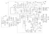
- FIGS. 7A-Bis a diagram of a fluid expansion system used in a Rankine cycle in accordance with some embodiments.
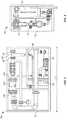
- FIG. 8is a quarter-sectional perspective view of a turbine generator apparatus in accordance with some embodiments.
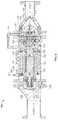
- FIG. 9is a cross-sectional view of the turbine generator apparatus of FIG. 8 .
- FIG. 10is a cross-section view of a portion of the turbine generator apparatus of FIG. 8 .
- FIG. 11is a diagram of a turbine generator apparatus used in a fluid expansion system to generate electrical power, in accordance with some embodiments.
- FIG. 12is a diagram of a heat source for a working fluid in a Rankine cycle, in accordance with some embodiments.
- FIG. 13is a perspective view of fluid cycle to generate electrical energy using a turbine generator apparatus, in accordance with some embodiments.
- a fluid expansion system 10may include a number of components that act upon a working fluid so as to generate kinetic energy from the expansion of the working fluid.
- the fluid expansion system 10can be part of a closed system, such as a Rankine Cycle or the like, in which the pressurized and heated working fluid is permitted to expand and release energy in a turbine generator apparatus 100 (described below in connection with FIGS. 8-10 ).
- a turbine generator apparatus 100described below in connection with FIGS. 8-10 .
- Such kinetic energycan then be converted, for example, to electrical energy that is supplied to a power electronics system or to an electrically powered machine.
- the heated and pressurized working fluidmay enter the turbine generator apparatus 100 through an inlet conduit 105 and thereafter expand as the fluid flows over a rotatable turbine wheel.
- the fluid expansion system 10can include a liquid separator 40 arranged upstream of the turbine generator apparatus 100 .
- the liquid separator 40may be configured to separate and remove a substantial portion of any liquid state droplets (or slugs) of working fluid that might otherwise pass into the turbine generator apparatus 100 .
- the fluid expansion system 10include a reservoir 20 that contains at least a portion of the working fluid in an expanded and cooled condition.
- the working fluid disposed in the reservoir 20may be in a liquid state after passing through a cooling stage of a Rankine cycle or the like.
- the reservoir 20has an internal volume that is accessed by a number of ports for the flow of working fluid into and out of the reservoir 20 .
- the reservoir 20is mounted to the package housing 12 of the system 10 so that the reservoir 20 can be transported contemporaneously with the turbine generator apparatus 100 .
- the reservoir 20may comprise a vertically oriented tank. In some circumstances, the vertically oriented tank can be more space efficient.
- the vertically oriented tankcan be used to increase the amount of liquid state working fluid that is arranged over the drain port of the reservoir 20 .
- the reservoirmay comprise a fluid container vessel having a different configuration, such as a horizontally oriented tank that may be used, for example, to reduce the overall height of the package housing 12 .
- the package housing 12 depicted in FIGS. 1-4may include outer panels that enclosed the components therein. Examples of such outer panels on the package housing 12 are shown and described in connection with FIGS. 5-6 . The outer panels are hidden from view in FIGS. 1-4 to show the components of the fluid expansion system 10 .
- the fluid expansion system 10may include a pump device 30 that is in fluid communication with the reservoir 20 .
- the pump device 30may be used to pressurize the working fluid and to direct the working fluid toward a heat source (described in more detail below).
- the pump device 30is mounted to the package housing 12 of the system 10 and is arranged below the reservoir so that the working fluid is gravity fed toward the pump device 30 .
- the pump devicemay include a motor 35 that provides operational power to the pump device. In these circumstances, rotation of the motor 35 drives the pump device 30 to force the working fluid toward the down stream components. As described in more detail below in connection with FIGS.
- the pump device 30may direct the working fluid to flow toward a heat source 60 , thereby causing the working fluid to be pressurized and heated.
- the heat source 60may be arranged outside of the package housing 12 of the fluid expansion system 10 .
- the working fluidmay return to the fluid expansion system 10 via a conduit that is connected to an inlet flow port (refer, for example, to the input port adjacent the liquid separator 40 as shown in FIGS. 1-4 ).
- the fluid expansion system 10also include a liquid separator 40 arranged upstream of the turbine generator apparatus 100 .
- the turbine generator apparatus 100receives the heated and pressurized working fluid so as to generate kinetic energy from the expansion of the working fluid therein.
- the turbine generator apparatus 100may be configured to operate when the heated and pressurized working fluid is in a gaseous state. In such circumstances, the likelihood of erosion or other damage to the turbine generator apparatus 100 may be increased when a portion of the working fluid includes droplets or “slugs” of fluid in a liquid state. Also, the efficiency of the turbine generator apparatus 100 may be decreased when a portion of the working fluid includes droplets or slugs in a liquid state.
- the liquid separator 40may be arranged upstream of the turbine generator apparatus so as to separate and remove a substantial portion of liquid state droplets or slugs of working fluid that might otherwise pass into the turbine generator apparatus 100 .
- the liquid separator 40may be in the form of a cyclone separator device, a coalescing membrane device, or the like.
- the liquid separator 40comprises a cyclone separator device that mechanically spins the working fluid to thereby centrifugally separate some or all of the liquid state droplets of working fluid.
- the liquid separator 40may comprise a cyclone separator device manufactured by R.P. Adams Company, Inc. of Tonawanda, N.Y.
- the liquid separatormay include a secondary reservoir 42 to which the separated liquid-state droplets or slugs or working fluid are directed.
- the secondary reservoir 42may be arranged below main body of the liquid separator so that the separated liquid-state fluid can be gravity fed toward the secondary reservoir 42 .
- the secondary reservoir 42may be in fluid communication with the previously described reservoir 20 , thereby permitting the separated liquid-state droplets to return to the working fluid contained in the reservoir 20 .
- the liquid separator 40can be arranged upstream of the turbine generator apparatus 100 in a manner such that the gaseous state working fluid can be passed to the turbine generator apparatus 100 while a substantial portion of any liquid-state droplets or slugs are removed and returned to the reservoir 20 .
- the liquid separator 40may be arranged upstream of the turbine generator apparatus 100 such that the liquid separator 40 is in direct fluid communication with the turbine generator apparatus 100 .
- the heated and pressurized working fluidmay be received by the separator inlet 45 , and the liquid separator 40 can act to remove a substantial portion of any liquid-state droplets or slugs of working fluid (as previously described).
- the separator outlet 49may be in direct fluid communication with the inlet 105 conduit of the turbine generator apparatus 100 . Accordingly, in this embodiment, at least the gaseous state portion of the heated and pressurized working fluid is passed directly from the separator outlet 45 to the inlet conduit 105 of the turbine generator apparatus 100 . Because a substantial portion of any liquid-state droplets or slugs are removed by the liquid separator 40 , the turbine generator apparatus 100 may be protected from damage caused by such liquid state working fluid.
- the liquid separator 40can serve as a reservoir volume to improve the system stability during transient conditions. For example, if the flow of the working fluid is initiated toward the turbine generator apparatus 100 before the working fluid has been sufficiently heated and pressurized, a random burst of liquid-state fluid flow may pass towards the turbine generator apparatus 100 .
- the liquid separator 40can serve as an accumulator device that protects the turbine generator apparatus 100 from such a burst of liquid-state fluid flow.
- the liquid separator 40may improve the system stability during transient conditions.
- the heated and pressurized working fluidmay enter the turbine generator apparatus 100 through the inlet conduit 105 and thereafter expand as the fluid flows over a rotatable turbine wheel (described below, for example, in connection with FIGS. 8-10 ).
- the rotation of the turbine wheel in the turbine generator apparatus 100is used to generate electrical energy that is then output from the fluid expansion system 10 .
- the working fluidmay exit the turbine generator apparatus 100 through an outlet conduit 109 .
- the expanded working fluid that exits the turbine generator apparatus 100may be directed to a cooling source.
- the expanded working fluidmay be directed to a condenser.
- the cooled and expanded working fluidmay be directed through a conduit to return to the reservoir 20 (refer, for example, in FIG. 1 ).
- the fluid expansion system 10is part of a closed loop Rankine cycle, as described in more detail below, some embodiments of the turbine generator apparatus 100 may serve as a single stage turbine expander with variable speed capability.
- the fluid expansion system 10can be constructed so that a user can readily access a number of the system components.
- the package housing 12 of the fluid expansion system 10may include a number of access panels 14 that can be opened by a user to access the reservoir 20 , the pump device 30 , the liquid separator 40 , the turbine apparatus 100 , and other components. Accordingly, in some circumstances, the inspection and maintenance of the fluid expansion system 10 can be performed with substantial disassembly.
- the fluid expansion system 10may include a control interface 15 (refer, for example, to FIG. 6 ) that provides the user with information on the performance and settings of the fluid expansion system.
- the control interfacemay include a display screen, a number of indicator meters, or a combination thereof so that a user can monitor the operation of the fluid expansion system 10 and (in some circumstances) adjust any settings or parameters of the system.
- the fluid expansion system 10can be constructed in a manner that provides simplified transportation to the desired installation location.
- the package housing 12 for the fluid expansion systemmay have overall dimensions that permit transport through a standard double-door passage.
- the package housing 12 of the fluid expansion system 10may have a width W (refer, for example, to FIG. 6 ) that is less than about 72 inches, less than about 50 inches, and preferably about 48 inches or less.
- the package housing 12 of the fluid expansion system 10may have a height H (refer, for example, to FIG. 6 ) that is less than about 80 inches and preferably about 78 inches or less.
- the fluid expansion system 10can be readily transported through a standard double-door passage to a desired installation location even if that location is accessible only through a standard double-door passage (having a size of about 72 inches by about 80 inches).
- the fluid expansion system 10can be readily partially disassembled for transport through a standard single-door passage (e.g., having a width of about 36 inches).
- the length L(refer, for example, to FIG. 3 ) of the packaging housing 12 may be affected by a number of factors, such as the size of the turbine generator apparatus 100 and the size of the reservoir 20 .
- the package housing 12may have a length L of about 180 inches or less, about 48 inches to about 150 inches, about 60 inches to about 130 inches, and in this embodiment about 112 inches.
- the fluid expansion system 10may be part of a closed loop cycle 50 , such as Rankine cycle, in which the heated and pressurized working fluid is expanded in the turbine generator apparatus 100 .
- the Rankine cyclemay comprise an organic Rankine cycle that employs an engineered working fluid.
- the working fluid in such a Rankine cyclemay comprise a high molecular mass organic fluid that is selected to efficiently receive heat from relatively low temperature heat sources.
- the turbine generator apparatus 100can be used to convert heat energy from a heat source into kinetic energy, which is then converted into electrical energy.
- the turbine generator apparatus 100may output electrical power in form of a 3-phase 60 Hz power signal at a voltage of about 400 VAC to about 480 VAC. Also, in some embodiments, the turbine generator apparatus 100 may be configured to provide an electrical power output of about 2 MW or less, about 50 kW to about 1 MW, and about 100 kW to about 300 kW, depending upon the heat source in the cycle and other such factors.
- the reservoir 20 of the fluid expansion system 10contains a portion of the working fluid for the closed loop cycle 50 .
- the working fluid disposed in the reservoirmay be in a liquid state after being expanded and cooled.
- the pump device 30is driven by the motor 35 so as to pressurize the working fluid to toward a heat source 60 .
- the pressurized working fluidis passed through a conduit toward the heat source so as to recover heat from the heat source 60 .
- at least a portion of the heat energy from the heat source 60is transferred to the working fluid using a heat exchanger 65 .
- the working fluidmay flow directly to the heat source 60 rather than receiving the heat from the intermediate heat exchanger 65 .
- the heat source 60may comprise, for example, an industrial application in which heat is a byproduct.
- the heat source 60may comprise an industrial application including, but not limited to, commercial exhaust oxidizers (e.g., a fan-induced draft heat source bypass system, a boiler system, or the like), refinery systems that produce heat, foundry systems, smelter systems, landfill flare gas and generator exhaust, commercial compressor systems, food bakeries, and food or beverage production systems.
- the fluid expansion system 10can be used to recover waste heat from industrial applications and then to convert the recovered waste heat into electrical energy.
- the heat energycan be recovered from geo-thermal heat sources and solar heat sources.
- the heated and pressurized working fluidreturns to the fluid expansion system 10 and is directed toward the turbine generator apparatus 100 .
- the liquid separator 40is arranged upstream of the turbine generator apparatus 100 , so the heat and pressurized working fluid passes through the liquid separator 40 before passing to the turbine generator apparatus 100 .
- the liquid separator 40may be arranged upstream of the turbine generator apparatus so as to separate and remove a substantial portion of any liquid state droplets or slugs of working fluid that might otherwise pass into the turbine generator apparatus 100 .
- the liquid separator 40includes a secondary reservoir 42 to which the separated liquid-state droplets or slugs or working fluid are directed.
- the secondary reservoir 42may be in fluid communication with the previously described reservoir 20 , thereby permitting the separated liquid-state droplets to return to the working fluid contained in the reservoir 20 . Because a substantial portion of any liquid-state droplets or slugs are removed by the liquid separator 40 , the turbine generator apparatus 100 may be protected from damage caused by such liquid state working fluid. In addition, the liquid separator 40 may improve the system stability during transient conditions (as previously described in connection with FIGS. 1-4 ).
- the gaseous state working fluidmay enter the turbine generator apparatus 100 after exiting the liquid separator 40 .
- the heat and pressurized working fluidcan thereafter expand as the fluid flows over a rotatable turbine wheel (described below, for example, in connection with FIGS. 8-10 ).
- the rotation of the turbine wheel in the turbine generator apparatus 100is used to generate electrical energy that is then output from the fluid expansion system 10 .
- the rotation of the turbine wheelcauses rotation of a rotor carrying a magnet device 150 within an electric generator device 160 (refer, for example, to FIGS. 8-10 ).
- the electric generator device 160may include electronic components used to configure and modify the electrical power generated.
- the turbine generator apparatus 100may output electrical power in form of a 3-phase 60 Hz power signal at a voltage of about 400 VAC to about 480 VAC.
- the electrical components of the generator device 160can regulate the electrical power output, thereby permitting the turbine generator apparatus 100 to serves as a single stage turbine expander with variable speed capability.
- the expanded working fluid that exits the turbine generator apparatus 100may be directed toward a cooling source 80 ( FIG. 7B ).
- the expanded working fluidis passed through a conduit toward the cooling source 80 so as to condense working fluid into a liquid state.
- the cooling source 80includes a condenser 85 that removes excess heat from the working fluid.
- the working fluidmay flow directly to the cooling source 80 (e.g., a cooling tower, a forced-air radiator system, or the like) rather than removing the heat from the working fluid using the condenser 85 .
- the cooled and expanded working fluidmay be directed through a conduit to return to the reservoir 20 ( FIG. 7A ).
- the fluid expansion system 10may be equipped with a dual control valve system 70 that provides flow control during transient flow conditions, protection for the turbine generator apparatus 100 , and efficient power output from the turbine generator apparatus 100 .
- the dual control valve system 70includes a first valve 72 a that operates as a through-flow valve to the turbine generator apparatus 100 and a second valve 72 b that operates as a bypass valve.
- the first and second valves 72 a - bcan be actuated so that one is fully open while another is fully closed.
- the second valve 72 be.g., the bypass valve
- the turbine generator apparatus 100is not exposed to the working fluid that is not fully heated to the desired temperature (e.g., some of which may still be in a liquid state), but the working fluid is permitted to cycle through the bypass valve 72 b for repeated heating cycles (e.g., the condenser 85 may be set to remove little or not heat from the working fluid during this “cooking up” process).
- the first valve 72 amay be set to fully open while the second valve is fully closed. In these circumstances, the bypass valve 72 b is closed and the heated and pressurized working fluid pass to the turbine generator apparatus 100 as previously described.
- the first and second valves 72 a - b of the dual control valve system 70may operate in unison so as to provide protection for the turbine generator apparatus during transient flow conditions and to provide efficient power output from the turbine generator apparatus 100 .
- the first valve 72 ais linked to the second valve 72 b so that actuation of one valve results in actuation of the other.
- the first valve 72 a and second valve 72 bmay be coupled to the same actuator device (e.g., a servo actuator, a hydraulic actuator, a pneumatic actuator, a hand-operated lever, or the like) so that a user can signal the actuator device to adjust the two valves 72 a - b in unison.
- first valve 72 amay have a first actuator and the second valve 72 b may have a second actuator, both of which operate in response to control signals from the same controller device.
- first and second valves 72 a - bmay comprise actuator-controlled butterfly valves that control the flow path of the working fluid (as depicted, for example, in FIG. 2 ).
- the turbine generator apparatus 100can generate kinetic energy from expansion of the working fluid.
- the fluid expansion systemcan be part of a closed system, such as a Rankine Cycle or the like, in which a pressurized and heated working fluid is permitted to expand and release energy in the turbine generator apparatus 100 .
- the heated and pressurized working fluidmay enter the turbine generator apparatus 100 through an inlet conduit 105 and thereafter expand as the fluid flows over a rotatable turbine wheel 120 .
- the working fluidis then directed to an outlet side 125 (refer to FIG. 10 ) of the turbine wheel 120 so as to flow axially through a body casing 107 and toward an outlet conduit 109 .
- the turbine wheel 120can be configured to rotate as the working fluid expands and flows toward the outlet side 125 of the turbine wheel 120 .
- the turbine wheel 120is a shrouded turbine wheel that includes a number of turbine blades 122 that translate the force from fluid acting against the blades 122 into the rotational motion of the turbine wheel 120 .
- the shroudcan be omitted and/or different configurations of turbine wheels can be used.
- the working fluidcan flow through the turbine wheel inlet 124 located proximate to an input side 126 (refer to FIG. 10 ) of the turbine wheel 120 , act upon the turbine blades 122 , and exit to the outlet side 125 of the turbine wheel.
- the outlet side 125 of the turbine wheel 120includes the region extending from proximate the outlet face of the turbine wheel 120 and toward the outlet conduit 109 .
- the turbine wheel 120is shaft mounted and coupled to a rotor 140 .
- the rotor 140may include a magnet 150 .
- the turbine wheel 120is driven to rotate by the expansion of the working fluid in the turbine generator apparatus 100 , and the rotor 140 (including the magnet 150 ) rotate in response to the rotation of the turbine wheel 120 .
- the turbine wheel 120is directly coupled to the rotor 140 , for example, by fasteners, rigid drive shaft, welding, or other manner.
- the turbine wheel 120can be indirectly coupled to the rotor 140 , for example, by a gear train, cutch mechanism, or other manner.
- two bearing supports 115 and 145are arranged to rotatably support the turbine wheel 120 relative to the body casing 107 .
- one or more of the bearing supports 115 or 145can include ball bearings, needle bearings, magnetic bearings, journal bearings, or other.
- the first and second bearing supports 115 and 145comprise magnetic bearings having operability similar to those described in U.S. Pat. No. 6,727,617 assigned to Calnetix Inc. The disclosure of U.S. Pat. No. 6,727,617 describing the features and operation of magnetic bearing supports is incorporated by reference herein.
- the first bearing support 115is mounted to a frame structure 116 on the input side 126 of the turbine wheel 120
- the second bearing support 145is mounted to a second frame structure 146 on the outlet side 125 of the turbine wheel 120 .
- the turbine wheel 120 and the rotor 140may be axially aligned and coupled to one another so as to collectively rotate about the axis of the bearing supports 115 and 145 . Accordingly, both the turbine wheel 120 and the rotor 140 can be supported in a non-cantilevered manner by the first and second bearing supports 115 and 145 .
- the turbine generator apparatus 100may include one or more backup bearing supports.
- the first and second bearing supports 115 and 145may comprise magnetic bearings that operate with electrical power.
- first and second backup bearings 119 and 149may be employed to rotatably support the turbine wheel 120 during that period of time.
- the first and second backup bearing supports 119 and 149may comprise ball bearings, needle bearings, journal bearings, or the like.
- the first backup bearing support 119includes ball bearings that are arranged near the first magnetic bearing support 115 .
- the second backup bearing support 149includes ball bearings that are arranged near the second magnetic bearing support 145 .
- the first and second backup bearing supports 119 and 149would continue to support both the turbine wheel 120 and the rotor 140 in a non-cantilevered manner.
- the turbine generator apparatus 100may be configured to generate electricity in response to the rotation of the driven member 150 .
- the magnet 150may comprise a permanent magnet that rotates within an electric generator device 160 .
- the electric generator device 160may include a stator 162 in which electrical current is generated by the rotation of the magnet 150 therein.
- the stator 162may include a plurality of a conductive coils used in the generation of electrical current.
- the stator 162 and other components of the electric generator device 160may produce heat as a byproduct during the generation of electrical current.
- the heat byproductcan be dissipated by flow of the working fluid exiting to the outlet side 125 of the turbine wheel 120 .
- the electrical power generated by the rotation of the magnet 150 within the stator 162can be transmitted to a generator electronics package arranged outside of the body casing 107 .
- the electrical power from the stator 162can be directed to one or more electrical connectors 167 for transmission to the electronics package, which then configures the electrical power to selected settings.
- the power outputcan be configured to provide useable electrical power, including either AC or DC power output at a variety of voltages.
- the generator electronics packagemay be used to output a 3-phase 60 Hz power output at a voltage of about 400 VAC to about 480 VAC, preferably about 460VAC.
- the generator electronics packagemay be used to output a DC voltage of about 12 V to about 270 V, including selected outputs of 12 V, 125 V, 250 V, and 270 V.
- the electrical power outputmay be selected at other settings, including other phases, frequencies, and voltages.
- the turbine generator apparatus 100can be used to generate power in a “stand alone” system in which the electrical power is generated for use in an isolated network (e.g., to power an isolated machine or facility) or in a “grid tie” system in which the power output is linked or synchronized with a power grid network (e.g., to transfer the generated electrical power to the power grid).
- a “stand alone” systemin which the electrical power is generated for use in an isolated network (e.g., to power an isolated machine or facility) or in a “grid tie” system in which the power output is linked or synchronized with a power grid network (e.g., to transfer the generated electrical power to the power grid).
- the turbine generator apparatus 100may include a number of longitudinally extending fins 170 .
- the fins 170may support the stator 162 in relation to the rotor 140 and direct the working fluid axially through the body casing 107 .
- the working fluidcan exit to the outlet side 125 of the turbine wheel 120 and be directed by a contoured surface 142 of the rotor 140 toward the longitudinal fins 170 .
- the longitudinal fins 170may serve as cooling fins that shunt at least a portion of the heat byproduct from the stator 162 to the longitudinal fins 170 for subsequent heat dissipation by the fluid flow.
- the working fluidpasses along components of the electrical generator device 160 so as to dissipate heat therefrom.
- the working fluidis directed to flow over the stator 162 , as well as, between the stator 162 and rotor 140 .
- the electrical generator device 160may include a number of electronic components (including the stator 162 ) that produce significant heat during operation, so dissipation of such heat can reduce the likelihood of component failure. As shown in FIGS.
- the permanent magnet 150 and the electrical generator device 160are arranged on the outlet side 125 of the turbine wheel 120 , the working fluid that exits the turbine wheel 120 can be used to cool the components of the electrical generator device 160 , thereby reducing the need for an external cooling system for the electrical generator device 160 .
- the inlet conduit 105can be a tubular structure that receives the heated and pressurized working fluid and directs the working fluid toward the input side 126 of the turbine wheel 120 .
- the inlet conduit 105can be mounted to the body casing 107 using a number fasteners that extend through adjacent flange portions. As such, the inlet conduit 105 can be removed from the body casing 107 so as to access the components on the input side 126 of the turbine wheel 120 .
- the inlet conduit 105can be removed to provide service access to components such as a flow diverter cone 110 , the first bearing support 115 , and the first backup bearing support 119 that are disposed on the input side 126 of the turbine wheel 120 .
- componentssuch as a flow diverter cone 110 , the first bearing support 115 , and the first backup bearing support 119 that are disposed on the input side 126 of the turbine wheel 120 .
- such accesscan be achieved without necessarily removing the turbine wheel 120 from the turbine apparatus 100 .
- the flow diverter cone 110is arranged to extend into a portion of the inlet conduit 105 so as to direct the working fluid toward the turbine wheel inlet 124 disposed near the input side 126 of the turbine wheel 120 .
- the flow diverter cone 110may include a number of pre-swirl vanes 112 that impose a circumferential flow component to the inlet fluid flow. As such, when the working fluid flows into the turbine wheel inlet 124 , the flow may have a circumferential swirl component that is at least partially similar to the rotational direction of the turbine wheel 120 .
- the pre-swirl vanes 112may be fixedly mounted to the flow diverter cone 110 at a predetermined angle so as to provide the desired tangential flow component.
- the pre-swirl vanes 112can be adjustably mounted to the flow diverter cone 110 so that the angle of the vanes 112 can be adjusted (e.g., by movement of an actuator 163 , such as a hydraulic or electrical actuator coupled to the vanes 112 ) to vary the pre-swirl angle of all vanes 112 in unison according to varying fluid flow conditions.
- the flow diverter cone 110can house elements of the system, for example, one or more actuators 163 and other components.
- pre-swirl vanes 112are depicted as being mounted to the diverter cone 110 in this embodiment, the pre-swirl vanes 112 can be fixedly mounted or adjustably mounted to the inlet conduit 105 near an inducer channel 117 to provide the desired tangential flow of the working fluid.
- the working fluidflows from the pre-swirl vanes 112 and into the inducer channel 117 that directs the working fluid toward the turbine wheel inlet 124 .
- the turbine wheel inlet 124is a radial inflow inlet disposed near the input side 126 of the turbine wheel 120 .
- the inducer channel 117may direct the working fluid to flow radially toward the turbine wheel inlet 124 (with the tangential flow component imposed by the pre-swirl vanes 112 ).
- the working fluidmay pass through an inlet nozzle device 118 that borders the periphery of the turbine wheel inlet 124 .
- the inlet nozzle device 118may have adjustable inlet nozzle geometry in which the inlet nozzle can be adjusted by one or more actuators.
- the flow diverter cone 110can be accessed for service or maintenance by removing the inlet conduit 105 (without necessarily removing the turbine wheel 120 ).
- the inlet nozzle device 118can be accessed for service or maintenance by removing the inlet conduit 105 and the first frame structure 116 (again, without necessarily removing the turbine wheel 120 ).
- the working fluidWhen the working fluid flows into the turbine wheel inlet 124 , the working fluid acts upon the turbine blades 122 so as to impose a rotational force upon the turbine wheel 120 .
- the turbine wheel 120that rotates about the wheel axis as the working fluid expands and flows toward the outlet side 125 of the turbine wheel 120 .
- the working fluidmay be pressurized and heated (in this example, to a temperature of about 230° F.) as it enters the inlet conduit 105 and thereafter may expand as it flows over the turbine wheel 120 and exits to the outlet side 125 (in this example, at a temperature of about 120° F.).
- the temperatures of the working fluid in the pressurized and heated state and the expanded statemay be different from the previous example.
- the working fluid temperatures in the pressurized and heated state and in the expanded statemay be selected based on a number of factors, such as the specific application in which the turbine generator apparatus 100 is used, the properties of the working fluid, and the like.
- At least a portion of the energy released from the expansion of the working fluidcan be converted into kinetic energy in the form of rotation of the turbine wheel 120 .
- the turbine wheel 120is a shrouded turbine wheel that includes a number of turbine blades 122 that translate the force from the working fluid acting against the blades 122 into the rotational motion of the turbine wheel 120 .
- the turbine blades 122can extended from the contoured hub of the turbine wheel 120 to the wheel shroud 123 and may be angled or contoured so as to impose a rotational force on the turbine wheel 120 as the working fluid acts against the blades 122 .
- the working fluidcan flow through the turbine wheel inlet 124 located proximate to the input side 126 of the turbine wheel, act upon the turbine blades 122 , and exit to the outlet side 125 of the turbine wheel 120 (e.g., the region extending from proximate the outlet face of the turbine wheel 120 and toward the outlet conduit 109 ).
- the turbine wheel 120can be arranged in the turbine generator apparatus 100 so that the driven member 150 is on the outlet side 125 of the turbine wheel 120 (rather than on the input side 126 of the turbine wheel 120 ).
- the outlet flow of working fluid to the outlet side 125 of the turbine wheel 120is directed toward the rotor 140 and the driven member 150 .
- Such an arrangement of the turbine wheel 120 and the driven member 150may provide a number of features that are useful in the construction, operation, and maintenance of the turbine generator apparatus 100 .
- the arrangement of the turbine wheel 120permits the turbine wheel 120 to be supported by bearing supports both the input side 126 and the outlet side 125 (e.g., including the region extending toward the outlet conduit 109 ).
- the turbine wheel 120can be rotationally supported by the first bearing support 115 ( FIG. 10 and FIG. 9 ) and the second bearing support 145 ( FIG. 9 ).
- the first bearing support 115is arranged on the input side 126 of the turbine wheel 120 so as to support the turbine wheel 120 relative to the first frame structure 116 and the body casing 107 of the turbine generator apparatus 100 .
- the turbine wheel 120can rotate about the axis of the first bearing support 115 .
- the turbine wheel 120is not necessarily overhung from the first bearing support 115 in a cantilever fashion (e.g., with no bearing support on the one of the turbine wheel). Rather, in this embodiment, the second bearing support 145 ( FIG. 2 ) is arranged on the outlet side 125 of the turbine wheel 120 (here, residing at an end of the rotor 140 opposite the turbine wheel 120 and within the region extending toward the outlet conduit 109 ) so as to support the turbine wheel 120 relative to the second frame structure 146 and the body casing 107 of the turbine generator apparatus 100 . Accordingly, the turbine wheel 120 can be rotatably mounted between the first bearing support 115 on the input side 126 and the second bearing support 145 on the outlet side 125 of the turbine wheel 120 . In such circumstances, the turbine wheel 120 (and the rotor 140 in this embodiment) can be supported in a non-cantilevered fashion.
- Such a configuration of the bearing supports 115 and 145 on both the input side 126 and the outlet side 125 of the turbine wheelcan provide an environment that is favorable to rotordynamic operation and lubrication.
- employing bearing supports on opposing sides of the turbine wheel 120may provide more uniform lubrication and load distribution along the rotational interfaces of the bearing supports (as compared to an overhung turbine wheel that is cantilevered from a bearing support).
- such a configurationcan improve temperature control of the rotational interfaces.
- the arrangement of the turbine wheel 120 in the turbine generator apparatus 100can reduce the time and disassembly operations normally required for inspection and service of the bearing supports.
- the bearing supports 115 and 145can be accessed for inspection and servicing without necessarily removing the turbine wheel 120 from the turbine apparatus 100 .
- the first bearing support 115(and, in this embodiment, the first backup bearing support 119 ) can be readily accessed by removing the inlet conduit 105 and the flow diverter cone 110 while the turbine wheel 120 remains generally in place. Because the inlet conduit 105 and flow diverter cone 110 can be comparatively smaller and lighter weight than conventional cast scrolls, it is easier to access the turbine wheel 120 and first bearing supports 115 .
- the second bearing support 145can be readily accessed by removing the outlet conduit 109 and a cap portion of the second frame structure 146 (again, while the turbine wheel 120 remains generally in place).
- the arrangement of the turbine wheel 120 in the turbine generator apparatus 100permits the fluid outflow to the outlet side 125 of the turbine wheel to be directed toward the stator 162 , rotor 140 , and/or other components.
- the working fluidcan be used as a heat dissipation flow after it has expanded (and thereby cooled).
- the working fluidcan dissipate heat from the electrical generator device 160 , including the stator 162 and other components.
- the working fluidexits the turbine wheel 120 into an exhaust conduit 130 , which includes a contoured surface to guide the expanded working fluid.
- the fluid flow that exits to the outlet side 125 of the turbine wheel 120may be directed in a generally axial direction toward the rotor 140 and stator 162 , which are arranged along the outlet side 125 of the turbine wheel 120 .
- at least a portion of the flow of the working fluidmay continue in the generally axial direction so as to flow directly over the stator 162 (e.g., along the outside of the stator 162 and along the longitudinal fins 170 ).
- At least a portion of the flow of the working fluidmay continue in the generally axial direction so as to flow between the rotor 140 and the stator 162 . Accordingly, some or all of the working fluid can be directed to flow over and dissipate heat from components of the electrical generator device 160 .
- the rotor 140may include a contoured surface 142 that redirects some or all of the fluid flow at least partially in a radial direction toward the longitudinal fins 170 , which then guide the working fluid at least partially in an axial direction.
- some or all of the working fluidcan be directed by the contoured surface 142 and the exhaust conduit 130 so as to flow over particular components of the electrical generator device 160 .
- the driven member 150 on the outlet side 125 of the turbine wheel 120facilitates the use of the expanded working fluid as a heat dissipation medium.
- the heat dissipation flow provided by the expanded working fluidmay reduce or eliminate the need for an external cooling system for the rotor 140 and/or stator 162 (and other components of the electrical generator device 160 ).
- the expanded working fluidmay flow along the longitudinal fins 170 at a rate so as to cool the stator 162 without employing an external cooling system to remove heat from the stator 162 .
- the arrangement of the turbine wheel 120 in the turbine generator apparatus 100provides for the use of seals 113 and 133 , which can serve to inhibit leakage of the working fluid out of the flow path.
- the arrangement of the turbine wheel 120permits the seals 113 and 133 to be readily accessed for inspection and service.
- the first seal 113can be disposed on the input side 126 along an outer annular surface of the turbine wheel 120 .
- the first seal 113can inhibit leakage of working fluid passing from the nozzle device 118 to a reaction pressure reservoir 137 , and such leakage reduction can be used to direct the working fluid to the wheel inlet 124 .
- the second seal 133can be disposed near the outlet side 125 of the turbine wheel along an outer annular surface of the wheel shroud 123 .
- the second seal 133can inhibit leakage of working fluid passing from the nozzle device 118 to the exhaust conduit 130 , and such leakage reduction can be used to reduce the likelihood of the working fluid bypassing the wheel inlet 124 .
- One or both of the first and second seals 113 and 133can be continuous-ring seals that are unitary and circumscribe the turbine wheel 120 .
- One or bothmay additionally, or alternatively, be labyrinth seals and may comprise a polymer material.
- the first and second seals 113 and 133have identical configurations.
- the turbine wheel 120can be pressure balanced. For example, when the working fluid exits to the outlet side 125 of the turbine wheel 120 , a low pressure region may be created near the turbine wheel outlet, which creates a thrust force is in the axial direction toward the outlet side 125 . To counter this low pressure region and the resulting thrust force, the reaction pressure reservoir 137 is arranged on the input side 126 of the turbine wheel 120 . The reaction pressure reservoir 137 may be in fluid communication with the exhaust conduit 130 so as to substantially equalize the pressure regions on both sides of the turbine wheel 120 , thereby providing a thrust balance arrangement for the turbine wheel 120 .
- the reaction pressure reservoir 137may be reduced by directing the working fluid in the reaction pressure reservoir 137 into a first channel 135 to a region on the interior of the flow diverter cone 110 . This region is in fluid communication with a second conduit 111 (e.g., shown as an external piping arrangement) that extends toward the exhaust conduit 130 .
- a second conduit 111e.g., shown as an external piping arrangement
- the fluid pressure in the reaction pressure reservoir 137may be equalized with the fluid pressure near the turbine wheel outlet in the exhaust conduit 130 , thereby neutralizing the thrust force that may other occur if the pressure on near the turbine wheel outlet was substantially different from the pressure in the reservoir 137 .
- Such a balancing of the thrust load imposed upon the turbine wheel 120may permit a substantial increase the permissible pressure drop across the turbine wheel 120 , which can thereby increase the maximum kinetic energy generated by the rotation of the turbine wheel 120 .
- the reaction pressure reservoir 137may be in fluid communication with the exhaust conduit 130 via internal channels through the first frame member 116 and the exhaust conduit (rather than using the external piping of the second conduit 111 ).
- the first channel 135may be in fluid communication with a second channel bored partially through the first frame structure 116 and partially through the wall of the exhaust conduit 130 .
- the reaction pressure reservoir 137can be in fluid communication with the exhaust conduit 130 so as to substantially equalize the pressure regions on both sides of the turbine wheel 120 .
- the arrangement of the turbine wheel 120 in the turbine generator apparatus 100can reduce the likelihood of leakage to or from the external environment. For example, because the flow from the outlet of the turbine wheel 120 is maintained within the turbine generator apparatus 100 rather than being exhausted outside of the system, the housing of the turbine generator apparatus 100 (including body casing 107 ) can be more readily hermetically sealed from the inlet conduit 105 to the outlet conduit 109 . Moreover, seepage of working fluid to the input side 126 of the turbine wheel 120 can simply reenter the working fluid flow path rather than leaking into the environment. For example, in the embodiment depicted in FIG. 10 , the working fluid flows through the inlet nozzle 118 to the turbine wheel 120 .
- any leakage of the working fluid toward the input side 126 of the turbine wheel 120would merely migrate into the reservoir 137 .
- the fluid that seeps into the reservoir 137can readily reenter into the working fluid flow path via the first and second conduits 135 and 111 (returning to the flow path near the exhaust conduit 130 ).
- the working fluid that was leaked to the input side 126 of the turbine wheel 120can reenter the flow of the working fluid without seeping into the external environment (e.g., outside the inlet conduit 105 , the body casing 107 , or flow path piping).
- the turbine wheel 120can provide a hermetically sealed turbine generator apparatus 100 .
- the hermetically sealed turbine generator apparatus 100may be useful, for example, when the working fluid is a regulated or hazardous fluid that should not be released into the external environment.
- the regulated or hazardous fluidsmay include engineered fluids that are used in a number of organic Rankine cycles.
- certain embodimentsmay use GENETRON 245 fa , a product of Honeywell International, Inc., as a working fluid.
- the working fluidmay comprise other engineered materials.
- the turbine generator apparatus 100can be employed in an organic Rankine cycle so as to reduce the likelihood of leaking the working fluid into the surrounding environment.
- the turbine generator apparatus 100can be used in a Rankine cycle 200 that recovers waste heat from one or more industrial processes.
- the Rankine cycle 200may comprise an organic Rankine cycle that employs an engineered working fluid to receive heat from an industrial application including, but not limited to, commercial exhaust oxidizers (e.g., a fan-induced draft heat source bypass system, a boiler system, or the like), refinery systems that produce heat, foundry systems, smelter systems, landfill flare gas and generator exhaust, commercial compressor systems, food bakeries, and food or beverage production systems.
- commercial exhaust oxidizerse.g., a fan-induced draft heat source bypass system, a boiler system, or the like
- refinery systemsthat produce heat, foundry systems, smelter systems, landfill flare gas and generator exhaust
- commercial compressor systemse.g., food bakeries, and food or beverage production systems.
- the heat energycan be recovered from geo-thermal heat sources and solar heat sources.
- the working fluid in such a Rankine cycle 200may comprise a high molecular mass organic fluid that is selected to efficiently receive heat from relatively low temperature heat sources.
- the turbine generator apparatus 100can be used to convert heat energy from a heat source into kinetic energy (e.g., rotation of the rotor 140 ), which is then converted into electrical energy.
- the turbine generator apparatus 100may output electrical power that is configured by an electronics package to be in form of 3-phase 60 Hz power at a voltage of about 400 VAC to about 480 VAC.
- alternative embodimentsmay out electrical power having other selected settings.
- the turbine generator apparatus 100may be configured to provide an electrical power output of about 2 MW or less, about 50 kW to about 1 MW, and about 100 kW to about 300 kW, depending upon the heat source in the cycle and other such factors.
- alternative embodimentsmay provide electrical power at other Wattage outputs.
- Such electrical powercan be transferred to a power electronics system and, in some embodiments, to an electrical power grid system.
- the electrical power output by the turbine generator apparatus 100can be supplied directly to an electrically powered facility or machine.
- the Rankine cycle 200may include a pump device 210 that pressurizes the working fluid.
- the pump device 210may be coupled to a reservoir 212 that contains the working fluid, and a pump motor 214 can be used to pressurize the working fluid.
- the pump device 210may be used to convey the working fluid to a heat source 220 of the Rankine cycle 200 .
- the heat source 220may include heat that is recovered from an existing process (e.g., an industrial process in which heat is byproduct). Examples of such an industrial process include commercial exhaust oxidizers (e.g., a fan-induced draft heat source bypass system, a boiler system, or the like) or commercial compressor systems (e.g., commercial compressor interstage cooling).
- the working fluidmay be directly heated by the existing process or may be heated in a heat exchanger in which the working fluid receives heat from a byproduct fluid of the existing process.
- the working fluidcan cycle through the heat source 220 so that a substantial portion of the fluid is converted into gaseous state. Accordingly, the working fluid is pressurized by the pump device 210 and then heated by the heat source 220 .
- the pressurized and heated working fluidmay pass from the heat source 220 to the turbine generator apparatus 100 .
- dual control valves 222 a - bmay be employed to control the flow of the working fluid to the turbine generator apparatus 100 (or to bypass the turbine generator apparatus 100 ).
- the first valve 222 amay be fully open while the second valve 22 b is fully closed, or vice versa.
- the first and second control valves 222 a - bmay be mechanically coupled to one another so as to operate in unison.
- an actuator device 224may be activated by a user or by a computer control system to contemporaneously adjust the first valve 222 a and the second valve 222 b between the respective opened and closed positions.
- the heated and pressurized working fluidmay be directed to the liquid separator 40 ( FIGS. 1 and 4A ).
- the liquid separator 40may be arranged upstream of the turbine generator apparatus 100 so as to separate and remove a substantial portion of any liquid state droplets or slugs of working fluid that might otherwise pass into the turbine generator apparatus 100 . Accordingly, the gaseous state working fluid can be passed to the turbine generator apparatus 100 while a substantial portion of any liquid-state droplets or slugs are removed and returned to the reservoir 212 .
- the heated and pressurized working fluidmay pass through the inlet conduit 105 and toward the turbine wheel 120 ( FIG. 8 ).
- the working fluidexpands as it flows across the turbine wheel 120 and into the body casing 107 , thereby acting upon the turbine wheel 120 and causing rotation of the turbine wheel 120 .
- the turbine generator apparatus 100can be included in a fluid expansion system in which kinetic energy is generated from expansion of the working fluid.
- the rotation of the turbine wheel 120is translated to the rotor 140 , which in this embodiment includes the magnet 150 that rotates within an electrical generator device 160 ( FIGS. 8-10 ).
- the kinetic energy of the turbine wheel 120is used to generate electrical energy.
- the electrical energy output from the electrical generator device 160can be transmitted via one or more connectors 167 (e.g., three connectors 167 are employed in this embodiment).
- the electrical energycan be communicated via the connectors 167 to a power electronics system 240 that is capable of modifying and storing the electrical energy.
- the power electronics system 240may be similar to power substation that is connected to an electrical power grid system.
- the turbine generator apparatus 100may be configured to provide an electrical power output of about 2 MW or less, about 50 kW to about 1 MW, and about 100 kW to about 300 kW, depending upon the heat source 220 , the expansion capabilities of the working fluid, and other such factors.
- the electrical energy output by the turbine generator apparatus 100can be supplied directly to an electrically powered facility or machine.
- the working fluidmay flow from the outlet conduit 109 of the turbine generator apparatus 100 to a condenser 250 .
- the condenser 250may include a motor 252 that is used to remove excess heat from the working fluid so that a substantial portion of the working fluid is converted to a liquid state.
- the motor 252may be used to force cooling airflow over the working fluid.
- the motor 252may be used to force a cooling fluid to flow in a heat exchange process with the working fluid.
- the fluidmay return to the reservoir 212 where it is prepared to flow again though the cycle 200 .
- the working fluid that passes through the turbine generator apparatus 100may recover waste heat from a commercial compressor interstage cooling process.
- a commercial compressor processmay employ interstage cooling in which the compressor fluid is cooled in a heat exchanger between one or more of the compression stages.
- the commercial compressor interstage coolingmay serve as the heat source 60 ( FIG. 4A ) or 220 ( FIG. 11 ) for the working fluid in the Rankine cycle.
- the commercial compressormay include a plurality of compressor stages 310 , 320 and 330 .
- a first heat exchanger 315may be arranged between the first and second compressor stages 310 and 320 so as to remove heat from the compressor fluid.
- the working fluid of the Rankine cyclepasses through a first section 316 of the heat exchanger 315 to receive a portion of the heat dissipated from the compressor fluid flow.
- the compressor fluidmay require further cooling, so a coolant fluid may pass through a second section 318 of the heat exchanger 315 to further dissipate any excess heat from the compressor fluid. After removing the excess heat from the compressor fluid, the coolant fluid may be directed to a cooling tower or the like. As shown in FIG.
- the first section 316 and the second section 318may be isolated from one another so that the working fluid of the Rankine cycle receives the heat from the compressor fluid as it initially exits from the first compressor stage 310 .
- the first and second sections 316 and 318 of the heat exchanger 315can be independently controlled. As such, the flow of the coolant fluid through the second section 318 can be adjusted to increase or decrease the overall amount of heat that is removed from the compressor fluid, thereby providing fine tuned control of the compressor fluid temperature while enabling the working fluid of the Rankine cycle to receive a substantial amount of heat.
- the working fluid that is heated in the first heat exchanger 315may be directed to a second heat exchanger 325 arranged between the second compressor stage 320 and the third compressor stage 330 . Similar to the first heat exchanger 315 , the second heat exchanger 325 may be subdivided into two sections 326 and 328 .
- the working fluid of the Rankine cyclepasses through the first section 326 of the heat exchanger 325 to receive a portion of the heat dissipated from the compressor fluid flow after the second compressor stage 320 .
- the coolant fluidmay pass through a second section 318 of the heat exchanger 325 to further dissipate any excess heat from the compressor fluid.
- the coolant fluidmay be directed to a cooling tower or the like. Similar to the previously described heat exchange 315 , the first section 326 and the second section 328 of the second heat exchanger 325 may be isolated from one another so that the working fluid of the Rankine cycle receives the heat from the compressor fluid as it initially exits from the second compressor stage 320 .
- the working fluid of the Rankine cyclecan be incrementally heated by a series of heat exchangers 315 and 325 arranged after the compressor stages 310 and 320 of a commercial compressor interstage cooling process.
- a series of heat exchangers 315 and 325arranged after the compressor stages 310 and 320 of a commercial compressor interstage cooling process.
- Such a processpermits the waste heat from an industrial process to be recovered and converted into electrical energy (e.g., by expansion of the working fluid in the turbine generator apparatus 100 ).
- the electrical energy generated by the turbine generator apparatus 100can be used to at least partially power the industrial process that generates the heat (e.g., the electrical power can be used to at least partially power the commercial compressor system).
- the kinetic energy from the rotation of the turbine wheel 120 in the turbine generator apparatus 100can be used to mechanically power the commercial compressor system.
- the turbine wheel 120 in the turbine generator apparatus 100can be coupled to at least one of the compressor high-speed shafts to augment the power required to rotate the compressor high-speed shaft (e.g., in a multi-stage turbo compressor application).
- the plurality of compressor stages 310 , 320 and 330can be used to heat the working fluid in the Rankine cycle, it should be understood that (in other embodiments) only one of the compressor stages (e.g., stage 310 ) may be used as the heat source for the working fluid.
- the embodiments described in connection with FIG. 12include the commercial compressor interstage cooling process operating as the heat source 60 ( FIG. 4A ) or 220 ( FIG. 11 ) for the working fluid in the Rankine cycle. It should be understood that, in some embodiments, the Rankine cycle described in connection with FIG. 12 may employ a fluid expansion system other than the previously illustrated fluid expansion system 10 .
- the working fluid that passes through the turbine generator apparatus 100may recover waste heat from an industrial process 420 , such as a commercial exhaust oxidizer, in which heat is byproduct. Accordingly, the working fluid is pressurized by the pump device 30 and then heated in a heat exchange process with the high-temperature exhaust fluid of the industrial process 420 before passing to the turbine generator apparatus 100 .
- an industrial process 420such as a commercial exhaust oxidizer
- the Rankine cycle 400includes the fluid expansion system 10 , the industrial process 420 in which heat is byproduct (e.g., commercial exhaust oxidizer to the like), and a condenser 450 (e.g., an evaporative condenser or the like).
- the industrial process 430may include an exhaust stack 425 through which a heated exhaust fluid is expelled.
- the heated exhaust fluidmay be a byproduct of the industrial process 420 .
- the exhaust fluidmay pass into the exhaust stack 425 at a temperature of about 200° F. or more, about 250° F. or more, about 300° F. to about 800° F., about 350° F. to about 600° F., and in some embodiments at about 400° F.
- the Rankine cycle 400may incorporate the fluid expansion system 10 to recover at least a portion of the heat energy and generate electrical power therefrom.
- the working fluid that passes that passes through the turbine generator apparatus 100may be heated in a heat exchanger 427 arranged proximate to the exhaust stack 425 of the industrial process 420 .
- the exhaust stack 425 of the industrial process 420may serve as an evaporator or other heat source that transfers heat energy to the working fluid before the working fluid passes through the turbine generator apparatus 100 .
- the heat exchanger 427is disposed in the exhaust stack 427 so as to recover at least a portion of the heat energy from the exhaust fluid and to transfer that heat energy to the working fluid of the Rankine cycle 400 .
- the working fluid that is heated in the heat exchanger 427may be directed to the fluid expansion system 10 for passage through the liquid separator 40 and the turbine generator apparatus 100 .
- the turbine generator apparatus 100can be used to generate electrical energy from the heated and pressurized working fluid.
- the working fluid of the Rankine cycle 400can be heated by at least one heat exchanger 427 arranged at the exhaust stack 425 of the industrial process 420 (e.g., a commercial exhaust oxidizer process).
- the electrical energy generated by the turbine generator apparatus 100can be used to at least partially power the industrial process that generates the heat (e.g., the electrical power can be used to at least partially power the oxidizer system).
- the working fluidmay be directed to a condenser unit 450 of the Rankine cycle 400 .
- the condenser unit 450may comprise, for example, and evaporative condenser that outputs the working fluid in a cooled state (e.g., in a liquid state).
- the expanded and cooled working fluidis then directed to the reservoir 20 of the fluid expansion system 10 where it awaits passage through the pump 30 and to the heat exchange process. This fluid cycle can be repeated so as to recover the waste heat from the industrial process 420 and thereafter convert the heat energy into electrical energy (e.g., by expansion of the working fluid in the turbine generator apparatus 100 ).
- the embodiments described in connection with FIG. 13include the commercial exhaust oxidizer operating as the heat source 60 ( FIG. 4A ) or 220 ( FIG. 11 ) for the working fluid in the Rankine cycle. It should be understood that, in some embodiments, the Rankine cycle described in connection with FIG. 13 may employ a fluid expansion system other than the previously illustrated fluid expansion system 10
Landscapes
- Engineering & Computer Science (AREA)
- Mechanical Engineering (AREA)
- General Engineering & Computer Science (AREA)
- Chemical & Material Sciences (AREA)
- Combustion & Propulsion (AREA)
- Physics & Mathematics (AREA)
- Thermal Sciences (AREA)
- Engine Equipment That Uses Special Cycles (AREA)
Abstract
Description
Claims (20)
Priority Applications (3)
| Application Number | Priority Date | Filing Date | Title |
|---|---|---|---|
| US11/735,854US8839622B2 (en) | 2007-04-16 | 2007-04-16 | Fluid flow in a fluid expansion system |
| EP08745846.9AEP2147194B1 (en) | 2007-04-16 | 2008-04-15 | Transportable generator system |
| PCT/US2008/060324WO2008130915A2 (en) | 2007-04-16 | 2008-04-15 | Fluid flow in a fluid expansion system |
Applications Claiming Priority (1)
| Application Number | Priority Date | Filing Date | Title |
|---|---|---|---|
| US11/735,854US8839622B2 (en) | 2007-04-16 | 2007-04-16 | Fluid flow in a fluid expansion system |
Publications (2)
| Publication Number | Publication Date |
|---|---|
| US20080250789A1 US20080250789A1 (en) | 2008-10-16 |
| US8839622B2true US8839622B2 (en) | 2014-09-23 |
Family
ID=39852478
Family Applications (1)
| Application Number | Title | Priority Date | Filing Date |
|---|---|---|---|
| US11/735,854Active2029-06-09US8839622B2 (en) | 2007-04-16 | 2007-04-16 | Fluid flow in a fluid expansion system |
Country Status (3)
| Country | Link |
|---|---|
| US (1) | US8839622B2 (en) |
| EP (1) | EP2147194B1 (en) |
| WO (1) | WO2008130915A2 (en) |
Cited By (21)
| Publication number | Priority date | Publication date | Assignee | Title |
|---|---|---|---|---|
| US20130207396A1 (en)* | 2012-02-14 | 2013-08-15 | Kabushiki Kaisha Kobe Seiko Sho (Kobe Steel, Ltd.) | Power generation apparatus |
| US20130263594A1 (en)* | 2010-12-01 | 2013-10-10 | Ola Hall | Arrangement and method for converting thermal energy to mechanical energy |
| US20140001762A1 (en)* | 2010-12-24 | 2014-01-02 | Anayet Temelci-Andon | Waste-heat recovery system |
| US20140013749A1 (en)* | 2010-12-24 | 2014-01-16 | Anayet Temelci-Andon | Waste-heat recovery system |
| US20150184546A1 (en)* | 2013-04-09 | 2015-07-02 | Panasonic Intellectual Property Management Co., Ltd. | Rankine cycle device, expansion system and expansion machine |
| US11578615B1 (en) | 2021-12-28 | 2023-02-14 | Industrial Technology Research Institute | Turbo device and circulatory system |
| US11594937B1 (en) | 2022-04-07 | 2023-02-28 | Sapphire Technologies, Inc. | Process integration in electrical power generation |
| US11611263B1 (en) | 2022-04-28 | 2023-03-21 | Sapphire Technologies, Inc. | Electrical power generation |
| US11619140B1 (en) | 2022-04-08 | 2023-04-04 | Sapphire Technologies, Inc. | Producing power with turboexpander generators based on specified output conditions |
| US11686223B1 (en) | 2022-04-07 | 2023-06-27 | Sapphire Technologies, Inc. | Capturing and utilizing waste heat in electrical power generation |
| US11795873B1 (en) | 2022-09-07 | 2023-10-24 | Sapphire Technologies, Inc. | Modular design of turboexpander components |
| US11994115B2 (en) | 2022-05-26 | 2024-05-28 | Sapphire Technologies, Inc. | Turboexpander islanding operation |
| US12000291B2 (en) | 2022-09-27 | 2024-06-04 | Sapphire Technologies, Inc. | Hydrogen cooling turboexpander |
| US12027732B2 (en) | 2022-04-19 | 2024-07-02 | Sapphire Technologies, Inc. | Fuel cell temperature control |
| US12104493B2 (en) | 2022-04-08 | 2024-10-01 | Sapphire Technologies, Inc. | Producing power with turboexpander generators based on specified output conditions |
| US12212214B2 (en) | 2022-09-30 | 2025-01-28 | Sapphire Technologies, Inc. | Hydrogen applications for turboexpander machines |
| US12258887B2 (en) | 2022-07-25 | 2025-03-25 | Sapphire Technologies, Inc. | Cooling gas recovered from a well |
| US12286953B2 (en) | 2022-07-25 | 2025-04-29 | Sapphire Technologies, Inc. | Energy recovery from a gas well |
| US12316197B2 (en) | 2022-08-31 | 2025-05-27 | Sapphire Technologies, Inc. | Brake resistor design for controlling rotor speed during generator shutdown sequence |
| US12374963B2 (en) | 2022-07-28 | 2025-07-29 | Sapphire Technologies, Inc. | Turboexpander system with low voltage ride through control architecture |
| US12374960B2 (en) | 2022-11-03 | 2025-07-29 | Sapphire Technologies, Inc. | Hydrogen production using electrical power generated by gas pressure letdown |
Families Citing this family (41)
| Publication number | Priority date | Publication date | Assignee | Title |
|---|---|---|---|---|
| US7841306B2 (en)* | 2007-04-16 | 2010-11-30 | Calnetix Power Solutions, Inc. | Recovering heat energy |
| US8839622B2 (en)* | 2007-04-16 | 2014-09-23 | General Electric Company | Fluid flow in a fluid expansion system |
| US8616323B1 (en) | 2009-03-11 | 2013-12-31 | Echogen Power Systems | Hybrid power systems |
| JP5326745B2 (en)* | 2009-03-31 | 2013-10-30 | 株式会社Ihi | Turbine generator |
| WO2010121255A1 (en) | 2009-04-17 | 2010-10-21 | Echogen Power Systems | System and method for managing thermal issues in gas turbine engines |
| CN102575532B (en) | 2009-06-22 | 2015-03-18 | 艾克竣电力系统股份有限公司 | Systems and methods for temperature regulation of inlet gas |
| US9316404B2 (en) | 2009-08-04 | 2016-04-19 | Echogen Power Systems, Llc | Heat pump with integral solar collector |
| US8869531B2 (en) | 2009-09-17 | 2014-10-28 | Echogen Power Systems, Llc | Heat engines with cascade cycles |
| US8813497B2 (en) | 2009-09-17 | 2014-08-26 | Echogen Power Systems, Llc | Automated mass management control |
| US8794002B2 (en)* | 2009-09-17 | 2014-08-05 | Echogen Power Systems | Thermal energy conversion method |
| US8613195B2 (en) | 2009-09-17 | 2013-12-24 | Echogen Power Systems, Llc | Heat engine and heat to electricity systems and methods with working fluid mass management control |
| US8193659B2 (en)* | 2009-11-19 | 2012-06-05 | Ormat Technologies, Inc. | Power system |
| US8400005B2 (en) | 2010-05-19 | 2013-03-19 | General Electric Company | Generating energy from fluid expansion |
| US8739538B2 (en) | 2010-05-28 | 2014-06-03 | General Electric Company | Generating energy from fluid expansion |
| EP2630343B1 (en)* | 2010-09-14 | 2018-07-04 | Dresser-Rand Company | System and method of expanding a fluid in a hermetically-sealed casing |
| US8616001B2 (en) | 2010-11-29 | 2013-12-31 | Echogen Power Systems, Llc | Driven starter pump and start sequence |
| US8783034B2 (en) | 2011-11-07 | 2014-07-22 | Echogen Power Systems, Llc | Hot day cycle |
| US8857186B2 (en) | 2010-11-29 | 2014-10-14 | Echogen Power Systems, L.L.C. | Heat engine cycles for high ambient conditions |
| US8813500B2 (en)* | 2011-08-03 | 2014-08-26 | Dresser-Rand Company | Combined heat exchanger expander mounting system |
| WO2013055391A1 (en) | 2011-10-03 | 2013-04-18 | Echogen Power Systems, Llc | Carbon dioxide refrigeration cycle |
| US9689281B2 (en)* | 2011-12-22 | 2017-06-27 | Nanjing Tica Air-Conditioning Co., Ltd. | Hermetic motor cooling for high temperature organic Rankine cycle system |
| US9024460B2 (en) | 2012-01-04 | 2015-05-05 | General Electric Company | Waste heat recovery system generator encapsulation |
| US8984884B2 (en) | 2012-01-04 | 2015-03-24 | General Electric Company | Waste heat recovery systems |
| US9018778B2 (en) | 2012-01-04 | 2015-04-28 | General Electric Company | Waste heat recovery system generator varnishing |
| US9249691B2 (en) | 2012-01-06 | 2016-02-02 | General Electric Company | Systems and methods for cold startup of rankine cycle devices |
| US9091278B2 (en) | 2012-08-20 | 2015-07-28 | Echogen Power Systems, Llc | Supercritical working fluid circuit with a turbo pump and a start pump in series configuration |
| US9118226B2 (en) | 2012-10-12 | 2015-08-25 | Echogen Power Systems, Llc | Heat engine system with a supercritical working fluid and processes thereof |
| US9341084B2 (en) | 2012-10-12 | 2016-05-17 | Echogen Power Systems, Llc | Supercritical carbon dioxide power cycle for waste heat recovery |
| WO2014117074A1 (en) | 2013-01-28 | 2014-07-31 | Echogen Power Systems, L.L.C. | Process for controlling a power turbine throttle valve during a supercritical carbon dioxide rankine cycle |
| WO2014117068A1 (en) | 2013-01-28 | 2014-07-31 | Echogen Power Systems, L.L.C. | Methods for reducing wear on components of a heat engine system at startup |
| JP2016519731A (en) | 2013-03-04 | 2016-07-07 | エコージェン パワー システムズ エル.エル.シー.Echogen Power Systems, L.L.C. | Heat engine system with high net power supercritical carbon dioxide circuit |
| EP3066310B1 (en)* | 2014-03-05 | 2018-10-31 | Siemens Aktiengesellschaft | Flash tank design |
| EP2975739B1 (en)* | 2014-07-17 | 2017-10-18 | Siemens Aktiengesellschaft | Dynamo-electric machine with bearing assembly |
| US10570777B2 (en) | 2014-11-03 | 2020-02-25 | Echogen Power Systems, Llc | Active thrust management of a turbopump within a supercritical working fluid circuit in a heat engine system |
| US10883388B2 (en) | 2018-06-27 | 2021-01-05 | Echogen Power Systems Llc | Systems and methods for generating electricity via a pumped thermal energy storage system |
| CN111173583B (en)* | 2020-01-11 | 2020-08-28 | 哈尔滨学院 | A carbon dioxide power generation thermal energy conversion mechanical energy device |
| US11435120B2 (en) | 2020-05-05 | 2022-09-06 | Echogen Power Systems (Delaware), Inc. | Split expansion heat pump cycle |
| CA3201373A1 (en) | 2020-12-09 | 2022-06-16 | Timothy Held | Three reservoir electric thermal energy storage system |
| WO2023196522A1 (en)* | 2022-04-07 | 2023-10-12 | Sapphire Technologies, Inc. | Process integration in electrical power generation |
| WO2025010090A1 (en) | 2023-02-07 | 2025-01-09 | Supercritical Storage Company, Inc. | Waste heat integration into pumped thermal energy storage |
| US20250179929A1 (en)* | 2023-11-30 | 2025-06-05 | Sapphire Technologies, Inc. | Pressure control in a turboexpander |
Citations (160)
| Publication number | Priority date | Publication date | Assignee | Title |
|---|---|---|---|---|
| US2276695A (en) | 1939-02-25 | 1942-03-17 | Lavarello Ernesto | Steam turbine |
| US2409857A (en) | 1944-04-15 | 1946-10-22 | Westinghouse Air Brake Co | Linear generator |
| US2465761A (en) | 1943-12-08 | 1949-03-29 | Olive B Staude | Double-acting proportional pressure power amplifier |
| US2917636A (en) | 1957-06-10 | 1959-12-15 | Gen Electric | Frequency-regulated turbo generator |
| US3035557A (en) | 1959-07-23 | 1962-05-22 | Sulzer Ag | Method of cooling resuperheaters of a steam plant |
| US3060335A (en) | 1961-02-07 | 1962-10-23 | Garrett Corp | Fluid cooled dynamoelectric machine |
| US3064942A (en) | 1957-09-03 | 1962-11-20 | Thomas B Martin | Emergency ram air power supply |
| US3212477A (en)* | 1963-09-05 | 1965-10-19 | Combustion Eng | Forced flow steam generator and method of starting same |
| US3232050A (en) | 1963-03-25 | 1966-02-01 | Garrett Corp | Cryogenic closed cycle power system |
| US3349548A (en)* | 1964-01-22 | 1967-10-31 | C C Ind | Cyclone separator for separating steam from water |
| US3376857A (en)* | 1966-02-07 | 1968-04-09 | Robert J.S. Smith | Steam condensers |
| US3439201A (en) | 1965-10-06 | 1969-04-15 | Gen Motors Corp | Cooling arrangement for dynamoelectric machines |
| US3530836A (en) | 1967-07-13 | 1970-09-29 | Sulzer Ag | Forced through-flow steam generator |
| US3599424A (en)* | 1968-10-02 | 1971-08-17 | Gulf Oil Corp | Power conversion system |
| US3728857A (en) | 1971-06-22 | 1973-04-24 | Gates Rubber Co | Turbo-compressor-pump |
| US3830062A (en) | 1973-10-09 | 1974-08-20 | Thermo Electron Corp | Rankine cycle bottoming plant |
| US3943443A (en) | 1973-04-26 | 1976-03-09 | Toshiba Kikai Kabushiki Kaisha | Speed detectors |
| US3950950A (en)* | 1975-05-05 | 1976-04-20 | E. I. Du Pont De Nemours And Company | Rotary Rankine engine powered electric generating apparatus |
| US3999787A (en)* | 1972-04-17 | 1976-12-28 | Fast Load Control Inc. | Method of effecting fast turbine valving for improvement of power system stability |
| US4033141A (en) | 1974-09-05 | 1977-07-05 | Projectus Industriprodukter Ab | Method for thermal running of a heat pump plant and plant for carrying out the method |
| US4170435A (en) | 1977-10-14 | 1979-10-09 | Swearingen Judson S | Thrust controlled rotary apparatus |
| JPS5575502U (en) | 1978-11-20 | 1980-05-24 | ||
| US4260914A (en) | 1979-03-28 | 1981-04-07 | Digital Equipment Corporation | Differential linear velocity transducer |
| US4262495A (en)* | 1979-09-20 | 1981-04-21 | The Boeing Company | Cabin-air recirculation system powered by cabin-to-ambient pressure differential |
| US4262636A (en)* | 1978-10-03 | 1981-04-21 | Sulzer Brothers Limited | Method of starting a forced-flow steam generator |
| US4301375A (en) | 1980-01-02 | 1981-11-17 | Sea Solar Power, Inc. | Turbo-generator unit and system |
| JPS5768507A (en) | 1980-10-17 | 1982-04-26 | Mitsui Eng & Shipbuild Co Ltd | Rankine cycle generating apparatus |
| US4341151A (en) | 1979-12-11 | 1982-07-27 | Matsushita Seiko Co., Ltd. | Electric fan |
| US4358697A (en) | 1981-08-19 | 1982-11-09 | Siemens-Allis, Inc. | Two-pole permanent magnet synchronous motor rotor |
| US4362020A (en) | 1981-02-11 | 1982-12-07 | Mechanical Technology Incorporated | Hermetic turbine generator |
| US4415024A (en) | 1980-11-05 | 1983-11-15 | Joy Manufacturing Company | Heat exchanger assembly |
| US4463567A (en) | 1982-02-16 | 1984-08-07 | Transamerica Delaval Inc. | Power production with two-phase expansion through vapor dome |
| US4472355A (en)* | 1982-08-26 | 1984-09-18 | Westinghouse Electric Corp. | Concentrator apparatus |
| US4479354A (en) | 1979-08-20 | 1984-10-30 | Thomas Cosby | Limited expansion vapor cycle |
| US4512851A (en)* | 1983-02-15 | 1985-04-23 | Swearingen Judson S | Process of purifying a recirculating working fluid |
| US4544855A (en) | 1983-03-10 | 1985-10-01 | Bbc Brown, Boveri & Company Limited | Gas cooled alternating current machine |
| US4553397A (en) | 1981-05-11 | 1985-11-19 | Soma Kurtis | Method and apparatus for a thermodynamic cycle by use of compression |
| US4555637A (en) | 1982-07-26 | 1985-11-26 | Acd, Inc. | High speed turbogenerator for power recovery from fluid flow within conduit |
| US4558228A (en) | 1981-10-13 | 1985-12-10 | Jaakko Larjola | Energy converter |
| US4635712A (en) | 1985-03-28 | 1987-01-13 | Baker Robert L | Heat exchanger assembly for a compressor |
| US4659969A (en) | 1984-08-09 | 1987-04-21 | Synektron Corporation | Variable reluctance actuator having position sensing and control |
| US4738111A (en)* | 1985-12-04 | 1988-04-19 | Edwards Thomas C | Power unit for converting heat to power |
| US4740711A (en) | 1985-11-29 | 1988-04-26 | Fuji Electric Co., Ltd. | Pipeline built-in electric power generating set |
| US4748814A (en)* | 1985-07-05 | 1988-06-07 | Hitachi, Ltd. | Electric power generating plant |
| US4760705A (en) | 1983-05-31 | 1988-08-02 | Ormat Turbines Ltd. | Rankine cycle power plant with improved organic working fluid |
| JPS63129839U (en) | 1987-02-18 | 1988-08-24 | ||
| JPS63277443A (en) | 1987-05-07 | 1988-11-15 | Fuji Electric Co Ltd | Generator with built-in piping |
| US4838027A (en) | 1987-04-08 | 1989-06-13 | Carnot, S.A. | Power cycle having a working fluid comprising a mixture of substances |
| GB2225813A (en) | 1988-12-06 | 1990-06-13 | Michel Laine | Hydraulic turbine driving a generator |
| US4996845A (en) | 1988-08-26 | 1991-03-05 | Woo Taik Moon | Cooling, heating and power generating device using automobile waste heat |
| US5000003A (en) | 1989-08-28 | 1991-03-19 | Wicks Frank E | Combined cycle engine |
| US5003211A (en) | 1989-09-11 | 1991-03-26 | The United States Of America As Represented By The Administrator Of The National Aeronautics And Space Administration | Permanent magnet flux-biased magnetic actuator with flux feedback |
| EP0462724A1 (en) | 1990-06-07 | 1991-12-27 | General Electric Company | Integrated turbine generator |
| USD325080S (en) | 1990-03-20 | 1992-03-31 | Tatung Company Of America, Inc. | Desk fan |
| US5107682A (en) | 1986-12-11 | 1992-04-28 | Cosby Thomas L | Maximum ambient cycle |
| WO1993001397A1 (en) | 1991-07-11 | 1993-01-21 | Oy High Speed Tech. Ltd. | Method and apparatus for improving the efficiency of a small-size power plant based on the orc process |
| US5241425A (en) | 1991-07-19 | 1993-08-31 | Sony Corporation | Velocity sensor |
| US5263816A (en) | 1991-09-03 | 1993-11-23 | General Motors Corporation | Turbomachine with active tip clearance control |
| US5285123A (en) | 1992-04-06 | 1994-02-08 | Doryokuro Kakunenryo Kaihatsu Jigyodan | Turbo-generator |
| US5315197A (en) | 1992-04-30 | 1994-05-24 | Avcon - Advance Controls Technology, Inc. | Electromagnetic thrust bearing using passive and active magnets, for coupling a rotatable member to a stationary member |
| US5351487A (en) | 1992-05-26 | 1994-10-04 | Abdelmalek Fawzy T | High efficiency natural gas engine driven cooling system |
| US5481145A (en) | 1992-11-18 | 1996-01-02 | Anton Piller Gmbh & Co. Kg | Power recovery plant |
| US5514924A (en) | 1992-04-30 | 1996-05-07 | AVCON--Advanced Control Technology, Inc. | Magnetic bearing providing radial and axial load support for a shaft |
| US5531073A (en) | 1989-07-01 | 1996-07-02 | Ormat Turbines (1965) Ltd | Rankine cycle power plant utilizing organic working fluid |
| US5559379A (en) | 1993-02-03 | 1996-09-24 | Nartron Corporation | Induction air driven alternator and method for converting intake air into current |
| US5627420A (en) | 1994-12-16 | 1997-05-06 | Westinghouse Electric Corporation | Pump powered by a canned electric motor having a removable stator cartridge |
| US5640064A (en) | 1993-10-20 | 1997-06-17 | General Electric Company | Dynamoelectric machine and method for manufacturing same |
| US5672047A (en) | 1995-04-12 | 1997-09-30 | Dresser-Rand Company | Adjustable stator vanes for turbomachinery |
| US5671601A (en) | 1992-10-02 | 1997-09-30 | Ormat Industries, Ltd. | Geothermal power plant operating on high pressure geothermal fluid |
| US5743094A (en) | 1994-02-22 | 1998-04-28 | Ormat Industries Ltd. | Method of and apparatus for cooling a seal for machinery |
| US5780932A (en) | 1994-05-03 | 1998-07-14 | Gec Alsthom Electromecanique Sa | Electricity generating unit having a combined cycle and including a gas turbine and a steam turbine having a plurality of modules |
| US5818242A (en) | 1996-05-08 | 1998-10-06 | United Technologies Corporation | Microwave recess distance and air-path clearance sensor |
| US5852338A (en) | 1997-02-03 | 1998-12-22 | General Electric Company | Dynamoelectric machine and method for manufacturing same |
| US5894182A (en) | 1997-08-19 | 1999-04-13 | General Electric Company | Motor with rotor and stator core paired interlocks |
| US5942829A (en) | 1997-08-13 | 1999-08-24 | Alliedsignal Inc. | Hybrid electrical machine including homopolar rotor and stator therefor |
| US5990588A (en) | 1996-12-13 | 1999-11-23 | General Electric Company | Induction motor driven seal-less pump |
| US5994804A (en) | 1998-12-07 | 1999-11-30 | Sundstrand Corporation | Air cooled dynamoelectric machine |
| US6002191A (en) | 1998-06-19 | 1999-12-14 | General Electric Company | Paired interlocks for stacking of non-rotated lamination cores |
| US6018207A (en) | 1998-07-10 | 2000-01-25 | General Electric Company | Paired interlocks for flexible indexing of rotated stator cores |
| US6087744A (en) | 1997-08-26 | 2000-07-11 | Robert Bosch Gmbh | Electrical machine |
| US6130494A (en) | 1995-08-18 | 2000-10-10 | Sulzer Electroncis Ag | Magnetic bearing apparatus and a method for operating the same |
| US6148967A (en) | 1998-07-10 | 2000-11-21 | Alliedsignal Inc. | Non-contacting and torquer brake mechanism |
| US6167703B1 (en) | 1998-03-28 | 2001-01-02 | Daimlerchrysler Ag | Internal combustion engine with VTG supercharger |
| US6177735B1 (en) | 1996-10-30 | 2001-01-23 | Jamie C. Chapman | Integrated rotor-generator |
| US6191511B1 (en) | 1998-09-28 | 2001-02-20 | The Swatch Group Management Services Ag | Liquid cooled asynchronous electric machine |
| JP2001078390A (en) | 1999-09-02 | 2001-03-23 | Toshiba Corp | Rotating electric machine |
| US6223417B1 (en) | 1998-08-19 | 2001-05-01 | General Electric Corporation | Method for forming motor with rotor and stator core paired interlocks |
| US6250258B1 (en)* | 1999-02-22 | 2001-06-26 | Abb Alstom Power ( Schweiz) Ag | Method for starting up a once-through heat recovery steam generator and apparatus for carrying out the method |
| US6259166B1 (en) | 1998-10-30 | 2001-07-10 | Asea Brown Boveri Ag | Generator with double driving machinery |
| US6270309B1 (en) | 1998-12-14 | 2001-08-07 | Ghetzler Aero-Power Corporation | Low drag ducted Ram air turbine generator and cooling system |
| US6304015B1 (en) | 1999-05-13 | 2001-10-16 | Alexei Vladimirovich Filatov | Magneto-dynamic bearing |
| US6324494B1 (en) | 2000-06-16 | 2001-11-27 | General Electric Company | Method and system for modeling stator winding end-turn leakage reactance of an electric motor |
| US6325142B1 (en) | 1998-01-05 | 2001-12-04 | Capstone Turbine Corporation | Turbogenerator power control system |
| US6343570B1 (en) | 1997-08-25 | 2002-02-05 | Siemens Aktiengesellschaft | Steam generator, in particular waste-heat steam generator, and method for operating the steam generator |
| JP3271507B2 (en) | 1996-01-23 | 2002-04-02 | 株式会社村田製作所 | Electrode forming method for electronic component and masking device used for the method |
| US6388356B1 (en) | 1999-12-30 | 2002-05-14 | General Electric Company | Methods and apparatus for controlling electromagnetic flux in dynamoelectric machines |
| USD459796S1 (en) | 2001-08-10 | 2002-07-02 | Lakewood Engineering And Manufacturing Co. | Portable electric fan |
| US6437468B2 (en) | 2000-04-24 | 2002-08-20 | Capstone Turbine Corporation | Permanent magnet rotor cooling system and method |
| US6465924B1 (en) | 1999-03-31 | 2002-10-15 | Seiko Instruments Inc. | Magnetic bearing device and a vacuum pump equipped with the same |
| US6504337B1 (en) | 2001-06-08 | 2003-01-07 | General Electric Company | Motor modeling using harmonic ampere-turn saturation method |
| US20030074165A1 (en) | 2001-10-15 | 2003-04-17 | Saban Daniel M. | Method for optimizing strategy for electric machines |
| US6598397B2 (en) | 2001-08-10 | 2003-07-29 | Energetix Micropower Limited | Integrated micro combined heat and power system |
| WO2003100946A1 (en) | 2002-05-28 | 2003-12-04 | Emerson Electric Co. | Cooling jacket for electric machines |
| US6664680B1 (en) | 2000-12-20 | 2003-12-16 | Indigo Energy, Inc. | Flywheel device with active magnetic bearings |
| US6663347B2 (en) | 2001-06-06 | 2003-12-16 | Borgwarner, Inc. | Cast titanium compressor wheel |
| US20040020206A1 (en)* | 2001-05-07 | 2004-02-05 | Sullivan Timothy J. | Heat energy utilization system |
| US20040027011A1 (en) | 2002-07-24 | 2004-02-12 | Bostwick Peter K. | Optimized thermal system for an electric motor |
| US6692222B2 (en) | 2002-05-14 | 2004-02-17 | The Board Of Trustees Of The Leland Stanford Junior University | Micro gas turbine engine with active tip clearance control |
| US6700258B2 (en) | 2001-05-23 | 2004-03-02 | Calnetix | Magnetic thrust bearing with permanent bias flux |
| US6727617B2 (en) | 2002-02-20 | 2004-04-27 | Calnetix | Method and apparatus for providing three axis magnetic bearing having permanent magnets mounted on radial pole stack |
| US6777847B1 (en) | 1998-06-26 | 2004-08-17 | General Electric Company | Rotor core utilizing laminations having slots with dual direction skew portions |
| US6794780B2 (en) | 1999-12-27 | 2004-09-21 | Lust Antriebstechnik Gmbh | Magnetic bearing system |
| US20040189429A1 (en) | 2003-03-28 | 2004-09-30 | Saban Daniel M. | Liquid-cooled inductive devices with interspersed winding layers and directed coolant flow |
| US6856062B2 (en) | 2000-04-26 | 2005-02-15 | General Atomics | Homopolar machine with shaft axial thrust compensation for reduced thrust bearing wear and noise |
| US6876194B2 (en) | 2003-02-26 | 2005-04-05 | Delphi Technologies, Inc. | Linear velocity sensor and method for reducing non-linearity of the sensor output signal |
| US6880344B2 (en) | 2002-11-13 | 2005-04-19 | Utc Power, Llc | Combined rankine and vapor compression cycles |
| US20050093391A1 (en) | 2003-11-03 | 2005-05-05 | Mcmullen Patrick T. | Sleeveless permanent magnet rotor construction |
| US6897587B1 (en) | 2003-01-21 | 2005-05-24 | Calnetix | Energy storage flywheel with minimum power magnetic bearings and motor/generator |
| US6900553B2 (en) | 2000-11-30 | 2005-05-31 | Richard Julius Gozdawa | Gas turbomachinery generator |
| US6960840B2 (en) | 1998-04-02 | 2005-11-01 | Capstone Turbine Corporation | Integrated turbine power generation system with catalytic reactor |
| US6967461B1 (en) | 2004-08-31 | 2005-11-22 | Hamilton Sundstrand Corporation | North-south pole determination for carrier injection sensorless position sensing systems |
| US20050262848A1 (en) | 2004-05-28 | 2005-12-01 | Joshi Narendra D | Methods and apparatus for operating gas turbine engines |
| US6986251B2 (en) | 2003-06-17 | 2006-01-17 | Utc Power, Llc | Organic rankine cycle system for use with a reciprocating engine |
| US7019412B2 (en)* | 2002-04-16 | 2006-03-28 | Research Sciences, L.L.C. | Power generation methods and systems |
| US7042118B2 (en) | 2003-11-10 | 2006-05-09 | Calnetix | Permanent magnet rotor construction wherein relative movement between components is prevented |
| US7047744B1 (en) | 2004-09-16 | 2006-05-23 | Robertson Stuart J | Dynamic heat sink engine |
| US20060185366A1 (en) | 2005-02-22 | 2006-08-24 | Siemens Aktiengesellschaft | Thermal power plant |
| GB2405450B (en) | 2003-08-27 | 2006-09-06 | Freepower Ltd | Working energy recovery system including a turbine |
| US7125223B2 (en) | 2003-09-30 | 2006-10-24 | General Electric Company | Method and apparatus for turbomachine active clearance control |
| US7146813B2 (en) | 2002-11-13 | 2006-12-12 | Utc Power, Llc | Power generation with a centrifugal compressor |
| US20070018516A1 (en) | 2005-07-25 | 2007-01-25 | Hamilton Sundstrand | Internal thermal management for motor driven machinery |
| US20070056285A1 (en) | 2005-09-12 | 2007-03-15 | Brewington Doyle W | Monocoque turbo-generator |
| US20070063594A1 (en) | 2005-09-21 | 2007-03-22 | Huynh Andrew C S | Electric machine with centrifugal impeller |
| US7208854B1 (en) | 2006-03-09 | 2007-04-24 | Hamilton Sundstrand Corporation | Rotor cooling system for synchronous machines with conductive sleeve |
| JP2007127060A (en) | 2005-11-04 | 2007-05-24 | Ebara Corp | Drive system |
| US7225621B2 (en) | 2005-03-01 | 2007-06-05 | Ormat Technologies, Inc. | Organic working fluids |
| WO2007088194A2 (en) | 2006-02-02 | 2007-08-09 | Frank Eckert | Organic rankine cycle (orc) turbogenerator |
| US20070200438A1 (en) | 2006-02-24 | 2007-08-30 | General Electric Company | Methods and apparatus for using an electrical machine to transport fluids through a pipeline |
| US20070204623A1 (en) | 1998-08-31 | 2007-09-06 | William Rollins | High density combined cycle power plant process |
| US20080103632A1 (en) | 2006-10-27 | 2008-05-01 | Direct Drive Systems, Inc. | Electromechanical energy conversion systems |
| WO2008061271A1 (en) | 2006-11-23 | 2008-05-29 | Mahle König Kommanditgesellschaft Gmbh & Co | Method for converting heat energy and rotary vane piston motor |
| WO2008090628A1 (en) | 2007-01-26 | 2008-07-31 | Hitachi, Ltd. | Steam turbine type power generating apparatus and method of operating the same |
| US20080224551A1 (en) | 2007-03-15 | 2008-09-18 | Direct Drive Systems, Inc. | Cooling an Electrical Machine |
| US20080246281A1 (en) | 2007-02-01 | 2008-10-09 | Agrawal Giridhari L | Turboalternator with hydrodynamic bearings |
| US20080246373A1 (en) | 2007-04-05 | 2008-10-09 | Calnetix, Inc. | Generating electromagnetic forces |
| US7436922B2 (en) | 2005-12-21 | 2008-10-14 | General Electric Company | Electricity and steam generation from a helium-cooled nuclear reactor |
| US20080252078A1 (en) | 2007-04-16 | 2008-10-16 | Turbogenix, Inc. | Recovering heat energy |
| US20080252077A1 (en) | 2007-04-16 | 2008-10-16 | Calnetix, Inc. | Generating energy from fluid expansion |
| US20080250789A1 (en)* | 2007-04-16 | 2008-10-16 | Turbogenix, Inc. | Fluid flow in a fluid expansion system |
| US20090004032A1 (en) | 2007-03-29 | 2009-01-01 | Ebara International Corporation | Deswirl mechanisms and roller bearings in an axial thrust equalization mechanism for liquid cryogenic turbomachinery |
| US20090126371A1 (en) | 2005-04-21 | 2009-05-21 | Richard Powell | Heat Pump |
| US7581921B2 (en) | 2006-06-19 | 2009-09-01 | General Electric Company | Methods and apparatus for controlling rotary machines |
| US20090217693A1 (en) | 2004-07-30 | 2009-09-03 | Mitsubishi Heavy Industries Ltd. | Air refrigerant type cooling apparatus and air refrigerant cooling/heating system using refrigerant type cooling apparatus |
| US7594399B2 (en) | 2006-12-13 | 2009-09-29 | General Electric Company | System and method for power generation in Rankine cycle |
| DE102008019813A1 (en) | 2008-04-19 | 2009-10-22 | Daimler Ag | Thermal power coupling system for internal combustion engine in motor vehicle, has condenser device upstream pumping device for liquefying gaseous medium, and generator cooled by medium that is generated from condenser or pumping devices |
| US20090301078A1 (en) | 2008-06-10 | 2009-12-10 | General Electric Company | System for recovering the waste heat generated by an auxiliary system of a turbomachine |
| US20100071368A1 (en) | 2007-04-17 | 2010-03-25 | Ormat Technologies, Inc. | Multi-level organic rankine cycle power system |
| US20110138809A1 (en) | 2007-12-21 | 2011-06-16 | United Technologies Corporation | Operating a sub-sea organic rankine cycle (orc) system using individual pressure vessels |
| US20110289922A1 (en) | 2010-05-28 | 2011-12-01 | Calnetix, Inc. | Generating energy from fluid expansion |
| EP1905948B1 (en) | 2006-09-12 | 2012-10-24 | Cryostar SAS | Power recovery machine |
Family Cites Families (5)
| Publication number | Priority date | Publication date | Assignee | Title |
|---|---|---|---|---|
| US5385446A (en)* | 1992-05-05 | 1995-01-31 | Hays; Lance G. | Hybrid two-phase turbine |
| US6981377B2 (en)* | 2002-02-25 | 2006-01-03 | Outfitter Energy Inc | System and method for generation of electricity and power from waste heat and solar sources |
| GB0322507D0 (en)* | 2003-09-25 | 2003-10-29 | Univ City | Deriving power from low temperature heat source |
| JP2006009592A (en)* | 2004-06-22 | 2006-01-12 | Ebara Corp | Generating set and its operating method |
| DE602004024705D1 (en)* | 2004-12-29 | 2010-01-28 | Son S R L | steam generator |
- 2007
- 2007-04-16USUS11/735,854patent/US8839622B2/enactiveActive
- 2008
- 2008-04-15WOPCT/US2008/060324patent/WO2008130915A2/enactiveApplication Filing
- 2008-04-15EPEP08745846.9Apatent/EP2147194B1/ennot_activeNot-in-force
Patent Citations (168)
| Publication number | Priority date | Publication date | Assignee | Title |
|---|---|---|---|---|
| US2276695A (en) | 1939-02-25 | 1942-03-17 | Lavarello Ernesto | Steam turbine |
| US2465761A (en) | 1943-12-08 | 1949-03-29 | Olive B Staude | Double-acting proportional pressure power amplifier |
| US2409857A (en) | 1944-04-15 | 1946-10-22 | Westinghouse Air Brake Co | Linear generator |
| US2917636A (en) | 1957-06-10 | 1959-12-15 | Gen Electric | Frequency-regulated turbo generator |
| US3064942A (en) | 1957-09-03 | 1962-11-20 | Thomas B Martin | Emergency ram air power supply |
| US3035557A (en) | 1959-07-23 | 1962-05-22 | Sulzer Ag | Method of cooling resuperheaters of a steam plant |
| US3060335A (en) | 1961-02-07 | 1962-10-23 | Garrett Corp | Fluid cooled dynamoelectric machine |
| US3232050A (en) | 1963-03-25 | 1966-02-01 | Garrett Corp | Cryogenic closed cycle power system |
| US3212477A (en)* | 1963-09-05 | 1965-10-19 | Combustion Eng | Forced flow steam generator and method of starting same |
| US3349548A (en)* | 1964-01-22 | 1967-10-31 | C C Ind | Cyclone separator for separating steam from water |
| US3439201A (en) | 1965-10-06 | 1969-04-15 | Gen Motors Corp | Cooling arrangement for dynamoelectric machines |
| US3376857A (en)* | 1966-02-07 | 1968-04-09 | Robert J.S. Smith | Steam condensers |
| US3530836A (en) | 1967-07-13 | 1970-09-29 | Sulzer Ag | Forced through-flow steam generator |
| US3599424A (en)* | 1968-10-02 | 1971-08-17 | Gulf Oil Corp | Power conversion system |
| US3728857A (en) | 1971-06-22 | 1973-04-24 | Gates Rubber Co | Turbo-compressor-pump |
| US3999787A (en)* | 1972-04-17 | 1976-12-28 | Fast Load Control Inc. | Method of effecting fast turbine valving for improvement of power system stability |
| US3943443A (en) | 1973-04-26 | 1976-03-09 | Toshiba Kikai Kabushiki Kaisha | Speed detectors |
| US3830062A (en) | 1973-10-09 | 1974-08-20 | Thermo Electron Corp | Rankine cycle bottoming plant |
| US4033141A (en) | 1974-09-05 | 1977-07-05 | Projectus Industriprodukter Ab | Method for thermal running of a heat pump plant and plant for carrying out the method |
| US3950950A (en)* | 1975-05-05 | 1976-04-20 | E. I. Du Pont De Nemours And Company | Rotary Rankine engine powered electric generating apparatus |
| US4170435A (en) | 1977-10-14 | 1979-10-09 | Swearingen Judson S | Thrust controlled rotary apparatus |
| US4262636A (en)* | 1978-10-03 | 1981-04-21 | Sulzer Brothers Limited | Method of starting a forced-flow steam generator |
| JPS5575502U (en) | 1978-11-20 | 1980-05-24 | ||
| US4260914A (en) | 1979-03-28 | 1981-04-07 | Digital Equipment Corporation | Differential linear velocity transducer |
| US4479354A (en) | 1979-08-20 | 1984-10-30 | Thomas Cosby | Limited expansion vapor cycle |
| US4262495A (en)* | 1979-09-20 | 1981-04-21 | The Boeing Company | Cabin-air recirculation system powered by cabin-to-ambient pressure differential |
| US4341151A (en) | 1979-12-11 | 1982-07-27 | Matsushita Seiko Co., Ltd. | Electric fan |
| US4301375A (en) | 1980-01-02 | 1981-11-17 | Sea Solar Power, Inc. | Turbo-generator unit and system |
| JPS5768507A (en) | 1980-10-17 | 1982-04-26 | Mitsui Eng & Shipbuild Co Ltd | Rankine cycle generating apparatus |
| US4415024A (en) | 1980-11-05 | 1983-11-15 | Joy Manufacturing Company | Heat exchanger assembly |
| US4362020A (en) | 1981-02-11 | 1982-12-07 | Mechanical Technology Incorporated | Hermetic turbine generator |
| US4553397A (en) | 1981-05-11 | 1985-11-19 | Soma Kurtis | Method and apparatus for a thermodynamic cycle by use of compression |
| US4358697A (en) | 1981-08-19 | 1982-11-09 | Siemens-Allis, Inc. | Two-pole permanent magnet synchronous motor rotor |
| US4558228A (en) | 1981-10-13 | 1985-12-10 | Jaakko Larjola | Energy converter |
| US4463567A (en) | 1982-02-16 | 1984-08-07 | Transamerica Delaval Inc. | Power production with two-phase expansion through vapor dome |
| US4555637A (en) | 1982-07-26 | 1985-11-26 | Acd, Inc. | High speed turbogenerator for power recovery from fluid flow within conduit |
| US4472355A (en)* | 1982-08-26 | 1984-09-18 | Westinghouse Electric Corp. | Concentrator apparatus |
| US4512851A (en)* | 1983-02-15 | 1985-04-23 | Swearingen Judson S | Process of purifying a recirculating working fluid |
| US4544855A (en) | 1983-03-10 | 1985-10-01 | Bbc Brown, Boveri & Company Limited | Gas cooled alternating current machine |
| US4760705A (en) | 1983-05-31 | 1988-08-02 | Ormat Turbines Ltd. | Rankine cycle power plant with improved organic working fluid |
| US4659969A (en) | 1984-08-09 | 1987-04-21 | Synektron Corporation | Variable reluctance actuator having position sensing and control |
| US4635712A (en) | 1985-03-28 | 1987-01-13 | Baker Robert L | Heat exchanger assembly for a compressor |
| US4748814A (en)* | 1985-07-05 | 1988-06-07 | Hitachi, Ltd. | Electric power generating plant |
| US4740711A (en) | 1985-11-29 | 1988-04-26 | Fuji Electric Co., Ltd. | Pipeline built-in electric power generating set |
| US4738111A (en)* | 1985-12-04 | 1988-04-19 | Edwards Thomas C | Power unit for converting heat to power |
| US5107682A (en) | 1986-12-11 | 1992-04-28 | Cosby Thomas L | Maximum ambient cycle |
| JPS63129839U (en) | 1987-02-18 | 1988-08-24 | ||
| US4838027A (en) | 1987-04-08 | 1989-06-13 | Carnot, S.A. | Power cycle having a working fluid comprising a mixture of substances |
| JPS63277443A (en) | 1987-05-07 | 1988-11-15 | Fuji Electric Co Ltd | Generator with built-in piping |
| US4996845A (en) | 1988-08-26 | 1991-03-05 | Woo Taik Moon | Cooling, heating and power generating device using automobile waste heat |
| GB2225813A (en) | 1988-12-06 | 1990-06-13 | Michel Laine | Hydraulic turbine driving a generator |
| US5531073A (en) | 1989-07-01 | 1996-07-02 | Ormat Turbines (1965) Ltd | Rankine cycle power plant utilizing organic working fluid |
| US5000003A (en) | 1989-08-28 | 1991-03-19 | Wicks Frank E | Combined cycle engine |
| US5003211A (en) | 1989-09-11 | 1991-03-26 | The United States Of America As Represented By The Administrator Of The National Aeronautics And Space Administration | Permanent magnet flux-biased magnetic actuator with flux feedback |
| USD325080S (en) | 1990-03-20 | 1992-03-31 | Tatung Company Of America, Inc. | Desk fan |
| EP0462724A1 (en) | 1990-06-07 | 1991-12-27 | General Electric Company | Integrated turbine generator |
| US5083040A (en) | 1990-06-07 | 1992-01-21 | General Electric Company | Integrated turbine generator |
| WO1993001397A1 (en) | 1991-07-11 | 1993-01-21 | Oy High Speed Tech. Ltd. | Method and apparatus for improving the efficiency of a small-size power plant based on the orc process |
| US5241425A (en) | 1991-07-19 | 1993-08-31 | Sony Corporation | Velocity sensor |
| US5263816A (en) | 1991-09-03 | 1993-11-23 | General Motors Corporation | Turbomachine with active tip clearance control |
| US5285123A (en) | 1992-04-06 | 1994-02-08 | Doryokuro Kakunenryo Kaihatsu Jigyodan | Turbo-generator |
| US5315197A (en) | 1992-04-30 | 1994-05-24 | Avcon - Advance Controls Technology, Inc. | Electromagnetic thrust bearing using passive and active magnets, for coupling a rotatable member to a stationary member |
| US5514924A (en) | 1992-04-30 | 1996-05-07 | AVCON--Advanced Control Technology, Inc. | Magnetic bearing providing radial and axial load support for a shaft |
| US5351487A (en) | 1992-05-26 | 1994-10-04 | Abdelmalek Fawzy T | High efficiency natural gas engine driven cooling system |
| US5671601A (en) | 1992-10-02 | 1997-09-30 | Ormat Industries, Ltd. | Geothermal power plant operating on high pressure geothermal fluid |
| US5481145A (en) | 1992-11-18 | 1996-01-02 | Anton Piller Gmbh & Co. Kg | Power recovery plant |
| US5559379A (en) | 1993-02-03 | 1996-09-24 | Nartron Corporation | Induction air driven alternator and method for converting intake air into current |
| US5640064A (en) | 1993-10-20 | 1997-06-17 | General Electric Company | Dynamoelectric machine and method for manufacturing same |
| US5668429A (en) | 1993-10-20 | 1997-09-16 | General Electric Company | Dynamoelectric machine and method for manufacturing same |
| US5911453A (en) | 1993-10-20 | 1999-06-15 | General Electric Company | Dynamoelectric machine and method for manufacturing same |
| US6088905A (en) | 1993-10-20 | 2000-07-18 | General Electric Company | Method for manufacturing a dynamoelectric machine |
| US5743094A (en) | 1994-02-22 | 1998-04-28 | Ormat Industries Ltd. | Method of and apparatus for cooling a seal for machinery |
| US5780932A (en) | 1994-05-03 | 1998-07-14 | Gec Alsthom Electromecanique Sa | Electricity generating unit having a combined cycle and including a gas turbine and a steam turbine having a plurality of modules |
| US5627420A (en) | 1994-12-16 | 1997-05-06 | Westinghouse Electric Corporation | Pump powered by a canned electric motor having a removable stator cartridge |
| US5672047A (en) | 1995-04-12 | 1997-09-30 | Dresser-Rand Company | Adjustable stator vanes for turbomachinery |
| US6130494A (en) | 1995-08-18 | 2000-10-10 | Sulzer Electroncis Ag | Magnetic bearing apparatus and a method for operating the same |
| JP3271507B2 (en) | 1996-01-23 | 2002-04-02 | 株式会社村田製作所 | Electrode forming method for electronic component and masking device used for the method |
| US5818242A (en) | 1996-05-08 | 1998-10-06 | United Technologies Corporation | Microwave recess distance and air-path clearance sensor |
| US6177735B1 (en) | 1996-10-30 | 2001-01-23 | Jamie C. Chapman | Integrated rotor-generator |
| US5990588A (en) | 1996-12-13 | 1999-11-23 | General Electric Company | Induction motor driven seal-less pump |
| US5852338A (en) | 1997-02-03 | 1998-12-22 | General Electric Company | Dynamoelectric machine and method for manufacturing same |
| US5942829A (en) | 1997-08-13 | 1999-08-24 | Alliedsignal Inc. | Hybrid electrical machine including homopolar rotor and stator therefor |
| US5894182A (en) | 1997-08-19 | 1999-04-13 | General Electric Company | Motor with rotor and stator core paired interlocks |
| US6343570B1 (en) | 1997-08-25 | 2002-02-05 | Siemens Aktiengesellschaft | Steam generator, in particular waste-heat steam generator, and method for operating the steam generator |
| US6087744A (en) | 1997-08-26 | 2000-07-11 | Robert Bosch Gmbh | Electrical machine |
| US6325142B1 (en) | 1998-01-05 | 2001-12-04 | Capstone Turbine Corporation | Turbogenerator power control system |
| US6167703B1 (en) | 1998-03-28 | 2001-01-02 | Daimlerchrysler Ag | Internal combustion engine with VTG supercharger |
| US6960840B2 (en) | 1998-04-02 | 2005-11-01 | Capstone Turbine Corporation | Integrated turbine power generation system with catalytic reactor |
| US6002191A (en) | 1998-06-19 | 1999-12-14 | General Electric Company | Paired interlocks for stacking of non-rotated lamination cores |
| US6777847B1 (en) | 1998-06-26 | 2004-08-17 | General Electric Company | Rotor core utilizing laminations having slots with dual direction skew portions |
| US6018207A (en) | 1998-07-10 | 2000-01-25 | General Electric Company | Paired interlocks for flexible indexing of rotated stator cores |
| US6148967A (en) | 1998-07-10 | 2000-11-21 | Alliedsignal Inc. | Non-contacting and torquer brake mechanism |
| US6223417B1 (en) | 1998-08-19 | 2001-05-01 | General Electric Corporation | Method for forming motor with rotor and stator core paired interlocks |
| US20070204623A1 (en) | 1998-08-31 | 2007-09-06 | William Rollins | High density combined cycle power plant process |
| US6191511B1 (en) | 1998-09-28 | 2001-02-20 | The Swatch Group Management Services Ag | Liquid cooled asynchronous electric machine |
| US6259166B1 (en) | 1998-10-30 | 2001-07-10 | Asea Brown Boveri Ag | Generator with double driving machinery |
| US5994804A (en) | 1998-12-07 | 1999-11-30 | Sundstrand Corporation | Air cooled dynamoelectric machine |
| US6270309B1 (en) | 1998-12-14 | 2001-08-07 | Ghetzler Aero-Power Corporation | Low drag ducted Ram air turbine generator and cooling system |
| US6250258B1 (en)* | 1999-02-22 | 2001-06-26 | Abb Alstom Power ( Schweiz) Ag | Method for starting up a once-through heat recovery steam generator and apparatus for carrying out the method |
| US6465924B1 (en) | 1999-03-31 | 2002-10-15 | Seiko Instruments Inc. | Magnetic bearing device and a vacuum pump equipped with the same |
| US6304015B1 (en) | 1999-05-13 | 2001-10-16 | Alexei Vladimirovich Filatov | Magneto-dynamic bearing |
| JP2001078390A (en) | 1999-09-02 | 2001-03-23 | Toshiba Corp | Rotating electric machine |
| US6794780B2 (en) | 1999-12-27 | 2004-09-21 | Lust Antriebstechnik Gmbh | Magnetic bearing system |
| US6388356B1 (en) | 1999-12-30 | 2002-05-14 | General Electric Company | Methods and apparatus for controlling electromagnetic flux in dynamoelectric machines |
| US6437468B2 (en) | 2000-04-24 | 2002-08-20 | Capstone Turbine Corporation | Permanent magnet rotor cooling system and method |
| US6856062B2 (en) | 2000-04-26 | 2005-02-15 | General Atomics | Homopolar machine with shaft axial thrust compensation for reduced thrust bearing wear and noise |
| US6324494B1 (en) | 2000-06-16 | 2001-11-27 | General Electric Company | Method and system for modeling stator winding end-turn leakage reactance of an electric motor |
| US6900553B2 (en) | 2000-11-30 | 2005-05-31 | Richard Julius Gozdawa | Gas turbomachinery generator |
| US6664680B1 (en) | 2000-12-20 | 2003-12-16 | Indigo Energy, Inc. | Flywheel device with active magnetic bearings |
| US20040020206A1 (en)* | 2001-05-07 | 2004-02-05 | Sullivan Timothy J. | Heat energy utilization system |
| US6700258B2 (en) | 2001-05-23 | 2004-03-02 | Calnetix | Magnetic thrust bearing with permanent bias flux |
| US6663347B2 (en) | 2001-06-06 | 2003-12-16 | Borgwarner, Inc. | Cast titanium compressor wheel |
| US6504337B1 (en) | 2001-06-08 | 2003-01-07 | General Electric Company | Motor modeling using harmonic ampere-turn saturation method |
| US6598397B2 (en) | 2001-08-10 | 2003-07-29 | Energetix Micropower Limited | Integrated micro combined heat and power system |
| USD459796S1 (en) | 2001-08-10 | 2002-07-02 | Lakewood Engineering And Manufacturing Co. | Portable electric fan |
| US6934666B2 (en) | 2001-10-15 | 2005-08-23 | General Electric Company | Method for optimizing strategy for electric machines |
| US20030074165A1 (en) | 2001-10-15 | 2003-04-17 | Saban Daniel M. | Method for optimizing strategy for electric machines |
| US6727617B2 (en) | 2002-02-20 | 2004-04-27 | Calnetix | Method and apparatus for providing three axis magnetic bearing having permanent magnets mounted on radial pole stack |
| US7019412B2 (en)* | 2002-04-16 | 2006-03-28 | Research Sciences, L.L.C. | Power generation methods and systems |
| US6692222B2 (en) | 2002-05-14 | 2004-02-17 | The Board Of Trustees Of The Leland Stanford Junior University | Micro gas turbine engine with active tip clearance control |
| WO2003100946A1 (en) | 2002-05-28 | 2003-12-04 | Emerson Electric Co. | Cooling jacket for electric machines |
| US20040027011A1 (en) | 2002-07-24 | 2004-02-12 | Bostwick Peter K. | Optimized thermal system for an electric motor |
| US6880344B2 (en) | 2002-11-13 | 2005-04-19 | Utc Power, Llc | Combined rankine and vapor compression cycles |
| US7146813B2 (en) | 2002-11-13 | 2006-12-12 | Utc Power, Llc | Power generation with a centrifugal compressor |
| US6897587B1 (en) | 2003-01-21 | 2005-05-24 | Calnetix | Energy storage flywheel with minimum power magnetic bearings and motor/generator |
| US6876194B2 (en) | 2003-02-26 | 2005-04-05 | Delphi Technologies, Inc. | Linear velocity sensor and method for reducing non-linearity of the sensor output signal |
| US7075399B2 (en) | 2003-03-28 | 2006-07-11 | Hamilton Sunstrand Corporation | Liquid-cooled inductive devices with interspersed winding layers and directed coolant flow |
| US20040189429A1 (en) | 2003-03-28 | 2004-09-30 | Saban Daniel M. | Liquid-cooled inductive devices with interspersed winding layers and directed coolant flow |
| US6986251B2 (en) | 2003-06-17 | 2006-01-17 | Utc Power, Llc | Organic rankine cycle system for use with a reciprocating engine |
| GB2405450B (en) | 2003-08-27 | 2006-09-06 | Freepower Ltd | Working energy recovery system including a turbine |
| US7125223B2 (en) | 2003-09-30 | 2006-10-24 | General Electric Company | Method and apparatus for turbomachine active clearance control |
| US20050093391A1 (en) | 2003-11-03 | 2005-05-05 | Mcmullen Patrick T. | Sleeveless permanent magnet rotor construction |
| US7042118B2 (en) | 2003-11-10 | 2006-05-09 | Calnetix | Permanent magnet rotor construction wherein relative movement between components is prevented |
| US20050262848A1 (en) | 2004-05-28 | 2005-12-01 | Joshi Narendra D | Methods and apparatus for operating gas turbine engines |
| US20090217693A1 (en) | 2004-07-30 | 2009-09-03 | Mitsubishi Heavy Industries Ltd. | Air refrigerant type cooling apparatus and air refrigerant cooling/heating system using refrigerant type cooling apparatus |
| US6967461B1 (en) | 2004-08-31 | 2005-11-22 | Hamilton Sundstrand Corporation | North-south pole determination for carrier injection sensorless position sensing systems |
| US7047744B1 (en) | 2004-09-16 | 2006-05-23 | Robertson Stuart J | Dynamic heat sink engine |
| US20060185366A1 (en) | 2005-02-22 | 2006-08-24 | Siemens Aktiengesellschaft | Thermal power plant |
| US7225621B2 (en) | 2005-03-01 | 2007-06-05 | Ormat Technologies, Inc. | Organic working fluids |
| US20090126371A1 (en) | 2005-04-21 | 2009-05-21 | Richard Powell | Heat Pump |
| US20070018516A1 (en) | 2005-07-25 | 2007-01-25 | Hamilton Sundstrand | Internal thermal management for motor driven machinery |
| US20070056285A1 (en) | 2005-09-12 | 2007-03-15 | Brewington Doyle W | Monocoque turbo-generator |
| US20070063594A1 (en) | 2005-09-21 | 2007-03-22 | Huynh Andrew C S | Electric machine with centrifugal impeller |
| JP2007127060A (en) | 2005-11-04 | 2007-05-24 | Ebara Corp | Drive system |
| US7436922B2 (en) | 2005-12-21 | 2008-10-14 | General Electric Company | Electricity and steam generation from a helium-cooled nuclear reactor |
| WO2007088194A2 (en) | 2006-02-02 | 2007-08-09 | Frank Eckert | Organic rankine cycle (orc) turbogenerator |
| US20070200438A1 (en) | 2006-02-24 | 2007-08-30 | General Electric Company | Methods and apparatus for using an electrical machine to transport fluids through a pipeline |
| US7208854B1 (en) | 2006-03-09 | 2007-04-24 | Hamilton Sundstrand Corporation | Rotor cooling system for synchronous machines with conductive sleeve |
| US7581921B2 (en) | 2006-06-19 | 2009-09-01 | General Electric Company | Methods and apparatus for controlling rotary machines |
| EP1905948B1 (en) | 2006-09-12 | 2012-10-24 | Cryostar SAS | Power recovery machine |
| US20080103632A1 (en) | 2006-10-27 | 2008-05-01 | Direct Drive Systems, Inc. | Electromechanical energy conversion systems |
| WO2008061271A1 (en) | 2006-11-23 | 2008-05-29 | Mahle König Kommanditgesellschaft Gmbh & Co | Method for converting heat energy and rotary vane piston motor |
| US7594399B2 (en) | 2006-12-13 | 2009-09-29 | General Electric Company | System and method for power generation in Rankine cycle |
| WO2008090628A1 (en) | 2007-01-26 | 2008-07-31 | Hitachi, Ltd. | Steam turbine type power generating apparatus and method of operating the same |
| US20080246281A1 (en) | 2007-02-01 | 2008-10-09 | Agrawal Giridhari L | Turboalternator with hydrodynamic bearings |
| US20080224551A1 (en) | 2007-03-15 | 2008-09-18 | Direct Drive Systems, Inc. | Cooling an Electrical Machine |
| US20090004032A1 (en) | 2007-03-29 | 2009-01-01 | Ebara International Corporation | Deswirl mechanisms and roller bearings in an axial thrust equalization mechanism for liquid cryogenic turbomachinery |
| US20080246373A1 (en) | 2007-04-05 | 2008-10-09 | Calnetix, Inc. | Generating electromagnetic forces |
| US20080250789A1 (en)* | 2007-04-16 | 2008-10-16 | Turbogenix, Inc. | Fluid flow in a fluid expansion system |
| US20080252077A1 (en) | 2007-04-16 | 2008-10-16 | Calnetix, Inc. | Generating energy from fluid expansion |
| US7638892B2 (en) | 2007-04-16 | 2009-12-29 | Calnetix, Inc. | Generating energy from fluid expansion |
| US20080252078A1 (en) | 2007-04-16 | 2008-10-16 | Turbogenix, Inc. | Recovering heat energy |
| US20100071368A1 (en) | 2007-04-17 | 2010-03-25 | Ormat Technologies, Inc. | Multi-level organic rankine cycle power system |
| US20110138809A1 (en) | 2007-12-21 | 2011-06-16 | United Technologies Corporation | Operating a sub-sea organic rankine cycle (orc) system using individual pressure vessels |
| US8375716B2 (en) | 2007-12-21 | 2013-02-19 | United Technologies Corporation | Operating a sub-sea organic Rankine cycle (ORC) system using individual pressure vessels |
| DE102008019813A1 (en) | 2008-04-19 | 2009-10-22 | Daimler Ag | Thermal power coupling system for internal combustion engine in motor vehicle, has condenser device upstream pumping device for liquefying gaseous medium, and generator cooled by medium that is generated from condenser or pumping devices |
| US20090301078A1 (en) | 2008-06-10 | 2009-12-10 | General Electric Company | System for recovering the waste heat generated by an auxiliary system of a turbomachine |
| US20110289922A1 (en) | 2010-05-28 | 2011-12-01 | Calnetix, Inc. | Generating energy from fluid expansion |
Non-Patent Citations (43)
| Title |
|---|
| Atlas Copco, "Atlas Copco Gas and Process Solutions, Driving Expander Technology," [online] <http://www.atlascopco-gap.com/download-file.php?id=457?, 24 pp. retrieved May 19, 2010. |
| Atlas Copco, "Atlas Copco Gas and Process Solutions, GT and T Series: Process-engineered Centrifugal Compressors," [online], , 24 pp., retrieved May 19, 2010. |
| Atlas Copco, "Atlas Copco Gas and Process Solutions, GT and T Series: Process-engineered Centrifugal Compressors," [online], <http:/ hv'Arw.atlascopco-ga]2.COJTI/ download ftlc.Db]2?id=3 23>, 24 pp., retrieved May 19, 2010. |
| Atlas Copco, "Atlas Copco Gas and Process Solutions, Producing Tomorrow's Energy," [online], <http://www.atlascopco-gap.com/download-file.php?id=458?8 pages, retrieved May 19, 2010. |
| European Office Action issued in connection with EP Application No. 08 745 761.0, Jan. 1, 2011. |
| Freepower FP6,. "Freepower FP6 Specification & Dimensions for 6kWe Electricity Generating Equipment," (2 pages), 2000-2004, printed Jul. 26, 2006. |
| Freepower ORC Electricity Company FP120 Product Description, "FP120," (1 page), available at http://www.freepower.co.uk/fp120.htm, 2000-2006, printed Jul. 26, 2006. |
| Freepower ORC Electricity Company FP6 Product Description, "FP6," (1 page), available at http://www.freepower.co.uk/fp6.htm, 2000-2006, printed Jul. 26, 2006. |
| Freepower ORC Electricity Company FP60 Product Description, "FP60," (1 page), available at http://www.freepower.co.uk/fp60.htm, 2000-2006, printed Jul. 26, 2006. |
| Freepower ORC Electricity Company Home Page, "Welcome to Freepower," (1 page) available at http://www.freepower.co.uk/, Jul. 18, 2006. |
| Freepower ORC Electricity Company Products Overview "A System Overview," (1 page), available at http://www.freepower.co.uk/tech-overview.htm, 2000-2006, printed Jul. 26, 2006. |
| Freepower ORC Electricity Company withIndustrial Processes, "Industrial Processes," (1 page), available at http://www.freepower.co.uk/site-5.htm, 2000-2006, printed Jul. 26, 2006. |
| Freepower ORC Electricity Company with Landfill Flarestacks, Flarestacks (Landfill & Petrochemical), (1 page) available at http://www.freepower.co.uk/site-2.htm, 2000-2006, printed Jul. 26, 2006. |
| GE Oil & Gas, "Turboexpander-Generatorsfor Natural Gas Applications," [online], <http://www .ge-energy .com/businesses/ ge oilandgas/ en/literalure/ en/ downloads/turbo-generators.pdf>, 7 pages, retrieved May 19, 2010. |
| Hawkins, Larry et al., "Development of an AMB Energy Storage Flywheel for Commercial Application," International Symposium on Magnetic Suspension Technology, Dresden, Germany, Sep. 2005, 5 pages. |
| Hawkins, Larry et al., "Development of an AMB Energy Storage Flywheel for Industrial Applications," 7th International Symposium on Magnetic Suspension Technology, Fukoka, Japan, Oct. 2003, 7 pages. |
| Hawkins, Lawrence A. et al., "Analysis and Testing of a Magnetic Bearing Energy Storage Flywheel with Gain-Scheduled, Mimo Control," Proceedings of ASME Turboexpo 2000, Munich, Germany, May 8-11, 2000, pp. 1-8. |
| Hawkins, Lawrence A. et al., "Application of Permanent Magnet Bias Magnetic Bearings to an Energy Storage Flywheel," Fifth Symposium on Magnetic Suspension Technology, Santa Barbara, CA, Dec. 1-3, 1999, pp. 1-15. |
| Hawkins, Lawrence et al., "Shock and Vibration Testing of an AMB Supported Energy Storage Flywheel," 8th International Symposium on Magnetic Bearings, Mito, Japan, Aug. 26-28, 2002, 6 pages. |
| Honeywell, "Genetron� 245fa Applications Development Guide," (15 pages), 2000. |
| Honeywell, "Genetron® 245fa Applications Development Guide," (15 pages), 2000. |
| Huynh, Co et al., "Flywheel Energy Storage System for Naval Applications," GT 2006-90270, Proceedings of GT 2006 ASME Turbo Expo 2006: Power for Land, Sea & Air, Barcelona, Spain, May 8-11, 2006, pp. 1-9. |
| International Preliminary Report on Patentability issued in International Application No. PCT/US2008/057082 on Mar. 16, 2009; 11 pages. |
| International Preliminary Report on Patentability issued in International Application No. PCT/US2008/060227; Jun. 17, 2009; 11 pages. |
| International Search Report and Written Opinion of the International Searching Authority issued in corresponding International Application No. PCT/US2008/060227 on Oct. 28, 2008; 12 pages. |
| International Search Report and Written Opinion of the International Searching Authority issued in International Application No. PCT/US2008/057082 on Jul. 8, 2008, 12 pages. |
| International Search Report for PCT/US2008/060324 dated Jan. 9, 2010. |
| International Search Report issued in connection with PCT/US2011/036638, Sep. 1, 2011. |
| International Search Report issued in connection with PCT/US2011/037710, Oct. 4, 2011. |
| International Search Report Issued in Connection with WO Application No. PCT/US2011/036024, Nov. 4, 2011. |
| Johnson Controls Inc. "Model YMC2 Magnetic Bearing Centrifugal Liquid Chillers Design LevelA," 2010, 56 pages. |
| JP 8218816 A (Machine Translation from JPO), http://dossier1.ipdl.inpit.go.jp/AIPN/odse-top-dn.ipdi?N0000=7400, Aug. 27, 1996. |
| McMullen, Patrick et al., "Flywheel Energy Storage System with AMB's and Hybrid Backup Bearings," Tenth International Symposium on Magnetic Bearings, Martigny, Switzerland, Aug. 21-23, 2006, 6 pages. |
| McMullen, Patrick T. et al., "Combination Radial-Axial Magnetic Bearing," Seventh International Symposium on Magnetic Bearings, ETH Zurich, Aug. 23-25, 2000, pp. 473-478. |
| McMullen, Patrick T. et al., "Design and Development of a 100 KW Energy Storage Flywheel for UPS and Power Conditioning Applications," 24th International PCIM Conference, Nuremberg, Germany, May 20-22, 2003, 6 pages. |
| Ormat Web Site: "Recovered Energy Generation in the Cement Industry," (2 pages) available at http://www.ormat.com/technology-cement-2.htm, printed Jul. 26, 2006. |
| PureCycle: Overview, "Super-efficient, reliable, clean energy-saving alternatives-the future is here," (1 page) available at http://www.utcpower.com/fs/com/bin/fs-com-Page/0,5433,03400,00.html, printed Jul. 26, 2006. |
| Turboden-Applications, "Turboden High Efficiency Rankine for Renewable Energy and Heat Recovery," (1 page), available at http://www.turboden.it/applications-detail-asp?titolo=Heat+recovery, 1999-2003, printed Jul. 27, 2006. |
| Turboden-Organic Rankine Cycle, "Turboden High Efficiency Rankine for Renewable Energy and Heat Recovery," (2 pages), available at http://www.turboden.it/orc.asp, 1999-2003. printed Jul. 27, 2006. |
| United States Patent Office's prosecution file for U.S. Appl. No. 11/524,690, Jun. 1, 2009, 192 pages. |
| United States Patent Office's prosecution file for U.S. Appl. No. 11/735,849; Sep. 21, 2009, 127 pages. |
| United States Patent Office's prosecution file for U.S. Appl. No. 12/049,117, Mar. 16, 2009, 148 pages. |
| York International Service Instructions for Liquid Cooled Optispeed Compressor Drive, 2004,52 pages. |
Cited By (27)
| Publication number | Priority date | Publication date | Assignee | Title |
|---|---|---|---|---|
| US9341087B2 (en)* | 2010-12-01 | 2016-05-17 | Scania Cv Ab | Arrangement and method for converting thermal energy to mechanical energy |
| US20130263594A1 (en)* | 2010-12-01 | 2013-10-10 | Ola Hall | Arrangement and method for converting thermal energy to mechanical energy |
| US9088188B2 (en)* | 2010-12-24 | 2015-07-21 | Robert Bosch Gmbh | Waste-heat recovery system |
| US20140013749A1 (en)* | 2010-12-24 | 2014-01-16 | Anayet Temelci-Andon | Waste-heat recovery system |
| US20140001762A1 (en)* | 2010-12-24 | 2014-01-02 | Anayet Temelci-Andon | Waste-heat recovery system |
| US9083215B2 (en)* | 2012-02-14 | 2015-07-14 | Kobe Steel, Ltd. | Power generation apparatus |
| US20130207396A1 (en)* | 2012-02-14 | 2013-08-15 | Kabushiki Kaisha Kobe Seiko Sho (Kobe Steel, Ltd.) | Power generation apparatus |
| US20150184546A1 (en)* | 2013-04-09 | 2015-07-02 | Panasonic Intellectual Property Management Co., Ltd. | Rankine cycle device, expansion system and expansion machine |
| US9732634B2 (en)* | 2013-04-09 | 2017-08-15 | Panasonic Intellectual Property Management Co., Ltd. | Rankine cycle device, expansion system and expansion machine |
| US11578615B1 (en) | 2021-12-28 | 2023-02-14 | Industrial Technology Research Institute | Turbo device and circulatory system |
| US11686223B1 (en) | 2022-04-07 | 2023-06-27 | Sapphire Technologies, Inc. | Capturing and utilizing waste heat in electrical power generation |
| US11594937B1 (en) | 2022-04-07 | 2023-02-28 | Sapphire Technologies, Inc. | Process integration in electrical power generation |
| US12289034B2 (en) | 2022-04-07 | 2025-04-29 | Sapphire Technologies, Inc. | Process integration in electrical power generation |
| US11619140B1 (en) | 2022-04-08 | 2023-04-04 | Sapphire Technologies, Inc. | Producing power with turboexpander generators based on specified output conditions |
| US12104493B2 (en) | 2022-04-08 | 2024-10-01 | Sapphire Technologies, Inc. | Producing power with turboexpander generators based on specified output conditions |
| US12027732B2 (en) | 2022-04-19 | 2024-07-02 | Sapphire Technologies, Inc. | Fuel cell temperature control |
| US11611263B1 (en) | 2022-04-28 | 2023-03-21 | Sapphire Technologies, Inc. | Electrical power generation |
| US11994115B2 (en) | 2022-05-26 | 2024-05-28 | Sapphire Technologies, Inc. | Turboexpander islanding operation |
| US12410777B2 (en) | 2022-05-26 | 2025-09-09 | Sapphire Technologies, Inc. | Turboexpander islanding operation |
| US12258887B2 (en) | 2022-07-25 | 2025-03-25 | Sapphire Technologies, Inc. | Cooling gas recovered from a well |
| US12286953B2 (en) | 2022-07-25 | 2025-04-29 | Sapphire Technologies, Inc. | Energy recovery from a gas well |
| US12374963B2 (en) | 2022-07-28 | 2025-07-29 | Sapphire Technologies, Inc. | Turboexpander system with low voltage ride through control architecture |
| US12316197B2 (en) | 2022-08-31 | 2025-05-27 | Sapphire Technologies, Inc. | Brake resistor design for controlling rotor speed during generator shutdown sequence |
| US11795873B1 (en) | 2022-09-07 | 2023-10-24 | Sapphire Technologies, Inc. | Modular design of turboexpander components |
| US12000291B2 (en) | 2022-09-27 | 2024-06-04 | Sapphire Technologies, Inc. | Hydrogen cooling turboexpander |
| US12212214B2 (en) | 2022-09-30 | 2025-01-28 | Sapphire Technologies, Inc. | Hydrogen applications for turboexpander machines |
| US12374960B2 (en) | 2022-11-03 | 2025-07-29 | Sapphire Technologies, Inc. | Hydrogen production using electrical power generated by gas pressure letdown |
Also Published As
| Publication number | Publication date |
|---|---|
| EP2147194A2 (en) | 2010-01-27 |
| US20080250789A1 (en) | 2008-10-16 |
| EP2147194B1 (en) | 2015-08-05 |
| WO2008130915A2 (en) | 2008-10-30 |
| WO2008130915A3 (en) | 2010-10-14 |
Similar Documents
| Publication | Publication Date | Title |
|---|---|---|
| US8839622B2 (en) | Fluid flow in a fluid expansion system | |
| US7841306B2 (en) | Recovering heat energy | |
| US7638892B2 (en) | Generating energy from fluid expansion | |
| EP2478201B1 (en) | Heat engine and method | |
| US9863287B2 (en) | Heat engine system with a supercritical working fluid and processes thereof | |
| US8739538B2 (en) | Generating energy from fluid expansion | |
| US8400005B2 (en) | Generating energy from fluid expansion | |
| EP2971621B1 (en) | Mass management system for a supercritical working fluid circuit | |
| US20140102098A1 (en) | Bypass and throttle valves for a supercritical working fluid circuit | |
| EP2972044A1 (en) | Charging pump system for supplying a working fluid to bearings in a supercritical working fluid circuit | |
| Marcuccilli et al. | Radial inflow turbines for Kalina and organic Rankine cycles |
Legal Events
| Date | Code | Title | Description |
|---|---|---|---|
| AS | Assignment | Owner name:CALNETIX, INC., CALIFORNIA Free format text:ASSIGNMENT OF ASSIGNORS INTEREST;ASSIGNOR:MYERS, SCOTT R.;REEL/FRAME:019300/0708 Effective date:20040514 Owner name:TURBOGENIX, INC., CALIFORNIA Free format text:ASSIGNMENT OF ASSIGNORS INTEREST;ASSIGNOR:MILLER, ROBERT;REEL/FRAME:019300/0684 Effective date:20070423 Owner name:TURBOGENIX, INC., CALIFORNIA Free format text:ASSIGNMENT OF ASSIGNORS INTEREST;ASSIGNOR:CALNETIX, INC.;REEL/FRAME:019300/0745 Effective date:20070514 | |
| AS | Assignment | Owner name:CALNETIX POWER SOLUTIONS, INC., FLORIDA Free format text:MERGER;ASSIGNOR:TURBOGENIX, INC.;REEL/FRAME:021334/0143 Effective date:20080624 | |
| AS | Assignment | Owner name:GENERAL ELECTRIC INTERNATIONAL, INC., GEORGIA Free format text:ASSIGNMENT OF ASSIGNORS INTEREST;ASSIGNOR:CALNETIX POWER SOLUTIONS, INC.;REEL/FRAME:027256/0898 Effective date:20100929 | |
| AS | Assignment | Owner name:GENERAL ELECTRIC COMPANY, NEW YORK Free format text:ASSIGNMENT OF ASSIGNORS INTEREST;ASSIGNOR:GENERAL ELECTRIC INTERNATIONAL, INC.;REEL/FRAME:029809/0102 Effective date:20130213 | |
| FEPP | Fee payment procedure | Free format text:PAYOR NUMBER ASSIGNED (ORIGINAL EVENT CODE: ASPN); ENTITY STATUS OF PATENT OWNER: LARGE ENTITY | |
| STCF | Information on status: patent grant | Free format text:PATENTED CASE | |
| AS | Assignment | Owner name:CLEAN ENERGY HRS LLC, CALIFORNIA Free format text:ASSIGNMENT OF ASSIGNORS INTEREST;ASSIGNOR:GENERAL ELECTRIC INTERNATIONAL, INC.;REEL/FRAME:037589/0692 Effective date:20150911 | |
| FEPP | Fee payment procedure | Free format text:MAINTENANCE FEE REMINDER MAILED (ORIGINAL EVENT CODE: REM.) | |
| FEPP | Fee payment procedure | Free format text:SURCHARGE FOR LATE PAYMENT, LARGE ENTITY (ORIGINAL EVENT CODE: M1554) | |
| MAFP | Maintenance fee payment | Free format text:PAYMENT OF MAINTENANCE FEE, 4TH YEAR, LARGE ENTITY (ORIGINAL EVENT CODE: M1551) Year of fee payment:4 | |
| MAFP | Maintenance fee payment | Free format text:PAYMENT OF MAINTENANCE FEE, 8TH YEAR, LARGE ENTITY (ORIGINAL EVENT CODE: M1552); ENTITY STATUS OF PATENT OWNER: LARGE ENTITY Year of fee payment:8 |