US8839065B2 - Packet loss anticipation and pre emptive retransmission for low latency media applications - Google Patents
Packet loss anticipation and pre emptive retransmission for low latency media applicationsDownload PDFInfo
- Publication number
- US8839065B2 US8839065B2US13/561,029US201213561029AUS8839065B2US 8839065 B2US8839065 B2US 8839065B2US 201213561029 AUS201213561029 AUS 201213561029AUS 8839065 B2US8839065 B2US 8839065B2
- Authority
- US
- United States
- Prior art keywords
- media
- packet
- destination
- packets
- source
- Prior art date
- Legal status (The legal status is an assumption and is not a legal conclusion. Google has not performed a legal analysis and makes no representation as to the accuracy of the status listed.)
- Active, expires
Links
- 238000004891communicationMethods0.000claimsdescription13
- 230000005540biological transmissionEffects0.000abstractdescription30
- 238000000034methodMethods0.000abstractdescription27
- 238000009877renderingMethods0.000description19
- 238000004422calculation algorithmMethods0.000description17
- 230000008569processEffects0.000description11
- 238000001824photoionisation detectionMethods0.000description10
- 238000004364calculation methodMethods0.000description9
- 230000001934delayEffects0.000description8
- 230000003111delayed effectEffects0.000description7
- 230000007246mechanismEffects0.000description7
- 230000000694effectsEffects0.000description4
- 239000012092media componentSubstances0.000description4
- 230000015654memoryEffects0.000description4
- 238000004590computer programMethods0.000description3
- 230000007423decreaseEffects0.000description3
- 238000010586diagramMethods0.000description3
- 230000006855networkingEffects0.000description3
- 230000003287optical effectEffects0.000description3
- 230000009471actionEffects0.000description2
- 230000008901benefitEffects0.000description2
- 238000013461designMethods0.000description2
- 230000006870functionEffects0.000description2
- 238000012545processingMethods0.000description2
- 230000001360synchronised effectEffects0.000description2
- 230000008859changeEffects0.000description1
- 238000012937correctionMethods0.000description1
- 238000001514detection methodMethods0.000description1
- 238000005516engineering processMethods0.000description1
- 238000003384imaging methodMethods0.000description1
- 230000010354integrationEffects0.000description1
- 238000007726management methodMethods0.000description1
- 238000005259measurementMethods0.000description1
- 238000012544monitoring processMethods0.000description1
- 230000008520organizationEffects0.000description1
- 238000012358sourcingMethods0.000description1
- 239000000126substanceSubstances0.000description1
- 238000012546transferMethods0.000description1
Images


Classifications
- H—ELECTRICITY
- H04—ELECTRIC COMMUNICATION TECHNIQUE
- H04L—TRANSMISSION OF DIGITAL INFORMATION, e.g. TELEGRAPHIC COMMUNICATION
- H04L65/00—Network arrangements, protocols or services for supporting real-time applications in data packet communication
- H04L65/80—Responding to QoS
- H04L65/4076—
- H—ELECTRICITY
- H04—ELECTRIC COMMUNICATION TECHNIQUE
- H04L—TRANSMISSION OF DIGITAL INFORMATION, e.g. TELEGRAPHIC COMMUNICATION
- H04L1/00—Arrangements for detecting or preventing errors in the information received
- H04L1/08—Arrangements for detecting or preventing errors in the information received by repeating transmission, e.g. Verdan system
- H—ELECTRICITY
- H04—ELECTRIC COMMUNICATION TECHNIQUE
- H04L—TRANSMISSION OF DIGITAL INFORMATION, e.g. TELEGRAPHIC COMMUNICATION
- H04L43/00—Arrangements for monitoring or testing data switching networks
- H04L43/08—Monitoring or testing based on specific metrics, e.g. QoS, energy consumption or environmental parameters
- H04L43/0823—Errors, e.g. transmission errors
- H04L43/0829—Packet loss
- H—ELECTRICITY
- H04—ELECTRIC COMMUNICATION TECHNIQUE
- H04L—TRANSMISSION OF DIGITAL INFORMATION, e.g. TELEGRAPHIC COMMUNICATION
- H04L45/00—Routing or path finding of packets in data switching networks
- H04L45/58—Association of routers
- H04L45/586—Association of routers of virtual routers
- H04L65/608—
- H—ELECTRICITY
- H04—ELECTRIC COMMUNICATION TECHNIQUE
- H04L—TRANSMISSION OF DIGITAL INFORMATION, e.g. TELEGRAPHIC COMMUNICATION
- H04L65/00—Network arrangements, protocols or services for supporting real-time applications in data packet communication
- H04L65/60—Network streaming of media packets
- H04L65/61—Network streaming of media packets for supporting one-way streaming services, e.g. Internet radio
- H04L65/611—Network streaming of media packets for supporting one-way streaming services, e.g. Internet radio for multicast or broadcast
- H—ELECTRICITY
- H04—ELECTRIC COMMUNICATION TECHNIQUE
- H04L—TRANSMISSION OF DIGITAL INFORMATION, e.g. TELEGRAPHIC COMMUNICATION
- H04L65/00—Network arrangements, protocols or services for supporting real-time applications in data packet communication
- H04L65/60—Network streaming of media packets
- H04L65/61—Network streaming of media packets for supporting one-way streaming services, e.g. Internet radio
- H04L65/613—Network streaming of media packets for supporting one-way streaming services, e.g. Internet radio for the control of the source by the destination
- H—ELECTRICITY
- H04—ELECTRIC COMMUNICATION TECHNIQUE
- H04L—TRANSMISSION OF DIGITAL INFORMATION, e.g. TELEGRAPHIC COMMUNICATION
- H04L65/00—Network arrangements, protocols or services for supporting real-time applications in data packet communication
- H04L65/60—Network streaming of media packets
- H04L65/65—Network streaming protocols, e.g. real-time transport protocol [RTP] or real-time control protocol [RTCP]
- H—ELECTRICITY
- H04—ELECTRIC COMMUNICATION TECHNIQUE
- H04L—TRANSMISSION OF DIGITAL INFORMATION, e.g. TELEGRAPHIC COMMUNICATION
- H04L65/00—Network arrangements, protocols or services for supporting real-time applications in data packet communication
- H04L65/60—Network streaming of media packets
- H04L65/75—Media network packet handling
- H04L65/752—Media network packet handling adapting media to network capabilities
- H—ELECTRICITY
- H04—ELECTRIC COMMUNICATION TECHNIQUE
- H04L—TRANSMISSION OF DIGITAL INFORMATION, e.g. TELEGRAPHIC COMMUNICATION
- H04L67/00—Network arrangements or protocols for supporting network services or applications
- H04L67/01—Protocols
- H04L67/10—Protocols in which an application is distributed across nodes in the network
- H04L67/104—Peer-to-peer [P2P] networks
- H04L67/1074—Peer-to-peer [P2P] networks for supporting data block transmission mechanisms
- H04L67/1078—Resource delivery mechanisms
- H04L67/108—Resource delivery mechanisms characterised by resources being split in blocks or fragments
- H—ELECTRICITY
- H04—ELECTRIC COMMUNICATION TECHNIQUE
- H04L—TRANSMISSION OF DIGITAL INFORMATION, e.g. TELEGRAPHIC COMMUNICATION
- H04L67/00—Network arrangements or protocols for supporting network services or applications
- H04L67/01—Protocols
- H04L67/10—Protocols in which an application is distributed across nodes in the network
- H04L67/1095—Replication or mirroring of data, e.g. scheduling or transport for data synchronisation between network nodes
- H—ELECTRICITY
- H04—ELECTRIC COMMUNICATION TECHNIQUE
- H04L—TRANSMISSION OF DIGITAL INFORMATION, e.g. TELEGRAPHIC COMMUNICATION
- H04L69/00—Network arrangements, protocols or services independent of the application payload and not provided for in the other groups of this subclass
- H04L69/16—Implementation or adaptation of Internet protocol [IP], of transmission control protocol [TCP] or of user datagram protocol [UDP]
- H04L69/163—In-band adaptation of TCP data exchange; In-band control procedures
- H—ELECTRICITY
- H04—ELECTRIC COMMUNICATION TECHNIQUE
- H04L—TRANSMISSION OF DIGITAL INFORMATION, e.g. TELEGRAPHIC COMMUNICATION
- H04L69/00—Network arrangements, protocols or services independent of the application payload and not provided for in the other groups of this subclass
- H04L69/16—Implementation or adaptation of Internet protocol [IP], of transmission control protocol [TCP] or of user datagram protocol [UDP]
- H04L69/166—IP fragmentation; TCP segmentation
- H—ELECTRICITY
- H04—ELECTRIC COMMUNICATION TECHNIQUE
- H04L—TRANSMISSION OF DIGITAL INFORMATION, e.g. TELEGRAPHIC COMMUNICATION
- H04L69/00—Network arrangements, protocols or services independent of the application payload and not provided for in the other groups of this subclass
- H04L69/30—Definitions, standards or architectural aspects of layered protocol stacks
- H04L69/32—Architecture of open systems interconnection [OSI] 7-layer type protocol stacks, e.g. the interfaces between the data link level and the physical level
- H04L69/322—Intralayer communication protocols among peer entities or protocol data unit [PDU] definitions
- H04L69/324—Intralayer communication protocols among peer entities or protocol data unit [PDU] definitions in the data link layer [OSI layer 2], e.g. HDLC
- H—ELECTRICITY
- H04—ELECTRIC COMMUNICATION TECHNIQUE
- H04N—PICTORIAL COMMUNICATION, e.g. TELEVISION
- H04N13/00—Stereoscopic video systems; Multi-view video systems; Details thereof
- H04N13/10—Processing, recording or transmission of stereoscopic or multi-view image signals
- H04N13/106—Processing image signals
- H04N13/161—Encoding, multiplexing or demultiplexing different image signal components
- H—ELECTRICITY
- H04—ELECTRIC COMMUNICATION TECHNIQUE
- H04N—PICTORIAL COMMUNICATION, e.g. TELEVISION
- H04N13/00—Stereoscopic video systems; Multi-view video systems; Details thereof
- H04N13/10—Processing, recording or transmission of stereoscopic or multi-view image signals
- H04N13/194—Transmission of image signals
- H—ELECTRICITY
- H04—ELECTRIC COMMUNICATION TECHNIQUE
- H04N—PICTORIAL COMMUNICATION, e.g. TELEVISION
- H04N21/00—Selective content distribution, e.g. interactive television or video on demand [VOD]
- H04N21/20—Servers specifically adapted for the distribution of content, e.g. VOD servers; Operations thereof
- H04N21/23—Processing of content or additional data; Elementary server operations; Server middleware
- H04N21/238—Interfacing the downstream path of the transmission network, e.g. adapting the transmission rate of a video stream to network bandwidth; Processing of multiplex streams
- H—ELECTRICITY
- H04—ELECTRIC COMMUNICATION TECHNIQUE
- H04N—PICTORIAL COMMUNICATION, e.g. TELEVISION
- H04N21/00—Selective content distribution, e.g. interactive television or video on demand [VOD]
- H04N21/40—Client devices specifically adapted for the reception of or interaction with content, e.g. set-top-box [STB]; Operations thereof
- H04N21/43—Processing of content or additional data, e.g. demultiplexing additional data from a digital video stream; Elementary client operations, e.g. monitoring of home network or synchronising decoder's clock; Client middleware
- H04N21/438—Interfacing the downstream path of the transmission network originating from a server, e.g. retrieving encoded video stream packets from an IP network
Definitions
- the present inventionis directed to network communications and to digital media sourcing, transmission and rendering.
- the present inventionis directed to low latency media applications where it is important to transmit media data packets from a media source to one or more media destinations as promptly as possible, while also ensuring that all media data packets that may be lost due to transmission errors are retransmitted and received correctly at the media destination.
- This inventionincludes a system and methods for anticipating media data packet loss and making preemptive media data packet retransmission requests of the media source.
- FIG. 1illustrates an overview of the devices in a system in accordance with one embodiment.
- FIG. 2illustrates a schematic of the devices in a system in accordance with one embodiment.
- FIG. 3illustrates a typical TCP/IP connection from a media source to a media rendering device.
- FIG. 4illustrates the TCP/IP sliding window protocol.
- FIG. 5illustrates typical TCP/IP packet communication between source and destination.
- FIG. 6Aillustrates the number of packets received at each packet to packet delay.
- FIG. 6Billustrates the percent of total packets received for each packet to packet delay.
- FIG. 7illustrates packet communication between source and destination with a pre emptive retransmission request.
- FIG. 8illustrates the transmission elements used in the LAP methods of this invention.
- FIG. 9illustrates the destination components used to make pre emptive retransmission request.
- FIG. 10illustrates a detailed example of the received packet collection used at the destination.
- FIG. 11illustrates the LAP algorithm used at the destination.
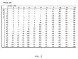
- FIG. 12shows these calculations computing the metrics M x .
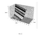
- FIG. 13shows a plot of the calculations shown in FIG. 12 .
- Digital mediahereafter referred to as media, comes in many forms, formats and containers, including Digital Video Disks, media files and media streams.
- the media contentscan be audio, video, images or meta data media components and various combinations of each.
- MP3is an audio-specific media format that was designed by the Moving Picture Experts Group (MPEG) as part of its MPEG-1 standard and later extended in the MPEG-2 standard.
- H264is a standard developed by the International Organization for Standardization (ISO)/International Electrotechnical Commission (IEC) joint working group, the Moving Picture Experts Group (MPEG).
- Moviesare typically multimedia formats with a video and multiple audio channels in it. For example a 5.1 movie contains 1 video channel (media component) and 6 audio channels (audio components). 5.1 is the common name for six channel surround sound multichannel audio systems.
- Digital media sourcesinclude media devices such as Digital Video Disk players, Blu-ray players, computer and mobile devices, and internet based “cloud” media services.
- Blu-ray Disc(BD) is an optical disc storage medium developed by the Blu-ray Disc Association.
- Internet based media servicesinclude services such as Netflix and SpotifyTM.
- Netflixis a media service and trademark of Netflix Inc.
- Spotifyis a media service and trademark of Spotify Ltd.
- Digital media playback (media rendering destinations) systemsinclude computer based devices, laptops and smartphones, as well as network audio and video devices.
- a SmartTVis an example of a digital media rendering device that can play media from an internet (cloud) based media service such as NetflixTM.
- a SmartTVwhich is also sometimes referred to as “Connected TV” or “Hybrid TV”, is used to describe the integration of the internet and Web features into modern television sets and set-top boxes, as well as the technological convergence between computers and these television sets/set-top boxes.
- An internet radio deviceis another example of a digital media rendering device.
- IPInternet Protocol
- An IP networked deviceis a device that adheres to the Internet Protocol suite standard.
- the Internet Protocol suiteis defined by the Internet Engineering Task Force [IETF] standards body.
- the Internetis a global system of interconnected computer networks that use the standard Internet Protocol (IP) suite.
- IP networkscome in many forms; the most prevalent being Ethernet based wired IP networking.
- Ethernetis a family of computer networking technologies for local area networks (LANs) that is standardized as IEEE (Institute of Electrical and Electronics Engineers) Standard 802.3.
- IEEEInstitute of Electrical and Electronics Engineers
- Wi-Fihas become the most popular means for connecting network devices wirelessly.
- Wi-Fiis a trademark of the Wi-Fi Alliance and a brand name for products using the IEEE 802.11 family of standards.
- a Wi-Fi networkis a type of IP network.
- IP networkingmeans that all of these media sources and playback systems, if not already network enabled, are becoming network enabled. Many Blu-ray players now have Ethernet and Wi-Fi network connectivity. Today most higher end TVs are smart TVs that have network capability. Similarly audio play back devices and even radios are network and internet enabled.
- Mobile devicessuch as mobile phones, tablets, readers, notebooks etc, are able to receive and store media and have powerful media (audio and video) capabilities and are connected to the internet via cell phone data services or broadband links, such as Wi-Fi that are high bandwidth and can access online media services that have wide and deep content.
- cell phone data services or broadband linkssuch as Wi-Fi that are high bandwidth and can access online media services that have wide and deep content.
- the applications targeted in this inventionare for a further extension of the above use cases where the media source connects to multiple destinations rather than a single destination.
- Theseare single point (one IP source) to multi point (multiple IP destinations) applications.
- An examplewould be where a user is playing a 5.1 movie media file to a wireless video playback device and 6 independent wireless audio destinations making up a full 5.1 surround sound system. In this case the media is going from one media source to 7 media destinations simultaneously.
- a useris playing music from one media source to 6 audio playback systems placed around the home in 6 different rooms.
- the video mediamay be rendered through one path, for example a specialized hardware path, and the audio may be rendered through a different network path.
- path delayspath latency
- network packet lossescan be high and it is necessary to mitigate these in order to deliver uninterrupted playback.
- the general structure of these applicationare that of multiple IP networked media source devices choosing, connecting and playing media to one or more IP networked media playback devices over an IP communication network.
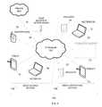
- FIG. 1shows an exemplary system 100 having multiple media source devices 104 and multiple media destination devices 106 .
- FIG. 2is a schematic diagram of such a media system 100 with one or more IP network-enabled media source devices 104 and one or more IP network enabled media destination devices 106 connected via an IP network 120 .
- a media source device 104can be any variety of computing devices that can originate digital media including computers (e.g. desktop, notebook 14 , tablet 12 , handheld), mobile devices (e.g. smart phone 10 , electronic book reader, organizer devices), as well as set-top boxes and game machines 16 .
- the mediais any form of digital media, including audio or video, images, data, and/or Meta data.
- Media destination devices 106are devices that can receive digital media over an IP network 120 and play this media. This includes IP-enabled audio and/or video and/or imaging devices that can render audio or video or images or combinations of these at the same time.
- Media destination devices 106include computers (e.g. desktop, notebook 15 , tablet 13 , handheld), mobile devices (e.g. smartphones, tablets, notebooks 15 ), network enabled TVs 20 , network enabled audio devices 18 , 22 .
- playing the mediameans rendering the audio such that a user can listen to the audio.
- the mediais video, playing means rendering the video such that a user can view the media.
- the mediaincludes both audio and video, it means rendering both the audio and the video.
- the mediais images, playing means displaying these images on a screen.
- media destination devices 106may also be referred to as media renderers or combinations of these terms.
- each media source 104can send its media to a selected set of media destination devices 106 for playback.
- the network 120 and all networks used and described in this invention to connect all devices, including the media sources 104 with the media destinations 106may be any network that supports an IP protocol. This includes any wired IP connectivity mechanism including Ethernet if wired and if wireless it includes any wireless IP connectivity mechanism including Wi-Fi. If this 120 is a Wi-Fi network, then the network 120 may include a Wi-Fi access point (AP) or Wi-Fi router 110 that manages the network in infrastructure mode. Alternatively, the network 120 may be using Wi-Fi Direct (Wi-Fi Direct is a standard of the Wi-Fi Alliance), in which case the AP 110 may not be present.
- the IP network 120may also be connected to the internet 800 through a wide area network connection 26 .
- the source 104may also have a remote device 114 associated with it such as a remote control device connected via an IP or other communication link 116 .
- a remote device 114associated with it such as a remote control device connected via an IP or other communication link 116 .
- the source 104 or network 120may have additional optional devices 112 such as a NAS (Network Attached Storage) device that provides media.
- NASNetwork Attached Storage
- IP networkscan use several different types of messaging including unicast, multicast and broadcast messaging. Messaging being the sending of IP packets.
- Unicast messagingis a type of Internet Protocol transmission in which information is sent from only one sender to only one receiver.
- Unicast transmissionis a one-to-one node transmission between two nodes only. In unicasting each outgoing packet has a unicast destination address, which means it is destined for a particular destination that has that address. All other destinations that may hear that packet ignore the packet, if the packet's destination address is not the same as that destination's address.
- Broadcastis a type of Internet Protocol transmission in which information is sent from just one computer, but is received by all the computers connected on the network. This would mean that every time a computer or a node transmits a ‘Broadcast’ packet, all the other computers can receive that information packet.
- Multicastis a type of Internet Protocol transmission or communication in which there may be more than one sender and the information sent is meant for a set of receivers that have joined a multicast group, the set of receivers possibly being a subset of all the receivers.
- each multicast packetis addressed to a multicast address. This address is a group address. Any destination can subscribe to the address and therefore can listen and receive packets sent to the multicast address that it subscribed to.
- the benefit of multicastingis that a single multicast packet sent can be received by multiple destinations. This saves network traffic if the same packet needs to be sent to multiple destinations. When the same data needs to be sent to multiple IP destinations generally, Broadcasting or Multicasting, rather than Unicasting, provides the most efficient use of the network.
- Broadcast and Multicastmay be used.
- Broadcast and Multicastwhen messages are sent, they are received by multiple destinations. Therefore in the present specification, the terms Broadcast and Multicast may be used interchangeably to refer to one packet being received by multiple destinations.
- this descriptiononly says the media is sent or transmitted without specifying whether it is broadcast, multicast or unicast. In this case, it means any one of these methods may be used for sending or transmitting the media.
- a Packetis a data set to be sent or received on an Internet Protocol network.
- the Packetmay or may not be the same as an ‘Internet Protocol Packet’.
- a Messagerefers to the logical information contained in such a packet.
- the term Segmentmay also be used to refer to a data set.
- a data setis a set of bytes of data. Data may be any type of data, including media or control or informational data.
- data and packetmay also be used interchangeable depending on context. Packet refers to a data set and data refers to data in general.
- POSIXis an acronym for “Portable Operating System Interface”, which is a family of standards specified by the IEEE for maintaining compatibility between operating systems.
- the mediais multicast to all the destinations and it is up to each destination to attempt to render the media appropriately. If during rendering there is an error where a renderer does not receive new media data or does not receive it correctly, the renderer may render erroneous data and then attempt to recover and continue correct media rendering from the point after the error when correct data is received. For example, during rendering of a H264 stream, if there is an incidental data drop out, the displayed image may pixilate briefly and then recover.
- the mediais transported over wireless, there is a very high likely hood of a media error, where the media is not received at each destination reliably or uniformly. If using broadcast or multicasts to send packets, the same broadcast or multi cast packet, may be received at one destination but not received/heard by another destination.
- this inventionuses a technique as described in U.S. patent application Ser. No. 11/627,957.
- IP networkswere first designed to operate over wired networks. By design, the packet communications on these networks were ‘best effort’. This means any packet transmitted on the network may not be received by the intended destination. This is most often due to a collision, where another device starts to communicate at the same moment as the device of interest, thereby causing a collision. Another method of loss would be the devices in the network path, such as routers, simply dropping the packet, for example due to the lack of buffer space. Other reasons for loss could be that the wired line is simply noisy and the packet transmission got corrupted, though this is rare for the wired case vs. the wireless case.
- Wi-FiIn Wi-Fi the differences in receipt of Wi-Fi traffic at each Wi-Fi device in a subnet is substantial. Therefore it is necessary to account for this in the applications described in this invention.
- this inventionproposes a mechanism, referred to as ‘Managed Receipt’ where the media broadcaster manages the receipt of media packets at each media receipt device.
- Broadcastrefers to the English meaning of the word as well as the IP communication methods of both broadcasting and multicasting. Broadcasting may also be implemented by unicasting IP packets to several destinations—which has the same effect as a broadcast, though it is not an efficient use of the network, if the entire payload in each packet is the same.
- TCPIn traditional point to point transmission protocols such as TCP, the internet standard Transmission Control Protocol as defined in Internet Protocol Request for Comment 793 (RFC 793 ), there is a need to have guaranteed packet transmission from end to end. TCP does so, by storing the packets to be sent in a buffer at the source, sending the packets to the destination and then discarding the packets at the source only when the destination end acknowledges receipt of the packet. If the destination does not acknowledge a packet, it is retransmitted.
- RRC 793Internet Protocol Request for Comment 793
- FIG. 3shows a typical TCP connection between a data source 104 and a data destination 106 .
- the source 104has an application 652 that uses TCP 658 for transporting media from the source 104 to the destination 106 .
- the destination 106has an application 670 that receives data from the TCP 658 layer.
- the TCP 658 layerconsists of a TCP source 656 , a TCP over IP network link 660 and a TCP destination 662 .
- the source application 652sends data via the TCP layer 658 by using a socket interface 654 .
- the destination application 670receives data via a socket interface 666 .
- TCPmanages the flow of data by providing receipt information at the TCP destination 662 to the TCP source 656 and the TCP source 656 using this information and a flow control algorithm to control the flow of data.
- FIG. 4shows a detailed view of the TCP source 656 , which contains a retransmission queue 300 and a sliding window 308 that maintains current transmission status information.
- FIG. 4shows the sliding window 308 algorithm used by TCP to control the flow of data from the TCP source 656 to the TCP destination 662 (See FIG. 3 ).
- a data setis sent from the source 656 (see FIG. 3 ) to the destination 662 (see FIG. 3 )
- the datais grouped into segments and each segment is marked with a sequence number that represents the byte number of the first byte of the segment.
- an outgoing segment 302is sent 660 from the source 656 to the destination 662 and then put 306 in a retransmission queue 300 at the TCP source 656 .
- the destination 662sends acknowledge messages back to the source 656 indicating the highest sequence number the destination 662 has received. Any segments in the retransmission queue 300 that have a sequence number that is equal to or less than the highest sequence number the destination 662 has received is discarded 314 by the source 656 from the retransmission queue 300 .
- the sliding window 308 in the retransmission queue 300therefore contains segments 312 - 316 that have been sent to the destination, but have not been acknowledged.
- the destinationincludes a sliding window 308 size 318 to use by the source. This sliding window 308 size 318 is used by the source 656 to limit the number of segments the source 656 can send that have not been acknowledged.
- the source 656For the earliest segment 312 that has not been acknowledged, the source 656 keeps track of a timeout value. If this value is greater than the Retransmission Time Out (RTO), then the source 656 restarts transmitting segments from this segment 312 .
- the RTO valueis computed based on a calculation using the round trip time.
- the RTOis dynamically computed and can change over time.
- TCPWhen TCP is sending data, it is sending to a single destination.
- any segment that is received over the network with a sequence number that is out of order and greater than the next sequence number the destination 662 is expectingis discarded by the destination 662 . This discarding of data received over the network, just because it was sent out of order, is very wasteful of network resources.
- out of order packetsare saved in the receive queue for use later.
- TCPIn TCP, after a segment times out, the TCP protocol restarts sending from the beginning of the retransmit window. This means any segments that have been received by the destination and have now been discarded are resent. This is again wasteful of network resources. In this invention retransmission of packets that have already been received is avoided.
- the destinationonly indicates the highest consecutive sequence number it has received. In this invention both the highest consecutive sequence number and any missing packets are reported by the destination.
- TCP philosophyis a slow start. This invention is tailored for a fast start and slows down fast when network conditions are bad.
- TCPassumes that packet losses are occurring due to congestion and therefore slows the throughput by reducing the amount of data in transit (reducing windows size 318 ) and waiting longer for acknowledges.
- packet lossmay occur unrelated to congestion. So when TCP is used over wireless and it decreases the rate, due to packet losses rather than congestion, this rate decrease is inappropriate and is an undesired effect.
- FIG. 5shows a timeline of packet (data set/segment) transmission and receipt at the source 400 and destination 402 using TCP.
- Thisshows an initial set of packets 1 through 6 being sent from the source 400 .
- an initial set of packets 404 marked 1, 2 and 3are received at the destination 402 .
- the next set of packets 410 , packets marked 4 and 5,are not received at the destination 402 until time 416 and therefore the acknowledge message for these packets 407 is not received by the source 400 till time 418 , which is well past the timeout period RTO 412 . Therefore the source 400 , when the timeout period RTO 412 expires, will retransmit packets 414 starting at the timed out packet marked 4 at time 420 .
- the second set of packets 414may arrive before time 416 or after time 416 .
- a key point regarding this algorithmis that the decision to retransmit packets is made by the source 400 based on a timeout period RTO 412 and the lack of an acknowledge message from the destination. Therefore the source 400 makes decisions based on limited information about receipt conditions at the destination 402 .
- TCPassumes those acknowledge delays or acknowledge absence is largely due to congestion rather than interference, it errs on the side of a long RTO and smaller window size and increases and decreases these respectively when timeouts occur.
- packetsare merely lost due to interference, such as in the case with Wi-Fi networks, rather than due to network congestion, this causes an inadvertent drop in transfer rate that is undesirable and unnecessary.
- packets marked 4 and 5 sent in set 410may arrive much later than a retransmission of these packets sent in set 414 .
- packets 4 and 5 in set 410may have been sent to an 802.11 access point from a source network adapter (uplink). The access point may then process other packets from other network adapters and may even lose RF connectivity with adapters.
- the access pointmay then reconnect and receive a new set 414 of packets 4 and 5 from the source network adapter and send them to the destination adapter (downlink), before finishing the downlink of packets 4 and 5 it received in set 410 , and that was waiting in a queue for processing, by sending them to the destination network adapter.
- FIG. 6Ashows a plot of the number of packets received at various packet to packet receive delays measured over a period of time.
- the packet to packet receive delayis the time interval between the receipt of a packet and the receipt of the next packet.
- the Y axis 554shows the number of packets received and the X axis 552 shows the delays.
- the plot 550shows that the packet to packet delays rise to a peak and then fall until they reach a point 564 where the delay goes to infinity, i.e. the packet is lost and will never arrive.
- a transmission algorithmwaits for a timeout period T O 560 for packets to arrive before requesting retransmission of these packets and if T O is set to be longer than the largest delay 564 seen, then the system will only retransmit packets that are truly lost. If the timeout period is set to a shorter interval such as T a 562 , then on many occasions the system will retransmit packets that are still on its way and may arrive later, after the timeout period T a has expired.
- FIG. 6Bshows the effect of this in more detail.
- Thisis a plot 568 of the total number of packets to arrive under a delay of T, as a percent of the total number of packets sent over the measurement period.
- the Y axis 566is the total packets received over the total packets sent as a percent and the X axis 567 is various possible timeout periods. If the timeout period is T O 560 and the corresponding delay is 506 , then the percent of packet retransmissions 508 will only be for lost packets. All other transmissions 504 will be for received packets.
- the timeout periodis set to T a 562 a shorter interval, and the corresponding delay is 559 , then the percent of packet retransmissions 558 will not only include lost packets 508 , but also a significant amount of packets 561 that are already on the way, but are just slow. This means that as the timeout period is shortened, the amount of excess repeats of packets already in transit increases. This retransmission of packets that have already been transmitted and will arrive in due course is wasteful of network resources. However, a short timeout period will ensure that packets that would otherwise be slow to arrive are received more promptly, by requesting their retransmission. Therefore the choice of the timeout period T is a tradeoff between requesting retransmission of delayed packets to ensure prompt packet receipt and wasting network resources in excessive retransmissions of the same packets.
- the destination 106may be rendering media sent from the media source 104 at a certain time offset from the time it was sent from the media source 104 . If the media takes longer than this time offset to get to the destination 106 , then the destination 106 will run out of media data to render and will underflow. Similarly, if the data sent to the destination 106 get lost along the way, then the destination will have no media to render, when it comes time to render the media that was lost and rendering will be erroneous. Therefore it is necessary to ensure that all media is received at the destination and if any retransmission needs to take place that it takes place and lost data is received before the destination rendering underflows.
- the time lost in retransmissionincludes the time it takes for a packet to be identified as lost at the destination, a loss notification being sent to the source, the source resending the packet and the retransmitted packet being received by the destination. This total time adds to the total system ‘latency’. If it takes 100 mSecs for this process to occur, data receipt at the destination will be delayed by 100 msecs.
- a major delay in the retransmission processis how long it takes to detect that a packet is lost.
- This inventiondescribes a process/algorithm known as a Loss Anticipation and Preemption algorithm (LAP) for keeping this loss detection delay low.
- LAPLoss Anticipation and Preemption algorithm
- FCPFireCast Control Protocol
- This LAP algorithmis designed to make early pre emptive decisions about potential packet loss and have these packets retransmitted. This, as mentioned above, is a tradeoff of using additional network resources to ensure the more timely availability of packet data.
- the destinationthat makes the decision to request a retransmission of data.
- the destinationhas more accurate and up to date information regarding the status of data received and is therefore in a better position to make timely requests for retransmission.
- FIG. 7shows what can happen in a typical Wi-Fi network.
- a Wi-Fi networkwill transmit the packets from Source 104 to destination 106 in the order that they were given to the source for transmission. However, in transmission, these packets may be lost, the order of packet transmissions mixed up and each packet may be delayed by an unknown amount of time. The occurrence of these is determined not only be RF/Wi-Fi factors as described above, but also due to implementation issues, such as buffer sizes in the access point and network traffic congestion at that particular moment.
- a set of packets 1 through 6are sent from the source 104 . Of these, packets 1 through 3 are received 420 after a transit time at the destination 106 . Packets 4 through 5 are delayed and arrive 422 at the destination 106 with a significant delay. Packet 6 however is not delayed and arrives 424 at the destination after a transit time.
- the source 104would wait a timeout period TT 430 for an acknowledge for the packets it sent and then would retransmit packets 4 through 7
- a metricis computed for the chance of a packet that has not been received as being lost. This metric is based on multiple factors; the order of receipt; delay in receipt and need for data expressed by an application using the media data. This metric is then used to request 426 retransmission of packets, as shown in FIG. 7 , and receive these packets 428 before the delayed packets 422 arrive.
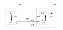
- FIG. 8shows the overall architecture used.
- the systemconsists of a media data source 104 and a media destination 106 .
- the media sourcehas a media application 624 that sends media to a media destination application 620 that is in the media destination 106 .
- the media applicationprovides the media to be transported to a transport layer 604 , named the FCP (FireCast Protocol) layer, via a transport layer interface 606 .
- the FCP transport protocolconsists of a FCP source 622 and a FCP destination 618 and an IP network link connecting them. This network link sends data packets 610 to the FCP destination 618 and status messages back 612 from the destination 618 to the FCP source 622 .
- the status messages 612include informational messages and request to retransmit packets.
- the destination application 620receives the media data via an application interface 616 to the FCP transport layer 604 .
- the destination application 620that is the consumer of the data provided by the FCP transport, in addition to receiving data through the application interface 616 also indicates to the FCP transport layer its current level of urgency or need for data to the Transport Layer 604 .
- the FCP destination 618is not a passive provider of information to the source.
- the FCP destination 618makes decisions regarding the data packets it has received and makes data packet retransmission requests 612 to the FCP source 622 .
- the FCP source 622services these requests. Data packet timeout decisions are made at the destination 618 .
- FIG. 9shows this system in more detail.
- the destination application 620is the consumer of media data packets 616 coming from the media source 624 (in FIG. 8 ) via the transport layer 604 .
- the media rendering media destination application 620has a buffer 635 to store the media data it has received via the transport interface 616 and has a media rendering component 630 that takes media data from the buffer and renders it 632 .
- the destination applications 620 using FCPalso provides information indicating its current Need level 642 to the FCP transport interface 614 .
- This Need levelindicates the destination/media data consumer applications need for data to the transport level 604 and is computed in a variety of ways. In this embodiment as the amount of media data available in the buffer 635 gets low, the Need for media data gets high. This Need value is computed by logic 634 that is monitoring the level 636 of valid media data in the buffer 635 .
- the FCP destination 618includes a received packet collection (RPC) 320 and LAP algorithm process 636 to provide receipt status and packet retransmission requests 612 to the FCP source 622 (see FIG. 8 ).
- the LAP algorithm 636periodically scans 644 the RPC 320 together with the need level 614 to make the retransmission requests 612 .
- PIDPacket Identifier
- Packetsare therefore identified by their PID and may be referred to as a PID in the description below. Since the destination 618 may receive these packets out of order, it has a reordering mechanism built into it. In this mechanism, the packets 648 are put INTO the received packet collection (RPC) 320 on receipt, in any order, as they are received. The packets are taken OUT 638 of the RPC 320 , based on PID order. I.e. packets are removed in incrementing PID order. If the next PID is not present in the RPC 320 , the destination's 618 packet removal process halts, waiting for this PID.
- RPCreceived packet collection
- the goal of the LAP algorithmis to ensure that the next PID required is already always present in the RPC 320 at the destination, when the destination application 620 wants to use/consume it by moving it to its buffer 635 .
- the contents of the RPC 320can be viewed as a linear list of Packets with ‘gaps’ 322 , 323 , 324 in the list for packets that have not yet been received.
- These packets 322 , 323 , 324 that have not been received yetare identified by their PIDs, and are referred to as missing PIDs 322 , 323 , 324 .
- FIG. 10shows details of the FCP destination 618 shown in FIG. 8 and FIG. 9 .
- the latest packet received 610 from the FCP source 622is 316 with PID 27 .
- the oldest and next packet that the destination application (see FIG. 8 ) 620 may consume via link 638is 309 PID 04 . It shows PID 16 , 322 , PID 20 323 and PID 21 324 as missing.
- a media In-Transit window 310identifies the part of the RPC 320 that has missing PIDs in it.
- the In-Transit windowsstarts 311 from the oldest missing PID location 322 , PID 16 in this diagram, and ends 302 at the most recent PID, 316 , PID 27 .
- the start 311 of the In-Transit windowwill move to PID 20 , 323 in this diagram, if PID 18 is received before PID 20 .
- the width of the In-Transit window 310which starts at the oldest missing PID 322 and ends at the most recent PID 316 , is Twd 325 .
- the amount of PIDs available Tavail 327 in the RPC 320includes the oldest packet received 309 to the packet 307 just before the oldest missing packet 322 . These PIDs are available to be used by the consumer application 620 .
- the LAP algorithmperiodically scans the RPC 320 and identifies PIDS in these ‘gaps’ as missing PIDs 322 , 323 , 324 .
- a missing PIDis a packet that has not been received, but has another packet received after it with a higher PID, than the missing PID.
- the LAPFor each such missing PID, the LAP also computes a metric based on how late the missing PID is with respect to the previous packet received.
- the LAPthen sends a list of missing packet PIDs to the FCP source 622 (see FIG. 8 ).
- the net effect of thisis that the destination 618 asks the FCP source 622 (see FIG. 8 ) to retransmit packets that are likely lost in the system, before the destination 106 (see FIG. 8 ) actually needs the packets.
- the cost of this methodis that the receiver may identify packets as missing that are actually still in transit and may be subsequently received. This amounts to some degree of duplicate transmissions.
- the LAPadjusts its missing PID identification scans and late packet metric to meet a balance between duplicate transmissions and minimal delays waiting for missing packets to be retransmitted.
- the missing PID identification scansare performed periodically at a 20 msec rate.
- a longer periodmay be used to reduce processor load for applications that do not require short latency.
- this scan periodcan be set as low as 5 msec to check for missing packets very frequently.
- the missing packetis the last packet in a sequence and has no following packet.
- the LAPwill trip a basic delay timeout and identify the packet as a late last packet based on this.
- FIG. 11shows the LAP algorithm used by the destination to request packet retransmissions in detail.
- the LAP processstarts 900 by 902 setting the working pointer to the packet at the start 311 (see FIG. 10 for some of the following references) of the In-Transit Window 310 and then checks this packet position 906 . If in checking for being the last packet 908 this is not the end of the In-Transit Window 302 and in checking for a missing packet in step 910 a packet is not present at this position 910 , this is a missing packet and it moves to calculate a D m value in step 914 .
- the D m valueis calculated using the delay since the previous most recent packet that was present and a current Need level 904 provided by the destination application 620 (see FIG.
- a missing packet metric M mis computed 916 and this metric is compared to a threshold 922 . If above the threshold 922 , a retransmit priority R m is calculated 926 and this missing PID is added 928 to a list of Late/Missing PIDs that will be requested for retransmission by the destination 618 . If M m in step 922 is below the threshold, the working pointer is moved to the next packet 930 and this packet position is checked 906 . If in step 910 the packet is present, no action is taken and the working pointer is moved to the next packet 930 and this packet position is checked 906 .
- a retransmit priority R lis calculated 924 and this late PID is added 934 to a list of Late/Missing PIDs that will be requested for retransmission by the destination 618 . In either case, since the working pointer is at the end of In-Transit window the LAP process ends 932 .
- FIG. 13shows a plot of these numbers. As can be seen as the Delay gets closer to 100% or the Need gets closer to 100%, the Metric reaches 100%.
- the FCP destination 618send a list of Late/Missing PIDs to the FCP source 622 , it includes for each Late/Missing PID the metric M m or M l and the retransmission priority R m or R l for that packet. The source can use this information to adjust how it processes and sends packets to each destination.
- Certain aspects of the present inventioninclude process steps and instructions described herein in the form of a method. It should be noted that the process steps and instructions of the present invention could be embodied in software, firmware or hardware, and when embodied in software, could be downloaded to reside on and be operated from different platforms used by real time network operating systems.
- the present inventionalso relates to an apparatus for performing the operations herein.
- This apparatusmay be specially constructed for the required purposes, or it may comprise a general-purpose computer selectively activated or reconfigured by a computer program stored on a computer readable medium that can be accessed by the computer.
- a computer programmay be stored in a tangible computer readable storage medium, such as, but is not limited to, any type of disk including floppy disks, optical disks, CD-ROMs, magnetic-optical disks, read-only memories (ROMs), random access memories (RAMs), EPROMs, EEPROMs, magnetic or optical cards, application specific integrated circuits (ASICs), or any type of media suitable for storing electronic instructions, and each coupled to a computer system bus.
- the computers referred to in the specificationmay include a single processor or may be architectures employing multiple processor designs for increased computing capability.
- the present inventionis well suited to a wide variety of computer network systems over numerous topologies.
- the configuration and management of large networkscomprise storage devices and computers that are communicatively coupled to dissimilar computers and storage devices over a network, such as the Internet, public networks, private networks, or other networks enabling communication between computing systems.
Landscapes
- Engineering & Computer Science (AREA)
- Multimedia (AREA)
- Signal Processing (AREA)
- Computer Networks & Wireless Communication (AREA)
- Computer Security & Cryptography (AREA)
- Environmental & Geological Engineering (AREA)
- Data Exchanges In Wide-Area Networks (AREA)
- Two-Way Televisions, Distribution Of Moving Picture Or The Like (AREA)
- Information Transfer Between Computers (AREA)
Abstract
Description
- Tlp: Time previous packet was received
- Tc: Current time
- dm: Delay of Missing packet=Tc−Tlp
- Dthm: Delay Threshold of Missing Packet
- Dminm: Delay Minimum for Missing Packet
- Dm: Delay as a percent of thresh hold
- Mm: Metric for Missing Packet as a percent
- N: Need as a percent
- Km: 1/16
- dl: Delay of Last packet=Tc−Tlp
- Kl: 1/16
- Dthl: Delay Threshold of Last Packet
- Dminl: Delay Minimum for Last Packet
- Dl: Delay as a percent of thresh hold
- Ml: Metric for Last packet as a percent
- MIN(A, B): returns the minimum of A or B
- Rm: Missing Packet retransmit priority
- Rl: Last Packet retransmit priority
- Dx: Dmor Dl
- Mx: Mmor Ml
- Rx: Rmor Rl
Dm=(dm−Dminm)/Dthm
Mm=Fn(N)*Fm(Dm)*Km
Fn(N)=2^(N/8)
Fm(Dm)=2^(Dm/8)
Mm=MIN((( 1/16)*2^((N/8)+(Dm/8))),100)
Rm=N
Dl=(dl−Dminl)/Dthm
Ml=Fn(N)*Fl(Dl)*Kl
Fl(Dl)=2^(Dl/8)
Ml=MIN((( 1/16)*2^((N/8)+(Dl/8))),100)
Rl=N
Claims (12)
Priority Applications (10)
| Application Number | Priority Date | Filing Date | Title |
|---|---|---|---|
| US13/561,029US8839065B2 (en) | 2011-07-29 | 2012-07-28 | Packet loss anticipation and pre emptive retransmission for low latency media applications |
| US14/303,502US9413799B2 (en) | 2007-01-27 | 2014-06-12 | Broadcasting media from a stationary source to multiple mobile devices over wi-fi |
| US14/303,527US9407670B2 (en) | 2007-01-27 | 2014-06-12 | Broadcasting media from a stationary source to multiple mobile devices over Wi-Fi |
| US14/487,031US9756127B2 (en) | 2011-07-29 | 2014-09-15 | Packet loss anticipation and preemptive retransmission for low latency media applications |
| US14/505,411US9338208B2 (en) | 2007-01-27 | 2014-10-02 | Common event-based multidevice media playback |
| US15/286,516US20170019198A1 (en) | 2006-01-28 | 2016-10-05 | System for synchronous playback of media using a hybrid bluetooth™ and wi-fi network |
| US15/285,489US9780894B2 (en) | 2006-01-28 | 2016-10-05 | Systems for synchronous playback of media using a hybrid bluetooth™ and Wi-Fi network |
| US15/381,092US9973290B2 (en) | 2006-01-28 | 2016-12-15 | System for media rebroadcasting for synchronized rendering across multiple devices |
| US15/389,438US20170136355A1 (en) | 2006-01-28 | 2016-12-22 | Synchronized multi-device mobile gaming |
| US15/618,541US20180007091A1 (en) | 2006-01-28 | 2017-06-09 | Synchronous media rendering over a spatially extended wireless network |
Applications Claiming Priority (2)
| Application Number | Priority Date | Filing Date | Title |
|---|---|---|---|
| US201161512924P | 2011-07-29 | 2011-07-29 | |
| US13/561,029US8839065B2 (en) | 2011-07-29 | 2012-07-28 | Packet loss anticipation and pre emptive retransmission for low latency media applications |
Related Parent Applications (3)
| Application Number | Title | Priority Date | Filing Date |
|---|---|---|---|
| US11/627,957Continuation-In-PartUS8677002B2 (en) | 2006-01-28 | 2007-01-27 | Streaming media system and method |
| US14/083,426Continuation-In-PartUS8762580B2 (en) | 2006-01-28 | 2013-11-18 | Common event-based multidevice media playback |
| US201615175026AContinuation-In-Part | 2006-01-28 | 2016-06-06 |
Related Child Applications (5)
| Application Number | Title | Priority Date | Filing Date |
|---|---|---|---|
| US14/083,426Continuation-In-PartUS8762580B2 (en) | 2006-01-28 | 2013-11-18 | Common event-based multidevice media playback |
| US14/303,502Continuation-In-PartUS9413799B2 (en) | 2006-01-28 | 2014-06-12 | Broadcasting media from a stationary source to multiple mobile devices over wi-fi |
| US14/303,527Continuation-In-PartUS9407670B2 (en) | 2006-01-28 | 2014-06-12 | Broadcasting media from a stationary source to multiple mobile devices over Wi-Fi |
| US14/487,031ContinuationUS9756127B2 (en) | 2011-07-29 | 2014-09-15 | Packet loss anticipation and preemptive retransmission for low latency media applications |
| US14/505,411Continuation-In-PartUS9338208B2 (en) | 2006-01-28 | 2014-10-02 | Common event-based multidevice media playback |
Publications (2)
| Publication Number | Publication Date |
|---|---|
| US20130028121A1 US20130028121A1 (en) | 2013-01-31 |
| US8839065B2true US8839065B2 (en) | 2014-09-16 |
Family
ID=47597150
Family Applications (6)
| Application Number | Title | Priority Date | Filing Date |
|---|---|---|---|
| US13/561,029Active2033-03-13US8839065B2 (en) | 2006-01-28 | 2012-07-28 | Packet loss anticipation and pre emptive retransmission for low latency media applications |
| US13/561,030Active2032-10-22US8837488B2 (en) | 2011-07-29 | 2012-07-28 | Two tier multiple sliding window mechanism for multidestination media applications |
| US13/561,031Expired - Fee RelatedUS9071418B2 (en) | 2011-07-29 | 2012-07-28 | Synchronous media rendering of demuxed media components across multiple devices |
| US14/487,031Active2033-09-22US9756127B2 (en) | 2011-07-29 | 2014-09-15 | Packet loss anticipation and preemptive retransmission for low latency media applications |
| US14/487,045ActiveUS9288263B2 (en) | 2011-07-29 | 2014-09-15 | Two tier multiple sliding window mechanism for multidestination media applications |
| US14/754,644ActiveUS9479584B2 (en) | 2011-07-29 | 2015-06-29 | Synchronous media rendering of demuxed media components across multiple devices |
Family Applications After (5)
| Application Number | Title | Priority Date | Filing Date |
|---|---|---|---|
| US13/561,030Active2032-10-22US8837488B2 (en) | 2011-07-29 | 2012-07-28 | Two tier multiple sliding window mechanism for multidestination media applications |
| US13/561,031Expired - Fee RelatedUS9071418B2 (en) | 2011-07-29 | 2012-07-28 | Synchronous media rendering of demuxed media components across multiple devices |
| US14/487,031Active2033-09-22US9756127B2 (en) | 2011-07-29 | 2014-09-15 | Packet loss anticipation and preemptive retransmission for low latency media applications |
| US14/487,045ActiveUS9288263B2 (en) | 2011-07-29 | 2014-09-15 | Two tier multiple sliding window mechanism for multidestination media applications |
| US14/754,644ActiveUS9479584B2 (en) | 2011-07-29 | 2015-06-29 | Synchronous media rendering of demuxed media components across multiple devices |
Country Status (1)
| Country | Link |
|---|---|
| US (6) | US8839065B2 (en) |
Cited By (7)
| Publication number | Priority date | Publication date | Assignee | Title |
|---|---|---|---|---|
| US20150006959A1 (en)* | 2011-07-29 | 2015-01-01 | Blackfire Research Corporation | Packet loss anticipation and preemptive retransmission for low latency media applications |
| US20150033091A1 (en)* | 2013-07-23 | 2015-01-29 | Electronics And Telecommunications Research Institute | Apparatus and method for requesting retransmission of lost packet based on mpeg media transport system |
| US20150244650A1 (en)* | 2014-02-21 | 2015-08-27 | Kyeong Ho Yang | Efficient packet processing at video receiver in multimedia communications over packet networks |
| WO2017034520A1 (en)* | 2015-08-21 | 2017-03-02 | Nokia Technologies Oy | Extent of out-of-sequence indication for multi-connectivity |
| US9763120B2 (en) | 2014-12-24 | 2017-09-12 | EVA Automation, Inc. | Redundant links for reliable communication |
| US10045221B2 (en)* | 2013-12-18 | 2018-08-07 | Qualcomm, Incorporated | TCP enhancement with limited licensed channel usage for wireless networks |
| US11612010B2 (en) | 2020-09-25 | 2023-03-21 | Zullikon Limited | System and method for ultra low latency wireless media streaming |
Families Citing this family (107)
| Publication number | Priority date | Publication date | Assignee | Title |
|---|---|---|---|---|
| KR20200090943A (en) | 2007-09-24 | 2020-07-29 | 애플 인크. | Embedded authentication systems in an electronic device |
| US8600120B2 (en) | 2008-01-03 | 2013-12-03 | Apple Inc. | Personal computing device control using face detection and recognition |
| US8638385B2 (en) | 2011-06-05 | 2014-01-28 | Apple Inc. | Device, method, and graphical user interface for accessing an application in a locked device |
| US8769624B2 (en) | 2011-09-29 | 2014-07-01 | Apple Inc. | Access control utilizing indirect authentication |
| US9002322B2 (en) | 2011-09-29 | 2015-04-07 | Apple Inc. | Authentication with secondary approver |
| US9654821B2 (en) | 2011-12-30 | 2017-05-16 | Sonos, Inc. | Systems and methods for networked music playback |
| US9521074B2 (en)* | 2012-05-10 | 2016-12-13 | Sonos, Inc. | Methods and apparatus for direct routing between nodes of networks |
| US20150208135A1 (en) | 2012-06-14 | 2015-07-23 | Flextronics Ap, Llc | Methods and displays for providing intelligent television badges |
| US10009445B2 (en)* | 2012-06-14 | 2018-06-26 | Qualcomm Incorporated | Avoiding unwanted TCP retransmissions using optimistic window adjustments |
| US9674587B2 (en) | 2012-06-26 | 2017-06-06 | Sonos, Inc. | Systems and methods for networked music playback including remote add to queue |
| US10404562B2 (en)* | 2012-10-22 | 2019-09-03 | Texas State University | Optimization of retransmission timeout boundary |
| US20140161061A1 (en)* | 2012-12-10 | 2014-06-12 | Xg Technology, Inc. | Hybrid arq system using a sliding purge window for wireless networks |
| US9544348B2 (en)* | 2013-01-04 | 2017-01-10 | Google Inc. | Cloud-based rendering |
| WO2014143776A2 (en) | 2013-03-15 | 2014-09-18 | Bodhi Technology Ventures Llc | Providing remote interactions with host device using a wireless device |
| US9501533B2 (en) | 2013-04-16 | 2016-11-22 | Sonos, Inc. | Private queue for a media playback system |
| US9247363B2 (en) | 2013-04-16 | 2016-01-26 | Sonos, Inc. | Playback queue transfer in a media playback system |
| US9361371B2 (en) | 2013-04-16 | 2016-06-07 | Sonos, Inc. | Playlist update in a media playback system |
| US10715973B2 (en) | 2013-05-29 | 2020-07-14 | Sonos, Inc. | Playback queue control transition |
| US9684484B2 (en) | 2013-05-29 | 2017-06-20 | Sonos, Inc. | Playback zone silent connect |
| US9953179B2 (en) | 2013-05-29 | 2018-04-24 | Sonos, Inc. | Private queue indicator |
| US9735978B2 (en) | 2013-05-29 | 2017-08-15 | Sonos, Inc. | Playback queue control via a playlist on a mobile device |
| US9495076B2 (en) | 2013-05-29 | 2016-11-15 | Sonos, Inc. | Playlist modification |
| US9703521B2 (en) | 2013-05-29 | 2017-07-11 | Sonos, Inc. | Moving a playback queue to a new zone |
| US9798510B2 (en)* | 2013-05-29 | 2017-10-24 | Sonos, Inc. | Connected state indicator |
| US10721171B2 (en) | 2013-06-24 | 2020-07-21 | Vecima Networks Inc. | Data transfer system and corresponding methods |
| US9898642B2 (en) | 2013-09-09 | 2018-02-20 | Apple Inc. | Device, method, and graphical user interface for manipulating user interfaces based on fingerprint sensor inputs |
| US10432529B2 (en) | 2013-09-19 | 2019-10-01 | Connectivity Systems Incorporated | Enhanced large data transmissions and catastrophic congestion avoidance over IPv6 TCP/IP networks |
| US9350663B2 (en) | 2013-09-19 | 2016-05-24 | Connectivity Systems Incorporated | Enhanced large data transmissions and catastrophic congestion avoidance over TCP/IP networks |
| US10296884B2 (en) | 2013-09-30 | 2019-05-21 | Sonos, Inc. | Personalized media playback at a discovered point-of-sale display |
| US10270705B1 (en)* | 2013-12-18 | 2019-04-23 | Violin Systems Llc | Transmission of stateful data over a stateless communications channel |
| US10043185B2 (en) | 2014-05-29 | 2018-08-07 | Apple Inc. | User interface for payments |
| US9967401B2 (en) | 2014-05-30 | 2018-05-08 | Apple Inc. | User interface for phone call routing among devices |
| EP3108342B1 (en) | 2014-05-30 | 2019-10-23 | Apple Inc. | Transition from use of one device to another |
| US10009413B2 (en)* | 2014-06-26 | 2018-06-26 | At&T Intellectual Property I, L.P. | Collaborative media playback |
| CN105594219B (en)* | 2014-07-31 | 2019-08-20 | Lg 电子株式会社 | Transmitting/reception processing device and method for broadcast singal |
| US10339293B2 (en) | 2014-08-15 | 2019-07-02 | Apple Inc. | Authenticated device used to unlock another device |
| US20160080826A1 (en)* | 2014-09-16 | 2016-03-17 | Qualcomm Incorporated | Systems, methods and apparatus for broadcasting pay-per-view video over enhanced multimedia broadcast multicast service |
| US9496987B2 (en) | 2014-12-11 | 2016-11-15 | International Business Machines Corporation | Method for redelivering a subset of messages in a packet to a receiver application |
| WO2016134186A1 (en)* | 2015-02-18 | 2016-08-25 | Blackfire Research Corporation | Synchronous media rendering over wireless networks with wireless performance monitoring |
| CN105245619A (en)* | 2015-10-27 | 2016-01-13 | 广东欧珀移动通信有限公司 | Data synchronization method and device for smart devices |
| US10749969B2 (en)* | 2015-12-29 | 2020-08-18 | Oath Inc. | Content presentation using a device set |
| DK179186B1 (en)* | 2016-05-19 | 2018-01-15 | Apple Inc | REMOTE AUTHORIZATION TO CONTINUE WITH AN ACTION |
| CN114693289A (en) | 2016-06-11 | 2022-07-01 | 苹果公司 | User interface for trading |
| US10621581B2 (en) | 2016-06-11 | 2020-04-14 | Apple Inc. | User interface for transactions |
| DK201670622A1 (en) | 2016-06-12 | 2018-02-12 | Apple Inc | User interfaces for transactions |
| US9842330B1 (en) | 2016-09-06 | 2017-12-12 | Apple Inc. | User interfaces for stored-value accounts |
| DK179978B1 (en) | 2016-09-23 | 2019-11-27 | Apple Inc. | Image data for enhanced user interactions |
| US10496808B2 (en) | 2016-10-25 | 2019-12-03 | Apple Inc. | User interface for managing access to credentials for use in an operation |
| CN107193887B (en)* | 2017-04-28 | 2019-01-29 | 武汉斗鱼网络科技有限公司 | A kind of method and device for the resource that Loads Image |
| US11431836B2 (en) | 2017-05-02 | 2022-08-30 | Apple Inc. | Methods and interfaces for initiating media playback |
| US10992795B2 (en) | 2017-05-16 | 2021-04-27 | Apple Inc. | Methods and interfaces for home media control |
| US20220279063A1 (en) | 2017-05-16 | 2022-09-01 | Apple Inc. | Methods and interfaces for home media control |
| CN111343060B (en) | 2017-05-16 | 2022-02-11 | 苹果公司 | Method and interface for home media control |
| WO2019003955A1 (en)* | 2017-06-29 | 2019-01-03 | ソニー株式会社 | Communication system and control device |
| KR102185854B1 (en) | 2017-09-09 | 2020-12-02 | 애플 인크. | Implementation of biometric authentication |
| CN117077102A (en) | 2017-09-09 | 2023-11-17 | 苹果公司 | Implementation of biometric authentication |
| CN108012177A (en)* | 2017-12-01 | 2018-05-08 | 晨星半导体股份有限公司 | Audio and video playing system and audio data playing method applied to same |
| US11032257B1 (en) | 2017-12-08 | 2021-06-08 | Rankin Labs, Llc | Method for covertly delivering a packet of data over a network |
| US11861025B1 (en) | 2018-01-08 | 2024-01-02 | Rankin Labs, Llc | System and method for receiving and processing a signal within a TCP/IP protocol stack |
| US10725743B2 (en) | 2018-01-22 | 2020-07-28 | John Rankin | System and method for generating random numbers |
| US10574439B2 (en) | 2018-01-31 | 2020-02-25 | John Rankin | System and method for secure communication using random blocks or random numbers |
| US11876847B2 (en)* | 2018-02-05 | 2024-01-16 | D&M Holding | System and method for synchronizing networked rendering devices |
| WO2019168978A1 (en) | 2018-02-28 | 2019-09-06 | John Rankin | System and method for expanding a set of random values |
| US11289070B2 (en) | 2018-03-23 | 2022-03-29 | Rankin Labs, Llc | System and method for identifying a speaker's community of origin from a sound sample |
| US11170085B2 (en) | 2018-06-03 | 2021-11-09 | Apple Inc. | Implementation of biometric authentication |
| US11341985B2 (en) | 2018-07-10 | 2022-05-24 | Rankin Labs, Llc | System and method for indexing sound fragments containing speech |
| WO2020033540A1 (en) | 2018-08-10 | 2020-02-13 | John Rankin | System and method for covertly transmitting a payload of data |
| US11689543B2 (en) | 2018-08-10 | 2023-06-27 | Rankin Labs, Llc | System and method for detecting transmission of a covert payload of data |
| WO2020041390A1 (en) | 2018-08-21 | 2020-02-27 | John Rankin | System and method for scattering network traffic across a number of disparate hosts |
| US11100349B2 (en) | 2018-09-28 | 2021-08-24 | Apple Inc. | Audio assisted enrollment |
| US10860096B2 (en) | 2018-09-28 | 2020-12-08 | Apple Inc. | Device control using gaze information |
| US10903977B2 (en) | 2018-12-19 | 2021-01-26 | Rankin Labs, Llc | Hidden electronic file systems |
| US11989320B2 (en) | 2018-12-19 | 2024-05-21 | Rankin Labs, Llc | Hidden electronic file system within non-hidden electronic file system |
| US11108671B2 (en) | 2019-01-21 | 2021-08-31 | Rankin Labs, Llc | Systems and methods for processing network traffic using dynamic memory |
| US11526357B2 (en) | 2019-01-21 | 2022-12-13 | Rankin Labs, Llc | Systems and methods for controlling machine operations within a multi-dimensional memory space |
| WO2020154219A1 (en) | 2019-01-21 | 2020-07-30 | John Rankin | Systems and methods for controlling machine operations |
| US10944697B2 (en) | 2019-03-26 | 2021-03-09 | Microsoft Technology Licensing, Llc | Sliding window buffer for minimum local resource requirements |
| WO2020214752A1 (en) | 2019-04-17 | 2020-10-22 | John Rankin | System and method for detecting hidden chemicals within objects in a non-invasive manner |
| WO2020214757A1 (en) | 2019-04-17 | 2020-10-22 | John Rankin | Virtual memory pool within a network which is accessible from multiple platforms |
| JP7226084B2 (en)* | 2019-05-16 | 2023-02-21 | オムロン株式会社 | Information processing equipment |
| US11729184B2 (en) | 2019-05-28 | 2023-08-15 | Rankin Labs, Llc | Detecting covertly stored payloads of data within a network |
| WO2020243249A1 (en) | 2019-05-28 | 2020-12-03 | John Rankin | Covertly storing a payload of data within a network |
| US11372773B2 (en) | 2019-05-28 | 2022-06-28 | Rankin Labs, Llc | Supporting a virtual memory area at a remote computing machine |
| CN115562613A (en) | 2019-05-31 | 2023-01-03 | 苹果公司 | User interface for audio media controls |
| US10996917B2 (en) | 2019-05-31 | 2021-05-04 | Apple Inc. | User interfaces for audio media control |
| US11105934B2 (en) | 2019-08-07 | 2021-08-31 | Rankin Labs, Llc | Determining proximity and attraction of objects within a coordinate system |
| WO2021025728A1 (en) | 2019-08-07 | 2021-02-11 | John Rankin | System and method for indirect advertising |
| US11394480B2 (en)* | 2019-08-23 | 2022-07-19 | Bose Corporation | Systems and methods for synchronizing device clocks |
| CN110855584B (en)* | 2019-10-16 | 2022-02-01 | 武汉绿色网络信息服务有限责任公司 | Method and device for TCP out-of-order recombination |
| US11699037B2 (en) | 2020-03-09 | 2023-07-11 | Rankin Labs, Llc | Systems and methods for morpheme reflective engagement response for revision and transmission of a recording to a target individual |
| EP3902206B1 (en)* | 2020-04-21 | 2022-02-16 | TTTech Computertechnik Aktiengesellschaft | Fault tolerant distribution unit and method for providing fault tolerant global time |
| US11816194B2 (en) | 2020-06-21 | 2023-11-14 | Apple Inc. | User interfaces for managing secure operations |
| US11392291B2 (en) | 2020-09-25 | 2022-07-19 | Apple Inc. | Methods and interfaces for media control with dynamic feedback |
| EP4252409A2 (en)* | 2020-11-29 | 2023-10-04 | Appario Global Solutions (AGS) AG | Method and system for capturing images |
| CR20230298A (en)* | 2020-12-01 | 2023-10-23 | Arris Entpr Llc | Partial video async support using r-macphy device |
| EP4264460A1 (en) | 2021-01-25 | 2023-10-25 | Apple Inc. | Implementation of biometric authentication |
| JP2024505547A (en)* | 2021-02-01 | 2024-02-06 | アリス エンタープライジズ リミティド ライアビリティ カンパニー | Adaptive video slew rate for video delivery |
| US12210603B2 (en) | 2021-03-04 | 2025-01-28 | Apple Inc. | User interface for enrolling a biometric feature |
| US11962400B2 (en)* | 2021-05-03 | 2024-04-16 | Arris Enterprises Llc | System for channel map delivery for hi split cable networks |
| US12216754B2 (en) | 2021-05-10 | 2025-02-04 | Apple Inc. | User interfaces for authenticating to perform secure operations |
| US11847378B2 (en) | 2021-06-06 | 2023-12-19 | Apple Inc. | User interfaces for audio routing |
| CN119376677A (en) | 2021-06-06 | 2025-01-28 | 苹果公司 | User interface for audio routing |
| US11784956B2 (en) | 2021-09-20 | 2023-10-10 | Apple Inc. | Requests to add assets to an asset account |
| US12255942B2 (en)* | 2021-10-08 | 2025-03-18 | Nagravision Sarl | Method and system for generating media content |
| US11743193B2 (en) | 2021-11-01 | 2023-08-29 | Seagate Technology Llc | Sliding window protocol for communication among more than two participants |
| US11700402B1 (en)* | 2022-03-25 | 2023-07-11 | Nvidia Corporation | Dynamically reducing stutter and latency in video streaming applications |
| CN117897974A (en)* | 2022-05-24 | 2024-04-16 | 吉欧平台有限公司 | System and method for offloading a selected number of users |
Citations (12)
| Publication number | Priority date | Publication date | Assignee | Title |
|---|---|---|---|---|
| US20010007137A1 (en)* | 1999-12-31 | 2001-07-05 | Nokia Mobile Phones Ltd. | Method for making data transmission more effective and a data transmission protocol |
| US6907460B2 (en)* | 2001-01-18 | 2005-06-14 | Koninklijke Philips Electronics N.V. | Method for efficient retransmission timeout estimation in NACK-based protocols |
| US20050180327A1 (en)* | 2004-02-12 | 2005-08-18 | International Business Machines Corporation | Method and apparatus for handling reordered data packets |
| US7035214B1 (en)* | 1999-09-28 | 2006-04-25 | Nortel Networks Limited | System and method for a negative acknowledgement-based transmission control protocol |
| US7298701B2 (en)* | 2002-10-31 | 2007-11-20 | Nokia Corporation | Apparatus, and associated method, for requesting data retransmission in a packet radio communication system |
| US20080037420A1 (en)* | 2003-10-08 | 2008-02-14 | Bob Tang | Immediate ready implementation of virtually congestion free guaranteed service capable network: external internet nextgentcp (square waveform) TCP friendly san |
| US20090019505A1 (en)* | 2007-06-29 | 2009-01-15 | Toshiba America Research, Inc. | Streaming video over multiple network interfaces |
| US7607062B2 (en)* | 2002-03-25 | 2009-10-20 | Akamai Technologies, Inc. | System for fast recovery from losses for reliable data communication protocols |
| US20090279482A1 (en)* | 2008-05-09 | 2009-11-12 | Qualcomm Incorporated | Techniques for enhanced backhaul flow control |
| US7848287B2 (en)* | 2006-05-16 | 2010-12-07 | Telefonaktiebolaget Lm Ericsson | Bi-directional RLC non-persistent mode for low delay services |
| US20110035641A1 (en)* | 1999-04-20 | 2011-02-10 | At&T Intellectual Property I, L.P. | Proxy Apparatus and Method for Streaming Media Information and for Increasing the Quality of Stored Media Information |
| US20140050095A1 (en)* | 2011-03-21 | 2014-02-20 | Nokia Siemens Networks Oy | Method and Apparatus to Improve TCP Performance in Mobile Networks |
Family Cites Families (24)
| Publication number | Priority date | Publication date | Assignee | Title |
|---|---|---|---|---|
| US7577782B2 (en)* | 1996-02-02 | 2009-08-18 | Sony Corporation | Application programming interface for data transfer and bus management over a bus structure |
| US6765904B1 (en)* | 1999-08-10 | 2004-07-20 | Texas Instruments Incorporated | Packet networks |
| KR20030003063A (en)* | 2001-06-29 | 2003-01-09 | 마츠시타 덴끼 산교 가부시키가이샤 | Data reproduction apparatus and method the same |
| US8253750B1 (en)* | 2004-02-14 | 2012-08-28 | Nvidia Corporation | Digital media processor |
| US7869428B2 (en)* | 2004-07-14 | 2011-01-11 | Nippon Telegraph And Telephone Corporation | Packet transmission method and packet transmission device |
| US8086575B2 (en)* | 2004-09-23 | 2011-12-27 | Rovi Solutions Corporation | Methods and apparatus for integrating disparate media formats in a networked media system |
| EP1820309B1 (en)* | 2004-12-03 | 2008-08-27 | Koninklijke Philips Electronics N.V. | Streaming memory controller |
| US8677002B2 (en)* | 2006-01-28 | 2014-03-18 | Blackfire Research Corp | Streaming media system and method |
| US8839065B2 (en)* | 2011-07-29 | 2014-09-16 | Blackfire Research Corporation | Packet loss anticipation and pre emptive retransmission for low latency media applications |
| EP2036350B1 (en)* | 2006-06-19 | 2015-07-22 | Telefonaktiebolaget LM Ericsson (publ) | Media channel management |
| US7958246B2 (en)* | 2007-08-09 | 2011-06-07 | Kount Inc. | Establishing unique sessions for DNS subscribers |
| EP2186218A4 (en)* | 2007-08-21 | 2012-07-11 | Packetvideo Corp | Mobile media router and method for using same |
| US8219711B2 (en)* | 2008-11-24 | 2012-07-10 | Juniper Networks, Inc. | Dynamic variable rate media delivery system |
| US8321564B2 (en)* | 2008-12-24 | 2012-11-27 | Broadcom Corporation | Rendering device selection in a home network |
| CA2669193C (en)* | 2009-06-16 | 2014-09-30 | Ruggedcom Inc. | Discovery and rediscovery protocol method and system |
| US8184540B1 (en)* | 2009-12-11 | 2012-05-22 | Juniper Networks, Inc. | Packet lifetime-based memory allocation |
| EP2661863B1 (en)* | 2011-01-04 | 2016-07-20 | Thomson Licensing | Apparatus and method for transmitting live media content |
| US20120173383A1 (en)* | 2011-01-05 | 2012-07-05 | Thomson Licensing | Method for implementing buddy-lock for obtaining media assets that are consumed or recommended |
| EP2700244B1 (en)* | 2011-04-21 | 2016-06-22 | Shah Talukder | Flow-control based switched group video chat and real-time interactive broadcast |
| US9141616B2 (en)* | 2011-05-06 | 2015-09-22 | Google Inc. | Physical confirmation for network-provided content |
| US20120317492A1 (en)* | 2011-05-27 | 2012-12-13 | Telefon Projekt LLC | Providing Interactive and Personalized Multimedia Content from Remote Servers |
| US9438883B2 (en)* | 2012-04-09 | 2016-09-06 | Intel Corporation | Quality of experience reporting for combined unicast-multicast/broadcast streaming of media content |
| US8948839B1 (en)* | 2013-08-06 | 2015-02-03 | L.I.F.E. Corporation S.A. | Compression garments having stretchable and conductive ink |
| US20140335816A1 (en)* | 2013-05-13 | 2014-11-13 | Jesse Wayne Long | Key fob communicator |
- 2012
- 2012-07-28USUS13/561,029patent/US8839065B2/enactiveActive
- 2012-07-28USUS13/561,030patent/US8837488B2/enactiveActive
- 2012-07-28USUS13/561,031patent/US9071418B2/ennot_activeExpired - Fee Related
- 2014
- 2014-09-15USUS14/487,031patent/US9756127B2/enactiveActive
- 2014-09-15USUS14/487,045patent/US9288263B2/enactiveActive
- 2015
- 2015-06-29USUS14/754,644patent/US9479584B2/enactiveActive
Patent Citations (12)
| Publication number | Priority date | Publication date | Assignee | Title |
|---|---|---|---|---|
| US20110035641A1 (en)* | 1999-04-20 | 2011-02-10 | At&T Intellectual Property I, L.P. | Proxy Apparatus and Method for Streaming Media Information and for Increasing the Quality of Stored Media Information |
| US7035214B1 (en)* | 1999-09-28 | 2006-04-25 | Nortel Networks Limited | System and method for a negative acknowledgement-based transmission control protocol |
| US20010007137A1 (en)* | 1999-12-31 | 2001-07-05 | Nokia Mobile Phones Ltd. | Method for making data transmission more effective and a data transmission protocol |
| US6907460B2 (en)* | 2001-01-18 | 2005-06-14 | Koninklijke Philips Electronics N.V. | Method for efficient retransmission timeout estimation in NACK-based protocols |
| US7607062B2 (en)* | 2002-03-25 | 2009-10-20 | Akamai Technologies, Inc. | System for fast recovery from losses for reliable data communication protocols |
| US7298701B2 (en)* | 2002-10-31 | 2007-11-20 | Nokia Corporation | Apparatus, and associated method, for requesting data retransmission in a packet radio communication system |
| US20080037420A1 (en)* | 2003-10-08 | 2008-02-14 | Bob Tang | Immediate ready implementation of virtually congestion free guaranteed service capable network: external internet nextgentcp (square waveform) TCP friendly san |
| US20050180327A1 (en)* | 2004-02-12 | 2005-08-18 | International Business Machines Corporation | Method and apparatus for handling reordered data packets |
| US7848287B2 (en)* | 2006-05-16 | 2010-12-07 | Telefonaktiebolaget Lm Ericsson | Bi-directional RLC non-persistent mode for low delay services |
| US20090019505A1 (en)* | 2007-06-29 | 2009-01-15 | Toshiba America Research, Inc. | Streaming video over multiple network interfaces |
| US20090279482A1 (en)* | 2008-05-09 | 2009-11-12 | Qualcomm Incorporated | Techniques for enhanced backhaul flow control |
| US20140050095A1 (en)* | 2011-03-21 | 2014-02-20 | Nokia Siemens Networks Oy | Method and Apparatus to Improve TCP Performance in Mobile Networks |
Cited By (15)
| Publication number | Priority date | Publication date | Assignee | Title |
|---|---|---|---|---|
| US20150006959A1 (en)* | 2011-07-29 | 2015-01-01 | Blackfire Research Corporation | Packet loss anticipation and preemptive retransmission for low latency media applications |
| US9756127B2 (en)* | 2011-07-29 | 2017-09-05 | Blackfire Research Corporation | Packet loss anticipation and preemptive retransmission for low latency media applications |
| US20150033091A1 (en)* | 2013-07-23 | 2015-01-29 | Electronics And Telecommunications Research Institute | Apparatus and method for requesting retransmission of lost packet based on mpeg media transport system |
| US10045221B2 (en)* | 2013-12-18 | 2018-08-07 | Qualcomm, Incorporated | TCP enhancement with limited licensed channel usage for wireless networks |
| US20150244650A1 (en)* | 2014-02-21 | 2015-08-27 | Kyeong Ho Yang | Efficient packet processing at video receiver in multimedia communications over packet networks |
| US9628411B2 (en)* | 2014-02-21 | 2017-04-18 | Dialogic Corporation | Efficient packet processing at video receiver in multimedia communications over packet networks |
| US10098023B2 (en) | 2014-12-24 | 2018-10-09 | EVA Automation, Inc. | Redundant links for reliable communication |
| US9894541B2 (en) | 2014-12-24 | 2018-02-13 | EVA Automation, Inc. | Redundant links for reliable communication |
| US9763120B2 (en) | 2014-12-24 | 2017-09-12 | EVA Automation, Inc. | Redundant links for reliable communication |
| US10117119B2 (en) | 2014-12-24 | 2018-10-30 | EVA Automation, Inc. | Redundant links for reliable communication |
| US10200892B2 (en) | 2014-12-24 | 2019-02-05 | EVA Automation, Inc. | Redundant links for reliable communication |
| US11297516B2 (en) | 2014-12-24 | 2022-04-05 | B&W Group Ltd. | Redundant links for reliable communication |
| US11729644B2 (en) | 2014-12-24 | 2023-08-15 | B&W Group Ltd. | Redundant links for reliable communication |
| WO2017034520A1 (en)* | 2015-08-21 | 2017-03-02 | Nokia Technologies Oy | Extent of out-of-sequence indication for multi-connectivity |
| US11612010B2 (en) | 2020-09-25 | 2023-03-21 | Zullikon Limited | System and method for ultra low latency wireless media streaming |
Also Published As
| Publication number | Publication date |
|---|---|
| US9756127B2 (en) | 2017-09-05 |
| US8837488B2 (en) | 2014-09-16 |
| US9071418B2 (en) | 2015-06-30 |
| US20130028263A1 (en) | 2013-01-31 |
| US20130031217A1 (en) | 2013-01-31 |
| US20150304418A1 (en) | 2015-10-22 |
| US9479584B2 (en) | 2016-10-25 |
| US20150071293A1 (en) | 2015-03-12 |
| US20130028121A1 (en) | 2013-01-31 |
| US9288263B2 (en) | 2016-03-15 |
| US20150006959A1 (en) | 2015-01-01 |
Similar Documents
| Publication | Publication Date | Title |
|---|---|---|
| US9756127B2 (en) | Packet loss anticipation and preemptive retransmission for low latency media applications | |
| US11381622B2 (en) | Method and apparatus for media data delivery control | |
| US9565007B2 (en) | Method of receiving a point-to-multipoint service in a wireless communication system | |
| EP1977537B1 (en) | Media data transfer in a network environment | |
| US20070286121A1 (en) | Systems and techniques for selective point-to-multipoint retransmission of multicast frames in a wireless network | |
| EP2214349A1 (en) | Relay device and method, and program | |
| KR20160098310A (en) | Session management and control procedures for supporting multiple groups of sink devices in a peer-to-peer wireless display system | |
| MXPA04005467A (en) | METHOD AND SYSTEM TO REINTENT THE FILLING OF HOLES, WITH THE BEST EFFORT, AWARE OF THE TIME FOR NETWORK COMMUNICATIONS. | |
| CN113347578B (en) | Audio data transmission method, device and system, storage medium and earphone | |
| US11196631B2 (en) | Multi-unicast discovery of devices on a network | |
| TW201306527A (en) | Method for transmitting a packet via heterogeneous networks | |
| US20160234031A1 (en) | Centralized Application Level Multicasting with Peer-Assisted Application Level Feedback for Scalable Multimedia Data Distribution in WiFi Miracast | |
| US20160234032A1 (en) | Unified Service Discovery with Peer-Assisted Resource Management for Service Mediation and Addressing Control in WiFi-Miracast | |
| CA2974228C (en) | Delay compensation for broadcast adaptive bitrate streaming | |
| US10375134B2 (en) | Method and device for low latency group-addressed streaming | |
| US8127196B2 (en) | Server and client for determining error restoration according to image data transmission, and method of determining error restoration according to image data transmission | |
| US9729903B2 (en) | Data transmitting device and method | |
| CN104025523A (en) | Apparatus And Method For Transmitting A Message To Multiple Receivers | |
| US20170019353A1 (en) | Two tier multiple sliding window mechanism for multidestination media applications | |
| US8837344B2 (en) | Apparatus and method for multicast/broadcast service data transmission synchronization | |
| JP2017092581A (en) | Gateway device, broadcast receiving device, broadcast relay method, broadcast reception method, broadcast relay program, and broadcast reception program | |
| WO2025073206A1 (en) | Video stream live broadcast method, streaming media server, and readable storage medium |
Legal Events
| Date | Code | Title | Description |
|---|---|---|---|
| AS | Assignment | Owner name:BLACKFIRE RESEARCH CORPORATION, CALIFORNIA Free format text:ASSIGNMENT OF ASSIGNORS INTEREST;ASSIGNOR:RAJAPAKSE, RAVI;REEL/FRAME:031187/0815 Effective date:20130910 | |
| STCF | Information on status: patent grant | Free format text:PATENTED CASE | |
| FEPP | Fee payment procedure | Free format text:MAINTENANCE FEE REMINDER MAILED (ORIGINAL EVENT CODE: REM.) | |
| FEPP | Fee payment procedure | Free format text:SURCHARGE FOR LATE PAYMENT, SMALL ENTITY (ORIGINAL EVENT CODE: M2554); ENTITY STATUS OF PATENT OWNER: SMALL ENTITY | |
| MAFP | Maintenance fee payment | Free format text:PAYMENT OF MAINTENANCE FEE, 4TH YR, SMALL ENTITY (ORIGINAL EVENT CODE: M2551); ENTITY STATUS OF PATENT OWNER: SMALL ENTITY Year of fee payment:4 | |
| AS | Assignment | Owner name:ROKU, INC., CALIFORNIA Free format text:ASSIGNMENT OF ASSIGNORS INTEREST;ASSIGNOR:BLACKFIRE RESEARCH CORPORATION;REEL/FRAME:055695/0161 Effective date:20210312 | |
| FEPP | Fee payment procedure | Free format text:ENTITY STATUS SET TO UNDISCOUNTED (ORIGINAL EVENT CODE: BIG.); ENTITY STATUS OF PATENT OWNER: LARGE ENTITY | |
| MAFP | Maintenance fee payment | Free format text:PAYMENT OF MAINTENANCE FEE, 8TH YEAR, LARGE ENTITY (ORIGINAL EVENT CODE: M1552); ENTITY STATUS OF PATENT OWNER: LARGE ENTITY Year of fee payment:8 | |
| AS | Assignment | Owner name:CITIBANK, N.A., TEXAS Free format text:SECURITY INTEREST;ASSIGNOR:ROKU, INC.;REEL/FRAME:068982/0377 Effective date:20240916 |