US8837889B2 - Single mode optical fiber - Google Patents
Single mode optical fiberDownload PDFInfo
- Publication number
- US8837889B2 US8837889B2US13/197,042US201113197042AUS8837889B2US 8837889 B2US8837889 B2US 8837889B2US 201113197042 AUS201113197042 AUS 201113197042AUS 8837889 B2US8837889 B2US 8837889B2
- Authority
- US
- United States
- Prior art keywords
- optical transmission
- transmission fiber
- cladding
- inner cladding
- wavelength
- Prior art date
- Legal status (The legal status is an assumption and is not a legal conclusion. Google has not performed a legal analysis and makes no representation as to the accuracy of the status listed.)
- Active, expires
Links
- 239000013307optical fiberSubstances0.000titledescription13
- 239000000835fiberSubstances0.000claimsabstractdescription192
- 238000005253claddingMethods0.000claimsabstractdescription131
- 230000003287optical effectEffects0.000claimsabstractdescription93
- 230000005540biological transmissionEffects0.000claimsabstractdescription83
- 238000005452bendingMethods0.000claimsabstractdescription62
- 229910052732germaniumInorganic materials0.000claimsabstractdescription28
- GNPVGFCGXDBREM-UHFFFAOYSA-Ngermanium atomChemical compound[Ge]GNPVGFCGXDBREM-UHFFFAOYSA-N0.000claimsabstractdescription27
- 239000006185dispersionSubstances0.000claimsdescription21
- 238000004804windingMethods0.000claimsdescription9
- 238000003860storageMethods0.000claimsdescription6
- 230000001747exhibiting effectEffects0.000abstract1
- VYPSYNLAJGMNEJ-UHFFFAOYSA-NSilicium dioxideChemical groupO=[Si]=OVYPSYNLAJGMNEJ-UHFFFAOYSA-N0.000description53
- 239000000377silicon dioxideSubstances0.000description25
- 229910052731fluorineInorganic materials0.000description14
- 239000011737fluorineSubstances0.000description14
- YCKRFDGAMUMZLT-UHFFFAOYSA-NFluorine atomChemical compound[F]YCKRFDGAMUMZLT-UHFFFAOYSA-N0.000description13
- 238000000034methodMethods0.000description12
- 238000004519manufacturing processMethods0.000description11
- 238000000151depositionMethods0.000description7
- 239000008246gaseous mixtureSubstances0.000description7
- 239000002019doping agentSubstances0.000description6
- 238000009434installationMethods0.000description6
- 238000005229chemical vapour depositionMethods0.000description5
- 238000012360testing methodMethods0.000description5
- YBMRDBCBODYGJE-UHFFFAOYSA-Ngermanium dioxideChemical compoundO=[Ge]=OYBMRDBCBODYGJE-UHFFFAOYSA-N0.000description4
- 238000010438heat treatmentMethods0.000description4
- 238000006243chemical reactionMethods0.000description3
- 230000008021depositionEffects0.000description3
- 239000011521glassSubstances0.000description3
- 238000010348incorporationMethods0.000description3
- 239000000203mixtureSubstances0.000description3
- 230000035945sensitivityEffects0.000description3
- 235000012239silicon dioxideNutrition0.000description3
- -1Fluorine ionsChemical class0.000description2
- 229910003910SiCl4Inorganic materials0.000description2
- QVGXLLKOCUKJST-UHFFFAOYSA-Natomic oxygenChemical compound[O]QVGXLLKOCUKJST-UHFFFAOYSA-N0.000description2
- 230000008901benefitEffects0.000description2
- 230000000694effectsEffects0.000description2
- 239000007789gasSubstances0.000description2
- 230000001976improved effectEffects0.000description2
- 229910052760oxygenInorganic materials0.000description2
- 239000001301oxygenSubstances0.000description2
- FDNAPBUWERUEDA-UHFFFAOYSA-Nsilicon tetrachlorideChemical compoundCl[Si](Cl)(Cl)ClFDNAPBUWERUEDA-UHFFFAOYSA-N0.000description2
- ZOXJGFHDIHLPTG-UHFFFAOYSA-NBoronChemical compound[B]ZOXJGFHDIHLPTG-UHFFFAOYSA-N0.000description1
- OAICVXFJPJFONN-UHFFFAOYSA-NPhosphorusChemical compound[P]OAICVXFJPJFONN-UHFFFAOYSA-N0.000description1
- 229910052796boronInorganic materials0.000description1
- 238000007796conventional methodMethods0.000description1
- 238000011161developmentMethods0.000description1
- 239000006260foamSubstances0.000description1
- 238000005816glass manufacturing processMethods0.000description1
- 229920001903high density polyethylenePolymers0.000description1
- 239000004700high-density polyethyleneSubstances0.000description1
- 239000012535impuritySubstances0.000description1
- 230000001939inductive effectEffects0.000description1
- 238000005259measurementMethods0.000description1
- 229910052698phosphorusInorganic materials0.000description1
- 239000011574phosphorusSubstances0.000description1
- 230000001737promoting effectEffects0.000description1
- 230000009257reactivityEffects0.000description1
- 239000000126substanceSubstances0.000description1
- 230000008093supporting effectEffects0.000description1
- 238000010998test methodMethods0.000description1
- 239000012808vapor phaseSubstances0.000description1
Images


Classifications
- G—PHYSICS
- G02—OPTICS
- G02B—OPTICAL ELEMENTS, SYSTEMS OR APPARATUS
- G02B6/00—Light guides; Structural details of arrangements comprising light guides and other optical elements, e.g. couplings
- G02B6/02—Optical fibres with cladding with or without a coating
- G02B6/036—Optical fibres with cladding with or without a coating core or cladding comprising multiple layers
- G02B6/03616—Optical fibres characterised both by the number of different refractive index layers around the central core segment, i.e. around the innermost high index core layer, and their relative refractive index difference
- G02B6/03638—Optical fibres characterised both by the number of different refractive index layers around the central core segment, i.e. around the innermost high index core layer, and their relative refractive index difference having 3 layers only
- G02B6/0365—Optical fibres characterised both by the number of different refractive index layers around the central core segment, i.e. around the innermost high index core layer, and their relative refractive index difference having 3 layers only arranged - - +
- C—CHEMISTRY; METALLURGY
- C03—GLASS; MINERAL OR SLAG WOOL
- C03B—MANUFACTURE, SHAPING, OR SUPPLEMENTARY PROCESSES
- C03B37/00—Manufacture or treatment of flakes, fibres, or filaments from softened glass, minerals, or slags
- C03B37/01—Manufacture of glass fibres or filaments
- C03B37/012—Manufacture of preforms for drawing fibres or filaments
- C03B37/014—Manufacture of preforms for drawing fibres or filaments made entirely or partially by chemical means, e.g. vapour phase deposition of bulk porous glass either by outside vapour deposition [OVD], or by outside vapour phase oxidation [OVPO] or by vapour axial deposition [VAD]
- C03B37/018—Manufacture of preforms for drawing fibres or filaments made entirely or partially by chemical means, e.g. vapour phase deposition of bulk porous glass either by outside vapour deposition [OVD], or by outside vapour phase oxidation [OVPO] or by vapour axial deposition [VAD] by glass deposition on a glass substrate, e.g. by inside-, modified-, plasma-, or plasma modified- chemical vapour deposition [ICVD, MCVD, PCVD, PMCVD], i.e. by thin layer coating on the inside or outside of a glass tube or on a glass rod
- G—PHYSICS
- G02—OPTICS
- G02B—OPTICAL ELEMENTS, SYSTEMS OR APPARATUS
- G02B6/00—Light guides; Structural details of arrangements comprising light guides and other optical elements, e.g. couplings
- G02B6/02—Optical fibres with cladding with or without a coating
- G02B6/028—Optical fibres with cladding with or without a coating with core or cladding having graded refractive index
- C—CHEMISTRY; METALLURGY
- C03—GLASS; MINERAL OR SLAG WOOL
- C03B—MANUFACTURE, SHAPING, OR SUPPLEMENTARY PROCESSES
- C03B2201/00—Type of glass produced
- C03B2201/06—Doped silica-based glasses
- C03B2201/08—Doped silica-based glasses doped with boron or fluorine or other refractive index decreasing dopant
- C03B2201/12—Doped silica-based glasses doped with boron or fluorine or other refractive index decreasing dopant doped with fluorine
- C—CHEMISTRY; METALLURGY
- C03—GLASS; MINERAL OR SLAG WOOL
- C03B—MANUFACTURE, SHAPING, OR SUPPLEMENTARY PROCESSES
- C03B2201/00—Type of glass produced
- C03B2201/06—Doped silica-based glasses
- C03B2201/30—Doped silica-based glasses doped with metals, e.g. Ga, Sn, Sb, Pb or Bi
- C03B2201/31—Doped silica-based glasses doped with metals, e.g. Ga, Sn, Sb, Pb or Bi doped with germanium
- G—PHYSICS
- G02—OPTICS
- G02B—OPTICAL ELEMENTS, SYSTEMS OR APPARATUS
- G02B6/00—Light guides; Structural details of arrangements comprising light guides and other optical elements, e.g. couplings
- G02B6/02—Optical fibres with cladding with or without a coating
- G02B6/02214—Optical fibres with cladding with or without a coating tailored to obtain the desired dispersion, e.g. dispersion shifted, dispersion flattened
- G02B6/02219—Characterised by the wavelength dispersion properties in the silica low loss window around 1550 nm, i.e. S, C, L and U bands from 1460-1675 nm
- G02B6/02266—Positive dispersion fibres at 1550 nm
- G—PHYSICS
- G02—OPTICS
- G02B—OPTICAL ELEMENTS, SYSTEMS OR APPARATUS
- G02B6/00—Light guides; Structural details of arrangements comprising light guides and other optical elements, e.g. couplings
- G02B6/02—Optical fibres with cladding with or without a coating
- G02B6/036—Optical fibres with cladding with or without a coating core or cladding comprising multiple layers
- G02B6/03616—Optical fibres characterised both by the number of different refractive index layers around the central core segment, i.e. around the innermost high index core layer, and their relative refractive index difference
- G02B6/03661—Optical fibres characterised both by the number of different refractive index layers around the central core segment, i.e. around the innermost high index core layer, and their relative refractive index difference having 4 layers only
Definitions
- the present inventionrelates to the field of optical fiber transmissions, and more specifically to a line fiber having reduced bending and microbending losses.
- the index profileis generally qualified in relation to the plotting of a graph showing the function associating the refractive index of the fiber with the radius of the fiber.
- the distance r to the center of the fiberis shown along the abscissa axis
- the difference between the refractive index and the refractive index of the fiber claddingis shown along the ordinate axis.
- the index profileis therefore described as “step”, “trapezoid” or “triangular” for graphs respectively showing step, trapezoid or triangular shapes.
- An optical fiberconventionally consists of an optical core whose function is to transmit and optionally amplify an optical signal, and an optical cladding whose function is to confine the optical signal within the core.
- the refractive indexes of the core n c and of the cladding n gare such that n c >n g .
- the propagation of an optical signal in a single-mode optical fiberbreaks down into a fundamental mode guided in the core, and into secondary modes guided over a certain distance in the core-cladding assembly and called cladding modes.
- SMFSingle Mode Fibers
- ITUInternational Telecommunication Union
- SSMFStandard Single Mode Fiber
- This G.652 standard for transmission fibersrecommends inter alia, a range of [8.6; 9.5 ⁇ m] for the Mode Field Diameter (MFD) at a wavelength of 1310 nm; a maximum of 1260 nm for the cabled cut-off wavelength; a range of [1300; 1324 nm] for the dispersion cancellation wavelength denoted ⁇ 0 ; a maximum of 0.093 ps/nm 2 -km for the chromatic dispersion slope.
- MFDMode Field Diameter
- the cabled cut-off wavelengthis conventionally measured as the wavelength at which the optical signal is no longer single-mode after propagation over twenty-two meters of fiber, such as defined by sub-committee 86A of the International Electrotechnical Commission under standard IEC 60793-1-44.
- MAC valueis defined as the ratio of the mode field diameter of the fiber at 1550 nm over the effective cut-off wavelength ⁇ c eff otherwise called cut-off wavelength.
- the cut-off wavelengthis conventionally measured as the wavelength at which the optical signal is no longer single-mode after propagation over two meters of fiber such as defined by sub-committee 86A of the International Electrotechnical Commission under standard IEC 60793-1-44.
- the MAC valueis used to assess fiber performance, in particular to find a compromise between mode field diameter, effective cut-off wavelength and bending losses.
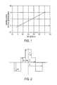
- FIG. 1illustrates the experimental results of the applicant giving the bending losses at a wavelength of 1625 nm with a bending radius of 15 mm in a standard SSMF fiber in relation to the MAC value at a wavelength of 1550 nm. It can be seen that the MAC value influences the bending losses of the fiber and that these bending losses may be reduced by reducing the MAC value.
- a reduction in the MAC value by reducing the mode field diameter and/or by increasing the effective cut-off wavelengthmay lead to overstepping the G.652 standard, making the fiber commercially incompatible with some transmission systems.
- FTTHFiber To The Home systems
- FTTCfibers to the curb
- a transmission system through optical fiberscomprises storage boxes in which fiber overlengths are provided in the case of future interventions; these overlengths are wound in the boxes.
- the single mode fibers in this contextare intended to be wound on increasingly small diameters (so as to reach bending radii as small as 15 mm or 11 mm).
- the fiberrisks being subject to harsher installation constraints than in applications at longer distances, i.e., the presence of accidental bendings related to the low cost of the installation and to the environment. Provision must be made for the presence of accidental bending radii equal to 7.5 mm or even 5 mm.
- U.S. Pat. No. 6,771,865describes a profile of a transmission fiber with reduced bending losses.
- the fiberhas a central core, an annular inner cladding and an optical outer cladding.
- the annular claddingis co-doped with Germanium and Fluorine. The information given in this document does not enable determination of whether or not the fiber meets the criteria laid down by the G.652 standard.
- U.S. Pat. No. 4,852,968describes the profile of a transmission fiber having reduced bending losses.
- this fiberhas a chromatic dispersion which does not meet the criteria of G.652 standard; the G.652 standard requires cancellation of chromatic dispersion at wavelengths of between 1300 nm and 1324 nm, but the fiber described in U.S. Pat. No. 4,852,962 shows cancellation of the chromatic dispersion at the wavelengths of between 1400 nm and 1800 nm.
- WO-A-2004/092794describes a profile of a transmission fiber with reduced bending losses.
- the fiberhas a central core, a first inner cladding, a second buried inner cladding and an outer optical cladding.
- Some of the fiber examples described in this documentalso meet the criteria of the G.652 standard.
- the fiber described in this documentis manufactured by Vapor phase Axial Deposition (VAD) or Chemical Vapor Deposition (CVD) type techniques.
- VADVapor phase Axial Deposition
- CVDChemical Vapor Deposition
- the inventionproposes a fiber profile comprising a central core, a first inner cladding, a deeply buried second inner cladding, and an outer cladding.
- the second inner claddingcontains Germanium.
- Germanium in the deeply buried claddingeven though Germanium is a dopant whose effect is to increase the index of silica, makes it possible to increase the elastic-optical coefficient of the buried cladding. Therefore when stresses are applied to the fiber, in particular when the fiber undergoes bending or micro-bending, the presence of the deeply buried cladding containing Germanium allows to limit the effects of stresses on the changes in refractive index in the fiber. The optical losses are therefore reduced when such stresses are applied to a fiber having a second deeply buried inner cladding containing Germanium.
- an optical transmission fibercomprising:
- the index difference ⁇ n 3 of the second inner cladding with the outer claddingis greater than ⁇ 15 ⁇ 10 ⁇ 3 .
- the index difference between the central core and the first inner cladding( ⁇ n 1 ⁇ n 2 ) lies between 3.9 ⁇ 10 ⁇ 3 and 5.9 ⁇ 10 ⁇ 3 .
- the second buried claddinghas a radius of between 12 ⁇ m and 25 ⁇ m.
- the central corehas a radius of between 3.5 ⁇ m and 4.5 ⁇ m, and shows an index difference with the outer cladding of between 4.2 ⁇ 10 ⁇ 3 and 6.1 ⁇ 10 ⁇ 3 .
- the first inner claddinghas a radius of between 7.5 ⁇ m and 14.5 ⁇ m, and shows an index difference with the outer cladding of between ⁇ 1.2 ⁇ 10 ⁇ 3 and 1.2 ⁇ 10 ⁇ 3 .
- the integral of the central coredefined as:
- the present fibershows a chromatic dispersion slope of 0.093 ps/nm 2 -km or less.
- the present fibershows cancellation of chromatic dispersion at a wavelength of between 1300 nm and 1324 nm.
- the present fiberhas a cabled cut-off wavelength of 1260 nm or less.
- the present fibershows bending losses for a winding of 100 turns around a bending radius of 15 mm, that are 1 dB or less.
- the present fibershows bending losses for a winding of 1 turn around a bend radius of 11 mm, of 0.5 dB or less.
- the present fibershows bending losses for a winding of 1 turn around a bend radius of 5 mm, of 2 dB or less.
- the present fibershows microbending losses, measured by the so-called fixed diameter drum method, of 0.8 dB/km or less.
- the inventionalso concerns a method for manufacturing an optical transmission fiber of the invention, the method comprising the steps of:
- the inventionfurther relates to a Fiber To The Home (FTTH) or Fiber To The Curb (FTTC) optical system comprising at least an optical module or a storage box according to the invention.
- FTTHFiber To The Home
- FTTCFiber To The Curb
- FIG. 1previously described, a graph illustrating the bending losses at a wavelength of 1625 nm with a bending radius of 15 mm in a standard single-mode fiber (SSMF) in relation to the MAC value at a wavelength of 1550 nm;
- SSMFstandard single-mode fiber
- FIG. 2a graph showing the set profile of a single-mode fiber (SMF) according to one embodiment of the invention
- FIGS. 3 a to 3 cgraphs illustrating, for different bending radii, the bending losses at a wavelength of 1625 nm in relation to the MAC value at a wavelength of 1550 nm for different standard single-mode fibers (SSMF) and for different fibers of the invention
- FIGS. 4 a and 4 bgraphs illustrating losses through micro-bending.
- the present fiberhas a central core, a first inner cladding and a second, buried, inner cladding.
- buried claddingis meant a radial portion of the fiber whose refractive index is lower than the index of the outer cladding.
- the second, buried, inner claddinghas an index difference with the outer cladding that is less than ⁇ 3 ⁇ 10 ⁇ 3 and may reach ⁇ 15 ⁇ 10 ⁇ 3 .
- the buried claddingcontains Germanium in a weight concentration of between 0.5% and 7%.
- an optical fiberis obtained by drawing of a preform.
- the preformmay be a glass tube (pure silica) of very high quality which forms part of the outer cladding and surrounds the central core and the inner claddings of the fiber; this tube can then be sleeved or refilled to increase its diameter before proceeding with the drawing operation on a draw tower.
- the tubeis generally mounted horizontally and held in place at its two ends by glass rods in a lathe; the tube is then rotated and locally heated to deposit components determining the composition of the preform. This composition determines the optical characteristics of the future fiber.
- the depositing of components in the tubeis commonly called “doping”, i.e. “impurities” are added to the silica to modify its refractive index.
- impuritiesare added to the silica to modify its refractive index.
- Germanium (Ge) or Phosphorus (P)increase the refractive index of the silica; they are often used to dope the central core of the fiber.
- Fluorine (F) or Boron (B)lower the refractive index of the silica; they are often used to form buried claddings or as co-dopant with Germanium when it is desired to compensate for the increase in refractive index in a photosensitive cladding.
- Fluorinedoes not incorporate easily in silica when heated beyond a certain temperature whereas a high temperature is required to manufacture glass.
- the compromise between a high temperature, required for glass-making, and a low temperature promoting proper incorporation of the Fluorinedoes not make it possible to obtain indexes much lower than that of silica.
- PCVDPCVD
- Germaniumincreases the refractive index of the silica; it is therefore generally highly unadvisable to incorporate the same in a fiber section for which it is sought to obtain a lower refractive index than silica.
- PCVDmakes it possible however to produce a high number of highly reactive Fluorine ions; it then becomes possible to add Germanium to the reaction and nonetheless to obtain an buried inner cladding.
- the present fibercomprises Germanium in the assembly of inner claddings including the cladding whose index is less than ⁇ 3 ⁇ 10 ⁇ 3 .
- the presence of Germanium in the buried claddingmodifies the viscosity of the silica and the elastic-optical coefficient in this said cladding.
- FIG. 2illustrates an index profile for a transmission fiber of the invention.
- the illustrated profileis a set profile, i.e. it represents the theoretical profile of the fiber, the fiber actually obtained after drawing from a preform possibly giving a substantially different profile.
- the single-mode transmission fiber of the inventioncomprises a central core having an index difference ⁇ n 1 with an outer cladding, acting as optical cladding; a first inner cladding having an index difference ⁇ n 2 with the outer cladding; a second inner cladding, deeply buried and having an index difference ⁇ n 3 with the outer cladding.
- the refractive indexes in the central core, in the first cladding and in the second inner claddingare substantially constant over their entire width; the set profile is therefore truly a single-mode fiber.
- the width of the coreis defined by its radius r 1 and the width of the claddings by their respective outer radii r 2 and r 3 .
- the index of the outer claddingis generally taken as reference.
- the index values of the central core, buried claddings and the ringare then given as index differences ⁇ n 1.2.3 .
- the outer claddingis formed of silica, but this outer cladding may be doped to increase or reduce its refractive index, for example to modify the signal propagation characteristics.
- Each section of the fiber profilecan therefore be defined using integrals which associate the variations in indexes with the radius of each fiber section.
- Three integralscan hence be defined for the present fiber, which represent the core surface I 1 , the surface of the first inner cladding I 2 and the surface of the second, buried, inner cladding I 3 .
- the expression “surface”is not to be construed geometrically but corresponds to a value taking two dimensions into account.
- Table I belowgives the limit values of radii and index differences, and the limit values of the integral I 1 that are required so that the fiber shows reduced bending losses and microbending losses whilst meeting the optical propagation criteria of G.652 standard for transmission fibers.
- the values given in the tablecorrespond to the set profiles of the fibers.
- the value of the integral I 1 of the central coreinfluences the shape and size of the fundamental propagation mode of the signal in the fiber.
- An integral value for the central core of between 17 ⁇ 10 ⁇ 3 ⁇ m and 24 ⁇ 10 ⁇ 3 ⁇ mmakes it possible in particular to maintain a mode field diameter that is compatible with the G.652 standard.
- Table II belowgives examples of possible index profiles for an transmission fiber according to the invention.
- the first columnallocates a reference to each profile.
- the following columnsgive the radii values of each section (r 1 to r 3 ); and the following columns give the values of the index differences of each section with the outer cladding ( ⁇ n 1 to ⁇ n 3 ).
- the index valuesare measured at the wavelength of 633 nm.
- the present transmission fiberhaving an index profile such as described previously, shows reduced bending losses and microbending losses at useful wavelengths.
- the present fibermeets the criteria of G.652 standard.
- Tables III and IV belowillustrate the simulated optical characteristics for transmission fibers corresponding to the index profiles in Table II.
- This testuses an array of ten polished needles, of diameter 1.5 mm and spaced apart by 1 cm.
- the fiberis woven across the array orthogonally to the axis of the needles.
- the fiber and the arrayare pressed between two rigid plates coated with a layer of approximately 3 mm of high density polyethylene foam.
- the layers of the assembly(plates, array, fiber) are positioned horizontally and the assembly is covered with a weight of 250 g.
- the last columnindicates the microbending losses measured using the fixed diameter drum method at a wavelength of 1625 nm. This method is described in the technical recommendations of the International Electrotechnical Commission, sub-committee 86A under reference IEC TR-62221.
- the diameter of the drum usedis 60 cm; the drum is covered with extra-fine sandpaper.
- the values of the bending losses BLare indicated at a wavelength of 1625 nm.
- example 1shows a dispersion slope P 0 lying slightly outside the G.652 standard.
- the fiber in examples 2 to 4shows cancellation of chromatic dispersion for a wavelength of between 1300 nm and 1324 nm; this is in agreement with the G.652 standard.
- the fiber in examples 2 to 4also shows, for a wavelength of 1310 nm, a chromatic dispersion slope that is 0.093 ps/nm 2 -km or less; which complies with the G.652 standard.
- the fiber in examples 2 to 4shows a cabled cut-off wavelength that is 1260 nm or less, meeting the criteria of the G.652 standard which requires a cabled cut-off wavelength of 1260 nm or less.
- examples 2 to 4exhibit distinctly improved bending losses with respect to the losses of standard SSMF transmission fiber. The microbending losses are also improved.
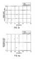
- FIG. 4 ashows microbending losses for fibers manufactured according to the invention, characterized by the pin-array test and measured at a wavelength of 1550 nm, in relation to the MAC value at a wavelength of 1550 nm for different SSMF fibers and for a fiber of the invention.
- FIG. 4 bshows microbending losses using the fixed diameter drum test in relation to the wavelength for a SSMF fiber and for a fiber of the invention having MAC values at a wavelength of 1550 nm of 8.11 and 8.31, respectively.
- FIGS. 4 a and 4 bclearly show that the sensitivity of the present fiber to microbending is markedly reduced with respect to that of a SSMF fiber.
- FIG. 4 athe microbending losses (pin-array test) measured for a fiber of the invention, having a MAC value of 8.44 at a wavelength of 1550 nm, amounts 0.025 dB whereas they are ten times higher for a SSMF fiber having the same MAC value.
- FIG. 4 bmicrobending losses (fixed drum method) for a fiber of the invention increase much more slowly with the wavelength than for a SSMF fiber which has a greater MAC value however at the 1550 nm wavelength.
- the present fiberguarantees a sensitivity to microbending up to long wavelengths, greater than 1650 nm, which is equivalent to the sensitivity which can be guaranteed for a SSMF fiber up to a wavelength of 1550 nm.
- the present transmission fibermay be manufactured by drawing a preform having one of the above-described index profiles.
- Said preform profilesmay be made for example from a sleeve of silica in which layers of doped silica are deposited.
- Depositionmay be made by a Plasma Chemical Vapor Deposition (PCVD) type deposition method mentioned previously.
- PCVDPlasma Chemical Vapor Deposition
- This chemical of deposition in the vapour form activated by plasma (PCVD)is particularly suitable for obtaining a buried inner cladding layer for the present fiber; this buried cladding layer comprising Germanium in a weight concentration of between 0.5% to 7%.
- the weight concentration of Germaniumis preferably between 0.5% and 1.5% since this allows an optimum balance between lower costs and more ease of manufacturing on the one hand and good fiber characteristics on the other hand.
- a pure silica tubeis provided and mounted on a lathe.
- the tubeis then caused to rotate and a gaseous mixture of silica and dopants is injected into the tube.
- the tubepasses through a microwave cavity in which the gaseous mixture is locally heated. Microwave heating generates a plasma by ionization of the gases injected into the tube and the ionized dopants react strongly with the silica particles to cause the depositing of layers of doped silica on the inside of the tube.
- the strong reactivity of the dopants generated by microwave heatingmakes it possible to incorporate a high concentration of dopants in the silica layers.
- the PCVD techniqueallows doping of a silica layer with a high concentration of Fluorine to form deeply buried layers.
- the creation of the second buried claddingis obtained by depositing a layer of silica doped with Fluorine and Germanium; a gaseous mixture containing oxygen O 2 , silica SiCl 4 , Fluorine C 2 F 6 and Germanium GeO 2 is injected into the tube. This gaseous mixture is ionized in the microwave cavity of a PCVD installation, the Fluorine and Germanium ions are incorporated in the silica particles.
- the proportions of injected gasesare monitored so as to obtain a layer of doped silica containing Germanium in a weight concentration of 0.5% to 7%. and Fluorine in a concentration that is required to obtain the targeted refractive index.
- the strong concentration Fluorineensures the required reduction in index for the buried cladding, and the low concentration of Germanium brings the changes in viscosity and elastic-optical coefficient that are required to reduce bending losses and microbending losses in the fiber obtained.
- the transmission fiber according to the inventionmay be used in a transmitting or receiving module in an FTTH or FTTC system or in a high rate and long distance optical transmission cable, with reduced optical losses.
- the fiber of the inventionis compatible with the marketed systems as it meets the G.652 standard.
- overlengths of the fiber according to the inventionmay be wound in storage boxes associated with optical modules of FTTH or FTTC systems, the fiber according to the invention may be wound with a bending radius less than 15 mm, or even less than 5 mm without inducing strong optical losses.
- the fiber according to the inventionis also very suitable for supporting accidental bendings related to its installation at an individual's home, with bending radii ranging down to 5 mm.
- the present inventionis not limited to the embodiments described by way of example.
- a manufacturing method other than PCVDmay be considered provided the method allows the incorporation of Germanium in an buried layer in accordance with the claimed proportions and index differences.
- the fiber according to the inventionmay also be used in applications other than FTTH or FTTC.
Landscapes
- Physics & Mathematics (AREA)
- Chemical & Material Sciences (AREA)
- Engineering & Computer Science (AREA)
- Optics & Photonics (AREA)
- General Physics & Mathematics (AREA)
- Life Sciences & Earth Sciences (AREA)
- General Life Sciences & Earth Sciences (AREA)
- Geochemistry & Mineralogy (AREA)
- Manufacturing & Machinery (AREA)
- Materials Engineering (AREA)
- Organic Chemistry (AREA)
- General Chemical & Material Sciences (AREA)
- Chemical Kinetics & Catalysis (AREA)
- Glass Compositions (AREA)
- Manufacture, Treatment Of Glass Fibers (AREA)
- Optical Fibers, Optical Fiber Cores, And Optical Fiber Bundles (AREA)
Abstract
Description
This application is a continuation of commonly assigned U.S. patent application Ser. No. 12/622,071 for a Single-Mode Optical Fiber, (filed Nov. 19, 2009 and published Mar. 18, 2010, as U.S. Patent Application Publication No. 2010/0067859 A1), now U.S. Pat. No. 7,995,889, which itself is a continuation of commonly assigned U.S. patent application Ser. No. 11/556,895 for a Single Mode Optical Fiber, (filed Nov. 6, 2006, and published Jun. 7, 2007, as U.S. Patent Application Publication No. 2007/0127878 A1), now U.S. Pat. No. 7,623,747, which itself claims the benefit of French Application No. 05/11443 (filed Nov. 10, 2005 at the French Patent Office). Each of the foregoing patent applications, patent application publications, and patents is hereby incorporated by reference in its entirety.
The present invention relates to the field of optical fiber transmissions, and more specifically to a line fiber having reduced bending and microbending losses.
For optical fibers, the index profile is generally qualified in relation to the plotting of a graph showing the function associating the refractive index of the fiber with the radius of the fiber. Conventionally, the distance r to the center of the fiber is shown along the abscissa axis, and the difference between the refractive index and the refractive index of the fiber cladding is shown along the ordinate axis. The index profile is therefore described as “step”, “trapezoid” or “triangular” for graphs respectively showing step, trapezoid or triangular shapes. These curves are generally representative of the theoretical or set profile of the fiber, the stresses of fiber manufacture possibly leading to a substantially different profile.
An optical fiber conventionally consists of an optical core whose function is to transmit and optionally amplify an optical signal, and an optical cladding whose function is to confine the optical signal within the core. For this purpose, the refractive indexes of the core ncand of the cladding ngare such that nc>ng. As is well known, the propagation of an optical signal in a single-mode optical fiber breaks down into a fundamental mode guided in the core, and into secondary modes guided over a certain distance in the core-cladding assembly and called cladding modes.
As line fibers for optical fiber transmission systems, Single Mode Fibers (SMF) are typically used. These fibers show chromatic dispersion and a chromatic dispersion slope meeting specific telecommunications standards.
For the needs of compatibility between the optical systems of different manufacturers, the International Telecommunication Union (ITU) has laid down a standard referenced ITU-T G.652 which must be met by a Standard Single Mode Fiber (SSMF).
This G.652 standard for transmission fibers, recommends inter alia, a range of [8.6; 9.5 μm] for the Mode Field Diameter (MFD) at a wavelength of 1310 nm; a maximum of 1260 nm for the cabled cut-off wavelength; a range of [1300; 1324 nm] for the dispersion cancellation wavelength denoted λ0; a maximum of 0.093 ps/nm2-km for the chromatic dispersion slope. The cabled cut-off wavelength is conventionally measured as the wavelength at which the optical signal is no longer single-mode after propagation over twenty-two meters of fiber, such as defined by sub-committee 86A of the International Electrotechnical Commission under standard IEC 60793-1-44.
Also, for a given fiber, a so-called MAC value is defined as the ratio of the mode field diameter of the fiber at 1550 nm over the effective cut-off wavelength λceffotherwise called cut-off wavelength. The cut-off wavelength is conventionally measured as the wavelength at which the optical signal is no longer single-mode after propagation over two meters of fiber such as defined by sub-committee 86A of the International Electrotechnical Commission under standard IEC 60793-1-44. The MAC value is used to assess fiber performance, in particular to find a compromise between mode field diameter, effective cut-off wavelength and bending losses.
However, a reduction in the MAC value by reducing the mode field diameter and/or by increasing the effective cut-off wavelength, may lead to overstepping the G.652 standard, making the fiber commercially incompatible with some transmission systems.
Adhering to the G.652 standard and the reduction in bending losses is a true challenge for applications of fibers intended for optical fiber systems to homes, called Fiber To The Home systems (FTTH) or fiber optical systems up to the curb or up to the building, so-called fibers to the curb (FTTC).
Indeed, a transmission system through optical fibers comprises storage boxes in which fiber overlengths are provided in the case of future interventions; these overlengths are wound in the boxes. Because of the intention to miniaturize these boxes for FTTH or FTTC applications, the single mode fibers in this context are intended to be wound on increasingly small diameters (so as to reach bending radii as small as 15 mm or 11 mm). Moreover, within the scope of FTTH or FTTC applications, the fiber risks being subject to harsher installation constraints than in applications at longer distances, i.e., the presence of accidental bendings related to the low cost of the installation and to the environment. Provision must be made for the presence of accidental bending radii equal to 7.5 mm or even 5 mm. It is therefore absolutely necessary in order to meet the constraints related to the storage boxes and to the installation constraints that the single mode fibers used for FTTH or FTTC applications have limited bending losses. Nevertheless it is understood that this reduction in bending losses should not be achieved to the detriment of a loss of the single mode character of the signal which would strongly deteriorate the signal or to the detriment of introducing significant junction optical losses.
The publication by S. Matsuo et al. “Bend-Insensitive and Low Splice-Loss Optical Fiber for Indoor Wiring in FTTH”, OFC '04 Proceedings, paper Th13 (2004) describes an index profile for single mode fiber (SMF) which enables a reduction in bending losses. However, this fiber shows a chromatic dispersion of between 10.2 ps/nm-km and 14.1 ps/nm-km which lies outside the G.652 standard.
The publication by I. Sakabe et al. “Enhanced Bending Loss Insensitive Fiber and New Cables for CWDM Access Networks”, 53rdIWCS Proceedings, pp. 112-118 (2004) proposes reducing the Mode Field Diameter to reduce bending losses. This reduction in mode field diameter leads however to overstepping the G.652 standard.
The publication by K. Bandou et al. “Development of Premise Optical Wiring Components Using Hole-Assisted Fiber” 53rdIWCS Proceedings, pp. 119-122 (2004) proposes a hole fiber having the optical characteristics of a SSMF fiber with reduced bending losses. The cost of manufacturing said fiber and the high attenuation levels at the present time (>0.25 dB/km) make it difficult to be given commercial use in FTTH systems.
The publication by T. Yokokawa et al. “Ultra-Low Loss and Bend Insensitive Pure-Silica-Core Fiber Complying with G.652 C/D and its Applications to a Loose Tube Cable”, 53rdIWCS Proceedings, pp 150-155 (2004) proposes a pure silica core fiber PSCF, having reduced transmission and bending losses, but with a reduced mode field diameter lying outside the G.652 standard.
U.S. Pat. No. 6,771,865 describes a profile of a transmission fiber with reduced bending losses. The fiber has a central core, an annular inner cladding and an optical outer cladding. The annular cladding is co-doped with Germanium and Fluorine. The information given in this document does not enable determination of whether or not the fiber meets the criteria laid down by the G.652 standard.
U.S. Pat. No. 4,852,968 describes the profile of a transmission fiber having reduced bending losses. However this fiber has a chromatic dispersion which does not meet the criteria of G.652 standard; the G.652 standard requires cancellation of chromatic dispersion at wavelengths of between 1300 nm and 1324 nm, but the fiber described in U.S. Pat. No. 4,852,962 shows cancellation of the chromatic dispersion at the wavelengths of between 1400 nm and 1800 nm.
WO-A-2004/092794 describes a profile of a transmission fiber with reduced bending losses. The fiber has a central core, a first inner cladding, a second buried inner cladding and an outer optical cladding. Some of the fiber examples described in this document also meet the criteria of the G.652 standard. The fiber described in this document is manufactured by Vapor phase Axial Deposition (VAD) or Chemical Vapor Deposition (CVD) type techniques. The fiber described in this document does not however identify the problems of microbending losses.
There is therefore a need for a transmission fiber with which it is possible to meet the criteria of the G.652 standard, i.e. which can be given commercial use in transmission systems of the FTTH or FTTC type, and which shows both reduced bending losses and reduced microbending losses. In FTTH or FTTC applications, fibers are subjected to higher bending and microbending stresses than in long-haul transmission applications. Indeed, in FTTH or FTTC applications, overlengths of fibers are generally wound in increasingly miniaturized storage boxes; moreover the fiber will be subject to significant bending stresses related to the environment of its installation.
For this purpose, the invention proposes a fiber profile comprising a central core, a first inner cladding, a deeply buried second inner cladding, and an outer cladding. The second inner cladding contains Germanium.
The presence of Germanium in the deeply buried cladding, even though Germanium is a dopant whose effect is to increase the index of silica, makes it possible to increase the elastic-optical coefficient of the buried cladding. Therefore when stresses are applied to the fiber, in particular when the fiber undergoes bending or micro-bending, the presence of the deeply buried cladding containing Germanium allows to limit the effects of stresses on the changes in refractive index in the fiber. The optical losses are therefore reduced when such stresses are applied to a fiber having a second deeply buried inner cladding containing Germanium.
More particularly, the invention proposes an optical transmission fiber comprising:
- a central core having an index difference Δn1with an outer optical cladding;
- a first inner cladding having an index difference Δn2with the outer cladding;
- a second, buried, inner cladding having an index difference Δn3with the outer cladding of less than −3·10−3, and containing Germanium in a weight concentration of between 0.5% and 7%.
According to one characteristic, the index difference Δn3of the second inner cladding with the outer cladding is greater than −15·10−3.
According to another characteristic, the index difference between the central core and the first inner cladding (Δn1−Δn2) lies between 3.9·10−3and 5.9·10−3.
According to another characteristic, the second buried cladding has a radius of between 12 μm and 25 μm.
According to another characteristic, the central core has a radius of between 3.5 μm and 4.5 μm, and shows an index difference with the outer cladding of between 4.2·10−3and 6.1·10−3.
According to another characteristic, the first inner cladding has a radius of between 7.5 μm and 14.5 μm, and shows an index difference with the outer cladding of between −1.2·10−3and 1.2·10−3.
According to another characteristic, the integral of the central core, defined as:
lies between 17·10−3μm and 24·10−3μm.
According to another characteristic, at a wavelength of 1310 nm, the present fiber shows a chromatic dispersion slope of 0.093 ps/nm2-km or less.
According to another characteristic, the present fiber shows cancellation of chromatic dispersion at a wavelength of between 1300 nm and 1324 nm.
According to another characteristic, the present fiber has a cabled cut-off wavelength of 1260 nm or less.
According to another characteristic, at a wavelength of 1625 nm, the present fiber shows bending losses for a winding of 100 turns around a bending radius of 15 mm, that are 1 dB or less.
According to another characteristic, at a wavelength of 1625 nm, the present fiber shows bending losses for a winding of 1 turn around a bend radius of 11 mm, of 0.5 dB or less.
According to another characteristic, at a wavelength of 1625 nm, the present fiber shows bending losses for a winding of 1 turn around a bend radius of 5 mm, of 2 dB or less.
According to another characteristic, up to a wavelength of 1625 nm, the present fiber shows microbending losses, measured by the so-called fixed diameter drum method, of 0.8 dB/km or less.
The invention also concerns a method for manufacturing an optical transmission fiber of the invention, the method comprising the steps of:
- providing a silica tube and positioning said tube on a lathe;
- injecting a gaseous mixture of oxygen O2, silica SiCl4, Fluorine C2F6and Germanium GeO2in the tube;
- ionizing the gaseous mixture to obtain a plasma by microwave heating to deposit a layer of doped silica forming the second, buried, inner cladding;
- successively injecting gaseous mixtures and ionizing said mixtures to deposit layers of doped silica forming the first inner cladding and the central core.
The invention further relates to a Fiber To The Home (FTTH) or Fiber To The Curb (FTTC) optical system comprising at least an optical module or a storage box according to the invention.
Other characteristics and advantages of the invention will become apparent on reading the following description of embodiments of the invention given by way of example and with reference to the appended drawings showing:
The present fiber has a central core, a first inner cladding and a second, buried, inner cladding. By buried cladding is meant a radial portion of the fiber whose refractive index is lower than the index of the outer cladding. The second, buried, inner cladding has an index difference with the outer cladding that is less than −3·10−3and may reach −15·10−3. Also, the buried cladding contains Germanium in a weight concentration of between 0.5% and 7%.
As known per se, an optical fiber is obtained by drawing of a preform. For example the preform may be a glass tube (pure silica) of very high quality which forms part of the outer cladding and surrounds the central core and the inner claddings of the fiber; this tube can then be sleeved or refilled to increase its diameter before proceeding with the drawing operation on a draw tower. To manufacture the preform, the tube is generally mounted horizontally and held in place at its two ends by glass rods in a lathe; the tube is then rotated and locally heated to deposit components determining the composition of the preform. This composition determines the optical characteristics of the future fiber.
The depositing of components in the tube is commonly called “doping”, i.e. “impurities” are added to the silica to modify its refractive index. Hence, Germanium (Ge) or Phosphorus (P) increase the refractive index of the silica; they are often used to dope the central core of the fiber. Also, Fluorine (F) or Boron (B) lower the refractive index of the silica; they are often used to form buried claddings or as co-dopant with Germanium when it is desired to compensate for the increase in refractive index in a photosensitive cladding.
A preform with an buried cladding is difficult to manufacture. Fluorine does not incorporate easily in silica when heated beyond a certain temperature whereas a high temperature is required to manufacture glass. The compromise between a high temperature, required for glass-making, and a low temperature promoting proper incorporation of the Fluorine does not make it possible to obtain indexes much lower than that of silica.
It is proposed to manufacture the preform of the present fiber using a PCVD technique (Plasma Chemical Vapor Deposition) since it allows reactions at lower temperatures than conventional techniques (CVD, VAD, OVD) by ionizing the reaction components. Said manufacturing technique is described in documents US RE 30.635 and U.S. Pat. No. 4,314,833; it allows major incorporation of Fluorine in the silica in order to form deeply buried claddings.
The use of the PCVD technique to manufacture the inventive fiber also makes it possible to add Germanium to the buried cladding. As indicated previously, Germanium increases the refractive index of the silica; it is therefore generally highly unadvisable to incorporate the same in a fiber section for which it is sought to obtain a lower refractive index than silica. PCVD makes it possible however to produce a high number of highly reactive Fluorine ions; it then becomes possible to add Germanium to the reaction and nonetheless to obtain an buried inner cladding.
Therefore, the present fiber comprises Germanium in the assembly of inner claddings including the cladding whose index is less than −3·10−3. The presence of Germanium in the buried cladding modifies the viscosity of the silica and the elastic-optical coefficient in this said cladding.
The single-mode transmission fiber of the invention comprises a central core having an index difference Δn1with an outer cladding, acting as optical cladding; a first inner cladding having an index difference Δn2with the outer cladding; a second inner cladding, deeply buried and having an index difference Δn3with the outer cladding. The refractive indexes in the central core, in the first cladding and in the second inner cladding are substantially constant over their entire width; the set profile is therefore truly a single-mode fiber. The width of the core is defined by its radius r1and the width of the claddings by their respective outer radii r2and r3.
To define a set index profile for an optical fiber, the index of the outer cladding is generally taken as reference. The index values of the central core, buried claddings and the ring are then given as index differences Δn1.2.3. Generally, the outer cladding is formed of silica, but this outer cladding may be doped to increase or reduce its refractive index, for example to modify the signal propagation characteristics.
Each section of the fiber profile can therefore be defined using integrals which associate the variations in indexes with the radius of each fiber section.
Three integrals can hence be defined for the present fiber, which represent the core surface I1, the surface of the first inner cladding I2and the surface of the second, buried, inner cladding I3. The expression “surface” is not to be construed geometrically but corresponds to a value taking two dimensions into account. These three integrals can be expressed as follows:
Table I below gives the limit values of radii and index differences, and the limit values of the integral I1that are required so that the fiber shows reduced bending losses and microbending losses whilst meeting the optical propagation criteria of G.652 standard for transmission fibers. The values given in the table correspond to the set profiles of the fibers.
| TABLE I | ||||||||
| r1 | r2 | r3 | Δn1 | Δn2 | Δn3 | I1 | ||
| (μm) | (μm) | (μm) | r1/r2 | (.103) | (.103) | (.103) | Δn1 − Δn2 | (μm .103) |
| 3.5 | 7.5 | 12.0 | 0.27 | 4.2 | −1.2 | −15 | 3.9 | 17 |
| 4.5 | 14.5 | 25.0 | 0.5 | 6.2 | 1.2 | −3 | 5.9 | 24 |
The value of the integral I1of the central core influences the shape and size of the fundamental propagation mode of the signal in the fiber. An integral value for the central core of between 17·10−3μm and 24·10−3μm makes it possible in particular to maintain a mode field diameter that is compatible with the G.652 standard.
Table II below gives examples of possible index profiles for an transmission fiber according to the invention. The first column allocates a reference to each profile. The following columns give the radii values of each section (r1to r3); and the following columns give the values of the index differences of each section with the outer cladding (Δn1to Δn3). The index values are measured at the wavelength of 633 nm.
| TABLE II | ||||||
| r1 | r2 | r3 | Δn1 | Δn2 | Δn3 | |
| Example | (μm) | (μm) | (μm) | (.103) | (.103) | (.103) |
| 1 | 2.86 | 6.90 | 13.24 | 5.41 | 2.00 | −3.70 |
| 2 | 3.86 | 9.50 | 15 | 5.16 | 0.69 | −5.0 |
| 3 | 4.02 | 9.55 | 15 | 5.31 | 0.45 | −5.0 |
| 4 | 3.86 | 8.66 | 15 | 5.41 | 0.85 | −0.5 |
The present transmission fiber, having an index profile such as described previously, shows reduced bending losses and microbending losses at useful wavelengths.
In addition, the present fiber meets the criteria of G.652 standard.
Tables III and IV below illustrate the simulated optical characteristics for transmission fibers corresponding to the index profiles in Table II.
In Table III, column one reproduces the references of Table II. The following columns, for each fiber profile, give the values of the effective cut-off wavelength λCeff, cabled cut-off wavelength λCC, mode field diameters 2W02 for the wavelengths 1310 nm and 1550 nm, the cancellation wavelength of the chromatic dispersion λ0, the dispersion slope P0at λ0, the chromatic dispersions C for thewavelengths 1550 nm and 1625 nm.
In Table IV, column one reproduces the references of Table III. The following column gives the MAC values at a wavelength of 1550 nm. The three following columns give the values for the bending losses BL for the respective bending radii of 5, 11 and 15 mm at a wavelength of 1625 nm. The following column, for a radius of 15 mm, gives the relative bending losses normalized with respect to the standard bending losses of a SSMF fiber having the same MAC value at a wavelength of 1550 nm. The last-but-one column gives the microbending losses obtained with the pin-array test (10 pins of 1.5 mm) at a wavelength of 1550 nm.
This test uses an array of ten polished needles, of diameter 1.5 mm and spaced apart by 1 cm. The fiber is woven across the array orthogonally to the axis of the needles. The fiber and the array are pressed between two rigid plates coated with a layer of approximately 3 mm of high density polyethylene foam. The layers of the assembly (plates, array, fiber) are positioned horizontally and the assembly is covered with a weight of 250 g. The last column indicates the microbending losses measured using the fixed diameter drum method at a wavelength of 1625 nm. This method is described in the technical recommendations of the International Electrotechnical Commission, sub-committee 86A under reference IEC TR-62221. The diameter of the drum used is 60 cm; the drum is covered with extra-fine sandpaper. The values of the bending losses BL are indicated at a wavelength of 1625 nm.
| TABLE III | ||||||||
| 2W02 @ | 2W02 @ | C @ | C @ | |||||
| λCeff | λCC | 1310 | 1550 nm | λ0 | P0 | 1550 nm | 1625 nm | |
| N° | (μm) | (μm) | (μm2) | (μm2) | (nm) | (ps/nm2-km) | (ps/nm-km) | (ps/nm-km) |
| 1 | 1.13 | <1.26 | 9.10 | 10.18 | 1308 | 0.097 | 19.2 | 23.9 |
| 2 | 1.23 | <1.26 | 9.16 | 10.36 | 1312 | 0.091 | 18.1 | 22.9 |
| 3 | 1.25 | <1.26 | 9.01 | 10.13 | 1318 | 0.089 | 17.3 | 22.0 |
| 4 | 1.25 | <1.26 | 9.00 | 10.08 | 1318 | 0.091 | 17.8 | 22.5 |
| TABLE IV | |||||||
| BL | BL | BL | BLμ Pin- | BLμ Drum | |||
| R = 5 mm | R = 11 mm | R = 15 mm | BLrel | array test | method | ||
| MAC @ | @ 1625 nm | @ 1625 nm | @ 1625 nm | R = 15 mm | @ 1550 nm | @ 1625 nm | |
| N° | 1550 nm | (dB/turn) | (dB/turn) | (dB/100 turns) | @ 1625 nm | (dB) | (dB/km) |
| 1 | 9.0 | ≦5 | ≦2 | 1/5 | |||
| 2 | 8.4 | 2 | ≦0.5 | ≦1 | 1/5 | 0.025 | ≦0.8 |
| 3 | 8.1 | 1 | ≦0.1 | ≦0.4 | 1/5 | ≦0.025 | ≦0.8 |
| 4 | 8.1 | 1 | ≦0.1 | ≦0.4 | 1/5 | ≦0.025 | ≦0.8 |
It can be seen in Table III that examples 2 to 4 indeed comply with the G.652 standard, example 1 shows a dispersion slope P0lying slightly outside the G.652 standard.
In particular, the fiber in examples 2 to 4 shows cancellation of chromatic dispersion for a wavelength of between 1300 nm and 1324 nm; this is in agreement with the G.652 standard. The fiber in examples 2 to 4 also shows, for a wavelength of 1310 nm, a chromatic dispersion slope that is 0.093 ps/nm2-km or less; which complies with the G.652 standard. Also the fiber in examples 2 to 4 shows a cabled cut-off wavelength that is 1260 nm or less, meeting the criteria of the G.652 standard which requires a cabled cut-off wavelength of 1260 nm or less.
In addition, it can be seen in table IV that examples 2 to 4 exhibit distinctly improved bending losses with respect to the losses of standard SSMF transmission fiber. The microbending losses are also improved.
The graphs inFIGS. 3 a,3band3cshow bending loss measurements obtained with fibers manufactured according to the invention and for standard fibers, with bending radii of R=5 mm, R=11 mm and R=15 mm at a wavelength of 1625 nm. The bending losses here are given at the end of one loop (for R=5 mm and R=11 mm) or at the end of 100 loops (for R=15 mm).
Also, the graphs inFIGS. 4 aand4bclearly show that the sensitivity of the present fiber to microbending is markedly reduced with respect to that of a SSMF fiber. It can be seen inFIG. 4 athat the microbending losses (pin-array test) measured for a fiber of the invention, having a MAC value of 8.44 at a wavelength of 1550 nm, amounts 0.025 dB whereas they are ten times higher for a SSMF fiber having the same MAC value. It can also be seen inFIG. 4 bthat microbending losses (fixed drum method) for a fiber of the invention increase much more slowly with the wavelength than for a SSMF fiber which has a greater MAC value however at the 1550 nm wavelength. In this graph it can be seen that the present fiber guarantees a sensitivity to microbending up to long wavelengths, greater than 1650 nm, which is equivalent to the sensitivity which can be guaranteed for a SSMF fiber up to a wavelength of 1550 nm.
The present transmission fiber may be manufactured by drawing a preform having one of the above-described index profiles. Said preform profiles may be made for example from a sleeve of silica in which layers of doped silica are deposited. Deposition may be made by a Plasma Chemical Vapor Deposition (PCVD) type deposition method mentioned previously. This chemical of deposition in the vapour form activated by plasma (PCVD) is particularly suitable for obtaining a buried inner cladding layer for the present fiber; this buried cladding layer comprising Germanium in a weight concentration of between 0.5% to 7%. The weight concentration of Germanium is preferably between 0.5% and 1.5% since this allows an optimum balance between lower costs and more ease of manufacturing on the one hand and good fiber characteristics on the other hand.
A pure silica tube is provided and mounted on a lathe. The tube is then caused to rotate and a gaseous mixture of silica and dopants is injected into the tube. The tube passes through a microwave cavity in which the gaseous mixture is locally heated. Microwave heating generates a plasma by ionization of the gases injected into the tube and the ionized dopants react strongly with the silica particles to cause the depositing of layers of doped silica on the inside of the tube.
The strong reactivity of the dopants generated by microwave heating, makes it possible to incorporate a high concentration of dopants in the silica layers. For Fluorine in particular, which is difficult to incorporate into silica with local burner heating, the PCVD technique allows doping of a silica layer with a high concentration of Fluorine to form deeply buried layers.
Within the scope of the invention, the creation of the second buried cladding is obtained by depositing a layer of silica doped with Fluorine and Germanium; a gaseous mixture containing oxygen O2, silica SiCl4, Fluorine C2F6and Germanium GeO2is injected into the tube. This gaseous mixture is ionized in the microwave cavity of a PCVD installation, the Fluorine and Germanium ions are incorporated in the silica particles.
The proportions of injected gases are monitored so as to obtain a layer of doped silica containing Germanium in a weight concentration of 0.5% to 7%. and Fluorine in a concentration that is required to obtain the targeted refractive index.
The strong concentration Fluorine ensures the required reduction in index for the buried cladding, and the low concentration of Germanium brings the changes in viscosity and elastic-optical coefficient that are required to reduce bending losses and microbending losses in the fiber obtained.
The transmission fiber according to the invention may be used in a transmitting or receiving module in an FTTH or FTTC system or in a high rate and long distance optical transmission cable, with reduced optical losses. The fiber of the invention is compatible with the marketed systems as it meets the G.652 standard. In particular, overlengths of the fiber according to the invention may be wound in storage boxes associated with optical modules of FTTH or FTTC systems, the fiber according to the invention may be wound with a bending radius less than 15 mm, or even less than 5 mm without inducing strong optical losses. The fiber according to the invention is also very suitable for supporting accidental bendings related to its installation at an individual's home, with bending radii ranging down to 5 mm.
Evidently, the present invention is not limited to the embodiments described by way of example. In particular, a manufacturing method other than PCVD may be considered provided the method allows the incorporation of Germanium in an buried layer in accordance with the claimed proportions and index differences. In addition, the fiber according to the invention may also be used in applications other than FTTH or FTTC.
Claims (38)
1. An optical transmission fiber, comprising:
a central core and an outer optical cladding, the central core having a first refractive index difference (Δn1) with the outer cladding;
a first inner cladding surrounding the central core, the first inner cladding having a second refractive index difference (Δn2) with the outer cladding; and
a second, buried, inner cladding disposed between the first inner cladding and the outer cladding, the second inner cladding having a third refractive index difference (Δn3) with the outer cladding;
wherein the optical transmission fiber has a cabled cut-off wavelength of 1260 nanometers or less;
wherein the optical transmission fiber has a dispersion cancellation wavelength (λ0) between 1300 nanometers and 1324 nanometers; and
wherein, at a wavelength of 1625 nanometers, the optical transmission fiber has bending losses of 2 dB or less for a winding of one turn around a bending radius of 5 millimeters.
2. The optical transmission fiber according toclaim 1 , wherein, at a wavelength of 1310 nanometers, the optical transmission fiber has a positive chromatic dispersion slope.
3. The optical transmission fiber according toclaim 1 , wherein, at a wavelength of 1625 nanometers, the optical transmission fiber has bending losses of less than about 1 dB for a winding of one turn around a bending radius of 5 millimeters.
4. The optical transmission fiber according toclaim 1 , wherein, in accordance with the ITU-T G.652 standard, at a wavelength of 1310 nanometers, the optical transmission fiber has a nominal mode field diameter (MFD) of between 8.6 microns and 9.5 microns.
5. The optical transmission fiber according toclaim 1 , wherein the central core has a maximum first refractive index difference (Δn1) with the outer cladding that is between 4.2×10⁻³and 6.1×10⁻³.
6. The optical transmission fiber according toclaim 1 , wherein the central core possesses a step refractive-index profile.
7. The optical transmission fiber according toclaim 1 , wherein:
the first inner cladding immediately surrounds the central core; and
the first inner cladding has a second refractive index difference (Δn2) with the outer cladding that is −1.2×10⁻³or greater.
8. The optical transmission fiber according toclaim 1 , wherein the refractive index difference between the central core and the first inner cladding (Δn1−Δn2) is between about 3.9×10⁻³and 5.9×10⁻³.
9. The optical transmission fiber according toclaim 1 , wherein the second inner cladding has a third refractive index difference (Δn3) with the outer cladding that is less than −3×10⁻³.
10. The optical transmission fiber according toclaim 9 , wherein the second inner cladding is doped with between about 0.5 and 7 weight percent Germanium.
11. The optical transmission fiber according toclaim 1 , wherein the optical transmission fiber satisfies the criteria of the ITU-T G.652 recommendations.
12. A cable containing one or more optical transmission fibers according toclaim 1 .
13. An optical module or a storage box receiving at least a portion of the optical transmission fiber according toclaim 1 .
14. A Fiber-To-The-Home (FTTH) or a Fiber-To-The-Curb (FTTC) system comprising at least a portion of the optical transmission fiber according toclaim 1 .
15. An optical transmission fiber, comprising:
a central core and an outer optical cladding, the central core having a first refractive index difference (Δn1) with the outer cladding;
a first inner cladding surrounding the central core, the first inner cladding having a second refractive index difference (Δn2) with the outer cladding; and
a second, buried, inner cladding disposed between the first inner cladding and the outer cladding, the second inner cladding having a third refractive index difference (Δn3) with the outer cladding;
wherein the optical transmission fiber has a cabled cut-off wavelength of 1260 nanometers or less;
wherein the optical transmission fiber has a dispersion cancellation wavelength (λ0) between 1300 nanometers and 1324 nanometers; and
wherein, at a wavelength of 1625 nanometers, the optical transmission fiber has bending losses of 0.5 dB or less for a winding of one turn around a bending radius of 11 millimeters.
16. The optical transmission fiber according toclaim 15 , wherein, at a wavelength of 1310 nanometers, the optical transmission fiber has a positive chromatic dispersion slope of 0.093 ps/(nm2·km) or less.
17. The optical transmission fiber according toclaim 15 , wherein, at a wavelength of 1625 nanometers, the optical transmission fiber has bending losses of less than about 0.1 dB for a winding of one turn around a bending radius of 11 millimeters.
18. The optical transmission fiber according toclaim 15 , wherein, in accordance with the ITU-T G.652 standard, at a wavelength of 1310 nanometers, the optical transmission fiber has a mode field diameter (MFD) of between 8.6 microns and 9.5 microns, with a tolerance of +/−0.6 micron.
19. The optical transmission fiber according toclaim 15 , wherein the central core has a maximum first refractive index difference (Δn1) with the outer cladding that is between 4.2×10⁻³and 6.2×10⁻³.
20. The optical transmission fiber according toclaim 15 , wherein the central core possesses a step refractive-index profile.
21. The optical transmission fiber according toclaim 15 , wherein:
the first inner cladding immediately surrounds the central core; and
the first inner cladding has a second refractive index difference (Δn2) with the outer cladding that is between −1.2×10⁻³and 1.2×10⁻³.
22. The optical transmission fiber according toclaim 15 , wherein the second inner cladding has a third refractive index difference (Δn3) with the outer cladding that is between −3×10⁻³and −15×10−3.
23. The optical transmission fiber according toclaim 22 , wherein the second inner cladding is doped with Germanium.
24. The optical transmission fiber according toclaim 15 , wherein the optical transmission fiber satisfies the criteria of the ITU-T G.652 recommendations.
25. A cable containing one or more optical transmission fibers according toclaim 15 .
26. A Fiber-To-The-Home (FTTH) or a Fiber-To-The-Curb (FTTC) system comprising at least a portion of the optical transmission fiber according toclaim 15 .
27. An optical transmission fiber, comprising:
a central core and an outer optical cladding, the central core having a first refractive index difference (Δn1) with the outer cladding;
a first inner cladding surrounding the central core, the first inner cladding having a second refractive index difference (Δn2) with the outer cladding; and
a second, buried, inner cladding disposed between the first inner cladding and the outer cladding, the second inner cladding having a third refractive index difference (Δn3) with the outer cladding;
wherein the optical transmission fiber has a cabled cut-off wavelength of 1260 nanometers or less;
wherein the optical transmission fiber has a dispersion cancellation wavelength (λ0) between 1300 nanometers and 1324 nanometers; and
wherein, at a wavelength of 1625 nanometers, the optical transmission fiber has bending losses of 1 dB or less for a winding of 100 turns around a bending radius of 15 millimeters.
28. The optical transmission fiber according toclaim 27 , wherein, at a wavelength of 1625 nanometers, the optical transmission fiber has bending losses of less than about 0.4 dB for a winding of 100 turns around a bending radius of 15 millimeters.
29. The optical transmission fiber according toclaim 27 , wherein, in accordance with the ITU-T G.652 standard, at a wavelength of 1310 nanometers, the optical transmission fiber has a nominal mode field diameter (MFD) of between 8.6 microns and 9.5 microns.
30. The optical transmission fiber according toclaim 27 , wherein the central core has a first refractive index difference (Δn1) with the outer cladding that is between 4.2×10⁻³and 6.1×10⁻³.
31. The optical transmission fiber according toclaim 27 , wherein the central core possesses a step refractive-index profile.
32. The optical transmission fiber according toclaim 27 , wherein:
the first inner cladding immediately surrounds the central core; and
the first inner cladding has a second refractive index difference (Δn2) with the outer cladding that is −1.2×10⁻³or greater.
33. The optical transmission fiber according toclaim 27 , wherein the refractive index difference between the central core and the first inner cladding (Δn1−Δn2) is between about 3.9×10⁻³and 5.9×10⁻³.
34. The optical transmission fiber according toclaim 27 , wherein the second inner cladding has a third refractive index difference (Δn3) with the outer cladding that is less than −3×10⁻³.
35. The optical transmission fiber according toclaim 34 , wherein the second inner cladding is doped with at least about 0.5 weight percent Germanium.
36. The optical transmission fiber according toclaim 27 , wherein the optical transmission fiber satisfies the criteria of the ITU-T G.652 recommendations.
37. A cable containing one or more optical transmission fibers according toclaim 27 .
38. A Fiber-To-The-Home (FTTH) or a Fiber-To-The-Curb (FTTC) system comprising at least a portion of the optical transmission fiber according toclaim 27 .
Priority Applications (1)
| Application Number | Priority Date | Filing Date | Title |
|---|---|---|---|
| US13/197,042US8837889B2 (en) | 2005-11-10 | 2011-08-03 | Single mode optical fiber |
Applications Claiming Priority (6)
| Application Number | Priority Date | Filing Date | Title |
|---|---|---|---|
| FR05/11443 | 2005-11-10 | ||
| FR0511443AFR2893149B1 (en) | 2005-11-10 | 2005-11-10 | OPTICAL FIBER MONOMODE. |
| FR0511443 | 2005-11-10 | ||
| US11/556,895US7623747B2 (en) | 2005-11-10 | 2006-11-06 | Single mode optical fiber |
| US12/622,071US7995889B2 (en) | 2005-11-10 | 2009-11-19 | Single mode optical fiber |
| US13/197,042US8837889B2 (en) | 2005-11-10 | 2011-08-03 | Single mode optical fiber |
Related Parent Applications (1)
| Application Number | Title | Priority Date | Filing Date |
|---|---|---|---|
| US12/622,071ContinuationUS7995889B2 (en) | 2005-11-10 | 2009-11-19 | Single mode optical fiber |
Publications (2)
| Publication Number | Publication Date |
|---|---|
| US20110286710A1 US20110286710A1 (en) | 2011-11-24 |
| US8837889B2true US8837889B2 (en) | 2014-09-16 |
Family
ID=36613515
Family Applications (3)
| Application Number | Title | Priority Date | Filing Date |
|---|---|---|---|
| US11/556,895ActiveUS7623747B2 (en) | 2005-11-10 | 2006-11-06 | Single mode optical fiber |
| US12/622,071ActiveUS7995889B2 (en) | 2005-11-10 | 2009-11-19 | Single mode optical fiber |
| US13/197,042Active2028-04-30US8837889B2 (en) | 2005-11-10 | 2011-08-03 | Single mode optical fiber |
Family Applications Before (2)
| Application Number | Title | Priority Date | Filing Date |
|---|---|---|---|
| US11/556,895ActiveUS7623747B2 (en) | 2005-11-10 | 2006-11-06 | Single mode optical fiber |
| US12/622,071ActiveUS7995889B2 (en) | 2005-11-10 | 2009-11-19 | Single mode optical fiber |
Country Status (12)
| Country | Link |
|---|---|
| US (3) | US7623747B2 (en) |
| EP (1) | EP1785754B1 (en) |
| JP (1) | JP2007140510A (en) |
| KR (1) | KR101273759B1 (en) |
| CN (1) | CN1982928B (en) |
| AT (1) | ATE467142T1 (en) |
| DE (1) | DE602006014078D1 (en) |
| DK (1) | DK1785754T3 (en) |
| ES (1) | ES2344992T3 (en) |
| FR (1) | FR2893149B1 (en) |
| PL (1) | PL1785754T3 (en) |
| PT (1) | PT1785754E (en) |
Cited By (6)
| Publication number | Priority date | Publication date | Assignee | Title |
|---|---|---|---|---|
| EP3012235A3 (en)* | 2014-10-21 | 2016-06-15 | OFS Fitel, LLC (a Delaware Limited Liability Company) | Low loss optical fiber and method of making the same |
| US9816179B2 (en) | 2013-07-01 | 2017-11-14 | Draka Comteq, B.V. | Plasma deposition process with removal of substrate tube |
| US10884213B1 (en)* | 2019-11-14 | 2021-01-05 | Prysmian S.P.A. | Optical-fiber ribbon with distorted sinusoidal adhesive pattern and method therefor |
| US11442238B2 (en) | 2020-12-22 | 2022-09-13 | Prysmian S.P.A. | Optical-fiber ribbon with spaced optical-fiber units |
| US11460652B2 (en) | 2020-12-22 | 2022-10-04 | Prysmian S.P.A. | Optical-fiber ribbon with adhesive-free gaps |
| US11860429B2 (en) | 2020-12-22 | 2024-01-02 | Prysmian S.P.A. | Optical-fiber ribbon with spaced optical-fiber units |
Families Citing this family (152)
| Publication number | Priority date | Publication date | Assignee | Title |
|---|---|---|---|---|
| FR2893149B1 (en) | 2005-11-10 | 2008-01-11 | Draka Comteq France | OPTICAL FIBER MONOMODE. |
| FR2899693B1 (en) | 2006-04-10 | 2008-08-22 | Draka Comteq France | OPTICAL FIBER MONOMODE. |
| US7620282B2 (en)* | 2006-08-31 | 2009-11-17 | Corning Incorporated | Low bend loss single mode optical fiber |
| DK1930753T3 (en)* | 2006-12-04 | 2015-03-30 | Draka Comteq Bv | Optical fiber having a high Brillouin threshold strength and low bending |
| AU2008213831B2 (en)* | 2007-02-05 | 2012-12-20 | Ofs Fitel, Llc | Selectively pumping a gain-doped region of an optical fiber |
| KR20080100057A (en)* | 2007-05-11 | 2008-11-14 | 주성엔지니어링(주) | Method for manufacturing crystalline silicon solar cell, apparatus and system for manufacturing same |
| JP2009015294A (en)* | 2007-06-05 | 2009-01-22 | Furukawa Electric Co Ltd:The | Holey fiber and method for manufacturing holey fiber |
| US8165439B2 (en) | 2007-11-09 | 2012-04-24 | Draka Comteq, B.V. | ADSS cables with high-performance optical fiber |
| US8031997B2 (en) | 2007-11-09 | 2011-10-04 | Draka Comteq, B.V. | Reduced-diameter, easy-access loose tube cable |
| US8041167B2 (en) | 2007-11-09 | 2011-10-18 | Draka Comteq, B.V. | Optical-fiber loose tube cables |
| US8467650B2 (en) | 2007-11-09 | 2013-06-18 | Draka Comteq, B.V. | High-fiber-density optical-fiber cable |
| US8145026B2 (en) | 2007-11-09 | 2012-03-27 | Draka Comteq, B.V. | Reduced-size flat drop cable |
| US8041168B2 (en) | 2007-11-09 | 2011-10-18 | Draka Comteq, B.V. | Reduced-diameter ribbon cables with high-performance optical fiber |
| US8081853B2 (en) | 2007-11-09 | 2011-12-20 | Draka Comteq, B.V. | Single-fiber drop cables for MDU deployments |
| DK2206001T3 (en)* | 2007-11-09 | 2014-07-07 | Draka Comteq Bv | Optical fiber resistant to microbending |
| NL1034923C2 (en) | 2008-01-16 | 2009-07-20 | Draka Comteq Bv | Optical cable. |
| CN102221726A (en)* | 2008-02-22 | 2011-10-19 | 住友电气工业株式会社 | Optical fiber cable and optical cable |
| US8422843B2 (en)* | 2008-03-28 | 2013-04-16 | Adc Telecommunications, Inc. | Multi-fiber fiber optic cable |
| FR2929716B1 (en)* | 2008-04-04 | 2011-09-16 | Draka Comteq France Sa | OPTICAL FIBER WITH DISPERSION OFFSET. |
| FR2929717B1 (en) | 2008-04-08 | 2010-09-10 | Draka Comteq France | OPTICAL HOUSING |
| FR2930997B1 (en)* | 2008-05-06 | 2010-08-13 | Draka Comteq France Sa | OPTICAL FIBER MONOMODE |
| FR2931253B1 (en)* | 2008-05-16 | 2010-08-20 | Draka Comteq France Sa | FIBER OPTIC TELECOMMUNICATION CABLE |
| WO2009154990A2 (en)* | 2008-05-27 | 2009-12-23 | Adc Telecommunications, Inc. | Foamed fiber optic cable |
| US8224141B2 (en) | 2008-05-27 | 2012-07-17 | Adc Telecommunications, Inc. | Multi-jacketed fiber optic cable |
| WO2009155037A2 (en) | 2008-05-28 | 2009-12-23 | Adc Telecommunications, Inc. | Fiber optic cable |
| FR2932932B1 (en) | 2008-06-23 | 2010-08-13 | Draka Comteq France Sa | MULTIPLEX WAVE LENGTH OPTIC SYSTEM WITH MULTIMODE OPTIC FIBERS |
| DE102008047736B3 (en)* | 2008-07-07 | 2010-01-21 | Heraeus Quarzglas Gmbh & Co. Kg | Biegeunempfindliche optical fiber, quartz glass tube as a semi-finished product for its production and method for producing the fiber |
| FR2933779B1 (en) | 2008-07-08 | 2010-08-27 | Draka Comteq France | MULTIMODE OPTIC FIBERS |
| US7773848B2 (en)* | 2008-07-30 | 2010-08-10 | Corning Incorporated | Low bend loss single mode optical fiber |
| US7974507B2 (en)* | 2008-09-12 | 2011-07-05 | Draka Comteq, B.V. | High-fiber-density optical fiber cable |
| US7970247B2 (en)* | 2008-09-12 | 2011-06-28 | Draka Comteq B.V. | Buffer tubes for mid-span storage |
| WO2010062646A1 (en)* | 2008-10-28 | 2010-06-03 | Adc Telecommunications, Inc. | Flat drop cable |
| FR2938389B1 (en)* | 2008-11-07 | 2011-04-15 | Draka Comteq France | MULTIMODE OPTICAL SYSTEM |
| PL2344911T3 (en)* | 2008-11-07 | 2015-10-30 | Draka Comteq Bv | Reduced-diameter optical fiber |
| EP2187486B1 (en)* | 2008-11-12 | 2014-04-23 | Draka Comteq B.V. | Amplifying optical fiber and method of manufacturing |
| US7676129B1 (en) | 2008-11-18 | 2010-03-09 | Corning Incorporated | Bend-insensitive fiber with two-segment core |
| FR2939246B1 (en)* | 2008-12-02 | 2010-12-24 | Draka Comteq France | AMPLIFIER OPTICAL FIBER AND METHOD OF MANUFACTURE |
| FR2939522B1 (en)* | 2008-12-08 | 2011-02-11 | Draka Comteq France | OPTICAL FIBER AMPLIFIER RESISTANT TO IONIZING RADIATION |
| FR2939911B1 (en)* | 2008-12-12 | 2011-04-08 | Draka Comteq France | SOLDERED OPTICAL FIBER, TELECOMMUNICATION CABLE COMPRISING MULTIPLE OPTICAL FIBERS AND METHOD FOR MANUFACTURING SUCH A FIBER |
| NL1036343C2 (en)* | 2008-12-19 | 2010-06-22 | Draka Comteq Bv | METHOD AND APPARATUS FOR MANUFACTURING AN OPTICAL FORM. |
| PL2204681T3 (en) | 2008-12-30 | 2016-08-31 | Draka Comteq Bv | Fiber optic cable containing a perforated water blocking element |
| US8314408B2 (en) | 2008-12-31 | 2012-11-20 | Draka Comteq, B.V. | UVLED apparatus for curing glass-fiber coatings |
| FR2940839B1 (en) | 2009-01-08 | 2012-09-14 | Draka Comteq France | INDEX GRADIENT MULTIMODAL OPTICAL FIBER, METHODS FOR CHARACTERIZATION AND MANUFACTURE OF SUCH A FIBER |
| US8428415B2 (en)* | 2009-01-09 | 2013-04-23 | Corning Incorporated | Bend insensitive optical fibers with low refractive index glass rings |
| FR2941539B1 (en)* | 2009-01-23 | 2011-02-25 | Draka Comteq France | OPTICAL FIBER MONOMODE |
| FR2941540B1 (en)* | 2009-01-27 | 2011-05-06 | Draka Comteq France | MONOMODE OPTICAL FIBER HAVING ENHANCED EFFECTIVE SURFACE |
| FR2941541B1 (en)* | 2009-01-27 | 2011-02-25 | Draka Comteq France | OPTICAL FIBER MONOMODE |
| US8489219B1 (en) | 2009-01-30 | 2013-07-16 | Draka Comteq B.V. | Process for making loose buffer tubes having controlled excess fiber length and reduced post-extrusion shrinkage |
| JP5222752B2 (en)* | 2009-02-05 | 2013-06-26 | 株式会社フジクラ | Optical fiber |
| US9360647B2 (en)* | 2009-02-06 | 2016-06-07 | Draka Comteq, B.V. | Central-tube cable with high-conductivity conductors encapsulated with high-dielectric-strength insulation |
| FR2942571B1 (en)* | 2009-02-20 | 2011-02-25 | Draka Comteq France | AMPLIFIER OPTICAL FIBER COMPRISING NANOSTRUCTURES |
| FR2942551B1 (en)* | 2009-02-23 | 2011-07-15 | Draka Comteq France | CABLE COMPRISING ELEMENTS TO BE EXTRACTED, METHOD OF EXTRACTING THESE ELEMENTS AND METHOD OF MANUFACTURING THE SAME |
| US8625944B1 (en) | 2009-05-13 | 2014-01-07 | Draka Comteq, B.V. | Low-shrink reduced-diameter buffer tubes |
| US8625945B1 (en) | 2009-05-13 | 2014-01-07 | Draka Comteq, B.V. | Low-shrink reduced-diameter dry buffer tubes |
| FR2946436B1 (en)* | 2009-06-05 | 2011-12-09 | Draka Comteq France | MULTIMODE OPTICAL FIBER WITH LARGE BANDWIDTH WITH AN OPTIMIZED HEAT-SLEEVE INTERFACE |
| CN101598834B (en)* | 2009-06-26 | 2011-01-19 | 长飞光纤光缆有限公司 | A kind of single-mode optical fiber and its manufacturing method |
| KR101820175B1 (en) | 2009-07-21 | 2018-01-18 | 콤스코프 커넥티비티 엘엘씨 | Rapid universal rack mount enclosure |
| US20110026889A1 (en)* | 2009-07-31 | 2011-02-03 | Draka Comteq B.V. | Tight-Buffered Optical Fiber Unit Having Improved Accessibility |
| FR2953030B1 (en) | 2009-11-25 | 2011-11-18 | Draka Comteq France | MULTIMODE OPTICAL FIBER WITH LARGE BANDWIDTH WITH AN OPTIMIZED HEAT-SLEEVE INTERFACE |
| FR2957153B1 (en) | 2010-03-02 | 2012-08-10 | Draka Comteq France | MULTIMODE OPTICAL FIBER WITH BROAD BANDWIDTH AND LOW BENDBACK LOSSES |
| FR2953606B1 (en) | 2009-12-03 | 2012-04-27 | Draka Comteq France | MULTIMODE OPTICAL FIBER WITH BROAD BANDWIDTH AND LOW BENDBACK LOSSES |
| US9014525B2 (en) | 2009-09-09 | 2015-04-21 | Draka Comteq, B.V. | Trench-assisted multimode optical fiber |
| FR2949870B1 (en) | 2009-09-09 | 2011-12-16 | Draka Compteq France | MULTIMODE OPTICAL FIBER HAVING IMPROVED BENDING LOSSES |
| FR2953029B1 (en) | 2009-11-25 | 2011-11-18 | Draka Comteq France | MULTIMODE OPTICAL FIBER WITH LARGE BANDWIDTH WITH AN OPTIMIZED HEAT-SLEEVE INTERFACE |
| FR2953605B1 (en) | 2009-12-03 | 2011-12-16 | Draka Comteq France | MULTIMODE OPTICAL FIBER WITH BROAD BANDWIDTH AND LOW BENDBACK LOSSES |
| US8306380B2 (en)* | 2009-09-14 | 2012-11-06 | Draka Comteq, B.V. | Methods and devices for cable insertion into latched-duct conduit |
| FR2950156B1 (en) | 2009-09-17 | 2011-11-18 | Draka Comteq France | MULTIMODE OPTIC FIBER |
| FR2950443B1 (en)* | 2009-09-22 | 2011-11-18 | Draka Comteq France | OPTICAL FIBER FOR SUM FREQUENCY GENERATION AND METHOD FOR MANUFACTURING THE SAME |
| US8805143B2 (en)* | 2009-10-19 | 2014-08-12 | Draka Comteq, B.V. | Optical-fiber cable having high fiber count and high fiber density |
| JP5273616B2 (en)* | 2009-10-20 | 2013-08-28 | 独立行政法人情報通信研究機構 | Optical energy transmission device |
| WO2011050181A2 (en) | 2009-10-21 | 2011-04-28 | Adc Telecommunications, Inc. | Flat drop cable with center strength member |
| FR2952634B1 (en)* | 2009-11-13 | 2011-12-16 | Draka Comteq France | RARE EARTH DOPED SILICA FIBER WITH LOW DIGITAL OPENING |
| AU2010321863B2 (en) | 2009-11-20 | 2014-09-25 | Adc Telecommunications, Inc. | Fiber optic cable |
| US9042693B2 (en) | 2010-01-20 | 2015-05-26 | Draka Comteq, B.V. | Water-soluble water-blocking element |
| EP2352047B1 (en)* | 2010-02-01 | 2019-09-25 | Draka Comteq B.V. | Non-zero dispersion shifted optical fiber having a large effective area |
| ES3001658T3 (en)* | 2010-02-01 | 2025-03-05 | Draka Comteq Bv | Non-zero dispersion shifted optical fiber having a short cutoff wavelength |
| EP2531877B9 (en)* | 2010-02-02 | 2016-07-13 | ADC Telecommunications, Inc. | Fiber optic cable bundle with staggered connectors |
| EP3929644A1 (en) | 2010-03-02 | 2021-12-29 | Commscope Technologies LLC | Fiber optic cable assembly |
| ES2539824T3 (en) | 2010-03-17 | 2015-07-06 | Draka Comteq B.V. | Single mode fiber optic with reduced curvature losses |
| US8693830B2 (en) | 2010-04-28 | 2014-04-08 | Draka Comteq, B.V. | Data-center cable |
| JP6017415B2 (en) | 2010-04-30 | 2016-11-02 | コーニング オプティカル コミュニケイションズ リミテッド ライアビリティ カンパニー | Optical fiber cable with access feature and method of manufacturing the same |
| PL2390700T3 (en) | 2010-05-03 | 2016-12-30 | WIRELESS FIBER OPTIC CABLES | |
| WO2011143401A2 (en) | 2010-05-14 | 2011-11-17 | Adc Telecommunications, Inc. | Splice enclosure arrangement for fiber optic cables |
| WO2011146720A2 (en) | 2010-05-19 | 2011-11-24 | Adc Telecommunications, Inc. | Flat drop cable with medial bump |
| WO2011146717A2 (en) | 2010-05-19 | 2011-11-24 | Adc Telecommunications, Inc. | Lashing together multiple fiber optic telecommunications cables |
| EP2388239B1 (en) | 2010-05-20 | 2017-02-15 | Draka Comteq B.V. | Curing apparatus employing angled UV-LEDs |
| US8625947B1 (en) | 2010-05-28 | 2014-01-07 | Draka Comteq, B.V. | Low-smoke and flame-retardant fiber optic cables |
| US8871311B2 (en) | 2010-06-03 | 2014-10-28 | Draka Comteq, B.V. | Curing method employing UV sources that emit differing ranges of UV radiation |
| FR2962230B1 (en) | 2010-07-02 | 2012-07-27 | Draka Comteq France | OPTICAL FIBER MONOMODE |
| US8682123B2 (en) | 2010-07-15 | 2014-03-25 | Draka Comteq, B.V. | Adhesively coupled optical fibers and enclosing tape |
| DK2418183T3 (en) | 2010-08-10 | 2018-11-12 | Draka Comteq Bv | Method of curing coated glass fibers which provides increased UVLED intensity |
| FR2963787B1 (en) | 2010-08-10 | 2012-09-21 | Draka Comteq France | PROCESS FOR PRODUCING AN OPTICAL FIBER PREFORM |
| US8571369B2 (en) | 2010-09-03 | 2013-10-29 | Draka Comteq B.V. | Optical-fiber module having improved accessibility |
| FR2966256B1 (en) | 2010-10-18 | 2012-11-16 | Draka Comteq France | MULTIMODE OPTICAL FIBER INSENSITIVE TO LOSSES BY |
| CN103221862B (en) | 2010-10-28 | 2016-10-26 | 康宁光缆系统有限责任公司 | Fiber optic cable with extruded access features and method for making fiber optic cable |
| US8369662B2 (en) | 2010-11-19 | 2013-02-05 | Schleifring Und Apparatebau Gmbh | Fiber optic rotary joint with extended temperature range |
| WO2012071490A2 (en) | 2010-11-23 | 2012-05-31 | Corning Cable Systems Llc | Fiber optic cables with access features |
| US8824845B1 (en) | 2010-12-03 | 2014-09-02 | Draka Comteq, B.V. | Buffer tubes having reduced stress whitening |
| US8885998B2 (en) | 2010-12-09 | 2014-11-11 | Adc Telecommunications, Inc. | Splice enclosure arrangement for fiber optic cables |
| US9315411B2 (en) | 2010-12-23 | 2016-04-19 | Prysmian S.P.A. | Method of manufacturing an optical fibre glass preform |
| US9279935B2 (en) | 2010-12-23 | 2016-03-08 | Prysmian S.P.A. | Low macrobending loss single-mode optical fibre |
| FR2971061B1 (en) | 2011-01-31 | 2013-02-08 | Draka Comteq France | BROAD BANDWIDTH OPTICAL FIBER WITH LOW CURB LOSSES |
| EP2482106B1 (en) | 2011-01-31 | 2014-06-04 | Draka Comteq B.V. | Multimode fiber |
| US9739966B2 (en) | 2011-02-14 | 2017-08-22 | Commscope Technologies Llc | Fiber optic cable with electrical conductors |
| CN103492922B (en) | 2011-02-21 | 2016-09-21 | 德拉克通信科技公司 | Optical-fiber interconnection cable |
| EP2495589A1 (en) | 2011-03-04 | 2012-09-05 | Draka Comteq B.V. | Rare earth doped amplifying optical fiber for compact devices and method of manufacturing thereof |
| EP2503368A1 (en) | 2011-03-24 | 2012-09-26 | Draka Comteq B.V. | Multimode optical fiber with improved bend resistance |
| EP2506044A1 (en) | 2011-03-29 | 2012-10-03 | Draka Comteq B.V. | Multimode optical fiber |
| EP2518546B1 (en) | 2011-04-27 | 2018-06-20 | Draka Comteq B.V. | High-bandwidth, radiation-resistant multimode optical fiber |
| CN102156323B (en)* | 2011-05-05 | 2012-06-06 | 长飞光纤光缆有限公司 | Single mode fiber |
| EP2527893B1 (en) | 2011-05-27 | 2013-09-04 | Draka Comteq BV | Single mode optical fiber |
| DK2533082T3 (en) | 2011-06-09 | 2014-03-24 | Draka Comteq Bv | Optical single-mode fiber |
| EP2541292B1 (en) | 2011-07-01 | 2014-10-01 | Draka Comteq BV | Multimode optical fibre |
| US8781281B2 (en) | 2011-07-21 | 2014-07-15 | Adc Telecommunications, Inc. | Drop cable with angled reinforcing member configurations |
| MX2014000631A (en) | 2011-07-21 | 2014-04-30 | Adc Telecommunications Inc | Method for extruding a drop cable. |
| US8682124B2 (en) | 2011-10-13 | 2014-03-25 | Corning Cable Systems Llc | Access features of armored flat fiber optic cable |
| US9323022B2 (en) | 2012-10-08 | 2016-04-26 | Corning Cable Systems Llc | Methods of making and accessing cables having access features |
| US9274302B2 (en) | 2011-10-13 | 2016-03-01 | Corning Cable Systems Llc | Fiber optic cables with extruded access features for access to a cable cavity |
| EP2584340A1 (en) | 2011-10-20 | 2013-04-24 | Draka Comteq BV | Hydrogen sensing fiber and hydrogen sensor |
| US9201208B2 (en) | 2011-10-27 | 2015-12-01 | Corning Cable Systems Llc | Cable having core, jacket and polymeric jacket access features located in the jacket |
| US9176293B2 (en) | 2011-10-28 | 2015-11-03 | Corning Cable Systems Llc | Buffered fibers with access features |
| NL2007831C2 (en) | 2011-11-21 | 2013-05-23 | Draka Comteq Bv | Apparatus and method for carrying out a pcvd deposition process. |
| US8849082B2 (en) | 2011-11-29 | 2014-09-30 | Corning Incorporated | Low bend loss optical fiber |
| US8666214B2 (en) | 2011-11-30 | 2014-03-04 | Corning Incorporated | Low bend loss optical fiber |
| US8588569B2 (en) | 2011-11-30 | 2013-11-19 | Corning Incorporated | Low bend loss optical fiber |
| US8929701B2 (en) | 2012-02-15 | 2015-01-06 | Draka Comteq, B.V. | Loose-tube optical-fiber cable |
| WO2013160714A1 (en) | 2012-04-27 | 2013-10-31 | Draka Comteq Bv | Hybrid single and multimode optical fiber for a home network |
| US8909014B2 (en) | 2012-04-27 | 2014-12-09 | Corning Cable Systems Llc | Fiber optic cable with access features and jacket-to-core coupling, and methods of making the same |
| US9316802B2 (en) | 2012-08-24 | 2016-04-19 | Commscope Technologies Llc | Optical fiber cable having reinforcing layer of tape heat-bonded to jacket |
| EP2711754A1 (en) | 2012-09-20 | 2014-03-26 | Draka Comteq B.V. | Water-swellable element for optical-fiber cables |
| CN102998742B (en)* | 2012-12-13 | 2014-04-09 | 长飞光纤光缆股份有限公司 | Anti-bending single mode fiber with small mode field |
| US9188754B1 (en) | 2013-03-15 | 2015-11-17 | Draka Comteq, B.V. | Method for manufacturing an optical-fiber buffer tube |
| US9383511B2 (en) | 2013-05-02 | 2016-07-05 | Corning Incorporated | Optical fiber with large mode field diameter and low microbending losses |
| CN103345017B (en)* | 2013-07-17 | 2016-04-13 | 长飞光纤光缆股份有限公司 | A kind of bend-insensitive single-mode optical fiber |
| US9482839B2 (en) | 2013-08-09 | 2016-11-01 | Corning Cable Systems Llc | Optical fiber cable with anti-split feature |
| US20160109650A1 (en)* | 2014-10-16 | 2016-04-21 | Sumitomo Electric Industries, Ltd. | Optical fiber for fiber bragg grating |
| WO2016114514A1 (en)* | 2015-01-12 | 2016-07-21 | 한국과학기술원 | Ribbon optical fiber comprising compact single-mode optical fibers |
| KR101788628B1 (en)* | 2015-01-12 | 2017-10-23 | 한국과학기술원 | Ribbon fiber composed of downsized single-mode fibers |
| CN104698534B (en)* | 2015-03-31 | 2017-11-17 | 长飞光纤光缆股份有限公司 | A kind of low decay less fundamental mode optical fibre |
| US10139561B2 (en) | 2015-09-16 | 2018-11-27 | Corning Incorporated | Low-loss and low-bend-loss optical fiber |
| JP2018021999A (en)* | 2016-08-02 | 2018-02-08 | 日本電信電話株式会社 | Optical fiber and optical transmission system |
| PL3649497T3 (en) | 2017-07-05 | 2025-06-23 | Corning Research & Development Corporation | High fiber density ribbon cable |
| CA3067738C (en) | 2017-07-11 | 2024-05-28 | Prysmian S.P.A. | An optical fiber ribbon and a method of producing the same |
| EP3652576B1 (en) | 2017-07-11 | 2022-09-07 | Prysmian S.p.A. | An optical fiber ribbon assembly and a method of producing the same |
| PL3729151T3 (en)* | 2017-12-21 | 2022-07-25 | Draka Comteq France | Bending-loss insensitive single mode fibre, with a shallow trench, and corresponding optical system |
| US11256051B2 (en) | 2018-01-15 | 2022-02-22 | Prysmian S.P.A. | Flexible optical-fiber ribbon |
| RU2759664C1 (en) | 2018-01-15 | 2021-11-16 | Призмиан С.П.А. | Method for manufacturing flexible fibre-optic tape and tape |
| RU2757076C1 (en) | 2018-01-15 | 2021-10-11 | Призмиан С.П.А. | Fibre-optic tape, method and system for manufacture thereof |
| WO2021025858A1 (en) | 2019-08-07 | 2021-02-11 | Corning Incorporated | Single mode optical fiber with low bend loss at small and large bend diameters |
| FR3154513A1 (en)* | 2023-10-18 | 2025-04-25 | Draka Comteq France Sas | Single-mode optical fiber optimized for operation in o and e bands, and corresponding optical transmission system |
| US20250155662A1 (en) | 2023-11-09 | 2025-05-15 | Prysmian S.P.A. | Optical-Fiber Ribbon |
| US20250306320A1 (en) | 2024-03-28 | 2025-10-02 | Prysmian S.P.A. | Easy-access flat drop cable |
Citations (141)
| Publication number | Priority date | Publication date | Assignee | Title |
|---|---|---|---|---|
| US4114980A (en) | 1976-05-10 | 1978-09-19 | International Telephone And Telegraph Corporation | Low loss multilayer optical fiber |
| USRE30635E (en) | 1974-09-14 | 1981-06-02 | U.S. Philips Corporation | Method of producing internally coated glass tubes for the drawing of fibre optic light conductors |
| US4314833A (en) | 1979-07-19 | 1982-02-09 | U.S. Philips Corporation | Method of producing optical fibers |
| US4385802A (en) | 1980-06-09 | 1983-05-31 | Corning Glass Works | Long wavelength, low-loss optical waveguide |
| EP0059564B1 (en) | 1981-02-27 | 1985-01-09 | Associated Electrical Industries Limited | Manufacture of optical fibre preforms |
| US4641917A (en) | 1985-02-08 | 1987-02-10 | At&T Bell Laboratories | Single mode optical fiber |
| US4750806A (en) | 1985-06-17 | 1988-06-14 | Alcatel Usa Corporation | Glass fibers and capillaries with high temperature resistant coatings |
| DE3700565A1 (en) | 1987-01-10 | 1988-07-28 | Licentia Gmbh | Optical waveguide |
| US4836640A (en) | 1986-06-27 | 1989-06-06 | American Telephone And Telegraph Company, At&T Bell Laboratories | Depressed cladding optical fiber cable |
| US4838643A (en) | 1988-03-23 | 1989-06-13 | Alcatel Na, Inc. | Single mode bend insensitive fiber for use in fiber optic guidance applications |
| US4852968A (en) | 1986-08-08 | 1989-08-01 | American Telephone And Telegraph Company, At&T Bell Laboratories | Optical fiber comprising a refractive index trench |
| EP0327702A2 (en) | 1988-02-11 | 1989-08-16 | KABEL RHEYDT Aktiengesellschaft | Light wave guide |
| GB2228585A (en) | 1989-02-28 | 1990-08-29 | Stc Plc | Silica optical fibre having two cladding layers |
| US5032001A (en) | 1990-03-09 | 1991-07-16 | At&T Bell Laboratories | Optical fiber having enhanced bend resistance |
| US5106402A (en) | 1987-09-19 | 1992-04-21 | U.S. Philips Corp. | Method of manufacturing a monomode optical fiber |
| US5175785A (en) | 1991-05-02 | 1992-12-29 | Ensign-Bickford Optical Technologies, Inc. | Optical waveguides having reduced bending loss and method of making the same |
| US5235660A (en) | 1992-07-10 | 1993-08-10 | Peachtree Fiberoptics, Inc. | Graded polymer optical fibers and process for the manufacture thereof |
| JPH06196778A (en) | 1992-12-25 | 1994-07-15 | Hitachi Cable Ltd | Rare earth element doped optical fiber |
| US5448674A (en) | 1992-11-18 | 1995-09-05 | At&T Corp. | Article comprising a dispersion-compensating optical waveguide |
| US5491581A (en) | 1992-12-14 | 1996-02-13 | Pirelli Cavi S.P.A. | Rare earth doped optical fibre amplifiers |
| US5555340A (en) | 1994-03-23 | 1996-09-10 | Sumitomo Electric Industries, Ltd. | Optical transmission system with dispersion compensating optical fiber |
| US5586205A (en) | 1995-04-10 | 1996-12-17 | National Science Council | Apparatus for selecting waveguide modes in optical fiber and the method of manufacturing the same |
| JPH0948629A (en) | 1995-08-01 | 1997-02-18 | Sumitomo Electric Ind Ltd | Optical fiber and manufacturing method thereof |
| JPH09218319A (en) | 1996-02-08 | 1997-08-19 | Fujikura Ltd | Optical fiber |
| US5673354A (en) | 1995-03-10 | 1997-09-30 | The Furukawa Electric Co. Ltd. | Dispersion compensating optical fiber |
| JPH09311231A (en) | 1996-05-16 | 1997-12-02 | Furukawa Electric Co Ltd:The | Dispersion shifted optical fiber |
| US5721800A (en) | 1996-01-16 | 1998-02-24 | Sumitomo Electric Industries, Ltd. | Dispersion-shifted fiber |
| EP0848266A1 (en) | 1996-12-12 | 1998-06-17 | Sumitomo Electric Industries, Ltd | Single-mode optical fiber |
| US5802236A (en) | 1997-02-14 | 1998-09-01 | Lucent Technologies Inc. | Article comprising a micro-structured optical fiber, and method of making such fiber |
| US5851259A (en) | 1996-10-30 | 1998-12-22 | Lucent Technologies Inc. | Method for making Ge-Doped optical fibers having reduced brillouin scattering |
| US5852690A (en) | 1997-06-30 | 1998-12-22 | Minnesota Mining And Manufacturing Company | Depressed cladding fiber design for reducing coupling to cladding modes in fiber gratings |
| WO1999000685A1 (en) | 1997-06-26 | 1999-01-07 | The Secretary Of State For Defence | Single mode optical fibre |
| US5917109A (en) | 1994-12-20 | 1999-06-29 | Corning Incorporated | Method of making optical fiber having depressed index core region |
| US5963700A (en) | 1997-02-26 | 1999-10-05 | Nippon Telegraph And Telephone Corporation | Optical fiber |
| US5966490A (en) | 1997-03-21 | 1999-10-12 | Sdl, Inc. | Clad optic fiber, and process for production thereof |
| WO2000014580A1 (en) | 1998-09-02 | 2000-03-16 | Deutsche Telekom Ag | Single-mode optical fiber |
| JP2000338353A (en) | 1999-03-24 | 2000-12-08 | Furukawa Electric Co Ltd:The | Dispersion shifted optical fiber and method of manufacturing the same |
| US6181858B1 (en) | 1997-02-12 | 2001-01-30 | Sumitomo Electric Industries, Ltd. | Dispersion-shifted fiber |
| US6185353B1 (en) | 1996-03-28 | 2001-02-06 | Mitsubishi Rayon Co., Ltd. | Graded index type optical fibers and method of making the same |
| WO2001027667A2 (en) | 1999-10-12 | 2001-04-19 | Corning Incorporated | Higher wavelength optimized optical fiber waveguide |
| WO2001047822A1 (en) | 1999-12-28 | 2001-07-05 | Corning Incorporated | Low water peak optical waveguide and method of manufacturing same |
| US6266467B1 (en) | 1998-11-26 | 2001-07-24 | Sumitomo Electric Industries, Ltd. | Optical fiber and optical transmission system including the same |
| US6280850B1 (en) | 1998-06-25 | 2001-08-28 | Samsung Electronics Co., Ltd. | Optical fiber preform having OH barrier and manufacturing method thereof |
| US6317551B1 (en) | 1999-07-27 | 2001-11-13 | Corning Incorporated | Optical waveguide having negative dispersion and large Aeff |
| WO2002012931A2 (en) | 2000-07-21 | 2002-02-14 | Crystal Fibre A/S | Dispersion manipulating fibre |
| US20020031317A1 (en) | 1998-12-03 | 2002-03-14 | Sumitomo Electric Industries, Ltd. | Dispersion-equalizing optical fiber and optical transmission line including the same |
| US6360046B1 (en) | 1997-10-29 | 2002-03-19 | Sumitomo Electric Industries, Ltd. | Dispersion-shifted optical fiber |
| JP2002082250A (en) | 2000-09-07 | 2002-03-22 | Hitachi Cable Ltd | Low nonlinear single mode optical fiber |
| WO2002029459A1 (en) | 2000-10-04 | 2002-04-11 | I.L.C. Lasercomm Ltd. | Limited mode dispersion compensating optical fiber |
| WO2002039159A1 (en) | 2000-11-10 | 2002-05-16 | Crystal Fibre A/S | Optical fibres with special bending and dispersion properties |
| US20020061175A1 (en) | 2000-10-03 | 2002-05-23 | Shoichiro Matsuo | Optical fiber |
| US6396987B1 (en) | 1999-02-18 | 2002-05-28 | Alcatel | Line fiber for WDM optical fiber transmission systems |
| US6424776B1 (en) | 1998-09-17 | 2002-07-23 | Alcatel | Monomode optical fiber with optimized dispersion shift for high speeds |
| US6466721B1 (en) | 1999-07-19 | 2002-10-15 | Sumitomo Electric Industries, Ltd. | Dispersion compensating optical fiber and optical transmission line |
| US20020159731A1 (en) | 2001-02-21 | 2002-10-31 | Lars Gruner-Nielsen | Dispersion-compensating fiber having a high figure of merit |
| US6477305B1 (en) | 1999-04-26 | 2002-11-05 | Corning Incorporated | Low water peak optical waveguide and method of manufacturing same |
| US6483975B1 (en)* | 2001-04-27 | 2002-11-19 | Fitel Usa Corp. | Positive dispersion optical fiber having large effective area |
| US6490396B1 (en) | 1999-09-29 | 2002-12-03 | Corning Incorporated | Optical waveguide fiber |
| US6498887B1 (en) | 2001-02-21 | 2002-12-24 | Fitel Usa Corp. | Dispersion-compensating fiber having a high relative dispersion slope |
| US6510268B1 (en) | 1999-09-02 | 2003-01-21 | Alcatel | Optical fiber for compensating the chromatic dispersion of an optical fiber having positive chromatic dispersion |
| US6530244B1 (en) | 1999-01-28 | 2003-03-11 | Samsung Electronics Co., Ltd. | Optical fiber preform having OH barrier and fabrication method thereof |
| US6535676B1 (en) | 1998-09-17 | 2003-03-18 | Alcatel | Optical fibre with optimized ratio of effective area to dispersion scope for optical fibre transmission system with wavelength multiplexing |
| US6542683B1 (en) | 1997-07-15 | 2003-04-01 | Corning Incorporated | Suppression of stimulated Brillouin scattering in optical fiber |
| US20030063878A1 (en) | 2001-07-26 | 2003-04-03 | Shoichiro Matsuo | Optical fiber, optical fiber preform, and method for manufacturing optical fiber preform |
| US20030081921A1 (en) | 2001-08-27 | 2003-05-01 | Alcatel | Optical fiber for a wavelength division multiplex transmission system |
| US6587623B1 (en) | 2000-08-14 | 2003-07-01 | The Board Of Trustees Of The University Of Illinois | Method for reducing stimulated brillouin scattering in waveguide systems and devices |
| US20030142938A1 (en) | 1999-01-06 | 2003-07-31 | Sumitomo Electric Industries, Ltd. | Coiled optical assembly and fabricating method for the same |
| US6603913B1 (en) | 1998-09-18 | 2003-08-05 | Sumitomo Electric Industries, Ltd. | Single-mode optical fiber having multiple cladding regions for dispersion compensation |
| US20030152349A1 (en) | 1999-12-24 | 2003-08-14 | Jocelyn Lauzon | Triple-clad rare-earth doped optical fiber and applications |
| JP2003270469A (en) | 2002-03-08 | 2003-09-25 | Fitel Usa Corp | Dispersion-correction fiber with high figure of merit |
| WO2003081301A1 (en) | 2002-03-20 | 2003-10-02 | Corning Incorporated | Low bend loss optical fiber and components made therefrom |
| US20030190128A1 (en) | 2002-04-03 | 2003-10-09 | Yun-Geun Jang | Dispersion-controlled optical fiber |
| US20030210878A1 (en) | 2002-02-13 | 2003-11-13 | The Furukawa Electric Co., Ltd. | Optical fiber and optical transmission line and optical communication system including such optical fiber |
| US6650814B2 (en) | 2001-12-11 | 2003-11-18 | Corning Incorporated | Single mode dispersion compensating optical fiber |
| US6658190B2 (en) | 1999-04-13 | 2003-12-02 | Sumitomo Electric Industries, Ltd. | Optical fiber and optical communication system including the same |
| US20030231847A1 (en) | 2002-06-14 | 2003-12-18 | Varner Wayne F. | Dual-band bend tolerant optical waveguide |
| US6671442B2 (en) | 2000-06-09 | 2003-12-30 | Shih-Yuan Wang | Optical fiber communications system using index-guiding microstructured optical fibers |
| US6687445B2 (en) | 2001-06-25 | 2004-02-03 | Nufern | Double-clad optical fiber for lasers and amplifiers |
| US6687440B2 (en) | 2001-02-28 | 2004-02-03 | The Boeing Company | Optical fiber having an elevated threshold for stimulated brillouin scattering |
| US20040033039A1 (en) | 2000-09-11 | 2004-02-19 | Guido Oliveti | Network for distributing signals to a plurality of user equipment |
| US20040042748A1 (en) | 2002-09-04 | 2004-03-04 | Lars Gruner-Nielsen | Inverse dispersion compensating fiber |
| EP1398653A1 (en) | 2002-09-13 | 2004-03-17 | FITEL USA CORPORATION (a Delaware Corporation) | Optical fibers and modules for dispersion compensation with simultaneous raman amplification |
| WO2004027941A1 (en) | 2002-09-20 | 2004-04-01 | Southampton Photonics Limited | Optical fibre with lenghtwise refractive index profile variation for brillouin scattering reduction |
| US20040086245A1 (en) | 2002-03-19 | 2004-05-06 | Farroni Julia A. | Optical fiber |
| US6744959B2 (en) | 2001-06-13 | 2004-06-01 | The Furukawa Electric Co., Ltd. | Method of winding optical fiber on reel |
| US6754425B2 (en) | 2000-10-13 | 2004-06-22 | Korea Telecom | Dispersion flattened fiber with high negative dispersion and method for the manufacture thereof |
| US6804441B2 (en) | 2001-07-31 | 2004-10-12 | The Furukawa Electric Co., Ltd | Optical fiber, optical fiber component and optical transmission method |
| WO2004092794A1 (en) | 2003-04-11 | 2004-10-28 | Fujikura Ltd. | Optical fiber |
| WO2004109352A1 (en) | 2003-05-30 | 2004-12-16 | Corning Incorporated | Optical fiber having reduced viscosity mismatch |
| US20040264896A1 (en)* | 2003-06-26 | 2004-12-30 | The Furukawa Electric Co., Ltd. | Optical fiber having a lower bending loss |
| US6859599B2 (en) | 2002-02-19 | 2005-02-22 | The Furukawa Electric Co., Ltd. | Optical fiber, and optical amplifier and transmission system including the optical fiber |
| US6879764B2 (en) | 2001-04-30 | 2005-04-12 | Sterlite Optical Technologies Limited | Dispersion shifted fiber having low dispersion slope |
| US6904218B2 (en) | 2003-05-12 | 2005-06-07 | Fitel U.S.A. Corporation | Super-large-effective-area (SLA) optical fiber and communication system incorporating the same |
| US6904772B2 (en) | 2000-12-22 | 2005-06-14 | Corning Incorporated | Method of making a glass preform for low water peak optical fiber |
| US6917743B2 (en) | 2002-07-26 | 2005-07-12 | Sumitomo Electric Industries, Ltd. | Optical fiber, optical transmission line, and optical communications system |
| US6925239B2 (en)* | 2003-10-28 | 2005-08-02 | Yangtze Optical Fibre And Cable Co., Ltd. | High performance dispersion compensating optical fibers and manufacturing method for the same |
| US6928211B2 (en) | 2002-08-09 | 2005-08-09 | Fujikura Ltd. | Optical fiber and optical transmission path that uses the optical fiber |
| US6928839B2 (en) | 2002-08-15 | 2005-08-16 | Ceramoptec Industries, Inc. | Method for production of silica optical fiber preforms |
| US6941054B2 (en) | 2000-08-31 | 2005-09-06 | Pirelli S.P.A. | Optical transmission link with low slope, raman amplified fiber |
| US6952519B2 (en) | 2003-05-02 | 2005-10-04 | Corning Incorporated | Large effective area high SBS threshold optical fiber |
| US6959137B2 (en) | 2003-06-11 | 2005-10-25 | Fitel U.S.A. Corporation | Large-effective-area inverse dispersion compensating fiber, and a transmission line incorporating the same |
| US20050244120A1 (en) | 2004-04-29 | 2005-11-03 | Mishra Snigdharaj K | Low attenuation large effective area optical fiber |
| US6985662B2 (en) | 2003-10-30 | 2006-01-10 | Corning Incorporated | Dispersion compensating fiber for moderate dispersion NZDSF and transmission system utilizing same |
| US20060034575A1 (en)* | 2004-08-11 | 2006-02-16 | The Furukawa Electric Co., Ltd. | Optical fiber, optical fiber ribbon, and optical interconnection system |
| US7008696B2 (en) | 2002-12-10 | 2006-03-07 | Samsung Electronics Co., Ltd. | Optical fiber preform having barrier layers for hydroxyl (OH) radicals |
| JP2006133314A (en) | 2004-11-02 | 2006-05-25 | Fujikura Ltd | Optical fiber and transmission system and wavelength division multiplexing transmission system |
| US20060115224A1 (en) | 2004-11-30 | 2006-06-01 | Fujikura Ltd. | Single-mode optical fiber, optical fiber cable, optical fiber cord, and method for ensuring service life of optical fiber |
| US20060140560A1 (en) | 1999-04-26 | 2006-06-29 | Allen Martin W | Optical fiber and a method for fabricating a low polarization-mode dispersion and low attenuation optical fiber |
| US7072552B2 (en) | 2004-12-02 | 2006-07-04 | Nufern | Optical fiber with micro-structured cladding |
| WO2006090519A1 (en) | 2005-02-24 | 2006-08-31 | Showa Electric Wire & Cable Co., Ltd. | Induction brillouin scatter suppresing optical fiber |
| EP1698920A1 (en) | 2005-03-01 | 2006-09-06 | The Furukawa Electric Co., Ltd. | Optical fiber and optical interconnection system |
| US20070003198A1 (en) | 2005-06-29 | 2007-01-04 | Lance Gibson | Low loss optical fiber designs and methods for their manufacture |
| US20070003199A1 (en) | 2005-06-30 | 2007-01-04 | Mattingly William B Iii | Low attenuation optical fiber |
| US7171074B2 (en) | 2004-11-16 | 2007-01-30 | Furakawa Electric North America Inc. | Large mode area fibers using higher order modes |
| US20070104437A1 (en) | 2005-11-08 | 2007-05-10 | Bookbinder Dana C | Microstructured optical fibers and methods |
| EP1785754A1 (en) | 2005-11-10 | 2007-05-16 | Draka Comteq B.V. | Single mode optical fiber with low bending losses |
| US20070147756A1 (en) | 2004-08-30 | 2007-06-28 | Fujikura Ltd | Single-mode optical fiber |
| US20070196061A1 (en) | 2006-02-21 | 2007-08-23 | Scott Robertson Bickham | Multiband optical fiber |
| US7272289B2 (en) | 2005-09-30 | 2007-09-18 | Corning Incorporated | Low bend loss optical fiber |
| US7283714B1 (en) | 2006-12-15 | 2007-10-16 | Ipg Photonics Corporation | Large mode area fiber for low-loss transmission and amplification of single mode lasers |
| EP1845399A1 (en) | 2006-04-10 | 2007-10-17 | Draka Comteq B.V. | Single-mode optical fibre with low bending losses still complying with the ITU-T G.652 specification |
| US20070258686A1 (en) | 2006-05-03 | 2007-11-08 | Draka Comteq B.V. | Chromatic Dispersion Compensating Fiber |
| US7315677B1 (en) | 2006-09-14 | 2008-01-01 | Corning Incorporated | Dual dopant dual alpha multimode optical fiber |
| US20080013905A1 (en) | 2006-06-30 | 2008-01-17 | Bookbinder Dana C | Low bend loss optical fiber with high modulus coating |
| US20080056658A1 (en) | 2006-08-31 | 2008-03-06 | Scott Robertson Bickham | Low bend loss optical fiber with deep depressed ring |
| WO2008027351A2 (en) | 2006-08-31 | 2008-03-06 | Corning Incorporated | Low bend loss single mode optical fiber |
| US7366387B2 (en) | 2004-08-10 | 2008-04-29 | Fujikura Ltd. | Single-mode optical fiber |
| US20080124028A1 (en) | 2006-11-29 | 2008-05-29 | Scott Robertson Bickham | Low bend loss quasi-single-mode optical fiber and optical fiber line |
| US20080152288A1 (en) | 2006-12-04 | 2008-06-26 | Ivo Flammer | Optical fiber |
| US20080226241A1 (en) | 2006-08-31 | 2008-09-18 | The Furukawa Electric Co., Ltd. | Optical fiber and optical fiber ribbon, and optical interconnection system |
| US7440665B2 (en) | 2004-12-27 | 2008-10-21 | Sumitomo Electric Industries, Ltd. | Optical fiber |
| US7505660B2 (en) | 2006-06-30 | 2009-03-17 | Corning Incorporated | Microstructured transmission optical fiber |
| US20090279835A1 (en)* | 2008-05-06 | 2009-11-12 | Draka Comteq B.V. | Single-Mode Optical Fiber Having Reduced Bending Losses |
| US20100067858A1 (en)* | 2008-09-17 | 2010-03-18 | Jinkee Kim | Bandwidth-maintaining multimode optical fibers |
| US20100189399A1 (en)* | 2009-01-27 | 2010-07-29 | Draka Comteq B.V. | Single-Mode Optical Fiber Having an Enlarged Effective Area |
| US7787733B2 (en)* | 2007-02-12 | 2010-08-31 | Furukawa Electric North America, Inc. | Optical fiber configuration for dissipating stray light |
| EP1762867B1 (en) | 2005-09-09 | 2010-10-20 | Draka Comteq B.V. | Optical fiber with reduced stimulated brillouin scattering |
| US20110064368A1 (en)* | 2009-09-11 | 2011-03-17 | Dana Craig Bookbinder | Low Bend Loss Optical Fiber |
| US8145027B2 (en)* | 2007-11-09 | 2012-03-27 | Draka Comteq, B.V. | Microbend-resistant optical fiber |
| US8200057B2 (en)* | 2009-06-26 | 2012-06-12 | Yangtze Optical Fibre And Cable Company, Ltd. | Single-mode fiber and production method thereof |
| US8538219B2 (en)* | 2010-10-29 | 2013-09-17 | Corning Incorporated | Large effective area optical fiber with low bend loss |
Family Cites Families (7)
| Publication number | Priority date | Publication date | Assignee | Title |
|---|---|---|---|---|
| NL8104122A (en) | 1981-09-07 | 1983-04-05 | Philips Nv | OPTICAL SWITCH. |
| CN1087432C (en)* | 1995-08-31 | 2002-07-10 | 住友电气工业株式会社 | Dispersion-compensating fiber and method of fabricating the same |
| WO1998000739A1 (en)* | 1996-07-01 | 1998-01-08 | Corning Incorporated | Optical fiber with tantalum doped clad |
| WO1999012064A1 (en)* | 1997-08-28 | 1999-03-11 | Sumitomo Electric Industries, Ltd. | Dispersion shift fiber |
| US6317549B1 (en)* | 1999-05-24 | 2001-11-13 | Lucent Technologies Inc. | Optical fiber having negative dispersion and low slope in the Erbium amplifier region |
| JP3910486B2 (en)* | 2002-05-17 | 2007-04-25 | 株式会社フジクラ | Optical fiber and optical transmission line |
| DE102004061139B4 (en) | 2004-06-22 | 2014-03-06 | C. Rob. Hammerstein Gmbh & Co. Kg | Retractable vehicle seat, especially for 2-door vehicles |
- 2005
- 2005-11-10FRFR0511443Apatent/FR2893149B1/enactiveActive
- 2006
- 2006-10-31PLPL06076957Tpatent/PL1785754T3/enunknown
- 2006-10-31EPEP06076957Apatent/EP1785754B1/enactiveActive
- 2006-10-31DEDE602006014078Tpatent/DE602006014078D1/enactiveActive
- 2006-10-31ATAT06076957Tpatent/ATE467142T1/ennot_activeIP Right Cessation
- 2006-10-31DKDK06076957.7Tpatent/DK1785754T3/enactive
- 2006-10-31ESES06076957Tpatent/ES2344992T3/enactiveActive
- 2006-10-31PTPT06076957Tpatent/PT1785754E/enunknown
- 2006-11-06JPJP2006299891Apatent/JP2007140510A/enactivePending
- 2006-11-06USUS11/556,895patent/US7623747B2/enactiveActive
- 2006-11-09KRKR1020060110616Apatent/KR101273759B1/enactiveActive
- 2006-11-10CNCN2006101445366Apatent/CN1982928B/enactiveActive
- 2009
- 2009-11-19USUS12/622,071patent/US7995889B2/enactiveActive
- 2011
- 2011-08-03USUS13/197,042patent/US8837889B2/enactiveActive
Patent Citations (195)
| Publication number | Priority date | Publication date | Assignee | Title |
|---|---|---|---|---|
| USRE30635E (en) | 1974-09-14 | 1981-06-02 | U.S. Philips Corporation | Method of producing internally coated glass tubes for the drawing of fibre optic light conductors |
| US4114980A (en) | 1976-05-10 | 1978-09-19 | International Telephone And Telegraph Corporation | Low loss multilayer optical fiber |
| US4314833A (en) | 1979-07-19 | 1982-02-09 | U.S. Philips Corporation | Method of producing optical fibers |
| US4385802A (en) | 1980-06-09 | 1983-05-31 | Corning Glass Works | Long wavelength, low-loss optical waveguide |
| EP0059564B1 (en) | 1981-02-27 | 1985-01-09 | Associated Electrical Industries Limited | Manufacture of optical fibre preforms |
| US4641917A (en) | 1985-02-08 | 1987-02-10 | At&T Bell Laboratories | Single mode optical fiber |
| US4750806A (en) | 1985-06-17 | 1988-06-14 | Alcatel Usa Corporation | Glass fibers and capillaries with high temperature resistant coatings |
| US4836640A (en) | 1986-06-27 | 1989-06-06 | American Telephone And Telegraph Company, At&T Bell Laboratories | Depressed cladding optical fiber cable |
| US4852968A (en) | 1986-08-08 | 1989-08-01 | American Telephone And Telegraph Company, At&T Bell Laboratories | Optical fiber comprising a refractive index trench |
| DE3700565A1 (en) | 1987-01-10 | 1988-07-28 | Licentia Gmbh | Optical waveguide |
| US5106402A (en) | 1987-09-19 | 1992-04-21 | U.S. Philips Corp. | Method of manufacturing a monomode optical fiber |
| EP0327702A2 (en) | 1988-02-11 | 1989-08-16 | KABEL RHEYDT Aktiengesellschaft | Light wave guide |
| US4838643A (en) | 1988-03-23 | 1989-06-13 | Alcatel Na, Inc. | Single mode bend insensitive fiber for use in fiber optic guidance applications |
| GB2228585A (en) | 1989-02-28 | 1990-08-29 | Stc Plc | Silica optical fibre having two cladding layers |
| US5032001A (en) | 1990-03-09 | 1991-07-16 | At&T Bell Laboratories | Optical fiber having enhanced bend resistance |
| US5175785A (en) | 1991-05-02 | 1992-12-29 | Ensign-Bickford Optical Technologies, Inc. | Optical waveguides having reduced bending loss and method of making the same |
| US5235660A (en) | 1992-07-10 | 1993-08-10 | Peachtree Fiberoptics, Inc. | Graded polymer optical fibers and process for the manufacture thereof |
| US5448674A (en) | 1992-11-18 | 1995-09-05 | At&T Corp. | Article comprising a dispersion-compensating optical waveguide |
| US5491581A (en) | 1992-12-14 | 1996-02-13 | Pirelli Cavi S.P.A. | Rare earth doped optical fibre amplifiers |
| JPH06196778A (en) | 1992-12-25 | 1994-07-15 | Hitachi Cable Ltd | Rare earth element doped optical fiber |
| US5555340A (en) | 1994-03-23 | 1996-09-10 | Sumitomo Electric Industries, Ltd. | Optical transmission system with dispersion compensating optical fiber |
| US5917109A (en) | 1994-12-20 | 1999-06-29 | Corning Incorporated | Method of making optical fiber having depressed index core region |
| US6422042B1 (en) | 1994-12-20 | 2002-07-23 | Corning Incorporated | Rit method of making optical fiber having depressed index core region |
| US5673354A (en) | 1995-03-10 | 1997-09-30 | The Furukawa Electric Co. Ltd. | Dispersion compensating optical fiber |
| US5586205A (en) | 1995-04-10 | 1996-12-17 | National Science Council | Apparatus for selecting waveguide modes in optical fiber and the method of manufacturing the same |
| JPH0948629A (en) | 1995-08-01 | 1997-02-18 | Sumitomo Electric Ind Ltd | Optical fiber and manufacturing method thereof |
| US5721800A (en) | 1996-01-16 | 1998-02-24 | Sumitomo Electric Industries, Ltd. | Dispersion-shifted fiber |
| JPH09218319A (en) | 1996-02-08 | 1997-08-19 | Fujikura Ltd | Optical fiber |
| US6185353B1 (en) | 1996-03-28 | 2001-02-06 | Mitsubishi Rayon Co., Ltd. | Graded index type optical fibers and method of making the same |
| JPH09311231A (en) | 1996-05-16 | 1997-12-02 | Furukawa Electric Co Ltd:The | Dispersion shifted optical fiber |
| US5851259A (en) | 1996-10-30 | 1998-12-22 | Lucent Technologies Inc. | Method for making Ge-Doped optical fibers having reduced brillouin scattering |
| EP0848266A1 (en) | 1996-12-12 | 1998-06-17 | Sumitomo Electric Industries, Ltd | Single-mode optical fiber |
| US5946439A (en) | 1996-12-12 | 1999-08-31 | Sumitomo Electric Industries, Ltd. | Single-mode optical fiber |
| US6181858B1 (en) | 1997-02-12 | 2001-01-30 | Sumitomo Electric Industries, Ltd. | Dispersion-shifted fiber |
| US5802236A (en) | 1997-02-14 | 1998-09-01 | Lucent Technologies Inc. | Article comprising a micro-structured optical fiber, and method of making such fiber |
| US5963700A (en) | 1997-02-26 | 1999-10-05 | Nippon Telegraph And Telephone Corporation | Optical fiber |
| US5966490A (en) | 1997-03-21 | 1999-10-12 | Sdl, Inc. | Clad optic fiber, and process for production thereof |
| EP0991967A1 (en) | 1997-06-26 | 2000-04-12 | The Secretary Of State For Defence | Single mode optical fibre |
| EP1443347A2 (en) | 1997-06-26 | 2004-08-04 | QuinetiQ Limited | Single mode optical fibre |
| US20020122644A1 (en) | 1997-06-26 | 2002-09-05 | The Secretary Of State For Defence | Single mode optical fibre |
| US6334019B1 (en) | 1997-06-26 | 2001-12-25 | The Secretary Of State For Defence In Her Britannic Majesty's Government Of The United Kingdom Of Great Britain And Northern Ireland | Single mode optical fiber |
| WO1999000685A1 (en) | 1997-06-26 | 1999-01-07 | The Secretary Of State For Defence | Single mode optical fibre |
| US5852690A (en) | 1997-06-30 | 1998-12-22 | Minnesota Mining And Manufacturing Company | Depressed cladding fiber design for reducing coupling to cladding modes in fiber gratings |
| US6542683B1 (en) | 1997-07-15 | 2003-04-01 | Corning Incorporated | Suppression of stimulated Brillouin scattering in optical fiber |
| US6360046B1 (en) | 1997-10-29 | 2002-03-19 | Sumitomo Electric Industries, Ltd. | Dispersion-shifted optical fiber |
| US6280850B1 (en) | 1998-06-25 | 2001-08-28 | Samsung Electronics Co., Ltd. | Optical fiber preform having OH barrier and manufacturing method thereof |
| US6529666B1 (en) | 1998-09-02 | 2003-03-04 | Deutsche Telekom Ag | Single-mode optical fiber |
| WO2000014580A1 (en) | 1998-09-02 | 2000-03-16 | Deutsche Telekom Ag | Single-mode optical fiber |
| US6535676B1 (en) | 1998-09-17 | 2003-03-18 | Alcatel | Optical fibre with optimized ratio of effective area to dispersion scope for optical fibre transmission system with wavelength multiplexing |
| US6424776B1 (en) | 1998-09-17 | 2002-07-23 | Alcatel | Monomode optical fiber with optimized dispersion shift for high speeds |
| US6603913B1 (en) | 1998-09-18 | 2003-08-05 | Sumitomo Electric Industries, Ltd. | Single-mode optical fiber having multiple cladding regions for dispersion compensation |
| US6266467B1 (en) | 1998-11-26 | 2001-07-24 | Sumitomo Electric Industries, Ltd. | Optical fiber and optical transmission system including the same |
| US6415089B2 (en) | 1998-11-26 | 2002-07-02 | Sumitomo Electric Industries, Ltd. | Optical fiber and optical transmission system including the same |
| US20020031317A1 (en) | 1998-12-03 | 2002-03-14 | Sumitomo Electric Industries, Ltd. | Dispersion-equalizing optical fiber and optical transmission line including the same |
| US20030142938A1 (en) | 1999-01-06 | 2003-07-31 | Sumitomo Electric Industries, Ltd. | Coiled optical assembly and fabricating method for the same |
| US6530244B1 (en) | 1999-01-28 | 2003-03-11 | Samsung Electronics Co., Ltd. | Optical fiber preform having OH barrier and fabrication method thereof |
| US6396987B1 (en) | 1999-02-18 | 2002-05-28 | Alcatel | Line fiber for WDM optical fiber transmission systems |
| JP2000338353A (en) | 1999-03-24 | 2000-12-08 | Furukawa Electric Co Ltd:The | Dispersion shifted optical fiber and method of manufacturing the same |
| US6658190B2 (en) | 1999-04-13 | 2003-12-02 | Sumitomo Electric Industries, Ltd. | Optical fiber and optical communication system including the same |
| US20060140560A1 (en) | 1999-04-26 | 2006-06-29 | Allen Martin W | Optical fiber and a method for fabricating a low polarization-mode dispersion and low attenuation optical fiber |
| US6477305B1 (en) | 1999-04-26 | 2002-11-05 | Corning Incorporated | Low water peak optical waveguide and method of manufacturing same |
| US6466721B1 (en) | 1999-07-19 | 2002-10-15 | Sumitomo Electric Industries, Ltd. | Dispersion compensating optical fiber and optical transmission line |
| US6317551B1 (en) | 1999-07-27 | 2001-11-13 | Corning Incorporated | Optical waveguide having negative dispersion and large Aeff |
| US6510268B1 (en) | 1999-09-02 | 2003-01-21 | Alcatel | Optical fiber for compensating the chromatic dispersion of an optical fiber having positive chromatic dispersion |
| US6490396B1 (en) | 1999-09-29 | 2002-12-03 | Corning Incorporated | Optical waveguide fiber |
| WO2001027667A2 (en) | 1999-10-12 | 2001-04-19 | Corning Incorporated | Higher wavelength optimized optical fiber waveguide |
| US20030152349A1 (en) | 1999-12-24 | 2003-08-14 | Jocelyn Lauzon | Triple-clad rare-earth doped optical fiber and applications |
| WO2001047822A1 (en) | 1999-12-28 | 2001-07-05 | Corning Incorporated | Low water peak optical waveguide and method of manufacturing same |
| US6671442B2 (en) | 2000-06-09 | 2003-12-30 | Shih-Yuan Wang | Optical fiber communications system using index-guiding microstructured optical fibers |
| WO2002012931A2 (en) | 2000-07-21 | 2002-02-14 | Crystal Fibre A/S | Dispersion manipulating fibre |
| US6587623B1 (en) | 2000-08-14 | 2003-07-01 | The Board Of Trustees Of The University Of Illinois | Method for reducing stimulated brillouin scattering in waveguide systems and devices |
| US6941054B2 (en) | 2000-08-31 | 2005-09-06 | Pirelli S.P.A. | Optical transmission link with low slope, raman amplified fiber |
| JP2002082250A (en) | 2000-09-07 | 2002-03-22 | Hitachi Cable Ltd | Low nonlinear single mode optical fiber |
| US20040033039A1 (en) | 2000-09-11 | 2004-02-19 | Guido Oliveti | Network for distributing signals to a plurality of user equipment |
| US6885802B2 (en) | 2000-09-11 | 2005-04-26 | Pirelli S.P.A. | Network for distributing signals to a plurality of user equipment |
| US6647190B2 (en) | 2000-10-03 | 2003-11-11 | Fujikura Ltd. | Optical fiber having improved hydrogen resistance |
| US20020061175A1 (en) | 2000-10-03 | 2002-05-23 | Shoichiro Matsuo | Optical fiber |
| WO2002029459A1 (en) | 2000-10-04 | 2002-04-11 | I.L.C. Lasercomm Ltd. | Limited mode dispersion compensating optical fiber |
| US6754425B2 (en) | 2000-10-13 | 2004-06-22 | Korea Telecom | Dispersion flattened fiber with high negative dispersion and method for the manufacture thereof |
| WO2002039159A1 (en) | 2000-11-10 | 2002-05-16 | Crystal Fibre A/S | Optical fibres with special bending and dispersion properties |
| US6904772B2 (en) | 2000-12-22 | 2005-06-14 | Corning Incorporated | Method of making a glass preform for low water peak optical fiber |
| US6498887B1 (en) | 2001-02-21 | 2002-12-24 | Fitel Usa Corp. | Dispersion-compensating fiber having a high relative dispersion slope |
| US20020159731A1 (en) | 2001-02-21 | 2002-10-31 | Lars Gruner-Nielsen | Dispersion-compensating fiber having a high figure of merit |
| US6490398B2 (en) | 2001-02-21 | 2002-12-03 | Fitel Usa Corp. | Dispersion-compensating fiber having a high figure of merit |
| US6687440B2 (en) | 2001-02-28 | 2004-02-03 | The Boeing Company | Optical fiber having an elevated threshold for stimulated brillouin scattering |
| US6483975B1 (en)* | 2001-04-27 | 2002-11-19 | Fitel Usa Corp. | Positive dispersion optical fiber having large effective area |
| US6879764B2 (en) | 2001-04-30 | 2005-04-12 | Sterlite Optical Technologies Limited | Dispersion shifted fiber having low dispersion slope |
| US6819848B2 (en) | 2001-06-13 | 2004-11-16 | The Furukawa Electric Co., Ltd. | Method of winding optical fiber on reel |
| US6744959B2 (en) | 2001-06-13 | 2004-06-01 | The Furukawa Electric Co., Ltd. | Method of winding optical fiber on reel |
| US6687445B2 (en) | 2001-06-25 | 2004-02-03 | Nufern | Double-clad optical fiber for lasers and amplifiers |
| JP2003104751A (en) | 2001-07-26 | 2003-04-09 | Fujikura Ltd | Manufacturing method of optical fiber preform |
| US20030063878A1 (en) | 2001-07-26 | 2003-04-03 | Shoichiro Matsuo | Optical fiber, optical fiber preform, and method for manufacturing optical fiber preform |
| US6804441B2 (en) | 2001-07-31 | 2004-10-12 | The Furukawa Electric Co., Ltd | Optical fiber, optical fiber component and optical transmission method |
| US20030081921A1 (en) | 2001-08-27 | 2003-05-01 | Alcatel | Optical fiber for a wavelength division multiplex transmission system |
| US6650814B2 (en) | 2001-12-11 | 2003-11-18 | Corning Incorporated | Single mode dispersion compensating optical fiber |
| US6856744B2 (en) | 2002-02-13 | 2005-02-15 | The Furukawa Electric Co., Ltd. | Optical fiber and optical transmission line and optical communication system including such optical fiber |
| US20030210878A1 (en) | 2002-02-13 | 2003-11-13 | The Furukawa Electric Co., Ltd. | Optical fiber and optical transmission line and optical communication system including such optical fiber |
| US6859599B2 (en) | 2002-02-19 | 2005-02-22 | The Furukawa Electric Co., Ltd. | Optical fiber, and optical amplifier and transmission system including the optical fiber |
| JP2003270469A (en) | 2002-03-08 | 2003-09-25 | Fitel Usa Corp | Dispersion-correction fiber with high figure of merit |
| US20040086245A1 (en) | 2002-03-19 | 2004-05-06 | Farroni Julia A. | Optical fiber |
| WO2003081301A1 (en) | 2002-03-20 | 2003-10-02 | Corning Incorporated | Low bend loss optical fiber and components made therefrom |
| US6771865B2 (en) | 2002-03-20 | 2004-08-03 | Corning Incorporated | Low bend loss optical fiber and components made therefrom |
| US20030223717A1 (en)* | 2002-03-20 | 2003-12-04 | Blaszyk Paul E. | Low bend loss optical fiber and components made therefrom |
| US20030190128A1 (en) | 2002-04-03 | 2003-10-09 | Yun-Geun Jang | Dispersion-controlled optical fiber |
| US20030231847A1 (en) | 2002-06-14 | 2003-12-18 | Varner Wayne F. | Dual-band bend tolerant optical waveguide |
| WO2003107054A1 (en) | 2002-06-14 | 2003-12-24 | 3M Innovative Properties Company | Dual-band bend tolerance optical waveguide |
| US6917743B2 (en) | 2002-07-26 | 2005-07-12 | Sumitomo Electric Industries, Ltd. | Optical fiber, optical transmission line, and optical communications system |
| US6928211B2 (en) | 2002-08-09 | 2005-08-09 | Fujikura Ltd. | Optical fiber and optical transmission path that uses the optical fiber |
| US6928839B2 (en) | 2002-08-15 | 2005-08-16 | Ceramoptec Industries, Inc. | Method for production of silica optical fiber preforms |
| JP2004133431A (en) | 2002-09-04 | 2004-04-30 | Fitel Usa Corp | Optical fiber communication and method of manufacturing the optical fiber |
| US6707976B1 (en) | 2002-09-04 | 2004-03-16 | Fitel Usa Corporation | Inverse dispersion compensating fiber |
| US20040042748A1 (en) | 2002-09-04 | 2004-03-04 | Lars Gruner-Nielsen | Inverse dispersion compensating fiber |
| EP1398653A1 (en) | 2002-09-13 | 2004-03-17 | FITEL USA CORPORATION (a Delaware Corporation) | Optical fibers and modules for dispersion compensation with simultaneous raman amplification |
| WO2004027941A1 (en) | 2002-09-20 | 2004-04-01 | Southampton Photonics Limited | Optical fibre with lenghtwise refractive index profile variation for brillouin scattering reduction |
| US7008696B2 (en) | 2002-12-10 | 2006-03-07 | Samsung Electronics Co., Ltd. | Optical fiber preform having barrier layers for hydroxyl (OH) radicals |
| US7164835B2 (en) | 2003-04-11 | 2007-01-16 | Fujikura, Ltd. | Optical fiber |
| WO2004092794A1 (en) | 2003-04-11 | 2004-10-28 | Fujikura Ltd. | Optical fiber |
| US6952519B2 (en) | 2003-05-02 | 2005-10-04 | Corning Incorporated | Large effective area high SBS threshold optical fiber |
| US6904218B2 (en) | 2003-05-12 | 2005-06-07 | Fitel U.S.A. Corporation | Super-large-effective-area (SLA) optical fiber and communication system incorporating the same |
| US6917740B2 (en) | 2003-05-30 | 2005-07-12 | Corning Incorporated | Optical fiber having reduced viscosity mismatch |
| WO2004109352A1 (en) | 2003-05-30 | 2004-12-16 | Corning Incorporated | Optical fiber having reduced viscosity mismatch |
| US6959137B2 (en) | 2003-06-11 | 2005-10-25 | Fitel U.S.A. Corporation | Large-effective-area inverse dispersion compensating fiber, and a transmission line incorporating the same |
| US20040264896A1 (en)* | 2003-06-26 | 2004-12-30 | The Furukawa Electric Co., Ltd. | Optical fiber having a lower bending loss |
| US6901196B2 (en) | 2003-06-26 | 2005-05-31 | The Furukawa Electric Co., Ltd. | Optical fiber having a lower bending loss |
| US6925239B2 (en)* | 2003-10-28 | 2005-08-02 | Yangtze Optical Fibre And Cable Co., Ltd. | High performance dispersion compensating optical fibers and manufacturing method for the same |
| US6985662B2 (en) | 2003-10-30 | 2006-01-10 | Corning Incorporated | Dispersion compensating fiber for moderate dispersion NZDSF and transmission system utilizing same |
| US7254305B2 (en) | 2004-04-29 | 2007-08-07 | Corning Incorporated | Low attenuation large effective area optical fiber |
| US7187833B2 (en) | 2004-04-29 | 2007-03-06 | Corning Incorporated | Low attenuation large effective area optical fiber |
| US20070053642A1 (en) | 2004-04-29 | 2007-03-08 | Mishra Snigdharaj K | Low attenuation large effective area optical fiber |
| US20050244120A1 (en) | 2004-04-29 | 2005-11-03 | Mishra Snigdharaj K | Low attenuation large effective area optical fiber |
| US20080101755A1 (en)* | 2004-08-10 | 2008-05-01 | Fujikura Ltd. | Single-mode optical fiber |
| US7366387B2 (en) | 2004-08-10 | 2008-04-29 | Fujikura Ltd. | Single-mode optical fiber |
| US7295741B2 (en) | 2004-08-11 | 2007-11-13 | The Furukawa Electric Co., Ltd. | Optical fiber, optical fiber ribbon, and optical interconnection system |
| US20060034575A1 (en)* | 2004-08-11 | 2006-02-16 | The Furukawa Electric Co., Ltd. | Optical fiber, optical fiber ribbon, and optical interconnection system |
| US20070147756A1 (en) | 2004-08-30 | 2007-06-28 | Fujikura Ltd | Single-mode optical fiber |
| JP2006133314A (en) | 2004-11-02 | 2006-05-25 | Fujikura Ltd | Optical fiber and transmission system and wavelength division multiplexing transmission system |
| US7171074B2 (en) | 2004-11-16 | 2007-01-30 | Furakawa Electric North America Inc. | Large mode area fibers using higher order modes |
| US20060115224A1 (en) | 2004-11-30 | 2006-06-01 | Fujikura Ltd. | Single-mode optical fiber, optical fiber cable, optical fiber cord, and method for ensuring service life of optical fiber |
| US7072552B2 (en) | 2004-12-02 | 2006-07-04 | Nufern | Optical fiber with micro-structured cladding |
| US7440665B2 (en) | 2004-12-27 | 2008-10-21 | Sumitomo Electric Industries, Ltd. | Optical fiber |
| WO2006090519A1 (en) | 2005-02-24 | 2006-08-31 | Showa Electric Wire & Cable Co., Ltd. | Induction brillouin scatter suppresing optical fiber |
| US7366386B2 (en) | 2005-03-01 | 2008-04-29 | The Furukawa Electric Co., Ltd. | Optical fiber and optical interconnection system |
| EP1698920A1 (en) | 2005-03-01 | 2006-09-06 | The Furukawa Electric Co., Ltd. | Optical fiber and optical interconnection system |
| US20070003198A1 (en) | 2005-06-29 | 2007-01-04 | Lance Gibson | Low loss optical fiber designs and methods for their manufacture |
| US7171090B2 (en) | 2005-06-30 | 2007-01-30 | Corning Incorporated | Low attenuation optical fiber |
| US20070003199A1 (en) | 2005-06-30 | 2007-01-04 | Mattingly William B Iii | Low attenuation optical fiber |
| EP1762867B1 (en) | 2005-09-09 | 2010-10-20 | Draka Comteq B.V. | Optical fiber with reduced stimulated brillouin scattering |
| US7272289B2 (en) | 2005-09-30 | 2007-09-18 | Corning Incorporated | Low bend loss optical fiber |
| US20070104437A1 (en) | 2005-11-08 | 2007-05-10 | Bookbinder Dana C | Microstructured optical fibers and methods |
| US7995889B2 (en)* | 2005-11-10 | 2011-08-09 | Draka Comteq, B.V. | Single mode optical fiber |
| US20110286710A1 (en) | 2005-11-10 | 2011-11-24 | Draka Comteq B.V. | Single Mode Optical Fiber |
| US20100067859A1 (en) | 2005-11-10 | 2010-03-18 | Draka Comteq B.V. | Single Mode Optical Fiber |
| US7623747B2 (en)* | 2005-11-10 | 2009-11-24 | Draka Comteq B.V. | Single mode optical fiber |
| US20070127878A1 (en) | 2005-11-10 | 2007-06-07 | Draka Comteq B.V. | Single mode optical fiber |
| EP1785754A1 (en) | 2005-11-10 | 2007-05-16 | Draka Comteq B.V. | Single mode optical fiber with low bending losses |
| US20070196061A1 (en) | 2006-02-21 | 2007-08-23 | Scott Robertson Bickham | Multiband optical fiber |
| US20100021117A1 (en) | 2006-04-10 | 2010-01-28 | Draka Comteq B.V. | Single-Mode Optical Fiber |
| US20110164852A1 (en) | 2006-04-10 | 2011-07-07 | Draka Comteq B.V. | Single-Mode Optical Fiber |
| EP1845399A1 (en) | 2006-04-10 | 2007-10-17 | Draka Comteq B.V. | Single-mode optical fibre with low bending losses still complying with the ITU-T G.652 specification |
| US7899293B2 (en) | 2006-04-10 | 2011-03-01 | Draka Comteq, B.V. | Single-mode optical fiber |
| US20070280615A1 (en) | 2006-04-10 | 2007-12-06 | Draka Comteq B.V. | Single-mode Optical Fiber |
| US7587111B2 (en) | 2006-04-10 | 2009-09-08 | Draka Comteq B.V. | Single-mode optical fiber |
| US20070258686A1 (en) | 2006-05-03 | 2007-11-08 | Draka Comteq B.V. | Chromatic Dispersion Compensating Fiber |
| US7356234B2 (en) | 2006-05-03 | 2008-04-08 | Draka Comteq B.V. | Chromatic dispersion compensating fiber |
| US20080013905A1 (en) | 2006-06-30 | 2008-01-17 | Bookbinder Dana C | Low bend loss optical fiber with high modulus coating |
| US7505660B2 (en) | 2006-06-30 | 2009-03-17 | Corning Incorporated | Microstructured transmission optical fiber |
| US20080056654A1 (en) | 2006-08-31 | 2008-03-06 | Scott Robertson Bickham | Low bend loss single mode optical fiber |
| US20080226241A1 (en) | 2006-08-31 | 2008-09-18 | The Furukawa Electric Co., Ltd. | Optical fiber and optical fiber ribbon, and optical interconnection system |
| US7620282B2 (en) | 2006-08-31 | 2009-11-17 | Corning Incorporated | Low bend loss single mode optical fiber |
| US7450807B2 (en) | 2006-08-31 | 2008-11-11 | Corning Incorporated | Low bend loss optical fiber with deep depressed ring |
| US20080056658A1 (en) | 2006-08-31 | 2008-03-06 | Scott Robertson Bickham | Low bend loss optical fiber with deep depressed ring |
| WO2008027351A2 (en) | 2006-08-31 | 2008-03-06 | Corning Incorporated | Low bend loss single mode optical fiber |
| US7315677B1 (en) | 2006-09-14 | 2008-01-01 | Corning Incorporated | Dual dopant dual alpha multimode optical fiber |
| US20080124028A1 (en) | 2006-11-29 | 2008-05-29 | Scott Robertson Bickham | Low bend loss quasi-single-mode optical fiber and optical fiber line |
| US20080152288A1 (en) | 2006-12-04 | 2008-06-26 | Ivo Flammer | Optical fiber |
| US20090263092A1 (en) | 2006-12-04 | 2009-10-22 | Draka Comteq B.V. | Optical Fiber |
| US7555186B2 (en) | 2006-12-04 | 2009-06-30 | Draka Comteq B.V. | Optical fiber |
| US7894698B2 (en) | 2006-12-04 | 2011-02-22 | Draka Comteq B.V. | Optical fiber |
| US7283714B1 (en) | 2006-12-15 | 2007-10-16 | Ipg Photonics Corporation | Large mode area fiber for low-loss transmission and amplification of single mode lasers |
| US7787733B2 (en)* | 2007-02-12 | 2010-08-31 | Furukawa Electric North America, Inc. | Optical fiber configuration for dissipating stray light |
| US8145027B2 (en)* | 2007-11-09 | 2012-03-27 | Draka Comteq, B.V. | Microbend-resistant optical fiber |
| US8385705B2 (en)* | 2007-11-09 | 2013-02-26 | Draka Comteq, B.V. | Microbend-resistant optical fiber |
| US8131125B2 (en)* | 2008-05-06 | 2012-03-06 | Draka Comteq, B.V. | Bend-insensitive single-mode optical fiber |
| US20110135264A1 (en)* | 2008-05-06 | 2011-06-09 | Draka Comteq B.V. | Bend-Insensitive Single-Mode Optical Fiber |
| US20090279836A1 (en)* | 2008-05-06 | 2009-11-12 | Draka Comteq B.V. | Bend-Insensitive Single-Mode Optical Fiber |
| US20090279835A1 (en)* | 2008-05-06 | 2009-11-12 | Draka Comteq B.V. | Single-Mode Optical Fiber Having Reduced Bending Losses |
| US7889960B2 (en)* | 2008-05-06 | 2011-02-15 | Draka Comteq B.V. | Bend-insensitive single-mode optical fiber |
| US8145025B2 (en)* | 2008-05-06 | 2012-03-27 | Draka Comteq, B.V. | Single-mode optical fiber having reduced bending losses |
| US20120183268A1 (en)* | 2008-05-06 | 2012-07-19 | Draka Comteq B.V. | Single-Mode Optical Fiber Having Reduced Bending Losses |
| US8428414B2 (en)* | 2008-05-06 | 2013-04-23 | Draka Comteq, B.V. | Single-mode optical fiber having reduced bending losses |
| US20100067858A1 (en)* | 2008-09-17 | 2010-03-18 | Jinkee Kim | Bandwidth-maintaining multimode optical fibers |
| US20100189399A1 (en)* | 2009-01-27 | 2010-07-29 | Draka Comteq B.V. | Single-Mode Optical Fiber Having an Enlarged Effective Area |
| US8200057B2 (en)* | 2009-06-26 | 2012-06-12 | Yangtze Optical Fibre And Cable Company, Ltd. | Single-mode fiber and production method thereof |
| US20110064368A1 (en)* | 2009-09-11 | 2011-03-17 | Dana Craig Bookbinder | Low Bend Loss Optical Fiber |
| US8538219B2 (en)* | 2010-10-29 | 2013-09-17 | Corning Incorporated | Large effective area optical fiber with low bend loss |
Non-Patent Citations (36)
| Title |
|---|
| Allard, et al., "Bending loss of a single-mode triangular-index fiber with a depressed cladding ring by a vector mode method", SPIE vol. 1792 (1992), 66. 146-155. |
| Allard, et al., "Bending-loss studies of a single-mode triangular-index fiber with a depressed cladding ring with a vector-mode method", Applied Optics, vol. 33, No. 33, Nov. 20, 1994, pp. 7725-7732. |
| Bandou et al., "Development of Premises Optical Wiring Components Using Hole-Assisted Fiber" 53rd IWCS Proceedings, pp. 119-122 (2004). |
| Bing et al., "Low-loss Holey Fiber", Hitachi Cable Review No. 24, Aug. 2005, pp. 1-5. |
| Botineau, J. et al, "Effective Stimulated Brillouin Gain in Single Mode Optical Fibers," Electronics Letters, vol. 31, No. 23, (Nov. 9, 1995), pp. 2032-2034. |
| Chinese-language Office Action in counterpart Chinese Application No. 200610144536 dated Dec. 22, 2010, pp. 1-8. |
| D. Nishioka et al., "Development of Holey Fiber Supporting Extra-Small Diameter Bending," SEI Technical Review, No. 58, pp. 42-47, (2004). |
| De Montmorillon et al., "Bend-Optimized G.652D Compatible Trench-Assisted Single Mode Fibers", IWCS, Proceedings of the 55th IWCS/Focus, pp. 342-347, Providence, RI, (Nov. 2006). |
| European Decision to Grant counterpart European Application No. 06076957 dated Apr. 9, 2010, pp. 1-2. |
| European Intention to Grant counterpart European Application No. 06076957 dated Oct. 16, 2009, pp. 1-4. |
| European Office Action in counterpart European Patent Application No. 06076957, dated Nov. 2, 2007, pp. 1-7. |
| European Search Report and Written Opinion in commonly owned European Application No. 07006909, dated Jul. 7, 2007, pp. 1-8. |
| European Search Report in counterpart European Patent Application No. 06076957, dated Jan. 26, 2007, pp. 1-3. |
| French Search Report and Written Opinion in commonly owned French Application No. 0603128, dated Jul. 20, 2006, pp. 1-8. |
| Jeunhomme, "Single-Mode Fiber Optics, Principles and Applications, Second Edition, Revised and Expanded", pp. 38-49. |
| K. Himeno et al., "Low-Bending-Loss Single Mode Fibers for Fiber-To-The Home", Journal of Lightwave Technology, vol. 23, No. 11, pp. 3494-3499, (2005). |
| K. Ieda et al., "Transmission Characteristics of a Hole-Assisted Fiber Cord for Flexible Optical Wiring," Proceedings 54th IWCS, pp. 63-68, (2005). |
| K. Miyake et al., "Vend Resistant Photonic Crystal Fiber Compatible with Conventional Single Mode Fiber," Proceedings ECOC'04, paper Mo3.3.4, Stockholm, Sweden, (2004), pp. 1-2. |
| K. Nakajima et al., "Hole-Assisted Fiber Design for Small Bending and Splice Loss," IEEE Photonics Technology Letters, vol. 15, No. 12, pp. 1737-1739, (2003). |
| K. Ohsono et al., "Hight Performance Optical Fibers for Next Generation Transmission Systems," Hitachi Cable Review, No. 22, pp. 1-5, (2003). |
| Matsuo et al., "Bend-Insensitive and Low Splice-Loss Optical Fiber for Indoor Wiring in FTTH", OFC'04 Proceedings, paper Th13 (2004), pp. 1-4. |
| Matsuo et al., "Low-Bending-Loss and Low-Splice-Loss Single-Mode Fibers Employing a Trench Index Profile", IEICE Trans. Electron., vol. E88-C, No. 5, pp. 889-895, May 2005. |
| N. Guan et al., "Hole-Assisted Single Mode Fibers for Low Bending Loss," Proceedings ECOC'04, paper M03.3.5, Stockholm, Sweden, (2004), pp. 1-2. |
| S. Matsuo et al., "Low-Bending-Loss and Low-Splice-Loss Single-Mode Fibers Employing a Trench Index Profile", Journal of Lightwave Technology, Vo. 23 n. 11, pp. 3494-3499, (2005). |
| Sakabe et al., "Enhanced Bending Loss Insensitive Fiber and New Cables for CWDM Access Networks", 53rd IWCS Proceedings, pp. 112-118 (2004). |
| T. Hasegawa et al., "Bend-Insensitive Single-Mode Holey Fiber with SMF-Compatibility for Optical Wiring Applications", Proceedings ECOC'03, paper We2.7.3, Rimini, Italy, (2003), pp. 1-2. |
| U.S. Appl. No. 60/841,458, filed Aug. 31, 2006, pp. 1-25. |
| U.S. Appl. No. 60/841,490, filed Aug. 31, 2006, pp. 1-29. |
| U.S. Appl. No. 60/861,776, filed Nov. 29, 2006, pp. 1-45. |
| U.S. Appl. No. 60/879,702, filed Jan. 10, 2007, pp. 1-46. |
| Unger et al., "Low-loss Single mode Fibre with reduced inner cladding", OFC 1987 Post deadline paper, pp. 1-5. |
| Y. Tsuchida et al., "Design and Characterization of Single-Mode Holey Fibers with Low Bending Losses", Optics Express, vol. 13, No. 12, pp. 4470-4479, (2005). |
| Yip et al., "Dispersion studies of a single-mode triangular-index fiber with a trench by the vector mode analysis", Applied Optics, vol. 29, No. 36, Dec. 20, 1990, pp. 5343-5352. |
| Yip, et al, "Dispersion Studies of a Single-Mode Triangular-Core Fiber with a Trench by the Vector Mode Analysis", 1989 IEEE MTT-S Digest, pp. 1175-1178. |
| Yokokawa et al., "Ultra-Low Loss and Bend Insensitive Pure-silica-core Fiber Complying with G.652 C/D and its Applications to a Loose Tube Cable", 53rd IWCS Proceedings, pp. 150-155 (2004). |
| Yoshizawa, N. et al., "Stimulated Brillouin Scattering Suppression by Means of Applying Strain Distribution to Fiber with Cabling," IEEE JLT, vol. 11, No. 10, pp. 1518-1522, (1993). |
Cited By (9)
| Publication number | Priority date | Publication date | Assignee | Title |
|---|---|---|---|---|
| US9816179B2 (en) | 2013-07-01 | 2017-11-14 | Draka Comteq, B.V. | Plasma deposition process with removal of substrate tube |
| US9816178B2 (en) | 2013-07-01 | 2017-11-14 | Draka Comteq, B.V. | Plasma deposition process with removal of substrate tube |
| EP3012235A3 (en)* | 2014-10-21 | 2016-06-15 | OFS Fitel, LLC (a Delaware Limited Liability Company) | Low loss optical fiber and method of making the same |
| US9658395B2 (en) | 2014-10-21 | 2017-05-23 | Ofs Fitel, Llc | Low loss optical fiber and method of making the same |
| US10197728B2 (en) | 2014-10-21 | 2019-02-05 | Ofs Fitel, Llc | Low loss optical fiber and method of making the same |
| US10884213B1 (en)* | 2019-11-14 | 2021-01-05 | Prysmian S.P.A. | Optical-fiber ribbon with distorted sinusoidal adhesive pattern and method therefor |
| US11442238B2 (en) | 2020-12-22 | 2022-09-13 | Prysmian S.P.A. | Optical-fiber ribbon with spaced optical-fiber units |
| US11460652B2 (en) | 2020-12-22 | 2022-10-04 | Prysmian S.P.A. | Optical-fiber ribbon with adhesive-free gaps |
| US11860429B2 (en) | 2020-12-22 | 2024-01-02 | Prysmian S.P.A. | Optical-fiber ribbon with spaced optical-fiber units |
Also Published As
| Publication number | Publication date |
|---|---|
| FR2893149B1 (en) | 2008-01-11 |
| JP2007140510A (en) | 2007-06-07 |
| US20110286710A1 (en) | 2011-11-24 |
| US7995889B2 (en) | 2011-08-09 |
| KR101273759B1 (en) | 2013-06-12 |
| US20070127878A1 (en) | 2007-06-07 |
| DE602006014078D1 (en) | 2010-06-17 |
| US20100067859A1 (en) | 2010-03-18 |
| PT1785754E (en) | 2010-07-16 |
| EP1785754B1 (en) | 2010-05-05 |
| PL1785754T3 (en) | 2010-09-30 |
| DK1785754T3 (en) | 2010-07-19 |
| CN1982928B (en) | 2011-12-07 |
| ATE467142T1 (en) | 2010-05-15 |
| US7623747B2 (en) | 2009-11-24 |
| CN1982928A (en) | 2007-06-20 |
| KR20070050380A (en) | 2007-05-15 |
| FR2893149A1 (en) | 2007-05-11 |
| EP1785754A1 (en) | 2007-05-16 |
| ES2344992T3 (en) | 2010-09-13 |
Similar Documents
| Publication | Publication Date | Title |
|---|---|---|
| US8837889B2 (en) | Single mode optical fiber | |
| JP5604028B2 (en) | Single mode optical fiber | |
| US8798423B2 (en) | Single-mode optical fiber | |
| US7526177B2 (en) | Fluorine-doped optical fiber | |
| US8798424B2 (en) | Single-mode optical fiber | |
| US8428411B2 (en) | Single-mode optical fiber | |
| KR20140016979A (en) | Bending insensitive single mode optical fibre | |
| US20190162896A1 (en) | Low bend loss optical fiber with graded index core | |
| US9002164B2 (en) | Optical fiber and method of manufacturing the same | |
| US11067744B2 (en) | Low bend loss optical fiber with step index core |
Legal Events
| Date | Code | Title | Description |
|---|---|---|---|
| AS | Assignment | Owner name:DRAKA COMTEQ B.V., NETHERLANDS Free format text:ASSIGNMENT OF ASSIGNORS INTEREST;ASSIGNORS:DE MONTMORILLON, LOUIS-ANNE;MATTHIJSSE, PIETER;NOUCHI, PASCALE;AND OTHERS;SIGNING DATES FROM 20061215 TO 20070109;REEL/FRAME:026791/0708 | |
| STCF | Information on status: patent grant | Free format text:PATENTED CASE | |
| MAFP | Maintenance fee payment | Free format text:PAYMENT OF MAINTENANCE FEE, 4TH YEAR, LARGE ENTITY (ORIGINAL EVENT CODE: M1551) Year of fee payment:4 | |
| MAFP | Maintenance fee payment | Free format text:PAYMENT OF MAINTENANCE FEE, 8TH YEAR, LARGE ENTITY (ORIGINAL EVENT CODE: M1552); ENTITY STATUS OF PATENT OWNER: LARGE ENTITY Year of fee payment:8 |