US8834558B2 - Esophageal stent and associated method - Google Patents
Esophageal stent and associated methodDownload PDFInfo
- Publication number
- US8834558B2 US8834558B2US11/410,426US41042606AUS8834558B2US 8834558 B2US8834558 B2US 8834558B2US 41042606 AUS41042606 AUS 41042606AUS 8834558 B2US8834558 B2US 8834558B2
- Authority
- US
- United States
- Prior art keywords
- tubular member
- stabilization
- stent
- end portion
- members
- Prior art date
- Legal status (The legal status is an assumption and is not a legal conclusion. Google has not performed a legal analysis and makes no representation as to the accuracy of the status listed.)
- Active, expires
Links
- 238000000034methodMethods0.000titleclaimsabstractdescription19
- 230000006641stabilisationEffects0.000claimsabstractdescription131
- 238000011105stabilizationMethods0.000claimsabstractdescription131
- 239000000463materialSubstances0.000claimsdescription18
- 230000007704transitionEffects0.000claimsdescription14
- 238000013508migrationMethods0.000abstractdescription12
- 230000005012migrationEffects0.000abstractdescription11
- 210000003238esophagusAnatomy0.000description18
- 208000031481Pathologic ConstrictionDiseases0.000description8
- 230000008901benefitEffects0.000description5
- 206010028980NeoplasmDiseases0.000description3
- 230000003287optical effectEffects0.000description3
- 230000008855peristalsisEffects0.000description3
- 210000004204blood vesselAnatomy0.000description2
- 201000011510cancerDiseases0.000description2
- 230000008602contractionEffects0.000description2
- 230000006378damageEffects0.000description2
- 238000013461designMethods0.000description2
- 210000001198duodenumAnatomy0.000description2
- 238000002513implantationMethods0.000description2
- 230000000670limiting effectEffects0.000description2
- 230000003278mimic effectEffects0.000description2
- 238000012986modificationMethods0.000description2
- 230000004048modificationEffects0.000description2
- 230000003387muscularEffects0.000description2
- 230000008439repair processEffects0.000description2
- 239000011343solid materialSubstances0.000description2
- 210000002784stomachAnatomy0.000description2
- 230000002792vascularEffects0.000description2
- 208000019505Deglutition diseaseDiseases0.000description1
- 241000264877Hippospongia communisSpecies0.000description1
- 206010061902Pancreatic neoplasmDiseases0.000description1
- 230000009471actionEffects0.000description1
- 230000002411adverseEffects0.000description1
- 229910045601alloyInorganic materials0.000description1
- 239000000956alloySubstances0.000description1
- 230000004323axial lengthEffects0.000description1
- 230000004888barrier functionEffects0.000description1
- 230000009286beneficial effectEffects0.000description1
- 210000000013bile ductAnatomy0.000description1
- 210000003445biliary tractAnatomy0.000description1
- 230000015572biosynthetic processEffects0.000description1
- 230000008859changeEffects0.000description1
- 208000006990cholangiocarcinomaDiseases0.000description1
- 229910052804chromiumInorganic materials0.000description1
- 239000002131composite materialSubstances0.000description1
- 230000006835compressionEffects0.000description1
- 238000007906compressionMethods0.000description1
- 230000001010compromised effectEffects0.000description1
- 229910052802copperInorganic materials0.000description1
- 210000004351coronary vesselAnatomy0.000description1
- 230000007423decreaseEffects0.000description1
- 230000003247decreasing effectEffects0.000description1
- 230000001419dependent effectEffects0.000description1
- 229910052739hydrogenInorganic materials0.000description1
- 210000003026hypopharynxAnatomy0.000description1
- 238000003780insertionMethods0.000description1
- 230000037431insertionEffects0.000description1
- 229910052742ironInorganic materials0.000description1
- 210000003734kidneyAnatomy0.000description1
- 230000003902lesionEffects0.000description1
- 208000015486malignant pancreatic neoplasmDiseases0.000description1
- 238000004519manufacturing processMethods0.000description1
- 230000004118muscle contractionEffects0.000description1
- 229910052759nickelInorganic materials0.000description1
- HLXZNVUGXRDIFK-UHFFFAOYSA-Nnickel titaniumChemical compound[Ti].[Ti].[Ti].[Ti].[Ti].[Ti].[Ti].[Ti].[Ti].[Ti].[Ti].[Ni].[Ni].[Ni].[Ni].[Ni].[Ni].[Ni].[Ni].[Ni].[Ni].[Ni].[Ni].[Ni].[Ni]HLXZNVUGXRDIFK-UHFFFAOYSA-N0.000description1
- 229910001000nickel titaniumInorganic materials0.000description1
- 229910052758niobiumInorganic materials0.000description1
- 229910052760oxygenInorganic materials0.000description1
- 201000002528pancreatic cancerDiseases0.000description1
- 208000008443pancreatic carcinomaDiseases0.000description1
- 238000005498polishingMethods0.000description1
- 229920001296polysiloxanePolymers0.000description1
- 229920002635polyurethanePolymers0.000description1
- 239000004814polyurethaneSubstances0.000description1
- 230000008569processEffects0.000description1
- 238000012545processingMethods0.000description1
- 230000000750progressive effectEffects0.000description1
- 230000009467reductionEffects0.000description1
- 230000002829reductive effectEffects0.000description1
- 239000012781shape memory materialSubstances0.000description1
- 238000007493shaping processMethods0.000description1
- 230000009747swallowingEffects0.000description1
- 208000037816tissue injuryDiseases0.000description1
- 239000010936titaniumSubstances0.000description1
- 210000000626ureterAnatomy0.000description1
Images


Classifications
- A—HUMAN NECESSITIES
- A61—MEDICAL OR VETERINARY SCIENCE; HYGIENE
- A61F—FILTERS IMPLANTABLE INTO BLOOD VESSELS; PROSTHESES; DEVICES PROVIDING PATENCY TO, OR PREVENTING COLLAPSING OF, TUBULAR STRUCTURES OF THE BODY, e.g. STENTS; ORTHOPAEDIC, NURSING OR CONTRACEPTIVE DEVICES; FOMENTATION; TREATMENT OR PROTECTION OF EYES OR EARS; BANDAGES, DRESSINGS OR ABSORBENT PADS; FIRST-AID KITS
- A61F2/00—Filters implantable into blood vessels; Prostheses, i.e. artificial substitutes or replacements for parts of the body; Appliances for connecting them with the body; Devices providing patency to, or preventing collapsing of, tubular structures of the body, e.g. stents
- A61F2/02—Prostheses implantable into the body
- A61F2/04—Hollow or tubular parts of organs, e.g. bladders, tracheae, bronchi or bile ducts
- A61F2002/044—Oesophagi or esophagi or gullets
- A—HUMAN NECESSITIES
- A61—MEDICAL OR VETERINARY SCIENCE; HYGIENE
- A61F—FILTERS IMPLANTABLE INTO BLOOD VESSELS; PROSTHESES; DEVICES PROVIDING PATENCY TO, OR PREVENTING COLLAPSING OF, TUBULAR STRUCTURES OF THE BODY, e.g. STENTS; ORTHOPAEDIC, NURSING OR CONTRACEPTIVE DEVICES; FOMENTATION; TREATMENT OR PROTECTION OF EYES OR EARS; BANDAGES, DRESSINGS OR ABSORBENT PADS; FIRST-AID KITS
- A61F2250/00—Special features of prostheses classified in groups A61F2/00 - A61F2/26 or A61F2/82 or A61F9/00 or A61F11/00 or subgroups thereof
- A61F2250/0014—Special features of prostheses classified in groups A61F2/00 - A61F2/26 or A61F2/82 or A61F9/00 or A61F11/00 or subgroups thereof having different values of a given property or geometrical feature, e.g. mechanical property or material property, at different locations within the same prosthesis
- A61F2250/0029—Special features of prostheses classified in groups A61F2/00 - A61F2/26 or A61F2/82 or A61F9/00 or A61F11/00 or subgroups thereof having different values of a given property or geometrical feature, e.g. mechanical property or material property, at different locations within the same prosthesis differing in bending or flexure capacity
Definitions
- the present inventionrelates to a stent and, in more particular, to a stent that is capable of being positioned within a lumen of the esophagus.
- Stentsare devices that are inserted into body lumina such as vessels or passages to keep the lumen open and prevent closure due to a stricture, external compression, or internal obstruction.
- stentsare commonly used to keep blood vessels open in the coronary arteries, and they are frequently inserted into the ureters to maintain drainage from the kidneys, the bile duct for pancreatic cancer or cholangiocarcinoma, or the esophagus for strictures or cancer.
- Vascular as well as nonvascular stentinghas evolved significantly; unfortunately, there remain significant limitations with respect to the effectiveness of the stents following implantation into a patient's esophagus.
- the esophagusis a muscular lumen that is about ten inches long and extends from the hypopharynx to the stomach.
- the esophageal lumenis subject to wavelike contractions known as peristalsis, which pushes food down through the esophagus to the stomach.
- the esophagusis subject to complications that may require stenting, surgical repair, or dilatation. For example, a benign or malignant tumor may form in the esophagus that may be unable to be surgically removed, necessitating stenting or further surgical repair to prevent the lumen from constricting further. Left untreated, the tumor may lead to dysphagia, resulting in difficulty in swallowing.
- stents utilized for the esophagushave significant drawbacks. Because the esophagus is very soft and flexible compared to other lumina, preventing migration of the stent is problematic. In particular, the esophagus frequently changes size and position, which causes complications for typical stents. For instance, a stent having a constant diameter along its entire axial length will have a tendency to migrate as the esophagus expands. The stricture is narrower than the lumen located proximally and distally of the stricture, and the stent is longer than the length of the stricture such that the portions of the stent proximately and distally of the stricture do not help prevent the stent from migrating. Therefore, there is an increased possibility that the stent will migrate within the lumen.
- the esophageal lumenis muscular and its wavelike contractions generally travel from its proximal end to its distal end resulting from an impulse applied at one side of the lumen wall. Due to the actions of the lumen, flexible stents have been designed to mimic the movement of the lumen. However, flexible stents may be prone to infolding or kinking, effectively occluding one or both of the openings of the stent. Furthermore, providing more rigid stents increases the risk of damage to the lumen of the esophagus, such as by damaging the blood vessels lining the lumen. Rigid stents are also typically more prone to migration.
- an esophageal stentthat is capable of conforming to a lumen and maintaining the opening through a stricture.
- a esophageal stentthat reduces migration and the possibility of obstruction of the stent openings.
- the inventionaddresses the above needs and achieves other advantages by providing a stent for a lumen of the esophagus.
- the stentincludes a tubular member and stabilization members defined in the tubular member.
- the stabilization membersare configured to reduce migration and infolding of the stent during peristalsis. Accordingly, the stent is capable of not only maintaining or even expanding a target area within a lumen but also mimicking the size and movement of the lumen.
- a flexible stentfor positioning within a lumen proximate to a target area.
- the stentincludes a tubular member having proximal and distal ends, where at least a portion of the tubular member is capable of being positioned proximate to the target area.
- the stentalso includes a plurality of stabilization members defined circumferentially about at least a portion of the tubular member, wherein each stabilization member extends inwardly to define an inner diameter that is less than an inner diameter of the tubular member within the tubular member.
- the stabilization membersare capable of reducing migration of the stent within the lumen and the incidence of infolding of the tubular member.
- At least one of the proximal and distal ends of the tubular memberfurther includes an end portion.
- the end portion at the proximal endcan be larger in diameter and/or shorter in length than the end portion at the distal end.
- at least one stabilization membermay be at least partially defined in the end portion, and/or the end portion could be more flexible than at least a portion of the tubular member.
- the tubular membercould include at least one anti-migration spar capable of engaging the lumen to help prevent migration.
- the tubular membermay include an interstice geometry, and the stabilization members may be integrally defined in the interstice geometry.
- the stabilization memberscan be located substantially between the proximal and distal ends of the tubular member, and/or at least one stabilization member is capable of being positioned proximate to the target area.
- each stabilization membercould be a ring, where the rings are spaced apart from one another between the proximal and distal ends. A portion of the tubular member extending between respective rings may extend radially outward to define a convex cross section.
- the stentmay include a curved transition between the tubular member and each stabilization member.
- Each stabilization membercould be a turn defined by a helical groove.
- each of the stabilization memberscan be equidistantly spaced apart from one another, and/or can include at least a portion of a circular segment in cross section. Each of the stabilization members may curve inwardly to define a concave cross section within the tubular member.
- an outer diameter of each of the stabilization memberscould be less than the inner diameter of the tubular member, and/or a thickness of each of the stabilization members could be less than a thickness of the tubular member.
- An additional aspect of the present inventionprovides a method for deploying a stent within a body lumen proximate to a target area.
- the methodincludes providing a stent comprising a tubular member and a plurality of stabilization members defined circumferentially about at least a portion of the tubular member, wherein each stabilization member extends inwardly to define an inner diameter that is less than an inner diameter of the tubular member within the tubular member.
- the methodalso includes compressing the stent to a diameter smaller than that of the lumen, and positioning the stent in a predetermined position within the lumen.
- the methodfurther includes deploying the stent within the lumen such that the stent expands to conform to the target area.
- Variations of the methodinclude providing at least one stabilization member configured as a ring, or providing at least one stabilization member configured as a turn defined by a helical groove. Additionally, the method can include positioning at least one stabilization member proximate to the target area.
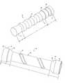
- FIG. 1is a perspective view of a stent according to one embodiment of the present invention.
- FIG. 2is an elevation view of the stent shown in FIG. 1 ;
- FIG. 3is a perspective view of a stent according to another embodiment of the present invention.
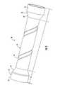
- FIG. 4is a perspective view of a stent according to another embodiment of the present invention.
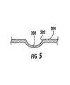
- FIG. 5is a cross-sectional view of a stabilization member according to one embodiment of the present invention.
- the stent 10includes a tubular member 12 having a plurality of stabilization members 14 defined circumferentially therein.
- the stent 10is positioned within the lumen adjacent to a target area, while the stabilization members 14 are configured to adapt to the muscular contractions of the esophagus thereby reducing migration of the stent 10 and the incidence of infolding of the tubular member 12 .
- the esophageal stent 10is capable of being deployed proximate to a target area within a lumen of the esophagus.
- Target areais not meant to limiting, as the target area, could be a stricture, lesion, tumor, fistulae, occlusion, or other complication where the lumen passageway has been significantly reduced or compromised.
- stentis also not meant to be limiting, as the stent could be any suitable implantable device capable of being deployed within a lumen and having stabilization members 14 , as described herein.
- the stentis applicable to a wide range of stenting applications.
- the stent 10could be used for stenting lumina of the duodenum, vascular lumina, or lumina of the biliary tract.
- the stent 10may include an interstice geometry including a scaffolding of struts.
- the strutsgenerally include a plurality of flexible interconnected legs and connectors.
- the stent 10may include a series of legs arranged circumferentially about the stent, as well as arranged in a series of rows along the longitudinal axis of the stent, while a plurality of connectors are arranged parallel to the longitudinal axis of the stent to connect the rows together.
- the stent 10could be a solid material with no interstice geometry if desired or indicated for a particular lumen.
- the stent 10could comprise a grid or mesh structure.
- the grid structureis typically fabricated from a tube pre-formed with depressions and provided with cut-outs using a laser.
- the remaining grid structureincludes webs with connections therebetween and having the flexibility and strength to impart a desired flexibility and strength.
- the strength of the stentcan be modified by altering the web width and/or increasing or decreasing the cut-outs.
- a mesh structureis typically woven using suitable wires.
- the meshes or honeycombscan be modified locally as required with a view to adapting the level of flexibility and/or strength to specific requirements.
- greater strengthwill be provided in the stent neighboring the target area to be bridged, such as by using an increased web width or a higher mesh density, as well as more tightly spaced stabilization members 14 , in the area of the stent proximate the target area.
- the stent 10is preferably formed from a material such as Ni, C, Co, Cu, Cr, H, Fe, Nb, O, SS, Ti and composites, alloys and combinations thereof (e.g., Nitinol), but could also be formed of polymeric materials.
- the materialis generally formed into a tube from which the stent is etched or laser cut and is formed on a suitable shaping device to give the stent the desired external geometry.
- the stent 10is typically formed of a memory material that facilitates flexibility of the stent region such that the stent may be deformed and return to its original shape. This flexibility allows the stent to be compressed radially for insertion into a stent delivery device, as discussed below, so as to self-expand when released into the lumen.
- stents in accordance with the present inventioncan take on various characteristic combinations of interstice geometry by changing angles, segment lengths, and segment thicknesses during the cutting and forming stages of stent engineering or during post-formation processing and polishing steps. Moreover, by modifying the geometry of the connectors, additional functionality may be achieved. In the event the stent 10 is to be shaped to the dimensions of a particular lumen, optical photography and/or optical videography of the target lumen may be conducted prior to stent formation. The interstice geometry of the stent 10 then can be etched and formed in accordance with the requirements of that lumen and/or target area.
- the stent 10may be coated or covered along its entire length or over portions of the tubular member, such as with polyurethane or silicone, in alternative aspects of the present invention.
- the stent 10could include a suture arranged about the proximal and/or distal ends of the tubular member 12 for repositioning or removing the stent. Spars, barbs, or the like may be incorporated into the geometry of the stent 10 at various locations, such as near the proximal and distal ends of the stent, in order to reduce migration following implantation within the lumen.
- stents 10could be incorporated and still be within the present scope of the invention as long as the configurations achieved are consistent with the geometry of the invention as described herein.
- An exemplary embodiment of the interstice geometry of a stent 10 of the present invention and methods of manufacturing the stentis disclosed in U.S. Patent Application Publication No. 20040127973, entitled “Removable Biliary Stent,” which is assigned to the present assignee and is incorporated herein by reference.
- the interstice geometry of the stent 10should not be limited to that described herein, as any number of configurations of interstice geometry could be employed with the present invention to achieve various degrees of rigidity and functionality.
- the stent 10is generally tubular, having openings at the proximal and distal ends, but could also have different geometrical forms, such as a horseshoe-shaped cross section suitable for tracheal stents.
- the proximal and distal ends of the tubular member 12include one or more end portions 16 (areas B and C).
- the diameter of the end portions 16can be slightly larger than the diameter of the core area A of the tubular member 12 extending therebetween so as to receive the target area and anchor the stent relative to the target area.
- the end portion 16 in area Bincludes a slightly conical flared tube segment, which adjoins a “valley” and slightly flares out towards its end.
- the end portion 16 defined by area Cincludes an essentially cylindrical segment, which adjoins the core area A at the level of a “peak” and is itself provided with a stabilization member 14 .
- the transitions of the depressions or “valleys” into the tubular member 12are provided with an additional bevel 18 to eliminate sharp edges.
- the bevels 18can generally be used rather than rounded edges.
- the end portion 16 at the proximal end of the tubular member 12may be shorter and slightly larger in diameter than the end portion at the distal end of the tubular member or vice versa.
- the end portions 16can be various sizes and configurations depending on the particular lumen or target area being stented.
- the end portions 16could be the same size and configuration if desired.
- the end portions 16could also be more or less flexible or strong than the tubular member 12 extending therebetween such as by utilizing different materials, reinforced materials, or materials that have been modified by a particular treatment.
- the flexibility and/or strength of the end portions 16could also be modified by leaving the end portions free from stabilization members 14 .
- FIG. 1demonstrates that there are a plurality of stabilization members 14 extending circumferentially about the tubular member 12 .
- Each of the stabilization members 14is generally configured as a ring that defines a concave or smaller diameter portion than the larger diameter portions of the tubular member 12 extending between each stabilization member.
- the core area Ais provided with a plurality of stabilization members 14 which, due to their rounded transitions with the tubular member 12 , lead to a more or less waved pattern.
- the “peaks” of the tubular member 12define the actual surface of the stent tube in the core area A.
- the configuration of the stabilization members 14defines an undulating or wavelike cross section substantially along the length of the tubular member 12 , where each portion extending between respective stabilization members is generally convex in cross section.
- the radius of the stabilization members 14 and the radial portions 11 of the tubular member extending between each stabilization memberare about the same such that there is a smooth transition between stabilization members.
- the stabilization members 14are typically defined integrally within the tubular member 12 and are approximately the same distance apart from one another.
- the stabilization members 14may include scaffolding, although the stabilization members could be a solid material having no interstice geometry if desired.
- the stabilization members 14 shown in FIG. 1may be various sizes and configurations to achieve desired properties for a particular lumen or target area and still be within the scope of the present invention.
- at least one stabilization member 14is defined within the core area A of the tubular member 12 .
- the stabilization members 14may not only be equidistantly spaced, but there may be a plurality of closely-spaced stabilization members 14 defined in the core area A of the tubular member 12 subject to loading (e.g., a target area), and widely-spaced stabilization members in other areas of the stent (areas B and C).
- the stabilization members 14can be various depths, cross sections, and widths, and may also extend at various angles about the tubular member.
- Each stabilization member 14could also be a different size and configuration than another stabilization member defined in the same tubular member 12 .
- the stabilization members 14may be parallel or non-parallel to each other.
- the stent 10is about 40-120 mm in length, and the stabilization members 14 are about 18-22 mm in diameter.
- the portions of the tubular member 12 extending between each stabilization member 14can also be various configurations rather than a convex curvature.
- the portions of the tubular member 12 between the stabilization members 14could be substantially cylindrical and have no curvature.
- the stent 50 shown in FIG. 3also includes a tubular member 52 , stabilization members 54 , and end portions 56 located at respective proximal and distal ends of the tubular member (areas B and C).
- the width and orientation of the stabilization members 54may vary substantially.
- the stabilization members 54are defined as turns of a helical groove (i.e., each turn corresponds to a stabilization member when taken in cross section along the longitudinal axis of the tubular member 52 ).
- the helical grooveincludes a plurality of turns extending radially and longitudinally about the tubular member 52 .
- FIG. 3illustrates a single helical groove including two turns such that each turn defines a stabilization member 54 .
- Each turnextends at an angle of about 60 degrees from the longitudinal axis of the tubular member 52 .
- the end portions 56generally include a conical section 60 adjacent to the core area A of the tubular member 52 , while the most proximal and distal portions of the tubular member include generally cylindrical sections 62 .
- the core area Ais generally cylindrical in configuration.
- the stabilization member 54may be various sizes and configurations depending on the particular characteristics of the stent 50 desired. For instance, there may be one or more helical grooves and/or turns for each helical groove. In addition, the helical grooves may be defined at various depths and locations within the tubular member 52 and extend at different angles radially about the tubular member.
- FIG. 4demonstrates an additional embodiment of the present invention, wherein stabilization members 104 are defined by a single helical groove having four turns. FIG. 4 also shows that the stabilization members 104 may be defined in the end portions 106 of the tubular member 102 .
- the helical groove of the stabilization members 104is narrower than that of the stabilization members 54 shown in FIG. 3 .
- the end portions 106 of the stent 100 depicted in FIG. 4extend at an angle outwardly from the core area A of the tubular member 102 .
- FIG. 5illustrates a cross-sectional view of a tubular member 204 with stabilization member 200 and rounded edges 202 according to one embodiment of the present invention.
- Rounded edges 202provide a curved transition between the stabilization member 200 and the adjacent tubular member 204 in order to reduce tissue injury during deployment of the stent within the lumen.
- Various techniquesmay be utilized to form the stabilization members 204 , such as mechanical imprinting or stamping. Due to the imprinting or stamping process employed to form the stabilization member 200 , the material is typically subjected to stretching, which leads to a reduction in wall thickness in the area of the stabilization member.
- the stabilization member 204is generally concave in configuration, such as a circular or semi-circular segment and can extend inwardly further than that shown in FIG. 5 .
- the inner and outer diameters of each stabilization member 200can be less than an inner diameter of the tubular member 204 , as shown in FIG. 5 .
- the stabilization member 200is typically a maximum of 10% of the diameter of the tubular member 204 , preferably about 2-8%, and more preferably about 5%.
- the depth of the stabilization member 200is dependent on the total diameter of the tubular member 204 , the loads expected to occur within the lumen, and/or the material of the stent.
- the esophageal stents 10 , 50 , and 100may be deployed within a lumen of the esophagus using various techniques.
- the esophageal stentis typically contracted to a smaller first diameter from a relaxed position. Once contracted, the esophageal stent is positioned within a delivery device, such as a catheter or tube that may be inserted within the lumen.
- the delivery devicecould be used to position and deploy the esophageal stent within the lumen. Examples of delivery devices suitable for implanting the esophageal stent are disclosed in U.S. patent application No. 60/680,556, entitled “Delivery Device with Shortened Inner Tube and Associated Method,” and U.S.
- Patent Application Publication No. 20040193243entitled “Medical Appliance Optical Delivery and Deployment Apparatus and Method,” both of which are assigned to the present assignee and incorporated herein by reference.
- techniques and devices known to those skilled in the art used to locate, contract, and/or remove the esophageal stent from the lumenmay be employed with the present invention.
- the esophageal stentis typically introduced orally with the delivery device, through the lumen, and proximate to a target area.
- the medial portion of the stentis positioned proximate to the target area such that when the esophageal stent is deployed from the catheter or tube, the stent, if formed from an expansible material, can expand to receive the target area and even expand the diameter of the target area.
- the stentcould open up the target area approximately 10-25 mm.
- the end portionswill be positioned proximally and distally of the target area and when deployed from the delivery device, will expand to contact the healthy tissue of the lumen and prevent migration.
- the stentis capable of dynamically expanding and retracting to closely mimic the motion of the lumen, which is beneficial for lumina such as the duodenum or esophagus where the lumen frequently changes size and position.
- the present inventionincludes several advantages.
- the esophageal stentis capable of opening up a target area within a lumen to restore the patient's ability to swallow.
- the stabilization ringsare configured such that forces applied through peristalsis is concentrated and distributed along the stabilization rings.
- the stabilization ringsreduce the incidence of infolding of the stent by providing flexibility when external forces are applied to side of the stent.
- the stabilization memberslimit the progression of deformations in the longitudinal direction, as the stabilization members act as internal barriers, which adds stability to the stent without adversely affecting the stent's functionality.
- the stentdecreases the incidence of occlusion of the stent openings without increasing the risk of damage to the wall of the esophageal lumen.
- the stabilization ringsare configured to reduce migration of the stent within the lumen.
- the stabilization membersmay not only provide a configuration for mimicking the motion of the lumen, but the concave curvature of the stabilization members may also promote tissue ingrowth therein to aid in fixating the stent within the lumen.
Landscapes
- Health & Medical Sciences (AREA)
- Gastroenterology & Hepatology (AREA)
- Pulmonology (AREA)
- Cardiology (AREA)
- Oral & Maxillofacial Surgery (AREA)
- Transplantation (AREA)
- Engineering & Computer Science (AREA)
- Biomedical Technology (AREA)
- Heart & Thoracic Surgery (AREA)
- Vascular Medicine (AREA)
- Life Sciences & Earth Sciences (AREA)
- Animal Behavior & Ethology (AREA)
- General Health & Medical Sciences (AREA)
- Public Health (AREA)
- Veterinary Medicine (AREA)
- Media Introduction/Drainage Providing Device (AREA)
- Prostheses (AREA)
Abstract
Description
Claims (24)
Applications Claiming Priority (2)
| Application Number | Priority Date | Filing Date | Title |
|---|---|---|---|
| DE102005019649ADE102005019649A1 (en) | 2005-04-26 | 2005-04-26 | Flexible stent for positioning in lumen of esophagus comprises tube and stabilization members defined circumferentially about tube, where each member extends inwardly in tube to define inner diameter that is less than inner diameter of tube |
| DE102005019649 | 2005-04-26 |
Publications (2)
| Publication Number | Publication Date |
|---|---|
| US20060259113A1 US20060259113A1 (en) | 2006-11-16 |
| US8834558B2true US8834558B2 (en) | 2014-09-16 |
Family
ID=36648664
Family Applications (1)
| Application Number | Title | Priority Date | Filing Date |
|---|---|---|---|
| US11/410,426Active2029-08-24US8834558B2 (en) | 2005-04-26 | 2006-04-25 | Esophageal stent and associated method |
Country Status (6)
| Country | Link |
|---|---|
| US (1) | US8834558B2 (en) |
| EP (1) | EP1887969B1 (en) |
| CA (1) | CA2606158A1 (en) |
| DE (1) | DE102005019649A1 (en) |
| PL (1) | PL1887969T3 (en) |
| WO (1) | WO2006116447A1 (en) |
Cited By (14)
| Publication number | Priority date | Publication date | Assignee | Title |
|---|---|---|---|---|
| US9700401B2 (en) | 2013-09-12 | 2017-07-11 | Boston Scientific Scimed, Inc. | Stent with anti-migration connectors |
| US10117763B2 (en) | 2014-03-18 | 2018-11-06 | Boston Scientific Scimed, Inc. | Reduced granulation and inflammation stent design |
| US10130498B2 (en) | 2014-10-22 | 2018-11-20 | Boston Scientific Scimed, Inc. | Stent with flexible hinge |
| US10219921B2 (en) | 2014-10-02 | 2019-03-05 | Boston Scientific Scimed, Inc. | Controlled ingrowth feature for antimigration |
| US10653510B2 (en) | 2016-11-09 | 2020-05-19 | Boston Scientific Scimed, Inc. | Stent including displacement capabilities |
| US10758380B2 (en) | 2016-12-30 | 2020-09-01 | Bvw Holding Ag | Stents with improved fixation |
| US10898354B2 (en) | 2014-11-06 | 2021-01-26 | Boston Scientific Scimed, Inc. | Tracheal stent |
| WO2022020633A1 (en)* | 2020-07-24 | 2022-01-27 | Merit Medical Systems, Inc. | Esophageal stents and related methods |
| US11707370B2 (en) | 2017-03-15 | 2023-07-25 | Merit Medical Systems, Inc. | Stents and related methods |
| US11707368B2 (en) | 2020-02-03 | 2023-07-25 | Boston Scientific Scimed, Inc. | Stent, mandrel, and method for forming a stent with anti-migration features |
| US11759341B2 (en) | 2020-01-13 | 2023-09-19 | Boston Scientific Scimed, Inc. | Anti-migration stent |
| US11786355B2 (en) | 2020-01-30 | 2023-10-17 | Boston Scientific Scimed, Inc. | Radial adjusting self-expanding stent with anti-migration features |
| US11963893B2 (en) | 2020-10-26 | 2024-04-23 | Merit Medical Systems, Inc. | Esophageal stents with helical thread |
| US12274634B2 (en) | 2016-09-29 | 2025-04-15 | Merit Medical Systems, Inc. | Pliant members for receiving and aiding in the deployment of vascular prostheses |
Families Citing this family (9)
| Publication number | Priority date | Publication date | Assignee | Title |
|---|---|---|---|---|
| WO2011136963A1 (en)* | 2010-04-30 | 2011-11-03 | Boston Scientific Scimed, Inc. | Duodenal metabolic stent |
| JP4991014B2 (en)* | 2010-07-07 | 2012-08-01 | 日機装株式会社 | Artificial blood vessel |
| US20130110221A1 (en)* | 2011-10-27 | 2013-05-02 | Triona Campbell | Stent with Inwardly-Directed Protrusion |
| US20130197657A1 (en)* | 2011-12-08 | 2013-08-01 | Diana Anca | Central airway stent |
| CN104095696B (en)* | 2013-04-08 | 2016-06-29 | 上海市同济医院 | For the stent in esophagus that ER and anastomotic leakage block |
| AU2015277089B2 (en)* | 2014-06-18 | 2017-11-02 | Boston Scientific Scimed, Inc. | Biliary stent |
| KR101628711B1 (en)* | 2014-06-26 | 2016-06-09 | 주식회사 에스앤지바이오텍 | Stent With External Flow Path |
| US20180360627A1 (en)* | 2017-06-19 | 2018-12-20 | Cook Medical Technologies Llc | Stent with helical groove |
| KR102213245B1 (en)* | 2019-07-19 | 2021-02-05 | 울산대학교 산학협력단 | Stent for airway |
Citations (71)
| Publication number | Priority date | Publication date | Assignee | Title |
|---|---|---|---|---|
| US3044497A (en) | 1944-05-11 | 1962-07-17 | Bodin Girin & Cie Soc | Tubular members provided with corrugated walls |
| US4164045A (en)* | 1977-08-03 | 1979-08-14 | Carbomedics, Inc. | Artificial vascular and patch grafts |
| GB2069339A (en) | 1980-02-18 | 1981-08-26 | Keymed Medicals & Ind Equip | Endo-oesophageal tube |
| US4313231A (en)* | 1980-06-16 | 1982-02-02 | Kabushiki Kaisha Tatebe Seishudo | Vascular prosthesis |
| WO1990004982A1 (en) | 1988-11-10 | 1990-05-17 | Biocon Oy | Biodegradable surgical implants and devices |
| US5129910A (en) | 1991-07-26 | 1992-07-14 | The Regents Of The University Of California | Stone expulsion stent |
| US5282847A (en)* | 1991-02-28 | 1994-02-01 | Medtronic, Inc. | Prosthetic vascular grafts with a pleated structure |
| WO1994012136A1 (en) | 1992-10-13 | 1994-06-09 | Boston Scientific Corporation | Stents for body lumens exhibiting peristaltic |
| US5330500A (en) | 1990-10-18 | 1994-07-19 | Song Ho Y | Self-expanding endovascular stent with silicone coating |
| EP0666066A1 (en) | 1994-02-08 | 1995-08-09 | Ethicon, Inc. | Bi-directional crimped graft |
| DE29708879U1 (en) | 1997-05-20 | 1997-07-31 | Jomed Implantate GmbH, 72414 Rangendingen | Coronary stent |
| US5662713A (en)* | 1991-10-09 | 1997-09-02 | Boston Scientific Corporation | Medical stents for body lumens exhibiting peristaltic motion |
| DE69126428T2 (en) | 1990-04-19 | 1997-10-30 | Instent Inc | DEVICE FOR TREATING NARROW VESSELS |
| US5723003A (en)* | 1994-09-13 | 1998-03-03 | Ultrasonic Sensing And Monitoring Systems | Expandable graft assembly and method of use |
| US5866217A (en)* | 1991-11-04 | 1999-02-02 | Possis Medical, Inc. | Silicone composite vascular graft |
| US5876448A (en) | 1992-05-08 | 1999-03-02 | Schneider (Usa) Inc. | Esophageal stent |
| DE19754747A1 (en) | 1997-12-10 | 1999-06-17 | Impag Gmbh Medizintechnik | Device for being implanted into hollow space of human body in particular into gullet |
| WO1999049810A1 (en) | 1998-03-27 | 1999-10-07 | Intratherapeutics, Inc. | Stent |
| US6001123A (en)* | 1994-04-01 | 1999-12-14 | Gore Enterprise Holdings Inc. | Folding self-expandable intravascular stent-graft |
| US6106548A (en) | 1997-02-07 | 2000-08-22 | Endosystems Llc | Non-foreshortening intraluminal prosthesis |
| US6176873B1 (en) | 1997-06-25 | 2001-01-23 | Asahi Kogaku Kogyo Kabushiki Kaisha | Stent for endoscope |
| US6224626B1 (en) | 1998-02-17 | 2001-05-01 | Md3, Inc. | Ultra-thin expandable stent |
| DE19949334A1 (en) | 1999-10-13 | 2001-05-23 | Jostra Ag | Colon stent |
| US6248058B1 (en) | 1998-12-11 | 2001-06-19 | Enteric Medical Technologies, Inc. | Method for treating tracheo-esophageal fistulas |
| US6273909B1 (en)* | 1998-10-05 | 2001-08-14 | Teramed Inc. | Endovascular graft system |
| WO2001058384A1 (en) | 2000-02-14 | 2001-08-16 | Angiomed Gmbh & Co. Medizintechnik Kg | Stent matrix |
| WO2001072239A2 (en) | 2000-03-27 | 2001-10-04 | Neovasc (2002) Ltd. | Narrowing implant |
| US20010027341A1 (en)* | 1997-07-17 | 2001-10-04 | Marc Gianotti | Stents with elevations at selected crossing points |
| US6302917B1 (en) | 1998-08-31 | 2001-10-16 | Wilson-Cook Medical Incorporated | Anti-reflux esophageal prosthesis |
| WO2001089419A1 (en) | 2000-05-19 | 2001-11-29 | C.R. Bard, Inc. | Stents and stenting methods |
| US6325825B1 (en) | 1999-04-08 | 2001-12-04 | Cordis Corporation | Stent with variable wall thickness |
| US6358275B1 (en)* | 1999-10-04 | 2002-03-19 | Sulzer Carbomedics Inc. | Tissue-derived vascular grafts and methods for making the same |
| US20020062148A1 (en)* | 1997-02-26 | 2002-05-23 | Charles C. Hart | Kinetic stent |
| US6416545B1 (en) | 1996-04-09 | 2002-07-09 | Endocare, Inc. | Urological stent therapy system and method |
| US6425915B1 (en) | 1997-03-18 | 2002-07-30 | Endotex Interventional Systems, Inc. | Helical mesh endoprosthesis and methods of use |
| WO2002069848A2 (en) | 2001-03-06 | 2002-09-12 | Board Of Regents, The University Of Texas System | Apparatus for stent deployment with delivery of bioactive agents |
| US6475232B1 (en) | 1996-12-10 | 2002-11-05 | Purdue Research Foundation | Stent with reduced thrombogenicity |
| US6494908B1 (en) | 1999-12-22 | 2002-12-17 | Ethicon, Inc. | Removable stent for body lumens |
| US20030024534A1 (en)* | 2001-07-26 | 2003-02-06 | Silvestri Gerard A. | Removable stent and method of using the same |
| US20030040803A1 (en) | 2001-08-23 | 2003-02-27 | Rioux Robert F. | Maintaining an open passageway through a body lumen |
| US20030072868A1 (en) | 2000-12-28 | 2003-04-17 | Sameer Harish | Methods of forming a coating for a prosthesis |
| US6589213B2 (en) | 1997-12-12 | 2003-07-08 | Wilson-Cook Medical Incorporated | Body canal intrusion instrumentation having bi-directional coefficient of surface friction with body tissue |
| US20030130611A1 (en) | 2002-01-07 | 2003-07-10 | Martin Eric C. | Two-piece stent combination for percutaneous arterialization of the coronary sinus and retrograde perfusion of the myocardium |
| US20030139799A1 (en)* | 2002-01-23 | 2003-07-24 | Ley Timothy J. | Multi-layer stent |
| US20030176831A1 (en)* | 2002-03-18 | 2003-09-18 | Gellman Barry N. | Expandable ureteral stent |
| US20030199989A1 (en)* | 2001-08-27 | 2003-10-23 | Stack Richard S. | Satiation devices and methods |
| US20030212450A1 (en) | 2002-05-11 | 2003-11-13 | Tilman Schlick | Stent |
| US6652573B2 (en) | 1998-05-16 | 2003-11-25 | Jomed Gmbh | Radial expansible stent for implanting in body vessels |
| US20040015228A1 (en)* | 2000-08-17 | 2004-01-22 | Sylvie Lombardi | Implant with attached element and method of making such an implant |
| US20040049264A1 (en)* | 2002-09-06 | 2004-03-11 | Scimed Life Systems, Inc. | ePTFE crimped graft |
| US20040102833A1 (en)* | 2002-11-27 | 2004-05-27 | Scimed Life Systems, Inc. | Expandable stents |
| US20040102855A1 (en)* | 2002-11-21 | 2004-05-27 | Scimed Life Systems, Inc. | Anti-reflux stent |
| US6746489B2 (en) | 1998-08-31 | 2004-06-08 | Wilson-Cook Medical Incorporated | Prosthesis having a sleeve valve |
| US20040182511A1 (en)* | 2001-06-11 | 2004-09-23 | Scimed Life Systems, Inc. | Pressure lamination method for forming composite ePTFE/textile and ePTFE/stent/textile prostheses |
| US20040193283A1 (en) | 2003-03-26 | 2004-09-30 | Scimed Life Systems, Inc. | Longitudinally expanding medical device |
| EP0836450B1 (en) | 1995-06-13 | 2004-11-10 | WILLIAM COOK EUROPE ApS | A device for implantation in a vessel or hollow organ lumen |
| WO2004096097A2 (en) | 2003-04-25 | 2004-11-11 | Boston Scientific Limited | Cutting stent and balloon |
| US6818015B2 (en) | 1995-11-27 | 2004-11-16 | Schneider (Europe) Gmbh | Conical stent |
| WO2004100827A2 (en) | 2003-05-07 | 2004-11-25 | Advanced Bio Prosthetic Surfaces, Ltd. | Metallic implantable grafts and method of making same |
| US20050010275A1 (en) | 2002-10-11 | 2005-01-13 | Sahatjian Ronald A. | Implantable medical devices |
| WO2005011527A1 (en) | 2003-07-30 | 2005-02-10 | Jotec Gmbh | Woven stent to be implanted in a blood vessel |
| US20050055039A1 (en)* | 2003-07-28 | 2005-03-10 | Polymorfix, Inc. | Devices and methods for pyloric anchoring |
| US20050060023A1 (en)* | 1999-03-18 | 2005-03-17 | Fossa Medical, Inc. | Radially expandable stents |
| US20050075715A1 (en) | 2003-10-07 | 2005-04-07 | Juan Borges | Graft material attachment device and method |
| US6911041B1 (en)* | 1997-10-23 | 2005-06-28 | C. R. Bard, Inc. | Expanded stent and a method for producing same |
| US20050143805A1 (en) | 2003-10-28 | 2005-06-30 | Helmut Hierlemann | Tubular implant |
| US20060047334A1 (en)* | 2002-06-05 | 2006-03-02 | Tayside Flow Technologies Limited | Method of determining the helix angle of a helical formation for a conduit |
| US20060106455A1 (en)* | 2004-11-12 | 2006-05-18 | Icon Interventional Systems, Inc. | Ostial stent |
| US7060092B2 (en)* | 2001-03-29 | 2006-06-13 | Isis Innovation Limited | Deployable stent |
| US20060129232A1 (en)* | 2004-12-10 | 2006-06-15 | Dicarlo Paul | Implantable medical devices, and methods of delivering the same |
| US7575591B2 (en)* | 2003-12-01 | 2009-08-18 | Cordis Corporation | Prosthesis graft with Z pleating |
Family Cites Families (2)
| Publication number | Priority date | Publication date | Assignee | Title |
|---|---|---|---|---|
| US530500A (en)* | 1894-12-11 | Machine for jointing listed staves | ||
| FR1103165A (en)* | 1954-06-25 | 1955-10-31 | Device for the treatment of stenosis of the esophagus |
- 2005
- 2005-04-26DEDE102005019649Apatent/DE102005019649A1/ennot_activeWithdrawn
- 2006
- 2006-04-25EPEP06751421.6Apatent/EP1887969B1/enactiveActive
- 2006-04-25PLPL06751421Tpatent/PL1887969T3/enunknown
- 2006-04-25USUS11/410,426patent/US8834558B2/enactiveActive
- 2006-04-25WOPCT/US2006/015719patent/WO2006116447A1/enactiveApplication Filing
- 2006-04-25CACA002606158Apatent/CA2606158A1/ennot_activeAbandoned
Patent Citations (79)
| Publication number | Priority date | Publication date | Assignee | Title |
|---|---|---|---|---|
| US3044497A (en) | 1944-05-11 | 1962-07-17 | Bodin Girin & Cie Soc | Tubular members provided with corrugated walls |
| US4164045A (en)* | 1977-08-03 | 1979-08-14 | Carbomedics, Inc. | Artificial vascular and patch grafts |
| GB2069339A (en) | 1980-02-18 | 1981-08-26 | Keymed Medicals & Ind Equip | Endo-oesophageal tube |
| US4313231A (en)* | 1980-06-16 | 1982-02-02 | Kabushiki Kaisha Tatebe Seishudo | Vascular prosthesis |
| WO1990004982A1 (en) | 1988-11-10 | 1990-05-17 | Biocon Oy | Biodegradable surgical implants and devices |
| DE69126428T2 (en) | 1990-04-19 | 1997-10-30 | Instent Inc | DEVICE FOR TREATING NARROW VESSELS |
| US5330500A (en) | 1990-10-18 | 1994-07-19 | Song Ho Y | Self-expanding endovascular stent with silicone coating |
| US5282847A (en)* | 1991-02-28 | 1994-02-01 | Medtronic, Inc. | Prosthetic vascular grafts with a pleated structure |
| US5129910A (en) | 1991-07-26 | 1992-07-14 | The Regents Of The University Of California | Stone expulsion stent |
| US5662713A (en)* | 1991-10-09 | 1997-09-02 | Boston Scientific Corporation | Medical stents for body lumens exhibiting peristaltic motion |
| US6505654B1 (en) | 1991-10-09 | 2003-01-14 | Scimed Life Systems, Inc. | Medical stents for body lumens exhibiting peristaltic motion |
| US6146416A (en) | 1991-10-09 | 2000-11-14 | Boston Scientific Corporation | Medical stents for body lumens exhibiting peristaltic motion |
| US5866217A (en)* | 1991-11-04 | 1999-02-02 | Possis Medical, Inc. | Silicone composite vascular graft |
| DE69333161T2 (en) | 1992-05-08 | 2004-06-03 | Schneider (Usa) Inc., Plymouth | Stent for the esophagus |
| US5876448A (en) | 1992-05-08 | 1999-03-02 | Schneider (Usa) Inc. | Esophageal stent |
| WO1994012136A1 (en) | 1992-10-13 | 1994-06-09 | Boston Scientific Corporation | Stents for body lumens exhibiting peristaltic |
| EP0666066A1 (en) | 1994-02-08 | 1995-08-09 | Ethicon, Inc. | Bi-directional crimped graft |
| US5476506A (en)* | 1994-02-08 | 1995-12-19 | Ethicon, Inc. | Bi-directional crimped graft |
| US6001123A (en)* | 1994-04-01 | 1999-12-14 | Gore Enterprise Holdings Inc. | Folding self-expandable intravascular stent-graft |
| US5723003A (en)* | 1994-09-13 | 1998-03-03 | Ultrasonic Sensing And Monitoring Systems | Expandable graft assembly and method of use |
| EP0836450B1 (en) | 1995-06-13 | 2004-11-10 | WILLIAM COOK EUROPE ApS | A device for implantation in a vessel or hollow organ lumen |
| US6818015B2 (en) | 1995-11-27 | 2004-11-16 | Schneider (Europe) Gmbh | Conical stent |
| US6416545B1 (en) | 1996-04-09 | 2002-07-09 | Endocare, Inc. | Urological stent therapy system and method |
| US6475232B1 (en) | 1996-12-10 | 2002-11-05 | Purdue Research Foundation | Stent with reduced thrombogenicity |
| US6106548A (en) | 1997-02-07 | 2000-08-22 | Endosystems Llc | Non-foreshortening intraluminal prosthesis |
| US20020062148A1 (en)* | 1997-02-26 | 2002-05-23 | Charles C. Hart | Kinetic stent |
| US6425915B1 (en) | 1997-03-18 | 2002-07-30 | Endotex Interventional Systems, Inc. | Helical mesh endoprosthesis and methods of use |
| US6017365A (en) | 1997-05-20 | 2000-01-25 | Jomed Implantate Gmbh | Coronary stent |
| DE29708879U1 (en) | 1997-05-20 | 1997-07-31 | Jomed Implantate GmbH, 72414 Rangendingen | Coronary stent |
| US6176873B1 (en) | 1997-06-25 | 2001-01-23 | Asahi Kogaku Kogyo Kabushiki Kaisha | Stent for endoscope |
| US20010027341A1 (en)* | 1997-07-17 | 2001-10-04 | Marc Gianotti | Stents with elevations at selected crossing points |
| US6911041B1 (en)* | 1997-10-23 | 2005-06-28 | C. R. Bard, Inc. | Expanded stent and a method for producing same |
| DE19754747A1 (en) | 1997-12-10 | 1999-06-17 | Impag Gmbh Medizintechnik | Device for being implanted into hollow space of human body in particular into gullet |
| US6589213B2 (en) | 1997-12-12 | 2003-07-08 | Wilson-Cook Medical Incorporated | Body canal intrusion instrumentation having bi-directional coefficient of surface friction with body tissue |
| US6224626B1 (en) | 1998-02-17 | 2001-05-01 | Md3, Inc. | Ultra-thin expandable stent |
| WO1999049810A1 (en) | 1998-03-27 | 1999-10-07 | Intratherapeutics, Inc. | Stent |
| US6652573B2 (en) | 1998-05-16 | 2003-11-25 | Jomed Gmbh | Radial expansible stent for implanting in body vessels |
| US6302917B1 (en) | 1998-08-31 | 2001-10-16 | Wilson-Cook Medical Incorporated | Anti-reflux esophageal prosthesis |
| US6746489B2 (en) | 1998-08-31 | 2004-06-08 | Wilson-Cook Medical Incorporated | Prosthesis having a sleeve valve |
| US6273909B1 (en)* | 1998-10-05 | 2001-08-14 | Teramed Inc. | Endovascular graft system |
| US6248058B1 (en) | 1998-12-11 | 2001-06-19 | Enteric Medical Technologies, Inc. | Method for treating tracheo-esophageal fistulas |
| US20050060023A1 (en)* | 1999-03-18 | 2005-03-17 | Fossa Medical, Inc. | Radially expandable stents |
| US6325825B1 (en) | 1999-04-08 | 2001-12-04 | Cordis Corporation | Stent with variable wall thickness |
| US6358275B1 (en)* | 1999-10-04 | 2002-03-19 | Sulzer Carbomedics Inc. | Tissue-derived vascular grafts and methods for making the same |
| DE19949334A1 (en) | 1999-10-13 | 2001-05-23 | Jostra Ag | Colon stent |
| US6494908B1 (en) | 1999-12-22 | 2002-12-17 | Ethicon, Inc. | Removable stent for body lumens |
| WO2001058384A1 (en) | 2000-02-14 | 2001-08-16 | Angiomed Gmbh & Co. Medizintechnik Kg | Stent matrix |
| WO2001072239A2 (en) | 2000-03-27 | 2001-10-04 | Neovasc (2002) Ltd. | Narrowing implant |
| WO2001089419A1 (en) | 2000-05-19 | 2001-11-29 | C.R. Bard, Inc. | Stents and stenting methods |
| US20040015228A1 (en)* | 2000-08-17 | 2004-01-22 | Sylvie Lombardi | Implant with attached element and method of making such an implant |
| US20030072868A1 (en) | 2000-12-28 | 2003-04-17 | Sameer Harish | Methods of forming a coating for a prosthesis |
| WO2002069848A2 (en) | 2001-03-06 | 2002-09-12 | Board Of Regents, The University Of Texas System | Apparatus for stent deployment with delivery of bioactive agents |
| US7060092B2 (en)* | 2001-03-29 | 2006-06-13 | Isis Innovation Limited | Deployable stent |
| US20040182511A1 (en)* | 2001-06-11 | 2004-09-23 | Scimed Life Systems, Inc. | Pressure lamination method for forming composite ePTFE/textile and ePTFE/stent/textile prostheses |
| US20030024534A1 (en)* | 2001-07-26 | 2003-02-06 | Silvestri Gerard A. | Removable stent and method of using the same |
| US20030040803A1 (en) | 2001-08-23 | 2003-02-27 | Rioux Robert F. | Maintaining an open passageway through a body lumen |
| US20030199989A1 (en)* | 2001-08-27 | 2003-10-23 | Stack Richard S. | Satiation devices and methods |
| US6675809B2 (en) | 2001-08-27 | 2004-01-13 | Richard S. Stack | Satiation devices and methods |
| US20030130611A1 (en) | 2002-01-07 | 2003-07-10 | Martin Eric C. | Two-piece stent combination for percutaneous arterialization of the coronary sinus and retrograde perfusion of the myocardium |
| US20030139799A1 (en)* | 2002-01-23 | 2003-07-24 | Ley Timothy J. | Multi-layer stent |
| US20030176831A1 (en)* | 2002-03-18 | 2003-09-18 | Gellman Barry N. | Expandable ureteral stent |
| US20030212450A1 (en) | 2002-05-11 | 2003-11-13 | Tilman Schlick | Stent |
| US20060047334A1 (en)* | 2002-06-05 | 2006-03-02 | Tayside Flow Technologies Limited | Method of determining the helix angle of a helical formation for a conduit |
| US20040049264A1 (en)* | 2002-09-06 | 2004-03-11 | Scimed Life Systems, Inc. | ePTFE crimped graft |
| US20050010275A1 (en) | 2002-10-11 | 2005-01-13 | Sahatjian Ronald A. | Implantable medical devices |
| US20040102855A1 (en)* | 2002-11-21 | 2004-05-27 | Scimed Life Systems, Inc. | Anti-reflux stent |
| US20040102833A1 (en)* | 2002-11-27 | 2004-05-27 | Scimed Life Systems, Inc. | Expandable stents |
| US20040193283A1 (en) | 2003-03-26 | 2004-09-30 | Scimed Life Systems, Inc. | Longitudinally expanding medical device |
| WO2004096097A2 (en) | 2003-04-25 | 2004-11-11 | Boston Scientific Limited | Cutting stent and balloon |
| WO2004100827A2 (en) | 2003-05-07 | 2004-11-25 | Advanced Bio Prosthetic Surfaces, Ltd. | Metallic implantable grafts and method of making same |
| US20050033418A1 (en)* | 2003-05-07 | 2005-02-10 | Banas Christopher E. | Metallic implantable grafts and method of making same |
| US20050055039A1 (en)* | 2003-07-28 | 2005-03-10 | Polymorfix, Inc. | Devices and methods for pyloric anchoring |
| WO2005011527A1 (en) | 2003-07-30 | 2005-02-10 | Jotec Gmbh | Woven stent to be implanted in a blood vessel |
| US20050075715A1 (en) | 2003-10-07 | 2005-04-07 | Juan Borges | Graft material attachment device and method |
| US20050143805A1 (en) | 2003-10-28 | 2005-06-30 | Helmut Hierlemann | Tubular implant |
| US7575591B2 (en)* | 2003-12-01 | 2009-08-18 | Cordis Corporation | Prosthesis graft with Z pleating |
| US20060106455A1 (en)* | 2004-11-12 | 2006-05-18 | Icon Interventional Systems, Inc. | Ostial stent |
| US20080275541A1 (en)* | 2004-11-12 | 2008-11-06 | Icon Interventional Systems, Inc. | Ostial stent |
| US20060129232A1 (en)* | 2004-12-10 | 2006-06-15 | Dicarlo Paul | Implantable medical devices, and methods of delivering the same |
Non-Patent Citations (6)
| Title |
|---|
| European Examination Report dated Mar. 25, 2014 for EP06751421.6. |
| PCT Notification of Transmittal of the International Search Report and the Written Opinion of the International Searching Authority, or the Declaration, mailed Jul. 25, 2006 for PCT/US2006/015719 (Filed Apr. 25, 2006). |
| Polyflex® Esophageal Stent, Boston Scientific, 2 pages, available at http://wwwbostonscientific.com/med-specialty/deviceDetail.jhtml?task=tskBasicDevice.jht; Downloaded on May 19, 2005. Examiner. |
| Polyflex® Esophageal Stent, Boston Scientific, 2 pages, available at http://wwwbostonscientific.com/med—specialty/deviceDetail.jhtml?task=tskBasicDevice.jht; Downloaded on May 19, 2005. Examiner. |
| Ultraflex(TM)Esophageal NG Stent System, Boston Scientific; 2 pages, available at http://www.bostonscientific.com/med-specialty/deviceDetail.jsp?task=tskBasicDevice.jsp; Downloaded on May 19, 2005. |
| Ultraflex™Esophageal NG Stent System, Boston Scientific; 2 pages, available at http://www.bostonscientific.com/med—specialty/deviceDetail.jsp?task=tskBasicDevice.jsp; Downloaded on May 19, 2005. |
Cited By (18)
| Publication number | Priority date | Publication date | Assignee | Title |
|---|---|---|---|---|
| US9700401B2 (en) | 2013-09-12 | 2017-07-11 | Boston Scientific Scimed, Inc. | Stent with anti-migration connectors |
| US10117763B2 (en) | 2014-03-18 | 2018-11-06 | Boston Scientific Scimed, Inc. | Reduced granulation and inflammation stent design |
| US11590008B2 (en) | 2014-10-02 | 2023-02-28 | Boston Scientific Scimed, Inc. | Controlled ingrowth feature for antimigration |
| US10219921B2 (en) | 2014-10-02 | 2019-03-05 | Boston Scientific Scimed, Inc. | Controlled ingrowth feature for antimigration |
| US10130498B2 (en) | 2014-10-22 | 2018-11-20 | Boston Scientific Scimed, Inc. | Stent with flexible hinge |
| US10898354B2 (en) | 2014-11-06 | 2021-01-26 | Boston Scientific Scimed, Inc. | Tracheal stent |
| US12274634B2 (en) | 2016-09-29 | 2025-04-15 | Merit Medical Systems, Inc. | Pliant members for receiving and aiding in the deployment of vascular prostheses |
| US10653510B2 (en) | 2016-11-09 | 2020-05-19 | Boston Scientific Scimed, Inc. | Stent including displacement capabilities |
| US10758380B2 (en) | 2016-12-30 | 2020-09-01 | Bvw Holding Ag | Stents with improved fixation |
| US11707370B2 (en) | 2017-03-15 | 2023-07-25 | Merit Medical Systems, Inc. | Stents and related methods |
| US11759341B2 (en) | 2020-01-13 | 2023-09-19 | Boston Scientific Scimed, Inc. | Anti-migration stent |
| US11786355B2 (en) | 2020-01-30 | 2023-10-17 | Boston Scientific Scimed, Inc. | Radial adjusting self-expanding stent with anti-migration features |
| US12364589B2 (en) | 2020-01-30 | 2025-07-22 | Boston Scientific Scimed, Inc. | Radial adjusting self-expanding stent with anti-migration features |
| US11707368B2 (en) | 2020-02-03 | 2023-07-25 | Boston Scientific Scimed, Inc. | Stent, mandrel, and method for forming a stent with anti-migration features |
| US12433774B2 (en) | 2020-02-03 | 2025-10-07 | Boston Scientific Scimed, Inc. | Stent, mandrel, and method for forming a stent with anti-migration features |
| WO2022020633A1 (en)* | 2020-07-24 | 2022-01-27 | Merit Medical Systems, Inc. | Esophageal stents and related methods |
| US12090038B2 (en) | 2020-07-24 | 2024-09-17 | Merit Medical Systems , Inc. | Esophageal stents and related methods |
| US11963893B2 (en) | 2020-10-26 | 2024-04-23 | Merit Medical Systems, Inc. | Esophageal stents with helical thread |
Also Published As
| Publication number | Publication date |
|---|---|
| WO2006116447A1 (en) | 2006-11-02 |
| US20060259113A1 (en) | 2006-11-16 |
| EP1887969A1 (en) | 2008-02-20 |
| PL1887969T3 (en) | 2018-01-31 |
| DE102005019649A1 (en) | 2006-11-02 |
| EP1887969B1 (en) | 2017-09-06 |
| CA2606158A1 (en) | 2006-11-02 |
Similar Documents
| Publication | Publication Date | Title |
|---|---|---|
| US8834558B2 (en) | Esophageal stent and associated method | |
| US8323350B2 (en) | Duodenum stent and associated method | |
| US20230277294A1 (en) | Device for anastomotic bypass | |
| US9585778B2 (en) | Segmented scaffold designs | |
| US8425586B2 (en) | Vascular prosthesis with stress relief slots | |
| US20180193175A1 (en) | Stents with improved fixation | |
| CN102413791B (en) | flexible device | |
| US20190167459A1 (en) | Endoprosthesis delivery system with improved retraction | |
| US12064333B2 (en) | Stent with atraumatic spacer | |
| US20230233346A1 (en) | Stent with multiple knitting patterns |
Legal Events
| Date | Code | Title | Description |
|---|---|---|---|
| AS | Assignment | Owner name:ALVEOLUS, INC., NORTH CAROLINA Free format text:ASSIGNMENT OF ASSIGNORS INTEREST;ASSIGNOR:NISSL, THOMAS;REEL/FRAME:017920/0609 Effective date:20060629 | |
| AS | Assignment | Owner name:MERIT MEDICAL SYSTEMS, INC., UTAH Free format text:ASSIGNMENT OF ASSIGNORS INTEREST;ASSIGNOR:ALVEOLUS, INC.;REEL/FRAME:022664/0727 Effective date:20090310 | |
| AS | Assignment | Owner name:WELLS FARGO BANK, NATIONAL ASSOCIATION, AS ADMINIS Free format text:PATENT SECURITY AGREEMENT;ASSIGNOR:MERIT MEDICAL SYSTEMS, INC.;REEL/FRAME:029698/0033 Effective date:20121219 Owner name:WELLS FARGO BANK, NATIONAL ASSOCIATION, AS ADMINISTRATIVE AGENT, UTAH Free format text:PATENT SECURITY AGREEMENT;ASSIGNOR:MERIT MEDICAL SYSTEMS, INC.;REEL/FRAME:029698/0033 Effective date:20121219 | |
| STCF | Information on status: patent grant | Free format text:PATENTED CASE | |
| MAFP | Maintenance fee payment | Free format text:PAYMENT OF MAINTENANCE FEE, 4TH YEAR, LARGE ENTITY (ORIGINAL EVENT CODE: M1551) Year of fee payment:4 | |
| MAFP | Maintenance fee payment | Free format text:PAYMENT OF MAINTENANCE FEE, 8TH YEAR, LARGE ENTITY (ORIGINAL EVENT CODE: M1552); ENTITY STATUS OF PATENT OWNER: LARGE ENTITY Year of fee payment:8 |