US8834540B2 - Polyaxial bone screw with lateral connector - Google Patents
Polyaxial bone screw with lateral connectorDownload PDFInfo
- Publication number
- US8834540B2 US8834540B2US13/277,439US201113277439AUS8834540B2US 8834540 B2US8834540 B2US 8834540B2US 201113277439 AUS201113277439 AUS 201113277439AUS 8834540 B2US8834540 B2US 8834540B2
- Authority
- US
- United States
- Prior art keywords
- side wall
- lateral connector
- lumen
- body member
- orientations
- Prior art date
- Legal status (The legal status is an assumption and is not a legal conclusion. Google has not performed a legal analysis and makes no representation as to the accuracy of the status listed.)
- Active
Links
- 210000000988bone and boneAnatomy0.000titledescription3
- 230000006641stabilisationEffects0.000description7
- 238000011105stabilizationMethods0.000description7
- 238000000034methodMethods0.000description4
- 239000000463materialSubstances0.000description3
- 238000005266castingMethods0.000description2
- 210000001503jointAnatomy0.000description2
- 238000003754machiningMethods0.000description2
- 238000004519manufacturing processMethods0.000description2
- 238000012986modificationMethods0.000description2
- 230000004048modificationEffects0.000description2
- 229910001220stainless steelInorganic materials0.000description2
- 239000010935stainless steelSubstances0.000description2
- 208000003618Intervertebral Disc DisplacementDiseases0.000description1
- 206010050296Intervertebral disc protrusionDiseases0.000description1
- RTAQQCXQSZGOHL-UHFFFAOYSA-NTitaniumChemical compound[Ti]RTAQQCXQSZGOHL-UHFFFAOYSA-N0.000description1
- 230000003247decreasing effectEffects0.000description1
- 230000004927fusionEffects0.000description1
- 210000003692iliumAnatomy0.000description1
- 238000002513implantationMethods0.000description1
- 230000002401inhibitory effectEffects0.000description1
- 230000007246mechanismEffects0.000description1
- 239000002184metalSubstances0.000description1
- 229910052751metalInorganic materials0.000description1
- 239000007769metal materialSubstances0.000description1
- 150000002739metalsChemical class0.000description1
- HLXZNVUGXRDIFK-UHFFFAOYSA-Nnickel titaniumChemical compound[Ti].[Ti].[Ti].[Ti].[Ti].[Ti].[Ti].[Ti].[Ti].[Ti].[Ti].[Ni].[Ni].[Ni].[Ni].[Ni].[Ni].[Ni].[Ni].[Ni].[Ni].[Ni].[Ni].[Ni].[Ni]HLXZNVUGXRDIFK-UHFFFAOYSA-N0.000description1
- 229910001000nickel titaniumInorganic materials0.000description1
- 239000007787solidSubstances0.000description1
- 238000001228spectrumMethods0.000description1
- 229920002994synthetic fiberPolymers0.000description1
- 210000001519tissueAnatomy0.000description1
- 239000010936titaniumSubstances0.000description1
- 229910052719titaniumInorganic materials0.000description1
Images


Classifications
- A—HUMAN NECESSITIES
- A61—MEDICAL OR VETERINARY SCIENCE; HYGIENE
- A61B—DIAGNOSIS; SURGERY; IDENTIFICATION
- A61B17/00—Surgical instruments, devices or methods
- A61B17/56—Surgical instruments or methods for treatment of bones or joints; Devices specially adapted therefor
- A61B17/58—Surgical instruments or methods for treatment of bones or joints; Devices specially adapted therefor for osteosynthesis, e.g. bone plates, screws or setting implements
- A61B17/68—Internal fixation devices, including fasteners and spinal fixators, even if a part thereof projects from the skin
- A61B17/70—Spinal positioners or stabilisers, e.g. stabilisers comprising fluid filler in an implant
- A61B17/7055—Spinal positioners or stabilisers, e.g. stabilisers comprising fluid filler in an implant connected to sacrum, pelvis or skull
- A—HUMAN NECESSITIES
- A61—MEDICAL OR VETERINARY SCIENCE; HYGIENE
- A61B—DIAGNOSIS; SURGERY; IDENTIFICATION
- A61B17/00—Surgical instruments, devices or methods
- A61B17/56—Surgical instruments or methods for treatment of bones or joints; Devices specially adapted therefor
- A61B17/58—Surgical instruments or methods for treatment of bones or joints; Devices specially adapted therefor for osteosynthesis, e.g. bone plates, screws or setting implements
- A61B17/68—Internal fixation devices, including fasteners and spinal fixators, even if a part thereof projects from the skin
- A61B17/70—Spinal positioners or stabilisers, e.g. stabilisers comprising fluid filler in an implant
- A61B17/7001—Screws or hooks combined with longitudinal elements which do not contact vertebrae
- A61B17/7032—Screws or hooks with U-shaped head or back through which longitudinal rods pass
- A61B17/7034—Screws or hooks with U-shaped head or back through which longitudinal rods pass characterised by a lateral opening
- A—HUMAN NECESSITIES
- A61—MEDICAL OR VETERINARY SCIENCE; HYGIENE
- A61B—DIAGNOSIS; SURGERY; IDENTIFICATION
- A61B17/00—Surgical instruments, devices or methods
- A61B17/56—Surgical instruments or methods for treatment of bones or joints; Devices specially adapted therefor
- A61B17/58—Surgical instruments or methods for treatment of bones or joints; Devices specially adapted therefor for osteosynthesis, e.g. bone plates, screws or setting implements
- A61B17/68—Internal fixation devices, including fasteners and spinal fixators, even if a part thereof projects from the skin
- A61B17/70—Spinal positioners or stabilisers, e.g. stabilisers comprising fluid filler in an implant
- A61B17/7001—Screws or hooks combined with longitudinal elements which do not contact vertebrae
- A61B17/7035—Screws or hooks, wherein a rod-clamping part and a bone-anchoring part can pivot relative to each other
- A61B17/7037—Screws or hooks, wherein a rod-clamping part and a bone-anchoring part can pivot relative to each other wherein pivoting is blocked when the rod is clamped
- A—HUMAN NECESSITIES
- A61—MEDICAL OR VETERINARY SCIENCE; HYGIENE
- A61B—DIAGNOSIS; SURGERY; IDENTIFICATION
- A61B17/00—Surgical instruments, devices or methods
- A61B17/56—Surgical instruments or methods for treatment of bones or joints; Devices specially adapted therefor
- A61B17/58—Surgical instruments or methods for treatment of bones or joints; Devices specially adapted therefor for osteosynthesis, e.g. bone plates, screws or setting implements
- A61B17/68—Internal fixation devices, including fasteners and spinal fixators, even if a part thereof projects from the skin
- A61B17/70—Spinal positioners or stabilisers, e.g. stabilisers comprising fluid filler in an implant
- A61B17/7001—Screws or hooks combined with longitudinal elements which do not contact vertebrae
- A61B17/7043—Screws or hooks combined with longitudinal elements which do not contact vertebrae with a longitudinal element fixed to one or more transverse elements which connect multiple screws or hooks
- A—HUMAN NECESSITIES
- A61—MEDICAL OR VETERINARY SCIENCE; HYGIENE
- A61B—DIAGNOSIS; SURGERY; IDENTIFICATION
- A61B17/00—Surgical instruments, devices or methods
- A61B17/56—Surgical instruments or methods for treatment of bones or joints; Devices specially adapted therefor
- A61B17/58—Surgical instruments or methods for treatment of bones or joints; Devices specially adapted therefor for osteosynthesis, e.g. bone plates, screws or setting implements
- A61B17/68—Internal fixation devices, including fasteners and spinal fixators, even if a part thereof projects from the skin
- A61B17/70—Spinal positioners or stabilisers, e.g. stabilisers comprising fluid filler in an implant
- A61B17/7001—Screws or hooks combined with longitudinal elements which do not contact vertebrae
- A61B17/7032—Screws or hooks with U-shaped head or back through which longitudinal rods pass
Definitions
- the present inventionrelates generally to an apparatus for internal fixation of the spine and, more specifically relates to a polyaxial screw body including a lateral connector integral with the screw body and useful for connecting the screw body to other components of a pelvic fixation device.
- Certain spinal conditionsincluding a fracture of a vertebra and a herniated disc, indicate treatment by spinal immobilization.
- spinal joint immobilizationincluding surgical fusion and the attachment of pins and bone plates to the affected vertebras.
- One known deviceis a bone interface anchor inserted into at least two spaced-apart vertebras, with a stabilization rod interconnecting the two or more anchors to stabilize the vertebras spanned by the anchors.
- the present inventioncombines a polyaxial screw body with a lateral connector in a single device that ensures that all necessary fixation points can be achieved in a spinal construct at the S1-L5 junction.
- a portion of a human skeletonillustrates the Sacroiliac region and the L1-L5 and S1 vertebrae.
- Polyaxial pedicle screws 100are shown attached to the pedicles of the L2-L4 vertebrae
- polyaxial pedicle screws 102are shown attached to the Sacrum
- polyaxial pedicle screws 104are shown attached to the Ilium.
- a conventional polyaxial pedicle screw 106is attached to one pedicle of the L5 vertebra.
- Stabilization rods 110 a and 110 bare illustrated vertically connecting the pedicle screws 100 and 102 on either side of the vertebrae.
- the polyaxial pedicle screw 104would be attached to the stabilization rod 110 a via a lateral connector 112 .
- the polyaxial pedicle screw 106may interfere with such connection, as indicated by arrow 114 in FIG. 5 , thus making such connection problematic.
- the present inventionhelps to alleviate a lack of space at the S1-L5 junction as compared to the prior art, allowing the surgeon additional freedom in locating the anchors.
- the resultis a significantly improved polyaxial screw body.
- a polyaxial screw bodyin one aspect of the present invention, includes a side wall defining a lumen having a first end and a second end.
- An opening disposed at the first end of the lumenincludes an interior surface disposed in the side wall thereabout. The interior surface is adapted to accommodate a head portion of a pedicle screw.
- a transverse channelextends from a first aperture through the side wall to a second aperture and is adapted to accommodate a portion of a fixation rod therebetween.
- a lateral connectorextending integrally from the side wall.
- the lateral connectorincludes a hollow portion and is adapted to receive a member of a pelvic fixation device within the hollow portion.
- the lateral connectoris threaded on an internal surface thereof.
- the lateral connectoris threaded on an external surface thereof.
- the lateral connectoris a member of a first sub-group of practically unique orientations that lie in planes generally perpendicular to the transverse channel and generally parallel to a centerline of the lumen.
- the lateral connectoris a member of a second sub-group of practically unique orientations that lie in planes generally coplanar with a centerline of the lumen.
- the lateral connectoris a member of a third sub-group of practically unique orientations that lie in planes that are non-coplanar with a centerline of the lumen and non-perpendicular to the transverse channel.
- the lateral connectoris a member of a curvilinear group of practically unique orientations including curvature in one or more planes.
- the aperturescomprise axially extending slots, wherein each slot is open toward the second end.
- the slotsare smaller at an open end than at a closed end thereof.
- a locking capreleasably securable within the screw body and adapted to bear against the portion of the fixation rod accommodated by the slots.
- a bushingdisposed within the screw body and adapted to be disposed between the head portion of a pedicle screw and a portion of a fixation rod.
- a polyaxial screw assemblyin another aspect of the present invention, includes a polyaxial screw with a proximal end with head and a distal end for attachment to a vertebra.
- a body memberis defined by a side wall and including a lumen having a proximal end and a distal end. An opening at the distal end of the body member is configured to receive the head of the polyaxial screw.
- a transverse channelis formed in the proximal end of the body member configured to accommodate a fixation rod.
- a lateral connectorintegral with the body member and extends radially away from the side wall.
- the lateral connectorextends from the side wall within a first plane that is parallel to a centerline of the lumen and perpendicular to a plane formed by the centerline of the lumen and a centerline of the channel.
- the lateral connectorextends from the side wall within a second plane parallel to a centerline of the lumen and non-perpendicular to a plane formed by the centerline of the lumen and a center line of the channel.
- the lateral connectorextends from the side wall within a third plane coplanar with a centerline of the lumen.
- the lateral connectorextends from the side wall within a fourth plane that intersects at least one of a centerline of the lumen and a plane formed by the centerline of the lumen and a centerline of the transverse channel.
- the lateral connectorextends from the side wall in a curvilinear fashion within one or more planes.
- the lateral connectorextends from one of a proximal end of the side wall and a distal end of the side wall.
- the lateral connectorextends from one of a first end of the side wall proximate to a first opening of the transverse channel and a second end of the side wall proximate to a second opening of the transverse channel.
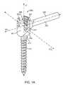
- FIG. 1Ais a perspective view of an embodiment of a polyaxial screw body.
- FIG. 1Bis an elevational view of the polyaxial screw body of FIG. 1A .
- FIG. 1Cis an elevational view of another embodiment of a polyaxial screw body.
- FIG. 2is an end-on view, taken generally along the line 2 in FIG. 1B , of vertical planes passing through orientations of a lateral connector relative to a body member.
- FIG. 3Ais a perspective view of another embodiment of a polyaxial screw body.
- FIG. 3Bis an elevational view of the polyaxial screw body of FIG. 3A .
- FIG. 4is an end-on view, taken generally along the line 4 in FIG. 3B , of orientations of a lateral connector relative to a body member.
- FIG. 5illustrates a spinal joint immobilization system affixed to a human Sacroiliac region and including a polyaxial pedicle screw of the current invention.
- the term “longitudinal”refers to a direction oriented generally parallel to an imaginary centerline of a lumen disposed through a body member, as further described herein below.
- the terms “lateral” and “transverse”refer to being oriented generally in any direction other than parallel to longitudinal.
- a polyaxial pedicle screw 108 of the current inventionis attached to the other pedicle of the L5 vertebra.
- the polyaxial pedicle screw 108 of the current inventionincludes a lateral connector 116 extending integrally therefrom.
- the integrally extending lateral connector 116facilitates a proper connection between the stabilization rod 110 b and the polyaxial pedicle screw 104 via the polyaxial pedicle screw 108 .
- an embodiment of an improved polyaxial screw body 300comprises a body member 301 and a lateral connector 302 extending integrally from the body member 301 , as illustrated in FIGS. 1A and 1B .
- the body member 301includes a side wall 303 that defines a lumen 305 disposed longitudinally through the body member 301 and having first and second ends proximate first and second ends 307 , 309 of the body member 301 .
- a pedicle screw 311may extend from the lumen 305 through an opening 313 at the second end of the lumen 305 .
- the opening 313includes an interior surface disposed in the side wall 303 thereabout. The interior surface is adapted to accommodate a head portion of the pedicle screw 311 .
- the opening 313includes a curvilinear interior surface disposed in the wall 303 thereabout.
- the curvilinear interior surfacemay be adapted to accommodate a head portion, for example, a spherical head portion of a pedicle screw 311 .
- An example of a body member 301 that may be useful in the present inventionis disclosed in Purcell et al., U.S. Pat. No. 7,377,923, which is incorporated by reference in its entirety herein.
- a channel 315is defined by a pair of apertures 317 , for example, holes or axially extending open ended slots 317 oppositely disposed through the side wall 303 .
- the slots 317include an open end facing the first end 307 of the body member 301 , as illustrated in FIGS. 1A , 1 B, 2 , 3 A, 3 B, and 4 , such that a fixation rod may be loaded into the slots 317 from the open and accommodated therebetween.
- the slots 317are smaller at an open end than at a closed end thereof, thereby providing a snap fit and/or inhibiting removal of the fixation rod from the slots 317 .
- the apertures 317comprise holes 317 , as illustrated in FIG. 1C .
- a fixation rodis loaded into the hole 317 along the channel 315 .
- the channel 315is oriented transverse and generally perpendicular to the lumen 305 .
- the lateral connector 302may include various orientations relative to the lumen 305 and the channel 315 of the body member 301 .
- the utility of the polyaxial screw body 300benefits from a medical professional's ability to select the orientation of the lateral connector 302 relative to the body member 301 . Given the crowding of the surgical site, a particular orientation of the lateral connector 302 relative to the body member 301 may be superior to other orientations of the lateral connector 302 relative to the body member 301 . Thus, providing the medical professional a choice from a spectrum of orientations not only increases the utility of the screw body 300 , but also allows the medical professional to provide optimal care to a patient by selecting the optimum relative orientation of the lateral connector 302 .
- the body member 301is viewed end on from the first end 307 .
- an infinite number of orientations of a linecan be encompassed in planes generally parallel to the centerline LC L of the lumen 305 .
- Each line 314 , 316 , 318 , 320 , 322 , 324 , 326 , 328 , 330 having arrows at ends thereof in FIG. 2represents a possible orientation of the line OC L line relative to the lumen 305 .
- all illustrated orientations of the lines 314 , 316 , 318 , 320 , 322 , 324 , 326 , 328 , 330lie in planes generally parallel to the lumen 305 .
- a planar group 400 of orientationscan be defined to include all practically unique orientations of the lateral connectors 302 that lie in planes generally parallel to the lumen 305 .
- the planar group 400includes all the orientations represented by the lines 314 , 316 , 318 , 320 , 322 , 324 , 326 , 328 , 330 illustrated in FIG. 2 .
- a first sub-group 402 of the planar group 400 of orientations of the lateral connector 302includes all practically unique orientations that lie in planes that are generally perpendicular to a plane formed by the centerline CC L of the transverse channel 315 and the centerline LC L of the lumen 305 and generally parallel to the lumen 305 .
- lines 314 , 316 , and 318each represent an example of an orientation of the lateral connector 302 that lies in a plane that is generally perpendicular to the transverse channel 315 and generally parallel to the lumen 305 .
- the lines 314 , 316 , and 318are members of the first sub-group 402 .
- the lateral connector 302extends from the side wall 303 in a plane that is generally perpendicular to the transverse channel 315 and generally parallel to the lumen 305 .
- the lateral connector 302extends in a direction that is generally perpendicular to a plane formed by the centerline LC L of the lumen 105 and the centerline CC L of the channel 315 . Therefore, in this embodiment, the lateral connector 302 is a member of the first sub-group 402 of the planar group 400 of orientations.
- the lateral connector 302is integral with the side wall 304 and is adapted to attach to a member of a pelvic fixation device.
- the lateral connector 302is partially hollow, whereas in other embodiments the lateral connector 302 is a tubular or solid member.
- the lateral connector 302may be threaded on a portion thereof, for example, a distal end thereof, as illustrated in FIG. 1B , or over an entirety thereof as known in the art. Threads 304 may be applied to an exterior surface 306 or an interior surface of the lateral connector 302 .
- the lateral connector 302may include other connection mechanisms such as, for example, a bayonet socket connection, a spring loaded button and aperture connection, a cotter pin connection, and others as may be known in the art.
- the lateral connector 302may have any cross-sectional shape as known in the art, including by way of example and not limitation, circular, elliptical, ovoid, or polygonal including any number of straight line or curvilinear sides.
- the lateral connector 302may extend from the body member 301 from anywhere along a longitudinal extent of the body member 301 from the first end 307 to the second end 309 .
- the lateral connector 302may extend from the body member 301 proximate the first end 307 or proximate the second end 309 , as illustrated by the dashed lines 308 , 310 , respectively in FIG. 1B , or anywhere in between the first and second ends 307 , 309 , as illustrated, for example, at 312 .
- Each orientation 308 , 310 , 312 of the lateral member 302lies in a plane that is generally perpendicular to the transverse channel 315 and generally parallel to the lumen 305 , and thus within the first sub-group 402 of orientations.
- a lateral connector 302extends from the side wall 303 in an orientation 332 in a plane that is generally perpendicular to the transverse channel 315 and generally parallel to the lumen 305 .
- the lateral connector 302extends away from the body member 301 generally towards the first end 307 .
- the lateral connector 332may extend from the polyaxial screw body 350 in a direction relatively toward the first end 307 or relatively toward the second end 309 from anywhere along the length of the body member 301 from the first end 307 to the second end 309 , as illustrated by the dashed lines 336 , 338 in FIG. 3B .
- each orientation 332 , 336 , and 338 of the lateral connector 302lies in a plane that is generally perpendicular to the transverse channel 315 and generally parallel to the lumen 305 , and thus within the first sub-group 402 of orientations.
- the first sub-group 402 of orientationsincludes lateral connectors 302 that extend from the body member 301 from proximate a first end 317 a of the channel 315 , proximate a second end 317 b of the channel 315 , or anywhere in between the first and second ends of the channel 315 , as represented by the lines 314 , 318 , and 316 , respectively, as shown in FIG. 2 .
- the lateral connector 302is illustrated by dashed lines 334 as having a curvilinear orientation in at least one plane.
- the orientation 334was curved in only the plane of the paper (including a distal end 335 , as illustrated in FIG. 3B )
- the orientation 334would lie entirely in a plane that is generally perpendicular to the transverse channel 315 and generally parallel to the lumen 305 , thus making the orientation 334 a member of the first sub-group 402 .
- the orientation 334includes a curve into or out of the plane of the paper (including a distal end 337 , as illustrated in FIG. 3B )
- the orientation 334would lie in more than a single plane and would therefore belong to a group of practically unique orientations that is external to the planar group 400 , which we shall call the curvilinear group 500 .
- Each member of the curvilinear group 500may extend from the body member 301 from any position relative to the transverse channel 315 , for example, as illustrated by lines 314 , 316 , and 318 of FIG. 2 , or any position along a longitudinal extent of the body member 301 from the first end 307 to the second end 309 (See FIGS. 1B and 3B ).
- a second sub-group 404 of the planar group 400 of orientations of the lateral connector 302includes those that are generally co-planar with the lumen 305 , but not necessarily generally perpendicular to the transverse channel 315 .
- the lines 316 and 330lie in planes that include the lumen 305 , thus, the lines 316 and 330 represent orientations that are part of the second sub-group 404 .
- orientations represented by the dashed lines 308 and 310 , and the lines 312 and 316are members of both the first sub-group 402 and the second sub-group 404 .
- the remaining lines, 320 , 322 , 324 , 326 , and 328 illustrated in FIG. 2lie in planes that are neither generally co-planar with the lumen 305 nor generally perpendicular to the transverse channel 315 , and thus represent orientations that are members of a third sub-group 406 of the planar group 400 .
- a polyaxial screw body 375includes a lateral member, such as for example, any of the lateral members 377 , 379 , 381 , or 383 .
- Each of the lateral members 377 , 379 , 381 , or 383may extend from the body member 301 from any position relative to the transverse channel 315 , for example, as illustrated by lines 314 , 316 , and 318 of FIG. 2 , or any position along a longitudinal extent of the body member 301 from the first end 307 to the second end 309 (See FIGS. 2B and 3B ).
- the lateral members 377 , 379 , 381 , 383may have any rotational orientation relative to the transverse channel 315 .
- the lateral members 377 , 379 , 381 , 383may extend from the body member 301 at any angle relative to the lumen 305 .
- the lateral connectors 377 , 379 , 381 , 381are part of the third sub-group 406 of practically unique orientations including members that lie in a plane generally parallel to the lumen 305 , but are not generally co-planar with the lumen 305 or generally perpendicular to the transverse channel 315 .
- orientation 387 represented by dashed linesis not a member of the third sub-group 406 , but is a member of the first sub-group 402 and the second sub-group 404 .
- the groups of practically unique orientations presented hereinaboveprovide a convenient way to classify all of the possible practically unique orientations of the lateral connector 302 relative to the body member 301 .
- a global group comprising of all orientationswould include the curvilinear group 500 and the planar group 400 as sub-groups thereof.
- the planar group 400includes the first, second, and third sub-groups 402 , 404 , 406 , as defined hereinabove. Note that there are practically unique orientations that are members of both the first and second sub-groups 402 and 404 .
- the lateral connectors 302may integrally extend from the body member 301 in any of the practically unique orientations described hereinabove and the polyaxial screw bodies 300 , 350 , 375 may be manufactured from methods as known in the art, including by way of example and not limitation, casting, machining, or combinations of casting and machining.
- Material for the polyaxial screw bodies 300 , 350 , 375may be a suitable material as known in the art, including by way of example and not limitation stainless steel, Nitinol or titanium, stainless steel, other shape memory metal materials, other metals, plastic, synthetic material, other suitable materials, or any combination thereof.
- each of the sub-groups 402 , 404 , 406 , and the curvilinear group 500 defined hereinaboverefer to groups of practically unique orientations and not groups of mathematically possible orientations
- each of the sub-groups 402 , 404 , 406 , and the curvilinear group 500does not include an infinite number of members. Rather, because the number of practically unique orientations is limited by the finite size and shape of the body member 301 and the lateral member 302 and the tolerances of modern manufacturing techniques, each of the sub-groups 402 , 404 , 406 , and the curvilinear group 500 includes a finite, albeit large, number of members.
- a lateral connectorintegrally extends from a body member of the polyaxial screw body to utilize less space than a conventional polyaxial screw body utilizing a conventional fixation rod connector.
- the lateral connectormay integrally extend from the body member in any orientation as desired to provide a medical professional a choice in selection of the optimum orientation.
Landscapes
- Health & Medical Sciences (AREA)
- Orthopedic Medicine & Surgery (AREA)
- Surgery (AREA)
- Neurology (AREA)
- Life Sciences & Earth Sciences (AREA)
- Biomedical Technology (AREA)
- Nuclear Medicine, Radiotherapy & Molecular Imaging (AREA)
- Engineering & Computer Science (AREA)
- Heart & Thoracic Surgery (AREA)
- Medical Informatics (AREA)
- Molecular Biology (AREA)
- Animal Behavior & Ethology (AREA)
- General Health & Medical Sciences (AREA)
- Public Health (AREA)
- Veterinary Medicine (AREA)
- Neurosurgery (AREA)
- Surgical Instruments (AREA)
Abstract
Description
Claims (1)
Priority Applications (2)
| Application Number | Priority Date | Filing Date | Title |
|---|---|---|---|
| US13/277,439US8834540B2 (en) | 2010-10-20 | 2011-10-20 | Polyaxial bone screw with lateral connector |
| US14/454,005US9308028B2 (en) | 2010-10-20 | 2014-08-07 | Polyaxial bone screw with lateral connector |
Applications Claiming Priority (3)
| Application Number | Priority Date | Filing Date | Title |
|---|---|---|---|
| US39486510P | 2010-10-20 | 2010-10-20 | |
| US41130310P | 2010-11-08 | 2010-11-08 | |
| US13/277,439US8834540B2 (en) | 2010-10-20 | 2011-10-20 | Polyaxial bone screw with lateral connector |
Related Child Applications (1)
| Application Number | Title | Priority Date | Filing Date |
|---|---|---|---|
| US14/454,005ContinuationUS9308028B2 (en) | 2010-10-20 | 2014-08-07 | Polyaxial bone screw with lateral connector |
Publications (2)
| Publication Number | Publication Date |
|---|---|
| US20120101533A1 US20120101533A1 (en) | 2012-04-26 |
| US8834540B2true US8834540B2 (en) | 2014-09-16 |
Family
ID=45973613
Family Applications (2)
| Application Number | Title | Priority Date | Filing Date |
|---|---|---|---|
| US13/277,439ActiveUS8834540B2 (en) | 2010-10-20 | 2011-10-20 | Polyaxial bone screw with lateral connector |
| US14/454,005ActiveUS9308028B2 (en) | 2010-10-20 | 2014-08-07 | Polyaxial bone screw with lateral connector |
Family Applications After (1)
| Application Number | Title | Priority Date | Filing Date |
|---|---|---|---|
| US14/454,005ActiveUS9308028B2 (en) | 2010-10-20 | 2014-08-07 | Polyaxial bone screw with lateral connector |
Country Status (5)
| Country | Link |
|---|---|
| US (2) | US8834540B2 (en) |
| EP (1) | EP2629688A4 (en) |
| JP (1) | JP5671146B2 (en) |
| BR (1) | BR112013009776A2 (en) |
| WO (1) | WO2012054744A2 (en) |
Cited By (1)
| Publication number | Priority date | Publication date | Assignee | Title |
|---|---|---|---|---|
| US10258386B2 (en)* | 2017-06-15 | 2019-04-16 | Warsaw Orthopedic, Inc. | Spinal construct and method |
Families Citing this family (23)
| Publication number | Priority date | Publication date | Assignee | Title |
|---|---|---|---|---|
| US8100946B2 (en) | 2005-11-21 | 2012-01-24 | Synthes Usa, Llc | Polyaxial bone anchors with increased angulation |
| US9439681B2 (en) | 2007-07-20 | 2016-09-13 | DePuy Synthes Products, Inc. | Polyaxial bone fixation element |
| JP5815407B2 (en) | 2008-09-12 | 2015-11-17 | ジンテス ゲゼルシャフト ミット ベシュレンクテル ハフツング | Spinal stabilization and guided fixation system |
| KR20110081208A (en) | 2008-09-29 | 2011-07-13 | 신세스 게엠바하 | Multi-Axis Bottom-Loading Screw and Rod Assemblies |
| CA2742399A1 (en) | 2008-11-03 | 2010-06-03 | Dustin M. Harvey | Uni-planar bone fixation assembly |
| KR20120013312A (en) | 2009-04-15 | 2012-02-14 | 신세스 게엠바하 | Orthodontic Connectors for Spinal Structures |
| CA2764841A1 (en) | 2009-06-17 | 2010-12-23 | Synthes Usa, Llc | Revision connector for spinal constructs |
| US9814493B2 (en)* | 2009-10-12 | 2017-11-14 | Globus Medical, Inc. | Trans-iliac connector |
| US8758411B1 (en) | 2011-10-25 | 2014-06-24 | Nuvasive, Inc. | Implants and methods for treating spinal disorders |
| EP3326558B1 (en) | 2011-11-14 | 2025-04-30 | The University of British Columbia | Intramedullary fixation system for management of pelvic and acetabular fractures |
| US20150157362A1 (en)* | 2013-12-05 | 2015-06-11 | Warsaw Orthopedic, Inc. | Spinal implant system and method |
| WO2015134750A1 (en) | 2014-03-06 | 2015-09-11 | University Of British Columbia | Shape adaptable intramedullary fixation device |
| JP6389002B2 (en) | 2014-10-14 | 2018-09-12 | ザ ユニヴァーシティ オブ ブリティッシュ コロンビア | System and method for intramedullary bone fixation |
| US11547450B2 (en)* | 2015-04-17 | 2023-01-10 | Apifix Ltd. | Expandable polyaxial spinal system |
| US10307185B2 (en)* | 2016-03-29 | 2019-06-04 | Globus Medical, Inc. | Revision connectors, systems, and methods thereof |
| US10413330B2 (en)* | 2016-08-09 | 2019-09-17 | Warsaw Orthopedic, Inc. | Spinal implant system and method |
| EP3522803A4 (en) | 2016-10-05 | 2020-05-27 | The University of British Columbia | Intramedullary fixation device with shape locking interface |
| US11109895B2 (en)* | 2016-10-26 | 2021-09-07 | Warsaw Orthopedic, Inc. | Spinal construct |
| KR102365489B1 (en)* | 2017-09-27 | 2022-02-18 | 상하이 산유 메디컬 씨오., 엘티디. | Adjustable Dual Slot Spinal Internal Fixture and Bone Screw |
| RU184913U1 (en)* | 2018-01-09 | 2018-11-14 | ФЕДЕРАЛЬНОЕ ГОСУДАРСТВЕННОЕ БЮДЖЕТНОЕ УЧРЕЖДЕНИЕ "НАУЧНО-ИССЛЕДОВАТЕЛЬСКИЙ ДЕТСКИЙ ОРТОПЕДИЧЕСКИЙ ИНСТИТУТ ИМЕНИ Г.И. ТУРНЕРА" Министерства здравоохранения Российской Федерации | Device for the surgical treatment of children with caudal regression of type 4 according to the classification of T.S. Renshaw |
| CN112912022A (en) | 2018-10-17 | 2021-06-04 | 不列颠哥伦比亚大学 | Bone fixation device and system |
| US10918421B2 (en)* | 2019-05-07 | 2021-02-16 | Warsaw Orthopedic, Inc. | Spinal implant system and methods of use |
| US11571244B2 (en)* | 2019-05-22 | 2023-02-07 | Nuvasive, Inc. | Posterior spinal fixation screws |
Citations (11)
| Publication number | Priority date | Publication date | Assignee | Title |
|---|---|---|---|---|
| US20070135817A1 (en) | 2005-12-08 | 2007-06-14 | Ensign Michael D | Percutaneous screw assembly |
| US20080125816A1 (en) | 2003-08-28 | 2008-05-29 | Jackson Roger P | Polyaxial bone screw with split retainer ring |
| US20080215095A1 (en)* | 2007-02-23 | 2008-09-04 | Lutz Biedermann | Stabilization device for stabilizing bones of a vertebra and rod connector used therefor |
| US20080243189A1 (en) | 2003-05-22 | 2008-10-02 | Alphatec Spine, Inc., | Variable angle spinal screw assembly |
| US20080269810A1 (en)* | 2007-04-12 | 2008-10-30 | Texas Scottish Rite Hospital For Children | Orthopedic Fastener for Stabilization and Fixation |
| US20100036420A1 (en)* | 2004-03-31 | 2010-02-11 | Depuy Spine, Inc. | Head-to-head connector spinal fixation system |
| US20100037098A1 (en) | 2008-08-11 | 2010-02-11 | International Business Machines Corporation | Terminate operations for complex i/o link |
| US7892260B2 (en)* | 2006-10-06 | 2011-02-22 | Depuy Spine, Inc. | Unilateral placement |
| US20110270325A1 (en)* | 2008-09-29 | 2011-11-03 | Thomas Keyer | Polyaxial bottom-loading screw and rod assembly |
| US8083777B2 (en)* | 2007-06-15 | 2011-12-27 | Robert Reid, Inc. | System and method for polyaxially adjustable bone anchorage |
| US20120071926A1 (en)* | 2010-09-16 | 2012-03-22 | Jani Mehul R | Transverse Connector |
Family Cites Families (9)
| Publication number | Priority date | Publication date | Assignee | Title |
|---|---|---|---|---|
| FR2686500B1 (en)* | 1992-01-23 | 1998-11-27 | Euros Sa | PROSTHETIC ASSEMBLY, PARTICULARLY FOR LUMB-SACRED ARTICULATION. |
| US5498262A (en)* | 1992-12-31 | 1996-03-12 | Bryan; Donald W. | Spinal fixation apparatus and method |
| AU2001270720B2 (en)* | 2000-06-30 | 2007-02-08 | Henry Graf | Intervertebral linking device |
| US6485491B1 (en)* | 2000-09-15 | 2002-11-26 | Sdgi Holdings, Inc. | Posterior fixation system |
| CA2664591C (en)* | 2006-09-26 | 2014-12-02 | Synthes Usa, Llc | Transconnector |
| CA2694010C (en)* | 2007-07-19 | 2015-04-21 | Synthes Usa, Llc | Clamps used for interconnecting a bone anchor to a rod |
| PL2170192T3 (en)* | 2007-07-20 | 2011-07-29 | Synthes Gmbh | Polyaxial bone fixation element |
| US20100087864A1 (en) | 2008-10-03 | 2010-04-08 | Assaf Klein | Fastener assembly that fastens to polyaxial pedicle screw |
| US8758411B1 (en)* | 2011-10-25 | 2014-06-24 | Nuvasive, Inc. | Implants and methods for treating spinal disorders |
- 2011
- 2011-10-20USUS13/277,439patent/US8834540B2/enactiveActive
- 2011-10-20EPEP11835155.0Apatent/EP2629688A4/ennot_activeWithdrawn
- 2011-10-20BRBR112013009776Apatent/BR112013009776A2/ennot_activeIP Right Cessation
- 2011-10-20WOPCT/US2011/057126patent/WO2012054744A2/enactiveApplication Filing
- 2011-10-20JPJP2013535095Apatent/JP5671146B2/ennot_activeExpired - Fee Related
- 2014
- 2014-08-07USUS14/454,005patent/US9308028B2/enactiveActive
Patent Citations (11)
| Publication number | Priority date | Publication date | Assignee | Title |
|---|---|---|---|---|
| US20080243189A1 (en) | 2003-05-22 | 2008-10-02 | Alphatec Spine, Inc., | Variable angle spinal screw assembly |
| US20080125816A1 (en) | 2003-08-28 | 2008-05-29 | Jackson Roger P | Polyaxial bone screw with split retainer ring |
| US20100036420A1 (en)* | 2004-03-31 | 2010-02-11 | Depuy Spine, Inc. | Head-to-head connector spinal fixation system |
| US20070135817A1 (en) | 2005-12-08 | 2007-06-14 | Ensign Michael D | Percutaneous screw assembly |
| US7892260B2 (en)* | 2006-10-06 | 2011-02-22 | Depuy Spine, Inc. | Unilateral placement |
| US20080215095A1 (en)* | 2007-02-23 | 2008-09-04 | Lutz Biedermann | Stabilization device for stabilizing bones of a vertebra and rod connector used therefor |
| US20080269810A1 (en)* | 2007-04-12 | 2008-10-30 | Texas Scottish Rite Hospital For Children | Orthopedic Fastener for Stabilization and Fixation |
| US8083777B2 (en)* | 2007-06-15 | 2011-12-27 | Robert Reid, Inc. | System and method for polyaxially adjustable bone anchorage |
| US20100037098A1 (en) | 2008-08-11 | 2010-02-11 | International Business Machines Corporation | Terminate operations for complex i/o link |
| US20110270325A1 (en)* | 2008-09-29 | 2011-11-03 | Thomas Keyer | Polyaxial bottom-loading screw and rod assembly |
| US20120071926A1 (en)* | 2010-09-16 | 2012-03-22 | Jani Mehul R | Transverse Connector |
Cited By (1)
| Publication number | Priority date | Publication date | Assignee | Title |
|---|---|---|---|---|
| US10258386B2 (en)* | 2017-06-15 | 2019-04-16 | Warsaw Orthopedic, Inc. | Spinal construct and method |
Also Published As
| Publication number | Publication date |
|---|---|
| WO2012054744A2 (en) | 2012-04-26 |
| BR112013009776A2 (en) | 2016-07-19 |
| EP2629688A2 (en) | 2013-08-28 |
| US20120101533A1 (en) | 2012-04-26 |
| WO2012054744A3 (en) | 2012-07-05 |
| US9308028B2 (en) | 2016-04-12 |
| JP5671146B2 (en) | 2015-02-18 |
| US20140350603A1 (en) | 2014-11-27 |
| JP2013545514A (en) | 2013-12-26 |
| EP2629688A4 (en) | 2016-08-03 |
Similar Documents
| Publication | Publication Date | Title |
|---|---|---|
| US9308028B2 (en) | Polyaxial bone screw with lateral connector | |
| US12035949B2 (en) | Percutaneous transverse connector system | |
| US8475499B2 (en) | Rod to rod connectors and methods of adjusting the length of a spinal rod construct | |
| JP5599316B2 (en) | Surgical fixation system and related methods | |
| US9439699B2 (en) | Percutaneous access devices and bone anchor assemblies | |
| US20060155283A1 (en) | Occipital plate and guide systems | |
| JP5743128B2 (en) | Methods and systems for translaminar spinal fixation | |
| US20100049206A1 (en) | Insertion assembly for minimally invasive spinal surgery | |
| US8348981B2 (en) | Minimal access occipital plate | |
| EP3285667B1 (en) | Tethering screw system | |
| US9173687B2 (en) | Fulcrum cap for spinal constructs | |
| US8591551B2 (en) | Linked spinal stabilization elements for spinal fixation | |
| EP2595553A2 (en) | Extensions for spinal anchors | |
| US20240341815A1 (en) | Minimally invasive surgery add on screw system | |
| US11109894B2 (en) | Apparatus, system, and method for spinal vertebrae stabilization | |
| US11944357B2 (en) | Minimally invasive surgery add on screw system | |
| US20240206918A1 (en) | Minimally invasive surgery add on screw system | |
| JP2007152115A (en) | Box shape chamber with rod contact part for partial contact |
Legal Events
| Date | Code | Title | Description |
|---|---|---|---|
| AS | Assignment | Owner name:ALPHATEC SPINE, INC., CALIFORNIA Free format text:ASSIGNMENT OF ASSIGNORS INTEREST;ASSIGNORS:PURCELL, THOMAS;REIMERS, DARREN;SIGNING DATES FROM 20101005 TO 20101104;REEL/FRAME:027337/0405 | |
| AS | Assignment | Owner name:MIDCAP FINANCIAL, LLC, MARYLAND Free format text:SECURITY AGREEMENT;ASSIGNORS:ALPHATEC HOLDINGS, INC.;ALPHATEC SPINE, INC.;ALPHATEC INTERNATIONAL LLC;AND OTHERS;REEL/FRAME:028358/0193 Effective date:20120607 | |
| AS | Assignment | Owner name:DEERFIELD SPECIAL SITUATIONS INTERNATIONAL MASTER Free format text:SECURITY INTEREST;ASSIGNORS:ALPHATEC HOLDINGS, INC.;ALPHATEC SPINE, INC.;ALPHATEC INTERNATIONAL LLC;AND OTHERS;REEL/FRAME:032551/0037 Effective date:20140317 Owner name:DEERFIELD PRIVATE DESIGN INTERNATIONAL II, L.P., N Free format text:SECURITY INTEREST;ASSIGNORS:ALPHATEC HOLDINGS, INC.;ALPHATEC SPINE, INC.;ALPHATEC INTERNATIONAL LLC;AND OTHERS;REEL/FRAME:032551/0037 Effective date:20140317 Owner name:DEERFIELD SPECIAL SITUATIONS FUND, L.P., NEW YORK Free format text:SECURITY INTEREST;ASSIGNORS:ALPHATEC HOLDINGS, INC.;ALPHATEC SPINE, INC.;ALPHATEC INTERNATIONAL LLC;AND OTHERS;REEL/FRAME:032551/0037 Effective date:20140317 Owner name:DEERFIELD PRIVATE DESIGN FUND II, L.P., NEW YORK Free format text:SECURITY INTEREST;ASSIGNORS:ALPHATEC HOLDINGS, INC.;ALPHATEC SPINE, INC.;ALPHATEC INTERNATIONAL LLC;AND OTHERS;REEL/FRAME:032551/0037 Effective date:20140317 | |
| STCF | Information on status: patent grant | Free format text:PATENTED CASE | |
| AS | Assignment | Owner name:ALPHATEC PACIFIC, INC., CALIFORNIA Free format text:RELEASE BY SECURED PARTY;ASSIGNORS:DEERFIELD PRIVATE DESIGN FUND II, L.P.;DEERFIELD PRIVATE DESIGN INTERNATIONAL II, L.P.;DEERFIELD SPECIAL SITUATIONS FUND, L.P.;AND OTHERS;REEL/FRAME:039950/0360 Effective date:20160901 Owner name:ALPHATEC SPINE, INC., CALIFORNIA Free format text:RELEASE BY SECURED PARTY;ASSIGNORS:DEERFIELD PRIVATE DESIGN FUND II, L.P.;DEERFIELD PRIVATE DESIGN INTERNATIONAL II, L.P.;DEERFIELD SPECIAL SITUATIONS FUND, L.P.;AND OTHERS;REEL/FRAME:039950/0360 Effective date:20160901 Owner name:ALPHATEC HOLDINGS, INC., CALIFORNIA Free format text:RELEASE BY SECURED PARTY;ASSIGNORS:DEERFIELD PRIVATE DESIGN FUND II, L.P.;DEERFIELD PRIVATE DESIGN INTERNATIONAL II, L.P.;DEERFIELD SPECIAL SITUATIONS FUND, L.P.;AND OTHERS;REEL/FRAME:039950/0360 Effective date:20160901 Owner name:ALPHATEC INTERNATIONAL LLC, CALIFORNIA Free format text:RELEASE BY SECURED PARTY;ASSIGNORS:DEERFIELD PRIVATE DESIGN FUND II, L.P.;DEERFIELD PRIVATE DESIGN INTERNATIONAL II, L.P.;DEERFIELD SPECIAL SITUATIONS FUND, L.P.;AND OTHERS;REEL/FRAME:039950/0360 Effective date:20160901 | |
| AS | Assignment | Owner name:GLOBUS MEDICAL, INC., PENNSYLVANIA Free format text:INTELLECTUAL PROPERTY SECURITY AGREEMENT;ASSIGNORS:ALPHATEC HOLDINGS, INC.;ALPHATEC SPINE, INC.;REEL/FRAME:040108/0202 Effective date:20160901 | |
| MAFP | Maintenance fee payment | Free format text:PAYMENT OF MAINTENANCE FEE, 4TH YR, SMALL ENTITY (ORIGINAL EVENT CODE: M2551) Year of fee payment:4 | |
| AS | Assignment | Owner name:ALPHATEC HOLDINGS, INC., CALIFORNIA Free format text:RELEASE BY SECURED PARTY;ASSIGNOR:GLOBUS MEDICAL, INC.;REEL/FRAME:047485/0084 Effective date:20181107 Owner name:ALPHATEC SPINE, INC., CALIFORNIA Free format text:RELEASE BY SECURED PARTY;ASSIGNOR:GLOBUS MEDICAL, INC.;REEL/FRAME:047485/0084 Effective date:20181107 | |
| AS | Assignment | Owner name:SQUADRON MEDICAL FINANCE SOLUTIONS LLC, CONNECTICUT Free format text:SECURITY INTEREST;ASSIGNORS:ALPHATEC HOLDINGS, INC.;ALPHATEC SPINE, INC.;REEL/FRAME:047494/0562 Effective date:20181106 Owner name:SQUADRON MEDICAL FINANCE SOLUTIONS LLC, CONNECTICU Free format text:SECURITY INTEREST;ASSIGNORS:ALPHATEC HOLDINGS, INC.;ALPHATEC SPINE, INC.;REEL/FRAME:047494/0562 Effective date:20181106 | |
| AS | Assignment | Owner name:ALPHATEC SPINE, INC., CALIFORNIA Free format text:RELEASE BY SECURED PARTY;ASSIGNOR:MIDCAP FUNDING IV TRUST;REEL/FRAME:052832/0132 Effective date:20200529 Owner name:ALPHATEC HOLDINGS, INC., DELAWARE Free format text:RELEASE BY SECURED PARTY;ASSIGNOR:MIDCAP FUNDING IV TRUST;REEL/FRAME:052832/0132 Effective date:20200529 | |
| AS | Assignment | Owner name:ALPHATEC HOLDINGS, INC., CALIFORNIA Free format text:RELEASE OF SECURITY INTEREST IN PATENT COLLATERAL AT REEL/FRAME NO. 47494/0562;ASSIGNOR:SQUADRON MEDICAL FINANCE SOLUTIONS LLC;REEL/FRAME:057177/0687 Effective date:20210804 Owner name:ALPHATEC SPINE, INC., CALIFORNIA Free format text:RELEASE OF SECURITY INTEREST IN PATENT COLLATERAL AT REEL/FRAME NO. 47494/0562;ASSIGNOR:SQUADRON MEDICAL FINANCE SOLUTIONS LLC;REEL/FRAME:057177/0687 Effective date:20210804 | |
| FEPP | Fee payment procedure | Free format text:ENTITY STATUS SET TO UNDISCOUNTED (ORIGINAL EVENT CODE: BIG.); ENTITY STATUS OF PATENT OWNER: LARGE ENTITY | |
| MAFP | Maintenance fee payment | Free format text:PAYMENT OF MAINTENANCE FEE, 8TH YEAR, LARGE ENTITY (ORIGINAL EVENT CODE: M1552); ENTITY STATUS OF PATENT OWNER: LARGE ENTITY Year of fee payment:8 | |
| AS | Assignment | Owner name:ALPHATEC SPINE, INC., CALIFORNIA Free format text:RELEASE OF SECURITY INTEREST IN INTELLECTUAL PROPERTY AT REEL/FRAME NO. 028358/0193;ASSIGNOR:MIDCAP FUNDING IV TRUST, AS SUCCESSOR-IN-INTEREST TO MIDCAP FINANCIAL, LLC;REEL/FRAME:061553/0787 Effective date:20220922 Owner name:ALPHATEC HOLDINGS, INC., CALIFORNIA Free format text:RELEASE OF SECURITY INTEREST IN INTELLECTUAL PROPERTY AT REEL/FRAME NO. 028358/0193;ASSIGNOR:MIDCAP FUNDING IV TRUST, AS SUCCESSOR-IN-INTEREST TO MIDCAP FINANCIAL, LLC;REEL/FRAME:061553/0787 Effective date:20220922 | |
| AS | Assignment | Owner name:MIDCAP FUNDING IV TRUST, MARYLAND Free format text:SECURITY INTEREST;ASSIGNORS:ALPHATEC SPINE, INC.;SAFEOP SURGICAL, INC.;REEL/FRAME:062310/0001 Effective date:20230106 | |
| AS | Assignment | Owner name:WILMINGTON TRUST, NATIONAL ASSOCIATION, DELAWARE Free format text:SECURITY INTEREST;ASSIGNORS:ALPHATEC SPINE, INC.;SAFEOP SURGICAL, INC.;REEL/FRAME:062681/0020 Effective date:20230106 |