US8834487B2 - Systems and methods for preventing intravasation during intrauterine procedures - Google Patents
Systems and methods for preventing intravasation during intrauterine proceduresDownload PDFInfo
- Publication number
- US8834487B2 US8834487B2US12/842,775US84277510AUS8834487B2US 8834487 B2US8834487 B2US 8834487B2US 84277510 AUS84277510 AUS 84277510AUS 8834487 B2US8834487 B2US 8834487B2
- Authority
- US
- United States
- Prior art keywords
- uterus
- sheath
- distension
- intravasation
- site
- Prior art date
- Legal status (The legal status is an assumption and is not a legal conclusion. Google has not performed a legal analysis and makes no representation as to the accuracy of the status listed.)
- Active, expires
Links
- 238000000034methodMethods0.000titleclaimsabstractdescription122
- 239000007788liquidSubstances0.000claimsabstractdescription13
- 210000004291uterusAnatomy0.000claimsdescription105
- 210000003679cervix uteriAnatomy0.000claimsdescription65
- 230000010339dilationEffects0.000claimsdescription46
- 238000012800visualizationMethods0.000claimsdescription39
- 201000010260leiomyomaDiseases0.000claimsdescription28
- 238000003780insertionMethods0.000claimsdescription20
- 230000037431insertionEffects0.000claimsdescription20
- 206010046798Uterine leiomyomaDiseases0.000claimsdescription7
- 208000010579uterine corpus leiomyomaDiseases0.000claimsdescription4
- 201000007954uterine fibroidDiseases0.000claimsdescription4
- 230000002265preventionEffects0.000claims15
- 208000002193PainDiseases0.000abstractdescription10
- 230000036407painEffects0.000abstractdescription10
- 230000008901benefitEffects0.000abstractdescription4
- 208000000399Procedural PainDiseases0.000abstract1
- 238000011084recoveryMethods0.000abstract1
- 210000001519tissueAnatomy0.000description117
- 239000012530fluidSubstances0.000description71
- 238000012377drug deliveryMethods0.000description65
- 229940079593drugDrugs0.000description61
- 239000003814drugSubstances0.000description61
- 230000006870functionEffects0.000description34
- 230000002620ureteric effectEffects0.000description33
- 210000003101oviductAnatomy0.000description26
- 238000010276constructionMethods0.000description15
- 239000000243solutionSubstances0.000description15
- 230000000087stabilizing effectEffects0.000description15
- 238000001802infusionMethods0.000description12
- 238000012546transferMethods0.000description12
- 210000001215vaginaAnatomy0.000description12
- 238000004458analytical methodMethods0.000description11
- 230000008859changeEffects0.000description11
- 239000003795chemical substances by applicationSubstances0.000description11
- 238000002224dissectionMethods0.000description11
- 239000000835fiberSubstances0.000description11
- 239000003193general anesthetic agentSubstances0.000description11
- NNJVILVZKWQKPM-UHFFFAOYSA-NLidocaineChemical compoundCCN(CC)CC(=O)NC1=C(C)C=CC=C1CNNJVILVZKWQKPM-UHFFFAOYSA-N0.000description10
- 229940035674anestheticsDrugs0.000description10
- 230000000740bleeding effectEffects0.000description10
- 238000004891communicationMethods0.000description10
- 229960004194lidocaineDrugs0.000description10
- 239000000463materialSubstances0.000description9
- 238000002604ultrasonographyMethods0.000description9
- 238000002679ablationMethods0.000description8
- 239000013078crystalSubstances0.000description8
- 230000000916dilatatory effectEffects0.000description8
- 238000007493shaping processMethods0.000description8
- 230000036772blood pressureEffects0.000description7
- 239000003550markerSubstances0.000description7
- 230000007246mechanismEffects0.000description7
- 229910052751metalInorganic materials0.000description7
- 239000002184metalSubstances0.000description7
- 230000001225therapeutic effectEffects0.000description7
- 206010053567CoagulopathiesDiseases0.000description6
- 206010028980NeoplasmDiseases0.000description6
- 230000035602clottingEffects0.000description6
- HLXZNVUGXRDIFK-UHFFFAOYSA-Nnickel titaniumChemical compound[Ti].[Ti].[Ti].[Ti].[Ti].[Ti].[Ti].[Ti].[Ti].[Ti].[Ti].[Ni].[Ni].[Ni].[Ni].[Ni].[Ni].[Ni].[Ni].[Ni].[Ni].[Ni].[Ni].[Ni].[Ni]HLXZNVUGXRDIFK-UHFFFAOYSA-N0.000description6
- 229910001000nickel titaniumInorganic materials0.000description6
- 230000003287optical effectEffects0.000description6
- 239000004033plasticSubstances0.000description6
- 229920003023plasticPolymers0.000description6
- 239000008280bloodSubstances0.000description5
- 210000004369bloodAnatomy0.000description5
- 238000000576coating methodMethods0.000description5
- 238000002405diagnostic procedureMethods0.000description5
- 230000035515penetrationEffects0.000description5
- 238000012545processingMethods0.000description5
- 238000002560therapeutic procedureMethods0.000description5
- FAPWRFPIFSIZLT-UHFFFAOYSA-MSodium chlorideChemical compound[Na+].[Cl-]FAPWRFPIFSIZLT-UHFFFAOYSA-M0.000description4
- 230000003444anaesthetic effectEffects0.000description4
- 230000000712assemblyEffects0.000description4
- 238000000429assemblyMethods0.000description4
- 210000003205muscleAnatomy0.000description4
- 230000008569processEffects0.000description4
- 230000005855radiationEffects0.000description4
- 230000002040relaxant effectEffects0.000description4
- 230000029058respiratory gaseous exchangeEffects0.000description4
- 239000011780sodium chlorideSubstances0.000description4
- 208000007536ThrombosisDiseases0.000description3
- 239000000560biocompatible materialSubstances0.000description3
- 210000004204blood vesselAnatomy0.000description3
- 201000011510cancerDiseases0.000description3
- 239000011248coating agentSubstances0.000description3
- 150000001875compoundsChemical class0.000description3
- 238000005516engineering processMethods0.000description3
- 230000005484gravityEffects0.000description3
- 238000003306harvestingMethods0.000description3
- 208000015181infectious diseaseDiseases0.000description3
- 238000002347injectionMethods0.000description3
- 239000007924injectionSubstances0.000description3
- 208000014674injuryDiseases0.000description3
- 230000002934lysing effectEffects0.000description3
- 238000005259measurementMethods0.000description3
- 150000002739metalsChemical class0.000description3
- 210000001672ovaryAnatomy0.000description3
- 230000000149penetrating effectEffects0.000description3
- 239000000523sampleSubstances0.000description3
- 238000009987spinningMethods0.000description3
- 230000008733traumaEffects0.000description3
- 238000009810tubal ligationMethods0.000description3
- WQZGKKKJIJFFOK-GASJEMHNSA-NGlucoseNatural productsOC[C@H]1OC(O)[C@H](O)[C@@H](O)[C@@H]1OWQZGKKKJIJFFOK-GASJEMHNSA-N0.000description2
- 239000004677NylonSubstances0.000description2
- 208000037062PolypsDiseases0.000description2
- 208000012287ProlapseDiseases0.000description2
- 244000258044Solanum giloSpecies0.000description2
- 239000004809TeflonSubstances0.000description2
- 229920006362Teflon®Polymers0.000description2
- 230000009471actionEffects0.000description2
- 238000000149argon plasma sinteringMethods0.000description2
- 210000001367arteryAnatomy0.000description2
- TZCXTZWJZNENPQ-UHFFFAOYSA-Lbarium sulfateChemical compound[Ba+2].[O-]S([O-])(=O)=OTZCXTZWJZNENPQ-UHFFFAOYSA-L0.000description2
- 238000007405data analysisMethods0.000description2
- 230000001066destructive effectEffects0.000description2
- 208000037265diseases, disorders, signs and symptomsDiseases0.000description2
- 208000035475disorderDiseases0.000description2
- 230000009977dual effectEffects0.000description2
- 230000002357endometrial effectEffects0.000description2
- 230000035558fertilityEffects0.000description2
- 239000008103glucoseSubstances0.000description2
- 239000007943implantSubstances0.000description2
- 229920001778nylonPolymers0.000description2
- 210000000056organAnatomy0.000description2
- 230000002285radioactive effectEffects0.000description2
- 229910052761rare earth metalInorganic materials0.000description2
- 150000002910rare earth metalsChemical class0.000description2
- 230000002787reinforcementEffects0.000description2
- 238000002271resectionMethods0.000description2
- 229910001220stainless steelInorganic materials0.000description2
- 239000010935stainless steelSubstances0.000description2
- 238000012414sterilization procedureMethods0.000description2
- 239000000126substanceSubstances0.000description2
- 230000002792vascularEffects0.000description2
- UCTWMZQNUQWSLP-VIFPVBQESA-N(R)-adrenalineChemical compoundCNC[C@H](O)C1=CC=C(O)C(O)=C1UCTWMZQNUQWSLP-VIFPVBQESA-N0.000description1
- 229930182837(R)-adrenalineNatural products0.000description1
- 241000272525Anas platyrhynchosSpecies0.000description1
- 241000894006BacteriaSpecies0.000description1
- 201000009273EndometriosisDiseases0.000description1
- 230000005355Hall effectEffects0.000description1
- 241000124008MammaliaSpecies0.000description1
- 241001465754MetazoaSpecies0.000description1
- 208000028389Nerve injuryDiseases0.000description1
- 241000405070PercophidaeSpecies0.000description1
- 206010053648Vascular occlusionDiseases0.000description1
- 230000002159abnormal effectEffects0.000description1
- 230000004913activationEffects0.000description1
- 210000003484anatomyAnatomy0.000description1
- -1anestheticsChemical class0.000description1
- 230000002924anti-infective effectEffects0.000description1
- 230000002965anti-thrombogenic effectEffects0.000description1
- 230000002785anti-thrombosisEffects0.000description1
- 229940124350antibacterial drugDrugs0.000description1
- 229960004676antithrombotic agentDrugs0.000description1
- 238000013459approachMethods0.000description1
- 238000001574biopsyMethods0.000description1
- 230000017531blood circulationEffects0.000description1
- 230000036770blood supplyEffects0.000description1
- 238000009954braidingMethods0.000description1
- 239000004067bulking agentSubstances0.000description1
- 208000019065cervical carcinomaDiseases0.000description1
- 239000000599controlled substanceSubstances0.000description1
- 238000001816coolingMethods0.000description1
- 238000005336crackingMethods0.000description1
- 210000003717douglas' pouchAnatomy0.000description1
- 201000003511ectopic pregnancyDiseases0.000description1
- 210000004696endometriumAnatomy0.000description1
- 230000002708enhancing effectEffects0.000description1
- 229960005139epinephrineDrugs0.000description1
- 210000003238esophagusAnatomy0.000description1
- 210000002388eustachian tubeAnatomy0.000description1
- 239000000284extractSubstances0.000description1
- 230000001815facial effectEffects0.000description1
- 230000004720fertilizationEffects0.000description1
- 238000001914filtrationMethods0.000description1
- 238000002594fluoroscopyMethods0.000description1
- 239000006260foamSubstances0.000description1
- 210000000232gallbladderAnatomy0.000description1
- 230000036541healthEffects0.000description1
- 210000002216heartAnatomy0.000description1
- 229940088597hormoneDrugs0.000description1
- 239000005556hormoneSubstances0.000description1
- 238000003384imaging methodMethods0.000description1
- 238000002513implantationMethods0.000description1
- 238000001727in vivoMethods0.000description1
- 238000002690local anesthesiaMethods0.000description1
- 210000004072lungAnatomy0.000description1
- 238000013507mappingMethods0.000description1
- 229910052753mercuryInorganic materials0.000description1
- 150000002730mercuryChemical class0.000description1
- 230000003278mimic effectEffects0.000description1
- 230000004048modificationEffects0.000description1
- 238000012986modificationMethods0.000description1
- 210000000214mouthAnatomy0.000description1
- 239000003158myorelaxant agentSubstances0.000description1
- 230000008764nerve damageEffects0.000description1
- 230000002853ongoing effectEffects0.000description1
- 238000009806oophorectomyMethods0.000description1
- 239000013307optical fiberSubstances0.000description1
- 208000025661ovarian cystDiseases0.000description1
- RVTZCBVAJQQJTK-UHFFFAOYSA-Noxygen(2-);zirconium(4+)Chemical compound[O-2].[O-2].[Zr+4]RVTZCBVAJQQJTK-UHFFFAOYSA-N0.000description1
- 210000003695paranasal sinusAnatomy0.000description1
- 239000002245particleSubstances0.000description1
- 230000037361pathwayEffects0.000description1
- 229920000642polymerPolymers0.000description1
- 230000035935pregnancyEffects0.000description1
- 108090000623proteins and genesProteins0.000description1
- 210000000664rectumAnatomy0.000description1
- 230000001105regulatory effectEffects0.000description1
- 238000005070samplingMethods0.000description1
- 238000007790scrapingMethods0.000description1
- 210000002784stomachAnatomy0.000description1
- 238000001356surgical procedureMethods0.000description1
- 230000001732thrombotic effectEffects0.000description1
- 230000007704transitionEffects0.000description1
- 210000003708urethraAnatomy0.000description1
- 210000003932urinary bladderAnatomy0.000description1
- 208000012991uterine carcinomaDiseases0.000description1
- 208000021331vascular occlusion diseaseDiseases0.000description1
- 239000005526vasoconstrictor agentSubstances0.000description1
- 210000003462veinAnatomy0.000description1
- 229940088594vitaminDrugs0.000description1
- 239000011782vitaminSubstances0.000description1
- 229930003231vitaminNatural products0.000description1
- 235000013343vitaminNutrition0.000description1
Images


Classifications
- A—HUMAN NECESSITIES
- A61—MEDICAL OR VETERINARY SCIENCE; HYGIENE
- A61B—DIAGNOSIS; SURGERY; IDENTIFICATION
- A61B17/00—Surgical instruments, devices or methods
- A61B17/42—Gynaecological or obstetrical instruments or methods
- A—HUMAN NECESSITIES
- A61—MEDICAL OR VETERINARY SCIENCE; HYGIENE
- A61B—DIAGNOSIS; SURGERY; IDENTIFICATION
- A61B17/00—Surgical instruments, devices or methods
- A61B17/12—Surgical instruments, devices or methods for ligaturing or otherwise compressing tubular parts of the body, e.g. blood vessels or umbilical cord
- A61B17/12022—Occluding by internal devices, e.g. balloons or releasable wires
- A61B17/12027—Type of occlusion
- A61B17/1204—Type of occlusion temporary occlusion
- A61B17/12045—Type of occlusion temporary occlusion double occlusion, e.g. during anastomosis
- A—HUMAN NECESSITIES
- A61—MEDICAL OR VETERINARY SCIENCE; HYGIENE
- A61B—DIAGNOSIS; SURGERY; IDENTIFICATION
- A61B17/00—Surgical instruments, devices or methods
- A61B17/12—Surgical instruments, devices or methods for ligaturing or otherwise compressing tubular parts of the body, e.g. blood vessels or umbilical cord
- A61B17/12022—Occluding by internal devices, e.g. balloons or releasable wires
- A61B17/12099—Occluding by internal devices, e.g. balloons or releasable wires characterised by the location of the occluder
- A—HUMAN NECESSITIES
- A61—MEDICAL OR VETERINARY SCIENCE; HYGIENE
- A61B—DIAGNOSIS; SURGERY; IDENTIFICATION
- A61B17/00—Surgical instruments, devices or methods
- A61B17/12—Surgical instruments, devices or methods for ligaturing or otherwise compressing tubular parts of the body, e.g. blood vessels or umbilical cord
- A61B17/12022—Occluding by internal devices, e.g. balloons or releasable wires
- A61B17/12131—Occluding by internal devices, e.g. balloons or releasable wires characterised by the type of occluding device
- A61B17/12136—Balloons
- A—HUMAN NECESSITIES
- A61—MEDICAL OR VETERINARY SCIENCE; HYGIENE
- A61B—DIAGNOSIS; SURGERY; IDENTIFICATION
- A61B17/00—Surgical instruments, devices or methods
- A61B17/32—Surgical cutting instruments
- A61B17/320016—Endoscopic cutting instruments, e.g. arthroscopes, resectoscopes
- A61B17/32002—Endoscopic cutting instruments, e.g. arthroscopes, resectoscopes with continuously rotating, oscillating or reciprocating cutting instruments
- A—HUMAN NECESSITIES
- A61—MEDICAL OR VETERINARY SCIENCE; HYGIENE
- A61B—DIAGNOSIS; SURGERY; IDENTIFICATION
- A61B18/00—Surgical instruments, devices or methods for transferring non-mechanical forms of energy to or from the body
- A61B18/18—Surgical instruments, devices or methods for transferring non-mechanical forms of energy to or from the body by applying electromagnetic radiation, e.g. microwaves
- A61B18/20—Surgical instruments, devices or methods for transferring non-mechanical forms of energy to or from the body by applying electromagnetic radiation, e.g. microwaves using laser
- A—HUMAN NECESSITIES
- A61—MEDICAL OR VETERINARY SCIENCE; HYGIENE
- A61B—DIAGNOSIS; SURGERY; IDENTIFICATION
- A61B17/00—Surgical instruments, devices or methods
- A61B17/02—Surgical instruments, devices or methods for holding wounds open, e.g. retractors; Tractors
- A61B17/0218—Surgical instruments, devices or methods for holding wounds open, e.g. retractors; Tractors for minimally invasive surgery
- A—HUMAN NECESSITIES
- A61—MEDICAL OR VETERINARY SCIENCE; HYGIENE
- A61B—DIAGNOSIS; SURGERY; IDENTIFICATION
- A61B18/00—Surgical instruments, devices or methods for transferring non-mechanical forms of energy to or from the body
- A61B18/02—Surgical instruments, devices or methods for transferring non-mechanical forms of energy to or from the body by cooling, e.g. cryogenic techniques
- A—HUMAN NECESSITIES
- A61—MEDICAL OR VETERINARY SCIENCE; HYGIENE
- A61B—DIAGNOSIS; SURGERY; IDENTIFICATION
- A61B18/00—Surgical instruments, devices or methods for transferring non-mechanical forms of energy to or from the body
- A61B18/04—Surgical instruments, devices or methods for transferring non-mechanical forms of energy to or from the body by heating
- A61B18/12—Surgical instruments, devices or methods for transferring non-mechanical forms of energy to or from the body by heating by passing a current through the tissue to be heated, e.g. high-frequency current
- A61B18/14—Probes or electrodes therefor
- A61B18/1485—Probes or electrodes therefor having a short rigid shaft for accessing the inner body through natural openings
- A—HUMAN NECESSITIES
- A61—MEDICAL OR VETERINARY SCIENCE; HYGIENE
- A61B—DIAGNOSIS; SURGERY; IDENTIFICATION
- A61B18/00—Surgical instruments, devices or methods for transferring non-mechanical forms of energy to or from the body
- A61B18/18—Surgical instruments, devices or methods for transferring non-mechanical forms of energy to or from the body by applying electromagnetic radiation, e.g. microwaves
- A61B18/20—Surgical instruments, devices or methods for transferring non-mechanical forms of energy to or from the body by applying electromagnetic radiation, e.g. microwaves using laser
- A61B18/22—Surgical instruments, devices or methods for transferring non-mechanical forms of energy to or from the body by applying electromagnetic radiation, e.g. microwaves using laser the beam being directed along or through a flexible conduit, e.g. an optical fibre; Couplings or hand-pieces therefor
- A61B19/24—
- A—HUMAN NECESSITIES
- A61—MEDICAL OR VETERINARY SCIENCE; HYGIENE
- A61B—DIAGNOSIS; SURGERY; IDENTIFICATION
- A61B17/00—Surgical instruments, devices or methods
- A61B2017/00017—Electrical control of surgical instruments
- A61B2017/00022—Sensing or detecting at the treatment site
- A61B2017/00026—Conductivity or impedance, e.g. of tissue
- A—HUMAN NECESSITIES
- A61—MEDICAL OR VETERINARY SCIENCE; HYGIENE
- A61B—DIAGNOSIS; SURGERY; IDENTIFICATION
- A61B17/00—Surgical instruments, devices or methods
- A61B2017/00831—Material properties
- A61B2017/00867—Material properties shape memory effect
- A—HUMAN NECESSITIES
- A61—MEDICAL OR VETERINARY SCIENCE; HYGIENE
- A61B—DIAGNOSIS; SURGERY; IDENTIFICATION
- A61B17/00—Surgical instruments, devices or methods
- A61B17/32—Surgical cutting instruments
- A61B17/320016—Endoscopic cutting instruments, e.g. arthroscopes, resectoscopes
- A61B17/32002—Endoscopic cutting instruments, e.g. arthroscopes, resectoscopes with continuously rotating, oscillating or reciprocating cutting instruments
- A61B2017/320024—Morcellators, e.g. having a hollow cutting tube with an annular cutter for morcellating and removing tissue
- A—HUMAN NECESSITIES
- A61—MEDICAL OR VETERINARY SCIENCE; HYGIENE
- A61B—DIAGNOSIS; SURGERY; IDENTIFICATION
- A61B17/00—Surgical instruments, devices or methods
- A61B17/32—Surgical cutting instruments
- A61B17/320016—Endoscopic cutting instruments, e.g. arthroscopes, resectoscopes
- A61B17/32002—Endoscopic cutting instruments, e.g. arthroscopes, resectoscopes with continuously rotating, oscillating or reciprocating cutting instruments
- A61B2017/320028—Endoscopic cutting instruments, e.g. arthroscopes, resectoscopes with continuously rotating, oscillating or reciprocating cutting instruments with reciprocating movements
- A—HUMAN NECESSITIES
- A61—MEDICAL OR VETERINARY SCIENCE; HYGIENE
- A61B—DIAGNOSIS; SURGERY; IDENTIFICATION
- A61B17/00—Surgical instruments, devices or methods
- A61B17/42—Gynaecological or obstetrical instruments or methods
- A61B2017/4216—Operations on uterus, e.g. endometrium
- A—HUMAN NECESSITIES
- A61—MEDICAL OR VETERINARY SCIENCE; HYGIENE
- A61B—DIAGNOSIS; SURGERY; IDENTIFICATION
- A61B17/00—Surgical instruments, devices or methods
- A61B17/42—Gynaecological or obstetrical instruments or methods
- A61B2017/4216—Operations on uterus, e.g. endometrium
- A61B2017/4225—Cervix uteri
- A—HUMAN NECESSITIES
- A61—MEDICAL OR VETERINARY SCIENCE; HYGIENE
- A61B—DIAGNOSIS; SURGERY; IDENTIFICATION
- A61B17/00—Surgical instruments, devices or methods
- A61B17/42—Gynaecological or obstetrical instruments or methods
- A61B2017/4233—Operations on Fallopian tubes, e.g. sterilization
- A61B2019/5217—
- A61B2019/5276—
- A—HUMAN NECESSITIES
- A61—MEDICAL OR VETERINARY SCIENCE; HYGIENE
- A61B—DIAGNOSIS; SURGERY; IDENTIFICATION
- A61B90/00—Instruments, implements or accessories specially adapted for surgery or diagnosis and not covered by any of the groups A61B1/00 - A61B50/00, e.g. for luxation treatment or for protecting wound edges
- A61B90/36—Image-producing devices or illumination devices not otherwise provided for
- A61B90/361—Image-producing devices, e.g. surgical cameras
- A61B2090/3614—Image-producing devices, e.g. surgical cameras using optical fibre
- A—HUMAN NECESSITIES
- A61—MEDICAL OR VETERINARY SCIENCE; HYGIENE
- A61B—DIAGNOSIS; SURGERY; IDENTIFICATION
- A61B90/00—Instruments, implements or accessories specially adapted for surgery or diagnosis and not covered by any of the groups A61B1/00 - A61B50/00, e.g. for luxation treatment or for protecting wound edges
- A61B90/36—Image-producing devices or illumination devices not otherwise provided for
- A61B90/37—Surgical systems with images on a monitor during operation
- A61B2090/378—Surgical systems with images on a monitor during operation using ultrasound
- A—HUMAN NECESSITIES
- A61—MEDICAL OR VETERINARY SCIENCE; HYGIENE
- A61B—DIAGNOSIS; SURGERY; IDENTIFICATION
- A61B2217/00—General characteristics of surgical instruments
- A61B2217/002—Auxiliary appliance
- A61B2217/005—Auxiliary appliance with suction drainage system
- A—HUMAN NECESSITIES
- A61—MEDICAL OR VETERINARY SCIENCE; HYGIENE
- A61B—DIAGNOSIS; SURGERY; IDENTIFICATION
- A61B2217/00—General characteristics of surgical instruments
- A61B2217/002—Auxiliary appliance
- A61B2217/007—Auxiliary appliance with irrigation system
- A—HUMAN NECESSITIES
- A61—MEDICAL OR VETERINARY SCIENCE; HYGIENE
- A61B—DIAGNOSIS; SURGERY; IDENTIFICATION
- A61B90/00—Instruments, implements or accessories specially adapted for surgery or diagnosis and not covered by any of the groups A61B1/00 - A61B50/00, e.g. for luxation treatment or for protecting wound edges
- A61B90/02—Devices for expanding tissue, e.g. skin tissue
- A—HUMAN NECESSITIES
- A61—MEDICAL OR VETERINARY SCIENCE; HYGIENE
- A61N—ELECTROTHERAPY; MAGNETOTHERAPY; RADIATION THERAPY; ULTRASOUND THERAPY
- A61N5/00—Radiation therapy
- A61N5/10—X-ray therapy; Gamma-ray therapy; Particle-irradiation therapy
- A61N5/1001—X-ray therapy; Gamma-ray therapy; Particle-irradiation therapy using radiation sources introduced into or applied onto the body; brachytherapy
- A61N5/1014—Intracavitary radiation therapy
- A61N5/1016—Gynaecological radiation therapy
Definitions
- the present inventionrelates to systems, methods, apparatus and devices for performing one or more gynecologic and urologic procedures. More particularly, devices and combinations of devices provide simplified use and enhanced safety to support performance of various diagnostic and therapeutic procedures in the doctor's office setting.
- gynecologic productsare difficult to use and often have limited use and functionality. Treatment of gynecologic disorders and ailments is most often performed in a hospital and bears a large cost due to the setting and the support personnel required. Treatment options and modalities are also limited, such that the patient may not be offered the best option for her particular condition.
- a method of preventing intravasation during an intrauterine procedurecomprises the steps of transcervically accessing the uterus with an elongate tubular sheath.
- a mechanical distension deviceis introduced through the sheath and into the uterus.
- the mechanical distension deviceis used to distend the uterus and expose a site.
- a therapeutic or diagnostic proceduremay be performed at the site.
- the transcervically accessing stepmay comprise advancing the sheath over a guidewire.
- the transcervically accessing stepmay be accomplished under local anesthesia.
- the mechanical distension stepachieves an equivalent distension to that achieved by introduction of a liquid distension media at a pressure of at least about 40 mm Hg. In some embodiments, the mechanical distension step is utilized to achieve an equivalent distension to that achieved by introduction of a liquid distension media at a pressure of at least about 70 mm Hg.
- the methodmay additionally comprise the step of dilating the cervix prior to the transcervically accessing step.
- the performing a procedure stepmay comprise treating a uterine fibroid.
- a method of performing a procedure in the uteruscomprises the steps of transcervically accessing the uterus with an elongate flexible tubular sheath, having a proximal end, a distal end and at least one lumen extending therethrough.
- the sheathhas an outside diameter of no more than about 9 mm.
- the uterusis distended to expose a site, and a visualization device is introduced through the sheath to visualize the site.
- a procedureis performed at the site.
- the proceduremay be a diagnostic procedure or a therapeutic procedure.
- the outside diameter of the sheathis less than about 8 mm, generally less than about 7 mm, and preferably less than about 6 mm.
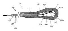
- FIG. 1illustrates a perspective view of an exemplary embodiment of an introducer consistent with the present invention
- FIG. 1Aillustrates a side sectional view of another exemplary embodiment of an introducer consistent with the present invention, wherein the introducer includes a pre-dilating balloon and is shown being deployed in the cervix of a patient;
- FIG. 1Billustrates a side sectional view of another exemplary embodiment of an introducer consistent with the present invention, wherein the introducer includes a drug delivery element and a strain gauge and is shown deployed in the cervix of a patient;
- FIG. 2illustrates a side sectional view of an exemplary embodiment of a system of the present invention, wherein an introducer includes a radiopaque ring and is shown deployed in the cervix, and a tissue removal device with a side-saddle camera has been advanced through the introducer and into the uterus of a patient;
- FIG. 2Aillustrates a side sectional view of the distal end of a tissue removal device consistent with the present invention, wherein the device includes an oscillating cutter;
- FIG. 2Billustrates a side sectional view of the distal end of another tissue removal device consistent with the present invention, wherein the device includes a rotating cutter;
- FIG. 2Cillustrates a side sectional view of the distal end of a tissue removal device and side-saddle camera, consistent with the present invention
- FIG. 3illustrates a side sectional view of another exemplary embodiment of a system consistent with the present invention, wherein an introducer is shown deployed in the cervix of a patient, and a subsonic treatment device has been advanced through the introducer and into the uterus;
- FIG. 3Aillustrates a side view of the distal end of the subsonic treatment device of FIG. 3 ;
- FIG. 4illustrates a side view of another exemplary embodiment of an introducer consistent with the present invention, wherein the introducer includes a removable needle assembly and an inflatable balloon near its distal end;
- FIG. 5illustrates a side sectional view of another exemplary embodiment of a system consistent with the present invention, wherein an introducer is shown deployed through the vaginal wall of a patient and a treatment device has been advanced through the introducer to a location outside the uterus and proximate a fibroid in the uteral wall;
- FIG. 5Aillustrates a side sectional view of another exemplary embodiment of a system consistent with the present invention, wherein an introducer is shown deployed through the vaginal wall of a patient, a treatment device including a magnet in its distal portion has been advanced through the introducer to a location outside the uterus and a stabilizing magnetic device has been advanced into the uterus proximate a fibroid;
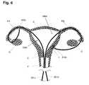
- FIG. 6illustrates a side sectional view of an exemplary method consistent with the present invention, wherein a first treatment device has been advanced through the cervix and a fallopian tube and is accessing the outside of a fallopian tube, and a second treatment device has been advanced through the cervix and a fallopian tube and is accessing the outside of the uterus proximate a fibroid;
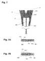
- FIG. 7illustrates a side sectional view of an exemplary drug delivery device consistent with the present invention, wherein the device is deployed in the cervix of the patient and integral needles are deployed into the cervical wall;
- FIG. 7Aillustrates a side sectional view of the drug delivery device of FIG. 7 , wherein the needles are in the retracted position;
- FIG. 7Billustrates a side sectional view of the drug delivery device of FIG. 7 , wherein the needles are in an deployed position
- FIG. 7Cillustrates a side sectional view of another exemplary drug delivery device consistent with the present invention, wherein the device includes a vacuum source and suction ports for attracting tissue toward a drug delivery element;
- FIG. 8illustrates a side sectional view of another exemplary drug delivery device consistent with the present invention, wherein the device is deployed in the cervix of the patient and integral exit holes allow fluid to pass into the cervical wall;
- FIG. 8Aillustrates a side view of the distal end of the drug delivery device of FIG. 8 , wherein the device is deployed over an occluding guidewire;
- FIG. 8Billustrates a side view of the proximal end of the drug delivery device of FIG. 8A .
- FIG. 9illustrates a side sectional view of another exemplary drug delivery device consistent with the present invention, wherein the device is deployed in the cervix of the patient, an integral balloon has been inflated and integral exit holes in the balloon allow fluid to pass into the cervical wall;
- FIG. 9Aillustrates a side view of the distal end of the drug delivery device of FIG. 9 , wherein the device is deployed over a guidewire and the balloon is inflated;
- FIG. 9Billustrates a side view of the proximal end of the drug delivery device of FIG. 9A .
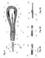
- FIG. 10illustrates a side sectional view of an exemplary scaffolding device consistent with the present invention, wherein the device has been deployed in the uterus of a patient;
- FIG. 10Aillustrates a side sectional view of the scaffolding device of FIG. 10 , wherein a control shaft has been near fully extended and a scaffold is partially deployed;
- FIG. 10Billustrates a perspective view of an exemplary scaffolding device consistent with the present invention, wherein the scaffolding assembly comprises two resiliently biased arms;
- FIG. 10Cillustrates a perspective view of an exemplary scaffolding device consistent with the present invention, wherein the scaffolding assembly includes three resiliently biased arms;
- FIG. 10Dillustrates a side sectional view of the scaffolding device of FIG. 10B , wherein the scaffolding device has been inserted through an introducer of the present invention and has its distal portion in the uterus of a patient;
- FIG. 11illustrates a side sectional view of an exemplary visualization apparatus consistent with the present invention, wherein a camera device, a first light source and a second light source have been advanced into the uterus of a patient;
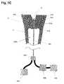
- FIG. 12illustrates a side sectional view of another exemplary system consistent with the present invention, wherein a uteral volume occupying device and a treatment device have each been advanced into the uterus of a patient;
- FIG. 12Aillustrates a side view of an exemplary wire shaping device consistent with the present invention
- FIG. 13illustrates a flow chart of an exemplary method of dilation, consistent with the present invention.
- trans-vaginal-wallrefers to devices or procedures which enter the vaginal opening, travel down the vaginal canal, and exit through the vaginal wall proximal to the cervix.
- trans-cervicalrefers to devices or procedures which enter the vaginal opening, travel down the vaginal canal, pass through the cervical canal and enter the uterus.
- trans-uteralrefers to devices or procedures which pass through the wall of the uterus.
- drugrefers to all drugs and other agents that may be included in the systems, methods apparatus and devices of the present invention; either by including the drug into a coating or an integral reservoir of a component; or by provided to the patient through other means such as via a lumen and exit port which is in fluid communication with a supply of the drug such as an infusion pump or syringe.
- Drugsshall include not only pharmaceutical compounds such as anesthetics, anti-thrombotics, thrombotics, anti-bacterial drugs and chemotherapeutics, but also other agents such as ionic solutions, hormones, genes, vitamins, clotting agents, naturally occurring substances such as extracts from plants, and any other compound or agent applicable to the procedures contained herein.
- patientrefers to any animal, such as a mammal and preferably a human. Specific examples of “patients” include but are not limited to: individuals requiring medical assistance and healthy individuals.
- Systems, methods, apparatus and devices consistent with the inventionprovide improved diagnostic and therapeutic gynecologic and urologic procedures and outcomes.
- the simplified, safer use providedallows these procedures to be performed in locations such as a doctor's office or health clinic, eliminating the high costs associated with a hospital setting.
- Specific devices of the present inventionreduce the pain encountered by the patient during and after the associated diagnostic or therapeutic procedure.
- the devices and apparatusprovide to the clinician operator precision in both manipulation and device actions, and often allow reversibility of one or more steps of the procedure without undesirable consequence.
- Inadvertent tissue traumais avoided with blunting of tips and other tissue-contacting surfaces.
- Simplified mechanisms, miniaturized geometries and improved methodsreduce procedure times and trauma, and also the associated infection risk and blood loss. Intravasation, the entry of foreign matter in a blood vessel, is also reduced.
- An introducerwhich can be placed into the patient to provide a stabile, working platform to support simplified introduction of one or more diagnostic, treatment or other devices.
- the introducerincludes an elongate shaft with one or two or more internal lumens.
- the proximal end of the shaftmay include one or more access ports, such as fluid access ports and device entry ports, as well as one or more controls such as buttons, knobs or levers used to manipulate the introducer or activate a mechanical or electronic module of the introducer.
- the introducerpreferably accepts devices comprising elongate shafts, sequentially or simultaneously.
- the introducer systemalso permits the administration and or removals of fluid from the patient, such as fluid administered to the uterus, while also providing fluid stasis or maintaining stasis to a maximum pressure at which fluid can be automatically evacuated.
- the introducer systemalso permits the administration of one or more drugs, such as anesthetic drugs or clotting agents.
- the introducer systemmay be introduced through the cervix and into the uterus, through the vaginal wall to a location outside the uterus (trans-vaginal-wall), or through another entry path to a specific anatomical location within the patient.
- the systemspreferably include one or more of the introducer, a treatment device, a tissue removal device, a subsonic treatment device, a drug delivery device, a dilating device, a vaginal-wall-crossing device, a scaffolding device, a volume occupying device, a stabilizing device, a visualization apparatus and a navigation apparatus, all of the present invention, and other devices applicable to gynecological procedures.
- the systems of the present inventionare simple to use, and provide reduced risks while enhancing outcomes.
- Treatment Deviceswhich allow a clinician to perform, individually or in combination with additional devices, one or more gynecologic and urologic procedures.
- the treatment devices providedinclude but are not limited to: devices which remove, denature or otherwise treat undesired tissue; devices which modify the structure of a vessel such as a fallopian tube or blood vessel occlusion device; drug delivery devices; and other therapeutic or diagnostic devices.
- the treatment devicespreferably include an elongate shaft, and the shaft may include one or more internal lumens.
- the proximal end of the shaftmay include one or more access ports, such as fluid access ports and device entry ports.
- a handlemay be included on the proximal end, the handle including one or more controls such as buttons, knobs or levers used to manipulate the elongate shaft or activate a mechanical or electronic module of the device.
- the treatment devices of the present inventionmay additionally or alternatively perform a diagnostic function. These treatment devices may provide multiple functions, such as diagnostic or treatment functions including applying a tamponade force to bleeding tissue or distending tissue such as uteral wall tissue.
- Treatment devicesinclude tissue removal devices which can be inserted through the introducer of the present invention and be subsequently operated to remove tissue.
- Tissue removal deviceare often arranged with vacuum assemblies which provide a vacuum proximate a tissue removal element and evacuate the tissue to be removed to a site outside of the patient's body.
- Treatment devicesinclude subsonic treatment devices which also can be inserted through the introducer of the present invention and subsequently deliver subsonic energy to disrupt or otherwise modify tissue such as a fibroid.
- Treatment devicesinclude drug delivery devices which can be placed into the patient and controllably deliver a drug to a specific area of tissue or space, such as the vaginal wall, cervix, uterus, uteral wall or fallopian tube as well as a specific fibroid, polyp, tumor or other tissue mass.
- These drug delivery devicesmay provide additional functions, such as diagnostic or treatment functions including applying a tamponade force to bleeding tissue or distending tissue such as uteral wall tissue.
- Dilating devicesare provided which can be used to dilate the cervix, a penetration tract in the vaginal wall, or other tissue.
- the dilating devicespreferably include an elongate shaft, and the shaft may include one or more internal lumens.
- the proximal end of the shaftmay include one or more access ports, such as fluid access ports and device entry ports.
- a handlemay be included on the proximal end, the handle including one or more controls such as buttons, knobs or levers used to manipulate the elongate shaft or activate a mechanical or electronic module of the device.
- Specific embodimentsinclude “smart” dilation systems and methods which measure one or more parameters (e.g. device parameters such as strain or pressure or patient parameters such as EKG, EEG, blood pressure or respiration).
- One or more algorithmsare applied to the measured parameters and used to control one or more dilation parameters such as rate, force and magnitude.
- These dilation devicesmay be integrated into another device, such as an introducer, a treatment device, or other device of the present invention.
- These dilation devicesmay provide additional or alternative functions, such as diagnostic or treatment functions including applying a tamponade force to bleeding tissue, distending tissue such as uteral wall tissue, or delivering a drug to tissue.
- the dilating devices of the present inventionare typically configured to dilate to a diameter less than 9 mm, preferably between 5 and 8 mm, and more preferably between 2 and 5 mm.
- the dilating devices of the present inventionare typically dilated to a pressure not to exceed 300 psi (e.g. balloon dilation pressure), and preferably less than 150 psi.
- Vaginal-wall-crossing devicesare provided that permit safe introduction of one or more devices, such as the introducer of the present invention, from inside the vaginal canal, through the vaginal wall to various anatomical locations including but not limited to: the outer wall of the uterus; the outer wall of the fallopian tubes; the ovaries; intra-abdominal locations; other locations and combinations thereof.
- the crossing devicespreferably include an elongate shaft, and the shaft may include one or more internal lumens.
- the proximal end of the shaftmay include one or more access ports, such as fluid access ports and device entry ports.
- a handlemay be included on the proximal end, the handle including one or more controls such as buttons, knobs or levers used to manipulate the elongate shaft or activate a mechanical or electronic module of the device.
- a guidewireis first placed through the vaginal wall, and one or more devices are placed over-the-wire. These crossing devices may provide additional or alternative functions, such as diagnostic or treatment functions including delivering a drug to tissue.
- Distension devicesare provided which can be introduced into a space, such as the uterus, and apply a force to tissue.
- the distension devicesinclude without limitation, for example, scaffolding devices or the like.
- the distension devicesare preferably inserted through the introducer of the present invention.
- the distension devicespreferably include an elongate shaft, and the shaft may include one or more internal lumens.
- the proximal end of the shaftmay include one or more access ports, such as fluid access ports and device entry ports.
- a handlemay be included on the proximal end, the handle including one or more controls such as buttons, knobs or levers used to manipulate the elongate shaft or activate a mechanical or electronic module of the device.
- These distension devicesmay provide additional or alternative functions, such as diagnostic or treatment functions including applying a tamponade force to bleeding tissue or delivering a drug to tissue.
- These distension devicesare preferably inserted into the uterus of a patient such that the scaffolding assembly preferably distends the uteral cavity to a volume equivalent to that which would be attained via a liquid distension media at a pressure of at least 40 mm of HG but not greater than 100 mm HG and preferably approximating 70 mm Hg.
- Volume Occupying devicesare provided which can be introduced into a space, such as the uterus, and occupy space within the uterus.
- the volume occupying devicesare preferably inserted through the introducer of the present invention.
- the volume occupying devicespreferably include an elongate shaft, and the shaft may include one or more internal lumens.
- the proximal end of the shaftmay include one or more access ports, such as fluid access ports and device entry ports.
- a handlemay be included on the proximal end, the handle including one or more controls such as buttons, knobs or levers used to manipulate the elongate shaft or activate a mechanical or electronic module of the device.
- volume occupying devicesprovide the function of taking up space in a cavity, such as taking up space in the uterus to reduce the amount of fluid delivered to the uterus in a diagnostic or therapeutic procedure.
- These volume occupying devicesmay provide additional or alternative functions, such as diagnostic or treatment functions including applying a tamponade force to bleeding tissue, distending tissue such as uteral wall tissue, or delivering a drug to tissue.
- Stabilizing devicesare provided which are used to stabilize one or more separate devices, such as a treatment device of the present invention.
- Stabilizing devicesmay include magnets which attract a corresponding magnet integral to the separate device such as to position a treatment device proximate to tissue to be treated.
- the stabilizing devicespreferably include an elongate shaft, and the shaft may include one or more internal lumens.
- the proximal end of the shaftmay include one or more access ports, such as fluid access ports and device entry ports.
- a handlemay be included on the proximal end, the handle including one or more controls such as buttons, knobs or levers used to manipulate the elongate shaft or activate a mechanical or electronic module of the device such as an electromagnet located in the distal portion of the shaft.
- These stabilizing devicesmay provide additional or alternative functions, such as diagnostic or treatment functions including applying a tamponade force to bleeding tissue, distending tissue such as uteral wall tissue, or delivering a drug to tissue.
- Visualization apparatusare provided which provide enhanced imaging of target anatomical locations within the patient.
- the apparatusinclude one or more of: miniaturized cameras; infrared cameras; deployable light sources; stabilizing mechanisms; image stabilizing modules and processing; and improved and cost-reduced displays (e.g. a laptop screen display).
- the visualization apparatuspreferably include one or more devices comprising an elongate shaft, and the shaft may include one or more internal lumens.
- the proximal end of the shaftmay include one or more access ports, such as fluid access ports and device entry ports.
- a handlemay be included on the proximal end, the handle including one or more controls such as buttons, knobs or levers used to manipulate the elongate shaft or activate a mechanical or electronic module of the device.
- These visualization apparatusmay provide additional or alternative functions, such as diagnostic or treatment functions including applying a tamponade force to bleeding tissue, distending tissue such as uteral wall tissue, or delivering a drug to tissue.
- Navigating apparatusare provided which enable a clinician to navigate one or more diagnostic or therapeutic devices to perform a gynecologic procedure.
- the navigation apparatuspreferably include one or more of: an electro-magnetic (EM) beacon and/or receiver; a light emitter and/or detector; and a magnetic source and/or a detector.
- the navigation apparatuspreferably include one or more devices comprising an elongate shaft, and the shaft may include one or more internal lumens.
- the proximal end of the shaftmay include one or more access ports, such as fluid access ports and device entry ports.
- a handlemay be included on the proximal end, the handle including one or more controls such as buttons, knobs or levers used to manipulate the elongate shaft or activate a mechanical or electronic module of the device.
- These navigation apparatusmay provide additional or alternative functions, such as diagnostic or treatment functions including applying a tamponade force to bleeding tissue, distending tissue such as uteral wall tissue, or delivering a drug to tissue.
- Shape-modifying wiresare provided which are slidingly received by one or more lumens of a device of the present invention, such as a morcellating or other treatment device used to access and treat a fibroid. Shapes on the one or more shaping wires can bias the elongate shaft of the device, such as at a distal portion, to a pre-determined shape. In a preferred embodiment, multiple shaping wires with varied shapes are provided to accommodate different procedures and/or access to different anatomical locations.
- Numerous devices of the present inventioninclude an elongate shaft, similar in construction to shafts used in laparoscopic and percutaneous devices.
- the shaftsmay be manufactured in a “lay up” process including multiple layers of similar or dissimilar materials, such as layers of flexible biocompatible material separated by a braided material such as metal wire or plastic filament.
- the constructionis chosen to provide adequate column strength and torqueability to access the desired anatomical locations and perform the desired actions.
- Each shaftpreferably has a blunt or otherwise atraumatic distal tip.
- the shaftsmay include one or more lumens, such as a lumen configured to slidingly receive an elongate device such as a treatment catheter or guidewire, a lumen configured to allow fluid delivery and/or fluid sampling or removal; an inflation lumen configured to allow inflation of a balloon; a mechanical linkage lumen configured to slidingly receive a cable such as to transmit force through the shaft (e.g. from a lever on a handle on the proximal end of the shaft); a lumen configured to slidingly receive a shaping wire of the present invention; other lumens and combinations thereof.
- a lumenconfigured to slidingly receive an elongate device such as a treatment catheter or guidewire, a lumen configured to allow fluid delivery and/or fluid sampling or removal
- an inflation lumenconfigured to allow inflation of a balloon
- a mechanical linkage lumenconfigured to slidingly receive a cable such as to transmit force through the shaft (e.g. from a lever on a handle on the proximal end of the shaft)
- the elongate shafts of the present inventionmay include a reinforced section such as a section located at the portion of the shaft that, when inserted into the body, is in proximity to the cervix.
- the reinforced sectioncan provide the function of preventing collapse of an internal lumen of the shaft (enhanced radial strength) as well as prevent undesired perforation out of the shaft and into tissue such as cervical tissue.
- the reinforced sectionmay comprise the braiding process described hereabove, and may be provided along a majority of length of the shaft, or a small portion.
- the shaftmay include variable stiffness along its length, and may allow the stiffness to be adjusted, such as through the insertion of a stiffening wire, or by pressurizing an internal (blind) lumen of the shaft.
- the shaftmay include along its length one or more clinician inflatable balloons, such as compliant or non-compliant nylon or PET balloons configured to dilate, deflect the device or neighboring tissue; deliver a drug; or perform another function.
- the elongate shafts of the present inventionare typically less than 9 mm in diameter, and preferably between 5 to 8 mm in diameter, and more preferably between 2 and 5 mm in diameter.
- the elongate shafts of the present inventionmay include clinician controlled deflection means, preferably one or more pull wires attached at their proximal end to a control in a handle on the proximal end of the shaft, and attached on their distal end to a portion of the shaft, such as a distal portion of the shaft. Advancement and retraction of the pull wire causes a portion of the shaft to deflect, such as to bring a treatment element of the present invention in proximity to tissue to be treated.
- the shaftsmay further include one or more internal conduits, such as wires or optical fibers which do not need to be advanced or retracted. These conduits may be embedded in the wall of the shaft, fixed to an internal lumen, or sandwiched between to layers present in a layered construction.
- Wirescan be used to transmit electrical signals or energy, in either direction in the shaft.
- Fiber optic cablescan be used to transmit light energy (e.g. laser energy) or signals (e.g. images from a lens), in either direction in the shaft.
- the shafts of the present inventioninclude a handle on their proximal end, and the handle includes on or more controls to activate one or more portions of the device.
- a “kill-switch” controlis included to allow the clinician to quickly stop an ongoing action.
- the shafts and other components of the devices of the present inventionare constructed of biocompatible materials.
- the devicesmay be configured for one-time use or be resterilizable.
- the materialsinclude medical grade metals, plastics and other materials.
- Shaped memory metalssuch as Nitinol and shaped memory polymers may be used to provide controllable material properties or meet specific elasticity and/or resiliency requirements.
- the shafts and other componentsmay include one or more coatings, such as coatings selected from the group consisting of: anti-infective drugs, anti-thrombogenic drugs; clotting agents; chemotherapeutics; anesthetics such as lidocaine; other drugs; and combinations thereof.
- the shafts and other componentsmay include drug delivery means, such as drug reservoirs (e.g.
- markersmay be integral to a component of the device, such as a marker selected from the group consisting of: visible and non-visible markers; radiopaque markers; magnetic markers; ultrasonically reflective markers; and combinations thereof.
- a functional elementmay be mounted to the shafts or other components of the devices of the present invention. These functional elements may include a sensor or transducer and/or another functional element such as a camera or marker as described hereabove.
- Applicable sensorsinclude but are not limited to: electrodes such as electrical mapping electrodes; temperature sensors; pressure sensors; strain gauges; accelerometers; force sensing resistors; position sensors such as linear or rotary encoders; magnetic sensors such as hall effect transistors; optical sensors such as phototransistors; physiologic sensors such as EKG; EEG; respiration; blood sensors such as a blood gas sensors such as an O 2 saturation sensors; glucose sensors; blood pressure sensors; pH sensors; other physiologic sensors; and combinations thereof.
- Applicable transducersinclude but are not limited to: magnets; electrodes such as radiofrequency electrodes; heat generators; cryogenic generators; force or space-occupying generators such as an expandable balloon or solenoid; drug delivery elements such as iontophoretic elements; sound transducers such as acoustic transducers, ultrasound transducers and subsonic transducers; radiation sources; light sources such as visible or infrared light sources configured to provide a beacon for navigation and ultraviolet light sources configured to treat infection or kill bacteria; visualization elements such as cameras, lenses, fiber optics and ultrasound crystals; other functional elements; and combinations thereof. Functional elements may further include elements to cause dissection of tissue, such as blunt dissection projections and fluid jets.
- the systems, methods, apparatus and devices of the present inventionare applicable to patients with one or more of the following conditions:
- fibroidse.g. fibroids attached to the wall of the uterus, in the uteral wall or on the outside of the uterus;
- cancersuch as carcinoma of the cervix or uterus
- the systems, methods, apparatus and devices of the present inventionare applicable to performing one or more therapeutic or diagnostic gynecologic and urologic procedures. These procedures may be performed inside or outside the uterus. Applicable primary procedures include but are not limited to:
- the systems, methods, apparatus and devices of the present inventionmay be used to perform one or more additional procedures, including but not limited to:
- the systems, methods, apparatus and devices of the present inventionmay provide and/or utilize various means and routes of access to an internal location within the patient. Routes of access include but are not limited to:
- trans-vaginal-walldefined above
- the devices and apparatus of the present inventionmay comprise an elongate shaft that includes one or more lumens such as to slidingly receive one or more separate devices also comprising an elongate shaft.
- the device lumensmay be configured to support over-the-wire insertion over a standard guidewire, or alternatively a side-car mounted near the distal end of the shaft may be provided to support monorail (also known as rapid exchange) insertion.
- the device lumens, such as the introducer of the present inventionmay be sized and be otherwise configured to slidingly receive one or more devices including but not limited to:
- the device lumensmay be sized and include access elements such as luer fittings to attach to drug delivery devices such as syringes and infusion pumps.
- the device elongate shaftmay be sized and otherwise configured to be passed through one or more devices including but not limited to:
- dilatorse.g. sequential dilators or balloon dilators
- introducer 100 aincludes an elongate, hollow shaft, sheath 110 , which is configured to have distal end 111 (preferably with an atraumatic leading edge) be inserted into the body of a patient, such as through the cervix and into the uterus, to provide a working channel to introduce tools through a lumen of sheath 110 and into the uterus.
- distal end 111preferably with an atraumatic leading edge
- distal end 111 of sheath 110is placed into the vaginal opening of a patient, and manipulated to penetrate through the vaginal wall (such as by advancing over a pre-existing guidewire penetrating the vaginal wall), such as to provide a working channel to introduce tools through a lumen of sheath 110 to a location outside the uterus.
- Sheath 110may be configured to slidingly receive two or more devices, independently or simultaneously.
- sheath 110includes multiple lumens along its length, each lumen configured to slidingly receive a separate device. Sheath 110 may remain in place throughout the subsequent procedure, or for a portion of the procedural steps. Sheath 110 may be repositioned during the procedure, such as to advance or withdraw sheath 110 .
- Sheath 110is manufactured from medical-grade plastics, metals and other biocompatible material such as a sheath including a Teflon outer layer.
- One or more portions of sheath 110may be radiopaque, such as by inclusion of a barium sulfate in plastic material or inclusion of one or more metal portions which provide sufficient radiopacity.
- distal end 111includes a radiopaque marker.
- Sheath 110is preferably of a braided construction as has been described hereabove, and includes a reinforced portion, reinforcement 115 (e.g.
- reinforcement 115may be configured to prevent a device inserted into sheath 110 from inadvertently puncturing out the side of sheath 110 , such as to prevent a puncture that would damage cervical or other patient tissue unexpectedly.
- device insertion port 120On the proximal end of sheath 110 is device insertion port 120 , which provides access to an internal lumen of sheath 110 and has been configured to maintain fluid stasis with or without a device inserted through it.
- Port 120preferably has an “X” cut opening through one or more diaphragms that maintain that fluid seal.
- the thicknesses of the diaphragms and the materials chosenpreferably maintain pressure up to a predetermined level (e.g. 50 mm Hg) after which fluid is automatically evacuated to prevent damage to the patient's internal tissue.
- Input valve 121 and output valve 122are input valve 121 and output valve 122 , each of which includes a standard luer connector for attachment to standard fluid infusion lines.
- Input valve 121 and output valve 122may include simple one-way valves or more sophisticated valves that open (in either direction or both) at pre-determined pressures.
- fluid infusion and fluid evacuation means(not shown but preferably gravity driven or pump driven fluid movement means), can be attached to port 121 and port 122 and control the level of fluid introduced into the patient via introducer 100 a .
- sheath 110is a single lumen and the fluid is introduced through that lumen.
- sheath 110includes multiple lumens and fluid can be delivered or evacuated through one or more lumens, simultaneously or independently.
- a volume of liquid and level of liquid pressureare used to visualize the internal space and/or provide space to manipulate one or more devices.
- a gel or gasis delivered into the patient.
- Introducer 100 amay include a handle, not shown, on its proximal end.
- the handlemay include one or more controls, as has been described hereabove.
- Sheath 110may include one or more valves within one or more lumens of sheath 110 , such as a valve near the distal end 111 .
- Introducer 100 amay include a balloon along sheath 110 , such as a balloon configured to dilate tissue such as the cervix or the vaginal wall. In an alternative embodiment, multiple balloons are employed, such as a balloon on a balloon configuration.
- Sheath 110may have an integrally mounted functional element, as has been described hereabove but preferably a pressure or force sensor used to provide information to the clinician or a system component regarding dilation conditions (reference FIG. 13 herebelow).
- Sheath 110may include one or more functional elements along its length, such as a vibrational transducer configured to assist in dilation.
- Sheath 110may include a lumen for insertion of a shaped wire, such as a wire configured to resiliently bias sheath 110 and/or a wire configured to place a “straightening” bias on the cervical canal during introducer insertion, once inserted or both.
- sheath 110includes an expandable cage structure, not shown but protruding from distal end 111 .
- the expandable cage structuremay have a fluted geometry such as a geometry configured to follow the contour of the uterus when introducer 100 a is inserted through the cervix.
- sheath 110 of Introducer 100is typically less than 9 mm in diameter and preferably less than 8 mm diameter. In another embodiment, sheath 110 is less than 7 mm in diameter. In another embodiment, sheath 110 is less than 6 mm in diameter. In another embodiment, sheath 110 is less than 5 mm in diameter. In another embodiment, sheath 110 is less than 4 mm in diameter. In another embodiment, sheath 110 is less than 3 mm in diameter. In another embodiment, sheath 110 is less than 2 mm in diameter. Sheath 110 is configured in size and rigidity to prevent painful and potentially destructive dilation of the cervix.
- Introducer 100 bhas a dual balloon construction and includes sheath 110 , of similar construction to sheath 110 of FIG. 1 .
- Introducer 100 bis shown over a guidewire 131 , such as an 0.038′′ standard interventional guidewire, which has been advanced through vagina V, through cervix C and into uterus U.
- An inflatable balloon introducer assembly 150includes balloon 151 and shaft 150 and is shown having been advanced into the cervix C of a patient and balloon 151 inflated (inflation lumen and inflation port not shown).
- Inflation of balloon 151is used to pre-dilate cervix C such that sheath 110 can be advanced into cervix C.
- Inflation balloon 151is preferably less than 9 mm in diameter when fully inflated, and more preferably between 2 and 8 mm in diameter.
- Shaft 155which is slidingly received by sheath 110 , may be pulled back prior to advancement of sheath 110 , or balloon 151 may be left in place, although preferably partially deflated prior to advancement.
- balloon assembly 150 including shaft 155 and balloon 151may be configured to be completely removed from sheath 110 such as after sheath 110 is placed to its desired location in the patient's body.
- further dilation of the cervixmay be accomplished by subsequent inflation of balloon 151 , and/or via inflation of a balloon integral to sheath 110 , balloon 116 (inflation lumen and inflation port also not shown). Inflation of either balloon 151 or balloon 116 , or both, may be used to anchor sheath 110 in place.
- device insertion port 120On the proximal end of sheath 110 is device insertion port 120 , which provides access to an internal lumen of sheath 110 and is in fluid communication with fluid transfer port 123 configured to introduce and/or remove fluid or other media through sheath 110 and into the patient as has been described hereabove.
- Port 120includes a rotating collar 124 , which can be rotated to permit devices to pass through port 120 as well as seal around those devices, such as via a diaphragm which seals around inserted devices similar to a Tuohy Borst valve configuration. Port 120 further provides fluid stasis when no device is inserted through it.
- Guidewire 131may be replaced with a different guidewire, such as with a guidewire with different stiffness or lubricious properties. Guidewire 131 may remain in place for a majority of the procedure, or may be removed early on.
- Introducer 100 cincludes sheath 110 with distal end 111 , device insertion port 120 with rotating collar 124 and fluid transfer port 123 , all of similar construction to similar components of introducer 100 a of FIG. 1 and introducer 100 b of FIG. 2 .
- Introducer 100 chas been placed over guidewire 141 and advanced such that its distal portion resides within cervix C and its distal end is within uterus U of a patient.
- Introducer 100 cincludes a force measuring element, strain gauge 113 , which is used to monitor forces exerted on sheath 110 (and the corresponding resultant forces exerted on the neighboring tissue). Wires, not shown but attached to strain gauge 113 and traveling proximally through sheath 110 , attach to an electronic module, also not shown, and provide pressure or other force information to the clinician or a system component which processes the information.
- Introducer 100 cfurther includes drug delivery element 114 , such as a drug delivery mechanism.
- Drug delivery element 114may be a simple drug coating, or may be a depot that stores a drug such as an anesthetic and delivers the drug via osmosis, iontophoresis or other drug delivery mechanism.
- drug delivery element 114is a pressure releasable sack, such as a sack with a duck bill valve, and when sufficient pressure is applied to the sac, such as via the cervix, a drug, such as lidocaine, is delivered.
- drug delivery element 114includes multiple pressure-driven sacks, such as multiple sacks in different locations and/or multiple sacks with different delivery pressure properties.
- Introducer 100 cfurther includes a visualization apparatus, visualization element 112 preferably a forward looking visualization tool such as forward looking ultrasound, or a lens that provides an image to a camera, not shown, but preferably a camera system that receives an image from a fiber optic in optical communication with the lens.
- visualization element 112preferably a forward looking visualization tool such as forward looking ultrasound, or a lens that provides an image to a camera, not shown, but preferably a camera system that receives an image from a fiber optic in optical communication with the lens.
- a displaynot shown but preferably integrated into a laptop computer via a USB or video connection, provides the camera image to the clinician and/or patient.
- System 10includes introducer 100 d and tissue removal device 200 which includes an integral visualization apparatus, camera 256 mounted to side-saddle catheter 250 .
- Introducer 100 dincludes sheath 110 , device insertion port 120 and fluid transfer port 123 , all of similar construction to similar components of introducers 100 a , 100 b and 100 c hereabove.
- Introducer 100 dhas been placed and advanced such that its distal portion resides within cervix C and its distal end provides access within uterus U of a patient.
- Sheath 110includes a marker, radiopaque ring 117 which can be used by the clinician to determine and/or confirm with fluoroscopy the diameter (e.g. the inside diameter) of sheath 110 at the location of ring 117 , such as to confirm or rule out the condition where the cervix may be undesirably compressing sheath 110 .
- ring 117is an ultrasonically reflective marker enabling the condition to determine the associated diameter by using ultrasound, such as via an ultrasound device commonly located in a gynecologist office.
- Tissue removal device 200a morcellating device, has been advanced through port 120 , through a lumen of sheath 110 , and into the uterus U of a patient.
- Tissue removal device 200includes an elongate shaft, tube 201 , which includes on its distal end 203 a cutout, window 202 .
- a cutting element 210is present within window 202 such that as the distal end of tube 201 is manipulated near tissue, cutting element 210 will cut that tissue.
- Vacuum meansnot shown put in fluid communication with a lumen of tube 201 and window 202 , evacuate the pulverized, cut or otherwise detached particles to a location outside of the patient. In a preferred embodiment, vacuum and evacuation means are integral to a handle of device 200 .
- vacuum and evacuation meansare connected to a port which is integral to a handle of device 200 .
- Cutting element 210of one or more configurations such as the configurations described below in reference to FIGS. 2A and 2B , is preferably attached to a speed control mechanism, not shown.
- the speed control mechanismis simplified for use by including one or more feedback means (e.g. electromotive feedback, rotation or other speed feedback, vibrational feedback, physiologic feedback such as EKG or blood pressure, or other feedback), wherein the feedback means can be used to automatically control the speed, greatly simplifying use for the clinician.
- the clinician available feedbackis limited to a small number of finite settings, such as less than 10 settings.
- a kill-switchis included on a handle of the device, which is readily accessible to the clinician and upon activation removes power and/or applies a breaking function to instantaneously stop the cutting motion.
- a side-saddle catheter 250which includes sleeve 252 (e.g. a Teflon sleeve) which slidingly surrounds tube 201 .
- sleeve 252e.g. a Teflon sleeve
- Advancement and retraction of an elongate shaft, shaft 205causes a visualization apparatus, camera 255 to be correspondingly advanced and retracted relative to tube 201 .
- the image received from camera 255is used by the clinician to position the window 202 of tissue removal device 200 near one or more fibroids, such as fibroid F 1 located within the wall of uterus U and fibroid F 2 attached to the wall of uterus U.
- Camera 225may utilize CCD and/or MEMS mirror control technology to produce and/or transfer an image.
- camera 225includes one or more motion sensing elements, such as miniaturized accelerometers or gyros which can be fed back to an image processing system, not shown but preferably external to the patient, such that the image provided to the clinician does not move as the camera is moved.
- side saddle catheter 250includes one or more functional elements, not shown but preferably selected from the list of functional elements provided hereabove.
- the functional elementmay be a fluid delivery port, such as a port configured to deliver saline or other clear fluid to clear the pathway of the camera view or to clean off a contaminated lens.
- FIG. 2Aa preferred embodiment of the cutting element 210 of FIG. 2 is shown.
- the distal end of tube 201 and window 202is shown with an oscillating cutter 211 attached to an elongate control linkage, shaft 221 , which is attached at its proximal end to a reciprocating motor assembly, not shown, but preferably a simplified, precision speed controlled assembly as has been described hereabove.
- the speed assemblyutilizes feedback, also as has been described hereabove.
- FIG. 2Banother preferred embodiment of the cutting element of FIG. 2 is shown.
- tube 201 and window 202is shown with an spinning or rotational cutter 212 attached to an elongate control linkage, shaft 221 , which is attached at its proximal end to a rotational motor assembly, not shown, but preferably a simplified, precision speed controlled assembly as has been described hereabove.
- the speed assemblyutilizes feedback, also as has been described hereabove.
- sheath 110 of Introducer 100is typically less than 9 mm in diameter and preferably less than 8 mm diameter.
- sheath 110is less than 7 mm in diameter.
- sheath 110is less than 6 mm in diameter.
- sheath 110is less than 5 mm in diameter.
- sheath 110is less than 4 mm in diameter.
- sheath 110is less than 3 mm in diameter.
- sheath 110is less than 2 mm in diameter.
- Sheath 110is configured in size and rigidity to prevent painful and potentially destructive dilation of the cervix.
- System 10includes introducer 100 and subsonic treatment device 300 .
- Introducer 100includes sheath 110 , device insertion port 120 and fluid transfer port 123 , all of similar construction to similar components of introducers 100 a , 100 b , 100 c and 100 d hereabove.
- Introducer 100 dhas been placed and advanced such that its distal portion resides within cervix C and its distal end provides access within uterus U of a patient.
- a treatment catheter of the present invention, acoustic generator device 300has been inserted through port 120 , down a lumen of sheath 110 and into the uterus of the patient.
- acoustic generator device 300includes acoustic transducer 310 which comprises housing 302 , preferably a metal can with a lumen 304 , and a sound crystal 303 , configured to deliver subsonic sound waves.
- System 10preferably includes specialized fluid medium, which is injected into uterus U via port 123 and sheath 110 .
- the fluid mediumis configured to adequately conduct the emitted sound waves and provide an impedance mismatch between it and the targeted tissue (e.g. endometrium), such that large amounts of energy (sufficient to destroy or otherwise denature the tissue cells) is transferred to the tissue when the subsonic waves arrive at the interface.
- Introducer 100 eis configured to puncture through tissue, such as the vaginal wall to perform a trans-vaginal-wall procedure.
- Introducer 100 eincludes sheath 110 with balloon 116 and distal end 111 , device insertion port 120 and fluid transfer port 123 , all of similar construction to similar components of introducer 100 a , 100 b , 100 c and 100 d hereabove.
- Balloon 116which can be configured to perform one or more functions such as to dilate tissue, to anchor sheath 110 in place and to maintain one or more lumens of sheath 110 in an open state under high loading conditions. Balloon 116 is in fluid communication with inflation lumen 152 and injection port 153 such that a syringe or endoflator attached to the luer of port 153 can be used to inflate balloon 116 .
- Balloon 116includes a miniaturized, integral pressure sensor 154 , which is preferably attached to one or more wires, not shown but traveling proximally and attaching to an electronic module which processes the received signal and provides pressure information to the clinician and/or utilizes the information in one or more ways such as to reduce patient pain such as via the “smart” dilation system and method described in detail in reference to FIG. 13 herebelow. Additional balloons and/or pressure sensors may be integrated into sheath 110 .
- Pull wire 171is fixedly attached at its distal end to a distal portion of sheath 110 , and it is operably attached at its proximal end to knob 172 , such that rotation of knob 172 causes sheath 170 to deflect. As shown in FIG. 4 , rotation of knob 172 that causes pull wire 172 to retract causes the distal end of sheath 110 to deflect to the left and rotation of knob 172 that causes pull wire 172 to advance causes sheath 110 to deflect to the right. In an alternative embodiment, additional one or more pull wires are included to allow a clinician to deflect sheath 110 in multiple directions at multiple points along the length of sheath 110 . Deflection of sheath 110 allows for directional orientation, positioning and advancement of the one or more treatment or other devices that can be inserted into sheath 110 via port 120 (inserted devices not shown).
- Introducer 100 eincludes a tissue penetrating assembly comprising needle 161 , an elongate hollow needle preferably constructed of stainless steel or Nitinol, which has fixedly attached on its proximal end, knob 162 .
- Needle 161resides within a lumen of sheath 110 , and is in place when introducer 100 e is advanced through tissue.
- Needle 161has an internal lumen sized to slidingly receive guidewire 131 .
- Guidewire 131can be placed trough needle 161 after needle 161 has been advanced through tissue (guidewire loaded from proximal end of needle 161 ).
- guidewire 131can be placed to a target location, such as through the vaginal wall of a patient via another needle device, and then passed through needle 161 (guidewire loaded from distal end of needle 161 ).
- needle 161can be used to deliver anesthetic to tissue prior to needle 161 and/or sheath 110 advancement.
- Introducer 100 emay have one or more functional elements, such as a functional element described hereabove and integrated into sheath 110 .
- a functional elementcomprising a visualization apparatus or a portion of a visualization apparatus, such as a camera lens and fiber optic or an ultrasound crystal and associated wiring are contained within sheath 110 .
- Advancement of sheath 110 esuch as through the vaginal wall to a location neighboring the outside of a patient's uterus, may require dissection of tissue.
- introducer 100 eincludes a functional element such as a blunt dissector, a fluid jet, or other dissection element.
- a blunt dissection devicesuch as a blunt tipped probe, electrocautery probe, or fluid-jet probe, is advanced through a lumen of sheath 110 prior to and/or during advancement of sheath 110 through tissue.
- the distal portion of sheath 110may need to be tracked, such as it is advanced through the vaginal wall at the preferred location of the anterior or posterior culdesac of the vagina, to a location outside the uterus.
- Tracking meanssuch as visualization systems and navigation systems of the present invention, may be used such as by incorporating one or more visualization or navigation elements in introducer 100 e and/or by using separate devices to navigate and/or visualize.
- a visible light sourceis placed in a fallopian tube and a camera integral to introducer 100 e or a device inserted through sheath 110 is used to locate the visible light source and access the associated fallopian tube.
- an electromagnetic transmitting antennais placed in a fallopian tube and a receiving antenna is integral to introducer 100 e or a device inserted through sheath 110 and is used to locate the transmitting source and access the associated fallopian tube.
- System 10includes introducer 100 f and treatment catheter 500 a which includes visualization element 520 and orientation apparatus 521 .
- Introducer 100 fincludes sheath 110 , device insertion port 120 and fluid transfer port 123 , all of similar construction to similar components of introducers 100 a , 100 b , 100 c , 100 d and 100 e hereabove.
- Introducer 100 fhas been advanced through the vaginal opening into the vagina V of a patient, to a distal location of the vaginal canal, proximate the cervix C.
- Sheath 110has exited through the vaginal wall, as was described hereabove in reference to FIG. 4 .
- treatment catheter 500 ahas been advanced through a lumen of sheath 110 , and further advanced, such as with manipulation via pull wires integral to introducer 100 f and/or treatment catheter 500 a , neither pull wires shown, such that the distal end of treatment catheter 500 a is proximate a fibroid F located in the wall of uterus U.
- Treatment catheter 500 aincludes shaft 501 , which includes near its distal end treatment element 510 , such as a morcellating assembly, a subsonic generator, an excisor, a cutter, an ablation element, or other tissue removal or denaturing element as has been described in detail hereabove.
- treatment element 510such as a morcellating assembly, a subsonic generator, an excisor, a cutter, an ablation element, or other tissue removal or denaturing element as has been described in detail hereabove.
- visualization element 520which is preferably a camera lens connected to a fiber optic cable and configured to produce an image on display 525 of laptop 526 via a cable, wire bundle 527 .
- visualization element 520is an ultrasound crystal or crystals such as a rotating crystal or phased array of crystals, configured to produce an image on display 525 of laptop 526 via cable 527 .
- Visualization element 520further includes orientation apparatus 521 , a nanoscale mechanism, such as a MEMS gyroscope, accelerometer or series of mercury switches, that is configured to provide movement information to an image processing unit such that the image provided to the clinician does not move as the visualization element moves.
- the image processing unitmay be integral to laptop 526 and/or another component of system 10 .
- Shaft 501which extends beyond the proximal end of introducer 100 f and exits port 120 , preferably includes on its proximal end a handle with one or more clinician controls (e.g. on-off buttons, pull wire rotational knobs, etc) and/or connections such as electrical connections to laptop computer 526 , or mechanical connections such as to motor assemblies which provide motion to visualization element 520 (e.g. to a rotating ultrasound crystal) or treatment element 510 (e.g. to a spinning or reciprocating cutting blade).
- clinician controlse.g. on-off buttons, pull wire rotational knobs, etc
- connectionssuch as electrical connections to laptop computer 526 , or mechanical connections such as to motor assemblies which provide motion to visualization element 520 (e.g. to a rotating ultrasound crystal) or treatment element 510 (e.g. to a spinning or reciprocating cutting blade).
- Anestheticssuch as lidocaine may be administered peri-procedurally (prior to, during and post procedure), via a separate device, or via one or more functional elements of introducer 100 f .
- Numerous gynecological proceduresare applicable to the system 10 and method of FIG. 5 , including but not limited to: intra-uteral procedures (re-entering uterus thus avoiding cervical crossing); uteral wall procedures (e.g. the fibroid F treatment shown); fallopian tube procedures (e.g. tubal ligation); ovary procedures (e.g. egg harvesting); cancer treatment procedures; pain treatment procedures; other tissue treatment or removal procedures, and intra-abdominal procedures.
- intra-uteral proceduresre-entering uterus thus avoiding cervical crossing
- uteral wall procedurese.g. the fibroid F treatment shown
- fallopian tube procedurese.g. tubal ligation
- ovary procedurese.g. egg harvesting
- cancer treatment procedurespain treatment procedures;
- one or more blunt dissection proceduresmay be performed in the placement of introducer 100 f and/or the advancement of one or more devices (e.g. treatment catheter 500 a ) through sheath 110 and to the target procedure location. Also as described in FIG. 4 , one or more navigation or visualization procedures or devices may be used to navigate introducer 100 f and/or treatment catheter 500 a.
- one or more devicese.g. treatment catheter 500 a
- one or more navigation or visualization procedures or devicesmay be used to navigate introducer 100 f and/or treatment catheter 500 a.
- an additional deviceis inserted through port 120 and sheath 110 , either sequentially or simultaneously with treatment catheter 500 a .
- the additional devicemay perform one or more functions such as that of a treatment device, navigation device, stabilizing device, visualization device or other device as has been described as performing a function related to the intended gynecologic and urologic procedures described throughout this application.
- treatment catheter 500 aincludes a second treatment element, of similar or dissimilar functionality to treatment element 510 .
- System 10includes introducer 100 g , treatment catheter 500 b and stabilizing device 550 .
- Introducer 100 gincludes sheath 110 , device insertion port 120 and fluid transfer port 123 , all of similar construction to similar components of introducers 100 a , 100 b , 100 c , 100 d , 100 e and 100 f hereabove.
- Introducer 100 ghas been advanced through the vaginal opening into the vagina V of a patient, to a distal location of the vaginal canal, proximate the cervix C.
- Sheath 110has exited through the vaginal wall, as was described hereabove in reference to FIG.
- Sheath 110includes drug delivery element 114 , located along sheath 110 at a location proximate the intended vaginal wall crossing, such that one or more drugs, preferably an anesthetic such as lidocaine, can be delivered to reduce pain.
- Drug delivery element 114may deliver a drug via simple infusion means such as osmosis or a weak-bonded coating transitioning into solution, or more sophisticated means such as pressure-regulated delivery or iontophoresis as has been described in detail hereabove.
- treatment catheter 500 bhas been advanced through a lumen of sheath 110 , and further advanced, such as with manipulation via pull wires integral to introducer 100 f and/or treatment catheter 500 b , neither pull wires shown, such that the distal end of treatment catheter 500 b is proximate a fibroid F located in the wall of uterus U.
- Treatment catheter 500 bincludes shaft 501 , which includes near its distal end treatment element 510 , such as a morcellating assembly, a subsonic generator, an excisor, a cutter, an ablation element, or other tissue removal or denaturing element as has been described in detail hereabove.
- System 10further includes stabilizing device 550 , inserted into the uterus through the vagina V and cervix C of the patient (outside of introducer 100 g ).
- stabilizing device 550inserted into the uterus through the vagina V and cervix C of the patient (outside of introducer 100 g ).
- a second magnet, magnet 552preferably a rare earth magnet or clinician activatable electromagnet similar or dissimilar (such as a difference in size and/or magnetic field strength) to magnet 502 of treatment catheter 550 b .
- either or both magnet 552 and magnet 502are electromagnets such that one or both magnetic fields can be deactivated for initial manipulation(s), and activated to achieve final position, such as at a location where treatment element 510 is in close proximity to uteral fibroid F, as shown in FIG. 5A .
- the magnetically guided system 10 of FIG. 5 acan perform one or more procedures without the need for a camera or other visualization apparatus.
- a camera or other visualization apparatusis used, such as with a visualization element incorporated into sheath 100 g , treatment catheter 500 b or stabilizing device 550 .
- Shaft 501which extends beyond the proximal end of introducer 100 g and exits port 120 , and shaft 551 both preferably include on their proximal end a handle with one or more clinician controls (e.g. on-off buttons, pull wire rotational knobs, etc) and/or connections such as electrical connections to a laptop computer (not shown but similar to laptop computer 526 of FIG. 5 ), or mechanical connections such as to motor assemblies which provide motion to treatment element 510 (e.g. to a spinning or reciprocating cutting blade) or to manipulate one or more internal pull wires such as to create a robotically manipulated system.
- clinician controlse.g. on-off buttons, pull wire rotational knobs, etc
- connectionssuch as electrical connections to a laptop computer (not shown but similar to laptop computer 526 of FIG. 5 ), or mechanical connections such as to motor assemblies which provide motion to treatment element 510 (e.g. to a spinning or reciprocating cutting blade) or to manipulate one or more internal pull wires such as to create a robotically manipulated system
- a first treatment device 500 cis inserted through the vaginal canal of the vagina V, through the cervix C, through the uterus U and through a fallopian tube FT 1 to a location outside the fallopian tube FT 1 .
- First treatment device 500 cincludes an elongate shaft, shaft 501 c which includes on its distal end occluding assembly 510 c , shown as a snaring assembly but alternatively an occluding clip placement assembly or an occlusive drug delivery assembly.
- Shaft 501 cpreferably includes one or more pull wires, for manipulation, and alternatively or additionally may be advancable over a previously placed guidewire.
- Shaft 501 cpreferably includes a handle on its proximal end, not shown but preferably including one or more controls such as pull wire controls and a control to synch up the snare of treatment element 510 c .
- Treatment element 510 cis shown having snared a portion of fallopian tube FT 1 such as to occlude fallopian tube FT 1 in a sterilization procedure.
- a second treatment device 500 dis inserted through the vaginal canal of the vagina V, through the cervix C, through the uterus U and through a fallopian tube FT 2 to a location outside the fallopian tube FT 2 and proximate subserosal fibroid F.
- the introducer of the present inventionis placed into the cervix C, and first treatment device 500 c and/or second treatment device 500 d are passed into the uterus U via the introducer.
- one or more of the previous devicesresides outside of the introducer, such as to stabilize that device in the uterus.
- Second treatment device 500 dincludes an elongate shaft, shaft 501 d which includes on its distal end treatment element 510 d , a fibroid treating element such as a morcellator, an ablative element, a lysing or excising element, or another device used to remove or denature fibroid tissue.
- Shaft 501 dpreferably includes one or more pull wires, for manipulation, and alternatively or additionally may be advancable over a previously placed guidewire.
- Shaft 501 dpreferably includes a handle on its proximal end, not shown but preferably including one or more controls such as pull wire controls and a control to activate fibroid treating element 510 d.
- Treatment catheter 500 c and/or treatment catheter 500 dmay include one or more functional elements as has been described in detail hereabove.
- a navigation and/or visualization elementis employed to introduce the ends of the devices, especially to the target location once exiting the fallopian tube.
- treatment catheter 500 c and/or treatment catheter 500 dinclude one or more visualization markers, such as visible and non-visible markers; radiopaque markers; magnetic markers; ultrasonically reflective markers; and combinations thereof.
- the trans-fallopian tube approach of FIG. 6may be used to perform numerous procedures including but not limited to: uteral wall procedures (e.g. the fibroid F treatment shown); fallopian tube procedures (e.g. the tubal ligation shown); ovary procedures (e.g. egg harvesting); cancer treatment procedures; pain treatment procedures; other tissue treatment or removal procedures, and intra-abdominal procedures.
- Drug delivery device 400is shown having been inserted into through the vagina V and into the cervix C of a patient.
- Device 400includes an elongate shaft 401 with, near its distal end, drug delivery assembly 410 .
- Drug delivery assembly 410includes needles 411 (e.g. Nitinol or stainless steel needles), shown deployed into the cervix C such as to deliver a drug to the cervix.
- Applicable drugsinclude anesthetics such as lidocaine, muscle relaxing drugs, and other drugs.
- Shaft 401may include one or more lumens, such as a fluid delivery lumen to deliver a drug to needles 411 and a guidewire lumen for preferably advancing shaft 401 into the cervix C over a guidewire.
- shaft 401surrounds inner shaft 406 , which can be controllable advanced and retracted by the clinician such as via one or more controls on a proximal handle of drug delivery device 400 , handle and controls not shown.
- Needles 411are undeployed, contained within the wall of shaft 401 with their distal tips oriented toward and proximate to exit holes 412 .
- inner shaft 406has been retracted, causing needles 411 to deploy, passing through exit holes 412 .
- needles 411may be flexible or may be connected to a flexible hinge.
- Drug delivery device 400 cis shown having been inserted into through the vagina V and into the cervix C of a patient.
- Device 400 cincludes an elongate shaft 401 with, near its distal end, drug delivery assembly 410 d .
- Shaft 401includes occluding rings 416 on either end of drug delivery assembly 410 c .
- Occluding rings 416 and drug delivery assembly 410 chave been positioned in the cervix C such that drug delivered through one or more exit holes 412 of drug delivery assembly 410 c will contact cervical tissue.
- Applicable drugsinclude anesthetics such as lidocaine, muscle relaxing drugs, and other drugs.
- Occluding rings 416are sized to form a seal in the cervix, such as to allow elevated pressure delivery of drugs and/or to provide a vacuum seal in the area surrounding drug delivery element 410 c .
- shaft 401includes a single occluding ring 201 , such as at a location of the proximal occlusion ring shown.
- occluding rings 201may have a controllable diameter, such as rings comprising an inflatable balloon, balloon inflation lumen and inflation port not shown.
- Drug delivery element 410 cfurther includes one or more suction ports 414 .
- Suction ports 414 and occluding rings 416are configured such that when a vacuum is applied to suction ports 414 , the cervical (or other neighboring) tissue is pulled toward the exit holes 412 of drug delivery element 410 c , such that the efficacy of drug delivered through exit holes 412 is enhanced.
- Exit holes 412 and suction ports 414are connected to independent hollow conduits that travel from drug delivery element 410 c to port 420 on the proximal end of drug delivery device 400 c .
- Port 420fluidly connects to drug reservoir 430 , which in turn is pressurized by pressure reservoir 440 (such as a CO 2 pressure source) such that fluid can flow through shaft 401 to exit holes 412 .
- pressure reservoir 440such as a CO 2 pressure source
- Port 420is also fluidly connected to vacuum generator 450 such that suction can be transferred through shaft 401 (in a separate conduit than is connected to drug reservoir 430 ) to suction ports 414 .
- drug delivery elementfurther includes an iontophoretic element, not shown but configured to enhance drug delivery into the tissue surrounding drug delivery element 410 c .
- shaft 401includes a lumen to support over-the-wire delivery.
- Drug delivery device 400 ais shown having been inserted into through the vagina V and into the cervix C of a patient.
- Device 400 aincludes an elongate shaft 401 which includes drug delivery assembly 410 a near its distal end.
- Drug delivery assembly 410 aincludes exit holes needles 413 , sized and configured to deliver a drug to the cervix.
- Applicable drugsinclude anesthetics such as lidocaine, muscle relaxing drugs, and other drugs.
- Shaft 401may include one or more lumens, such as a fluid delivery lumen to deliver a drug to exit holes 413 and a guidewire lumen for preferably advancing shaft 401 into the cervix C over a guidewire.
- Shaft 401surrounds an occluding guidewire 402 .
- Shaft 401can be controllably advanced and retracted by the clinician over guidewire 402 .
- Proximal to exit holes 413is marker 404 , preferably a radiopaque or ultrasonically reflective marker used to position the exit holes 413 in the cervix C.
- FIG. 8Bthe proximal end of inner shaft 406 is shown wherein guidewire 402 exits the proximal end of the device.
- Infusion port 403provides fluid access to the exit holes 413 such that drugs can be delivered via a syringe, infusion pump, or gravity feed system.
- Drug delivery device 400 bis shown having been inserted into through the vagina V and into the cervix C of a patient.
- Device 400 aincludes an elongate shaft 401 with, near its distal end, drug delivery assembly 410 b comprising a balloon with multiple exit holes which are sized and configured to deliver a drug to the cervix.
- Applicable drugsinclude anesthetics such as lidocaine, muscle relaxing drugs, and other drugs.
- Shaft 401may include one or more lumens, such as a fluid delivery lumen to deliver a drug to exit holes 413 and a guidewire lumen for preferably advancing shaft 401 into the cervix C over a guidewire.
- FIG. 9Athe distal end of shaft 401 is shown having been inserted over guidewire 402 .
- Shaft 401can be controllably advanced and retracted by the clinician over guidewire 402 .
- Drug delivery assembly 410 bincludes an inflatable balloon 415 , preferably a dual balloon construction with exit holes 413 in the outer balloon.
- FIG. 9Bthe proximal end of inner shaft 406 is shown wherein guidewire 402 exits the proximal end of the device.
- Infusion port 403provides fluid access to the exit holes 413 such that drugs can be delivered via a syringe, infusion pump, or gravity feed system.
- Inflation port 406provides inflation access to balloon 415 , such as to an inner balloon portion of balloon 415 .
- an enhanced drug delivery elementis integral to balloon 415 , such as an iontophoretic element for precision controlled drug delivery.
- balloon 415is inflated to dilate or partially dilate the cervix C of the patient.
- Scaffolding device 600and the other distension devices of the present invention, are preferably inserted into the uterus of a patient such that the scaffolding assembly preferably distends the uteral cavity to a volume equivalent to that which would be attained via a liquid distension media at a pressure of at least 40 mm of HG but not greater than 100 mm HG and preferably approximating 70 mm Hg.
- Scaffolding device 600is shown having been inserted into through the vagina V, through the Cervix C and into the uterus U of a patient.
- the introducer of the present inventionis placed into the cervix C, and scaffolding device 600 is passed into the uterus U via the introducer.
- Scaffolding device 600includes elongate shaft 601 . Extending beyond the distal tip 602 of shaft 601 is deployable basket 611 . Basket 611 , shown in its fully expanded state, is preferably a resiliently biased foldable weave of filaments made of Nitinol. Manipulation of shaft 601 (e.g.
- Basket 611can be performed by the clinician to exert forces against one or more portions of the uteral wall UW such as to distend or scaffold the uteral wall, to apply tamponade to a bleed, and combinations thereof.
- Basket 611can be arranged in numerous shapes, such as to mimic the shape of the uterus or a portion of the uterus.
- the weaved filamentsmay be sized (e.g. diameter, length or width) to effectively cover a small proportional area (e.g. large “windows” between filaments) or they may be configured to cover a large proportion of the area (e.g. with a large profile and/or a covering).
- Basket 611may include a covering, on the inside or the outside of the resiliently biased structure, and the covering may be a partial covering.
- a clinicianplaces a tamponade force on a bleeding tissue location with a covered portion of basket 611 .
- a clinicianreduces the amount of fluid used in a procedure by inserting a scaffolding device 600 that includes a covering of basket 611 (i.e. the basket occupies space in the uterus and/or limits fluid transfer from the portion of the uteral wall in contact with the balloon).
- Basket 611 and any associated coveringsmay be coated, impregnated or otherwise include one or more drugs, such as clotting agents and anesthetics.
- the drugmay be “released” by the clinician on demand, such as by an integral iontophoretic delivery element (e.g. integral to basket 611 ), or by applying a force to an integral pressure activated drug depot (e.g. integral to basket 611 ).
- Basket 611 and any associated coveringsmay be coated or treated with one or more compounds to change a property such as lubricity and radiopacity. Avoiding or reducing the need for distension with fluid subsequently reduces the risk factors (e.g. intravasation) associated with that fluid delivery.
- Basket 611is fixedly attached to control shaft 612 which is slidingly received by outer shaft 601 via lumen 603 .
- the proximal end of shaft 601is preferably attached to a handle, not shown, which includes one or more controls, also not shown but preferably including a control knob or lever that can precisely advance and retract control shaft 612 .
- Retraction of control shaft 612causes basket 611 to withdraw into the lumen 603 of shaft 601 and transition to a radially compact state.
- Subsequent advancement of control shaft 612causes bases 611 to exit lumen 603 and resiliently expand into the deployed state shown if FIG. 10 .
- basket 611includes mechanical expansion means to assist in radial expansion, such mechanical expansion means including an inflatable balloon inside or outside of basket 611 , advancable push rods which exert radial forces upon different portions of basket 611 and/or other mechanical means.
- mechanical expansion meansincluding an inflatable balloon inside or outside of basket 611 , advancable push rods which exert radial forces upon different portions of basket 611 and/or other mechanical means.
- basket 611may or may not be resiliently biased.
- basket 611can be expanded in the uterus (or other body cavity), and a procedure such as a tissue removal or denaturing procedure be performed “through” the weave of basket 611 .
- a proceduresuch as a tissue removal or denaturing procedure be performed “through” the weave of basket 611 .
- Numerous one or more treatment or other devicescan be used by the clinician while scaffolding device 600 is in place in the uterus.
- tissue treatment devicese.g. morcellators; radiofrequency, laser and cryogenic ablaters; and subsonic treatment devices
- drug delivery devicescan perform their intended function, such as to treat tissue present in between the filaments (tissue in “window) of basket 611 .
- scaffolding device 600is used to treat uteral prolapse.
- a separate balloon catheteris inserted within balloon 611 , such as to occupy space and/or apply additional force to the uteral wall.
- one or more portions of basket 611can be energized (e.g. deliver RF energy to tissue) in order to treat tissue, which may avoid the need for a second device.
- FIG. 10Banother preferred embodiment of a scaffolding device of the present invention is illustrated.
- a deployable scaffolding assembly 610 aLocated on the distal end of elongate shaft 601 is a deployable scaffolding assembly 610 a .
- Scaffolding assembly 610 ais configured to scaffold open a body cavity such as the uterus, while also providing an operating space to perform one or more procedures such as tissue removal.
- Scaffolding assembly 610 amake be arranged in one or more shapes, such as to conform to specific body areas such as the contour of uteral wall.
- Scaffolding assembly 610 acomprises two resiliently biased arms, first arm 621 and second arm 622 .
- first arm 621 and/or second arm 622include light source means, such as light provided through a window optically connected to a fiber optic cable, light provided by one or more LEDs and/or light provided via a chemoluminescent solution.
- FIG. 10Canother preferred embodiment of a scaffolding device of the present invention is illustrated.
- a deployable scaffolding assembly 610 bLocated on the distal end of elongate shaft 601 is a deployable scaffolding assembly 610 b .
- Scaffolding assembly 610 b(similar to is configured to scaffold open a body cavity such as the uterus, while also providing an operating space to perform one or more procedures such as tissue removal.
- Scaffolding assembly 610 bmake be arranged in one or more shapes, such as to conform to specific body areas such as the contour of uteral wall.
- Scaffolding assembly 610 bcomprises three resiliently biased arms, first arm 621 , second arm 622 and third arm 623 . In an alternative embodiment, four or more arms may be included.
- first arm 621 , second arm 622 and/or third arm 623include light source means, such as light provided through a window optically connected to a fiber optic cable, light provided by one or more LEDs and/or light provided via a chemoluminescent solution.
- System 10includes introducer 100 , scaffolding device 600 a and treatment device 500 .
- Introducer 100 dincludes sheath 110 , device insertion port 120 and fluid transfer port 123 , all of similar construction to similar components of introducers 100 a , 100 b and 100 c , 100 d , 100 e , 100 f and 100 g hereabove.
- Introducer 100has been placed and advanced such that its distal portion resides within cervix C and its distal end provides access within uterus U of a patient.
- Scaffolding device 600 aof similar construction to the scaffolding device of FIG. 10B , has been advanced through a lumen of introducer 100 such that the distal end of shaft 601 and scaffold assembly 610 a (fully expanded) reside within the uterus U such that a scaffolding force is applied to the uteral wall along a plane relatively perpendicular to the cross section shown in FIG. 10D .
- First arm 621 and second arm 622have been positioned at locations away from uteral fibroid F as shown in FIG. 10D .
- Treatment device 500has been coaxially advanced through a lumen of shaft 601 of scaffolding device 600 a such that the distal portion of shaft 501 resides with uterus U.
- treatment element 510such as a morcellator or other tissue treatment element.
- treatment element 510Via deflection means, not shown but preferably a pull-wire internal to shaft 501 , treatment element 510 has been brought in close proximity to fibroid F, also as shown in FIG. 10D .
- treatment catheter 500 , scaffolding device 600 a and/or introducer 100include a visualization apparatus such as a camera to visualize inside uterus U, such as when clear fluid is introduced into uterus U via port 123 .
- a visualization apparatussuch as a camera to visualize inside uterus U, such as when clear fluid is introduced into uterus U via port 123 .
- Lightmay be provided, as has been described in detail hereabove, from a functional element integral to the distal portions of treatment catheter 500 (e.g. proximate a camera which is proximate treatment element 510 ), scaffolding device 600 a (e.g. in one or more of arms 621 and 622 ) and/or introducer 100 (e.g. a forward beam light source) such as to improve the image provided to the clinician via the integral camera.
- the camerais an infrared camera and heated and/or cooled solutions are utilized to increase the contrast in the infrared image (tissue temperature differences) and reduce or eliminate the need for an external light source.
- scaffolding device 600 a and treatment device 500are repositioned, such as to scaffold a different part of the uterus or to access a different portion of tissue, respectively.
- a second scaffolding deviceis inserted through introducer 100 , simultaneous with or at a different time than scaffolding device 600 a resides within introducer 100 .
- a second treatment deviceis inserted through introducer 100 , simultaneous with or at a different time than treatment device 500 resides within introducer 100 .
- Camera device 700consists of shaft 701 , preferably an elongate shaft with a deflectable tip, which includes camera assembly 702 in its distal end portion.
- Camera assembly 702which preferably includes a sealed lens or window on its outer portion, includes one or more configurations as has been described hereabove, including one or more components or assemblies selected from the group consisting of: lenses including filtering lenses, wide angle lenses, gradient lenses and focusing lenses; mirrors; image sensors such as a CCD module; MEMS gyroscopes (such as to detect and accommodate for motion); MEMS mirrors; light sources such as LEDs; strain gauges (such as to detect and accommodate for motion); accelerometers (such as to detect and accommodate for motion); fiber optic cable for image transfer; other optical or image processing components and combinations thereof.
- lensesincluding filtering lenses, wide angle lenses, gradient lenses and focusing lenses
- mirrorsimage sensors such as a CCD module
- MEMS gyroscopessuch as to detect and accommodate for motion
- MEMS mirrorslight sources such as LEDs
- strain gaugessuch as to detect and accommodate for motion
- accelerometerssuch as to detect and accommodate for motion
- fiber optic cable for image transferother optical or image processing components
- Camera assembly 702may be arranged as an endoscope, and/or may involve different technologies such as MEMS actuators, CCD modules and motion detectors which are configured to provide a stabile image to a clinician despite camera movement.
- an output portis located proximate to camera assembly 702 such that saline or other biocompatible liquid media in fluid communication with the output port can be flushed by camera assembly 702 such as to clear debris and improve image quality.
- Camera device 700provides an image to a display, not shown but preferably a laptop screen as has been described in reference to FIG. 5 , such as through an electrical and/or optical connection on a handle of camera device 700 .
- the visualization apparatus of FIG. 11further includes a first light source 710 which is independent (e.g. independently maneuverable) from camera device 700 .
- First light source 710includes shaft 711 , preferably an elongate shaft with a deflectable tip, which includes light emitting element 712 at its distal end.
- Light emitting element 712is a tubular structure which can be shaped, via pull wire technology described above and/or via plastic deformation (e.g. plastically deformable wire included within light emitting element 712 ) such as to wrap around the uterus as shown in FIG. 11 .
- Light emitting element 712is preferably a self-contained light source, such as an array of light emitting diodes that are surrounded by a window such as a diffracting or light-scattering lens.
- light emitting element 712does not include a light source, but rather consists of a viewing window in optical communication with one or more fiber optic cables which in turn connect to a light source, the light source being integral to first light source 710 (such as in a handle of the device) or external and optically connected to first light source 710 .
- Light emitting element 712 , or a separate light source that supplies light emitting element 712is connected to a source of electrical power such as a battery (e.g. a battery in a handle of the device).
- light emitting element 712emits light from a chemoluminescent solution (e.g. a chemoluminescent solution that is mixed on demand by the clinician, such as by one or more controls on the handle of the device).
- a chemoluminescent solutione.g. a chemoluminescent solution that is mixed on demand by the clinician, such as by one or more controls on the handle of the device.
- This light generating solutionmay be contained (sealed compartment) within light emitting element 720 , or be optically connected to element 720 via a fiber optic cable.
- the chemoluminescent solutionis introduced into light emitting element 720 via an infusion lumen.
- both a chemoluminescent solution and another source of lightare provided by light emitting element 720 .
- the visualization apparatus of FIG. 11further includes a second light source 720 which is also independent (e.g. independently maneuverable) from camera device 700 .
- Second light source 720includes shaft 721 , preferably an elongate shaft with a deflectable tip, which includes light emitting element 722 at its distal end.
- Light emitting element 722is a balloon structure which can be inflated and deflated by the clinician, shown in the inflated or partially inflated state in FIG. 11 .
- Light emitting element 722is preferably a self-contained light source, such as a vessel into which chemoluminescent solution is delivered, as has been described hereabove.
- light emitting element 722does not include a light source, but rather consists of a viewing window (the balloon) in optical communication with one or more fiber optic cables which in turn connect to a light source, the light source being integral to second light source 720 (such as in a handle of the device) or external and optically connected to second light source 720 .
- Light emitting element 722or a separate light source that supplies light emitting element 722 , may be connected to a source of electrical power such as a battery.
- light emitting element 722emits light from a chemoluminescent solution (e.g. a chemoluminescent solution that is mixed on demand by the clinician and injected into the balloon of light emitting element 722 , such as by one or more controls on the handle of the device) and does not require the source of electrical power.
- a chemoluminescent solutione.g. a chemoluminescent solution that is mixed on demand by the clinician and injected into the balloon of light emitting element 722 , such as by one or more controls on the handle of the device
- a chemoluminescent solutione.g. a chemoluminescent solution that is mixed on demand by the clinician and injected into the balloon of light emitting element 722 , such as by one or more controls on the handle of the device
- both a chemoluminescent solution and another source of lighte.g. LED light
- first light source 710 and second light source 720have had their distal ends placed through the cervix C and into the uterus C of a patient.
- the introducer of the present inventionis placed into the cervix C, and camera device 700 , first light source 710 and/or second light source 720 are passed into the uterus U via the introducer.
- one or more of the previous devicesresides outside of the introducer, such as to stabilize that device in the uterus.
- Each devicepreferably includes a handle on their proximal end, not shown but preferably including one or more controls including but not limited to: knobs or levers to manipulate one or more pull wires configured to manipulate the distal portions of the associated device; a control to zoom in or zoom out an image; a control to focus an image; a control to stabilize an image; a control to energize a light source; a control to change the light intensity of a light source (e.g. via change to energy supplied); a control to deliver a drug; a control to change the speed of a tissue removal assembly; a “Kill-switch” control to stop motion of a component immediately; other controls and combinations thereof.
- each handlemay include one or more ports, such as ports selected from the group consisting of: a valved port such as a cracking pressure valved port, a two-way valved port and a duckbill valved port; a Tuohy-Borst valve; a fluid stasis valve; a device insertion port such as a port configured to accept a treatment device of the present invention; an infusion lumen access port such as an infusion lumen in fluid communication with a drug reservoir, exit port or other component of a drug delivery element; a balloon inflation lumen access port; other ports and combinations thereof.
- a valved portsuch as a cracking pressure valved port, a two-way valved port and a duckbill valved port
- Tuohy-Borst valvesuch as a port configured to accept a treatment device of the present invention
- an infusion lumen access portsuch as an infusion lumen in fluid communication with a drug reservoir, exit port or other component of a drug delivery element
- camera device 700 , first light source 710 and/or second light source 720include one or more integral functional elements such as a drug delivery element or other functional element as have been described hereabove.
- the functional elementis an integral inflatable balloon, not shown but preferably in a distal portion of the device and configured to: occupy space in the uterus, deflect the distal end of the associated device by applying a force to the uteral wall; apply tamponade force to the uteral wall, or distend the uterus.
- the distal portions of camera device 700 , first light source 710 and second light source 720may be manipulated in the uterus U such as to perform a secondary function including but not limited to: applying a tamponade force to a portion of the uteral wall (e.g. a perforation or bleed); to distend the uterus; and combinations thereof.
- the distal portions of camera device 700 , first light source 710 and second light source 720have an “effective” outer diameter (e.g. the ID of an appropriate sheath 110 of the present invention) less than 9 mm, preferably between 5 and 8 mm, and more preferably less than 6 mm.
- Volume occupying device 800consists of shaft 801 , preferably an elongate shaft with a deflectable tip, which includes volume occupying balloon 802 in its distal end portion. Inflation of balloon 802 is accomplished by administering fluid such as saline from an inflation port, not shown but preferably on a handle on the proximal end of device 800 .
- Balloon 802may be a compliant balloon such expands to variable volumes based on the fluid pressure, or a non-compliant balloon configured to expand to a fixed volume, relatively independent of fluid pressure. Balloon 802 is preferable includes nylon and/or PET materials.
- Balloon 802is configured to assume a shape when inflated that approximated the shape of the uterus or a portion of the space of the uterus, as shown in FIG. 12 .
- Inflation of balloon 802is performed to accomplish one or more of the following functions: distend uterus U; effectively “cover” a portion of tissue surface area of uterus U such that fluids internal to uterus U will not be absorbed by or otherwise pass through that covered portion of tissue; apply a tamponade force to a portion of the uteral wall (e.g. a bleed or puncture site); occupy space of the uterus to reduce injected fluid volume; and other functions.
- device 800performs at least two functions listed immediately hereabove.
- device 800performs the function of distending tissue (e.g. the uteral wall) as well as limiting the transfer of fluids into or through that tissue.
- treatment catheter 500including an elongate shaft 501 and a treatment element 510 near the distal end of shaft 501 .
- Treatment catheter 500for example a tissue removal or denaturing device or a drug delivery device, is being advanced such as to a location to the right and above balloon 802 of volume occupying device 800 .
- Advantages of placement of volume occupying device 800include the functions in the paragraph above, as well as creating a small “work area” for the clinician to navigate with treatment catheter 500 .
- the introducer of the present inventionis placed into the cervix C, and volume occupying device 800 and/or treatment catheter 400 are passed into the uterus U via the introducer.
- one or more of the previous devicesresides outside of the introducer, such as to stabilize that device in the uterus.
- Shaping wire 560including shape 561 near its distal end is shown.
- Shaping wire 560preferably a heat-set shaped Nitinol wire, is configured to be inserted into a lumen of a device, such as a lumen of volume occupying device 800 or treatment catheter 500 , lumens not shown.
- Clinician insertion of shaping wire 560causes the distal portion of the device in which wire 560 is inserted, to change shape in a pre-determined manner.
- This shape-changing functionallows the clinician to position one or more components of the devices (e.g. balloon 802 or treatment element 510 ), at a specific location within uterus U.
- shaping wire 560is configured to be inserted into a lumen of one or more of the introducers, treatment catheters, distension devices, volume occupying devices, visualization apparatus, navigating apparatus or other devices of the present invention such as to modify the shape of a distal portion of the device.
- FIG. 13a preferred method and associated system of the present invention is disclosed. Numerous procedural steps listed below in reference to FIG. 13 have been described in detail throughout this specification. For brevity, the details of each step will not be repeated below but should be considered within the scope of the method and system of FIG. 13 as has been described hereabove.
- Step 10involves placing one or more devices to dilate the cervix of a patient.
- Step 11may be performed which is the measurement of one or more patient parameters, such as patient physiologic parameters.
- Patient physiologic parametersinclude but are not limited to: force exerted by or on tissue such as force exerted by or on the cervix as measured by a transducer integral to a cervical dilator; EKG; EEG; blood and blood gas parameters such as cell counts and O 2 saturation levels; glucose parameters; pH; blood pressure; respiration; and combinations thereof.
- Step 20involves the dilation of the patient's cervix.
- the dilationis performed per a set of dilation parameters, such parameters including but not limited to: pressure of dilation such as balloon pressure; amount of dilation per unit time; pressure increase per unit time; rate of change of dilation per unit time; rate of change of pressure increase per unit time; duty cycle of discontinuous dilation (e.g. on and off times if dilation performed in discrete time segments); frequency of discontinuous dilation; other dilation parameters and combinations thereof.
- Step 30is performed in which one or more patient parameters, as have been listed above in reference to Step 11 , are taken.
- Step 40is performed, in which the one or more parameters are analyzed and the results of the analysis is compared to a threshold. If a threshold is exceeded, that information is fed to the parameter modifying algorithm of Step 50 , which in turn modifies one or more of the dilation of parameters of Step 20 (such as to decrease dilation pressure or stop dilation entirely). If the threshold is not exceeded, that information is fed back to the dilation control of Step 20 and no change is made.
- blood pressurewhich may be an acceptable surrogate for pain level
- dilationis reduced or stopped.
- the parameter analysismay be more sophisticated that comparing the physiologic measurement to a direct threshold, other analysis made additionally or alternatively be performed such as to look at rate of change of the parameter, or to analyze two or more parameters in combination: such as two or more of EKG, blood pressure and respiration.
- a systemis provided to automatically perform the parameter analysis of Step 40 and automatically modify the dilation parameters of Steps 50 and 20 .
- the clinicianmay perform one or more steps, or perform a portion of one or more steps manually.
- one or more thresholds involved with the analysisare programmable by the clinician.
- the mathematical formulas of the analysisare programmable by the clinician.
- the dilation performed in Step 20may be accomplished with continuous application of pressure or discontinuously in discrete time segments. These discrete dilation time segments may be fractions of seconds, multiple seconds or even minutes.
- the analysis of the physiologic measurementis performed between dilation time segments, such that the subsequent dilation time segment is potentially modified (Step 50 ) due to the analysis performed in the previous “off” or no-dilation period.
- the “smart” dilation system and method of FIG. 13is preferably accomplished using an introducer of the present invention, such as introducer 100 c of FIG. 1B which includes strain gauge 113 (output of strain gauge 113 is the measured physiologic parameter); or introducer 100 e of FIG. 4 which includes pressure sensor 154 integral to dilating balloon 116 (output of sensor 154 is the measured physiologic parameter).
- Other devices of the present inventionmay include a functional element such as a pressure or other force sensor which provides an output signal that includes the physiologic data analyzed in Step 40 .
- the “smart” dilation system and method of FIG. 13may deliver a drug based on the physiologic data analysis of Step 40 , in addition to or alternative to modifying the dilation parameters in Step 50 .
- a threshold for one analysis(based on one or more physiologic data) causes a drug to be delivered
- the threshold for a second analysis(based on similar or dissimilar physiologic data analysis used in the first analysis) causes a dilation parameter to be changed (including cessation of dilation).
- the scaffolds and volume occupying element of the present inventioncomprise shapes and sizes that preferably allow both visualization (such as via an internal camera) and treatment (the performance of the intended clinical procedures, such as a tissue treatment procedure).
- Preferred shapes of these devicesinclude but are not limited to: spherical; conical; trapezoidal; hemispherical; scallop-shaped; and combinations of the above such as a scaffolding device with a spherical portion and a conical portion.
- the size of the volume occupying elements of the present inventionshould be more than 5% of the volume of the cavity into which it is inserted (e.g. the uterus) and up to 100% of that space (e.g. to allow maximum viewing and working area without damaging tissue such as uteral wall or neighboring tissue).
- kitssuch as kits that offer various size and shape scaffolding and volume occupying devices.
- Each devicee.g. treatment device could be used in various areas—not just Uterus
- Each devicee.g. treatment device
Landscapes
- Health & Medical Sciences (AREA)
- Surgery (AREA)
- Life Sciences & Earth Sciences (AREA)
- Public Health (AREA)
- Engineering & Computer Science (AREA)
- Biomedical Technology (AREA)
- Heart & Thoracic Surgery (AREA)
- Medical Informatics (AREA)
- Molecular Biology (AREA)
- Animal Behavior & Ethology (AREA)
- General Health & Medical Sciences (AREA)
- Veterinary Medicine (AREA)
- Nuclear Medicine, Radiotherapy & Molecular Imaging (AREA)
- Reproductive Health (AREA)
- Vascular Medicine (AREA)
- Gynecology & Obstetrics (AREA)
- Pregnancy & Childbirth (AREA)
- Orthopedic Medicine & Surgery (AREA)
- Physics & Mathematics (AREA)
- Optics & Photonics (AREA)
- Electromagnetism (AREA)
- Otolaryngology (AREA)
- Infusion, Injection, And Reservoir Apparatuses (AREA)
- Surgical Instruments (AREA)
- Media Introduction/Drainage Providing Device (AREA)
Abstract
Description
- fibroid, poly, tumor, blood clot, biopsy and other tissue removal, treatment or denaturing (e.g. removal, treatment or denaturing via mechanical means such as cutting, morcellating, lysing, excising or scraping; ablation such as radiofrequency, laser or cryogenic ablation; and/or removal of blood supply such as via associated vascular occlusion);
- fertility procedures (e.g. in-vivo fertilization; tubal opening; egg harvesting and sperm delivery);
- sterilization procedures (e.g. fallopian tube occlusion such as internal or external occlusion of the fallopian tube; procedures which detect and/or confirm fallopian tube occlusion; and fallopian tube removal or partial removal);
- endometrial ablation or resection (e.g. providing a tamponade force; delivering a clotting or other agent; delivering a fluid such as a fluid at an elevated temperature; providing ablation energy such as radiofrequency; ultrasonic, laser or cryogenic energy);
- vascular modification (e.g. procedures that change blood flow such as flow reducing or increasing procedures including vascular stenting and occlusion)
- intra-abdominal procedures (e.g. oophorectomy; tubal ligation; tubal resection; endometrial ablation; subserosal fibroid removal and ovarian cyst removal) and
- drug delivery (e.g. delivery of anesthetics; clotting agents; chemotherapeutics; occlusive agents, bulking agents and other agents).
- mechanical or gel distension of organs (e.g. bladder, lung, stomach, bowel, esophagus, oral cavity, rectum, nasal sinus, Eustachian tubes, heart, gall bladder, artery, vein, ducts)
- administering of anesthetics (e.g. lidocaine injections proximate the cervix, vaginal wall or other tissue; and injections to otherwise reduce pain associated with cervical dilation; fallopian tube manipulation and vaginal wall penetration)
- administering of a muscle relaxant, cervical pre-dilation and softening (e.g. a procedure performed a day or more in advance of a subsequent gynecological procedure)
- dilation (e.g. cervical dilation and dilation of a penetration tract through the vaginal wall)
- tissue dissection (e.g. blunt dissection; liquid-jet (e.g. saline) dissection; and energy assisted dissection; and dissection utilizing Tumescent solution comprising an anesthetic such as lidocaine and a vasoconstrictor such as epinephrine in order to dissect along normal facial planes and reduce nerve damage)
- vaginal wall and other conduit or organ penetration (e.g. penetration comprising an penetrating needle and guidewire passed through the needle)
- vessel occlusion or constriction (e.g. occlusion or constriction of a blood vessel such as the uteral artery; a fallopian tube; or the urethra)
- implant delivery (e.g. an occlusive device such as occlusive intra-luminal material or a vessel clip; a drug delivery implant such as a drug-loaded gel or foam; a radioactive seed; or suture)
- radiation treatment (e.g. temporary or permanent implantation of a radioactive seed or other source of radiation such as a liquid radionucleotide)
- delivery of energy (e.g. electromagnetic energy such as radiofrequency energy; chemical energy; heat or cooling energy; mechanical energy such as vibrational energy; sound energy such as subsonic, acoustic and ultrasound energies; radiation; and combinations thereof)
- visualization of internal anatomy (e.g. via an endoscope or a camera or lens integral to a device shaft) and
- guidance of one or more devices (e.g. via a visible beacon such as a light emitted from the uterus, fallopian tubes or other anatomical location or via an electromagnetic beacon such as an antenna receiving a high frequency signal).
- treatment device, tissue removal device, subsonic treatment device, drug delivery device, scaffolding device, volume occupying device, stabilizing device, visualization apparatus and navigation apparatus, a shape-modifying wire; all of the present invention;
- ablation device;
- ligating, lysing and/or excising device;
- tissue removing device (e.g. a morcellator; scraper; cutter; or grabber);
- tissue cutting device (e.g. an advancable blade cutting device);
- tissue dissector (e.g. a blunt dissector; a fluid-jet dissector; or an energy delivery dissector);
- suture and knot tying device;
- snaring device (e.g. a device used to snare a guidewire or blood clot);
- visualization device (e.g. a hysteroscope or other endoscope);
- navigation device;
- drug delivery device (e.g. a iontophoresis catheter); and
- vaginal crossing device (e.g. a needle based device which places a guidewire from inside the vaginal canal and through the vaginal wall).
Claims (15)
Priority Applications (1)
| Application Number | Priority Date | Filing Date | Title |
|---|---|---|---|
| US12/842,775US8834487B2 (en) | 2006-10-18 | 2010-07-23 | Systems and methods for preventing intravasation during intrauterine procedures |
Applications Claiming Priority (3)
| Application Number | Priority Date | Filing Date | Title |
|---|---|---|---|
| US85284206P | 2006-10-18 | 2006-10-18 | |
| US11/852,116US7763033B2 (en) | 2006-10-18 | 2007-09-07 | System and methods for preventing intravasation during intrauterine procedures |
| US12/842,775US8834487B2 (en) | 2006-10-18 | 2010-07-23 | Systems and methods for preventing intravasation during intrauterine procedures |
Related Parent Applications (1)
| Application Number | Title | Priority Date | Filing Date |
|---|---|---|---|
| US11/852,116ContinuationUS7763033B2 (en) | 2006-10-18 | 2007-09-07 | System and methods for preventing intravasation during intrauterine procedures |
Publications (2)
| Publication Number | Publication Date |
|---|---|
| US20110054488A1 US20110054488A1 (en) | 2011-03-03 |
| US8834487B2true US8834487B2 (en) | 2014-09-16 |
Family
ID=39314346
Family Applications (6)
| Application Number | Title | Priority Date | Filing Date |
|---|---|---|---|
| US11/852,116Active2028-03-11US7763033B2 (en) | 2006-10-18 | 2007-09-07 | System and methods for preventing intravasation during intrauterine procedures |
| US11/852,151Active2029-08-27US8647349B2 (en) | 2006-10-18 | 2007-09-07 | Systems for performing gynecological procedures with mechanical distension |
| US11/852,200Active2030-12-03US8840626B2 (en) | 2006-10-18 | 2007-09-07 | Systems for performing gynecological procedures with simultaneous tissue cutting and removal |
| US11/852,121Active2027-11-18US8840625B2 (en) | 2006-10-18 | 2007-09-07 | Systems for performing gynecological procedures with closed visualization lumen |
| US11/852,142AbandonedUS20080097469A1 (en) | 2006-10-18 | 2007-09-07 | Intrauterine access and procedure system with laterally deflectable sheath |
| US12/842,775Active2029-12-18US8834487B2 (en) | 2006-10-18 | 2010-07-23 | Systems and methods for preventing intravasation during intrauterine procedures |
Family Applications Before (5)
| Application Number | Title | Priority Date | Filing Date |
|---|---|---|---|
| US11/852,116Active2028-03-11US7763033B2 (en) | 2006-10-18 | 2007-09-07 | System and methods for preventing intravasation during intrauterine procedures |
| US11/852,151Active2029-08-27US8647349B2 (en) | 2006-10-18 | 2007-09-07 | Systems for performing gynecological procedures with mechanical distension |
| US11/852,200Active2030-12-03US8840626B2 (en) | 2006-10-18 | 2007-09-07 | Systems for performing gynecological procedures with simultaneous tissue cutting and removal |
| US11/852,121Active2027-11-18US8840625B2 (en) | 2006-10-18 | 2007-09-07 | Systems for performing gynecological procedures with closed visualization lumen |
| US11/852,142AbandonedUS20080097469A1 (en) | 2006-10-18 | 2007-09-07 | Intrauterine access and procedure system with laterally deflectable sheath |
Country Status (3)
| Country | Link |
|---|---|
| US (6) | US7763033B2 (en) |
| EP (1) | EP2076196A4 (en) |
| WO (1) | WO2008048764A1 (en) |
Cited By (23)
| Publication number | Priority date | Publication date | Assignee | Title |
|---|---|---|---|---|
| US9339288B2 (en) | 2007-04-06 | 2016-05-17 | Hologic, Inc. | Uterine fibroid tissue removal device |
| US10076237B2 (en) | 2004-08-27 | 2018-09-18 | Covidien Lp | Tissue resecting system |
| US10660670B1 (en) | 2019-09-13 | 2020-05-26 | Gynekare, Llc | Cervical dilator and method of dilation |
| US10799264B2 (en) | 2015-06-18 | 2020-10-13 | Covidien Lp | Surgical instrument with suction control |
| US10842350B2 (en) | 2015-06-17 | 2020-11-24 | Covidien Lp | Endoscopic device with drip flange and methods of use thereof for an operative procedure |
| US10945752B2 (en) | 2019-03-20 | 2021-03-16 | Covidien Lp | Tissue resecting instrument including a rotation lock feature |
| US10987131B2 (en) | 2017-05-25 | 2021-04-27 | Coopersurgical, Inc. | Tissue containment systems and related methods |
| US11065147B2 (en) | 2018-10-18 | 2021-07-20 | Covidien Lp | Devices, systems, and methods for pre-heating fluid to be introduced into a patient during a surgical procedure |
| US11179172B2 (en) | 2019-12-05 | 2021-11-23 | Covidien Lp | Tissue resecting instrument |
| US11197710B2 (en) | 2018-10-26 | 2021-12-14 | Covidien Lp | Tissue resecting device including a blade lock and release mechanism |
| US11317947B2 (en) | 2020-02-18 | 2022-05-03 | Covidien Lp | Tissue resecting instrument |
| US11376032B2 (en) | 2019-12-05 | 2022-07-05 | Covidien Lp | Tissue resecting instrument |
| US11452806B2 (en) | 2019-10-04 | 2022-09-27 | Covidien Lp | Outflow collection vessels, systems, and components thereof for hysteroscopic surgical procedures |
| US11547782B2 (en) | 2020-01-31 | 2023-01-10 | Covidien Lp | Fluid collecting sheaths for endoscopic devices and systems |
| US11553977B2 (en) | 2019-05-29 | 2023-01-17 | Covidien Lp | Hysteroscopy systems and methods for managing patient fluid |
| US11596429B2 (en) | 2020-04-20 | 2023-03-07 | Covidien Lp | Tissue resecting instrument |
| US11737777B2 (en) | 2020-02-05 | 2023-08-29 | Covidien Lp | Tissue resecting instruments |
| US11883058B2 (en) | 2019-03-26 | 2024-01-30 | Covidien Lp | Jaw members, end effector assemblies, and ultrasonic surgical instruments including the same |
| US11890237B2 (en) | 2019-10-04 | 2024-02-06 | Covidien Lp | Outflow collection vessels, systems, and components thereof for hysteroscopic surgical procedures |
| US11903602B2 (en) | 2009-04-29 | 2024-02-20 | Hologic, Inc. | Uterine fibroid tissue removal device |
| US12156673B2 (en) | 2020-10-07 | 2024-12-03 | Covidien Lp | Temperature measurement device for a handpiece of a surgical instrument |
| US12303109B2 (en) | 2021-12-22 | 2025-05-20 | Covidien Lp | Surgical systems and methods for component cooling while warming fluid to be introduced during a surgical procedure |
| US12364500B2 (en) | 2021-05-26 | 2025-07-22 | Covidien Lp | Tissue resecting instrument |
Families Citing this family (164)
| Publication number | Priority date | Publication date | Assignee | Title |
|---|---|---|---|---|
| NL1006944C2 (en) | 1997-09-04 | 1999-03-11 | Mark Hans Emanuel | Surgical endoscopic cutting device. |
| US7226459B2 (en) | 2001-10-26 | 2007-06-05 | Smith & Nephew, Inc. | Reciprocating rotary arthroscopic surgical instrument |
| US8579892B2 (en) | 2003-10-07 | 2013-11-12 | Tsunami Medtech, Llc | Medical system and method of use |
| US7763033B2 (en) | 2006-10-18 | 2010-07-27 | Interlace Medical, Inc. | System and methods for preventing intravasation during intrauterine procedures |
| US9392935B2 (en) | 2006-11-07 | 2016-07-19 | Hologic, Inc. | Methods for performing a medical procedure |
| US8025656B2 (en)* | 2006-11-07 | 2011-09-27 | Hologic, Inc. | Methods, systems and devices for performing gynecological procedures |
| US20080139923A1 (en)* | 2006-12-12 | 2008-06-12 | Cytyc Corporation | Method and apparatus for verifying occlusion of fallopian tubes |
| US9232959B2 (en) | 2007-01-02 | 2016-01-12 | Aquabeam, Llc | Multi fluid tissue resection methods and devices |
| US12290277B2 (en) | 2007-01-02 | 2025-05-06 | Aquabeam, Llc | Tissue resection with pressure sensing |
| US8951274B2 (en)* | 2007-04-06 | 2015-02-10 | Hologic, Inc. | Methods of high rate, low profile tissue removal |
| US9259233B2 (en) | 2007-04-06 | 2016-02-16 | Hologic, Inc. | Method and device for distending a gynecological cavity |
| WO2008124650A1 (en)* | 2007-04-06 | 2008-10-16 | Interlace Medical, Inc. | Method, system and device for tissue removal |
| US8032222B2 (en)* | 2007-06-19 | 2011-10-04 | Loushin Michael K H | Device for electrically and mechanically stimulating a compartment in a body |
| EP2190373B1 (en) | 2007-08-23 | 2013-01-09 | Aegea Medical, Inc. | Uterine therapy device |
| WO2009065061A1 (en) | 2007-11-14 | 2009-05-22 | Myoscience, Inc. | Pain management using cryogenic remodeling |
| US20110040170A1 (en)* | 2008-01-28 | 2011-02-17 | Yeda Research And Development Co., Ltd. | Endoscopic imaging photodynamic therapy system and methods of use |
| US20090208143A1 (en)* | 2008-02-19 | 2009-08-20 | University Of Washington | Efficient automated urothelial imaging using an endoscope with tip bending |
| ES2769535T3 (en) | 2008-03-06 | 2020-06-26 | Aquabeam Llc | Tissue ablation and cauterization with optical energy carried in a fluid stream |
| WO2010141503A1 (en) | 2009-06-01 | 2010-12-09 | Theranova, Llc | Continuous blood glucose monitor |
| CN104887170B (en) | 2008-09-05 | 2017-06-09 | 卡内基梅隆大学 | More piece endoscopic apparatus with spherical distal ends component |
| WO2010036721A2 (en)* | 2008-09-24 | 2010-04-01 | Interlace Medical, Inc. | Systems, methods and devices for using a flowable medium for distending a hollow organ |
| US9848904B2 (en) | 2009-03-06 | 2017-12-26 | Procept Biorobotics Corporation | Tissue resection and treatment with shedding pulses |
| WO2010141500A1 (en) | 2009-06-01 | 2010-12-09 | Theranova, Llc | Methods and apparatus for treatment of a body cavity or lumen |
| WO2011068874A2 (en) | 2009-12-01 | 2011-06-09 | University Of South Florida | Drug delivery device for ovarian cancer |
| US20110230907A1 (en)* | 2010-03-19 | 2011-09-22 | Sinocclusive Llc | Arterial tamponade device and method |
| US20110230829A1 (en)* | 2010-03-19 | 2011-09-22 | Fitzgerald Patrick J | Arterial Tamponade Device and Method |
| US9629644B2 (en)* | 2010-08-30 | 2017-04-25 | SinuSys Corporation | Devices and methods for dilating a paranasal sinus opening and for treating sinusitis |
| US9474915B2 (en) | 2010-09-24 | 2016-10-25 | Entrigue Surgical, Inc. | Systems, devices and methods for providing therapy to an anatomical structure using high frequency pressure waves and/or cryogenic temperatures |
| US9155454B2 (en) | 2010-09-28 | 2015-10-13 | Smith & Nephew, Inc. | Hysteroscopic system |
| CN103209663B (en) | 2010-10-18 | 2016-08-10 | 碧奥塞普蒂夫股份有限公司 | For device or medicine are inserted endoceliac method and apparatus |
| WO2012060932A2 (en) | 2010-10-25 | 2012-05-10 | Endosee Corporation | Method and apparatus for hysteroscopy and endometrial biopsy |
| ES2912362T3 (en) | 2010-11-09 | 2022-05-25 | Aegea Medical Inc | Method of placement and apparatus for delivering steam to the uterus |
| US8608738B2 (en) | 2010-12-06 | 2013-12-17 | Soulor Surgical, Inc. | Apparatus for treating a portion of a reproductive system and related methods of use |
| US9521966B2 (en) | 2012-05-17 | 2016-12-20 | Alan N. Schwartz | Localization of the parathyroid |
| WO2012094426A2 (en) | 2011-01-04 | 2012-07-12 | Schwartz Alan N | Gel-based seals and fixation devices and associated systems and methods |
| US11045246B1 (en) | 2011-01-04 | 2021-06-29 | Alan N. Schwartz | Apparatus for effecting feedback of vaginal cavity physiology |
| EP2670328B1 (en) | 2011-02-01 | 2019-10-16 | Channel Medsystems, Inc. | Apparatus for cyrogenic treatment of a body cavity or lumen |
| WO2014099527A1 (en) | 2012-12-17 | 2014-06-26 | Theranova, Llc | Wearable apparatus for the treatment or prevention of osteopenia and osteoporosis, stimulating bone growth, preserving or improving bone mineral density, and inhibiting adipogenesis |
| US9662058B2 (en) | 2011-03-07 | 2017-05-30 | Potrero Medical, Inc. | Sensing Foley catheter |
| US9937002B2 (en)* | 2011-03-08 | 2018-04-10 | Nexus Control Systems, Llc | Ablation catheter system with safety features |
| CA2842302C (en) | 2011-03-08 | 2019-09-10 | Todd J. Cohen | Ablation catheter system with safety features |
| EP2693947A1 (en)* | 2011-04-01 | 2014-02-12 | Koninklijke Philips N.V. | X-ray pose recovery |
| US20130197536A1 (en)* | 2011-04-07 | 2013-08-01 | Jai Singh | General uterine manipulator and system |
| US9987042B2 (en) | 2011-04-07 | 2018-06-05 | Jai Singh | General uterine manipulator and system |
| CN203647441U (en) | 2011-04-07 | 2014-06-18 | 基万·史蒂文·辛格 | Uterine Manipulator System |
| US9254142B2 (en) | 2011-04-11 | 2016-02-09 | Iogyn, Inc. | Tissue extraction devices and methods |
| HK1198738A1 (en) | 2011-05-03 | 2015-06-05 | Endosee股份有限公司 | Method and apparatus for hysteroscopy and endometrial biopsy |
| US8603105B2 (en)* | 2011-06-21 | 2013-12-10 | Lsi Solutions, Inc. | Ergonomic, lighted uterine manipulator with cautery |
| JP6318088B2 (en) | 2011-07-26 | 2018-04-25 | アンフォラ メディカル, インコーポレイテッド | Apparatus and method for modulating pelvic nerve tissue |
| US9439720B2 (en) | 2011-09-01 | 2016-09-13 | Iogyn, Inc. | Tissue extraction devices and methods |
| US9084847B2 (en) | 2011-09-22 | 2015-07-21 | Iogyn, Inc. | Surgical fluid management systems and methods |
| WO2013044166A1 (en) | 2011-09-23 | 2013-03-28 | Schwartz Alan N | Non-invasive and minimally invasive and tightly targeted minimally invasive therapy methods and devices for parathyroid treatment |
| US10624664B2 (en)* | 2011-09-28 | 2020-04-21 | Evalve, Inc. | Apparatuses and methods for cutting a tissue bridge and/or removing a heart valve clip or suture |
| CA2851355C (en) | 2011-10-07 | 2020-02-18 | Aegea Medical Inc. | Integrity testing method and apparatus for delivering vapor to the uterus |
| US9107737B2 (en) | 2011-11-21 | 2015-08-18 | Alan Schwartz | Goggles with facial conforming eyepieces |
| US8814796B2 (en)* | 2012-01-10 | 2014-08-26 | Hologic, Inc. | System and method for tissue ablation in a body cavity |
| US9439677B2 (en) | 2012-01-20 | 2016-09-13 | Iogyn, Inc. | Medical device and methods |
| US9629660B2 (en) | 2012-01-30 | 2017-04-25 | The Brigham And Women's Hospital | Functional uterine manipulator |
| EP2819740A4 (en) | 2012-02-29 | 2015-11-25 | Sinusys Corp | Devices and methods for dilating a paranasal sinus opening and for treating sinusitis |
| EP3351196A1 (en) | 2012-02-29 | 2018-07-25 | Procept Biorobotics Corporation | Automated image-guided tissue resection and treatment |
| KR101291951B1 (en) | 2012-03-19 | 2013-08-09 | 의료법인 우리들의료재단 | Surgical robot control system and method, and needle direction adjustment apparatus and method thereof |
| US20180104368A1 (en)* | 2012-04-16 | 2018-04-19 | Sensor Electronic Technology, Inc. | Ultraviolet-Based Sterilization |
| AU2013249076B2 (en) | 2012-04-20 | 2018-03-29 | Jai Singh | Repositionable medical instrument support systems, devices, and methods |
| US9622646B2 (en) | 2012-06-25 | 2017-04-18 | Coopersurgical, Inc. | Low-cost instrument for endoscopically guided operative procedures |
| US9642606B2 (en) | 2012-06-27 | 2017-05-09 | Camplex, Inc. | Surgical visualization system |
| US9615728B2 (en) | 2012-06-27 | 2017-04-11 | Camplex, Inc. | Surgical visualization system with camera tracking |
| US9089418B2 (en) | 2012-08-14 | 2015-07-28 | Contramed, Llc | Intrauterine contraceptive device |
| US9265652B2 (en) | 2012-08-14 | 2016-02-23 | Contramed, Llc | Intrauterine contraceptive device |
| US9498244B2 (en) | 2012-10-19 | 2016-11-22 | Iogyn, Inc. | Medical systems and methods |
| US20140128732A1 (en)* | 2012-11-06 | 2014-05-08 | Cross Bay Medical, Inc. | Biopsy and sonography method and apparatus for assessing bodily cavities |
| WO2014102754A1 (en)* | 2012-12-31 | 2014-07-03 | Krishnan Subramaniam C | Catheter for vascular imaging, method of imaging, and method for interventional procedure using the catheter |
| CN103932763A (en)* | 2013-01-22 | 2014-07-23 | 徐中华 | Fallopian tube recanalization assembly |
| CA2899881A1 (en)* | 2013-02-01 | 2014-08-07 | Nvision Medical Corporation | Methods and devices for fallopian tube diagnostics |
| US10639016B2 (en) | 2013-02-01 | 2020-05-05 | Boston Scientific Scimed, Inc. | Methods and devices for Fallopian tube diagnostics |
| JP6403695B2 (en) | 2013-02-14 | 2018-10-10 | プロセプト バイオロボティクス コーポレイション | Aqua ablation aqua beam ophthalmic surgery method and apparatus |
| US9782159B2 (en) | 2013-03-13 | 2017-10-10 | Camplex, Inc. | Surgical visualization systems |
| WO2014168985A1 (en) | 2013-04-08 | 2014-10-16 | Iogyn, Inc | Medical systems and methods |
| US9687263B2 (en) | 2013-05-30 | 2017-06-27 | SinuSys Corporation | Devices and methods for inserting a sinus dilator |
| US20160183977A1 (en)* | 2013-08-20 | 2016-06-30 | The Charlotte-Mecklenburg Hospital Authority D/B/A Carolinas Healthcare System | Device for placement of an intrauterine balloon |
| EP3046458B1 (en) | 2013-09-20 | 2020-10-21 | Camplex, Inc. | Surgical visualization systems |
| US10028651B2 (en) | 2013-09-20 | 2018-07-24 | Camplex, Inc. | Surgical visualization systems and displays |
| US10918516B2 (en) | 2013-10-14 | 2021-02-16 | Sebela Vlc Limited | Intrauterine device with controlled copper ion elution |
| US10188546B2 (en) | 2013-10-14 | 2019-01-29 | Sebela Vlc Limited | Intrauterine device with controlled copper ion elution |
| US9180040B2 (en) | 2013-10-18 | 2015-11-10 | Contramed, Llc | Intrauterine device with retrieval thread |
| US9943639B2 (en) | 2013-10-28 | 2018-04-17 | Boston Scientific Scimed, Inc. | Fluid management system and methods |
| US10028731B2 (en) | 2013-11-12 | 2018-07-24 | Genzyme Corporation | Barrier application device |
| WO2015120079A1 (en) | 2014-02-04 | 2015-08-13 | Amphora Medical, Inc. | Devices and methods for treating conditions caused by affarent nerve signals |
| US9572666B2 (en) | 2014-03-17 | 2017-02-21 | Evalve, Inc. | Mitral valve fixation device removal devices and methods |
| US10179019B2 (en) | 2014-05-22 | 2019-01-15 | Aegea Medical Inc. | Integrity testing method and apparatus for delivering vapor to the uterus |
| JP2017516620A (en) | 2014-05-23 | 2017-06-22 | アンフォラ メディカル, インコーポレイテッド | Methods and devices for treatment of pelvic conditions |
| SG11201701818YA (en) | 2014-09-28 | 2017-04-27 | Potrero Medical Inc | Systems, devices and methods for sensing physiologic data and draining and analyzing bodily fluids |
| JP6438574B2 (en)* | 2014-09-30 | 2018-12-12 | アントニオ・サンブッセティAntonio SAMBUSSETI | Orthotopic artificial endovesical prosthesis |
| BR112017006558A2 (en) | 2014-09-30 | 2018-04-10 | sambusseti Antonio | orthotopic artificial bladder stent graft |
| EP3226799A4 (en) | 2014-12-05 | 2018-07-25 | Camplex, Inc. | Surgical visualization systems and displays |
| BR112017011905A2 (en)* | 2014-12-11 | 2018-01-16 | Ocon Medical Ltd | intrauterine device, system and method for uterine cavity treatment |
| US10631889B2 (en) | 2014-12-16 | 2020-04-28 | Covidien Lp | Surgical device with incorporated tissue extraction |
| WO2016122500A1 (en) | 2015-01-28 | 2016-08-04 | Smith & Nephew, Inc. | Tissue resection system |
| WO2016154589A1 (en) | 2015-03-25 | 2016-09-29 | Camplex, Inc. | Surgical visualization systems and displays |
| EP3280494B1 (en)* | 2015-04-10 | 2019-08-14 | Nucletron Operations B.V. | Brachytherapy applicators having ultrasound elements |
| WO2016191422A1 (en) | 2015-05-26 | 2016-12-01 | Covidien Lp | Systems and methods for generating a fluid bearing for an operative procedure |
| EP4215135B8 (en) | 2015-06-17 | 2025-01-01 | Stryker European Operations Holdings LLC | Surgical instrument with ultrasonic tip for fibrous tissue removal |
| WO2016205359A2 (en) | 2015-06-17 | 2016-12-22 | Smith & Nephew, Inc. | Surgical instrument with phase change cooling |
| US20170000471A1 (en)* | 2015-07-02 | 2017-01-05 | Mayo Foundation For Medical Education And Research | Tissue Displacement Apparatus For Medical Procedures |
| EA201890455A1 (en)* | 2015-08-07 | 2018-09-28 | Аджой И. Сингх | PORTABLE DEVICE FOR TREATMENT OF ARTERY AND METHOD OF TREATING ARTERIA |
| WO2017035205A1 (en) | 2015-08-27 | 2017-03-02 | Boston Scientific Scimed, Inc. | Tissue resecting device |
| US10178942B2 (en) | 2015-08-27 | 2019-01-15 | Boston Scientific Scimed, Inc. | Fluid management systems and methods |
| EP3340852A2 (en) | 2015-08-27 | 2018-07-04 | Boston Scientific Scimed Inc. | Medical devices and methods |
| US20170056237A1 (en)* | 2015-09-01 | 2017-03-02 | Contramed, Llc | System and method for fallopian tube occlusion |
| JP2018533461A (en)* | 2015-11-17 | 2018-11-15 | プレビボ ジェネティクス インコーポレイテッド | Method of harvesting and processing in vivo formed human embryos |
| WO2017091704A1 (en) | 2015-11-25 | 2017-06-01 | Camplex, Inc. | Surgical visualization systems and displays |
| US10806522B2 (en) | 2016-02-10 | 2020-10-20 | Covidien Lp | Colpotomy system for total laparoscopic hysterectomy |
| EP3416551B1 (en) | 2016-02-19 | 2022-10-12 | Aegea Medical Inc. | Apparatus for determining the integrity of a bodily cavity |
| US10702305B2 (en) | 2016-03-23 | 2020-07-07 | Coopersurgical, Inc. | Operative cannulas and related methods |
| EP3448266B1 (en) | 2016-04-25 | 2024-06-12 | Claria Medical, Inc. | Systems for tissue capture and removal |
| US11864735B2 (en) | 2016-05-26 | 2024-01-09 | Covidien Lp | Continuous flow endoscope |
| EP3868306A1 (en) | 2016-06-20 | 2021-08-25 | Evalve, Inc. | Transapical removal device |
| CN106137347B (en)* | 2016-06-22 | 2017-12-19 | 浙江大学 | One kind tissue planter |
| US10736632B2 (en) | 2016-07-06 | 2020-08-11 | Evalve, Inc. | Methods and devices for valve clip excision |
| CN106039592B (en)* | 2016-07-12 | 2018-06-19 | 圆融健康科技(深圳)有限公司 | Intelligent photonic therapeutic equipment and its control method |
| CN106178272B (en)* | 2016-07-12 | 2018-09-14 | 圆融健康科技(深圳)有限公司 | Photon therapeutic equipment and its control method |
| US10299819B2 (en) | 2016-07-28 | 2019-05-28 | Covidien Lp | Reciprocating rotary surgical cutting device and system for tissue resecting, and method for its use |
| US10299803B2 (en) | 2016-08-04 | 2019-05-28 | Covidien Lp | Self-aligning drive coupler |
| US11071564B2 (en) | 2016-10-05 | 2021-07-27 | Evalve, Inc. | Cardiac valve cutting device |
| US10772654B2 (en) | 2017-03-02 | 2020-09-15 | Covidien Lp | Fluid-driven tissue resecting instruments, systems, and methods |
| WO2018195748A1 (en)* | 2017-04-25 | 2018-11-01 | 赵佳奇 | Semen collection cup |
| WO2018208691A1 (en) | 2017-05-08 | 2018-11-15 | Camplex, Inc. | Variable light source |
| EP4223243A1 (en) | 2017-06-20 | 2023-08-09 | Aegea Medical Inc. | Induction coil assembly for uterine ablation and method |
| WO2019040542A1 (en) | 2017-08-21 | 2019-02-28 | Freyja Healthcare, Llc | Uterine manipulator with cutting head |
| WO2019040461A1 (en) | 2017-08-21 | 2019-02-28 | Brigham And Women's Hospital, Inc. | Uterine manipulator |
| US12201553B2 (en)* | 2017-09-27 | 2025-01-21 | Bayer Oy | Inserter for an intrauterine system |
| US10869684B2 (en) | 2018-02-13 | 2020-12-22 | Covidien Lp | Powered tissue resecting device |
| US11547815B2 (en) | 2018-05-30 | 2023-01-10 | Covidien Lp | Systems and methods for measuring and controlling pressure within an internal body cavity |
| US12102531B2 (en) | 2018-10-22 | 2024-10-01 | Evalve, Inc. | Tissue cutting systems, devices and methods |
| WO2020123648A1 (en)* | 2018-12-11 | 2020-06-18 | Einarsson Jon I | Systems and methods for examining and treating intrapelvic conditions |
| CN109793593B (en)* | 2019-01-16 | 2020-12-22 | 浙江万里学院 | An insemination device for turtles |
| WO2020154596A1 (en)* | 2019-01-24 | 2020-07-30 | Noah Medical Corporation | Single use devices with integrated vision capabilities |
| US11083481B2 (en) | 2019-02-22 | 2021-08-10 | Covidien Lp | Tissue resecting instrument including an outflow control seal |
| US11154318B2 (en) | 2019-02-22 | 2021-10-26 | Covidien Lp | Tissue resecting instrument including an outflow control seal |
| US10898218B2 (en) | 2019-02-25 | 2021-01-26 | Covidien Lp | Tissue resecting device including a motor cooling assembly |
| US11717656B2 (en)* | 2019-03-20 | 2023-08-08 | Gyros ACMI Inc. | Delivery of mixed phase media for the treatment of the anatomy |
| US11129672B2 (en) | 2019-04-04 | 2021-09-28 | Covidien Lp | Tissue resecting device including an articulatable cutting member |
| WO2020223100A1 (en)* | 2019-04-30 | 2020-11-05 | Terumo Cardiovascular Systems Corporation | Endoscopic vessel harvester with gyrosensor for rotating camera view |
| EP3989795A1 (en) | 2019-06-27 | 2022-05-04 | Boston Scientific Scimed, Inc. | Detection of an endoscope to a fluid management system |
| CA3160029A1 (en) | 2019-10-09 | 2021-04-15 | Steven R. Bacich | Apparatus and method for everting catheter for iud delivery and placement in the uterine cavity |
| US11744605B2 (en) | 2020-03-31 | 2023-09-05 | Covidien Lp | Tissue resecting device with deflectable tip |
| US11918360B1 (en) | 2020-04-17 | 2024-03-05 | The Brigham And Women's Hospital, Inc. | Systems and methods for examining hollow organs |
| US12178444B2 (en) | 2020-05-06 | 2024-12-31 | Evalve, Inc. | Clip removal systems and methods |
| US12171486B2 (en) | 2020-05-06 | 2024-12-24 | Evalve, Inc. | Devices and methods for clip separation |
| US12171485B2 (en) | 2020-05-06 | 2024-12-24 | Evalve, Inc. | Systems and methods for leaflet cutting using a hook catheter |
| US12414811B2 (en) | 2020-05-06 | 2025-09-16 | Evalve, Inc. | Devices and methods for leaflet cutting |
| US12048448B2 (en) | 2020-05-06 | 2024-07-30 | Evalve, Inc. | Leaflet grasping and cutting device |
| US11850421B2 (en)* | 2020-05-08 | 2023-12-26 | Novocure Gmbh | Compositions and methods of applying alternating electric fields to pluripotent stem cells |
| US11770377B1 (en)* | 2020-06-29 | 2023-09-26 | Cyral Inc. | Non-in line data monitoring and security services |
| CN112006646B (en)* | 2020-09-09 | 2022-07-22 | 郑州铁路职业技术学院 | Visualization method for interior of uterine cavity of obstetrics and gynecology department |
| US11571233B2 (en) | 2020-11-19 | 2023-02-07 | Covidien Lp | Tissue removal handpiece with integrated suction |
| KR20230112142A9 (en)* | 2020-11-24 | 2024-03-21 | 조지 포포우스키 | Device for reproducible alignment of body tissues for external radiation therapy programs |
| KR20230112141A (en)* | 2020-11-24 | 2023-07-26 | 조지 포포우스키 | Systems and methods for repetitive alignment of body tissue for external radiation therapy programs |
| AU2021386294A1 (en)* | 2020-11-24 | 2023-06-15 | Pelviray Ip Ltd | Wearable inserter for reproducable alignment of bodily tissue for programme of external radiotherapy treatment |
| CN112690834B (en)* | 2020-12-08 | 2022-07-19 | 孙星宇 | Examination, diagnosis and treatment device for gynecological cervical diseases |
| PL244052B1 (en)* | 2021-01-11 | 2023-11-27 | Jach Magdalena Superior | A head of a device for performing a medical or diagnostic procedure and a device containing the head |
| EP4284282A4 (en)* | 2021-03-16 | 2024-11-27 | AtriCure, Inc. | ADMINISTRATION DEVICES AND ASSOCIATED METHODS |
| EP4385431A1 (en)* | 2022-12-13 | 2024-06-19 | Universität Zürich | Scar-light manipulator |
| CN116269768B (en)* | 2023-05-22 | 2023-07-21 | 北京迈迪斯医疗技术有限公司 | Egg taking system based on electromagnetic positioning |
| CN120000390B (en)* | 2025-04-17 | 2025-07-04 | 安忻(成都)医疗科技发展有限责任公司 | Uterine cavity stent for preventing uterine cavity adhesion |
Citations (263)
| Publication number | Priority date | Publication date | Assignee | Title |
|---|---|---|---|---|
| US2849002A (en) | 1956-03-12 | 1958-08-26 | Vincent J Oddo | Haemostatic catheter |
| US3561429A (en) | 1968-05-23 | 1971-02-09 | Eversharp Inc | Instrument for obtaining a biopsy specimen |
| US4188952A (en) | 1973-12-28 | 1980-02-19 | Loschilov Vladimir I | Surgical instrument for ultrasonic separation of biological tissue |
| US4198981A (en) | 1978-03-27 | 1980-04-22 | Manfred Sinnreich | Intrauterine surgical device |
| US4203444A (en) | 1977-11-07 | 1980-05-20 | Dyonics, Inc. | Surgical instrument suitable for closed surgery such as of the knee |
| US4246902A (en) | 1978-03-10 | 1981-01-27 | Miguel Martinez | Surgical cutting instrument |
| US4261360A (en) | 1979-11-05 | 1981-04-14 | Urethral Devices Research, Inc. | Transurethral irrigation pressure controller |
| EP0010650B1 (en) | 1978-10-10 | 1983-03-23 | BioNexus, Inc. | Instrument for dispensing material into the fallopian tubes |
| EP0044877B1 (en) | 1980-07-26 | 1985-03-13 | Kurz, Karl-Heinz, Dr. med. | Device for determining the internal dimensions of the uterine cavity |
| EP0141589A1 (en) | 1983-10-21 | 1985-05-15 | Avvari Rangaswamy | Inflatable uterine hemostat |
| US4598698A (en) | 1983-01-20 | 1986-07-08 | Warner-Lambert Technologies, Inc. | Diagnostic device |
| US4598710A (en) | 1984-01-20 | 1986-07-08 | Urban Engineering Company, Inc. | Surgical instrument and method of making same |
| US4650462A (en) | 1985-07-29 | 1987-03-17 | Minnesota Mining And Manufacturing Company | Irrigation system |
| US4673393A (en) | 1984-12-28 | 1987-06-16 | Terumo Kabushiki Kaisha | Medical instrument |
| US4700694A (en) | 1984-02-20 | 1987-10-20 | Olympus Optical Co., Ltd. | Endoscope means and ovum picker employed by inserting through endoscope means |
| US4729763A (en) | 1986-06-06 | 1988-03-08 | Henrie Rodney A | Catheter for removing occlusive material |
| US4848323A (en) | 1987-02-11 | 1989-07-18 | Daniel Den Hoed Stichting | Apparatus for, and method of, examining and/or illuminating a body cavity |
| US4895565A (en) | 1987-09-21 | 1990-01-23 | Cordis Corporation | Medical instrument valve |
| US4949718A (en) | 1988-09-09 | 1990-08-21 | Gynelab Products | Intrauterine cauterizing apparatus |
| US4998527A (en) | 1989-07-27 | 1991-03-12 | Percutaneous Technologies Inc. | Endoscopic abdominal, urological, and gynecological tissue removing device |
| US5078725A (en) | 1989-11-09 | 1992-01-07 | C. R. Bard, Inc. | Balloon catheter and techniques for dilating obstructed lumens and other luminal procedures |
| US5104377A (en) | 1989-08-10 | 1992-04-14 | C. R. Bard, Inc. | Uterine access device with automatic cervical adjustment |
| US5108414A (en) | 1989-11-09 | 1992-04-28 | C. R. Bard, Inc. | Techniques for dilating obstructed lumens and other luminal procedures |
| US5125903A (en) | 1991-08-01 | 1992-06-30 | Medtronic, Inc. | Hemostasis valve |
| US5163433A (en) | 1989-11-01 | 1992-11-17 | Olympus Optical Co., Ltd. | Ultrasound type treatment apparatus |
| US5163949A (en) | 1990-03-02 | 1992-11-17 | Bonutti Peter M | Fluid operated retractors |
| US5183031A (en) | 1991-05-13 | 1993-02-02 | Rossoff Leonard J | Fiberoptic intubating laryngoscope |
| US5195541A (en) | 1991-10-18 | 1993-03-23 | Obenchain Theodore G | Method of performing laparoscopic lumbar discectomy |
| US5201756A (en) | 1990-06-20 | 1993-04-13 | Danforth Biomedical, Inc. | Radially-expandable tubular elements for use in the construction of medical devices |
| US5222971A (en) | 1990-10-09 | 1993-06-29 | Scimed Life Systems, Inc. | Temporary stent and methods for use and manufacture |
| US5246016A (en) | 1991-11-08 | 1993-09-21 | Baxter International Inc. | Transport catheter and multiple probe analysis method |
| US5259836A (en) | 1987-11-30 | 1993-11-09 | Cook Group, Incorporated | Hysterography device and method |
| US5269798A (en) | 1992-02-19 | 1993-12-14 | Linvatec Corporation | Surgical cutting instrument with movable, inner and outer tubular members |
| US5275609A (en) | 1990-06-22 | 1994-01-04 | Vance Products Incorporated | Surgical cutting instrument |
| WO1994007445A1 (en) | 1992-09-30 | 1994-04-14 | Neuwirth Robert S | Heated balloon medical apparatus with fluid agitating means |
| US5304115A (en) | 1991-01-11 | 1994-04-19 | Baxter International Inc. | Ultrasonic angioplasty device incorporating improved transmission member and ablation probe |
| WO1994011052A1 (en) | 1992-11-06 | 1994-05-26 | Ko Sung Tao | Device for observation and manipulation of tissues |
| US5320091A (en) | 1992-04-27 | 1994-06-14 | Circon Corporation | Continuous flow hysteroscope |
| US5334183A (en) | 1985-08-28 | 1994-08-02 | Valleylab, Inc. | Endoscopic electrosurgical apparatus |
| FR2701401A1 (en) | 1993-02-10 | 1994-08-19 | Aubry Pascal | Angioplasty device |
| EP0366292B1 (en) | 1988-10-24 | 1994-08-31 | Konstantin L. Valtchev | Single channel balloon uterine injector |
| US5361752A (en) | 1991-05-29 | 1994-11-08 | Origin Medsystems, Inc. | Retraction apparatus and methods for endoscopic surgery |
| US5377668A (en) | 1993-04-12 | 1995-01-03 | Optimed Technologies, Inc. | Apparatus and method for endoscopic diagnostics and therapy |
| US5392765A (en) | 1993-02-11 | 1995-02-28 | Circon Corporation | Continuous flow cystoscope |
| WO1995010326A1 (en) | 1993-10-14 | 1995-04-20 | Vesta Medical, Inc. | Bipolar/monopolar endometrial ablation device and method |
| US5423844A (en) | 1993-10-22 | 1995-06-13 | Promex, Inc. | Rotary surgical cutting instrument |
| US5443470A (en) | 1992-05-01 | 1995-08-22 | Vesta Medical, Inc. | Method and apparatus for endometrial ablation |
| US5450843A (en) | 1991-05-29 | 1995-09-19 | Origin Medsystems, Inc. | Retraction apparatus and methods for endoscopic surgery |
| US5458112A (en) | 1994-08-15 | 1995-10-17 | Arrow Precision Products, Inc. | Biliary biopsy device |
| WO1995032011A1 (en) | 1994-05-25 | 1995-11-30 | Inbae Yoon | Expandable multi-functional manipulating instruments |
| US5484401A (en) | 1992-11-04 | 1996-01-16 | Denver Biomaterials, Inc. | Treatment method for pleural effusion |
| US5503626A (en) | 1994-04-14 | 1996-04-02 | Bei Medical Systems | Fluid delivery system for hysteroscopic surgery |
| US5505730A (en) | 1994-06-24 | 1996-04-09 | Stuart D. Edwards | Thin layer ablation apparatus |
| WO1996015741A1 (en) | 1994-11-21 | 1996-05-30 | Wallsten Medical S.A. | Device for carrying out hyperthermia in a body cavity |
| EP0539125B1 (en) | 1991-10-18 | 1996-06-12 | Ethicon, Inc. | Endoscopic tissue manipulator |
| EP0449663B1 (en) | 1990-03-29 | 1996-06-19 | United States Surgical Corporation | Abdominal cavity organ retractor |
| US5540658A (en) | 1994-06-27 | 1996-07-30 | Innerdyne, Inc. | Transcervical uterine access and sealing device |
| US5575788A (en) | 1994-06-24 | 1996-11-19 | Stuart D. Edwards | Thin layer ablation apparatus |
| US5601583A (en) | 1995-02-15 | 1997-02-11 | Smith & Nephew Endoscopy Inc. | Surgical instrument |
| US5602449A (en) | 1992-04-13 | 1997-02-11 | Smith & Nephew Endoscopy, Inc. | Motor controlled surgical system and method having positional control |
| US5618296A (en) | 1995-07-24 | 1997-04-08 | Endomedix Corporation/Box 330 | Tissue morcellator system and method |
| US5624395A (en) | 1995-02-23 | 1997-04-29 | Cv Dynamics, Inc. | Urinary catheter having palpitatable valve and balloon and method for making same |
| US5624399A (en) | 1995-09-29 | 1997-04-29 | Ackrad Laboratories, Inc. | Catheter having an intracervical/intrauterine balloon made from polyurethane |
| EP0782427A1 (en) | 1994-08-08 | 1997-07-09 | YOON, InBae | Multifunctional devices having loop configured portions and collection systems for endoscopic surgical procedures and methods therefor |
| US5695511A (en) | 1994-11-29 | 1997-12-09 | Metamorphic Surgical Devices | Surgical instruments for minimally invasive procedures |
| US5697940A (en) | 1992-10-09 | 1997-12-16 | Boston Scientific Corporation | Multiple ligating band dispenser |
| US5709664A (en) | 1992-07-02 | 1998-01-20 | Applied Medical Resources Corporation | Trocar valve assembly |
| US5725525A (en) | 1993-03-16 | 1998-03-10 | Ep Technologies, Inc. | Multiple electrode support structures with integral hub and spline elements |
| US5738629A (en) | 1991-05-29 | 1998-04-14 | Origin Medsystems, Inc. | Self-retracting endoscope |
| US5741287A (en) | 1996-11-01 | 1998-04-21 | Femrx, Inc. | Surgical tubular cutter having a tapering cutting chamber |
| US5749889A (en) | 1996-02-13 | 1998-05-12 | Imagyn Medical, Inc. | Method and apparatus for performing biopsy |
| US5749845A (en) | 1995-01-25 | 1998-05-12 | Iotek, Inc. | Delivering an agent to an organ |
| US5755731A (en) | 1994-04-15 | 1998-05-26 | Smith & Nephew Dyonics, Inc. | Curved surgical instrument with segmented inner member |
| WO1998018520A3 (en) | 1996-10-28 | 1998-07-09 | Ep Technologies | Asymmetric multiple electrode support structures |
| WO1998029068A1 (en) | 1996-12-31 | 1998-07-09 | Gynecare, Inc. | Heated balloon having a reciprocating fluid agitator |
| US5800493A (en) | 1995-04-26 | 1998-09-01 | Gynecare, Inc. | Intrauterine ablation system |
| US5807401A (en) | 1994-11-07 | 1998-09-15 | Grieshaber & Co. Ag Schaffhausen | Ophthalmic surgical apparatus for pulverizing and removing the lens nucleus from the eye of a living being |
| WO1998051244A1 (en) | 1997-05-12 | 1998-11-19 | Neuwirth Robert S | Intrauterine chemical necrosing method, composition, and apparatus |
| US5840077A (en)* | 1994-10-18 | 1998-11-24 | Blairden Precision Instruments, Inc. | Uterine manipulating assembly for laparoscopic hysterectomy |
| US5843046A (en) | 1997-05-29 | 1998-12-01 | Paul J. Motisi | Catheter apparatus |
| US5855549A (en) | 1993-08-18 | 1999-01-05 | Vista Medical Technologies, Inc. | Method of using an optical female urethroscope |
| US5857585A (en) | 1996-05-28 | 1999-01-12 | Act Medical, Inc. | Ligating band dispenser |
| US5865728A (en) | 1991-05-29 | 1999-02-02 | Origin Medsystems, Inc. | Method of using an endoscopic inflatable lifting apparatus to create an anatomic working space |
| US5873815A (en) | 1995-10-10 | 1999-02-23 | Conceptus, Inc. | Access catheter and method for maintaining separation between a falloposcope and a tubal wall |
| US5891134A (en) | 1996-09-24 | 1999-04-06 | Goble; Colin | System and method for applying thermal energy to tissue |
| US5899915A (en) | 1996-12-02 | 1999-05-04 | Angiotrax, Inc. | Apparatus and method for intraoperatively performing surgery |
| US5902251A (en) | 1996-05-06 | 1999-05-11 | Vanhooydonk; Neil C. | Transcervical intrauterine applicator for intrauterine hyperthermia |
| US5904649A (en) | 1998-04-03 | 1999-05-18 | Andrese; Craig A. | Organ retractors |
| US5904680A (en) | 1992-09-25 | 1999-05-18 | Ep Technologies, Inc. | Multiple electrode support structures having optimal bio-mechanical characteristics |
| EP0531710B1 (en) | 1991-08-05 | 1999-05-19 | United States Surgical Corporation | Surgical Retractor |
| US5911739A (en) | 1994-03-04 | 1999-06-15 | Ep Technologies, Inc. | Structures for supporting diagnostic or therapeutic elements in internal body regions |
| US5916198A (en) | 1997-08-05 | 1999-06-29 | Femrx, Inc. | Non-binding surgical valve |
| US5954715A (en) | 1997-06-05 | 1999-09-21 | Adiana, Inc. | Method and apparatus for tubal occlusion |
| US5954714A (en) | 1996-11-20 | 1999-09-21 | Gynecare, Inc. | Heated balloon having rotary fluid impeller |
| US5961444A (en) | 1997-10-17 | 1999-10-05 | Medworks Corporation | In vitro fertilization procedure using direct vision |
| US5961532A (en) | 1997-08-29 | 1999-10-05 | Stryker Corporation | Surgical tool having flexible tubular inner member movable for tissue working |
| US5964777A (en) | 1997-12-11 | 1999-10-12 | Smith & Nephew, Inc. | Surgical cutting instrument |
| US5972000A (en) | 1992-11-13 | 1999-10-26 | Influence Medical Technologies, Ltd. | Non-linear anchor inserter device and bone anchors |
| WO1999060960A1 (en) | 1998-05-22 | 1999-12-02 | James Elliott | Endometrial ablation method and apparatus |
| US6002968A (en) | 1994-06-24 | 1999-12-14 | Vidacare, Inc. | Uterine treatment apparatus |
| WO2000000100A1 (en) | 1998-06-30 | 2000-01-06 | Ethicon, Inc. | Endometrial balloon ablation catheter having heater |
| US6032673A (en) | 1994-10-13 | 2000-03-07 | Femrx, Inc. | Methods and devices for tissue removal |
| US6039748A (en) | 1997-08-05 | 2000-03-21 | Femrx, Inc. | Disposable laparoscopic morcellator |
| US6042590A (en) | 1997-06-16 | 2000-03-28 | Novomedics, Llc | Apparatus and methods for fallopian tube occlusion |
| WO2000012832A3 (en) | 1998-08-26 | 2000-06-15 | Molecular Geodesics Inc | Radially expandable device |
| US6080129A (en) | 1996-12-23 | 2000-06-27 | Conceptus, Inc. | Method and apparatus for performing hysterosalpingography |
| US6086544A (en) | 1999-03-31 | 2000-07-11 | Ethicon Endo-Surgery, Inc. | Control apparatus for an automated surgical biopsy device |
| US6117070A (en) | 1996-11-28 | 2000-09-12 | Fuji Photo Optical Co., Ltd. | Plug device for endoscopic instrument channel |
| US6126635A (en) | 1993-09-29 | 2000-10-03 | Advanced Cardiovascular Systems, Inc. | Adjustable treatment chamber catheter |
| US6139570A (en) | 1997-05-19 | 2000-10-31 | Gynelab Products, Inc. | Disposable bladder for intrauterine use |
| WO2000066031A1 (en) | 1999-05-03 | 2000-11-09 | Connell Paul T O | Blood filter and method for treating vascular disease |
| US6149632A (en) | 1998-04-17 | 2000-11-21 | Smiths Industries Public Limited Company | Self-sealing septa |
| US6159209A (en) | 1999-03-18 | 2000-12-12 | Canox International Ltd. | Automatic resectoscope |
| US6190357B1 (en) | 1998-04-21 | 2001-02-20 | Cardiothoracic Systems, Inc. | Expandable cannula for performing cardiopulmonary bypass and method for using same |
| US6216044B1 (en) | 1993-03-16 | 2001-04-10 | Ep Technologies, Inc. | Medical device with three dimensional collapsible basket structure |
| US6221007B1 (en) | 1996-05-03 | 2001-04-24 | Philip S. Green | System and method for endoscopic imaging and endosurgery |
| US20010008575A1 (en) | 2000-01-19 | 2001-07-19 | Rho Seung Phil | Method and apparatus for searching image of video recording and reproducing device |
| WO2001008575A9 (en) | 1999-07-30 | 2001-09-13 | Cardiofocus Inc | Optical fiber basket device for cardiac photoablation |
| US6293952B1 (en)* | 1997-07-31 | 2001-09-25 | Circon Corporation | Medical instrument system for piercing through tissue |
| US20010041900A1 (en) | 1999-12-21 | 2001-11-15 | Ovion, Inc. | Occluding device and method of use |
| US6319272B1 (en) | 1996-11-08 | 2001-11-20 | Boston Scientific Corporation | Transvaginal anchor implantation device and method of use |
| US20010047183A1 (en) | 2000-04-05 | 2001-11-29 | Salvatore Privitera | Surgical device for the collection of soft tissue |
| US6328686B1 (en) | 1997-03-18 | 2001-12-11 | American Medical Systems, Inc. | Transvaginal system and method for treating female urinary incontinence |
| US20010056222A1 (en) | 1999-02-18 | 2001-12-27 | Jurgen Rudischhauser | Endoscope |
| US20020010457A1 (en) | 2000-04-25 | 2002-01-24 | Impres Medical, Inc. | Method and apparatus for creating intrauterine adhesions |
| US20020013601A1 (en) | 2000-01-28 | 2002-01-31 | Nobles Anthony A. | Cavity enlarger method and apparatus |
| US20020020417A1 (en) | 1995-06-07 | 2002-02-21 | Nikolchev Julian N. | Contraceptive transcervical fallopian tube occlusion devices and methods |
| US6378524B1 (en) | 1998-11-06 | 2002-04-30 | Jesse M. Jones | Method of sterilizing females |
| US6387110B1 (en) | 1999-06-23 | 2002-05-14 | Smith & Nephew, Inc. | Coating for surgical blades |
| US6395012B1 (en) | 2000-05-04 | 2002-05-28 | Inbae Yoon | Apparatus and method for delivering and deploying an expandable body member in a uterine cavity |
| US20020068934A1 (en) | 1999-06-23 | 2002-06-06 | Edwards Stuart D. | Thin layer ablation apparatus |
| US20020082634A1 (en) | 2000-12-27 | 2002-06-27 | Ethicon, Inc. | Conformal surgical balloon with varying wall expansibility |
| US6428498B2 (en) | 1998-04-14 | 2002-08-06 | Renan Uflacker | Suction catheter for rapidly debriding abscesses |
| US6428539B1 (en) | 2000-03-09 | 2002-08-06 | Origin Medsystems, Inc. | Apparatus and method for minimally invasive surgery using rotational cutting tool |
| US6432116B1 (en) | 1996-12-18 | 2002-08-13 | Ovion, Inc. | Occluding device and method of use |
| US6440061B1 (en) | 2000-03-24 | 2002-08-27 | Donald E. Wenner | Laparoscopic instrument system for real-time biliary exploration and stone removal |
| US6458076B1 (en) | 2000-02-01 | 2002-10-01 | 5 Star Medical | Multi-lumen medical device |
| US6471644B1 (en) | 2000-04-27 | 2002-10-29 | Medtronic, Inc. | Endoscopic stabilization device and method of use |
| US6494909B2 (en) | 2000-12-01 | 2002-12-17 | Prodesco, Inc. | Endovascular valve |
| US20030050639A1 (en) | 2001-09-12 | 2003-03-13 | Harmonia Medical Technologies | Surgical instrument and method of using the same |
| US6537207B1 (en) | 1999-04-07 | 2003-03-25 | Fovioptics, Inc. | Identification of protective covers for medical imaging devices |
| US6547784B1 (en) | 2000-06-23 | 2003-04-15 | Ethicon, Inc. | System and method for placement of a surgical instrument in a body cavity |
| US20030083684A1 (en) | 2001-10-26 | 2003-05-01 | Cesarini Peter M. | Reciprocating rotary arthroscopic surgical instrument |
| US20030114875A1 (en) | 2001-12-17 | 2003-06-19 | Sjostrom Douglas D. | Cutting instrument |
| US20030153940A1 (en) | 2000-12-27 | 2003-08-14 | Martin Nohilly | Surgical balloon having varying wall thickness |
| US6612977B2 (en) | 2001-01-23 | 2003-09-02 | American Medical Systems Inc. | Sling delivery system and method of use |
| US6626940B2 (en) | 2001-06-15 | 2003-09-30 | Scimed Life Systems, Inc. | Medical device activation system |
| US6638235B2 (en) | 2000-11-06 | 2003-10-28 | Suros Surgical Systems, Inc. | Biopsy apparatus |
| US20040002703A1 (en) | 2002-06-28 | 2004-01-01 | Ethicon, Inc. | RF device for treating the uterus |
| US20040002702A1 (en) | 2002-06-28 | 2004-01-01 | Ethicon, Inc. | RF device for treating the uterus |
| US6673101B1 (en) | 2002-10-09 | 2004-01-06 | Endovascular Technologies, Inc. | Apparatus and method for deploying self-expanding stents |
| US6682477B2 (en) | 2000-02-25 | 2004-01-27 | Richard Wolf Gmbh | Hysteroscope |
| US20040049211A1 (en) | 2002-06-12 | 2004-03-11 | Mitral Interventions, Inc. | Method and apparatus for tissue connection |
| US6709667B1 (en) | 1999-08-23 | 2004-03-23 | Conceptus, Inc. | Deployment actuation system for intrafallopian contraception |
| US6742236B1 (en) | 1999-09-20 | 2004-06-01 | Smith & Nephew, Inc. | Making closed end tubes for surgical instruments |
| US20040116955A1 (en) | 2002-12-12 | 2004-06-17 | Jonathan Foltz | Cervical canal dilator |
| US20040127932A1 (en) | 2002-09-12 | 2004-07-01 | Shah Tilak M. | Dip-molded polymeric medical devices with reverse thickness gradient, and method of making same |
| US6763833B1 (en) | 1999-08-23 | 2004-07-20 | Conceptus, Inc. | Insertion/deployment catheter system for intrafallopian contraception |
| US6802825B2 (en) | 2001-07-03 | 2004-10-12 | Coopersurgical, Inc. | Access catheter apparatus for use in minimally invasive surgery and diagnostic procedures in the uterus and fallopian tubes |
| US20040204682A1 (en) | 2000-11-06 | 2004-10-14 | Smith Robert C. | Surgical sealing apparatus |
| US6812204B1 (en) | 1999-07-23 | 2004-11-02 | Gendel Limited | Delivery of an agent |
| US20040225187A1 (en) | 2002-01-11 | 2004-11-11 | Kamrava Michael M. | Endoscopic devices and method of use |
| US6821274B2 (en) | 2001-03-07 | 2004-11-23 | Gendel Ltd. | Ultrasound therapy for selective cell ablation |
| US6827703B1 (en) | 1999-11-24 | 2004-12-07 | Coopersurgical, Inc. | Single lumen balloon catheter apparatus |
| US20040255957A1 (en) | 2003-05-01 | 2004-12-23 | Robert Cafferata | Method and system for treating vulnerable plaque |
| EP0812573B1 (en) | 1996-06-12 | 2005-01-12 | Ethicon Endo-Surgery, Inc. | Endometrial ablation apparatus |
| US20050027245A1 (en) | 1996-02-23 | 2005-02-03 | Memory Medical Systems, Inc. | Medical instrument with slotted memory metal tube |
| US20050038419A9 (en)* | 1994-09-09 | 2005-02-17 | Cardiofocus, Inc. | Coaxial catheter instruments for ablation with radiant energy |
| US6858024B1 (en) | 1994-02-14 | 2005-02-22 | Scimed Life Systems, Inc. | Guide catheter having selected flexural modulus segments |
| US20050045183A1 (en) | 1996-12-18 | 2005-03-03 | Ovion, Inc. | Methods and devices for occluding body lumens and/or for delivering therapeutic agents |
| US20050080318A1 (en) | 2003-10-09 | 2005-04-14 | Squicciarini John B. | Multi-functional video scope |
| US20050090849A1 (en) | 2003-10-22 | 2005-04-28 | Adams Kenneth M. | Angled tissue cutting instruments and method of fabricating angled tissue cutting instrument having flexible inner tubular members of tube and single wrap construction |
| US20050107663A1 (en) | 2003-01-15 | 2005-05-19 | Usgi Medical Inc. | Endoluminal tool deployment system |
| US6896682B1 (en) | 2000-11-14 | 2005-05-24 | Biomedical Engineering Solutions, Inc. | Method and system for internal ligation of tubular structures |
| US20050113836A1 (en) | 2003-11-25 | 2005-05-26 | Lozier Antony J. | Expandable reamer |
| US20050113715A1 (en) | 2000-11-06 | 2005-05-26 | Jeffrey Schwindt | Biopsy apparatus |
| WO2005048862A3 (en) | 2003-11-18 | 2005-08-04 | Scimed Life Systems Inc | System and method for tissue ablation |
| US20050177168A1 (en) | 2004-02-11 | 2005-08-11 | Medtronic, Inc. | High speed surgical cutting instrument |
| WO2005074844A1 (en) | 2004-02-02 | 2005-08-18 | Ams Research Corporation | Contraceptive with permeable and impermeable components |
| US20050182397A1 (en) | 2004-02-04 | 2005-08-18 | Thomas Ryan | Device and method for ablation of body cavities |
| US20050222598A1 (en) | 2004-04-05 | 2005-10-06 | Manoa Medical, Inc., A Delaware Corporation | Tissue cutting device |
| US20050234437A1 (en) | 1999-07-14 | 2005-10-20 | Cardiofocus, Inc. | Deflectable sheath catheters with out-of-plane bent tip |
| US20050240206A1 (en) | 2004-04-21 | 2005-10-27 | Sjostrom Douglas D | Surgical instrument aspiration valve |
| US6960203B2 (en) | 2002-06-26 | 2005-11-01 | Ethicon, Inc. | Thermal ablation with deployable cage |
| US20050245960A1 (en) | 2004-04-29 | 2005-11-03 | Grundeman Paul F | Surgical expansion device |
| US20050250993A1 (en) | 2004-02-09 | 2005-11-10 | Jaeger John C | Speculum |
| US20050250933A1 (en) | 1994-04-06 | 2005-11-10 | Pierre Fabre Medicament | Peptide fragment of respiratory syncytial virus protein G, immunogenic agent, pharmaceutical composition containing it and preparation method |
| WO2005104966A1 (en) | 2004-04-30 | 2005-11-10 | Karl Storz Gmbh & Co. Kg | Surgical instrument system |
| US20050267408A1 (en) | 2004-05-27 | 2005-12-01 | Axel Grandt | Catheter having first and second guidewire tubes and overlapping stiffening members |
| WO2005009504A3 (en) | 2003-07-18 | 2005-12-15 | Polyzen Inc | Inflatable dual balloon catheter |
| US20050277970A1 (en) | 2004-05-26 | 2005-12-15 | Medtronic Xomed, Inc. | Surgical cutting instrument |
| US20050277975A1 (en) | 2004-06-09 | 2005-12-15 | Usgi Medical Corp. | Methods and apparatus for creating a working space within a body lumen or cavity |
| US6979332B2 (en) | 2003-11-04 | 2005-12-27 | Medtronic, Inc. | Surgical micro-resecting instrument with electrocautery and continuous aspiration features |
| US20050288551A1 (en) | 2004-04-28 | 2005-12-29 | Ams Research Corporation | Endoscopic delivery of medical devices |
| US20060004436A1 (en) | 2004-07-02 | 2006-01-05 | Amarant Paul D | Stent having arcuate struts |
| US20060009798A1 (en) | 2004-02-02 | 2006-01-12 | Ams Research Corporation | Methods and devices for occluding body lumens and/or enhancing tissue ingrowth |
| US6997925B2 (en) | 1997-07-08 | 2006-02-14 | Atrionx, Inc. | Tissue ablation device assembly and method for electrically isolating a pulmonary vein ostium from an atrial wall |
| US20060036138A1 (en) | 2004-08-06 | 2006-02-16 | Adam Heller | Devices and methods of screening for neoplastic and inflammatory disease |
| US20060047185A1 (en) | 2004-08-27 | 2006-03-02 | Cemal Shener | Tissue resecting system |
| US20060064074A1 (en) | 2004-09-21 | 2006-03-23 | Scimed Life Systems, Inc. | Rapid exchange catheters having a sealed guidewire lumen and methods of making the same |
| US20060089658A1 (en) | 2004-10-21 | 2006-04-27 | Harrington Douglas C | Method and apparatus for treating abnormal uterine bleeding |
| US7070559B2 (en) | 1999-03-12 | 2006-07-04 | Scimed Life Systems, Inc. | Controllable endoscopic sheath apparatus and related method of use |
| US20060189972A1 (en) | 2005-02-02 | 2006-08-24 | Gynesonics, Inc. | Method and device for uterine fibroid treatment |
| US20060200042A1 (en) | 2005-03-04 | 2006-09-07 | Ethicon Endo-Surgery, Inc. | Biopsy device incorporating an adjustable probe sleeve |
| US7105003B2 (en) | 1998-09-17 | 2006-09-12 | Karl Storz Gmbh & Co. Kg | Surgical instrument |
| EP1259180B1 (en) | 2000-03-01 | 2006-09-13 | Thermal Ablation Technologies Canada Inc. | Device for thermal ablation of a cavity |
| US20060212055A1 (en) | 2005-01-25 | 2006-09-21 | Karabey Halil I | Expandable occlusive structure |
| US20060229647A1 (en) | 1997-10-06 | 2006-10-12 | Smith & Nephew North America, A Delaware Corporation | Methods and apparatus for removing veins |
| US20060241586A1 (en) | 2005-04-22 | 2006-10-26 | Wilk Patent, Llc | Intra-abdominal medical device and associated method |
| US20060241630A1 (en) | 2004-02-11 | 2006-10-26 | Brunnett William C | High speed surgical cutting instrument |
| US20060241344A1 (en)* | 2005-04-12 | 2006-10-26 | Wilk Patent, Llc | Intra-abdominal surgical method and associated apparatus |
| US7150713B2 (en) | 2003-10-16 | 2006-12-19 | Smith & Nephew, Inc. | Endoscopic device |
| US20060293560A1 (en) | 2005-06-24 | 2006-12-28 | Mimi Nguyen | Minimally invasive surgical stabilization devices and methods |
| US20070010845A1 (en) | 2005-07-08 | 2007-01-11 | Gorman Gong | Directionally controlled expandable device and methods for use |
| US7189206B2 (en) | 2003-02-24 | 2007-03-13 | Senorx, Inc. | Biopsy device with inner cutter |
| US7226460B2 (en) | 2004-08-02 | 2007-06-05 | Karl Storz Endovision, Inc. | Surgical instrument attachment system |
| US20070161957A1 (en) | 2006-01-06 | 2007-07-12 | Guenther Kevin V | Hysteroscope Seal |
| US7249602B1 (en) | 1997-09-04 | 2007-07-31 | Smith & Nephew, Inc. | Surgical endoscopic cutting device and method for its use |
| US20070232859A1 (en) | 2006-02-24 | 2007-10-04 | U.S. Endoscopy Group, Inc. | Endoscopic suction device |
| US20070227544A1 (en) | 2006-03-30 | 2007-10-04 | Betsy Swann | Methods and devices for deployment into a lumen |
| US20080051758A1 (en) | 2006-07-18 | 2008-02-28 | Boston Scientific Scimed, Inc. | Medical devices |
| US20080058595A1 (en) | 2006-06-14 | 2008-03-06 | Snoke Phillip J | Medical device introduction systems and methods |
| US20080065125A1 (en) | 2000-12-20 | 2008-03-13 | Foxhollow Technologies, Inc. | High capacity debulking catheter with distal driven cutting wheel |
| US20080097471A1 (en) | 2006-10-18 | 2008-04-24 | Adams Ronald D | Systems for performing gynecological procedures with simultaneous tissue cutting and removal |
| US20080135053A1 (en) | 2006-11-07 | 2008-06-12 | William Harwick Gruber | Methods, systems and devices for performing gynecological procedures |
| US20080146873A1 (en) | 2006-11-07 | 2008-06-19 | Adams Ronald D | Methods for performing a medical procedure |
| US20080147012A1 (en) | 2004-05-12 | 2008-06-19 | C.R.Bard, Inc. | Catheter with Removable Extension |
| US20080183192A1 (en) | 2007-01-26 | 2008-07-31 | Laurimed Llc | Contralateral insertion method to treat herniation with device using visualization components |
| US20080234715A1 (en) | 2003-09-11 | 2008-09-25 | Depuy Mitek, Inc. | Tissue Extraction and Collection Device |
| US20080245371A1 (en) | 2007-04-06 | 2008-10-09 | William Harwick Gruber | Systems, methods and devices for performing gynecological procedures |
| US20080249553A1 (en) | 2007-04-06 | 2008-10-09 | William Harwick Gruber | Method, system and device for tissue removal |
| US20080262302A1 (en) | 2007-04-17 | 2008-10-23 | Surgiquest, Incorporated | Endoluminal and transluminal surgical methods and devices |
| US20080281224A1 (en) | 2007-05-11 | 2008-11-13 | Johnson Michael E | Biopsy device needle tip |
| US7458940B2 (en) | 2000-11-06 | 2008-12-02 | Suros Surgical Systems, Inc. | Biopsy apparatus |
| US7462187B2 (en) | 2002-03-22 | 2008-12-09 | Gyrus Ent L.L.C. | Powered surgical apparatus, method of manufacturing powered surgical apparatus, and method of using powered surgical apparatus |
| US7468060B2 (en)* | 1998-02-19 | 2008-12-23 | Respiratory Diagnostic, Inc. | Systems and methods for treating obesity and other gastrointestinal conditions |
| US20090005739A1 (en) | 2001-11-13 | 2009-01-01 | Applied Medical Resources Corporation | Multi-seal trocar system |
| US7481817B2 (en) | 2003-02-13 | 2009-01-27 | Lsi Soultions, Inc. | Instrument for surgically cutting tissue and method of use |
| US7491212B2 (en) | 2003-02-19 | 2009-02-17 | Smith & Nephew, Inc. | Transmitting an actuating force along a curved instrument |
| US20090048485A1 (en) | 2006-07-19 | 2009-02-19 | Heisler Gary R | Endoscopic cutting instruments having improved cutting efficiency and reduced manufacturing costs |
| US20090054728A1 (en) | 2007-08-21 | 2009-02-26 | Trusty Robert M | Manipulatable guide system and methods for natural orifice translumenal endoscopic surgery |
| US7510563B2 (en) | 2001-10-26 | 2009-03-31 | Smith & Nephew, Inc. | Reciprocating rotary arthroscopic surgical instrument |
| US20090177217A1 (en) | 2006-02-06 | 2009-07-09 | Mynosys Cellular Devices, Inc. | Microsurgical cutting instruments |
| WO2009111717A1 (en) | 2008-03-06 | 2009-09-11 | Trustees Of Boston University | Low cost disposable medical forceps to enable a hollow central channel for various functionalities |
| US7588545B2 (en) | 2003-09-10 | 2009-09-15 | Boston Scientific Scimed, Inc. | Forceps and collection assembly with accompanying mechanisms and related methods of use |
| US20090270898A1 (en) | 2007-04-06 | 2009-10-29 | Interlace Medical, Inc. | Tissue removal device with high reciprocation rate |
| US20090270896A1 (en) | 2007-04-06 | 2009-10-29 | Interlace Medical, Inc. | Tissue cutter with differential hardness |
| US7611474B2 (en) | 2004-12-29 | 2009-11-03 | Ethicon Endo-Surgery, Inc. | Core sampling biopsy device with short coupled MRI-compatible driver |
| EP1635695B1 (en) | 2003-06-26 | 2009-11-04 | University of Dundee | Rectal expander |
| US7666200B2 (en) | 2006-07-19 | 2010-02-23 | Target Medical Innovations Llc | Endoscopic cutting instrument with axial and rotary motion |
| US20100063360A1 (en) | 2006-11-28 | 2010-03-11 | Adiana, Inc. | Side-arm Port Introducer |
| US20100152758A1 (en) | 2008-12-16 | 2010-06-17 | Mark Joseph L | Tissue removal device for neurosurgical and spinal surgery applications |
| US20100152761A1 (en) | 2008-12-16 | 2010-06-17 | Mark Joseph L | Tissue removal device for neurosurgical and spinal surgery applications |
| US20100152533A1 (en) | 2008-12-16 | 2010-06-17 | Mark Joseph L | Tissue removal device for use with imaging devices in neurosurgical and spinal surgery applications |
| US20100160818A1 (en) | 2005-04-12 | 2010-06-24 | Ethicon Endo-Surgery, Inc. | MRI Biopsy Device |
| US7749254B2 (en) | 2003-06-20 | 2010-07-06 | Allergan, Inc. | Two-way slit valve |
| US7753857B2 (en) | 2004-09-29 | 2010-07-13 | Ethicon Endo-Surgery, Inc. | Tissue sample serial capturing biopsy device |
| US20100179480A1 (en) | 2007-09-27 | 2010-07-15 | Terumo Kabushiki Kaisha | Valve body and medical tool |
| US20100185153A1 (en) | 2007-09-27 | 2010-07-22 | Terumo Kabushiki Kaisha | Valve body and medical tool |
| US7785250B2 (en) | 2005-08-11 | 2010-08-31 | Granit Medical Innovation, Llc | Endoscopic instrument assembly with separable operative tip and associated medical method |
| US7806835B2 (en) | 2007-11-20 | 2010-10-05 | Devicor Medical Products, Inc. | Biopsy device with sharps reduction feature |
| US20100312053A1 (en) | 2006-04-13 | 2010-12-09 | Larsen Dane M | Resectoscopic device and method |
| US7938804B2 (en) | 2009-03-30 | 2011-05-10 | Tyco Healthcare Group Lp | Surgical access apparatus with seal and closure valve assembly |
Family Cites Families (7)
| Publication number | Priority date | Publication date | Assignee | Title |
|---|---|---|---|---|
| US560249A (en)* | 1896-05-19 | weser | ||
| US5498258A (en)* | 1994-09-13 | 1996-03-12 | Hakky; Said I. | Laser resectoscope with laser induced mechanical cutting means |
| US5730752A (en)* | 1996-10-29 | 1998-03-24 | Femrx, Inc. | Tubular surgical cutters having aspiration flow control ports |
| US7708749B2 (en)* | 2000-12-20 | 2010-05-04 | Fox Hollow Technologies, Inc. | Debulking catheters and methods |
| US6543550B2 (en)* | 2000-01-31 | 2003-04-08 | Utilx Corporation | Long range electronic guidance system for locating a discrete in-ground boring device |
| JP4383119B2 (en)* | 2003-07-28 | 2009-12-16 | オリンパス株式会社 | Ultrasonic therapy device |
| US7654997B2 (en)* | 2004-04-21 | 2010-02-02 | Acclarent, Inc. | Devices, systems and methods for diagnosing and treating sinusitus and other disorders of the ears, nose and/or throat |
- 2007
- 2007-09-07USUS11/852,116patent/US7763033B2/enactiveActive
- 2007-09-07USUS11/852,151patent/US8647349B2/enactiveActive
- 2007-09-07USUS11/852,200patent/US8840626B2/enactiveActive
- 2007-09-07USUS11/852,121patent/US8840625B2/enactiveActive
- 2007-09-07USUS11/852,142patent/US20080097469A1/ennot_activeAbandoned
- 2007-09-25WOPCT/US2007/079449patent/WO2008048764A1/enactiveApplication Filing
- 2007-09-25EPEP07814991.1Apatent/EP2076196A4/ennot_activeWithdrawn
- 2010
- 2010-07-23USUS12/842,775patent/US8834487B2/enactiveActive
Patent Citations (315)
| Publication number | Priority date | Publication date | Assignee | Title |
|---|---|---|---|---|
| US2849002A (en) | 1956-03-12 | 1958-08-26 | Vincent J Oddo | Haemostatic catheter |
| US3561429A (en) | 1968-05-23 | 1971-02-09 | Eversharp Inc | Instrument for obtaining a biopsy specimen |
| US4188952A (en) | 1973-12-28 | 1980-02-19 | Loschilov Vladimir I | Surgical instrument for ultrasonic separation of biological tissue |
| US4203444B1 (en) | 1977-11-07 | 1987-07-21 | ||
| US4203444A (en) | 1977-11-07 | 1980-05-20 | Dyonics, Inc. | Surgical instrument suitable for closed surgery such as of the knee |
| US4246902A (en) | 1978-03-10 | 1981-01-27 | Miguel Martinez | Surgical cutting instrument |
| US4198981A (en) | 1978-03-27 | 1980-04-22 | Manfred Sinnreich | Intrauterine surgical device |
| EP0010650B1 (en) | 1978-10-10 | 1983-03-23 | BioNexus, Inc. | Instrument for dispensing material into the fallopian tubes |
| US4261360A (en) | 1979-11-05 | 1981-04-14 | Urethral Devices Research, Inc. | Transurethral irrigation pressure controller |
| EP0044877B1 (en) | 1980-07-26 | 1985-03-13 | Kurz, Karl-Heinz, Dr. med. | Device for determining the internal dimensions of the uterine cavity |
| US4598698A (en) | 1983-01-20 | 1986-07-08 | Warner-Lambert Technologies, Inc. | Diagnostic device |
| EP0141589A1 (en) | 1983-10-21 | 1985-05-15 | Avvari Rangaswamy | Inflatable uterine hemostat |
| US4598710A (en) | 1984-01-20 | 1986-07-08 | Urban Engineering Company, Inc. | Surgical instrument and method of making same |
| US4700694A (en) | 1984-02-20 | 1987-10-20 | Olympus Optical Co., Ltd. | Endoscope means and ovum picker employed by inserting through endoscope means |
| US4673393A (en) | 1984-12-28 | 1987-06-16 | Terumo Kabushiki Kaisha | Medical instrument |
| US4650462A (en) | 1985-07-29 | 1987-03-17 | Minnesota Mining And Manufacturing Company | Irrigation system |
| US5334183A (en) | 1985-08-28 | 1994-08-02 | Valleylab, Inc. | Endoscopic electrosurgical apparatus |
| US4729763A (en) | 1986-06-06 | 1988-03-08 | Henrie Rodney A | Catheter for removing occlusive material |
| US4848323A (en) | 1987-02-11 | 1989-07-18 | Daniel Den Hoed Stichting | Apparatus for, and method of, examining and/or illuminating a body cavity |
| US4895565A (en) | 1987-09-21 | 1990-01-23 | Cordis Corporation | Medical instrument valve |
| US5259836A (en) | 1987-11-30 | 1993-11-09 | Cook Group, Incorporated | Hysterography device and method |
| US5514091A (en) | 1988-07-22 | 1996-05-07 | Yoon; Inbae | Expandable multifunctional manipulating instruments for various medical procedures |
| US5656013A (en) | 1988-07-22 | 1997-08-12 | Yoon; Inbae | Method of using an expandable multifunctional manipulating instrument for various medical procedures |
| US5730725A (en) | 1988-07-22 | 1998-03-24 | Yoon; Inbae | Expandable multifunctional manipulating instruments for various medical procedures and methods therefor |
| US5782800A (en) | 1988-07-22 | 1998-07-21 | Yoon; Inbae | Expandable multifunctional manipulating instruments for various medical procedures and methods therefor |
| US4949718A (en) | 1988-09-09 | 1990-08-21 | Gynelab Products | Intrauterine cauterizing apparatus |
| US4949718B1 (en) | 1988-09-09 | 1998-11-10 | Gynelab Products | Intrauterine cauterizing apparatus |
| EP0366292B1 (en) | 1988-10-24 | 1994-08-31 | Konstantin L. Valtchev | Single channel balloon uterine injector |
| US4998527A (en) | 1989-07-27 | 1991-03-12 | Percutaneous Technologies Inc. | Endoscopic abdominal, urological, and gynecological tissue removing device |
| US5104377A (en) | 1989-08-10 | 1992-04-14 | C. R. Bard, Inc. | Uterine access device with automatic cervical adjustment |
| US5163433A (en) | 1989-11-01 | 1992-11-17 | Olympus Optical Co., Ltd. | Ultrasound type treatment apparatus |
| US5108414A (en) | 1989-11-09 | 1992-04-28 | C. R. Bard, Inc. | Techniques for dilating obstructed lumens and other luminal procedures |
| US5078725A (en) | 1989-11-09 | 1992-01-07 | C. R. Bard, Inc. | Balloon catheter and techniques for dilating obstructed lumens and other luminal procedures |
| US5163949A (en) | 1990-03-02 | 1992-11-17 | Bonutti Peter M | Fluid operated retractors |
| EP0449663B1 (en) | 1990-03-29 | 1996-06-19 | United States Surgical Corporation | Abdominal cavity organ retractor |
| US5201756A (en) | 1990-06-20 | 1993-04-13 | Danforth Biomedical, Inc. | Radially-expandable tubular elements for use in the construction of medical devices |
| US5275609A (en) | 1990-06-22 | 1994-01-04 | Vance Products Incorporated | Surgical cutting instrument |
| US5222971A (en) | 1990-10-09 | 1993-06-29 | Scimed Life Systems, Inc. | Temporary stent and methods for use and manufacture |
| US5304115A (en) | 1991-01-11 | 1994-04-19 | Baxter International Inc. | Ultrasonic angioplasty device incorporating improved transmission member and ablation probe |
| US5183031A (en) | 1991-05-13 | 1993-02-02 | Rossoff Leonard J | Fiberoptic intubating laryngoscope |
| US5522790A (en) | 1991-05-29 | 1996-06-04 | Origin Medsystems, Inc. | Retraction apparatus and methods for endoscopic surgery |
| US5865728A (en) | 1991-05-29 | 1999-02-02 | Origin Medsystems, Inc. | Method of using an endoscopic inflatable lifting apparatus to create an anatomic working space |
| US5361752A (en) | 1991-05-29 | 1994-11-08 | Origin Medsystems, Inc. | Retraction apparatus and methods for endoscopic surgery |
| US5738629A (en) | 1991-05-29 | 1998-04-14 | Origin Medsystems, Inc. | Self-retracting endoscope |
| US5743850A (en) | 1991-05-29 | 1998-04-28 | Origin Medsystems, Inc. | Endoscopic inflatable retraction device with additional inflatable chamber |
| US5402772A (en) | 1991-05-29 | 1995-04-04 | Origin Medsystems, Inc. | Endoscopic expandable retraction device |
| US5743851A (en) | 1991-05-29 | 1998-04-28 | Origin Medsystems, Inc. | Retraction apparatus and methods for endoscopic surgery |
| US6605037B1 (en) | 1991-05-29 | 2003-08-12 | Sherwood Services Ag | Endoscopic inflatable retraction device |
| US5823945A (en) | 1991-05-29 | 1998-10-20 | Origin Medsystems, Inc. | Endoscopic inflatable retraction device with additional inflatable chamber |
| US5450843A (en) | 1991-05-29 | 1995-09-19 | Origin Medsystems, Inc. | Retraction apparatus and methods for endoscopic surgery |
| US5125903A (en) | 1991-08-01 | 1992-06-30 | Medtronic, Inc. | Hemostasis valve |
| EP0531710B1 (en) | 1991-08-05 | 1999-05-19 | United States Surgical Corporation | Surgical Retractor |
| EP0539125B1 (en) | 1991-10-18 | 1996-06-12 | Ethicon, Inc. | Endoscopic tissue manipulator |
| US5195541A (en) | 1991-10-18 | 1993-03-23 | Obenchain Theodore G | Method of performing laparoscopic lumbar discectomy |
| US5246016A (en) | 1991-11-08 | 1993-09-21 | Baxter International Inc. | Transport catheter and multiple probe analysis method |
| US5269798A (en) | 1992-02-19 | 1993-12-14 | Linvatec Corporation | Surgical cutting instrument with movable, inner and outer tubular members |
| US5602449A (en) | 1992-04-13 | 1997-02-11 | Smith & Nephew Endoscopy, Inc. | Motor controlled surgical system and method having positional control |
| US5320091A (en) | 1992-04-27 | 1994-06-14 | Circon Corporation | Continuous flow hysteroscope |
| US5443470A (en) | 1992-05-01 | 1995-08-22 | Vesta Medical, Inc. | Method and apparatus for endometrial ablation |
| US5709664A (en) | 1992-07-02 | 1998-01-20 | Applied Medical Resources Corporation | Trocar valve assembly |
| US5904680A (en) | 1992-09-25 | 1999-05-18 | Ep Technologies, Inc. | Multiple electrode support structures having optimal bio-mechanical characteristics |
| WO1994007445A1 (en) | 1992-09-30 | 1994-04-14 | Neuwirth Robert S | Heated balloon medical apparatus with fluid agitating means |
| US5697940A (en) | 1992-10-09 | 1997-12-16 | Boston Scientific Corporation | Multiple ligating band dispenser |
| US5484401A (en) | 1992-11-04 | 1996-01-16 | Denver Biomaterials, Inc. | Treatment method for pleural effusion |
| WO1994011052A1 (en) | 1992-11-06 | 1994-05-26 | Ko Sung Tao | Device for observation and manipulation of tissues |
| US5972000A (en) | 1992-11-13 | 1999-10-26 | Influence Medical Technologies, Ltd. | Non-linear anchor inserter device and bone anchors |
| FR2701401A1 (en) | 1993-02-10 | 1994-08-19 | Aubry Pascal | Angioplasty device |
| US5392765A (en) | 1993-02-11 | 1995-02-28 | Circon Corporation | Continuous flow cystoscope |
| US6216044B1 (en) | 1993-03-16 | 2001-04-10 | Ep Technologies, Inc. | Medical device with three dimensional collapsible basket structure |
| US6805131B2 (en) | 1993-03-16 | 2004-10-19 | Ep Technologies, Inc. | Medical device with three dimensional collapsible basket structure |
| US20010029371A1 (en) | 1993-03-16 | 2001-10-11 | Kordis Thomas F. | Medical device with three dimensional collapsible basket structure |
| US5725525A (en) | 1993-03-16 | 1998-03-10 | Ep Technologies, Inc. | Multiple electrode support structures with integral hub and spline elements |
| US5377668A (en) | 1993-04-12 | 1995-01-03 | Optimed Technologies, Inc. | Apparatus and method for endoscopic diagnostics and therapy |
| US5855549A (en) | 1993-08-18 | 1999-01-05 | Vista Medical Technologies, Inc. | Method of using an optical female urethroscope |
| US6126635A (en) | 1993-09-29 | 2000-10-03 | Advanced Cardiovascular Systems, Inc. | Adjustable treatment chamber catheter |
| WO1995010326A1 (en) | 1993-10-14 | 1995-04-20 | Vesta Medical, Inc. | Bipolar/monopolar endometrial ablation device and method |
| US5423844A (en) | 1993-10-22 | 1995-06-13 | Promex, Inc. | Rotary surgical cutting instrument |
| US6858024B1 (en) | 1994-02-14 | 2005-02-22 | Scimed Life Systems, Inc. | Guide catheter having selected flexural modulus segments |
| US5911739A (en) | 1994-03-04 | 1999-06-15 | Ep Technologies, Inc. | Structures for supporting diagnostic or therapeutic elements in internal body regions |
| US6216043B1 (en) | 1994-03-04 | 2001-04-10 | Ep Technologies, Inc. | Asymmetric multiple electrode support structures |
| US20050250933A1 (en) | 1994-04-06 | 2005-11-10 | Pierre Fabre Medicament | Peptide fragment of respiratory syncytial virus protein G, immunogenic agent, pharmaceutical composition containing it and preparation method |
| US5503626A (en) | 1994-04-14 | 1996-04-02 | Bei Medical Systems | Fluid delivery system for hysteroscopic surgery |
| US5755731A (en) | 1994-04-15 | 1998-05-26 | Smith & Nephew Dyonics, Inc. | Curved surgical instrument with segmented inner member |
| WO1995032011A1 (en) | 1994-05-25 | 1995-11-30 | Inbae Yoon | Expandable multi-functional manipulating instruments |
| US6002968A (en) | 1994-06-24 | 1999-12-14 | Vidacare, Inc. | Uterine treatment apparatus |
| US5575788A (en) | 1994-06-24 | 1996-11-19 | Stuart D. Edwards | Thin layer ablation apparatus |
| US5505730A (en) | 1994-06-24 | 1996-04-09 | Stuart D. Edwards | Thin layer ablation apparatus |
| US5964755A (en) | 1994-06-24 | 1999-10-12 | Vioacare International, Inc. | Thin layer ablation apparatus |
| US5540658A (en) | 1994-06-27 | 1996-07-30 | Innerdyne, Inc. | Transcervical uterine access and sealing device |
| EP0782427A1 (en) | 1994-08-08 | 1997-07-09 | YOON, InBae | Multifunctional devices having loop configured portions and collection systems for endoscopic surgical procedures and methods therefor |
| US5458112A (en) | 1994-08-15 | 1995-10-17 | Arrow Precision Products, Inc. | Biliary biopsy device |
| US20050038419A9 (en)* | 1994-09-09 | 2005-02-17 | Cardiofocus, Inc. | Coaxial catheter instruments for ablation with radiant energy |
| US6032673A (en) | 1994-10-13 | 2000-03-07 | Femrx, Inc. | Methods and devices for tissue removal |
| US5840077A (en)* | 1994-10-18 | 1998-11-24 | Blairden Precision Instruments, Inc. | Uterine manipulating assembly for laparoscopic hysterectomy |
| US5807401A (en) | 1994-11-07 | 1998-09-15 | Grieshaber & Co. Ag Schaffhausen | Ophthalmic surgical apparatus for pulverizing and removing the lens nucleus from the eye of a living being |
| EP0853468A1 (en) | 1994-11-21 | 1998-07-22 | Wallsten Medical S.A. | Device for carrying out hyperthermia in a body cavity |
| WO1996015741A1 (en) | 1994-11-21 | 1996-05-30 | Wallsten Medical S.A. | Device for carrying out hyperthermia in a body cavity |
| US5695511A (en) | 1994-11-29 | 1997-12-09 | Metamorphic Surgical Devices | Surgical instruments for minimally invasive procedures |
| US5749845A (en) | 1995-01-25 | 1998-05-12 | Iotek, Inc. | Delivering an agent to an organ |
| US5601583A (en) | 1995-02-15 | 1997-02-11 | Smith & Nephew Endoscopy Inc. | Surgical instrument |
| US5624395A (en) | 1995-02-23 | 1997-04-29 | Cv Dynamics, Inc. | Urinary catheter having palpitatable valve and balloon and method for making same |
| US5800493A (en) | 1995-04-26 | 1998-09-01 | Gynecare, Inc. | Intrauterine ablation system |
| US20020020417A1 (en) | 1995-06-07 | 2002-02-21 | Nikolchev Julian N. | Contraceptive transcervical fallopian tube occlusion devices and methods |
| US5618296A (en) | 1995-07-24 | 1997-04-08 | Endomedix Corporation/Box 330 | Tissue morcellator system and method |
| US5624399A (en) | 1995-09-29 | 1997-04-29 | Ackrad Laboratories, Inc. | Catheter having an intracervical/intrauterine balloon made from polyurethane |
| US5873815A (en) | 1995-10-10 | 1999-02-23 | Conceptus, Inc. | Access catheter and method for maintaining separation between a falloposcope and a tubal wall |
| US5749889A (en) | 1996-02-13 | 1998-05-12 | Imagyn Medical, Inc. | Method and apparatus for performing biopsy |
| US7037321B2 (en) | 1996-02-23 | 2006-05-02 | Memory Medical Systems, Inc. | Medical device with slotted memory metal tube |
| US20060206136A1 (en) | 1996-02-23 | 2006-09-14 | Memory Medical Systems, Inc. | Medical device with slotted memory metal tube |
| US20050027245A1 (en) | 1996-02-23 | 2005-02-03 | Memory Medical Systems, Inc. | Medical instrument with slotted memory metal tube |
| US6221007B1 (en) | 1996-05-03 | 2001-04-24 | Philip S. Green | System and method for endoscopic imaging and endosurgery |
| US5902251A (en) | 1996-05-06 | 1999-05-11 | Vanhooydonk; Neil C. | Transcervical intrauterine applicator for intrauterine hyperthermia |
| US5857585A (en) | 1996-05-28 | 1999-01-12 | Act Medical, Inc. | Ligating band dispenser |
| EP0812573B1 (en) | 1996-06-12 | 2005-01-12 | Ethicon Endo-Surgery, Inc. | Endometrial ablation apparatus |
| US5891134A (en) | 1996-09-24 | 1999-04-06 | Goble; Colin | System and method for applying thermal energy to tissue |
| WO1998018520A3 (en) | 1996-10-28 | 1998-07-09 | Ep Technologies | Asymmetric multiple electrode support structures |
| US5741287A (en) | 1996-11-01 | 1998-04-21 | Femrx, Inc. | Surgical tubular cutter having a tapering cutting chamber |
| US6319272B1 (en) | 1996-11-08 | 2001-11-20 | Boston Scientific Corporation | Transvaginal anchor implantation device and method of use |
| US5954714A (en) | 1996-11-20 | 1999-09-21 | Gynecare, Inc. | Heated balloon having rotary fluid impeller |
| US6117070A (en) | 1996-11-28 | 2000-09-12 | Fuji Photo Optical Co., Ltd. | Plug device for endoscopic instrument channel |
| US5899915A (en) | 1996-12-02 | 1999-05-04 | Angiotrax, Inc. | Apparatus and method for intraoperatively performing surgery |
| US20050045183A1 (en) | 1996-12-18 | 2005-03-03 | Ovion, Inc. | Methods and devices for occluding body lumens and/or for delivering therapeutic agents |
| US6432116B1 (en) | 1996-12-18 | 2002-08-13 | Ovion, Inc. | Occluding device and method of use |
| US6080129A (en) | 1996-12-23 | 2000-06-27 | Conceptus, Inc. | Method and apparatus for performing hysterosalpingography |
| WO1998029068A1 (en) | 1996-12-31 | 1998-07-09 | Gynecare, Inc. | Heated balloon having a reciprocating fluid agitator |
| US6328686B1 (en) | 1997-03-18 | 2001-12-11 | American Medical Systems, Inc. | Transvaginal system and method for treating female urinary incontinence |
| WO1998051244A1 (en) | 1997-05-12 | 1998-11-19 | Neuwirth Robert S | Intrauterine chemical necrosing method, composition, and apparatus |
| US6139570A (en) | 1997-05-19 | 2000-10-31 | Gynelab Products, Inc. | Disposable bladder for intrauterine use |
| US5843046A (en) | 1997-05-29 | 1998-12-01 | Paul J. Motisi | Catheter apparatus |
| US5954715A (en) | 1997-06-05 | 1999-09-21 | Adiana, Inc. | Method and apparatus for tubal occlusion |
| US6068626A (en) | 1997-06-05 | 2000-05-30 | Adiana, Inc. | Method and apparatus for tubal occlusion |
| US6565557B1 (en) | 1997-06-16 | 2003-05-20 | Board Of Regents, The University Of Texas System | Apparatus and methods for fallopian tube occlusion |
| US6042590A (en) | 1997-06-16 | 2000-03-28 | Novomedics, Llc | Apparatus and methods for fallopian tube occlusion |
| US6997925B2 (en) | 1997-07-08 | 2006-02-14 | Atrionx, Inc. | Tissue ablation device assembly and method for electrically isolating a pulmonary vein ostium from an atrial wall |
| US6293952B1 (en)* | 1997-07-31 | 2001-09-25 | Circon Corporation | Medical instrument system for piercing through tissue |
| US5916198A (en) | 1997-08-05 | 1999-06-29 | Femrx, Inc. | Non-binding surgical valve |
| US6039748A (en) | 1997-08-05 | 2000-03-21 | Femrx, Inc. | Disposable laparoscopic morcellator |
| US5961532A (en) | 1997-08-29 | 1999-10-05 | Stryker Corporation | Surgical tool having flexible tubular inner member movable for tissue working |
| US7249602B1 (en) | 1997-09-04 | 2007-07-31 | Smith & Nephew, Inc. | Surgical endoscopic cutting device and method for its use |
| US20080015621A1 (en) | 1997-09-04 | 2008-01-17 | Smith & Nephew, Inc. | Surgical endoscopic cutting device and method for its use |
| US20080058588A1 (en) | 1997-09-04 | 2008-03-06 | Smith & Nephew, Inc. | Surgical endoscopic cutting device and method for its use |
| US20060229647A1 (en) | 1997-10-06 | 2006-10-12 | Smith & Nephew North America, A Delaware Corporation | Methods and apparatus for removing veins |
| US5961444A (en) | 1997-10-17 | 1999-10-05 | Medworks Corporation | In vitro fertilization procedure using direct vision |
| US5964777A (en) | 1997-12-11 | 1999-10-12 | Smith & Nephew, Inc. | Surgical cutting instrument |
| US7468060B2 (en)* | 1998-02-19 | 2008-12-23 | Respiratory Diagnostic, Inc. | Systems and methods for treating obesity and other gastrointestinal conditions |
| US20090118699A1 (en) | 1998-02-19 | 2009-05-07 | Respiratory Diagnostic, Inc. | Systems and methods for treating obesity and other gastrointestinal conditions |
| US5904649A (en) | 1998-04-03 | 1999-05-18 | Andrese; Craig A. | Organ retractors |
| US6428498B2 (en) | 1998-04-14 | 2002-08-06 | Renan Uflacker | Suction catheter for rapidly debriding abscesses |
| US6149632A (en) | 1998-04-17 | 2000-11-21 | Smiths Industries Public Limited Company | Self-sealing septa |
| US6190357B1 (en) | 1998-04-21 | 2001-02-20 | Cardiothoracic Systems, Inc. | Expandable cannula for performing cardiopulmonary bypass and method for using same |
| WO1999060960A1 (en) | 1998-05-22 | 1999-12-02 | James Elliott | Endometrial ablation method and apparatus |
| WO2000000100A1 (en) | 1998-06-30 | 2000-01-06 | Ethicon, Inc. | Endometrial balloon ablation catheter having heater |
| WO2000012832A3 (en) | 1998-08-26 | 2000-06-15 | Molecular Geodesics Inc | Radially expandable device |
| US7105003B2 (en) | 1998-09-17 | 2006-09-12 | Karl Storz Gmbh & Co. Kg | Surgical instrument |
| US20090198149A1 (en) | 1998-10-23 | 2009-08-06 | Salvatore Privitera | Surgical device for the collection of soft tissue |
| US6378524B1 (en) | 1998-11-06 | 2002-04-30 | Jesse M. Jones | Method of sterilizing females |
| US20010056222A1 (en) | 1999-02-18 | 2001-12-27 | Jurgen Rudischhauser | Endoscope |
| US7070559B2 (en) | 1999-03-12 | 2006-07-04 | Scimed Life Systems, Inc. | Controllable endoscopic sheath apparatus and related method of use |
| US6159209A (en) | 1999-03-18 | 2000-12-12 | Canox International Ltd. | Automatic resectoscope |
| US6086544A (en) | 1999-03-31 | 2000-07-11 | Ethicon Endo-Surgery, Inc. | Control apparatus for an automated surgical biopsy device |
| US6537207B1 (en) | 1999-04-07 | 2003-03-25 | Fovioptics, Inc. | Identification of protective covers for medical imaging devices |
| WO2000066031A1 (en) | 1999-05-03 | 2000-11-09 | Connell Paul T O | Blood filter and method for treating vascular disease |
| US20020068934A1 (en) | 1999-06-23 | 2002-06-06 | Edwards Stuart D. | Thin layer ablation apparatus |
| US6387110B1 (en) | 1999-06-23 | 2002-05-14 | Smith & Nephew, Inc. | Coating for surgical blades |
| US20050234437A1 (en) | 1999-07-14 | 2005-10-20 | Cardiofocus, Inc. | Deflectable sheath catheters with out-of-plane bent tip |
| US6812204B1 (en) | 1999-07-23 | 2004-11-02 | Gendel Limited | Delivery of an agent |
| WO2001008575A9 (en) | 1999-07-30 | 2001-09-13 | Cardiofocus Inc | Optical fiber basket device for cardiac photoablation |
| US6709667B1 (en) | 1999-08-23 | 2004-03-23 | Conceptus, Inc. | Deployment actuation system for intrafallopian contraception |
| US6763833B1 (en) | 1999-08-23 | 2004-07-20 | Conceptus, Inc. | Insertion/deployment catheter system for intrafallopian contraception |
| US6742236B1 (en) | 1999-09-20 | 2004-06-01 | Smith & Nephew, Inc. | Making closed end tubes for surgical instruments |
| US6827703B1 (en) | 1999-11-24 | 2004-12-07 | Coopersurgical, Inc. | Single lumen balloon catheter apparatus |
| US20010041900A1 (en) | 1999-12-21 | 2001-11-15 | Ovion, Inc. | Occluding device and method of use |
| US20010008575A1 (en) | 2000-01-19 | 2001-07-19 | Rho Seung Phil | Method and apparatus for searching image of video recording and reproducing device |
| US20070225744A1 (en) | 2000-01-28 | 2007-09-27 | Nobles Anthony A | Cavity enlarger method and apparatus |
| US20020013601A1 (en) | 2000-01-28 | 2002-01-31 | Nobles Anthony A. | Cavity enlarger method and apparatus |
| US6458076B1 (en) | 2000-02-01 | 2002-10-01 | 5 Star Medical | Multi-lumen medical device |
| US6682477B2 (en) | 2000-02-25 | 2004-01-27 | Richard Wolf Gmbh | Hysteroscope |
| EP1259180B1 (en) | 2000-03-01 | 2006-09-13 | Thermal Ablation Technologies Canada Inc. | Device for thermal ablation of a cavity |
| US6428539B1 (en) | 2000-03-09 | 2002-08-06 | Origin Medsystems, Inc. | Apparatus and method for minimally invasive surgery using rotational cutting tool |
| US6440061B1 (en) | 2000-03-24 | 2002-08-27 | Donald E. Wenner | Laparoscopic instrument system for real-time biliary exploration and stone removal |
| US20010047183A1 (en) | 2000-04-05 | 2001-11-29 | Salvatore Privitera | Surgical device for the collection of soft tissue |
| US20020010457A1 (en) | 2000-04-25 | 2002-01-24 | Impres Medical, Inc. | Method and apparatus for creating intrauterine adhesions |
| US6471644B1 (en) | 2000-04-27 | 2002-10-29 | Medtronic, Inc. | Endoscopic stabilization device and method of use |
| US6395012B1 (en) | 2000-05-04 | 2002-05-28 | Inbae Yoon | Apparatus and method for delivering and deploying an expandable body member in a uterine cavity |
| US6547784B1 (en) | 2000-06-23 | 2003-04-15 | Ethicon, Inc. | System and method for placement of a surgical instrument in a body cavity |
| US20050113715A1 (en) | 2000-11-06 | 2005-05-26 | Jeffrey Schwindt | Biopsy apparatus |
| US20040267157A1 (en) | 2000-11-06 | 2004-12-30 | Miller Michael E | Biopsy apparatus |
| US7458940B2 (en) | 2000-11-06 | 2008-12-02 | Suros Surgical Systems, Inc. | Biopsy apparatus |
| US6638235B2 (en) | 2000-11-06 | 2003-10-28 | Suros Surgical Systems, Inc. | Biopsy apparatus |
| US20040204682A1 (en) | 2000-11-06 | 2004-10-14 | Smith Robert C. | Surgical sealing apparatus |
| US20090137927A1 (en) | 2000-11-06 | 2009-05-28 | Miller Michael E | Biopsy apparatus with vacuum relief |
| US7497833B2 (en) | 2000-11-06 | 2009-03-03 | Suros Surgical Systems, Inc. | Biopsy apparatus with vacuum relief |
| US6896682B1 (en) | 2000-11-14 | 2005-05-24 | Biomedical Engineering Solutions, Inc. | Method and system for internal ligation of tubular structures |
| US6494909B2 (en) | 2000-12-01 | 2002-12-17 | Prodesco, Inc. | Endovascular valve |
| US20080065125A1 (en) | 2000-12-20 | 2008-03-13 | Foxhollow Technologies, Inc. | High capacity debulking catheter with distal driven cutting wheel |
| US20030153940A1 (en) | 2000-12-27 | 2003-08-14 | Martin Nohilly | Surgical balloon having varying wall thickness |
| US20050113857A1 (en) | 2000-12-27 | 2005-05-26 | Martin Nohilly | Surgical balloon having varying wall thickness |
| US20020082634A1 (en) | 2000-12-27 | 2002-06-27 | Ethicon, Inc. | Conformal surgical balloon with varying wall expansibility |
| US6951569B2 (en) | 2000-12-27 | 2005-10-04 | Ethicon, Inc. | Surgical balloon having varying wall thickness |
| US6607545B2 (en) | 2000-12-27 | 2003-08-19 | Ethicon, Inc. | Conformal surgical balloon with varying wall expansibility |
| US6612977B2 (en) | 2001-01-23 | 2003-09-02 | American Medical Systems Inc. | Sling delivery system and method of use |
| US6821274B2 (en) | 2001-03-07 | 2004-11-23 | Gendel Ltd. | Ultrasound therapy for selective cell ablation |
| US6626940B2 (en) | 2001-06-15 | 2003-09-30 | Scimed Life Systems, Inc. | Medical device activation system |
| US6802825B2 (en) | 2001-07-03 | 2004-10-12 | Coopersurgical, Inc. | Access catheter apparatus for use in minimally invasive surgery and diagnostic procedures in the uterus and fallopian tubes |
| US20030050639A1 (en) | 2001-09-12 | 2003-03-13 | Harmonia Medical Technologies | Surgical instrument and method of using the same |
| US20030083684A1 (en) | 2001-10-26 | 2003-05-01 | Cesarini Peter M. | Reciprocating rotary arthroscopic surgical instrument |
| US7226459B2 (en) | 2001-10-26 | 2007-06-05 | Smith & Nephew, Inc. | Reciprocating rotary arthroscopic surgical instrument |
| US7510563B2 (en) | 2001-10-26 | 2009-03-31 | Smith & Nephew, Inc. | Reciprocating rotary arthroscopic surgical instrument |
| WO2003037194A1 (en) | 2001-10-26 | 2003-05-08 | Smith & Nephew, Inc. | Reciprocating rotary arthroscopic surgical instrument |
| US20090005739A1 (en) | 2001-11-13 | 2009-01-01 | Applied Medical Resources Corporation | Multi-seal trocar system |
| US20030114875A1 (en) | 2001-12-17 | 2003-06-19 | Sjostrom Douglas D. | Cutting instrument |
| US20040225187A1 (en) | 2002-01-11 | 2004-11-11 | Kamrava Michael M. | Endoscopic devices and method of use |
| US7462187B2 (en) | 2002-03-22 | 2008-12-09 | Gyrus Ent L.L.C. | Powered surgical apparatus, method of manufacturing powered surgical apparatus, and method of using powered surgical apparatus |
| US20040049211A1 (en) | 2002-06-12 | 2004-03-11 | Mitral Interventions, Inc. | Method and apparatus for tissue connection |
| US6960203B2 (en) | 2002-06-26 | 2005-11-01 | Ethicon, Inc. | Thermal ablation with deployable cage |
| US20040002702A1 (en) | 2002-06-28 | 2004-01-01 | Ethicon, Inc. | RF device for treating the uterus |
| US20040002703A1 (en) | 2002-06-28 | 2004-01-01 | Ethicon, Inc. | RF device for treating the uterus |
| US20040127932A1 (en) | 2002-09-12 | 2004-07-01 | Shah Tilak M. | Dip-molded polymeric medical devices with reverse thickness gradient, and method of making same |
| US6673101B1 (en) | 2002-10-09 | 2004-01-06 | Endovascular Technologies, Inc. | Apparatus and method for deploying self-expanding stents |
| US20040116955A1 (en) | 2002-12-12 | 2004-06-17 | Jonathan Foltz | Cervical canal dilator |
| US20050107663A1 (en) | 2003-01-15 | 2005-05-19 | Usgi Medical Inc. | Endoluminal tool deployment system |
| US7481817B2 (en) | 2003-02-13 | 2009-01-27 | Lsi Soultions, Inc. | Instrument for surgically cutting tissue and method of use |
| US7491212B2 (en) | 2003-02-19 | 2009-02-17 | Smith & Nephew, Inc. | Transmitting an actuating force along a curved instrument |
| US20080319342A1 (en) | 2003-02-24 | 2008-12-25 | Shabaz Martin V | Biopsy device with selectable tissue receiving aperture orientation and site illumination |
| US7189206B2 (en) | 2003-02-24 | 2007-03-13 | Senorx, Inc. | Biopsy device with inner cutter |
| US20040255957A1 (en) | 2003-05-01 | 2004-12-23 | Robert Cafferata | Method and system for treating vulnerable plaque |
| US7749254B2 (en) | 2003-06-20 | 2010-07-06 | Allergan, Inc. | Two-way slit valve |
| US20100274194A1 (en) | 2003-06-20 | 2010-10-28 | Allergan, Inc. | Two-way slit valve |
| EP1635695B1 (en) | 2003-06-26 | 2009-11-04 | University of Dundee | Rectal expander |
| WO2005009504A3 (en) | 2003-07-18 | 2005-12-15 | Polyzen Inc | Inflatable dual balloon catheter |
| US7588545B2 (en) | 2003-09-10 | 2009-09-15 | Boston Scientific Scimed, Inc. | Forceps and collection assembly with accompanying mechanisms and related methods of use |
| US20080234715A1 (en) | 2003-09-11 | 2008-09-25 | Depuy Mitek, Inc. | Tissue Extraction and Collection Device |
| US20050080318A1 (en) | 2003-10-09 | 2005-04-14 | Squicciarini John B. | Multi-functional video scope |
| US7150713B2 (en) | 2003-10-16 | 2006-12-19 | Smith & Nephew, Inc. | Endoscopic device |
| US20050090849A1 (en) | 2003-10-22 | 2005-04-28 | Adams Kenneth M. | Angled tissue cutting instruments and method of fabricating angled tissue cutting instrument having flexible inner tubular members of tube and single wrap construction |
| US6979332B2 (en) | 2003-11-04 | 2005-12-27 | Medtronic, Inc. | Surgical micro-resecting instrument with electrocautery and continuous aspiration features |
| WO2005048862A3 (en) | 2003-11-18 | 2005-08-04 | Scimed Life Systems Inc | System and method for tissue ablation |
| US20050113836A1 (en) | 2003-11-25 | 2005-05-26 | Lozier Antony J. | Expandable reamer |
| WO2005074844A1 (en) | 2004-02-02 | 2005-08-18 | Ams Research Corporation | Contraceptive with permeable and impermeable components |
| US20060009798A1 (en) | 2004-02-02 | 2006-01-12 | Ams Research Corporation | Methods and devices for occluding body lumens and/or enhancing tissue ingrowth |
| US20050182397A1 (en) | 2004-02-04 | 2005-08-18 | Thomas Ryan | Device and method for ablation of body cavities |
| US20050250993A1 (en) | 2004-02-09 | 2005-11-10 | Jaeger John C | Speculum |
| US20050177168A1 (en) | 2004-02-11 | 2005-08-11 | Medtronic, Inc. | High speed surgical cutting instrument |
| US20060241630A1 (en) | 2004-02-11 | 2006-10-26 | Brunnett William C | High speed surgical cutting instrument |
| US20050222598A1 (en) | 2004-04-05 | 2005-10-06 | Manoa Medical, Inc., A Delaware Corporation | Tissue cutting device |
| US20050240206A1 (en) | 2004-04-21 | 2005-10-27 | Sjostrom Douglas D | Surgical instrument aspiration valve |
| US20050288551A1 (en) | 2004-04-28 | 2005-12-29 | Ams Research Corporation | Endoscopic delivery of medical devices |
| US20050245960A1 (en) | 2004-04-29 | 2005-11-03 | Grundeman Paul F | Surgical expansion device |
| WO2005104966A1 (en) | 2004-04-30 | 2005-11-10 | Karl Storz Gmbh & Co. Kg | Surgical instrument system |
| US20080147012A1 (en) | 2004-05-12 | 2008-06-19 | C.R.Bard, Inc. | Catheter with Removable Extension |
| US20050277970A1 (en) | 2004-05-26 | 2005-12-15 | Medtronic Xomed, Inc. | Surgical cutting instrument |
| US20050267408A1 (en) | 2004-05-27 | 2005-12-01 | Axel Grandt | Catheter having first and second guidewire tubes and overlapping stiffening members |
| US20050277975A1 (en) | 2004-06-09 | 2005-12-15 | Usgi Medical Corp. | Methods and apparatus for creating a working space within a body lumen or cavity |
| US20060004436A1 (en) | 2004-07-02 | 2006-01-05 | Amarant Paul D | Stent having arcuate struts |
| US7226460B2 (en) | 2004-08-02 | 2007-06-05 | Karl Storz Endovision, Inc. | Surgical instrument attachment system |
| US20060036138A1 (en) | 2004-08-06 | 2006-02-16 | Adam Heller | Devices and methods of screening for neoplastic and inflammatory disease |
| US20060047185A1 (en) | 2004-08-27 | 2006-03-02 | Cemal Shener | Tissue resecting system |
| US20060064074A1 (en) | 2004-09-21 | 2006-03-23 | Scimed Life Systems, Inc. | Rapid exchange catheters having a sealed guidewire lumen and methods of making the same |
| US7753857B2 (en) | 2004-09-29 | 2010-07-13 | Ethicon Endo-Surgery, Inc. | Tissue sample serial capturing biopsy device |
| US20060089658A1 (en) | 2004-10-21 | 2006-04-27 | Harrington Douglas C | Method and apparatus for treating abnormal uterine bleeding |
| US7611474B2 (en) | 2004-12-29 | 2009-11-03 | Ethicon Endo-Surgery, Inc. | Core sampling biopsy device with short coupled MRI-compatible driver |
| US20060212055A1 (en) | 2005-01-25 | 2006-09-21 | Karabey Halil I | Expandable occlusive structure |
| US20060189972A1 (en) | 2005-02-02 | 2006-08-24 | Gynesonics, Inc. | Method and device for uterine fibroid treatment |
| US20060200042A1 (en) | 2005-03-04 | 2006-09-07 | Ethicon Endo-Surgery, Inc. | Biopsy device incorporating an adjustable probe sleeve |
| US20060241344A1 (en)* | 2005-04-12 | 2006-10-26 | Wilk Patent, Llc | Intra-abdominal surgical method and associated apparatus |
| US20100160818A1 (en) | 2005-04-12 | 2010-06-24 | Ethicon Endo-Surgery, Inc. | MRI Biopsy Device |
| US20060241586A1 (en) | 2005-04-22 | 2006-10-26 | Wilk Patent, Llc | Intra-abdominal medical device and associated method |
| US20060293560A1 (en) | 2005-06-24 | 2006-12-28 | Mimi Nguyen | Minimally invasive surgical stabilization devices and methods |
| US20070010845A1 (en) | 2005-07-08 | 2007-01-11 | Gorman Gong | Directionally controlled expandable device and methods for use |
| US7785250B2 (en) | 2005-08-11 | 2010-08-31 | Granit Medical Innovation, Llc | Endoscopic instrument assembly with separable operative tip and associated medical method |
| US20070161957A1 (en) | 2006-01-06 | 2007-07-12 | Guenther Kevin V | Hysteroscope Seal |
| US20090177217A1 (en) | 2006-02-06 | 2009-07-09 | Mynosys Cellular Devices, Inc. | Microsurgical cutting instruments |
| US20070232859A1 (en) | 2006-02-24 | 2007-10-04 | U.S. Endoscopy Group, Inc. | Endoscopic suction device |
| US20070227544A1 (en) | 2006-03-30 | 2007-10-04 | Betsy Swann | Methods and devices for deployment into a lumen |
| US20100312053A1 (en) | 2006-04-13 | 2010-12-09 | Larsen Dane M | Resectoscopic device and method |
| US20080058595A1 (en) | 2006-06-14 | 2008-03-06 | Snoke Phillip J | Medical device introduction systems and methods |
| US20080051758A1 (en) | 2006-07-18 | 2008-02-28 | Boston Scientific Scimed, Inc. | Medical devices |
| US20100198242A1 (en) | 2006-07-19 | 2010-08-05 | Target Medical Innovations, LLC | Endoscopic cutting instrument with axial and rotary motion |
| US20090048485A1 (en) | 2006-07-19 | 2009-02-19 | Heisler Gary R | Endoscopic cutting instruments having improved cutting efficiency and reduced manufacturing costs |
| US7666200B2 (en) | 2006-07-19 | 2010-02-23 | Target Medical Innovations Llc | Endoscopic cutting instrument with axial and rotary motion |
| US7763033B2 (en) | 2006-10-18 | 2010-07-27 | Interlace Medical, Inc. | System and methods for preventing intravasation during intrauterine procedures |
| US20080097467A1 (en) | 2006-10-18 | 2008-04-24 | Gruber William H | System and methods for preventing intravasation during intrauterine procedures |
| US20080097469A1 (en) | 2006-10-18 | 2008-04-24 | Gruber William H | Intrauterine access and procedure system with laterally deflectable sheath |
| US20080097468A1 (en) | 2006-10-18 | 2008-04-24 | Adams Ronald D | Systems for performing gynecological procedures with closed visualization lumen |
| US20080097470A1 (en) | 2006-10-18 | 2008-04-24 | Gruber William H | Systems for performing gynecological procedures with mechanical distension |
| US20080097471A1 (en) | 2006-10-18 | 2008-04-24 | Adams Ronald D | Systems for performing gynecological procedures with simultaneous tissue cutting and removal |
| US20080146872A1 (en) | 2006-11-07 | 2008-06-19 | Gruber William H | Mechanical distension systems for performing a medical procedure in a remote space |
| US20080146873A1 (en) | 2006-11-07 | 2008-06-19 | Adams Ronald D | Methods for performing a medical procedure |
| US20080135053A1 (en) | 2006-11-07 | 2008-06-12 | William Harwick Gruber | Methods, systems and devices for performing gynecological procedures |
| US20100063360A1 (en) | 2006-11-28 | 2010-03-11 | Adiana, Inc. | Side-arm Port Introducer |
| US20080183192A1 (en) | 2007-01-26 | 2008-07-31 | Laurimed Llc | Contralateral insertion method to treat herniation with device using visualization components |
| US20080245371A1 (en) | 2007-04-06 | 2008-10-09 | William Harwick Gruber | Systems, methods and devices for performing gynecological procedures |
| WO2010127174A1 (en) | 2007-04-06 | 2010-11-04 | Interlace Medical, Inc. | Tissue removal device with high reciprocation rate |
| US20090270812A1 (en) | 2007-04-06 | 2009-10-29 | Interlace Medical , Inc. | Access device with enhanced working channel |
| US20090270896A1 (en) | 2007-04-06 | 2009-10-29 | Interlace Medical, Inc. | Tissue cutter with differential hardness |
| US20090270897A1 (en) | 2007-04-06 | 2009-10-29 | Interlace Medical, Inc. | Methods of high rate, low profile tissue removal |
| US20110077674A1 (en) | 2007-04-06 | 2011-03-31 | Interlace Medical, Inc. | Tissue cutter with differential hardness |
| US20110034943A1 (en) | 2007-04-06 | 2011-02-10 | Interlace Medical, Inc. | Low advance ratio, high reciprocation rate tissue removal device |
| US20080249534A1 (en) | 2007-04-06 | 2008-10-09 | Gruber William H | Method and device for distending a gynecological cavity |
| US20090270898A1 (en) | 2007-04-06 | 2009-10-29 | Interlace Medical, Inc. | Tissue removal device with high reciprocation rate |
| WO2010127171A1 (en) | 2007-04-06 | 2010-11-04 | Interlace Medical, Inc. | Access device with enhanced working channel |
| US20080249366A1 (en) | 2007-04-06 | 2008-10-09 | William Harwick Gruber | System for use in performing a medical procedure and introducer device suitable for use in said system |
| US20090270895A1 (en) | 2007-04-06 | 2009-10-29 | Interlace Medical, Inc. | Low advance ratio, high reciprocation rate tissue removal device |
| US20080249553A1 (en) | 2007-04-06 | 2008-10-09 | William Harwick Gruber | Method, system and device for tissue removal |
| US20080262302A1 (en) | 2007-04-17 | 2008-10-23 | Surgiquest, Incorporated | Endoluminal and transluminal surgical methods and devices |
| US20080281224A1 (en) | 2007-05-11 | 2008-11-13 | Johnson Michael E | Biopsy device needle tip |
| US20090054728A1 (en) | 2007-08-21 | 2009-02-26 | Trusty Robert M | Manipulatable guide system and methods for natural orifice translumenal endoscopic surgery |
| US20100185153A1 (en) | 2007-09-27 | 2010-07-22 | Terumo Kabushiki Kaisha | Valve body and medical tool |
| US20100179480A1 (en) | 2007-09-27 | 2010-07-15 | Terumo Kabushiki Kaisha | Valve body and medical tool |
| US7806835B2 (en) | 2007-11-20 | 2010-10-05 | Devicor Medical Products, Inc. | Biopsy device with sharps reduction feature |
| WO2009111717A1 (en) | 2008-03-06 | 2009-09-11 | Trustees Of Boston University | Low cost disposable medical forceps to enable a hollow central channel for various functionalities |
| US20100152533A1 (en) | 2008-12-16 | 2010-06-17 | Mark Joseph L | Tissue removal device for use with imaging devices in neurosurgical and spinal surgery applications |
| US20100152761A1 (en) | 2008-12-16 | 2010-06-17 | Mark Joseph L | Tissue removal device for neurosurgical and spinal surgery applications |
| US20100152758A1 (en) | 2008-12-16 | 2010-06-17 | Mark Joseph L | Tissue removal device for neurosurgical and spinal surgery applications |
| US7938804B2 (en) | 2009-03-30 | 2011-05-10 | Tyco Healthcare Group Lp | Surgical access apparatus with seal and closure valve assembly |
Non-Patent Citations (34)
| Title |
|---|
| "When mechanical dilation is necessary, a few prerequisites can make a difference", OBG Management, Apr. 2009, vol. 21, No. 4, p. 29-33. |
| International Search Report and Written Opinion Received in PCT/US07/79449 Dated Janauary 28, 2008. |
| International Search Report and Written Opinion Received in PCT/US07/83833 Dated Jun. 5, 2008. |
| International Search Report and Written Opinion Received in PCT/US07/83982 Dated May 20, 2008. |
| International Search Report and Written Opinion Received in PCT/US08/59493 Dated Apr. 4, 2008. |
| International Search Report and Written Opinion Received in PCT/US08/59503 Dated Sep. 5, 2008. |
| International Search Report and Written Opinion Received in PCT/US08/59504 Dated Sep. 4, 2008. |
| Mark H. Emanuel, "The Intra Uterine Morcellator: A New Hysteroscopic Operating Technique to Remove Intrauterine Polyps and Myomas," Journal of Minimally Invasive Gynecology, vol. 12, p. 62-66 (2005). |
| U.S. Appl. No. 12/432,675, including its prosecution history, and the Office Actions, Oct. 29, 2009, Churchill, et al. |
| U.S. Appl. No. 12/432,686, including its prosecution history, and the Office Actions, Oct. 29, 2009, Sullivan, et al. |
| U.S. Appl. No. 12/432,691, including its prosecution history, and the Office Actions, Oct. 29, 2009, Adams, et al. |
| U.S. Appl. No. 12/432,702, including its prosecution history, and the Office Actions, Oct. 29, 2009, Chin, et al. |
| U.S. Appl. No. 12/565,620, including its prosecution history, and the Office Actions, Apr. 8, 2010, Adams, et al. |
| U.S. Appl. No. 12/917,351, inlcuding its prosecution history, and the Office Actions, Feb. 10, 2011, Churchill, et al. |
| U.S. Appl. No. 12/956,974, inlcuding its prosecution history, and the Office Actions, May 19, 2011, Adams et al. |
| U.S. Appl. No. 12/972,233, inlcuding its prosecution history, and the Office Actions, Mar. 31, 2011, Sullivan, et al. |
| U.S. Patent No. 7,763,033, including its prosecution history, and the Office Actions. |
| U.S. Publication No. 2008/0097467, including its prosecution history, and the Office Actions. Mailed on Jul. 31, 2009. |
| U.S. Publication No. 2008-0097468 A1, including its prosecution history, and the Office Actions. |
| U.S. Publication No. 2008-0097469 A1, including its prosecution history, and the Office Actions. |
| U.S. Publication No. 2008-0097470 A1, including its prosecution history, and the Office Actions. |
| U.S. Publication No. 2008-0097471 A1, including its prosecution history, and the Office Actions. |
| U.S. Publication No. 2008-0135053 A1, including its prosecution history, and the Office Actions. |
| U.S. Publication No. 2008-0146872 A1, including its prosecution history, and the Office Actions. |
| U.S. Publication No. 2008-0146873 A1, including its prosecution history, and the Office Actions. |
| U.S. Publication No. 2008-0245371 A1, including its prosecution history, and the Office Actions. |
| U.S. Publication No. 2008-0249366 A1, including its prosecution history, and the Office Actions. |
| U.S. Publication No. 2008-0249534 A1, including its prosecution history, and the Office Actions. |
| U.S. Publication No. 2008-0249553 A1, including its prosecution history, and the Office Actions. |
| U.S. Publication No. 2009-0270812 A1, including its prosecution history, and the Office Actions. |
| U.S. Publication No. 2009-0270895 A1, including its prosecution history, and the Office Actions. |
| U.S. Publication No. 2009-0270896 A1, including its prosecution history, and the Office Actions. |
| U.S. Publication No. 2009-0270897 A1, including its prosecution history, and the Office Actions. |
| U.S. Publication No. 2009-0270898 A1, including its prosecution history, and the Office Actions. |
Cited By (38)
| Publication number | Priority date | Publication date | Assignee | Title |
|---|---|---|---|---|
| US10076237B2 (en) | 2004-08-27 | 2018-09-18 | Covidien Lp | Tissue resecting system |
| US10939810B2 (en) | 2004-08-27 | 2021-03-09 | Covidien Lp | Tissue resecting system |
| US9539019B2 (en) | 2007-04-06 | 2017-01-10 | Hologic, Inc. | Uterine fibroid tissue removal device |
| US10130389B2 (en) | 2007-04-06 | 2018-11-20 | Hologic, Inc. | Uterine fibroid tissue removal device |
| US9339288B2 (en) | 2007-04-06 | 2016-05-17 | Hologic, Inc. | Uterine fibroid tissue removal device |
| US11045217B2 (en) | 2007-04-06 | 2021-06-29 | Hologic, Inc. | Uterine fibroid tissue removal device |
| US11903602B2 (en) | 2009-04-29 | 2024-02-20 | Hologic, Inc. | Uterine fibroid tissue removal device |
| US11659977B2 (en) | 2015-06-17 | 2023-05-30 | Covidien Lp | Endoscopic device with drip flange and methods of use thereof for an operative procedure |
| US10842350B2 (en) | 2015-06-17 | 2020-11-24 | Covidien Lp | Endoscopic device with drip flange and methods of use thereof for an operative procedure |
| US12268412B2 (en) | 2015-06-18 | 2025-04-08 | Covidien Lp | Surgical instrument with suction control |
| US10799264B2 (en) | 2015-06-18 | 2020-10-13 | Covidien Lp | Surgical instrument with suction control |
| US11712262B2 (en) | 2015-06-18 | 2023-08-01 | Covidien Lp | Surgical instrument with suction control |
| US10987131B2 (en) | 2017-05-25 | 2021-04-27 | Coopersurgical, Inc. | Tissue containment systems and related methods |
| US11660114B2 (en) | 2017-05-25 | 2023-05-30 | Coopersurgical, Inc. | Tissue containment systems and related methods |
| US11065147B2 (en) | 2018-10-18 | 2021-07-20 | Covidien Lp | Devices, systems, and methods for pre-heating fluid to be introduced into a patient during a surgical procedure |
| US12324768B2 (en) | 2018-10-18 | 2025-06-10 | Covidien Lp | Devices, systems, and methods for pre-heating fluid to be introduced into a patient during a surgical procedure |
| US11197710B2 (en) | 2018-10-26 | 2021-12-14 | Covidien Lp | Tissue resecting device including a blade lock and release mechanism |
| US12376899B2 (en) | 2018-10-26 | 2025-08-05 | Covidien Lp | Tissue resecting device including a blade lock and release mechanism |
| US12285186B2 (en) | 2019-03-20 | 2025-04-29 | Covidien Lp | Tissue resecting instrument including a rotation lock feature |
| US10945752B2 (en) | 2019-03-20 | 2021-03-16 | Covidien Lp | Tissue resecting instrument including a rotation lock feature |
| US11819234B2 (en) | 2019-03-20 | 2023-11-21 | Covidien Lp | Tissue resecting instrument including a rotation lock feature |
| US11883058B2 (en) | 2019-03-26 | 2024-01-30 | Covidien Lp | Jaw members, end effector assemblies, and ultrasonic surgical instruments including the same |
| US11553977B2 (en) | 2019-05-29 | 2023-01-17 | Covidien Lp | Hysteroscopy systems and methods for managing patient fluid |
| US10660670B1 (en) | 2019-09-13 | 2020-05-26 | Gynekare, Llc | Cervical dilator and method of dilation |
| US11890237B2 (en) | 2019-10-04 | 2024-02-06 | Covidien Lp | Outflow collection vessels, systems, and components thereof for hysteroscopic surgical procedures |
| US11452806B2 (en) | 2019-10-04 | 2022-09-27 | Covidien Lp | Outflow collection vessels, systems, and components thereof for hysteroscopic surgical procedures |
| US11980382B2 (en) | 2019-12-05 | 2024-05-14 | Covidien Lp | Tissue resecting instrument |
| US11179172B2 (en) | 2019-12-05 | 2021-11-23 | Covidien Lp | Tissue resecting instrument |
| US11376032B2 (en) | 2019-12-05 | 2022-07-05 | Covidien Lp | Tissue resecting instrument |
| US11547782B2 (en) | 2020-01-31 | 2023-01-10 | Covidien Lp | Fluid collecting sheaths for endoscopic devices and systems |
| US11737777B2 (en) | 2020-02-05 | 2023-08-29 | Covidien Lp | Tissue resecting instruments |
| US12076049B2 (en) | 2020-02-18 | 2024-09-03 | Covidien Lp | Tissue resecting instrument |
| US11317947B2 (en) | 2020-02-18 | 2022-05-03 | Covidien Lp | Tissue resecting instrument |
| US11596429B2 (en) | 2020-04-20 | 2023-03-07 | Covidien Lp | Tissue resecting instrument |
| US12226115B2 (en) | 2020-04-20 | 2025-02-18 | Covidien Lp | Tissue resecting instrument |
| US12156673B2 (en) | 2020-10-07 | 2024-12-03 | Covidien Lp | Temperature measurement device for a handpiece of a surgical instrument |
| US12364500B2 (en) | 2021-05-26 | 2025-07-22 | Covidien Lp | Tissue resecting instrument |
| US12303109B2 (en) | 2021-12-22 | 2025-05-20 | Covidien Lp | Surgical systems and methods for component cooling while warming fluid to be introduced during a surgical procedure |
Also Published As
| Publication number | Publication date |
|---|---|
| US20110054488A1 (en) | 2011-03-03 |
| US20080097468A1 (en) | 2008-04-24 |
| US8647349B2 (en) | 2014-02-11 |
| US8840625B2 (en) | 2014-09-23 |
| US20080097470A1 (en) | 2008-04-24 |
| US20080097467A1 (en) | 2008-04-24 |
| US20080097471A1 (en) | 2008-04-24 |
| US8840626B2 (en) | 2014-09-23 |
| US20080097469A1 (en) | 2008-04-24 |
| EP2076196A1 (en) | 2009-07-08 |
| EP2076196A4 (en) | 2013-09-11 |
| WO2008048764A1 (en) | 2008-04-24 |
| US7763033B2 (en) | 2010-07-27 |
Similar Documents
| Publication | Publication Date | Title |
|---|---|---|
| US8834487B2 (en) | Systems and methods for preventing intravasation during intrauterine procedures | |
| US9301770B2 (en) | Systems, methods and devices for performing gynecological procedures | |
| US20100087798A1 (en) | Systems, methods and devices for using a flowable medium for distending a hollow organ | |
| US11589742B2 (en) | Methods and apparatus for treating disorders of the ear nose and throat | |
| EP3528731B1 (en) | Dilation balloon with rf energy delivery feature | |
| US6520975B2 (en) | Kit for endovascular venous surgery | |
| EP1420702B1 (en) | Percutaneous pringle occlusion device | |
| RU2506056C2 (en) | Methods and apparatus for treating ear, nose and throat diseases | |
| JP2018083080A (en) | Double balloon catheter with inner balloon forming lobes | |
| WO2019102339A1 (en) | Guidewire with integral expandable dilator |
Legal Events
| Date | Code | Title | Description |
|---|---|---|---|
| AS | Assignment | Owner name:HOLOGIC, INC., MASSACHUSETTS Free format text:ASSIGNMENT OF ASSIGNORS INTEREST;ASSIGNOR:INTERLACE MEDICAL, INC.;REEL/FRAME:025835/0684 Effective date:20110211 | |
| AS | Assignment | Owner name:GOLDMAN SACHS BANK USA, NEW YORK Free format text:SECURITY AGREEMENT;ASSIGNORS:HOLOGIC, INC.;BIOLUCENT, LLC;CYTYC CORPORATION;AND OTHERS;REEL/FRAME:028810/0745 Effective date:20120801 | |
| FEPP | Fee payment procedure | Free format text:PAYOR NUMBER ASSIGNED (ORIGINAL EVENT CODE: ASPN); ENTITY STATUS OF PATENT OWNER: LARGE ENTITY | |
| STCF | Information on status: patent grant | Free format text:PATENTED CASE | |
| AS | Assignment | Owner name:CYTYC SURGICAL PRODUCTS, LIMITED PARTNERSHIP, MASSACHUSETTS Free format text:SECURITY INTEREST RELEASE REEL/FRAME 028810/0745;ASSIGNOR:GOLDMAN SACHS BANK USA, AS COLLATERAL AGENT;REEL/FRAME:035820/0239 Effective date:20150529 Owner name:SUROS SURGICAL SYSTEMS, INC., MASSACHUSETTS Free format text:SECURITY INTEREST RELEASE REEL/FRAME 028810/0745;ASSIGNOR:GOLDMAN SACHS BANK USA, AS COLLATERAL AGENT;REEL/FRAME:035820/0239 Effective date:20150529 Owner name:THIRD WAVE TECHNOLOGIES, INC., MASSACHUSETTS Free format text:SECURITY INTEREST RELEASE REEL/FRAME 028810/0745;ASSIGNOR:GOLDMAN SACHS BANK USA, AS COLLATERAL AGENT;REEL/FRAME:035820/0239 Effective date:20150529 Owner name:BIOLUCENT, LLC, MASSACHUSETTS Free format text:SECURITY INTEREST RELEASE REEL/FRAME 028810/0745;ASSIGNOR:GOLDMAN SACHS BANK USA, AS COLLATERAL AGENT;REEL/FRAME:035820/0239 Effective date:20150529 Owner name:HOLOGIC, INC., MASSACHUSETTS Free format text:SECURITY INTEREST RELEASE REEL/FRAME 028810/0745;ASSIGNOR:GOLDMAN SACHS BANK USA, AS COLLATERAL AGENT;REEL/FRAME:035820/0239 Effective date:20150529 Owner name:GEN-PROBE INCORPORATED, MASSACHUSETTS Free format text:SECURITY INTEREST RELEASE REEL/FRAME 028810/0745;ASSIGNOR:GOLDMAN SACHS BANK USA, AS COLLATERAL AGENT;REEL/FRAME:035820/0239 Effective date:20150529 Owner name:CYTYC SURGICAL PRODUCTS, LIMITED PARTNERSHIP, MASS Free format text:SECURITY INTEREST RELEASE REEL/FRAME 028810/0745;ASSIGNOR:GOLDMAN SACHS BANK USA, AS COLLATERAL AGENT;REEL/FRAME:035820/0239 Effective date:20150529 Owner name:CYTYC CORPORATION, MASSACHUSETTS Free format text:SECURITY INTEREST RELEASE REEL/FRAME 028810/0745;ASSIGNOR:GOLDMAN SACHS BANK USA, AS COLLATERAL AGENT;REEL/FRAME:035820/0239 Effective date:20150529 | |
| AS | Assignment | Owner name:BANK OF AMERICA, N.A., AS COLLATERAL AGENT, NORTH CAROLINA Free format text:SECURITY AGREEMENT;ASSIGNORS:HOLOGIC, INC.;BIOLUCENT, LLC;CYTYC CORPORATION;AND OTHERS;REEL/FRAME:036307/0199 Effective date:20150529 Owner name:BANK OF AMERICA, N.A., AS COLLATERAL AGENT, NORTH Free format text:SECURITY AGREEMENT;ASSIGNORS:HOLOGIC, INC.;BIOLUCENT, LLC;CYTYC CORPORATION;AND OTHERS;REEL/FRAME:036307/0199 Effective date:20150529 | |
| AS | Assignment | Owner name:CYTYC SURGICAL PRODUCTS, LIMITED PARTNERSHIP, MASSACHUSETTS Free format text:CORRECTIVE ASSIGNMENT TO CORRECT THE INCORRECT PATENT NO. 8081301 PREVIOUSLY RECORDED AT REEL: 035820 FRAME: 0239. ASSIGNOR(S) HEREBY CONFIRMS THE SECURITY INTEREST RELEASE;ASSIGNOR:GOLDMAN SACHS BANK USA, AS COLLATERAL AGENT;REEL/FRAME:044727/0529 Effective date:20150529 Owner name:GOLDMAN SACHS BANK USA, NEW YORK Free format text:CORRECTIVE ASSIGNMENT TO CORRECT THE INCORRECT PATENT NO. 8081301 PREVIOUSLY RECORDED AT REEL: 028810 FRAME: 0745. ASSIGNOR(S) HEREBY CONFIRMS THE SECURITY AGREEMENT;ASSIGNORS:HOLOGIC, INC.;BIOLUCENT, LLC;CYTYC CORPORATION;AND OTHERS;REEL/FRAME:044432/0565 Effective date:20120801 Owner name:CYTYC SURGICAL PRODUCTS, LIMITED PARTNERSHIP, MASS Free format text:CORRECTIVE ASSIGNMENT TO CORRECT THE INCORRECT PATENT NO. 8081301 PREVIOUSLY RECORDED AT REEL: 035820 FRAME: 0239. ASSIGNOR(S) HEREBY CONFIRMS THE SECURITY INTEREST RELEASE;ASSIGNOR:GOLDMAN SACHS BANK USA, AS COLLATERAL AGENT;REEL/FRAME:044727/0529 Effective date:20150529 Owner name:THIRD WAVE TECHNOLOGIES, INC., MASSACHUSETTS Free format text:CORRECTIVE ASSIGNMENT TO CORRECT THE INCORRECT PATENT NO. 8081301 PREVIOUSLY RECORDED AT REEL: 035820 FRAME: 0239. ASSIGNOR(S) HEREBY CONFIRMS THE SECURITY INTEREST RELEASE;ASSIGNOR:GOLDMAN SACHS BANK USA, AS COLLATERAL AGENT;REEL/FRAME:044727/0529 Effective date:20150529 Owner name:SUROS SURGICAL SYSTEMS, INC., MASSACHUSETTS Free format text:CORRECTIVE ASSIGNMENT TO CORRECT THE INCORRECT PATENT NO. 8081301 PREVIOUSLY RECORDED AT REEL: 035820 FRAME: 0239. ASSIGNOR(S) HEREBY CONFIRMS THE SECURITY INTEREST RELEASE;ASSIGNOR:GOLDMAN SACHS BANK USA, AS COLLATERAL AGENT;REEL/FRAME:044727/0529 Effective date:20150529 Owner name:CYTYC CORPORATION, MASSACHUSETTS Free format text:CORRECTIVE ASSIGNMENT TO CORRECT THE INCORRECT PATENT NO. 8081301 PREVIOUSLY RECORDED AT REEL: 035820 FRAME: 0239. ASSIGNOR(S) HEREBY CONFIRMS THE SECURITY INTEREST RELEASE;ASSIGNOR:GOLDMAN SACHS BANK USA, AS COLLATERAL AGENT;REEL/FRAME:044727/0529 Effective date:20150529 Owner name:GEN-PROBE INCORPORATED, MASSACHUSETTS Free format text:CORRECTIVE ASSIGNMENT TO CORRECT THE INCORRECT PATENT NO. 8081301 PREVIOUSLY RECORDED AT REEL: 035820 FRAME: 0239. ASSIGNOR(S) HEREBY CONFIRMS THE SECURITY INTEREST RELEASE;ASSIGNOR:GOLDMAN SACHS BANK USA, AS COLLATERAL AGENT;REEL/FRAME:044727/0529 Effective date:20150529 Owner name:HOLOGIC, INC., MASSACHUSETTS Free format text:CORRECTIVE ASSIGNMENT TO CORRECT THE INCORRECT PATENT NO. 8081301 PREVIOUSLY RECORDED AT REEL: 035820 FRAME: 0239. ASSIGNOR(S) HEREBY CONFIRMS THE SECURITY INTEREST RELEASE;ASSIGNOR:GOLDMAN SACHS BANK USA, AS COLLATERAL AGENT;REEL/FRAME:044727/0529 Effective date:20150529 Owner name:BIOLUCENT, LLC, MASSACHUSETTS Free format text:CORRECTIVE ASSIGNMENT TO CORRECT THE INCORRECT PATENT NO. 8081301 PREVIOUSLY RECORDED AT REEL: 035820 FRAME: 0239. ASSIGNOR(S) HEREBY CONFIRMS THE SECURITY INTEREST RELEASE;ASSIGNOR:GOLDMAN SACHS BANK USA, AS COLLATERAL AGENT;REEL/FRAME:044727/0529 Effective date:20150529 | |
| MAFP | Maintenance fee payment | Free format text:PAYMENT OF MAINTENANCE FEE, 4TH YEAR, LARGE ENTITY (ORIGINAL EVENT CODE: M1551) Year of fee payment:4 | |
| MAFP | Maintenance fee payment | Free format text:PAYMENT OF MAINTENANCE FEE, 8TH YEAR, LARGE ENTITY (ORIGINAL EVENT CODE: M1552); ENTITY STATUS OF PATENT OWNER: LARGE ENTITY Year of fee payment:8 |