US8833707B2 - Disposable urology drainage bag - Google Patents
Disposable urology drainage bagDownload PDFInfo
- Publication number
- US8833707B2 US8833707B2US13/177,609US201113177609AUS8833707B2US 8833707 B2US8833707 B2US 8833707B2US 201113177609 AUS201113177609 AUS 201113177609AUS 8833707 B2US8833707 B2US 8833707B2
- Authority
- US
- United States
- Prior art keywords
- band
- drainage bag
- clamp
- rail
- slot
- Prior art date
- Legal status (The legal status is an assumption and is not a legal conclusion. Google has not performed a legal analysis and makes no representation as to the accuracy of the status listed.)
- Active, expires
Links
- 229920003023plasticPolymers0.000claimsabstractdescription16
- 239000004033plasticSubstances0.000claimsabstractdescription16
- 239000000463materialSubstances0.000claimsdescription12
- 230000000903blocking effectEffects0.000claimsdescription2
- 238000000034methodMethods0.000abstractdescription3
- 238000004519manufacturing processMethods0.000abstractdescription2
- 239000000853adhesiveSubstances0.000description9
- 230000001070adhesive effectEffects0.000description9
- 239000012530fluidSubstances0.000description5
- 238000001356surgical procedureMethods0.000description4
- 238000003780insertionMethods0.000description3
- 230000037431insertionEffects0.000description3
- 238000003860storageMethods0.000description3
- 239000002699waste materialSubstances0.000description3
- 239000004568cementSubstances0.000description2
- 230000008878couplingEffects0.000description2
- 238000010168coupling processMethods0.000description2
- 238000005859coupling reactionMethods0.000description2
- 229910003460diamondInorganic materials0.000description2
- 239000010432diamondSubstances0.000description2
- 239000003292glueSubstances0.000description2
- 239000007788liquidSubstances0.000description2
- 230000014759maintenance of locationEffects0.000description2
- 238000000926separation methodMethods0.000description2
- 238000009958sewingMethods0.000description2
- 238000003466weldingMethods0.000description2
- 230000008901benefitEffects0.000description1
- 238000002725brachytherapyMethods0.000description1
- 238000004891communicationMethods0.000description1
- 238000012986modificationMethods0.000description1
- 230000004048modificationEffects0.000description1
- 239000010813municipal solid wasteSubstances0.000description1
- 230000004044responseEffects0.000description1
- 239000007787solidSubstances0.000description1
- 239000002910solid wasteSubstances0.000description1
- 230000007704transitionEffects0.000description1
Images


Classifications
- A—HUMAN NECESSITIES
- A61—MEDICAL OR VETERINARY SCIENCE; HYGIENE
- A61G—TRANSPORT, PERSONAL CONVEYANCES, OR ACCOMMODATION SPECIALLY ADAPTED FOR PATIENTS OR DISABLED PERSONS; OPERATING TABLES OR CHAIRS; CHAIRS FOR DENTISTRY; FUNERAL DEVICES
- A61G13/00—Operating tables; Auxiliary appliances therefor
- A61G13/10—Parts, details or accessories
- A61G13/102—Fluid drainage means for collecting bodily fluids from the operating table, e.g. for blood, urine
- A—HUMAN NECESSITIES
- A61—MEDICAL OR VETERINARY SCIENCE; HYGIENE
- A61G—TRANSPORT, PERSONAL CONVEYANCES, OR ACCOMMODATION SPECIALLY ADAPTED FOR PATIENTS OR DISABLED PERSONS; OPERATING TABLES OR CHAIRS; CHAIRS FOR DENTISTRY; FUNERAL DEVICES
- A61G13/00—Operating tables; Auxiliary appliances therefor
- A61G13/10—Parts, details or accessories
- A61G13/101—Clamping means for connecting accessories to the operating table
Definitions
- the present disclosurerelates to disposable urology drainage bags and particularly, to urology drainage bags that attach to surgical tables. More particularly, the present disclosure relates, in large part, to urology drainage bag systems having devices that clamp onto the accessory rails of surgical tables.
- Urology drainage bagsthat collect fluids during urological procedures are known.
- Allen Medical Systems, Inc.markets the URO CATCHER® system, model number O-UC4 that can be used with URO CATCHER drapes, model numbers 0-UC31 and O-UC32, and with Brachytherapy drapes, model numbers A-50007 and A-50008. While the drapes are disposable, the URO CATCHER® system includes reusable accessory rail clamps and a flexible band that interconnects the clamps. Before re-use, the clamps and band are cleaned and may be sterilized. Furthermore, when not in use, the clamps and bands of the prior art URO CATCHER® system need to be stored somewhere.
- a urology drainage bag systemhas disposable clamps and/or bands that are disposed of along with the disposable urology drape.
- the drape, clamps, and bandmay comprise an integrated system for disposal as a unit.
- the drape, clamps, and bandare assembled together at the time of manufacture and sold as an integrated unit such that assembly of the drape onto the band by the end users at the point of use is not needed.
- a disposable drainage bag systemmay include a drainage bag, a band coupled to and supporting the drainage bag, and a rail clamp.
- the rail clampmay include an upper jaw configured to engage the accessory rail of the surgical table and a slot sized to receive the band.
- the rail clampmay also include a protrusion extending into the slot.
- the bandmay be formed to include a hole extending through the band and configured to receive the protrusion when the band is received in a predetermined position in the slot.
- the clampmay include a lower platform formed to include a threaded hole and a threaded knob engaging the threaded hole.
- the clampmay include a protrusion extending into the slot.
- the lower platform, the upper jaw, and the protrusionmay form a monolithic clamp body.
- the clampmay include a lever and the protrusion may extend out from the lever.
- the levermay be movable between a locked position wherein the protrusion extends through the band blocking the band from being removed from the slot and a released position wherein the protrusion is moved out of the slot so that the band can be removed from the slot.
- the clampmay also include a lower jaw movable relative to the upper jaw to clamp the accessory rail between the upper jaw and the lower jaw.
- the lower jawmay be moved between the open position and the closed position by the threaded knob.
- the lower jawmay pivot about a jaw axis to move between the open and the closed position.
- the upper jaw, the lower platform, and the lower jawmay cooperate to form a monolithic clamp body.
- the clamp bodymay include a living hinge defining a jaw axis about which the lower jaw pivots.
- the clamp bodymay be formed from a plastics material.
- a clamp for coupling a drainage bag and a band to a surgical table having an accessory railmay include a beam, an upper jaw extending from the beam, a lower platform extending from the beam and formed to include a threaded hole, and a threaded knob.
- the threaded knobmay engage the threaded hole of the lower platform.
- the knobmay be rotatable to advance an end of the threaded knob toward the upper jaw and to clamp the upper jaw against the accessory rail.
- the clampmay be formed to include a slot extending through the clamp and sized to receive the band.
- the clampmay include a protrusion extending into the slot and configured to locate the band at a predetermined position when the band is received in the slot.
- the protrusionmay be selectively pivotable out of the slot.
- the beam, the upper jaw, the lower platform, and the protrusionmay form a monolithic clamp body.
- the clampmay include a lower jaw and a rail opening may extend between the upper jaw and the lower jaw.
- the lower jawmay be pivotable about a jaw axis defined by a living hinge.
- a clamp for coupling a drainage bag to a surgical table having an accessory railmay include a beam, an upper jaw extending from the beam, a lower jaw connected to the beam by a living hinge.
- the beam, the upper jaw, and the lower jawmay be formed as a monolithic clamp body.
- the lower jawmay be moved relative to the beam to clamp the accessory rail between the upper and lower jaw.
- the clampmay also include a threaded knob configured to move the lower jaw from the open position to the closed position.
- the monolithic clamp bodymay include a lower platform formed to include a threaded hole sized to receive the threaded knob
- the clampsare molded from a plastics material.
- Some of the clamp embodimentshave living hinges that permit clamp portions to fold around the accessory rails of surgical tables.
- Some of the clamp embodimentshave separate plastic pieces that attach together to encompass some or all of the accessory rails.
- Some of the clamp embodimentshave a first piece with a serrated or barbed protrusion, for example, that extends into a hole, recess, pocket or cavity of a second piece to attach the first and second clamp pieces together.
- Alternative methods and devices for supporting a flexible band and drainage bag relative to an OR tableare also disclosed.
- FIG. 1is a perspective view showing a disposable drainage bag system coupled to accessory rails of a surgical table by two clamps;
- FIG. 2is a detail perspective view of the disposable drainage bag system of FIG. 1 showing one of the clamps engaged with one of the accessory rails to hold the drainage bag system in place relative to the surgical table;
- FIG. 3is a detail exploded view of the clamp of FIGS. 1 and 2 and of a flexible band used to support a drainage bag showing that the clamp includes a clamp body and a threaded knob;
- FIG. 4is a side elevation view of the clamp of FIGS. 1-3 shown in an open position wherein a lower jaw of the clamp body is spaced from the accessory rail so that the clamp can slide along the accessory rail;
- FIG. 5is a side elevation view of the clamp of FIG. 4 shown in a closed position wherein a lower jaw of the clamp body is pivoted about a living hinge formed by the clamp body so that the lower jaw and the upper jaw are clamped on to the accessory rail;
- FIG. 6is a perspective view showing an embodiment in which a flexible band is secured to lower sections of a pair of rail clamps, upper and lower portions of the pair of rail clamps being separable into two pieces, and the band being removed along with the lower section of the rail clamps;
- FIG. 7is a perspective view, similar to FIG. 1 , showing an embodiment in which the flexible band is detachable from the rail clamps;
- FIG. 8is a top plan view showing a flexible band having its opposite ends integrated with a respective clamp of a pair of rail clamps with the clamps being mounted to accessory rails of a surgical table;
- FIG. 9is a perspective view showing an embodiment in which a rail clamp has a larger, first channel sized to receive an accessory rail of a surgical table and a smaller, second channel sized to receive an end of a flexible band and showing an end of a flexible band arranged for insertion into the second channel;
- FIG. 10is a perspective view showing an embodiment in which a flexible band is adhered to a rail clamp via heat or adhesive material;
- FIG. 11is a perspective view showing an embodiment in which two clamp halves having grooves that receive upper and lower edge regions of the flexible band with the flexible band situated in the same channel of the accessory rail clamp that receives an accessory rail of a surgical table such that a portion of the flexible band will be adjacent the accessory rail;
- FIG. 12is a perspective view showing an embodiment in which an end region of a flexible band has a through hole, a rail clamp has a post protruding from a vertical wall of a rail clamp, and the rail clamp also has an L-shaped corner locator protruding from the vertical wall;
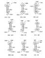
- FIG. 13has five views, labeled A-E, showing an end region of five different flexible bands each having a different tab shape;
- FIG. 14has twelve views, labeled A-L, showing cross sections of different rail clamps contemplated by this disclosure with each of the different rail clamps being attachable to a standard-sized accessory rail of a surgical table;
- FIG. 15has two views, labeled A and B, showing cross sections of different flexible bands contemplated by this disclosure
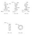
- FIG. 16is a perspective view showing a urology drainage bag attached to a roll-away cart that can be used in the place of a urology bag that is attached to an OR table with the urology bag having an integrated flexible band at its upper opening;
- FIG. 17is a perspective view showing an embodiment having integrated clamps, flexible band, and urology drainage bag arranged for attachment to a pair of accessory rails at the end of an OR table in the direction of the pair of double arrows;
- FIG. 18is a perspective view, similar to FIG. 14 , with the integrated clamps, band, and bag attached to the accessory rails of the OR table and a flap of the drainage bag moved to a position overlying an end region of an OR table mattress;
- FIG. 19is a perspective view showing a user's hands holding rail clamps of an integrated system attached to accessory rails of an OR table and showing a set of double arrows which diagrammatically indicate a squeezing motion by the user's hands to secure the rail clamps to the accessory rails;
- FIG. 20is a perspective view showing a manner of removing a rail clamp from the accessory rail by sliding upper and lower rail clamp portions horizontally in opposite directions along the accessory rail to achieve separation of the rail clamp portions for removal;
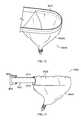
- FIG. 21is a perspective view of an embodiment in which a drainage bag is integrated with a flexible band via heat or adhesive;
- FIG. 22is a perspective view of an embodiment in which a drainage bag is integrated with a flexible band by forming a pocket at a top region of the bag by using adhesive, heat seal, hook-and-loop type fasteners, or sewing, feeding the flexible band through the pocket, and then attaching ends of the flexible band to rail clamps;
- FIG. 23is a perspective view showing an integrated bag and band combination being separated from a pair of rail clamps for disposal;
- FIG. 24is a perspective view showing an embodiment of a rail clamp having a top section with a downwardly extending toothed tab and a bottom section having a channel that accepts the toothed tab, the teeth of the toothed tab being ramped, and a pair of ramped teeth being provided at the upper end of the channel for intermeshing with the teeth of the tab;
- FIG. 25is a side elevation view of a clampless integrated bag and band system showing the band and bag being rotated in the direction of counterclockwise double arrows so that ends of the band catch onto a bottom of the rail standoffs;
- FIG. 26has three views, labeled A-C, showing in view A, an embodiment of an upside down U-shaped rail clamp having an inclined, inwardly projecting flange extending from one of a pair of vertical walls of the rail clamp, showing in view B, the upside down U-shaped rail clamp being moved downwardly onto an accessory rail with the inclined flange contacting an upper left corner region of the accessory clamp, and showing in view C, the upside down U-shaped clamp attached to the accessory rail with the inclined flange extending beneath the accessory rail to retain the rail clamp on the accessory rail;
- FIG. 27is a perspective view showing an embodiment of a rail clamp having a molded clamp body that slips onto an end of an accessory rail and having a threaded knob that threads through a vertical wall of the clamp body and that projects through a hole in a flexible band to engage a vertical surface of an accessory rail to mount the rail clamp and the flexible band to the accessory rail;
- FIG. 28is an end elevation view of the embodiment of FIG. 27 showing the clamp body having stepped upper and lower jaws with a first set of upper and lower shoulders defining upper and lower band receiving grooves adjacent the vertical wall of the clamp body, a second set of upper and lower shoulders defining rail receiving channels that receive the accessory rail, and retention tips adjacent portions of a vertical surface of the accessory rail;
- FIG. 29is an isometric view of a plastic coupler having an elongated post of X-shaped or cross-shaped cross section and a rectangular band receiving portion at the end of the elongated post showing a flexible band attached to the rectangular band receiving portion;
- FIG. 30is a detailed perspective view of the plastic coupler of FIG. 29 showing a urology drainage bag attached to the flexible band that has its ends attached to respective plastic couplers and showing the post of the plastic coupler inserted into a horizontal socket provided in a frame member of an OR table;
- FIG. 31is a perspective view of a flexible band having a tip that is molded to include a rounded end and a through hole and that attaches to the main band member with heat or adhesive;
- FIG. 32is a perspective view of a reusable rail clamp having a lever that can be pushed to permit the flexible band to be detached from the rail clamp;
- FIG. 33is a rear elevation view of the rail clamp of FIG. 32 ;
- FIG. 34is a side elevation view of the rail clamp of FIG. 32 ;
- FIG. 35is a cross-sectional view of the rail clamp of FIG. 32 taken at line 35 - 35 as shown in FIG. 32 showing the reusable rail clamp body having a spring loaded pivotable lever with a projecting pin at its upper end that is received in the through hole of a flexible band to retain the flexible band in place relative to the rail clamp body;
- FIG. 36is a front elevation view of the rail clamp of FIG. 32 ;
- FIG. 37is a cross-sectional view of an end region of the lever shown in FIG. 32 ;
- FIG. 38is a rear elevation view of the end region of FIG. 37 ;
- FIG. 39is a rear elevation view of an alternative end region of the lever shown in FIG. 32 wherein the lever includes a channel extending across the lower end of the lever.
- An illustrative disposable urology drainage bag system 10includes a drainage bag 12 , a flexible support band 14 , a first clamp 16 , and a second clamp 18 as shown in FIG. 1 .
- Drainage bag system 10is configured to be used with a surgical table 20 having accessory rails 22 .
- Drainage bag 12is supported and held open by flexible support band 14 during surgery.
- Flexible support band 14supports drainage bag 12 as shown, for example, in FIG. 1 .
- Clamps 16 , 18are coupled to flexible support band 14 and clamps 16 , 18 clamp on to accessory rails 22 of surgical table 20 to couple drainage bag system 10 to surgical table 20 during surgery.
- drainage bag 12is constructed from a flexible sheet of plastics material.
- Drainage bag 12includes a reservoir portion 24 , a sleeve portion 26 , and a flap 28 as shown in FIG. 1 .
- Reservoir portion 24is situated near and contacts an edge 29 of surgical table 20 as shown in FIG. 1 .
- Sleeve portion 26wraps around flexible support band 14 and couples drainage bag 12 to flexible support band 14 .
- Flap 28extends over surgical table 20 so that fluids are blocked from contact with surgical table 20 .
- Flexible support band 14is operable to support and to hold open reservoir portion 24 of drainage bag 12 as shown in FIG. 1 .
- Flexible support band 14is flexible in the horizontal direction and is semi-rigid in the vertical direction. On account of its flexibility in the horizontal direction, flexible support band 14 is operable to flex in response to a surgeon or other caregiver contacting flexible support band 14 so that the surgeon or caregiver is not blocked from approaching the surgical table 20 by the drainage bag system 10 .
- Flexible support band 14is illustratively made from a disposable or recyclable plastics material. However, in other embodiments, flexible support band 14 may be made from other materials.
- Reservoir portion 24 of drainage bag 12collects and directs fluids toward a waste storage system 30 .
- Reservoir portion 24is coupled to waste storage system 30 by a tube 32 .
- a mesh screen 34is situated in reservoir portion 24 to block solid waste, dropped tools, or other non-liquid items from being directed to waste storage system 30 . In other embodiments, no mesh screen is used.
- Clamps 16 , 18are substantially similar and the following description of clamp 16 applies to clamp 18 .
- Clamp 16includes a clamp body 36 and a threaded knob 38 as shown in FIG. 3 .
- clamp body 36is monolithically formed from a plastics material that is readily disposable or recyclable.
- Threaded knob 38includes a head 40 and a threaded portion 42 as shown, for example, in FIG. 3 .
- Threaded knob 38is illustratively constructed from a plastics material that is readily disposable or recyclable.
- Clamp body 36is illustratively formed to include a beam 44 , an upper jaw 46 , a lower jaw 48 , and a lower platform 50 as shown in FIG. 4 .
- Upper jaw 46extends from a top end 51 of beam 44 .
- Lower jaw 48is coupled to beam 44 by a living hinge 52 defining a jaw axis 48 A shown in FIG. 3 .
- Lower platform 50extends from a bottom end 53 of beam 44 and is formed to include a threaded hole 54 sized to engage with the threaded portion 42 of threaded knob 38 .
- Lower jaw 48is situated between upper jaw 46 and lower platform 50 and an opening 57 is formed between upper jaw 46 and lower jaw 48 to receive accessory rail 22 as shown in FIGS. 4 and 5 .
- Lower jaw 48 of clamp body 36moves between an open position, shown in FIG. 4 , and a closed position shown in FIG. 5 .
- clamp 16When lower jaw 48 is in the open position, clamp 16 is free to slide on to and along accessory rail 22 .
- upper and lower jaws 46 , 48are clamped on to accessory rail 22 as shown in FIG. 5 .
- Lower jaw 48is biased toward the open position by living hinge 52 as suggested in FIG. 4 .
- a userrotates threaded knob 38 so that threaded knob 38 moves through lower platform 50 toward upper jaw 46 as suggested by arrow 38 A in FIGS. 4 and 5 .
- Threaded knob 38engages lower jaw 48 as it moves toward upper jaw 46 and causes lower jaw 48 to pivot about jaw axis 48 A as suggested by arrow 48 P shown in FIGS. 4 and 5 .
- a userrotates the threaded knob 38 to move threaded knob 38 away from upper jaw 46 .
- threaded knob 38is moved away from upper jaw 46 , lower jaw 48 moves away from upper jaw 46 .
- Beam 44 of clamp body 36is formed to include a slot 55 and a protrusion 56 as shown, for example, in FIG. 3 .
- Slot 55is sized to receive flexible support band 14 .
- slot 55is in communication with opening 57 configured to receive accessory rail 22 .
- slot 55may be independent from opening 57 .
- Protrusion 56is configured to be received in a hole 58 formed in flexible support band 14 to locate flexible support band 14 in clamp 16 when flexible support band 14 is received in slot 55 .
- FIG. 6Another embodiment 110 is shown in FIG. 6 in which a flexible band 112 is secured to lower sections or portions 114 of a pair of rail clamps 116 which also have an upper section or portion 118 .
- the upper and lower portions 114 , 118 of the pair of rail clamps 116are separable into two pieces that selectively attach to one another that detach from one another.
- band 112is removed along with the lower section 114 of the rail clamps.
- Clamps 116attach to accessory rails 120 of an OR table or surgical table 122 .
- FIG. 7An embodiment 210 in which a flexible band 212 is detachable from associated rail clamps 216 is shown in FIG. 7 .
- a flexible band 312has its opposite ends integrated with a respective clamp 316 of a pair of rail clamps 316 as shown in the embodiment 310 of FIG. 8 .
- the clamps 316are mounted to accessory rails 320 of a surgical table 322 .
- the flexible band 312has side portions that are squeezed or flexed inwardly toward another in the direction of arrows 313 to snap the clamps 316 off of the accessory rails 320 in the directions of arrows 315 .
- FIG. 9An embodiment 510 in which a rail clamp 516 has a larger, first channel 524 sized to receive an accessory rail (not shown in FIG. 9 ) of a surgical table and a smaller, second channel 526 sized to receive an end of a flexible band 512 is shown in FIG. 9 .
- An end 513 of flexible band 512is arranged for insertion into the second channel 526 .
- the end 513is held in channel 526 by an interference fit in some embodiments.
- end 513is adhered to clamp 516 such as by heat (e.g., RF or sonic welding) or by using an adhesive material (e.g., glue or cement).
- an alternative embodiment 610shown in FIG.
- clamp 616 of FIG. 10is similar to clamp 516 of FIG. 9 except that the structure of the clamp 516 forming channel 526 is omitted in clamp 616 .
- an embodiment 710 of a rail clamp 716has two clamp halves 714 , 718 each of which has a groove 721 that receives upper and lower edge regions 723 , 725 of a flexible band 712 with the flexible band situated in the same channel 724 of the accessory rail clamp 716 that receives an accessory rail (not shown in FIG. 11 ) of a surgical table (not shown in FIG. 11 ) such that a portion of the flexible band 712 will be adjacent the accessory rail.
- an embodiment 810includes a flexible band 812 having a through hole 813 and a rail clamp 816 having a post 817 protruding from a vertical wall 815 of rail clamp 816 .
- Rail clamp 816also has an L-shaped corner locator 819 protruding from the vertical wall 815 .
- a corner 827 of band 812nests within the corner locator 819 and post 817 is received in hole 813 when band 812 is attached to clamp 816 .
- post 817has a slightly enlarged head that snaps through hole 813 when band 812 is being attached to clamp 816 or detached from clamp 816 .
- the end of post 817may be staked or headed to enlarge the end of post 817 by a sufficient amount after band 812 has been attached to permanently attach band 812 to clamp 816 .
- FIG. 13has five views, labeled A-E, showing an end region of five different flexible bands 1012 a - 1012 e each having a different tab shape.
- the topmost view withwill be referred to as the first view of FIG. 13 and the bottommost view will be referred to as the fifth view of FIG. 13 with similar numerical designators from top to bottom of FIG. 13 .
- band 1012 ahas a notch 1013 a along its top edge 1023 a such that a generally square-shaped tab portion 1018 a of band 1012 a is defined next to a necked down portion 1026 a of band 1012 a .
- band 1012 bhas an undercut notch 1013 b along its top edge 1023 b such that a barbed tab portion 1018 b of band 1012 b is defined next to a necked down portion 1026 b of band 1012 b .
- Barbed tab portion 1018 bhas an arcuate upper edge 1019 b .
- band 1012 cis substantially similar to band 412 of FIG. 4 and has a rounded tab 1018 c next to a necked down portion 1026 c .
- Notches 1013 c and 1015 care provided in an upper edge 1023 c and bottom edge 1025 c of band 1012 c to define necked down portion 1026 c .
- Tab 1018 chas a diamond shaped opening 1017 c.
- band 1012 dhas a spade shaped tab 1018 d next to a necked down portion 1026 d .
- Notches 1013 d and 1015 dare provided in an upper edge 1023 d and bottom edge 1025 d of band 1012 d to define necked down portion 1026 d .
- Tab 1018 dhas a somewhat diamond shaped opening 1017 d .
- band 1012 ehas a rounded tab 1018 e next to a necked down portion 1026 e .
- Notches 1013 e and 1015 eare provided in an upper edge 1023 e and bottom edge 1025 e to define necked down portion 1026 e .
- Tab 1018 ehas a horizontal slot 1017 e provided along a longitudinal centerline of band 1012 e.
- FIG. 14has twelve views, labeled A-L, showing cross sections of different rail clamps 1116 A- 1116 L contemplated by this disclosure with each of the different rail clamps being attachable to a standard-sized accessory rail 1100 of a surgical table.
- Clamp 1116 Ahas an upside down U-shaped upper jaw portion 1118 A and an upwardly inclined lower jaw portion 1120 A.
- Clamp 1116 Bhas an upside down V-shaped upper jaw portion 1118 B and a V-shaped lower jaw portion 1120 B.
- Clamp 1116 Chas a downwardly inclined upper jaw portion 1118 C, an upwardly inclined lower jaw portion 1120 C, and a straight vertical wall 1122 C.
- Clamp 1116 Dhas an upside down U-shaped upper jaw portion 1118 D and U-shaped lower jaw portion 1120 D.
- Clamp 1116 Ehas an upside down U-shaped upper jaw portion 1118 E and an L-shaped lower jaw portion 1120 E.
- Clamp 1116 Fhas a downwardly arced upper jaw portion 1118 F and an upwardly arced lower jaw portion 1120 F.
- Clamp 1116 Ghas an upside down L-shaped upper jaw portion 1118 G and an upwardly arced lower jaw portion 1120 G.
- Clamp 1116 Hhas an upside down U-shaped upper jaw portion 1118 H and a V-shaped lower jaw portion 1120 H.
- Clamp 1116 Ihas an upside down L-shaped upper jaw portion 1118 I with a downwardly inclined lip extension 1119 I and an L-shaped lower jaw portion 1120 I with an upwardly inclined lip extension 1121 I.
- Clamp 1116 Jhas an upside down L-shaped upper jaw portion 1118 J with a downwardly inclined lip extension 1119 J and a V-shaped lower jaw portion 1120 J.
- Clamp 1116 Khas a tilted upside down V-shaped upper jaw portion 1118 K and a tilted V-shaped lower jaw portion 1120 K.
- Clamp 1116 Lhas an upside down tilted V-shaped upper jaw portion 1118 L and an L-shaped lower jaw portion 1120 L with an upwardly inclined lip extension 1121 L.
- FIG. 15has two views, labeled A and B, showing cross sections of different flexible bands 1212 A and 1212 B contemplated by this disclosure.
- Band 1212 Ahas an upright solid rectangular cross section.
- Band 1212 Bhas an upright hollow rectangular cross section.
- a urology drainage bag 1300is attached to a roll-away cart 1302 .
- Bag 1300 and cart 1302can be used in the place of a urology bag that is attached to an OR table.
- the cart 1302has a base 1304 supported on a set of corner casters 1306 .
- Cart 1302has a pair of upright A-frames 1308 extending upwardly from base 1304 on opposite side of cart 1302 .
- Urology bag 1300has an integrated flexible band 1312 at its upper opening. Bag 1300 also includes a flap 1301 extending out from band 1312 and configured to overlie an end region of an OR table or table mattress (not shown). Portions of band 1312 attach to the upper ends of A-frames 1308 .
- a drainage hose 1350extends from a bottom of bag 1300 to a fluid collection canister 1352 that is supported by base 1304 . Fluid collected in bag 1300 during surgery drains into hose 1350 through a bottom opening 1310 of bag 1300 A trash receptacle 1354 is also supported by base 1304 .
- an embodiment 1410has integrated clamps 1416 , flexible band 1412 , and urology drainage bag 1400 arranged for attachment to a pair of accessory rails 1420 at the end of an OR table 1422 in the direction of the pair of double arrows 1423 .
- a mesh screen 1425is positioned in drainage bag 1400 to block non-liquids from exiting drainage bag 1400 .
- the integrated clamps 1416 , band 1412 , and bag 1400are attached to the accessory rails 1420 of the OR table 1422 in FIG. 18 .
- a flap 1402 of the drainage bag 1400is shown moved to a position overlying an end region of an OR table mattress 1407 with a transition region 1401 of drainage bag 1400 interconnecting the flap 1402 and main bag portion of bag 1400 .
- a user's handsare holding rail clamps 2216 of an integrated clamp 2216 , band 2212 , and drainage bag 2200 system 2210 in a position for generally simultaneous attachment of the clamps 2216 of the integrated system 2210 to accessory rails 2220 of an OR table 2222 .
- the rail clamps 2216 of the integrated system 2210are squeezed in the direction of arrows 2204 to secure the rail clamps 2216 to the accessory rails 2220 .
- FIG. 20illustrates the general concept of removing a rail clamp 2816 from an accessory rail 2820 by sliding lower and upper rail clamp 2814 , 2818 portions horizontally in opposite directions, indicated by arrows 2802 , along the accessory rail 2820 to achieve separation of the rail clamp portions 2814 , 2818 for removal.
- FIG. 21An embodiment 3010 in which a drainage bag 3000 is integrated with a flexible band 3012 via heat (i.e., RF or sonic welding) or adhesive material (i.e., glue or cement) is shown in FIG. 21 .
- An embodiment 3110 in which a drainage bag 3100 is integrated with a flexible band 3112 by forming a pocket 3102 at a top region of the bag by using adhesive, heat seal, hook-and-loop type fasteners, or sewing, and then feeding the flexible band 3112 through the pocket 3102is shown in FIG. 22 .
- ends 3113 of the flexible band 3112are attached to rail clamps 3116 , only one of which is shown in FIG. 22 .
- an integrated bag 3300 and band 3312 combinationis separated from a pair of rail clamps 3316 for disposal.
- a rail clamp 3416has a top section 3418 with a downwardly extending toothed tab 3450 and a bottom section 3414 having a channel 3452 that accepts the toothed tab 3450 .
- Teeth 3456 of the toothed tab 3450are ramped.
- a pair of ramped teeth 3458are provided at the upper end of the channel 3452 for intermeshing with the teeth of the tab 3450 as shown best in FIG. 24 .
- Rail clamp 3416is clamped onto an accessory rail 3420 by inserting the toothed tab 3450 into an upper region of the channel 3452 and then vertical squeezing portions 3414 , 3418 together.
- portions 3414 , 3418 of clamp 3416are slid horizontally in opposite directions along the accessory rail 3420 until portions 3414 , 3418 are slid horizontally by a sufficient amount to be separated from one another.
- Each of portions 3414 , 3418 of clamp 3416has a finger tab 3464 that can be pressed or gripped by a user to facilitate the horizontal sliding movement of portions 3414 , 3418 .
- a clampless system 4010includes an integrated bag 4000 and band 4012 .
- ends 4013 of band 4012are inserted (with the bag 4000 attached) generally vertically downwardly between the OR table 4022 and the accessory rails 4020 in front of standoffs 4021 of the accessory rail 4020 .
- the band 4012 and bag 4000are rotated in the direction of counterclockwise double arrows 4002 so that ends 4013 of the band 4012 catch onto a bottom of the rail standoffs 4021 . Further rotation of the band 4012 and bag 4000 thereafter cause a looped portion 4015 of the band 4012 to rest atop the accessory rail 4020 with a majority of the flexible band 4012 being held in a horizontal orientation.
- an upper edge 4017 of each end portion 4013 of band 4012has a notch 4019 that receives the rail standoff 4021 when the system 4010 is mounted to OR table 4022 .
- a distal tab 4018 defined to the right of notch 4019 in FIG. 25prevents system 4010 from sliding horizontally off of the accessory rails 4020 when system 4010 is in use during a surgical procedure.
- an upside down U-shaped rail clamp 5916has an inclined, inwardly projecting flange 5902 extending from one of a pair of vertical walls 5904 of the rail clamp.
- the inclined flange 5902first contacts an upper left corner region of the accessory clamp 5920 (see FIG. 26B ). Further downward movement of clamp 5916 over accessory rail 5920 causes flange 5902 and the associated wall 5904 to flex outwardly.
- the inclined flange 5902extends beneath the accessory rail 5920 to retain the rail clamp 5916 on the accessory rail 5920 .
- a rail clamp 7616has a molded clamp body 7602 that slips onto an end of an accessory rail 7620 and has a threaded knob 7604 that threads through a vertical wall 7606 of the clamp body 7602 .
- the tip of threaded knob 7604projects through a hole 7613 (shown in FIG. 28 in phantom) in a flexible band 7612 to engage a vertical surface of an accessory rail 7620 to mount the rail clamp 7616 and the flexible band 7612 to the accessory rail 7620 .
- Clamp body 7602has stepped lower and upper jaws 7614 , 7618 with a first set of upper and lower shoulders 7650 (see FIG.
- a drainage bagcouples to flexible band 7612 .
- Rail clamp 7616is attached to an accessory rail 7620 of an OR table (not shown).
- Rail clamps 7616 and flexible band 7612are attached to accessory rails 7620 of an OR table (not shown) and arrows 7660 show the rotational direction of tightening the threaded knobs 7604 so that knob 7604 is turned away from the user to secure the rail clamps 7616 to the rails 7620 .
- the patient's left clamp 7616has a clockwise thread and the patient's right clamp 7616 as a counterclockwise thread.
- a plastic coupler 8402has an elongated post 8404 of X-shaped or cross-shaped cross section and a rectangular band receiving portion 8406 at the end of the elongated post 8404 .
- a flexible bandattached to the rectangular band receiving portion 8406 via a press fit into a cavity 8408 of portion 8406 .
- a urology drainage bag 8400attaches to the flexible band 8412 that has its ends attached to respective plastic couplers 8402 .
- the post 8404 of the plastic coupler 8402is sized for press fit insertion into a horizontal socket 8490 provided in a frame member 8492 of an OR table 8422 as shown best in FIG. 30 .
- a flexible band 9612has separate tips 9613 that are molded to include a rounded end 9615 and a through hole 9617 . Tips 9613 have band receiving pockets 9650 sized to receive the main band member with a press fit. In alternative embodiments, heat or adhesive is used to couple the main band member to tips 9613 .
- a reusable rail clamp 9716has a lever 9702 attached to a main clamp body 9704 .
- Lever 9702can be pushed to permit a flexible band 9712 to be detached from the rail clamp 9716 .
- Clamp 9716has a vertically oriented threaded knob 9706 that can be tightened against the bottom of an accessory rail (not shown) to retain clamp 9716 on the rail.
- Lever 9702has a protrusion 9708 (see FIG. 35 ) that is received in a hole 9713 of band 9712 to retain band 9712 relative to main body 9704 of clamp 9716 .
- Lever 9702can have a pocket 9740 (see FIG.
- FIG. 35shows cross sections of reusable rail 9716 with clamp body 9704 having a spring 9977 biasing pivotable lever 9702 to a locking position in which a projecting pin 9708 at its upper end is received in the through hole 9713 of flexible band 9712 to retain the flexible band 9712 in place relative to the rail clamp body 9704 .
Landscapes
- Health & Medical Sciences (AREA)
- Engineering & Computer Science (AREA)
- Biomedical Technology (AREA)
- Life Sciences & Earth Sciences (AREA)
- Animal Behavior & Ethology (AREA)
- General Health & Medical Sciences (AREA)
- Public Health (AREA)
- Veterinary Medicine (AREA)
- Accommodation For Nursing Or Treatment Tables (AREA)
Abstract
Description
Claims (20)
Priority Applications (1)
| Application Number | Priority Date | Filing Date | Title |
|---|---|---|---|
| US13/177,609US8833707B2 (en) | 2010-07-15 | 2011-07-07 | Disposable urology drainage bag |
Applications Claiming Priority (2)
| Application Number | Priority Date | Filing Date | Title |
|---|---|---|---|
| US36474310P | 2010-07-15 | 2010-07-15 | |
| US13/177,609US8833707B2 (en) | 2010-07-15 | 2011-07-07 | Disposable urology drainage bag |
Publications (2)
| Publication Number | Publication Date |
|---|---|
| US20120014621A1 US20120014621A1 (en) | 2012-01-19 |
| US8833707B2true US8833707B2 (en) | 2014-09-16 |
Family
ID=44658589
Family Applications (1)
| Application Number | Title | Priority Date | Filing Date |
|---|---|---|---|
| US13/177,609Active2031-10-02US8833707B2 (en) | 2010-07-15 | 2011-07-07 | Disposable urology drainage bag |
Country Status (2)
| Country | Link |
|---|---|
| US (1) | US8833707B2 (en) |
| EP (2) | EP2724700B1 (en) |
Cited By (25)
| Publication number | Priority date | Publication date | Assignee | Title |
|---|---|---|---|---|
| US20160136028A1 (en)* | 2013-08-08 | 2016-05-19 | MAQUET GmbH | Clamping claw for mounting on a sliding rail of an operating table |
| US20170135901A1 (en)* | 2015-11-12 | 2017-05-18 | Scalpas Llc | Bottle support and protective collar |
| US9750657B2 (en) | 2013-10-30 | 2017-09-05 | Allen Medical Systems, Inc. | Accessory flat-top panel for use with surgical tables |
| US9814640B1 (en)* | 2014-10-31 | 2017-11-14 | Space Technology Research LLC | Robotic arm bed assist |
| US9951904B2 (en) | 2015-03-24 | 2018-04-24 | Stryker Corporation | Rotatable seat clamps for rail clamp |
| US9968503B2 (en) | 2012-04-16 | 2018-05-15 | Allen Medical Systems, Inc. | Dual column surgical table having a single-handle unlock for table rotation |
| US20180168899A1 (en)* | 2016-12-15 | 2018-06-21 | Hill-Rom Services, Inc. | Patient bed with support assist |
| US10363189B2 (en) | 2015-10-23 | 2019-07-30 | Allen Medical Systems, Inc. | Surgical patient support for accommodating lateral-to-prone patient positioning |
| US10478364B2 (en) | 2014-03-10 | 2019-11-19 | Stryker Corporation | Limb positioning system |
| US10492973B2 (en) | 2015-01-05 | 2019-12-03 | Allen Medical Systems, Inc. | Dual modality prone spine patient support apparatuses |
| US10548793B2 (en) | 2016-06-14 | 2020-02-04 | Allen Medical Systems, Inc. | Pinless loading for spine table |
| US10561559B2 (en) | 2015-10-23 | 2020-02-18 | Allen Medical Systems, Inc. | Surgical patient support system and method for lateral-to-prone support of a patient during spine surgery |
| USD878836S1 (en) | 2017-08-17 | 2020-03-24 | Stryker Corp. | Table extender |
| US10828218B2 (en) | 2015-06-05 | 2020-11-10 | Stryker Corporation | Surgical table and accessories to facilitate hip arthroscopy |
| US10952914B1 (en)* | 2017-02-17 | 2021-03-23 | Kyra Medical, Inc | Clamp apparatus for attaching a surgical accessory to a mounting rail |
| US11202731B2 (en) | 2018-02-28 | 2021-12-21 | Allen Medical Systems, Inc. | Surgical patient support and methods thereof |
| US11213448B2 (en) | 2017-07-31 | 2022-01-04 | Allen Medical Systems, Inc. | Rotation lockout for surgical support |
| US11471354B2 (en) | 2018-08-30 | 2022-10-18 | Allen Medical Systems, Inc. | Patient support with selectable pivot |
| US11510805B2 (en) | 2017-02-06 | 2022-11-29 | Stryker Corp. | Anatomical gripping system for gripping the leg and foot of a patient when effecting hip distraction and/or when effecting leg positioning |
| US11559455B2 (en) | 2017-02-06 | 2023-01-24 | Stryker Corp. | Distraction frame for effecting hip distraction |
| US11564855B2 (en) | 2020-09-28 | 2023-01-31 | Stryker Corporation | Systems and methods for supporting and stabilizing a patient during hip distraction |
| US11684532B2 (en) | 2017-02-06 | 2023-06-27 | Stryker Corp. | Method and apparatus for supporting and stabilizing a patient during hip distraction |
| US20240148587A1 (en)* | 2022-11-07 | 2024-05-09 | Frederick H. Sklar | Base station assembly for an operating room table |
| US12280000B2 (en) | 2016-09-19 | 2025-04-22 | Kyra Medical, Inc | Limb holder allowing distal actuation along non-linear paths of actuation |
| NL2039607A (en)* | 2024-01-26 | 2025-08-06 | Kyra Medical Inc | Means of attaching instruments to a surgical table |
Families Citing this family (8)
| Publication number | Priority date | Publication date | Assignee | Title |
|---|---|---|---|---|
| WO2013158657A1 (en)* | 2012-04-18 | 2013-10-24 | Volcano Corporation | Integrated support structures for mobile medical systems |
| CN102846445A (en)* | 2012-10-09 | 2013-01-02 | 迈柯唯医疗设备(苏州)有限公司 | Orientation heavy load calipers |
| CA2936677A1 (en)* | 2014-01-13 | 2015-07-16 | Ferno-Washington, Inc. | Accessory clamp for emergency cots |
| CN107753234A (en)* | 2017-11-10 | 2018-03-06 | 威海威高骨科手术机器人有限公司 | Robot interfacing part |
| US20220079827A1 (en)* | 2020-09-15 | 2022-03-17 | Vimadri, LLC | Fluid collection device, related apparatus and method of using the same |
| US20220160567A1 (en)* | 2020-11-23 | 2022-05-26 | Domico Med-Device, LLC. | Table pad and fluid collection cover therefor and method of protecting a table pad and surroundings against fluid contamination |
| CN112674981A (en)* | 2021-01-12 | 2021-04-20 | 青岛市妇女儿童医院 | Blood loss fixing device in obstetrical surgery |
| CN113230079B (en)* | 2021-06-22 | 2022-08-26 | 中国人民解放军空军军医大学 | Rectal cancer operation position pad |
Citations (81)
| Publication number | Priority date | Publication date | Assignee | Title |
|---|---|---|---|---|
| US2509086A (en) | 1948-08-10 | 1950-05-23 | Eaton Appliance Corp | Headrest for operating tables |
| US2932873A (en)* | 1958-06-09 | 1960-04-19 | Shampaine Company | Clamp |
| US2935286A (en) | 1956-01-27 | 1960-05-03 | Parsons Jim Skelt | Infusion standard |
| US2945731A (en)* | 1959-07-23 | 1960-07-19 | David A Tutrone | Surgical drainage attachment |
| US3046072A (en)* | 1960-01-21 | 1962-07-24 | Shampaine Ind Inc | Accessory supports for surgical operating tables and the like |
| US3099441A (en) | 1959-12-29 | 1963-07-30 | Ries Mfg Company | Surgical device |
| US3188079A (en) | 1962-04-05 | 1965-06-08 | American Sterilizer Co | Surgical headrest |
| US3386444A (en)* | 1966-11-07 | 1968-06-04 | Ritter Pfaudler Corp | Surgical drain bag and support therefor |
| US3828377A (en) | 1973-02-02 | 1974-08-13 | G Fary | Adjustable body rest |
| US3947686A (en) | 1974-04-25 | 1976-03-30 | The Babcock & Wilcox Co. | Graphite composite X-ray transparent patient support |
| US4018412A (en) | 1975-10-14 | 1977-04-19 | Kees Surgical Specialty Company | Bracket for an operating table |
| US4054282A (en) | 1976-11-19 | 1977-10-18 | Louis O. Scheu, Jr. | Auxiliary operating table for hand surgery and the like |
| US4108426A (en) | 1978-01-26 | 1978-08-22 | Siemens Aktiengesellschaft | Device for holding the head of a patient |
| US4139917A (en) | 1977-10-17 | 1979-02-20 | Loel Fenwick | Labor, delivery and patient care bed |
| US4143652A (en) | 1976-01-29 | 1979-03-13 | Hans Meier | Surgical retaining device |
| US4221371A (en) | 1977-12-30 | 1980-09-09 | Siemens Aktiengesellschaft | Urological examination table |
| US4225125A (en) | 1977-04-28 | 1980-09-30 | Matburn (Holdings) Limited | Operation table |
| US4355631A (en) | 1981-03-19 | 1982-10-26 | Minnesota Scientific, Inc. | Surgical retractor apparatus with improved clamping device |
| US4378794A (en) | 1981-01-07 | 1983-04-05 | The Kendall Company | Surgical drape |
| US4383351A (en) | 1981-10-23 | 1983-05-17 | Loel Fenwick | Universal clamp |
| US4414968A (en) | 1981-05-29 | 1983-11-15 | Amin Shailesh R | Surgical drape |
| US4474364A (en) | 1982-11-29 | 1984-10-02 | American Sterilizer Company | Surgical table |
| US4484911A (en) | 1982-09-29 | 1984-11-27 | Berlin Richard B | Cannula and clamp device |
| US4487523A (en) | 1981-12-31 | 1984-12-11 | American Sterilizer Company | Accessory clamp for abductor bar |
| US4506872A (en) | 1982-09-29 | 1985-03-26 | Siemens Aktiengesellschaft | Device for mounting accessories on a patient support apparatus |
| US4526355A (en) | 1982-09-29 | 1985-07-02 | Moore Robert R | Arthroscopic leg holder |
| US4583725A (en) | 1985-03-05 | 1986-04-22 | Arnold Roger D | Patient support frame for posterior lumbar laminectomy |
| US4671728A (en) | 1985-07-11 | 1987-06-09 | Applied Power, Inc. | Hydraulic system for a mobile transport vehicle that supports and positions a load relative to a docking structure |
| US4729535A (en) | 1986-12-09 | 1988-03-08 | Frazier Stanley J | Apparatus for supporting a cooking device |
| US4796846A (en) | 1987-06-01 | 1989-01-10 | Automated Medical Products, Corporation | Retaining device for a surgical instrument |
| US4840363A (en) | 1981-05-27 | 1989-06-20 | Mcconnell Bernard E | Telescoping, sterile upright support assembly |
| US4852840A (en) | 1988-09-06 | 1989-08-01 | Marks Dale H | Clamp for mounting a device to a tubular |
| US4901963A (en) | 1985-06-20 | 1990-02-20 | Universal Consolidated Methods, Inc. | Adjustable clamp |
| US4901964A (en) | 1985-01-22 | 1990-02-20 | Mcconnell Bernard E | Rail clamp |
| US4923187A (en) | 1989-03-10 | 1990-05-08 | Avec Scientific Utility Corporation | Radiolucent iliac crest support frame |
| US4971037A (en) | 1988-09-19 | 1990-11-20 | Pilling Co. | Surgical retractor support |
| US4989848A (en) | 1981-12-21 | 1991-02-05 | American Sterilizer Company | Apparatus for adjusting the position of the upper body support of an orthopedic table |
| US5027832A (en) | 1990-01-05 | 1991-07-02 | Williams Jr John W | Surgical drape support apparatus |
| US5078705A (en)* | 1991-02-05 | 1992-01-07 | Diasonics, Inc. | Drain bag apparatus |
| US5088706A (en) | 1990-08-30 | 1992-02-18 | Jackson Roger P | Spinal surgery table |
| US5108213A (en) | 1991-03-22 | 1992-04-28 | Edgewater Medical Equipment Systems, Inc. | Clamping assembly |
| US5121892A (en) | 1991-02-15 | 1992-06-16 | Herzog Kenneth J | Pivoting rail clamp |
| US5131106A (en) | 1990-08-30 | 1992-07-21 | Jackson Roger P | Spinal surgery table |
| US5135210A (en) | 1989-05-01 | 1992-08-04 | Michelson Gary K | Surgical armboard attachment device |
| US5161544A (en) | 1990-03-14 | 1992-11-10 | Johnson & Johnson Medical, Inc. | Surgical drape having 360 degree fluid control |
| US5276927A (en) | 1992-09-21 | 1994-01-11 | Ohio Medical Instrument Co. | Radiolucent head support |
| US5279603A (en) | 1990-11-20 | 1994-01-18 | Picker International, Inc. | Collapsible urology drain pan assembly with retention mechanism |
| US5287575A (en) | 1992-11-09 | 1994-02-22 | Allen Medical Systems | Hand table |
| US5320444A (en) | 1993-01-22 | 1994-06-14 | Bookwalter John R | Enclosed surgical apparatus clamp |
| US5326059A (en)* | 1992-12-23 | 1994-07-05 | Pryor Products | Quick clamping system |
| US5388593A (en) | 1991-11-04 | 1995-02-14 | Marshfield Medical Research & Education Foundation | Surgical drape for endoscopy |
| US5400772A (en) | 1991-05-24 | 1995-03-28 | Minnesota Scientific, Inc. | Surgical retractor apparatus with improved clamping device |
| US5444882A (en) | 1990-09-17 | 1995-08-29 | Orthopedic Systems, Inc. | Spinal surgery table |
| US5538215A (en) | 1994-11-15 | 1996-07-23 | Midmark Corporation | Siderail socket |
| US5581830A (en)* | 1993-05-21 | 1996-12-10 | U.S. Philips Corporation | Urological examination apparatus |
| US5613254A (en) | 1994-12-02 | 1997-03-25 | Clayman; Ralph V. | Radiolucent table for supporting patients during medical procedures |
| US5658315A (en) | 1994-02-23 | 1997-08-19 | Orthopedic Systems, Inc. | Apparatus and method for lower limb traction |
| US5701991A (en) | 1996-02-06 | 1997-12-30 | Hi-Speed Checkweigher Co., Inc. | Clamping mechanism |
| US5741210A (en) | 1995-10-10 | 1998-04-21 | Minnesota Scientific, Inc. | Clamping device for a surgical retractor |
| US5758374A (en) | 1996-05-20 | 1998-06-02 | Ronci; Samuel | Portable table assembly |
| US5836026A (en) | 1997-05-22 | 1998-11-17 | Reed; Michael C. | Orthopedic trapeze with self-locking rotatable mechanism |
| US5836559A (en) | 1997-05-23 | 1998-11-17 | Ronci; Samuel | Clamp for securing a pole to a stationary object |
| US5926876A (en) | 1996-11-19 | 1999-07-27 | Compacta International, Ltd. | Surgical operating table accessory for shoulder procedures |
| US6023800A (en)* | 1997-05-09 | 2000-02-15 | Midmark Corporation | Removable accessory for a surgical table |
| US6120397A (en) | 1998-01-21 | 2000-09-19 | Indian Industries, Inc. | Table tennis table top with pivotal legs |
| US6260220B1 (en) | 1997-02-13 | 2001-07-17 | Orthopedic Systems, Inc. | Surgical table for lateral procedures |
| US6382576B1 (en) | 1999-06-08 | 2002-05-07 | Hill-Rom Services, Inc. | Clamping apparatus |
| US20020061225A1 (en) | 2000-03-28 | 2002-05-23 | Boucher Michael M. | Socket and rail clamp apparatus |
| US6490737B1 (en) | 1998-05-19 | 2002-12-10 | Dupaco, Inc | Protective cushion and cooperatively engageable helmet casing for anesthetized patient |
| US6598275B1 (en) | 2001-03-12 | 2003-07-29 | Steris, Inc. | Low shadow radiolucent surgical table, clamp systems, and accessories therefore |
| US6663055B2 (en) | 2000-03-15 | 2003-12-16 | The Or Group, Inc. | Armboard assembly |
| US6691350B2 (en) | 1999-12-13 | 2004-02-17 | Hill-Rom Services, Inc. | Accessories for a patient support apparatus |
| US6754923B2 (en) | 1997-11-07 | 2004-06-29 | Hill-Rom Services, Inc. | Leg section support for a surgical table |
| US20040144905A1 (en)* | 2001-09-27 | 2004-07-29 | Frank Ropertz | Fastening block for mounting objects on a profiled rail |
| WO2005020819A1 (en) | 2003-08-28 | 2005-03-10 | Oncolog Medical Qa Ab | Patient repositioning device and method |
| US7096871B2 (en) | 2002-09-05 | 2006-08-29 | Microtek Medical, Inc. | Surgical drape having a fluid collection pouch with an inflatable rim |
| US7096870B2 (en) | 2004-09-30 | 2006-08-29 | Lonnie Jay Lamprich | Disposable sterile surgical drape and attached instruments |
| US20060255220A1 (en) | 2004-11-10 | 2006-11-16 | Skripps Thomas K | Accessory rail clamp with latch and lock mechanisms |
| US7299803B2 (en) | 2000-10-09 | 2007-11-27 | Ams Research Corporation | Pelvic surgery drape |
| US7610918B2 (en) | 2005-07-28 | 2009-11-03 | Kimberly-Clark Worldwide, Inc. | Surgical drape with an integral underbuttocks portion |
| US7690380B2 (en) | 2002-09-05 | 2010-04-06 | Ecolab Inc. | Surgical drape having a fluid collection pouch with an inflatable rim |
Family Cites Families (5)
| Publication number | Priority date | Publication date | Assignee | Title |
|---|---|---|---|---|
| CA931130A (en)* | 1969-10-04 | 1973-07-31 | Itoh Akira | Cabtyre cord hangers for hoist |
| US5362021A (en)* | 1992-05-11 | 1994-11-08 | Phillips Medical Group, Inc. | Multi-adjustable surgical tray apparatus |
| US5871189A (en)* | 1996-03-05 | 1999-02-16 | Hoftman; Moshe | O.R./anesthesia/yankauer holder |
| US5960522A (en)* | 1997-05-21 | 1999-10-05 | Micron Electronics, Inc. | Ribbon cable alligator clamp |
| DE10200755B4 (en)* | 2002-01-10 | 2011-07-07 | EXPRO Kunststoffverarbeitungs GmbH, 97337 | clamping rail |
- 2011
- 2011-07-07USUS13/177,609patent/US8833707B2/enactiveActive
- 2011-07-14EPEP13195374.7Apatent/EP2724700B1/ennot_activeNot-in-force
- 2011-07-14EPEP11174028.8Apatent/EP2407139B1/enactiveActive
Patent Citations (86)
| Publication number | Priority date | Publication date | Assignee | Title |
|---|---|---|---|---|
| US2509086A (en) | 1948-08-10 | 1950-05-23 | Eaton Appliance Corp | Headrest for operating tables |
| US2935286A (en) | 1956-01-27 | 1960-05-03 | Parsons Jim Skelt | Infusion standard |
| US2932873A (en)* | 1958-06-09 | 1960-04-19 | Shampaine Company | Clamp |
| US2945731A (en)* | 1959-07-23 | 1960-07-19 | David A Tutrone | Surgical drainage attachment |
| US3099441A (en) | 1959-12-29 | 1963-07-30 | Ries Mfg Company | Surgical device |
| US3046072A (en)* | 1960-01-21 | 1962-07-24 | Shampaine Ind Inc | Accessory supports for surgical operating tables and the like |
| US3188079A (en) | 1962-04-05 | 1965-06-08 | American Sterilizer Co | Surgical headrest |
| US3386444A (en)* | 1966-11-07 | 1968-06-04 | Ritter Pfaudler Corp | Surgical drain bag and support therefor |
| US3828377A (en) | 1973-02-02 | 1974-08-13 | G Fary | Adjustable body rest |
| US3947686A (en) | 1974-04-25 | 1976-03-30 | The Babcock & Wilcox Co. | Graphite composite X-ray transparent patient support |
| US4018412A (en) | 1975-10-14 | 1977-04-19 | Kees Surgical Specialty Company | Bracket for an operating table |
| US4143652A (en) | 1976-01-29 | 1979-03-13 | Hans Meier | Surgical retaining device |
| US4054282A (en) | 1976-11-19 | 1977-10-18 | Louis O. Scheu, Jr. | Auxiliary operating table for hand surgery and the like |
| US4225125A (en) | 1977-04-28 | 1980-09-30 | Matburn (Holdings) Limited | Operation table |
| US4139917A (en) | 1977-10-17 | 1979-02-20 | Loel Fenwick | Labor, delivery and patient care bed |
| US4221371A (en) | 1977-12-30 | 1980-09-09 | Siemens Aktiengesellschaft | Urological examination table |
| US4108426A (en) | 1978-01-26 | 1978-08-22 | Siemens Aktiengesellschaft | Device for holding the head of a patient |
| US4378794A (en) | 1981-01-07 | 1983-04-05 | The Kendall Company | Surgical drape |
| US4355631A (en) | 1981-03-19 | 1982-10-26 | Minnesota Scientific, Inc. | Surgical retractor apparatus with improved clamping device |
| US4840363A (en) | 1981-05-27 | 1989-06-20 | Mcconnell Bernard E | Telescoping, sterile upright support assembly |
| US4414968A (en) | 1981-05-29 | 1983-11-15 | Amin Shailesh R | Surgical drape |
| US4383351A (en) | 1981-10-23 | 1983-05-17 | Loel Fenwick | Universal clamp |
| US4989848A (en) | 1981-12-21 | 1991-02-05 | American Sterilizer Company | Apparatus for adjusting the position of the upper body support of an orthopedic table |
| US4487523A (en) | 1981-12-31 | 1984-12-11 | American Sterilizer Company | Accessory clamp for abductor bar |
| US4526355A (en) | 1982-09-29 | 1985-07-02 | Moore Robert R | Arthroscopic leg holder |
| US4484911A (en) | 1982-09-29 | 1984-11-27 | Berlin Richard B | Cannula and clamp device |
| US4506872A (en) | 1982-09-29 | 1985-03-26 | Siemens Aktiengesellschaft | Device for mounting accessories on a patient support apparatus |
| US4474364A (en) | 1982-11-29 | 1984-10-02 | American Sterilizer Company | Surgical table |
| US4901964A (en) | 1985-01-22 | 1990-02-20 | Mcconnell Bernard E | Rail clamp |
| US4583725A (en) | 1985-03-05 | 1986-04-22 | Arnold Roger D | Patient support frame for posterior lumbar laminectomy |
| US4901963A (en) | 1985-06-20 | 1990-02-20 | Universal Consolidated Methods, Inc. | Adjustable clamp |
| US4671728A (en) | 1985-07-11 | 1987-06-09 | Applied Power, Inc. | Hydraulic system for a mobile transport vehicle that supports and positions a load relative to a docking structure |
| US4729535A (en) | 1986-12-09 | 1988-03-08 | Frazier Stanley J | Apparatus for supporting a cooking device |
| US4796846A (en) | 1987-06-01 | 1989-01-10 | Automated Medical Products, Corporation | Retaining device for a surgical instrument |
| US4852840A (en) | 1988-09-06 | 1989-08-01 | Marks Dale H | Clamp for mounting a device to a tubular |
| US4971037A (en) | 1988-09-19 | 1990-11-20 | Pilling Co. | Surgical retractor support |
| US4923187A (en) | 1989-03-10 | 1990-05-08 | Avec Scientific Utility Corporation | Radiolucent iliac crest support frame |
| US5135210A (en) | 1989-05-01 | 1992-08-04 | Michelson Gary K | Surgical armboard attachment device |
| US5027832A (en) | 1990-01-05 | 1991-07-02 | Williams Jr John W | Surgical drape support apparatus |
| US5161544A (en) | 1990-03-14 | 1992-11-10 | Johnson & Johnson Medical, Inc. | Surgical drape having 360 degree fluid control |
| US5131106A (en) | 1990-08-30 | 1992-07-21 | Jackson Roger P | Spinal surgery table |
| US5088706A (en) | 1990-08-30 | 1992-02-18 | Jackson Roger P | Spinal surgery table |
| US5444882A (en) | 1990-09-17 | 1995-08-29 | Orthopedic Systems, Inc. | Spinal surgery table |
| US5279603A (en) | 1990-11-20 | 1994-01-18 | Picker International, Inc. | Collapsible urology drain pan assembly with retention mechanism |
| US5078705A (en)* | 1991-02-05 | 1992-01-07 | Diasonics, Inc. | Drain bag apparatus |
| US5121892A (en) | 1991-02-15 | 1992-06-16 | Herzog Kenneth J | Pivoting rail clamp |
| US5108213A (en) | 1991-03-22 | 1992-04-28 | Edgewater Medical Equipment Systems, Inc. | Clamping assembly |
| US5400772A (en) | 1991-05-24 | 1995-03-28 | Minnesota Scientific, Inc. | Surgical retractor apparatus with improved clamping device |
| US5388593A (en) | 1991-11-04 | 1995-02-14 | Marshfield Medical Research & Education Foundation | Surgical drape for endoscopy |
| US5276927A (en) | 1992-09-21 | 1994-01-11 | Ohio Medical Instrument Co. | Radiolucent head support |
| US5287575A (en) | 1992-11-09 | 1994-02-22 | Allen Medical Systems | Hand table |
| US5326059A (en)* | 1992-12-23 | 1994-07-05 | Pryor Products | Quick clamping system |
| US5320444A (en) | 1993-01-22 | 1994-06-14 | Bookwalter John R | Enclosed surgical apparatus clamp |
| US5581830A (en)* | 1993-05-21 | 1996-12-10 | U.S. Philips Corporation | Urological examination apparatus |
| US5658315A (en) | 1994-02-23 | 1997-08-19 | Orthopedic Systems, Inc. | Apparatus and method for lower limb traction |
| US5538215A (en) | 1994-11-15 | 1996-07-23 | Midmark Corporation | Siderail socket |
| US5613254A (en) | 1994-12-02 | 1997-03-25 | Clayman; Ralph V. | Radiolucent table for supporting patients during medical procedures |
| US5741210A (en) | 1995-10-10 | 1998-04-21 | Minnesota Scientific, Inc. | Clamping device for a surgical retractor |
| US5701991A (en) | 1996-02-06 | 1997-12-30 | Hi-Speed Checkweigher Co., Inc. | Clamping mechanism |
| US5758374A (en) | 1996-05-20 | 1998-06-02 | Ronci; Samuel | Portable table assembly |
| US5926876A (en) | 1996-11-19 | 1999-07-27 | Compacta International, Ltd. | Surgical operating table accessory for shoulder procedures |
| US6260220B1 (en) | 1997-02-13 | 2001-07-17 | Orthopedic Systems, Inc. | Surgical table for lateral procedures |
| US6023800A (en)* | 1997-05-09 | 2000-02-15 | Midmark Corporation | Removable accessory for a surgical table |
| US5836026A (en) | 1997-05-22 | 1998-11-17 | Reed; Michael C. | Orthopedic trapeze with self-locking rotatable mechanism |
| US5836559A (en) | 1997-05-23 | 1998-11-17 | Ronci; Samuel | Clamp for securing a pole to a stationary object |
| US6754923B2 (en) | 1997-11-07 | 2004-06-29 | Hill-Rom Services, Inc. | Leg section support for a surgical table |
| US6120397A (en) | 1998-01-21 | 2000-09-19 | Indian Industries, Inc. | Table tennis table top with pivotal legs |
| US6490737B1 (en) | 1998-05-19 | 2002-12-10 | Dupaco, Inc | Protective cushion and cooperatively engageable helmet casing for anesthetized patient |
| US6382576B1 (en) | 1999-06-08 | 2002-05-07 | Hill-Rom Services, Inc. | Clamping apparatus |
| US6691350B2 (en) | 1999-12-13 | 2004-02-17 | Hill-Rom Services, Inc. | Accessories for a patient support apparatus |
| US20040123389A1 (en) | 2000-03-15 | 2004-07-01 | Michael Boucher | Armboard assembly |
| US6663055B2 (en) | 2000-03-15 | 2003-12-16 | The Or Group, Inc. | Armboard assembly |
| US20020061225A1 (en) | 2000-03-28 | 2002-05-23 | Boucher Michael M. | Socket and rail clamp apparatus |
| US6622980B2 (en) | 2000-03-28 | 2003-09-23 | Hill-Rom Services, Inc. | Socket and rail clamp apparatus |
| US7299803B2 (en) | 2000-10-09 | 2007-11-27 | Ams Research Corporation | Pelvic surgery drape |
| US6598275B1 (en) | 2001-03-12 | 2003-07-29 | Steris, Inc. | Low shadow radiolucent surgical table, clamp systems, and accessories therefore |
| US20040144905A1 (en)* | 2001-09-27 | 2004-07-29 | Frank Ropertz | Fastening block for mounting objects on a profiled rail |
| US7096871B2 (en) | 2002-09-05 | 2006-08-29 | Microtek Medical, Inc. | Surgical drape having a fluid collection pouch with an inflatable rim |
| US7690380B2 (en) | 2002-09-05 | 2010-04-06 | Ecolab Inc. | Surgical drape having a fluid collection pouch with an inflatable rim |
| US20100137820A1 (en)* | 2002-09-05 | 2010-06-03 | Ecolab Inc. | Surgical drape having a fluid collection pouch with an inflatable rim |
| US8020561B2 (en) | 2002-09-05 | 2011-09-20 | Microtek Medical, Inc. | Surgical drape having a fluid collection pouch with an inflatable rim |
| WO2005020819A1 (en) | 2003-08-28 | 2005-03-10 | Oncolog Medical Qa Ab | Patient repositioning device and method |
| US7096870B2 (en) | 2004-09-30 | 2006-08-29 | Lonnie Jay Lamprich | Disposable sterile surgical drape and attached instruments |
| US20060255220A1 (en) | 2004-11-10 | 2006-11-16 | Skripps Thomas K | Accessory rail clamp with latch and lock mechanisms |
| US7520007B2 (en) | 2004-11-10 | 2009-04-21 | Allen Medical Systems, Inc. | Accessory rail clamp with latch and lock mechanisms |
| US7610918B2 (en) | 2005-07-28 | 2009-11-03 | Kimberly-Clark Worldwide, Inc. | Surgical drape with an integral underbuttocks portion |
Non-Patent Citations (4)
| Title |
|---|
| "Passionate About Positioning", Allen Medical Systems ,(20 pages), 1999. |
| "Peace of Mind? Piece of Cake!, Great Products . . . Great Prices", O.R. Direct Surgical Table Accessories, Fall 1999, (24 pages). |
| 2005 Catalog Passionate About Positioning, Allen Medical Systems, a Hill-Rom Company, (28 pages). |
| European search report from related EP 11 17 4028 dated Oct. 18, 2011, 6 pages. |
Cited By (44)
| Publication number | Priority date | Publication date | Assignee | Title |
|---|---|---|---|---|
| US11452657B2 (en) | 2012-04-16 | 2022-09-27 | Allen Medical Systems, Inc. | Dual column surgical table having a single-handle unlock for table rotation |
| US11938065B2 (en) | 2012-04-16 | 2024-03-26 | Allen Medical Systems, Inc. | Table top to bracket coupling apparatus for spine surgery table |
| US9968503B2 (en) | 2012-04-16 | 2018-05-15 | Allen Medical Systems, Inc. | Dual column surgical table having a single-handle unlock for table rotation |
| US10993864B2 (en) | 2012-04-16 | 2021-05-04 | Allen Medical Systems, Inc. | Bracket attachment apparatus for dual column surgical table |
| US12186242B2 (en) | 2012-04-16 | 2025-01-07 | Allen Medical Systems, Inc. | Dual column surgical table having a single-handle unlock for table rotation |
| US20160136028A1 (en)* | 2013-08-08 | 2016-05-19 | MAQUET GmbH | Clamping claw for mounting on a sliding rail of an operating table |
| US10478363B2 (en)* | 2013-08-08 | 2019-11-19 | MAQUET GmbH | Clamping claw for mounting on a sliding rail of an operating table |
| US9750657B2 (en) | 2013-10-30 | 2017-09-05 | Allen Medical Systems, Inc. | Accessory flat-top panel for use with surgical tables |
| US10478364B2 (en) | 2014-03-10 | 2019-11-19 | Stryker Corporation | Limb positioning system |
| US9814640B1 (en)* | 2014-10-31 | 2017-11-14 | Space Technology Research LLC | Robotic arm bed assist |
| US10492973B2 (en) | 2015-01-05 | 2019-12-03 | Allen Medical Systems, Inc. | Dual modality prone spine patient support apparatuses |
| US9951904B2 (en) | 2015-03-24 | 2018-04-24 | Stryker Corporation | Rotatable seat clamps for rail clamp |
| US11382816B2 (en) | 2015-06-05 | 2022-07-12 | Stryker Corporation | Surgical table and accessories to facilitate hip arthroscopy |
| US10828218B2 (en) | 2015-06-05 | 2020-11-10 | Stryker Corporation | Surgical table and accessories to facilitate hip arthroscopy |
| US12097151B2 (en) | 2015-06-05 | 2024-09-24 | Stryker Corporation | Surgical table and accessories to facilitate hip arthroscopy |
| US10561559B2 (en) | 2015-10-23 | 2020-02-18 | Allen Medical Systems, Inc. | Surgical patient support system and method for lateral-to-prone support of a patient during spine surgery |
| US10363189B2 (en) | 2015-10-23 | 2019-07-30 | Allen Medical Systems, Inc. | Surgical patient support for accommodating lateral-to-prone patient positioning |
| US10792207B2 (en) | 2015-10-23 | 2020-10-06 | Allen Medical Systems, Inc. | Lateral-to-prone spine surgery table |
| US12403055B2 (en) | 2015-10-23 | 2025-09-02 | Allen Medical Systems, Inc. | Surgical patient support for lateral-to-prone patient positioning |
| US11096853B2 (en) | 2015-10-23 | 2021-08-24 | Allen Medical Systems, Inc. | Surgical patient support for accommodating lateral-to-prone patient positioning |
| US10940086B2 (en)* | 2015-11-12 | 2021-03-09 | Scalpal Llc | Bottle support and protective collar |
| US20170135901A1 (en)* | 2015-11-12 | 2017-05-18 | Scalpas Llc | Bottle support and protective collar |
| US10548793B2 (en) | 2016-06-14 | 2020-02-04 | Allen Medical Systems, Inc. | Pinless loading for spine table |
| US12280000B2 (en) | 2016-09-19 | 2025-04-22 | Kyra Medical, Inc | Limb holder allowing distal actuation along non-linear paths of actuation |
| US20180168899A1 (en)* | 2016-12-15 | 2018-06-21 | Hill-Rom Services, Inc. | Patient bed with support assist |
| US11684532B2 (en) | 2017-02-06 | 2023-06-27 | Stryker Corp. | Method and apparatus for supporting and stabilizing a patient during hip distraction |
| US11559455B2 (en) | 2017-02-06 | 2023-01-24 | Stryker Corp. | Distraction frame for effecting hip distraction |
| US11510805B2 (en) | 2017-02-06 | 2022-11-29 | Stryker Corp. | Anatomical gripping system for gripping the leg and foot of a patient when effecting hip distraction and/or when effecting leg positioning |
| US12303435B2 (en) | 2017-02-06 | 2025-05-20 | Stryker Corp. | Distraction frame for effecting hip distraction |
| US10952914B1 (en)* | 2017-02-17 | 2021-03-23 | Kyra Medical, Inc | Clamp apparatus for attaching a surgical accessory to a mounting rail |
| US11554068B2 (en) | 2017-07-31 | 2023-01-17 | Allen Medical Systems, Inc. | Rotation lockout for surgical support |
| US11213448B2 (en) | 2017-07-31 | 2022-01-04 | Allen Medical Systems, Inc. | Rotation lockout for surgical support |
| US11752055B2 (en) | 2017-07-31 | 2023-09-12 | Allen Medical Systems, Inc. | Rotation lockout for surgical support |
| US12029689B2 (en) | 2017-07-31 | 2024-07-09 | Allen Medical Systems, Inc. | Controls for surgical support apparatus |
| USD878836S1 (en) | 2017-08-17 | 2020-03-24 | Stryker Corp. | Table extender |
| US12220359B2 (en) | 2018-02-28 | 2025-02-11 | Allen Medical Systems, Inc. | Surgical patient support and methods thereof |
| US11202731B2 (en) | 2018-02-28 | 2021-12-21 | Allen Medical Systems, Inc. | Surgical patient support and methods thereof |
| US11471354B2 (en) | 2018-08-30 | 2022-10-18 | Allen Medical Systems, Inc. | Patient support with selectable pivot |
| US11564855B2 (en) | 2020-09-28 | 2023-01-31 | Stryker Corporation | Systems and methods for supporting and stabilizing a patient during hip distraction |
| US12209704B2 (en) | 2022-11-07 | 2025-01-28 | Frederick H. Sklar | Base station assembly for an operating room table |
| US11986426B1 (en) | 2022-11-07 | 2024-05-21 | Frederick H. Sklar | Base station assembly for an operating room table |
| US12345373B2 (en)* | 2022-11-07 | 2025-07-01 | Frederick H. Sklar | Base station assembly for an operating room table |
| US20240148587A1 (en)* | 2022-11-07 | 2024-05-09 | Frederick H. Sklar | Base station assembly for an operating room table |
| NL2039607A (en)* | 2024-01-26 | 2025-08-06 | Kyra Medical Inc | Means of attaching instruments to a surgical table |
Also Published As
| Publication number | Publication date |
|---|---|
| US20120014621A1 (en) | 2012-01-19 |
| EP2724700B1 (en) | 2015-12-02 |
| EP2724700A1 (en) | 2014-04-30 |
| EP2407139A1 (en) | 2012-01-18 |
| EP2407139B1 (en) | 2013-12-11 |
Similar Documents
| Publication | Publication Date | Title |
|---|---|---|
| US8833707B2 (en) | Disposable urology drainage bag | |
| US7918828B2 (en) | Medical securing device | |
| JP4129536B2 (en) | Highly compatible catheter anchoring system | |
| US4820274A (en) | Medical tube and/or cable holder | |
| US7913959B2 (en) | Medical/dental suction nozzle holster having a universally adjustable strap | |
| US20100179483A1 (en) | Medical article securement device | |
| US11547524B2 (en) | Collecting and harvesting cut bone from rongeur | |
| US7641640B2 (en) | Medical vacuum aspiration device | |
| JP2004522468A (en) | Surgical automatic clip applier | |
| BRPI0405156B1 (en) | passive safety device for blood collection game needle | |
| WO2013159904A1 (en) | Fixing device for a negative pressure therapy apparatus | |
| US20180092649A1 (en) | Collecting and harvesting cut bone from kerrison rongeur | |
| WO2015154060A2 (en) | Collecting and harvesting cut bone from kerrison rongeur | |
| US5915963A (en) | Holder for oral suction device | |
| US20060278781A1 (en) | Medical device mount | |
| US5927974A (en) | Holder for oral suction device | |
| US20240245487A1 (en) | Means of attaching instruments to a surgical table | |
| US10016540B1 (en) | Modular surgical fluid control system and related methods | |
| US10548584B2 (en) | Mouth gag | |
| US20150342683A1 (en) | Instrument Support System for Attachment to Mayo Stand Frame | |
| JP2025115964A (en) | Means for attaching instruments to the operating table | |
| CN213372486U (en) | Surgical instrument placing device | |
| JP4809369B2 (en) | Winged needle holder | |
| JP2003511146A (en) | Surgical gripping device and its components | |
| US20220031547A1 (en) | Hygienic liner for medical infant restraint device |
Legal Events
| Date | Code | Title | Description |
|---|---|---|---|
| AS | Assignment | Owner name:ALLEN MEDICAL SYSTEMS, INC., INDIANA Free format text:ASSIGNMENT OF ASSIGNORS INTEREST;ASSIGNORS:STEINBERG, SARAH M.;SKAVICUS, PAUL J.;DRAKE, JESSE S.;AND OTHERS;SIGNING DATES FROM 20110708 TO 20110722;REEL/FRAME:026665/0979 | |
| STCF | Information on status: patent grant | Free format text:PATENTED CASE | |
| AS | Assignment | Owner name:JPMORGAN CHASE BANK, N.A., AS COLLATERAL AGENT, ILLINOIS Free format text:SECURITY INTEREST;ASSIGNORS:ALLEN MEDICAL SYSTEMS, INC.;HILL-ROM SERVICES, INC.;ASPEN SURGICAL PRODUCTS, INC.;AND OTHERS;REEL/FRAME:036582/0123 Effective date:20150908 Owner name:JPMORGAN CHASE BANK, N.A., AS COLLATERAL AGENT, IL Free format text:SECURITY INTEREST;ASSIGNORS:ALLEN MEDICAL SYSTEMS, INC.;HILL-ROM SERVICES, INC.;ASPEN SURGICAL PRODUCTS, INC.;AND OTHERS;REEL/FRAME:036582/0123 Effective date:20150908 | |
| AS | Assignment | Owner name:JPMORGAN CHASE BANK, N.A., AS COLLATERAL AGENT, ILLINOIS Free format text:SECURITY AGREEMENT;ASSIGNORS:HILL-ROM SERVICES, INC.;ASPEN SURGICAL PRODUCTS, INC.;ALLEN MEDICAL SYSTEMS, INC.;AND OTHERS;REEL/FRAME:040145/0445 Effective date:20160921 Owner name:JPMORGAN CHASE BANK, N.A., AS COLLATERAL AGENT, IL Free format text:SECURITY AGREEMENT;ASSIGNORS:HILL-ROM SERVICES, INC.;ASPEN SURGICAL PRODUCTS, INC.;ALLEN MEDICAL SYSTEMS, INC.;AND OTHERS;REEL/FRAME:040145/0445 Effective date:20160921 | |
| MAFP | Maintenance fee payment | Free format text:PAYMENT OF MAINTENANCE FEE, 4TH YEAR, LARGE ENTITY (ORIGINAL EVENT CODE: M1551) Year of fee payment:4 | |
| AS | Assignment | Owner name:MORTARA INSTRUMENT SERVICES, INC., WISCONSIN Free format text:RELEASE BY SECURED PARTY;ASSIGNOR:JPMORGAN CHASE BANK, N.A.;REEL/FRAME:050254/0513 Effective date:20190830 Owner name:ANODYNE MEDICAL DEVICE, INC., FLORIDA Free format text:RELEASE BY SECURED PARTY;ASSIGNOR:JPMORGAN CHASE BANK, N.A.;REEL/FRAME:050254/0513 Effective date:20190830 Owner name:HILL-ROM, INC., ILLINOIS Free format text:RELEASE BY SECURED PARTY;ASSIGNOR:JPMORGAN CHASE BANK, N.A.;REEL/FRAME:050254/0513 Effective date:20190830 Owner name:VOALTE, INC., FLORIDA Free format text:RELEASE BY SECURED PARTY;ASSIGNOR:JPMORGAN CHASE BANK, N.A.;REEL/FRAME:050254/0513 Effective date:20190830 Owner name:HILL-ROM COMPANY, INC., ILLINOIS Free format text:RELEASE BY SECURED PARTY;ASSIGNOR:JPMORGAN CHASE BANK, N.A.;REEL/FRAME:050254/0513 Effective date:20190830 Owner name:MORTARA INSTRUMENT, INC., WISCONSIN Free format text:RELEASE BY SECURED PARTY;ASSIGNOR:JPMORGAN CHASE BANK, N.A.;REEL/FRAME:050254/0513 Effective date:20190830 Owner name:WELCH ALLYN, INC., NEW YORK Free format text:RELEASE BY SECURED PARTY;ASSIGNOR:JPMORGAN CHASE BANK, N.A.;REEL/FRAME:050254/0513 Effective date:20190830 Owner name:ALLEN MEDICAL SYSTEMS, INC., ILLINOIS Free format text:RELEASE BY SECURED PARTY;ASSIGNOR:JPMORGAN CHASE BANK, N.A.;REEL/FRAME:050254/0513 Effective date:20190830 Owner name:HILL-ROM SERVICES, INC., ILLINOIS Free format text:RELEASE BY SECURED PARTY;ASSIGNOR:JPMORGAN CHASE BANK, N.A.;REEL/FRAME:050254/0513 Effective date:20190830 | |
| AS | Assignment | Owner name:JPMORGAN CHASE BANK, N.A., ILLINOIS Free format text:SECURITY AGREEMENT;ASSIGNORS:HILL-ROM HOLDINGS, INC.;HILL-ROM, INC.;HILL-ROM SERVICES, INC.;AND OTHERS;REEL/FRAME:050260/0644 Effective date:20190830 | |
| AS | Assignment | Owner name:HILL-ROM HOLDINGS, INC., ILLINOIS Free format text:RELEASE OF SECURITY INTEREST AT REEL/FRAME 050260/0644;ASSIGNOR:JPMORGAN CHASE BANK, N.A.;REEL/FRAME:058517/0001 Effective date:20211213 Owner name:BARDY DIAGNOSTICS, INC., ILLINOIS Free format text:RELEASE OF SECURITY INTEREST AT REEL/FRAME 050260/0644;ASSIGNOR:JPMORGAN CHASE BANK, N.A.;REEL/FRAME:058517/0001 Effective date:20211213 Owner name:VOALTE, INC., FLORIDA Free format text:RELEASE OF SECURITY INTEREST AT REEL/FRAME 050260/0644;ASSIGNOR:JPMORGAN CHASE BANK, N.A.;REEL/FRAME:058517/0001 Effective date:20211213 Owner name:HILL-ROM, INC., ILLINOIS Free format text:RELEASE OF SECURITY INTEREST AT REEL/FRAME 050260/0644;ASSIGNOR:JPMORGAN CHASE BANK, N.A.;REEL/FRAME:058517/0001 Effective date:20211213 Owner name:WELCH ALLYN, INC., NEW YORK Free format text:RELEASE OF SECURITY INTEREST AT REEL/FRAME 050260/0644;ASSIGNOR:JPMORGAN CHASE BANK, N.A.;REEL/FRAME:058517/0001 Effective date:20211213 Owner name:ALLEN MEDICAL SYSTEMS, INC., ILLINOIS Free format text:RELEASE OF SECURITY INTEREST AT REEL/FRAME 050260/0644;ASSIGNOR:JPMORGAN CHASE BANK, N.A.;REEL/FRAME:058517/0001 Effective date:20211213 Owner name:HILL-ROM SERVICES, INC., ILLINOIS Free format text:RELEASE OF SECURITY INTEREST AT REEL/FRAME 050260/0644;ASSIGNOR:JPMORGAN CHASE BANK, N.A.;REEL/FRAME:058517/0001 Effective date:20211213 Owner name:BREATHE TECHNOLOGIES, INC., CALIFORNIA Free format text:RELEASE OF SECURITY INTEREST AT REEL/FRAME 050260/0644;ASSIGNOR:JPMORGAN CHASE BANK, N.A.;REEL/FRAME:058517/0001 Effective date:20211213 | |
| MAFP | Maintenance fee payment | Free format text:PAYMENT OF MAINTENANCE FEE, 8TH YEAR, LARGE ENTITY (ORIGINAL EVENT CODE: M1552); ENTITY STATUS OF PATENT OWNER: LARGE ENTITY Year of fee payment:8 |