US8833556B2 - Suction tip holster insert - Google Patents
Suction tip holster insertDownload PDFInfo
- Publication number
- US8833556B2 US8833556B2US11/679,445US67944507AUS8833556B2US 8833556 B2US8833556 B2US 8833556B2US 67944507 AUS67944507 AUS 67944507AUS 8833556 B2US8833556 B2US 8833556B2
- Authority
- US
- United States
- Prior art keywords
- instrument
- distal
- fastener
- region
- end portion
- Prior art date
- Legal status (The legal status is an assumption and is not a legal conclusion. Google has not performed a legal analysis and makes no representation as to the accuracy of the status listed.)
- Expired - Lifetime
Links
- 239000000853adhesiveSubstances0.000claimsdescription2
- 230000001070adhesive effectEffects0.000claimsdescription2
- 238000004140cleaningMethods0.000abstractdescription13
- 239000012530fluidSubstances0.000description9
- 210000001124body fluidAnatomy0.000description7
- 210000003097mucusAnatomy0.000description6
- 230000000295complement effectEffects0.000description4
- 230000036541healthEffects0.000description3
- 210000001006meconiumAnatomy0.000description2
- 238000000034methodMethods0.000description2
- 230000001954sterilising effectEffects0.000description2
- 238000004659sterilization and disinfectionMethods0.000description2
- 230000007704transitionEffects0.000description2
- 241000894006BacteriaSpecies0.000description1
- 238000009825accumulationMethods0.000description1
- 239000010839body fluidSubstances0.000description1
- 239000012459cleaning agentSubstances0.000description1
- 230000003292diminished effectEffects0.000description1
- 210000001559fluids and secretionAnatomy0.000description1
- 239000007789gasSubstances0.000description1
- 210000004072lungAnatomy0.000description1
- 239000000463materialSubstances0.000description1
- 230000007246mechanismEffects0.000description1
- 238000012544monitoring processMethods0.000description1
- 230000008569processEffects0.000description1
- 230000000630rising effectEffects0.000description1
- 230000028327secretionEffects0.000description1
- 210000002784stomachAnatomy0.000description1
- 238000006467substitution reactionMethods0.000description1
- XLYOFNOQVPJJNP-UHFFFAOYSA-NwaterSubstancesOXLYOFNOQVPJJNP-UHFFFAOYSA-N0.000description1
Images


Classifications
- A61M1/008—
- A—HUMAN NECESSITIES
- A61—MEDICAL OR VETERINARY SCIENCE; HYGIENE
- A61M—DEVICES FOR INTRODUCING MEDIA INTO, OR ONTO, THE BODY; DEVICES FOR TRANSDUCING BODY MEDIA OR FOR TAKING MEDIA FROM THE BODY; DEVICES FOR PRODUCING OR ENDING SLEEP OR STUPOR
- A61M1/00—Suction or pumping devices for medical purposes; Devices for carrying-off, for treatment of, or for carrying-over, body-liquids; Drainage systems
- A61M1/84—Drainage tubes; Aspiration tips
- A—HUMAN NECESSITIES
- A61—MEDICAL OR VETERINARY SCIENCE; HYGIENE
- A61M—DEVICES FOR INTRODUCING MEDIA INTO, OR ONTO, THE BODY; DEVICES FOR TRANSDUCING BODY MEDIA OR FOR TAKING MEDIA FROM THE BODY; DEVICES FOR PRODUCING OR ENDING SLEEP OR STUPOR
- A61M2209/00—Ancillary equipment
- A61M2209/06—Packaging for specific medical equipment
Definitions
- the present inventionrelates in general to a cleaning and storage system for an aspirator instrument.
- the present inventionmore particularly relates to a cleaning and storage system for a body cavity aspirator instrument which facilitates the storage of a body cavity aspirator instrument when not in use and which further facilitates the cleaning of the body cavity aspirator instrument prior to its use by a patient as well as sanitary storage of the instrument after its use.
- bodily fluidssuch as mucus fluids and meconium fluids, as well as other potentially harmful bodily fluids, must be removed from a patient and disposed of in a safe and efficient manner.
- aspirator instruments, devices and tools for moving bodily fluids by suction or vacuum processesthere have been many different types and kinds of aspirator instruments, devices and tools for moving bodily fluids by suction or vacuum processes.
- aspirator instrumentsare configured for removing certain types of bodily fluids from specific body cavities.
- certain aspirator instrumentsare configured to dislodge and remove secretions, mucus, and debris from a nasal passageway of a user or patient, while other aspirator devices are configured to remove meconium or mucus fluids from a stomach or lung cavity during delivery of an infant.
- These aspirator instrumentsare configured in various shapes, depending on their intended use and more specifically on the shape of the body cavity holding the bodily fluids to be removed.
- the aspiratormust be utilized promptly so that the Yankauer instrument can be removed and immediately disposed of or alternately removed and placed in a proper container for cleaning and sterilization purposes.
- the '286 patentdescribes a cleaning and storage system for a body cavity aspirator instrument.
- the systemincludes a holder for receiving an aspirator instrument for temporary storage purposes between periods of non-use.
- a wiper capdisposed over the mouth of the holder helps wipe the instrument of residual fluids when being inserted and removed from the holder.
- An inlet near the bottom of the holderpermits the admittance of a cleaning agent to periodically clean the instrument.
- a cleaning and storage holster or insert for a body cavity aspirator instrumentincludes a substantially longitudinal body defining an interior for receiving the instrument.
- the bodyincludes a distal region having a closed end portion and a proximal region having an opening for receiving the instrument.
- An instrument supportis included in the distal region for supporting the instrument in a position above the closed end portion.
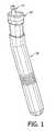
- FIG. 1depicts a three-dimensional view of a cleaning and storage system for a body cavity aspirator instrument in accordance with one embodiment.
- FIG. 2is an exploded view of the cleaning and storage system depicted in FIG. 1 .
- FIG. 3is longitudinal view of a disposable insert for a cleaning and storage system for a body cavity aspirator instrument in accordance with one embodiment.
- FIG. 4is a three-dimensional view of the disposable insert depicted in FIG. 3 .
- FIG. 5is a cross-sectional three-dimensional view of the disposable insert depicted in FIGS. 3 and 4 .
- FIGS. 6 and 7are perspective views of a disposable holster including a pinch that provides internal instrument supports.
- FIG. 8is a partial perspective transparent view of the holster of FIGS. 6 and 7 showing the instrument supports supporting an instrument.
- FIGS. 1 and 2there is illustrated a cleaning and storage system for a body cavity aspirator instrument, according to one embodiment.
- the systemincludes a hollow holder 30 that can be formed of a moldable plastic material.
- the systemfurther includes a removable and disposable insert 20 that fits within the hollow section of the hollow holder 30 .
- the holder 30 and disposable insert 20make up the cleaning and storage system for a body cavity aspirator instrument 10 , which is also depicted in FIGS. 1 and 2 .
- the holder 30has three regions or ends: a proximal region 35 ; a medial region 40 ; and a distal region 45 .
- the proximal region 35forms an opening 37 that receives the disposable insert 20 .
- the medial region 40forms a transition between the proximal and distal regions. While the holder 30 is substantially longitudinal, the medial region 40 may form a bend that results in the proximal region 35 being at an angle ⁇ relative to the distal region 45 . In other words, a longitudinal axis of the proximal region 35 is at an angle ⁇ relative to the longitudinal axis of the distal region 45 .
- the angle ⁇can be designed to be substantially complementary to a given type of aspirator instrument, such as the Yankauer tip mouthpiece instrument 10 .
- the angle ⁇is between about 0 degrees and about 12 degrees.
- the angle ⁇is between about 12 degrees and about 16 degrees.
- the angle ⁇is between about 13 degrees and about 15 degrees.
- the angle ⁇is about 14 degrees.
- the angle ⁇is greater than 16 degrees.
- the removable and disposable insert 20like the holder 30 , has three regions or ends: a proximal region 50 , a medial region 60 , and a distal region 70 .
- the insert 20forms a hollow tube that is closed at its distal region 70 .
- the proximal region 50 of the insert 20forms an opening 57 through which the aspirator instrument 10 can be inserted into the insert 20 .
- the medial region 60forms a transition between the proximal and distal regions.
- the medial region 60can form a bend that results in the proximal region 50 being at an angle ⁇ 1 relative to the distal region 70 .
- a longitudinal axis of the proximal region 50is at an angle ⁇ 1 relative to the longitudinal axis of the distal region 70 .
- the angle ⁇ 1can be designed to be substantially complementary to a given type of aspirator instrument, such as the Yankauer tip mouthpiece instrument 10 .
- the angle ⁇ 1is between about 0 degrees and about 12 degrees.
- the angle ⁇ 1is between about 12 degrees and about 16 degrees.
- the angle ⁇ 1is between about 13 degrees and about 15 degrees.
- the angle ⁇ 1is about 14 degrees.
- the angle ⁇ 1is greater than 16 degrees.
- the angle ⁇ 1can be substantially complementary to the angle ⁇ formed by the medial region 40 of the holder 30 .
- the proximal region 50 of the removable and disposable insert 20has a proximal end that forms a lip 55 .
- the lip 55folds down a distance toward the medial and distal regions or ends of the insert 20 .
- the lipcan have a circumference and shape that is complementary to the proximal region or end 35 of the holder 30 .
- the insert 20can be supported by the interface between the top edge 38 of the holder 30 and the bottom surface 58 of the lip 55 . Accordingly, the insert 20 can be easily removed from the holder 30 by pulling or pushing up on the top lip 55 of the insert 20 .
- the insert 20also optionally has one or more accordion pleats 65 defined along a portion of the distal region 70 of the insert 20 .
- the insert 20can have one, two, three, four, five, or more accordion pleats 65 in its distal region 70 .
- the accordion pleats 65allow the distal region of the insert 20 to bend as needed to accommodate the size and shape of the aspirator instrument 10 being used.
- a holster 72is attachable to a clip 80 or other fastener (collectively referred to hereinafter as a “clip,” for ease of reference) via a top lip 74 on the proximal region of the holster 72 .
- the top lip 74optionally slides over an outwardly protruding attachment piece 77 on the clip 80 .
- a separate holder 30is not required to house the holster 72 , which is preferably disposable.
- the holster 72may include one or more pleats 65 , a bend, or any other features that are optionally included on the insert 20 .
- the clip 80is attachable to a bedrail, ventilator, hospital stand, wall, or other suitable object. As illustrated in FIGS. 6 and 7 , the clip 80 optionally includes an arm 81 defining an opening that allows the arm 81 to slide over a bedrail.
- the clip 80may additionally or alternatively include one or more tie-straps for tying the clip 80 to an object, or may include an adhesive surface or pad for adhering the clip 80 to a wall or other object, or may include any other suitable attachment mechanism.
- the holster 72 or insert 20includes one or more upwardly projecting ledges 75 , or upright supports, or horizontal supports, located at an interior area of its distal region (the holster is optionally at least partially transparent, as shown in FIG. 8 ).
- the one or more ledges 75are used to support the tip 11 of an instrument 10 above a base region 76 of the holster 72 or insert 20 .
- the one or more ledges 75may be formed as part of the insert 20 or holster 72 itself, such as a “pinch” 82 of opposing walls of the closed end of the insert 20 or holster 72 , or they may be one or more separate pieces adhered to or otherwise affixed to the interior of the insert 20 or holster 72 .
- the distal regionincludes a pinch 82 , as shown in FIGS. 6-8 , the pinch 82 forms two upwardly projecting ledges 75 upon which the instrument 10 may rest.
Landscapes
- Health & Medical Sciences (AREA)
- Heart & Thoracic Surgery (AREA)
- Biomedical Technology (AREA)
- Vascular Medicine (AREA)
- Engineering & Computer Science (AREA)
- Anesthesiology (AREA)
- Surgery (AREA)
- Hematology (AREA)
- Life Sciences & Earth Sciences (AREA)
- Animal Behavior & Ethology (AREA)
- General Health & Medical Sciences (AREA)
- Public Health (AREA)
- Veterinary Medicine (AREA)
- External Artificial Organs (AREA)
Abstract
Description
Claims (8)
Priority Applications (2)
| Application Number | Priority Date | Filing Date | Title |
|---|---|---|---|
| US11/679,445US8833556B2 (en) | 2005-03-04 | 2007-02-27 | Suction tip holster insert |
| PCT/US2007/070789WO2007146826A2 (en) | 2006-06-14 | 2007-06-08 | Suction wand |
Applications Claiming Priority (2)
| Application Number | Priority Date | Filing Date | Title |
|---|---|---|---|
| US11/073,409US20060229567A1 (en) | 2005-03-04 | 2005-03-04 | Suction tip holster insert |
| US11/679,445US8833556B2 (en) | 2005-03-04 | 2007-02-27 | Suction tip holster insert |
Related Parent Applications (1)
| Application Number | Title | Priority Date | Filing Date |
|---|---|---|---|
| US11/073,409Continuation-In-PartUS20060229567A1 (en) | 2005-03-04 | 2005-03-04 | Suction tip holster insert |
Publications (2)
| Publication Number | Publication Date |
|---|---|
| US20070199846A1 US20070199846A1 (en) | 2007-08-30 |
| US8833556B2true US8833556B2 (en) | 2014-09-16 |
Family
ID=36953902
Family Applications (2)
| Application Number | Title | Priority Date | Filing Date |
|---|---|---|---|
| US11/073,409AbandonedUS20060229567A1 (en) | 2005-03-04 | 2005-03-04 | Suction tip holster insert |
| US11/679,445Expired - LifetimeUS8833556B2 (en) | 2005-03-04 | 2007-02-27 | Suction tip holster insert |
Family Applications Before (1)
| Application Number | Title | Priority Date | Filing Date |
|---|---|---|---|
| US11/073,409AbandonedUS20060229567A1 (en) | 2005-03-04 | 2005-03-04 | Suction tip holster insert |
Country Status (2)
| Country | Link |
|---|---|
| US (2) | US20060229567A1 (en) |
| WO (1) | WO2006096556A2 (en) |
Cited By (3)
| Publication number | Priority date | Publication date | Assignee | Title |
|---|---|---|---|---|
| USD773656S1 (en)* | 2015-01-30 | 2016-12-06 | Newgen Surgical, Inc. | Pencil electrode holder |
| US10398886B2 (en) | 2015-10-02 | 2019-09-03 | Myers Devices LLC | Aspiration apparatus and method of using the same |
| US20230405267A1 (en)* | 2017-10-25 | 2023-12-21 | Hollister Incorporated | Caps for Catheter Packages |
Families Citing this family (5)
| Publication number | Priority date | Publication date | Assignee | Title |
|---|---|---|---|---|
| US8012141B2 (en)* | 2007-03-29 | 2011-09-06 | Wright Clifford A | Suction wand |
| US7913959B2 (en)* | 2008-02-08 | 2011-03-29 | Patient Shield Concepts, Llc | Medical/dental suction nozzle holster having a universally adjustable strap |
| US8245857B2 (en)* | 2008-06-16 | 2012-08-21 | Trademark Medical, Llc | Medical device holder assembly |
| US9010530B2 (en)* | 2012-11-27 | 2015-04-21 | Synaptic Wireless, Llc | Self-orienting desiccant holder for use with in a suction device |
| CN104968380B (en) | 2013-01-29 | 2018-08-21 | 赛诺菲-安万特德国有限公司 | Assemblies for detecting plunger position |
Citations (35)
| Publication number | Priority date | Publication date | Assignee | Title |
|---|---|---|---|---|
| US2522381A (en) | 1948-01-24 | 1950-09-12 | Kramer William | Temperature retaining cover for baby bottles and other receptacles |
| US2994457A (en)* | 1959-08-20 | 1961-08-01 | Levi L Fornas | Stacking and nesting box |
| US3275180A (en)* | 1965-01-04 | 1966-09-27 | Lermer Packaging Corp | Mailing container construction |
| US3388705A (en) | 1965-04-08 | 1968-06-18 | Foregger Company Inc | Universal endotracheal tube coupling or adaptor |
| US3819081A (en)* | 1971-03-12 | 1974-06-25 | Harre & Co A | Mailer for biological samples |
| US3826358A (en)* | 1972-05-10 | 1974-07-30 | Miles Lab | Package for tablets |
| US4050466A (en)* | 1975-10-08 | 1977-09-27 | Koerbacher Kathleen C | Endotracheal tube |
| US4061226A (en)* | 1976-06-24 | 1977-12-06 | Intec Industries Inc. | Thermometer case and holder |
| US4094641A (en)* | 1977-02-25 | 1978-06-13 | Waters Associates, Inc. | Low loss sample bottle assembly |
| US4439884A (en) | 1981-04-07 | 1984-04-03 | Gastone Giorni | Container with bristles for cleaning instruments |
| US4748007A (en) | 1985-11-27 | 1988-05-31 | Vetrodyne, Inc. | Endoscope disinfecting and storing device |
| US4761379A (en)* | 1984-08-09 | 1988-08-02 | Becton, Dickinson And Company | Biological specimen collection device |
| US4813538A (en) | 1987-03-19 | 1989-03-21 | Blackman Seymour N | Re-usable sterile parenteral fluid medication administration kit |
| US4921488A (en) | 1988-01-15 | 1990-05-01 | Maitz Carlos A | Aspirator device for body fluids |
| US5002534A (en) | 1988-06-22 | 1991-03-26 | Rosenblatt/Ima Invention Enterprises | Aspirator without partition wall for collection of bodily fluids including improved safety and efficiency elements |
| US5038766A (en) | 1989-11-08 | 1991-08-13 | Parker Jeffrey D | Blind orolaryngeal and oroesophageal guiding and aiming device |
| US5062835A (en) | 1988-01-15 | 1991-11-05 | Maitz Carlos A | Aspirator device for body fluids |
| US5183467A (en) | 1990-05-01 | 1993-02-02 | Mouney Daniel F | Nasal aspirator |
| US5316146A (en)* | 1991-03-06 | 1994-05-31 | Ulster Scientific, Inc. | Vial transporter |
| US5333607A (en) | 1992-10-19 | 1994-08-02 | Sherwood Medical Company | Ventilator manifold with accessory access port |
| US5375711A (en) | 1993-03-08 | 1994-12-27 | Bree; Lorraine | Bent toothbrush holder |
| US5454131A (en) | 1994-05-02 | 1995-10-03 | Mackenzie; Madeline E. | Apparatuses for cleaning and sanitizing combs through mechanical bristles and disinfectant fluids |
| US5471706A (en) | 1992-12-14 | 1995-12-05 | James M. Leu | Means for cleaning of health care instruments |
| US5590782A (en)* | 1995-04-17 | 1997-01-07 | Habley Medical Technology Corporation | Vial holder assembly |
| US5634569A (en)* | 1996-01-18 | 1997-06-03 | Dart Industries Inc. | Food container with dispensing means |
| US5752286A (en) | 1995-12-21 | 1998-05-19 | Wright; Clifford A. | Cleaning and storage system for a body cavity aspirator instrument |
| USD405531S (en) | 1998-03-26 | 1999-02-09 | Bonds Crystal C | Collapsible baby bottle |
| US5915583A (en) | 1997-05-21 | 1999-06-29 | Abbott Laboraties | Container |
| US5945075A (en)* | 1995-03-01 | 1999-08-31 | Merck Biomaterial France | Protective box for sterilizing and preserving organic matter or material and assembly applying same |
| US6183133B1 (en) | 1996-06-26 | 2001-02-06 | Roegner Deanna | Expanable multipocket carrying case |
| US6299116B1 (en)* | 1997-03-27 | 2001-10-09 | Micheline Levesque | Circular flowerpot support |
| US20020172257A1 (en)* | 2001-05-17 | 2002-11-21 | James Walls | Probe cover with lubrication well |
| US6585210B1 (en)* | 2002-06-19 | 2003-07-01 | Super Link Electronics Co., Ltd. | Secure pen holding mechanism |
| US20050194507A1 (en)* | 2004-03-02 | 2005-09-08 | White Lynn R. | Medical suction nozzle holster |
| US7712622B2 (en)* | 2004-07-16 | 2010-05-11 | Ruccolo Joseph D | Child's drinking cup |
Family Cites Families (2)
| Publication number | Priority date | Publication date | Assignee | Title |
|---|---|---|---|---|
| US6092681A (en)* | 1997-07-17 | 2000-07-25 | Johnson & Johnson Consumer Products, Inc. | Holder for use in disposable feeding systems |
| US20060078656A1 (en)* | 2004-10-07 | 2006-04-13 | Pbm Products, Inc. | Ready-to-use bottle liners containing premeasured amount of infant formula and methods of making the same |
- 2005
- 2005-03-04USUS11/073,409patent/US20060229567A1/ennot_activeAbandoned
- 2006
- 2006-03-03WOPCT/US2006/007712patent/WO2006096556A2/enactiveSearch and Examination
- 2007
- 2007-02-27USUS11/679,445patent/US8833556B2/ennot_activeExpired - Lifetime
Patent Citations (35)
| Publication number | Priority date | Publication date | Assignee | Title |
|---|---|---|---|---|
| US2522381A (en) | 1948-01-24 | 1950-09-12 | Kramer William | Temperature retaining cover for baby bottles and other receptacles |
| US2994457A (en)* | 1959-08-20 | 1961-08-01 | Levi L Fornas | Stacking and nesting box |
| US3275180A (en)* | 1965-01-04 | 1966-09-27 | Lermer Packaging Corp | Mailing container construction |
| US3388705A (en) | 1965-04-08 | 1968-06-18 | Foregger Company Inc | Universal endotracheal tube coupling or adaptor |
| US3819081A (en)* | 1971-03-12 | 1974-06-25 | Harre & Co A | Mailer for biological samples |
| US3826358A (en)* | 1972-05-10 | 1974-07-30 | Miles Lab | Package for tablets |
| US4050466A (en)* | 1975-10-08 | 1977-09-27 | Koerbacher Kathleen C | Endotracheal tube |
| US4061226A (en)* | 1976-06-24 | 1977-12-06 | Intec Industries Inc. | Thermometer case and holder |
| US4094641A (en)* | 1977-02-25 | 1978-06-13 | Waters Associates, Inc. | Low loss sample bottle assembly |
| US4439884A (en) | 1981-04-07 | 1984-04-03 | Gastone Giorni | Container with bristles for cleaning instruments |
| US4761379A (en)* | 1984-08-09 | 1988-08-02 | Becton, Dickinson And Company | Biological specimen collection device |
| US4748007A (en) | 1985-11-27 | 1988-05-31 | Vetrodyne, Inc. | Endoscope disinfecting and storing device |
| US4813538A (en) | 1987-03-19 | 1989-03-21 | Blackman Seymour N | Re-usable sterile parenteral fluid medication administration kit |
| US5062835A (en) | 1988-01-15 | 1991-11-05 | Maitz Carlos A | Aspirator device for body fluids |
| US4921488A (en) | 1988-01-15 | 1990-05-01 | Maitz Carlos A | Aspirator device for body fluids |
| US5002534A (en) | 1988-06-22 | 1991-03-26 | Rosenblatt/Ima Invention Enterprises | Aspirator without partition wall for collection of bodily fluids including improved safety and efficiency elements |
| US5038766A (en) | 1989-11-08 | 1991-08-13 | Parker Jeffrey D | Blind orolaryngeal and oroesophageal guiding and aiming device |
| US5183467A (en) | 1990-05-01 | 1993-02-02 | Mouney Daniel F | Nasal aspirator |
| US5316146A (en)* | 1991-03-06 | 1994-05-31 | Ulster Scientific, Inc. | Vial transporter |
| US5333607A (en) | 1992-10-19 | 1994-08-02 | Sherwood Medical Company | Ventilator manifold with accessory access port |
| US5471706A (en) | 1992-12-14 | 1995-12-05 | James M. Leu | Means for cleaning of health care instruments |
| US5375711A (en) | 1993-03-08 | 1994-12-27 | Bree; Lorraine | Bent toothbrush holder |
| US5454131A (en) | 1994-05-02 | 1995-10-03 | Mackenzie; Madeline E. | Apparatuses for cleaning and sanitizing combs through mechanical bristles and disinfectant fluids |
| US5945075A (en)* | 1995-03-01 | 1999-08-31 | Merck Biomaterial France | Protective box for sterilizing and preserving organic matter or material and assembly applying same |
| US5590782A (en)* | 1995-04-17 | 1997-01-07 | Habley Medical Technology Corporation | Vial holder assembly |
| US5752286A (en) | 1995-12-21 | 1998-05-19 | Wright; Clifford A. | Cleaning and storage system for a body cavity aspirator instrument |
| US5634569A (en)* | 1996-01-18 | 1997-06-03 | Dart Industries Inc. | Food container with dispensing means |
| US6183133B1 (en) | 1996-06-26 | 2001-02-06 | Roegner Deanna | Expanable multipocket carrying case |
| US6299116B1 (en)* | 1997-03-27 | 2001-10-09 | Micheline Levesque | Circular flowerpot support |
| US5915583A (en) | 1997-05-21 | 1999-06-29 | Abbott Laboraties | Container |
| USD405531S (en) | 1998-03-26 | 1999-02-09 | Bonds Crystal C | Collapsible baby bottle |
| US20020172257A1 (en)* | 2001-05-17 | 2002-11-21 | James Walls | Probe cover with lubrication well |
| US6585210B1 (en)* | 2002-06-19 | 2003-07-01 | Super Link Electronics Co., Ltd. | Secure pen holding mechanism |
| US20050194507A1 (en)* | 2004-03-02 | 2005-09-08 | White Lynn R. | Medical suction nozzle holster |
| US7712622B2 (en)* | 2004-07-16 | 2010-05-11 | Ruccolo Joseph D | Child's drinking cup |
Cited By (4)
| Publication number | Priority date | Publication date | Assignee | Title |
|---|---|---|---|---|
| USD773656S1 (en)* | 2015-01-30 | 2016-12-06 | Newgen Surgical, Inc. | Pencil electrode holder |
| US10398886B2 (en) | 2015-10-02 | 2019-09-03 | Myers Devices LLC | Aspiration apparatus and method of using the same |
| US20230405267A1 (en)* | 2017-10-25 | 2023-12-21 | Hollister Incorporated | Caps for Catheter Packages |
| US12171954B2 (en)* | 2017-10-25 | 2024-12-24 | Hollister Incorporated | Caps for catheter packages |
Also Published As
| Publication number | Publication date |
|---|---|
| WO2006096556A3 (en) | 2007-06-14 |
| WO2006096556A2 (en) | 2006-09-14 |
| US20060229567A1 (en) | 2006-10-12 |
| US20070199846A1 (en) | 2007-08-30 |
Similar Documents
| Publication | Publication Date | Title |
|---|---|---|
| US8833556B2 (en) | Suction tip holster insert | |
| JP5951013B2 (en) | Insertion aid | |
| US7802574B2 (en) | Medical component system | |
| EP2424585B1 (en) | Nasal aspirator | |
| US20080251102A1 (en) | Cleaning device for endoscopic devices | |
| US20060278781A1 (en) | Medical device mount | |
| US20050230280A1 (en) | Sanitary support device for a medical instrument | |
| US20100016817A1 (en) | Bedside suction cup | |
| KR102363622B1 (en) | Medical suction unit | |
| KR101729027B1 (en) | Detachable Catheter Structure | |
| WO2023060338A1 (en) | Apparatus for irrigation, suctioning and obtaining samples of the oral cavity | |
| CN210612590U (en) | A sputum suction tube and a sputum suction device provided with the sputum suction tube | |
| CN221490204U (en) | An integrated tracheotomy cannula cleaning and disinfection box | |
| KR101135203B1 (en) | Fixing clip for catheter | |
| US20250000627A1 (en) | Apparatus for irrigation, suctioning and obtaining samples of the oral cavity | |
| KR102075698B1 (en) | Catheter Guide Structure Being Capable of Adjunting Inserting Direction and Angel of Catheter | |
| CN220158653U (en) | A disposable sputum suction care tray | |
| JP4033533B2 (en) | Medical spray equipment | |
| US20240009336A1 (en) | Apparatus for sterilizing medical instruments | |
| CN211884346U (en) | A bronchoscopy protective cover | |
| CN215194064U (en) | Disposable sterilizing container for suction device | |
| CN221535042U (en) | Bronchoscope sputum aspirator | |
| CN213130030U (en) | Oral nursing vascular forceps | |
| CN211751334U (en) | Portable phlegm suction device | |
| JP4809369B2 (en) | Winged needle holder |
Legal Events
| Date | Code | Title | Description |
|---|---|---|---|
| AS | Assignment | Owner name:MEDICAL DEVICE GROUP, INC., CALIFORNIA Free format text:ASSIGNMENT OF ASSIGNORS INTEREST;ASSIGNOR:WRIGHT, CLIFFORD A.;REEL/FRAME:019302/0595 Effective date:20070516 | |
| AS | Assignment | Owner name:IAPYX MEDICAL, INC., NEVADA Free format text:ASSIGNMENT OF ASSIGNORS INTEREST;ASSIGNOR:WRIGHT, CLIFFORD A.;REEL/FRAME:037721/0591 Effective date:20130205 Owner name:WRIGHT, CLIFFORD A., CALIFORNIA Free format text:ASSET PURCHASE AGREEMENT;ASSIGNOR:DEVELOPMENT SPECIALISTS, INC., SOLELY IN ITS CAPACITY AS THE ASSIGNEE FOR THE BENEFIT OF CREDITORS OF MEDICAL DEVICE GROUP, INC., D/B/A IAPYX, INC.;REEL/FRAME:037809/0125 Effective date:20120209 | |
| FEPP | Fee payment procedure | Free format text:MAINTENANCE FEE REMINDER MAILED (ORIGINAL EVENT CODE: REM.) | |
| LAPS | Lapse for failure to pay maintenance fees | Free format text:PATENT EXPIRED FOR FAILURE TO PAY MAINTENANCE FEES (ORIGINAL EVENT CODE: EXP.); ENTITY STATUS OF PATENT OWNER: SMALL ENTITY | |
| STCH | Information on status: patent discontinuation | Free format text:PATENT EXPIRED DUE TO NONPAYMENT OF MAINTENANCE FEES UNDER 37 CFR 1.362 | |
| FP | Lapsed due to failure to pay maintenance fee | Effective date:20180916 | |
| FEPP | Fee payment procedure | Free format text:SURCHARGE, PETITION TO ACCEPT PYMT AFTER EXP, UNINTENTIONAL. (ORIGINAL EVENT CODE: M2558); ENTITY STATUS OF PATENT OWNER: SMALL ENTITY Free format text:PETITION RELATED TO MAINTENANCE FEES GRANTED (ORIGINAL EVENT CODE: PMFG); ENTITY STATUS OF PATENT OWNER: SMALL ENTITY Free format text:PETITION RELATED TO MAINTENANCE FEES FILED (ORIGINAL EVENT CODE: PMFP); ENTITY STATUS OF PATENT OWNER: SMALL ENTITY | |
| MAFP | Maintenance fee payment | Free format text:PAYMENT OF MAINTENANCE FEE, 4TH YR, SMALL ENTITY (ORIGINAL EVENT CODE: M2551); ENTITY STATUS OF PATENT OWNER: SMALL ENTITY Year of fee payment:4 | |
| STCF | Information on status: patent grant | Free format text:PATENTED CASE | |
| MAFP | Maintenance fee payment | Free format text:PAYMENT OF MAINTENANCE FEE, 8TH YR, SMALL ENTITY (ORIGINAL EVENT CODE: M2552); ENTITY STATUS OF PATENT OWNER: SMALL ENTITY Year of fee payment:8 |