US8833390B2 - Valve meter assembly and method - Google Patents
Valve meter assembly and methodDownload PDFInfo
- Publication number
- US8833390B2 US8833390B2US13/149,720US201113149720AUS8833390B2US 8833390 B2US8833390 B2US 8833390B2US 201113149720 AUS201113149720 AUS 201113149720AUS 8833390 B2US8833390 B2US 8833390B2
- Authority
- US
- United States
- Prior art keywords
- valve
- water
- meter
- assembly
- state
- Prior art date
- Legal status (The legal status is an assumption and is not a legal conclusion. Google has not performed a legal analysis and makes no representation as to the accuracy of the status listed.)
- Active, expires
Links
- 238000000034methodMethods0.000titleclaimsabstractdescription5
- XLYOFNOQVPJJNP-UHFFFAOYSA-NwaterSubstancesOXLYOFNOQVPJJNP-UHFFFAOYSA-N0.000claimsabstractdescription237
- 238000004891communicationMethods0.000claimsabstractdescription67
- 238000012544monitoring processMethods0.000claimsdescription23
- 239000000463materialSubstances0.000claimsdescription8
- 230000009429distressEffects0.000claimsdescription6
- CWYNVVGOOAEACU-UHFFFAOYSA-NFe2+Chemical compound[Fe+2]CWYNVVGOOAEACU-UHFFFAOYSA-N0.000claimsdescription5
- 108091006146ChannelsProteins0.000description69
- 230000003993interactionEffects0.000description10
- 230000037361pathwayEffects0.000description10
- 229920003023plasticPolymers0.000description9
- 239000004033plasticSubstances0.000description9
- 238000010586diagramMethods0.000description7
- 230000008859changeEffects0.000description6
- 230000007958sleepEffects0.000description6
- 238000013023gasketingMethods0.000description5
- 238000003466weldingMethods0.000description5
- 230000007704transitionEffects0.000description4
- 238000006073displacement reactionMethods0.000description3
- 230000014759maintenance of locationEffects0.000description3
- 238000007789sealingMethods0.000description3
- 230000009471actionEffects0.000description2
- 238000009412basement excavationMethods0.000description2
- 239000012530fluidSubstances0.000description2
- 230000006870functionEffects0.000description2
- 229920001903high density polyethylenePolymers0.000description2
- 239000012535impuritySubstances0.000description2
- 229910052744lithiumInorganic materials0.000description2
- 238000005259measurementMethods0.000description2
- 238000012986modificationMethods0.000description2
- 230000004048modificationEffects0.000description2
- 238000011144upstream manufacturingMethods0.000description2
- 229910001369BrassInorganic materials0.000description1
- 229910000906BronzeInorganic materials0.000description1
- 229910000831SteelInorganic materials0.000description1
- XAGFODPZIPBFFR-UHFFFAOYSA-NaluminiumChemical compound[Al]XAGFODPZIPBFFR-UHFFFAOYSA-N0.000description1
- 229910052782aluminiumInorganic materials0.000description1
- 230000000712assemblyEffects0.000description1
- 238000000429assemblyMethods0.000description1
- 239000010951brassSubstances0.000description1
- 239000010974bronzeSubstances0.000description1
- 238000005266castingMethods0.000description1
- 230000000295complement effectEffects0.000description1
- 238000010276constructionMethods0.000description1
- KUNSUQLRTQLHQQ-UHFFFAOYSA-Ncopper tinChemical compound[Cu].[Sn]KUNSUQLRTQLHQQ-UHFFFAOYSA-N0.000description1
- 230000008878couplingEffects0.000description1
- 238000010168coupling processMethods0.000description1
- 238000005859coupling reactionMethods0.000description1
- 238000005516engineering processMethods0.000description1
- 239000011521glassSubstances0.000description1
- 239000003292glueSubstances0.000description1
- 238000005304joiningMethods0.000description1
- 230000007246mechanismEffects0.000description1
- 239000002245particleSubstances0.000description1
- 230000000704physical effectEffects0.000description1
- 238000004023plastic weldingMethods0.000description1
- 230000001737promoting effectEffects0.000description1
- 238000004904shorteningMethods0.000description1
- 239000010959steelSubstances0.000description1
Images

Classifications
- G—PHYSICS
- G01—MEASURING; TESTING
- G01F—MEASURING VOLUME, VOLUME FLOW, MASS FLOW OR LIQUID LEVEL; METERING BY VOLUME
- G01F15/00—Details of, or accessories for, apparatus of groups G01F1/00 - G01F13/00 insofar as such details or appliances are not adapted to particular types of such apparatus
- G01F15/14—Casings, e.g. of special material
- E—FIXED CONSTRUCTIONS
- E03—WATER SUPPLY; SEWERAGE
- E03B—INSTALLATIONS OR METHODS FOR OBTAINING, COLLECTING, OR DISTRIBUTING WATER
- E03B7/00—Water main or service pipe systems
- E03B7/07—Arrangement of devices, e.g. filters, flow controls, measuring devices, siphons or valves, in the pipe systems
- E03B7/072—Arrangement of flowmeters
- G—PHYSICS
- G01—MEASURING; TESTING
- G01F—MEASURING VOLUME, VOLUME FLOW, MASS FLOW OR LIQUID LEVEL; METERING BY VOLUME
- G01F15/00—Details of, or accessories for, apparatus of groups G01F1/00 - G01F13/00 insofar as such details or appliances are not adapted to particular types of such apparatus
- G01F15/001—Means for regulating or setting the meter for a predetermined quantity
- G01F15/003—Means for regulating or setting the meter for a predetermined quantity using electromagnetic, electric or electronic means
- G—PHYSICS
- G01—MEASURING; TESTING
- G01F—MEASURING VOLUME, VOLUME FLOW, MASS FLOW OR LIQUID LEVEL; METERING BY VOLUME
- G01F15/00—Details of, or accessories for, apparatus of groups G01F1/00 - G01F13/00 insofar as such details or appliances are not adapted to particular types of such apparatus
- G01F15/005—Valves
- G—PHYSICS
- G01—MEASURING; TESTING
- G01F—MEASURING VOLUME, VOLUME FLOW, MASS FLOW OR LIQUID LEVEL; METERING BY VOLUME
- G01F15/00—Details of, or accessories for, apparatus of groups G01F1/00 - G01F13/00 insofar as such details or appliances are not adapted to particular types of such apparatus
- G01F15/06—Indicating or recording devices
- G01F15/061—Indicating or recording devices for remote indication
- G—PHYSICS
- G01—MEASURING; TESTING
- G01F—MEASURING VOLUME, VOLUME FLOW, MASS FLOW OR LIQUID LEVEL; METERING BY VOLUME
- G01F15/00—Details of, or accessories for, apparatus of groups G01F1/00 - G01F13/00 insofar as such details or appliances are not adapted to particular types of such apparatus
- G01F15/06—Indicating or recording devices
- G01F15/065—Indicating or recording devices with transmission devices, e.g. mechanical
- G01F15/066—Indicating or recording devices with transmission devices, e.g. mechanical involving magnetic transmission devices
- G—PHYSICS
- G01—MEASURING; TESTING
- G01F—MEASURING VOLUME, VOLUME FLOW, MASS FLOW OR LIQUID LEVEL; METERING BY VOLUME
- G01F3/00—Measuring the volume flow of fluids or fluent solid material wherein the fluid passes through the meter in successive and more or less isolated quantities, the meter being driven by the flow
- G01F3/02—Measuring the volume flow of fluids or fluent solid material wherein the fluid passes through the meter in successive and more or less isolated quantities, the meter being driven by the flow with measuring chambers which expand or contract during measurement
- G01F3/04—Measuring the volume flow of fluids or fluent solid material wherein the fluid passes through the meter in successive and more or less isolated quantities, the meter being driven by the flow with measuring chambers which expand or contract during measurement having rigid movable walls
- G01F3/06—Measuring the volume flow of fluids or fluent solid material wherein the fluid passes through the meter in successive and more or less isolated quantities, the meter being driven by the flow with measuring chambers which expand or contract during measurement having rigid movable walls comprising members rotating in a fluid-tight or substantially fluid-tight manner in a housing
- G01F3/12—Meters with nutating members, e.g. discs
- G—PHYSICS
- G05—CONTROLLING; REGULATING
- G05D—SYSTEMS FOR CONTROLLING OR REGULATING NON-ELECTRIC VARIABLES
- G05D7/00—Control of flow
- G05D7/06—Control of flow characterised by the use of electric means
- G05D7/0617—Control of flow characterised by the use of electric means specially adapted for fluid materials
- G05D7/0629—Control of flow characterised by the use of electric means specially adapted for fluid materials characterised by the type of regulator means
- Y—GENERAL TAGGING OF NEW TECHNOLOGICAL DEVELOPMENTS; GENERAL TAGGING OF CROSS-SECTIONAL TECHNOLOGIES SPANNING OVER SEVERAL SECTIONS OF THE IPC; TECHNICAL SUBJECTS COVERED BY FORMER USPC CROSS-REFERENCE ART COLLECTIONS [XRACs] AND DIGESTS
- Y10—TECHNICAL SUBJECTS COVERED BY FORMER USPC
- Y10T—TECHNICAL SUBJECTS COVERED BY FORMER US CLASSIFICATION
- Y10T137/00—Fluid handling
- Y10T137/0318—Processes
- Y—GENERAL TAGGING OF NEW TECHNOLOGICAL DEVELOPMENTS; GENERAL TAGGING OF CROSS-SECTIONAL TECHNOLOGIES SPANNING OVER SEVERAL SECTIONS OF THE IPC; TECHNICAL SUBJECTS COVERED BY FORMER USPC CROSS-REFERENCE ART COLLECTIONS [XRACs] AND DIGESTS
- Y10—TECHNICAL SUBJECTS COVERED BY FORMER USPC
- Y10T—TECHNICAL SUBJECTS COVERED BY FORMER US CLASSIFICATION
- Y10T137/00—Fluid handling
- Y10T137/7722—Line condition change responsive valves
- Y10T137/7758—Pilot or servo controlled
- Y10T137/7759—Responsive to change in rate of fluid flow
- Y—GENERAL TAGGING OF NEW TECHNOLOGICAL DEVELOPMENTS; GENERAL TAGGING OF CROSS-SECTIONAL TECHNOLOGIES SPANNING OVER SEVERAL SECTIONS OF THE IPC; TECHNICAL SUBJECTS COVERED BY FORMER USPC CROSS-REFERENCE ART COLLECTIONS [XRACs] AND DIGESTS
- Y10—TECHNICAL SUBJECTS COVERED BY FORMER USPC
- Y10T—TECHNICAL SUBJECTS COVERED BY FORMER US CLASSIFICATION
- Y10T137/00—Fluid handling
- Y10T137/8158—With indicator, register, recorder, alarm or inspection means
- Y10T137/8175—Plural
- Y—GENERAL TAGGING OF NEW TECHNOLOGICAL DEVELOPMENTS; GENERAL TAGGING OF CROSS-SECTIONAL TECHNOLOGIES SPANNING OVER SEVERAL SECTIONS OF THE IPC; TECHNICAL SUBJECTS COVERED BY FORMER USPC CROSS-REFERENCE ART COLLECTIONS [XRACs] AND DIGESTS
- Y10—TECHNICAL SUBJECTS COVERED BY FORMER USPC
- Y10T—TECHNICAL SUBJECTS COVERED BY FORMER US CLASSIFICATION
- Y10T137/00—Fluid handling
- Y10T137/8593—Systems
Definitions
- the present disclosurerelates to water control and metering, specifically water flow monitoring and control.
- Wateris typically supplied by a water provider which is usually a municipality. Water providers deliver water to businesses and individuals via piping systems.
- a piping systemcould be an upstream piping system, including a system to carry water from a water provider to a meter, or a downstream piping system, including a system to carry water from a meter to a user terminal. Because water providers typically sell water by unit volume, there exists a need to measure water flow to a user terminal to generate a water bill.
- user terminalmay include an individual residence, a place of business or any other point of termination of the water flow.
- a water meterwill be placed in the water supply line between the water source and the user terminal to measure all water flowing to that user terminal. Meters are read and checked against prior readings to determine the total flow of water to the user terminal.
- a water providerWhen a water user has not provided payment for water already used, it is typical in the industry for a water provider to discontinue supplying water to the user terminal associated with the water user. Typically, a water provider will install a manual water supply valve in the supply line in anticipation of the need to discontinue water supply. Although the valve may be operated rarely, a manual valve is standard equipment for water providers.
- water metersare read manually by water meter readers who are employees or contractors of the water providers. Additionally, it is also typical that water supply valves are manually operated by employees or contractors of the water providers. These manual operations associated with providing water represent a significant cost of a typical water provider. With the advent of wireless technology, water providers have sought methods and systems for remote reading of water meters and/or remote control of water supply valves.
- Some systems designed to fit into the standard water meter lay-length of a water meterprovide inordinate head loss through the system and provide only remote control of the valve and no ability to read the meter remotely.
- wireless water supply valvestypically have relatively short operative lives because their operation requires large amounts of energy.
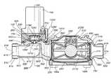
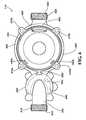
- FIG. 1is a perspective view of a valve meter device in accordance with one embodiment of the disclosure.
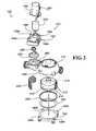
- FIG. 2is an exploded view of the valve meter device of FIG. 1 .
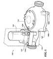
- FIG. 3is a side view of the device housing of the valve meter device of FIG. 1 .
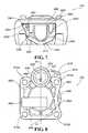
- FIG. 4is a bottom view of the device housing of FIG. 3 .
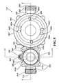
- FIG. 5is a top view of the device housing of FIG. 3 .
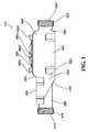
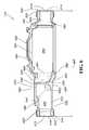
- FIG. 6is a sectional view of the device housing of FIG. 5 taken in a plane indicated by line 6 in FIG. 5 .
- FIG. 7is a sectional view of the valve portion of the device housing of FIG. 5 taken in a plane indicated by line 7 in FIG. 5 .
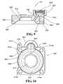
- FIG. 8is a top view of the valve cover of the valve meter device of FIG. 1 .
- FIG. 9is sectional view of the valve cover of FIG. 8 taken in a plane indicated by line 9 in FIG. 8 .
- FIG. 10is a bottom view of the valve cover of FIG. 8 .
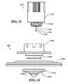
- FIG. 11is a side view of the solenoid of the valve meter device of FIG. 1 .
- FIG. 12is an exploded view of the diaphragm assembly of the valve meter device of FIG. 1 .
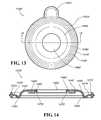
- FIG. 13is a top view of the diaphragm of the diaphragm assembly of FIG. 12 .
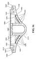
- FIG. 14is a sectional view of the diaphragm of FIG. 13 taken in a plane indicated by line 14 in FIG. 13 .
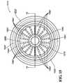
- FIG. 15is a top view of the valve cone of the diaphragm assembly of FIG. 12 .
- FIG. 16is a sectional view of the valve cone of FIG. 15 taken in a plane indicated by line 16 in FIG. 15 .
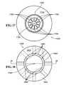
- FIG. 17is a bottom view of the backing plate of the diaphragm assembly of FIG. 12 .
- FIG. 18is a top view of the backing plate of FIG. 17 .
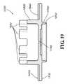
- FIG. 19is a sectional view of the backing plate of FIG. 17 taken in a plane indicated by line 19 in FIG. 18 .
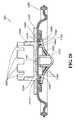
- FIG. 20is a sectional view of the diaphragm assembly of the valve meter device of FIG. 1 taken in a plane proceeding over the diameter of the assembly.
- FIG. 21is a sectional view of the water meter of the valve meter device of FIG. 1 taken in a plane proceeding through the center axis of the flow path of water through the valve meter device FIG. 1 .
- FIG. 22is a side view of a register assembly included in accord with one embodiment of the valve meter device of FIG. 1 .
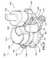
- FIG. 23is a perspective view of a valve meter assembly including the valve meter device of FIG. 1 , the register assembly of FIG. 22 , and a wireless communication unit included in accord with one embodiment of the disclosure.
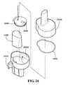
- FIG. 24is an exploded view of the wireless communication unit of the valve meter device of FIG. 23 .
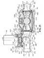
- FIG. 25is a sectional view of the valve meter device of FIG. 1 taken in a plane proceeding through the center axis of the flow path of water through the valve meter device.
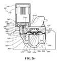
- FIG. 26is a sectional view of the valve meter device of FIG. 1 taken in a plane indicated by line 26 in FIG. 25 wherein the valve meter device is in the “open” state with the water supply valve and solenoid “open.”
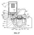
- FIG. 27is the sectional view FIG. 26 wherein the valve meter device is in a dynamic state with the solenoid in the “closed” position and the water supply valve in the “open” state.
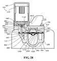
- FIG. 28is the sectional view FIG. 26 wherein the valve meter device is in the “closed” state with the water supply valve and solenoid “closed.”
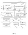
- FIG. 29is a circuit diagram of the valve meter assembly of FIG. 23 .
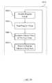
- FIG. 30is a flow diagram illustrating functioning of a register circuit of the valve meter assembly of FIG. 23 .
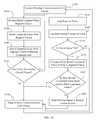
- FIG. 31is a flow diagram illustrating functioning of a wireless communication unit circuit, including a valve monitoring circuit, of the valve meter assembly of FIG. 23 .
- the valve meter deviceincludes a water supply valve and a water meter dimensioned together to fit within a standard water meter lay-length with reduced head loss.
- the valve meter deviceincludes a water meter and at least part of a water supply valve together in one housing.
- the valve meter deviceis capable of communicating with a remotely located communicator.
- the remotely located communicatormay receive signals from the valve meter device, send signals to the valve meter device, or both send signals to and receive signals from the valve meter device.
- FIG. 1is a perspective view of one embodiment of a valve meter device 100 .
- the valve meter device 100includes a device housing 110 .
- the device housing 110forms the main body through which water will flow.
- a valve cover 120is attached to the device housing 110 using valve cover screws 130 a,b ( 130 c,d not shown).
- a solenoid tamper cover 140is attached to the top of the valve cover 120 .
- a bottom plate 150is attached to the device housing 110 with bottom plate screws 160 a,b ( 160 c,d not shown).
- references to “top”, “bottom”, “down”, “up”, “downward”, or “upward”refer to the valve meter device 100 as oriented in FIG. 1 .
- Various features of the valve meter device 100may be altered, reoriented, reconfigured, replaced, rotated, or moved in alternative embodiments. No one configuration is intended to be limiting on this disclosure.
- the valve meter device 100includes a water supply valve 170 and a water meter 210 (shown in FIG. 2 ).
- the water supply valve 170is partially integrated with the device housing 110 and includes the valve cover 120 screwed onto the device housing 110 to enclose some components of the water supply valve 170 inside a cavity defined between the valve cover 120 and the device housing 110 .
- the current embodimentincludes a partially integrated construction with a separately attached cover
- alternative embodimentsare included in this disclosure and may include a plastic welded assembly, separate valve and device housing subassemblies connected together via plastic welding, or separate valve and device housing subassemblies connected together mechanically, among others.
- FIG. 2is an exploded view of the valve meter device 100 .
- the device housing 110includes a meter portion 264 and a valve portion 265 .
- the device housing 110 and bottom plate 150are configured to enclose a water meter 210 and a strainer retainer 220 in the meter portion 264 .
- the bottom plate 150is attached to the device housing 110 with bottom plate screws 160 a - d .
- a meter gasket 230is inserted between the bottom plate 150 and the device housing 110 .
- a bottom plastic liner 240is inserted between the bottom plate 150 and the device housing 110 .
- the meter 210 in the current embodimentis a nutating disc displacement flow meter. Other meter types may be used with the valve meter device 100 .
- the meter 210has a metering inlet 212 and a metering outlet 213 located proximate to each other. The metering outlet 213 is surrounded by a metering outlet rubber gasket 215 .
- the valve cover 120 and the valve portion 265 of the device housing 110enclose a spring 250 and a diaphragm assembly 260 .
- the solenoid tamper cover 140encloses a solenoid 270 and a valve orifice cylinder 280 onto the valve cover 120 .
- the valve orifice cylinder 280is a steel cylinder with a cylindrical bore extending its entire top to bottom length.
- the solenoid 270is attached to the valve cover 120 .
- the valve orifice cylinder 280sits in a media channel 520 (seen in FIG. 5 ) and interacts with the solenoid 270 to change water flow through the media channel 520 when the solenoid 270 is placed in an “open” or a “closed” position.
- valve orifice cylinder 280has a cylindrical shape in the current embodiment, but the valve orifice cylinder 280 may be various shapes.
- a solenoid tamper cover screw 290provides the attachment of the solenoid tamper cover 140 to the valve cover 120 .
- the spring 250may not be required for valve operation.
- Other parts of the water supply valve 170including the solenoid tamper cover 140 , may not be necessary in alternative embodiments of the valve meter device 100 .
- the valve cover 120 and the valve portion 265 of the device housing 110are screwed together to enclose the optional spring 250 and the diaphragm assembly 260 using valve cover screws 130 a,b,c,d.
- the device housing 110has an inlet 310 and an outlet 320 . Water flows through the device housing 110 by flowing into the inlet 310 and the out of the outlet 320 .
- the inlet 310includes an inlet end 616 (shown in FIG. 6 ), an inlet threaded portion 315 , an inlet neck 622 (shown in FIG. 6 ), and an inlet opening 612 (shown in FIG. 6 ).
- the outlet 320includes an outlet end 618 (shown in FIG. 6 ), an outlet threaded portion 325 , an outlet neck 624 (shown in FIG. 6 ), and an outlet opening 614 (shown in FIG. 6 ).
- the inlet threaded portion 315 and the outlet threaded portion 325allow for attachment to a piping system, including an upstream piping system or a downstream piping system or both.
- the inlet opening 612 and outlet opening 614are connected by a flow channel 691 (shown in FIG. 6 ) that extends from the inlet end 616 to the outlet end 618 and passes through the inside of the device housing 110 .
- Both the inlet 310 and the outlet 320are attachable to the piping system via the inlet threaded portion 315 and outlet threaded portion 325 , respectively, with a coupling nut (not shown).
- FIG. 3illustrates the valve portion 265 and meter portion 264 of the device housing 110 .
- the water supply valve 170including the valve portion 265
- the meter 210placed in the meter portion 264
- the “in line” configurationis not achieved by staggering water supply valve 170 and the meter 210 , as such staggering may result in unacceptable head loss.
- the maximum acceptable head lossis 6 psi at 20 gallons per minute, although other embodiments may include other limits.
- the “in line” configurationis achieved by using suitably sized components (such as valves adequately sized for rated pressure in the system and piping diameter not larger than necessary for required flow), reducing wall thicknesses of the housing, shortening features including the inlet 310 and outlet 320 , and using water supply valve 170 with a coaxial valve inlet portion 330 and valve outlet portion 340 .
- the “in line” configurationdoes not indicate that components of the valve meter device 100 , including the meter 210 and water supply valve 170 , are located along the same horizontal plane.
- valve meter device 100Should components or features, including the water supply valve 170 and the meter 210 , of the valve meter device 100 be staggered such that the components are not along the same horizontal plane, such a configuration typically is arranged to accommodate other requirements, such as an uneven piping system or multiple inlet or outlet configurations, and not to address the requirement of fitting the valve meter device 100 into a standard water meter lay-length.
- the valve portion 265includes a valve inlet portion 330 and a valve outlet portion 340 which overlap each other. Part of the valve inlet portion 330 is coaxial with part of the valve outlet portion 340 in the current embodiment.
- the valve outlet portion 340has a slanted bottom portion 345 that is slanted from the inlet side of the water supply valve 170 to the outlet side of the water supply valve 170 to encourage water flow to the valve outlet portion 340 .
- a meter inlet portion 350is attached to the valve outlet portion 340 .
- the meter inlet portion 350is also attached to the meter portion 264 .
- a meter outlet portion 360exists between the meter portion 264 and the outlet 320 .
- the inlet 310 and outlet 320are portions of the device housing 110 in the current embodiment. In alternative embodiments, the inlet 310 and outlet 320 may be separate pieces connected to the device housing 110 .
- the device housing 110is dimensioned so that it can fit within a standard water meter lay-length.
- the standard water meter lay-length of a standard water meteris designated in various industry standards documents, including the American Water Works Association (AWWA).
- AWWA C700 standardrequires 7.5 inches standard water meter lay-length for meters with 5 ⁇ 8-inch piping diameter.
- Other AWWA standards, such as C708 and C710also specify the same laying lengths for meters of like sizes.
- a top portion 380 of the meter portion 264includes a register connection interface 385 .
- the register connection interface 385includes several teeth 390 a,b,c,d ( 390 e,f shown in FIG. 5 ) designed to attach a separate register assembly 2210 (shown in FIG. 22 ) to the top portion 380 .
- a bottom portion 395 of the meter portion 264is configured to accept the bottom plate 150 attaching to the device housing 110 .
- the bottom portion 395 and the bottom plate 150may be connected via a threaded interaction, a screw and bore attachment, or a welded attachment, among others.
- the device housing 110may be composed of brass, bronze, plastic, aluminum, or other non-ferrous material.
- the device housing 110may also be made of ferrous materials based on the specific application.
- FIG. 4is a bottom view of the device housing 110 , including the inlet 310 , the valve inlet portion 330 , the valve portion 265 , the valve outlet portion 340 , the meter inlet portion 350 , the meter portion 264 , the meter outlet portion 360 , and the outlet 320 .
- the valve inlet portion 330extends from the inlet neck 622 (not shown) to the valve outlet portion 340 .
- the valve inlet portion 330terminates inside the valve outlet portion 340 on a concentric profile, as illustrated in later figures.
- the meter portion 264 of the device housing 110is sized to define a meter cavity 450 .
- the meter portion 264need not be a specific shape, but need only accommodate the meter 210 .
- Wall 460 of the meter portion 264is sized to accommodate the water pressure of the piping system.
- the meter portion 264also includes four threaded bottom plate attachment bores 470 a,b,c,d for attachment of the bottom plate 150 with the bottom plate screws 160 a,b,c,d (as seen in FIG. 2 ).
- a meter outlet standoff 480is shaped to accommodate the metering outlet rubber gasket 215 of the meter 210 to seal the connection (as seen in FIG. 2 ).
- Meter cavity standoffs 490 a,bare also provided in the meter cavity to prevent the meter from jostling under the flow of water and to retain the strainer retainer 220 in position between the meter inlet portion 350 and the meter 210 .
- the valve portion 265includes four threaded valve cover bores 510 a,b,c,d for attachment of the valve cover 120 to the valve portion 265 of the device housing 110 .
- the valve cover 120is attached using four valve cover screws 130 a,b,c,d (shown in FIGS. 1 and 2 ) that attach through the valve cover 120 to each valve cover bore 510 a,b,c,d .
- the attachmentcould also be achieved using welding, which would obviate any need for valve cover bores 510 a,b,c,d or valve cover screws 130 a,b,c,d .
- the valve portion 265 of the device housing 110also includes a media channel 520 which is a bore that extends from the valve outlet portion 340 to a media channel relief 530 in the device housing 110 .
- a diaphragm ring recess 560lines the top of the valve portion 265 and the media channel relief 530 .
- the beveled edge 550seals the water supply valve 170 in operation.
- the valve inlet portion 330communicates with the inlet neck 622 of the device housing 110 .
- the valve inlet portion 330has an inner diameter sized larger than the inner diameter of the inlet neck 622 to reduce head loss through the water supply valve 170 .
- the valve outlet portion 340communicates with the meter inlet portion 350 of the device housing 110 .
- the valve portion 265includes the valve inlet portion 330 and the valve outlet portion 340 and all related transitional portions. In the current embodiment, the valve portion 265 is integrated with the device housing 110 . However, alternative embodiments are contemplated herein, including separate housing units for the valve portion 265 and the meter portion 264 which are mechanically joined.
- linear distance 665exists between inlet end 616 and outlet end 618 of the device housing 110 .
- linear distance 665is 7.5 inches to comply with American Water Works Association standard AWWA C700.
- the flow channel 691 in the device housing 110extends from the inlet end 616 to the outlet end 618 .
- the valve inlet portion 330includes a horizontal portion 610 and a vertical portion 620 .
- the horizontal portion 610 and vertical portion 620form a right angle, although other angular configurations are acceptable and are contemplated by this disclosure.
- the horizontal portion 610extends from the inlet 310 to a location proximate to the center of the water supply valve 170 . At this location, the horizontal portion 610 merges into the vertical portion 620 .
- the vertical portion 620extends vertically inside the valve outlet portion 340 .
- the valve outlet portion 340 of the device housing 110includes the slanted bottom portion 345 .
- the slanted bottom portion 345 of the valve outlet portion 340directs water to the meter inlet portion 350 of the device housing 110 .
- valve inlet portion 330may be positioned on the outside of the valve outlet portion 340 in an alternative embodiment, whereas the valve outlet portion 340 is positioned on the outside of the valve inlet portion 330 in the current embodiment.
- a top edge portion 640 of the valve inlet portion 330includes the beveled edge 550 .
- the valve portion 265 of the device housing 110also includes the diaphragm ring recess 560 .
- a valve transition portion 670allows the merger of the valve inlet portion 330 to the valve outlet portion 340 .
- the device housing 110has an outer surface 680 and an inner surface 690 .
- the valve inlet portion 330transitions to the valve outlet portion 340 having the valve cover 120 (see FIG. 25 ) placed over the valve transition portion 670 .
- the meter cavity 450 and the bottom plate 150enclose the meter 210 (see FIG. 25 ).
- the inner surface 690defines the flow channel 691 in the device housing 110 .
- the water supply valve 170is also in sealable communication with the flow channel 691 .
- the meter inlet portion 350is substantially rectangular to reduce head loss as water flows out of the valve outlet portion 340 , through the meter inlet portion 350 , and into the meter cavity 450 .
- Reduced head lossis achieved because the rectangular cross-section provides a larger cross-section through which water may flow than a rounded cross-section.
- the sectional view of device housing 110 shown in FIG. 7illustrates the placement of the media channel 520 that exists between the media channel relief 530 and the valve outlet portion 340 .
- FIG. 8is a top view of the valve cover 120 .
- Four screw bores 810 a,b,c,dare located at the corners of the valve cover 120 .
- a solenoid attachment portion 820is a cylindrical boss including a threaded solenoid attachment sink 825 on the inside of the boss.
- a valve cover media channel 830is aligned with the center of the solenoid attachment sink 825 .
- the valve cover media channel 830passes through the valve cover 120 and aligns with the media channel 520 when the valve meter device 100 is assembled.
- a valve cavity media channel 840is also shown in the solenoid attachment portion 820 .
- the valve cover 120 in the current view of the current embodimentalso includes casting recesses 850 and a serial plate 860 .
- a threaded solenoid cover screw bore 870is located in a protrusion 875 .
- the valve cover 120is rectangular in shape, one side of the valve cover 120 includes a curve 880 .
- the curve 880is included to provide clearance for the register assembly 2210 to be placed on the valve meter device 100 .
- a countercurve protrusion 890is proximate the bottom of the curve 880 to accommodate the diaphragm ring recess 560 .
- the valve cover 120includes a valve cavity 905 .
- the valve cavity 905 and the valve portion 265enclose components of the diaphragm assembly 260 .
- the valve cavity 905 and the valve portion 265may also enclose the spring 250 .
- the valve cavity 905also includes a valve recess 910 and a valve bonnet 920 , which together are shaped to accept the diaphragm assembly 260 and the spring 250 .
- the valve cover 120also includes a diaphragm ring recess 930 shaped to align with the diaphragm ring recess 560 .
- the solenoid attachment portion 820is dimensioned to define a solenoid chamber 940 between the solenoid 270 and the valve cover 120 when the solenoid 270 is attached to the valve cover 120 .
- the valve cavity media channel 840connects the valve cavity 905 with the solenoid chamber 940 .
- the valve cavity media channel 840may connect to any portion of the valve cavity 905 , including the valve recess 910 . Because the valve cover media channel 830 is aligned with the center of the solenoid attachment portion 820 , the valve cover media channel 830 connects to the solenoid chamber 940 .
- valve orifice recess 950is also seen in the valve cover media channel 830 to accommodate the valve orifice cylinder 280 .
- the valve orifice cylinder 280is placed into the valve orifice recess 950 .
- FIG. 10is a bottom view of the valve cover 120 .
- FIG. 11shows the solenoid 270 of the valve meter device 100 .
- the solenoid 270includes a solenoid body 1110 , a threaded attachment portion 1120 , and a plunger 1130 .
- the plunger 1130includes a shaft portion 1135 and an interface portion 1140 .
- the solenoid in the current embodimentis designed to be attached via threaded interaction, other attachment means are contemplated, including glue, welding, and screw bore attachments among others.
- the solenoid tamper cover 140covers the solenoid 270 when the valve meter device 100 is assembled. When the valve meter device 100 is assembled, the interface portion 1140 of the plunger 1130 may contact and seal the valve orifice cylinder 280 , as will be described later.
- FIG. 12is an exploded view of the diaphragm assembly 260 .
- the diaphragm assembly 260includes a valve cone 1210 , a backing plate 1220 , a diaphragm 1230 , and a strainer 1240 .
- the strainer 1240is a disc-shaped piece of straining material that traps impurities as water flows through the component. The strainer may be removed in alternative embodiments.
- the valve cone 1210is a conical-shaped plastic piece placed on the bottom side of the diaphragm 1230 .
- the valve cone 1210is plastic because it is plastic welded in the assembly of the current embodiment.
- other joining interfaceswhich would invoke other possible material choices for the valve cone 1210 are contemplated by this disclosure.
- the valve cone 1210is cone-shaped on an outer, downward-facing surface 1250 .
- the downward facing surface 1250 in the current embodimentis curved.
- the downward facing surface 1250may be straight in alternative embodiments.
- the downward facing surface 1250includes multiple water leak passthroughs 1260 .
- FIG. 13is a top view of the diaphragm 1230 .
- the diaphragm 1230may be made of a flexible material. In the current embodiment the diaphragm 1230 is made of rubber. The flexibility of the diaphragm 1230 allows travel of the central portions ( 1410 , 1420 , 1430 , 1440 , 1450 , described later) without movement of the edge portions ( 1310 , 1320 , described later) as achieved by multiple wrinkled or corrugated portions ( 1410 , 1420 , 1430 , described later) that may be stretched to achieve a desired throw.
- the diaphragm 1230includes a gasketing diaphragm ring 1310 .
- a media channel seal ring 1320is a looping portion of the diaphragm 1230 extending radially outward. The media channel seal ring 1320 is configured to seal the interface between the valve cover media channel 830 and the media channel 520 .
- FIG. 14is a sectional view of the diaphragm 1230 .
- the gasketing diaphragm ring 1310is on the outer edge of the diaphragm 1230 .
- Radially inward adjacent to the gasketing diaphragm ring 1310is an attached outer flat portion 1410 .
- Radially inward adjacent to the outer flat portion 1410is a forward throw corrugation 1420 .
- the forward throw corrugation 1420is a rounded, semi-circular portion.
- Radially inward adjacent to the forward throw corrugation 1420is a rearward throw corrugation 1430 .
- the rearward throw corrugation 1430is a rounded, quarter-circular portion.
- the inner flat portion 1440Radially inset to the rearward throw corrugation 1430 is an inner flat portion 1440 .
- the inner flat portion 1440defines a valve cone bore 1450 .
- the inner flat portion 1440defines a valve cone groove 1460 .
- the valve cone groove 1460interfaces with the valve cone 1210 .
- Further inset radially from the valve cone groove 1460is a valve cone retainer 1470 .
- the valve cone retainer 1470interfaces with the inside of the valve cone 1210 .
- the media channel seal ring 1320is not concentric because it extends radially outward.
- FIG. 15illustrates a top view of the valve cone 1210 .
- the valve cone 1210has three main circular channel portion cutouts.
- a diaphragm retention channel 1520is bounded by a shoulder 1530 that interfaces with the valve cone groove 1460 .
- a weld channel 1540provides a welding interface with the backing plate 1220 .
- a water leak channel 1550includes features (described below) that communicate water from the valve inlet portion 330 to the valve cavity 905 .
- водород subchannels 1560are spaced twenty degrees apart circumferentially about the center axis of the valve cone 1210 .
- the number of subchannels and the configuration of pathwaysmay change in alternative embodiments.
- a cylindrical standoff 1570In the center of the valve cone 1210 is a cylindrical standoff 1570 .
- the cylindrical standoff 1570has multiple fins 1580 located at its top.
- FIG. 16shows a sectional view of the valve cone 1210 .
- the surface profile of the inner surface 1555is complementary to the surface profile of the downward facing surface 1250 , providing a consistent wall thickness of the valve cone 1210 in that region.
- the depth of the water subchannels 1560varies across each channel.
- a “stair step” depth patterndefines four water leak passthroughs 1260 per water subchannel 1560 .
- seventy-two water leak passthroughs 1260are assembled in groups of four spaced twenty degrees apart around the downward facing surface 1250 .
- the specific configuration of water leak passthroughs 1260may be varied in alternative embodiments.
- FIG. 17shows a bottom view of the backing plate 1220 .
- the backing plate 1220includes a downward facing surface 1710 and an upward facing surface 1810 (shown in FIG. 18 ).
- the downward facing surface 1710has a cylindrical weld portion 1720 where the backing plate 1220 will weld to the valve cone 1210 .
- Ten flow path portions 1730are wedge-shaped cutouts in the downward facing surface. The specific number or shape of flow path portions may vary in alternative embodiments.
- the wedge-shaped cutouts 1730prevent the strainer 1240 from becoming pushed flush against the backing plate 1220 . This allows water to flow through the diaphragm assembly 260 .
- a water leak hole 1740is in the center of the backing plate 1220 to allow the flow of water through the backing plate 1220 .
- FIG. 18is a top view of the backing plate 1220 .
- the upward-facing surface 1810includes a cylindrical spring portion 1820 sized to accommodate the optional spring 250 placed around it.
- the top of the cylindrical spring portion 1820includes a fence 1830 .
- the fence 1830operates to preserve water flow above the cylindrical spring portion 1820 and below the valve cover 120 . This space allows water to flow through the cylindrical spring portion 1820 into the valve bonnet 920 .
- the upward-facing surface 1810includes several wedge-shaped standoffs 1840 .
- the wedge-shaped standoffs 1840prevent the backing plate 1220 from becoming affixed by vacuum to the valve cover 120 in the valve recess 910 .
- FIG. 19is a sectional view of the backing plate 1220 .
- the cylindrical weld portion 1720includes a weld edge 1910 that is sharpened to provide a welding interface between the backing plate 1220 and the valve cone 1210 .
- FIG. 20displays a sectional view of the diaphragm assembly 260 .
- the diaphragm assembly 260includes the valve cone 1210 having its downward facing surface 1250 facing down and its upward facing surface 1510 facing up.
- the diaphragm 1230is placed onto the valve cone 1210 with the diaphragm retention channel 1520 interfacing with the valve cone retainer 1470 .
- the shoulder 1530is interfacing with the valve cone groove 1460 .
- the strainer 1240is circular with perforations to allow water to flow through while trapping impurities.
- the strainer 1240is centered on the valve cone 1210 .
- the backing plate 1220is placed over the strainer 1240 and onto the valve cone 1210 and diaphragm 1230 .
- the cylindrical weld portion 1720extends into the weld channel 1540 where it is welded with the valve cone 1210 .
- the diaphragm assembly 260is complete with the strainer 1240 trapped inside the valve cone 1210 and the backing plate 1220 weld and the diaphragm 1230 trapped between the valve cone 1210 and the backing plate 1220 .
- Weldingprovides a water-tight seal between the valve cone 1210 and the backing plate 1220 .
- FIG. 21displays the meter 210 .
- the meter 210is a standard nutating disc displacement flow meter. Other meters may also be used in lieu of the nutating disc displacement flow meter.
- Internal to the meteris a nutating disc 2110 that interfaces with an output register interaction shaft 2120 .
- the nutating disc 2110includes a disc pin 2115 which engages the output register interaction shaft 2120 . In operation, the nutating disc 2110 and disc pin 2115 wobble about a fixed point in the meter to drive the output register interaction shaft 2120 .
- the output register interaction shaft 2120is attached to a meter magnet 2130 .
- the meter magnet 2130has a four-pole arrangement that coordinates with a register 2220 (shown in FIG.
- any descriptions related to the functioning of the meter 210 and its interaction with any register 2220are related to one embodiment of the invention, and other types of meters and registers may be used with the current and alternative embodiments of the disclosed device.
- the register assembly 2210includes the register 2220 , a register cover 2230 , a register bracket 2240 , and a housing attachment ring 2250 .
- the register 2220is a magnetic interface register that interfaces with the meter 210 via a magnetic pole arrangement.
- the register 2220has internal components and is externally made of glass or clear plastic having an external shape that is cylindrical.
- the housing attachment ring 2250is a ring sized to encircle the register 2220 .
- the housing attachment ring 2250has clamping teeth (not shown) that interface with the teeth 390 a,b,c,d,e,f of the device housing 110 to clamp the register assembly 2210 onto the device housing 110 .
- the housing attachment ring 2250is placed onto the register 2220 by inserting it over the top of the register 2220 and sliding it to the bottom of the register 2220 .
- Other means of attaching the register 2220 and register assembly 2210 to the device housing 110are intended to be included within this and alternative embodiments.
- the register assembly 2210is connected to the top 380 of the device housing 110 , as shown in FIG. 23 .
- a communication deviceis included with the valve meter assembly 1000 .
- the communication devicein some embodiments may be a wireless communication unit 2310 .
- the wireless communication unit 2310is part of a mesh network where the mesh network includes the remotely located communicator.
- the remotely located communicatormay be operated by a municipality, a technician, a service provider, or another entity.
- the remotely located communicatormay be any communication device or system including a computer, a server, a gateway, another valve meter assembly, a handheld device, a mesh network, or any other device or system capable of communicating with the wireless communication unit 2310 .
- a bracket 2365is provided for attachment of the wireless communication unit 2310 .
- the bracket 2365is integrated with register bracket 2240 as an arm of the register bracket 2240 , although the bracket 2365 may be connected to, integrated with, or attached to other features of the valve meter assembly 1000 .
- the wireless communication unit 2310is shown in exploded view in FIG. 24 .
- the wireless communication unit 2310has a two-part plastic cover 2320 having a top 2320 a and a bottom 2320 b .
- the plastic cover 2320 a,bincludes a bracket attachment portion 2410 for attachment to the bracket 2365 (shown in FIG. 23 ) that may be included with the valve meter assembly 1000 to attach the wireless communication unit 2310 .
- a sealing gasket 2420Enclosed within the plastic cover 2320 a,b is a sealing gasket 2420 , a battery 2430 , a transceiver 2440 , and a printed circuit board (PCB) 2450 .
- PCBprinted circuit board
- the wireless communication unit 2310may receive signals from the remotely located communicator, or send signals to the remotely located communicator, or both.
- the wireless communication unit 2310may include a wireless communication unit circuit 2925 (shown in FIG. 29 ) as part of the PCB 2450 .
- the wireless communication unit circuit 2925receives signals from the remotely located communicator.
- the signalsmay include valve control signals.
- the valve control signalsmay direct action of the solenoid 270 to open or to close and, thereby, to change the state of the water supply valve 170 .
- the wireless communication unit circuit 2925controls the solenoid 270 in the current embodiment; however, alternative embodiments may include other control circuits for the solenoid 270 .
- the register assembly 2210may include a PCB (not shown).
- the valve meter assembly 1000includes the register assembly 2210 and the wireless communication unit 2310 in addition to the water supply valve 170 , which itself includes the solenoid 270 .
- the register assembly PCBmay include a register circuit 2910 that reads the register 2220 electronically.
- the wireless communication unit 2310includes the wireless communication unit circuit 2925 and is electrically connected to the register circuit 2910 .
- the wireless communication unit 2310is also electrically connected to the solenoid 270 .
- wires 2360provide the electrical connections.
- the wires 2360may be enclosed with tamper-proof jacketing.
- the battery 2430 of the wireless communication unit 2310may be included in the electrical circuitry.
- the batteryis a lithium thionyl battery.
- the wireless communication unit circuit 2925performs functions which may include interaction with the register circuit 2910 , interaction with the water supply valve 170 , or communication with one or more remotely located communicators (shown as 2985 ) via a network 2975 .
- the wireless communication unit circuit 2925may replace the register circuit 2910 through electrical connection of the register 2220 with the wireless communication unit 2310 .
- wireless communication unit 2310is but one unit (wireless communication unit ( 1 )) in a mesh network of wireless communication units ( 2 - n ) (shown as 2310 ′′ and 2310 n ), which may communicate with one or more remotely located communicators ( 1 - n ) (shown as 2985 ′ and 2985 n ).
- FIG. 25is a cross-sectional view of the assembled valve meter device 100 with the water supply valve 170 in an “open” state.
- the valve cover 120along with the valve portion 265 of the device housing 110 , encloses the diaphragm assembly 260 and spring 250 .
- the gasketing diaphragm ring 1310is enclosed within the diaphragm ring recess 560 and the diaphragm ring recess 930 .
- the strainer retainer 220is a porous fence that allows water to flow through the meter 210 while retaining particles behind strainer retainer 220 .
- the strainer retainer 220is positioned between the meter 210 and the meter inlet portion 350 inside the meter cavity 450 .
- the bottom plate 150is attached to the bottom of the device housing 110 with plate screws 160 a,b,c,d and has the plastic liner 240 and the meter gasket 230 between the device housing 110 and the bottom plate 150 .
- the water supply valve 170 and the meter 210are substantially in line between the inlet 310 and the outlet 320 , as previously defined.
- the meter gasket 215seals the interface between the metering outlet 213 and the meter outlet standoff 480 .
- the media channel pathway 2610extends from the valve cavity 905 to the valve outlet portion 340 .
- the media channel pathway 2610includes the media channel 520 , media channel relief 530 , valve cover media channel 830 , solenoid chamber 940 , and the valve cavity media channel 840 .
- the valve orifice cylinder 280is placed inside the valve cover media channel 830 .
- the action of the solenoid 270either prevents or allows water flow through the media channel pathway 2610 .
- the valve orifice cylinder 280provides the interface with the interface portion 1140 of the plunger 1130 .
- the valve orifice cylinder 280is chosen of an appropriate size to prevent excessive fluid flow, as excessive fluid flow will cause the diaphragm assembly 260 to lift away from the beveled edge 550 quickly.
- the water supply valve 170is a pilot operated valve.
- a pilot operated valveis a valve that experiences large-scale operation occurring naturally as a result of a small change in the pilot. As such, small amounts of energy can be used to control large-scale changes as the pilot changes.
- the pilot-operated valveis a diaphragm valve.
- the valve meter device 100may assume one of two states: an “on” or “open” state and an “off” or “closed” state.
- a “trickle” or “reduced flow” statemay be substituted for the “off” or “closed” state in various embodiments.
- the valve meter device 100may be configured to assume either of the two possible states.
- the statescorrespond to the positioning of the water supply valve 170 .
- the valve meter device 100will typically be in the open state allowing a maximum, or near maximum, flow rate of water that is allowed to flow through the valve meter device 100 .
- maximum flow rateis about 25 gallons per minute, although other maximum flow rates are possible in accord with this disclosure.
- the water supply valve 170is open.
- the solenoid 270is in the open position and the interface portion 1140 of the plunger 1130 is actuated away from the valve orifice cylinder 280 , as seen in FIG. 26 .
- watertravels through the valve meter device 100 originating from a water source and entering in inlet 310 .
- Wateris permitted to travel through the inlet opening 612 , into the inlet neck 622 , and to the horizontal portion 610 .
- wateris directed vertically into the vertical portion 620 by water pressure.
- Waterexits the vertical portion 620 by flowing over the beveled edge 550 .
- Waterfills the valve transition portion 670 and—as will be described in more detail later—the valve cavity 905 and media channel pathway 2610 . Water exits the valve portion 265 via the valve outlet portion 340 and enters the meter inlet portion 350 .
- Waterthen enters and fills the meter cavity 450 . Pressure forces water into the metering inlet 212 , through the meter 210 , and out of the metering outlet 213 to the meter outlet portion 360 and outlet 320 . Once the water exits the outlet 320 , the water flows through the downstream piping system and, ultimately, to the user terminal.
- the water passing through the meter 210moves the nutating disc 2110 causing the meter magnet 2130 to rotate.
- the rotation of the meter magnet 2130causes the register 2220 to log the motion, leading to a measurement of water usage and a readout of water usage from the register 2220 .
- the register circuit 2910configured to log the readout of water usage at preset timing intervals may be included with one embodiment of the valve meter device 100 .
- the register circuit 2910remains in a low power mode for the majority of its operating life.
- Low powermeans that the register circuit 2910 is using a very small amount of power when compared to the normal operating mode. This is commonly referred to as being in a “sleep mode.”
- the register circuit 2910“wakes up” at preset timing intervals to read the register 2220 and log the readout.
- the wireless communication unit circuit 2925is connected with the register circuit 2910 via wires 2360 .
- the wireless communication unit circuit 2925obtains the log of the register circuit 2910 and transmits the log to a remotely located communicator at preset timing intervals.
- the preset timing interval of the wireless communication unit 2310may or may not be the same preset timing interval as that of the register circuit 2910 .
- a separate register circuit 2910may not be necessary if the wireless communication unit 2310 is capable of directly determining the measurement of water usage of the register 2220 .
- the water supply valve 170is configured in the open state when the interface portion 1140 is lifted away from the valve orifice cylinder 280 because the solenoid 270 is in the open position, as seen in FIG. 26 .
- the valve cavity media channel 840provides a water pressure link between the solenoid chamber 940 and the valve cavity 905 such that the water pressure in the valve cavity 905 will be the same as the water pressure in the solenoid chamber 940 .
- the solenoid 270is in the open position, the plunger 1130 is lifted so that the valve orifice cylinder 280 is open to the valve cover media channel 830 .
- valve orifice cylinder 280When the valve orifice cylinder 280 is uncovered, water is allowed to flow from the solenoid chamber 940 through the valve cover media channel 830 into the media channel 520 and further into the valve outlet portion 340 . Therefore, the water pressure in the valve cavity 905 is substantially the same as the water pressure in the media channel 520 , the solenoid chamber 940 , the media channel 520 , and the valve outlet portion 340 . Thus, the diaphragm 1230 has no pressure behind it to close the water supply valve 170 . The water supply valve 170 remains open.
- valve orifice cylinder 280located on the valve cover media channel 830 such that there is a pressure link between the valve cavity 905 and the solenoid chamber 940
- the valve orifice cylinder 280may be located within the valve cavity media channel 840 in alternative embodiments. Other locations for the valve orifice are also contemplated by the current disclosure.
- Changing the valve meter device 100 to a closed staterequires the water supply valve 170 to be changed to closed.
- the water supply valvemust be changed to a trickle state, which may be the same as the closed state in various embodiments. This is accomplished by operation of the plunger 1130 moving into a closed position having the interface portion 1140 contacting the valve orifice cylinder 280 , which provides a water-tight seal over the valve cover media channel 830 .
- the valve meter device 100allows no water flow through.
- the valve meter device 100allows minimal water flow through.
- FIG. 27displays the water supply valve 170 in the dynamic state between the open and closed states.
- the solenoid 270is in the closed position but the diaphragm assembly 260 is has not traveled to the beveled edge 550 .
- the water supply valve 170is a diaphragm valve with a pressure-controlled pilot operation.
- the solenoid 270is engaged, or “thrown,” and closed onto the valve orifice cylinder 280 . This closes or “severs” the media channel pathway 2610 .
- FIG. 28displays the water supply valve 170 in the closed state, wherein the interface portion 1140 of the plunger 1130 is in contact with the valve orifice cylinder 280 and the diaphragm assembly 260 has traveled and contacted the beveled edge 550 , sealing the water supply valve 170 .
- valve cavity 905no longer has media pressure behind it.
- Spring force provided from the diaphragm 1230 or from the optional spring 250forces the diaphragm assembly 260 down toward the valve inlet portion 330 of the device housing 110 .
- the spring 250is optional because, depending on the configuration of the diaphragm 1230 , the diaphragm 1230 may already be biased toward closing the water supply valve 170 without the spring 250 .
- valve cavity 905As the diaphragm assembly 260 moves toward the valve inlet portion 330 , some of the water flowing through the valve portion 265 will leak through the water leak passthroughs 1260 , through the strainer 1240 , through the water leak hole 1740 , and into the valve cavity 905 .
- the increased volume of water in the valve cavity 905creates increased pressure in the valve cavity 905 .
- the increased pressure in the valve cavity 905is applied to the entire surface of the diaphragm 1230 because the valve cavity 905 extends across the entire diaphragm 1230 . This increased pressure applied over the entire diaphragm 1230 further biases the diaphragm assembly 260 in the direction of the valve inlet portion 330 .
- the increased biascauses the diaphragm assembly 260 to travel toward the valve inlet portion 330 , eventually seating the bottom of the inner flat portion 1440 of the diaphragm 1230 onto the beveled edge 550 of the top edge portion 640 of the valve inlet portion 330 .
- the water supply valve 170is in the closed state.
- water pressure from the valve inlet portion 330equalizes with water pressure in the valve cavity 905 because water can pass into the valve cavity 905 through the valve cone 1210 of the diaphragm assembly 260 but cannot exit the valve cavity 905 down the media channel pathway 2610 .
- the water supply valve 170remains in the closed state because the cross-section of the valve inlet portion 330 provides a smaller surface area over which to apply pressure to the diaphragm 1230 than the surface area of the diaphragm 1230 that interfaces with the valve cavity 905 .
- a smaller surface area over which the pressure is appliedproduces a smaller force than the same pressure applied to a larger surface area.
- the trickle stateis accomplished by placing the diaphragm 1230 in the same position as the diaphragm 1230 is placed in the closed state. However, in the trickle state, a small amount of water is allowed to bypass the water supply valve 170 via a leak passageway (not shown) in the diaphragm 1230 or a bypass channel (not shown) from the valve inlet portion 330 to the valve outlet portion 340 .
- the bypass channel or leak passagewaymay be a small bore leading from the valve inlet portion 330 to the valve outlet portion 340 and may be placed in the vertical portion 620 , for example. The bore would be small enough that a significant amount of water would not flow through the bore.
- a sealing valvemay allow selective flow through the bore.
- the solenoid 270is actuated so that the interface portion 1140 lifts away from the valve orifice cylinder 280 , opening the media channel pathway 2610 . Opening the media channel pathway 2610 establishes a pressure link between all of the components of the media channel pathway 2610 , including the valve cavity 905 , the valve cavity media channel 840 , the solenoid chamber 940 , the valve cover media channel 830 , the media channel relief 530 , and the media channel 520 .
- the pressure in the valve cavity 905is reduced, the downward force on the diaphragm 1230 and the diaphragm assembly 260 is also reduced.
- the pressure in the valve inlet portion 330provides greater upward force on the bottom of the diaphragm 1230 than the downward force on the top of the diaphragm 1230 , which may be provided by the spring 250 or by the inherent bias of the diaphragm 1230 .
- the resultis a lifting of the diaphragm assembly 260 , thereby opening the water supply valve 170 .
- the solenoid 270may be engaged or lifted by manual operation, by electronic actuation, or by remote control.
- the wireless communication unit 2310is capable of receiving electrical signals for the solenoid 270 to control its operation.
- Actuation of the plunger 1130 in the current embodimentis performed by a solenoid 270 , which is a latching solenoid in the current embodiment.
- a latching solenoidis a solenoid 270 that latches in place.
- a latching solenoiddoes not utilize energy once it has achieved its desired position but does use energy to change positions.
- this actuationcan be performed via a number of mechanical or electromechanical interfaces, including stepper motors, DC motors, non-latching solenoids, electromagnets and other electromagnetic devices, and spring assemblies, among others.
- This embodimentwould allow a remotely located communicator to control operation of the water supply valve 170 , allowing the water supply valve 170 to be changed to an open or closed state from a remote location.
- the wireless communication unit 2310may include a wireless communication unit circuit 2925 .
- the wireless communication unit circuit 2925may be configured to log the status of the solenoid 270 .
- the communication unit circuit 2925may log whether the solenoid 270 is in the open or closed position. Because operation of the solenoid 270 controls the water supply valve 170 , the status of the solenoid 270 will be substantially the same as the status of the water supply valve 170 unless the water supply valve 170 is non-functioning or the water supply valve 170 is in a dynamic state between open and closed.
- a valve monitoring circuit 2945may be implemented.
- the valve monitoring circuit 2945monitors the status of the water supply valve 170 by monitoring whether the solenoid 270 should be in the open position or in the closed position. If the solenoid 270 is logged to be in the closed position and the readings from the register circuit 2910 continue to change, the wireless communication unit 2310 may send a distress signal to alert the remotely located communicator that the water supply valve 170 of the valve meter device 100 is not operational. Alternatively, wireless communication unit 2310 may keep track of the expected state of the water supply valve 170 and determine if water flow is detected by the register assembly 2210 .
- the wireless communication unit 2310 and register circuit 2910may be powered by a battery 2430 . Each may have its own battery or each may be powered by the same battery. In the current embodiment, the solenoid 270 , the wireless communication unit 2310 , and the register circuit 2910 are all powered by the battery 2430 .
- the battery 2430is a lithium thionyl battery. In the current embodiment, the battery 2430 is capable of providing a nominal voltage of 3.6 VDC and a minimum voltage of 2.9 VDC with minimum available current of 300 mA. Other embodiments may include other electrical specifications.
- indicator lightsmay be included.
- a valve indicatormay be included to indicate the nominal state of the water supply valve 170 .
- a mechanical remote valve indicatormay also be included to ensure that actuation of the water supply valve 170 has commenced.
- Other remote and local indication mechanismsmay also be used as well.
- FIGS. 30 and 31display diagrams of control logic for the circuits of the valve meter device 100 .
- the operation of the register circuit 2910is described by FIG. 30 .
- the register circuit 2910awakens on timed intervals as shown in step 3020 .
- the value of the register 2220is read in step 3030 and compared to previous register values in step 3040 .
- the register circuit 2910is returned to a sleep state in step 3050 .
- the register circuit 2910sleeps for a preset timing interval before repeating.
- FIG. 31displays a diagram of the control logic of wireless communication unit circuit 2925 , including interaction with the optional valve monitoring circuit 2945 .
- the wireless communication unitawakens at present timing intervals as shown in step 3120 .
- the register circuit 2910awakens, reads the register value, and compares the current value with the previous value as shown by step 3010 .
- the wireless communication unit circuit 2925stores the compared value from the register circuit 2910 , as shown in step 3130 , and sends that compared value to a remotely located communicator as shown with step 3140 .
- the storing stepneed not be implemented in all embodiments, and in alternative embodiments, the storing step may be included with the remotely located communicator instead of with the wireless communication unit circuit 2925 .
- valve monitoring circuit 2945includes the valve monitoring circuit 2945 .
- the valve monitoring circuit 2945may not be present in all embodiments, as depicted by step 3142 in FIG. 31 . If a valve monitoring circuit 2945 is present, the status of the water supply valve 170 is logged by determining whether the solenoid 270 is in the open or closed position, represented by step 3155 . The valve monitoring circuit 2945 also logs the most recent compared value from the register circuit 2910 as shown in step 3165 . If the status of the water supply valve 170 is open or on, the circuit bypasses further logic, as represented by step 3172 , and proceeds to allow the wireless communication unit circuit 2925 to sleep as in step 3150 .
- the valve monitoring circuit 2945includes further steps. As represented by step 3175 , the most recent compared value of the register circuit 2910 is compared to prior values of the register circuit 2910 that are logged in memory of the valve monitoring circuit 2945 . If the most recent compared value of the register circuit 2910 is substantially different from prior compared values of the register circuit 2910 , shown by step 3182 , the valve monitoring circuit 2945 is configured to send a distress signal from the wireless communication unit 2310 to the remotely located communicator, represented by step 3185 . The valve monitoring circuit 2945 then continues to sleep the wireless communication unit circuit 2925 , as shown by step 3150 , which sleeps for a preset timing interval before repeating.
- conditional languagesuch as, among others, “can,” “could,” “might,” or “may,” unless specifically stated otherwise, or otherwise understood within the context as used, is generally intended to convey that certain embodiments include, while other embodiments do not include, certain features, elements, and/or steps. Unless stated otherwise, it should not be assumed that multiple features, embodiments, solutions, or elements address the same or related problems or needs. Thus, such conditional language is not generally intended to imply that features, elements, and/or steps are in any way required for one or more particular embodiments or that one or more particular embodiments necessarily include logic for deciding, with or without user input or prompting, whether these features, elements, and/or steps are included or are to be performed in any particular embodiment.
Landscapes
- Physics & Mathematics (AREA)
- General Physics & Mathematics (AREA)
- Fluid Mechanics (AREA)
- Engineering & Computer Science (AREA)
- Electromagnetism (AREA)
- Health & Medical Sciences (AREA)
- Life Sciences & Earth Sciences (AREA)
- Hydrology & Water Resources (AREA)
- Public Health (AREA)
- Water Supply & Treatment (AREA)
- Automation & Control Theory (AREA)
- Measuring Volume Flow (AREA)
Abstract
Description
Claims (20)
Priority Applications (11)
| Application Number | Priority Date | Filing Date | Title |
|---|---|---|---|
| US13/149,720US8833390B2 (en) | 2011-05-31 | 2011-05-31 | Valve meter assembly and method |
| CA3125681ACA3125681A1 (en) | 2011-05-31 | 2012-05-23 | Valve meter assembly and method |
| CA2777973ACA2777973C (en) | 2011-05-31 | 2012-05-23 | Valve meter assembly and method |
| CA3077743ACA3077743C (en) | 2011-05-31 | 2012-05-23 | Valve meter assembly and method |
| MX2015013381AMX374582B (en) | 2011-05-31 | 2012-05-25 | VALVE METER ASSEMBLY AND METHOD. |
| MX2019013810AMX386038B (en) | 2011-05-31 | 2012-05-25 | VALVE METER ASSEMBLY AND METHOD. |
| MX2012006097AMX2012006097A (en) | 2011-05-31 | 2012-05-25 | Valve meter assembly and method. |
| MX2015016959AMX378921B (en) | 2011-05-31 | 2012-05-25 | VALVE METER ASSEMBLY AND METHOD. |
| US14/451,896US20140338464A1 (en) | 2011-05-31 | 2014-08-05 | Valve meter assembly and method |
| US15/584,169US10655999B2 (en) | 2011-05-31 | 2017-05-02 | Valve meter assembly and method |
| US16/733,946US11015967B2 (en) | 2011-05-31 | 2020-01-03 | Valve meter assembly and method |
Applications Claiming Priority (1)
| Application Number | Priority Date | Filing Date | Title |
|---|---|---|---|
| US13/149,720US8833390B2 (en) | 2011-05-31 | 2011-05-31 | Valve meter assembly and method |
Related Child Applications (1)
| Application Number | Title | Priority Date | Filing Date |
|---|---|---|---|
| US14/451,896ContinuationUS20140338464A1 (en) | 2011-05-31 | 2014-08-05 | Valve meter assembly and method |
Publications (2)
| Publication Number | Publication Date |
|---|---|
| US20120305084A1 US20120305084A1 (en) | 2012-12-06 |
| US8833390B2true US8833390B2 (en) | 2014-09-16 |
Family
ID=47260742
Family Applications (4)
| Application Number | Title | Priority Date | Filing Date |
|---|---|---|---|
| US13/149,720Active2033-04-16US8833390B2 (en) | 2011-05-31 | 2011-05-31 | Valve meter assembly and method |
| US14/451,896AbandonedUS20140338464A1 (en) | 2011-05-31 | 2014-08-05 | Valve meter assembly and method |
| US15/584,169ActiveUS10655999B2 (en) | 2011-05-31 | 2017-05-02 | Valve meter assembly and method |
| US16/733,946ActiveUS11015967B2 (en) | 2011-05-31 | 2020-01-03 | Valve meter assembly and method |
Family Applications After (3)
| Application Number | Title | Priority Date | Filing Date |
|---|---|---|---|
| US14/451,896AbandonedUS20140338464A1 (en) | 2011-05-31 | 2014-08-05 | Valve meter assembly and method |
| US15/584,169ActiveUS10655999B2 (en) | 2011-05-31 | 2017-05-02 | Valve meter assembly and method |
| US16/733,946ActiveUS11015967B2 (en) | 2011-05-31 | 2020-01-03 | Valve meter assembly and method |
Country Status (3)
| Country | Link |
|---|---|
| US (4) | US8833390B2 (en) |
| CA (3) | CA3077743C (en) |
| MX (4) | MX2012006097A (en) |
Cited By (25)
| Publication number | Priority date | Publication date | Assignee | Title |
|---|---|---|---|---|
| US20140118162A1 (en)* | 2012-10-30 | 2014-05-01 | Itron, Inc. | Hybrid sensor system for gas flow measurements |
| US20140260597A1 (en)* | 2013-03-15 | 2014-09-18 | Ruskin Company | Gas flow measurement system and method of operation |
| US8931505B2 (en) | 2010-06-16 | 2015-01-13 | Gregory E. HYLAND | Infrastructure monitoring devices, systems, and methods |
| US9170135B2 (en) | 2012-10-30 | 2015-10-27 | Itron, Inc. | Module for gas flow measurements with a dual sensing assembly |
| US9202362B2 (en) | 2008-10-27 | 2015-12-01 | Mueller International, Llc | Infrastructure monitoring system and method |
| US20160146143A1 (en)* | 2014-11-21 | 2016-05-26 | Denso Corporation | Communication system, flow measuring device and control device |
| US9494249B2 (en) | 2014-05-09 | 2016-11-15 | Mueller International, Llc | Mechanical stop for actuator and orifice |
| US9565620B2 (en) | 2014-09-02 | 2017-02-07 | Mueller International, Llc | Dynamic routing in a mesh network |
| US20170145667A1 (en)* | 2014-05-11 | 2017-05-25 | Aqua - Rimat Ltd. | Fluid governing system |
| US9799204B2 (en) | 2009-05-22 | 2017-10-24 | Mueller International, Llc | Infrastructure monitoring system and method and particularly as related to fire hydrants and water distribution |
| US20170356779A1 (en)* | 2016-06-14 | 2017-12-14 | Badger Meter, Inc. | Water Meter With Magnetically Driven Flow Restriction Valve |
| US20180031142A1 (en)* | 2015-11-13 | 2018-02-01 | Hadi Said Hillo | Universal automated regulator valve with remote monitoring and control |
| US10039018B2 (en) | 2011-10-27 | 2018-07-31 | Mueller International, Llc | Systems and methods for recovering an out-of-service node in a hierarchical network |
| US10039240B2 (en) | 2013-08-14 | 2018-08-07 | Richard Alan Darnold | Device for monitoring and controlling water flow |
| US20180274212A1 (en)* | 2017-03-21 | 2018-09-27 | Le Savoir Industriel | Electric-control valve for controling flow of fluid in a building installation and device comprising such an electric-control valve |
| US10410501B2 (en) | 2007-10-24 | 2019-09-10 | Michael Edward Klicpera | Water meter and leak detection system |
| US10564014B2 (en)* | 2017-05-30 | 2020-02-18 | Nelson Manufacturing Company | Water consumption meter |
| US10655999B2 (en) | 2011-05-31 | 2020-05-19 | Mueller International, Llc | Valve meter assembly and method |
| US11095960B2 (en) | 2018-03-07 | 2021-08-17 | Michael Edward Klicpera | Water meter and leak detection system having communication with a intelligent central hub listening and speaking apparatus, wireless thermostat and/or home automation system |
| US11415453B1 (en)* | 2021-02-25 | 2022-08-16 | Susko Engineering, Llc | Water leak/water flow detection system |
| US11549837B2 (en) | 2016-02-04 | 2023-01-10 | Michael Edward Klicpera | Water meter and leak detection system |
| US12292317B2 (en) | 2022-02-28 | 2025-05-06 | Mueller International, Llc | Ultrasonic flow meter assembly |
| US12314063B2 (en) | 2013-02-18 | 2025-05-27 | Fortune Brands Water Innovations LLC | Fluid monitoring and control system |
| US12405184B1 (en) | 2023-11-22 | 2025-09-02 | Michael Edward Klicpera | Water meter and leak detection system |
| US12443208B2 (en) | 2023-02-08 | 2025-10-14 | Rain Bird Corporation | Control zone devices, systems and methods |
Families Citing this family (13)
| Publication number | Priority date | Publication date | Assignee | Title |
|---|---|---|---|---|
| US7444401B1 (en) | 2002-11-18 | 2008-10-28 | Arkion Systems Llc | Method and apparatus for inexpensively monitoring and controlling remotely distributed appliances |
| EP2579007B1 (en)* | 2011-10-06 | 2018-08-22 | Itron Global SARL | Fluid meter, in particular of water |
| US9989394B2 (en)* | 2013-02-15 | 2018-06-05 | Metropolitan Industries, Inc. | Automatic shut off valve |
| ITMI20140106U1 (en)* | 2014-03-17 | 2015-09-17 | Rpe Srl | HYDRAULIC GROUP FOR THE CONTROL OF A LIQUID |
| CN105318925A (en)* | 2014-07-22 | 2016-02-10 | 西安北斗星数码信息股份有限公司 | Large-aperture water meter with water quality monitoring function |
| WO2017053396A1 (en)* | 2015-09-21 | 2017-03-30 | AMI Investments, LLC | Remote monitoring of water distribution system |
| US11988656B2 (en) | 2015-09-21 | 2024-05-21 | Mcwane, Inc. | Remote monitoring of water distribution system |
| EP4043840A1 (en)* | 2016-04-28 | 2022-08-17 | Kamstrup A/S | A water meter platform |
| CN105910658A (en)* | 2016-06-01 | 2016-08-31 | 姚宇 | Detachable electromechanical intelligent water meter |
| WO2017219142A1 (en)* | 2016-06-22 | 2017-12-28 | Homebeaver Inc. | Fluid flow measuring and control devices and method |
| US10178617B2 (en) | 2017-05-01 | 2019-01-08 | Mueller International, Llc | Hail and acceptance for battery-powered devices |
| CN108385778B (en)* | 2018-02-07 | 2019-10-11 | 佛山市爱米吧科技有限公司 | Automatically cleaning supply and discharge water installations |
| CN110686733B (en)* | 2019-10-15 | 2022-07-12 | 鹰潭道朴智能科技有限责任公司 | Stainless steel water meter shell and water meter |
Citations (311)
| Publication number | Priority date | Publication date | Assignee | Title |
|---|---|---|---|---|
| US691904A (en)* | 1898-08-20 | 1902-01-28 | David Verner Hallbergh | Water-meter. |
| US1165429A (en)* | 1915-01-15 | 1915-12-28 | Adolph Mass | Liquid-meter. |
| US1788618A (en) | 1929-11-06 | 1931-01-13 | Berkey E Cover | Signal system |
| US1808212A (en)* | 1931-06-02 | Meter | ||
| US1808209A (en)* | 1923-12-21 | 1931-06-02 | Earl George Goodell | Fluid metering system and apparatus |
| US2302529A (en)* | 1939-03-07 | 1942-11-17 | Pittsburgh Equitable Meter Co | Dfpeating valve shutoff system |
| US3593957A (en) | 1969-08-15 | 1971-07-20 | Eaton Yale & Towne | Diaphragm assembly for pressure operated pilot controlled shutoff valve |
| US3653261A (en)* | 1970-03-06 | 1972-04-04 | Richard Ruben | Pressure demand meter for fluid flow measurement |
| US3705385A (en) | 1969-12-10 | 1972-12-05 | Northern Illinois Gas Co | Remote meter reading system |
| US3731534A (en)* | 1970-11-18 | 1973-05-08 | Rockwell Mfg Co | Housing structure for meters |
| US3795144A (en)* | 1972-02-17 | 1974-03-05 | R Marchesi | Tamper-proof water meter |
| US4093997A (en) | 1976-09-17 | 1978-06-06 | General Electric Company | Portable programmer for time-of-day metering register system and method of using same |
| US4120031A (en) | 1976-07-19 | 1978-10-10 | Energy Conservation Systems, Inc. | Utility usage monitoring systems |
| US4291375A (en) | 1979-03-30 | 1981-09-22 | Westinghouse Electric Corp. | Portable programmer-reader unit for programmable time registering electric energy meters |
| US4388690A (en) | 1979-10-11 | 1983-06-14 | Ael Microtel Limited | Automatic meter reading transponder |
| US4414633A (en) | 1980-11-17 | 1983-11-08 | British Gas Corporation | Data processing and recording apparatus |
| US4442492A (en) | 1979-08-21 | 1984-04-10 | Karlsson Bjoern G E | Device for central reading and registration of customers' power consumption |
| US4465970A (en) | 1981-02-26 | 1984-08-14 | General Electric Company | Method and apparatus for multiple rate metering of electrical energy |
| US4516213A (en) | 1982-02-01 | 1985-05-07 | E. Grant Deans | Multiple rate metering system |
| US4542469A (en) | 1982-08-12 | 1985-09-17 | Duncan Electric Company, Inc. | Programmable demand register with two way communication through an optical port and external reading devices associated therewith |
| US4591988A (en) | 1983-07-13 | 1986-05-27 | Control Energy Corporation | Energy cost allocation method and system |
| US4707852A (en) | 1981-10-09 | 1987-11-17 | Systems And Support, Incorporated | Utility usage data and event data acquisition system |
| JPS62295674A (en) | 1986-06-16 | 1987-12-23 | 松下電工株式会社 | Disasters preventing monitor control system |
| US4727900A (en) | 1986-12-11 | 1988-03-01 | Dooling Joseph S | Tamper-proof hydrant cover |
| US4792946A (en) | 1987-04-07 | 1988-12-20 | Spectrum Electronics, Inc. | Wireless local area network for use in neighborhoods |
| US4803632A (en) | 1986-05-09 | 1989-02-07 | Utility Systems Corporation | Intelligent utility meter system |
| US4833618A (en) | 1986-02-20 | 1989-05-23 | Net Laboratories, Inc. | System for automatically reading utility meters from a remote location |
| US4868566A (en) | 1988-05-03 | 1989-09-19 | Badger Meter, Inc. | Flexible piezoelectric switch activated metering pulse generators |
| US4881070A (en) | 1985-06-21 | 1989-11-14 | Energy Innovations, Inc. | Meter reading methods and apparatus |
| US4940976A (en) | 1988-02-05 | 1990-07-10 | Utilicom Inc. | Automated remote water meter readout system |
| US4953403A (en)* | 1989-03-15 | 1990-09-04 | Binks Manufacturing Company | Positive displacement flushable flow meter |
| US4967996A (en) | 1988-06-28 | 1990-11-06 | Masako Kiyohara | Pilot type controlled electromagnetic valve system |
| US5056107A (en) | 1990-02-15 | 1991-10-08 | Iris Systems Inc. | Radio communication network for remote data generating stations |
| US5075792A (en) | 1989-03-20 | 1991-12-24 | Hewlett-Packard Company | Low power optical transceiver for portable computing devices |
| US5079715A (en) | 1987-12-28 | 1992-01-07 | Krishnan Venkataraman | Electronic data recorder for electric energy metering |
| US5239575A (en) | 1991-07-09 | 1993-08-24 | Schlumberger Industries, Inc. | Telephone dial-inbound data acquisition system with demand reading capability |
| US5251480A (en) | 1992-06-02 | 1993-10-12 | Schlumberger Industries, Inc. | Frost-proof drive shaft for water meter |
| US5267587A (en) | 1992-04-07 | 1993-12-07 | Brown Geoffrey P | Utilities shutoff system |
| US5298894A (en) | 1992-06-17 | 1994-03-29 | Badger Meter, Inc. | Utility meter transponder/antenna assembly for underground installations |
| JPH06223279A (en) | 1993-01-26 | 1994-08-12 | Nohmi Bosai Ltd | Tunnel disaster preventing equipment |
| US5381136A (en) | 1993-03-19 | 1995-01-10 | Northern Illinois Gas Company | Remote data collection and monitoring system for distribution line |
| US5434911A (en) | 1993-06-04 | 1995-07-18 | M & Fc Holding Company, Inc. | Call in-bound remote reading and data collection system |
| US5438329A (en) | 1993-06-04 | 1995-08-01 | M & Fc Holding Company, Inc. | Duplex bi-directional multi-mode remote instrument reading and telemetry system |
| JPH07231363A (en) | 1994-02-18 | 1995-08-29 | Toyo Puropan Gas Kk | Emergency call network system |
| US5451938A (en) | 1993-10-22 | 1995-09-19 | Schlumberger Industries, Inc. | RF meter reading system |
| US5459459A (en) | 1992-12-28 | 1995-10-17 | General Electric Company | Method and apparatus for transmitting data from an energy meter |
| JPH07116285B2 (en) | 1989-01-17 | 1995-12-13 | ゼネラル・エレクトリック・カンパニイ | Branched thermoplastic polycarbonate and method for producing the same |
| US5481259A (en) | 1994-05-02 | 1996-01-02 | Motorola, Inc. | Method for reading a plurality of remote meters |
| US5493287A (en) | 1994-03-07 | 1996-02-20 | Motorola, Inc. | Method of remotely reading a group of meters |
| US5519387A (en) | 1994-04-14 | 1996-05-21 | Motorola, Inc. | Utility meter assembly and remote module and mounting apparatus and assembly |
| US5525898A (en) | 1994-12-16 | 1996-06-11 | General Electric Company | Programmable multi-channel load profile recorder and method of recording electrical energy metering quantities therein |
| US5553094A (en) | 1990-02-15 | 1996-09-03 | Iris Systems, Inc. | Radio communication network for remote data generating stations |
| US5590179A (en) | 1993-02-12 | 1996-12-31 | Ekstrom Industries, Inc. | Remote automatic meter reading apparatus |
| US5594776A (en) | 1994-09-14 | 1997-01-14 | Ericsson Inc. | Efficient paging system |
| US5594740A (en) | 1993-08-27 | 1997-01-14 | Axion Logistics Corporation | Wireless communications application specific enabling method and apparatus |
| US5617084A (en) | 1993-09-10 | 1997-04-01 | Sears; Lawrence M. | Apparatus for communicating utility usage-related information from a utility usage location to a utility usage registering device |
| US5631554A (en) | 1993-03-26 | 1997-05-20 | Schlumberger Industries, Inc. | Electronic metering device including automatic service sensing |
| GB2305333B (en) | 1993-02-12 | 1997-07-09 | Ekstroem Ind Inc | Remote automatic meter reading apparatus |
| US5654692A (en) | 1996-05-24 | 1997-08-05 | Baxter, Jr.; John F. | Tracking buoy |
| US5666655A (en) | 1994-02-04 | 1997-09-09 | Ntt Mobile Communication Network Inc. | Mobile communication system with autonomous distributed type dynamic channel allocation scheme |
| US5673252A (en) | 1990-02-15 | 1997-09-30 | Itron, Inc. | Communications protocol for remote data generating stations |
| JPH102744A (en) | 1996-06-17 | 1998-01-06 | Fujitsu Ten Ltd | Hydrant display system and hydrant and navigation device |
| US5708195A (en) | 1995-07-06 | 1998-01-13 | Hitachi, Ltd. | Pipeline breakage sensing system and sensing method |
| US5714931A (en) | 1994-05-16 | 1998-02-03 | Petite; Thomas D. | Personalized security system |
| WO1998010299A1 (en) | 1996-09-06 | 1998-03-12 | Innovatec Corporation | Electronic electric meter for networked meter reading |
| US5748104A (en) | 1996-07-11 | 1998-05-05 | Qualcomm Incorporated | Wireless remote telemetry system |
| US5751797A (en) | 1990-04-13 | 1998-05-12 | Badger Meter, Inc. | Automatic meter reading system with multitasking control |
| US5754101A (en) | 1994-12-22 | 1998-05-19 | Pacific Industrial Co., Ltd. | Tire air pressure warning apparatus |
| US5767790A (en) | 1996-03-07 | 1998-06-16 | Jovellana; Bartolome D. | Automatic utility meter monitor |
| US5787358A (en) | 1995-09-13 | 1998-07-28 | Nec Corporation | Dynamic channel allocation system capable of realizing channel allocation without spoiling advantage of inheritance of a past history |
| US5801643A (en) | 1996-06-20 | 1998-09-01 | Northrop Grumman Corporation | Remote utility meter reading system |
| US5815086A (en) | 1994-10-20 | 1998-09-29 | Ies Technologies, Inc. | Automated appliance control system |
| US5852658A (en) | 1997-06-12 | 1998-12-22 | Knight; Nelson E. | Remote meter reading system |
| US5877703A (en) | 1997-08-12 | 1999-03-02 | Badger Meter, Inc. | Utility meter transmitter assembly for subsurface installations |
| US5892441A (en) | 1996-06-26 | 1999-04-06 | Par Government Systems Corporation | Sensing with active electronic tags |
| US5892758A (en) | 1996-07-11 | 1999-04-06 | Qualcomm Incorporated | Concentrated subscriber wireless remote telemetry system |
| US5907491A (en) | 1996-08-23 | 1999-05-25 | Csi Technology, Inc. | Wireless machine monitoring and communication system |
| US5924051A (en) | 1994-12-16 | 1999-07-13 | General Electric Company | Demand meter having load profile recording capabilities |
| US5926531A (en) | 1997-02-14 | 1999-07-20 | Statsignal Systems, Inc. | Transmitter for accessing pay-type telephones |
| US5926103A (en) | 1994-05-16 | 1999-07-20 | Petite; T. David | Personalized security system |
| US5940009A (en) | 1997-09-08 | 1999-08-17 | Abb Power T&D Company Inc. | Apparatus and method to detect tampering with an electronic utility meter |
| US5963557A (en) | 1997-04-11 | 1999-10-05 | Eng; John W. | High capacity reservation multiple access network with multiple shared unidirectional paths |
| US5971011A (en) | 1998-02-21 | 1999-10-26 | Price; Stephen Jeffrey | Water shut-off valve and leak detection system |
| US5979863A (en) | 1996-11-14 | 1999-11-09 | Hunter Industries, Inc. | Irrigation control valve and screen |
| US5986573A (en) | 1995-11-20 | 1999-11-16 | Water Savers, Inc. | Method and apparatus for metering building structures |
| US5994892A (en) | 1996-07-31 | 1999-11-30 | Sacramento Municipal Utility District | Integrated circuit design automatic utility meter: apparatus & method |
| US6006212A (en) | 1997-09-17 | 1999-12-21 | Itron, Inc. | Time-of-use and demand metering in conditions of power outage with a mobile node |
| US6028855A (en) | 1997-12-12 | 2000-02-22 | Philips Electronics North America Corp. | Circuit for synchronizing CDMA mobile phones |
| US6028522A (en) | 1998-10-14 | 2000-02-22 | Statsignal Systems, Inc. | System for monitoring the light level around an ATM |
| US6031466A (en) | 1998-03-23 | 2000-02-29 | D.S.P.C. Technologies Ltd. | Method for reducing power consumption in wait-mode |
| US6031455A (en) | 1998-02-09 | 2000-02-29 | Motorola, Inc. | Method and apparatus for monitoring environmental conditions in a communication system |
| US6044062A (en) | 1996-12-06 | 2000-03-28 | Communique, Llc | Wireless network system and method for providing same |
| US6058374A (en) | 1996-06-20 | 2000-05-02 | Northrop Grumman Corporation | Inventorying method and system for monitoring items using tags |
| US6060994A (en) | 1999-01-20 | 2000-05-09 | Tempa Communication Inc. | Method for controlling united home security system |
| US6069571A (en) | 1995-10-06 | 2000-05-30 | Motorola, Inc. | Apparatus and method for collecting meter data |
| US6081204A (en) | 1997-05-30 | 2000-06-27 | General Electric Company | Automated communication of electricity meter data |
| US6115677A (en) | 1995-09-20 | 2000-09-05 | Fraunhofer-Gesellschaft Zur Foderung Der Angewandten Forschung E.V. | Consumption measurement system for remote reading |
| JP2000285356A (en) | 1999-03-31 | 2000-10-13 | Osaka Gas Co Ltd | Automatic metring method, device and system, and recording medium recorded with automatic metering program |
| US6150955A (en) | 1996-10-28 | 2000-11-21 | Tracy Corporation Ii | Apparatus and method for transmitting data via a digital control channel of a digital wireless network |
| US6163276A (en) | 1999-05-17 | 2000-12-19 | Cellnet Data Systems, Inc. | System for remote data collection |
| US6195018B1 (en) | 1996-02-07 | 2001-02-27 | Cellnet Data Systems, Inc. | Metering system |
| US6208266B1 (en) | 1995-08-23 | 2001-03-27 | Scientific Telemetry Corporation | Remote data acquisition and processing system |
| US6218953B1 (en) | 1998-10-14 | 2001-04-17 | Statsignal Systems, Inc. | System and method for monitoring the light level around an ATM |
| US6233327B1 (en) | 1997-02-14 | 2001-05-15 | Statsignal Systems, Inc. | Multi-function general purpose transceiver |
| US6246677B1 (en) | 1996-09-06 | 2001-06-12 | Innovatec Communications, Llc | Automatic meter reading data communication system |
| US20010010032A1 (en) | 1998-10-27 | 2001-07-26 | Ehlers Gregory A. | Energy management and building automation system |
| US20010013488A1 (en) | 1998-03-30 | 2001-08-16 | Masao Fukunaga | Water quality meter and water quality monitoring system |
| US6288641B1 (en) | 1999-09-15 | 2001-09-11 | Nokia Corporation | Assembly, and associated method, for remotely monitoring a surveillance area |
| US20010024163A1 (en) | 1998-06-22 | 2001-09-27 | Petite Thomas D. | System and method for accessing residential monitoring devices |
| US6317051B1 (en) | 1998-08-03 | 2001-11-13 | Jeffrey D. Cohen | Water flow monitoring system determining the presence of leaks and stopping flow in water pipes |
| US20010048030A1 (en) | 2000-01-07 | 2001-12-06 | Sharood John N. | Retrofit damper system |
| US6333975B1 (en) | 1998-03-03 | 2001-12-25 | Itron, Inc. | Method and system for reading intelligent utility meters |
| US20020013679A1 (en) | 1998-10-14 | 2002-01-31 | Petite Thomas D. | System and method for monitoring the light level in a lighted area |
| US20020019725A1 (en) | 1998-10-14 | 2002-02-14 | Statsignal Systems, Inc. | Wireless communication networks for providing remote monitoring of devices |
| US20020031101A1 (en) | 2000-11-01 | 2002-03-14 | Petite Thomas D. | System and methods for interconnecting remote devices in an automated monitoring system |
| US20020051546A1 (en) | 1999-11-29 | 2002-05-02 | Bizjak Karl M. | Variable attack & release system and method |
| US6392538B1 (en) | 1995-11-13 | 2002-05-21 | Charles J. Shere | Advanced services interactive security system |
| US20020062392A1 (en) | 2000-06-19 | 2002-05-23 | Sanyo Electric Co., Ltd. | Communication between networks based on different protocols |
| US20020067717A1 (en) | 2000-08-18 | 2002-06-06 | Raschke Steven K. | Autonomous local area distributed network |
| US6405047B1 (en) | 1999-12-01 | 2002-06-11 | Samsung Electronics, Co., Ltd. | Device and method for tracking mobile station's position in mobile communication system |
| US20020073183A1 (en) | 2000-12-13 | 2002-06-13 | Yoon Sang Chul | Apparatus and method for remotely controlling household appliances |
| US20020089802A1 (en) | 2001-01-09 | 2002-07-11 | Beckwith Robert W. | Distribution line fault detector and communications module |
| US6424270B1 (en) | 1998-10-30 | 2002-07-23 | Schlumberger Resource Management Services, Inc. | Utility meter interface unit |
| US6426027B1 (en)* | 2000-05-17 | 2002-07-30 | Neptune Technology Group, Inc. | Method of injection molding for creating a fluid meter housing |
| US6430268B1 (en) | 1997-09-20 | 2002-08-06 | Statsignal Systems, Inc. | Systems for requesting service of a vending machine |
| US6437692B1 (en) | 1998-06-22 | 2002-08-20 | Statsignal Systems, Inc. | System and method for monitoring and controlling remote devices |
| US6453247B1 (en) | 2000-01-14 | 2002-09-17 | National Research Council Of Canada | PC multimedia-based leak detection system for water transmission and distribution pipes |
| US20020130768A1 (en) | 2001-03-14 | 2002-09-19 | Hongyuan Che | Low voltage power line carrier communications at fundamental working frequency |
| US6456197B1 (en) | 1998-03-25 | 2002-09-24 | Fmc Technologies, Inc. | Oil-in-water detector buoy arrangement |
| US6470903B2 (en) | 1998-05-05 | 2002-10-29 | Mark Reyman | Enhanced and remote meter reading with vibration actuated valve |
| US20020159434A1 (en) | 2001-02-12 | 2002-10-31 | Eleven Engineering Inc. | Multipoint short range radio frequency system |
| US20020169643A1 (en) | 2001-05-11 | 2002-11-14 | Statsignal Systems, Inc. | System and method for remotely processing reservations |
| JP2002352361A (en) | 2001-05-29 | 2002-12-06 | Tokyo Business Service Co Ltd | Building management method and building management system |
| US6493377B2 (en) | 2000-12-06 | 2002-12-10 | Linex Technologies, Inc. | Distributed network, spread-spectrum system |
| US20020190956A1 (en) | 2001-05-02 | 2002-12-19 | Universal Electronics Inc. | Universal remote control with display and printer |
| US20030009515A1 (en) | 2001-05-02 | 2003-01-09 | Lee Sang Kyun | System and method for networking home appliances through multinetwork structure |
| US20030018733A1 (en) | 2001-07-20 | 2003-01-23 | Lg Electronics, Inc. | System and method for controlling home appliances |
| US20030018776A1 (en) | 2001-07-20 | 2003-01-23 | Lg Electronics Inc. | System and method for controlling home appliances |
| US6512463B1 (en) | 1999-03-30 | 2003-01-28 | American Meter Co. | Bi-directional protocol |
| US20030034900A1 (en) | 1999-12-21 | 2003-02-20 | Han Myoung Cook | System and method for wireless automatic meter reading |
| US20030036810A1 (en) | 2001-08-15 | 2003-02-20 | Petite Thomas D. | System and method for controlling generation over an integrated wireless network |
| US6528957B1 (en) | 1999-09-08 | 2003-03-04 | Lutron Electronics, Co., Inc. | Power/energy management control system |
| US20030046377A1 (en) | 2000-12-27 | 2003-03-06 | Wolfgang Daum | Method and apparatus for appliance service diagnostics |
| US6538577B1 (en) | 1997-09-05 | 2003-03-25 | Silver Springs Networks, Inc. | Electronic electric meter for networked meter reading |
| US6536469B2 (en)* | 1999-06-29 | 2003-03-25 | Fisher Controls International, Inc. | Self-centering magnet assembly for use in a linear travel measurement device |
| US20030074109A1 (en) | 2001-10-12 | 2003-04-17 | Jeong Jong Min | Automatic control system using power line communication method |
| US20030076241A1 (en) | 2001-10-23 | 2003-04-24 | Middleton Frazer Neil | Apparatus and method of remote monitoring of utility usage |
| US6560543B2 (en) | 1998-12-17 | 2003-05-06 | Perlorica, Inc. | Method for monitoring a public water treatment system |
| US6564159B1 (en) | 1999-06-30 | 2003-05-13 | General Electric Company | Methods and apparatus for defining meter data calculations in an electronic electricity meter |
| US20030093484A1 (en) | 2001-10-30 | 2003-05-15 | Petite Thomas D. | System and method for tansmitting pollution information over an integrated wireless network |
| US6577961B1 (en) | 1996-10-22 | 2003-06-10 | Abb Automation Inc. | Energy meter having programmable functions |
| US20030107485A1 (en) | 2001-12-07 | 2003-06-12 | Michael Zoratti | Fire hydrant anti-tamper device |
| US6618709B1 (en) | 1998-04-03 | 2003-09-09 | Enerwise Global Technologies, Inc. | Computer assisted and/or implemented process and architecture for web-based monitoring of energy related usage, and client accessibility therefor |
| US6618578B1 (en) | 1997-02-14 | 2003-09-09 | Statsignal Systems, Inc | System and method for communicating with a remote communication unit via the public switched telephone network (PSTN) |
| US6624750B1 (en) | 1998-10-06 | 2003-09-23 | Interlogix, Inc. | Wireless home fire and security alarm system |
| US6628207B1 (en) | 1997-12-24 | 2003-09-30 | Elster Electricity, Llc | Method and apparatus for detecting and reporting a power outage |
| US6628764B1 (en) | 1997-02-14 | 2003-09-30 | Statsignal Systems, Inc. | System for requesting service of a vending machine |
| US6633781B1 (en) | 2002-03-20 | 2003-10-14 | Lg Electronics Inc. | Home appliance networking system and method for controlling the same |
| US6657552B2 (en) | 2001-05-04 | 2003-12-02 | Invensys Metering Systems-North America Inc. | System and method for communicating and control of automated meter reading |
| US6675071B1 (en) | 1999-01-08 | 2004-01-06 | Siemens Transmission & Distribution. Llc | Power quality utility metering system having waveform capture |
| US6677861B1 (en) | 1999-09-30 | 2004-01-13 | In-Situ, Inc. | Monitoring system |
| US20040010561A1 (en) | 2002-07-11 | 2004-01-15 | Lg Electronics Inc. | System for remotely controlling home appliances and method for operating the same |
| US6701956B1 (en) | 1998-12-13 | 2004-03-09 | Bermad | Water control device |
| US20040054747A1 (en) | 2002-09-12 | 2004-03-18 | International Business Machines Corporation | Pervasive home network appliance |
| US6710721B1 (en) | 1999-10-16 | 2004-03-23 | Datamatic Inc. | Radio frequency automated meter reading device |
| US6747557B1 (en) | 1999-03-18 | 2004-06-08 | Statsignal Systems, Inc. | System and method for signaling a weather alert condition to a residential environment |
| US20040129312A1 (en) | 2003-01-03 | 2004-07-08 | Joseph Cuzzo | Water system tampering sensing device |
| US20040139210A1 (en) | 2002-12-06 | 2004-07-15 | Lg Electronics Inc. | Home network system and method for operating the same |
| US20040158333A1 (en) | 2001-05-30 | 2004-08-12 | Sam-Chul Ha | Network control system for home appliances |
| US20040183687A1 (en) | 1999-03-18 | 2004-09-23 | Petite Thomas D. | System and method for signaling a weather alert condition to a residential environment |
| US6836737B2 (en) | 2000-08-09 | 2004-12-28 | Statsignal Systems, Inc. | Systems and methods for providing remote monitoring of consumption for a utility meter |
| CN1185838C (en) | 2000-10-26 | 2005-01-19 | 皇家菲利浦电子有限公司 | Method for receiving signal and receiver |
| US6847300B2 (en) | 2001-02-02 | 2005-01-25 | Motorola, Inc. | Electric power meter including a temperature sensor and controller |
| US20050067022A1 (en) | 2003-09-25 | 2005-03-31 | Roy Istre | Sexless coupling for fire hydrant-fire hose connection |
| US20050078631A1 (en) | 2003-09-26 | 2005-04-14 | Cornwall Mark K. | Processing gain for wireless communication, such as in automatic data collection systems for public utility data collection |
| US20050084418A1 (en) | 2003-10-20 | 2005-04-21 | Hill David E. | Freeze resistant buoy system |
| US20050096753A1 (en) | 2003-11-04 | 2005-05-05 | Universal Electronics Inc. | Home appliance control system and methods in a networked environment |
| US6891838B1 (en) | 1998-06-22 | 2005-05-10 | Statsignal Ipc, Llc | System and method for monitoring and controlling residential devices |
| US20050104747A1 (en) | 2003-09-18 | 2005-05-19 | Bojan Silic | Multi-purpose wireless communication device |
| US20050121880A1 (en) | 2003-12-04 | 2005-06-09 | Anthony Santangelo | Receiver tube mounted trailer hitch cover |
| US6914893B2 (en) | 1998-06-22 | 2005-07-05 | Statsignal Ipc, Llc | System and method for monitoring and controlling remote devices |
| US20050159823A1 (en) | 2003-11-04 | 2005-07-21 | Universal Electronics Inc. | System and methods for home appliance identification and control in a networked environment |
| US6931445B2 (en) | 2003-02-18 | 2005-08-16 | Statsignal Systems, Inc. | User interface for monitoring remote devices |
| US20050190784A1 (en) | 2002-03-21 | 2005-09-01 | Stine John A. | Access protocol for wireless ad hoc networks using synchronous collision resolution |
| US20050195768A1 (en) | 2004-03-03 | 2005-09-08 | Petite Thomas D. | Method for communicating in dual-modes |
| US20050195775A1 (en) | 2004-03-03 | 2005-09-08 | Petite Thomas D. | System and method for monitoring remote devices with a dual-mode wireless communication protocol |
| US20050203647A1 (en) | 2004-03-15 | 2005-09-15 | Landry Kenneth D. | Appliance communication system and method |
| US6946972B2 (en) | 2001-01-25 | 2005-09-20 | Smartsynch, Inc. | Systems and methods for wirelessly transmitting data from a utility meter |
| US6954701B2 (en) | 1998-12-17 | 2005-10-11 | Watereye, Inc. | Method for remote monitoring of water treatment systems |
| US6954814B1 (en) | 1999-06-10 | 2005-10-11 | Amron Technologies Inc. | Method and system for monitoring and transmitting utility status via universal communications interface |
| US20050246295A1 (en) | 2004-04-08 | 2005-11-03 | Cameron Richard N | Method and system for remotely monitoring meters |
| US20050251367A1 (en) | 2004-05-07 | 2005-11-10 | Sensicore, Inc. | Fluid monitoring systems and methods with data communication to interested parties |
| US6978210B1 (en) | 2000-10-26 | 2005-12-20 | Conocophillips Company | Method for automated management of hydrocarbon gathering systems |
| US6980079B1 (en) | 1999-07-13 | 2005-12-27 | Matsushita Electric Industrial Co., Ltd. | Control network system of household electric appliance |
| US6982651B2 (en) | 2001-05-02 | 2006-01-03 | M & Fc Holding, Llc | Automatic meter reading module |
| US20060012491A1 (en) | 2004-07-14 | 2006-01-19 | Mahowald Peter H | Utility meter reading system |
| US20060028355A1 (en) | 1999-10-16 | 2006-02-09 | Tim Patterson | Automated meter reader having peak product delivery rate generator |
| US20060041655A1 (en) | 2004-05-06 | 2006-02-23 | Marty Holloway | Bi-directional remote control for remotely controllable apparatus |
| US20060046664A1 (en) | 2004-08-26 | 2006-03-02 | Massachusetts Institute Of Technology | Parasitic mobility in dynamically distributed sensor networks |
| US7008239B1 (en) | 2004-11-12 | 2006-03-07 | Ted Ju | Socket mounted on printed circuit board |
| US7009530B2 (en) | 2001-09-13 | 2006-03-07 | M&Fc Holding, Llc | Modular wireless fixed network for wide-area metering data collection and meter module apparatus |
| US7042368B2 (en) | 1999-10-16 | 2006-05-09 | Datamatic, Ltd | Automated meter reader device having optical sensor with automatic gain control |
| US20060098576A1 (en) | 1996-12-06 | 2006-05-11 | Brownrigg Edwin B | Wireless network system and method for providing same |
| US7061924B1 (en) | 2001-05-24 | 2006-06-13 | Intel Corporation | Methods and apparatus for remote metering |
| US7072945B1 (en) | 2000-06-30 | 2006-07-04 | Nokia Corporation | Network and method for controlling appliances |
| US7079810B2 (en) | 1997-02-14 | 2006-07-18 | Statsignal Ipc, Llc | System and method for communicating with a remote communication unit via the public switched telephone network (PSTN) |
| US20060158347A1 (en) | 1999-10-16 | 2006-07-20 | Roche Thomas W | Automated meter reader having time synchronization circuit |
| US7089125B2 (en) | 2003-10-27 | 2006-08-08 | Itron, Inc. | Distributed asset optimization (DAO) system and method |
| US7088239B2 (en) | 2004-03-02 | 2006-08-08 | Vann Basinger | Method and apparatus for all-purpose, automatic remote utility meter reading, utility shut off, and hazard warning and correction |
| US20060181414A1 (en) | 2003-10-24 | 2006-08-17 | Symbol Technologies, Inc. | Radio frequency identification (RFID) based sensor networks |
| US7099781B1 (en) | 2005-04-25 | 2006-08-29 | Heidl Jeremy N | Portable hydrant meter and system of use thereof |
| US20060201550A1 (en) | 2005-03-14 | 2006-09-14 | Blyth Peter C | Polymeric fire hydrant |
| US7111817B2 (en) | 2003-08-01 | 2006-09-26 | Robert Teti | Municipal water delivery control systems |
| US20060218266A1 (en) | 2002-03-27 | 2006-09-28 | Kabushiki Kaisha Toshiba | Centralized plant-monitoring controller and method |
| US7123628B1 (en) | 1998-05-06 | 2006-10-17 | Lg Electronics Inc. | Communication system with improved medium access control sub-layer |
| US7124184B2 (en) | 2004-04-19 | 2006-10-17 | Lg Electronics Inc. | Home networking system having alive and connection termination messages and method for operating same |
| JP2006285645A (en) | 2005-03-31 | 2006-10-19 | Sogo Keibi Hosho Co Ltd | Security system, security device, and security method |
| US7137550B1 (en) | 1997-02-14 | 2006-11-21 | Statsignal Ipc, Llc | Transmitter for accessing automated financial transaction machines |
| US7142107B2 (en) | 2004-05-27 | 2006-11-28 | Lawrence Kates | Wireless sensor unit |
| US7143645B2 (en) | 2004-04-26 | 2006-12-05 | Badger Meter, Inc. | Meter housing assembly and method of assembly |
| US20060273896A1 (en) | 2005-06-06 | 2006-12-07 | Lawrence Kates | System and method for variable threshold sensor |
| US20060284784A1 (en) | 2005-06-17 | 2006-12-21 | Norman Smith | Universal antenna housing |
| US20070059986A1 (en) | 2005-09-13 | 2007-03-15 | Daniel Rockwell | Monitoring electrical assets for fault and efficiency correction |
| US20070063866A1 (en) | 2005-06-02 | 2007-03-22 | Andisa Technologies, Inc. | Remote meter monitoring and control system |
| US20070091825A1 (en) | 2005-10-21 | 2007-04-26 | Honeywell International Inc. | Wireless transmitter initiated communication methods |
| US7228726B2 (en) | 2004-09-23 | 2007-06-12 | Lawrence Kates | System and method for utility metering and leak detection |
| US7248179B2 (en) | 2001-09-12 | 2007-07-24 | Smit Daniel | Electronic meter reader system and method |
| US7263073B2 (en) | 1999-03-18 | 2007-08-28 | Statsignal Ipc, Llc | Systems and methods for enabling a mobile user to notify an automated monitoring system of an emergency situation |
| US7267014B2 (en) | 2004-09-23 | 2007-09-11 | Arad Measuring Technologies Ltd. | Meter register having an encoder |
| US7272635B1 (en) | 2002-10-04 | 2007-09-18 | Domosys Corporation | Method of configuring and managing a network |
| US7292143B2 (en) | 2005-05-20 | 2007-11-06 | Drake David A | Remote sensing and communication system |
| US7301456B2 (en) | 2004-02-25 | 2007-11-27 | Lg Electronics Inc. | Wireless terminal-interoperable home network system and method controlling the same |
| US7304587B2 (en) | 2003-02-14 | 2007-12-04 | Energy Technology Group, Inc. | Automated meter reading system, communication and control network for automated meter reading, meter data collector program product, and associated methods |
| US20070284293A1 (en) | 2006-06-08 | 2007-12-13 | Fairfax County Water Authority | Systems and methods for remote utility metering and meter monitoring |
| US20070298779A1 (en) | 2006-06-26 | 2007-12-27 | Microsoft Corporation | Platform for enterprise wireless network management applications |
| US20080030319A1 (en) | 2005-09-20 | 2008-02-07 | Vulano Group, Inc. | Self-configuring emergency event alarm network |
| US7342504B2 (en) | 2002-03-05 | 2008-03-11 | Aeromesh Corporation | Monitoring system and method |
| US7349766B2 (en) | 2003-09-08 | 2008-03-25 | Smartsynch, Inc. | Systems and methods for remote power management using 802.11 wireless protocols |
| US7353280B2 (en) | 2000-03-17 | 2008-04-01 | Aol Llc, A Delaware Limited Liability Company | Home-networking |
| US7356614B2 (en) | 2001-09-17 | 2008-04-08 | Lg Electronics, Inc. | Method for detecting and regulating identifier overlap on power line communication network, electronic appliance connected to subnet of power line communication network, and communication module used in electronic appliance |
| US7363031B1 (en) | 1999-10-13 | 2008-04-22 | Indesit Company S.P.A. | System for monitoring and controlling a set of household appliances |
| US20080095403A1 (en) | 2006-10-24 | 2008-04-24 | Tdx Llc | Electronic traffic monitor |
| US20080109090A1 (en) | 2006-11-03 | 2008-05-08 | Air Products And Chemicals, Inc. | System And Method For Process Monitoring |
| US7385524B1 (en) | 2001-09-21 | 2008-06-10 | James Robert Orlosky | Automated meter reading, billing and payment processing system |
| US20080149180A1 (en) | 2006-12-21 | 2008-06-26 | Parris Earl H | Method of associating a water utility service line to a customer service line |
| US20080169910A1 (en) | 2007-01-05 | 2008-07-17 | Powercast Corporation | Implementation of a wireless power transmitter and method |
| WO2008087911A1 (en) | 2007-01-16 | 2008-07-24 | Kabushiki Kaisha Toshiba | Remote monitoring/diagnosing system |
| US20080186898A1 (en) | 2005-01-25 | 2008-08-07 | Sipco, Llc | Wireless Network Protocol System And Methods |
| US20080189056A1 (en) | 2006-08-08 | 2008-08-07 | Heidl Jeremy N | Portable hydrant meter and system of use thereof |
| US7412882B2 (en) | 2006-02-14 | 2008-08-19 | Badger Meter, Inc. | Meter with integral register having no visual display of consumption |
| US7417557B2 (en) | 2003-05-07 | 2008-08-26 | Itron, Inc. | Applications for a low cost receiver in an automatic meter reading system |
| JP2008198044A (en) | 2007-02-15 | 2008-08-28 | Nec Infrontia Corp | Indoor abnormality detection method and device, and program therefor and storage medium |
| US7423985B1 (en) | 2004-06-03 | 2008-09-09 | Jason Lester Hill | System for large area telemetry data collection networks |
| US7444401B1 (en) | 2002-11-18 | 2008-10-28 | Arkion Systems Llc | Method and apparatus for inexpensively monitoring and controlling remotely distributed appliances |
| US7443313B2 (en) | 2005-03-04 | 2008-10-28 | Hunt Technologies, Inc. | Water utility meter transceiver |
| US20080281534A1 (en) | 2007-05-07 | 2008-11-13 | Hurley Lyndon J | Flow testing system for fluid networks |
| US7453373B2 (en) | 2004-10-29 | 2008-11-18 | Itron, Inc. | Integrated meter module and utility metering system |
| US20080291054A1 (en) | 2007-05-21 | 2008-11-27 | Eric Groft | Parking system employing rem techniques |
| USD583692S1 (en) | 2008-01-18 | 2008-12-30 | Hersey Meter Company | Water meter housing |
| US7478108B2 (en) | 1999-12-06 | 2009-01-13 | Micro Strain, Inc. | Data collection using sensing units and separate control units with all power derived from the control units |
| US7480501B2 (en) | 2001-10-24 | 2009-01-20 | Statsignal Ipc, Llc | System and method for transmitting an emergency message over an integrated wireless network |
| US20090058676A1 (en) | 2000-09-21 | 2009-03-05 | James Robert Orlosky | Automated meter reading, billing and payment processing system |
| US20090066524A1 (en) | 2006-09-07 | 2009-03-12 | Atsushi Yukawa | Water leakage monitoring system |
| US7526539B1 (en) | 2000-01-04 | 2009-04-28 | Pni Corporation | Method and apparatus for a distributed home-automation-control (HAC) window |
| US20090121860A1 (en) | 1999-09-01 | 2009-05-14 | Nettalon Security Systems, Inc. | Method and apparatus for remotely monitoring a site |
| US20090133887A1 (en) | 2007-07-23 | 2009-05-28 | Rodolfo Garcia | Adaptable water connection for fire fighting equipment and connection device |
| US20090153357A1 (en) | 2007-10-25 | 2009-06-18 | Trilliant Networks, Inc. | Gas meter having ultra-sensitive magnetic material retrofitted onto meter dial and method for performing meter retrofit |
| US7549439B2 (en) | 2003-11-18 | 2009-06-23 | Kimura Corporation | Flow control device |
| US20090255346A1 (en) | 2008-04-11 | 2009-10-15 | Hendey Sr Arthur | Encoder-type register for an automatic water meter reader |
| US7604216B2 (en) | 2006-01-18 | 2009-10-20 | Innovative Technology Concepts, Inc. | Remotely activated manifold shut-off |
| US20090271045A1 (en) | 2008-04-24 | 2009-10-29 | Telsco Industries, Inc. | Irrigation flow converter, monitoring system and intelligent water management system |
| US20090301571A1 (en) | 2008-06-04 | 2009-12-10 | Jack Ruhs | Fire hydrant security cap closure system |
| US20090309755A1 (en) | 2006-05-04 | 2009-12-17 | Capstone Mobile Techologies Llc | System and method for remotely monitoring and controlling a water meter |
| US7650425B2 (en) | 1999-03-18 | 2010-01-19 | Sipco, Llc | System and method for controlling communication between a host computer and communication devices associated with remote devices in an automated monitoring system |
| US20100039984A1 (en) | 1996-12-06 | 2010-02-18 | Brownrigg Edwin B | Systems and methods for facilitating wireless network communication, satellite-based wireless network systems, and aircraft-based wireless network systems, and related methods |
| US20100060479A1 (en) | 2007-02-02 | 2010-03-11 | Geoffrey David Vincent Salter | Utility monitoring device, system and method |
| US7690393B2 (en) | 2004-03-19 | 2010-04-06 | Flow-Tech Industries, Inc. | Irrigation system external water supply shutoff |
| US7694934B2 (en) | 2006-08-04 | 2010-04-13 | Rain Bird Corporation | Diaphragm valve for irrigation systems |
| WO2010051287A1 (en) | 2008-10-27 | 2010-05-06 | Mueller International, Inc. | Infrastructure monitoring system and method |
| US7746246B2 (en) | 2005-07-07 | 2010-06-29 | F.C. Patents, LLC | Housing for utility meter AMR components |
| US7760703B2 (en) | 1995-10-05 | 2010-07-20 | Broadcom Corporation | Hierarchical data collection network supporting packetized voice communications among wireless terminals and telephones |
| US7775422B2 (en) | 2003-06-13 | 2010-08-17 | Arad Measuring Technologies Ltd. | Meter register and remote meter reader utilizing a stepper motor |
| US7806382B1 (en) | 2007-05-21 | 2010-10-05 | Hunter Industries, Inc. | Co-axial solenoid and pressure regulator for diaphragm valve |
| US7817063B2 (en) | 2005-10-05 | 2010-10-19 | Abl Ip Holding Llc | Method and system for remotely monitoring and controlling field devices with a street lamp elevated mesh network |
| US7825793B1 (en) | 2006-06-21 | 2010-11-02 | Sunrise Technologies, Inc. | Remote monitoring and control system |
| US20100295672A1 (en) | 2009-05-22 | 2010-11-25 | Mueller International, Inc. | Infrastructure monitoring devices, systems, and methods |
| US7843379B2 (en) | 2004-11-15 | 2010-11-30 | Nanotron Technologies Gmbh | Symmetrical multi-path method for determining the distance between two transmitter-receivers |
| US20100329232A1 (en) | 2009-05-08 | 2010-12-30 | Icontrol, Inc. | Methods and Systems for Communication Protocol for Distributed Asset Management |
| US7870080B2 (en) | 1998-05-29 | 2011-01-11 | Budike Jr Lothar E S | Multi-utility energy control and facility automation control system with dashboard having a plurality of interface gateways |
| US20110018762A1 (en) | 2009-07-24 | 2011-01-27 | John Walley | Method and system for calibrating a local gnss clock using non-gnss system clocks in a gnss enabled mobile device |
| US7880641B2 (en) | 2006-12-21 | 2011-02-01 | Parris Earl H | Configurable smart utility meter box |
| US20110030482A1 (en) | 2007-07-17 | 2011-02-10 | Meeusen Richard A | Apparatus and Method for Measuring Water Quality in a Water Meter Data Collection System |
| US20110044276A1 (en) | 2005-04-22 | 2011-02-24 | Axiometric, Llc | System and Method for Routing in a Wireless Mesh Network |
| US20110079402A1 (en) | 2009-10-02 | 2011-04-07 | Bj Services Company | Apparatus And Method For Directionally Disposing A Flexible Member In A Pressurized Conduit |
| US20110108136A1 (en)* | 2009-06-11 | 2011-05-12 | Arad Ltd. | Meter Casing |
| US7962101B2 (en) | 2005-11-17 | 2011-06-14 | Silver Spring Networks, Inc. | Method and system for providing a routing protocol for wireless networks |
| US20110140909A1 (en) | 2009-12-10 | 2011-06-16 | Olson John A | Apparatus And Method For Establishing Communication From Remote Sites In A Fixed Meter Reading Network |
| US7980317B1 (en) | 2007-03-15 | 2011-07-19 | F.C. Patents | Smart monitor for fire hydrants |
| US8014791B2 (en) | 2008-06-30 | 2011-09-06 | Intelligent Sciences, Ltd. | Method and system for determining position of a wireless electronic device within a volume |
| WO2011159403A1 (en) | 2010-06-16 | 2011-12-22 | Mueller International, Llc | Infrastructure monitoring devices, systems, and methods |
| US8109131B2 (en) | 2001-03-09 | 2012-02-07 | Arad Measuring Technologies Ltd. | Meter register transmitting flow rate warning |
| US20120106518A1 (en) | 2005-04-22 | 2012-05-03 | Axiometric, Llc | Wireless Communication System and Related Methods |
| US8249042B2 (en) | 2001-04-18 | 2012-08-21 | Trilliant Networks, Inc. | Wireless mesh network |
| US20120271686A1 (en) | 2008-05-27 | 2012-10-25 | Lawrence Silverman | Method and system for the more efficient utilization and conservation of energy and water resources |
| US8300626B2 (en) | 2007-03-30 | 2012-10-30 | Cisco Technology, Inc. | Path shortening in a wireless mesh network |
| US8351409B2 (en) | 2005-04-22 | 2013-01-08 | Axiometric, Llc | Timing synchronization in wireless mesh networks |
| US8391177B2 (en) | 2006-09-15 | 2013-03-05 | Itron, Inc. | Use of minimal propagation delay path to optimize a mesh network |
| US20130083722A1 (en) | 2010-06-04 | 2013-04-04 | Board Of Regents, The University Of Texas System | Wireless communication methods, systems, and computer program products |
| US20130094537A1 (en) | 2011-10-13 | 2013-04-18 | Cisco Technology, Inc. | Dynamic hopping sequence computation in channel hopping communication networks |
| US20130109319A1 (en) | 2011-10-27 | 2013-05-02 | Mueller International, Llc | Systems and methods for dynamic squelching in radio frequency devices |
| US20130107772A1 (en) | 2011-10-27 | 2013-05-02 | Mueller International, Llc | Systems and methods for time-based hailing of radio frequency devices |
Family Cites Families (52)
| Publication number | Priority date | Publication date | Assignee | Title |
|---|---|---|---|---|
| US2572175A (en)* | 1944-01-14 | 1951-10-23 | Skinner Chuck Company | Valve operator |
| US3245651A (en)* | 1963-01-29 | 1966-04-12 | Dole Valve Co | Appliance drain valve |
| US3254660A (en) | 1963-12-19 | 1966-06-07 | Itt | Closure operator for valves |
| US3430657A (en) | 1966-12-15 | 1969-03-04 | Caterpillar Tractor Co | Balancing of gravitational forces in a vertically disposed valve spool |
| US3672233A (en) | 1970-07-06 | 1972-06-27 | Clare & Co C P | Actuator mechanism |
| US3729026A (en) | 1971-05-17 | 1973-04-24 | Koehring Co | Control valve with metering type valve spool |
| US3894432A (en)* | 1973-12-20 | 1975-07-15 | Donald W Coughlin | Combination metered water service installation unit |
| US4508136A (en)* | 1982-09-29 | 1985-04-02 | Kah Jr Carl L C | Anti-syphon flow control valve |
| US4901751A (en)* | 1989-06-15 | 1990-02-20 | Systems Chemistry, Inc. | Fluid control valve and system with leak detection and containment |
| US5540347A (en) | 1994-05-06 | 1996-07-30 | Stant Manufacturing Inc. | Vent valve assembly for a fuel tank filler neck cap |
| US5546801A (en)* | 1994-06-01 | 1996-08-20 | Schlumberger Industries, Inc. | Water flow meter adapter for residential fire service sprinkler systems |
| US7188003B2 (en) | 1994-12-30 | 2007-03-06 | Power Measurement Ltd. | System and method for securing energy management systems |
| AU1343199A (en) | 1997-12-24 | 1999-07-19 | Dart Valley Systems Ltd | Flow control valve |
| US5996608A (en)* | 1998-07-31 | 1999-12-07 | Hunter Industries, Inc. | Diaphragm valve with filter screen and movable wiper element |
| ES2236434T3 (en) | 1999-06-10 | 2005-07-16 | Johnsondiversey, Inc. | COUPLING WITH VALVES. |
| US6152173A (en) | 1999-07-28 | 2000-11-28 | Val-Matic Valve And Manufacturing Corp. | Position indicating check valve |
| US6237618B1 (en) | 2000-07-06 | 2001-05-29 | Nicholas D. Kushner | System and method for controlling the unwanted flow of water through a water supply line |
| US6568416B2 (en)* | 2001-02-28 | 2003-05-27 | Brian L. Andersen | Fluid flow control system, fluid delivery and control system for a fluid delivery line, and method for controlling pressure oscillations within fluid of a fluid delivery line |
| MXPA01002994A (en)* | 2001-03-22 | 2004-07-30 | Fernando Milanes Garciamoreno | Electronic and mechanical system for automated or discretional metering of drinking water supply. |
| US6556142B2 (en) | 2001-09-20 | 2003-04-29 | Intel Corporation | System and method to communicate flow information between a service distribution line and a destination point |
| DE60206405T2 (en)* | 2001-11-01 | 2006-03-16 | Shell Internationale Research Maatschappij B.V. | PRESSURE PROTECTION SYSTEM |
| US6491062B1 (en) | 2002-04-22 | 2002-12-10 | Thomas Croft | Remotely controlled water line shut off system |
| US7740024B2 (en)* | 2004-02-12 | 2010-06-22 | Entegris, Inc. | System and method for flow monitoring and control |
| US8612591B2 (en) | 2005-03-16 | 2013-12-17 | Icontrol Networks, Inc. | Security system with networked touchscreen |
| US20050236594A1 (en) | 2004-04-23 | 2005-10-27 | Lilly David J | Wireless remotely-operable utility flow-control valve and method |
| ITPR20040016U1 (en) | 2004-10-14 | 2005-01-14 | Biffi Italia | VALVE ACTUATOR WITH OMNIDIRECTIONAL, MOBILE AND TEMPORARY DISTANCE COMMUNICATION. |
| US7360413B2 (en) | 2004-12-29 | 2008-04-22 | Water Cents, Llc | Wireless water flow monitoring and leak detection system, and method |
| US7533693B2 (en) | 2005-10-31 | 2009-05-19 | Ga Industries, Llc | Side-mounted position indicator for flapper check valve |
| US7944333B2 (en) | 2006-09-11 | 2011-05-17 | Gigavac Llc | Sealed contactor |
| US7609056B2 (en) | 2006-09-11 | 2009-10-27 | Fisher Controls International Llc | Apparatus to determine the position of an actuator |
| US9061307B2 (en) | 2007-10-24 | 2015-06-23 | Michael Klicpera | Apparatus for displaying, monitoring and controlling shower or bath water parameters |
| US9266136B2 (en) | 2007-10-24 | 2016-02-23 | Michael Klicpera | Apparatus for displaying, monitoring and/or controlling shower, bath or sink faucet water parameters with an audio or verbal annunciations or control means |
| US9297150B2 (en) | 2007-10-24 | 2016-03-29 | Michael Edward Klicpera | Water use monitoring apparatus and water damage prevention system |
| US8347427B2 (en) | 2007-10-24 | 2013-01-08 | Michael Klicpera | Water use monitoring apparatus |
| US9254499B2 (en) | 2007-10-24 | 2016-02-09 | Michael Klicpera | Apparatus for displaying shower or bath water parameters |
| US7693606B2 (en)* | 2007-12-21 | 2010-04-06 | Rosemount Inc. | Diagnostics for mass flow control |
| CA2777585C (en) | 2008-01-18 | 2016-03-22 | Hersey Meters Co., Llc | Plastic water meter with metal threads |
| JP5163318B2 (en) | 2008-06-30 | 2013-03-13 | オムロン株式会社 | Electromagnet device |
| US9494480B2 (en) | 2009-08-11 | 2016-11-15 | Michael Edward Klicpera | Water use monitoring apparatus |
| US9749792B2 (en) | 2009-08-11 | 2017-08-29 | Michael Edward Klicpera | Water use monitoring apparatus |
| US8516925B2 (en) | 2009-09-17 | 2013-08-27 | Wagic, Inc. | Extendable multi-tool including interchangable light bulb changer and accessories |
| US20110035063A1 (en) | 2009-10-20 | 2011-02-10 | Saju Anthony Palayur | Water Management System |
| US20110114202A1 (en) | 2009-11-13 | 2011-05-19 | John Goseco | Water Flow Monitor |
| CN102804318B (en) | 2010-03-15 | 2016-07-06 | 欧姆龙株式会社 | contact switch device |
| US8525625B2 (en) | 2010-09-21 | 2013-09-03 | Remy Technologies Llc | Starter solenoid with spool for retaining coils |
| US8477001B2 (en) | 2010-09-21 | 2013-07-02 | Remy Technologies Llc | Starter solenoid with rectangular coil winding |
| US9019120B2 (en) | 2010-11-09 | 2015-04-28 | General Electric Company | Energy manager—water leak detection |
| US8539827B2 (en)* | 2011-01-31 | 2013-09-24 | Badger Meter, Inc. | Water meter with integral flow restriction valve |
| US8833390B2 (en) | 2011-05-31 | 2014-09-16 | Mueller International, Llc | Valve meter assembly and method |
| EP2579007B1 (en) | 2011-10-06 | 2018-08-22 | Itron Global SARL | Fluid meter, in particular of water |
| US8911191B2 (en) | 2012-01-24 | 2014-12-16 | The Boeing Company | Self-indexing nut plate |
| US9494249B2 (en) | 2014-05-09 | 2016-11-15 | Mueller International, Llc | Mechanical stop for actuator and orifice |
- 2011
- 2011-05-31USUS13/149,720patent/US8833390B2/enactiveActive
- 2012
- 2012-05-23CACA3077743Apatent/CA3077743C/enactiveActive
- 2012-05-23CACA3125681Apatent/CA3125681A1/ennot_activeAbandoned
- 2012-05-23CACA2777973Apatent/CA2777973C/enactiveActive
- 2012-05-25MXMX2012006097Apatent/MX2012006097A/enunknown
- 2012-05-25MXMX2019013810Apatent/MX386038B/enunknown
- 2012-05-25MXMX2015013381Apatent/MX374582B/enunknown
- 2012-05-25MXMX2015016959Apatent/MX378921B/enunknown
- 2014
- 2014-08-05USUS14/451,896patent/US20140338464A1/ennot_activeAbandoned
- 2017
- 2017-05-02USUS15/584,169patent/US10655999B2/enactiveActive
- 2020
- 2020-01-03USUS16/733,946patent/US11015967B2/enactiveActive
Patent Citations (362)
| Publication number | Priority date | Publication date | Assignee | Title |
|---|---|---|---|---|
| US1808212A (en)* | 1931-06-02 | Meter | ||
| US691904A (en)* | 1898-08-20 | 1902-01-28 | David Verner Hallbergh | Water-meter. |
| US1165429A (en)* | 1915-01-15 | 1915-12-28 | Adolph Mass | Liquid-meter. |
| US1808209A (en)* | 1923-12-21 | 1931-06-02 | Earl George Goodell | Fluid metering system and apparatus |
| US1788618A (en) | 1929-11-06 | 1931-01-13 | Berkey E Cover | Signal system |
| US2302529A (en)* | 1939-03-07 | 1942-11-17 | Pittsburgh Equitable Meter Co | Dfpeating valve shutoff system |
| US3593957A (en) | 1969-08-15 | 1971-07-20 | Eaton Yale & Towne | Diaphragm assembly for pressure operated pilot controlled shutoff valve |
| US3705385A (en) | 1969-12-10 | 1972-12-05 | Northern Illinois Gas Co | Remote meter reading system |
| US3653261A (en)* | 1970-03-06 | 1972-04-04 | Richard Ruben | Pressure demand meter for fluid flow measurement |
| US3731534A (en)* | 1970-11-18 | 1973-05-08 | Rockwell Mfg Co | Housing structure for meters |
| US3795144A (en)* | 1972-02-17 | 1974-03-05 | R Marchesi | Tamper-proof water meter |
| US4120031A (en) | 1976-07-19 | 1978-10-10 | Energy Conservation Systems, Inc. | Utility usage monitoring systems |
| US4093997A (en) | 1976-09-17 | 1978-06-06 | General Electric Company | Portable programmer for time-of-day metering register system and method of using same |
| US4291375A (en) | 1979-03-30 | 1981-09-22 | Westinghouse Electric Corp. | Portable programmer-reader unit for programmable time registering electric energy meters |
| US4442492A (en) | 1979-08-21 | 1984-04-10 | Karlsson Bjoern G E | Device for central reading and registration of customers' power consumption |
| US4388690A (en) | 1979-10-11 | 1983-06-14 | Ael Microtel Limited | Automatic meter reading transponder |
| US4414633A (en) | 1980-11-17 | 1983-11-08 | British Gas Corporation | Data processing and recording apparatus |
| US4465970A (en) | 1981-02-26 | 1984-08-14 | General Electric Company | Method and apparatus for multiple rate metering of electrical energy |
| US4707852A (en) | 1981-10-09 | 1987-11-17 | Systems And Support, Incorporated | Utility usage data and event data acquisition system |
| US4516213A (en) | 1982-02-01 | 1985-05-07 | E. Grant Deans | Multiple rate metering system |
| US4542469A (en) | 1982-08-12 | 1985-09-17 | Duncan Electric Company, Inc. | Programmable demand register with two way communication through an optical port and external reading devices associated therewith |
| US4591988A (en) | 1983-07-13 | 1986-05-27 | Control Energy Corporation | Energy cost allocation method and system |
| US4881070A (en) | 1985-06-21 | 1989-11-14 | Energy Innovations, Inc. | Meter reading methods and apparatus |
| US4833618A (en) | 1986-02-20 | 1989-05-23 | Net Laboratories, Inc. | System for automatically reading utility meters from a remote location |
| US4803632A (en) | 1986-05-09 | 1989-02-07 | Utility Systems Corporation | Intelligent utility meter system |
| JPS62295674A (en) | 1986-06-16 | 1987-12-23 | 松下電工株式会社 | Disasters preventing monitor control system |
| US4727900A (en) | 1986-12-11 | 1988-03-01 | Dooling Joseph S | Tamper-proof hydrant cover |
| US4792946A (en) | 1987-04-07 | 1988-12-20 | Spectrum Electronics, Inc. | Wireless local area network for use in neighborhoods |
| US5079715A (en) | 1987-12-28 | 1992-01-07 | Krishnan Venkataraman | Electronic data recorder for electric energy metering |
| US4940976A (en) | 1988-02-05 | 1990-07-10 | Utilicom Inc. | Automated remote water meter readout system |
| US4868566A (en) | 1988-05-03 | 1989-09-19 | Badger Meter, Inc. | Flexible piezoelectric switch activated metering pulse generators |
| US4967996A (en) | 1988-06-28 | 1990-11-06 | Masako Kiyohara | Pilot type controlled electromagnetic valve system |
| JPH07116285B2 (en) | 1989-01-17 | 1995-12-13 | ゼネラル・エレクトリック・カンパニイ | Branched thermoplastic polycarbonate and method for producing the same |
| US4953403A (en)* | 1989-03-15 | 1990-09-04 | Binks Manufacturing Company | Positive displacement flushable flow meter |
| US5075792A (en) | 1989-03-20 | 1991-12-24 | Hewlett-Packard Company | Low power optical transceiver for portable computing devices |
| US6373399B1 (en) | 1990-02-15 | 2002-04-16 | Itron, Inc. | Wide area communications network for remote data generating stations |
| US5963146A (en) | 1990-02-15 | 1999-10-05 | Itron, Inc. | Wide area communications network for remote data generating stations |
| US6172616B1 (en) | 1990-02-15 | 2001-01-09 | Itron, Inc. | Wide area communications network for remote data generating stations |
| US6653945B2 (en) | 1990-02-15 | 2003-11-25 | Itron, Inc. | Radio communication network for collecting data from utility meters |
| US5673252A (en) | 1990-02-15 | 1997-09-30 | Itron, Inc. | Communications protocol for remote data generating stations |
| US5056107A (en) | 1990-02-15 | 1991-10-08 | Iris Systems Inc. | Radio communication network for remote data generating stations |
| US5553094A (en) | 1990-02-15 | 1996-09-03 | Iris Systems, Inc. | Radio communication network for remote data generating stations |
| US5751797A (en) | 1990-04-13 | 1998-05-12 | Badger Meter, Inc. | Automatic meter reading system with multitasking control |
| US5239575A (en) | 1991-07-09 | 1993-08-24 | Schlumberger Industries, Inc. | Telephone dial-inbound data acquisition system with demand reading capability |
| US5267587A (en) | 1992-04-07 | 1993-12-07 | Brown Geoffrey P | Utilities shutoff system |
| US5251480A (en) | 1992-06-02 | 1993-10-12 | Schlumberger Industries, Inc. | Frost-proof drive shaft for water meter |
| US5298894A (en) | 1992-06-17 | 1994-03-29 | Badger Meter, Inc. | Utility meter transponder/antenna assembly for underground installations |
| US5459459A (en) | 1992-12-28 | 1995-10-17 | General Electric Company | Method and apparatus for transmitting data from an energy meter |
| JPH06223279A (en) | 1993-01-26 | 1994-08-12 | Nohmi Bosai Ltd | Tunnel disaster preventing equipment |
| GB2305333B (en) | 1993-02-12 | 1997-07-09 | Ekstroem Ind Inc | Remote automatic meter reading apparatus |
| US5590179A (en) | 1993-02-12 | 1996-12-31 | Ekstrom Industries, Inc. | Remote automatic meter reading apparatus |
| US5381136A (en) | 1993-03-19 | 1995-01-10 | Northern Illinois Gas Company | Remote data collection and monitoring system for distribution line |
| US5631554A (en) | 1993-03-26 | 1997-05-20 | Schlumberger Industries, Inc. | Electronic metering device including automatic service sensing |
| US5438329A (en) | 1993-06-04 | 1995-08-01 | M & Fc Holding Company, Inc. | Duplex bi-directional multi-mode remote instrument reading and telemetry system |
| US5434911A (en) | 1993-06-04 | 1995-07-18 | M & Fc Holding Company, Inc. | Call in-bound remote reading and data collection system |
| US5594740A (en) | 1993-08-27 | 1997-01-14 | Axion Logistics Corporation | Wireless communications application specific enabling method and apparatus |
| US5617084A (en) | 1993-09-10 | 1997-04-01 | Sears; Lawrence M. | Apparatus for communicating utility usage-related information from a utility usage location to a utility usage registering device |
| US5451938A (en) | 1993-10-22 | 1995-09-19 | Schlumberger Industries, Inc. | RF meter reading system |
| US5666655A (en) | 1994-02-04 | 1997-09-09 | Ntt Mobile Communication Network Inc. | Mobile communication system with autonomous distributed type dynamic channel allocation scheme |
| JPH07231363A (en) | 1994-02-18 | 1995-08-29 | Toyo Puropan Gas Kk | Emergency call network system |
| US5493287A (en) | 1994-03-07 | 1996-02-20 | Motorola, Inc. | Method of remotely reading a group of meters |
| US5519387A (en) | 1994-04-14 | 1996-05-21 | Motorola, Inc. | Utility meter assembly and remote module and mounting apparatus and assembly |
| US5481259A (en) | 1994-05-02 | 1996-01-02 | Motorola, Inc. | Method for reading a plurality of remote meters |
| US5926103A (en) | 1994-05-16 | 1999-07-20 | Petite; T. David | Personalized security system |
| US5714931A (en) | 1994-05-16 | 1998-02-03 | Petite; Thomas D. | Personalized security system |
| US5594776A (en) | 1994-09-14 | 1997-01-14 | Ericsson Inc. | Efficient paging system |
| US5815086A (en) | 1994-10-20 | 1998-09-29 | Ies Technologies, Inc. | Automated appliance control system |
| US5525898A (en) | 1994-12-16 | 1996-06-11 | General Electric Company | Programmable multi-channel load profile recorder and method of recording electrical energy metering quantities therein |
| US5924051A (en) | 1994-12-16 | 1999-07-13 | General Electric Company | Demand meter having load profile recording capabilities |
| US5754101A (en) | 1994-12-22 | 1998-05-19 | Pacific Industrial Co., Ltd. | Tire air pressure warning apparatus |
| US5708195A (en) | 1995-07-06 | 1998-01-13 | Hitachi, Ltd. | Pipeline breakage sensing system and sensing method |
| US6208266B1 (en) | 1995-08-23 | 2001-03-27 | Scientific Telemetry Corporation | Remote data acquisition and processing system |
| US5787358A (en) | 1995-09-13 | 1998-07-28 | Nec Corporation | Dynamic channel allocation system capable of realizing channel allocation without spoiling advantage of inheritance of a past history |
| US6115677A (en) | 1995-09-20 | 2000-09-05 | Fraunhofer-Gesellschaft Zur Foderung Der Angewandten Forschung E.V. | Consumption measurement system for remote reading |
| US7760703B2 (en) | 1995-10-05 | 2010-07-20 | Broadcom Corporation | Hierarchical data collection network supporting packetized voice communications among wireless terminals and telephones |
| US6069571A (en) | 1995-10-06 | 2000-05-30 | Motorola, Inc. | Apparatus and method for collecting meter data |
| US6392538B1 (en) | 1995-11-13 | 2002-05-21 | Charles J. Shere | Advanced services interactive security system |
| US5986573A (en) | 1995-11-20 | 1999-11-16 | Water Savers, Inc. | Method and apparatus for metering building structures |
| US6195018B1 (en) | 1996-02-07 | 2001-02-27 | Cellnet Data Systems, Inc. | Metering system |
| US5767790A (en) | 1996-03-07 | 1998-06-16 | Jovellana; Bartolome D. | Automatic utility meter monitor |
| US5654692A (en) | 1996-05-24 | 1997-08-05 | Baxter, Jr.; John F. | Tracking buoy |
| JPH102744A (en) | 1996-06-17 | 1998-01-06 | Fujitsu Ten Ltd | Hydrant display system and hydrant and navigation device |
| US6058374A (en) | 1996-06-20 | 2000-05-02 | Northrop Grumman Corporation | Inventorying method and system for monitoring items using tags |
| US5801643A (en) | 1996-06-20 | 1998-09-01 | Northrop Grumman Corporation | Remote utility meter reading system |
| US5892441A (en) | 1996-06-26 | 1999-04-06 | Par Government Systems Corporation | Sensing with active electronic tags |
| US5892758A (en) | 1996-07-11 | 1999-04-06 | Qualcomm Incorporated | Concentrated subscriber wireless remote telemetry system |
| US5748104A (en) | 1996-07-11 | 1998-05-05 | Qualcomm Incorporated | Wireless remote telemetry system |
| US5994892A (en) | 1996-07-31 | 1999-11-30 | Sacramento Municipal Utility District | Integrated circuit design automatic utility meter: apparatus & method |
| US5907491A (en) | 1996-08-23 | 1999-05-25 | Csi Technology, Inc. | Wireless machine monitoring and communication system |
| WO1998010394A1 (en) | 1996-09-06 | 1998-03-12 | Innovatec Corporation | Automatic meter reading data communication system |
| WO1998010299A1 (en) | 1996-09-06 | 1998-03-12 | Innovatec Corporation | Electronic electric meter for networked meter reading |
| US6246677B1 (en) | 1996-09-06 | 2001-06-12 | Innovatec Communications, Llc | Automatic meter reading data communication system |
| US6577961B1 (en) | 1996-10-22 | 2003-06-10 | Abb Automation Inc. | Energy meter having programmable functions |
| US6150955A (en) | 1996-10-28 | 2000-11-21 | Tracy Corporation Ii | Apparatus and method for transmitting data via a digital control channel of a digital wireless network |
| US5979863A (en) | 1996-11-14 | 1999-11-09 | Hunter Industries, Inc. | Irrigation control valve and screen |
| US20060098576A1 (en) | 1996-12-06 | 2006-05-11 | Brownrigg Edwin B | Wireless network system and method for providing same |
| US7054271B2 (en) | 1996-12-06 | 2006-05-30 | Ipco, Llc | Wireless network system and method for providing same |
| US6249516B1 (en) | 1996-12-06 | 2001-06-19 | Edwin B. Brownrigg | Wireless network gateway and method for providing same |
| US6044062A (en) | 1996-12-06 | 2000-03-28 | Communique, Llc | Wireless network system and method for providing same |
| US20100039984A1 (en) | 1996-12-06 | 2010-02-18 | Brownrigg Edwin B | Systems and methods for facilitating wireless network communication, satellite-based wireless network systems, and aircraft-based wireless network systems, and related methods |
| US20100017465A1 (en) | 1996-12-06 | 2010-01-21 | Brownrigg Edwin B | Wireless network system and method for providing same |
| US7079810B2 (en) | 1997-02-14 | 2006-07-18 | Statsignal Ipc, Llc | System and method for communicating with a remote communication unit via the public switched telephone network (PSTN) |
| US7137550B1 (en) | 1997-02-14 | 2006-11-21 | Statsignal Ipc, Llc | Transmitter for accessing automated financial transaction machines |
| US7397907B2 (en) | 1997-02-14 | 2008-07-08 | Sipco, Llc | Multi-function general purpose transceiver |
| US20090068947A1 (en) | 1997-02-14 | 2009-03-12 | Petite Thomas D | Multi-function general purpose transceivers & devices |
| US6628764B1 (en) | 1997-02-14 | 2003-09-30 | Statsignal Systems, Inc. | System for requesting service of a vending machine |
| US6233327B1 (en) | 1997-02-14 | 2001-05-15 | Statsignal Systems, Inc. | Multi-function general purpose transceiver |
| US5926531A (en) | 1997-02-14 | 1999-07-20 | Statsignal Systems, Inc. | Transmitter for accessing pay-type telephones |
| US6618578B1 (en) | 1997-02-14 | 2003-09-09 | Statsignal Systems, Inc | System and method for communicating with a remote communication unit via the public switched telephone network (PSTN) |
| US5963557A (en) | 1997-04-11 | 1999-10-05 | Eng; John W. | High capacity reservation multiple access network with multiple shared unidirectional paths |
| US6081204A (en) | 1997-05-30 | 2000-06-27 | General Electric Company | Automated communication of electricity meter data |
| US5852658A (en) | 1997-06-12 | 1998-12-22 | Knight; Nelson E. | Remote meter reading system |
| US5877703A (en) | 1997-08-12 | 1999-03-02 | Badger Meter, Inc. | Utility meter transmitter assembly for subsurface installations |
| US6538577B1 (en) | 1997-09-05 | 2003-03-25 | Silver Springs Networks, Inc. | Electronic electric meter for networked meter reading |
| US5940009A (en) | 1997-09-08 | 1999-08-17 | Abb Power T&D Company Inc. | Apparatus and method to detect tampering with an electronic utility meter |
| US6006212A (en) | 1997-09-17 | 1999-12-21 | Itron, Inc. | Time-of-use and demand metering in conditions of power outage with a mobile node |
| US6430268B1 (en) | 1997-09-20 | 2002-08-06 | Statsignal Systems, Inc. | Systems for requesting service of a vending machine |
| US6028855A (en) | 1997-12-12 | 2000-02-22 | Philips Electronics North America Corp. | Circuit for synchronizing CDMA mobile phones |
| US6628207B1 (en) | 1997-12-24 | 2003-09-30 | Elster Electricity, Llc | Method and apparatus for detecting and reporting a power outage |
| US6031455A (en) | 1998-02-09 | 2000-02-29 | Motorola, Inc. | Method and apparatus for monitoring environmental conditions in a communication system |
| US5971011A (en) | 1998-02-21 | 1999-10-26 | Price; Stephen Jeffrey | Water shut-off valve and leak detection system |
| US6333975B1 (en) | 1998-03-03 | 2001-12-25 | Itron, Inc. | Method and system for reading intelligent utility meters |
| US6031466A (en) | 1998-03-23 | 2000-02-29 | D.S.P.C. Technologies Ltd. | Method for reducing power consumption in wait-mode |
| US6456197B1 (en) | 1998-03-25 | 2002-09-24 | Fmc Technologies, Inc. | Oil-in-water detector buoy arrangement |
| US20010013488A1 (en) | 1998-03-30 | 2001-08-16 | Masao Fukunaga | Water quality meter and water quality monitoring system |
| US6618709B1 (en) | 1998-04-03 | 2003-09-09 | Enerwise Global Technologies, Inc. | Computer assisted and/or implemented process and architecture for web-based monitoring of energy related usage, and client accessibility therefor |
| US6470903B2 (en) | 1998-05-05 | 2002-10-29 | Mark Reyman | Enhanced and remote meter reading with vibration actuated valve |
| US20070293221A1 (en) | 1998-05-06 | 2007-12-20 | In Tae Hwang | Communication system with improved medium access control sub-layer |
| US7123628B1 (en) | 1998-05-06 | 2006-10-17 | Lg Electronics Inc. | Communication system with improved medium access control sub-layer |
| US7870080B2 (en) | 1998-05-29 | 2011-01-11 | Budike Jr Lothar E S | Multi-utility energy control and facility automation control system with dashboard having a plurality of interface gateways |
| US7295128B2 (en) | 1998-06-22 | 2007-11-13 | Sipco, Llc | Smoke detection methods, devices, and systems |
| US20050201397A1 (en) | 1998-06-22 | 2005-09-15 | Statsignal Ipc, Llc | Systems and methods for monitoring conditions |
| US7468661B2 (en) | 1998-06-22 | 2008-12-23 | Hunt Technologies, Inc. | System and method for monitoring and controlling remote devices |
| US20010024163A1 (en) | 1998-06-22 | 2001-09-27 | Petite Thomas D. | System and method for accessing residential monitoring devices |
| US6891838B1 (en) | 1998-06-22 | 2005-05-10 | Statsignal Ipc, Llc | System and method for monitoring and controlling residential devices |
| US6437692B1 (en) | 1998-06-22 | 2002-08-20 | Statsignal Systems, Inc. | System and method for monitoring and controlling remote devices |
| US20100194582A1 (en) | 1998-06-22 | 2010-08-05 | Petite Thomas D | Systems and methods for monitoring and controlling remote devices |
| US7053767B2 (en) | 1998-06-22 | 2006-05-30 | Statsignal Systems, Inc. | System and method for monitoring and controlling remote devices |
| US6914533B2 (en) | 1998-06-22 | 2005-07-05 | Statsignal Ipc Llc | System and method for accessing residential monitoring devices |
| US7697492B2 (en) | 1998-06-22 | 2010-04-13 | Sipco, Llc | Systems and methods for monitoring and controlling remote devices |
| US6914893B2 (en) | 1998-06-22 | 2005-07-05 | Statsignal Ipc, Llc | System and method for monitoring and controlling remote devices |
| US20090243840A1 (en) | 1998-06-22 | 2009-10-01 | Sipco, Llc | Systems and methods for monitoring and controlling remote devices |
| US6317051B1 (en) | 1998-08-03 | 2001-11-13 | Jeffrey D. Cohen | Water flow monitoring system determining the presence of leaks and stopping flow in water pipes |
| US6624750B1 (en) | 1998-10-06 | 2003-09-23 | Interlogix, Inc. | Wireless home fire and security alarm system |
| US20020013679A1 (en) | 1998-10-14 | 2002-01-31 | Petite Thomas D. | System and method for monitoring the light level in a lighted area |
| US6218953B1 (en) | 1998-10-14 | 2001-04-17 | Statsignal Systems, Inc. | System and method for monitoring the light level around an ATM |
| US7103511B2 (en) | 1998-10-14 | 2006-09-05 | Statsignal Ipc, Llc | Wireless communication networks for providing remote monitoring of devices |
| US20020019725A1 (en) | 1998-10-14 | 2002-02-14 | Statsignal Systems, Inc. | Wireless communication networks for providing remote monitoring of devices |
| US6028522A (en) | 1998-10-14 | 2000-02-22 | Statsignal Systems, Inc. | System for monitoring the light level around an ATM |
| US20010010032A1 (en) | 1998-10-27 | 2001-07-26 | Ehlers Gregory A. | Energy management and building automation system |
| US6424270B1 (en) | 1998-10-30 | 2002-07-23 | Schlumberger Resource Management Services, Inc. | Utility meter interface unit |
| US6701956B1 (en) | 1998-12-13 | 2004-03-09 | Bermad | Water control device |
| US6954701B2 (en) | 1998-12-17 | 2005-10-11 | Watereye, Inc. | Method for remote monitoring of water treatment systems |
| US6560543B2 (en) | 1998-12-17 | 2003-05-06 | Perlorica, Inc. | Method for monitoring a public water treatment system |
| US6675071B1 (en) | 1999-01-08 | 2004-01-06 | Siemens Transmission & Distribution. Llc | Power quality utility metering system having waveform capture |
| US6060994A (en) | 1999-01-20 | 2000-05-09 | Tempa Communication Inc. | Method for controlling united home security system |
| US20100312881A1 (en) | 1999-03-18 | 2010-12-09 | James Davis | Systems and methods for controlling communication between a host computer and communication devices |
| US7263073B2 (en) | 1999-03-18 | 2007-08-28 | Statsignal Ipc, Llc | Systems and methods for enabling a mobile user to notify an automated monitoring system of an emergency situation |
| US7650425B2 (en) | 1999-03-18 | 2010-01-19 | Sipco, Llc | System and method for controlling communication between a host computer and communication devices associated with remote devices in an automated monitoring system |
| US6747557B1 (en) | 1999-03-18 | 2004-06-08 | Statsignal Systems, Inc. | System and method for signaling a weather alert condition to a residential environment |
| US20040183687A1 (en) | 1999-03-18 | 2004-09-23 | Petite Thomas D. | System and method for signaling a weather alert condition to a residential environment |
| US6512463B1 (en) | 1999-03-30 | 2003-01-28 | American Meter Co. | Bi-directional protocol |
| JP2000285356A (en) | 1999-03-31 | 2000-10-13 | Osaka Gas Co Ltd | Automatic metring method, device and system, and recording medium recorded with automatic metering program |
| US6163276A (en) | 1999-05-17 | 2000-12-19 | Cellnet Data Systems, Inc. | System for remote data collection |
| US6954814B1 (en) | 1999-06-10 | 2005-10-11 | Amron Technologies Inc. | Method and system for monitoring and transmitting utility status via universal communications interface |
| US6536469B2 (en)* | 1999-06-29 | 2003-03-25 | Fisher Controls International, Inc. | Self-centering magnet assembly for use in a linear travel measurement device |
| US6564159B1 (en) | 1999-06-30 | 2003-05-13 | General Electric Company | Methods and apparatus for defining meter data calculations in an electronic electricity meter |
| US6980079B1 (en) | 1999-07-13 | 2005-12-27 | Matsushita Electric Industrial Co., Ltd. | Control network system of household electric appliance |
| US20090121860A1 (en) | 1999-09-01 | 2009-05-14 | Nettalon Security Systems, Inc. | Method and apparatus for remotely monitoring a site |
| US6528957B1 (en) | 1999-09-08 | 2003-03-04 | Lutron Electronics, Co., Inc. | Power/energy management control system |
| US6288641B1 (en) | 1999-09-15 | 2001-09-11 | Nokia Corporation | Assembly, and associated method, for remotely monitoring a surveillance area |
| US6677861B1 (en) | 1999-09-30 | 2004-01-13 | In-Situ, Inc. | Monitoring system |
| US7363031B1 (en) | 1999-10-13 | 2008-04-22 | Indesit Company S.P.A. | System for monitoring and controlling a set of household appliances |
| US7248181B2 (en) | 1999-10-16 | 2007-07-24 | Datamatic, Inc. | Automated meter reading system |
| US7315257B2 (en) | 1999-10-16 | 2008-01-01 | Datamatic, Ltd. | Automated meter reader having high product delivery rate alert generator |
| US6798352B2 (en) | 1999-10-16 | 2004-09-28 | Datamatic, Inc. | Optical sensor for utility meter |
| US20060028355A1 (en) | 1999-10-16 | 2006-02-09 | Tim Patterson | Automated meter reader having peak product delivery rate generator |
| US7042368B2 (en) | 1999-10-16 | 2006-05-09 | Datamatic, Ltd | Automated meter reader device having optical sensor with automatic gain control |
| US20060158347A1 (en) | 1999-10-16 | 2006-07-20 | Roche Thomas W | Automated meter reader having time synchronization circuit |
| US6710721B1 (en) | 1999-10-16 | 2004-03-23 | Datamatic Inc. | Radio frequency automated meter reading device |
| US20020051546A1 (en) | 1999-11-29 | 2002-05-02 | Bizjak Karl M. | Variable attack & release system and method |
| US6405047B1 (en) | 1999-12-01 | 2002-06-11 | Samsung Electronics, Co., Ltd. | Device and method for tracking mobile station's position in mobile communication system |
| US7478108B2 (en) | 1999-12-06 | 2009-01-13 | Micro Strain, Inc. | Data collection using sensing units and separate control units with all power derived from the control units |
| US20030034900A1 (en) | 1999-12-21 | 2003-02-20 | Han Myoung Cook | System and method for wireless automatic meter reading |
| US7526539B1 (en) | 2000-01-04 | 2009-04-28 | Pni Corporation | Method and apparatus for a distributed home-automation-control (HAC) window |
| US20010048030A1 (en) | 2000-01-07 | 2001-12-06 | Sharood John N. | Retrofit damper system |
| US6453247B1 (en) | 2000-01-14 | 2002-09-17 | National Research Council Of Canada | PC multimedia-based leak detection system for water transmission and distribution pipes |
| US7353280B2 (en) | 2000-03-17 | 2008-04-01 | Aol Llc, A Delaware Limited Liability Company | Home-networking |
| US6426027B1 (en)* | 2000-05-17 | 2002-07-30 | Neptune Technology Group, Inc. | Method of injection molding for creating a fluid meter housing |
| US20020062392A1 (en) | 2000-06-19 | 2002-05-23 | Sanyo Electric Co., Ltd. | Communication between networks based on different protocols |
| US7072945B1 (en) | 2000-06-30 | 2006-07-04 | Nokia Corporation | Network and method for controlling appliances |
| US6836737B2 (en) | 2000-08-09 | 2004-12-28 | Statsignal Systems, Inc. | Systems and methods for providing remote monitoring of consumption for a utility meter |
| US20020067717A1 (en) | 2000-08-18 | 2002-06-06 | Raschke Steven K. | Autonomous local area distributed network |
| US20090058676A1 (en) | 2000-09-21 | 2009-03-05 | James Robert Orlosky | Automated meter reading, billing and payment processing system |
| CN1185838C (en) | 2000-10-26 | 2005-01-19 | 皇家菲利浦电子有限公司 | Method for receiving signal and receiver |
| US6978210B1 (en) | 2000-10-26 | 2005-12-20 | Conocophillips Company | Method for automated management of hydrocarbon gathering systems |
| US20020031101A1 (en) | 2000-11-01 | 2002-03-14 | Petite Thomas D. | System and methods for interconnecting remote devices in an automated monitoring system |
| US6493377B2 (en) | 2000-12-06 | 2002-12-10 | Linex Technologies, Inc. | Distributed network, spread-spectrum system |
| US20020073183A1 (en) | 2000-12-13 | 2002-06-13 | Yoon Sang Chul | Apparatus and method for remotely controlling household appliances |
| US20030046377A1 (en) | 2000-12-27 | 2003-03-06 | Wolfgang Daum | Method and apparatus for appliance service diagnostics |
| US20020089802A1 (en) | 2001-01-09 | 2002-07-11 | Beckwith Robert W. | Distribution line fault detector and communications module |
| US6946972B2 (en) | 2001-01-25 | 2005-09-20 | Smartsynch, Inc. | Systems and methods for wirelessly transmitting data from a utility meter |
| US7250874B2 (en) | 2001-01-25 | 2007-07-31 | Smartsynch, Inc. | System and methods for wirelessly transmitting data from a utility meter |
| US6847300B2 (en) | 2001-02-02 | 2005-01-25 | Motorola, Inc. | Electric power meter including a temperature sensor and controller |
| US20020159434A1 (en) | 2001-02-12 | 2002-10-31 | Eleven Engineering Inc. | Multipoint short range radio frequency system |
| US8109131B2 (en) | 2001-03-09 | 2012-02-07 | Arad Measuring Technologies Ltd. | Meter register transmitting flow rate warning |
| US20020130768A1 (en) | 2001-03-14 | 2002-09-19 | Hongyuan Che | Low voltage power line carrier communications at fundamental working frequency |
| US8249042B2 (en) | 2001-04-18 | 2012-08-21 | Trilliant Networks, Inc. | Wireless mesh network |
| US20030009515A1 (en) | 2001-05-02 | 2003-01-09 | Lee Sang Kyun | System and method for networking home appliances through multinetwork structure |
| US6982651B2 (en) | 2001-05-02 | 2006-01-03 | M & Fc Holding, Llc | Automatic meter reading module |
| US20020190956A1 (en) | 2001-05-02 | 2002-12-19 | Universal Electronics Inc. | Universal remote control with display and printer |
| US6657552B2 (en) | 2001-05-04 | 2003-12-02 | Invensys Metering Systems-North America Inc. | System and method for communicating and control of automated meter reading |
| US20020169643A1 (en) | 2001-05-11 | 2002-11-14 | Statsignal Systems, Inc. | System and method for remotely processing reservations |
| US7061924B1 (en) | 2001-05-24 | 2006-06-13 | Intel Corporation | Methods and apparatus for remote metering |
| JP2002352361A (en) | 2001-05-29 | 2002-12-06 | Tokyo Business Service Co Ltd | Building management method and building management system |
| US20040158333A1 (en) | 2001-05-30 | 2004-08-12 | Sam-Chul Ha | Network control system for home appliances |
| US7256704B2 (en) | 2001-07-20 | 2007-08-14 | Lg Electronics Inc. | System and method for controlling home appliances |
| US20030018776A1 (en) | 2001-07-20 | 2003-01-23 | Lg Electronics Inc. | System and method for controlling home appliances |
| US20030018733A1 (en) | 2001-07-20 | 2003-01-23 | Lg Electronics, Inc. | System and method for controlling home appliances |
| US20030036810A1 (en) | 2001-08-15 | 2003-02-20 | Petite Thomas D. | System and method for controlling generation over an integrated wireless network |
| US7248179B2 (en) | 2001-09-12 | 2007-07-24 | Smit Daniel | Electronic meter reader system and method |
| US7012546B1 (en) | 2001-09-13 | 2006-03-14 | M&Fc Holding, Llc | Modular wireless fixed network for wide-area metering data collection and meter module apparatus |
| US7009530B2 (en) | 2001-09-13 | 2006-03-07 | M&Fc Holding, Llc | Modular wireless fixed network for wide-area metering data collection and meter module apparatus |
| US7356614B2 (en) | 2001-09-17 | 2008-04-08 | Lg Electronics, Inc. | Method for detecting and regulating identifier overlap on power line communication network, electronic appliance connected to subnet of power line communication network, and communication module used in electronic appliance |
| US7385524B1 (en) | 2001-09-21 | 2008-06-10 | James Robert Orlosky | Automated meter reading, billing and payment processing system |
| US20030074109A1 (en) | 2001-10-12 | 2003-04-17 | Jeong Jong Min | Automatic control system using power line communication method |
| US20030076241A1 (en) | 2001-10-23 | 2003-04-24 | Middleton Frazer Neil | Apparatus and method of remote monitoring of utility usage |
| US20090215424A1 (en) | 2001-10-24 | 2009-08-27 | Sipco, Llc. | System and method for transmitting an emergency message over an integrated wireless network |
| US7480501B2 (en) | 2001-10-24 | 2009-01-20 | Statsignal Ipc, Llc | System and method for transmitting an emergency message over an integrated wireless network |
| US7739378B2 (en) | 2001-10-30 | 2010-06-15 | Sipco, Llc | System and method for transmitting pollution information over an integrated wireless network |
| US20030093484A1 (en) | 2001-10-30 | 2003-05-15 | Petite Thomas D. | System and method for tansmitting pollution information over an integrated wireless network |
| US20100250054A1 (en) | 2001-10-30 | 2010-09-30 | Sipco, Llc | System And Method For Transmitting Pollution Information Over An Integrated Wireless Network |
| US7424527B2 (en) | 2001-10-30 | 2008-09-09 | Sipco, Llc | System and method for transmitting pollution information over an integrated wireless network |
| US6816072B2 (en) | 2001-12-07 | 2004-11-09 | Michael Zoratti | Fire hydrant anti-tamper device |
| US20030107485A1 (en) | 2001-12-07 | 2003-06-12 | Michael Zoratti | Fire hydrant anti-tamper device |
| US7342504B2 (en) | 2002-03-05 | 2008-03-11 | Aeromesh Corporation | Monitoring system and method |
| US6633781B1 (en) | 2002-03-20 | 2003-10-14 | Lg Electronics Inc. | Home appliance networking system and method for controlling the same |
| US20050190784A1 (en) | 2002-03-21 | 2005-09-01 | Stine John A. | Access protocol for wireless ad hoc networks using synchronous collision resolution |
| US20060218266A1 (en) | 2002-03-27 | 2006-09-28 | Kabushiki Kaisha Toshiba | Centralized plant-monitoring controller and method |
| US20040010561A1 (en) | 2002-07-11 | 2004-01-15 | Lg Electronics Inc. | System for remotely controlling home appliances and method for operating the same |
| US20040054747A1 (en) | 2002-09-12 | 2004-03-18 | International Business Machines Corporation | Pervasive home network appliance |
| US7272635B1 (en) | 2002-10-04 | 2007-09-18 | Domosys Corporation | Method of configuring and managing a network |
| US7792946B2 (en) | 2002-11-18 | 2010-09-07 | Mueller International, Inc. | Method and apparatus for inexpensively monitoring and controlling remotely distributed appliances |
| US8140667B2 (en) | 2002-11-18 | 2012-03-20 | Mueller International, Llc | Method and apparatus for inexpensively monitoring and controlling remotely distributed appliances |
| US7752309B2 (en) | 2002-11-18 | 2010-07-06 | Mueller International, Inc. | Method and apparatus for inexpensively monitoring and controlling remotely distributed appliances |
| US8549131B2 (en) | 2002-11-18 | 2013-10-01 | Mueller International, Llc | Method and apparatus for inexpensively monitoring and controlling remotely distributed appliances |
| US7444401B1 (en) | 2002-11-18 | 2008-10-28 | Arkion Systems Llc | Method and apparatus for inexpensively monitoring and controlling remotely distributed appliances |
| US7783738B2 (en) | 2002-11-18 | 2010-08-24 | Mueller International, Inc. | Method and apparatus for inexpensively monitoring and controlling remotely distributed appliances |
| US8407333B2 (en) | 2002-11-18 | 2013-03-26 | Mueller International, Llc | Method and apparatus for inexpensively monitoring and controlling remotely distributed appliances |
| US20090287838A1 (en) | 2002-11-18 | 2009-11-19 | Seyamak Keyghobad | Method and apparatus for inexpensively monitoring and controlling remotely distributed appliances |
| US20040139210A1 (en) | 2002-12-06 | 2004-07-15 | Lg Electronics Inc. | Home network system and method for operating the same |
| US20040129312A1 (en) | 2003-01-03 | 2004-07-08 | Joseph Cuzzo | Water system tampering sensing device |
| US7304587B2 (en) | 2003-02-14 | 2007-12-04 | Energy Technology Group, Inc. | Automated meter reading system, communication and control network for automated meter reading, meter data collector program product, and associated methods |
| US6931445B2 (en) | 2003-02-18 | 2005-08-16 | Statsignal Systems, Inc. | User interface for monitoring remote devices |
| US7417557B2 (en) | 2003-05-07 | 2008-08-26 | Itron, Inc. | Applications for a low cost receiver in an automatic meter reading system |
| US7775422B2 (en) | 2003-06-13 | 2010-08-17 | Arad Measuring Technologies Ltd. | Meter register and remote meter reader utilizing a stepper motor |
| CA2476119C (en) | 2003-08-01 | 2012-07-10 | Robert Teti | Municipal water delivery control systems |
| US7111817B2 (en) | 2003-08-01 | 2006-09-26 | Robert Teti | Municipal water delivery control systems |
| US7349766B2 (en) | 2003-09-08 | 2008-03-25 | Smartsynch, Inc. | Systems and methods for remote power management using 802.11 wireless protocols |
| US20050104747A1 (en) | 2003-09-18 | 2005-05-19 | Bojan Silic | Multi-purpose wireless communication device |
| US20050067022A1 (en) | 2003-09-25 | 2005-03-31 | Roy Istre | Sexless coupling for fire hydrant-fire hose connection |
| US20050078631A1 (en) | 2003-09-26 | 2005-04-14 | Cornwall Mark K. | Processing gain for wireless communication, such as in automatic data collection systems for public utility data collection |
| US7346030B2 (en) | 2003-09-26 | 2008-03-18 | Itron, Inc. | Processing gain for wireless communication, such as in automatic data collection systems for public utility data collection |
| US20050084418A1 (en) | 2003-10-20 | 2005-04-21 | Hill David E. | Freeze resistant buoy system |
| US20060181414A1 (en) | 2003-10-24 | 2006-08-17 | Symbol Technologies, Inc. | Radio frequency identification (RFID) based sensor networks |
| US7089125B2 (en) | 2003-10-27 | 2006-08-08 | Itron, Inc. | Distributed asset optimization (DAO) system and method |
| US20050159823A1 (en) | 2003-11-04 | 2005-07-21 | Universal Electronics Inc. | System and methods for home appliance identification and control in a networked environment |
| US20050096753A1 (en) | 2003-11-04 | 2005-05-05 | Universal Electronics Inc. | Home appliance control system and methods in a networked environment |
| US7549439B2 (en) | 2003-11-18 | 2009-06-23 | Kimura Corporation | Flow control device |
| US20050121880A1 (en) | 2003-12-04 | 2005-06-09 | Anthony Santangelo | Receiver tube mounted trailer hitch cover |
| US7301456B2 (en) | 2004-02-25 | 2007-11-27 | Lg Electronics Inc. | Wireless terminal-interoperable home network system and method controlling the same |
| US7088239B2 (en) | 2004-03-02 | 2006-08-08 | Vann Basinger | Method and apparatus for all-purpose, automatic remote utility meter reading, utility shut off, and hazard warning and correction |
| US7756086B2 (en) | 2004-03-03 | 2010-07-13 | Sipco, Llc | Method for communicating in dual-modes |
| US20050195768A1 (en) | 2004-03-03 | 2005-09-08 | Petite Thomas D. | Method for communicating in dual-modes |
| US20050195775A1 (en) | 2004-03-03 | 2005-09-08 | Petite Thomas D. | System and method for monitoring remote devices with a dual-mode wireless communication protocol |
| US20100265909A1 (en) | 2004-03-03 | 2010-10-21 | Sipco, Llc | Dual-mode communication devices, methods, & systems |
| US20050203647A1 (en) | 2004-03-15 | 2005-09-15 | Landry Kenneth D. | Appliance communication system and method |
| US7117051B2 (en) | 2004-03-15 | 2006-10-03 | Tmio, Llc | Appliance communication system and method |
| US7690393B2 (en) | 2004-03-19 | 2010-04-06 | Flow-Tech Industries, Inc. | Irrigation system external water supply shutoff |
| US20050246295A1 (en) | 2004-04-08 | 2005-11-03 | Cameron Richard N | Method and system for remotely monitoring meters |
| US7124184B2 (en) | 2004-04-19 | 2006-10-17 | Lg Electronics Inc. | Home networking system having alive and connection termination messages and method for operating same |
| US7143645B2 (en) | 2004-04-26 | 2006-12-05 | Badger Meter, Inc. | Meter housing assembly and method of assembly |
| US20060041655A1 (en) | 2004-05-06 | 2006-02-23 | Marty Holloway | Bi-directional remote control for remotely controllable apparatus |
| US20050251367A1 (en) | 2004-05-07 | 2005-11-10 | Sensicore, Inc. | Fluid monitoring systems and methods with data communication to interested parties |
| US7142107B2 (en) | 2004-05-27 | 2006-11-28 | Lawrence Kates | Wireless sensor unit |
| US7423985B1 (en) | 2004-06-03 | 2008-09-09 | Jason Lester Hill | System for large area telemetry data collection networks |
| US20060012491A1 (en) | 2004-07-14 | 2006-01-19 | Mahowald Peter H | Utility meter reading system |
| US20060046664A1 (en) | 2004-08-26 | 2006-03-02 | Massachusetts Institute Of Technology | Parasitic mobility in dynamically distributed sensor networks |
| US7267014B2 (en) | 2004-09-23 | 2007-09-11 | Arad Measuring Technologies Ltd. | Meter register having an encoder |
| US7228726B2 (en) | 2004-09-23 | 2007-06-12 | Lawrence Kates | System and method for utility metering and leak detection |
| US7453373B2 (en) | 2004-10-29 | 2008-11-18 | Itron, Inc. | Integrated meter module and utility metering system |
| US7008239B1 (en) | 2004-11-12 | 2006-03-07 | Ted Ju | Socket mounted on printed circuit board |
| US7843379B2 (en) | 2004-11-15 | 2010-11-30 | Nanotron Technologies Gmbh | Symmetrical multi-path method for determining the distance between two transmitter-receivers |
| US20080186898A1 (en) | 2005-01-25 | 2008-08-07 | Sipco, Llc | Wireless Network Protocol System And Methods |
| US7443313B2 (en) | 2005-03-04 | 2008-10-28 | Hunt Technologies, Inc. | Water utility meter transceiver |
| US20060201550A1 (en) | 2005-03-14 | 2006-09-14 | Blyth Peter C | Polymeric fire hydrant |
| JP2006285645A (en) | 2005-03-31 | 2006-10-19 | Sogo Keibi Hosho Co Ltd | Security system, security device, and security method |
| US20110044276A1 (en) | 2005-04-22 | 2011-02-24 | Axiometric, Llc | System and Method for Routing in a Wireless Mesh Network |
| US20120106518A1 (en) | 2005-04-22 | 2012-05-03 | Axiometric, Llc | Wireless Communication System and Related Methods |
| US8351409B2 (en) | 2005-04-22 | 2013-01-08 | Axiometric, Llc | Timing synchronization in wireless mesh networks |
| US7099781B1 (en) | 2005-04-25 | 2006-08-29 | Heidl Jeremy N | Portable hydrant meter and system of use thereof |
| US7292143B2 (en) | 2005-05-20 | 2007-11-06 | Drake David A | Remote sensing and communication system |
| US20070063866A1 (en) | 2005-06-02 | 2007-03-22 | Andisa Technologies, Inc. | Remote meter monitoring and control system |
| US20060273896A1 (en) | 2005-06-06 | 2006-12-07 | Lawrence Kates | System and method for variable threshold sensor |
| US20060284784A1 (en) | 2005-06-17 | 2006-12-21 | Norman Smith | Universal antenna housing |
| US7746246B2 (en) | 2005-07-07 | 2010-06-29 | F.C. Patents, LLC | Housing for utility meter AMR components |
| US20070059986A1 (en) | 2005-09-13 | 2007-03-15 | Daniel Rockwell | Monitoring electrical assets for fault and efficiency correction |
| US20080030319A1 (en) | 2005-09-20 | 2008-02-07 | Vulano Group, Inc. | Self-configuring emergency event alarm network |
| US7817063B2 (en) | 2005-10-05 | 2010-10-19 | Abl Ip Holding Llc | Method and system for remotely monitoring and controlling field devices with a street lamp elevated mesh network |
| US20070091825A1 (en) | 2005-10-21 | 2007-04-26 | Honeywell International Inc. | Wireless transmitter initiated communication methods |
| US7962101B2 (en) | 2005-11-17 | 2011-06-14 | Silver Spring Networks, Inc. | Method and system for providing a routing protocol for wireless networks |
| US7604216B2 (en) | 2006-01-18 | 2009-10-20 | Innovative Technology Concepts, Inc. | Remotely activated manifold shut-off |
| US7412882B2 (en) | 2006-02-14 | 2008-08-19 | Badger Meter, Inc. | Meter with integral register having no visual display of consumption |
| US20090309755A1 (en) | 2006-05-04 | 2009-12-17 | Capstone Mobile Techologies Llc | System and method for remotely monitoring and controlling a water meter |
| US20070284293A1 (en) | 2006-06-08 | 2007-12-13 | Fairfax County Water Authority | Systems and methods for remote utility metering and meter monitoring |
| US7671480B2 (en) | 2006-06-08 | 2010-03-02 | Fairfax County Water Authority | Systems and methods for remote utility metering and meter monitoring |
| US7825793B1 (en) | 2006-06-21 | 2010-11-02 | Sunrise Technologies, Inc. | Remote monitoring and control system |
| US20070298779A1 (en) | 2006-06-26 | 2007-12-27 | Microsoft Corporation | Platform for enterprise wireless network management applications |
| US7694934B2 (en) | 2006-08-04 | 2010-04-13 | Rain Bird Corporation | Diaphragm valve for irrigation systems |
| US20080189056A1 (en) | 2006-08-08 | 2008-08-07 | Heidl Jeremy N | Portable hydrant meter and system of use thereof |
| US20090066524A1 (en) | 2006-09-07 | 2009-03-12 | Atsushi Yukawa | Water leakage monitoring system |
| US8391177B2 (en) | 2006-09-15 | 2013-03-05 | Itron, Inc. | Use of minimal propagation delay path to optimize a mesh network |
| US20080095403A1 (en) | 2006-10-24 | 2008-04-24 | Tdx Llc | Electronic traffic monitor |
| US20080109090A1 (en) | 2006-11-03 | 2008-05-08 | Air Products And Chemicals, Inc. | System And Method For Process Monitoring |
| US7880641B2 (en) | 2006-12-21 | 2011-02-01 | Parris Earl H | Configurable smart utility meter box |
| US20080149180A1 (en) | 2006-12-21 | 2008-06-26 | Parris Earl H | Method of associating a water utility service line to a customer service line |
| US20080169910A1 (en) | 2007-01-05 | 2008-07-17 | Powercast Corporation | Implementation of a wireless power transmitter and method |
| WO2008087911A1 (en) | 2007-01-16 | 2008-07-24 | Kabushiki Kaisha Toshiba | Remote monitoring/diagnosing system |
| US20100060479A1 (en) | 2007-02-02 | 2010-03-11 | Geoffrey David Vincent Salter | Utility monitoring device, system and method |
| JP2008198044A (en) | 2007-02-15 | 2008-08-28 | Nec Infrontia Corp | Indoor abnormality detection method and device, and program therefor and storage medium |
| US7980317B1 (en) | 2007-03-15 | 2011-07-19 | F.C. Patents | Smart monitor for fire hydrants |
| US8300626B2 (en) | 2007-03-30 | 2012-10-30 | Cisco Technology, Inc. | Path shortening in a wireless mesh network |
| US20080281534A1 (en) | 2007-05-07 | 2008-11-13 | Hurley Lyndon J | Flow testing system for fluid networks |
| US7806382B1 (en) | 2007-05-21 | 2010-10-05 | Hunter Industries, Inc. | Co-axial solenoid and pressure regulator for diaphragm valve |
| US20080291054A1 (en) | 2007-05-21 | 2008-11-27 | Eric Groft | Parking system employing rem techniques |
| US20110030482A1 (en) | 2007-07-17 | 2011-02-10 | Meeusen Richard A | Apparatus and Method for Measuring Water Quality in a Water Meter Data Collection System |
| US20090133887A1 (en) | 2007-07-23 | 2009-05-28 | Rodolfo Garcia | Adaptable water connection for fire fighting equipment and connection device |
| US20090153357A1 (en) | 2007-10-25 | 2009-06-18 | Trilliant Networks, Inc. | Gas meter having ultra-sensitive magnetic material retrofitted onto meter dial and method for performing meter retrofit |
| USD583692S1 (en) | 2008-01-18 | 2008-12-30 | Hersey Meter Company | Water meter housing |
| US20090255346A1 (en) | 2008-04-11 | 2009-10-15 | Hendey Sr Arthur | Encoder-type register for an automatic water meter reader |
| US20090271045A1 (en) | 2008-04-24 | 2009-10-29 | Telsco Industries, Inc. | Irrigation flow converter, monitoring system and intelligent water management system |
| US20120271686A1 (en) | 2008-05-27 | 2012-10-25 | Lawrence Silverman | Method and system for the more efficient utilization and conservation of energy and water resources |
| US20090301571A1 (en) | 2008-06-04 | 2009-12-10 | Jack Ruhs | Fire hydrant security cap closure system |
| US8014791B2 (en) | 2008-06-30 | 2011-09-06 | Intelligent Sciences, Ltd. | Method and system for determining position of a wireless electronic device within a volume |
| US20100156632A1 (en) | 2008-10-27 | 2010-06-24 | Mueller International, Inc. | Infrastructure monitoring system and method |
| JP2012507090A (en) | 2008-10-27 | 2012-03-22 | ミューラー インターナショナル エルエルシー | Infrastructure monitoring system and method |
| WO2010051287A1 (en) | 2008-10-27 | 2010-05-06 | Mueller International, Inc. | Infrastructure monitoring system and method |
| US20100329232A1 (en) | 2009-05-08 | 2010-12-30 | Icontrol, Inc. | Methods and Systems for Communication Protocol for Distributed Asset Management |
| WO2010135587A1 (en) | 2009-05-22 | 2010-11-25 | Mueller International, Inc. | Infrastructure monitoring devices, systems, and methods |
| US20100295672A1 (en) | 2009-05-22 | 2010-11-25 | Mueller International, Inc. | Infrastructure monitoring devices, systems, and methods |
| JP2012527706A (en) | 2009-05-22 | 2012-11-08 | ミューラー インターナショナル インコーポレイテッド | Infrastructure monitoring apparatus, system, and method |
| US20110108136A1 (en)* | 2009-06-11 | 2011-05-12 | Arad Ltd. | Meter Casing |
| US20110018762A1 (en) | 2009-07-24 | 2011-01-27 | John Walley | Method and system for calibrating a local gnss clock using non-gnss system clocks in a gnss enabled mobile device |
| US20110079402A1 (en) | 2009-10-02 | 2011-04-07 | Bj Services Company | Apparatus And Method For Directionally Disposing A Flexible Member In A Pressurized Conduit |
| US20110140909A1 (en) | 2009-12-10 | 2011-06-16 | Olson John A | Apparatus And Method For Establishing Communication From Remote Sites In A Fixed Meter Reading Network |
| US20130083722A1 (en) | 2010-06-04 | 2013-04-04 | Board Of Regents, The University Of Texas System | Wireless communication methods, systems, and computer program products |
| WO2011159403A1 (en) | 2010-06-16 | 2011-12-22 | Mueller International, Llc | Infrastructure monitoring devices, systems, and methods |
| JP2013528732A (en) | 2010-06-16 | 2013-07-11 | ミューラー インターナショナル エルエルシー | Infrastructure monitoring apparatus, system, and method |
| US20130094537A1 (en) | 2011-10-13 | 2013-04-18 | Cisco Technology, Inc. | Dynamic hopping sequence computation in channel hopping communication networks |
| US20130109319A1 (en) | 2011-10-27 | 2013-05-02 | Mueller International, Llc | Systems and methods for dynamic squelching in radio frequency devices |
| US20130107772A1 (en) | 2011-10-27 | 2013-05-02 | Mueller International, Llc | Systems and methods for time-based hailing of radio frequency devices |
| US8660134B2 (en) | 2011-10-27 | 2014-02-25 | Mueller International, Llc | Systems and methods for time-based hailing of radio frequency devices |
Non-Patent Citations (145)
| Title |
|---|
| "In Brief," Land Mobile Radio News, Jan. 16, 1998. vol. 52, No. 3, p. 1. [Accessed Dec. 29, 2011-ProQuest] http://proquest.umi.com/pqdweb?did=25435781&sid=1&Fmt=3&clientId=31810&RQT=309&VName%20=PQD. |
| "Landis & Gyr Utilities: Service Partnership Helps Utilities Use Available Resources More Effectively," www.landisgyr.com/utilities/e/fr-press1-e.htm (archived Feb. 6, 1998) http://web.archive.org/web/19980206060801/http://www.landisgyr.com/utilities. |
| AMCO; "Pit Water-Meter Transponder (PWT)"; AMCO Automated Systems, LLC; PDB-14611; Sep. 2002; 2 pgs. |
| AMCO; "Short-Range Programmer (SRP) VRT"; AMCO Automated Systems, LLC; PDB-14555.1; Sep. 2002; 2 pgs. |
| AMCO; Remote Water-Meter Transponder (RWT); AMCO Automated Systems, LLC; PDB-14610; Sep. 2002; 2 pgs. |
| ANSI; "Protocol Specification for ANSI Type 2 Optical Port", American National Standard, ANSI C.12.18-2006, 11 pgs. |
| Antenna. Merriam-Webster Dictionary, 2014 [retrieved on Jun. 1, 2014]. Retrieved from the Internet: . |
| Antenna. Merriam-Webster Dictionary, 2014 [retrieved on Jun. 1, 2014]. Retrieved from the Internet: <URL: www.merriam-webster.com/dictionary/antenna>. |
| Article entitled: "Datamatic, Badger Connect for AMR Solutions", http://www.datamatic.com/badger—partnership.html; accessed on Jul. 27, 2012, 1 pg. |
| Article entitled: "OET Exhibits List", https://apps.fcc.gov/oetcf/eas/reports/ViewExhibitReport.cfm?mode=Exhibits&RequestTimeout=500&calledFromFrame=N&application—id=194044&fcc—id=; 2 pgs. |
| Article entitled: "Remote Meter Reading", http://www.meter.co.uk/RMR.html; accessed on Jul. 30, 2012, 2 pgs. |
| De Almeida et al. "Advanced Monitoring Technologies for the Evaluation of Demand-Side Management Programs," IEEE Transactions on Power Systems, Aug. 1994. vol. 9, No. 3. [Accessed Dec. 29, 2011] http://ieeexplore.ieee.org/xpls/abs-all.jsp?arnumber=336086. |
| Dolezilek. "Microprocessor Based Relay Information Improves the Power System," Rural Electric Power Conference, May 1999. p. B5/1-B5/9. [Accessed Dec. 29, 2011] http://ieeexplore.ieee.org/xpls/abs-all.jsp?arnumber=768685. |
| English Translation: Von Roll Hydro-Hydrojournal,VonRoll Hydroalert-Provides a Warning in the Event of Any Tampering with the Water Supply, p. 3, Nov. 2008. |
| English Translation: Vonroll Hydro-Hydrojournal, Technology with a Future for Shut-off Systems-p. 4, VonRoll Hydro (shop) GmbH-New Concepts for Apprentice Training-p. 12, May 2008. |
| European Search Report for serial No. EP2433440, filed Nov. 18, 2011, mailed Nov. 21, 2012, 6 pgs. |
| Federal Communications Commission; "Understanding the FCC Regulations for Low-Power, Non-Licensed Transmitters", Office of Engineering and Technology; Oct. 1993; 34 pgs. |
| Gehami et al. "Electronic Control System I Salient Feature in Substation," Transmission & Distribution, Mar. 1991. vol. 43, No. 3, p. 48. [Accessed Dec. 29, 2011-ProQuest]. |
| General Electric; "GEH-5081 kV Meter Product Manual", Nov. 1997, 137 pgs. |
| General Electric; "kV RSX—RS232/RS485 Communications Options: Instructions Manual"; Mar. 1999, 33 pgs. |
| Horlent. "New Metering and Reading Techniques Based on a Modular Design Concept," 10th International Conference on Electricity Distribution, May 1989. vol. 5, p. 455-459. [Accessed Dec. 29, 2011-IEEExplore]. |
| Hyland, Gregory E., Non-Final Office Action for U.S. Appl. No. 13/101,235, filed May 5, 2011, mailed Jul. 31, 2013; 57 pgs. |
| Hyland, Gregory E.; Applicant Initiated Interview Summary for U.S. Appl. No. 12/606,957, filed Oct. 27, 2009, mailed Feb. 18, 2014, 4 pgs. |
| Hyland, Gregory E.; Australian Patent Examination report for serial No. 2010249499, filed Nov. 17, 2011, mailed Jun. 16, 2014, 5 pgs. |
| Hyland, Gregory E.; Final Office Action for U.S. Appl. No. 12/606,957, filed Oct. 27, 2009, mailed Apr. 10, 2013, 80 pgs. |
| Hyland, Gregory E.; Final Office Action for U.S. Appl. No. 12/606,957, filed Oct. 27, 2009, mailed Dec. 17, 2013, 54 pgs. |
| Hyland, Gregory E.; Final Office Action for U.S. Appl. No. 12/784,300, filed May 20, 2010, mailed Feb. 11, 2014; 44 pgs. |
| Hyland, Gregory E.; Final Office Action for U.S. Appl. No. 12/784,300, filed May 20, 2010, mailed May 29, 2013, 71 pgs. |
| Hyland, Gregory E.; Final Office Action for U.S. Appl. No. 13/101,235, filed May 5, 2011, mailed Feb. 20, 2014; 29 pgs. |
| Hyland, Gregory E.; Japanese Office Action for serial No. 2011-533427, filed Oct. 27, 2009, mailed Feb. 4, 2014, 50 pgs. |
| Hyland, Gregory E.; Japanese Office Action for serial No. 2013515338, filed Jan. 30, 2012, mailed Jun. 10, 2014, 4 pgs. |
| Hyland, Gregory E.; Mexico Final Office Action for serial No. MX/A/2011/012383, filed May 20, 2010, mailed Jan. 9, 2014, 9 pgs. |
| Hyland, Gregory E.; Mexico Office Action for serial No. MX/A/2011/012383, filed May 20, 2010, mailed Sep. 3, 2013, 10 pgs. |
| Hyland, Gregory E.; Non-Final Office Action for U.S. Appl. No. 12/606,957, filed Oct. 27, 2009, mailed Apr. 8, 2014, 43 pgs. |
| Hyland, Gregory E.; Non-Final Office Action for U.S. Appl. No. 12/606,957, filed Oct. 27, 2009, mailed Oct. 18, 2012; 44 pgs. |
| Hyland, Gregory E.; Non-Final Office Action for U.S. Appl. No. 12/606,957, filed Oct. 27, 2009, mailed Sep. 6, 2013; 53 pgs. |
| Hyland, Gregory E.; Non-Final Office Action for U.S. Appl. No. 12/784,300, filed May 20, 2010, mailed Sep. 10, 2012. |
| Hyland, Gregory E.; Non-Final Office Action for U.S. Appl. No. 12/784,300, filed May 20, 2010, mailed Sep. 24, 2013; 37 pgs. |
| Hyland, Gregory E.; Non-Final Office Action for U.S. Appl. No. 13/101,235, filed May 5, 2011, mailed Jun. 5, 2014, 29 pgs. |
| Hyland, Gregory E.; Notice of Allowance for U.S. Appl. No. 12/784,300, filed May 20, 2010, mailed Apr. 23, 2014, 20 pgs. |
| Hyland, Gregory E.; Supplemental Notice of Allowability for U.S. Appl. No. 12/784,300, filed May 20, 2010, mailed Aug. 1, 2014, 4 pgs. |
| Hyland, Gregory; Australian Patent Examination Report for serial No. 2009308949, filed Oct. 27, 2009, mailed Nov. 12, 2013, 3 pgs. |
| Hyland, Gregory; Japanese Office Action for serial No. 2012-512048, filed May 20, 2010, mailed Oct. 22, 2013, 51 pgs. |
| Hyland, Gregory; Mexico Office Action for serial No. MX/a/2011/004330, filed Apr. 25, 2011, mailed Jul. 18, 2013, 6 pgs. |
| Hyland, Gregory; Mexico Office Action for serial No. MX/a/2011/004330, filed Apr. 25, 2011, mailed Oct. 3, 2013, 6 pgs. |
| Hyland, Gregory; Mexico Office Action for serial No. MX/a/2012/015236, filed Dec. 19, 2012, mailed Dec. 3, 2013, received by foreign associate on Jan. 9, 2014, 4 pgs. |
| Hyland, Gregory; Mexico Office Action for serial No. MX/a/2012/015236, filed Dec. 19, 2012, mailed Jun. 13, 2013, 4 pgs. |
| Hyland, Gregory; Mexico Office Action for serial No. MX/a/2012/015236, filed Dec. 19, 2012, mailed Oct. 3, 2013, 8 pgs. |
| Hyland; European Search Report for serial No. EP09824079.9, filed Oct. 27, 2009, mailed May 8, 2012; 38 pgs. |
| Hyland; International Preliminary Report on Patentability for serial No. PCT/US10/035666, filed May 20, 2010, mailed Nov. 22, 2011, 6 pgs. |
| Hyland; International Preliminary Report on Patentability for serial No. PCT/US2009/062247, filed Oct. 27, 2009, mailed May 3, 2011, 7 pgs. |
| Hyland; International Search Preliminary Report on Patentability for serial No. PCT/US11/035374, filed May 5, 2011, mailed Dec. 19, 2012; 5 pgs. |
| Hyland; International Search Report and Written Opinion for serial No. PCT/US10/035666, filed May 20, 2010, mailed Jul. 16, 2010, 2 pgs. |
| Hyland; International Search Report and Written Opinion for serial No. PCT/US11/035374, filed May 5, 2011, mailed Sep. 13, 2011; 7 pages. |
| Hyland; International Search Report and Written Opinion for serial No. PCT/US11/035374, filed May 5, 2011, mailed Sep. 13, 2011; 7 pgs. |
| Hyland; International Search Report and Written Opinion for serial No. PCT/US2009/062247, filed Oct. 27, 2009, mailed Dec. 18, 2009; 2 pages. |
| Hyland; PCT Application Entitled: Infrastructure Monitoring Devices, Systems, and Method having serial No. PCT/US11/35374, filed May 5, 2011, 24 pgs. |
| Hyland; PCT Application entitled: Infrastructure Monitoring Devices, Systems, and Methods having serial No. PCT/US10/35666, filed May 20, 2010; 31 pgs. |
| Hyland; PCT Application entitled: Infrastructure Monitoring System and Method having serial No. PCT/US09/62247, filed Oct. 27, 2009, 30 pgs. |
| Hyland; U.S. Application entitled: Infrastructure Monitoring Devices, Systems, and Methods, having U.S. Appl. No. 12/784,300, filed May 20, 2010, 32 pgs. |
| Hyland; U.S. Patent Application Entitled: Infrastructure Monitoring Devices, Systems and Methods under Appl. No. 13/101,235, filed May 5, 2011; 28 pgs. |
| Hyland; U.S. Patent Application Entitled: Infrastructure Monitoring Devices, Systems and Methods under U.S. Appl. No. 13/101,235, filed May 5, 2011; 28 pgs. |
| Hyland; U.S. Patent Application entitled: Infrastructure Monitoring System and Method, having U.S. Appl. No. 12/606,957, filed Oct. 27, 2009, 30 pgs. |
| Hyland; U.S. Provisional Patent Application entitled: Infrastructure Monitoring Devices, Systems, and Methods, having U.S. Appl. No. 61/355,468, filed Jun. 16, 2010; 31 pgs. |
| Hyland; U.S. Provisional Patent Application entitled: Water Supply Infrastructure Monitoring System and Method, having U.S. Appl. No. 61/108,770, filed Oct. 27, 2008, 11 pgs. |
| Hyland; U.S. Provisional Patent Application entitled: Water Supply Infrastructure Monitoring System and Method, having U.S. Appl. No. 61/180,600, filed May 22, 2009, 14 pgs. |
| Japenese Office Action for serial No. 2011-533427, filed Oct. 27, 2009, mailed Apr. 30, 2013, 15 pgs. |
| Keyghobad, Seyamak, Issue Notification for U.S. Appl. No. 13/590,954, filed Aug. 21, 2012, mailed Sep. 11, 2013, 1 pg. |
| Keyghobad, Seyamak; Certificate of Correction for U.S. Appl. No. 10/298,300, filed Nov. 18, 2002; mailed Mar. 31, 2009; 1 page. |
| Keyghobad, Seyamak; Examiner Interview Summary Record for U.S. Appl. No. 10/298,300, filed Nov. 18, 2002; mailed Feb. 5, 2008; 2 pgs. |
| Keyghobad, Seyamak; Examiner Interview Summary Record for U.S. Appl. No. 12/243,452, filed Oct. 1, 2008; mailed Dec. 7, 2009; 3 pgs. |
| Keyghobad, Seyamak; Issue Notification for U.S. Appl. No. 10/298,300, filed Nov. 18, 2002, mailed Oct. 8, 2008; 1 pg. |
| Keyghobad, Seyamak; Issue Notification for U.S. Appl. No. 12/243,452, filed Oct. 1, 2008 mailed Jun. 16, 2010; 1 page. |
| Keyghobad, Seyamak; Issue Notification for U.S. Appl. No. 12/490,867, filed Jun. 24, 2009, mailed Feb. 29, 2012; 1 pg. |
| Keyghobad, Seyamak; Issue Notification for U.S. Appl. No. 12/490,925, filed Jun. 24, 2009; mailed Aug. 18, 2010; 1 page. |
| Keyghobad, Seyamak; Issue Notification for U.S. Appl. No. 12/490,957, filed Jun. 24, 2009; mailed Aug. 4, 2010; 1 page. |
| Keyghobad, Seyamak; Issue Notification for U.S. Appl. No. 13/372,408, filed Feb. 13, 2012, mailed Mar. 6, 2013, 1 pg. |
| Keyghobad, Seyamak; Non Final Rejection for U.S. Appl. No. 12/490,867, filed Jun. 24, 2009, mailed Mar. 21, 2011; 9 pgs. |
| Keyghobad, Seyamak; Non Final Rejection for U.S. Appl. No. 12/490,867, filed Jun. 24, 2009, mailed Oct. 4, 2010; 13 pgs. |
| Keyghobad, Seyamak; Non-final office action for U.S. Appl. No. 12/490,925, filed Jun. 24, 2009; mailed Dec. 23, 2009; 12 pgs. |
| Keyghobad, Seyamak; Non-final Office Action for U.S. Appl. No. 13/372,408, filed Feb. 23, 2012; mailed May 25, 2012; 10 pgs. |
| Keyghobad, Seyamak; Non-Final Office Action for U.S. Appl. No. 13/548,914, filed Aug. 21, 2012, mailed Dec. 13, 2012; 39 pgs. |
| Keyghobad, Seyamak; Non-Final Office Action for U.S. Appl. No. 13/590,954, filed Aug. 21, 2012, mailed Dec. 13, 2012; 39 pgs. |
| Keyghobad, Seyamak; Non-Final Rejection for U.S. Appl. No. 10/298,300, filed Nov. 18, 2002; mailed May 18, 2006; 14 pgs. |
| Keyghobad, Seyamak; Non-Final Rejection for U.S. Appl. No. 10/298,300, filed Nov. 18, 2002; mailed Oct. 26, 2007; 36 pgs. |
| Keyghobad, Seyamak; Non-Final Rejection for U.S. Appl. No. 12/243,452, filed Oct. 1, 2008; mailed Sep. 14, 2009; 12 pgs. |
| Keyghobad, Seyamak; Non-Final Rejection for U.S. Appl. No. 12/490,925, filed Jun. 24, 2009; mailed Dec. 23, 2009; 17 pgs. |
| Keyghobad, Seyamak; Non-Final Rejection or U.S. Appl. No. 10/298,300, filed Nov. 18, 2002; mailed Jun. 6, 2007; 33 pgs. |
| Keyghobad, Seyamak; Notice of Allowance for U.S. Appl. No. 10/298,300, filed Nov. 18, 2002; mailed Jul. 14, 2008; 6 pgs. |
| Keyghobad, Seyamak; Notice of Allowance for U.S. Appl. No. 12/243,452, filed Oct. 1, 2008; mailed Mar. 22, 2010; 8 pgs. |
| Keyghobad, Seyamak; Notice of Allowance for U.S. Appl. No. 12/490,867, filed Jun. 24, 2006, mailed Sep. 7, 2011; 6 pgs. |
| Keyghobad, Seyamak; Notice of Allowance for U.S. Appl. No. 12/490,867, filed Jun. 24, 2009, mailed Nov. 2, 2011; 17 pgs. |
| Keyghobad, Seyamak; Notice of Allowance for U.S. Appl. No. 12/490,925, filed Jun. 24, 2009; mailed Aug. 2, 2010; 6 pgs. |
| Keyghobad, Seyamak; Notice of Allowance for U.S. Appl. No. 12/490,925, filed Jun. 24, 2009; mailed Aug. 2, 2010; 8 pgs. |
| Keyghobad, Seyamak; Notice of Allowance for U.S. Appl. No. 12/490,925, filed Jun. 24, 2009; mailed Jul. 19, 2010; 9 pgs. |
| Keyghobad, Seyamak; Notice of Allowance for U.S. Appl. No. 12/490,925, filed Jun. 24, 2009; mailed Jun. 28, 2010; 10 pgs. |
| Keyghobad, Seyamak; Notice of Allowance for U.S. Appl. No. 12/490,957, filed Jun. 24, 2009; mailed Jun. 24, 2010; 10 pgs. |
| Keyghobad, Seyamak; Notice of Allowance for U.S. Appl. No. 13/372,408, filed Feb. 13, 2012, mailed Jul. 27, 2012; 11 pgs. |
| Keyghobad, Seyamak; Notice of Allowance for U.S. Appl. No. 13/372,408, filed Feb. 13, 2012; mailed Nov. 1, 2012; 18 pgs. |
| Keyghobad, Seyamak; Notice of Allowance for U.S. Appl. No. 13/590,954, filed Aug. 21, 2012, mailed Jul. 9, 2013, 21 pgs. |
| Keyghobad, Seyamak; Notice of Allowance for U.S. Appl. No. 13/590,954, filed Aug. 21, 2012, mailed Mar. 21, 2013, 22 pgs. |
| Keyghobad, Seyamak; Requirement for Restriction/ Election for U.S. Appl. No. 10/298,300, filed Nov. 18, 2002; mailed Feb. 27, 2006; 17 pgs. |
| Keyghobad, Seyamak; Requirement for Restriction/ Election for U.S. Appl. No. 10/298,300, filed Nov. 18, 2002; mailed Feb. 9, 2006; 11 pages. |
| Keyghobad, Seyamak; Requirement for Restriction/ Election for U.S. Appl. No. 10/298,300; filed Nov. 18, 2002; mailed Feb. 9, 2006; 11 pages. |
| Keyghobad, Seyamak; Supplemental Notice of Allowance for U.S. Appl. No. 13/372,408, filed Feb. 13, 2012; mailed Aug. 2, 2012; 7 pgs. |
| Keyghobad, Seyamak; U.S. Patent Application entitled: Method and Apparatus for Inexpensively Monitoring and Controlling Remotely Distributed Appliances for U.S. Appl. No. 13/548,914, filed Aug. 21, 2012, 25 pgs. |
| Keyghobad, Seyamak; U.S. Patent Application entitled: Method and Apparatus for Inexpensively Monitoring and Controlling Remotely Distributed Appliances for U.S. Appl. No. 13/590,954, filed Aug. 21, 2012, 25 pgs. |
| Keyghobad, Seyamak; U.S. Patent Application Entitled: Method and Apparatus for Inexpensively Monitoring and Controlling Remotely Distributed Appliances under U.S. Appl. No. 12/490,867, filed Jun. 24, 2009; 33 pgs. |
| Keyghobad, Seyamak; U.S. Patent Application Entitled: Method and Apparatus for Inexpensively Monitoring and Controlling Remotely Distributed Appliances under U.S. Appl. No. 13/372,408, filed Feb. 13, 2012; 34 pgs. |
| Keyghobad, Seyamak; U.S. Patent Application Entitled: Method and Apparatus for Inexpensively Monitoring and Controlling Remotely Distributed Appliancesl under U.S. Appl. No. 12/243,452, filed Oct. 1, 2008; 33 pgs. |
| Keyghobad, Seyamak; U.S. Patent Application Entitled: Method and Apparatus for Inexpensively Monitoring and Controlling Remotely Distributed Applicances under U.S. Appl. No. 12/490,925, filed Jun. 24, 2009; 33 pgs. |
| Keyghobad, Seyamak; U.S. Patent Application Entitled: Method and Apparatus for Inexpensively Monitoring and Controlling Remotely Distributed Applicances under U.S. Appl. No. 12/490,957, filed Jun. 24, 2009; 33 pgs. |
| Keyghobad,Seyamak; Non-Final Rejection for U.S. Appl. No. 12/243,452, filed Oct. 1, 2008; mailed May 1, 2009; 5 pgs. |
| Keyghobad,Seyamak; Non-Final Rejection for U.S. Appl. No. 12/490,957, filed Jun. 24, 2009; mailed Dec. 23, 2009; 17 pgs. |
| Keyghobad,Seyamak; U.S. Patent Application entitled: Method and Apparatus for Inexpensively Monitoring and Controlling Remotely Distributed Appliances under U.S. Appl. No. 10/298,300, filed Nov. 18, 2002; 40 pgs. |
| Mexico Office Action for serial No. MX/a/2011/004330, filed Apr. 25, 2011, mailed Mar. 21, 2013, 4 pgs. |
| Mexico Office Action for serial No. MX/A/2011/01283, filed May 20, 2010, mailed May 9, 2013, 8 pgs. |
| Mexico Office Action for serial No. MX/A/2011/01283, filed May 20, 2010, mailed Nov. 21, 2012, 3 pgs. |
| Orfield; "Badger® ORION® System Helps Lemmon, South Dakota Reduce Read Time, Billing Cycles", Badger Connect Publication, 2004, 2 pgs. |
| Patterson, Tim; Request for Ex Parte Reexamination under U.S. Appl. No. 90/012,449, filed Aug. 23, 2012; 51 pgs. |
| Patterson, Tim; Request for Ex Parte Reexamination under U.S. Appl. No. 90/012,468, filed Sep. 6, 2012; 52 pgs. |
| Radix Corporation; "Automatic Meter Reading", 2 pgs. |
| RFM; "HX 2000 Datasheet: 916.5 MHz: Hybrid Transmitter", RF Monolithics, Inc., Dallas, TX, USA, 1998; 2 pgs. |
| Semtech; "TN1200.4, Calculating Radiated Power and Field Strength for Conducted Power Measurements", Semtech Corporation, Camarillo, CA, 2007, 9 pgs. |
| Splitz, David E.; U.S. Patent Application Entitled: Systems and Methods for Dynamic Squelching in Radio Frequency Devices assigned U.S. Appl. No. 13/339,655, filed Dec. 29, 2011; 50 pgs. |
| Splitz, David E.; U.S. Patent Application Entitled: Systems and Methods for Time-Based Hailing of Radio Frequency Devices assigned U.S. Appl. No. 13/283,526, filed Oct. 27, 2011, 51 pages. |
| Splitz, David Edwin; Issue Notification for U.S. Appl. No. 13/283,526, filed Oct. 27, 2011, mailed Feb. 5, 2014, 1 pg. |
| Splitz, David Edwin; Non-Final Office Action for U.S. Appl. No. 13/283,526, filed Oct. 27, 2011, mailed Jun. 18, 2013, 67 pgs. |
| Splitz, David Edwin; Non-Final Office Action for U.S. Appl. No. 13/339,655, filed Dec. 29, 2011, mailed Mar. 5, 2014, 18 pgs. |
| Splitz, David Edwin; Non-Final Office Action for U.S. Appl. No. 13/339,655, filed Dec. 29, 2011, mailed Sep. 16, 2013, 57 pgs. |
| Splitz, David Edwin; Notice of Allowance for U.S. Appl. No. 13/283,526, filed Oct. 27, 2011, mailed Oct. 9, 2013, 16 pgs. |
| Splitz, David Edwin; Notice of Allowance for U.S. Appl. No. 13/339,655, filed Dec. 29, 2011, mailed May 23, 2014, 39 pgs. |
| Splitz, David; International Preliminary Report on Patentability for serial No. PCT/US11/58260, filed Oct. 28, 2011, mailed May 8, 2014, 7 pgs. |
| Splitz, David; International Preliminary Report on Patentability for serial No. PCT/US12/22060, filed Jan. 20, 2012, mailed May 8, 2014, 6 pgs. |
| Splitz, David; International Search Report and Written Opinion for serial No. PCT/US11/58260, filed Oct. 28, 2011, mailed Feb. 7, 2012, 3 pgs. |
| Splitz, David; International Search Report and Written Opinion for serial No. PCT/US12/22060, filed Jan. 20, 2012, mailed Mar. 29, 2012, 8 pgs. |
| Splitz, David; PCT Application entitled: Systems and Methods for Dynamic Squelching in Radio Frequency Devices having serial No. PCT/US12/022060, filed Jan. 20, 2012, 39 pgs. |
| Splitz, David; PCT Application entitled: Systems and Methods for Time-Based Hailing of Radio Frequency having serial No. PCT/US11/058260, filed Oct. 28, 2011, 51 pgs. |
| Tamarkin. "Automated Meter Reading", Sep.-Oct. 1192, vol. 50, No. 5/ [Accessed Dec. 29, 2011] http://www.usclcorp.com/news/Automatic—Power—reading.pdf. |
| Trace; "Pit Water-Meter Transponder"; User Guide; 16 pgs, Jan. 2003. |
| Trace; "Pit Water-Meter Transponder"; User Guide; 16 pgs. |
| Transparent Technologies; "Model M1A: Utility Radio Transmitter; M1A Operating Instructions"; 7 pgs. |
| Von Roll Hydro-Hydrojournal, pp. 1-16, Nov. 2008. |
| Vonroll Hdyro-Hydrojournal, pp. 1-16, May 2008. |
| Young et al. "Real-Time Intranet-Controlled Virtual Instrument Multiple-Circuit Power Monitoring," IEEE Transactions on Instrumentation and Measurement, Jun. 2000. vol. 49, No. 3, p. 570. [Accessed Dec. 29, 2011] http://ieeexplore.ieee.org/xpls/abs-all.jsp?. |
Cited By (39)
| Publication number | Priority date | Publication date | Assignee | Title |
|---|---|---|---|---|
| US10410501B2 (en) | 2007-10-24 | 2019-09-10 | Michael Edward Klicpera | Water meter and leak detection system |
| US9934670B2 (en) | 2008-10-27 | 2018-04-03 | Mueller International, Llc | Infrastructure monitoring system and method |
| US9202362B2 (en) | 2008-10-27 | 2015-12-01 | Mueller International, Llc | Infrastructure monitoring system and method |
| US9799204B2 (en) | 2009-05-22 | 2017-10-24 | Mueller International, Llc | Infrastructure monitoring system and method and particularly as related to fire hydrants and water distribution |
| US8931505B2 (en) | 2010-06-16 | 2015-01-13 | Gregory E. HYLAND | Infrastructure monitoring devices, systems, and methods |
| US9861848B2 (en) | 2010-06-16 | 2018-01-09 | Mueller International, Llc | Infrastructure monitoring devices, systems, and methods |
| US9849322B2 (en) | 2010-06-16 | 2017-12-26 | Mueller International, Llc | Infrastructure monitoring devices, systems, and methods |
| US10655999B2 (en) | 2011-05-31 | 2020-05-19 | Mueller International, Llc | Valve meter assembly and method |
| US11015967B2 (en) | 2011-05-31 | 2021-05-25 | Mueller International, Llc | Valve meter assembly and method |
| US10039018B2 (en) | 2011-10-27 | 2018-07-31 | Mueller International, Llc | Systems and methods for recovering an out-of-service node in a hierarchical network |
| US9170135B2 (en) | 2012-10-30 | 2015-10-27 | Itron, Inc. | Module for gas flow measurements with a dual sensing assembly |
| US20140118162A1 (en)* | 2012-10-30 | 2014-05-01 | Itron, Inc. | Hybrid sensor system for gas flow measurements |
| US9222812B2 (en)* | 2012-10-30 | 2015-12-29 | Itron, Inc. | Hybrid sensor system for gas flow measurements |
| US12314063B2 (en) | 2013-02-18 | 2025-05-27 | Fortune Brands Water Innovations LLC | Fluid monitoring and control system |
| US9568349B2 (en)* | 2013-03-15 | 2017-02-14 | Ruskin Company | Gas flow measurement system and method of operation |
| US20170138775A1 (en)* | 2013-03-15 | 2017-05-18 | Ruskin Company | Gas flow measurement system and method of operation |
| US20140260597A1 (en)* | 2013-03-15 | 2014-09-18 | Ruskin Company | Gas flow measurement system and method of operation |
| US10039240B2 (en) | 2013-08-14 | 2018-08-07 | Richard Alan Darnold | Device for monitoring and controlling water flow |
| US10966379B2 (en) | 2013-08-14 | 2021-04-06 | Richard Alan Darnold | Smart irrigation system for monitoring and controlling water flow |
| US10561078B2 (en) | 2013-08-14 | 2020-02-18 | Richard Alan Darnold | Device for monitoring and controlling water flow |
| US9909680B2 (en) | 2014-05-09 | 2018-03-06 | Mueller International, Llc | Mechanical stop for actuator and orifice |
| US9494249B2 (en) | 2014-05-09 | 2016-11-15 | Mueller International, Llc | Mechanical stop for actuator and orifice |
| US10871240B2 (en) | 2014-05-09 | 2020-12-22 | Mueller International, Llc | Mechanical stop for actuator and orifice |
| US20170145667A1 (en)* | 2014-05-11 | 2017-05-25 | Aqua - Rimat Ltd. | Fluid governing system |
| US9565620B2 (en) | 2014-09-02 | 2017-02-07 | Mueller International, Llc | Dynamic routing in a mesh network |
| US20160146143A1 (en)* | 2014-11-21 | 2016-05-26 | Denso Corporation | Communication system, flow measuring device and control device |
| US10605189B2 (en)* | 2014-11-21 | 2020-03-31 | Denso Corporation | Communication system, flow measuring device and control device |
| US10962133B2 (en)* | 2015-11-13 | 2021-03-30 | Hadi Said Hillo | Universal automated regulator valve with remote monitoring and control |
| US20180031142A1 (en)* | 2015-11-13 | 2018-02-01 | Hadi Said Hillo | Universal automated regulator valve with remote monitoring and control |
| US11549837B2 (en) | 2016-02-04 | 2023-01-10 | Michael Edward Klicpera | Water meter and leak detection system |
| US10161777B2 (en)* | 2016-06-14 | 2018-12-25 | Badger Meter, Inc. | Water meter with magnetically driven flow restriction valve |
| US20170356779A1 (en)* | 2016-06-14 | 2017-12-14 | Badger Meter, Inc. | Water Meter With Magnetically Driven Flow Restriction Valve |
| US20180274212A1 (en)* | 2017-03-21 | 2018-09-27 | Le Savoir Industriel | Electric-control valve for controling flow of fluid in a building installation and device comprising such an electric-control valve |
| US10564014B2 (en)* | 2017-05-30 | 2020-02-18 | Nelson Manufacturing Company | Water consumption meter |
| US11095960B2 (en) | 2018-03-07 | 2021-08-17 | Michael Edward Klicpera | Water meter and leak detection system having communication with a intelligent central hub listening and speaking apparatus, wireless thermostat and/or home automation system |
| US11415453B1 (en)* | 2021-02-25 | 2022-08-16 | Susko Engineering, Llc | Water leak/water flow detection system |
| US12292317B2 (en) | 2022-02-28 | 2025-05-06 | Mueller International, Llc | Ultrasonic flow meter assembly |
| US12443208B2 (en) | 2023-02-08 | 2025-10-14 | Rain Bird Corporation | Control zone devices, systems and methods |
| US12405184B1 (en) | 2023-11-22 | 2025-09-02 | Michael Edward Klicpera | Water meter and leak detection system |
Also Published As
| Publication number | Publication date |
|---|---|
| CA3077743A1 (en) | 2012-11-30 |
| US20170234712A1 (en) | 2017-08-17 |
| CA2777973A1 (en) | 2012-11-30 |
| MX374582B (en) | 2025-03-06 |
| US20200141782A1 (en) | 2020-05-07 |
| US11015967B2 (en) | 2021-05-25 |
| US10655999B2 (en) | 2020-05-19 |
| CA2777973C (en) | 2020-08-25 |
| CA3077743C (en) | 2023-06-20 |
| MX378921B (en) | 2025-03-11 |
| US20140338464A1 (en) | 2014-11-20 |
| MX2019013810A (en) | 2020-01-30 |
| MX386038B (en) | 2025-03-12 |
| US20120305084A1 (en) | 2012-12-06 |
| CA3125681A1 (en) | 2012-11-30 |
| MX2012006097A (en) | 2012-11-29 |
Similar Documents
| Publication | Publication Date | Title |
|---|---|---|
| US11015967B2 (en) | Valve meter assembly and method | |
| US10871240B2 (en) | Mechanical stop for actuator and orifice | |
| US10161777B2 (en) | Water meter with magnetically driven flow restriction valve | |
| US7549439B2 (en) | Flow control device | |
| US10830625B2 (en) | Water meter platform | |
| CN202381795U (en) | Intelligent flow throttling control system | |
| US6701956B1 (en) | Water control device | |
| US20170045896A1 (en) | Flow Controller | |
| CN219084153U (en) | Ultrasonic metering equipment | |
| CN211875237U (en) | Multifunctional valve based on artificial intelligence | |
| CN205679594U (en) | A kind of integral type water quality on-line measuring device | |
| CN215172505U (en) | Miniature proportion valve of accurate control waste water flow | |
| CN210950119U (en) | Anti-leakage automatic cut-off protection valve | |
| CN212298583U (en) | Metering pneumatic conveying system | |
| CN205036945U (en) | Multifunctional electromagnetic valve | |
| CN101586360B (en) | Flow control device | |
| HK1036317A1 (en) | Enclosed indicator for a piston in a control valve | |
| HK1036317B (en) | Enclosed indicator for a piston in a control valve | |
| JP2006183880A (en) | Gas regulator |
Legal Events
| Date | Code | Title | Description |
|---|---|---|---|
| AS | Assignment | Owner name:MUELLER INTERNATIONAL, LLC, GEORGIA Free format text:ASSIGNMENT OF ASSIGNORS INTEREST;ASSIGNORS:BALL, MARTY SCOTT;LINKEL, SCOTT ARON;REEL/FRAME:026456/0793 Effective date:20110601 | |
| STCF | Information on status: patent grant | Free format text:PATENTED CASE | |
| AS | Assignment | Owner name:BANK OF AMERICA, N.A., AS ADMINISTRATIVE AGENT, NE Free format text:SECURITY INTEREST;ASSIGNOR:MUELLER INTERNATIONAL, LLC;REEL/FRAME:034498/0272 Effective date:20141125 | |
| AS | Assignment | Owner name:BANK OF AMERICA, N.A., AS ADMINISTRATIVE AGENT, NO Free format text:SECURITY AGREEMENT;ASSIGNOR:MUELLER INTERNATIONAL, LLC, AS GRANTOR;REEL/FRAME:034502/0219 Effective date:20141125 | |
| MAFP | Maintenance fee payment | Free format text:PAYMENT OF MAINTENANCE FEE, 4TH YEAR, LARGE ENTITY (ORIGINAL EVENT CODE: M1551) Year of fee payment:4 | |
| AS | Assignment | Owner name:MUELLER INTERNATIONAL, LLC, GEORGIA Free format text:RELEASE BY SECURED PARTY;ASSIGNOR:BANK OF AMERICA, N.A.;REEL/FRAME:046395/0444 Effective date:20180612 | |
| MAFP | Maintenance fee payment | Free format text:PAYMENT OF MAINTENANCE FEE, 8TH YEAR, LARGE ENTITY (ORIGINAL EVENT CODE: M1552); ENTITY STATUS OF PATENT OWNER: LARGE ENTITY Year of fee payment:8 |