US8831905B2 - Motion capture and analysis - Google Patents
Motion capture and analysisDownload PDFInfo
- Publication number
- US8831905B2 US8831905B2US13/972,908US201313972908AUS8831905B2US 8831905 B2US8831905 B2US 8831905B2US 201313972908 AUS201313972908 AUS 201313972908AUS 8831905 B2US8831905 B2US 8831905B2
- Authority
- US
- United States
- Prior art keywords
- data
- values
- motion sensor
- display
- sensor unit
- Prior art date
- Legal status (The legal status is an assumption and is not a legal conclusion. Google has not performed a legal analysis and makes no representation as to the accuracy of the status listed.)
- Active
Links
- 230000033001locomotionEffects0.000titleclaimsabstractdescription161
- 238000004458analytical methodMethods0.000titleabstractdescription23
- 238000000034methodMethods0.000claimsabstractdescription37
- 230000008569processEffects0.000claimsabstractdescription19
- 230000005540biological transmissionEffects0.000claimsabstractdescription9
- 238000012545processingMethods0.000claimsdescription22
- 230000001133accelerationEffects0.000claimsdescription9
- 230000000694effectsEffects0.000claimsdescription6
- 230000007246mechanismEffects0.000claimsdescription5
- 235000009854Cucurbita moschataNutrition0.000claims1
- 240000001980Cucurbita pepoSpecies0.000claims1
- 235000009852Cucurbita pepoNutrition0.000claims1
- 235000020354squashNutrition0.000claims1
- 238000004891communicationMethods0.000description15
- 238000001914filtrationMethods0.000description7
- 230000003287optical effectEffects0.000description7
- 238000004364calculation methodMethods0.000description5
- 230000006870functionEffects0.000description5
- 230000000007visual effectEffects0.000description5
- 238000011156evaluationMethods0.000description4
- 238000004590computer programMethods0.000description2
- 238000007796conventional methodMethods0.000description2
- 238000013461designMethods0.000description2
- 238000011161developmentMethods0.000description2
- 239000004973liquid crystal related substanceSubstances0.000description2
- 239000000463materialSubstances0.000description2
- 238000012986modificationMethods0.000description2
- 230000004048modificationEffects0.000description2
- 238000009877renderingMethods0.000description2
- 230000003068static effectEffects0.000description2
- 238000012549trainingMethods0.000description2
- RYGMFSIKBFXOCR-UHFFFAOYSA-NCopperChemical compound[Cu]RYGMFSIKBFXOCR-UHFFFAOYSA-N0.000description1
- 230000002457bidirectional effectEffects0.000description1
- 238000004883computer applicationMethods0.000description1
- 238000013500data storageMethods0.000description1
- 238000001514detection methodMethods0.000description1
- 238000005516engineering processMethods0.000description1
- 230000003203everyday effectEffects0.000description1
- 239000000835fiberSubstances0.000description1
- 239000011159matrix materialSubstances0.000description1
- 238000005259measurementMethods0.000description1
- 230000037081physical activityEffects0.000description1
- 238000004080punchingMethods0.000description1
- 230000004044responseEffects0.000description1
- 230000001953sensory effectEffects0.000description1
- 239000004557technical materialSubstances0.000description1
- 239000010409thin filmSubstances0.000description1
Images


Classifications
- A—HUMAN NECESSITIES
- A63—SPORTS; GAMES; AMUSEMENTS
- A63B—APPARATUS FOR PHYSICAL TRAINING, GYMNASTICS, SWIMMING, CLIMBING, OR FENCING; BALL GAMES; TRAINING EQUIPMENT
- A63B69/00—Training appliances or apparatus for special sports
- A63B69/36—Training appliances or apparatus for special sports for golf
- A—HUMAN NECESSITIES
- A63—SPORTS; GAMES; AMUSEMENTS
- A63B—APPARATUS FOR PHYSICAL TRAINING, GYMNASTICS, SWIMMING, CLIMBING, OR FENCING; BALL GAMES; TRAINING EQUIPMENT
- A63B24/00—Electric or electronic controls for exercising apparatus of preceding groups; Controlling or monitoring of exercises, sportive games, training or athletic performances
- A63B24/0003—Analysing the course of a movement or motion sequences during an exercise or trainings sequence, e.g. swing for golf or tennis
- A63B24/0006—Computerised comparison for qualitative assessment of motion sequences or the course of a movement
- A—HUMAN NECESSITIES
- A63—SPORTS; GAMES; AMUSEMENTS
- A63B—APPARATUS FOR PHYSICAL TRAINING, GYMNASTICS, SWIMMING, CLIMBING, OR FENCING; BALL GAMES; TRAINING EQUIPMENT
- A63B24/00—Electric or electronic controls for exercising apparatus of preceding groups; Controlling or monitoring of exercises, sportive games, training or athletic performances
- A63B24/0021—Tracking a path or terminating locations
- A—HUMAN NECESSITIES
- A63—SPORTS; GAMES; AMUSEMENTS
- A63B—APPARATUS FOR PHYSICAL TRAINING, GYMNASTICS, SWIMMING, CLIMBING, OR FENCING; BALL GAMES; TRAINING EQUIPMENT
- A63B24/00—Electric or electronic controls for exercising apparatus of preceding groups; Controlling or monitoring of exercises, sportive games, training or athletic performances
- A63B24/0062—Monitoring athletic performances, e.g. for determining the work of a user on an exercise apparatus, the completed jogging or cycling distance
- A—HUMAN NECESSITIES
- A63—SPORTS; GAMES; AMUSEMENTS
- A63B—APPARATUS FOR PHYSICAL TRAINING, GYMNASTICS, SWIMMING, CLIMBING, OR FENCING; BALL GAMES; TRAINING EQUIPMENT
- A63B69/00—Training appliances or apparatus for special sports
- A—HUMAN NECESSITIES
- A63—SPORTS; GAMES; AMUSEMENTS
- A63B—APPARATUS FOR PHYSICAL TRAINING, GYMNASTICS, SWIMMING, CLIMBING, OR FENCING; BALL GAMES; TRAINING EQUIPMENT
- A63B69/00—Training appliances or apparatus for special sports
- A63B69/36—Training appliances or apparatus for special sports for golf
- A63B69/3623—Training appliances or apparatus for special sports for golf for driving
- A63B69/3632—Clubs or attachments on clubs, e.g. for measuring, aligning
- G—PHYSICS
- G01—MEASURING; TESTING
- G01P—MEASURING LINEAR OR ANGULAR SPEED, ACCELERATION, DECELERATION, OR SHOCK; INDICATING PRESENCE, ABSENCE, OR DIRECTION, OF MOVEMENT
- G01P15/00—Measuring acceleration; Measuring deceleration; Measuring shock, i.e. sudden change of acceleration
- A—HUMAN NECESSITIES
- A63—SPORTS; GAMES; AMUSEMENTS
- A63B—APPARATUS FOR PHYSICAL TRAINING, GYMNASTICS, SWIMMING, CLIMBING, OR FENCING; BALL GAMES; TRAINING EQUIPMENT
- A63B24/00—Electric or electronic controls for exercising apparatus of preceding groups; Controlling or monitoring of exercises, sportive games, training or athletic performances
- A63B24/0003—Analysing the course of a movement or motion sequences during an exercise or trainings sequence, e.g. swing for golf or tennis
- A63B24/0006—Computerised comparison for qualitative assessment of motion sequences or the course of a movement
- A63B2024/0009—Computerised real time comparison with previous movements or motion sequences of the user
- A—HUMAN NECESSITIES
- A63—SPORTS; GAMES; AMUSEMENTS
- A63B—APPARATUS FOR PHYSICAL TRAINING, GYMNASTICS, SWIMMING, CLIMBING, OR FENCING; BALL GAMES; TRAINING EQUIPMENT
- A63B24/00—Electric or electronic controls for exercising apparatus of preceding groups; Controlling or monitoring of exercises, sportive games, training or athletic performances
- A63B24/0021—Tracking a path or terminating locations
- A63B2024/0028—Tracking the path of an object, e.g. a ball inside a soccer pitch
- A—HUMAN NECESSITIES
- A63—SPORTS; GAMES; AMUSEMENTS
- A63B—APPARATUS FOR PHYSICAL TRAINING, GYMNASTICS, SWIMMING, CLIMBING, OR FENCING; BALL GAMES; TRAINING EQUIPMENT
- A63B24/00—Electric or electronic controls for exercising apparatus of preceding groups; Controlling or monitoring of exercises, sportive games, training or athletic performances
- A63B24/0062—Monitoring athletic performances, e.g. for determining the work of a user on an exercise apparatus, the completed jogging or cycling distance
- A63B2024/0068—Comparison to target or threshold, previous performance or not real time comparison to other individuals
- A—HUMAN NECESSITIES
- A63—SPORTS; GAMES; AMUSEMENTS
- A63B—APPARATUS FOR PHYSICAL TRAINING, GYMNASTICS, SWIMMING, CLIMBING, OR FENCING; BALL GAMES; TRAINING EQUIPMENT
- A63B69/00—Training appliances or apparatus for special sports
- A63B69/0002—Training appliances or apparatus for special sports for baseball
- A63B2069/0004—Training appliances or apparatus for special sports for baseball specially adapted for particular training aspects
- A63B2069/0006—Training appliances or apparatus for special sports for baseball specially adapted for particular training aspects for pitching
- A—HUMAN NECESSITIES
- A63—SPORTS; GAMES; AMUSEMENTS
- A63B—APPARATUS FOR PHYSICAL TRAINING, GYMNASTICS, SWIMMING, CLIMBING, OR FENCING; BALL GAMES; TRAINING EQUIPMENT
- A63B69/00—Training appliances or apparatus for special sports
- A63B69/0002—Training appliances or apparatus for special sports for baseball
- A63B2069/0004—Training appliances or apparatus for special sports for baseball specially adapted for particular training aspects
- A63B2069/0008—Training appliances or apparatus for special sports for baseball specially adapted for particular training aspects for batting
- A—HUMAN NECESSITIES
- A63—SPORTS; GAMES; AMUSEMENTS
- A63B—APPARATUS FOR PHYSICAL TRAINING, GYMNASTICS, SWIMMING, CLIMBING, OR FENCING; BALL GAMES; TRAINING EQUIPMENT
- A63B71/00—Games or sports accessories not covered in groups A63B1/00 - A63B69/00
- A63B71/06—Indicating or scoring devices for games or players, or for other sports activities
- A63B71/0619—Displays, user interfaces and indicating devices, specially adapted for sport equipment, e.g. display mounted on treadmills
- A63B2071/0647—Visualisation of executed movements
- A—HUMAN NECESSITIES
- A63—SPORTS; GAMES; AMUSEMENTS
- A63B—APPARATUS FOR PHYSICAL TRAINING, GYMNASTICS, SWIMMING, CLIMBING, OR FENCING; BALL GAMES; TRAINING EQUIPMENT
- A63B2102/00—Application of clubs, bats, rackets or the like to the sporting activity ; particular sports involving the use of balls and clubs, bats, rackets, or the like
- A63B2102/06—Squash
- A63B2102/065—Racketball
- A—HUMAN NECESSITIES
- A63—SPORTS; GAMES; AMUSEMENTS
- A63B—APPARATUS FOR PHYSICAL TRAINING, GYMNASTICS, SWIMMING, CLIMBING, OR FENCING; BALL GAMES; TRAINING EQUIPMENT
- A63B2220/00—Measuring of physical parameters relating to sporting activity
- A63B2220/40—Acceleration
- A—HUMAN NECESSITIES
- A63—SPORTS; GAMES; AMUSEMENTS
- A63B—APPARATUS FOR PHYSICAL TRAINING, GYMNASTICS, SWIMMING, CLIMBING, OR FENCING; BALL GAMES; TRAINING EQUIPMENT
- A63B2220/00—Measuring of physical parameters relating to sporting activity
- A63B2220/40—Acceleration
- A63B2220/44—Angular acceleration
- A—HUMAN NECESSITIES
- A63—SPORTS; GAMES; AMUSEMENTS
- A63B—APPARATUS FOR PHYSICAL TRAINING, GYMNASTICS, SWIMMING, CLIMBING, OR FENCING; BALL GAMES; TRAINING EQUIPMENT
- A63B2220/00—Measuring of physical parameters relating to sporting activity
- A63B2220/80—Special sensors, transducers or devices therefor
- A63B2220/803—Motion sensors
- A—HUMAN NECESSITIES
- A63—SPORTS; GAMES; AMUSEMENTS
- A63B—APPARATUS FOR PHYSICAL TRAINING, GYMNASTICS, SWIMMING, CLIMBING, OR FENCING; BALL GAMES; TRAINING EQUIPMENT
- A63B2220/00—Measuring of physical parameters relating to sporting activity
- A63B2220/80—Special sensors, transducers or devices therefor
- A63B2220/83—Special sensors, transducers or devices therefor characterised by the position of the sensor
- A63B2220/833—Sensors arranged on the exercise apparatus or sports implement
- A—HUMAN NECESSITIES
- A63—SPORTS; GAMES; AMUSEMENTS
- A63B—APPARATUS FOR PHYSICAL TRAINING, GYMNASTICS, SWIMMING, CLIMBING, OR FENCING; BALL GAMES; TRAINING EQUIPMENT
- A63B2225/00—Miscellaneous features of sport apparatus, devices or equipment
- A63B2225/50—Wireless data transmission, e.g. by radio transmitters or telemetry
- A63B2243/0075—
- A63B2243/0079—
- A—HUMAN NECESSITIES
- A63—SPORTS; GAMES; AMUSEMENTS
- A63B—APPARATUS FOR PHYSICAL TRAINING, GYMNASTICS, SWIMMING, CLIMBING, OR FENCING; BALL GAMES; TRAINING EQUIPMENT
- A63B69/00—Training appliances or apparatus for special sports
- A63B69/0024—Training appliances or apparatus for special sports for hockey
- A63B69/0026—Training appliances or apparatus for special sports for hockey for ice-hockey
- A63B69/3611—
- A—HUMAN NECESSITIES
- A63—SPORTS; GAMES; AMUSEMENTS
- A63B—APPARATUS FOR PHYSICAL TRAINING, GYMNASTICS, SWIMMING, CLIMBING, OR FENCING; BALL GAMES; TRAINING EQUIPMENT
- A63B69/00—Training appliances or apparatus for special sports
- A63B69/36—Training appliances or apparatus for special sports for golf
- A63B69/3676—Training appliances or apparatus for special sports for golf for putting
- A63B69/3685—Putters or attachments on putters, e.g. for measuring, aligning
- A—HUMAN NECESSITIES
- A63—SPORTS; GAMES; AMUSEMENTS
- A63B—APPARATUS FOR PHYSICAL TRAINING, GYMNASTICS, SWIMMING, CLIMBING, OR FENCING; BALL GAMES; TRAINING EQUIPMENT
- A63B69/00—Training appliances or apparatus for special sports
- A63B69/38—Training appliances or apparatus for special sports for tennis
Definitions
- the present inventionrelates generally to computer software architecture and micro electro-mechanical devices and, more specifically, motion capture and analysis is described.
- motione.g., velocity, angle of impact of a club face against a ball, trajectory, and others
- trajectorye.g., velocity, angle of impact of a club face against a ball, trajectory, and others
- conventional solutionse.g., velocity, angle of impact of a club face against a ball, trajectory, and others
- the trajectory of a golf balldepends upon the forward velocity, path, and relative club face angle of a golf club at the time of impact with the golf ball.
- the ability to track and display the position and the forward velocity of the golf club through a full range of swing motionis vital to developing a successful and repeatable golf swing.
- conventional techniquesexist to capture motion of an object, there are various problems and limitations associated with conventional motion capture and analysis apparatus and techniques.
- FIG. 1Aillustrates an exemplary system configured to implement motion capture and analysis
- FIG. 1Billustrates an alternative exemplary system
- FIG. 1Cillustrates another alternative exemplary system
- FIG. 2Aillustrates an exemplary application architecture configured to implement motion capture and analysis
- FIG. 2Bfurther illustrates an exemplary application architecture configured to implement motion capture and analysis
- FIG. 3Aillustrates an exemplary motion sensor unit
- FIG. 3Billustrates a further exemplary motion sensor unit
- FIG. 4Aillustrates an exemplary process for motion capture and analysis
- FIG. 4B and FIG. 4Cillustrate an alternative exemplary process for motion capture and analysis
- FIG. 5illustrates an exemplary computer system suitable to implement motion capture and analysis.
- the described techniquesmay be implemented as a computer program or application (“application”) or as a plug-in, module, or sub-component of another application.
- the described techniquesmay be implemented as software, hardware, firmware, circuitry, or a combination thereof. If implemented as software, the described techniques may be implemented using various types of programming, development, scripting, or formatting languages, frameworks, syntax, applications, protocols, objects, or techniques, including C, Objective C, C++, C#, Adobe® Integrated RuntimeTM (Adobe® AIRTM), ActionScriptTM, FIexTM, LingoTM JavaTM, JavascriptTM, Ajax, Perl, Python, COBOL, Fortran, ADA, XML, MXML, HTML, DHTML, XHTML, HTTP, XMPP, and others. Design, publishing, and other types of applications such as Dreamweaver®, Shockwave®, Flash®, and Fireworks® may also be used to implement the described techniques.
- the described techniquesmay be varied and are not limited to the examples or descriptions provided.
- a motion capture and analysis apparatusBy using this motion capture and analysis apparatus, a golfer may be provided a visual tool to aid in analysis and development of their golf swing.
- This motion capture apparatusallows a user to save their personalized best swing as a reference for future comparison. The designation of a best swing is made by the user, and is not based upon an arbitrary universal conception of what constitutes a successful or productive swing motion.
- a motion capture and analysis apparatusmay be used to assist the practice and perfection of a repeated dynamic motion, such as a golf swing.
- Various alternative implementations and modifications to the examples providedmay be used and are not limited to the descriptions, dimensions, or other exemplary details provided herein.
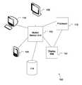
- FIG. 1Aillustrates an exemplary system configured to implement motion capture and analysis.
- system 100includes motion sensor unit 102 , display mat 104 , portable display 106 , display 108 , terminal 110 , processor 112 , and database 114 .
- motion sensor unit 102may be coupled, directly or indirectly, to a golf club, bat, racket, or other implement that may be used in a physical activity such as golf, baseball, tennis, or the like.
- Motion sensor unit 102may include various types of devices or units (e.g., software, hardware, circuitry, or a combination thereof) for motion measurement (e.g., accelerometer, gyroscope, and others) may be used to gather data associated with the motion of a given implement that is processed using system 100 .
- devices or unitse.g., software, hardware, circuitry, or a combination thereof
- motion measuremente.g., accelerometer, gyroscope, and others
- datamay be transmitted from motion sensor unit 102 to display units (e.g., portable display 106 , display 108 , terminal 110 , or others), processor 112 , or devices that may be configured to use, analyze, evaluate, transform, or perform other operations on data from motion sensor unit 102 .
- Display 108may be implemented using a liquid crystal display (LCD), projection tube television, digital television, or any type of analog or digital display.
- LCDliquid crystal display
- display 108may receive data for display using various types of wireless, wired, optical, acoustic, or other video data transmission protocols (e.g., S-video, high definition multimedia interface (HDMI), or others).
- HDMIhigh definition multimedia interface
- a wireless receiving unitmay be coupled to display 108 and used to receive data from motion sensor unit 102 , processor 112 , display mat 104 , or other elements.
- processor 112may be implemented as an element of a wireless receiving unit (not shown) coupled to display 108 in order to process data for generating and rendering an image or video on display 108 .
- a wireless receiving unit(not shown) may be referred to as a sensor pod or dongle (“dongle”) and, when coupled to display 108 , process data received from motion sensor unit 102 in order to generate and render an image for display.
- the above-described techniquesmay be used to provide data processing capabilities of data received from motion sensor unit 102 and rendered on display 108 , terminal 110 , or other types of displays not shown. Still further, data may be transmitted from motion sensor unit 102 , received by a dongle (not shown), and processed, rendered, and displayed in real-time or substantially real-time on display 108 .
- system 100 and the above-described elementsmay be varied in design, function, structure, configuration, implementation, or other aspects and are not limited to the examples described.
- processor 112may be used to process data provided by motion sensor unit 102 in order to generate a display on, for example, portable display unit 106 or display mat 104 .
- processor 112may be implemented in a separate device or in connection with motion sensor unit 102 , display mat 104 , portable display 106 , display 108 , terminal 110 , or any other type of device including, for example, a television (TV), monitor, display, or other type of device.
- motion sensor unit 102may be coupled to a golf club (not shown) and, when the golf club is swung, data may be captured by motion sensor unit 102 and transmitted to processor 112 using, for example, a wireless transmitter, transceiver, or the like (not shown).
- processor 112may be implemented within a dongle or other type of wireless receiver coupled to display 108 .
- images or video of motion captured by motion sensor unit 102may be recorded and/or processed to display an image or video on display 108 .
- processor 112may be implemented as part of display 108 without the use of a dongle or other wireless sensor pod coupled externally to display 108 .
- database 114may be implemented to store and retrieve data associated with motion (e.g., swinging motion of a golf club, bat, racket, or the like) captured by motion sensor unit 102 .
- a golfermay wish to configure processor 112 to record and store data associated with a series of swings in database 114 , which may be implemented using a standalone or distributed database, repository, data warehouse, storage area network (SAN), network attached storage, or other type of data storage facility using hardware and/or software. Further, once stored, data may be retrieved from database 114 , which may be implemented with one, some, or none of the other elements shown in system 100 . In other words, database 114 may be implemented with processor 112 with display 108 . Database 114 may also be implemented with one or more of motion sensor unit 102 , display mat 104 , portable display unit 106 , display 108 , terminal 110 , processor 112 , or other elements (not shown). In some examples, data from motion sensor unit 102 may be transmitted to display mat 104 , portable display unit 106 , display 108 , or terminal 110 using one or more wireless, wired, optical, acoustic, or other types of data communication links or protocols.
- display mat 104may be configured to generate, render, and display an image on its surface.
- Display mat 104may be configured for display on a horizontal, vertical, angled, or other type of surface.
- display mat 104be mounted on a vertical surface and used to display an image associated with a golf club, baseball bat, cricket bat, polo mallet, or others.
- Display mat 104may also be configured to lie or be mounted to a horizontal surface (e.g., floor, ground, or the like) and used to present an image associated with motion under evaluation. Data for various types of motion may be evaluated and presented using the techniques described herein.
- motion associated with a portion of a bodymay be evaluated by system 100 , including detecting motion using motion sensor unit 102 , which is processed by processor 112 and stored in database 114 and/or presented on display mat 104 , the latter of which may be implemented using various types of displays (e.g., mats, screens, upright displays, liquid crystal displays, and others without limitation).
- types of motionthat may be evaluated include movement by a boxer's punching motion, a pitcher's baseball-throwing motion, a football player's kicking motion (e.g., a punt), running motion, combat or martial arts-related hand and foot motion, a dancer's foot, arm, or other body motion, and others.
- display mat 104when data is transmitted from motion sensor unit 102 , an image of a golf club head being swung may be generated on display mat 104 .
- display mat 104may use various types of display resolution techniques and is not limited to any particular implementation.
- display mat 104may be implemented using a flexible LCD, active matrix, thin film transistor (TFT), or other types of display technologies.
- portable display 106 , display 108 , and terminal 110may be used to display data generated by motion sensor unit 102 , stored and retrieved from database 114 , or processed by processor 112 .
- Links provided by and between elements 102 - 112may be implemented as unidirectional, bidirectional, or other types of data communication links.
- the number, type, configuration, and topology of system 100 , motion sensor unit 102 , display mat 104 , portable display 106 , display 108 , terminal 110 , and processor 112may be varied and are not limited to the descriptions provided.
- FIG. 1Billustrates an alternative exemplary system.
- system 120includes display 108 , processor 112 , dongle 122 , and data connection 124 .
- dongle 122may be implemented as a wireless transceiver to receive and/or send data from processor 112 over data connection 124 , which may be implemented using wired, wireless, optical, acoustic, or other types of data communication protocols.
- dongle 122may be implemented using a wired data connection (not shown) in order to receive data for generating, rendering, and displaying an image on display 108 .
- processor 112may be implemented as part of dongle 122 .
- system 120and the above-described elements may be varied in implementation, function, structure, or other aspects and are not limited to the examples provided above.
- FIG. 1Cillustrates another alternative exemplary system.
- system 130includes motion sensor unit 102 , display mat 104 , display 108 , processor 112 , database 114 , dongle 122 , and data connection 124 , which may be implemented as described above or differently.
- application 132may include motion sensor unit 102 , display mat 104 , processor 112 , and database 114 , which may be implemented as described above or differently. Further, application 132 may be implemented using a standalone, distributed, or other type of application architecture or topology.
- one or more elementse.g., motion sensor unit 102 , display mat 104 , processor 112 , database 114 , or others
- application 132may be implemented apart from or as part of dongle 122 or display 108 .
- system 130 and the above-described elementsmay be varied in implementation, function, or structure and are not limited to the descriptions provided.
- FIG. 2Aillustrates an exemplary application architecture configured to implement motion capture and analysis.
- motion sensor unit 200includes triple axis accelerometer 210 , triple axis gyroscope 212 , low pass filtering 214 , low pass filtering 216 , analog to digital converter 218 , parallel to series converter 220 , wireless modem 222 and wireless transceiver 224 .
- motion sensor unit 200may include a micro-controller (not shown) similar to micro-controller 256 (described below in connection with FIG. 2B ).
- motion sensor unit 200may be detachably coupled to an object (e.g., golf club, tennis racket, baseball bat, softball bat, hockey stick, other sporting equipment, or others).
- Motion sensor unit 200may be various sizes and shapes to accommodate a static and secure attachment to the various shapes and sizes of the detachably coupled object.
- Motion sensor unit 200may have an adjustable attachment mechanism to enable one unit to accommodate various shapes and sizes of attached objects.
- Motion sensor unit 200may be lightweight and easily portable. Motion sensor unit 200 may be easily attached or detached from the object by the user, without the need for specialized tools or accessories.
- motion sensor unit 200 and the above-described elementsmay be implemented differently and are not limited to the descriptions provided.
- a power supplysuch as a battery or external AC/DC converter may be coupled to motion sensor unit 200 .
- Power suppliesmay be implemented as rechargeable, non-rechargeable, portable, or disposable batteries.
- a battery(not shown) may be implemented as part of motion sensor unit 200 , supplying power to motion sensor unit 200 and its associated components.
- a power sourcemay be implemented as another attachment to motion sensor unit 200 .
- triple axis accelerometer 210 and triple axis gyroscope 212may be configured to measure movement of an object (e.g., golf club, tennis racket, baseball bat, softball bat, hockey stick, other sporting equipment, or others).
- triple axis accelerometer 210 and triple axis gyroscope 212may be a micro electro-mechanical system (MEMS) device.
- MEMSmicro electro-mechanical system
- triple axis accelerometer 210 and triple axis gyroscope 212may be an analog or digital device.
- triple axis accelerometer 210may be configured to measure the acceleration of the object along the x-axis
- y-axis and z-axis and triple axis gyroscope 212may be configured to measure the rotational movement of the object along the planar, orthogonal and axial directions.
- triple axis accelerometer 210 and triple axis gyroscope 212may be configured differently and are not limited to the descriptions provided.
- triple axis accelerometer 210communicates the data signal to low pass filtering 214 and triple axis gyroscope 212 communicates the data signal to low pass filtering 216 . Further, low pass filtering 214 and low pass filtering 216 communicate the data signal to analog to digital converter 218 .
- analog to digital converter 218may be configured to convert the data from an analog signal to a digital signal.
- analog to digital converter 218communicates the data signal to parallel to series converter 220 . In some examples, parallel to series converter 220 is configured to convert the data signal from a parallel electrical signal to a series electrical signal.
- Wireless modem 222is coupled to wireless transceiver 224 for sending and receiving signals (e.g., RF) between motion sensor unit 200 and display unit (described below in connection with FIG. 2B ).
- wireless transceiver 224may be configured to send and receive communication signals using various wireless formats (e.g., ZigBee (i.e., IEEE 802.15.4 data communication protocol/standard/specification), radio frequency (RF) waves, IEEE 802.11, Bluetooth, UHF, or others).
- ZigBeei.e., IEEE 802.15.4 data communication protocol/standard/specification
- RFradio frequency
- FIG. 2Bfurther illustrates an exemplary application architecture configured to implement motion capture and analysis.
- processing and display unit 250includes wireless modem 254 , wireless transceiver 252 , micro-controller 256 , display driver 258 , path driver 260 , info driver 262 and user interface 264 .
- processing and display unit 250may be a remote device or system (e.g., display mat, portable display device, television monitor, computer, server, video recorder, or others) configured to present or display visual, graphical or numerical data measured by the motion sensor unit (described above in connection with FIG. 2A ) and values associated with object movement, which are calculated using the measured data.
- a remote device or systeme.g., display mat, portable display device, television monitor, computer, server, video recorder, or others
- processing and display unit 250may be configured to save the graphic and numerical data and values associated with a user selected reference point (i.e., “best swing”) for comparison with subsequent iterations of the object movement. In some examples, processing and display unit 250 may be configured to provide an acoustic indication or response. Processing and display unit 250 may be configured with a memory device (not shown here). The memory device may be a permanent or removable memory card or hard drive.
- processing and display unit 250presents various parameters associated with the motion of an object such as measured data (e.g., three dimensional acceleration, three dimensional rotational acceleration, maximum acceleration, or others) or calculated values (e.g., three dimensional velocity, three dimensional rotational velocity, location coordinates, maximum velocity, impact velocity, relative angle of object at point of impact, or others). Still further, processing and display unit 250 may be configured to graphically present a directional path representing the actual movement of an object and graphically indicate various significant points of reference (e.g., point of maximum velocity, or others) along the object's path of movement. In other examples, processing and display unit 250 may be configured to present or display any number of different visual, graphical or numerical parameters associated with the movement of an object and are not limited to the descriptions provided.
- measured datae.g., three dimensional acceleration, three dimensional rotational acceleration, maximum acceleration, or others
- calculated valuese.g., three dimensional velocity, three dimensional rotational velocity, location coordinates, maximum velocity, impact velocity, relative angle of object at point of
- processing and display unit 250may be a display mat for use on a horizontal and flat surface, which display mat may be various sizes, shapes or dimensions.
- a display mat(e.g., display mat 104 ( FIG. 1A )) may be configured such that the user stands on the mat while moving the object, or stands adjacent to the mat while moving the object.
- a display matmay also be made of a material that is durable, impact resistant and able to sustain the weight of a person.
- a display matmay be made of a material that is easily rolled up and lightweight for easy portability.
- a display matmay be made of an array of surface mounted light emitting devices (LEDs).
- the display matmay be configured to present or display any or all of the visual, graphic or numerical parameters discussed above.
- processing and display unit 250may be implemented differently and is not limited to the descriptions provided.
- processing and display unit 250may be a portable display device for handheld use.
- a portable display devicemay be small, lightweight and easily transported by the user.
- a portable display devicemay be various sizes, shapes or dimensions.
- a portable display devicemay also be configured to present or display any or all of the visual, graphic or numerical parameters discussed above.
- processing and display unit 250 as a portable display devicemay be implemented differently and is not limited to the descriptions provided.
- a power supplysuch as a battery or external AC/DC converter may be coupled to processing and display unit 250 .
- Power suppliesmay be implemented as rechargeable, non-rechargeable, portable, or disposable batteries.
- a battery(not shown) may be implemented as part of processing and display unit 250 , supplying power to processing and display unit 250 and its associated components.
- a power sourcemay be implemented as another attachment to processing and display unit 250 .
- wireless modem 254is coupled to wireless transceiver 252 for sending and receiving signals (e.g., RF) between processing and display unit 250 and motion sensor unit 200 (described above in connection with FIG. 2A ).
- wireless transceiver 252may be configured to send and receive communication signals using various wireless formats (e.g., ZigBee, RF waves, IEEE 802.11, Bluetooth, UHF, or others).
- wireless modem 254communicates the data signal to micro-controller 256 .
- micro-controller 256is configured to process the measured data captured by motion sensor unit 200 (described above in connection with FIG. 2A ).
- Micro-controller 256may calculate values associated with movement of an object (e.g., three dimensional velocity, three dimensional rotational velocity, location coordinates, maximum velocity, impact velocity, relative angle of object at point of impact, or others) using the movement data captured by motion sensor unit 200 (described above in connection with FIG. 2A ).
- micro-controller 256communicates a position data signal to display driver 258 and swing position data to info driver 262 .
- display driver 258communicates the position data to path driver 260 .
- path driver 260 and info driver 262communicate the position and swing position data to and from user interface 264 .
- user interface 264may be configured to include user controls which allow user configuration of the system.
- User interface 264 controlsmay include various input mechanism and allow the user to save a selected reference point (i.e., “best swing”) or select the desired display parameters.
- user interface 264may be configured to include an acoustic signal to provide an auditory indication.
- user interface 264may be configured differently and is not limited to the descriptions provided. Still further, processing and display unit 250 and the above-described elements may be implemented differently and is not limited to the descriptions or examples provided above.
- FIG. 3Aillustrates an exemplary motion sensor unit.
- a top view of an exemplary user of the motion sensor unitis shown.
- motion sensor unit 300impact object 302 , movement object 304 , axial rotation 306 , planar rotation 308 , x-axis 320 and y axis 322 are shown.
- Motion sensor unit 300may be configured and implemented as described above as motion sensor unit 200 (described above in connection with FIG. 2A ). As shown here, motion sensor unit 300 may be used to measure and capture axial rotation 306 , planar rotation 308 , x-axis acceleration along x-axis 320 and y-axis acceleration along y-axis 322 . In other examples, motion sensor unit 300 may be configured to measure and capture other parameters associated with movement of an object and is not limited by the descriptions provided.
- motion sensor 300is coupled to movement object 304 , as shown here as a golf club.
- movement object 304may be a tennis racket, baseball bat, softball bat, hockey stick, other sporting equipment, or other moveable object.
- movement object 304is intended to make dynamic contact with impact object 302 , as shown here as a golf ball.
- impact object 302may be a baseball, softball, hockey puck, or other moving object.
- movement object 304 and impact object 302may be different and are not limited to the descriptions provided.
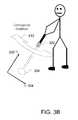
- FIG. 3Billustrates a further exemplary motion sensor unit.
- a side view of an exemplary user of the motion sensor unitis shown.
- motion sensor unit 300movement object 304 , orthogonal rotation 310 , x-axis 320 and z-axis 324 are shown.
- Motion sensor unit 300may be configured and implemented as described above as motion sensor unit 200 (described above in connection with FIG. 2A ). As shown here, motion sensor unit 300 may be used to measure and capture orthogonal rotation 310 , x-axis acceleration along x-axis 320 and z-axis acceleration along z-axis 324 . In other examples, motion sensor unit 300 may be configured to measure and capture other parameters associated with movement of an object and is not limited by the descriptions provided.
- motion sensor 300is coupled to movement object 304 , as shown here as a golf club.
- movement object 304may be a tennis racket, baseball bat, softball bat, hockey stick, other sporting equipment, or other moveable object.
- movement object 304is intended to make dynamic contact with impact object (not shown).
- movement object 304may be different and is not limited to the descriptions provided.
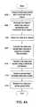
- FIG. 4Aillustrates an exemplary process for motion capture and analysis.
- data associated with movement of an objectmay be captured ( 402 ).
- the datamay be processed to determine values associated with movement of the object ( 404 ).
- the data and the valuesmay be stored ( 406 ).
- the data and valuesmay be converted from analog to digital for a wireless transmission ( 408 ).
- the data and the valuesmay be transmitted using a wireless connection ( 410 ).
- a wireless modemFIG. 2B
- FIG. 2Bconfigured to modulate or demodulate transmitted data for processing and presentation on a display (e.g., display 108 ( FIGS. 1A-1C ) ( 412 ).
- the data and valuesmay be presented graphically ( 414 ).
- the above-described processmay be varied in function, processes and performed in any arbitrary order and is not limited to the examples shown and described.
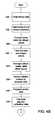
- FIG. 4B and FIG. 4Cillustrate an alternative exemplary process for motion capture and analysis.
- binary datamay be read ( 420 ).
- the framemay be split into 6 sensor channels ( 422 ).
- the binary datamay be converted into integer values ( 424 ).
- the data and integer valuesmay be filtered ( 426 ).
- a “swing started” calculationmay be performed (not shown) to determine when a swinging motion begins.
- a “swing started” calculation or determinationmay be performed, in some examples, after filtering data and integer values.
- an optional operation for creating a lapsed time indexmay also be created (not shown).
- the datamay be averaged to create initial offset values ( 432 ).
- Relative rotationmay be converted to absolute data ( 434 ).
- the sensor datamay be integrated ( 436 ).
- the adjusted calibration datamay be calculated ( 438 ).
- Relative datamay be converted to absolute data ( 440 ).
- a velocity calculationmay be performed ( 442 ).
- a velocity clamping calculationmay be performed ( 444 ).
- a “swing end” calculationmay be performed to determine when a swing motion ends or terminates ( 446 ).
- Velocity datamay be integrated to determine location ( 448 ).
- Location datamay be translated to object head ( 450 ).
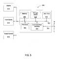
- FIG. 5illustrates an exemplary computer system suitable to implement motion capture and analysis.
- computer system 500may be used to implement computer programs, applications, methods, processes, or other software to perform the above-described techniques.
- Computer system 500includes a bus 502 or other communication mechanism for communicating information, which interconnects subsystems and devices, such as processor 504 , system memory 506 (e.g., RAM), storage device 508 (e.g., ROM), disk drive 510 (e.g., magnetic or optical), communication interface 512 (e.g., modem or Ethernet card), display 514 (e.g., CRT or LCD), input device 516 (e.g., keyboard), and output control 518 .
- processor 504system memory 506 (e.g., RAM), storage device 508 (e.g., ROM), disk drive 510 (e.g., magnetic or optical), communication interface 512 (e.g., modem or Ethernet card), display 514 (e.g., CRT or LCD), input device 516 (e.
- computer system 500performs specific operations by processor 504 executing one or more sequences of one or more instructions stored in system memory 506 . Such instructions may be read into system memory 506 from another computer readable medium, such as static storage device 508 or disk drive 510 . In some examples, hard-wired circuitry may be used in place of or in combination with software instructions for implementation.
- Non-volatile mediaincludes, for example, optical or magnetic disks, such as disk drive 510 .
- Volatile mediaincludes dynamic memory, such as system memory 506 .
- Computer readable mediaincludes, for example, floppy disk, flexible disk, hard disk, magnetic tape, any other magnetic medium, CD-ROM, any other optical medium, punch cards, paper tape, any other physical medium with patterns of holes, RAM, PROM, EPROM, FLASH-EPROM, any other memory chip or cartridge, or any other medium from which a computer can read.
- Transmission mediummay include any tangible or intangible medium that is capable of storing, encoding or carrying instructions for execution by the machine, and includes digital or analog communications signals or other intangible medium to facilitate communication of such instructions.
- Transmission mediaincludes coaxial cables, copper wire, and fiber optics, including wires that comprise bus 502 for transmitting a computer data signal.
- execution of the sequences of instructionsmay be performed by a single computer system 500 .
- two or more computer systems 500 coupled by communication link 520may perform the sequence of instructions in coordination with one another.
- Computer system 500may transmit and receive messages, data, and instructions, including program, i.e., application code, through communication link 520 and communication interface 512 .
- Received program codemay be executed by processor 504 as it is received, and/or stored in disk drive 510 , or other non-volatile storage for later execution.
Landscapes
- Health & Medical Sciences (AREA)
- General Health & Medical Sciences (AREA)
- Physical Education & Sports Medicine (AREA)
- Physics & Mathematics (AREA)
- General Physics & Mathematics (AREA)
- User Interface Of Digital Computer (AREA)
Abstract
Description
Claims (20)
Priority Applications (5)
| Application Number | Priority Date | Filing Date | Title |
|---|---|---|---|
| US13/972,908US8831905B2 (en) | 2008-08-19 | 2013-08-22 | Motion capture and analysis |
| US14/461,659US9656122B2 (en) | 2008-08-19 | 2014-08-18 | Motion capture and analysis |
| US15/601,812US10434367B2 (en) | 2008-08-19 | 2017-05-22 | Motion capture and analysis |
| US16/588,832US10870037B2 (en) | 2008-08-19 | 2019-09-30 | Motion capture and analysis |
| US17/129,491US20210346760A1 (en) | 2008-08-19 | 2020-12-21 | Motion capture and analysis |
Applications Claiming Priority (2)
| Application Number | Priority Date | Filing Date | Title |
|---|---|---|---|
| US12/194,450US8589114B2 (en) | 2008-08-19 | 2008-08-19 | Motion capture and analysis |
| US13/972,908US8831905B2 (en) | 2008-08-19 | 2013-08-22 | Motion capture and analysis |
Related Parent Applications (1)
| Application Number | Title | Priority Date | Filing Date |
|---|---|---|---|
| US12/194,450ContinuationUS8589114B2 (en) | 2008-08-19 | 2008-08-19 | Motion capture and analysis |
Related Child Applications (1)
| Application Number | Title | Priority Date | Filing Date |
|---|---|---|---|
| US14/461,659ContinuationUS9656122B2 (en) | 2008-08-19 | 2014-08-18 | Motion capture and analysis |
Publications (2)
| Publication Number | Publication Date |
|---|---|
| US20140032162A1 US20140032162A1 (en) | 2014-01-30 |
| US8831905B2true US8831905B2 (en) | 2014-09-09 |
Family
ID=41697158
Family Applications (6)
| Application Number | Title | Priority Date | Filing Date |
|---|---|---|---|
| US12/194,450Expired - Fee RelatedUS8589114B2 (en) | 2008-08-19 | 2008-08-19 | Motion capture and analysis |
| US13/972,908ActiveUS8831905B2 (en) | 2008-08-19 | 2013-08-22 | Motion capture and analysis |
| US14/461,659Expired - Fee RelatedUS9656122B2 (en) | 2008-08-19 | 2014-08-18 | Motion capture and analysis |
| US15/601,812Active2029-02-23US10434367B2 (en) | 2008-08-19 | 2017-05-22 | Motion capture and analysis |
| US16/588,832ActiveUS10870037B2 (en) | 2008-08-19 | 2019-09-30 | Motion capture and analysis |
| US17/129,491AbandonedUS20210346760A1 (en) | 2008-08-19 | 2020-12-21 | Motion capture and analysis |
Family Applications Before (1)
| Application Number | Title | Priority Date | Filing Date |
|---|---|---|---|
| US12/194,450Expired - Fee RelatedUS8589114B2 (en) | 2008-08-19 | 2008-08-19 | Motion capture and analysis |
Family Applications After (4)
| Application Number | Title | Priority Date | Filing Date |
|---|---|---|---|
| US14/461,659Expired - Fee RelatedUS9656122B2 (en) | 2008-08-19 | 2014-08-18 | Motion capture and analysis |
| US15/601,812Active2029-02-23US10434367B2 (en) | 2008-08-19 | 2017-05-22 | Motion capture and analysis |
| US16/588,832ActiveUS10870037B2 (en) | 2008-08-19 | 2019-09-30 | Motion capture and analysis |
| US17/129,491AbandonedUS20210346760A1 (en) | 2008-08-19 | 2020-12-21 | Motion capture and analysis |
Country Status (1)
| Country | Link |
|---|---|
| US (6) | US8589114B2 (en) |
Cited By (22)
| Publication number | Priority date | Publication date | Assignee | Title |
|---|---|---|---|---|
| US20160107027A1 (en)* | 2008-08-19 | 2016-04-21 | Angelo Gregory Papadourakis | Motion capture and analysis |
| US10109061B2 (en) | 2010-08-26 | 2018-10-23 | Blast Motion Inc. | Multi-sensor even analysis and tagging system |
| US10124230B2 (en) | 2016-07-19 | 2018-11-13 | Blast Motion Inc. | Swing analysis method using a sweet spot trajectory |
| US10133919B2 (en) | 2010-08-26 | 2018-11-20 | Blast Motion Inc. | Motion capture system that combines sensors with different measurement ranges |
| US10265602B2 (en) | 2016-03-03 | 2019-04-23 | Blast Motion Inc. | Aiming feedback system with inertial sensors |
| US10339978B2 (en) | 2010-08-26 | 2019-07-02 | Blast Motion Inc. | Multi-sensor event correlation system |
| US10350455B2 (en) | 2010-08-26 | 2019-07-16 | Blast Motion Inc. | Motion capture data fitting system |
| US10406399B2 (en) | 2010-08-26 | 2019-09-10 | Blast Motion Inc. | Portable wireless mobile device motion capture data mining system and method |
| US10427017B2 (en) | 2014-05-20 | 2019-10-01 | Arccos Golf Llc | System and method for monitoring performance characteristics associated with user activities involving swinging instruments |
| US10565888B2 (en) | 2013-02-17 | 2020-02-18 | Ronald Charles Krosky | Instruction production |
| US10589161B2 (en) | 2015-07-21 | 2020-03-17 | Arccos Golf, Llc | System and method for monitoring performance characteristics associated with user activities involving swinging instruments |
| US10610732B2 (en) | 2011-08-29 | 2020-04-07 | Icuemotion Llc | Inertial sensor motion tracking and stroke analysis system |
| US10617926B2 (en) | 2016-07-19 | 2020-04-14 | Blast Motion Inc. | Swing analysis method using a swing plane reference frame |
| US10668353B2 (en) | 2014-08-11 | 2020-06-02 | Icuemotion Llc | Codification and cueing system for sport and vocational activities |
| US10682562B2 (en) | 2017-01-17 | 2020-06-16 | Arccos Golf Llc | Autonomous personalized golf recommendation and analysis environment |
| US10786728B2 (en) | 2017-05-23 | 2020-09-29 | Blast Motion Inc. | Motion mirroring system that incorporates virtual environment constraints |
| US10854104B2 (en) | 2015-08-28 | 2020-12-01 | Icuemotion Llc | System for movement skill analysis and skill augmentation and cueing |
| US11565163B2 (en) | 2015-07-16 | 2023-01-31 | Blast Motion Inc. | Equipment fitting system that compares swing metrics |
| US11577142B2 (en) | 2015-07-16 | 2023-02-14 | Blast Motion Inc. | Swing analysis system that calculates a rotational profile |
| US11833406B2 (en) | 2015-07-16 | 2023-12-05 | Blast Motion Inc. | Swing quality measurement system |
| US11990160B2 (en) | 2015-07-16 | 2024-05-21 | Blast Motion Inc. | Disparate sensor event correlation system |
| US12172066B2 (en) | 2017-01-17 | 2024-12-24 | Arccos Golf Llc | Autonomous tracking and personalized golf recommendation and analysis environment |
Families Citing this family (104)
| Publication number | Priority date | Publication date | Assignee | Title |
|---|---|---|---|---|
| US7771320B2 (en)* | 2006-09-07 | 2010-08-10 | Nike, Inc. | Athletic performance sensing and/or tracking systems and methods |
| US8430770B2 (en) | 2006-10-07 | 2013-04-30 | Brian M. Dugan | Systems and methods for measuring and/or analyzing swing information |
| US8337335B2 (en) | 2006-10-07 | 2012-12-25 | Dugan Brian M | Systems and methods for measuring and/or analyzing swing information |
| US9084925B2 (en)* | 2008-10-09 | 2015-07-21 | Golf Impact, Llc | Golf swing analysis apparatus and method |
| US20120046119A1 (en)* | 2008-10-09 | 2012-02-23 | Golf Impact Llc | Golf Swing Measurement and Analysis System |
| US9604118B2 (en) | 2008-10-09 | 2017-03-28 | Golf Impact, Llc | Golf club distributed impact sensor system for detecting impact of a golf ball with a club face |
| US9149693B2 (en) | 2009-01-20 | 2015-10-06 | Nike, Inc. | Golf club and golf club head structures |
| US9192831B2 (en) | 2009-01-20 | 2015-11-24 | Nike, Inc. | Golf club and golf club head structures |
| US8668595B2 (en) | 2011-04-28 | 2014-03-11 | Nike, Inc. | Golf clubs and golf club heads |
| GB0901020D0 (en)* | 2009-01-21 | 2009-03-04 | Birmingham City University | A motion capture apparatus |
| US8564613B2 (en)* | 2009-06-05 | 2013-10-22 | Nonin Medical, Inc. | Display modification based on measurement type |
| US9028337B2 (en) | 2010-08-26 | 2015-05-12 | Blast Motion Inc. | Motion capture element mount |
| US9235765B2 (en) | 2010-08-26 | 2016-01-12 | Blast Motion Inc. | Video and motion event integration system |
| US9052201B2 (en) | 2010-08-26 | 2015-06-09 | Blast Motion Inc. | Calibration system for simultaneous calibration of multiple motion capture elements |
| US8465376B2 (en) | 2010-08-26 | 2013-06-18 | Blast Motion, Inc. | Wireless golf club shot count system |
| US10254139B2 (en) | 2010-08-26 | 2019-04-09 | Blast Motion Inc. | Method of coupling a motion sensor to a piece of equipment |
| US8827824B2 (en) | 2010-08-26 | 2014-09-09 | Blast Motion, Inc. | Broadcasting system for broadcasting images with augmented motion data |
| US9619891B2 (en) | 2010-08-26 | 2017-04-11 | Blast Motion Inc. | Event analysis and tagging system |
| US8941723B2 (en) | 2010-08-26 | 2015-01-27 | Blast Motion Inc. | Portable wireless mobile device motion capture and analysis system and method |
| US9401178B2 (en) | 2010-08-26 | 2016-07-26 | Blast Motion Inc. | Event analysis system |
| US8944928B2 (en) | 2010-08-26 | 2015-02-03 | Blast Motion Inc. | Virtual reality system for viewing current and previously stored or calculated motion data |
| US8613676B2 (en) | 2010-08-26 | 2013-12-24 | Blast Motion, Inc. | Handle integrated motion capture element mount |
| US9646209B2 (en) | 2010-08-26 | 2017-05-09 | Blast Motion Inc. | Sensor and media event detection and tagging system |
| US8702516B2 (en) | 2010-08-26 | 2014-04-22 | Blast Motion Inc. | Motion event recognition system and method |
| US8903521B2 (en)* | 2010-08-26 | 2014-12-02 | Blast Motion Inc. | Motion capture element |
| US9622361B2 (en) | 2010-08-26 | 2017-04-11 | Blast Motion Inc. | Enclosure and mount for motion capture element |
| US9643049B2 (en) | 2010-08-26 | 2017-05-09 | Blast Motion Inc. | Shatter proof enclosure and mount for a motion capture element |
| US9039527B2 (en) | 2010-08-26 | 2015-05-26 | Blast Motion Inc. | Broadcasting method for broadcasting images with augmented motion data |
| US9076041B2 (en) | 2010-08-26 | 2015-07-07 | Blast Motion Inc. | Motion event recognition and video synchronization system and method |
| US9320957B2 (en) | 2010-08-26 | 2016-04-26 | Blast Motion Inc. | Wireless and visual hybrid motion capture system |
| US9406336B2 (en) | 2010-08-26 | 2016-08-02 | Blast Motion Inc. | Multi-sensor event detection system |
| US9033810B2 (en) | 2010-08-26 | 2015-05-19 | Blast Motion Inc. | Motion capture element mount |
| US9418705B2 (en) | 2010-08-26 | 2016-08-16 | Blast Motion Inc. | Sensor and media event detection system |
| US9940508B2 (en) | 2010-08-26 | 2018-04-10 | Blast Motion Inc. | Event detection, confirmation and publication system that integrates sensor data and social media |
| US8994826B2 (en) | 2010-08-26 | 2015-03-31 | Blast Motion Inc. | Portable wireless mobile device motion capture and analysis system and method |
| US8905855B2 (en) | 2010-08-26 | 2014-12-09 | Blast Motion Inc. | System and method for utilizing motion capture data |
| US9247212B2 (en)* | 2010-08-26 | 2016-01-26 | Blast Motion Inc. | Intelligent motion capture element |
| US9746354B2 (en) | 2010-08-26 | 2017-08-29 | Blast Motion Inc. | Elastomer encased motion sensor package |
| US8696482B1 (en) | 2010-10-05 | 2014-04-15 | Swingbyte, Inc. | Three dimensional golf swing analyzer |
| US9211439B1 (en) | 2010-10-05 | 2015-12-15 | Swingbyte, Inc. | Three dimensional golf swing analyzer |
| US12340889B2 (en)* | 2010-11-05 | 2025-06-24 | Nike, Inc. | User interface for remote joint workout session |
| US9457256B2 (en) | 2010-11-05 | 2016-10-04 | Nike, Inc. | Method and system for automated personal training that includes training programs |
| US9283429B2 (en) | 2010-11-05 | 2016-03-15 | Nike, Inc. | Method and system for automated personal training |
| US9852271B2 (en) | 2010-12-13 | 2017-12-26 | Nike, Inc. | Processing data of a user performing an athletic activity to estimate energy expenditure |
| US9977874B2 (en) | 2011-11-07 | 2018-05-22 | Nike, Inc. | User interface for remote joint workout session |
| CN103282907A (en) | 2010-11-05 | 2013-09-04 | 耐克国际有限公司 | Method and system for automated personal training |
| US9687705B2 (en) | 2010-11-30 | 2017-06-27 | Nike, Inc. | Golf club head or other ball striking device having impact-influencing body features |
| EP2646122B1 (en) | 2010-11-30 | 2015-03-18 | NIKE Innovate C.V. | Golf club heads or other ball striking devices having distributed impact response and a stiffened face plate |
| US10420982B2 (en) | 2010-12-13 | 2019-09-24 | Nike, Inc. | Fitness training system with energy expenditure calculation that uses a form factor |
| US20120244969A1 (en) | 2011-03-25 | 2012-09-27 | May Patents Ltd. | System and Method for a Motion Sensing Device |
| US9375624B2 (en) | 2011-04-28 | 2016-06-28 | Nike, Inc. | Golf clubs and golf club heads |
| US9409073B2 (en) | 2011-04-28 | 2016-08-09 | Nike, Inc. | Golf clubs and golf club heads |
| US8986130B2 (en) | 2011-04-28 | 2015-03-24 | Nike, Inc. | Golf clubs and golf club heads |
| US9433845B2 (en) | 2011-04-28 | 2016-09-06 | Nike, Inc. | Golf clubs and golf club heads |
| US9925433B2 (en) | 2011-04-28 | 2018-03-27 | Nike, Inc. | Golf clubs and golf club heads |
| US9433844B2 (en) | 2011-04-28 | 2016-09-06 | Nike, Inc. | Golf clubs and golf club heads |
| US9409076B2 (en) | 2011-04-28 | 2016-08-09 | Nike, Inc. | Golf clubs and golf club heads |
| US8911309B1 (en) | 2011-08-17 | 2014-12-16 | John Harihar | Batting sleeve sensor systems |
| CN107583254B (en) | 2011-08-23 | 2020-03-27 | 耐克创新有限合伙公司 | Golf club head with cavity |
| US10213645B1 (en) | 2011-10-03 | 2019-02-26 | Swingbyte, Inc. | Motion attributes recognition system and methods |
| US9811639B2 (en) | 2011-11-07 | 2017-11-07 | Nike, Inc. | User interface and fitness meters for remote joint workout session |
| US8913134B2 (en) | 2012-01-17 | 2014-12-16 | Blast Motion Inc. | Initializing an inertial sensor using soft constraints and penalty functions |
| US9409068B2 (en) | 2012-05-31 | 2016-08-09 | Nike, Inc. | Adjustable golf club and system and associated golf club heads and shafts |
| US9053256B2 (en) | 2012-05-31 | 2015-06-09 | Nike, Inc. | Adjustable golf club and system and associated golf club heads and shafts |
| CN104508669B (en) | 2012-06-04 | 2019-10-01 | 耐克创新有限合伙公司 | A system and method for integrating fitness-competitive scores |
| US9588582B2 (en) | 2013-09-17 | 2017-03-07 | Medibotics Llc | Motion recognition clothing (TM) with two different sets of tubes spanning a body joint |
| US8700354B1 (en) | 2013-06-10 | 2014-04-15 | Blast Motion Inc. | Wireless motion capture test head system |
| US20150057111A1 (en)* | 2013-08-20 | 2015-02-26 | Quattriuum Inc. | System, device and method for quantifying motion |
| US9507562B2 (en) | 2013-08-21 | 2016-11-29 | Navico Holding As | Using voice recognition for recording events |
| US10251382B2 (en)* | 2013-08-21 | 2019-04-09 | Navico Holding As | Wearable device for fishing |
| WO2015109442A1 (en) | 2014-01-21 | 2015-07-30 | 北京诺亦腾科技有限公司 | Multi-node motion measurement and analysis system |
| CN103759739B (en)* | 2014-01-21 | 2015-09-09 | 北京诺亦腾科技有限公司 | A kind of multimode motion measurement and analytic system |
| JP2015192686A (en)* | 2014-03-31 | 2015-11-05 | カシオ計算機株式会社 | Determining apparatus, determining method, and program |
| CN105096539A (en)* | 2014-04-28 | 2015-11-25 | 鸿富锦精密电子(郑州)有限公司 | Standardized operation training system and method |
| KR102233301B1 (en) | 2014-06-12 | 2021-03-31 | 순위안 카이화 (베이징) 테크놀로지 컴퍼니 리미티드 | Removable motion sensor embedded in a sport instrument |
| US20150367204A1 (en) | 2014-06-20 | 2015-12-24 | Nike, Inc. | Golf Club Head or Other Ball Striking Device Having Impact-Influencing Body Features |
| US9409074B2 (en) | 2014-08-27 | 2016-08-09 | Zepp Labs, Inc. | Recommending sports instructional content based on motion sensor data |
| US9449230B2 (en)* | 2014-11-26 | 2016-09-20 | Zepp Labs, Inc. | Fast object tracking framework for sports video recognition |
| US10043146B2 (en)* | 2015-02-12 | 2018-08-07 | Wipro Limited | Method and device for estimating efficiency of an employee of an organization |
| US10037504B2 (en)* | 2015-02-12 | 2018-07-31 | Wipro Limited | Methods for determining manufacturing waste to optimize productivity and devices thereof |
| US10129608B2 (en) | 2015-02-24 | 2018-11-13 | Zepp Labs, Inc. | Detect sports video highlights based on voice recognition |
| US10572735B2 (en) | 2015-03-31 | 2020-02-25 | Beijing Shunyuan Kaihua Technology Limited | Detect sports video highlights for mobile computing devices |
| US9554160B2 (en) | 2015-05-18 | 2017-01-24 | Zepp Labs, Inc. | Multi-angle video editing based on cloud video sharing |
| USD785473S1 (en) | 2015-08-04 | 2017-05-02 | Zepp Labs, Inc. | Motion sensor |
| USD797666S1 (en) | 2015-08-04 | 2017-09-19 | Zepp Labs, Inc. | Motion sensor charger |
| US9836129B2 (en) | 2015-08-06 | 2017-12-05 | Navico Holding As | Using motion sensing for controlling a display |
| US20170095717A1 (en)* | 2015-10-05 | 2017-04-06 | Sergey Simonov | Hockey training system |
| US9600717B1 (en) | 2016-02-25 | 2017-03-21 | Zepp Labs, Inc. | Real-time single-view action recognition based on key pose analysis for sports videos |
| US10097745B2 (en) | 2016-04-27 | 2018-10-09 | Zepp Labs, Inc. | Head rotation tracking device for video highlights identification |
| US10220285B2 (en) | 2016-05-02 | 2019-03-05 | Nike, Inc. | Golf clubs and golf club heads having a sensor |
| US10137347B2 (en) | 2016-05-02 | 2018-11-27 | Nike, Inc. | Golf clubs and golf club heads having a sensor |
| US10226681B2 (en) | 2016-05-02 | 2019-03-12 | Nike, Inc. | Golf clubs and golf club heads having a plurality of sensors for detecting one or more swing parameters |
| US10159885B2 (en) | 2016-05-02 | 2018-12-25 | Nike, Inc. | Swing analysis system using angular rate and linear acceleration sensors |
| KR101826837B1 (en) | 2016-08-12 | 2018-02-08 | 주식회사 골프존 | Device for calculating information on flight of ball, method for the same and recording medium recording the method readable by computing device |
| US10948577B2 (en) | 2016-08-25 | 2021-03-16 | Navico Holding As | Systems and associated methods for generating a fish activity report based on aggregated marine data |
| CN108014483B (en) | 2016-11-03 | 2022-03-08 | 财团法人工业技术研究院 | Action evaluation method and system |
| JP2018094248A (en)* | 2016-12-15 | 2018-06-21 | カシオ計算機株式会社 | Motion analysis device, motion analysis method and program |
| US20180272217A1 (en)* | 2017-02-27 | 2018-09-27 | Alexander Morrison | System and method for a game played with a raquet and a ball |
| CN107368725B (en)* | 2017-06-16 | 2020-04-10 | Oppo广东移动通信有限公司 | Iris recognition method, electronic device, and computer-readable storage medium |
| CN107349594B (en)* | 2017-08-31 | 2019-03-19 | 华中师范大学 | A kind of action evaluation method of virtual Dance System |
| CA3063935C (en)* | 2017-09-19 | 2021-01-12 | Michel Dagenais | Apparatus, system and method for body type specific golf |
| US10441848B1 (en)* | 2018-10-24 | 2019-10-15 | Anna Skhisov | System for automatic evaluation of martial arts moves |
| US12007512B2 (en) | 2020-11-30 | 2024-06-11 | Navico, Inc. | Sonar display features |
| CN116421956B (en)* | 2023-04-14 | 2025-07-15 | 河北师范大学 | Archery movement information processing method and device and upper computer |
Citations (2)
| Publication number | Priority date | Publication date | Assignee | Title |
|---|---|---|---|---|
| US7021140B2 (en)* | 2001-07-24 | 2006-04-04 | Noel C. Perkins | Electronic measurement of the motion of a moving body of sports equipment |
| US8589114B2 (en)* | 2008-08-19 | 2013-11-19 | Angelo Gregory Papadourakis | Motion capture and analysis |
Family Cites Families (43)
| Publication number | Priority date | Publication date | Assignee | Title |
|---|---|---|---|---|
| US3820133A (en)* | 1972-07-24 | 1974-06-25 | C Adorney | Teaching device |
| US3945646A (en)* | 1974-12-23 | 1976-03-23 | Athletic Swing Measurement, Inc. | Athletic swing measurement system and method |
| SU814373A1 (en) | 1979-04-26 | 1981-03-23 | Ленинградский Государственный Ор-Дена Ленина И Ордена Красного Зна-Мени Институт Физической Культурыим.П.Ф.Лесгафта | Device for measuring parameters of fencer weapon movement |
| US5062641A (en)* | 1989-09-28 | 1991-11-05 | Nannette Poillon | Projectile trajectory determination system |
| US5056783A (en) | 1989-10-18 | 1991-10-15 | Batronics, Inc. | Sports implement swing analyzer |
| US5269519A (en)* | 1990-08-15 | 1993-12-14 | David Malone | Game simulation interface apparatus and method |
| US5337758A (en) | 1991-01-11 | 1994-08-16 | Orthopedic Systems, Inc. | Spine motion analyzer and method |
| JPH0796044B2 (en)* | 1992-04-22 | 1995-10-18 | 光雄 浦 | Batting practice device |
| US5688183A (en)* | 1992-05-22 | 1997-11-18 | Sabatino; Joseph | Velocity monitoring system for golf clubs |
| US5377541A (en) | 1992-11-18 | 1995-01-03 | Patten; Richard L. | Golf club grip training assembly |
| US5447305A (en)* | 1993-02-01 | 1995-09-05 | Creative Sports Design, Inc. | Baseball batting aid for detecting motion of head in more than one axis of motion |
| US5697791A (en) | 1994-11-29 | 1997-12-16 | Nashner; Lewis M. | Apparatus and method for assessment and biofeedback training of body coordination skills critical and ball-strike power and accuracy during athletic activitites |
| US5694340A (en)* | 1995-04-05 | 1997-12-02 | Kim; Charles Hongchul | Method of training physical skills using a digital motion analyzer and an accelerometer |
| WO1997045176A1 (en) | 1996-05-30 | 1997-12-04 | Helena Laboratories Corporation | Sports training system |
| US5792000A (en)* | 1996-07-25 | 1998-08-11 | Sci Golf Inc. | Golf swing analysis method and apparatus |
| GB2318982A (en) | 1996-11-05 | 1998-05-13 | John Paul Wood | Golf club with sensors |
| US6073086A (en)* | 1998-01-14 | 2000-06-06 | Silicon Pie, Inc. | Time of motion, speed, and trajectory height measuring device |
| US5941779A (en)* | 1998-03-26 | 1999-08-24 | Zeiner-Gundersen; Dag H. | Golf club swing training device |
| US6227984B1 (en)* | 1998-05-01 | 2001-05-08 | Charles H. Blankenship | Golf swing analysis methods |
| WO2000029075A1 (en) | 1998-11-16 | 2000-05-25 | Hackman Lloyd E | Golf swing frequency analyzer |
| US6173610B1 (en)* | 1998-12-23 | 2001-01-16 | Robert L. Pace | Sports swing impact speed indicator |
| US6441745B1 (en)* | 1999-03-22 | 2002-08-27 | Cassen L. Gates | Golf club swing path, speed and grip pressure monitor |
| US6224493B1 (en) | 1999-05-12 | 2001-05-01 | Callaway Golf Company | Instrumented golf club system and method of use |
| AU2433301A (en)* | 1999-12-16 | 2001-06-25 | Fred Knecht | Apparatus and method for analyzing golf swing |
| US6474159B1 (en) | 2000-04-21 | 2002-11-05 | Intersense, Inc. | Motion-tracking |
| US20030207718A1 (en) | 2000-10-20 | 2003-11-06 | Perlmutter Michael S. | Methods and systems for analyzing the motion of sporting equipment |
| CA2364919A1 (en)* | 2000-12-14 | 2002-06-14 | Kevin Tuer | Proprioceptive golf club with analysis, correction and control capabilities |
| US20060247070A1 (en) | 2001-06-11 | 2006-11-02 | Recognition Insight, Llc | Swing position recognition and reinforcement |
| US6821211B2 (en)* | 2001-09-14 | 2004-11-23 | Golftech | Sport swing analysis system |
| US7140248B1 (en) | 2002-01-22 | 2006-11-28 | Scott Brundage | Speed measuring device and method |
| US7329193B2 (en)* | 2002-07-23 | 2008-02-12 | Plank Jr Richard G | Electronic golf swing analyzing system |
| US20040259651A1 (en) | 2002-09-27 | 2004-12-23 | Imego Ab | Sporting equipment provided with a motion detecting arrangement |
| US20050032582A1 (en) | 2002-12-19 | 2005-02-10 | Satayan Mahajan | Method and apparatus for determining orientation and position of a moveable object |
| US8512160B2 (en)* | 2003-09-08 | 2013-08-20 | Acushnet Company | Multishutter club-ball analyzer |
| US20060025229A1 (en)* | 2003-12-19 | 2006-02-02 | Satayan Mahajan | Motion tracking and analysis apparatus and method and system implementations thereof |
| US7736242B2 (en) | 2004-03-23 | 2010-06-15 | Nike, Inc. | System for determining performance characteristics of a golf swing |
| US20050261073A1 (en) | 2004-03-26 | 2005-11-24 | Smartswing, Inc. | Method and system for accurately measuring and modeling a sports instrument swinging motion |
| EP1846115A4 (en)* | 2005-01-26 | 2012-04-25 | Bentley Kinetics Inc | Method and system for athletic motion analysis and instruction |
| GB2430890A (en) | 2005-10-06 | 2007-04-11 | Peter Kimber | Swing performance analysis device |
| US20070135225A1 (en)* | 2005-12-12 | 2007-06-14 | Nieminen Heikki V | Sport movement analyzer and training device |
| US7536033B2 (en)* | 2006-03-03 | 2009-05-19 | Richard Albert Kirby | Portable swing analyzer |
| US20070224583A1 (en) | 2006-03-23 | 2007-09-27 | Humphrey Robert J | Compact Comprehensive Golf Swing Practice Aid and Method of Use |
| US7959521B2 (en)* | 2006-06-21 | 2011-06-14 | Nusbaum Mark E | Electronically controlled golf swing analyzing/training mat system with ball striking-related feedback |
- 2008
- 2008-08-19USUS12/194,450patent/US8589114B2/ennot_activeExpired - Fee Related
- 2013
- 2013-08-22USUS13/972,908patent/US8831905B2/enactiveActive
- 2014
- 2014-08-18USUS14/461,659patent/US9656122B2/ennot_activeExpired - Fee Related
- 2017
- 2017-05-22USUS15/601,812patent/US10434367B2/enactiveActive
- 2019
- 2019-09-30USUS16/588,832patent/US10870037B2/enactiveActive
- 2020
- 2020-12-21USUS17/129,491patent/US20210346760A1/ennot_activeAbandoned
Patent Citations (2)
| Publication number | Priority date | Publication date | Assignee | Title |
|---|---|---|---|---|
| US7021140B2 (en)* | 2001-07-24 | 2006-04-04 | Noel C. Perkins | Electronic measurement of the motion of a moving body of sports equipment |
| US8589114B2 (en)* | 2008-08-19 | 2013-11-19 | Angelo Gregory Papadourakis | Motion capture and analysis |
Cited By (42)
| Publication number | Priority date | Publication date | Assignee | Title |
|---|---|---|---|---|
| US10434367B2 (en)* | 2008-08-19 | 2019-10-08 | New Spin Sports Llc | Motion capture and analysis |
| US9656122B2 (en)* | 2008-08-19 | 2017-05-23 | New Spin Sports Llc | Motion capture and analysis |
| US20170348561A1 (en)* | 2008-08-19 | 2017-12-07 | New Spin Sports Llc | Motion capture and analysis |
| US20160107027A1 (en)* | 2008-08-19 | 2016-04-21 | Angelo Gregory Papadourakis | Motion capture and analysis |
| US20210346760A1 (en)* | 2008-08-19 | 2021-11-11 | New Spin Sports Llc | Motion capture and analysis |
| US10870037B2 (en)* | 2008-08-19 | 2020-12-22 | New Spin Sports Llc | Motion capture and analysis |
| US20200030661A1 (en)* | 2008-08-19 | 2020-01-30 | New Spin Sports Llc | Motion capture and analysis |
| US11355160B2 (en) | 2010-08-26 | 2022-06-07 | Blast Motion Inc. | Multi-source event correlation system |
| US10881908B2 (en) | 2010-08-26 | 2021-01-05 | Blast Motion Inc. | Motion capture data fitting system |
| US10406399B2 (en) | 2010-08-26 | 2019-09-10 | Blast Motion Inc. | Portable wireless mobile device motion capture data mining system and method |
| US10706273B2 (en) | 2010-08-26 | 2020-07-07 | Blast Motion Inc. | Motion capture system that combines sensors with different measurement ranges |
| US10339978B2 (en) | 2010-08-26 | 2019-07-02 | Blast Motion Inc. | Multi-sensor event correlation system |
| US10109061B2 (en) | 2010-08-26 | 2018-10-23 | Blast Motion Inc. | Multi-sensor even analysis and tagging system |
| US10350455B2 (en) | 2010-08-26 | 2019-07-16 | Blast Motion Inc. | Motion capture data fitting system |
| US10748581B2 (en) | 2010-08-26 | 2020-08-18 | Blast Motion Inc. | Multi-sensor event correlation system |
| US10607349B2 (en) | 2010-08-26 | 2020-03-31 | Blast Motion Inc. | Multi-sensor event system |
| US11311775B2 (en) | 2010-08-26 | 2022-04-26 | Blast Motion Inc. | Motion capture data fitting system |
| US10133919B2 (en) | 2010-08-26 | 2018-11-20 | Blast Motion Inc. | Motion capture system that combines sensors with different measurement ranges |
| US10610732B2 (en) | 2011-08-29 | 2020-04-07 | Icuemotion Llc | Inertial sensor motion tracking and stroke analysis system |
| US10565888B2 (en) | 2013-02-17 | 2020-02-18 | Ronald Charles Krosky | Instruction production |
| US10427017B2 (en) | 2014-05-20 | 2019-10-01 | Arccos Golf Llc | System and method for monitoring performance characteristics associated with user activities involving swinging instruments |
| US10668353B2 (en) | 2014-08-11 | 2020-06-02 | Icuemotion Llc | Codification and cueing system for sport and vocational activities |
| US11455834B2 (en) | 2014-08-11 | 2022-09-27 | Icuemotion Llc | Codification and cueing system for sport and vocational activities |
| US12217543B2 (en) | 2014-08-11 | 2025-02-04 | Icuemotion Llc | Host data system for sport and vocational activities |
| US11577142B2 (en) | 2015-07-16 | 2023-02-14 | Blast Motion Inc. | Swing analysis system that calculates a rotational profile |
| US11565163B2 (en) | 2015-07-16 | 2023-01-31 | Blast Motion Inc. | Equipment fitting system that compares swing metrics |
| US11833406B2 (en) | 2015-07-16 | 2023-12-05 | Blast Motion Inc. | Swing quality measurement system |
| US11990160B2 (en) | 2015-07-16 | 2024-05-21 | Blast Motion Inc. | Disparate sensor event correlation system |
| US10589161B2 (en) | 2015-07-21 | 2020-03-17 | Arccos Golf, Llc | System and method for monitoring performance characteristics associated with user activities involving swinging instruments |
| US10854104B2 (en) | 2015-08-28 | 2020-12-01 | Icuemotion Llc | System for movement skill analysis and skill augmentation and cueing |
| US11367364B2 (en) | 2015-08-28 | 2022-06-21 | Icuemotion Llc | Systems and methods for movement skill analysis and skill augmentation |
| US11763697B2 (en) | 2015-08-28 | 2023-09-19 | Icuemotion Llc | User interface system for movement skill analysis and skill augmentation |
| US10265602B2 (en) | 2016-03-03 | 2019-04-23 | Blast Motion Inc. | Aiming feedback system with inertial sensors |
| US10124230B2 (en) | 2016-07-19 | 2018-11-13 | Blast Motion Inc. | Swing analysis method using a sweet spot trajectory |
| US10716989B2 (en) | 2016-07-19 | 2020-07-21 | Blast Motion Inc. | Swing analysis method using a sweet spot trajectory |
| US10617926B2 (en) | 2016-07-19 | 2020-04-14 | Blast Motion Inc. | Swing analysis method using a swing plane reference frame |
| US11219814B2 (en) | 2017-01-17 | 2022-01-11 | Arccos Golf Llc | Autonomous personalized golf recommendation and analysis environment |
| US10682562B2 (en) | 2017-01-17 | 2020-06-16 | Arccos Golf Llc | Autonomous personalized golf recommendation and analysis environment |
| US12172066B2 (en) | 2017-01-17 | 2024-12-24 | Arccos Golf Llc | Autonomous tracking and personalized golf recommendation and analysis environment |
| US11400362B2 (en) | 2017-05-23 | 2022-08-02 | Blast Motion Inc. | Motion mirroring system that incorporates virtual environment constraints |
| US10786728B2 (en) | 2017-05-23 | 2020-09-29 | Blast Motion Inc. | Motion mirroring system that incorporates virtual environment constraints |
| US12005344B2 (en) | 2017-05-23 | 2024-06-11 | Blast Motion Inc. | Motion mirroring system that incorporates virtual environment constraints |
Also Published As
| Publication number | Publication date |
|---|---|
| US10434367B2 (en) | 2019-10-08 |
| US20160107027A1 (en) | 2016-04-21 |
| US8589114B2 (en) | 2013-11-19 |
| US20200030661A1 (en) | 2020-01-30 |
| US20170348561A1 (en) | 2017-12-07 |
| US10870037B2 (en) | 2020-12-22 |
| US20210346760A1 (en) | 2021-11-11 |
| US9656122B2 (en) | 2017-05-23 |
| US20100049468A1 (en) | 2010-02-25 |
| US20140032162A1 (en) | 2014-01-30 |
Similar Documents
| Publication | Publication Date | Title |
|---|---|---|
| US10870037B2 (en) | Motion capture and analysis | |
| US10715759B2 (en) | Athletic activity heads up display systems and methods | |
| JP6720594B2 (en) | System, method and apparatus for monitoring sports equipment and its users | |
| US8781610B2 (en) | Method of ball game motion recognition, apparatus for the same, and motion assisting device | |
| US7234351B2 (en) | Electronic measurement of the motion of a moving body of sports equipment | |
| EP2973215B1 (en) | Feedback signals from image data of athletic performance | |
| US7536033B2 (en) | Portable swing analyzer | |
| US20110054782A1 (en) | Method and apparatus of measuring and analyzing user movement | |
| US20130113961A1 (en) | Portable Movement Capture Device And Method Of Finite Element Analysis | |
| CN104548555A (en) | Movement analysis method, and movement analysis apparatus | |
| KR20110122656A (en) | Golf Practice Device and Method | |
| KR20240137112A (en) | System and method for measuring and analyzing the motion of a swing | |
| TW202146084A (en) | A portable apparatus, method, and system of golf club swing motion tracking and analysis | |
| KR20160106670A (en) | Movement analysis method, movement analysis device, movement analysis system and program | |
| KR101189116B1 (en) | Swing exercise apparatus of golf | |
| US12263377B2 (en) | Golf analysis device with calibration function | |
| KR20130066827A (en) | Exercise motion analyzing device using external sensing device, and exercise motion analyzing method | |
| KR20170114452A (en) | A Sports Training System Using A Smart Band & A Smart Ball | |
| US20060189418A1 (en) | Deviation measuring apparatus | |
| JP2008048972A (en) | Competition ability improvement support method and the support tool | |
| US20160296820A1 (en) | Motion supporting device, motion supporting system, motion supporting method, and storage medium | |
| CN211935487U (en) | Accurate golf push rod evaluation training system | |
| KR101119217B1 (en) | Exercise motion analyzing device, and exercise motion analyzing method | |
| KR20150085896A (en) | Golf swing motion auto monitoring apparatus | |
| TW202021644A (en) | Athlete posture device including a bow and arrow, at least one first wearing part and a signal receiving device |
Legal Events
| Date | Code | Title | Description |
|---|---|---|---|
| AS | Assignment | Owner name:NEWSPIN GOLF, LLC, ILLINOIS Free format text:ASSIGNMENT OF ASSIGNORS INTEREST;ASSIGNOR:PAPADOURAKIS, ANGELO G.;REEL/FRAME:031358/0463 Effective date:20130910 | |
| STCF | Information on status: patent grant | Free format text:PATENTED CASE | |
| AS | Assignment | Owner name:NEW SPIN SPORTS LLC, ILLINOIS Free format text:CHANGE OF NAME;ASSIGNOR:NEW SPIN GOLF LLC;REEL/FRAME:040939/0713 Effective date:20140414 | |
| FEPP | Fee payment procedure | Free format text:MAINTENANCE FEE REMINDER MAILED (ORIGINAL EVENT CODE: REM.) | |
| FEPP | Fee payment procedure | Free format text:SURCHARGE FOR LATE PAYMENT, SMALL ENTITY (ORIGINAL EVENT CODE: M2554); ENTITY STATUS OF PATENT OWNER: SMALL ENTITY | |
| MAFP | Maintenance fee payment | Free format text:PAYMENT OF MAINTENANCE FEE, 4TH YR, SMALL ENTITY (ORIGINAL EVENT CODE: M2551); ENTITY STATUS OF PATENT OWNER: SMALL ENTITY Year of fee payment:4 | |
| IPR | Aia trial proceeding filed before the patent and appeal board: inter partes review | Free format text:TRIAL NO: IPR2019-00537 Opponent name:BLAST MOTION, INC., TAYLORMADE GOLF COMPANY, INC., Effective date:20190109 | |
| FEPP | Fee payment procedure | Free format text:MAINTENANCE FEE REMINDER MAILED (ORIGINAL EVENT CODE: REM.); ENTITY STATUS OF PATENT OWNER: SMALL ENTITY | |
| FEPP | Fee payment procedure | Free format text:7.5 YR SURCHARGE - LATE PMT W/IN 6 MO, SMALL ENTITY (ORIGINAL EVENT CODE: M2555); ENTITY STATUS OF PATENT OWNER: SMALL ENTITY | |
| MAFP | Maintenance fee payment | Free format text:PAYMENT OF MAINTENANCE FEE, 8TH YR, SMALL ENTITY (ORIGINAL EVENT CODE: M2552); ENTITY STATUS OF PATENT OWNER: SMALL ENTITY Year of fee payment:8 |