US8831331B2 - Method and system for performing X-ray inspection of a product at a security checkpoint using simulation - Google Patents
Method and system for performing X-ray inspection of a product at a security checkpoint using simulationDownload PDFInfo
- Publication number
- US8831331B2 US8831331B2US12/864,988US86498809AUS8831331B2US 8831331 B2US8831331 B2US 8831331B2US 86498809 AUS86498809 AUS 86498809AUS 8831331 B2US8831331 B2US 8831331B2
- Authority
- US
- United States
- Prior art keywords
- liquid product
- ray
- product
- ray image
- image data
- Prior art date
- Legal status (The legal status is an assumption and is not a legal conclusion. Google has not performed a legal analysis and makes no representation as to the accuracy of the status listed.)
- Expired - Fee Related, expires
Links
Images


Classifications
- G—PHYSICS
- G01—MEASURING; TESTING
- G01N—INVESTIGATING OR ANALYSING MATERIALS BY DETERMINING THEIR CHEMICAL OR PHYSICAL PROPERTIES
- G01N23/00—Investigating or analysing materials by the use of wave or particle radiation, e.g. X-rays or neutrons, not covered by groups G01N3/00 – G01N17/00, G01N21/00 or G01N22/00
- G01N23/02—Investigating or analysing materials by the use of wave or particle radiation, e.g. X-rays or neutrons, not covered by groups G01N3/00 – G01N17/00, G01N21/00 or G01N22/00 by transmitting the radiation through the material
- G01N23/06—Investigating or analysing materials by the use of wave or particle radiation, e.g. X-rays or neutrons, not covered by groups G01N3/00 – G01N17/00, G01N21/00 or G01N22/00 by transmitting the radiation through the material and measuring the absorption
- G01N23/083—Investigating or analysing materials by the use of wave or particle radiation, e.g. X-rays or neutrons, not covered by groups G01N3/00 – G01N17/00, G01N21/00 or G01N22/00 by transmitting the radiation through the material and measuring the absorption the radiation being X-rays
- G—PHYSICS
- G01—MEASURING; TESTING
- G01N—INVESTIGATING OR ANALYSING MATERIALS BY DETERMINING THEIR CHEMICAL OR PHYSICAL PROPERTIES
- G01N23/00—Investigating or analysing materials by the use of wave or particle radiation, e.g. X-rays or neutrons, not covered by groups G01N3/00 – G01N17/00, G01N21/00 or G01N22/00
- G01N23/02—Investigating or analysing materials by the use of wave or particle radiation, e.g. X-rays or neutrons, not covered by groups G01N3/00 – G01N17/00, G01N21/00 or G01N22/00 by transmitting the radiation through the material
- G01N23/06—Investigating or analysing materials by the use of wave or particle radiation, e.g. X-rays or neutrons, not covered by groups G01N3/00 – G01N17/00, G01N21/00 or G01N22/00 by transmitting the radiation through the material and measuring the absorption
- G01N23/10—Investigating or analysing materials by the use of wave or particle radiation, e.g. X-rays or neutrons, not covered by groups G01N3/00 – G01N17/00, G01N21/00 or G01N22/00 by transmitting the radiation through the material and measuring the absorption the material being confined in a container, e.g. in a luggage X-ray scanners
- G—PHYSICS
- G01—MEASURING; TESTING
- G01N—INVESTIGATING OR ANALYSING MATERIALS BY DETERMINING THEIR CHEMICAL OR PHYSICAL PROPERTIES
- G01N9/00—Investigating density or specific gravity of materials; Analysing materials by determining density or specific gravity
- G01N9/24—Investigating density or specific gravity of materials; Analysing materials by determining density or specific gravity by observing the transmission of wave or particle radiation through the material
- G—PHYSICS
- G01—MEASURING; TESTING
- G01V—GEOPHYSICS; GRAVITATIONAL MEASUREMENTS; DETECTING MASSES OR OBJECTS; TAGS
- G01V5/00—Prospecting or detecting by the use of ionising radiation, e.g. of natural or induced radioactivity
- G01V5/20—Detecting prohibited goods, e.g. weapons, explosives, hazardous substances, contraband or smuggled objects
- G01V5/22—Active interrogation, i.e. by irradiating objects or goods using external radiation sources, e.g. using gamma rays or cosmic rays
- G01V5/226—Active interrogation, i.e. by irradiating objects or goods using external radiation sources, e.g. using gamma rays or cosmic rays using tomography
- G—PHYSICS
- G06—COMPUTING OR CALCULATING; COUNTING
- G06T—IMAGE DATA PROCESSING OR GENERATION, IN GENERAL
- G06T7/00—Image analysis
- G06T7/60—Analysis of geometric attributes
- G—PHYSICS
- G01—MEASURING; TESTING
- G01N—INVESTIGATING OR ANALYSING MATERIALS BY DETERMINING THEIR CHEMICAL OR PHYSICAL PROPERTIES
- G01N1/00—Sampling; Preparing specimens for investigation
- G01N1/02—Devices for withdrawing samples
- G01N2001/022—Devices for withdrawing samples sampling for security purposes, e.g. contraband, warfare agents
- G01N2001/024—Devices for withdrawing samples sampling for security purposes, e.g. contraband, warfare agents passengers or luggage
- G—PHYSICS
- G01—MEASURING; TESTING
- G01N—INVESTIGATING OR ANALYSING MATERIALS BY DETERMINING THEIR CHEMICAL OR PHYSICAL PROPERTIES
- G01N2223/00—Investigating materials by wave or particle radiation
- G01N2223/60—Specific applications or type of materials
- G01N2223/637—Specific applications or type of materials liquid
- G—PHYSICS
- G06—COMPUTING OR CALCULATING; COUNTING
- G06T—IMAGE DATA PROCESSING OR GENERATION, IN GENERAL
- G06T2207/00—Indexing scheme for image analysis or image enhancement
- G06T2207/10—Image acquisition modality
- G06T2207/10116—X-ray image
- G—PHYSICS
- G06—COMPUTING OR CALCULATING; COUNTING
- G06T—IMAGE DATA PROCESSING OR GENERATION, IN GENERAL
- G06T2207/00—Indexing scheme for image analysis or image enhancement
- G06T2207/30—Subject of image; Context of image processing
- G06T2207/30232—Surveillance
Definitions
- the present inventionrelates to technologies for performing inspection of a product using penetrating radiation such as X-rays.
- the inventionhas numerous applications; in particular it can be used for scanning bottles holding liquid substances at airport security check points.
- X-ray screening systemsprovide methods for detecting low level bulk explosive. Such methods typically detect explosives by estimating the effective atomic numbers (Z eff values) of the products under inspection from an X-ray image of that product, the x-ray image being generated by a dual energy X-ray machine. Although such methods are generally precise enough for detecting some high density and high Z eff plastics explosives, they are inadequate for assessing the threat status of liquids.
- the present inventionprovides a method for assessing a threat status of a liquid product under inspection at a security checkpoint.
- the liquid productis comprised of a bottle holding a liquid, wherein the bottle is at least partially filled with liquid.
- the methodcomprises receiving X-ray image data associated with the liquid product, the X-ray image data being derived by performing an X-ray scan of the liquid product using an X-ray imaging apparatus and conveying attenuation information resulting from interaction of X-rays with the liquid product.
- the methodalso comprises simulating a response of a reference liquid product to X-rays to generate simulated X-ray image data and processing the simulated X-ray image data and the received X-ray image data to determine the threat status of the liquid product under inspection.
- the methodfurther comprises releasing information conveying the determined threat status of the liquid product.
- the reference liquid productis comprised of a reference bottle and a reference liquid.
- the methodcomprises deriving a virtual model of the reference liquid product and using the virtual model of the reference liquid product to simulate the response of the reference liquid product to X-rays and generate the simulated X-ray image data.
- deriving the virtual model of the reference liquid productcomprises generating a set of candidate virtual models and selecting a virtual model from the set of candidate virtual models at least in part by simulating responses to X-rays of the candidate virtual models and comparing the simulated responses to X-rays to the X-ray image data associated with the liquid product under inspection.
- selecting at least one virtual model from the set of candidate virtual modelscomprises:
- the candidate virtual modelsare generated in part by deriving geometric information from the X-ray image data associated with the liquid product under inspection.
- the set of candidate virtual models generatedincludes virtual models of bottles having various cross-sectional shapes including for example, bottles having a generally circular shape, a generally elliptical shape, a generally rectangular shape and/or a generally square shape.
- the set of candidate virtual modelsmay also include candidate virtual models associated with different levels of fill. For example, for a given bottle shape, multiple levels of fill may be considered (e.g. 25% full of liquid, 50% full of liquid, 75% full of liquid, 100% full of liquid).
- the set of candidate virtual modelsincludes candidate virtual models associated to different liquid substances from a set of reference liquid substances.
- the set of reference liquid substancesincludes at least one reference liquid substance that constitutes a threat.
- the X-ray image data associated with the liquid product under inspectionis derived using a single view X-ray machine.
- the X-ray image data associated with the liquid product under inspectionis derived using a multi-view X-ray machine.
- the X-ray image dataconveys a first X-ray image of the liquid product taken by subjecting the liquid product to X-rays in a first orientation and a second X-ray image of the liquid product taken by subjecting the liquid product to X-rays in a second orientation.
- the methodcomprises deriving a virtual model of the reference liquid product based at least in part on the first X-ray image and the second X-ray image and using the virtual model of the reference liquid product in simulating responses of the reference liquid product to X-rays in the first orientation, the second orientation or both the first and the second orientations to generate simulated X-ray image data.
- the liquid productis supported by a tray while the liquid product is subjected to an X-ray inspection at a security checkpoint to determine the threat status of the bottle filled with liquid.
- the bottlehas a top extremity and a bottom extremity and the tray is configured to hold the bottle in an inclined position such that a meniscus in the bottle filled with liquid has a tendency to migrate toward one of the extremities of the bottle filled with liquid.
- the traymay be a conventional tray with a flat bottom surface.
- the inventionprovides a computer readable storage medium storing a program element suitable for execution by a computing apparatus for assessing a threat status of a liquid product under inspection at a security checkpoint, the liquid product being comprised of a bottle holding a liquid, wherein the bottle is at least partially filled with liquid.
- the computing apparatuscomprises a memory unit and a processor operatively connected to the memory unit.
- the program elementwhen executing on the processor, is operative for assessing the threat status of a liquid product in accordance with the above-described method.
- the inventionprovides an apparatus for assessing a threat status of a liquid product under inspection at a security checkpoint, where the liquid product is comprised of a bottle holding a liquid and wherein the bottle is at least partially filled with liquid.
- the apparatuscomprises an input, a processing unit and an output and is operative for assessing the threat status of a liquid product in accordance with the above-described method.
- the inventionprovides a system suitable for assessing a threat status of a liquid product under inspection at a security checkpoint.
- the liquid productis comprised of a bottle holding a liquid, wherein the bottle is at least partially filled with liquid.
- the systemcomprises an inspection device for performing an X-ray inspection on the liquid product using penetrating radiation to generate an X-ray image of the liquid product.
- the systemalso comprises an apparatus for assessing the threat status of the liquid product.
- the apparatuscomprises an input, a processing unit and an output and is operative for assessing the threat status of a liquid product in accordance with the above-described method.
- the systemfurther comprises a display screen in communication with the output of the apparatus for visually conveying to an operator the assessed threat status of the liquid product based on information released by the apparatus.
- the inventionprovides an apparatus for assessing a threat status of a liquid product under inspection at a security checkpoint.
- the liquid productis comprised of a bottle holding a liquid, wherein the bottle is at least partially filled with liquid.
- the apparatuscomprises means for receiving X-ray image data associated with the liquid product, the X-ray image data being derived by performing an X-ray scan of the liquid product using an X-ray imaging apparatus and conveying attenuation information resulting from interaction of X-rays with the liquid product.
- the apparatusalso comprises means for simulating a response of a reference liquid product to X-rays to generate simulated X-ray image data.
- the apparatusalso comprises means for processing the simulated X-ray image data and the received X-ray image data to determine the threat status of the liquid product and means for releasing information conveying the determined threat status of the liquid product.
- the inventionprovides a method for deriving a characteristic of a product using X-rays.
- the methodcomprises receiving X-ray image data associated with the product, the X-ray image data being derived by performing an X-ray scan of the product using an X-ray imaging apparatus and conveying attenuation information resulting from interaction of X-rays with the product.
- the methodalso comprises simulating a response of a reference product to X-rays to generate simulated X-ray image data and processing the simulated X-ray image data and the received X-ray image data to derive the characteristic of the product.
- the methodfurther comprises releasing information conveying the derived characteristic of the product.
- the reference productmay be comprised of a reference liquid product, a reference solid explosive, a reference substance (e.g. drug) and/or any other type of substance or compound having known characteristics.
- the derived characteristic of the productmay convey, for example, material density information, material type information, material chemical formula, a threat status, one or more linear attenuation coefficients and/or an effective atomic number (Z eff number) amongst other characteristics.
- a tolerance levelmay also be associated with the characteristics of the reference product.
- the reference productmay be associated with a range of values for a given characteristic (e.g. density ⁇ density, Zeff ⁇ Zeff).
- the one or more linear attenuation coefficientsinclude X-ray attenuation coefficients associated to respective portions of the X-ray spectrum.
- the one or more linear attenuation coefficientsmay also include an average low energy linear attenuation coefficient and an average high energy linear attenuation coefficient.
- the methodcomprises deriving a virtual model of the reference product and using the virtual model of the reference product in simulating the response of the reference product to X-rays to generate the simulated X-ray image data.
- the virtual model of the reference productmay be derived in a number of different manners.
- deriving the virtual model of the reference productincludes generating a set of candidate virtual models.
- the candidate virtual modelsmay be generated by processing the X-ray image data associated with the product under inspection to derive geometric information associated with the product and using the derived geometric information associated with the product to generate one or more candidate virtual models.
- the candidate virtual models generatedinclude virtual models associated to different substances from a set of reference substances. Once the candidate virtual models are generated, at least one virtual model is selected at least in part by simulating responses to X-rays of the candidate virtual models. In a specific implementation, responses to X-rays of the candidate virtual models are simulated to obtain simulated X-ray data.
- a comparison between the simulated X-ray data and the X-ray data associated to the product under inspectionis performed.
- At least one virtual modelis then selected as the virtual model of the reference product at least in part based on results of the comparison between the simulated X-ray data and the X-ray data associated to the product under inspection.
- the X-ray image data associated with the liquid product under inspectionis derived using a single view X-ray machine.
- the X-ray image data associated with the liquid product under inspectionis derived using a multi-view X-ray machine.
- the X-ray image dataconveys a first X-ray image of the liquid product taken by subjecting the liquid product to X-rays in a first orientation and a second X-ray image of the liquid product taken by subjecting the liquid product to X-rays in a second orientation.
- the inventionprovides a computer readable storage medium storing a program element suitable for execution by a computing apparatus for deriving a characteristic of a product based in part on an X-ray image of the product.
- the computing apparatuscomprises a memory unit and a processor operatively connected to the memory unit.
- the program elementwhen executing on the processor, is operative for deriving the characteristic of the product in accordance with the above-described method.
- the inventionprovides an apparatus for deriving a characteristic of a product based in part on an X-ray image of the product in accordance with the above-described method.
- the inventionprovides a system suitable for deriving a characteristic of a product.
- the systemcomprises an inspection device for performing an X-ray inspection on the product using penetrating radiation to generate an X-ray image of the product.
- the systemalso comprises an apparatus having an input, a processing unit and an output where the processing unit is operative for deriving the characteristic of the liquid product in accordance with the above-described method.
- the systemfurther comprises a display screen in communication with the output of the apparatus for visually conveying to an operator the derived characteristic of the product based on information released by the apparatus.
- the inventionprovides an apparatus for simulating a response of a reference product to X-rays.
- the apparatuscomprises a processor for processing characterization data associated with a reference product to generate simulated X-ray image data associated with the reference product by modelling interactions between X-rays and the reference product.
- the characterization datamay convey different types of information related to the reference product, including for example, but not limited to, shape information, material type information and positioning information for positioning the reference product relative to a source of X-rays.
- the inventionprovides a method for simulating a response of a reference product to X-rays.
- the methodcomprises processing characterization data associated with a reference product to generate simulated X-ray image data associated with the reference product by modelling interactions between X-rays and the reference product.
- the methodalso comprises releasing the simulated X-ray image data.
- the inventionprovides a computer readable storage medium storing a program element suitable for execution by a computing apparatus for simulating a response of a reference product to X-rays.
- the computing apparatuscomprises a memory unit and a processor operatively connected to the memory unit.
- the program elementwhen executing on the processor, is operative for simulating the response of the reference product to X-rays in accordance with the above-described method.
- the inventionprovides an apparatus for simulating a response of a reference product to X-rays.
- the apparatuscomprises a simulation engine for processing characterization data associated with the reference product to model interactions between X-rays and the reference product and generate simulated X-ray data.
- the characterization dataconveys shape information associated with the reference product and material type information associated with the reference product.
- the apparatusalso comprises an output in communication with the simulation engine for releasing the simulated X-ray image data.
- the characterization data associated with the reference productis derived at least in part based on geometric information associated with a real product.
- the characterization data associated with the reference productis derived from X-ray image data associated with the real product.
- the X-ray image datais derived by performing an X-ray scan of the real product using an X-ray imaging apparatus and conveys attenuation information resulting from interaction of X-rays with the real product.
- the apparatuscomprises a product characterisation module for processing X-ray image data associated to the real product to derive the geometric information associated with the real product and derive the characterization data associated with the reference product based in part on the geometric information associated with the real product.
- the apparatuscomprises an input for receiving the X-ray image data associated with the real product for processing by the product characterisation module.
- the X-ray image datais derived by performing an X-ray scan of the real product using an X-ray imaging apparatus and conveys attenuation information resulting from interaction of X-rays with the real product.
- the inventionprovides a method for deriving a characteristic of a product.
- the methodcomprises processing characterization data associated with the product to generate simulated X-ray image data by modelling interactions between X-rays and the product.
- the methodalso comprises processing the simulated X-ray image data to derive the characteristic of the product and releasing data conveying the derived characteristic of the product.
- the characteristic of the productis derived at least in part by comparing the X-ray image data associated with the product to the simulated X-ray image data.
- the inventionprovides an apparatus for deriving a characteristic of a product, the apparatus comprising an input, a processing unit and an output.
- the apparatusis for deriving a characteristic of a product in accordance with the above described method.
- FIG. 1shows a system for assessing a characteristic of a product at a security checkpoint in accordance with a specific example of implementation of the invention
- FIG. 2is a diagrammatic representation of an inspection device suitable for use in the system depicted in FIG. 1 in accordance with a specific example of implementation of the invention
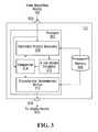
- FIG. 3is a block diagram of a processing module for assessing a characteristic of a product suitable for use in the system depicted in FIG. 1 in accordance with a specific example of implementation of the invention
- FIGS. 4A , 4 B, 4 C, 4 D and 4 Eare flow diagrams of a process implemented by the system depicted in FIG. 1 in accordance with a specific example of implementation of the invention
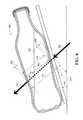
- FIG. 5is a top perspective view of a tray for positioning a bottle in an inclined position during X-ray inspection according to a non-limiting example of implementation of the invention
- FIG. 6Ais an X-ray image of three (3) bottles each at least partially filled with liquid in accordance with a specific example of implementation of the invention.
- FIG. 6Bshows visual representations of reconstructed 3-D images of the three (3) bottles depicted in the X-ray image of FIG. 6A in accordance with a specific example of implementation of the invention
- FIG. 7is a block diagram of an X-ray simulator device suitable for use in connection with the processing module depicted in FIG. 3 in accordance with a specific example of implementation of the invention.
- FIG. 8is a cutaway side view of a bottle partially filled with liquid and maintained in an inclined position in accordance with a non-limiting example of implementation of the invention.
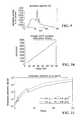
- FIG. 9is a graph depicting a source spectrum of an X-ray tungsten source in an X-ray device in accordance with a non-limiting example of implementation of the invention.
- FIG. 10is a graph depicting a theoretical scintillator response ⁇ low (E);
- FIG. 11is a graph showing attenuation coefficients of Cesium iodide (CsI) and copper (Cu) for different energy levels;
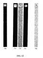
- FIG. 12shows an X-ray image derived by subjecting three (3) slabs of different materials to X-rays
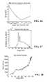
- FIG. 13is a graph showing relative errors between simulated intensities (grey levels) and the observed intensities as a function of an estimated low energy scintillator (detector) thickness, the simulated intensities being generated in accordance with a non-limiting example of implementation of the invention
- FIG. 14is a graph depicting the detected low energy spectrum after optimisation of the low scintillator thickness
- FIG. 15is a graph depicting a spectral response obtained for the low energy scintillator optimized for a determined low scintillator thickness
- FIG. 16is a graph showing relative errors between simulated intensities (grey levels) and the observed intensities as a function of an estimated copper filter thickness, the simulated intensities, being generated in accordance with a non-limiting example of implementation of the invention
- FIG. 17is a graph depicting the detected high spectrum after copper filter thickness optimisation
- FIG. 18is a graph depicting the high spectral response obtained for the high energy scintillator optimized for a determined copper filter thickness
- FIG. 19is a block diagram of a computing apparatus suitable for use in connection with the processing module illustrated in FIG. 3 in accordance with a specific example of implementation of the invention.
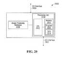
- FIG. 20is a block diagram of a computing apparatus suitable for use in connection with the apparatus illustrated in FIG. 3 in accordance with an alternative specific example of implementation of the invention.
- FIG. 21shows a functional block diagram of a client-server system suitable for assessing a characteristic of a product at a security checkpoint in accordance with an alternative specific example of implementation of the present invention.
- a “bottle holding a liquid”refers to the combination of a body of liquid and the container in which the liquid is contained.
- liquidrefers to a state of matter that is neither gas nor solid, that generally takes the shape of the container in which it is put and has a characteristic readiness to flow. Heterogeneous liquids would also be encompassed by such a definition.
- a “bottle”refers to the container in which the liquid is contained.
- a bottletypically refers to a cylindrical container that is used to contain liquids (namely beverages)
- a bottle in this specificationrefers to any enclosing structure that is made from a material that is suitable to hold the liquid contained within.
- Such containersinclude but are not limited to rigid containers, such as a glass bottle or metal (e.g. Aluminum) containers, as well as semi-rigid containers, such as a bottle made of polyvinyl chloride (PVC), polyethylene or of similar flexible materials.
- the bottlemay be of any shape including generally cylindrical bottles, such as those used for beverages (e.g.
- each bottlehas a transverse dimension and a longitudinal dimension that defines an overall size suitable to be carried in hand-carried luggage that is allowed onboard a commercial aircraft.
- the transverse dimensionis defined by the diameter of the bottle, which may differ between a bottom end and a tapered top end of the bottle.
- bottles containing winetraditionally have a larger circumference at their bottom end that narrows as the bottle tapers at the top end.
- bottles filled with liquid of an overall size suitable for transport in hand-carried luggage allowed onboard a commercial aircraftare those that have a transverse dimension that is less than 5 inches, preferably less than 4 inches, and most preferably less than 3 inches.
- these dimensionsare merely guidelines and may vary depending on the rules and regulations enforced for such articles by local, national and international transportation organizations.
- FIG. 1Shown in FIG. 1 is a screening system 100 suitable for deriving one or more characteristics of a product under inspection at a security checkpoint in accordance with a specific example of implementation of the present invention.
- the present descriptionwill focus on an embodiment of the invention in which the product under inspection is a liquid product comprised of a bottle at least partially filled with liquid and the one or more characteristics derived by the system 100 include a threat status associated with the liquid product.
- the product under inspectionis a liquid product comprised of a bottle at least partially filled with liquid and the one or more characteristics derived by the system 100 include a threat status associated with the liquid product.
- alternative embodiments of the inventionmay be configured to determine other characteristics of liquid products.
- alternative embodiments of the inventionmay be configured to derive material density information, material type information, material chemical formula, one or more linear attenuation coefficients and/or effective atomic number (Z eff number) from an X-ray image associated with the liquid product under inspection.
- Z eff numbereffective atomic number
- alternative embodiments of the inventionmay be configured to detect the presence of solid explosives, drug substances or other non-liquid substances by deriving characteristics of the product under inspection, such as material density information, material type information, material chemical formula, one or more linear attenuation coefficients and/or effective atomic number (Z eff number).
- characteristics of the product under inspectionsuch as material density information, material type information, material chemical formula, one or more linear attenuation coefficients and/or effective atomic number (Z eff number).
- the system 100includes an inspection device 102 for scanning objects, a processing, module 112 for processing data generated by the inspection device 102 and a display device 150 for visually conveying information to a security operator, the information being derived by the processing module 112 and pertaining to the products/objects being scanned by the inspection device 102 .
- the inspection device 102scans a liquid product using penetrating radiation to generate X-ray data conveying an X-ray image of the liquid product.
- the X-ray image dataconveys attenuation information resulting from interaction of X-rays with the liquid product.
- the processing module 112receives the X-ray data from the inspection device 102 and processes that data to derive information related to the threat status of that liquid product.
- the processing, module 112derives characteristics associated with the liquid product under inspection by simulating a response of a reference liquid product to X-rays.
- a purpose of the simulationis to be able to predict output intensity of the X-ray inspection device 102 (shown in FIG. 1 ) at high and low energies based on some level of knowledge (or assumption) of the chemical formula, density and optical path length of the reference product.
- the reference productis associated with known characteristics based on which simulated X-ray image data is generated.
- the simulated X-ray image datais compared with the “real” X-ray image data and the result of the comparison is used to confirm and/or infer the nature of the liquid product under inspection.
- Specific examples of approaches for simulating responses of products to X-rays and for deriving characteristics associated with the liquid product based on simulated responses, including determining the threat status of the liquid product,will be described later on in the specification.
- the processing module 112releases information conveying these characteristics to a security operator.
- the display device 150shown in the figure as a display screen, visually conveys to an operator the determined characteristics of the liquid product, including the threat status of the liquid product, based on the information released by the processing module 112 .
- the system 100can provides assistance to human security personnel in assessing the threat status of a liquid product, including full bottles and partially filled bottles, during security screening.
- the display device 150may be any device suitable for visually conveying information to a user of the system 100 .
- the display device 150may be part of a computing station, as shown in FIG. 1 , may be part of a centralized security station and located remotely from the inspection device 102 or may be integrated into a hand-held portable device (not shown) for example.
- the display device 150includes a printer adapted for displaying in printed format information related to the determined threat status of the liquid product under inspection.
- suitable types of output devicesmay be used.
- the display device 150displays to a user of the system 100 a graphical user interface conveying the determined characteristic(s) of the liquid product, including for example the determined threat status of the liquid product, based on the information released by the processing module 112 .
- the graphical user interfacemay also provide functionality for permitting interaction with a user.
- the information conveying the determined threat status of the liquid productconveys the threat status in terms of a level of threat.
- the level of threatmay be represented as alpha-numeric characters (e.g. SAFE/UNSAFE/UNKNOWN), a color indicator (e.g. RED for unsafe; GREEN for safe and YELLOW for UNKNOWN) and/or using any other suitable manner of conveying a level of threat.
- the information conveying the determined threat status of the liquid productprovides information as to the nature of the liquid product being screened.
- the GUImay indicate that the liquid product may be water, orange juice, hydrogen peroxide and so on.
- a level of confidence in the determinationmay be displayed.
- the GUImay indicate that the liquid product is likely to be water with a level of confidence of 80%.
- the inspection device 102is in the form of an X-ray machine typical of the type of device used to scan luggage at security checkpoints within airports and other locations.
- the X-ray machinemay be a single view X-ray machine or a multi-view X-ray machine.
- the present descriptionwill primarily focus on implementations in which the X-ray machine is of a single-view type. Variants of the invention taking advantage of the multiple X-ray images generated by multi-view X-ray machines will also be presented.
- the inspection device 102includes a scanning area 104 , a conveyor belt 106 , an X-ray source 108 and an array of X-ray detectors 110 .
- the inspection device 102performs an X-ray inspection on a liquid product using penetrating radiation in the form of X-rays to generate X-ray image data associated with the liquid product.
- the scanning area 104(also referred to as a scanning tunnel) is defined by an enclosed void between the X-ray source 108 and the array of X-ray detectors 110 , in which the objects to be scanned are subjected to penetrating radiation, such as X-rays.
- the scanning area 104is typically horizontally oriented and is dimensioned both vertically and horizontally to accommodate the types of objects to be scanned, including articles of hand-carried luggage allowed onboard a commercial aircraft, such as handbags, backpacks, briefcases and shopping bags, among others.
- the scanning area 104is centrally traversed by a conveyor belt 106 that is used to convey objects to be scanned both into and out of the scanning area 104 and is described below.
- the objects to be scannedcan be placed either directly on the conveyor belt 106 or in one or more trays that are then placed on the conveyor belt 106 .
- the conveyor belt 106is a horizontally-oriented continuous belt of material arranged in an endless loop between two terminal rollers.
- the belt 106has an exterior surface on which objects or trays containing the objects to be scanned are placed, as well as an interior surface within which the terminal rollers (as well as other guide rollers and/or supports) lie.
- the width of the conveyor belt 106is sufficient to accommodate the placement of trays within which the objects to be scanned are placed, while its overall length is sufficient to create an endless loop whose length includes:
- terminal rollers constituting the end points of the conveyor belt 106 at the pre-scanning and post-scanning areasmay be connected to motors (not shown) that allow an operator to move the belt 106 forwards or backwards to displace the objects to be scanned between different areas of the X-ray inspection device 102 .
- the X-ray source 108is the source of penetrating radiation (in this case, X-ray radiation).
- the X-ray source 108is located opposite to the array of X-ray detectors 110 so that X-rays emitted by the source 108 pass through the objects that are located on the conveyor belt 106 and are detected by the array of X-ray detectors 110 as a result.
- the inspection device 102is a dual-energy X-ray scanner and the X-ray source 108 emits X-rays at two distinct photon energy levels, either simultaneously or in sequence.
- Example energy levelsinclude 50 keV (50 thousand electron-volts) and 150 keV, although persons skilled in the art will appreciate that other energy levels are possible.
- the array of X-ray detectors 110detects the penetrating radiation (such as X-rays) that was emitted by the X-ray source 108 and that penetrated the objects to be scanned.
- the array of X-ray detectors 110is located opposite to the X-ray source 108 so that X-rays that are emitted by the source 108 pass through the objects that are located on the conveyor belt 106 and are detected by the array 110 .
- liquid products that are to be inspectedare positioned at a known angle (e.g. by means of a tray having an inclined bottom surface) while being scanned by the inspection device 102 .
- a known anglee.g. by means of a tray having an inclined bottom surface
- the meniscuswill tend to migrate toward one of the extremities of the bottle.
- the liquid productsare inclined at a 15° angle from the horizontal plane. It can be appreciated that, in other specific examples of implementation, the angle of incline relative to the horizontal plane can be in the range from about 5° to about 30° and preferably in the range from about 10° to about 20°.
- the angle of inclineis in the range from about 10° to about 15°. This may be achieved through the use of a tray having an included bottom surface, of the type depicted in FIG. 5 , for example.
- a tray having an included bottom surfaceof the type depicted in FIG. 5 , for example.
- PCT International Patent Application serial number PCT/CA2008/002025filed in the Canadian Receiving Office on Nov. 17, 2008 by Michel Roux et al. and presently pending. The contents of the aforementioned documents are incorporated herein by reference.
- liquid products under inspectionmay be positioned in any orientation and any angle, including being positioned in a substantially horizontal plane, while being scanned by the inspection device 102 .
- the liquid products under inspectionmay be positioned within a piece of luggage while being scanned by the inspection device 102 .
- the processing module 112is in communication with the inspection device 102 and receives the X-ray image data output by the array of X-ray detectors 110 .
- the processing module 112is shown as a component external to the inspection device 102 . It will be appreciated that, in alternate example of implementation of the system 100 , the functionality of processing module 112 may be integrated within the inspection device 102 .
- the processing module 112uses the X-ray image data output generated by the array of X-ray detectors 110 of the inspection device 102 to generate an X-ray image of the contents being scanned.
- the X-ray image datacan be processed and/or analyzed further using automated means, as will be shown below.
- FIG. 3 of the drawingsA specific example of implementation of the processing module 112 is depicted in FIG. 3 of the drawings.
- the processing module 112includes an input 300 in communication with the inspection device 102 for receiving there from X-ray image data, a processor 302 in communication with the input 300 , a memory 306 storing data for use by the processor 302 and an output 304 in communication with the display device 150 (shown in FIG. 1 ) for releasing information derived by the processor 302 .
- the memory 306may include different types of information depending on the specific functionality implemented by the processing module 112 .
- the memory 306stores a knowledge database including a plurality of entries associated with respective liquid substances or respective types of liquid substances. Each entry may include, for example, characteristics associated with the respective liquid substance (or type of liquid substance) such as for example, an identification of the liquid substance, a threat status, material density information, material/substance type information, material chemical formula, one or more linear attenuation coefficients and/or an effective atomic number (Z eff number).
- the one or more linear attenuation coefficientsincludes X-ray attenuation coefficients associated to respective portions of the X-ray spectrum.
- the one or more linear attenuation coefficientsmay also include an average low energy linear attenuation coefficient and an average high energy linear attenuation coefficient.
- a tolerance levelmay be associated with one or more of the characteristics of the liquid substance.
- the material density information associated with the liquid substancemay be expressed as a range of densities such as density ⁇ density and the effective atomic number may be expressed as a range of effective atomic numbers Zeff ⁇ Zeff.
- the processor 302implements a process for determining one or more characteristics of a liquid product based on the X-ray data received at input 300 from the inspection device 102 .
- the one or more characteristicsinclude a threat status.
- Results obtained by the processor 302are then released at output 304 .
- the processor 302simulates responses of reference liquid products to X-rays to derive simulated X-ray image data. The simulated X-ray image data is then used to determine one or more characteristics of the liquid product under inspection, including for example the threat status of the liquid product under inspection.
- the processor 302includes a number of sub-components namely a reference product generator module 308 , an x-ray device simulator 310 , an X-ray data comparator device 314 and a characteristic determination module 312 .
- the reference product generator module 308receives X-ray image data from the inspection device 102 (shown in FIG. 1 ), referred to as the “real” X-ray image data, which is associated with the liquid product under inspection, also referred to as the “real” product.
- the reference product generator module 308processes the real X-ray image data to derive geometric information associated with the liquid product under inspection.
- the geometric informationis then used to derive characterization data for a reference product.
- the characterization data of the reference productmay convey, amongst others, shape information associated with the reference product, liquid substance content (or liquid substance type) and positioning information for positioning the reference product relative to a source of X-rays and X-ray detectors.
- the reference product generator module 308receives information from the X-ray data comparator device 314 .
- the reference product generator module 308makes use of the result of a comparison between the X-ray image data from the inspection device 102 and simulated X-ray image data generated by the X-ray device simulator 310 to derive a new reference product having new characterization data.
- the X-ray device simulator 310processes characterization data associated with the reference product (generated by the reference product generator module 308 ) to generate simulated X-ray data by modelling interactions between X-rays and the reference product.
- the X-ray device simulator 310releases the simulated X-ray image data to the X-ray data comparator device 314 .
- a specific example of implementation of the X-ray device simulator 310will be described later on in the specification.
- the X-ray data comparator device 314receives the simulated X-ray image data generated by the X-ray device simulator 310 and compares it to the “real” X-ray image data received at input 300 .
- the simulated X-ray image data and the “real” X-ray image dataeach convey attenuation information in the form of a two-dimensional X-ray image.
- the comparator device 314generates an error map conveying differences in attenuation between the “real” X-ray image data and the simulated X-ray image data.
- the magnitude as well as the distribution of the differences in attenuation between the “real” X-ray image data and the simulated X-ray image dataprovides an indication as to how closely the characterization data of the reference liquid product approximates that of the liquid product under inspection.
- the results of the comparison performed by the X-ray data comparator device 314are provided to the characteristic determination module 312 so that they may be used to confirm and/or infer characteristics of the liquid product under inspection.
- the results of the comparison performed by the X-ray data comparator device 314are provided to the reference product generator module 308 so that they may be used to derive new characterization data associated with a new reference product, where the new reference product is an improved representation of the liquid product under inspection.
- the results of the comparisonare provided to the characteristic determination module 312 along with an indication that the reference product is a poor representation of the liquid product under inspection.
- the characteristic determination module 312is in communication with the X-ray data comparator device 314 and the memory 306 .
- the characteristic determination module 312receives the results of the comparison performed by the X-ray data comparator device 314 and derives one or more characteristics associated with the liquid product under inspection.
- the characteristic determination module 312infers the characteristics of the liquid product under inspection from the characterization data of the reference product.
- the characterization data of the reference productmay convey, amongst others, an estimated liquid substance or liquid substance type held by reference liquid product.
- the estimated liquid substance or liquid substance typecorresponds to an entry in the memory 306 , which stores characteristics associated with the liquid substance or liquid substance type such as, but not limited to an identification of the liquid substance, a threat status, density information, chemical formula, material type information, one or more linear attenuation coefficients and/or an effective atomic number (Z eff number).
- the characteristic determination module 312infers the threat status of the liquid product under inspection from the threat status associated with the estimated liquid substance or liquid substance type of the reference product.
- the characteristic determination module 312can be used to rule out certain characteristics of the liquid product under inspection.
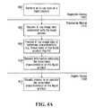
- FIG. 4AA specific example of a process implemented by the system 100 (shown in FIG. 1 ) will now be described with reference to FIG. 4A .
- an X-ray scan of a liquid product to be screenedis performed by the inspection device 102 (shown in FIG. 1 ) to obtain X-ray image data associated with the liquid product.
- the X-ray image dataconveys attenuation information resulting from interaction of X-rays with the liquid product.
- the liquid productis placed directly on the conveyor belt 106 of the inspection device 102 or is placed on a tray, which is then placed on the conveyor belt 106 of the inspection device 102 .
- the liquid productis placed on a tray having an inclined bottom surface and including retaining member for preventing the liquid product from being displaced during inspection.
- a tray of the type depicted in FIG. 5may be used for that purpose.
- the bottom surface of the tray's longitudinal axisforms an angle to the horizontal plane in the range from about 5° to about 40°, preferably in the range from about 5° to about 30°, and more preferably in the range from about 10° to about 20°. In a specific non-limiting practical implementation, the angle is between about 10° and about 15°.
- FIG. 6Ais an X-ray image of three (3) bottles each at least partially filled with liquid derived from data generated by an inspection device in accordance with a specific example of implementation of the invention. In this figure, the meniscus for each bottle has been emphasized for the purpose of illustration only.
- the X-ray image data generated by the inspection device 102is received by the processing module 112 (shown in FIGS. 1 and 3 ).
- the processing module 112processes the X-ray image data to determine one or more characteristics, such as the threat status, of the liquid product scanned at step 400 .
- characteristicssuch as the threat status
- responses of reference liquid products to X-raysare simulated in order to generate simulated X-ray image data.
- the simulated X-ray image datais then used to confirm and/or infer the characteristics of the liquid product under inspection. Specific examples of the manner in which step 404 may be implemented will be described in greater detail below.
- the processing module 112releases information conveying the one or more characteristics determined at step 404 , including for example the threat status, of the liquid product under inspection.
- the display device 150receives the information released by the processing modules and conveys this information in visual format, and optionally in audio format, to an operator.
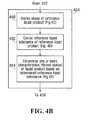
- FIGS. 4B , 4 C, 4 D and 4 EA specific approach for determining at step 404 one or more characteristics of the liquid product under inspection will now be described with reference to FIGS. 4B , 4 C, 4 D and 4 E. It is to be appreciated that the following example has been provided for the purpose of illustration and that many variations are possible and will become apparent to the person skilled in the art in light of the present application.
- steps 490 , 492 and 494 in FIG. 4Bare implemented by the various components 308 , 310 , 314 and 312 of the processor 302 depicted in FIG. 3 .
- shape information associated with a reference liquid productis derived.
- the shape information associated with the reference liquid productis derived at least in part based on the X-ray image data associated with the liquid product under inspection (received at step 402 shown in FIG. 4A ).
- the shape information associated with the reference liquid product derived at step 490is a mathematical representation including information conveying:
- a reference liquid substanceis derived.
- the reference liquid substance derived at step 492potentially corresponds to the liquid substance held by the liquid product under inspection.
- step 492also generates a confidence level indicating how likely it is that the reference liquid substance corresponds to the liquid substance held by the liquid product under inspection.
- one or more characteristics of the liquid product under inspectionare derived based on the reference liquid substance determined at step 492 and, optionally, the confidence level associated with the reference liquid substance.
- step 494the process then proceeds to step 408 described above with reference to FIG. 4A .
- step 490A specific example of implementation of step 490 will now be described with reference to FIG. 4C .
- the X-ray image data received from the inspection device 102is processed to derive geometric information associated with the bottle of the liquid product under inspection.
- the derived geometric information associated with the bottlemay include one or more of the following elements:
- the inspection device 102(shown in FIG. 1 ) is a “multi-view” type X-ray machine generating multiple two-dimensional image of the liquid product
- the multiple imagesmay be used to obtain additional information as to the size, shape and positioning of the bottle.
- suitable methods for extracting geometric information from an imageare known in the art of computer vision and as such will not be described in further detail here.
- a set of candidate bottle shapesis generated based on the geometric information derived at step 450 .
- the candidate bottle shapesare mathematical representation of the shapes of bottles. The person skilled in the art will appreciate that, although there may be some exceptions, most bottles have shapes exhibiting symmetrical properties. For instance, several bottles exhibit some level of rotational symmetry along their longitudinal axis. In a specific non-limiting example of implementation, generating three-dimensional candidate bottle shapes is effected by:
- the set of candidate bottle shapeshave different cross-sectional shapes including, without being limited to, a generally circular shape, a generally elliptical shape, a generally rectangular shape and a generally square shape.
- the set of candidate bottle shapes generated at steps 452 A-Bare associated with location information positioning the candidate bottle shape with reference to the X-ray source and the X-ray detectors in the inspection device 102 (shown in FIG. 1 ).
- FIG. 6B of the drawingsshows in graphical form three-dimensional mathematical representations 950 , 952 and 954 , which correspond respectively to the bottles 900 , 902 and 904 depicted in the X-ray image shown in FIG. 6A .
- the candidate bottle shapes generated at steps 452 A-Bare processed to generate simulated responses to X-rays.
- each candidate bottle shape generated at steps 452 A-Bis processed to derive one or more virtual models, wherein each virtual model corresponds to a respective reference liquid product.
- virtual modelsare generated:
- the length of the paths followed by X-rays through the body of liquid in the virtual modelmay vary.
- multiple levels of fillmay be considered (e.g. 25% full of liquid, 50% full of liquid, 75% full of liquid, 100% full of liquid).
- the number of levels of fill consideredis not limiting and will depend on the desired degree of precision to be attained.
- different combinations of levels of fill (height of meniscus) and types of bottle materialmay be processed in parallel or sequentially depending on the processing capability of the processing module 112 (shown in FIG. 1 ).
- each set of virtual modelsis associated with a respective candidate bottle shape.
- Each virtual modelcorresponds to a reference liquid product associated with characterization data, including:
- the virtual model corresponding to the reference liquid productmay further include information modeling characteristics of a reference tray corresponding to the “real” tray supporting the “real” liquid product.
- the present descriptionwill not describe in detail the modeling of the tray since manners in which the tray may be modeled will become apparent to the person skilled in the art in light of the present description.
- the purpose of the simulationis to be able to predict output intensity of the X-ray inspection device 102 (shown in FIG. 1 ) at high and low energy based on some level of knowledge (or assumption) of the chemical formula, density and optical path length of a reference material or object.
- the simulationis performed using a computer implemented simulation engine and is a coarse modelling of the operation of the X-ray inspection device 102 (shown in FIG. 1 ).
- the simulationaims to derive the likely X-ray attenuation data that would be obtained when a liquid product having shape information corresponding to that generated at one of the steps 452 A-B, filled with a reference liquid, such as water for example, and having a certain level of fill (and optionally having a bottle made with a certain reference material) is screened by the X-ray inspection device 102 .
- a reference liquidsuch as water for example
- One example of a model that can be usedis one which determines the attenuation to which the X-rays would be subjected, at different locations throughout the reference liquid product on the basis of theoretical equations that map attenuation with path length, liquid characteristics and X-ray characteristics.
- the type of bottle material and the default liquid substance in the bottleprovide information pertaining to chemical formula and/or density of the material(s) through which X-rays would travel between the X-ray source and detectors of the X-ray inspection device 102 (shown in FIG. 1 ). It should be noted that:
- steps 454 A-Bis a plurality of simulated X-ray images where each simulated X-ray image conveys simulated attenuation information in the form of a two-dimensional X-ray image and is associated with a respective reference liquid product having a respective shape and holding a default liquid substance (e.g. water).
- a default liquid substancee.g. water
- the simulated X-ray images obtained at steps 454 A-Bare compared to the X-ray image data associated to the liquid product under inspection, also referred to as the “real” X-ray image data, and which was received by the processing module at step 402 (shown in FIG. 4 a ).
- the purpose of the comparisonis to determine the difference between the two.
- an error distribution mapconveying differences in attenuation between the “real” X-ray image data and the simulated X-ray image data is generated for each reference liquid product. This error distribution map can be generated, for example, by subtracting the “real” X-ray image data and the simulated X-ray image data on a pixel by pixel basis.
- the error distribution mapsconvey information pertaining to the magnitude, as well as the distribution of the differences in attenuation between the “real” X-ray image data and the simulated X-ray image data.
- Each error distribution mapprovides an indication as to how closely the characterization data of a corresponding reference liquid product approximates that of the liquid product under inspection.
- the attenuation information generated by the reference liquid productwill likely be different from the attenuation information in the “real” X-ray image data since the liquid substances are likely different.
- the reference liquid productuses a default liquid substance (such as water), while the liquid product under inspection is most likely filled with another liquid substance.
- the candidate shape of the bottle and currently estimated level of fillare generally correct, the attenuation error distribution will be generally uniform.
- the currently estimated level of fill and/or candidate shape of the bottleis far from those of the liquid product under inspection, then the error distribution will not be uniform.
- each error distribution mapprovides an indication as to how closely the characterization data of an associated reference liquid product approximates that of the liquid product under inspection.
- the error distribution mapsare processed to identify a distribution map in which the magnitude and the variations of the differences in attenuation between the “real” X-ray image data and the simulated X-ray image data are smaller than the other error distribution maps.
- the reference liquid product associated with the identified error distribution mapis then selected.
- step 458is characterization data conveying shape information associated with a reference liquid product, where the shape information approximates the shape of the liquid product under inspection.
- step 492a reference liquid substance is derived.
- step 492A specific example of implementation of step 492 will now be described with reference to FIG. 4D .
- the shape information associated with the reference liquid product derived at step 490is processed to generate a set of simulated X-ray responses, where each simulated response to X-rays is associated with a different liquid substance. More specifically, at steps 460 A-B a set of reference liquid products is generated, where each reference liquid product is associated with characterization data including:
- the set of liquid substancesmay include any number of liquid substances and types of substances.
- the set of liquid substancesincludes one or more liquid substances constituting “threat” and one or more liquid substances deemed to be “safe”.
- a response to X-raysis simulated to generate simulated X-ray image data.
- the candidate shape information derived at step 490is used to obtain optical path length information through the body of liquid of the reference liquid product.
- the liquid substance for each reference productprovides information pertaining to chemical formula and or density of the material(s) through which X-rays would travel between the X-ray source and detectors of the X-ray inspection device 102 (shown in FIG. 1 ).
- steps 460 A-Bis a plurality of simulated X-ray images where each simulated X-ray image conveys simulated attenuation information in the form of a two-dimensional X-ray image and is associated with a respective reference liquid product holding a respective liquid substance and characterized with the same shape information derived at step 490 .
- the simulated X-ray images obtained at steps 460 A-Bare compared to the X-ray image data associated to the liquid product under inspection, also referred to as the “real” X-ray image data, and which was received by the processing module 112 at step 402 (shown in FIG. 4A ).
- an error distribution mapconveying differences in attenuation between the “real” X-ray image data and the simulated X-ray image data is generated for each reference liquid product.
- the results of the comparisons performed at steps 462 A-Bare processed to select a virtual model from the sets of candidate virtual models, wherein the selected virtual model corresponds to a reference liquid product.
- the error distribution mapsare processed to identify a distribution map in which the magnitude as well as the variations of the differences in attenuation between the “real” X-ray image data and the simulated X-ray image data are smaller than the other error distribution maps.
- the reference liquid product associated with the identified error distribution mapis then selected.
- step 464is characterization data conveying shape and liquid content information associated with a reference liquid product, where the shape information and the liquid content information approximates the shape and liquid content of the liquid product under inspection.
- step 464also generates a confidence level indicating how likely it is that the reference liquid substance corresponds to the liquid substance held by the liquid product under inspection.
- the confidence levelis derived at least in part based on the error distribution map associated with the selected reference product and may be derived using any suitable manner.
- step 494one or more characteristics of the liquid product under inspection are derived based on the reference liquid substance determined at step 492 .
- step 494A specific example of implementation of step 494 will now be described with reference to FIG. 4E .
- the reference liquid substance and the level of confidenceare received, where the level of confidence indicates how likely it is that the reference liquid substance corresponds to the liquid substance held by the liquid product under inspection.
- the level of confidence received at step 650is compared against a first threshold level of confidence. If the level of confidence exceeds the first threshold, thereby indicating that the reference liquid substance is likely to correspond to the liquid substance held by the liquid product under inspection, the process proceeds to step 654 . If the level of confidence does not exceed the first threshold, the process proceeds to step 662 .
- the characteristics of the liquid product under inspectioncan be inferred from the characteristics of the reference liquid substance.
- the reference liquid substance obtained at step 492is associated to characteristics such as, but not limited to, a threat status, material density, material type, material chemical formula, one or more linear attenuation coefficients and/or an effective atomic number (Z eff number).
- Z eff numbereffective atomic number
- the characteristics of the liquid product under inspectionmay be determined by a simple look-up procedure by using the reference liquid substance determined at step 492 to access a corresponding entry in the memory 306 . The process then proceeds to step 656 , which is described below.
- step 662which is initiated when the level of confidence received at step 650 does not exceed a first threshold level of confidence, the level of confidence received at step 650 is compared against a second threshold level of confidence that is the same or lower than the first level of confidence. If the level of confidence is lower that the second threshold, thereby indicating that the reference liquid substance is unlikely to correspond to the liquid substance held by the liquid product under inspection, the process proceeds to step 660 . If the level of confidence is at least as high as the second threshold, the process proceeds to step 664 .
- step 660which is initiated when the reference liquid substance is unlikely to correspond to the liquid substance held by the liquid product under inspection, a negative determination of the liquid product under inspection is made. For example if the reference liquid substance is water and is associated with a low likelihood of corresponding to the liquid held by the liquid product under inspection, step 660 determines that the liquid held by the liquid product is unlikely to be water. The process then proceeds to step 658 .
- a threat statusis assigned to the liquid product under inspection based in part on the negative determination made at step 660 . For example, if the reference liquid substance is associated with a “safe” threat status from a set of “safe” substances and it is determined at step 660 that the liquid held by the liquid product is unlikely to correspond to this reference liquid substance, then at step 658 a “prohibited” (or equivalent) threat status may be assigned to the liquid product under inspection irrespective of whether the content or not the liquid held by the liquid product constitutes a threat. The reverse type of logic may also be contemplated.
- the reference liquid substanceis a “prohibited” liquid substance from a set of “prohibited” substances, and it is determined at step 660 that the liquid held by the liquid product is unlikely to be the “prohibited” substance, then at step 658 a “safe” (or equivalent) threat status may be assigned to the liquid product under inspection irrespective of whether the content or not the liquid held by the liquid product constitutes a threat. It is to be appreciated that this latter type of logic leaves open the possibility that if the liquid product under inspection holds a dangerous liquid substance that is not in the set of set of “prohibited” substances contemplated by the system, the process shown in figure will erroneously assign a “safe” (or equivalent) threat status to the liquid product. Therefore, practical implementations of this process would preferably take this consideration into account when assigning a threat status at step 658 .
- step 658Once a threat status has been assigned to the liquid product under inspection at step 658 , the process proceeds to step 656 described below.
- step 664which is initiated when the level of confidence received at step 650 is between the first and the second threshold level of confidence, the liquid product under inspection is labelled as being unknown.
- the processwas neither able to provide a sufficiently high level of confidence that the reference liquid substance either corresponded to the liquid product under inspection or a sufficiently low level to rule out the possibility that it may correspond to that reference liquid substance.
- the processthen proceeds to step 668 .
- a threat statusis assigned to the liquid product under inspection based in part on the “unknown” label assigned at step 664 .
- any suitable rulemay be used to assign a threat status.
- all liquid products labelled as “unknown”are assigned a “prohibited” (or equivalent) threat status.
- step 656the characteristics of the liquid product under inspection determined at one of steps 654 , 658 and 668 , are released and the process proceeds to step 408 described above with reference to FIG. 4A .
- the processing module 112includes an X-ray simulator device 310 (shown in FIG. 3 ) which implements a process for simulating responses of reference products to X-rays.
- the purpose of the simulationis to be able to predict output intensity of the X-ray inspection device 102 (shown in FIG. 1 ) at high and low energy based on some level of knowledge (or assumption) of the chemical formula, density and optical path length of a reference material or product that would be positioned in the X-ray path.
- FIG. 3A specific example of implementation of the X-ray simulator device 310 (shown in FIG. 3 ) will be described below with reference to FIG. 7 of the drawings. It is to be appreciated that this description is being presented for the purpose of illustration only and that many other suitable devices for simulating X-ray responses may be contemplated in the art in light of the present description.
- the X-ray simulator device 310includes an input 702 for receiving characterization data associated with a reference product, a processor 700 for processing the characterization data and generate simulated X-ray image data and an output 704 for releasing the simulated X-ray image data generated by the processor 700 .
- the X-ray simulator device 310also includes a memory module 706 storing a plurality of parameters related to the inspection device (such as for example, the inspection device 102 shown in FIG. 1 ) whose behaviour the X-ray simulator 310 is configured to simulate.
- the input 702receives characterization data associated with a reference product from the reference product generator 308 (shown in FIG. 3 ).
- the characterization data receivedprovides information pertaining to material properties and physical dimensions of the reference product from which optical path length and material properties (linear attenuation coefficient, effective atomic number (Z eff ), material density, and/or chemical formula) can be derived.
- the characterization datamay include, for example:
- the processor 700is configured to process the characterization data received at input 702 to generate simulated X-ray image data associated with the reference product by modelling interactions between X-rays and the reference product.
- the processor 700determines the degrees to which an X-ray is attenuated between an X-ray source and a detector as it passes through the reference product.
- the degree to which an X-ray is attenuated between an X-ray source and a detectoris a function of the properties of the substances/materials it passes through, as well as the lengths of the paths travelled by the X-ray through each one of the substances/materials.
- the processor 700processes the characterization data received at input 702 to derive optical path length and material properties (linear attenuation coefficient, effective atomic number (Z eff ), material density, and/or chemical formula) of the paths taken by X-rays between the source of X-rays and detectors. Based on this derived information, the processor 700 determines the attenuation to which the X-rays would be subjected, at different locations throughout the reference liquid product on the basis of theoretical equations that map attenuation with path length, liquid characteristics and X-ray characteristics.
- optical path length and material propertieslinear attenuation coefficient, effective atomic number (Z eff ), material density, and/or chemical formula
- FIG. 8illustrated in graphical form a side cutaway view of a reference liquid product 800 that may be conveyed by characterization data.
- the reference liquid product 800is generally inclined at an angle 801 relative to a generally horizontal plane and is supported by a tray which is also modelled by characterization data.
- FIG. 8also shows a path taken by a ray of penetrating radiation (i.e. an X-ray) through the reference liquid product 800 .
- the X-rayenters the reference liquid product 800 at location 802 , travels through the bottle walls and the bottle contents, and emerges from the bottle at location 814 .
- the angle between the X-ray and the longitudinal axis of the bottle of liquidcan be derived using simple trigonometry since the angle 801 is known and the orientation of the X-ray is also known.
- Segment 810 between the locations 802 and 814is a combination of the following segments:
- the position of the meniscus 820is such that the length of the path segment 812 , which is the length of the path through the inside portion of the bottle 800 , includes a first component 892 corresponding to the length of the path taken by the X-ray passing through the liquid within the bottle but also includes a second component 890 corresponding to the length of a path taken by the X-ray in a layer of air above the meniscus.
- the processor 700 shown in FIG. 7would make use of the characterization data to derive the path length associated with:
- the processor 700 shown in FIG. 7would make use of the characterization data received at the input 702 to derive material properties (linear attenuation coefficient, effective atomic number (Z eff ), material density, and/or chemical formula) for each of the above noted paths and would determine the attenuation to which the X-rays would be subjected on the basis of theoretical equations that map attenuation with path length, liquid characteristics and X-ray characteristics.
- material propertieslinear attenuation coefficient, effective atomic number (Z eff ), material density, and/or chemical formula
- the X-ray characteristics and the attenuation to which the X-rays are subjectedwill vary from one X-ray machine model to another and may even vary between different X-ray machines of a same model.
- calibration informationmust be obtained for that particular X-ray machine model unit. Obtaining this calibration information begins with an estimate of the X-ray source spectrum of the X-ray machine model unit and an estimated scintillator (detector) spectral response for different types of materials.
- additional calibration informationmay be obtained by using tools in the form of material references at regular intervals during the use of the X-ray machine.
- material referencesmay be positioned so as to be scanned by the X-ray beam concurrently with the scanning of a product under inspection and/or periodically in between X-ray scans.
- the simulation process implemented by the X-ray simulator device 310predicts X-ray inspection machine output intensity at high and low energies when an object having a given chemical formula (effective atomic number), density and optical path length is positioned between the source of the X-ray and the detector.
- the non-limiting example of implementation described belowsimulates the polychromatic behaviour of a pseudo dual-energy polychromatic X-ray source and corresponding polychromatic X-ray detectors. It is to be appreciated that other approaches may be used without detracting from the spirit of the invention.
- alternative examples of implementationmay approximate the source of X-rays as being monochromatic and may rely on the average of the detected high spectrum and detected low spectrum for the response of the X-ray detectors. Since real physical X-ray sources have generally polychromatic distributions, it is to be appreciated that results obtained using a monochromatic approximation of the X-ray source may be less precise than those relying on a polychromatic approximation.
- ⁇ c ⁇ ⁇ ( Z eff , E )⁇ i ⁇ ( ⁇ ⁇ ⁇ ( Z i , E ) ) i ⁇ w i Equation ⁇ ⁇ #1
- the above parametersare derived using transmission measurements of plural materials of different effective atomic numbers (Z eff ), density and thickness and primary estimation of source spectrum and scintillator spectral response coupled with a non-linear optimization algorithm.
- FIG. 9is a graph depicting the source spectrum S in (E) for an X-ray tungsten source, which is a common X-ray source used in X-ray devices.
- the spectral distribution of X-ray tungsten sourcesis well known in the art of X-ray machines.
- FIG. 10is a graph depicting a theoretical scintillator response [ ⁇ low (E) and ⁇ high (E)] for a typical Cesium iodide doped with thallium (CsI(TI)) scintillator as a function of absorbed energy.
- the attenuation of the X-ray spectrumcan then be derived since the attenuation coefficient of the scintillator (CsI) is known from its compound formula and density and the attenuation of the copper filter is also known.
- CsIscintillator
- the attenuation of the X-ray spectrumcan be expressed as follows:
- FIG. 11is a graph showing the attenuation coefficients of Cesium iodide (CsI) and copper (Cu) for different energy levels. From this graph, the person skilled in the art will note the presence of “K-edges” at 33 keV for iodine and at 36 keV for the cesium.
- transmission/attenuation datacan be obtained using known chemical formula and density materials.
- FIG. 12shows an X-ray image derived by subjecting three (3) slabs of different materials to X-rays generated by an X-ray machine whose behaviour is to be modelled. As shown, portions 1200 , 1202 and 1204 correspond to the three (3) slabs of different materials and portions 1206 and 1208 correspond to additional references.
- the X-ray simulator calibration stepsmay include the following:
- Certain portions of the processing module 112may be implemented on a general purpose digital computer 1900 , of the type depicted in FIG. 19 , including a processing unit 1902 and a memory 1904 connected by a communication bus.
- the memory 1904stores data 1908 and program instructions 1906 .
- the processing unit 1902is adapted to process the data 1908 and the program instructions 1906 in order to implement the functions described in the specification and depicted in the drawings.
- the digital computer 1900may also comprise an I/O interface 1910 for receiving or sending data elements to external devices, such as the for example the inspection device 102 and the display device 150 (both shown in FIG. 1 ).
- processing module 112can be implemented on a dedicated hardware platform where electrical/optical components implement the functions described in the specification and depicted in the drawings. Specific implementations may be realized using ICs, ASICs, DSPs, FPGA and/or other suitable hardware platform.
- processing module 112can be implemented as a combination of dedicated hardware and software, of the type depicted in FIG. 20 and generally designated by reference numeral 2000 .
- Such an implementationcomprises a dedicated image processing hardware module 2008 and a general purpose computing unit 2006 including a CPU 2012 and a memory 2014 connected by a communication bus.
- the memory 2014stores data 2018 and program instructions 2016 .
- the CPU 2012is adapted to process the data 2018 and the program instructions 2016 in order to implement the functions described in the specification and depicted in the drawings.
- this specific implementationalso comprise one or more I/O interfaces 2004 , 2002 for receiving or sending data elements to external devices such as, for example, inspection and display devices of the type depicted in FIG. 1 .
- the screening system 100may also be of a distributed nature where the X-ray images are obtained by an inspection device in one location (or more than one location) and then are transmitted over a network to another entity implementing the functionality of the processing module 112 described above. Another unit may then transmit a signal for causing one or more display devices to display information to the user, such as the X-ray image of the objects being scanned.
- the display devicemay be located in the same location where the X-ray images of objects were obtained or in an alternate location. In a non-limiting implementation, the display device may be part of a centralized screening facility.
- FIG. 21illustrates a network-based client-server system 2100 for screening objects in accordance with a specific example of implementation of the invention.
- the client-server system 2100includes a plurality of client systems 2102 , 2104 , 2106 and 2108 , as well as inspection devices 2160 A and 2160 B connected to a server system 2110 through a network 2112 .
- Communication links 2114 between the client systems 2102 , 2104 , 2106 , 2108 , the inspection devices 2160 A, 2160 B and the server system 2110can be metallic conductors, optical fibers or wireless, without departing from the spirit of the invention.
- the network 2112may be any suitable network including, but not limited to, a global public network such as the Internet, a private network and a wireless network.
- the server 2110may be adapted to process information received from the inspection devices 2160 A and 2160 B and issue signals conveying screening results to the client systems 2102 , 2104 , 2106 and 2108 using suitable methods known in the computer-related
- the server system 2110includes a program element 2116 for execution by a CPU (not shown).
- Program element 2116includes functionality to implement the functionality of processing module 112 (shown in FIGS. 1 and 3 ) described above.
- Program element 2116also includes the necessary networking functionality to allow the server system 2110 to communicate with the client systems 2102 , 2104 , 2106 and 2108 , as well as the inspection devices 2160 A and 2160 B over the network 2112 .
- the client systems 2102 , 2104 , 2106 and 2108include display devices responsive to signals received from the server system 2110 for displaying screening results derived by the server system 2110 .
- the inspection device 102is embodied as a multi-view X-ray machine.
- the multi-view X-ray machinegenerates X-ray image data associated with the liquid product conveying a first X-ray image of the liquid product taken by subjecting the liquid product to X-rays in a first orientation and a second X-ray image of the liquid product taken by subjecting the liquid product to X-rays in a second orientation.
- the first and second orientationsare different from one another and will frequently be orthogonal to one another, although such differences in orientation may vary depending on the X-ray machine being used.
- the X-ray image data corresponding to the first X-ray image of the liquid productmay be processed to derive information pertaining to the threat status of the liquid product according to the methods described above.
- the X-ray image data corresponding to the second X-ray image of the liquid productis then processed to validate and/or adjust the information derived based on the first X-ray image of the liquid product.
- the first and second X-ray image of the liquid productmay be used jointly to derive shape information associated to a reference liquid product. For example, deriving shape information associated to a reference liquid product (see FIG. 4B , step 490 for example), an initial estimate of the shape information may be derived based on a first X-ray image of the liquid product. This initial estimate of the shape information may then be validated and/or refined by processing the second X-ray image of the liquid product to derive a second estimate of the shape information associated with the liquid product.
- an advantage of using a multi-view X-ray imaging apparatusis that the additional view provides three-dimensional information that is otherwise unavailable from single two-dimensional view.
- these multiple viewsallow deriving a reference liquid product having characteristics that more closely approximate those of the liquid product under inspection.
- the multi-view X-ray machinemay generate X-ray image data conveying X-ray images of the liquid taken by subjecting the liquid product to X-rays in more than two orientations, thereby generating three, four or more X-ray images.
Landscapes
- Physics & Mathematics (AREA)
- Health & Medical Sciences (AREA)
- General Physics & Mathematics (AREA)
- Life Sciences & Earth Sciences (AREA)
- General Health & Medical Sciences (AREA)
- Pathology (AREA)
- Biochemistry (AREA)
- Analytical Chemistry (AREA)
- Chemical & Material Sciences (AREA)
- Immunology (AREA)
- Engineering & Computer Science (AREA)
- Toxicology (AREA)
- Geometry (AREA)
- Computer Vision & Pattern Recognition (AREA)
- Theoretical Computer Science (AREA)
- High Energy & Nuclear Physics (AREA)
- General Life Sciences & Earth Sciences (AREA)
- Geophysics (AREA)
- Analysing Materials By The Use Of Radiation (AREA)
- Nuclear Medicine, Radiotherapy & Molecular Imaging (AREA)
- Radiology & Medical Imaging (AREA)
Abstract
Description
- U.S. provisional patent application Ser. No. 61/151,242 filed on Feb. 10, 2009 by Luc Perron et al. and presently pending.
- PCT International Patent Application serial number PCT/CA2009/000395, entitled “Method and system for performing X-ray inspection of a liquid product at a security check point”, filed in the Canadian Receiving Office on Mar. 27, 2009 by Optosecurity Inc. et al. and presently pending.
- PCT International Patent Application Ser. No. PCT/CA2009/000401 entitled “Method and apparatus for assessing properties of liquids by using X-rays”, filed in the Canadian Receiving Office on Mar. 27, 2009 by Optosecurity Inc. et al. and presently pending.
- U.S. provisional patent application Ser. No. 61/182,243 filed on May 29, 2009 by Dan Gudmundson et al. and presently pending.
- a) simulating responses to X-rays of the candidate virtual models in the set of candidate virtual models to obtain simulated X-ray data;
- b) effecting a comparison between the simulated X-ray data to the X-ray data associated to the liquid product under inspection;
- c) selecting the at least one virtual model from the set of candidate virtual models as the virtual model of the reference liquid product at least in part based on the comparison between the simulated X-ray data and the X-ray data associated to the liquid product under inspection.
- A pre-scanning area that lies before the
scanning area 104, where the objects to be scanned are placed on thebelt 106; - The
scanning area 104, where the objects being scanned are subjected to penetrating radiation (i.e. X-rays); and - A post-scanning area that lies after the
scanning area 104, where the objects that have been scanned emerge after being subjected to penetrating radiation. It is in that area that a user can pick up his or her objects after the security screening operation is completed.
- A pre-scanning area that lies before the
- PCT International Patent Application serial number PCT/CA2008/002025 filed in the Canadian Receiving Office on Nov. 17, 2008 by Michel Roux et al. and presently pending.
- an approximate three-dimensional shape of the bottle of the liquid product under inspection;
- an approximate indication of the level of the liquid in the bottle of the liquid product under inspection;
- location information of the liquid product under inspection with reference to the X-ray source and the X-ray detectors in the
inspection device 102.
- Approximation of the bottle height;
- Approximation of the bottle width;
- Approximation of the bottle length;
- Approximation of the profile of the bottle;
- Approximation of the position of the bottle in the tray;
- Location and orientation of longitudinal axis of the bottle;
- In an implementation in which the liquid product is positioned on a tray having a bottom surface with a known inclination, the angle made between a longitudinal axis of the bottle and a horizontal plane is used to derive the geometric information associated with the bottle;
- Location information of the liquid product under inspection with reference to the X-ray source and the X-ray detectors in the inspection device102 (shown in
FIG. 1 ).
- using the location and orientation of its longitudinal axis obtained at
step 450; - using the length and width of the bottle obtained at
step 450; - (optionally) using the shape of the profile of the bottle along one side of the longitudinal axis obtained at
step 450; and - extrapolating all other points on the bottle by effecting a rotation of the profile of the bottle around the longitudinal axis using a reference cross-sectional shape obtained at
step 450.
- using the location and orientation of its longitudinal axis obtained at
- a) Models assuming a bottle shape corresponding to the candidate bottle shape derived in one of steps452a-b;
- b) Models assuming different types of bottle materials (e.g. glass, plastic, aluminum);
- c) Models assuming different amounts of liquid in the bottle (different levels of fill); and
- d) Models assuming a default liquid substance (e.g. water).
- bottle shape information derived at one of
steps 452A-B; - positioning information for positioning the reference product relative to a source of X-rays derived at one of
steps 452A-B; - default liquid substance information (in a non-limiting example of implementation, the default liquid substance is taken to be water although any other reference liquid substance could be used);
- (optionally) a type of bottle material;
- a level of fill.
- bottle shape information derived at one of
- the X-ray characteristics of the
inspection device 102 can be modelled; - the liquid characteristics of the default liquid substance (e.g. water) are known;
- the length of the path taken by X-ray through the reference liquid product can be derived based on the virtual model; and
- an estimate of the attenuation information can be derived based on the X-ray characteristics of the
inspection device 102, the liquid characteristics of the default liquid substance and the path length information.
- the X-ray characteristics of the
- the shape information derived at step490 (shown in
FIG. 4B ), including fill level; - a respective liquid substance from a set of liquid substances.
- the shape information derived at step490 (shown in
- bottle shape information;
- positioning information for positioning the reference liquid product relative to a source of X-rays;
- liquid substance information;
- (optionally) type of bottle material;
- a level of fill.
segment 804 through the supporting structure (for example a tray);segments segment 812 through the inside portion of thebottle 800.
segment 804 through the supporting structure;segments segment 892 through the liquid within the bottle;segment 890 through the layer of air above the meniscus.
- 1. X-ray photons discrete source emission: Sin(E) where E is in keV.
- 2. The attenuation of the X-ray spectrum when passing through one or plural materials of known chemical composition
density (ρ) and optical path length (t) where
- is the compound mass attenuation coefficient computed using traceable standard mass attenuation coefficients (NIST) for each energy. Mathematically this can be expressed as follows:
- Where wiis the fraction by weight of the ithatomic constituent and
- are the mass attenuation coefficients at each discrete energy of the spectrum of the ithatomic constituent. Each atomic constituent is available in the given chemical formula of the given material/compound.
- The mass attenuation coefficient is related to the chemical formula of the material. In order to represent this dependency, the mass attenuation coefficient relies on Zeff, where Zeff is computed from the chemical formula of the material using:
- where aiis the fractional element of electrons per gram and Ziis the atomic number of the ithatomic element of the chemical formula of the compound.
- The attenuation of the X-ray spectrum Sout(E), after propagation through the material of optical path length t, can then be expressed as follows:
- 3. The amount of attenuation of the transmitted spectrum absorbed by the low energy scintillator (detector) of a given estimated thickness (tlow) and known mass attenuation coefficient
- and density ρscan be expressed as shown in Equations #3a and #3b below:
- Where Slowis the spectrum when it has been modified when passing through a substance and SDetec
— lowis the spectrum when there is no object in the scene. - 4. Visible photon emission (scintillation) of the low energy scintillator described by the spectral visible photon response [γlow(E)] and integration by the photodiode can then be simulated. The integration of the attenuated low detected spectrum can then be normalized by the integration of itself giving us the simulated normalized grey level [0 1] of the machine:
- Where Slowis the spectrum when it has been modified when passing through a substance and SDetec
- 5. Assuming the X-ray machine being modelled is a dual energy X-ray machine, the transmission of X-rays is simulated through a copper filter medium (or other high Z material) of thickness (tf) that manufacturers use to separate the high part from the low part of the spectrum. Mathematically this can be expressed as follows:
- Where Sfilteredis the high energy spectrum when it has been modified when passing through a substance and SDetec
— filteredis the spectrum when there is no object in the scene. - 6. In a specific example of implementation, an approximation is made that the majority of the filtered spectrum is absorbed by the high energy scintillator so that:
Shigh(E)=Sfiltered(E)
SDetect— high(E)=SDetect— filtered(E)Equation # 6 - 7. Then step 4 above is repeated, but this time for the high energy component of the spectrum.
- Where Sfilteredis the high energy spectrum when it has been modified when passing through a substance and SDetec
tlow→Slow(E)→γlow(E),tf→Shigh(E)→γhigh(E)
- A. Low detector thickness optimization:
- The detected or absorbed spectrum will vary depending of the physical thickness of the scintillator (detector). In order to improve the precision of the simulation data, the value of the thickness of the scintillator used in the above model can be adjusted to better reflect the actual physical thickness of the scintillator (detector). In a specific example of implementation, using the information pertaining to the source spectrum and the approximately linear theoretical scintillator response γlow(E) shown in
FIG. 10 ,steps 1 to 4 above are repeated for different estimated thicknesses of the low energy scintillator (detector). The relative error between M simulated low intensities and M observed low intensities is then computed using X-ray image of the slabs of material shown inFIG. 12 . Following this, a low energy scintillator thickness is selected such that the error between observed low intensities on the slabs and simulated intensities values will be minimized. The estimated scintillator thickness is then used in the computation of SDetect— low(E) (see equation #3b above). - Mathematically, the error may be expressed as follows:
- The detected or absorbed spectrum will vary depending of the physical thickness of the scintillator (detector). In order to improve the precision of the simulation data, the value of the thickness of the scintillator used in the above model can be adjusted to better reflect the actual physical thickness of the scintillator (detector). In a specific example of implementation, using the information pertaining to the source spectrum and the approximately linear theoretical scintillator response γlow(E) shown in
- A. Low detector thickness optimization:
FIG. 13 of the drawings is a graph showing relative errors between the observed intensities and the simulated intensities as a function of an estimated low energy scintillator (detector) thickness based on the theoretical scintillator response γlow(E) depicted inFIG. 10 .FIG. 14 is a graph depicting the detected low energy spectrum after optimisation of the low scintillator thickness.
- B. Now that we have SDetect
— low(E), we can useequation # 4 to modify the linear approximation of γlow(E) using an error minimization algorithm.FIG. 15 is a graph showing a version the theoretical response of the scintillator γlow(E) shown inFIG. 10 optimized for a determined low scintillator thickness.
- C. The above process is repeated for the high energy scintillators (detectors), repeating for different estimated thicknesses of the copper filter (tf).
FIG. 16 of the drawings is a graph showing a relative error between the observed intensities and the simulated intensities as a function of an estimated copper filter thickness.FIG. 17 is a graph depicting the detected high spectrum after copper filter thickness optimisation.FIG. 18 is a graph showing a version the theoretical response of the scintillator γhigh(E) shown inFIG. 10 optimized for a determined copper filter thickness.
Specific Practical Implementation
Claims (53)
Priority Applications (1)
| Application Number | Priority Date | Filing Date | Title |
|---|---|---|---|
| US12/864,988US8831331B2 (en) | 2009-02-10 | 2009-06-09 | Method and system for performing X-ray inspection of a product at a security checkpoint using simulation |
Applications Claiming Priority (10)
| Application Number | Priority Date | Filing Date | Title |
|---|---|---|---|
| US15124209P | 2009-02-10 | 2009-02-10 | |
| PCT/CA2009/000401WO2010028474A1 (en) | 2008-09-15 | 2009-03-27 | Method and apparatus for assessing properties of liquids by using x-rays |
| PCT/CA2009/000395WO2010025539A1 (en) | 2008-09-05 | 2009-03-27 | Method and system for performing x-ray inspection of a liquid product at a security checkpoint |
| WOPCT/CA2009/000401 | 2009-03-27 | ||
| CAPCT/CA2009/000395 | 2009-03-27 | ||
| WOPCT/CA2009/000395 | 2009-03-27 | ||
| CAPCT/CA2009/000401 | 2009-03-27 | ||
| US18224309P | 2009-05-29 | 2009-05-29 | |
| US12/864,988US8831331B2 (en) | 2009-02-10 | 2009-06-09 | Method and system for performing X-ray inspection of a product at a security checkpoint using simulation |
| PCT/CA2009/000811WO2010091493A1 (en) | 2009-02-10 | 2009-06-09 | Method and system for performing x-ray inspection of a product at a security checkpoint using simulation |
Related Parent Applications (1)
| Application Number | Title | Priority Date | Filing Date |
|---|---|---|---|
| PCT/CA2009/000811A-371-Of-InternationalWO2010091493A1 (en) | 2009-02-10 | 2009-06-09 | Method and system for performing x-ray inspection of a product at a security checkpoint using simulation |
Related Child Applications (1)
| Application Number | Title | Priority Date | Filing Date |
|---|---|---|---|
| US14/296,838ContinuationUS20140321729A1 (en) | 2009-02-10 | 2014-06-05 | Method and system for performing x-ray inspection of a product at a security checkpoint using simulation |
Publications (2)
| Publication Number | Publication Date |
|---|---|
| US20110051996A1 US20110051996A1 (en) | 2011-03-03 |
| US8831331B2true US8831331B2 (en) | 2014-09-09 |
Family
ID=42561343
Family Applications (2)
| Application Number | Title | Priority Date | Filing Date |
|---|---|---|---|
| US12/864,988Expired - Fee RelatedUS8831331B2 (en) | 2009-02-10 | 2009-06-09 | Method and system for performing X-ray inspection of a product at a security checkpoint using simulation |
| US14/296,838AbandonedUS20140321729A1 (en) | 2009-02-10 | 2014-06-05 | Method and system for performing x-ray inspection of a product at a security checkpoint using simulation |
Family Applications After (1)
| Application Number | Title | Priority Date | Filing Date |
|---|---|---|---|
| US14/296,838AbandonedUS20140321729A1 (en) | 2009-02-10 | 2014-06-05 | Method and system for performing x-ray inspection of a product at a security checkpoint using simulation |
Country Status (3)
| Country | Link |
|---|---|
| US (2) | US8831331B2 (en) |
| EP (1) | EP2396646B1 (en) |
| WO (1) | WO2010091493A1 (en) |
Cited By (10)
| Publication number | Priority date | Publication date | Assignee | Title |
|---|---|---|---|---|
| US20120229631A1 (en)* | 2011-02-14 | 2012-09-13 | Telesecurity Sciences, Inc. | Vendor and scanner independent common workstation for security |
| US20140175289A1 (en)* | 2012-12-21 | 2014-06-26 | R. John Voorhees | Conveyer Belt with Optically Visible and Machine-Detectable Indicators |
| US9157873B2 (en) | 2009-06-15 | 2015-10-13 | Optosecurity, Inc. | Method and apparatus for assessing the threat status of luggage |
| US9170212B2 (en) | 2008-09-05 | 2015-10-27 | Optosecurity Inc. | Method and system for performing inspection of a liquid product at a security checkpoint |
| US9194975B2 (en) | 2009-07-31 | 2015-11-24 | Optosecurity Inc. | Method and system for identifying a liquid product in luggage or other receptacle |
| US10795049B2 (en) | 2018-01-09 | 2020-10-06 | Voti Inc. | Methods for assigning a threat or safe condition to an object in an image |
| US11885752B2 (en) | 2021-06-30 | 2024-01-30 | Rapiscan Holdings, Inc. | Calibration method and device therefor |
| US11977037B2 (en) | 2018-10-22 | 2024-05-07 | Rapiscan Holdings, Inc. | Insert for screening tray |
| US12019035B2 (en) | 2021-07-16 | 2024-06-25 | Rapiscan Holdings, Inc. | Material detection in x-ray security screening |
| US12181422B2 (en) | 2019-09-16 | 2024-12-31 | Rapiscan Holdings, Inc. | Probabilistic image analysis |
Families Citing this family (53)
| Publication number | Priority date | Publication date | Assignee | Title |
|---|---|---|---|---|
| US7313251B2 (en)* | 1993-11-18 | 2007-12-25 | Digimarc Corporation | Method and system for managing and controlling electronic media |
| US10994358B2 (en) | 2006-12-20 | 2021-05-04 | Lincoln Global, Inc. | System and method for creating or modifying a welding sequence based on non-real world weld data |
| US9937577B2 (en) | 2006-12-20 | 2018-04-10 | Lincoln Global, Inc. | System for a welding sequencer |
| US9104195B2 (en) | 2006-12-20 | 2015-08-11 | Lincoln Global, Inc. | Welding job sequencer |
| US8911237B2 (en) | 2008-08-21 | 2014-12-16 | Lincoln Global, Inc. | Virtual reality pipe welding simulator and setup |
| US8657605B2 (en) | 2009-07-10 | 2014-02-25 | Lincoln Global, Inc. | Virtual testing and inspection of a virtual weldment |
| US8747116B2 (en) | 2008-08-21 | 2014-06-10 | Lincoln Global, Inc. | System and method providing arc welding training in a real-time simulated virtual reality environment using real-time weld puddle feedback |
| US8884177B2 (en) | 2009-11-13 | 2014-11-11 | Lincoln Global, Inc. | Systems, methods, and apparatuses for monitoring weld quality |
| US8834168B2 (en) | 2008-08-21 | 2014-09-16 | Lincoln Global, Inc. | System and method providing combined virtual reality arc welding and three-dimensional (3D) viewing |
| US8851896B2 (en) | 2008-08-21 | 2014-10-07 | Lincoln Global, Inc. | Virtual reality GTAW and pipe welding simulator and setup |
| US9280913B2 (en) | 2009-07-10 | 2016-03-08 | Lincoln Global, Inc. | Systems and methods providing enhanced education and training in a virtual reality environment |
| US9318026B2 (en) | 2008-08-21 | 2016-04-19 | Lincoln Global, Inc. | Systems and methods providing an enhanced user experience in a real-time simulated virtual reality welding environment |
| US9196169B2 (en) | 2008-08-21 | 2015-11-24 | Lincoln Global, Inc. | Importing and analyzing external data using a virtual reality welding system |
| US9330575B2 (en) | 2008-08-21 | 2016-05-03 | Lincoln Global, Inc. | Tablet-based welding simulator |
| US9483959B2 (en) | 2008-08-21 | 2016-11-01 | Lincoln Global, Inc. | Welding simulator |
| US8274013B2 (en) | 2009-03-09 | 2012-09-25 | Lincoln Global, Inc. | System for tracking and analyzing welding activity |
| US9310323B2 (en) | 2009-05-16 | 2016-04-12 | Rapiscan Systems, Inc. | Systems and methods for high-Z threat alarm resolution |
| US9230449B2 (en) | 2009-07-08 | 2016-01-05 | Lincoln Global, Inc. | Welding training system |
| US9773429B2 (en) | 2009-07-08 | 2017-09-26 | Lincoln Global, Inc. | System and method for manual welder training |
| US9221117B2 (en) | 2009-07-08 | 2015-12-29 | Lincoln Global, Inc. | System for characterizing manual welding operations |
| US10748447B2 (en) | 2013-05-24 | 2020-08-18 | Lincoln Global, Inc. | Systems and methods providing a computerized eyewear device to aid in welding |
| US9011154B2 (en) | 2009-07-10 | 2015-04-21 | Lincoln Global, Inc. | Virtual welding system |
| US8569655B2 (en) | 2009-10-13 | 2013-10-29 | Lincoln Global, Inc. | Welding helmet with integral user interface |
| US8569646B2 (en) | 2009-11-13 | 2013-10-29 | Lincoln Global, Inc. | Systems, methods, and apparatuses for monitoring weld quality |
| US9468988B2 (en) | 2009-11-13 | 2016-10-18 | Lincoln Global, Inc. | Systems, methods, and apparatuses for monitoring weld quality |
| US8994549B2 (en)* | 2011-01-28 | 2015-03-31 | Schlumberger Technology Corporation | System and method of facilitating oilfield operations utilizing auditory information |
| US9618632B2 (en)* | 2012-03-22 | 2017-04-11 | Duke University | Linear-response nanocrystal scintillators and methods of using the same |
| US20160093233A1 (en) | 2012-07-06 | 2016-03-31 | Lincoln Global, Inc. | System for characterizing manual welding operations on pipe and other curved structures |
| US9767712B2 (en) | 2012-07-10 | 2017-09-19 | Lincoln Global, Inc. | Virtual reality pipe welding simulator and setup |
| CN104769397B (en)* | 2012-09-30 | 2017-03-08 | 圣戈本陶瓷及塑料股份有限公司 | Photoelectric sensor testing device, radiation detection device including photoelectric sensor, and method of selecting photoelectric sensor for radiation detection device |
| US10930174B2 (en) | 2013-05-24 | 2021-02-23 | Lincoln Global, Inc. | Systems and methods providing a computerized eyewear device to aid in welding |
| US20150072323A1 (en) | 2013-09-11 | 2015-03-12 | Lincoln Global, Inc. | Learning management system for a real-time simulated virtual reality welding training environment |
| EP3058353A4 (en)* | 2013-10-16 | 2017-08-30 | Rapiscan Systems, Inc. | Systems and methods for high-z threat alarm resolution |
| US10083627B2 (en) | 2013-11-05 | 2018-09-25 | Lincoln Global, Inc. | Virtual reality and real welding training system and method |
| US9557427B2 (en) | 2014-01-08 | 2017-01-31 | Rapiscan Systems, Inc. | Thin gap chamber neutron detectors |
| US9836987B2 (en) | 2014-02-14 | 2017-12-05 | Lincoln Global, Inc. | Virtual reality pipe welding simulator and setup |
| GB201407811D0 (en)* | 2014-05-02 | 2014-06-18 | Kromek Ltd | Conveyor for scanning system |
| DE102014208711A1 (en)* | 2014-05-09 | 2015-11-12 | Smiths Heimann Gmbh | Method and device for monitoring the attention of an operator |
| EP3111440A1 (en) | 2014-06-02 | 2017-01-04 | Lincoln Global, Inc. | System and method for manual welder training |
| DE102014225592A1 (en)* | 2014-12-11 | 2016-06-16 | Smiths Heimann Gmbh | Person identification for multi-level person checks |
| GB201504360D0 (en) | 2015-03-16 | 2015-04-29 | Univ Leuven Kath | Automated quality control and selection system |
| US10803574B2 (en)* | 2015-06-30 | 2020-10-13 | Illinois Tool Works Inc. | Inline x-ray measurement apparatus and method |
| EP3319066A1 (en) | 2016-11-04 | 2018-05-09 | Lincoln Global, Inc. | Magnetic frequency selection for electromagnetic position tracking |
| US10878591B2 (en) | 2016-11-07 | 2020-12-29 | Lincoln Global, Inc. | Welding trainer utilizing a head up display to display simulated and real-world objects |
| US10913125B2 (en) | 2016-11-07 | 2021-02-09 | Lincoln Global, Inc. | Welding system providing visual and audio cues to a welding helmet with a display |
| US10997872B2 (en) | 2017-06-01 | 2021-05-04 | Lincoln Global, Inc. | Spring-loaded tip assembly to support simulated shielded metal arc welding |
| GB201805669D0 (en) | 2018-04-05 | 2018-05-23 | Kromek Ltd | Conveyor System |
| US11557223B2 (en) | 2018-04-19 | 2023-01-17 | Lincoln Global, Inc. | Modular and reconfigurable chassis for simulated welding training |
| US11475792B2 (en) | 2018-04-19 | 2022-10-18 | Lincoln Global, Inc. | Welding simulator with dual-user configuration |
| US10890544B1 (en) | 2019-12-18 | 2021-01-12 | Field Service Solutions LLC | Nuclear densitometer assemblies for hydraulic fracturing |
| WO2022006429A2 (en)* | 2020-07-02 | 2022-01-06 | Battelle Memorial Institute | Tray inserts and image quality, systems, methods and algorithm for quantifying tray's impact using the same |
| USD1079007S1 (en)* | 2022-02-14 | 2025-06-10 | Delta Electronics, Inc. | X-ray security machine |
| CN117049109B (en)* | 2023-08-18 | 2025-10-03 | 清华大学 | Control method, device, electronic device, storage medium and transmission system |
Citations (138)
| Publication number | Priority date | Publication date | Assignee | Title |
|---|---|---|---|---|
| US3342397A (en) | 1967-01-30 | 1967-09-19 | Duitsman Kenneth | Divided food service tray |
| US3589511A (en) | 1969-08-13 | 1971-06-29 | Owens Illinois Inc | Package and tray for tubes or the like |
| US3609045A (en) | 1969-10-01 | 1971-09-28 | Kurt Stein | Apparatus for storing and visibly comparing the optical properties of minature samples |
| US3673394A (en) | 1969-02-18 | 1972-06-27 | North American Rockwell | Measuring method and apparatus |
| US4392237A (en) | 1980-08-25 | 1983-07-05 | General Electric Company | Scanning x-ray inspection system |
| US4454949A (en) | 1982-04-16 | 1984-06-19 | Paul Flum Ideas, Inc. | Product merchandising display unit |
| US4497065A (en)* | 1982-07-12 | 1985-01-29 | Westinghouse Electric Corp. | Target recognition system enhanced by active signature measurements |
| US4864142A (en) | 1988-01-11 | 1989-09-05 | Penetron, Inc. | Method and apparatus for the noninvasive interrogation of objects |
| US4870666A (en) | 1986-08-07 | 1989-09-26 | General Electric Company | Computer tomographic phantom |
| US4927022A (en) | 1986-07-28 | 1990-05-22 | Corstor (Proprietary) Limited | Core trays |
| US4962515A (en) | 1989-11-13 | 1990-10-09 | The General Hospital Corporation | Ridged compression assembly for mammography apparatus |
| US4974247A (en) | 1987-11-24 | 1990-11-27 | The Boeing Company | System for radiographically inspecting an object using backscattered radiation and related method |
| US4985906A (en) | 1987-02-17 | 1991-01-15 | Arnold Ben A | Calibration phantom for computer tomography system |
| US5044002A (en) | 1986-07-14 | 1991-08-27 | Hologic, Inc. | Baggage inspection and the like |
| US5056124A (en) | 1989-05-24 | 1991-10-08 | Meiji Milk Products Co., Ltd. | Method of and apparatus for examining objects in containers in non-destructive manner |
| WO1994012855A1 (en) | 1992-11-25 | 1994-06-09 | Arnold Ben A | Apparatus and method of quantifying calcium density |
| US5400381A (en) | 1992-07-20 | 1995-03-21 | Scientific Measurement Systems, Inc. | Process for analyzing the contents of containers |
| US5428657A (en) | 1994-03-22 | 1995-06-27 | Georgia Tech Research Corporation | X-ray monitoring system |
| US5442672A (en) | 1993-03-31 | 1995-08-15 | Bjorkholm; Paul J. | Three-dimensional reconstruction based on a limited number of X-ray projections |
| US5490218A (en) | 1990-08-10 | 1996-02-06 | Vivid Technologies, Inc. | Device and method for inspection of baggage and other objects |
| US5557108A (en) | 1993-10-25 | 1996-09-17 | T+E,Uml U+Ee Mer; T+E,Uml U+Ee May O. | Integrated substance detection and identification system |
| US5568262A (en)* | 1994-05-31 | 1996-10-22 | Lachapelle; Joseph G. | Non-destructive fill volume measurement system |
| US5600303A (en) | 1993-01-15 | 1997-02-04 | Technology International Incorporated | Detection of concealed explosives and contraband |
| US5600700A (en) | 1995-09-25 | 1997-02-04 | Vivid Technologies, Inc. | Detecting explosives or other contraband by employing transmitted and scattered X-rays |
| WO1998002763A1 (en) | 1996-07-12 | 1998-01-22 | American Science And Engineering, Inc. | Side scatter tomography system |
| US5768334A (en) | 1993-05-28 | 1998-06-16 | Europ Scan | Method and device for identifying designated materials in the composition of an object |
| US5864600A (en) | 1995-09-27 | 1999-01-26 | Thermedics Detection Inc. | Container fill level and pressurization inspection using multi-dimensional images |
| WO1999045371A1 (en) | 1998-03-02 | 1999-09-10 | Image Anaylsis, Inc. | Automated x-ray bone densitometer |
| US5974111A (en)* | 1996-09-24 | 1999-10-26 | Vivid Technologies, Inc. | Identifying explosives or other contraband by employing transmitted or scattered X-rays |
| US6018562A (en) | 1995-11-13 | 2000-01-25 | The United States Of America As Represented By The Secretary Of The Army | Apparatus and method for automatic recognition of concealed objects using multiple energy computed tomography |
| US6026171A (en) | 1998-02-11 | 2000-02-15 | Analogic Corporation | Apparatus and method for detection of liquids in computed tomography data |
| US6041132A (en)* | 1997-07-29 | 2000-03-21 | General Electric Company | Computed tomography inspection of composite ply structure |
| US6054712A (en) | 1998-01-23 | 2000-04-25 | Quanta Vision, Inc. | Inspection equipment using small-angle topography in determining an object's internal structure and composition |
| US6069936A (en) | 1997-08-18 | 2000-05-30 | Eg&G Astrophysics | Material discrimination using single-energy x-ray imaging system |
| US6078642A (en)* | 1998-02-11 | 2000-06-20 | Analogice Corporation | Apparatus and method for density discrimination of objects in computed tomography data using multiple density ranges |
| US6175655B1 (en)* | 1996-09-19 | 2001-01-16 | Integrated Medical Systems, Inc. | Medical imaging system for displaying, manipulating and analyzing three-dimensional images |
| US6201850B1 (en) | 1999-01-26 | 2001-03-13 | Agilent Technologies, Inc. | Enhanced thickness calibration and shading correction for automatic X-ray inspection |
| US20010033636A1 (en) | 1999-11-13 | 2001-10-25 | Martin Hartick | Method and apparatus for determining a material of a detected item |
| US20020097833A1 (en) | 2001-01-19 | 2002-07-25 | Bruce Kaiser | Methods for identification and verification |
| US6542574B2 (en) | 1998-12-01 | 2003-04-01 | American Science And Engineering, Inc. | System for inspecting the contents of a container |
| US20030062373A1 (en) | 2001-10-01 | 2003-04-03 | Holland Steven Craig | Security tray |
| WO2003052398A1 (en) | 2001-12-19 | 2003-06-26 | Agresearch Limited | Calibration method and apparatus |
| US6654445B2 (en) | 2001-05-04 | 2003-11-25 | Regents Of The University Of California | Device and method for determining proportions of body materials |
| US20040016271A1 (en) | 2002-07-23 | 2004-01-29 | Kirti Shah | Portable inspection containers |
| US6707381B1 (en) | 2001-06-26 | 2004-03-16 | Key-Trak, Inc. | Object tracking method and system with object identification and verification |
| US6707879B2 (en) | 2001-04-03 | 2004-03-16 | L-3 Communications Security And Detection Systems | Remote baggage screening system, software and method |
| US6721387B1 (en) | 2001-06-13 | 2004-04-13 | Analogic Corporation | Method of and system for reducing metal artifacts in images generated by x-ray scanning devices |
| US20040101097A1 (en) | 2002-11-25 | 2004-05-27 | Kyoichiro Wakayama | Apparatus and method for detecting threats |
| US6753527B1 (en)* | 2000-02-03 | 2004-06-22 | Suntory Limited | Method and device for imaging liquid-filling container |
| US6763083B2 (en) | 2002-08-30 | 2004-07-13 | The United States Of America As Represented By The Administrator Of The National Aeronautics And Space Administration | Article screening system |
| USH2110H1 (en) | 2002-07-30 | 2004-10-05 | The United States Of America As Represented By The Secretary Of The Air Force | Automated security scanning process |
| US20040232092A1 (en) | 2003-05-22 | 2004-11-25 | Cash James M | Storage unit and system |
| US20040252024A1 (en) | 2003-06-11 | 2004-12-16 | Huey John H. | Screening checkpoint for passengers and baggage |
| US6840120B2 (en) | 1998-07-08 | 2005-01-11 | Hitachi, Ltd. | Explosive detection system and sample collecting device |
| US20050036689A1 (en) | 2003-07-22 | 2005-02-17 | L-3 Communications Security And Detection Systems | Methods and apparatus for detecting objects in baggage |
| US20050058242A1 (en) | 2003-09-15 | 2005-03-17 | Peschmann Kristian R. | Methods and systems for the rapid detection of concealed objects |
| US20050078801A1 (en) | 2003-10-14 | 2005-04-14 | Georgeson Gary E. | Computed tomography image quality phantom |
| US20050111618A1 (en) | 2002-12-23 | 2005-05-26 | Sommer Edward J.Jr. | Method and apparatus for improving baggage screening examination |
| US20050117700A1 (en) | 2003-08-08 | 2005-06-02 | Peschmann Kristian R. | Methods and systems for the rapid detection of concealed objects |
| US20050173284A1 (en) | 2002-07-03 | 2005-08-11 | Ambrefe Joseph T.Jr. | Advertising trays for security screening |
| US20050193648A1 (en) | 2004-02-27 | 2005-09-08 | Klein Christian P. | Security screening system |
| US6952163B2 (en) | 2003-06-11 | 2005-10-04 | Quantum Magnetics, Inc. | Combined systems user interface for centralized monitoring of a screening checkpoint for passengers and baggage |
| US20050238232A1 (en)* | 2004-04-26 | 2005-10-27 | Zhengrong Ying | Method and system for detecting threat objects using computed tomography images |
| CA2574402A1 (en) | 2004-07-20 | 2006-01-26 | William Awad | System and method for detecting the presence of a threat in a package |
| US20060054682A1 (en) | 2004-09-07 | 2006-03-16 | Carlos De La Huerga | Method and system for tracking and verifying medication |
| US20060078085A1 (en) | 2002-06-17 | 2006-04-13 | Royal Holloway & Bedford New College A University | Stereoscopic x-ray imaging apparatus for obtaining three dimensional coordinates |
| US7033070B2 (en)* | 2000-06-26 | 2006-04-25 | Nec Corporation | Method and apparatus for measuring temperature |
| US20060086794A1 (en) | 1999-06-07 | 2006-04-27 | Metrologic Instruments, Inc.. | X-radiation scanning system having an automatic object identification and attribute information acquisition and linking mechanism integrated therein |
| GB2420683A (en) | 2004-11-26 | 2006-05-31 | Univ Tsinghua | A CT Method And Apparatus For Identifying A Liquid Article Based On The Density Of The Liquid Article |
| US20060115044A1 (en) | 2004-11-26 | 2006-06-01 | Wanlong Wu | Method and an apparatus for liquid safety-detection with a radiation source |
| US7065175B2 (en) | 2003-03-03 | 2006-06-20 | Varian Medical Systems Technologies, Inc. | X-ray diffraction-based scanning system |
| US20060133566A1 (en) | 2004-11-26 | 2006-06-22 | Tsinghua University | Method and apparatus for liquid safety-detection by backscatter with a radiation source |
| US7092485B2 (en) | 2003-05-27 | 2006-08-15 | Control Screening, Llc | X-ray inspection system for detecting explosives and other contraband |
| JP2006214725A (en) | 2004-07-14 | 2006-08-17 | Hitachi Ltd | X-ray liquid level inspection system |
| US20060187221A1 (en) | 2005-02-22 | 2006-08-24 | Sarang Lakare | System and method for identifying and removing virtual objects for visualization and computer aided detection |
| US20060203960A1 (en) | 2003-02-13 | 2006-09-14 | Koninklijke Philips Electronics N.V. | Method and device for examining an object |
| US20060257005A1 (en) | 2005-05-11 | 2006-11-16 | Optosecurity Inc. | Method and system for screening cargo containers |
| US7149339B2 (en)* | 2003-02-25 | 2006-12-12 | Schlumberger Technology Corporation | Non-destructive inspection of downhole equipment |
| US7154985B2 (en)* | 2003-05-13 | 2006-12-26 | Medical Insight A/S | Method and system for simulating X-ray images |
| US20070003009A1 (en) | 2005-01-10 | 2007-01-04 | Rapiscan Systems | Integrated carry-on baggage cart and passenger screening station |
| US7164750B2 (en) | 2003-03-26 | 2007-01-16 | Smiths Detection, Inc. | Non-destructive inspection of material in container |
| US20070013519A1 (en) | 2004-08-26 | 2007-01-18 | Chung Kevin K | Object monitoring, locating, and tracking system employing RFID devices |
| US20070041612A1 (en) | 2005-05-11 | 2007-02-22 | Luc Perron | Apparatus, method and system for screening receptacles and persons, having image distortion correction functionality |
| US20070041613A1 (en) | 2005-05-11 | 2007-02-22 | Luc Perron | Database of target objects suitable for use in screening receptacles or people and method and apparatus for generating same |
| US20070098142A1 (en) | 2005-10-24 | 2007-05-03 | Peter Rothschild | X-Ray Inspection Based on Scatter Detection |
| CA2623812A1 (en) | 2005-10-25 | 2007-05-03 | The State Of Oregon Acting By And Through The State Board Of Higher Educ Ation On Behalf Of The University Of Oregon | Imaging method and device with dual reading scanner |
| US20070133743A1 (en) | 2005-12-09 | 2007-06-14 | Tait Johnson | Security scanner with bin return device |
| US20070132580A1 (en) | 2002-07-03 | 2007-06-14 | Ambrefe Joseph T Jr | Trays for use in security screening |
| US20070152033A1 (en) | 2003-11-21 | 2007-07-05 | Hind John R | Merchandise-Integral Transaction Receipt and Auditable Product Ownership Trail |
| US7257188B2 (en) | 2004-03-01 | 2007-08-14 | Varian Medical Systems Technologies, Inc. | Dual energy radiation scanning of contents of an object |
| US20070192850A1 (en) | 2004-03-12 | 2007-08-16 | Ingenia Technology Limited | Authenticity verification methods, products and apparatuses |
| US7260254B2 (en)* | 2002-11-25 | 2007-08-21 | Mirada Solutions Limited | Comparing images |
| US20070217571A1 (en) | 2004-08-05 | 2007-09-20 | L-3 Communications Security And Detection Systems, Inc. | Increased throughput inspection station |
| US20070297560A1 (en) | 2006-03-03 | 2007-12-27 | Telesecurity Sciences, Inc. | Method and system for electronic unpacking of baggage and cargo |
| WO2008009134A1 (en) | 2006-07-20 | 2008-01-24 | Optosecurity Inc. | Methods and systems for use in security screening, with parallel processing capability |
| WO2008019473A1 (en) | 2006-08-16 | 2008-02-21 | Optosecurity Inc. | Method and apparatus for use in security screening providing incremental display of threat detection information and security system incorporating same |
| US20080056443A1 (en) | 2006-09-05 | 2008-03-06 | Haifeng Hu | Method and device for security-inspection of liquid articles with radiations |
| GB2441551A (en) | 2006-09-05 | 2008-03-12 | Nuctech Co Ltd | Method and apparatus for security inspection of liquid articles using radiation |
| US20080062262A1 (en) | 2005-05-11 | 2008-03-13 | Luc Perron | Apparatus, method and system for screening receptacles and persons |
| WO2008036456A2 (en) | 2006-09-21 | 2008-03-27 | Helen Of Troy Limited | Cutlery tray |
| CA2666838A1 (en) | 2006-09-18 | 2008-03-27 | Optosecurity Inc. | Method and apparatus for assessing characteristics of liquids |
| US7355402B1 (en)* | 2006-11-20 | 2008-04-08 | Echo Medical Systems, Llc | Method and apparatus for hazardous liquid detection |
| WO2008040119A1 (en) | 2006-10-02 | 2008-04-10 | Optosecurity Inc. | Tray for assessing the threat status of an article at a security check point |
| US20080116267A1 (en) | 2006-11-08 | 2008-05-22 | Barber Jeffrey B | Container screener |
| US20080138475A1 (en) | 2004-11-05 | 2008-06-12 | Heuft Systemtechnik Gmbh | Method of Establishing the Integrity of a Product Located in a Container |
| US20080152082A1 (en) | 2006-08-16 | 2008-06-26 | Michel Bouchard | Method and apparatus for use in security screening providing incremental display of threat detection information and security system incorporating same |
| US20080167552A1 (en)* | 2007-01-04 | 2008-07-10 | General Electric Company | System and method of generating an image of a contrast agent injected into an imaged subject |
| US20080170660A1 (en) | 2006-05-11 | 2008-07-17 | Dan Gudmundson | Method and apparatus for providing threat image projection (tip) in a luggage screening system, and luggage screening system implementing same |
| US20080181473A1 (en)* | 2006-08-25 | 2008-07-31 | Guy Garty | Systems and methods for high-throughput radiation biodosimetry |
| US20080240578A1 (en) | 2007-03-30 | 2008-10-02 | Dan Gudmundson | User interface for use in security screening providing image enhancement capabilities and apparatus for implementing same |
| WO2008119151A1 (en) | 2007-03-30 | 2008-10-09 | Optosecurity Inc. | User interface for use in security screening providing image enhancement capabilities and apparatus for implementing same |
| US20080312768A1 (en) | 2007-06-14 | 2008-12-18 | Kenneth James Ewing | Devices and methods for detecting hazardous materials |
| WO2009024818A1 (en) | 2007-08-17 | 2009-02-26 | Durham Scientific Crystals Limited | Method and apparatus for identification and detection of liquids |
| US20090060135A1 (en) | 2005-12-16 | 2009-03-05 | Edward James Morton | X-Ray Tomography Inspection Systems |
| WO2009043145A1 (en) | 2007-10-01 | 2009-04-09 | Optosecurity Inc. | Method and devices for assessing the threat status of an article at a security check point |
| WO2009046529A1 (en) | 2007-10-10 | 2009-04-16 | Optosecurity Inc. | Method, apparatus and system for use in connection with the inspection of liquid merchandise |
| US20090146061A1 (en) | 2007-12-05 | 2009-06-11 | Alessandro Manneschi | Device for analysing composition of contents of a container |
| US20090168963A1 (en) | 2007-12-28 | 2009-07-02 | Geoffrey Harding | Method, a processor, and a system for identifying a substance |
| WO2009114928A1 (en) | 2008-03-17 | 2009-09-24 | Optosecurity, Inc. | Method and apparatus for assessing characteristics of liquids |
| US20090252295A1 (en) | 2008-04-03 | 2009-10-08 | L-3 Communications Security And Detection Systems, Inc. | Generating a representation of an object of interest |
| WO2009127353A1 (en) | 2008-04-18 | 2009-10-22 | Smiths Heimann | Method and apparatus for detection of a particular material in an object by means of electromagnetic radiation |
| US7614788B2 (en) | 2005-12-09 | 2009-11-10 | Ge Security, Inc. | Apparatus and method for providing a shielding means for an x-ray detection system |
| WO2010025539A1 (en) | 2008-09-05 | 2010-03-11 | Optosecurity Inc. | Method and system for performing x-ray inspection of a liquid product at a security checkpoint |
| WO2010028474A1 (en) | 2008-09-15 | 2010-03-18 | Optosecurity Inc. | Method and apparatus for assessing properties of liquids by using x-rays |
| EP2189785A1 (en) | 2007-10-05 | 2010-05-26 | Tsinghua University | Method and device for detecting liquid article |
| US20100220910A1 (en)* | 2009-03-02 | 2010-09-02 | General Electric Company | Method and system for automated x-ray inspection of objects |
| US7789401B2 (en) | 2002-07-03 | 2010-09-07 | Securitypoint Holdings, Llc. | Carts for use in security screening |
| US7840360B1 (en)* | 2006-10-26 | 2010-11-23 | Micheels Ronald H | Optical system and method for inspection and characterization of liquids in vessels |
| WO2010145016A1 (en) | 2009-06-15 | 2010-12-23 | Optosecurity Inc. | Method and apparatus for assessing the threat status of luggage |
| US7873201B2 (en)* | 2004-11-10 | 2011-01-18 | L-3 Communications Security and Detection Systems Inc. | Reconstruction of x-ray images into basis function components using multiple-energy sources |
| US7945017B2 (en)* | 2007-10-05 | 2011-05-17 | Tsinghua University | Method and device for inspection of liquid articles |
| CA2709468C (en) | 2008-09-05 | 2011-06-14 | Michel Bouchard | Method and system for performing x-ray inspection of a liquid product at a security checkpoint |
| US8090150B2 (en)* | 2008-10-10 | 2012-01-03 | Morpho Detection, Inc. | Method and system for identifying a containment vessel |
| US8150105B2 (en)* | 2008-05-22 | 2012-04-03 | International Electronic Machines Corporation | Inspection using three-dimensional profile information |
| CA2692662C (en) | 2008-09-05 | 2012-06-12 | Optosecurity Inc. | Method and system for performing x-ray inspection of a liquid product at a security checkpoint |
| CA2696031C (en) | 2009-02-10 | 2012-08-21 | Optosecurity Inc. | Method and system for performing x-ray inspection of a product at a security checkpoint using simulation |
| US8260020B2 (en)* | 2007-12-31 | 2012-09-04 | Morpho Detection, Inc. | Image based computed tomography number and volume corrections for thin objects in computed tomography systems |
| US20120275646A1 (en) | 2009-07-31 | 2012-11-01 | Optosecurity Inc. | Method, apparatus and system for determining if a piece of luggage contains a liquid product |
Family Cites Families (9)
| Publication number | Priority date | Publication date | Assignee | Title |
|---|---|---|---|---|
| DE3530955A1 (en)* | 1985-08-29 | 1987-03-05 | Heimann Gmbh | LUGGAGE TEST SYSTEM |
| US5040200A (en)* | 1989-05-08 | 1991-08-13 | Scientific Innovations, Inc. | Gamma-gamma resonance in activation analysis, and particularly, its application to detection of nitrogen based explosives in luggage |
| US5022062A (en)* | 1989-09-13 | 1991-06-04 | American Science And Engineering, Inc. | Automatic threat detection based on illumination by penetrating radiant energy using histogram processing |
| US5251240A (en)* | 1990-05-04 | 1993-10-05 | Massachusetts Institute Of Technology | Method and apparatus for employing resonance-produced gamma rays to detect the presence of both nitrogen and oxygen in objects that may contain explosives |
| US5182764A (en)* | 1991-10-03 | 1993-01-26 | Invision Technologies, Inc. | Automatic concealed object detection system having a pre-scan stage |
| US6061469A (en)* | 1998-06-22 | 2000-05-09 | Mitsubishi Electric Information Technology Center America, Inc (Ita) | Object rendering system to produce X-ray like images |
| US6674835B2 (en)* | 2001-10-12 | 2004-01-06 | General Electric Co. | Methods and apparatus for estimating a material composition of an imaged object |
| US7092484B1 (en)* | 2002-06-14 | 2006-08-15 | Iowa State University Research Foundation, Inc. | Model-assisted reconstruction of volumetric data |
| IL159406A (en)* | 2003-12-16 | 2013-10-31 | Mark Goldberg | Method and system for detecting substances such as special nuclear materials |
- 2009
- 2009-06-09USUS12/864,988patent/US8831331B2/ennot_activeExpired - Fee Related
- 2009-06-09WOPCT/CA2009/000811patent/WO2010091493A1/enactiveApplication Filing
- 2009-06-09EPEP09839849.8Apatent/EP2396646B1/enactiveActive
- 2014
- 2014-06-05USUS14/296,838patent/US20140321729A1/ennot_activeAbandoned
Patent Citations (166)
| Publication number | Priority date | Publication date | Assignee | Title |
|---|---|---|---|---|
| US3342397A (en) | 1967-01-30 | 1967-09-19 | Duitsman Kenneth | Divided food service tray |
| US3673394A (en) | 1969-02-18 | 1972-06-27 | North American Rockwell | Measuring method and apparatus |
| US3589511A (en) | 1969-08-13 | 1971-06-29 | Owens Illinois Inc | Package and tray for tubes or the like |
| US3609045A (en) | 1969-10-01 | 1971-09-28 | Kurt Stein | Apparatus for storing and visibly comparing the optical properties of minature samples |
| US4392237A (en) | 1980-08-25 | 1983-07-05 | General Electric Company | Scanning x-ray inspection system |
| US4454949A (en) | 1982-04-16 | 1984-06-19 | Paul Flum Ideas, Inc. | Product merchandising display unit |
| US4497065A (en)* | 1982-07-12 | 1985-01-29 | Westinghouse Electric Corp. | Target recognition system enhanced by active signature measurements |
| US5044002A (en) | 1986-07-14 | 1991-08-27 | Hologic, Inc. | Baggage inspection and the like |
| US4927022A (en) | 1986-07-28 | 1990-05-22 | Corstor (Proprietary) Limited | Core trays |
| US4870666A (en) | 1986-08-07 | 1989-09-26 | General Electric Company | Computer tomographic phantom |
| US4985906A (en) | 1987-02-17 | 1991-01-15 | Arnold Ben A | Calibration phantom for computer tomography system |
| US4974247A (en) | 1987-11-24 | 1990-11-27 | The Boeing Company | System for radiographically inspecting an object using backscattered radiation and related method |
| US4864142A (en) | 1988-01-11 | 1989-09-05 | Penetron, Inc. | Method and apparatus for the noninvasive interrogation of objects |
| US5056124A (en) | 1989-05-24 | 1991-10-08 | Meiji Milk Products Co., Ltd. | Method of and apparatus for examining objects in containers in non-destructive manner |
| US4962515A (en) | 1989-11-13 | 1990-10-09 | The General Hospital Corporation | Ridged compression assembly for mammography apparatus |
| US5490218A (en) | 1990-08-10 | 1996-02-06 | Vivid Technologies, Inc. | Device and method for inspection of baggage and other objects |
| US5838758A (en) | 1990-08-10 | 1998-11-17 | Vivid Technologies | Device and method for inspection of baggage and other objects |
| US5400381A (en) | 1992-07-20 | 1995-03-21 | Scientific Measurement Systems, Inc. | Process for analyzing the contents of containers |
| WO1994012855A1 (en) | 1992-11-25 | 1994-06-09 | Arnold Ben A | Apparatus and method of quantifying calcium density |
| US5600303A (en) | 1993-01-15 | 1997-02-04 | Technology International Incorporated | Detection of concealed explosives and contraband |
| US5692029A (en) | 1993-01-15 | 1997-11-25 | Technology International Incorporated | Detection of concealed explosives and contraband |
| US5442672A (en) | 1993-03-31 | 1995-08-15 | Bjorkholm; Paul J. | Three-dimensional reconstruction based on a limited number of X-ray projections |
| US5768334A (en) | 1993-05-28 | 1998-06-16 | Europ Scan | Method and device for identifying designated materials in the composition of an object |
| US5557108A (en) | 1993-10-25 | 1996-09-17 | T+E,Uml U+Ee Mer; T+E,Uml U+Ee May O. | Integrated substance detection and identification system |
| US5428657A (en) | 1994-03-22 | 1995-06-27 | Georgia Tech Research Corporation | X-ray monitoring system |
| US5568262A (en)* | 1994-05-31 | 1996-10-22 | Lachapelle; Joseph G. | Non-destructive fill volume measurement system |
| US5600700A (en) | 1995-09-25 | 1997-02-04 | Vivid Technologies, Inc. | Detecting explosives or other contraband by employing transmitted and scattered X-rays |
| US5864600A (en) | 1995-09-27 | 1999-01-26 | Thermedics Detection Inc. | Container fill level and pressurization inspection using multi-dimensional images |
| US6018562A (en) | 1995-11-13 | 2000-01-25 | The United States Of America As Represented By The Secretary Of The Army | Apparatus and method for automatic recognition of concealed objects using multiple energy computed tomography |
| WO1998002763A1 (en) | 1996-07-12 | 1998-01-22 | American Science And Engineering, Inc. | Side scatter tomography system |
| US6175655B1 (en)* | 1996-09-19 | 2001-01-16 | Integrated Medical Systems, Inc. | Medical imaging system for displaying, manipulating and analyzing three-dimensional images |
| US5974111A (en)* | 1996-09-24 | 1999-10-26 | Vivid Technologies, Inc. | Identifying explosives or other contraband by employing transmitted or scattered X-rays |
| US6041132A (en)* | 1997-07-29 | 2000-03-21 | General Electric Company | Computed tomography inspection of composite ply structure |
| US6069936A (en) | 1997-08-18 | 2000-05-30 | Eg&G Astrophysics | Material discrimination using single-energy x-ray imaging system |
| US6054712A (en) | 1998-01-23 | 2000-04-25 | Quanta Vision, Inc. | Inspection equipment using small-angle topography in determining an object's internal structure and composition |
| US6026171A (en) | 1998-02-11 | 2000-02-15 | Analogic Corporation | Apparatus and method for detection of liquids in computed tomography data |
| US6078642A (en)* | 1998-02-11 | 2000-06-20 | Analogice Corporation | Apparatus and method for density discrimination of objects in computed tomography data using multiple density ranges |
| WO1999045371A1 (en) | 1998-03-02 | 1999-09-10 | Image Anaylsis, Inc. | Automated x-ray bone densitometer |
| US6840120B2 (en) | 1998-07-08 | 2005-01-11 | Hitachi, Ltd. | Explosive detection system and sample collecting device |
| US6542574B2 (en) | 1998-12-01 | 2003-04-01 | American Science And Engineering, Inc. | System for inspecting the contents of a container |
| US6201850B1 (en) | 1999-01-26 | 2001-03-13 | Agilent Technologies, Inc. | Enhanced thickness calibration and shading correction for automatic X-ray inspection |
| US20060086794A1 (en) | 1999-06-07 | 2006-04-27 | Metrologic Instruments, Inc.. | X-radiation scanning system having an automatic object identification and attribute information acquisition and linking mechanism integrated therein |
| US20010033636A1 (en) | 1999-11-13 | 2001-10-25 | Martin Hartick | Method and apparatus for determining a material of a detected item |
| US6753527B1 (en)* | 2000-02-03 | 2004-06-22 | Suntory Limited | Method and device for imaging liquid-filling container |
| US7033070B2 (en)* | 2000-06-26 | 2006-04-25 | Nec Corporation | Method and apparatus for measuring temperature |
| US20020097833A1 (en) | 2001-01-19 | 2002-07-25 | Bruce Kaiser | Methods for identification and verification |
| US6721391B2 (en) | 2001-04-03 | 2004-04-13 | L-3 Communications Security And Detection Systems | Remote baggage screening system, software and method |
| US6707879B2 (en) | 2001-04-03 | 2004-03-16 | L-3 Communications Security And Detection Systems | Remote baggage screening system, software and method |
| US6654445B2 (en) | 2001-05-04 | 2003-11-25 | Regents Of The University Of California | Device and method for determining proportions of body materials |
| US6721387B1 (en) | 2001-06-13 | 2004-04-13 | Analogic Corporation | Method of and system for reducing metal artifacts in images generated by x-ray scanning devices |
| US6707381B1 (en) | 2001-06-26 | 2004-03-16 | Key-Trak, Inc. | Object tracking method and system with object identification and verification |
| US20030062373A1 (en) | 2001-10-01 | 2003-04-03 | Holland Steven Craig | Security tray |
| WO2003052398A1 (en) | 2001-12-19 | 2003-06-26 | Agresearch Limited | Calibration method and apparatus |
| US20060078085A1 (en) | 2002-06-17 | 2006-04-13 | Royal Holloway & Bedford New College A University | Stereoscopic x-ray imaging apparatus for obtaining three dimensional coordinates |
| US20050173284A1 (en) | 2002-07-03 | 2005-08-11 | Ambrefe Joseph T.Jr. | Advertising trays for security screening |
| US20070132580A1 (en) | 2002-07-03 | 2007-06-14 | Ambrefe Joseph T Jr | Trays for use in security screening |
| US7789401B2 (en) | 2002-07-03 | 2010-09-07 | Securitypoint Holdings, Llc. | Carts for use in security screening |
| US20040016271A1 (en) | 2002-07-23 | 2004-01-29 | Kirti Shah | Portable inspection containers |
| USH2110H1 (en) | 2002-07-30 | 2004-10-05 | The United States Of America As Represented By The Secretary Of The Air Force | Automated security scanning process |
| US6763083B2 (en) | 2002-08-30 | 2004-07-13 | The United States Of America As Represented By The Administrator Of The National Aeronautics And Space Administration | Article screening system |
| US7260254B2 (en)* | 2002-11-25 | 2007-08-21 | Mirada Solutions Limited | Comparing images |
| US20040101097A1 (en) | 2002-11-25 | 2004-05-27 | Kyoichiro Wakayama | Apparatus and method for detecting threats |
| US20050111618A1 (en) | 2002-12-23 | 2005-05-26 | Sommer Edward J.Jr. | Method and apparatus for improving baggage screening examination |
| US20060203960A1 (en) | 2003-02-13 | 2006-09-14 | Koninklijke Philips Electronics N.V. | Method and device for examining an object |
| US7149339B2 (en)* | 2003-02-25 | 2006-12-12 | Schlumberger Technology Corporation | Non-destructive inspection of downhole equipment |
| US20060193434A1 (en) | 2003-03-03 | 2006-08-31 | Green Michael C | X-ray diffraction-based scanning system |
| US7065175B2 (en) | 2003-03-03 | 2006-06-20 | Varian Medical Systems Technologies, Inc. | X-ray diffraction-based scanning system |
| US7274768B2 (en) | 2003-03-03 | 2007-09-25 | Varian Medical Systems Technologies, Inc. | X-ray diffraction-based scanning system |
| US7164750B2 (en) | 2003-03-26 | 2007-01-16 | Smiths Detection, Inc. | Non-destructive inspection of material in container |
| US7154985B2 (en)* | 2003-05-13 | 2006-12-26 | Medical Insight A/S | Method and system for simulating X-ray images |
| US20040232092A1 (en) | 2003-05-22 | 2004-11-25 | Cash James M | Storage unit and system |
| US7092485B2 (en) | 2003-05-27 | 2006-08-15 | Control Screening, Llc | X-ray inspection system for detecting explosives and other contraband |
| US6952163B2 (en) | 2003-06-11 | 2005-10-04 | Quantum Magnetics, Inc. | Combined systems user interface for centralized monitoring of a screening checkpoint for passengers and baggage |
| US7317390B2 (en) | 2003-06-11 | 2008-01-08 | Quantum Magnetics, Inc. | Screening checkpoint for passengers and baggage |
| US20040252024A1 (en) | 2003-06-11 | 2004-12-16 | Huey John H. | Screening checkpoint for passengers and baggage |
| US20050036689A1 (en) | 2003-07-22 | 2005-02-17 | L-3 Communications Security And Detection Systems | Methods and apparatus for detecting objects in baggage |
| US20050117700A1 (en) | 2003-08-08 | 2005-06-02 | Peschmann Kristian R. | Methods and systems for the rapid detection of concealed objects |
| US20050058242A1 (en) | 2003-09-15 | 2005-03-17 | Peschmann Kristian R. | Methods and systems for the rapid detection of concealed objects |
| US20050078801A1 (en) | 2003-10-14 | 2005-04-14 | Georgeson Gary E. | Computed tomography image quality phantom |
| US20070152033A1 (en) | 2003-11-21 | 2007-07-05 | Hind John R | Merchandise-Integral Transaction Receipt and Auditable Product Ownership Trail |
| US20050193648A1 (en) | 2004-02-27 | 2005-09-08 | Klein Christian P. | Security screening system |
| US7257188B2 (en) | 2004-03-01 | 2007-08-14 | Varian Medical Systems Technologies, Inc. | Dual energy radiation scanning of contents of an object |
| US20070192850A1 (en) | 2004-03-12 | 2007-08-16 | Ingenia Technology Limited | Authenticity verification methods, products and apparatuses |
| US20050238232A1 (en)* | 2004-04-26 | 2005-10-27 | Zhengrong Ying | Method and system for detecting threat objects using computed tomography images |
| JP2006214725A (en) | 2004-07-14 | 2006-08-17 | Hitachi Ltd | X-ray liquid level inspection system |
| CA2574402A1 (en) | 2004-07-20 | 2006-01-26 | William Awad | System and method for detecting the presence of a threat in a package |
| US20070217571A1 (en) | 2004-08-05 | 2007-09-20 | L-3 Communications Security And Detection Systems, Inc. | Increased throughput inspection station |
| US20070013519A1 (en) | 2004-08-26 | 2007-01-18 | Chung Kevin K | Object monitoring, locating, and tracking system employing RFID devices |
| US20060054682A1 (en) | 2004-09-07 | 2006-03-16 | Carlos De La Huerga | Method and system for tracking and verifying medication |
| US7727567B2 (en)* | 2004-11-05 | 2010-06-01 | Heuft Systemtechnik Gmbh | Method of establishing the integrity of a product located in a container |
| US20080138475A1 (en) | 2004-11-05 | 2008-06-12 | Heuft Systemtechnik Gmbh | Method of Establishing the Integrity of a Product Located in a Container |
| US7873201B2 (en)* | 2004-11-10 | 2011-01-18 | L-3 Communications Security and Detection Systems Inc. | Reconstruction of x-ray images into basis function components using multiple-energy sources |
| US7508908B2 (en)* | 2004-11-26 | 2009-03-24 | Tsinghua University | CT method and apparatus for liquid safety-detection with a radiation source |
| US7386093B2 (en)* | 2004-11-26 | 2008-06-10 | Tsinghua University | Method and an apparatus for liquid safety-detection with a radiation source |
| US20060239402A1 (en) | 2004-11-26 | 2006-10-26 | Haifeng Hu | CT method and apparatus for liquid safety-detection with a radiation source |
| US20060133566A1 (en) | 2004-11-26 | 2006-06-22 | Tsinghua University | Method and apparatus for liquid safety-detection by backscatter with a radiation source |
| US20060115044A1 (en) | 2004-11-26 | 2006-06-01 | Wanlong Wu | Method and an apparatus for liquid safety-detection with a radiation source |
| GB2420683A (en) | 2004-11-26 | 2006-05-31 | Univ Tsinghua | A CT Method And Apparatus For Identifying A Liquid Article Based On The Density Of The Liquid Article |
| US20070003009A1 (en) | 2005-01-10 | 2007-01-04 | Rapiscan Systems | Integrated carry-on baggage cart and passenger screening station |
| US20060187221A1 (en) | 2005-02-22 | 2006-08-24 | Sarang Lakare | System and method for identifying and removing virtual objects for visualization and computer aided detection |
| US20060257005A1 (en) | 2005-05-11 | 2006-11-16 | Optosecurity Inc. | Method and system for screening cargo containers |
| WO2006119603A1 (en) | 2005-05-11 | 2006-11-16 | Optosecurity Inc. | Method and system for screening luggage items, cargo containers or persons |
| US20070058037A1 (en) | 2005-05-11 | 2007-03-15 | Optosecurity Inc. | User interface for use in screening luggage, containers, parcels or people and apparatus for implementing same |
| US20070041613A1 (en) | 2005-05-11 | 2007-02-22 | Luc Perron | Database of target objects suitable for use in screening receptacles or people and method and apparatus for generating same |
| US20070041612A1 (en) | 2005-05-11 | 2007-02-22 | Luc Perron | Apparatus, method and system for screening receptacles and persons, having image distortion correction functionality |
| US20080062262A1 (en) | 2005-05-11 | 2008-03-13 | Luc Perron | Apparatus, method and system for screening receptacles and persons |
| US20070098142A1 (en) | 2005-10-24 | 2007-05-03 | Peter Rothschild | X-Ray Inspection Based on Scatter Detection |
| CA2623812A1 (en) | 2005-10-25 | 2007-05-03 | The State Of Oregon Acting By And Through The State Board Of Higher Educ Ation On Behalf Of The University Of Oregon | Imaging method and device with dual reading scanner |
| US7614788B2 (en) | 2005-12-09 | 2009-11-10 | Ge Security, Inc. | Apparatus and method for providing a shielding means for an x-ray detection system |
| US20070133743A1 (en) | 2005-12-09 | 2007-06-14 | Tait Johnson | Security scanner with bin return device |
| US20090060135A1 (en) | 2005-12-16 | 2009-03-05 | Edward James Morton | X-Ray Tomography Inspection Systems |
| US20070297560A1 (en) | 2006-03-03 | 2007-12-27 | Telesecurity Sciences, Inc. | Method and system for electronic unpacking of baggage and cargo |
| US20080170660A1 (en) | 2006-05-11 | 2008-07-17 | Dan Gudmundson | Method and apparatus for providing threat image projection (tip) in a luggage screening system, and luggage screening system implementing same |
| WO2008009134A1 (en) | 2006-07-20 | 2008-01-24 | Optosecurity Inc. | Methods and systems for use in security screening, with parallel processing capability |
| WO2008019473A1 (en) | 2006-08-16 | 2008-02-21 | Optosecurity Inc. | Method and apparatus for use in security screening providing incremental display of threat detection information and security system incorporating same |
| US20080152082A1 (en) | 2006-08-16 | 2008-06-26 | Michel Bouchard | Method and apparatus for use in security screening providing incremental display of threat detection information and security system incorporating same |
| US7787681B2 (en)* | 2006-08-25 | 2010-08-31 | The Trustees Of Columbia University In The City Of New York | Systems and methods for robotic transport |
| US20080181473A1 (en)* | 2006-08-25 | 2008-07-31 | Guy Garty | Systems and methods for high-throughput radiation biodosimetry |
| GB2441551A (en) | 2006-09-05 | 2008-03-12 | Nuctech Co Ltd | Method and apparatus for security inspection of liquid articles using radiation |
| US20080056443A1 (en) | 2006-09-05 | 2008-03-06 | Haifeng Hu | Method and device for security-inspection of liquid articles with radiations |
| CA2700553C (en) | 2006-09-18 | 2011-04-19 | Optosecurity Inc. | Method and apparatus for assessing characteristics of liquids |
| CA2666838A1 (en) | 2006-09-18 | 2008-03-27 | Optosecurity Inc. | Method and apparatus for assessing characteristics of liquids |
| CA2676913A1 (en) | 2006-09-18 | 2008-03-27 | Optosecurity Inc. | Method and apparatus for assessing characteristics of liquids |
| US8116428B2 (en) | 2006-09-18 | 2012-02-14 | Optosecurity Inc. | Method and apparatus for assessing characteristics of liquids |
| WO2008034232A1 (en) | 2006-09-18 | 2008-03-27 | Optosecurity Inc. | Method and apparatus for assessing characteristics of liquids |
| WO2008036456A2 (en) | 2006-09-21 | 2008-03-27 | Helen Of Troy Limited | Cutlery tray |
| US20100027741A1 (en) | 2006-10-02 | 2010-02-04 | Aidan Doyle | Tray for assessing the threat status of an article at a security check point |
| CA2651728C (en) | 2006-10-02 | 2012-04-17 | Optosecurity Inc. | Tray for use in assessing the threat status of an article at a security check point |
| CA2690163C (en) | 2006-10-02 | 2011-08-02 | Optosecurity Inc. | Method, apparatus and system for use in assessing the threat status of an article at a security check point |
| US20090196396A1 (en) | 2006-10-02 | 2009-08-06 | Optosecurity Inc. | Tray for assessing the threat status of an article at a security check point |
| WO2008040119A1 (en) | 2006-10-02 | 2008-04-10 | Optosecurity Inc. | Tray for assessing the threat status of an article at a security check point |
| US7840360B1 (en)* | 2006-10-26 | 2010-11-23 | Micheels Ronald H | Optical system and method for inspection and characterization of liquids in vessels |
| US20080116267A1 (en) | 2006-11-08 | 2008-05-22 | Barber Jeffrey B | Container screener |
| US7355402B1 (en)* | 2006-11-20 | 2008-04-08 | Echo Medical Systems, Llc | Method and apparatus for hazardous liquid detection |
| US20080167552A1 (en)* | 2007-01-04 | 2008-07-10 | General Electric Company | System and method of generating an image of a contrast agent injected into an imaged subject |
| US20080240578A1 (en) | 2007-03-30 | 2008-10-02 | Dan Gudmundson | User interface for use in security screening providing image enhancement capabilities and apparatus for implementing same |
| WO2008119151A1 (en) | 2007-03-30 | 2008-10-09 | Optosecurity Inc. | User interface for use in security screening providing image enhancement capabilities and apparatus for implementing same |
| US20080312768A1 (en) | 2007-06-14 | 2008-12-18 | Kenneth James Ewing | Devices and methods for detecting hazardous materials |
| WO2009024818A1 (en) | 2007-08-17 | 2009-02-26 | Durham Scientific Crystals Limited | Method and apparatus for identification and detection of liquids |
| WO2009043145A1 (en) | 2007-10-01 | 2009-04-09 | Optosecurity Inc. | Method and devices for assessing the threat status of an article at a security check point |
| US20110007870A1 (en) | 2007-10-01 | 2011-01-13 | Optosecurity Inc. | Method and devices for assessing the threat status of an article at a security check point |
| US7945017B2 (en)* | 2007-10-05 | 2011-05-17 | Tsinghua University | Method and device for inspection of liquid articles |
| EP2189785A1 (en) | 2007-10-05 | 2010-05-26 | Tsinghua University | Method and device for detecting liquid article |
| US20100284514A1 (en)* | 2007-10-05 | 2010-11-11 | Li Zhang | Method and device for inspection of liquid articles |
| WO2009046529A1 (en) | 2007-10-10 | 2009-04-16 | Optosecurity Inc. | Method, apparatus and system for use in connection with the inspection of liquid merchandise |
| US20090146061A1 (en) | 2007-12-05 | 2009-06-11 | Alessandro Manneschi | Device for analysing composition of contents of a container |
| US20090168963A1 (en) | 2007-12-28 | 2009-07-02 | Geoffrey Harding | Method, a processor, and a system for identifying a substance |
| US8260020B2 (en)* | 2007-12-31 | 2012-09-04 | Morpho Detection, Inc. | Image based computed tomography number and volume corrections for thin objects in computed tomography systems |
| WO2009114928A1 (en) | 2008-03-17 | 2009-09-24 | Optosecurity, Inc. | Method and apparatus for assessing characteristics of liquids |
| US20090252295A1 (en) | 2008-04-03 | 2009-10-08 | L-3 Communications Security And Detection Systems, Inc. | Generating a representation of an object of interest |
| WO2009127353A1 (en) | 2008-04-18 | 2009-10-22 | Smiths Heimann | Method and apparatus for detection of a particular material in an object by means of electromagnetic radiation |
| US8150105B2 (en)* | 2008-05-22 | 2012-04-03 | International Electronic Machines Corporation | Inspection using three-dimensional profile information |
| EP2334565B1 (en) | 2008-09-05 | 2014-03-12 | Optosecurity Inc. | Method of using a tray in performing x-ray inspection of liquid articles at a security checkpoint |
| EP2331944B1 (en) | 2008-09-05 | 2014-03-12 | Optosecurity Inc. | Method and system for performing x-ray inspection of a liquid product at a security checkpoint |
| CA2709468C (en) | 2008-09-05 | 2011-06-14 | Michel Bouchard | Method and system for performing x-ray inspection of a liquid product at a security checkpoint |
| WO2010025539A1 (en) | 2008-09-05 | 2010-03-11 | Optosecurity Inc. | Method and system for performing x-ray inspection of a liquid product at a security checkpoint |
| CA2692662C (en) | 2008-09-05 | 2012-06-12 | Optosecurity Inc. | Method and system for performing x-ray inspection of a liquid product at a security checkpoint |
| WO2010025538A1 (en) | 2008-09-05 | 2010-03-11 | Optosecurity Inc. | Tray for use in performing x-ray inspection of articles at a security checkpoint and method of using same |
| US20110172972A1 (en) | 2008-09-15 | 2011-07-14 | Optosecurity Inc. | Method and apparatus for asssessing properties of liquids by using x-rays |
| WO2010028474A1 (en) | 2008-09-15 | 2010-03-18 | Optosecurity Inc. | Method and apparatus for assessing properties of liquids by using x-rays |
| US8090150B2 (en)* | 2008-10-10 | 2012-01-03 | Morpho Detection, Inc. | Method and system for identifying a containment vessel |
| CA2696031C (en) | 2009-02-10 | 2012-08-21 | Optosecurity Inc. | Method and system for performing x-ray inspection of a product at a security checkpoint using simulation |
| US20100220910A1 (en)* | 2009-03-02 | 2010-09-02 | General Electric Company | Method and system for automated x-ray inspection of objects |
| US20120093367A1 (en) | 2009-06-15 | 2012-04-19 | Optosecurity Inc. | Method and apparatus for assessing the threat status of luggage |
| WO2010145016A1 (en) | 2009-06-15 | 2010-12-23 | Optosecurity Inc. | Method and apparatus for assessing the threat status of luggage |
| US20120275646A1 (en) | 2009-07-31 | 2012-11-01 | Optosecurity Inc. | Method, apparatus and system for determining if a piece of luggage contains a liquid product |
Non-Patent Citations (112)
| Title |
|---|
| "Secure Flight Passenger Screening Program", http://www.globalsecurity.org/security/systems/passenger-screen.htm, Oct. 28, 2005, 6 pages. |
| Airport Magazine, Solutions, Products, Services, vol. 7, Mar. 2006, 5 pages. |
| Canadian OA mailed Aug. 31, 2010 in connection with Canadian Appln. 2,690,831. |
| Canadian OA mailed Aug. 31, 2010 in connection with Canadian Appln. 2,692,662. |
| D.L. Page, et al; "Perception-based 3D Triangle Mesh Segmentation Using Fast Marching Watersheds", Proc. Intl. Conf. on Computer Vision and Pattern Recognition, vol. II, pp. 27-32, Madison, WI, Jun. 2003. |
| EPO communication dated Apr. 11, 2013; Appln. No. 08 876 865.0-1559. |
| EPO communication dated May 14, 2013; Appln. No. 09 810 945.7-1559. |
| European Search Report mailed Jul. 18, 2012 European Patent Application No. 09839849.8. |
| European Search Report mailed on Apr. 14, 2014 in connection with European Patent Application No. 10788557.6—8 pages. |
| European Search Report: EP 07 81 5851. |
| European Search Report; mailed Feb. 1, 2012; EP 08 87 6865. |
| European Search Report; mailed Feb. 17, 2012; EP 08 83 5738. |
| European Search Report; mailed Oct. 7, 2011; EP 09 81 0945. |
| Examiner's Report mailed Aug. 10, 2011 in connection with Canadian Patent Application 2,725,626-4 pages. |
| Examiner's Report mailed Aug. 31, 2012 European Patent Application No. EP2007815851.6. |
| Examiners Report mailed Jan. 31, 2011 in connection with Canadian Patent Appln. 2,697,525. |
| Examiner's Report mailed Jul. 18, 2012 European Patent Application No. 09810945.7. |
| Examiner's Report mailed Jul. 19, 2011 in connection with Canadian Patent Application 2,651,728-2 pages. |
| Examiner's Report mailed Jul. 5, 2011 in connection with Canadian Patent Application 2,696,031-2 pages. |
| Examiners Report mailed Mar. 29, 2011 in connection with Canadian Patent Appln. 2,690,831. |
| Examiners Report mailed Mar. 29, 2011 in connection with Canadian Patent Appln. 2,725,626. |
| Examiner's Report mailed on Feb. 4, 2013 in connection with Canadian patent application No. 2,677,439, 2 pages. |
| Examiner's Report mailed on Jan. 16, 2013 in connection with Canadian patent application No. 2,697,586, 3 pages. |
| Examiner's Report mailed on Jul. 22, 2013 in connection with Canadian Patent Application 2,737,075—3 pages. |
| Examiner's Report mailed on Jul. 23, 2013 in connection with Canadian Patent Application 2,677,439—2 pages. |
| Examiner's Report mailed on May 29, 2013 in connection with European Patent Application No. 09839849.8-6 pages. |
| Examiner's Report mailed on Nov. 7, 2012 in connection with European patent application No. 08876865.0, 3 pages. |
| Examiner's Report mailed Sep. 2, 2011 in connection with Canadian Patent Application 2,737,075-3 pages. |
| Extended European Search Report issued on Dec. 18, 2013 in connection with European patent application No. 13191619.9—6 pages. |
| Hewei Gao, et al; "Application of X-ray CT to liquid security inspection: system analysis and beam hardening correction", Nuclear Instruments & Methods in Physics Research, Section A:Accelerators, Spectrometers, Detectors and Associated Equipment, Elsevier, Amsterdam, NL, vol. 579, No. 1, pp. 395-399, Aug. 8, 2007. |
| International Preliminary Report on Patentability issued Nov. 22, 2011; International Patent Application PCT/CA2010/001200; 12 pages. |
| International Preliminary Report on Patentability issued Oct. 24, 2011; International Patent Application PCT/CA2010/000916; 17 pages. |
| International Preliminary Report on Patentability PCT/CA2009/000401. |
| International Preliminary Report on Patentability; PCT/CA2008/001591. |
| International Search Report: PCT/CA2010/000916. |
| International Search Report: PCT/CA2010/001200. |
| M. Sluser, et al; "Model-Based Probabilistic Relaxation Segmentation Applied to Threat Detection in Airport X-ray Imagery", Electrical and Computer Engineering, 1999 IEEE Canadian Conference on Edmonton, Alta., Canada, May 9 to May 12, 1999, pp. 720-726, vol. 2, XP032158352. |
| Nicolas Freud, et al; "Simulation of X-Ray NDT Imaging Techniques", Proceedings of the 15th World Conference on Non-Destructive Testing, Rome, Oct. 15-21, 2000, http://www.ndt.net/article/wcndt00/papers/idn256/idn256.htm, pages consulted on Dec. 3, 2009, 7 pages. |
| Non-Final Office Action issued on Feb. 28, 2013 in connection with U.S. Appl. No. 13/063,869, 52 pages. |
| Non-Final Office Action issued on Mar. 1, 2013 in connection with U.S. Appl. No. 12/681,826, 32 pages. |
| Notice of Allowance issued on Jan. 16, 2014 in connection with U.S. Appl. No. 13/313,635—10 pages. |
| Notice of Allowance issued on Mar. 17, 2014 in connection with U.S. Appl. No, 13/387,578—8 pages. |
| OA mailed Jan. 28, 2010 in connection with CA Patent Appln. 2,666,838 5 pages. |
| OA mailed Jan. 28, 2010 in connection with CA Patent Appln. 2,676,913 2 pages. |
| OA mailed Jul. 10, 2009 in connection with CA Patent Appln. 2,666,838 3 pages. |
| OA mailed Jul. 29, 2009 in connection with CA Patent Appln. 2,651,728 6 pages. |
| OA mailed Jun. 28, 2010 in connection with CA Patent Appln. 2,697,525 3 pages. |
| OA mailed Jun. 30, 2010 in connection with CA Patent Appln. 2,696,031 2 pages. |
| OA mailed Jun. 7, 2010 in connection with CA Patent Appln. 2,692,662 3 pages. |
| OA mailed Mar. 19, 2010 in connection with CA Patent Appln. 2,651,728 2 pages. |
| OA mailed Mar. 2, 2010 in connection with CA Patent Appln. 2,676,903 4 pages. |
| OA mailed Mar. 31, 2010 in connection with CA Patent Appln. 2,690,163 3 pages. |
| OA mailed May 14, 2010 in connection with CA Patent Appln. 2,690,831 3 pages. |
| OA mailed May 2, 2011 in connection with Canadian Patent Appln. 2,692,662. |
| OA mailed May 5, 2010 in connection with CA Patent Appln. 2,676,913 2 pages. |
| OA mailed Nov. 17, 2010 in connection with Canadian Patent Appln. 2,709,468. |
| OA mailed Nov. 2, 2010 in connection with Canadian Patent Appln. 2,690,163. |
| OA mailed Nov. 3, 2009 in connection with CA Patent Appln. 2,666,838 5 pages. |
| OA mailed Oct. 28, 2010 in connection with Canadian Patent Appln. 2,676,903. |
| OA mailed Oct. 29, 2010 in connection with Canadian Patent Appln. 2,651,728. |
| OA mailed Oct. 6, 2010 in connection with Canadian Patent Appln. 2,696,031. |
| Optosecurity, "Security Technology Overview: Advanced Vehicle Verification & Threat Identification", 1 page. |
| PCT CA2007/001658 Informal Communication w/Applicant Sep. 22, 2008. |
| PCT CA2007/001658 International Preliminary Report on Patentability Dec. 17, 2008. |
| PCT CA2007/001658 ISR Jan. 10, 2008-Optosecurity Inc. et al. |
| PCT CA2007/001658 Written Opinion Jan. 10, 2008 Optosecurity Inc et al. |
| PCT CA2007/001749 International Preliminary Report on Patentability Apr. 7, 2009 Optosecurity Inc. et al. |
| PCT CA2007/001749 ISR Jan. 14, 2008 Optosecurity Inc. et al. |
| PCT CA2007/001749 Written Opinion Jan. 14, 2008 Optosecurity Inc. et al. |
| PCT CA2008/000395 ISR Jul. 6, 2009 Optosecurity Inc. et al. |
| PCT CA2008/000395 Written Opinion Jul. 6, 2009 Optosecurity Inc. et al. |
| PCT CA2008/000401 ISR Aug. 6, 2009 Optosecurity Inc. et al. |
| PCT CA2008/000401 Written Opinion Aug. 6, 2009 Optosecurity Inc. et al. |
| PCT CA2008/001591 ISR Nov. 20, 2008 Optosecurity Inc et al. |
| PCT CA2008/001591 Written Opinion Nov. 20, 2008 Optosecurity Inc. et al. |
| PCT CA2008/001721 International Report on Patentability Apr. 15, 2010 Optosecurity Inc. et al. |
| PCT CA2008/001721 ISR Dec. 4, 2008 Optosecurity Inc. et al. |
| PCT CA2008/001721 Written Opinion Dec. 4, 2008 Optosecurity Inc et al. |
| PCT CA2008/001792 International Preliminary Report on Patentability Feb. 1, 2010 Optosecurity Inc. et al. |
| PCT CA2008/001792 ISR Dec. 5, 2008 Optosecurity Inc. et al. |
| PCT CA2008/001792 Written Opinion Dec. 5, 2008 Optosecurity Inc et al. |
| PCT CA2008/002025 ISR Jun. 4, 2009 Optosecurity Inc. et al. |
| PCT CA2008/002025 Written Opinion Jun. 4, 2009 Optosecurity Inc et al. |
| PCT CA2009/000811 ISR Nov. 10, 2009 Optosecurity Inc. et al. |
| PCT CA2009/000811 Written Opinion Nov. 10, 2009 Optosecurity Inc. et al. |
| Pia Dreiseitel, et al; "Detection of liquid explosives using tomosynthetic reconstruction in multiview dual-energy x-ray systems" 1st EU Conference on the Detection of Explosives, held in Avignon, France, from Mar. 14 to 16, 2011; 4 pages. |
| Pinpoint TM Threat Identification Software, http://www.guardiantechintl.com/security.php?npage=pinpoint, Jul. 25, 2005, 4 pages. |
| R. Benjamin; "Object-Based 3D X-Ray Imaging for Second-Line Security Screening", London, 1995 (exact date not given). |
| Restriction Requirement issued on Mar. 11, 2013 in connection with U.S. Appl. No. 12/680,625, 6 pages. |
| U. Bottigli, et al; "Voxel-based Monte Carlo simulation of X-ray imaging and spectroscopy experiments", Spectrochimia Acta. Part B; Atomic Spectroscopy, vol. 59, No. 10-11 Oct. 8, 2004, pp. 1747-1754; XP004598270. |
| USPTO FOA dated Nov. 14, 2013 in connection with U.S. Appl. No. 13/063,869. |
| USPTO NFOA dated Aug. 14, 2013 in connection with U.S. Appl. No. 12/680,625. |
| USPTO NFOA dated Sep. 25, 2013 in connection with U.S. Appl. No. 13/313,635. |
| USPTO NOA mailed Dec. 2, 2013 in connection with U.S. Appl. No. 12/680,625. |
| USPTO NOA mailed Jan. 16, 2014 in connection with U.S. Appl. No. 13/313,635. |
| USPTO NOA mailed Mar. 17, 2014 in connection with U.S. Appl. No. 13/387,578. |
| USPTO NOA mailed May 5, 2011 in connection with U.S. Appl. No. 12/385,253. |
| USPTO NOA mailed May 6, 2011 in connection with U.S. Appl. No. 12/311,522. |
| USPTO NOA mailed May 6, 2011 in connection with U.S. Appl. No. 12/680,622. |
| USPTO NOA mailed Sep. 15, 2011 in connection with U.S. Appl. No. 12/311,031. |
| USPTO OA mailed Apr. 20, 2011 in connection with U.S. Appl. No. 12/311,031. |
| USPTO OA mailed Aug. 12, 2010 in connection with U.S. Appl. No. 12/311,522. |
| USPTO OA mailed Aug. 5, 2010 in connection with U.S. Appl. No. 12/385,253. |
| USPTO OA mailed Feb. 10, 2011 in connection with U.S. Appl. No. 12/680,622. |
| USPTO OA mailed Feb. 8, 2011 in connection with U.S. Appl. No. 12/385,253. |
| USPTO OA mailed Feb. 9, 2011 in connection with U.S. Appl. No. 12/311,522. |
| USPTO OA mailed Mar. 2, 2011 in connection with U.S. Appl. No. 12/311,031. |
| USPTO OA mailed Sep. 30, 2010 in connection with U.S. Appl. No. 12/311,031. |
| Wei Xie,et al; "Simulation of X-ray Imaging Systems for Luggage Inspection", Second Explosives Detection Symposium and Aviation Security Conference, Nov. 12-15, 1996, pp. 248-253. |
| Written Opinion of the International Searching Authority; PCT/CA2010/000916. |
| Written Opinion of the International Searching Authority; PCT/CA2010/001200. |
| Xiang Li et al., "A numerical simulator in VC++ on PC for iterative image reconstruction", Journal of X-ray Science and Technology, vol. 1, No. 2, Jan. 1, 2003, pp. 61-70, XP055063644, issn: 0895-3996. |
Cited By (16)
| Publication number | Priority date | Publication date | Assignee | Title |
|---|---|---|---|---|
| US9170212B2 (en) | 2008-09-05 | 2015-10-27 | Optosecurity Inc. | Method and system for performing inspection of a liquid product at a security checkpoint |
| US9157873B2 (en) | 2009-06-15 | 2015-10-13 | Optosecurity, Inc. | Method and apparatus for assessing the threat status of luggage |
| US9194975B2 (en) | 2009-07-31 | 2015-11-24 | Optosecurity Inc. | Method and system for identifying a liquid product in luggage or other receptacle |
| US20120229631A1 (en)* | 2011-02-14 | 2012-09-13 | Telesecurity Sciences, Inc. | Vendor and scanner independent common workstation for security |
| US9094580B2 (en)* | 2011-02-14 | 2015-07-28 | Telesecurity Sciences, Inc. | Vendor and scanner independent common workstation for security |
| US20140175289A1 (en)* | 2012-12-21 | 2014-06-26 | R. John Voorhees | Conveyer Belt with Optically Visible and Machine-Detectable Indicators |
| US10795048B2 (en) | 2018-01-09 | 2020-10-06 | Voti Inc. | Methods for extending a range for assigning attributes to an object in an image |
| US10795047B2 (en) | 2018-01-09 | 2020-10-06 | Voti Inc. | Methods for removing a background object from an image |
| US10795049B2 (en) | 2018-01-09 | 2020-10-06 | Voti Inc. | Methods for assigning a threat or safe condition to an object in an image |
| US10809414B2 (en) | 2018-01-09 | 2020-10-20 | Voti Inc. | Methods for reconstructing an unknown object in a scanned image |
| US10901114B2 (en) | 2018-01-09 | 2021-01-26 | Voti Inc. | Methods for assigning attributes to an image of an object scanned with ionizing electromagnetic radiation |
| US11977037B2 (en) | 2018-10-22 | 2024-05-07 | Rapiscan Holdings, Inc. | Insert for screening tray |
| US12181422B2 (en) | 2019-09-16 | 2024-12-31 | Rapiscan Holdings, Inc. | Probabilistic image analysis |
| US11885752B2 (en) | 2021-06-30 | 2024-01-30 | Rapiscan Holdings, Inc. | Calibration method and device therefor |
| US12019035B2 (en) | 2021-07-16 | 2024-06-25 | Rapiscan Holdings, Inc. | Material detection in x-ray security screening |
| US12270772B2 (en) | 2021-07-16 | 2025-04-08 | Rapiscan Holdings, Inc. | Material detection in X-ray security screening |
Also Published As
| Publication number | Publication date |
|---|---|
| EP2396646A4 (en) | 2012-08-15 |
| WO2010091493A1 (en) | 2010-08-19 |
| EP2396646A1 (en) | 2011-12-21 |
| US20140321729A1 (en) | 2014-10-30 |
| US20110051996A1 (en) | 2011-03-03 |
| EP2396646B1 (en) | 2016-02-10 |
Similar Documents
| Publication | Publication Date | Title |
|---|---|---|
| US8831331B2 (en) | Method and system for performing X-ray inspection of a product at a security checkpoint using simulation | |
| US8867816B2 (en) | Method and system for performing X-ray inspection of a liquid product at a security checkpoint | |
| EP2696196B1 (en) | Method and system for performing X-ray inspection of a liquid product at a security checkpoint | |
| CA2709468C (en) | Method and system for performing x-ray inspection of a liquid product at a security checkpoint | |
| CA2692662C (en) | Method and system for performing x-ray inspection of a liquid product at a security checkpoint | |
| EP2196797B1 (en) | Method and device for detecting a liquid article | |
| EP2054741B1 (en) | Scatter attenuation tomography | |
| RU2445609C2 (en) | Method and apparatus (versions) for inspecting liquid-containing objects | |
| US20100223016A1 (en) | Method and apparatus for identification and detection of liquids | |
| CA2696031C (en) | Method and system for performing x-ray inspection of a product at a security checkpoint using simulation | |
| CN109073572A (en) | radiation signal processing system | |
| EP0792509A1 (en) | Inspection system and spatial resolution technique for detecting explosives using combined neutron interrogation and x-ray imaging | |
| US20090080596A1 (en) | Radiographic equipment | |
| Yalçın et al. | Detection of explosive materials in dual-energy X-Ray security systems | |
| EP1645868A1 (en) | Gamma radiation imaging system for non-destructive inspection of the luggage | |
| CN102565107B (en) | Liquid article inspection method and equipment | |
| Cutmore et al. | Development and commercialization of a fast-neutron/x-ray Cargo Scanner | |
| Sowerby et al. | Recent developments in fast neutron radiography for the interrogation of air cargo containers | |
| CN102095666B (en) | Method and equipment for checking liquid object | |
| JP2009053090A (en) | Material identification inspection apparatus and method | |
| CN102095665A (en) | Method and equipment for inspecting liquid substances | |
| AU2005291843B2 (en) | Radiographic equipment | |
| Brown et al. | Three-dimensional material-specific imaging using energetic pulsed neutrons | |
| Iovea et al. | Portable and autonomous X-ray equipment for in-situ threat materials identification by effective atomic number high-accuracy measurement |
Legal Events
| Date | Code | Title | Description |
|---|---|---|---|
| AS | Assignment | Owner name:OPTOSECURITY INC., CANADA Free format text:ASSIGNMENT OF ASSIGNORS INTEREST;ASSIGNORS:GUDMUNDSON, DAN;BOURBEAU, ERIC;PERRON, LUC;SIGNING DATES FROM 20091014 TO 20091023;REEL/FRAME:024753/0504 | |
| XAS | Not any more in us assignment database | Free format text:ASSIGNMENT OF ASSIGNORS INTEREST;ASSIGNORS:GUDMUNDSON, DAN;BOURBEAU, ERIC;PERRON, LUC;SIGNING DATES FROM 20091014 TO 20091023;REEL/FRAME:026516/0852 | |
| FEPP | Fee payment procedure | Free format text:PAYOR NUMBER ASSIGNED (ORIGINAL EVENT CODE: ASPN); ENTITY STATUS OF PATENT OWNER: LARGE ENTITY | |
| STCF | Information on status: patent grant | Free format text:PATENTED CASE | |
| AS | Assignment | Owner name:COMERICA BANK, MICHIGAN Free format text:SECURITY INTEREST;ASSIGNOR:OPTOSECURITY INC.;REEL/FRAME:034218/0103 Effective date:20141114 | |
| AS | Assignment | Owner name:OPTOSECURITY INC., CANADA Free format text:RELEASE BY SECURED PARTY;ASSIGNOR:COMERICA BANK;REEL/FRAME:043486/0839 Effective date:20170821 | |
| MAFP | Maintenance fee payment | Free format text:PAYMENT OF MAINTENANCE FEE, 4TH YEAR, LARGE ENTITY (ORIGINAL EVENT CODE: M1551) Year of fee payment:4 | |
| AS | Assignment | Owner name:VANDERLANDE APC INC., CANADA Free format text:CHANGE OF NAME;ASSIGNOR:OPTOSECURITY INC.;REEL/FRAME:045546/0644 Effective date:20171128 | |
| FEPP | Fee payment procedure | Free format text:MAINTENANCE FEE REMINDER MAILED (ORIGINAL EVENT CODE: REM.); ENTITY STATUS OF PATENT OWNER: LARGE ENTITY | |
| LAPS | Lapse for failure to pay maintenance fees | Free format text:PATENT EXPIRED FOR FAILURE TO PAY MAINTENANCE FEES (ORIGINAL EVENT CODE: EXP.); ENTITY STATUS OF PATENT OWNER: LARGE ENTITY | |
| STCH | Information on status: patent discontinuation | Free format text:PATENT EXPIRED DUE TO NONPAYMENT OF MAINTENANCE FEES UNDER 37 CFR 1.362 | |
| FP | Lapsed due to failure to pay maintenance fee | Effective date:20220909 |