US8831234B2 - Audio jack detection and configuration - Google Patents
Audio jack detection and configurationDownload PDFInfo
- Publication number
- US8831234B2 US8831234B2US13/188,778US201113188778AUS8831234B2US 8831234 B2US8831234 B2US 8831234B2US 201113188778 AUS201113188778 AUS 201113188778AUS 8831234 B2US8831234 B2US 8831234B2
- Authority
- US
- United States
- Prior art keywords
- audio jack
- receptacle
- audio
- pole
- comparator
- Prior art date
- Legal status (The legal status is an assumption and is not a legal conclusion. Google has not performed a legal analysis and makes no representation as to the accuracy of the status listed.)
- Active, expires
Links
Images


Classifications
- H—ELECTRICITY
- H04—ELECTRIC COMMUNICATION TECHNIQUE
- H04R—LOUDSPEAKERS, MICROPHONES, GRAMOPHONE PICK-UPS OR LIKE ACOUSTIC ELECTROMECHANICAL TRANSDUCERS; DEAF-AID SETS; PUBLIC ADDRESS SYSTEMS
- H04R3/00—Circuits for transducers, loudspeakers or microphones
- H—ELECTRICITY
- H03—ELECTRONIC CIRCUITRY
- H03K—PULSE TECHNIQUE
- H03K5/00—Manipulating of pulses not covered by one of the other main groups of this subclass
- H03K5/125—Discriminating pulses
- H03K5/1252—Suppression or limitation of noise or interference
- H03K5/1254—Suppression or limitation of noise or interference specially adapted for pulses generated by closure of switches, i.e. anti-bouncing devices
- H—ELECTRICITY
- H04—ELECTRIC COMMUNICATION TECHNIQUE
- H04R—LOUDSPEAKERS, MICROPHONES, GRAMOPHONE PICK-UPS OR LIKE ACOUSTIC ELECTROMECHANICAL TRANSDUCERS; DEAF-AID SETS; PUBLIC ADDRESS SYSTEMS
- H04R1/00—Details of transducers, loudspeakers or microphones
- H04R1/10—Earpieces; Attachments therefor ; Earphones; Monophonic headphones
Definitions
- Many mobile devicessuch as mobile phones or other portable electronics, include audio jacks and are configured to distinguish between a variety of external audio jack accessories using the baseband processor of the mobile device.
- using the baseband processor to distinguish between external audio jack accessoriescan utilize valuable general purpose input/output pins on the baseband processor, as well as memory and processor time.
- the baseband processoris responsible for many other important operations, distinguishing between external audio jack accessories using a separate detection circuit can improve the efficiency, both time and power, of detecting and identifying external devices.
- FIG. 1illustrates generally an example of a system including an audio jack detection circuit.
- FIG. 2illustrates generally an example of a method including detecting a three-pole audio jack, and double-checking for a four-pole audio jack.
- FIG. 3illustrates generally an example of a method including detecting a send/end key activation on a four-pole audio jack.
- FIGS. 4-8illustrate generally examples of various state diagrams.
- the audio jack receptaclecan be configured to receive an input (e.g., a microphone input, send/end key detection, one or more other external input, etc.) from the external device, or to provide an output (e.g., a speaker output, an external device control, etc.) to the external device.
- an inpute.g., a microphone input, send/end key detection, one or more other external input, etc.
- an outpute.g., a speaker output, an external device control, etc.
- an audio jack detection circuitincluding a current source, digital logic, and an oscillator, the audio jack detection circuit configured to, among other things, perform one or more of the following:
- the audio jack detection circuitcan initially determine a detected audio jack as either a three-pole audio jack or a four-pole audio jack. If the initial determination is a three-pole audio jack, the audio jack detection circuit can regularly confirm that the audio jack is indeed a three-pole audio jack, and not a four-pole audio jack with a depressed or stuck send/end key. If the initial determination is a four-pole audio jack, the determination of the type of audio jack ceases until the audio jack is unplugged or the audio jack detection circuit is reset.
- the audio jack detection circuitcan free pins and space at the processor (e.g., the baseband processor), and further provide more accurate, faster, and cheaper control of the determination between three-pole and four-pole audio jacks, for example, without reducing the efficiency or number of available pins of the processor or requiring the processor to control detection of the audio jack.
- the audio jack detection circuit described hereincan allow for control of both three-pole and four-pole audio jacks with a single component instead of, for example, separate sets of components, separate programs or software workarounds on the processor, or separate systems designed to work with each type of audio jack.
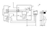
- FIG. 1illustrate generally an example of a system 100 including a baseband processor 105 having one or more general purpose input/output pins, an audio codec 110 coupled to the baseband processor 105 , an audio jack detection circuit 115 , an audio jack receptacle 120 , and an audio jack 125 .
- the audio jack detection circuit 115can include a comparator 116 configured to receive a microphone signal at a headset microphone pin (J_MIC), a buffer 117 (e.g., a comparator, a Schmitt trigger, etc.) configured to receive an audio jack detection signal at an audio jack detection pin (J_DET), a current source 118 (e.g., a 0.5 ⁇ A current source, etc.), and an oscillator and logic 119 .
- the audio jack receptacle 120can include a normally open (NO) configuration, in certain examples, operating as a normally open switch.
- the current source 118can be configured to provide a voltage at the buffer 117 when the audio jack receptacle 120 is empty that can be pulled to ground when an audio jack 125 is inserted into the audio jack receptacle 120 .
- the buffer 117can be configured to provide a detection signal to the oscillator and logic 119 and the processor 105 .
- the detection signalcan include a logic high signal when the audio jack receptacle 120 is empty and a logic low signal when the audio jack receptacle 120 includes the audio jack 125 .
- the normally open configuration of the audio jack receptacle 120 and the current source 118 (e.g., a 0.5 ⁇ A current source, etc.) of the audio jack detection circuit 115can be replaced with an audio jack receptacle 120 having a normally closed (NC) configuration and a current sink (e.g., a 0.5 ⁇ A current sink, etc.).
- a normally closed (NC) configuratione.g., a 0.5 ⁇ A current sink, etc.
- a current sinke.g., a 0.5 ⁇ A current sink, etc.
- the audio jack detection circuit 115can use one or more other components to detect the audio jack 125 and to provide an indication of the detected audio jack to the processor 105 .
- the audio jack 125can include a plurality of poles (e.g., two, three, four, etc.).
- a three-pole audio jacke.g., a standard audio or stereo headphone jack
- Lleft audio connection
- Rright audio connection
- GNDground
- the three-pole audio jackcan include four separate contacts with more than one contact being ground (e.g., a left audio connection, a right audio connection, and two ground connections).
- the audio jack 125 illustrated in FIG. 1includes a four-pole audio jack.
- the four-pole audio jackcan include a left audio connection (L), a right audio connection (R), ground (GND), and a microphone connection (MIC) or other input or output connection.
- the four-pole audio jackcan include a send/end key, using the microphone connection as a send/end key connection.
- the microphone connectioncan be pulled to ground, appearing similar to a three-pole audio jack while the send/end key is activated.
- the oscillatorcan be enabled and the audio detection circuit 115 can determine the type of the audio jack 125 coupled to the audio jack receptacle 120 (e.g., either a three-pole audio jack or a four-pole audio jack) using the comparator 116 , the oscillator and logic 119 , and the microphone signal from the audio jack receptacle 120 .
- the oscillator and logic 119can be configured to provide a determination of a pressed send/end to the processor 105 using a send/end key pin (S/E), to provide a determination of a three or four-pole audio jack to the processor 105 using an audio jack determination pin (J_POLE), and to receive an enable signal from the processor 105 using an enable pin (EN).
- S/Esend/end key pin
- J_POLEaudio jack determination pin
- ENenable pin
- the audio jack detection circuit 115can be configured to continuously confirm that the audio jack 125 is a three-pole audio jack, and not, for example, a four-pole audio jack with a depressed send/end key (e.g., a stuck send/end key, a send/end key depressed during initialization or startup, etc.), grounding the microphone connection, making the four-pole audio jack appear as a three-pole audio jack.
- a depressed send/end keye.g., a stuck send/end key, a send/end key depressed during initialization or startup, etc.
- the audio jack detection circuit 115can be configured to monitor for a send/end key activation on the microphone connection of the four-pole audio jack. In an example, once the audio jack is detected as a four-pole audio jack, it cannot be changed to a three-pole audio jack until power-down or reset.
- the audio jack detection circuit 115can include a switch 121 configured to open the connection between a microphone bias and the microphone connection of the audio jack 125 to reduce leakage current on a microphone path when send/end key detection is not required.
- the oscillator and logic 119can receive the detection signal and the microphone signal, determine the type of audio jack 125 coupled to the audio jack receptacle 120 , and provide an indication of the audio jack type and, in certain examples, an indication of a depressed send/end key, to the processor 105 .
- the oscillator and logic 119can include digital logic (e.g., in silicon) configured to determine the type of audio jack 125 or the depressed send/end key. In an example, when the oscillator is disabled, the digital logic can consume a very small amount of power.
- the audio jack detection circuit 115can be configured to determine and, in certain examples, constantly validate the number of poles on the audio jack 125 and provide that information to a processor 105 . In an example, the audio jack detection circuit 115 can continuously validate a three-pole audio jack, checking that the three-pole audio jack is not a four-pole audio jack with a stuck send/end key or a send/end key depressed during startup. If the stuck send/end key later becomes unstuck, the audio jack detection circuit 115 can correct the pole status. In certain examples, the audio jack detection circuit 115 can be configured to automatically detect a three-pole audio jack without using software or the processor 105 . In other examples, other audio jacks or receptacles can be used with more or less than the three- or four-pole audio jacks disclosed herein.
- FIG. 2illustrates generally an example of a method 200 including detecting a three-pole audio jack and double-checking for a four-pole audio jack.
- the following acronymsare used: “tDBJDET,” the audio jack detection debounce time; “DET,” a pin to provide an indication of a detected audio plug (e.g., active low); “S,” an internal switch (e.g., the switch 121 ); “J_MIC,” a headset microphone pin; “tDET,” the debounce and sample time for pole position; “J_POLE,” a pin to provide determination of a three-pole (e.g., high) or four-pole (e.g., low); “S/E,” a pin to provide determination of a pressed send/end key (e.g., high); and “tPER,” an internal switch closing and opening periods for microphone or send/end key detection.
- tDBJDETthe audio jack detection debounce time
- DETa pin to provide an indication of a
- the detection signal(e.g., the output of the buffer 117 , etc.) can change from a logic high signal to a logic low signal, indicating a valid audio jack detection signal.
- the microphone signalcan be debounced for a time period (e.g., 0.4 ⁇ tDET, etc.) and the internal switch can be closed.
- the headset microphone pincan be sampled one or more times, and the value of the one or more samples can be loaded into a register.
- the headset microphone pincan be sampled more than once and, in certain examples, at regular intervals.
- the headset microphone pincan be sampled three times at regular intervals (e.g., 0.2 ⁇ tDET each, etc.), and the values of the three samples can be loaded into the register.
- the internal switchcan be opened.
- the audio jack detection circuitmay not test for three or four-pole audio jack until the audio jack is removed and plugged back in, or until the audio jack detection circuit is reset.
- the audio jack detection circuitcan indicate to the processor that a three-pole audio jack is coupled to the audio jack receptacle.
- the internal switchcan remain open for a period of time (e.g., 0.9 ⁇ tPER, etc.), reducing leakage current on the microphone path when the headset microphone pin is not being sampled, saving power.
- the internal switchcan be closed for a period of time (e.g., 0.1 ⁇ tPER, etc.), generally a fraction of the open time of step 230 (e.g., to increase power savings), and a change in the headset microphone pin can be monitored. If no change is detected, then, at 225 , the audio jack detection circuit can indicate to the processor that a three-pole audio jack is coupled to the audio jack receptacle and the internal switch can be opened. If a change is detected, then, at 240 , the microphone signal can be debounced for a time period (e.g., 0.4 ⁇ tDET, etc.) and the internal switch can remain closed.
- a time periode.g., 0.4 ⁇ tDET, etc.
- the headset microphone pincan be sampled one or more times, and the value of the one or more samples can be loaded into a register.
- the internal switchcan be opened.
- the audio jack detection circuitcan indicate to the processor that a three-pole audio jack is coupled to the audio jack receptacle.
- the switch 221can be configured to reduce or eliminate any clicking associated with plugging in the microphone due to said leakage.
- FIG. 3illustrates generally an example of a method including detecting a send/end key activation on a four-pole audio jack.
- the following acronymsare used: “S,” an internal switch (e.g., the switch 121 ); “J_MIC,” a headset microphone pin; “tDET,” the debounce and sample time for pole position; “J_POLE,” a pin to provide determination of a three-pole (e.g., high) or four-pole (e.g., low); “S/E,” a pin to provide determination of a pressed send/end key (e.g., high); “tPER,” an internal switch closing and opening periods for microphone or send/end key detection; “Q,” a variable representing the state of the send/end key; and “/Q,” the inverse of the variable Q, representing a change in the state of the send/end key.
- San internal switch
- J_MICa headset microphone pin
- tDETthe debounce and sample time for pole position
- J_POLE
- the internal switchbe opened, or can remain open, for a period of time (e.g., 0.9 ⁇ tPER, etc.), reducing leakage current on the microphone path when the headset microphone pin is not being sampled, saving power.
- a period of timee.g., 0.9 ⁇ tPER, etc.
- the internal switchcan be closed for a period of time (e.g., 0.1 ⁇ tPER, etc.), and a change in the headset microphone pin can be monitored. If no change is detected, the process flow returns to step 305 . If a change is detected, then, at 320 , the microphone signal can be debounced for a time period (e.g., 0.4 ⁇ tDET, etc.) and the internal switch can remain closed.
- a period of timee.g., 0.1 ⁇ tPER, etc.
- the headset microphone pincan be sampled one or more times, and the value of the one or more samples can be loaded into a register.
- the internal switchcan be opened.
- the value of the send/end pincan toggle, indicating a change in the send/end key state, and the variable “Q” can be updated to indicate that the send/end key is pressed.
- updating the variable “Q”can allow a single detection algorithm to detect a change in state of the send/end key (e.g., pressed to not pressed, not pressed to pressed, etc.).
- FIGS. 4-8illustrate generally examples of various state diagrams.
- one or more of the state diagrams of FIGS. 4-8can be used in combination, or separately.
- the processing taking place using logice.g., in silicon
- logice.g., in silicon
- PORpower on reset
- there can be a first number of oscillator clock cycles (e.g., 10, etc.) between switch enabled and comparing the headset microphone pin using the comparator, and a second number of oscillator clock cycles (e.g., 4, etc.) between determining that an audio jack is plugged in (e.g., DETlow) and switch enabled.
- FIG. 4illustrates generally an example of an audio jack detection pin (J_DET) state diagram 400 .
- a state machine resetcan be asserted.
- the state machinecan remain in State 1 while the audio jack receptacle is empty.
- the oscillatorcan be disabled in State 1 to save power.
- the state machinecan proceed to State 2 .
- the oscillatorcan be enabled, and an audio jack detection counter can be set to 0 (e.g., J_DET COUNTER-0). If the value of the audio jack detection pin changes, the state machine can remain in State 2 . If the value of the audio jack detection pin does not change, the state machine can proceed to State 3 .
- the audio jack detection countercan be incremented. If the value of the audio jack detection pin changes, the state machine can return to State 2 . If the value of the audio jack detection pin does not change, the state machine can remain in State 3 and the audio jack detection counter can be incremented. If the value of the audio jack detection pin changes and the audio jack detection counter reaches a maximum value (e.g., 3, 10, etc.), the state machine can return to State 1 . If the value of the audio jack detection pin does not change and the audio jack detection pin counter reaches the maximum value, the state machine can proceed to State 4 .
- a maximum valuee.g., 3, 10, etc.
- the state machine resetcan be de-asserted, and a detection signal can be provided to the processor indicating that the audio jack receptacle includes a valid audio jack. If the value of the audio jack detection pin does not change (e.g., if the value of the audio jack detection pin indicates that the audio jack is plugged into the audio jack receptacle), the state machine remains in State 4 . If the value of the audio jack detection pin changes, the state machine can return to State 2 .
- FIG. 5illustrates generally an example of a first portion of a headset microphone pin (J_MIC) state diagram 500 .
- the value of the comparatorcan be high when the headset microphone pin (J_MIC) is at or near ground, and low when the headset microphone pin (J_MIC) is above ground (e.g., 0.2 V, etc.).
- States 3 and 4toggle the switch on and off at a predetermined duty cycle (e.g., shown here at a 10% duty cycle (90 mS “off”, 10 mS “on”), but in other examples, one or more other duty cycles).
- a state machine resetcan be asserted, a debounce process can be initialized (INIT_DB), and the internal switch can be opened.
- a state machine resetcan bring the state machine back to State 1 .
- a countercan be started, the internal switch can be closed, and the audio jack type can be determined.
- the countercan continue and the internal switch can be opened.
- the state machinecan remain in State 3 for until the counter reaches a second time (e.g., 90 mS). When the counter reaches the second time, the state machine can proceed to State 4 .
- the state machinecan proceed to State 5 . If, in State 4 , the counter reaches 10 mS, the state machine can return to State 3 .
- the internal switchcan remain closed, and the audio jack determination pin (J_POLE) can indicate that the audio jack is a four-pole audio jack.
- the value of the headset microphone pin (J_MIC)can be sampled. If the value is different than the previous valid value (e.g., one or more times, 3 times, etc.), the valid value can be updated and the state machine can return to State 3 .
- a state machine resetcan be asserted, a debounce process can be initialized (INIT_DB), and the internal switch can be opened.
- State 3the state machine waits until the enable signal is high before proceeding to State 4 . If the enable signal transitions from high to low in States 2 , 4 , or 5 , the state machine proceeds to State 3 .
- State 5the state machine waits for an amount of time (e.g., 20 mS) before returning to State 4 .
- an amount of timee.g. 20 mS
- FIGS. 7-8illustrate generally examples of first and second portions of a headset microphone pin (J_MIC) state diagrams 700 , 800 .
- FIG. 7illustrates generally a first portion, similar in function to that illustrated in the example of FIG. 5 .
- FIG. 8illustrates generally a second portion with respect to an enable signal, similar in function to that illustrated in the example of FIG. 6 .
- a single, simplified state machinecan be used to detect a three-pole or a four-pole audio jack or a send/end key activation on a four-pole audio jack.
- the simplified designcan provide a reduced area in a die (e.g., 3600 um 2 , etc.), a lower cost, a reduced risk in design (e.g., less code/logic, chance of error, etc.), etc.
- an output pin(e.g., DET) can only change state when the opposite state has been sampled a predetermined number of times (e.g., 3 times) in a sampling period, for example, to ensure correct transitions between states.
- samplescan be made at three portions of a sample period (e.g., 60% of the period, 80%, 100%, etc.). In this example, each of the three samples must be the opposite of the output pin in order to change the value of the output pin.
- the logic of the audio jack detection circuitcan have a base count value (e.g., 10 ms) that can be adjusted in metal.
- each adjustmentcan be an increment of the base count value.
- the base count valuecan be adjusted, effectively adjusting the time periods throughout the device.
- the base count valuecan be defined using tie cells to either VDD or GND as desired, which can be changed in metal without changing the remaining counter logic.
- the counter logiccan count until it reaches this metal programmable number.
- Each overflowincrements a separate counter to allow for all counters to be proportional to each other at all times, allowing for fast and cheap variants of a core product by reducing or increasing debounce counters for various customer needs.
- an apparatusin Example 1, includes an audio jack detection circuit configured to be coupled to an audio jack receptacle, the audio jack detection circuit including an oscillator and digital logic configured to receive a clock signal from the oscillator and to determine a type of audio jack in the audio jack receptacle, wherein the audio jack detection circuit is configured to receive audio jack receptacle information, to disable the oscillator when the audio jack receptacle information indicates that the audio jack receptacle is empty, and to enable the oscillator when the audio jack receptacle information indicates that the audio jack receptacle includes an audio jack.
- the audio jack detection circuit of Example 1optionally includes a buffer having an input configured to be coupled to the audio jack receptacle and a current source coupled to the buffer, the current source configured to provide a voltage at the input of the buffer when the audio jack receptacle is empty, wherein, when the audio jack receptacle includes the audio jack, the voltage at the buffer is reduced.
- Example 3the current source of any one or more of Examples 1-2 is optionally equal to or less than one microamp ( ⁇ A) to reduce power usage when the audio jack receptacle is empty.
- ⁇ Amicroamp
- the audio jack detection circuit of any one or more of Examples 1-3optionally includes a buffer having an input configured to be coupled to the audio jack receptacle and a current sink coupled to the buffer, the current sink configured to provide a voltage at the input of the buffer when the audio jack receptacle includes the audio jack, wherein, when the audio jack receptacle is empty, the voltage at the buffer is reduced.
- Example 5the digital logic of any one or more of Examples 1-4 is optionally configured to determine the type of audio jack in the audio jack receptacle as a three-pole audio jack or a four-pole audio jack, wherein the audio jack detection circuit is configured to provide information about the determined type of audio jack to a processor.
- Example 6the type of audio jack of any one or more of Examples 1-5 optionally includes at least one of a three-pole audio jack or a four-pole audio jack, wherein the three-pole audio jack of any one or more of Examples 1-5 optionally includes a left audio connection, a right audio connection, and ground, and wherein the four-pole audio jack of any one or more of Examples 1-5 optionally includes a left audio connection, a right audio connection, ground, and a microphone connection.
- the audio jack detection circuit of any one or more of Examples 1-6optionally includes a comparator having a first input configured to be coupled to a microphone connection of the audio jack receptacle and to a microphone bias, wherein the comparator is configured to determine if the microphone connection of the audio jack receptacle is grounded using the microphone connection of the audio jack receptacle and the microphone bias, wherein the digital logic is configured to determine the type of audio jack in the audio jack receptacle using the comparator.
- Example 8if the determined type of audio jack is a four-pole audio jack, the digital logic of any one or more of Examples 1-7 is optionally configured to detect a send/end key state change using the comparator.
- any one or more of Examples 1-10optionally includes a switch configured to selectively couple the first input of the comparator to the microphone bias when the audio jack receptacle information indicates that the audio jack receptacle includes an audio jack.
- Example 10when the audio jack receptacle information indicates that the audio jack receptacle includes an audio jack, the switch of any one or more of Examples 1-9 is optionally configured to couple and decouple the microphone bias from the microphone connection of the audio jack receptacle at a specified duty cycle to reduce leakage current through the audio jack.
- the audio jack detection circuit of any one or more of Examples 1-10optionally includes a comparator and a switch coupled to the comparator, wherein the comparator of any one or more of Examples 1-10 optionally includes a first input configured to be coupled to a microphone connection of the audio jack receptacle and to the switch, wherein the switch is controlled by the digital logic and is configured to selectively couple the first input of the comparator to a microphone bias when the audio jack receptacle information indicates that the audio jack receptacle includes an audio jack, wherein the comparator is configured to determine if the microphone connection of the audio jack receptacle is grounded using the microphone bias and the microphone connection of the audio jack receptacle, and wherein the digital logic is configured to determine the type of audio jack in the audio jack receptacle using the comparator.
- Example 12if the determined type of audio jack is a four-pole audio jack, the digital logic of any one or more of Examples 1-11 is optionally configured to detect a send/end key state change using the comparator.
- Example 13the digital logic of any one or more of Examples 1-12 optionally includes a register configured to store the detected send/end key state change, and wherein the digital logic is configured to validate the detected send/end key state change using more than one successive, consistent stored output from the comparator.
- Example 14if the determined type of audio jack is a three-pole audio jack, the digital logic of any one or more of Examples 1-13 is optionally configured to periodically redetermine the type of audio jack using the comparator.
- Example 15if the determined type of audio jack is a four-pole audio jack, the digital logic of any one or more of Examples 1-14 is optionally configured to not redetermine the type of audio jack until the audio jack detection circuit is reset of until the audio jack receptacle information indicates that the audio jack has been removed from the audio jack receptacle.
- a methodincludes receiving audio jack receptacle information at an audio jack detection circuit, disabling an oscillator when the audio jack receptacle information indicates that the audio jack receptacle is empty, and enabling the oscillator and determining a type of audio jack in the audio jack receptacle, using digital logic configured to receive a clock signal from the oscillator, when the audio jack receptacle information indicates that the audio jack receptacle includes an audio jack.
- Example 17the receiving the audio jack receptacle information of any one or more of Examples 1-16 optionally includes receiving a first voltage at an input to a buffer from a current source when the audio jack receptacle is empty and receiving a second voltage at the input to the buffer from the current source when the audio jack receptacle includes an audio jack.
- Example 18the receiving the audio jack receptacle information of any one or more of Examples 1-17 optionally includes receiving a first voltage at an input to a buffer from a current source when the audio jack receptacle is empty and receiving a second, lower voltage at the input to the buffer when the audio jack receptacle includes an audio jack.
- Example 19the receiving the audio jack receptacle information of any one or more of Examples 1-18 optionally includes receiving a first voltage at an input to a buffer from when the audio jack receptacle is empty and receiving a second, higher voltage at the input to the buffer when the audio jack receptacle includes an audio jack.
- the determining the type of audio jack in the audio jack receptacle of any one or more of Examples 1-19optionally includes determining the type of audio jack as a three-pole audio jack or a four-pole audio jack and providing information about the determined type of audio jack to a processor, wherein the three-pole audio jack of any one or more of Examples 1-19 optionally includes a left audio connection, a right audio connection, and ground, wherein the four-pole audio jack of any one or more of Examples 1-19 optionally includes a left audio connection, a right audio connection, ground, and a microphone connection.
- Example 22any one or more of Examples 1-21 optionally includes detecting a send/end key state change using the comparator if the determined type of audio jack is a four-pole audio jack.
- Example 23any one or more of Examples 1-22 optionally includes selectively coupling the comparator to the microphone bias when the audio jack receptacle information indicates that the audio jack receptacle includes an audio jack.
- Example 24the selectively coupling the comparator to the microphone bias of any one or more of Examples 1-23 optionally includes at a specified duty cycle to reduce leakage current through the audio jack.
- Example 25any one or more of Examples 1-24 optionally includes storing the detected send/end key state change in a register and validating the detected send/end key state change using more than one successive, consistent stored state change.
- Example 26any one or more of Examples 1-19 optionally includes periodically redetermining the type of audio jack using the comparator if the determined type of audio jack is a three-pole audio jack.
- any one or more of Examples 1-26optionally includes not periodically redetermining the type of audio jack, if the determined type of audio jack is a four-pole audio jack, until the audio jack detection circuit is reset or until the audio jack receptacle information indicates that the audio jack as been removed from the audio jack receptacle.
- a systemin Example 28, includes a processor, an audio jack detection circuit coupled to the processor and an audio jack receptacle coupled to the audio jack detection circuit, the audio jack receptacle configured to receive an audio jack from an external device wherein the audio jack detection circuit optionally includes an oscillator and digital logic configured to receive a clock signal from the oscillator and to determine a type of audio jack in the audio jack receptacle, wherein the audio jack detection circuit is configured to receive audio jack receptacle information, to disable the oscillator when the audio jack receptacle information indicates that the audio jack receptacle is empty, and to enable the oscillator when the audio jack receptacle information indicates that the audio jack receptacle includes an audio jack.
- Example 29any one or more of Examples 1-28 optionally includes a cellular phone, the cellular phone including the processor, wherein the processor include a baseband processor, the audio jack detection circuit, and the audio jack receptacle.
- Example 30a system or apparatus can include, or can optionally be combined with any portion or combination of any portions of any one or more of Examples 1-29 to include, means for performing any one or more of the functions of Examples 1-29 or a machine-readable medium including instructions that, when performed by a machine, cause the machine to perform any one or more of the functions of Examples 1-29.
- the terms “a” or “an”are used, as is common in patent documents, to include one or more than one, independent of any other instances or usages of “at least one” or “one or more.”
- the term “or”is used to refer to a nonexclusive or, such that “A or B” includes “A but not B,” “B but not A,” and “A and B,” unless otherwise indicated.
- Method examples described hereincan be machine or computer-implemented at least in part. Some examples can include a computer-readable medium or machine-readable medium encoded with instructions operable to configure an electronic device to perform methods as described in the above examples.
- An implementation of such methodscan include code, such as microcode, assembly language code, a higher-level language code, or the like. Such code can include computer readable instructions for performing various methods. The code may form portions of computer program products. Further, the code can be tangibly stored on one or more volatile or non-volatile tangible computer-readable media, such as during execution or at other times.
- Examples of these tangible computer-readable mediacan include, but are not limited to, hard disks, removable magnetic disks, removable optical disks (e.g., compact disks and digital video disks), magnetic cassettes, memory cards or sticks, random access memories (RAMs), read only memories (ROMs), and the like.
Landscapes
- Physics & Mathematics (AREA)
- Nonlinear Science (AREA)
- Engineering & Computer Science (AREA)
- Acoustics & Sound (AREA)
- Signal Processing (AREA)
- Circuit For Audible Band Transducer (AREA)
- Electronic Switches (AREA)
- Telephone Function (AREA)
Abstract
Description
- 1) detect that an audio jack has been coupled to or decoupled from the device (e.g., plugged into the audio jack receptacle, unplugged from the audio jack receptacle, etc.);
- 2) provide a low-power state, consuming a small amount of power when an audio jack is decoupled from the device (e.g., disabling the oscillator, etc.);
- 3) determine the type of audio jack coupled to the device (e.g., a three-pole audio jack, a four-pole audio jack, or one or more other type of audio jack);
- 4) determine if the audio jack includes a microphone connection;
- 5) switch in/out a microphone port between an audio codec and a headset microphone;
- 6) determine if the audio jack includes a send/end key connection;
- 7) detect that the send/end key has been pressed (e.g., detect that a microphone bias has been grounded, that a voltage has been applied, etc.);
- 8) check (e.g., an initial check, a periodic check, a continuous check, etc.) for a stuck or defective send/end switch, for example, if the coupled audio jack is a three-pole audio jack; or
- 9) provide audio jack information to the processor (e.g., information about whether an audio jack is plugged into the audio jack receptacle, the type of audio jack, information about a detected microphone connection, send/end key information, etc.).
Claims (27)
Priority Applications (1)
| Application Number | Priority Date | Filing Date | Title |
|---|---|---|---|
| US13/188,778US8831234B2 (en) | 2010-07-23 | 2011-07-22 | Audio jack detection and configuration |
Applications Claiming Priority (2)
| Application Number | Priority Date | Filing Date | Title |
|---|---|---|---|
| US36726610P | 2010-07-23 | 2010-07-23 | |
| US13/188,778US8831234B2 (en) | 2010-07-23 | 2011-07-22 | Audio jack detection and configuration |
Publications (2)
| Publication Number | Publication Date |
|---|---|
| US20120019309A1 US20120019309A1 (en) | 2012-01-26 |
| US8831234B2true US8831234B2 (en) | 2014-09-09 |
Family
ID=45493120
Family Applications (2)
| Application Number | Title | Priority Date | Filing Date |
|---|---|---|---|
| US13/188,834Active2032-07-27US8817994B2 (en) | 2010-07-23 | 2011-07-22 | Audio jack reset |
| US13/188,778Active2032-06-09US8831234B2 (en) | 2010-07-23 | 2011-07-22 | Audio jack detection and configuration |
Family Applications Before (1)
| Application Number | Title | Priority Date | Filing Date |
|---|---|---|---|
| US13/188,834Active2032-07-27US8817994B2 (en) | 2010-07-23 | 2011-07-22 | Audio jack reset |
Country Status (3)
| Country | Link |
|---|---|
| US (2) | US8817994B2 (en) |
| KR (1) | KR101760354B1 (en) |
| CN (2) | CN102378087B (en) |
Cited By (9)
| Publication number | Priority date | Publication date | Assignee | Title |
|---|---|---|---|---|
| US20130178149A1 (en)* | 2012-01-06 | 2013-07-11 | Ontario, Canada) | Mobile wireless communications device using wired headset as an antenna and related methods |
| US20140241535A1 (en)* | 2013-02-26 | 2014-08-28 | Research In Motion Limited | Apparatus, systems and methods for detecting insertion or removal of an audio accessory from an electronic device |
| US9294857B2 (en) | 2011-07-22 | 2016-03-22 | Fairchild Semiconductor Corporation | Detection and GSM noise filtering |
| US20160100242A1 (en)* | 2014-10-01 | 2016-04-07 | Michael G. Lannon | Exercise System With Headphone Detection Circuitry |
| US20170127203A1 (en)* | 2015-10-29 | 2017-05-04 | Samsung Electronics Co., Ltd. | Method for controlling audio signal and electronic device supporting the same |
| US20170134851A1 (en)* | 2014-06-26 | 2017-05-11 | Ams Ag | Host interface, accessory interface and method for managing a connection between a host interface and an accessory device |
| US9674598B2 (en) | 2014-04-15 | 2017-06-06 | Fairchild Semiconductor Corporation | Audio accessory communication with active noise cancellation |
| US20170164094A1 (en)* | 2012-12-27 | 2017-06-08 | Cirrus Logic International Semiconductor Ltd. | Detection circuit |
| US20170280262A1 (en)* | 2016-03-28 | 2017-09-28 | Acer Incorporated | Electronic device, detection device and method for setting output of headset |
Families Citing this family (30)
| Publication number | Priority date | Publication date | Assignee | Title |
|---|---|---|---|---|
| US8244927B2 (en) | 2009-10-27 | 2012-08-14 | Fairchild Semiconductor Corporation | Method of detecting accessories on an audio jack |
| US8817994B2 (en) | 2010-07-23 | 2014-08-26 | Fairchild Semiconductor Corporation | Audio jack reset |
| US9229833B2 (en) | 2011-01-28 | 2016-01-05 | Fairchild Semiconductor Corporation | Successive approximation resistor detection |
| WO2013032822A2 (en) | 2011-08-26 | 2013-03-07 | Dts Llc | Audio adjustment system |
| KR101874888B1 (en)* | 2011-11-22 | 2018-07-06 | 삼성전자 주식회사 | Method and apparatus for recognizing earphone in portable device |
| US9678560B2 (en)* | 2011-11-28 | 2017-06-13 | Intel Corporation | Methods and apparatuses to wake computer systems from sleep states |
| CN102707188B (en)* | 2012-06-04 | 2014-08-13 | 昆山嘉华电子有限公司 | Audio connector testing device |
| CN103475965B (en)* | 2012-06-07 | 2018-07-27 | 深圳富泰宏精密工业有限公司 | Electronic device |
| US8909173B2 (en)* | 2012-06-29 | 2014-12-09 | Motorola Solutions, Inc. | Method and apparatus for operating accessory interface functions over a single signal |
| US9060228B2 (en)* | 2012-08-03 | 2015-06-16 | Fairchild Semiconductor Corporation | Accessory detection circuit with improved functionality |
| US9223388B2 (en)* | 2013-01-29 | 2015-12-29 | Hewlett Packard Enterprise Development Lp | Power state transition saving session information |
| KR102086615B1 (en)* | 2013-02-13 | 2020-03-10 | 온세미컨덕터코리아 주식회사 | Jack detector, detecting device, and detecting method |
| CN104599672B (en)* | 2013-10-31 | 2018-04-03 | 瑞昱半导体股份有限公司 | There are the audio codec and audio grafting detection method of audio grafting detectability |
| USD726223S1 (en)* | 2014-01-14 | 2015-04-07 | Cedano Guerrero | Wireless audio video jack |
| US9584893B2 (en)* | 2014-01-20 | 2017-02-28 | Fairchild Semiconductor Corporation | Apparatus and method for recovering from partial insertion of an audio jack |
| US9794708B2 (en)* | 2014-01-20 | 2017-10-17 | Fairchild Semiconductor Corporation | Apparatus and method for detecting insertion anomaly of an audio jack |
| US9793658B2 (en)* | 2014-06-01 | 2017-10-17 | Apple Inc. | Reuse of plug detection contacts to reduce crosstalk |
| JP6316728B2 (en)* | 2014-10-22 | 2018-04-25 | 京セラ株式会社 | Electronic device, earphone, and electronic device system |
| JP6352157B2 (en)* | 2014-11-14 | 2018-07-04 | 株式会社オーディオテクニカ | Microphone |
| US9813816B2 (en)* | 2015-01-26 | 2017-11-07 | Realtek Semiconductor Corp. | Audio plug detection structure in audio jack corresponding to audio plug and method thereof |
| CN106154105B (en)* | 2015-02-02 | 2019-10-25 | 瑞昱半导体股份有限公司 | Audio plug detection structure and method thereof |
| US9743188B2 (en)* | 2015-03-11 | 2017-08-22 | Texas Instruments Incorporated | Audio plug type detection |
| US9785487B1 (en)* | 2015-05-12 | 2017-10-10 | Google Inc. | Managing device functions based on physical interaction with device modules |
| CN106303822B (en)* | 2015-06-25 | 2021-06-08 | 朗新科技集团股份有限公司 | Mobile phone audio interface communication equipment |
| US10141902B1 (en)* | 2015-07-08 | 2018-11-27 | Marvell World Trade Ltd. | Apparatus for and method of generating output signal based on detected load resistance value |
| DE102015013572B4 (en)* | 2015-10-14 | 2017-08-24 | CSS MicroSystems GmbH | Universal connection system for sensors and methods for detecting sensors |
| US10312902B2 (en)* | 2016-10-28 | 2019-06-04 | Analog Devices Global | Low-area, low-power, power-on reset circuit |
| TWI659657B (en)* | 2017-09-26 | 2019-05-11 | 瑞昱半導體股份有限公司 | Detecting circuit and associated detecting method |
| DE102018126327A1 (en) | 2017-10-23 | 2019-04-25 | Maxim Integrated Products, Inc. | Systems and methods for accessory and impedance detection |
| US11720559B2 (en)* | 2020-06-02 | 2023-08-08 | Salesforce.Com, Inc. | Bridging textual and tabular data for cross domain text-to-query language semantic parsing with a pre-trained transformer language encoder and anchor text |
Citations (43)
| Publication number | Priority date | Publication date | Assignee | Title |
|---|---|---|---|---|
| US5754552A (en) | 1995-07-12 | 1998-05-19 | Compaq Computer Corporation | Automatic communication protocol detection system and method for network systems |
| US6301344B1 (en) | 1997-11-05 | 2001-10-09 | Protel, Inc. | Intelligent public telephone system and method |
| CN1441353A (en) | 2002-02-28 | 2003-09-10 | 德克萨斯仪器股份有限公司 | Bus monitor controller for reinforced universal serial bus |
| US6650635B1 (en) | 1996-08-23 | 2003-11-18 | Hewlett-Packard Development Company, L.P. | Network telephone communication |
| US20050201568A1 (en) | 2004-03-11 | 2005-09-15 | Texas Instruments Incorporated | Headset Detector in a Device Generating Audio Signals |
| CN1708023A (en) | 2004-06-08 | 2005-12-14 | 伯斯有限公司 | Managing an audio network |
| CN1728082A (en) | 2005-07-29 | 2006-02-01 | 上海贝豪通讯电子有限公司 | Method for raising versatility of earphone interface |
| US7053598B2 (en) | 2002-12-04 | 2006-05-30 | C-Media Electronics, Inc. | Structure for detecting plug/unplug status of phone-jacks by single bit generated by a resistor network |
| US20060147059A1 (en) | 2004-12-30 | 2006-07-06 | Inventec Appliances Corporation | Smart volume adjusting method for a multi-media system |
| CN1859813A (en) | 2005-09-28 | 2006-11-08 | 华为技术有限公司 | Signal switching method for internal and external microphone |
| US20070133828A1 (en) | 2005-12-14 | 2007-06-14 | Ajaykumar Kanji | Audio input-output module, plug-in detection module and methods for use therewith |
| CN101069410A (en) | 2004-10-25 | 2007-11-07 | 诺基亚公司 | Detection, identification and operation of peripherals connected to electronic equipment via audio/video plugs |
| US20080112572A1 (en) | 2006-11-10 | 2008-05-15 | Hon Hai Precision Industry Co., Ltd. | Earphone and media player |
| US20080140902A1 (en) | 2006-12-08 | 2008-06-12 | Karl Townsend | Multi-interfaced accessory device for use with host computing systems |
| US20080150512A1 (en) | 2006-12-25 | 2008-06-26 | Nikon Corporation | Electronic device |
| US20080247241A1 (en) | 2007-04-05 | 2008-10-09 | Hao Thai Nguyen | Sensing in non-volatile storage using pulldown to regulated source voltage to remove system noise |
| US20080298607A1 (en)* | 2007-05-30 | 2008-12-04 | Fortemedia, Inc. | Audio interface device and method |
| CN101425048A (en) | 2007-10-31 | 2009-05-06 | 索尼爱立信移动通讯有限公司 | Electronic device utilizing impedance and/or resistance identification to identify an accessory device |
| CN101426035A (en) | 2007-10-31 | 2009-05-06 | 索尼爱立信移动通讯有限公司 | Additional pins on a usb connector |
| US20090136058A1 (en) | 2007-11-28 | 2009-05-28 | Samsung Electronics Co. Ltd. | Compatible circuit and method for 4- and 5-pole earphones and portable device using the same |
| CN101453510A (en) | 2007-12-05 | 2009-06-10 | 德信智能手机技术(北京)有限公司 | Earphone recognition apparatus and method for mobile communication terminal |
| US20090180630A1 (en) | 2008-01-14 | 2009-07-16 | Sander Wendell B | Electronic device circuitry for communicating with accessories |
| US7565458B2 (en) | 2003-12-12 | 2009-07-21 | Sony Ericsson Mobile Communications Ab | Cell phone accessory identification algorithm by generating and measuring a voltage pulse through a pin interface |
| US20090198841A1 (en) | 2008-02-06 | 2009-08-06 | Matsushita Electric Industrial Co., Ltd. | Interface detecting circuit and interface detecting method |
| US20090285415A1 (en) | 2008-05-15 | 2009-11-19 | Fortemedia, Inc. | Interfacing circuit for a removable microphone |
| CN101729958A (en) | 2008-10-24 | 2010-06-09 | 深圳富泰宏精密工业有限公司 | Audio frequency output device |
| US20100173676A1 (en) | 2009-01-05 | 2010-07-08 | Shenzhen Futaihong Precision Industry Co., Ltd. | Electronic device |
| US20100199112A1 (en) | 2009-01-30 | 2010-08-05 | Kabushiki Kaisha Toshiba | Information processing apparatus and power supply control method |
| US7916875B2 (en) | 2005-12-14 | 2011-03-29 | Integrated Device Technology, Inc. | Audio input-output module, plug-in device detection module and methods for use therewith |
| US20110085673A1 (en) | 2009-10-14 | 2011-04-14 | Samsung Electronics Co. Ltd. | Circuit apparatus for recognizing earphone in mobile terminal |
| US20110099298A1 (en) | 2009-10-27 | 2011-04-28 | Fairchild Semiconductor Corporation | Method of detecting accessories on an audio jack |
| US20110099300A1 (en) | 2009-10-27 | 2011-04-28 | Fairchild Semiconductor Corporation | Camera shutter control through a usb port or audio/video port |
| KR20110046361A (en) | 2009-10-27 | 2011-05-04 | 페어차일드 세미컨덕터 코포레이션 | How to Detect Attachments with Audio Jacks |
| US20110199123A1 (en) | 2010-02-12 | 2011-08-18 | Fairchild Semiconductor Corporation | Multiple detection circuit for accessory jacks |
| US8064613B1 (en) | 2008-03-03 | 2011-11-22 | Maxim Integrated Products, Inc. | Electret microphone detection using a current source |
| US20120019306A1 (en) | 2010-07-23 | 2012-01-26 | Turner John R | Audio jack reset |
| US20120057078A1 (en) | 2010-03-04 | 2012-03-08 | Lawrence Fincham | Electronic adapter unit for selectively modifying audio or video data for use with an output device |
| US8150046B2 (en)* | 2009-02-26 | 2012-04-03 | Research In Motion Limited | Audio jack for a portable electronic device |
| US20120198183A1 (en) | 2011-01-28 | 2012-08-02 | Randall Wetzel | Successive approximation resistor detection |
| US20120200172A1 (en) | 2011-02-09 | 2012-08-09 | Apple Inc. | Audio accessory type detection and connector pin signal assignment |
| US20120237051A1 (en) | 2011-03-15 | 2012-09-20 | Samsung Electronics Co. Ltd. | Earphone system for mobile devices |
| CN102892068A (en) | 2011-07-22 | 2013-01-23 | 飞兆半导体公司 | MIC/GND detection and automatic switch |
| US8467828B2 (en) | 2007-01-05 | 2013-06-18 | Apple Inc. | Audio I O headset plug and plug detection circuitry |
Family Cites Families (1)
| Publication number | Priority date | Publication date | Assignee | Title |
|---|---|---|---|---|
| US8238811B2 (en) | 2008-09-08 | 2012-08-07 | Apple Inc. | Cross-transport authentication |
- 2011
- 2011-07-22USUS13/188,834patent/US8817994B2/enactiveActive
- 2011-07-22USUS13/188,778patent/US8831234B2/enactiveActive
- 2011-07-25KRKR1020110073717Apatent/KR101760354B1/enactiveActive
- 2011-07-25CNCN201110209512.5Apatent/CN102378087B/enactiveActive
- 2011-07-25CNCN201110209513.XApatent/CN102404666B/enactiveActive
Patent Citations (74)
| Publication number | Priority date | Publication date | Assignee | Title |
|---|---|---|---|---|
| US5754552A (en) | 1995-07-12 | 1998-05-19 | Compaq Computer Corporation | Automatic communication protocol detection system and method for network systems |
| US6650635B1 (en) | 1996-08-23 | 2003-11-18 | Hewlett-Packard Development Company, L.P. | Network telephone communication |
| US6301344B1 (en) | 1997-11-05 | 2001-10-09 | Protel, Inc. | Intelligent public telephone system and method |
| CN1441353A (en) | 2002-02-28 | 2003-09-10 | 德克萨斯仪器股份有限公司 | Bus monitor controller for reinforced universal serial bus |
| US7053598B2 (en) | 2002-12-04 | 2006-05-30 | C-Media Electronics, Inc. | Structure for detecting plug/unplug status of phone-jacks by single bit generated by a resistor network |
| US7565458B2 (en) | 2003-12-12 | 2009-07-21 | Sony Ericsson Mobile Communications Ab | Cell phone accessory identification algorithm by generating and measuring a voltage pulse through a pin interface |
| US20050201568A1 (en) | 2004-03-11 | 2005-09-15 | Texas Instruments Incorporated | Headset Detector in a Device Generating Audio Signals |
| CN1708023A (en) | 2004-06-08 | 2005-12-14 | 伯斯有限公司 | Managing an audio network |
| CN101069410A (en) | 2004-10-25 | 2007-11-07 | 诺基亚公司 | Detection, identification and operation of peripherals connected to electronic equipment via audio/video plugs |
| US20080318629A1 (en) | 2004-10-25 | 2008-12-25 | Nokia Corporation | Detection, Identification and Operation of Pheripherals Connected Via an Audio/Video-Plug to an Electronic Device |
| US20060147059A1 (en) | 2004-12-30 | 2006-07-06 | Inventec Appliances Corporation | Smart volume adjusting method for a multi-media system |
| CN1728082A (en) | 2005-07-29 | 2006-02-01 | 上海贝豪通讯电子有限公司 | Method for raising versatility of earphone interface |
| CN1859813A (en) | 2005-09-28 | 2006-11-08 | 华为技术有限公司 | Signal switching method for internal and external microphone |
| US20070133828A1 (en) | 2005-12-14 | 2007-06-14 | Ajaykumar Kanji | Audio input-output module, plug-in detection module and methods for use therewith |
| US7916875B2 (en) | 2005-12-14 | 2011-03-29 | Integrated Device Technology, Inc. | Audio input-output module, plug-in device detection module and methods for use therewith |
| US20080112572A1 (en) | 2006-11-10 | 2008-05-15 | Hon Hai Precision Industry Co., Ltd. | Earphone and media player |
| US20080140902A1 (en) | 2006-12-08 | 2008-06-12 | Karl Townsend | Multi-interfaced accessory device for use with host computing systems |
| US20080150512A1 (en) | 2006-12-25 | 2008-06-26 | Nikon Corporation | Electronic device |
| US8467828B2 (en) | 2007-01-05 | 2013-06-18 | Apple Inc. | Audio I O headset plug and plug detection circuitry |
| US20080247241A1 (en) | 2007-04-05 | 2008-10-09 | Hao Thai Nguyen | Sensing in non-volatile storage using pulldown to regulated source voltage to remove system noise |
| US20080298607A1 (en)* | 2007-05-30 | 2008-12-04 | Fortemedia, Inc. | Audio interface device and method |
| CN101425048A (en) | 2007-10-31 | 2009-05-06 | 索尼爱立信移动通讯有限公司 | Electronic device utilizing impedance and/or resistance identification to identify an accessory device |
| CN101426035A (en) | 2007-10-31 | 2009-05-06 | 索尼爱立信移动通讯有限公司 | Additional pins on a usb connector |
| US20090136058A1 (en) | 2007-11-28 | 2009-05-28 | Samsung Electronics Co. Ltd. | Compatible circuit and method for 4- and 5-pole earphones and portable device using the same |
| US8155337B2 (en)* | 2007-11-28 | 2012-04-10 | Samsung Electronics Co., Ltd | Compatible circuit and method for 4- and 5-pole earphones and portable device using the same |
| CN101453510A (en) | 2007-12-05 | 2009-06-10 | 德信智能手机技术(北京)有限公司 | Earphone recognition apparatus and method for mobile communication terminal |
| US7869608B2 (en) | 2008-01-14 | 2011-01-11 | Apple Inc. | Electronic device accessory |
| US20090180630A1 (en) | 2008-01-14 | 2009-07-16 | Sander Wendell B | Electronic device circuitry for communicating with accessories |
| CN101489159A (en) | 2008-01-14 | 2009-07-22 | 苹果公司 | Electronic device and electronic device accessory |
| US20090198841A1 (en) | 2008-02-06 | 2009-08-06 | Matsushita Electric Industrial Co., Ltd. | Interface detecting circuit and interface detecting method |
| US8064613B1 (en) | 2008-03-03 | 2011-11-22 | Maxim Integrated Products, Inc. | Electret microphone detection using a current source |
| US20090285415A1 (en) | 2008-05-15 | 2009-11-19 | Fortemedia, Inc. | Interfacing circuit for a removable microphone |
| CN101729958A (en) | 2008-10-24 | 2010-06-09 | 深圳富泰宏精密工业有限公司 | Audio frequency output device |
| US20100173676A1 (en) | 2009-01-05 | 2010-07-08 | Shenzhen Futaihong Precision Industry Co., Ltd. | Electronic device |
| US20100199112A1 (en) | 2009-01-30 | 2010-08-05 | Kabushiki Kaisha Toshiba | Information processing apparatus and power supply control method |
| US8150046B2 (en)* | 2009-02-26 | 2012-04-03 | Research In Motion Limited | Audio jack for a portable electronic device |
| US20110085673A1 (en) | 2009-10-14 | 2011-04-14 | Samsung Electronics Co. Ltd. | Circuit apparatus for recognizing earphone in mobile terminal |
| CN102045620A (en) | 2009-10-14 | 2011-05-04 | 三星电子株式会社 | Circuit apparatus for recognizing earphone in mobile terminal |
| KR20110046361A (en) | 2009-10-27 | 2011-05-04 | 페어차일드 세미컨덕터 코포레이션 | How to Detect Attachments with Audio Jacks |
| US20120326736A1 (en) | 2009-10-27 | 2012-12-27 | Fairchild Semiconductor Corporation | Detecting accessories on an audio or video jack |
| US8489782B2 (en)* | 2009-10-27 | 2013-07-16 | Fairchild Semiconductor Corporation | Detecting accessories on an audio or video jack |
| US20140025845A1 (en) | 2009-10-27 | 2014-01-23 | Fairchild Semiconductor Corporation | Detecting accessories on an audio or video jack |
| US20110099298A1 (en) | 2009-10-27 | 2011-04-28 | Fairchild Semiconductor Corporation | Method of detecting accessories on an audio jack |
| US20110099300A1 (en) | 2009-10-27 | 2011-04-28 | Fairchild Semiconductor Corporation | Camera shutter control through a usb port or audio/video port |
| US8230126B2 (en) | 2009-10-27 | 2012-07-24 | Fairchild Semiconductor Corporation | Camera shutter control through a USB port or audio/video port |
| US8244927B2 (en)* | 2009-10-27 | 2012-08-14 | Fairchild Semiconductor Corporation | Method of detecting accessories on an audio jack |
| US20110199123A1 (en) | 2010-02-12 | 2011-08-18 | Fairchild Semiconductor Corporation | Multiple detection circuit for accessory jacks |
| US8193834B2 (en) | 2010-02-12 | 2012-06-05 | Fairchild Semiconductor Corporation | Multiple detection circuit for accessory jacks |
| CN102193047A (en) | 2010-02-12 | 2011-09-21 | 飞兆半导体公司 | Multiple detection circuit for accessory jacks |
| CN102193047B (en) | 2010-02-12 | 2014-05-28 | 飞兆半导体公司 | Multiple detection circuit for accessory jacks |
| US20120057078A1 (en) | 2010-03-04 | 2012-03-08 | Lawrence Fincham | Electronic adapter unit for selectively modifying audio or video data for use with an output device |
| CN102378087A (en) | 2010-07-23 | 2012-03-14 | 飞兆半导体公司 | Audio jack reset |
| CN102378087B (en) | 2010-07-23 | 2014-06-11 | 飞兆半导体公司 | Audio jack reset |
| KR20120015265A (en) | 2010-07-23 | 2012-02-21 | 페어차일드 세미컨덕터 코포레이션 | Detect and Configure Audio Jacks |
| US20120019306A1 (en) | 2010-07-23 | 2012-01-26 | Turner John R | Audio jack reset |
| US20120198183A1 (en) | 2011-01-28 | 2012-08-02 | Randall Wetzel | Successive approximation resistor detection |
| US20120200172A1 (en) | 2011-02-09 | 2012-08-09 | Apple Inc. | Audio accessory type detection and connector pin signal assignment |
| US20120237051A1 (en) | 2011-03-15 | 2012-09-20 | Samsung Electronics Co. Ltd. | Earphone system for mobile devices |
| CN102892067A (en) | 2011-07-22 | 2013-01-23 | 飞兆半导体公司 | System and method for audio jack detection |
| US20130021046A1 (en) | 2011-07-22 | 2013-01-24 | Fairchild Semiconductor Corporation | Audio jack detection circuit |
| KR20130011988A (en) | 2011-07-22 | 2013-01-30 | 페어차일드 세미컨덕터 코포레이션 | Mic audio noise filtering |
| KR20130011991A (en) | 2011-07-22 | 2013-01-30 | 페어차일드 세미컨덕터 코포레이션 | Audio jack detection circuit |
| KR20130011990A (en) | 2011-07-22 | 2013-01-30 | 페어차일드 세미컨덕터 코포레이션 | Mic/gnd detection and automatic switch |
| KR20130011989A (en) | 2011-07-22 | 2013-01-30 | 페어차일드 세미컨덕터 코포레이션 | Detection and gsm noise filtering |
| US20130034242A1 (en) | 2011-07-22 | 2013-02-07 | Fairchild Semiconductor Corporation | Mic audio noise filtering |
| TW201312873A (en) | 2011-07-22 | 2013-03-16 | Fairchild Semiconductor | MIC/GND detection and automatic switch |
| TW201312874A (en) | 2011-07-22 | 2013-03-16 | Fairchild Semiconductor | Audio jack detection circuit |
| TW201314674A (en) | 2011-07-22 | 2013-04-01 | Fairchild Semiconductor | Microphone audio noise filtering |
| TW201316704A (en) | 2011-07-22 | 2013-04-16 | Fairchild Semiconductor | Detection and global mobile communication system noise filtering |
| US20130021041A1 (en) | 2011-07-22 | 2013-01-24 | Fairchild Semiconductor Corporation | Detection and gsm noise filtering |
| US20130020882A1 (en) | 2011-07-22 | 2013-01-24 | Prentice Seth M | Mic/gnd detection and automatic switch |
| CN102892059A (en) | 2011-07-22 | 2013-01-23 | 飞兆半导体公司 | Detection and GSM noise filtering |
| CN102892061A (en) | 2011-07-22 | 2013-01-23 | 飞兆半导体公司 | Circuit and method for MIC audio noise filtering |
| CN102892068A (en) | 2011-07-22 | 2013-01-23 | 飞兆半导体公司 | MIC/GND detection and automatic switch |
Non-Patent Citations (43)
| Title |
|---|
| "Autonomous Audio Headset Switch", Texas Instruments TS3A225E, [Online]. Retrieved from the Internet: , (Nov. 2011), 11 pgs. |
| "Autonomous Audio Headset Switch", Texas Instruments TS3A225E, [Online]. Retrieved from the Internet: <URL: http://www.ti.com/lit/ds/scds329/scds329.pdf>, (Nov. 2011), 11 pgs. |
| "Chinese Application Serial No. 201220044818.X, Notification to Make Rectification mailed Jul. 17, 2012", 3 pg. |
| "Korean Application Serial No. 10-2011-0073717, Amendment Filed Aug. 19, 2011", 4 pgs. |
| "USB OTG Mechanical Presentation", [Online] Retrieved from the Internet on Jun. 3, 2011 http://www.usb.org/developers/onthego/london/OTG-mechanical.pdf, (Feb. 26, 2002), 27 pgs. |
| "USB Remote Cable", [Online]. Retrieved from the Internet: , (Jun. 9, 2009), 4 pgs. |
| "USB Remote Cable", [Online]. Retrieved from the Internet: <URL: http://chdk.wikia.com/wiki/USB—Remote—Cable>, (Jun. 9, 2009), 4 pgs. |
| Chinese Application Serial No. 201010526298.1, Office Action mailed Apr. 3, 2014, w/English Translation, 11 pgs. |
| Chinese Application Serial No. 201010526298.1, Office Action mailed Sep. 4, 2013, 10 pgs. |
| Chinese Application Serial No. 201010526298.1, Response filed Jan. 14, 2014 to Office Action mailed Sep. 4, 2013, 16 pgs. |
| Chinese Application Serial No. 201110038132.X, Office Action mailed Aug. 9, 2013, 11 pgs. |
| Chinese Application Serial No. 201110038132.X, Response filed Dec. 23, 2013 to Office Action mailed Aug. 9, 2013, 8 pgs. |
| Chinese Application Serial No. 201110209512.5, Office Action mailed Sep. 4, 2013, 5 pgs. |
| Chinese Application Serial No. 201110209512.5, Response filed Jan. 20, 2014 to Office Action mailed Sep. 4, 2013, 49 pgs. |
| Chinese Application Serial No. 201110209513.X, Office Action mailed Feb. 8, 2014, w/English Translation, 9 pgs. |
| Chinese Application Serial No. 201210257009.1, Office Action mailed Jun. 17, 2014, 8 pgs. |
| Chinese Application Serial No. 201210257100.3, Office Action mailed Jun. 19, 2014, 8 pgs. |
| Mehta, Arpit, "Keep Power Consumption in Check with Low-Power Comparators that Autosense Plugged-In Accessories", [Online]. Retrieved from the Internet: , (Feb. 27, 2009), 6 pgs. |
| Mehta, Arpit, "Keep Power Consumption in Check with Low-Power Comparators that Autosense Plugged-In Accessories", [Online]. Retrieved from the Internet: <URL: http://www.maxim-ic.com/appnotes.cfm/an—pk/4327>, (Feb. 27, 2009), 6 pgs. |
| U.S. Appl. No. 12/606,562 , Response filed Jan. 3, 2012 to Final Office Action mailed Oct. 28, 2011, 7 pgs. |
| U.S. Appl. No. 12/606,562 , Response filed Sep. 13, 2011 to Non Final Office Action mailed Jun. 22, 2011, 9 pgs. |
| U.S. Appl. No. 12/606,562, Final Office Action mailed Oct. 28, 2011, 10 pgs. |
| U.S. Appl. No. 12/606,562, Non Final Office Action mailed Jun. 22, 2011, 9 pgs. |
| U.S. Appl. No. 12/606,562, Notice of Allowance Mailed Jan. 27, 2012, 7 pgs. |
| U.S. Appl. No. 12/606,562, Response to Rule 312 Communication mailed Jul. 2, 2012, 2 pgs. |
| U.S. Appl. No. 12/606,562, Response to Rule 312 Communication mailed May 29, 2012, 1 pgs. |
| U.S. Appl. No. 12/606,582, Final Office Action mailed Dec. 8, 2011, 10 pgs. |
| U.S. Appl. No. 12/606,582, Non Final Office Action mailed Jul. 14, 2011, 8 pgs. |
| U.S. Appl. No. 12/606,582, Notice of Allowance mailed Apr. 12, 2012, 8 pgs. |
| U.S. Appl. No. 12/606,582, Response filed Mar. 6, 2012 to Final Office Action mailed Dec. 8, 2011, 10 pgs. |
| U.S. Appl. No. 12/606,582, Response filed Sep. 28, 2011 to Non Final Office Action mailed Jul, 14, 2011, 10 pgs. |
| U.S. Appl. No. 12/705,183, Notice of Allowance mailed Feb. 9, 2012, 8 pgs. |
| U.S. Appl. No. 13/188,834, Final Office Action mailed Feb. 21, 2014, 11 pgs. |
| U.S. Appl. No. 13/188,834, Non Final Office Action mailed Sep. 24, 2013, 15 pgs. |
| U.S. Appl. No. 13/188,834, Notice of Allowance mailed Apr. 28, 2014, 10 pgs. |
| U.S. Appl. No. 13/188,834, Response filed Apr. 21, 2014 to Final Office Action mailed Feb. 21, 2014, 8 pgs. |
| U.S. Appl. No. 13/188,834, Response filed Jan. 24, 2014 to Non Final Office Action mailed Sep. 24, 2013, 12 pgs. |
| U.S. Appl. No. 13/189,480, Non Final Office Action mailed Mar. 14, 2014, 14 pgs. |
| U.S. Appl. No. 13/189,480, Response filed Jun. 16, 2014 to Non Final Office Action mailed Mar. 14, 2014, 10 pgs. |
| U.S. Appl. No. 13/584,465 , Response filed Jan. 9, 2013 to Non Final Office Action mailed Nov. 15, 2012, 8 pgs. |
| U.S. Appl. No. 13/584,465, Non Final Office Action mailed Nov. 15, 2012, 8 pgs. |
| U.S. Appl. No. 13/584,465, Notice of Allowance mailed Mar. 18, 2013, 7 pgs. |
| U.S. Appl. No. 13/941,889, Non Final Office Action mailed Apr. 24, 2014, 7 pgs. |
Cited By (21)
| Publication number | Priority date | Publication date | Assignee | Title |
|---|---|---|---|---|
| US9294857B2 (en) | 2011-07-22 | 2016-03-22 | Fairchild Semiconductor Corporation | Detection and GSM noise filtering |
| US9432786B2 (en) | 2011-07-22 | 2016-08-30 | Fairchild Semiconductor Corporation | MIC audio noise filtering |
| US9497559B2 (en) | 2011-07-22 | 2016-11-15 | Fairchild Semiconductor Corporation | MIC/GND detection and automatic switch |
| US9591421B2 (en) | 2011-07-22 | 2017-03-07 | Fairchild Semiconductor Corporation | Audio jack detection circuit |
| US8948685B2 (en)* | 2012-01-06 | 2015-02-03 | Blackberry Limited | Mobile wireless communications device using wired headset as an antenna and related methods |
| US20130178149A1 (en)* | 2012-01-06 | 2013-07-11 | Ontario, Canada) | Mobile wireless communications device using wired headset as an antenna and related methods |
| US9986327B2 (en)* | 2012-12-27 | 2018-05-29 | Cirrus Logic, Inc. | Detection circuit |
| US10149042B2 (en)* | 2012-12-27 | 2018-12-04 | Cirrus Logic, Inc. | Detection circuit |
| US10182285B2 (en)* | 2012-12-27 | 2019-01-15 | Cirrus Logic, Inc. | Detection circuit |
| US20170164094A1 (en)* | 2012-12-27 | 2017-06-08 | Cirrus Logic International Semiconductor Ltd. | Detection circuit |
| US20140241535A1 (en)* | 2013-02-26 | 2014-08-28 | Research In Motion Limited | Apparatus, systems and methods for detecting insertion or removal of an audio accessory from an electronic device |
| US9681241B2 (en)* | 2013-02-26 | 2017-06-13 | Blackberry Limited | Apparatus, systems and methods for detecting insertion or removal of an audio accessory from an electronic device |
| US9674598B2 (en) | 2014-04-15 | 2017-06-06 | Fairchild Semiconductor Corporation | Audio accessory communication with active noise cancellation |
| US20170134851A1 (en)* | 2014-06-26 | 2017-05-11 | Ams Ag | Host interface, accessory interface and method for managing a connection between a host interface and an accessory device |
| US9894436B2 (en)* | 2014-06-26 | 2018-02-13 | Ams Ag | Host interface, accessory interface and method for managing a connection between a host interface and an accessory device |
| US20170065874A1 (en)* | 2014-10-01 | 2017-03-09 | Michael G. Lannon | Exercise System With Headphone Detection Circuitry |
| US9525928B2 (en)* | 2014-10-01 | 2016-12-20 | Michael G. Lannon | Exercise system with headphone detection circuitry |
| US20160100242A1 (en)* | 2014-10-01 | 2016-04-07 | Michael G. Lannon | Exercise System With Headphone Detection Circuitry |
| US20170127203A1 (en)* | 2015-10-29 | 2017-05-04 | Samsung Electronics Co., Ltd. | Method for controlling audio signal and electronic device supporting the same |
| US9949047B2 (en)* | 2015-10-29 | 2018-04-17 | Samsung Electronics Co., Ltd. | Method for controlling audio signal and electronic device supporting the same |
| US20170280262A1 (en)* | 2016-03-28 | 2017-09-28 | Acer Incorporated | Electronic device, detection device and method for setting output of headset |
Also Published As
| Publication number | Publication date |
|---|---|
| CN102404666A (en) | 2012-04-04 |
| US20120019309A1 (en) | 2012-01-26 |
| US20120019306A1 (en) | 2012-01-26 |
| CN102404666B (en) | 2015-05-13 |
| KR101760354B1 (en) | 2017-07-21 |
| CN102378087B (en) | 2014-06-11 |
| KR20120015265A (en) | 2012-02-21 |
| CN102378087A (en) | 2012-03-14 |
| US8817994B2 (en) | 2014-08-26 |
Similar Documents
| Publication | Publication Date | Title |
|---|---|---|
| US8831234B2 (en) | Audio jack detection and configuration | |
| US9497559B2 (en) | MIC/GND detection and automatic switch | |
| US7450726B2 (en) | Headset detector in a device generating audio signals | |
| US8829932B2 (en) | No pin test mode | |
| US9407264B1 (en) | System for isolating integrated circuit power domains | |
| US20100157654A1 (en) | Balancing A Signal Margin Of A Resistance Based Memory Circuit | |
| CN106155557B (en) | Virtual key display method and mobile terminal | |
| CN103365389A (en) | Power consumption control method and device | |
| US8095807B2 (en) | Method and system for power saving and state retention in an electronic device including a variation table having a plurality of flags | |
| US20120051551A1 (en) | Electronic device and method for controlling audio output | |
| US8514603B2 (en) | Serial advanced technology attachment dual in-line memory module | |
| CN116204389B (en) | Connection state detection circuit of Type-C equipment and control method thereof | |
| CN113141557B (en) | Wireless earphone and wireless earphone system | |
| US7839717B2 (en) | Semiconductor device with reduced standby failures | |
| KR20220095608A (en) | Auxiliary power management device and electronic system including the same | |
| US8904202B2 (en) | Selective configuration of a node of an electronic circuit component | |
| KR100641203B1 (en) | Power control method of slide type mobile communication terminal | |
| CN115235563A (en) | Low-power-consumption gas meter cover opening detection method | |
| CN104703096A (en) | Noise removing method and electronic device | |
| CN107562286A (en) | A kind of touch switching device of touch-control all-in-one machine |
Legal Events
| Date | Code | Title | Description |
|---|---|---|---|
| AS | Assignment | Owner name:FAIRCHILD SEMICONDUCTOR CORPORATION, CALIFORNIA Free format text:ASSIGNMENT OF ASSIGNORS INTEREST;ASSIGNORS:TURNER, JOHN R.;PRENTICE, SETH M.;FREITAS, OSCAR;AND OTHERS;SIGNING DATES FROM 20110728 TO 20110801;REEL/FRAME:028364/0272 | |
| FEPP | Fee payment procedure | Free format text:PAYOR NUMBER ASSIGNED (ORIGINAL EVENT CODE: ASPN); ENTITY STATUS OF PATENT OWNER: LARGE ENTITY | |
| FEPP | Fee payment procedure | Free format text:PAYOR NUMBER ASSIGNED (ORIGINAL EVENT CODE: ASPN); ENTITY STATUS OF PATENT OWNER: LARGE ENTITY | |
| FEPP | Fee payment procedure | Free format text:PAYER NUMBER DE-ASSIGNED (ORIGINAL EVENT CODE: RMPN); ENTITY STATUS OF PATENT OWNER: LARGE ENTITY | |
| STCF | Information on status: patent grant | Free format text:PATENTED CASE | |
| AS | Assignment | Owner name:DEUTSCHE BANK AG NEW YORK BRANCH, AS COLLATERAL AGENT, NEW YORK Free format text:PATENT SECURITY AGREEMENT;ASSIGNOR:FAIRCHILD SEMICONDUCTOR CORPORATION;REEL/FRAME:040075/0644 Effective date:20160916 Owner name:DEUTSCHE BANK AG NEW YORK BRANCH, AS COLLATERAL AG Free format text:PATENT SECURITY AGREEMENT;ASSIGNOR:FAIRCHILD SEMICONDUCTOR CORPORATION;REEL/FRAME:040075/0644 Effective date:20160916 | |
| MAFP | Maintenance fee payment | Free format text:PAYMENT OF MAINTENANCE FEE, 4TH YEAR, LARGE ENTITY (ORIGINAL EVENT CODE: M1551) Year of fee payment:4 | |
| AS | Assignment | Owner name:SEMICONDUCTOR COMPONENTS INDUSTRIES, LLC, ARIZONA Free format text:ASSIGNMENT OF ASSIGNORS INTEREST;ASSIGNOR:FAIRCHILD SEMICONDUCTOR CORPORATION;REEL/FRAME:057694/0374 Effective date:20210722 | |
| AS | Assignment | Owner name:FAIRCHILD SEMICONDUCTOR CORPORATION, ARIZONA Free format text:RELEASE BY SECURED PARTY;ASSIGNOR:DEUTSCHE BANK AG NEW YORK BRANCH;REEL/FRAME:057969/0206 Effective date:20211027 | |
| AS | Assignment | Owner name:DEUTSCHE BANK AG NEW YORK BRANCH, AS COLLATERAL AGENT, NEW YORK Free format text:SECURITY INTEREST;ASSIGNOR:SEMICONDUCTOR COMPONENTS INDUSTRIES, LLC;REEL/FRAME:058871/0799 Effective date:20211028 | |
| MAFP | Maintenance fee payment | Free format text:PAYMENT OF MAINTENANCE FEE, 8TH YEAR, LARGE ENTITY (ORIGINAL EVENT CODE: M1552); ENTITY STATUS OF PATENT OWNER: LARGE ENTITY Year of fee payment:8 | |
| AS | Assignment | Owner name:FAIRCHILD SEMICONDUCTOR CORPORATION, ARIZONA Free format text:RELEASE OF SECURITY INTEREST IN PATENTS RECORDED AT REEL 040075, FRAME 0644;ASSIGNOR:DEUTSCHE BANK AG NEW YORK BRANCH, AS COLLATERAL AGENT;REEL/FRAME:064070/0536 Effective date:20230622 Owner name:SEMICONDUCTOR COMPONENTS INDUSTRIES, LLC, ARIZONA Free format text:RELEASE OF SECURITY INTEREST IN PATENTS RECORDED AT REEL 040075, FRAME 0644;ASSIGNOR:DEUTSCHE BANK AG NEW YORK BRANCH, AS COLLATERAL AGENT;REEL/FRAME:064070/0536 Effective date:20230622 | |
| AS | Assignment | Owner name:FAIRCHILD SEMICONDUCTOR CORPORATION, ARIZONA Free format text:RELEASE OF SECURITY INTEREST IN PATENTS RECORDED AT REEL 058871, FRAME 0799;ASSIGNOR:DEUTSCHE BANK AG NEW YORK BRANCH, AS COLLATERAL AGENT;REEL/FRAME:065653/0001 Effective date:20230622 Owner name:SEMICONDUCTOR COMPONENTS INDUSTRIES, LLC, ARIZONA Free format text:RELEASE OF SECURITY INTEREST IN PATENTS RECORDED AT REEL 058871, FRAME 0799;ASSIGNOR:DEUTSCHE BANK AG NEW YORK BRANCH, AS COLLATERAL AGENT;REEL/FRAME:065653/0001 Effective date:20230622 |