US8831108B2 - Low latency rate control system and method - Google Patents
Low latency rate control system and methodDownload PDFInfo
- Publication number
- US8831108B2 US8831108B2US13/067,051US201113067051AUS8831108B2US 8831108 B2US8831108 B2US 8831108B2US 201113067051 AUS201113067051 AUS 201113067051AUS 8831108 B2US8831108 B2US 8831108B2
- Authority
- US
- United States
- Prior art keywords
- rate control
- frame
- control block
- video
- buffer
- Prior art date
- Legal status (The legal status is an assumption and is not a legal conclusion. Google has not performed a legal analysis and makes no representation as to the accuracy of the status listed.)
- Active, expires
Links
- 238000000034methodMethods0.000titleclaimsdescription27
- 239000000872bufferSubstances0.000claimsabstractdescription59
- 230000005540biological transmissionEffects0.000claimsabstractdescription35
- 238000000638solvent extractionMethods0.000claimsabstractdescription3
- 230000003362replicative effectEffects0.000claims1
- 230000008569processEffects0.000description8
- 230000006835compressionEffects0.000description7
- 238000007906compressionMethods0.000description7
- 230000008859changeEffects0.000description5
- 230000033001locomotionEffects0.000description3
- 238000012986modificationMethods0.000description3
- 230000004048modificationEffects0.000description3
- 230000001934delayEffects0.000description2
- 239000012464large bufferSubstances0.000description2
- 230000007246mechanismEffects0.000description2
- 238000012544monitoring processMethods0.000description2
- 230000002123temporal effectEffects0.000description2
- 230000009471actionEffects0.000description1
- 238000013459approachMethods0.000description1
- 230000003111delayed effectEffects0.000description1
- 230000000694effectsEffects0.000description1
- 230000010354integrationEffects0.000description1
- 230000002452interceptive effectEffects0.000description1
- 238000005192partitionMethods0.000description1
- 238000012545processingMethods0.000description1
- 238000009877renderingMethods0.000description1
- 230000008054signal transmissionEffects0.000description1
Images


Classifications
- H04N7/26—
- H—ELECTRICITY
- H04—ELECTRIC COMMUNICATION TECHNIQUE
- H04N—PICTORIAL COMMUNICATION, e.g. TELEVISION
- H04N21/00—Selective content distribution, e.g. interactive television or video on demand [VOD]
- H04N21/20—Servers specifically adapted for the distribution of content, e.g. VOD servers; Operations thereof
- H04N21/25—Management operations performed by the server for facilitating the content distribution or administrating data related to end-users or client devices, e.g. end-user or client device authentication, learning user preferences for recommending movies
- H04N21/266—Channel or content management, e.g. generation and management of keys and entitlement messages in a conditional access system, merging a VOD unicast channel into a multicast channel
- H04N21/2662—Controlling the complexity of the video stream, e.g. by scaling the resolution or bitrate of the video stream based on the client capabilities
- H—ELECTRICITY
- H04—ELECTRIC COMMUNICATION TECHNIQUE
- H04N—PICTORIAL COMMUNICATION, e.g. TELEVISION
- H04N19/00—Methods or arrangements for coding, decoding, compressing or decompressing digital video signals
- H04N19/10—Methods or arrangements for coding, decoding, compressing or decompressing digital video signals using adaptive coding
- H04N19/169—Methods or arrangements for coding, decoding, compressing or decompressing digital video signals using adaptive coding characterised by the coding unit, i.e. the structural portion or semantic portion of the video signal being the object or the subject of the adaptive coding
- H04N19/17—Methods or arrangements for coding, decoding, compressing or decompressing digital video signals using adaptive coding characterised by the coding unit, i.e. the structural portion or semantic portion of the video signal being the object or the subject of the adaptive coding the unit being an image region, e.g. an object
- H04N19/176—Methods or arrangements for coding, decoding, compressing or decompressing digital video signals using adaptive coding characterised by the coding unit, i.e. the structural portion or semantic portion of the video signal being the object or the subject of the adaptive coding the unit being an image region, e.g. an object the region being a block, e.g. a macroblock
- H—ELECTRICITY
- H04—ELECTRIC COMMUNICATION TECHNIQUE
- H04N—PICTORIAL COMMUNICATION, e.g. TELEVISION
- H04N19/00—Methods or arrangements for coding, decoding, compressing or decompressing digital video signals
- H04N19/10—Methods or arrangements for coding, decoding, compressing or decompressing digital video signals using adaptive coding
- H04N19/102—Methods or arrangements for coding, decoding, compressing or decompressing digital video signals using adaptive coding characterised by the element, parameter or selection affected or controlled by the adaptive coding
- H04N19/103—Selection of coding mode or of prediction mode
- H—ELECTRICITY
- H04—ELECTRIC COMMUNICATION TECHNIQUE
- H04N—PICTORIAL COMMUNICATION, e.g. TELEVISION
- H04N19/00—Methods or arrangements for coding, decoding, compressing or decompressing digital video signals
- H04N19/10—Methods or arrangements for coding, decoding, compressing or decompressing digital video signals using adaptive coding
- H04N19/102—Methods or arrangements for coding, decoding, compressing or decompressing digital video signals using adaptive coding characterised by the element, parameter or selection affected or controlled by the adaptive coding
- H04N19/115—Selection of the code volume for a coding unit prior to coding
- H—ELECTRICITY
- H04—ELECTRIC COMMUNICATION TECHNIQUE
- H04N—PICTORIAL COMMUNICATION, e.g. TELEVISION
- H04N19/00—Methods or arrangements for coding, decoding, compressing or decompressing digital video signals
- H04N19/10—Methods or arrangements for coding, decoding, compressing or decompressing digital video signals using adaptive coding
- H04N19/134—Methods or arrangements for coding, decoding, compressing or decompressing digital video signals using adaptive coding characterised by the element, parameter or criterion affecting or controlling the adaptive coding
- H04N19/146—Data rate or code amount at the encoder output
- H04N19/147—Data rate or code amount at the encoder output according to rate distortion criteria
- H—ELECTRICITY
- H04—ELECTRIC COMMUNICATION TECHNIQUE
- H04N—PICTORIAL COMMUNICATION, e.g. TELEVISION
- H04N19/00—Methods or arrangements for coding, decoding, compressing or decompressing digital video signals
- H04N19/10—Methods or arrangements for coding, decoding, compressing or decompressing digital video signals using adaptive coding
- H04N19/134—Methods or arrangements for coding, decoding, compressing or decompressing digital video signals using adaptive coding characterised by the element, parameter or criterion affecting or controlling the adaptive coding
- H04N19/146—Data rate or code amount at the encoder output
- H04N19/152—Data rate or code amount at the encoder output by measuring the fullness of the transmission buffer
- H—ELECTRICITY
- H04—ELECTRIC COMMUNICATION TECHNIQUE
- H04N—PICTORIAL COMMUNICATION, e.g. TELEVISION
- H04N19/00—Methods or arrangements for coding, decoding, compressing or decompressing digital video signals
- H04N19/10—Methods or arrangements for coding, decoding, compressing or decompressing digital video signals using adaptive coding
- H04N19/169—Methods or arrangements for coding, decoding, compressing or decompressing digital video signals using adaptive coding characterised by the coding unit, i.e. the structural portion or semantic portion of the video signal being the object or the subject of the adaptive coding
- H04N19/17—Methods or arrangements for coding, decoding, compressing or decompressing digital video signals using adaptive coding characterised by the coding unit, i.e. the structural portion or semantic portion of the video signal being the object or the subject of the adaptive coding the unit being an image region, e.g. an object
- H04N19/172—Methods or arrangements for coding, decoding, compressing or decompressing digital video signals using adaptive coding characterised by the coding unit, i.e. the structural portion or semantic portion of the video signal being the object or the subject of the adaptive coding the unit being an image region, e.g. an object the region being a picture, frame or field
- H—ELECTRICITY
- H04—ELECTRIC COMMUNICATION TECHNIQUE
- H04N—PICTORIAL COMMUNICATION, e.g. TELEVISION
- H04N19/00—Methods or arrangements for coding, decoding, compressing or decompressing digital video signals
- H04N19/10—Methods or arrangements for coding, decoding, compressing or decompressing digital video signals using adaptive coding
- H04N19/169—Methods or arrangements for coding, decoding, compressing or decompressing digital video signals using adaptive coding characterised by the coding unit, i.e. the structural portion or semantic portion of the video signal being the object or the subject of the adaptive coding
- H04N19/17—Methods or arrangements for coding, decoding, compressing or decompressing digital video signals using adaptive coding characterised by the coding unit, i.e. the structural portion or semantic portion of the video signal being the object or the subject of the adaptive coding the unit being an image region, e.g. an object
- H04N19/174—Methods or arrangements for coding, decoding, compressing or decompressing digital video signals using adaptive coding characterised by the coding unit, i.e. the structural portion or semantic portion of the video signal being the object or the subject of the adaptive coding the unit being an image region, e.g. an object the region being a slice, e.g. a line of blocks or a group of blocks
- H—ELECTRICITY
- H04—ELECTRIC COMMUNICATION TECHNIQUE
- H04N—PICTORIAL COMMUNICATION, e.g. TELEVISION
- H04N19/00—Methods or arrangements for coding, decoding, compressing or decompressing digital video signals
- H04N19/60—Methods or arrangements for coding, decoding, compressing or decompressing digital video signals using transform coding
- H04N19/61—Methods or arrangements for coding, decoding, compressing or decompressing digital video signals using transform coding in combination with predictive coding
- H—ELECTRICITY
- H04—ELECTRIC COMMUNICATION TECHNIQUE
- H04N—PICTORIAL COMMUNICATION, e.g. TELEVISION
- H04N21/00—Selective content distribution, e.g. interactive television or video on demand [VOD]
- H04N21/20—Servers specifically adapted for the distribution of content, e.g. VOD servers; Operations thereof
- H04N21/23—Processing of content or additional data; Elementary server operations; Server middleware
- H04N21/238—Interfacing the downstream path of the transmission network, e.g. adapting the transmission rate of a video stream to network bandwidth; Processing of multiplex streams
- H04N7/50—
Definitions
- the present inventionrelates to transferring video signals over a network. More particularly, the present invention relates to sending and receiving complex video signals over a network having low latency constraints.
- Video contentIn known video transmission/reception systems, data content from a digital media server is encoded and sent to be decoded for playback on a digital media renderer.
- Video contentcan be quite complex as it changes over time. As complexity changes, so does the bit rate needed for quality transmission of the content. For a given compression quality level, complexity of the video data results in a higher bit rate for encoding the data.
- the capacity of the networkmay remain constant over time and does not change due to the complexity of the video data or increased bit rate.
- rate controlis used to create a constant bit rate on a network at all times.
- the constant bit rateremains in effect for the transmission of data even when the complexity of the video changes dramatically, such as when a scene changes or the video captures a lot of motion or fine features.
- Rate controlstrives to keep the video playback quality as stable as possible. Rate control tries to compromise between quality stability and constant bit rate requirements.
- Known systemsbuffer the data prior to transmission due to the limits of the rate control and to meet the constraints applied by the capacity of the network.
- the encoded datais buffered so that the instantaneous video encoder bit rate can be higher and lower than the capacity of the network, but the rate of the buffered data sent to the network always equals or is lower than the network capacity.
- bit ratemay increase substantially over the network capacity
- known systemsimplement larger buffers to accommodate those possible large increases. The larger buffers, however, introduce latency into the transmission of the data, such that delays occur.
- a known systemmay buffer a plurality of frames after encoding before transmitting the data across the network.
- a large buffer sizeresults in high latencies within the system. In some applications, this latency is unacceptable.
- Real-time video playback and interactive applicationsmay not incur high latencies, and, therefore, cannot just increase buffer size to handle complex video transmissions. In fact, some applications may not allow any noticeable latency in the network.
- buffer sizemay be minimized to reduce the latency but then the system may not be able to handle the increased bit rate fluctuations due to the complex data.
- Embodiments of the present inventioncontrol the video encoder output bit stream rate for scenarios requiring transmission latencies lower than the duration of a single frame in a network.
- the embodiments of the present inventiondo not implement large buffers to handle the bit rate increase due to complex video data encoding, but, instead, performs a process that allows encoding to occur with a low latency.
- a frame or lessmay be buffered according to the disclosed embodiments.
- the proposed rate controlalso may work with higher latencies to also cover systems that do not require low latency.
- the disclosed embodimentsallocate the necessary bits within a frame to achieve a specific maximum bit rate. By staying below the network capacity, the video transmission/reception system results a low latency desired for real-time video playback.
- the disclosed embodimentscontrol the bit allocation at a sub-frame level.
- a frameis divided into smaller blocks, known as rate control blocks.
- Rate control blocksare used as the basic unit for bit allocation. This bit allocation achieves the target bit rate desired by the system as well as meet latency constraints.
- the disclosed embodimentsmay use the slice partitioning capabilities of the video encoder. This feature allows the decoder to decode the rate control blocks independently. Whenever the encoded data size for each rate control block is lower than the bit rate allocated by the rate control, the end-to-end latency for each rate control block will be as much as the specified maximum latency.
- the disclosed embodimentsuse estimated and predicted values that should lead to satisfactory results. Nevertheless, a probability exists of producing an erroneous estimation that may lead to an instance where the allocated bits for the rate control block are not achieved. In other words, the bit rate may be higher than the target bit rate and exceed buffer capacity, thereby putting latency requirements at risk. To avoid this problem of buffer overflow, the disclosed embodiments may implement a buffer protection mechanism based on “not coding” parts of the rate control block. Other protection mechanisms also may be used.
- a method for encoding an image frame within a video transmission systemincludes selecting a rate control block of the image frame.
- the rate control blockincludes a plurality of macroblocks.
- the methodalso includes encoding the plurality of macroblocks of the rate control block according to the bit rate.
- a video transmission encoding systemincludes a slice partitioner that ensures a rate control block from an image frame will have an integer number of slices. This feature allows the rate control blocks to be decoded independently.
- the rate control blockincludes a plurality of macroblocks.
- the video transmission encoding systemalso includes an encoder to encode the plurality of macroblocks for the rate control block.
- the video transmission encoding systemalso includes a buffer to store encoded data for each rate control block. A bit rate for the video transmission system and a size of the buffer are set according to a set of parameters for the rate control block.
- a method for encoding an image frame within a video transmissionincludes collecting statistics to be used as part of both frame and rate control block initial setting.
- the methodalso includes setting a size for a buffer to receive encoded data of the rate control.
- the methodalso includes encoding a plurality of macroblocks within the rate control block according to a bit rate corresponding to the size of the buffer.
- FIG. 1illustrates a system for transmitting and receiving video signal data according to the disclosed embodiments.
- FIG. 2Aillustrates a graph showing encoding, transmission and decoding times within the system according to the disclosed embodiments.
- FIG. 2Billustrates a graph showing bit rate fluctuation within the system over time according to the disclosed embodiments.
- FIG. 3illustrates a video frame having rate control blocks according to the disclosed embodiments.
- FIG. 4illustrates a flowchart for controlling the bit rate within a video transmission encoder using a rate control according to the disclosed embodiments.
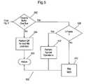
- FIG. 5illustrates a flowchart for performing macroblock level rate control according to the disclosed embodiments.
- FIG. 1depicts a system 100 for transmitting and receiving video signal data according to the disclosed embodiments.
- System 100may be any system or collection of devices that connect over a network to share information.
- Image frames within a video signalis received to be sent over the network.
- the data within the image frameis encoded for transmission using various encoding techniques.
- System 100may be a gaming system where video content is generated in the gaming console and then transmitted to a high-definition digital media renderer, such as a flat-screen television.
- system 100may be a security monitoring system using high definition (HD) video.
- HDhigh definition
- Digital media server 102generates the video content to be transmitted.
- Digital media server 102may be any device, console, camera and the like that captures video data.
- digital media server 102is a gaming console that plays videogames stored on disk or other medium. The content generated from playing the game is displayed for a user to view and interact with in real-time.
- digital media server 102is a computer, video recorder, digital camera, scanner and the like that captures data.
- Uncompressed data signal 104is output from digital media server 102 to encoder 106 .
- Encoder 106may encode or compress signal 104 for transmission within system 100 .
- Encoder 106may use lossy compression techniques to encode signal 104 . The strength of such techniques may change based on the complexity of the data within signal 104 .
- Encoder 106includes slice partitioner 134 , which is disclosed in greater detail below.
- Encoder 106outputs compressed signal 108 to buffer 110 .
- Buffer 110stores data from signal 108 until it can be transmitted through system 100 . If the network bit rate does not allow transmission of signal 108 , then buffer 110 holds the data until such time it can be transmitted by transceiver 114 .
- Buffer 110may have a buffer size value.
- the buffer size value used by the rate control to achieve its targets (latency and bit rate)will be directly related to the maximum transmission latency admitted.
- Buffer 110outputs signal 112 to transceiver 114 .
- Transceiver 114transmits signal 116 over network 118 .
- network 118may be a wireless network for a location where a router receives signal 116 from digital media server 102 and forwards it to digital media renderer 132 for display.
- network 118may be a network of computers receiving signal 116 from a remote camera showing real-time video.
- Transceiver 120receives signal 116 and outputs signal 122 to buffer 124 .
- Buffer 124may have a buffer size value similar to buffer 110 .
- Signal 126streams from buffer 110 to decoder 128 .
- Decoder 128decodes or decompresses signal 126 to generate uncompressed signal 130 .
- Uncompressed signal 130preferably is a high quality copy of uncompressed signal 104 , which slight variations due to the coding process.
- Digital media renderer 132receives uncompressed signal 130 and displays the video data content to the user.
- Digital media renderer 132may be a high-definition television having display resolutions of 1,280 ⁇ 720 pixels (720p) or 1,920 ⁇ 1,080 pixels (1080i/1080p).
- the amount of data encoded and decoded within system 100may be complex due to the demands place on it by digital media server 102 and digital media renderer 132 .
- System 100is subject to various constraints and parameters.
- System 100may transmit over network 118 at a constant bit rate. This bit rate remains the same over time, but, however, may change under certain circumstances.
- a delay or integration timemay occur as buffer 110 fills up, which causes latency within system 100 as data is sent over network 118 .
- FIG. 2Adepicts a graph 200 showing encoding, transmission and decoding times within the system according to the disclosed embodiments.
- Graph 200includes time line 202 that shows an encoding time 204 , a transmission time 206 and a decoding time 208 .
- Encoding time 204may represent the time for a minimum decodable unit to be encoded or compressed by encoder 106 plus the time of the number of video lines needed before start the coding process.
- the minimum decodable unit for the disclosed embodimentsmay be one slice. After this time, encoder 106 can start to transmit this first slice. Traditional schemes wait up to 1 frame before start encoding and start transmitting the bit stream after the entire frame is encoded. This may include 2 frames of encoding time. System 100 minimizes the encoding time by minimizing the wait before starting the encoding, and making smaller the minimum decodable unit.
- Encoding time 204preferably is less than or equal to the time lapse for a minimum decodable unit. For example, if the minimum decodable unit is a frame and the length of time for frame 210 is 1/60 th of a second, then encoding time 204 is less than that within system 100 .
- Transmission time 206represents the time to transmit data over network 118 .
- Transmission time 206also is less than or equal to a time period for needed to send a buffer size number of bits over the network at the expected capacity (equal or lower than the bit rate configured for the rate control).
- Decoding time 208represents the time for a minimum decodable unit of video data to be decoding or uncompress to reconstruct the video signal. Decoding time 208 also is less than or equal to the time period for the minimum decodable unit. If the minimum decodable unit is a frame, this time will be less than 1 frame.
- FIG. 2Ashows how the latency is reduced to a level that moves the frames through system 100 well within the limits needed for real-time video rendering.
- FIG. 2Bdepicts a graph 220 showing bit rate fluctuation within the system over time according to the disclosed embodiments.
- Graph 220shows time line 222 , and video data bit rate line 224 .
- Video data bit rate line 224varies as time line 222 extends.
- Video data bit rate line 224varies as the complexity of the video encoding varies. For example, video data bit rate line 224 rises as complexity increases.
- FIG. 2Balso includes buffer 226 that stores the video data.
- Buffer 226may correspond to buffers 110 and 124 of FIG. 1 . As shown, all of the data for video data bit rate line 224 fits within buffer 226 . Video data bit rate line 224 does not exceed the limits of buffer 226 , no matter how much line 224 varies. Buffer 226 also may have a buffer size. The buffer size may depend on the expected minimum transmission latency, less than one frame according to the disclosed embodiments. This size assures that latency is minimized.
- Valuesmay be set within system 100 to fit the relationships shown in FIGS. 2A and 2B .
- a constant bit rate for network 118may set a specific maximum bit rate value for transmitting and receiving video content. In other words, a value for the necessary bits to encode a frame of video content is determined.
- the frame bits value and the expected latencymay set the buffer size of buffer 226 . For example, if the bit rate is 1000 bits, and if the expected size for a frame and the expected transmission latency is half a frame, then the buffer size will be 500 bits. The amount of data stored in buffer 226 (or buffers 110 and 124 ) may not exceed this value. Thus, any delay or latency within system 100 is about equal or less than the time of the frame ( 1/60 th of a second if frame rate of incoming video is 60 frames per second), as shown in FIG. 2A .
- FIG. 3depicts a video frame 300 having rate control blocks 310 according to the disclosed embodiments.
- every video frame 300has the same number of bits.
- the bit rate for video frame 300may increase if the picture is very busy and requires complex encoding to capture all the action.
- Video frame 300may be comprised of pixels that are grouped to form macroblocks 302 .
- Each macroblock 302includes two or more pixels.
- macroblock 302is 16 pixels by 16 pixels.
- Macroblocks 302are encoded by encoder 106 and sent to decoder 128 using a compression scheme, or other algorithms.
- Information sentmay include the address of the macroblock within video frame 300 , luminance information, chrominance or color information, a compression level value and motion vector information.
- video frame 300may be partitioned into a plurality of macroblocks 302 .
- all of macroblocks 302 of video frame 300are encoded, buffered, and then sent through network 118 .
- the disclosed embodimentspartitions video frame 300 into rate control blocks 310 and uses these rate control blocks as the basis for encoding, transmitting and decoding video data.
- Rate control blocks 310also may be known as sub-frames. Rate control blocks 310 may be used as the basic unit for bit allocation in system 100 , and include a plurality of macroblocks 302 . Preferably, the number of macroblocks 302 in each rate control block 310 is between 5 and 15. Rate control block 310 may include one or more slices of frame 300 .
- the number of macroblockswill depend on the maximum transmission latency expected or required.
- the bigger the size of rate control block 310the higher the minimum latency achievable. Note that the opposite also works, the higher the latency required, the smaller the rate control block required.
- rate control blocks 310may have a target bit rate that corresponds with the duration of a rate control block 310 .
- the target bit rate for rate control blocks 310should be lower than that for video frame 300 as there is much less information to encode. This feature keeps the bit rate fluctuation well below a buffer size for a single video frame 300 .
- Buffer 110includes a buffer size at least equal to a rate control block 310 .
- Encoder 106may forward each rate control block 310 after the last macroblock 302 within it is encoded.
- Decoder 128may start the decoding process of each rate control block 310 independently.
- the bit ratesmay fluctuate between rate control blocks 310 to accommodate “busy” parts of video frame 300 , but never higher than the configured bit rate for the rate control.
- FIG. 4depicts a flowchart 400 for controlling the bit rate within video transmission encoder 106 using rate control blocks 310 according to the disclosed embodiments.
- Step 402executes by determining the frame level initial settings for a video frame 300 . These settings may include the number of bits per frame, the number of macroblocks 302 per frame, the number of macroblocks 302 on a rate control block 310 , the targeted bit rate and the like.
- Step 404executes by generating rate control blocks 310 within video frame 300 .
- video frame 300may include several rate control blocks 310 comprising macroblocks 302 .
- Step 406executes by selecting a rate control block 310 for encoding and transmission. For example, referring to video frame 300 , the top rate control block 310 may be selected initially and so on until the bottom rate control block 310 is encoded.
- Step 408executes by determining the rate control block initial setting. A target bit rate is selected, and a buffer corresponding to the duration of the rate control block 310 is set.
- Encoder 106may allocate a number of bits based on the size of the selected rate control block 310 . Based on the setting, step 410 executes by performing macroblock level rate control using the target bit rate based on the size of rate control blocks 310 . Step 410 is disclosed in greater detail by FIG. 5 .
- Step 412executes by encoding one of macroblocks 302 within rate control block 310 .
- Step 414executes by determining whether the encoded macroblock 302 is the last macroblock in rate control block 310 . If no, then flowchart 400 goes back to step 410 to encode the remaining macroblocks 302 . If yes, then step 416 executes by performing virtual buffer management. Encoded data within buffer 110 is forwarded to transceiver 114 for transmission through network 118 . Because buffer 110 corresponds to the size of rate control block 310 , data from an upper rate control block 310 is not delayed while encoding subsequent rate control blocks 310 .
- Step 418executes by determining whether the last macroblock 302 within video frame 300 is encoded. If no, then flowchart 400 returns to step 406 to select the next rate control block 310 . If yes, then all of video frame 300 has been encoded and a new video frame should be received. Thus, flowchart 400 returns to step 402 .
- FIG. 5depicts a flowchart 500 for performing macroblock level rate control according to the disclosed embodiments.
- Flowchart 500further discloses step 410 of FIG. 4 .
- the disclosed embodimentsmay use estimated and predicted encoding values for macroblocks 302 . These processes “predict” the values for a macroblock 310 during the encoding to reduce encoding time. Such predictions, however, do risk producing an erroneous estimation. This error may be especially likely to occur in a busy video frame with much movement and change from the previous frame.
- encoder 106may predict that the values for macroblock 302 within rate control block 310 are the same for the blue backgrounds.
- An errormay occur when encoder 106 predicts that macroblock 302 has the values for a blue sky when it has the beginning data for an airplane flying in the macroblock.
- the airplanemay be white so that macroblock 302 has values different from the ones for a blue sky, but yet encoder 106 used the predicted values anyway. Such as error may result in a high bit rate to handle the complex change in values.
- the disclosed embodiments shown by FIG. 5may perform some operations to prevent buffer overflow and the resulting latency.
- One such operationmay be to avoid approaching the buffer size limit for a rate control block 310 . Space should be left within buffer 110 to handle any sudden spikes in the bit rate due to complex variations. Despite the space, however, buffer overflow still may occur and needs to be handled accordingly.
- Step 502executes by determining whether the current bit rate for a selected rate control block 310 is close to buffer overflow. If no, then step 504 executes by performing a compression level determination for the next macroblock prediction. Using the compression level results, the disclosed embodiments may predict a similar macroblock 302 to the one it is encoding on a previously encoded video frame 300 . Step 506 executes by returning to flowchart 400 .
- step 508executes by determining whether macroblock 302 is within an entire spatial predicted frame (intra-frame, or I-frame) or entire temporal predicted frame (inter-frame) video setting. If no, then step 510 executes by skipping the encoding process for the remainder of macroblocks 302 within rate control block 310 . Instead, escape macroblocks may be used. Encoder 106 informs decoder 128 that the current frame is similar to previous frame, and those macroblocks may be used to fill out rate control block 310 . Thus, buffer overflow is avoided as the bit rate does not exceed to capacity of buffer 110 .
- step 512executes by performing special operations on the remaining macroblocks 302 within rate control block 310 .
- encoder 106may not use escape macroblocks as the video data does not relate to previous video frames.
- Intra-frame codingrefers to the fact that the various lossless and lossy compression techniques are performed relative to information that is contained only within the current frame, and not relative to any other frame in the video sequence. In other words, no temporal processing is performed outside of the current picture or frame.
- Step 512removes partially or totally the prediction residue so that minimal information is sent.
- Encoder 106keeps using I-frame macroblocks 302 but the remaining macroblocks 302 will have most of the prediction residue being placed as 0 (zero) to reduce the number of bits being used. The result is that the bit rate is reduced to fit within the allocated bit rate for buffer 110 .
- Flowchart 500then returns to flowchart 400 via step 506 .
Landscapes
- Engineering & Computer Science (AREA)
- Multimedia (AREA)
- Signal Processing (AREA)
- Databases & Information Systems (AREA)
- Compression Or Coding Systems Of Tv Signals (AREA)
Abstract
Description
Claims (6)
Priority Applications (8)
| Application Number | Priority Date | Filing Date | Title |
|---|---|---|---|
| US13/067,051US8831108B2 (en) | 2011-05-04 | 2011-05-04 | Low latency rate control system and method |
| KR1020137032245AKR101809306B1 (en) | 2011-05-04 | 2012-05-04 | Low latency rate control system and method |
| PCT/US2012/036646WO2012151548A1 (en) | 2011-05-04 | 2012-05-04 | Low latency rate control system and method |
| CN201280031677.0ACN103718555B (en) | 2011-05-04 | 2012-05-04 | Low latency rate control system and method |
| JP2014509498AJP2014519246A (en) | 2011-05-04 | 2012-05-04 | Low latency rate control system and method |
| US14/480,469US9445107B2 (en) | 2011-05-04 | 2014-09-08 | Low latency rate control system and method |
| JP2016029840AJP6226490B2 (en) | 2011-05-04 | 2016-02-19 | Low latency rate control system and method |
| JP2017143464AJP2017208849A (en) | 2011-05-04 | 2017-07-25 | Small waiting time rate control system and method |
Applications Claiming Priority (1)
| Application Number | Priority Date | Filing Date | Title |
|---|---|---|---|
| US13/067,051US8831108B2 (en) | 2011-05-04 | 2011-05-04 | Low latency rate control system and method |
Related Child Applications (1)
| Application Number | Title | Priority Date | Filing Date |
|---|---|---|---|
| US14/480,469DivisionUS9445107B2 (en) | 2011-05-04 | 2014-09-08 | Low latency rate control system and method |
Publications (2)
| Publication Number | Publication Date |
|---|---|
| US20120281767A1 US20120281767A1 (en) | 2012-11-08 |
| US8831108B2true US8831108B2 (en) | 2014-09-09 |
Family
ID=47090227
Family Applications (2)
| Application Number | Title | Priority Date | Filing Date |
|---|---|---|---|
| US13/067,051Active2033-03-21US8831108B2 (en) | 2011-05-04 | 2011-05-04 | Low latency rate control system and method |
| US14/480,469Active2031-06-16US9445107B2 (en) | 2011-05-04 | 2014-09-08 | Low latency rate control system and method |
Family Applications After (1)
| Application Number | Title | Priority Date | Filing Date |
|---|---|---|---|
| US14/480,469Active2031-06-16US9445107B2 (en) | 2011-05-04 | 2014-09-08 | Low latency rate control system and method |
Country Status (5)
| Country | Link |
|---|---|
| US (2) | US8831108B2 (en) |
| JP (3) | JP2014519246A (en) |
| KR (1) | KR101809306B1 (en) |
| CN (1) | CN103718555B (en) |
| WO (1) | WO2012151548A1 (en) |
Cited By (1)
| Publication number | Priority date | Publication date | Assignee | Title |
|---|---|---|---|---|
| US10003811B2 (en) | 2015-09-01 | 2018-06-19 | Microsoft Technology Licensing, Llc | Parallel processing of a video frame |
Families Citing this family (21)
| Publication number | Priority date | Publication date | Assignee | Title |
|---|---|---|---|---|
| US9247312B2 (en) | 2011-01-05 | 2016-01-26 | Sonic Ip, Inc. | Systems and methods for encoding source media in matroska container files for adaptive bitrate streaming using hypertext transfer protocol |
| US9467708B2 (en) | 2011-08-30 | 2016-10-11 | Sonic Ip, Inc. | Selection of resolutions for seamless resolution switching of multimedia content |
| US8818171B2 (en)* | 2011-08-30 | 2014-08-26 | Kourosh Soroushian | Systems and methods for encoding alternative streams of video for playback on playback devices having predetermined display aspect ratios and network connection maximum data rates |
| KR102074148B1 (en) | 2011-08-30 | 2020-03-17 | 엔엘디 엘엘씨 | Systems and methods for encoding and streaming video encoded using a plurality of maximum bitrate levels |
| US8909922B2 (en) | 2011-09-01 | 2014-12-09 | Sonic Ip, Inc. | Systems and methods for playing back alternative streams of protected content protected using common cryptographic information |
| US9514664B2 (en)* | 2012-09-25 | 2016-12-06 | The Boeing Company | Measuring latency in a test system using captured images |
| US9188644B1 (en) | 2012-09-25 | 2015-11-17 | The Boeing Company | Latency measurement system and method |
| US20140187331A1 (en)* | 2012-12-27 | 2014-07-03 | Nvidia Corporation | Latency reduction by sub-frame encoding and transmission |
| US9191457B2 (en) | 2012-12-31 | 2015-11-17 | Sonic Ip, Inc. | Systems, methods, and media for controlling delivery of content |
| US9094737B2 (en) | 2013-05-30 | 2015-07-28 | Sonic Ip, Inc. | Network video streaming with trick play based on separate trick play files |
| US9979970B2 (en)* | 2014-08-08 | 2018-05-22 | Qualcomm Incorporated | System and method for determining buffer fullness for display stream compression |
| CN111031326B (en)* | 2015-04-02 | 2022-02-11 | 株式会社Kt | Method for processing video signal |
| US20170085886A1 (en)* | 2015-09-18 | 2017-03-23 | Qualcomm Incorporated | Variable partition size for block prediction mode for display stream compression (dsc) |
| CN105706448A (en)* | 2015-12-25 | 2016-06-22 | 王晓光 | Decoding method and system for video software |
| CN107241571B (en)* | 2016-03-29 | 2019-11-22 | 杭州海康威视数字技术股份有限公司 | A kind of encapsulation of multimedia file, playback method and device |
| US10148989B2 (en) | 2016-06-15 | 2018-12-04 | Divx, Llc | Systems and methods for encoding video content |
| CN108696771B (en)* | 2017-04-11 | 2021-03-09 | 苏州谦问万答吧教育科技有限公司 | Video playing method and device |
| US10404565B2 (en)* | 2017-12-13 | 2019-09-03 | Ford Global Technologies, Llc | Simulation latency indication |
| CN110248205B (en)* | 2018-09-03 | 2023-03-24 | 浙江大华技术股份有限公司 | Method and device for packing video recording data |
| JP7465073B2 (en) | 2019-10-28 | 2024-04-10 | キヤノン株式会社 | Image encoding device, control method and program thereof |
| CN114245178A (en)* | 2021-12-20 | 2022-03-25 | 未来电视有限公司 | A method, apparatus, device and storage medium for transmitting video |
Citations (14)
| Publication number | Priority date | Publication date | Assignee | Title |
|---|---|---|---|---|
| US5815604A (en)* | 1995-05-18 | 1998-09-29 | U.S. Philips Corporation | Interactive image manipulation |
| US6055330A (en)* | 1996-10-09 | 2000-04-25 | The Trustees Of Columbia University In The City Of New York | Methods and apparatus for performing digital image and video segmentation and compression using 3-D depth information |
| US20020034246A1 (en)* | 2000-08-04 | 2002-03-21 | Kohji Yamada | Method and apparatus for image signal encoding |
| US20070031050A1 (en)* | 2005-07-25 | 2007-02-08 | Samsung Electronics Co., Ltd. | Method and apparatus for bit rate control for image encoding |
| US20070147512A1 (en)* | 2000-04-18 | 2007-06-28 | Ati International Srl | Method and apparatus for rate control for constant-bit-rate-finite-buffer-size video encoder |
| US20080260062A1 (en)* | 2007-04-17 | 2008-10-23 | Sharp Laboratories Of America, Inc. | Method and system for optimized reference signal downlink transmission in a wireless communication system |
| US20090279611A1 (en) | 2008-04-29 | 2009-11-12 | John Gao | Video edge filtering |
| US20090310672A1 (en)* | 2008-06-13 | 2009-12-17 | W&W Communications, Inc. | Method and System for Rate Control in a Video Encoder |
| US20100080292A1 (en)* | 2006-12-12 | 2010-04-01 | Coulombe Stephane | Video Rate Control for Video Coding Standards |
| US20100091836A1 (en)* | 2008-10-14 | 2010-04-15 | Nvidia Corporation | On-the-spot deblocker in a decoding pipeline |
| US20100166060A1 (en)* | 2008-12-31 | 2010-07-01 | Texas Instruments Incorporated | Video transcoder rate control |
| US20100290419A1 (en)* | 2008-01-05 | 2010-11-18 | Panasonic Corporation | Control channel signaling using code points for indicating the scheduling mode |
| US7929603B2 (en)* | 2006-03-24 | 2011-04-19 | Hewlett-Packard Development Company L.P. | System and method for accurate rate control for video compression |
| US20110122942A1 (en)* | 2009-11-20 | 2011-05-26 | Texas Instruments Incorporated | Techniques for perceptual encoding of video frames |
Family Cites Families (14)
| Publication number | Priority date | Publication date | Assignee | Title |
|---|---|---|---|---|
| JP2002218477A (en)* | 2000-11-20 | 2002-08-02 | Matsushita Electric Ind Co Ltd | Video encoding method, video encoding device, and video relay device |
| TWI226198B (en)* | 2003-08-08 | 2005-01-01 | Lite On It Corp | Method of buffer management in video encoder |
| CN1977516B (en)* | 2004-05-13 | 2010-12-01 | 高通股份有限公司 | Method for transmitting data in wireless communication system and wireless communication device |
| JP5281793B2 (en)* | 2004-07-07 | 2013-09-04 | トムソン ライセンシング | Fast channel switching in digital video broadcast systems via DSL using redundant video streams |
| KR100612871B1 (en)* | 2004-11-11 | 2006-08-14 | 삼성전자주식회사 | Dynamic capacitance compensation device and method of liquid crystal display |
| JP5053097B2 (en)* | 2004-11-22 | 2012-10-17 | トムソン リサーチ ファンディング コーポレイション | Method and apparatus for channel switching in DSL system |
| CN100459717C (en)* | 2005-04-20 | 2009-02-04 | 华为技术有限公司 | Error elimination of compressed video transmission based on H.264 |
| JP2007300455A (en)* | 2006-05-01 | 2007-11-15 | Victor Co Of Japan Ltd | Arithmetic encoding apparatus, and context table initialization method in arithmetic encoding apparatus |
| US7643560B2 (en)* | 2006-10-23 | 2010-01-05 | Vidyo, Inc. | System and method for scalable video coding using telescopic mode flags |
| KR101345295B1 (en)* | 2007-06-11 | 2013-12-27 | 삼성전자주식회사 | Rate control method and apparatus for intra-only video sequence coding |
| CN101217615B (en)* | 2007-12-27 | 2011-04-06 | 北京中星微电子有限公司 | Method and device for controlling bit rate of compressed image |
| JP2009302776A (en)* | 2008-06-11 | 2009-12-24 | Canon Inc | Image encoding device, control method thereof, and computer program |
| JP5072893B2 (en)* | 2009-03-25 | 2012-11-14 | 株式会社東芝 | Image encoding method and image decoding method |
| US20120114034A1 (en)* | 2010-11-08 | 2012-05-10 | Mediatek Inc. | Method and Apparatus of Delta Quantization Parameter Processing for High Efficiency Video Coding |
- 2011
- 2011-05-04USUS13/067,051patent/US8831108B2/enactiveActive
- 2012
- 2012-05-04WOPCT/US2012/036646patent/WO2012151548A1/enactiveApplication Filing
- 2012-05-04CNCN201280031677.0Apatent/CN103718555B/enactiveActive
- 2012-05-04KRKR1020137032245Apatent/KR101809306B1/enactiveActive
- 2012-05-04JPJP2014509498Apatent/JP2014519246A/enactivePending
- 2014
- 2014-09-08USUS14/480,469patent/US9445107B2/enactiveActive
- 2016
- 2016-02-19JPJP2016029840Apatent/JP6226490B2/enactiveActive
- 2017
- 2017-07-25JPJP2017143464Apatent/JP2017208849A/ennot_activeAbandoned
Patent Citations (14)
| Publication number | Priority date | Publication date | Assignee | Title |
|---|---|---|---|---|
| US5815604A (en)* | 1995-05-18 | 1998-09-29 | U.S. Philips Corporation | Interactive image manipulation |
| US6055330A (en)* | 1996-10-09 | 2000-04-25 | The Trustees Of Columbia University In The City Of New York | Methods and apparatus for performing digital image and video segmentation and compression using 3-D depth information |
| US20070147512A1 (en)* | 2000-04-18 | 2007-06-28 | Ati International Srl | Method and apparatus for rate control for constant-bit-rate-finite-buffer-size video encoder |
| US20020034246A1 (en)* | 2000-08-04 | 2002-03-21 | Kohji Yamada | Method and apparatus for image signal encoding |
| US20070031050A1 (en)* | 2005-07-25 | 2007-02-08 | Samsung Electronics Co., Ltd. | Method and apparatus for bit rate control for image encoding |
| US7929603B2 (en)* | 2006-03-24 | 2011-04-19 | Hewlett-Packard Development Company L.P. | System and method for accurate rate control for video compression |
| US20100080292A1 (en)* | 2006-12-12 | 2010-04-01 | Coulombe Stephane | Video Rate Control for Video Coding Standards |
| US20080260062A1 (en)* | 2007-04-17 | 2008-10-23 | Sharp Laboratories Of America, Inc. | Method and system for optimized reference signal downlink transmission in a wireless communication system |
| US20100290419A1 (en)* | 2008-01-05 | 2010-11-18 | Panasonic Corporation | Control channel signaling using code points for indicating the scheduling mode |
| US20090279611A1 (en) | 2008-04-29 | 2009-11-12 | John Gao | Video edge filtering |
| US20090310672A1 (en)* | 2008-06-13 | 2009-12-17 | W&W Communications, Inc. | Method and System for Rate Control in a Video Encoder |
| US20100091836A1 (en)* | 2008-10-14 | 2010-04-15 | Nvidia Corporation | On-the-spot deblocker in a decoding pipeline |
| US20100166060A1 (en)* | 2008-12-31 | 2010-07-01 | Texas Instruments Incorporated | Video transcoder rate control |
| US20110122942A1 (en)* | 2009-11-20 | 2011-05-26 | Texas Instruments Incorporated | Techniques for perceptual encoding of video frames |
Non-Patent Citations (1)
| Title |
|---|
| International Search Report and Written Opinion, issued to International Patent Application No. PCT/US12/36646, Aug. 6, 2012, 8 pgs. |
Cited By (1)
| Publication number | Priority date | Publication date | Assignee | Title |
|---|---|---|---|---|
| US10003811B2 (en) | 2015-09-01 | 2018-06-19 | Microsoft Technology Licensing, Llc | Parallel processing of a video frame |
Also Published As
| Publication number | Publication date |
|---|---|
| US9445107B2 (en) | 2016-09-13 |
| JP2014519246A (en) | 2014-08-07 |
| WO2012151548A1 (en) | 2012-11-08 |
| US20140376640A1 (en) | 2014-12-25 |
| JP2016119708A (en) | 2016-06-30 |
| JP2017208849A (en) | 2017-11-24 |
| JP6226490B2 (en) | 2017-11-08 |
| KR20140027393A (en) | 2014-03-06 |
| CN103718555B (en) | 2017-02-01 |
| CN103718555A (en) | 2014-04-09 |
| US20120281767A1 (en) | 2012-11-08 |
| KR101809306B1 (en) | 2017-12-14 |
Similar Documents
| Publication | Publication Date | Title |
|---|---|---|
| US8831108B2 (en) | Low latency rate control system and method | |
| US10999583B2 (en) | Scalability of multi-directional video streaming | |
| US9288497B2 (en) | Advanced video coding to multiview video coding transcoder | |
| US10009628B2 (en) | Tuning video compression for high frame rate and variable frame rate capture | |
| JP6463041B2 (en) | Image processing apparatus, image processing method, and program | |
| US20120281756A1 (en) | Complexity change detection for video transmission system | |
| JP2015171114A (en) | Moving image encoder | |
| US9226003B2 (en) | Method for transmitting video signals from an application on a server over an IP network to a client device | |
| US20120281757A1 (en) | Scene change detection for video transmission system | |
| US20150131715A1 (en) | Image transmission apparatus, image transmission method, and recording medium | |
| JP6089846B2 (en) | Video distribution system, decoder, and video distribution method | |
| JP5784823B2 (en) | On-demand intra-refresh for end-to-end coded video transmission systems | |
| US12101489B2 (en) | Supporting view direction based random access of bitstream | |
| US20160360230A1 (en) | Video coding techniques for high quality coding of low motion content | |
| US8095955B2 (en) | Methods and systems for improving network response during channel change | |
| CN101682755B (en) | Method and apparatus for encoding/decoding an image by partitioning the image | |
| CN114827668B (en) | Video gear selection method, device and equipment based on decoding capability | |
| EP4102836A1 (en) | Processing video using masking windows | |
| GB2499485A (en) | System for providing trick play operating modes for video streams at the request of a client device. | |
| HK1191485B (en) | Low latency rate control system and method | |
| HK1191485A (en) | Low latency rate control system and method | |
| JP4462559B2 (en) | Trick playback content creation method and device, trick playback compressed video data transmission method and device, and trick playback content creation program | |
| EP2845383A1 (en) | Mechanism for facilitating cost-efficient and low-latency encoding of video streams | |
| US20240214583A1 (en) | Video surveillance system having a load distribution module | |
| CN104702970A (en) | Video data synchronization method, device and system |
Legal Events
| Date | Code | Title | Description |
|---|---|---|---|
| AS | Assignment | Owner name:CAVIUM, INC., CALIFORNIA Free format text:ASSIGNMENT OF ASSIGNORS INTEREST;ASSIGNORS:DUENAS, ALBERTO;IZQUIERDO, FRANCISCO RONCERO;GARCIA, GORKA;REEL/FRAME:026625/0680 Effective date:20110707 | |
| STCF | Information on status: patent grant | Free format text:PATENTED CASE | |
| AS | Assignment | Owner name:JPMORGAN CHASE BANK, N.A., AS COLLATERAL AGENT, ILLINOIS Free format text:SECURITY AGREEMENT;ASSIGNORS:CAVIUM, INC.;CAVIUM NETWORKS LLC;REEL/FRAME:039715/0449 Effective date:20160816 Owner name:JPMORGAN CHASE BANK, N.A., AS COLLATERAL AGENT, IL Free format text:SECURITY AGREEMENT;ASSIGNORS:CAVIUM, INC.;CAVIUM NETWORKS LLC;REEL/FRAME:039715/0449 Effective date:20160816 | |
| MAFP | Maintenance fee payment | Free format text:PAYMENT OF MAINTENANCE FEE, 4TH YEAR, LARGE ENTITY (ORIGINAL EVENT CODE: M1551) Year of fee payment:4 | |
| AS | Assignment | Owner name:CAVIUM, INC, CALIFORNIA Free format text:RELEASE BY SECURED PARTY;ASSIGNOR:JP MORGAN CHASE BANK, N.A., AS COLLATERAL AGENT;REEL/FRAME:046496/0001 Effective date:20180706 Owner name:QLOGIC CORPORATION, CALIFORNIA Free format text:RELEASE BY SECURED PARTY;ASSIGNOR:JP MORGAN CHASE BANK, N.A., AS COLLATERAL AGENT;REEL/FRAME:046496/0001 Effective date:20180706 Owner name:CAVIUM NETWORKS LLC, CALIFORNIA Free format text:RELEASE BY SECURED PARTY;ASSIGNOR:JP MORGAN CHASE BANK, N.A., AS COLLATERAL AGENT;REEL/FRAME:046496/0001 Effective date:20180706 | |
| AS | Assignment | Owner name:CAVIUM, LLC, CALIFORNIA Free format text:CHANGE OF NAME;ASSIGNOR:CAVIUM, INC.;REEL/FRAME:049367/0717 Effective date:20180924 | |
| AS | Assignment | Owner name:CAVIUM INTERNATIONAL, CAYMAN ISLANDS Free format text:ASSIGNMENT OF ASSIGNORS INTEREST;ASSIGNOR:CAVIUM, LLC;REEL/FRAME:051948/0807 Effective date:20191231 | |
| AS | Assignment | Owner name:MARVELL ASIA PTE, LTD., SINGAPORE Free format text:ASSIGNMENT OF ASSIGNORS INTEREST;ASSIGNOR:CAVIUM INTERNATIONAL;REEL/FRAME:053179/0320 Effective date:20191231 | |
| MAFP | Maintenance fee payment | Free format text:PAYMENT OF MAINTENANCE FEE, 8TH YEAR, LARGE ENTITY (ORIGINAL EVENT CODE: M1552); ENTITY STATUS OF PATENT OWNER: LARGE ENTITY Year of fee payment:8 |