US8830854B2 - System and method for managing parallel processing of network packets in a wireless access device - Google Patents
System and method for managing parallel processing of network packets in a wireless access deviceDownload PDFInfo
- Publication number
- US8830854B2 US8830854B2US13/331,367US201113331367AUS8830854B2US 8830854 B2US8830854 B2US 8830854B2US 201113331367 AUS201113331367 AUS 201113331367AUS 8830854 B2US8830854 B2US 8830854B2
- Authority
- US
- United States
- Prior art keywords
- transceiver
- bound
- processing unit
- processing
- event
- Prior art date
- Legal status (The legal status is an assumption and is not a legal conclusion. Google has not performed a legal analysis and makes no representation as to the accuracy of the status listed.)
- Active, expires
Links
- 238000012545processingMethods0.000titleclaimsabstractdescription379
- 238000000034methodMethods0.000titleclaimsdescription62
- 230000004044responseEffects0.000claimsabstractdescription31
- 238000004148unit processMethods0.000claimsabstractdescription9
- 230000027455bindingEffects0.000claimsdescription55
- 238000009739bindingMethods0.000claimsdescription55
- 238000004891communicationMethods0.000claimsdescription28
- 238000012423maintenanceMethods0.000claimsdescription5
- 230000003287optical effectEffects0.000description5
- 238000010586diagramMethods0.000description4
- 238000003491arrayMethods0.000description3
- 230000006870functionEffects0.000description3
- 238000004590computer programMethods0.000description2
- 238000011144upstream manufacturingMethods0.000description2
- 230000006399behaviorEffects0.000description1
- 230000000694effectsEffects0.000description1
- 238000012986modificationMethods0.000description1
- 230000004048modificationEffects0.000description1
- 239000004065semiconductorSubstances0.000description1
Images


Classifications
- H—ELECTRICITY
- H04—ELECTRIC COMMUNICATION TECHNIQUE
- H04L—TRANSMISSION OF DIGITAL INFORMATION, e.g. TELEGRAPHIC COMMUNICATION
- H04L47/00—Traffic control in data switching networks
- H04L47/70—Admission control; Resource allocation
- H—ELECTRICITY
- H04—ELECTRIC COMMUNICATION TECHNIQUE
- H04L—TRANSMISSION OF DIGITAL INFORMATION, e.g. TELEGRAPHIC COMMUNICATION
- H04L49/00—Packet switching elements
- H04L49/90—Buffering arrangements
- H04L49/9021—Plurality of buffers per packet
- H—ELECTRICITY
- H04—ELECTRIC COMMUNICATION TECHNIQUE
- H04L—TRANSMISSION OF DIGITAL INFORMATION, e.g. TELEGRAPHIC COMMUNICATION
- H04L47/00—Traffic control in data switching networks
- H04L47/70—Admission control; Resource allocation
- H04L47/82—Miscellaneous aspects
- H04L47/824—Applicable to portable or mobile terminals
Definitions
- Hardware acceleratorsdistribute packets to as many processing units as possible and schedules processing of the packets to ensure the serial processing of packets from the same conversational flows and schedule processing of the packets in a manner that maintains the packet order.
- hardware acceleratorsmay be designed to work closely with Ethernet adapters and may be designed to process Ethernet packets in particular.
- the hardware acceleratorsare seemingly incompatible with packets transmitted over a wireless network that uses a wireless protocol, e.g., the IEEE 802.11 standard.
- wireless protocole.g., the IEEE 802.11 standard.
- wireless packet processinge.g., various encoding and encryption schemes, continually changing standards, etc.
- a method of managing parallel processing of network packetsis provided.
- a wireless access devicethat includes multiple transceivers and multiple processing units receives network packets.
- the transceiver associated with a received network packetis determined. Whether the transceiver associated with the received network packet is bound to one of the processing units is also determined.
- the received network packetis assigned to the processing unit the transceiver is bound to.
- the transceiveris bound to a processing unit such that the processing unit processes network packets associated with the transceiver while the transceiver is bound to the processing unit, and the received network packet is assigned to the processing unit the transceiver is bound to.
- a system for managing parallel processing of network packetsis also provided.
- a wireless access devicethat includes multiple transceivers and multiple processing units receives network packets.
- a media access controllerdetermines which transceiver a received network packet is associated with.
- a tagging moduledetermines whether the transceiver associated with the received network packet is bound to one of the processing units.
- a schedulerassigns the received packet to the processing unit the transceiver is bound to.
- the tagging moduleIn response to a determination that the transceiver is not bound, the tagging module binds the transceiver to a processing unit such that the processing unit processes network packets associated with the transceiver while the transceiver is bound to the processing unit, and the scheduler assigns the received network packet to the processing unit the transceiver is bound to.
- a method of managing parallel processing of events occurring at a wireless access deviceincludes multiple transceivers and multiple processing units.
- the transceiver an event is associated withis determined. Whether the transceiver associated with the event is bound to one of the processing units is also determined. In response to a determination that the transceiver is bound, the event is assigned to the processing unit the transceiver is bound to. In response to a determination that the transceiver is not bound, the transceiver is bound to one of the processing units, and the event is assigned to the processing unit the transceiver is bound to.
- FIG. 1is an example of an implementation of a system for maximizing parallel processing in a wireless array.
- FIG. 2is a packet flow diagram for an example of an implementation of a system for maximizing parallel processing in a wireless array.
- FIG. 3Ais a representation of a processing queue in a first stage of operation.
- FIG. 3Bis a representation of the processing queue of FIG. 3A in a second stage of operation.
- FIG. 4Ais a representation of a binding table in a first stage of operation.
- FIG. 4Bis a representation of the binding table of FIG. 4A in a second stage of operation.
- FIG. 5is a flowchart of example method steps for maximizing parallel processing in a wireless array.
- a wireless arrayis a wireless access device having multiple transceivers.
- Wireless arraysmay include, for example, four, eight, twelve, or sixteen wireless transceivers. Each transceiver of the wireless array may operate on a different channel.
- the transceivers of the wireless arraymay be used to provide clients with wireless access to a network by exchanging wireless communications with the clients.
- the wireless access devicemay be described as being in signal communication with the client.
- the wireless array 102includes a wireless interface 104 having four transceivers 106 a , 106 b , 106 c , and 106 d (T 1 -T 4 ).
- the transceivers 106 of the wireless array 102may be, for example, radios for exchanging wireless communications with a client 108 a , 108 b , 108 c , 108 d , 108 e .
- a clientmay be in signal communication with a particular transceiver, and transceivers may be in signal communication with multiple clients concurrently as illustrated by way of example in FIG. 1 .
- client 108 ais in signal communication with transceiver 106 a ; client 108 b is in signal communication with transceiver 106 b ; client 108 c with transceiver 106 c ; and client 108 d and client 108 e are in signal communication with transceiver 106 d .
- the transceivers 106are also in signal communication with a media access controller 110 (MAC), which manages the communications between the transceivers and the clients 108 in signal communication with the wireless array 102 .
- MACmedia access controller 110
- a client 108 in signal communication with the wireless array 102refers to a client that exchanges communication signals with the wireless array or simply transmits communication signals to the wireless array.
- a client 108 in signal communication with the wireless array 102transmits communication signals within range of a wireless array such that the wireless array can hear (e.g., receive the broadcast from) the client.
- a client 108 that is in signal communication with a wireless array 102is connected to the wireless array if the client has been authenticated via, for example, a password.
- a client 108may be in signal communication with the wireless array 102 but not connected to the wireless array if the client has not been authenticated.
- a client 108 in signal communication with but not connected to the wireless array 102may be referred to as rogue client. Rogue clients may also include other wireless access devices.
- the clientWhen a client 108 connects to the wireless array 102 , the client associates with a particular transceiver 106 at the wireless array. Data then flows back and forth between the client 108 and the wireless array 102 on the channel for the transceiver 106 the client is associated with.
- the wireless array 102may maintain a global association table 112 at a data store 114 that indicates the particular transceiver 106 a client 108 connected to the wireless array is associated with.
- the wireless array 102may also include a processing module 116 having multiple processing units 118 a , 118 b , 118 c , and 118 d (P 1 -P 4 ) as shown by way of example in FIG. 1 .
- the processing module 116 for a wireless array 102may include, for example, two, four, or eight processing units 118 .
- the wireless array 102may additionally include a wired network interface 120 (e.g., an Ethernet interface) that allows a client 108 to be in signal communication with a wired network 122 (e.g., an Ethernet network). As discussed further below, the wireless array 102 may also maintain a binding table 125 that indicates which processing units 118 are busy and which processing units idle and available to do work (e.g., process packets).
- a wired network interface 120e.g., an Ethernet interface
- a wired network 122e.g., an Ethernet network
- the wireless array 102may also maintain a binding table 125 that indicates which processing units 118 are busy and which processing units idle and available to do work (e.g., process packets).
- the processing module 116may perform various types of work in response to events that occur at the wireless array 102 .
- One example of an eventis the receipt of a packet at a transceiver 106 or the wired network interface 120 .
- the processing module 116may process the packet.
- Other examples of eventsinclude the generation of an interrupt by a transceiver 106 that requires attention and access of a processing unit 118 to, e.g., configure the transceiver.
- the processing module 116may perform work in response to additional or alternative events that occur at the transceiver.
- the wireless arrayalso includes a tagging module 123 .
- the tagging module 123tags received packets with a tag value such that packets with the same tag value are processed by the same processing unit.
- the tagging module 123may include a hardware accelerator 124 as shown by way of example in FIG. 1 .
- the hardware accelerator 124in this example, includes: a processing queue 126 that contains work entries to process; and a scheduler 128 that assigns packets to processing units 118 for processing.
- the hardware accelerator 124in the example shown, is configured to maximize parallel processing of both packets received from both the wired network interface 120 and the wireless interface 104 .
- a hardware accelerator 124 suitable to maximize parallel processing in the wireless array 102may be available from Cavium, Inc. of San Jose, Calif., as part of the OCTEONTM family of Multi-Core MIPS64 processors including, but not limited to the CN38XX/CN36XX family of Multi-Core MIPS64 Based SoC Processors as model numbers CN3630, CN3830, CN3840, CN3850, and CN3860. Furthermore, an implementation that uses a hardware accelerator 124 from Cavium, Inc. may set the tag type for the work entry in the processing queue 126 to “ATOMIC” in order to serialize processing of packets, or other events, associated with the same tag value.
- the system 100maximizes parallel processing of network packets by dynamically binding one or more transceivers 106 to one of the processing units 118 in the processing module 116 . Binding a transceiver 106 to a processing unit 118 assigns that transceiver to the processing unit such that the processing unit processes packets associated with the transceiver while the processing unit is assigned to the transceiver. When a transceiver 106 is bound to a processing unit 118 , no other processing unit will process packets associated with the assigned transceiver 106 . In other words, when a transceiver 106 is bound to a processing unit 118 , no other processing unit will process packets that originate from or are destined to that transceiver.
- binding the transceiver to a processing unit 118ensures that packets associated with the conversational flow are processed sequentially. In this way, the system 100 serializes the processing of packets in the same conversational flow. Binding a transceiver 106 to a particular processing unit 118 also ensures that multiple processing units do not simultaneously access the same transceiver or data structures associated with the same transceiver. Note that the binding of transceivers to processing units is many-to-one: many transceivers may be bound to a single processing unit. Once a transceiver is bound to a processing unit, however, no other processing unit will process packets associated with the bound transceiver. Accordingly the system 100 advantageously reduces the need for locking and synchronization thereby improving parallel processing of the packets.
- the system 100determines if there are any outstanding events associated with the transceiver. If there are outstanding events associated with the transceiver 106 remain, then the system 100 maintains the binding of the transceiver to the processing unit 118 until the outstanding events are processed. If there are no outstanding events associated with the transceiver 106 , then the system 100 unbinds the transceiver from the processing unit. Once unbound from the processing unit 118 , the transceiver 106 is free to be subsequently bound and assigned to another processing unit in response to the occurrence of events associated with that transceiver.
- the system 100ensures that the packets are processed sequentially while advantageously allowing any processing unit 118 to process events associated with a particular transceiver if there are no events associated with that transceiver currently being processed or queued for processing by another processing unit.
- the system 100groups together communications associated with a particular transceiver 106 . If multiple endpoints are associated with a particular transceiver 106 , for example, then the system 100 groups together the communications between that transceiver 106 and those endpoints for processing packets associated with those endpoints.
- the tagging module 123tags received packets with a unique identifier.
- the tagging module 123tags packets associated with the same transceiver with the same unique identifier, i.e., tag value. Note that packets from different conversational flows may be associated with the same transceiver 106 if the respective endpoints for those conversational flows are each associated with that transceiver.
- the tagging module 123tags packets associated with the same transceiver with the same unique identifier.
- the hardware accelerator 124may be configured to determine a unique identifier for a received packet and tag the received packet with the unique identifier.
- the tagging modulemay include a software module (not shown) that determines the unique identifier for the received packet and tags the received packet with the unique identifier.
- the unique identifiermay be a 5-tuple that combines: the source port number; the source IP address (Internet Protocol); the destination port number; the destination IP address; and a protocol identifier, which may be hashed to a tag value.
- the hardware accelerator 124may set the hashed tag value as the unique identifier for the received packet.
- the unique identifiermay be information identifying the transceiver 106 associated with the packet.
- the information identifying the transceiver 106 associated with the packetmay be the transceiver number.
- the hardware accelerator 124includes a tagging component (not shown) that may be referred to as the packet input processor (PIP), and the tagging module 123 may use the tagging component of the hardware accelerator to tag received packets with the unique identifier.
- the PIPmay compute the 5-tuple hash, insert the tag value into a work entry, and insert the work entry into the work queue.
- the tagging module 123may include a software module (not shown) that inserts a tag value based on a transceiver number into a work entry and inserts the work entry into the work queue. It will be understood that the PIP may be configured to insert a tag value based on a transceiver number as well.
- the hardware accelerator 124may add a respective work entry to the processing queue 126 for each packet to be processed.
- Work entries in the processing queue 126may include or be associated with the respective tag values for the packets to be processed.
- a work entry in the processing queue 126may also indicate which transceiver 106 the packet is associated with.
- the media access controller 110may determine which transceiver 106 the packet is associated with based on, for example, the origin or destination of the packet.
- the media access controllermay perform a lookup in the association table 112 to determine which transceiver 106 the packet is associated with based on the destination of the packet, and the transceiver number (e.g., T 1 , T 2 , T 3 , T 4 , etc.) may be included in or associated with the processing queue work entry for the packet to be processed.
- the transceiver numbere.g., T 1 , T 2 , T 3 , T 4 , etc.
- the processing module 116may perform work in response to various types of events that occur at the wireless array, e.g., transceiver interrupts, transceiver configurations, etc. Accordingly the hardware accelerator may also add entries to the processing queue 126 associated with these events as the events occur. Events may include, for example, receipt of a packet at a transceiver 106 of the wireless array 102 , i.e., a received network packet event; configuration of the transceiver, i.e., a transceiver configuration event; and maintenance of the transceiver, i.e., a transceiver maintenance event. In order to maximize parallel processing of responses to these events, the system 100 may bind a transceiver 106 to a processing unit 118 while the processing unit processes a response to the event.
- the system 100processes the packet associated with the work entry.
- the scheduler 128determines which processing unit 118 should process the packet.
- the system 100dynamically assigns packets associated with a particular transceiver 106 to a processing unit 118 for processing. Also mentioned above, the system 100 dynamically binds a transceiver 106 to a particular processing unit 118 , which ensures that, while the transceiver is bound to the processing unit, packets from that transceiver are processed by the same processing unit.
- the scheduler 128may first determine if the transceiver 106 associated with the packet is already bound to a particular processing unit. If the transceiver 106 associated with the packet is currently bound to a particular processing unit 118 , the scheduler 128 assigns the packet to that processing unit associated with the transceiver. If the transceiver 106 associated with the packet is not already bound to a particular processing unit 118 , the scheduler 128 identifies a processing unit 118 to bind the transceiver 106 to.
- that scheduler 128may determine if a processing unit is idle (i.e., not currently performing work) and thus available to process the packet. If a processing unit 118 is available to process the packet, the scheduler 128 binds the transceiver 106 to the available processing unit by updating the binding table 125 with information identifying the processing unit the transceiver is bound to. In some example implementations, if a processing unit 118 is not currently available, the scheduler 128 may wait until a processing unit becomes available to bind the transceiver 106 to a processing unit. Additionally or alternatively the scheduler 128 may bind multiple transceivers 106 to a single processing unit 118 as discussed above.
- the scheduler 128may, for example, advantageously bind multiple transceivers 106 to a single processing unit 118 where work performed for one transceiver takes a relatively long amount of time but requires minimal intervention from the processing unit thus allowing the processing unit to perform work for another transceiver in the meantime. Furthermore the particular behavior of the scheduler in this manner may be user-configurable.
- the hardware accelerator 124may remove the work entry from the processing queue 126 corresponding to the processed packet.
- the hardware accelerator 124unbinds that transceiver 106 from the processing unit 118 by updating the binding table 125 to indicate the transceiver is available to be subsequently bound to another processing unit.
- a processing unit 118in this example, is bound to a particular transceiver 106 as long as the processing queue 126 includes entries corresponding to packets associated with that transceiver.
- Thismay be determined, for example, by determining whether the processing queue includes entries that include or are associated with the transceiver number (e.g., T 1 , T 2 , T 3 , T 4 , etc.) for the transceiver 106 .
- the transceiver numbere.g., T 1 , T 2 , T 3 , T 4 , etc.
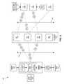
- FIG. 2a block diagram of packet flow in an example of an implementation of a system 100 for maximizing parallel processing in a wireless array is shown.
- FIG. 2illustrates the flow of packets A 1 - 3 , B 1 - 2 , and C 1 - 2 through the system 100 from the wired network interface 122 to the transceivers 106 .
- the system 100processes packets of three conversational flows from three different clients: a flow from client 130 a (packets A 1 , A 2 , and A 3 ); a flow from client 130 b (packets B 1 and B 2 ); and a flow from client 130 c (packets C 1 and C 2 ).
- FIG. 1illustrates the flow of packets A 1 - 3 , B 1 - 2 , and C 1 - 2 through the system 100 from the wired network interface 122 to the transceivers 106 .
- the system 100processes packets of three conversational flows from three different clients: a flow from client 130 a (
- client 130 a and client 130 bare connected to and associated with transceiver 106 a
- client 130 cis connected to and associated with transceiver 106 b
- the system 100exchanges wireless communications with client 130 a and client 130 b via transceiver 106 a
- the systemexchanges wireless communications with client 130 c via transceiver 106 b
- a third transceiver 106 cis not associated with any conversational flow.
- the bulleted lines 132 in FIG. 2represents a break in time between the receipt and processing of packets A 1 , A 2 , B 1 , C 1 , and C 2 and the receipt and processing of packets A 3 and B 2 .
- the system 100receives and processes packets A 1 , A 2 , B 1 , C 1 , and C 2 before the system receives and processes packets A 3 and B 2 .
- the system 100first receives a flow of packets A 1 , A 2 , and B 2 associated with transceiver T 1 and a flow of packets C 1 and C 2 associated with transceiver T 2 .
- the packetsare received at the wired network interface 122 .
- the hardware accelerator 124may assign a tag value to these packets using, for example, the transceiver number associated with the packets, e.g., T 1 or T 2 .
- packets A 1 ,A 2 , and B 1would receive the same unique tag value indicating the packets are associated with transceiver T 1
- packets C 1 and C 2would receive a unique tag value indicating the packet is associated with transceiver T 2 .
- an example processing queue 126 a and an example binding table 125 aare shown respectively.
- the hardware accelerator 124may create respective entries in the processing queue 126 a for each of the received packets A 1 , A 2 , B 1 , C 1 , and C 2 .
- the media access controller 110may perform a lookup in the association table 112 to determine which respective transceivers 106 the clients 130 are associated with, and the hardware accelerator 124 may update the entries 134 a in the processing queue 126 a to include information 136 a that indicates the respective transceivers 106 the packets are associated with.
- the processing queuemay also include a work entry 135 a for an event associated with transceiver T 3 , e.g., configuring transceiver T 3 .
- the scheduler 128may then assign the packets to a processing unit 118 for processing and update the respective entries in the processing queue to include information 138 a that indicates the processing unit 118 the packet is assigned to. Since packet A 1 is at the front of the processing queue 126 a , in this example, the scheduler 128 determines if transceiver 106 a (T 1 ) is bound to a processing unit 118 by consulting the binding table. Since transceiver 106 a (T 1 ) is not yet bound to a processing unit 118 , in this example, the scheduler 128 may bind transceiver T 1 to processing unit 118 a as shown by way of example in the binding table 125 a of FIG.
- processing unit 118 aP 1
- T 1transceiver T 1
- the scheduler 128may update the work entry in the processing queue 126 a with information 138 a that indicates which processing unit 118 a packet is assigned to for processing.
- the scheduler 128may then assign other packets to processing units 118 in a similar fashion.
- the next work entry in the processing queue 126 ais packet A 2 .
- packet A 2is also associated with transceiver 106 a (T 1 ), and the scheduler 128 may determine that transceiver T 1 is currently bound to processing unit 118 a (P 1 ) by performing a lookup in the binding table 125 a . Accordingly, the scheduler 128 may assign packet A 2 to processing unit 118 a (P 1 ) as well as shown by way of example in the processing queue 126 a of FIG. 3A .
- Packet B 1is likewise associated with transceiver 106 a (T 1 ), and the scheduler 128 may also assign packet B 1 to processing unit 118 a (P 1 ) after performing a lookup in the binding table 136 a and determining that transceiver T 1 is bound to processing unit P 1 .
- Packet C 1in this example, is associated with transceiver 106 b (T 2 ). Accordingly, the scheduler 128 may determine that transceiver 106 b (T 2 ) is not bound to a particular processing unit 118 after performing a lookup in the binding table 125 a .
- the scheduler 128may bind transceiver 106 b (T 2 ) to an idle processing unit 118 , e.g., processing unit 118 c (P 3 ) as shown by way of example in the binding table 125 a of FIG. 4A .
- the scheduler 128may then assign packet C 1 to processing unit 118 c (P 3 ) as shown by way of example in the processing queue 126 a of FIG. 3A .
- Packet C 2is destined for the same endpoint as packet C 1 , i.e., client 130 c , and is thus also associated with transceiver 106 b (T 2 ) as seen in the example processing queue 126 a of FIG. 3A .
- the scheduler 128may determine that transceiver 106 b (T 2 ) is bound to processing unit 118 c (P 3 ) and assign packet C 2 to processing unit P 3 as a result.
- the schedulermay bind transceiver T 3 to an idle processing unit, e.g., processing unit 118 d (P 4 ), or a processing unit already performing work, e.g., processing unit 118 c (P 3 ) as shown by way of example in the binding table 125 a of FIG. 4A .
- an idle processing unite.g., processing unit 118 d (P 4 )
- a processing unit already performing worke.g., processing unit 118 c (P 3 ) as shown by way of example in the binding table 125 a of FIG. 4A .
- the scheduler 128may remove the processing queue work entry from the processing queue 126 .
- the system 100does not unbind a transceiver 106 from a processing unit 118 until the processing queue 126 contains no work entries associated with that transceiver. Accordingly when the scheduler 128 removes a work entry 134 associated with a transceiver, the scheduler, in this example, may then determine if the processing queue 126 contains any remaining work entries associated with the transceiver 106 .
- the processing queue 126still contains entries 134 a respectively corresponding to packet A 2 and packet B 1 , which are each associated with transceiver 106 a (T 1 ).
- the scheduler 128will not yet unbind transceiver 106 a (T 1 ) from processing unit 118 a (P 1 ).
- the processing queue 126in this example, only contains entries 134 a corresponding to packets C 1 and C 2 , which are associated with transceiver T 2 . Because the processing queue 126 a does not contain any more entries associated with transceiver T 1 , in this example, the hardware accelerator 124 may unbind transceiver 106 a (T 1 ) from processing unit 118 a (P 1 ).
- the system 100may receive packets A 3 and B 2 some time after receipt and processing of packets A 1 , A 2 , B 1 , C 1 , and C 2 as indicated by the bulleted lines 132 .
- an updated processing queue 126 b and an updated binding table 125 bare respectively shown.
- the processing queue 126 bstill includes a work entry 135 b showing the binding of transceiver 106 c (T 3 ) to processing unit 118 b (P 2 ) indicating, in this example, that processing unit P 2 is still performing work for transceiver T 3 .
- the hardware accelerator 124may tag packets A 3 and B 2 , and the scheduler 128 may create respective work entries 134 b in the processing queue 126 b for packets A 3 and B 2 as discussed above.
- the processing queue entries 134 bmay likewise include information 136 b indicating which transceivers the packets are associated with, e.g., the transceiver number, and information 138 b indicating which processing unit 118 the transceivers are assigned to.
- each of the processing units 118 a , 118 b , 118 c , and 118 dmay be idle and available to process packets A 3 and B 2 .
- the scheduler 128may bind transceiver 106 a (T 1 ) to one of the available processing units 118 , e.g., processing unit 118 b (P 2 ) as shown by way of example in the binding table 125 b of FIG. 4B and assign packets A 3 and B 2 to processing unit 118 b (P 2 ) as shown by way of example in the processing queue 126 b FIG. 3B .
- the scheduler 128may bind a transceiver 106 to a processing unit 118 that is already performing work for another transceiver as discussed above.
- the system 100advantageously maximizes parallel processing of packets while maintaining serialized processing of packets from the same conversational flow.
- the system 100may maximize parallel processing of packets from both the wireless interface 104 (“upstream”) and from the wired network interface 120 (“downstream”). It will be understood that, typically, the wireless array 102 will process more downstream traffic than upstream traffic.
- a flowchart 140 of example method steps for maximizing parallel processing in a wireless array 102is also shown in FIG. 5 .
- the system 100may receive one or more packets to process (step 142 ).
- the hardware accelerator 124determines a unique tag value for each of the packets based on the transceiver 106 the packet is associated with as discussed above (step 144 ).
- the hardware accelerator 124may then tag packets associated with the same transceiver 106 with the same unique tag value.
- the scheduler 128in this example, then creates respective work entries in the processing queue 126 for the packets (step 146 ).
- the processing queuemay include work entries for other types of work associated with the transceiver, e.g., handling interrupts, configuration, etc.
- the media access controller 110determines which transceivers 106 are respectively associated with the packets (step 148 ).
- the scheduler 128may update the work entries 134 of the processing queue 126 to identify the respective transceivers 106 the packets are associated with.
- the scheduler 128selects the work entry 134 at the front of the processing queue 126 , e.g., a packet processing work entry (step 150 ).
- the hardware accelerator 124determines the status of the transceiver 106 associated with the packet to process, i.e., whether the transceiver is bound to a processing unit 118 (step 152 ).
- the hardware accelerator 124may determine the status of the transceiver 106 by, for example, consulting a binding table 125 that includes information indicating transceiver-processing unit bindings. If the transceiver 106 is bound to a processing unit 118 , the processing unit processes all packets associated with the transceiver 106 bound to the processing unit.
- the scheduler 128assigns the packet to the processing unit bound to the transceiver for processing (step 156 ). If the hardware accelerator 124 determines the transceiver 106 is not bound to a processing unit 118 (step 154 ), then the scheduler 128 identifies a processing unit to bind the transceiver to in order to perform the work, e.g., process the packet (step 158 ).
- the scheduler 128determines that all processing units 118 are currently bound to other transceivers 106 (step 160 ), i.e., if an idle processing unit is unavailable, then the scheduler may wait for a processing unit to become available. If the scheduler 128 , in this example, determines that a processing unit 118 is available to process the packet (step 160 ), then the hardware accelerator 124 binds the transceiver 106 to the available processing unit (step 162 ). As discussed above, however, the scheduler 124 may also bind a transceiver to a processing unit 118 that is already bound to and performing work for another transceiver. The hardware accelerator 124 may bind the transceiver 106 to an available processing unit 118 by, for example, updating the binding table 125 to indicate the transceiver is bound to the processing unit.
- the assigned processing unitmay process the packet (step 164 ).
- the scheduler 128may remove the work entry from the processing queue 126 (step 166 ).
- the scheduler 128may determine whether the processing queue 126 includes work entries associated with transceivers 106 presently bound to processing units 118 (step 168 ). As discussed above, the scheduler 128 does not unbind a transceiver 106 from a processing unit 118 if the processing queue 126 includes work entries 134 that are associated with transceivers bound to processing units.
- the system 100ensures the same processing unit 118 processes packets associated with the same transceiver 106 . If the processing queue 126 includes work entries associated with bound transceivers 106 (step 170 ), then the next processing queue entry 134 in the processing queue may be selected for processing (step 150 ) and steps 152 - 168 may be repeated. If the processing queue 126 does not include processing queue work entries 134 associated with a bound transceiver 106 (step 170 ), then the hardware accelerator 124 may unbind the transceiver from the processing unit 118 by, e.g., updating the binding table 125 (step 172 ).
- the transceiver 106When the transceiver 106 is unbound from a processing unit 118 , the transceiver becomes available to be subsequently bound to another processing unit. In this way, the system 100 maximizes parallel processing of packets in a wireless array. It will be understood that additional or alternative components of the system 100 may carry out the example method steps set forth above.
- FIGS. 1-5may be performed by hardware, software, or a combination of hardware and software on one or more electronic or digitally-controlled devices.
- the softwaremay reside in a software memory (not shown) in a suitable electronic processing component or system such as, for example, one or more of the functional systems, devices, components, modules, or sub-modules schematically depicted in FIGS. 1-2 . 3 A-B, and 4 A-B.
- the software memorymay include an ordered listing of executable instructions for implementing logical functions (that is, “logic” that may be implemented in digital form such as digital circuitry or source code, or in analog form such as analog source such as an analog electrical, sound, or video signal).
- the instructionsmay be executed within a processing module, which includes, for example, one or more microprocessors, general purpose processors, combinations of processors, digital signal processors (DSPs), field programmable gate arrays (FPGAs), or application-specific integrated circuits (ASICs).
- DSPsdigital signal processors
- FPGAsfield programmable gate arrays
- ASICsapplication-specific integrated circuits
- the schematic diagramsdescribe a logical division of functions having physical (hardware and/or software) implementations that are not limited by architecture or the physical layout of the functions.
- the example systems described in this applicationmay be implemented in a variety of configurations and operate as hardware/software components in a single hardware/software unit, or in separate hardware/software units.
- the executable instructionsmay be implemented as a computer program product having instructions stored therein which, when executed by a processing module of an electronic system (e.g., a system for maximizing parallel processing in a wireless array in FIG. 1 ), direct the electronic system to carry out the instructions.
- the computer program productmay be selectively embodied in any non-transitory computer-readable storage medium for use by or in connection with an instruction execution system, apparatus, or device, such as a electronic computer-based system, processor-containing system, or other system that may selectively fetch the instructions from the instruction execution system, apparatus, or device and execute the instructions.
- computer-readable storage mediumis any non-transitory means that may store the program for use by or in connection with the instruction execution system, apparatus, or device.
- the non-transitory computer-readable storage mediummay selectively be, for example, an electronic, magnetic, optical, electromagnetic, infrared, or semiconductor system, apparatus, or device.
- a non-exhaustive list of more specific examples of non-transitory computer readable mediainclude: an electrical connection having one or more wires (electronic); a portable computer diskette (magnetic); a random access, i.e., volatile, memory (electronic); a read-only memory (electronic); an erasable programmable read only memory such as, for example, Flash memory (electronic); a compact disc memory such as, for example, CD-ROM, CD-R, CD-RW (optical); and digital versatile disc memory, i.e., DVD (optical).
- non-transitory computer-readable storage mediummay even be paper or another suitable medium upon which the program is printed, as the program can be electronically captured via, for instance, optical scanning of the paper or other medium, then compiled, interpreted, or otherwise processed in a suitable manner if necessary, and then stored in a computer memory or machine memory.
- the term “in signal communication” as used in this documentmeans that two or more systems, devices, components, modules, or sub-modules are capable of communicating with each other via signals that travel over some type of signal path.
- the signalsmay be communication, power, data, or energy signals, which may communicate information, power, or energy from a first system, device, component, module, or sub-module to a second system, device, component, module, or sub-module along a signal path between the first and second system, device, component, module, or sub-module.
- the signal pathsmay include physical, electrical, magnetic, electromagnetic, electrochemical, optical, wired, or wireless connections.
- the signal pathsmay also include additional systems, devices, components, modules, or sub-modules between the first and second system, device, component, module, or sub-module.
Landscapes
- Engineering & Computer Science (AREA)
- Computer Networks & Wireless Communication (AREA)
- Signal Processing (AREA)
- Mobile Radio Communication Systems (AREA)
Abstract
Description
Claims (36)
Priority Applications (1)
| Application Number | Priority Date | Filing Date | Title |
|---|---|---|---|
| US13/331,367US8830854B2 (en) | 2011-07-28 | 2011-12-20 | System and method for managing parallel processing of network packets in a wireless access device |
Applications Claiming Priority (2)
| Application Number | Priority Date | Filing Date | Title |
|---|---|---|---|
| US201161512689P | 2011-07-28 | 2011-07-28 | |
| US13/331,367US8830854B2 (en) | 2011-07-28 | 2011-12-20 | System and method for managing parallel processing of network packets in a wireless access device |
Publications (2)
| Publication Number | Publication Date |
|---|---|
| US20130028181A1 US20130028181A1 (en) | 2013-01-31 |
| US8830854B2true US8830854B2 (en) | 2014-09-09 |
Family
ID=47597173
Family Applications (1)
| Application Number | Title | Priority Date | Filing Date |
|---|---|---|---|
| US13/331,367Active2033-03-10US8830854B2 (en) | 2011-07-28 | 2011-12-20 | System and method for managing parallel processing of network packets in a wireless access device |
Country Status (1)
| Country | Link |
|---|---|
| US (1) | US8830854B2 (en) |
Families Citing this family (3)
| Publication number | Priority date | Publication date | Assignee | Title |
|---|---|---|---|---|
| US10857100B2 (en)* | 2014-04-01 | 2020-12-08 | Tdl Innovations Llc | Methods and compositions for administering an active agent to the pleura of a patient |
| US20170196528A1 (en)* | 2014-05-23 | 2017-07-13 | Vatech Co., Ltd. | Medical image photographing apparatus and medical image correction method using depth camera |
| US20180082501A1 (en)* | 2016-09-16 | 2018-03-22 | Ford Global Technologies, Llc | Integrated on-board data collection |
Citations (87)
| Publication number | Priority date | Publication date | Assignee | Title |
|---|---|---|---|---|
| US4042935A (en) | 1974-08-01 | 1977-08-16 | Hughes Aircraft Company | Wideband multiplexing antenna feed employing cavity backed wing dipoles |
| US4649391A (en) | 1984-02-01 | 1987-03-10 | Hughes Aircraft Company | Monopulse cavity-backed multipole antenna system |
| US4726050A (en) | 1986-02-18 | 1988-02-16 | Motorola, Inc. | Scanning receiver allocation method and apparatus for cellular radiotelephone systems |
| US5389941A (en) | 1992-02-28 | 1995-02-14 | Hughes Aircraft Company | Data link antenna system |
| US5592480A (en)* | 1995-03-13 | 1997-01-07 | Carney; Ronald R. | Wideband wireless basestation making use of time division multiple-access bus having selectable number of time slots and frame synchronization to support different modulation standards |
| US5952983A (en) | 1997-05-14 | 1999-09-14 | Andrew Corporation | High isolation dual polarized antenna system using dipole radiating elements |
| US6140972A (en) | 1998-12-11 | 2000-10-31 | Telecommunications Research Laboratories | Multiport antenna |
| US6157811A (en) | 1994-01-11 | 2000-12-05 | Ericsson Inc. | Cellular/satellite communications system with improved frequency re-use |
| US6161024A (en)* | 1998-10-15 | 2000-12-12 | Airnet Communications Corporations | Redundant broadband multi-carrier base station for wireless communications using omni-directional overlay on a tri-sectored wireless system |
| US20010033600A1 (en) | 2000-02-28 | 2001-10-25 | Golden Bridge Technology Inc. | Sectorized smart antenna system and method |
| US6326926B1 (en) | 2000-05-18 | 2001-12-04 | Telxon Corporation | Method of operating a wireless and a short-range wireless connection in the same frequency |
| US6329954B1 (en) | 2000-04-14 | 2001-12-11 | Receptec L.L.C. | Dual-antenna system for single-frequency band |
| US20020039082A1 (en) | 2000-02-01 | 2002-04-04 | Cordell Fox | Passive anti-jamming antenna system |
| US6370386B1 (en)* | 1998-10-15 | 2002-04-09 | Airnet Communications Corporation | Method for dynamic allocation of wireless base station DSP resources with integrated rate converters |
| US6374078B1 (en) | 1998-04-17 | 2002-04-16 | Direct Wireless Corporation | Wireless communication system with multiple external communication links |
| US6452565B1 (en) | 1999-10-29 | 2002-09-17 | Antenova Limited | Steerable-beam multiple-feed dielectric resonator antenna |
| US20020163933A1 (en) | 2000-11-03 | 2002-11-07 | Mathilde Benveniste | Tiered contention multiple access (TCMA): a method for priority-based shared channel access |
| US20020186678A1 (en) | 2001-06-08 | 2002-12-12 | Motorola,Inc | Method and apparatus for resolving half duplex message collisions |
| US20030040319A1 (en) | 2001-04-13 | 2003-02-27 | Hansen Christopher J. | Dynamic frequency selection in a wireless communication network |
| US6539204B1 (en) | 2000-09-29 | 2003-03-25 | Mobilian Corporation | Analog active cancellation of a wireless coupled transmit signal |
| US6544173B2 (en) | 2000-05-19 | 2003-04-08 | Welch Allyn Protocol, Inc. | Patient monitoring system |
| US6606059B1 (en) | 2000-08-28 | 2003-08-12 | Intel Corporation | Antenna for nomadic wireless modems |
| US6646611B2 (en) | 2001-03-29 | 2003-11-11 | Alcatel | Multiband telecommunication antenna |
| US20030210193A1 (en) | 2002-05-13 | 2003-11-13 | Rossman Court Emerson | Low Profile Two-Antenna Assembly Having a Ring Antenna and a Concentrically-Located Monopole Antenna |
| US20040001429A1 (en) | 2002-06-27 | 2004-01-01 | Jianglei Ma | Dual-mode shared OFDM methods/transmitters, receivers and systems |
| US20040005227A1 (en) | 2002-06-21 | 2004-01-08 | Hugues Cremer | Process for assembly of an electric pump, and a vibration damper for such a pump |
| US20040052227A1 (en) | 2002-09-16 | 2004-03-18 | Andrew Corporation | Multi-band wireless access point |
| US20040066326A1 (en) | 2002-10-02 | 2004-04-08 | Guenther Knapp | Electromagnetic coupler system |
| US20040102222A1 (en) | 2002-11-21 | 2004-05-27 | Efstratios Skafidas | Multiple access wireless communications architecture |
| US20040105412A1 (en) | 2002-12-02 | 2004-06-03 | Docomo Communications Laboratories Usa, Inc. | Point coordinator control passing scheme using a scheduling information parameter set for an IEEE 802.11 wireless local area network |
| US20040143681A1 (en) | 2002-12-09 | 2004-07-22 | Mathilde Benveniste | Distributed architecture for deploying multiple wireless local-area network |
| US20040157551A1 (en) | 2002-06-21 | 2004-08-12 | Tantivy Communications, Inc | Repeater for extending range of time division duplex communication system |
| US20040196813A1 (en) | 2003-04-07 | 2004-10-07 | Yoram Ofek | Multi-sector antenna apparatus |
| US20040203347A1 (en) | 2002-03-12 | 2004-10-14 | Hung Nguyen | Selecting a set of antennas for use in a wireless communication system |
| US20040224637A1 (en) | 2002-11-04 | 2004-11-11 | Silva Marcus Da | Directed wireless communication |
| US20040242274A1 (en) | 2003-05-30 | 2004-12-02 | Corbett Christopher J. | Using directional antennas to mitigate the effects of interference in wireless networks |
| US20040240424A1 (en) | 2003-03-06 | 2004-12-02 | Mo-Han Fong | Reverse link enhancement for CDMA 2000 release D |
| US20040259563A1 (en) | 2002-11-21 | 2004-12-23 | Morton John Jack | Method and apparatus for sector channelization and polarization for reduced interference in wireless networks |
| US20040259558A1 (en) | 2002-11-21 | 2004-12-23 | Efstratios Skafidas | Method and apparatus for coverage and throughput enhancement in a wireless communication system |
| US20050020299A1 (en) | 2003-06-23 | 2005-01-27 | Quorum Systems, Inc. | Time interleaved multiple standard single radio system apparatus and method |
| US20050025254A1 (en) | 2003-07-31 | 2005-02-03 | Awad Yassin Aden | Adaptive modulation and coding |
| US20050035919A1 (en) | 2003-08-15 | 2005-02-17 | Fan Yang | Multi-band printed dipole antenna |
| US20050058111A1 (en) | 2003-09-15 | 2005-03-17 | Pai-Fu Hung | WLAN device having smart antenna system |
| US20050058097A1 (en) | 2003-09-17 | 2005-03-17 | Samsung Electronics Co., Ltd. | System and method for dynamic channel allocation in a communication system using an orthogonal frequency division multiple access network |
| US6888504B2 (en) | 2002-02-01 | 2005-05-03 | Ipr Licensing, Inc. | Aperiodic array antenna |
| US20050117546A1 (en)* | 2003-12-02 | 2005-06-02 | Marcello Lioy | Method and apparatus for supporting inter-technology handoffs with Mobile IP |
| US6903703B2 (en) | 2003-11-06 | 2005-06-07 | Harris Corporation | Multiband radially distributed phased array antenna with a sloping ground plane and associated methods |
| US6933909B2 (en) | 2003-03-18 | 2005-08-23 | Cisco Technology, Inc. | Multichannel access point with collocated isolated antennas |
| US20050237258A1 (en) | 2002-03-27 | 2005-10-27 | Abramov Oleg Y | Switched multi-beam antenna |
| US20050254470A1 (en) | 2004-05-13 | 2005-11-17 | Haim Yashar | Wireless packet communications system and method |
| US20050255892A1 (en) | 2004-04-28 | 2005-11-17 | Hong Kong Applied Science And Technology Research Institute Co., Ltd. | Systems and methods for wireless network range extension |
| US20060038738A1 (en) | 2004-08-18 | 2006-02-23 | Video54 Technologies, Inc. | Wireless system having multiple antennas and multiple radios |
| US20060098616A1 (en) | 2004-11-05 | 2006-05-11 | Ruckus Wireless, Inc. | Throughput enhancement by acknowledgement suppression |
| US20060109799A1 (en) | 2004-11-25 | 2006-05-25 | Institute For Information Industry | Methods and systems of dynamic channel allocation for access points in wireless networks |
| US7057566B2 (en) | 2004-01-20 | 2006-06-06 | Cisco Technology, Inc. | Flexible multichannel WLAN access point architecture |
| US7103386B2 (en) | 2003-06-19 | 2006-09-05 | Ipr Licensing, Inc. | Antenna steering and hidden node recognition for an access point |
| US7119744B2 (en) | 2004-01-20 | 2006-10-10 | Cisco Technology, Inc. | Configurable antenna for a wireless access point |
| US20060233280A1 (en) | 2005-04-19 | 2006-10-19 | Telefonaktiebolaget L M Ericsson | Selection of channel coding and multidimensional interleaving schemes for improved performance |
| US7193562B2 (en) | 2004-11-22 | 2007-03-20 | Ruckus Wireless, Inc. | Circuit board having a peripheral antenna apparatus with selectable antenna elements |
| US20070066234A1 (en) | 2003-07-03 | 2007-03-22 | Rotani, Inc. | Method and apparatus for high throughput multiple radio sectorized wireless cell |
| US7202824B1 (en) | 2003-10-15 | 2007-04-10 | Cisco Technology, Inc. | Dual hemisphere antenna |
| US20070178927A1 (en) | 2006-01-27 | 2007-08-02 | Fernandez-Corbaton Ivan J | Centralized medium access control algorithm for CDMA reverse link |
| US7253783B2 (en) | 2002-09-17 | 2007-08-07 | Ipr Licensing, Inc. | Low cost multiple pattern antenna for use with multiple receiver systems |
| US20070210974A1 (en) | 2002-09-17 | 2007-09-13 | Chiang Bing A | Low cost multiple pattern antenna for use with multiple receiver systems |
| US7292198B2 (en) | 2004-08-18 | 2007-11-06 | Ruckus Wireless, Inc. | System and method for an omnidirectional planar antenna apparatus with selectable elements |
| US20070293178A1 (en) | 2006-05-23 | 2007-12-20 | Darin Milton | Antenna Control |
| US7358912B1 (en) | 2005-06-24 | 2008-04-15 | Ruckus Wireless, Inc. | Coverage antenna apparatus with selectable horizontal and vertical polarization elements |
| US7362280B2 (en) | 2004-08-18 | 2008-04-22 | Ruckus Wireless, Inc. | System and method for a minimized antenna apparatus with selectable elements |
| US20080137681A1 (en) | 2004-11-05 | 2008-06-12 | Kish William S | Communications throughput with unicast packet transmission alternative |
| US20080221918A1 (en) | 2007-03-07 | 2008-09-11 | Welch Allyn, Inc. | Network performance monitor |
| US20080225814A1 (en) | 2002-07-26 | 2008-09-18 | Broadcom Corporation | Wireless access point service coverage area management |
| US20080268778A1 (en) | 2005-03-09 | 2008-10-30 | De La Garrigue Michael | Media Access Controller for Use in a Multi-Sector Access Point Array |
| US20090028095A1 (en) | 2007-07-28 | 2009-01-29 | Kish William S | Wireless Network Throughput Enhancement Through Channel Aware Scheduling |
| US7496070B2 (en) | 2004-06-30 | 2009-02-24 | Symbol Technologies, Inc. | Reconfigureable arrays of wireless access points |
| US7498999B2 (en) | 2004-11-22 | 2009-03-03 | Ruckus Wireless, Inc. | Circuit board having a peripheral antenna apparatus with selectable antenna elements and selectable phase shifting |
| US7498996B2 (en) | 2004-08-18 | 2009-03-03 | Ruckus Wireless, Inc. | Antennas with polarization diversity |
| US20090075606A1 (en) | 2005-06-24 | 2009-03-19 | Victor Shtrom | Vertical multiple-input multiple-output wireless antennas |
| US7567213B2 (en) | 2006-05-02 | 2009-07-28 | Accton Technology Corporation | Array structure for the application to wireless switch of WLAN and WMAN |
| US7652632B2 (en) | 2004-08-18 | 2010-01-26 | Ruckus Wireless, Inc. | Multiband omnidirectional planar antenna apparatus with selectable elements |
| US20100053010A1 (en) | 2004-08-18 | 2010-03-04 | Victor Shtrom | Antennas with Polarization Diversity |
| US7696946B2 (en) | 2004-08-18 | 2010-04-13 | Ruckus Wireless, Inc. | Reducing stray capacitance in antenna element switching |
| US20100103065A1 (en) | 2004-08-18 | 2010-04-29 | Victor Shtrom | Dual Polarization Antenna with Increased Wireless Coverage |
| US20100103066A1 (en) | 2004-08-18 | 2010-04-29 | Victor Shtrom | Dual Band Dual Polarization Antenna Array |
| US20100119002A1 (en) | 2008-11-12 | 2010-05-13 | Xirrus, Inc. | Mimo antenna system |
| US20110090878A1 (en)* | 2009-10-16 | 2011-04-21 | Silver Spring Networks, Inc. | Wireless Device With Opportunistic Band Access |
| US8078194B2 (en) | 2007-05-25 | 2011-12-13 | Broadcom Corporation | Position determination using received broadcast signals |
| US8239599B1 (en)* | 2011-06-16 | 2012-08-07 | Hewlett-Packard Development Company, L.P. | System and method for handling data streams |
- 2011
- 2011-12-20USUS13/331,367patent/US8830854B2/enactiveActive
Patent Citations (100)
| Publication number | Priority date | Publication date | Assignee | Title |
|---|---|---|---|---|
| US4042935A (en) | 1974-08-01 | 1977-08-16 | Hughes Aircraft Company | Wideband multiplexing antenna feed employing cavity backed wing dipoles |
| US4649391A (en) | 1984-02-01 | 1987-03-10 | Hughes Aircraft Company | Monopulse cavity-backed multipole antenna system |
| US4726050A (en) | 1986-02-18 | 1988-02-16 | Motorola, Inc. | Scanning receiver allocation method and apparatus for cellular radiotelephone systems |
| US5389941A (en) | 1992-02-28 | 1995-02-14 | Hughes Aircraft Company | Data link antenna system |
| US6157811A (en) | 1994-01-11 | 2000-12-05 | Ericsson Inc. | Cellular/satellite communications system with improved frequency re-use |
| US5592480A (en)* | 1995-03-13 | 1997-01-07 | Carney; Ronald R. | Wideband wireless basestation making use of time division multiple-access bus having selectable number of time slots and frame synchronization to support different modulation standards |
| US5952983A (en) | 1997-05-14 | 1999-09-14 | Andrew Corporation | High isolation dual polarized antenna system using dipole radiating elements |
| US6374078B1 (en) | 1998-04-17 | 2002-04-16 | Direct Wireless Corporation | Wireless communication system with multiple external communication links |
| US6370386B1 (en)* | 1998-10-15 | 2002-04-09 | Airnet Communications Corporation | Method for dynamic allocation of wireless base station DSP resources with integrated rate converters |
| US6161024A (en)* | 1998-10-15 | 2000-12-12 | Airnet Communications Corporations | Redundant broadband multi-carrier base station for wireless communications using omni-directional overlay on a tri-sectored wireless system |
| US6140972A (en) | 1998-12-11 | 2000-10-31 | Telecommunications Research Laboratories | Multiport antenna |
| US6452565B1 (en) | 1999-10-29 | 2002-09-17 | Antenova Limited | Steerable-beam multiple-feed dielectric resonator antenna |
| US20020039082A1 (en) | 2000-02-01 | 2002-04-04 | Cordell Fox | Passive anti-jamming antenna system |
| US20010033600A1 (en) | 2000-02-28 | 2001-10-25 | Golden Bridge Technology Inc. | Sectorized smart antenna system and method |
| US6329954B1 (en) | 2000-04-14 | 2001-12-11 | Receptec L.L.C. | Dual-antenna system for single-frequency band |
| US6326926B1 (en) | 2000-05-18 | 2001-12-04 | Telxon Corporation | Method of operating a wireless and a short-range wireless connection in the same frequency |
| US6544173B2 (en) | 2000-05-19 | 2003-04-08 | Welch Allyn Protocol, Inc. | Patient monitoring system |
| US6606059B1 (en) | 2000-08-28 | 2003-08-12 | Intel Corporation | Antenna for nomadic wireless modems |
| US6539204B1 (en) | 2000-09-29 | 2003-03-25 | Mobilian Corporation | Analog active cancellation of a wireless coupled transmit signal |
| US20020163933A1 (en) | 2000-11-03 | 2002-11-07 | Mathilde Benveniste | Tiered contention multiple access (TCMA): a method for priority-based shared channel access |
| US6646611B2 (en) | 2001-03-29 | 2003-11-11 | Alcatel | Multiband telecommunication antenna |
| US20030040319A1 (en) | 2001-04-13 | 2003-02-27 | Hansen Christopher J. | Dynamic frequency selection in a wireless communication network |
| US20020186678A1 (en) | 2001-06-08 | 2002-12-12 | Motorola,Inc | Method and apparatus for resolving half duplex message collisions |
| US6888504B2 (en) | 2002-02-01 | 2005-05-03 | Ipr Licensing, Inc. | Aperiodic array antenna |
| US20040203347A1 (en) | 2002-03-12 | 2004-10-14 | Hung Nguyen | Selecting a set of antennas for use in a wireless communication system |
| US20050237258A1 (en) | 2002-03-27 | 2005-10-27 | Abramov Oleg Y | Switched multi-beam antenna |
| US20030210193A1 (en) | 2002-05-13 | 2003-11-13 | Rossman Court Emerson | Low Profile Two-Antenna Assembly Having a Ring Antenna and a Concentrically-Located Monopole Antenna |
| US20040005227A1 (en) | 2002-06-21 | 2004-01-08 | Hugues Cremer | Process for assembly of an electric pump, and a vibration damper for such a pump |
| US20040157551A1 (en) | 2002-06-21 | 2004-08-12 | Tantivy Communications, Inc | Repeater for extending range of time division duplex communication system |
| US20040001429A1 (en) | 2002-06-27 | 2004-01-01 | Jianglei Ma | Dual-mode shared OFDM methods/transmitters, receivers and systems |
| US20080225814A1 (en) | 2002-07-26 | 2008-09-18 | Broadcom Corporation | Wireless access point service coverage area management |
| US20040052227A1 (en) | 2002-09-16 | 2004-03-18 | Andrew Corporation | Multi-band wireless access point |
| US20070210974A1 (en) | 2002-09-17 | 2007-09-13 | Chiang Bing A | Low cost multiple pattern antenna for use with multiple receiver systems |
| US7253783B2 (en) | 2002-09-17 | 2007-08-07 | Ipr Licensing, Inc. | Low cost multiple pattern antenna for use with multiple receiver systems |
| US20040066326A1 (en) | 2002-10-02 | 2004-04-08 | Guenther Knapp | Electromagnetic coupler system |
| US20040224637A1 (en) | 2002-11-04 | 2004-11-11 | Silva Marcus Da | Directed wireless communication |
| US20040102222A1 (en) | 2002-11-21 | 2004-05-27 | Efstratios Skafidas | Multiple access wireless communications architecture |
| US20040259563A1 (en) | 2002-11-21 | 2004-12-23 | Morton John Jack | Method and apparatus for sector channelization and polarization for reduced interference in wireless networks |
| US20040259558A1 (en) | 2002-11-21 | 2004-12-23 | Efstratios Skafidas | Method and apparatus for coverage and throughput enhancement in a wireless communication system |
| US20040105412A1 (en) | 2002-12-02 | 2004-06-03 | Docomo Communications Laboratories Usa, Inc. | Point coordinator control passing scheme using a scheduling information parameter set for an IEEE 802.11 wireless local area network |
| US20040143681A1 (en) | 2002-12-09 | 2004-07-22 | Mathilde Benveniste | Distributed architecture for deploying multiple wireless local-area network |
| US20040240424A1 (en) | 2003-03-06 | 2004-12-02 | Mo-Han Fong | Reverse link enhancement for CDMA 2000 release D |
| US6933909B2 (en) | 2003-03-18 | 2005-08-23 | Cisco Technology, Inc. | Multichannel access point with collocated isolated antennas |
| US20040196813A1 (en) | 2003-04-07 | 2004-10-07 | Yoram Ofek | Multi-sector antenna apparatus |
| US20040242274A1 (en) | 2003-05-30 | 2004-12-02 | Corbett Christopher J. | Using directional antennas to mitigate the effects of interference in wireless networks |
| US7103386B2 (en) | 2003-06-19 | 2006-09-05 | Ipr Licensing, Inc. | Antenna steering and hidden node recognition for an access point |
| US20050020299A1 (en) | 2003-06-23 | 2005-01-27 | Quorum Systems, Inc. | Time interleaved multiple standard single radio system apparatus and method |
| US20070066234A1 (en) | 2003-07-03 | 2007-03-22 | Rotani, Inc. | Method and apparatus for high throughput multiple radio sectorized wireless cell |
| US20080274748A1 (en) | 2003-07-03 | 2008-11-06 | Rotani, Inc. | Methods and Apparatus for Channel Assignment |
| US7274944B2 (en) | 2003-07-03 | 2007-09-25 | Rotani, Inc. | Method and apparatus for high throughput multiple radio sectorized wireless cell |
| US20050025254A1 (en) | 2003-07-31 | 2005-02-03 | Awad Yassin Aden | Adaptive modulation and coding |
| US20050035919A1 (en) | 2003-08-15 | 2005-02-17 | Fan Yang | Multi-band printed dipole antenna |
| US20050058111A1 (en) | 2003-09-15 | 2005-03-17 | Pai-Fu Hung | WLAN device having smart antenna system |
| US20050058097A1 (en) | 2003-09-17 | 2005-03-17 | Samsung Electronics Co., Ltd. | System and method for dynamic channel allocation in a communication system using an orthogonal frequency division multiple access network |
| US7202824B1 (en) | 2003-10-15 | 2007-04-10 | Cisco Technology, Inc. | Dual hemisphere antenna |
| US6903703B2 (en) | 2003-11-06 | 2005-06-07 | Harris Corporation | Multiband radially distributed phased array antenna with a sloping ground plane and associated methods |
| US20050117546A1 (en)* | 2003-12-02 | 2005-06-02 | Marcello Lioy | Method and apparatus for supporting inter-technology handoffs with Mobile IP |
| US7119744B2 (en) | 2004-01-20 | 2006-10-10 | Cisco Technology, Inc. | Configurable antenna for a wireless access point |
| US7057566B2 (en) | 2004-01-20 | 2006-06-06 | Cisco Technology, Inc. | Flexible multichannel WLAN access point architecture |
| US20050255892A1 (en) | 2004-04-28 | 2005-11-17 | Hong Kong Applied Science And Technology Research Institute Co., Ltd. | Systems and methods for wireless network range extension |
| US20050254470A1 (en) | 2004-05-13 | 2005-11-17 | Haim Yashar | Wireless packet communications system and method |
| US7496070B2 (en) | 2004-06-30 | 2009-02-24 | Symbol Technologies, Inc. | Reconfigureable arrays of wireless access points |
| US20100053010A1 (en) | 2004-08-18 | 2010-03-04 | Victor Shtrom | Antennas with Polarization Diversity |
| US20060038738A1 (en) | 2004-08-18 | 2006-02-23 | Video54 Technologies, Inc. | Wireless system having multiple antennas and multiple radios |
| US20100103066A1 (en) | 2004-08-18 | 2010-04-29 | Victor Shtrom | Dual Band Dual Polarization Antenna Array |
| US7292198B2 (en) | 2004-08-18 | 2007-11-06 | Ruckus Wireless, Inc. | System and method for an omnidirectional planar antenna apparatus with selectable elements |
| US20100103065A1 (en) | 2004-08-18 | 2010-04-29 | Victor Shtrom | Dual Polarization Antenna with Increased Wireless Coverage |
| US7696946B2 (en) | 2004-08-18 | 2010-04-13 | Ruckus Wireless, Inc. | Reducing stray capacitance in antenna element switching |
| US7362280B2 (en) | 2004-08-18 | 2008-04-22 | Ruckus Wireless, Inc. | System and method for a minimized antenna apparatus with selectable elements |
| US7652632B2 (en) | 2004-08-18 | 2010-01-26 | Ruckus Wireless, Inc. | Multiband omnidirectional planar antenna apparatus with selectable elements |
| US20080136715A1 (en) | 2004-08-18 | 2008-06-12 | Victor Shtrom | Antenna with Selectable Elements for Use in Wireless Communications |
| US7511680B2 (en) | 2004-08-18 | 2009-03-31 | Ruckus Wireless, Inc. | Minimized antenna apparatus with selectable elements |
| US7498996B2 (en) | 2004-08-18 | 2009-03-03 | Ruckus Wireless, Inc. | Antennas with polarization diversity |
| US7505447B2 (en) | 2004-11-05 | 2009-03-17 | Ruckus Wireless, Inc. | Systems and methods for improved data throughput in communications networks |
| US7787436B2 (en) | 2004-11-05 | 2010-08-31 | Ruckus Wireless, Inc. | Communications throughput with multiple physical data rate transmission determinations |
| US20060098616A1 (en) | 2004-11-05 | 2006-05-11 | Ruckus Wireless, Inc. | Throughput enhancement by acknowledgement suppression |
| US20080137681A1 (en) | 2004-11-05 | 2008-06-12 | Kish William S | Communications throughput with unicast packet transmission alternative |
| US7864119B2 (en) | 2004-11-22 | 2011-01-04 | Ruckus Wireless, Inc. | Antenna array |
| US7193562B2 (en) | 2004-11-22 | 2007-03-20 | Ruckus Wireless, Inc. | Circuit board having a peripheral antenna apparatus with selectable antenna elements |
| US7498999B2 (en) | 2004-11-22 | 2009-03-03 | Ruckus Wireless, Inc. | Circuit board having a peripheral antenna apparatus with selectable antenna elements and selectable phase shifting |
| US20100053023A1 (en) | 2004-11-22 | 2010-03-04 | Victor Shtrom | Antenna Array |
| US7525486B2 (en) | 2004-11-22 | 2009-04-28 | Ruckus Wireless, Inc. | Increased wireless coverage patterns |
| US20060109799A1 (en) | 2004-11-25 | 2006-05-25 | Institute For Information Industry | Methods and systems of dynamic channel allocation for access points in wireless networks |
| US20080267151A1 (en) | 2005-03-09 | 2008-10-30 | Abraham Hartenstein | Wireless Local Area Network Antenna Array |
| US20080268778A1 (en) | 2005-03-09 | 2008-10-30 | De La Garrigue Michael | Media Access Controller for Use in a Multi-Sector Access Point Array |
| US20060233280A1 (en) | 2005-04-19 | 2006-10-19 | Telefonaktiebolaget L M Ericsson | Selection of channel coding and multidimensional interleaving schemes for improved performance |
| US7646343B2 (en) | 2005-06-24 | 2010-01-12 | Ruckus Wireless, Inc. | Multiple-input multiple-output wireless antennas |
| US20080291098A1 (en) | 2005-06-24 | 2008-11-27 | William Kish | Coverage antenna apparatus with selectable horizontal and vertical polarization elements |
| US7358912B1 (en) | 2005-06-24 | 2008-04-15 | Ruckus Wireless, Inc. | Coverage antenna apparatus with selectable horizontal and vertical polarization elements |
| US20090075606A1 (en) | 2005-06-24 | 2009-03-19 | Victor Shtrom | Vertical multiple-input multiple-output wireless antennas |
| US7675474B2 (en) | 2005-06-24 | 2010-03-09 | Ruckus Wireless, Inc. | Horizontal multiple-input multiple-output wireless antennas |
| US20070178927A1 (en) | 2006-01-27 | 2007-08-02 | Fernandez-Corbaton Ivan J | Centralized medium access control algorithm for CDMA reverse link |
| US7567213B2 (en) | 2006-05-02 | 2009-07-28 | Accton Technology Corporation | Array structure for the application to wireless switch of WLAN and WMAN |
| US20070293178A1 (en) | 2006-05-23 | 2007-12-20 | Darin Milton | Antenna Control |
| US20080221918A1 (en) | 2007-03-07 | 2008-09-11 | Welch Allyn, Inc. | Network performance monitor |
| US8078194B2 (en) | 2007-05-25 | 2011-12-13 | Broadcom Corporation | Position determination using received broadcast signals |
| US20090028095A1 (en) | 2007-07-28 | 2009-01-29 | Kish William S | Wireless Network Throughput Enhancement Through Channel Aware Scheduling |
| US20100119002A1 (en) | 2008-11-12 | 2010-05-13 | Xirrus, Inc. | Mimo antenna system |
| US20110090878A1 (en)* | 2009-10-16 | 2011-04-21 | Silver Spring Networks, Inc. | Wireless Device With Opportunistic Band Access |
| US8239599B1 (en)* | 2011-06-16 | 2012-08-07 | Hewlett-Packard Development Company, L.P. | System and method for handling data streams |
Also Published As
| Publication number | Publication date |
|---|---|
| US20130028181A1 (en) | 2013-01-31 |
Similar Documents
| Publication | Publication Date | Title |
|---|---|---|
| US10644941B2 (en) | System and method for a software defined protocol network node | |
| CN108363615B (en) | Method for allocating tasks and system for reconfigurable processing system | |
| US7990974B1 (en) | Packet processing on a multi-core processor | |
| US9438447B2 (en) | Flow distribution algorithm for aggregated links in an ethernet switch | |
| US8913613B2 (en) | Method and system for classification and management of inter-blade network traffic in a blade server | |
| CN105075204B (en) | configurable multi-core network processor | |
| US10757076B2 (en) | Enhanced network processing of virtual node data packets | |
| US9396154B2 (en) | Multi-core processor for managing data packets in communication network | |
| CN104468401A (en) | Message processing method and device | |
| US10104006B2 (en) | Bus interface apparatus, router, and bus system including them | |
| CN106330741B (en) | Message transmission method and device | |
| US9164771B2 (en) | Method for thread reduction in a multi-thread packet processor | |
| US8830854B2 (en) | System and method for managing parallel processing of network packets in a wireless access device | |
| US10887234B1 (en) | Programmatic selection of load balancing output amongst forwarding paths | |
| CN105939356A (en) | Virtual firewall dividing method and device | |
| US20170046306A1 (en) | Data processing method, processor, and data processing device | |
| CN110839007B (en) | Cloud network security processing method and device and computer storage medium | |
| CN103281205B (en) | A kind of method of configured port isolation information and the network equipment | |
| US10177935B2 (en) | Data transfer system, data transfer server, data transfer method, and program recording medium | |
| CN108696429B (en) | Apparatus, system, and method for facilitating controller-based multicast signaling | |
| JP2011091711A (en) | Node, method for distributing transmission frame, and program | |
| US8730811B2 (en) | Managing network traffic | |
| US20130283293A1 (en) | System and method for Intelligently distributing a plurality of transactions for parallel processing | |
| US9396302B2 (en) | Global router using graphics processing unit | |
| US12363051B2 (en) | Crossbar multipathing for multicast performance in tiled switches |
Legal Events
| Date | Code | Title | Description |
|---|---|---|---|
| AS | Assignment | Owner name:XIRRUS, INC., CALIFORNIA Free format text:ASSIGNMENT OF ASSIGNORS INTEREST;ASSIGNOR:ROSEN, DAVID B.;REEL/FRAME:027835/0332 Effective date:20120227 | |
| AS | Assignment | Owner name:CARR & FERRELL, LLP, CALIFORNIA Free format text:SECURITY AGREEMENT;ASSIGNOR:XIRRUS, INC.;REEL/FRAME:029923/0752 Effective date:20130208 | |
| AS | Assignment | Owner name:SILICON VALLEY BANK, CALIFORNIA Free format text:SECURITY AGREEMENT;ASSIGNOR:XIRRUS, INC.;REEL/FRAME:029992/0105 Effective date:20120530 | |
| AS | Assignment | Owner name:TRIPLEPOINT CAPITAL LLC, CALIFORNIA Free format text:SECURITY AGREEMENT;ASSIGNOR:XIRRUS, INC.;REEL/FRAME:031867/0745 Effective date:20131220 | |
| AS | Assignment | Owner name:CARR & FERRELL LLP, CALIFORNIA Free format text:SECURITY AGREEMENT;ASSIGNOR:XIRRUS, INC.;REEL/FRAME:032380/0252 Effective date:20131119 | |
| AS | Assignment | Owner name:TRIPLEPOINT VENTURE GROWTH BDC CORP., CALIFORNIA Free format text:ASSIGNMENT OF SECURITY AGREEMENT (REEL 031867, FRAME 0745);ASSIGNOR:TRIPLEPOINT CAPITAL LLC;REEL/FRAME:032410/0338 Effective date:20140305 | |
| AS | Assignment | Owner name:XIRRUS, INC., CALIFORNIA Free format text:RELEASE BY SECURED PARTY;ASSIGNOR:CARR & FERRELL LLP;REEL/FRAME:032794/0290 Effective date:20140422 Owner name:XIRRUS, INC., CALIFORNIA Free format text:RELEASE BY SECURED PARTY;ASSIGNOR:CARR & FERRELL LLP;REEL/FRAME:032794/0265 Effective date:20140422 | |
| STCF | Information on status: patent grant | Free format text:PATENTED CASE | |
| AS | Assignment | Owner name:XIRRUS, INC., CALIFORNIA Free format text:RELEASE OF INTELLECTUAL PROPERTY SECURITY AGREEMENT RECORDED AT REEL 029992/FRAME 0105;ASSIGNOR:SILICON VALLEY BANK;REEL/FRAME:042388/0164 Effective date:20170421 Owner name:XIRRUS, INC., CALIFORNIA Free format text:RELEASE OF SECURITY INTEREST RECORDED AT REEL 031867/FRAME 0745;ASSIGNOR:TRIPLEPOINT VENTURE GROWTH BDC CORP., AS ASSIGNEE OF TRIPLEPOINT CAPITAL LLC;REEL/FRAME:042388/0753 Effective date:20170424 | |
| FEPP | Fee payment procedure | Free format text:ENTITY STATUS SET TO UNDISCOUNTED (ORIGINAL EVENT CODE: BIG.) | |
| MAFP | Maintenance fee payment | Free format text:PAYMENT OF MAINTENANCE FEE, 4TH YEAR, LARGE ENTITY (ORIGINAL EVENT CODE: M1551) Year of fee payment:4 | |
| AS | Assignment | Owner name:XIRRUS LLC, CALIFORNIA Free format text:CONVERSION TO LIMITED LIABILITY COMPANY;ASSIGNOR:XIRRUS, INC.;REEL/FRAME:047100/0874 Effective date:20170601 | |
| AS | Assignment | Owner name:RIVERBED TECHNOLOGY, INC., CALIFORNIA Free format text:ASSIGNMENT OF ASSIGNORS INTEREST;ASSIGNOR:XIRRUS LLC;REEL/FRAME:047706/0936 Effective date:20180814 | |
| AS | Assignment | Owner name:MORGAN STANLEY SENIOR FUNDING, INC., AS COLLATERAL Free format text:PATENT SECURITY AGREEMENT;ASSIGNOR:RIVERBED TECHNOLOGY, INC.;REEL/FRAME:049720/0808 Effective date:20190703 Owner name:MORGAN STANLEY SENIOR FUNDING, INC., AS COLLATERAL AGENT, MARYLAND Free format text:PATENT SECURITY AGREEMENT;ASSIGNOR:RIVERBED TECHNOLOGY, INC.;REEL/FRAME:049720/0808 Effective date:20190703 | |
| AS | Assignment | Owner name:RIVERBED TECHNOLOGY, INC., CALIFORNIA Free format text:RELEASE OF SECURITY INTEREST IN CERTAIN PATENTS;ASSIGNOR:MORGAN STANLEY SENIOR FUNDING, INC.;REEL/FRAME:050016/0600 Effective date:20190807 | |
| AS | Assignment | Owner name:CAMBIUM NETWORKS, LTD., UNITED KINGDOM Free format text:ASSIGNMENT OF ASSIGNORS INTEREST;ASSIGNOR:RIVERBED TECHNOLOGY, INC.;REEL/FRAME:051894/0194 Effective date:20190805 | |
| MAFP | Maintenance fee payment | Free format text:PAYMENT OF MAINTENANCE FEE, 8TH YEAR, LARGE ENTITY (ORIGINAL EVENT CODE: M1552); ENTITY STATUS OF PATENT OWNER: LARGE ENTITY Year of fee payment:8 |