US8828333B2 - Method for the production of a microfluidic system on a polymer surface - Google Patents
Method for the production of a microfluidic system on a polymer surfaceDownload PDFInfo
- Publication number
- US8828333B2 US8828333B2US12/651,886US65188610AUS8828333B2US 8828333 B2US8828333 B2US 8828333B2US 65188610 AUS65188610 AUS 65188610AUS 8828333 B2US8828333 B2US 8828333B2
- Authority
- US
- United States
- Prior art keywords
- polymer surface
- laser light
- liquid sample
- polymer
- portions
- Prior art date
- Legal status (The legal status is an assumption and is not a legal conclusion. Google has not performed a legal analysis and makes no representation as to the accuracy of the status listed.)
- Active, expires
Links
- 229920000642polymerPolymers0.000titleclaimsabstractdescription127
- 238000000034methodMethods0.000titleclaimsabstractdescription56
- 238000004519manufacturing processMethods0.000titleclaimsdescription7
- 239000007788liquidSubstances0.000claimsabstractdescription63
- 230000004048modificationEffects0.000claimsabstractdescription13
- 238000012986modificationMethods0.000claimsabstractdescription13
- 238000012360testing methodMethods0.000claimsdescription31
- 238000001514detection methodMethods0.000claimsdescription23
- 230000001678irradiating effectEffects0.000claimsdescription14
- 239000012491analyteSubstances0.000claimsdescription13
- 238000009736wettingMethods0.000claimsdescription9
- 238000002679ablationMethods0.000claimsdescription5
- 230000002209hydrophobic effectEffects0.000description16
- 238000006243chemical reactionMethods0.000description13
- 239000003153chemical reaction reagentSubstances0.000description9
- 239000010410layerSubstances0.000description9
- XLYOFNOQVPJJNP-UHFFFAOYSA-NwaterSubstancesOXLYOFNOQVPJJNP-UHFFFAOYSA-N0.000description9
- 238000000576coating methodMethods0.000description7
- 239000000463materialSubstances0.000description6
- 238000005259measurementMethods0.000description6
- 230000008569processEffects0.000description6
- 210000004369bloodAnatomy0.000description5
- 239000008280bloodSubstances0.000description5
- 239000011248coating agentSubstances0.000description5
- 230000000694effectsEffects0.000description5
- 230000003287optical effectEffects0.000description5
- 239000007787solidSubstances0.000description5
- 230000008901benefitEffects0.000description4
- 230000008859changeEffects0.000description4
- 229920000728polyesterPolymers0.000description4
- 239000011888foilSubstances0.000description3
- -1polyethylene terephthalatePolymers0.000description3
- 229920000089Cyclic olefin copolymerPolymers0.000description2
- 239000004713Cyclic olefin copolymerSubstances0.000description2
- WQZGKKKJIJFFOK-GASJEMHNSA-NGlucoseNatural productsOC[C@H]1OC(O)[C@H](O)[C@@H](O)[C@@H]1OWQZGKKKJIJFFOK-GASJEMHNSA-N0.000description2
- 240000002853Nelumbo nuciferaSpecies0.000description2
- 235000006508Nelumbo nuciferaNutrition0.000description2
- 235000006510Nelumbo pentapetalaNutrition0.000description2
- 239000004696Poly ether ether ketoneSubstances0.000description2
- 239000004743PolypropyleneSubstances0.000description2
- 239000002390adhesive tapeSubstances0.000description2
- 230000004888barrier functionEffects0.000description2
- 125000003178carboxy groupChemical group[H]OC(*)=O0.000description2
- 239000000470constituentSubstances0.000description2
- 238000013461designMethods0.000description2
- 239000004205dimethyl polysiloxaneSubstances0.000description2
- 125000004185ester groupChemical group0.000description2
- 238000011156evaluationMethods0.000description2
- 239000008103glucoseSubstances0.000description2
- 238000013532laser treatmentMethods0.000description2
- 230000003647oxidationEffects0.000description2
- 238000007254oxidation reactionMethods0.000description2
- 229920000435poly(dimethylsiloxane)Polymers0.000description2
- 229920003229poly(methyl methacrylate)Polymers0.000description2
- 229920002530polyetherether ketonePolymers0.000description2
- 239000004926polymethyl methacrylateSubstances0.000description2
- 229920001155polypropylenePolymers0.000description2
- 238000000926separation methodMethods0.000description2
- 239000000126substanceSubstances0.000description2
- 210000002700urineAnatomy0.000description2
- 238000012369In process controlMethods0.000description1
- 239000004793PolystyreneSubstances0.000description1
- 239000000853adhesiveSubstances0.000description1
- 230000001070adhesive effectEffects0.000description1
- 239000012790adhesive layerSubstances0.000description1
- 210000001124body fluidAnatomy0.000description1
- 239000000969carrierSubstances0.000description1
- 238000005234chemical depositionMethods0.000description1
- 238000007385chemical modificationMethods0.000description1
- 238000011109contaminationMethods0.000description1
- 238000005520cutting processMethods0.000description1
- 230000007423decreaseEffects0.000description1
- 238000003891environmental analysisMethods0.000description1
- 210000003722extracellular fluidAnatomy0.000description1
- 239000012634fragmentSubstances0.000description1
- 229920001477hydrophilic polymerPolymers0.000description1
- 230000005660hydrophilic surfaceEffects0.000description1
- 229920001600hydrophobic polymerPolymers0.000description1
- 230000005661hydrophobic surfaceEffects0.000description1
- 239000012535impuritySubstances0.000description1
- 238000010965in-process controlMethods0.000description1
- 230000001795light effectEffects0.000description1
- 238000000059patterningMethods0.000description1
- 210000002381plasmaAnatomy0.000description1
- 238000001020plasma etchingMethods0.000description1
- 239000004417polycarbonateSubstances0.000description1
- 229920000515polycarbonatePolymers0.000description1
- 229920000139polyethylene terephthalatePolymers0.000description1
- 239000005020polyethylene terephthalateSubstances0.000description1
- 239000000843powderSubstances0.000description1
- 238000012545processingMethods0.000description1
- 230000008707rearrangementEffects0.000description1
- 230000001172regenerating effectEffects0.000description1
- 210000003296salivaAnatomy0.000description1
- 239000010865sewageSubstances0.000description1
- 238000005245sinteringMethods0.000description1
- 238000005507sprayingMethods0.000description1
- 230000001629suppressionEffects0.000description1
- 239000000725suspensionSubstances0.000description1
- 210000004243sweatAnatomy0.000description1
- 238000012876topographyMethods0.000description1
- 238000004457water analysisMethods0.000description1
Images


Classifications
- G—PHYSICS
- G01—MEASURING; TESTING
- G01N—INVESTIGATING OR ANALYSING MATERIALS BY DETERMINING THEIR CHEMICAL OR PHYSICAL PROPERTIES
- G01N33/00—Investigating or analysing materials by specific methods not covered by groups G01N1/00 - G01N31/00
- G01N33/48—Biological material, e.g. blood, urine; Haemocytometers
- B—PERFORMING OPERATIONS; TRANSPORTING
- B81—MICROSTRUCTURAL TECHNOLOGY
- B81C—PROCESSES OR APPARATUS SPECIALLY ADAPTED FOR THE MANUFACTURE OR TREATMENT OF MICROSTRUCTURAL DEVICES OR SYSTEMS
- B81C1/00—Manufacture or treatment of devices or systems in or on a substrate
- B81C1/00015—Manufacture or treatment of devices or systems in or on a substrate for manufacturing microsystems
- B81C1/00206—Processes for functionalising a surface, e.g. provide the surface with specific mechanical, chemical or biological properties
- B—PERFORMING OPERATIONS; TRANSPORTING
- B01—PHYSICAL OR CHEMICAL PROCESSES OR APPARATUS IN GENERAL
- B01L—CHEMICAL OR PHYSICAL LABORATORY APPARATUS FOR GENERAL USE
- B01L3/00—Containers or dishes for laboratory use, e.g. laboratory glassware; Droppers
- B01L3/50—Containers for the purpose of retaining a material to be analysed, e.g. test tubes
- B01L3/502—Containers for the purpose of retaining a material to be analysed, e.g. test tubes with fluid transport, e.g. in multi-compartment structures
- B01L3/5023—Containers for the purpose of retaining a material to be analysed, e.g. test tubes with fluid transport, e.g. in multi-compartment structures with a sample being transported to, and subsequently stored in an absorbent for analysis
- B—PERFORMING OPERATIONS; TRANSPORTING
- B29—WORKING OF PLASTICS; WORKING OF SUBSTANCES IN A PLASTIC STATE IN GENERAL
- B29C—SHAPING OR JOINING OF PLASTICS; SHAPING OF MATERIAL IN A PLASTIC STATE, NOT OTHERWISE PROVIDED FOR; AFTER-TREATMENT OF THE SHAPED PRODUCTS, e.g. REPAIRING
- B29C59/00—Surface shaping of articles, e.g. embossing; Apparatus therefor
- B29C59/16—Surface shaping of articles, e.g. embossing; Apparatus therefor by wave energy or particle radiation, e.g. infrared heating
- B—PERFORMING OPERATIONS; TRANSPORTING
- B81—MICROSTRUCTURAL TECHNOLOGY
- B81C—PROCESSES OR APPARATUS SPECIALLY ADAPTED FOR THE MANUFACTURE OR TREATMENT OF MICROSTRUCTURAL DEVICES OR SYSTEMS
- B81C1/00—Manufacture or treatment of devices or systems in or on a substrate
- G—PHYSICS
- G01—MEASURING; TESTING
- G01N—INVESTIGATING OR ANALYSING MATERIALS BY DETERMINING THEIR CHEMICAL OR PHYSICAL PROPERTIES
- G01N33/00—Investigating or analysing materials by specific methods not covered by groups G01N1/00 - G01N31/00
- G01N33/48—Biological material, e.g. blood, urine; Haemocytometers
- G01N33/50—Chemical analysis of biological material, e.g. blood, urine; Testing involving biospecific ligand binding methods; Immunological testing
- G01N33/52—Use of compounds or compositions for colorimetric, spectrophotometric or fluorometric investigation, e.g. use of reagent paper and including single- and multilayer analytical elements
- G—PHYSICS
- G01—MEASURING; TESTING
- G01N—INVESTIGATING OR ANALYSING MATERIALS BY DETERMINING THEIR CHEMICAL OR PHYSICAL PROPERTIES
- G01N35/00—Automatic analysis not limited to methods or materials provided for in any single one of groups G01N1/00 - G01N33/00; Handling materials therefor
- B—PERFORMING OPERATIONS; TRANSPORTING
- B01—PHYSICAL OR CHEMICAL PROCESSES OR APPARATUS IN GENERAL
- B01J—CHEMICAL OR PHYSICAL PROCESSES, e.g. CATALYSIS OR COLLOID CHEMISTRY; THEIR RELEVANT APPARATUS
- B01J19/00—Chemical, physical or physico-chemical processes in general; Their relevant apparatus
- B01J19/0093—Microreactors, e.g. miniaturised or microfabricated reactors
- B—PERFORMING OPERATIONS; TRANSPORTING
- B01—PHYSICAL OR CHEMICAL PROCESSES OR APPARATUS IN GENERAL
- B01L—CHEMICAL OR PHYSICAL LABORATORY APPARATUS FOR GENERAL USE
- B01L2200/00—Solutions for specific problems relating to chemical or physical laboratory apparatus
- B01L2200/02—Adapting objects or devices to another
- B01L2200/026—Fluid interfacing between devices or objects, e.g. connectors, inlet details
- B01L2200/027—Fluid interfacing between devices or objects, e.g. connectors, inlet details for microfluidic devices
- B—PERFORMING OPERATIONS; TRANSPORTING
- B01—PHYSICAL OR CHEMICAL PROCESSES OR APPARATUS IN GENERAL
- B01L—CHEMICAL OR PHYSICAL LABORATORY APPARATUS FOR GENERAL USE
- B01L3/00—Containers or dishes for laboratory use, e.g. laboratory glassware; Droppers
- B01L3/50—Containers for the purpose of retaining a material to be analysed, e.g. test tubes
- B01L3/502—Containers for the purpose of retaining a material to be analysed, e.g. test tubes with fluid transport, e.g. in multi-compartment structures
- B01L3/5027—Containers for the purpose of retaining a material to be analysed, e.g. test tubes with fluid transport, e.g. in multi-compartment structures by integrated microfluidic structures, i.e. dimensions of channels and chambers are such that surface tension forces are important, e.g. lab-on-a-chip
- B01L3/502707—Containers for the purpose of retaining a material to be analysed, e.g. test tubes with fluid transport, e.g. in multi-compartment structures by integrated microfluidic structures, i.e. dimensions of channels and chambers are such that surface tension forces are important, e.g. lab-on-a-chip characterised by the manufacture of the container or its components
- B—PERFORMING OPERATIONS; TRANSPORTING
- B29—WORKING OF PLASTICS; WORKING OF SUBSTANCES IN A PLASTIC STATE IN GENERAL
- B29C—SHAPING OR JOINING OF PLASTICS; SHAPING OF MATERIAL IN A PLASTIC STATE, NOT OTHERWISE PROVIDED FOR; AFTER-TREATMENT OF THE SHAPED PRODUCTS, e.g. REPAIRING
- B29C2791/00—Shaping characteristics in general
- B29C2791/004—Shaping under special conditions
- B29C2791/009—Using laser
- B—PERFORMING OPERATIONS; TRANSPORTING
- B81—MICROSTRUCTURAL TECHNOLOGY
- B81B—MICROSTRUCTURAL DEVICES OR SYSTEMS, e.g. MICROMECHANICAL DEVICES
- B81B2201/00—Specific applications of microelectromechanical systems
- B81B2201/05—Microfluidics
- B81B2201/058—Microfluidics not provided for in B81B2201/051 - B81B2201/054
Definitions
- the present applicationrelates to the production of a microfluidic system with a polymer surface, the wettability of which is modified in a targeted fashion in portions thereof, and more particularly to modification of a polymer surface using a laser.
- Microfluidicsconcerns the handling of in particular liquids within a very small space.
- Microfluidic systemsare components which are used to move, control and analyze liquids on length scales of below 1 mm.
- microfluidic systemsare utilized for applications and measurements in modern biology, biotechnology, biochemistry, the pharmaceutical industry, analytic and clinical chemistry, environmental analysis or in process control.
- Microfluidic systems in the form of test elementsare often used for analyzing bodily fluids such as blood or urine.
- the samples to be analyzedare placed on a test element and there they may react with one or more reagents before they are analyzed.
- the optical, in particular the photometric, and the electrochemical evaluations of test elementsconstitute common methods for quickly determining the concentration of analytes in the sample.
- There are different types of test elementsfor example there are capillary gap test elements, in which the sample liquid is moved in a transport channel (capillary channel, capillary gap) from a sample application location to a sample detection location, at a distance from said sample application location, using capillary forces in order to undergo a detection reaction at said sample detection location.
- Capillary gap test elementsare disclosed in, for example, CA 2549143 or US 2003/0013147 A1.
- the typical capillary gap test elementscomprise micro-capillaries that have an inner coating of hydrophilic and possibly also of hydrophobic materials.
- the liquid transport in microfluidic systemscan be controlled by hydrophilic and hydrophobic surface properties of the materials contacting the sample liquid.
- polymer surfacesare functionalized (hydrophobized or hydrophilized), inter alia, by coating, for example from the gas-like, vapor-like, liquid, pulpy, or paste-like state, for example by spraying a suspension, from the ionized state by electrolytic or chemical deposition or from the solid state (i.e. granular or powdered state), for example by powder coating or coating by sintering.
- the structuring of a polymer layer by plasma etching or photoablationis also known in the art. Such methods typically have an ablating effect which generate a three-dimensional structure in interconnected polymer layers.
- the wettability of the structure surfacechanges depending on which of the polymer layers equipped with various surface properties is adjacent to a structure generated in this fashion. See, for example, WO 01/56771 A2.
- a biological affinity reagentis applied in the photoablated region. See, for example, WO 98/23957 A1.
- the methods for functionalizing the surface disclosed in the prior artcan be subdivided into large-scale and spatially-resolved methods.
- Large-scale methodsare disadvantageous in that they may complicate or impede further processing.
- adhesively bonding a layer having certain surface propertiesresults in troublesome adhesive remains.
- Alternate patterns of hydrophilic and hydrophobic functions (patterning)cannot be produced by large-scale methods.
- Spatially-resolved methods disclosed in the prior artare complicated and expensive. Producing small dimensions, i.e. a high resolution, is difficult. These spatially-resolved methods can in part only be applied on flat surfaces. There is little flexibility for changing the geometry.
- the present inventiona method for producing a microfluidic system on a polymer surface, wherein at least one portion of the polymer surface is irradiated by laser light in a targeted fashion for the spatially-resolved modification of the wettability of the portion of the polymer surface by a liquid sample.
- the polymer surfacecan be the surface of a planar carrier, for example in the form of a strip-shaped or a tape-shaped carrier.
- the method according to the inventionalso affords the possibility of modifying polymer surfaces which are part of an arbitrarily shaped three-dimensional carrier.
- the carriercan be coated by a polymer or can completely consist of a polymer.
- the polymercan be a polymer selected from the group comprising polyethylene terephthalate (polyester—PET), polycarbonate (PC), polyether ether ketone (PEEK), polystyrene (PS), polypropylene (PP), polymethyl methacrylate (PMMA), polydimethylsiloxane (PDMS) and cyclic olefin copolymer (COC).
- PETpolyethylene terephthalate
- PCpolycarbonate
- PEEKpolyether ether ketone
- PSpolystyrene
- PPpolypropylene
- PMMApolymethyl methacrylate
- PDMSpolydimethylsiloxane
- COCcyclic olefin copolymer
- At least one portion of the polymer surfaceis irradiated by laser light in a targeted fashion.
- targetedmeans that no masks or the like are used but that at least one laser beam is focused onto the portion using suitable optical components and said beam passes over (scans) this portion, and therefore a spatially-resolved modification of the polymer surface is obtained.
- the irradiation with laser lightis performed to modify the wettability of the portion of the polymer surface.
- the wettability of the surface(and thus, for example, the flow velocity in a capillary equipped with this surface) can be derived from the contact angle ⁇ formed between water (or a water-comprising sample) and the surface. If a liquid drop contacts a solid base, two extreme cases can occur. First, complete wetting can occur, in which the adhesion forces are greater than the cohesion forces. Therefore, the sample will spread over the surface of the solid body. Second, incomplete wetting can occur, in which the adhesion forces are substantially smaller than the cohesion forces. Therefore, the liquid will contract into a spherical drop.
- the wettability and hence, for example, the flow velocity of a liquid sample in a capillaryincrease as the contact angle ⁇ decreases.
- the filling time for filling a capillary per stretchincreases exponentially with the contact angle.
- specifying the contact angle of watersuffices to characterize the material-specific capillary properties.
- the microfluidic system according to the inventioncan utilize this effect by the internal polymer surface of a capillary treated by means of the method according to the invention being subdivided into zones with different wettabilities, and therefore a liquid sample in these zones of the capillary forms different contact angles ⁇ and hence continuously flows at different velocities through these zones of the capillary.
- the length of time that the sample remains in the respective zone and, for example, reacts with reagents placed thereincan be influenced in a targeted fashion. It follows that different measurements can be performed in succession in a capillary of a microfluidic system according to the invention (e.g. of a test element); in particular, this also holds true for complex measurements which are made possible by the design of the capillary subdivided into zones and by the time separation of the reaction steps resulting therefrom. In the case of a parallel arrangement of a plurality of capillaries in a test element, it is even possible for various multiple measurements to be performed simultaneously and in parallel using a liquid sample.
- the liquid samplecan be essentially any water-comprising sample, for example plasma, blood, interstitial fluid, urine, samples from water analysis, in particular sewage, saliva or sweat.
- the microfluidic systemin one embodiment, comprises diagnostic system.
- Inventive modification of the wettability of the portion of the polymer surfacemeans that the laser light effects a change in the contact angle between the liquid sample and the polymer surface in that portion. However, there is no ablation of material during the modification, in particular as a result of the energy density radiated thereon by the laser light lying below the ablation threshold.
- laser lightachieves a high spatial resolution in respect of the modified portion.
- a spatial resolution down to the ⁇ m rangeis possible.
- the polymer surfaceis structured by the irradiation with laser light in the portion irradiated by laser light, that is to say the surface structuring is changed by the laser light.
- the polymer surfacecan be roughened by the irradiation with laser light.
- a pulsed laseris used for structuring, wherein the pulsed laser beam scans the portion of the polymer surface and the polymer surface is structured by the laser pulses impinging on the polymer surface, spaced apart at a certain distance from one another.
- a suitable choice of laser parametersaffords the possibility of generating microstructures in a targeted fashion, which microstructures for example cause hydrophilic or hydrophobic properties.
- molten round structures(bumps and recesses) are produced on the polymer surface, the average spacing of which structures (for example from recess to recess) being referred to by the term “hatch distance”.
- portions of the polymer surface of the microfluidic systemcan be modified by such a structuring such that they have the so-called “lotus effect”.
- a surfacehas bumps and recesses, wherein the distance between the bumps lies in the range of between about 0.1 and about 200 ⁇ m and the height of the bumps lies in the range of about 0.1 to about 100 ⁇ m, and the bumps are generally hydrophobic.
- the portion of the polymer surfacecan be structured by the laser light such that impurities, such as air molecules, can be included in the generated recesses, as a result of which the polymer surface is hydrophobized.
- the polymer surface according to one embodiment of the present inventionis changed chemically by the irradiation with laser light, as a result of which the wettability of the irradiated portion of the polymer surface is modified.
- polar groups which increase the hydrophilic effectcan be created on the polymer surface as a result of oxidation processes during the laser treatment.
- An example of a chemical changeis that both the ratio of O to C and the ratio of ester groups to carboxy groups can be changed in polyester as a result of excimer laser irradiation.
- a further possibility for the chemical changecomprises separating bonds of the polymer by suitable selection of laser parameters such that fragments of the polymer are present on the treated surface and these modify the wettability of the polymer surface in the irradiated portion.
- At least one portion of the polymer surfaceis hydrophobized by the irradiation with laser light.
- this portion of the microfluidic systemcan be used to slow or stop the flow (e.g. within a capillary) of the liquid sample or to prevent wetting of the portion by the liquid sample (e.g. at the sample application).
- At least one portion of the polymer surfaceis hydrophilized by the irradiation with laser light.
- this portion of the microfluidic systemcan be used to accelerate the flow (e.g. within a capillary) of the liquid sample or to ease wetting of the portion by the liquid sample (e.g. at the sample application).
- a hydrophilic-hydrophobic patternit is possible for a hydrophilic-hydrophobic pattern to be generated on the surface.
- a hydrophilic-hydrophobic patternis generated on the polymer surface by irradiation with laser light with different parameters in different portions of the polymer surface.
- a spatial resolution down to the ⁇ m rangeis possible for such a hydrophilic-hydrophobic pattern, in which hydrophilic and hydrophobic portions alternate.
- the hydrophilic-hydrophobic patternis generated in a spatially-resolved fashion without using masks and without ablating material from the polymer surface.
- the method according to the inventionaffords the possibility of implementing, in a targeted fashion, hydrophilic and hydrophobic regions in a diagnostic system in the direct vicinity of one another as a result of the irradiation with laser light.
- the fluidics controlfor example, can easily be controlled in a micro-channel system.
- a portion of the polymer surfaceis irradiated by laser light for modifying the wettability, the diameter of the portion being less than about 4 cm. Smaller such portions are also useful in some embodiments, such as less than about 10 mm, and even as small as less than about 1 mm.
- a typical embodiment of the present inventioncomprises at least one capillary channel being provided in a polymer surface of a carrier and the polymer surface in the interior of the capillary channel being hydrophilized by irradiation with laser light.
- the capillary channelis used to transport the liquid sample using capillary forces (for example from the sample application zone of a test element to a detection zone of the test element).
- an application zoneis a region of the microfluidic system provided for receiving a liquid sample which is transported, mixed, separated, contacted by reagents and/or processed in a different fashion in the microfluidic system.
- a detection zoneis designed such that certain components of the liquid sample, or the reaction thereof with reagents present in the detection zone, can be detected therein.
- the capillary channelin one embodiment has an internal diameter of less than about 3 mm, a length of less than about 15 mm, and a depth of between about 0.04 and about 0.1 mm. In another embodiment, the capillary channel has an internal diameter of less than about 1.5 mm, a length of less than about 7 mm, and a depth of about 0.07 mm.
- the surroundings of the micro-channelremain untreated.
- said surroundingscan also be hydrophobized in a targeted fashion by using a laser.
- An advantage of the method according to the inventionis that it is not only planar surfaces that can be treated by laser. It is also possible for the laser beam to reach deep structures (such as micro-channels) in order to functionalize the surface of the channel by the laser light.
- a carriercomposed of a polymer, with the at least one capillary channel being stamped out of said carrier.
- a carrier made of solid polymerhas the advantage that no other layers of the carrier can be damaged during the stamping.
- the prior artoften uses carriers with a plurality of layers which can, for example, comprise adhesive tapes.
- a capillary channelis stamped into the carrier such that, for example, a hydrophobic cover layer is stamped out in the region of the channel and a hydrophilic layer lying therebelow is uncovered in the region of the channel.
- the hydrophilic layeris usually damaged or at least mechanically strained in the process and, on the other hand, troublesome adhesive layers are often uncovered in the region of the channel.
- the method according to the inventionhas the advantage that the production processes are simplified. Additional coating steps or the use of auxiliary materials (such as adhesive tapes) are/is dispensed with. Stamping processes for generating the micro-channel (for example, the kiss-cut process) are very much simplified since there are no troublesome coatings in the channel. The micro-channel is only subsequently treated by the laser and hydrophilized as a result thereof.
- a test element for determining an analyte in a liquidcomprises a carrier with a polymer surface, an application zone for a sample of the liquid, a detection zone for determining the analyte and a capillary channel for transporting the sample from the application zone into the detection zone, wherein the polymer surface is hydrophobized in a region around the application zone by irradiation with laser light.
- the surface hydrophobized by the laser lightcan for example be a lotus effect surface.
- the inventionfurthermore relates to embodiments of a microfluidic system, in particular a test element, which is produced using the method according to the invention.
- the microfluidic system according to the inventionhas a polymer surface, the wettability by a liquid sample being modified in at least a portion of said surface as a result of irradiation with laser light.
- portions of the surfaces of two polyester foilsare irradiated by laser light.
- Untreated PETis hydrophobic and has a contact angle of approximately 74°.
- Two types of polyesterare examined (Melinex, 350 ⁇ m thick, and Hostaphan, 12 ⁇ m thick). The following three laser systems are applied to Melinex:
- Hostaphanis likewise treated by the abovementioned 4f laser with 266 nm.
- Typical values for the depth profiles (topography)are approximately 5 to 6 ⁇ m for Melinex after irradiation with the 1064 nm picosecond laser.
- FIGS. 1A and 1Bshow, in two different enlargements, a portion of a polymer surface irradiated with laser light in accordance with the method according to the invention.
- FIGS. 2A through 2Dschematically show different hydrophilic-hydrophobic patterns of microfluidic systems which can be produced in accordance with the method according to the invention.
- FIGS. 3A and 3Bschematically show a test element which can be produced in accordance with the method according to the invention.
- FIGS. 1A and 1Bshow two different enlargements of a laser-structured PET foil with hydrophilic properties. As a result of irradiating the illustrated portion of the polymer surface with laser light, molten round microstructures were produced in a targeted fashion which cause hydrophilic characteristics.
- FIGS. 2A to 2Dshow different microfluidic systems according to the invention, which can be produced in accordance with the method according to the invention.
- FIG. 2Aillustrates five microfluidic systems 2 arranged parallel to one another.
- the arrow 1 in each caserepresents the transport direction of a liquid sample (not illustrated) through the microfluidic system 2 .
- the microfluidic system 2 in each casehas a hydrophilic-hydrophobic pattern such that a hydrophilic region 3 running in the longitudinal direction is flanked by two hydrophobic regions 4 which run parallel thereto.
- a hydrophobic PET surfaceis for example irradiated with laser light (e.g. in accordance with the abovementioned examples) in those portions which are modified to form the hydrophilic regions 3 .
- the microfluidic systems 2can be separated by for example cutting through (e.g. stamping) the middle of the hydrophobic regions 4 .
- FIG. 2Blikewise illustrates five microfluidic systems 2 arranged parallel to one another. Zones 5 , which have a smaller contact angle ⁇ (such as ⁇ about 30°) in respect of water, and zones 6 , which have a larger contact angle ⁇ (such as about 30° ⁇ about 90°) in respect of water, alternate in the transport direction 1 along which a liquid sample is transported through the respective microfluidic system 2 as a result of capillary forces.
- a “smaller” contact anglemeans that it has a smaller value relative to the “larger” contact angle, wherein the smaller contact angle can, in particular, lie between about 0° and about 30° and the larger contact angle can lie between about 30° and about 90°.
- the zones which have smaller contact angles, such as ⁇ about 30° in respect of water,are more rapid filling stretches, each one followed by a slower filling stretch with a greater contact angle ⁇ , such as ⁇ >about 30°.
- the contact angle in the zones with ⁇ >about 30° in respect of wateris typically about 50° to about 85° for water.
- these zones 5 , 6are flanked by two hydrophobic regions 4 running parallel to the transport direction 1 .
- the zones 5 , 6in one exemplary embodiment lie in a capillary gap.
- the zones 5 , 6 which follow one another in a capillary in the transport directioncomprise at least one reaction, enrichment or detection zone and at least one delay zone, the capillary expediently having one delay zone lying in each case between two differing zones.
- a reaction zone in this caseis a zone in which the liquid sample reacts with reagents placed therein. This can, for example, include preliminary reactions, suppression reactions, or fields for reagent separation.
- reagentsplaced therein.
- a detection zoneis designed such that certain constituents of the liquid sample, or their reaction with the reagents, can be detected therein.
- Thisis a zone in which there is a detection reaction for glucose in a blood sample and the photometric determination thereof.
- a delay zoneIn a delay zone, the flow of the sample is slowed down (as a result of a larger contact angle) and so it reaches the zone following on from a delay zone in the transport direction 1 only with a time delay.
- the sampleIn the reaction, enrichment and detection zones, the sample is distributed rapidly (as a result of a smaller contact angle) so that it can react with the reagents placed there.
- the delay zonesIn the delay zones, the sample is intended to flow more slowly so that it needs a certain amount of time to move from the preceding zone through the respective delay zone. Therefore, the contact angle ⁇ with water is smaller in the reaction, enrichment or detection zones (for more rapid filling) and larger in the delay zones (for “holding back” the sample, i.e. for slow tilling).
- a delay zonelies in each case between two different zones for “separating” reactions in the two other zones.
- the hydrophilic-hydrophobic pattern of the zones 5 , 6 and of the regions 4 on a polymer surfaceis produced by targeted irradiation of portions of the polymer surface using laser light, as a result of which a spatially-resolved modification of the wettability of the portions by a liquid sample is achieved.
- FIG. 2Cschematically shows a microfluidic system 2 acting as a hydrophobic barrier.
- the systemhas a hydrophilic inner region, comprising at least one hydrophilic inner portion 7 , and optionally a second such inner portion 8 , which is surrounded by an annular hydrophobic outer portion (which can be referenced in the figures as portion 8 or 9 depending on whether portion 8 comprises an optional second hydrophilic inner portion).
- Such hydrophobic barriersare important components of a diagnostic system in respect of hygiene aspects and the function of the diagnostic system.
- the individual portions 7 , 8 , 9are hydrophilized or hydrophobized by targeted irradiation of a polymer surface by laser light.
- FIG. 2Dschematically shows a further microfluidic system 2 that can be produced by the method according to the invention, in which system the flow direction 10 of a liquid sample through the hydrophilic-hydrophobic pattern can be controlled.
- a hydrophobic portion 11prevents the flow of a liquid sample in this region of the polymer surface. Instead, the sample flows along the hydrophilic portion 12 .
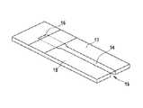
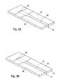
- FIG. 3Ashows a test element 13 produced in accordance with the method according to the invention.
- the test element 13has a carrier 18 and a capillary channel 14 located in said carrier 18 , said channel running from an application zone 15 for a liquid sample to a detection zone 16 for determining an analyte in the sample.
- the carrier 18comprises a polymer, such as PET.
- the polymer surface in the interior of the capillary channel 14was hydrophilized by irradiation with laser light.
- FIG. 3Bshows a test element 13 with a design corresponding to that of FIG. 3A , in which, additionally, the polymer surface 17 in the vicinity of the capillary channel 14 , particularly in the region around the application zone 15 , has been hydrophobized by irradiation with laser light.
- the term “substantially”is utilized herein to represent the inherent degree of uncertainty that may be attributed to any quantitative comparison, value, measurement, or other representation.
- the term “substantially”is also utilized herein to represent the degree by which a quantitative representation may vary from a stated reference without resulting in a change in the basic function of the subject matter at issue.
Landscapes
- Health & Medical Sciences (AREA)
- Engineering & Computer Science (AREA)
- Life Sciences & Earth Sciences (AREA)
- Chemical & Material Sciences (AREA)
- General Health & Medical Sciences (AREA)
- Hematology (AREA)
- Manufacturing & Machinery (AREA)
- Analytical Chemistry (AREA)
- Molecular Biology (AREA)
- Immunology (AREA)
- Microelectronics & Electronic Packaging (AREA)
- Biomedical Technology (AREA)
- Pathology (AREA)
- Urology & Nephrology (AREA)
- Physics & Mathematics (AREA)
- Biochemistry (AREA)
- General Physics & Mathematics (AREA)
- Chemical Kinetics & Catalysis (AREA)
- Clinical Laboratory Science (AREA)
- Toxicology (AREA)
- Food Science & Technology (AREA)
- Medicinal Chemistry (AREA)
- Biotechnology (AREA)
- Cell Biology (AREA)
- Microbiology (AREA)
- Automatic Analysis And Handling Materials Therefor (AREA)
- Physical Or Chemical Processes And Apparatus (AREA)
- Treatments Of Macromolecular Shaped Articles (AREA)
- Micromachines (AREA)
- Investigating Or Analysing Biological Materials (AREA)
Abstract
Description
- A diode-pumped solid state laser in the 4f mode: wavelength 266 nm, pulse width 25 ns, repetition rate 30 kHz,
pulse energy 10 μJ, hatch distance (=laser spot overlap, corresponding to the mean structure spacing, for example from trough to trough) 6 μm,beam diameter 18 μm; - A regenerative amplifier picosecond laser: wavelength 1064 nm,
pulse width 12 ps,repetition rate 50 kHz, pulse energy 30 μJ,hatch distance 12 μm, beam diameter 20 μm; and - A KrF excimer laser: wavelength 248 nm, pulse width 30 ns, repetition rate 100 Hz, pulse energy 400 to 500 mJ,
hatch distance 10 μm,beam diameter 10 μm.
- A diode-pumped solid state laser in the 4f mode: wavelength 266 nm, pulse width 25 ns, repetition rate 30 kHz,
Claims (21)
Applications Claiming Priority (4)
| Application Number | Priority Date | Filing Date | Title |
|---|---|---|---|
| EP07111621.4 | 2007-07-03 | ||
| EP07111621AEP2011629A1 (en) | 2007-07-03 | 2007-07-03 | Method for manufacturing a microfluid system on a polymer surface |
| EP07111621 | 2007-07-03 | ||
| PCT/EP2008/057862WO2009003856A1 (en) | 2007-07-03 | 2008-06-20 | Method for the production of a microfluidic system on a polymer surface |
Related Parent Applications (1)
| Application Number | Title | Priority Date | Filing Date |
|---|---|---|---|
| PCT/EP2008/057862ContinuationWO2009003856A1 (en) | 2007-07-03 | 2008-06-20 | Method for the production of a microfluidic system on a polymer surface |
Publications (2)
| Publication Number | Publication Date |
|---|---|
| US20100172799A1 US20100172799A1 (en) | 2010-07-08 |
| US8828333B2true US8828333B2 (en) | 2014-09-09 |
Family
ID=38515789
Family Applications (1)
| Application Number | Title | Priority Date | Filing Date |
|---|---|---|---|
| US12/651,886Active2028-08-23US8828333B2 (en) | 2007-07-03 | 2010-01-04 | Method for the production of a microfluidic system on a polymer surface |
Country Status (10)
| Country | Link |
|---|---|
| US (1) | US8828333B2 (en) |
| EP (2) | EP2011629A1 (en) |
| JP (1) | JP2010532269A (en) |
| KR (1) | KR101158381B1 (en) |
| CN (1) | CN101778712B (en) |
| CA (1) | CA2690165C (en) |
| ES (1) | ES2553409T3 (en) |
| MX (1) | MX2009013459A (en) |
| PL (1) | PL2170582T3 (en) |
| WO (1) | WO2009003856A1 (en) |
Families Citing this family (20)
| Publication number | Priority date | Publication date | Assignee | Title |
|---|---|---|---|---|
| EP2011629A1 (en) | 2007-07-03 | 2009-01-07 | F. Hoffman-la Roche AG | Method for manufacturing a microfluid system on a polymer surface |
| DE102008018170B4 (en) | 2008-04-03 | 2010-05-12 | NMI Naturwissenschaftliches und Medizinisches Institut an der Universität Tübingen | Microfluidic system and method for the construction and subsequent cultivation and subsequent investigation of complex cell arrays |
| DE102009039956A1 (en)* | 2009-08-27 | 2011-03-10 | NMI Naturwissenschaftliches und Medizinisches Institut an der Universität Tübingen | Microfluidic system and method for its production |
| EP2545853B1 (en) | 2010-03-09 | 2017-10-25 | ARKRAY, Inc. | Electrochemical sensor |
| US8790594B2 (en)* | 2010-04-23 | 2014-07-29 | Georgia Tech Research Corporation | Patterning of surfaces to control the storage, mobility and transport of liquids for microfluidic applications |
| JP5551632B2 (en)* | 2011-02-17 | 2014-07-16 | 浜松ホトニクス株式会社 | Surface treatment method and surface treatment apparatus for sample manipulation element |
| DE102011121018A1 (en) | 2011-12-13 | 2013-06-13 | Sartorius Stedim Biotech Gmbh | Hydrophobic or oleophobic microporous polymer membrane with structurally induced Abperl effect |
| US9236271B2 (en)* | 2012-04-18 | 2016-01-12 | Globalfoundries Inc. | Laser-initiated exfoliation of group III-nitride films and applications for layer transfer and patterning |
| JP6473285B2 (en)* | 2012-12-05 | 2019-02-20 | 株式会社ミマキエンジニアリング | Resin pile decoration method |
| FR3003689B1 (en)* | 2013-03-25 | 2016-11-25 | Commissariat Energie Atomique | CAPILLARY SELF-ASSEMBLY SUPPORT WITH HORIZONTAL STABILIZATION, METHOD OF MANUFACTURE AND USE |
| US9297118B2 (en) | 2013-06-07 | 2016-03-29 | Georgia Tech Research Corporation | Superamphiphobic paper |
| CN103769750B (en)* | 2014-01-22 | 2016-01-13 | 北京工业大学 | Method for making strontium titanate surface superhydrophilic by using picosecond laser |
| ES2574577B1 (en)* | 2014-12-19 | 2017-03-28 | Bsh Electrodomésticos España, S.A. | Method for manufacturing a household appliance component with double surface structuring, and household appliance component |
| EP3344389B1 (en) | 2015-09-02 | 2020-06-10 | Illumina Cambridge Limited | Method of fixing defects in a hydrophobic surface of a droplet actuator |
| EP3458857B8 (en)* | 2016-05-19 | 2024-05-01 | The Board of Trustees of the Leland Stanford Junior University | Systems and methods for automated single cell cytological classification in flow |
| CN107651689B (en)* | 2017-10-23 | 2020-04-03 | 西北工业大学 | A kind of method to improve the wettability of silicon carbide surface |
| CN110395689B (en)* | 2019-06-24 | 2024-03-22 | 金华职业技术学院 | Assembly method of microparticles |
| WO2022101860A1 (en)* | 2020-11-13 | 2022-05-19 | Orbis Diagnostics Limited | Methods for establishing hydrophilic and hydrophobic areas on a surface of a substrate or film and associated microfludic devices |
| CN112666050B (en)* | 2020-11-30 | 2023-06-02 | 江苏科技大学 | A functional surface hydrophilic performance testing device and characterization method |
| CN114871082A (en)* | 2021-06-30 | 2022-08-09 | 法国圣戈班玻璃公司 | Product component with a microstructure, method for obtaining information therefrom, identification device and processing method |
Citations (21)
| Publication number | Priority date | Publication date | Assignee | Title |
|---|---|---|---|---|
| WO1996004123A1 (en) | 1994-07-29 | 1996-02-15 | Wilhelm Barthlott | Self-cleaning surfaces of objects and process for producing same |
| WO1998023957A1 (en) | 1996-11-27 | 1998-06-04 | Ecole Polytechnique Federale De Lausanne (Laboratoire D'electrochimie) | Surface patterning of affinity reagents using photoablation |
| DE19753847A1 (en) | 1997-12-04 | 1999-06-10 | Roche Diagnostics Gmbh | Analytical test element with capillary channel |
| WO2000058410A1 (en) | 1999-03-25 | 2000-10-05 | Wilhelm Barthlott | Method of producing self-cleaning detachable surfaces |
| WO2000058415A1 (en) | 1999-03-25 | 2000-10-05 | Wilhelm Barthlott | Method and device for the loss-free transport of liquids |
| GB2350678A (en) | 1998-05-08 | 2000-12-06 | Amersham Pharm Biotech Ab | Microfluidic device |
| US6271040B1 (en) | 1992-05-21 | 2001-08-07 | Biosite Diagnostics Incorporated | Diagnostic devices method and apparatus for the controlled movement of reagents without membranes |
| WO2001056771A2 (en) | 2000-01-31 | 2001-08-09 | Walter Schmidt | Method for fabricating micro-structures with various surface properties in multilayer body by plasma etching |
| US20020150683A1 (en)* | 2000-11-02 | 2002-10-17 | Troian Sandra M. | Method and device for controlling liquid flow on the surface of a microfluidic chip |
| US20030013147A1 (en) | 2000-02-25 | 2003-01-16 | Karlheinz Hildenbrand | Test system based on microcapillaries |
| US20030044322A1 (en)* | 2001-08-28 | 2003-03-06 | Gyros Ab | Retaining microfluidic microcavity and other microfluidic structures |
| US20040028566A1 (en)* | 2002-08-08 | 2004-02-12 | Ko Jong Soo | Microfluidic device for the controlled movement of fluid |
| US20040067166A1 (en) | 2002-10-08 | 2004-04-08 | Karinka Shridhara Alva | Device having a flow channel |
| US20040115831A1 (en)* | 2002-04-19 | 2004-06-17 | Meathrel William G. | Diagnostic devices for use in the assaying of biological fluids |
| US20040265365A1 (en) | 2003-06-30 | 2004-12-30 | Daddona Peter E. | Method for coating skin piercing microprojections |
| CA2549143A1 (en) | 2003-12-04 | 2005-06-16 | Rudolf Pachl | Coated test elements |
| US20060159838A1 (en)* | 2005-01-14 | 2006-07-20 | Cabot Corporation | Controlling ink migration during the formation of printable electronic features |
| WO2006074665A2 (en) | 2005-01-12 | 2006-07-20 | Inverness Medical Switzerland Gmbh | A method of producing a microfluidic device and microfluidic devices |
| US20060234269A1 (en) | 2005-04-18 | 2006-10-19 | Matthew Asplund | Laser Modification and Functionalization of Substrates |
| US20080257355A1 (en)* | 2007-04-18 | 2008-10-23 | Rao Chamkurkishtiah P | Self-cleaning and sterilizing endotracheal and tracheostomy tube |
| US20100172799A1 (en) | 2007-07-03 | 2010-07-08 | Josef Roeper | Method for the production of a microfluidic system on a polymer surface |
Family Cites Families (11)
| Publication number | Priority date | Publication date | Assignee | Title |
|---|---|---|---|---|
| CA2137632A1 (en)* | 1993-12-17 | 1995-06-18 | Douglas S. Dunn | Ablative flashlamp imaging |
| FR2783179B1 (en)* | 1998-09-16 | 2000-10-06 | Commissariat Energie Atomique | CHEMICAL OR BIOLOGICAL ANALYSIS DEVICE COMPRISING A PLURALITY OF ANALYSIS SITES ON A MEDIUM, AND ITS MANUFACTURING METHOD |
| AU6402900A (en)* | 1999-06-08 | 2000-12-28 | Biomicro Systems, Inc. | Laser ablation of doped fluorocarbon materials and applications thereof |
| US7020355B2 (en)* | 2001-11-02 | 2006-03-28 | Massachusetts Institute Of Technology | Switchable surfaces |
| DE10224568A1 (en)* | 2001-12-10 | 2004-02-19 | Sartorius Ag | Microarray device |
| JP4255297B2 (en)* | 2003-03-17 | 2009-04-15 | 財団法人川村理化学研究所 | SUBSTRATE FOR MICRO CHEMICAL PROCESS AND METHOD FOR PRODUCING THE SAME |
| DE10333770A1 (en)* | 2003-07-22 | 2005-02-17 | Carl Zeiss Meditec Ag | Method for material processing with laser pulses of large spectral bandwidth and apparatus for carrying out the method |
| JP4385166B2 (en)* | 2003-10-03 | 2009-12-16 | 独立行政法人産業技術総合研究所 | Fluid control method |
| JP2005321266A (en)* | 2004-05-07 | 2005-11-17 | Nippon Sheet Glass Co Ltd | Chip for microchemical system |
| JP4638255B2 (en)* | 2005-02-28 | 2011-02-23 | テルモ株式会社 | Cell culture device, instrument and system |
| EP1926679A2 (en)* | 2005-09-09 | 2008-06-04 | Koninklijke Philips Electronics N.V. | A method of manufacturing a microsystem, such a microsystem, a stack of foils comprising such a microsystem, an electronic device comprising such a microsystem and use of the electronic device |
- 2007
- 2007-07-03EPEP07111621Apatent/EP2011629A1/ennot_activeWithdrawn
- 2008
- 2008-06-20ESES08774167.4Tpatent/ES2553409T3/enactiveActive
- 2008-06-20WOPCT/EP2008/057862patent/WO2009003856A1/enactiveApplication Filing
- 2008-06-20JPJP2010513864Apatent/JP2010532269A/enactivePending
- 2008-06-20PLPL08774167Tpatent/PL2170582T3/enunknown
- 2008-06-20CACA2690165Apatent/CA2690165C/ennot_activeExpired - Fee Related
- 2008-06-20MXMX2009013459Apatent/MX2009013459A/enunknown
- 2008-06-20KRKR1020097027525Apatent/KR101158381B1/ennot_activeExpired - Fee Related
- 2008-06-20EPEP08774167.4Apatent/EP2170582B1/enactiveActive
- 2008-06-20CNCN200880023042.XApatent/CN101778712B/enactiveActive
- 2010
- 2010-01-04USUS12/651,886patent/US8828333B2/enactiveActive
Patent Citations (26)
| Publication number | Priority date | Publication date | Assignee | Title |
|---|---|---|---|---|
| US6271040B1 (en) | 1992-05-21 | 2001-08-07 | Biosite Diagnostics Incorporated | Diagnostic devices method and apparatus for the controlled movement of reagents without membranes |
| US6660363B1 (en) | 1994-07-29 | 2003-12-09 | Wilhelm Barthlott | Self-cleaning surfaces of objects and process for producing same |
| WO1996004123A1 (en) | 1994-07-29 | 1996-02-15 | Wilhelm Barthlott | Self-cleaning surfaces of objects and process for producing same |
| WO1998023957A1 (en) | 1996-11-27 | 1998-06-04 | Ecole Polytechnique Federale De Lausanne (Laboratoire D'electrochimie) | Surface patterning of affinity reagents using photoablation |
| DE19753847A1 (en) | 1997-12-04 | 1999-06-10 | Roche Diagnostics Gmbh | Analytical test element with capillary channel |
| US7008799B1 (en) | 1997-12-04 | 2006-03-07 | Roche Diagnostics Gmbh | Analytical test element with a capillary channel |
| GB2350678A (en) | 1998-05-08 | 2000-12-06 | Amersham Pharm Biotech Ab | Microfluidic device |
| US20050136217A1 (en) | 1999-03-25 | 2005-06-23 | Wilhelm Barthlott | Method for the preparation of self-cleaning removable surfaces |
| WO2000058415A1 (en) | 1999-03-25 | 2000-10-05 | Wilhelm Barthlott | Method and device for the loss-free transport of liquids |
| WO2000058410A1 (en) | 1999-03-25 | 2000-10-05 | Wilhelm Barthlott | Method of producing self-cleaning detachable surfaces |
| WO2001056771A2 (en) | 2000-01-31 | 2001-08-09 | Walter Schmidt | Method for fabricating micro-structures with various surface properties in multilayer body by plasma etching |
| US20030013147A1 (en) | 2000-02-25 | 2003-01-16 | Karlheinz Hildenbrand | Test system based on microcapillaries |
| US20020150683A1 (en)* | 2000-11-02 | 2002-10-17 | Troian Sandra M. | Method and device for controlling liquid flow on the surface of a microfluidic chip |
| US20030044322A1 (en)* | 2001-08-28 | 2003-03-06 | Gyros Ab | Retaining microfluidic microcavity and other microfluidic structures |
| US20040115831A1 (en)* | 2002-04-19 | 2004-06-17 | Meathrel William G. | Diagnostic devices for use in the assaying of biological fluids |
| US20040028566A1 (en)* | 2002-08-08 | 2004-02-12 | Ko Jong Soo | Microfluidic device for the controlled movement of fluid |
| US20040067166A1 (en) | 2002-10-08 | 2004-04-08 | Karinka Shridhara Alva | Device having a flow channel |
| US20040265365A1 (en) | 2003-06-30 | 2004-12-30 | Daddona Peter E. | Method for coating skin piercing microprojections |
| CA2549143A1 (en) | 2003-12-04 | 2005-06-16 | Rudolf Pachl | Coated test elements |
| WO2005054845A1 (en) | 2003-12-04 | 2005-06-16 | Roche Diagnostics Gmbh | Coated test elements |
| US20070110613A1 (en) | 2003-12-04 | 2007-05-17 | Rudolf Pachl | Coated test elements |
| WO2006074665A2 (en) | 2005-01-12 | 2006-07-20 | Inverness Medical Switzerland Gmbh | A method of producing a microfluidic device and microfluidic devices |
| US20060159838A1 (en)* | 2005-01-14 | 2006-07-20 | Cabot Corporation | Controlling ink migration during the formation of printable electronic features |
| US20060234269A1 (en) | 2005-04-18 | 2006-10-19 | Matthew Asplund | Laser Modification and Functionalization of Substrates |
| US20080257355A1 (en)* | 2007-04-18 | 2008-10-23 | Rao Chamkurkishtiah P | Self-cleaning and sterilizing endotracheal and tracheostomy tube |
| US20100172799A1 (en) | 2007-07-03 | 2010-07-08 | Josef Roeper | Method for the production of a microfluidic system on a polymer surface |
Non-Patent Citations (1)
| Title |
|---|
| Pfleging et al. "Laser-Assisted Modification of Polymers for Microfluidic, Microoptics and Cell Culture Applications", Mar. 8, 2007, SPIE, Laser-based Micro- and Nanopackaging and Assembly, vol. 6459.* |
Also Published As
| Publication number | Publication date |
|---|---|
| KR101158381B1 (en) | 2012-06-22 |
| CA2690165A1 (en) | 2009-01-08 |
| PL2170582T3 (en) | 2016-01-29 |
| ES2553409T3 (en) | 2015-12-09 |
| KR20100018591A (en) | 2010-02-17 |
| WO2009003856A1 (en) | 2009-01-08 |
| CA2690165C (en) | 2012-04-24 |
| CN101778712B (en) | 2014-08-13 |
| JP2010532269A (en) | 2010-10-07 |
| CN101778712A (en) | 2010-07-14 |
| US20100172799A1 (en) | 2010-07-08 |
| MX2009013459A (en) | 2010-01-15 |
| HK1146015A1 (en) | 2011-05-13 |
| EP2011629A1 (en) | 2009-01-07 |
| EP2170582B1 (en) | 2015-08-26 |
| EP2170582A1 (en) | 2010-04-07 |
Similar Documents
| Publication | Publication Date | Title |
|---|---|---|
| US8828333B2 (en) | Method for the production of a microfluidic system on a polymer surface | |
| Agha et al. | A review of cyclic olefin copolymer applications in microfluidics and microdevices | |
| Klank et al. | CO 2-laser micromachining and back-end processing for rapid production of PMMA-based microfluidic systems | |
| DE60105979T2 (en) | METHOD FOR PRODUCING MICROSTRUCTURES WITH DIFFERENT SURFACE PROPERTIES IN A MULTILAYER BODY BY PLASMA SETS | |
| US20040022691A1 (en) | Method of manufacturing and design of microreactors, including microanalytical and separation devices | |
| Toudeshkchoui et al. | Microfluidic devices with gold thin film channels for chemical and biomedical applications: a review | |
| US20110041922A1 (en) | Controlled liquid handling | |
| JP2009128342A (en) | Microchip and its manufacturing method | |
| EP1683570A1 (en) | Method of controlling fluid | |
| EP0944834B1 (en) | Surface patterning of affinity reagents using photoablation | |
| CA2688305C (en) | Method for the production of an analytical element | |
| Bagga et al. | Nanoparticle functionalized laser patterned substrate: an innovative route towards low cost biomimetic platforms | |
| JP4072175B2 (en) | Substrate bonding method, chip forming method, and chip | |
| KR101515394B1 (en) | Microfluidic device for cell lysis, and method for cell lysis using the same | |
| HK1146015B (en) | Method for the production of a microfluidic system on a polymer surface | |
| JP2002283293A (en) | Microfluidic device and method of manufacturing the same | |
| Atkin et al. | Disposable biochip fabrication for DNA diagnostics | |
| JP2009103624A (en) | Microchannel substrate, and liquid controller arranged therewith | |
| Thomson et al. | Protein patterning in polycarbonate microfluidic channels | |
| Pfleging et al. | Patterning of polystyrene by UV-laser radiation for the fabrication of devices for patch clamping | |
| JP5137009B2 (en) | Microchip manufacturing method | |
| Sugioka | Nanofluidics Fabricated By 3D Femtosecond Laser Processing | |
| Bremus-Koebberling et al. | Laser structuring and modification of polymer surfaces for chemical and medical micro components | |
| HK1142296B (en) | Method for the production of an analytical element | |
| Mahlberg | Portable Microfluidic Platform Employing Young-Laplace Pumping for Multiplexed Lab-On-A-Chip Applications |
Legal Events
| Date | Code | Title | Description |
|---|---|---|---|
| AS | Assignment | Owner name:ROCHE DIAGNOSTICS GMBH, GERMANY Free format text:ASSIGNMENT OF ASSIGNORS INTEREST;ASSIGNORS:ROEPER, JOSEF;URLAUB, EVA;FINKE, WERNER;SIGNING DATES FROM 20100128 TO 20100210;REEL/FRAME:024100/0019 Owner name:ROCHE DIAGNOSTICS OPERATIONS, INC., INDIANA Free format text:ASSIGNMENT OF ASSIGNORS INTEREST;ASSIGNOR:ROCHE DIAGNOSTICS GMBH;REEL/FRAME:024100/0037 Effective date:20100224 | |
| STCF | Information on status: patent grant | Free format text:PATENTED CASE | |
| AS | Assignment | Owner name:ROCHE DIABETES CARE, INC., INDIANA Free format text:ASSIGNMENT OF ASSIGNORS INTEREST;ASSIGNOR:ROCHE DIAGNOSTICS OPERATIONS, INC.;REEL/FRAME:036008/0670 Effective date:20150302 | |
| MAFP | Maintenance fee payment | Free format text:PAYMENT OF MAINTENANCE FEE, 4TH YEAR, LARGE ENTITY (ORIGINAL EVENT CODE: M1551) Year of fee payment:4 | |
| MAFP | Maintenance fee payment | Free format text:PAYMENT OF MAINTENANCE FEE, 8TH YEAR, LARGE ENTITY (ORIGINAL EVENT CODE: M1552); ENTITY STATUS OF PATENT OWNER: LARGE ENTITY Year of fee payment:8 |