US8828089B1 - Augmenting an acetabular implant site - Google Patents
Augmenting an acetabular implant siteDownload PDFInfo
- Publication number
- US8828089B1 US8828089B1US12/834,447US83444710AUS8828089B1US 8828089 B1US8828089 B1US 8828089B1US 83444710 AUS83444710 AUS 83444710AUS 8828089 B1US8828089 B1US 8828089B1
- Authority
- US
- United States
- Prior art keywords
- trial
- buttress
- affixation
- acetabular
- natural bone
- Prior art date
- Legal status (The legal status is an assumption and is not a legal conclusion. Google has not performed a legal analysis and makes no representation as to the accuracy of the status listed.)
- Active, expires
Links
Images


Classifications
- A—HUMAN NECESSITIES
- A61—MEDICAL OR VETERINARY SCIENCE; HYGIENE
- A61F—FILTERS IMPLANTABLE INTO BLOOD VESSELS; PROSTHESES; DEVICES PROVIDING PATENCY TO, OR PREVENTING COLLAPSING OF, TUBULAR STRUCTURES OF THE BODY, e.g. STENTS; ORTHOPAEDIC, NURSING OR CONTRACEPTIVE DEVICES; FOMENTATION; TREATMENT OR PROTECTION OF EYES OR EARS; BANDAGES, DRESSINGS OR ABSORBENT PADS; FIRST-AID KITS
- A61F2/00—Filters implantable into blood vessels; Prostheses, i.e. artificial substitutes or replacements for parts of the body; Appliances for connecting them with the body; Devices providing patency to, or preventing collapsing of, tubular structures of the body, e.g. stents
- A61F2/02—Prostheses implantable into the body
- A61F2/30—Joints
- A61F2/30721—Accessories
- A61F2/30734—Modular inserts, sleeves or augments, e.g. placed on proximal part of stem for fixation purposes or wedges for bridging a bone defect
- A—HUMAN NECESSITIES
- A61—MEDICAL OR VETERINARY SCIENCE; HYGIENE
- A61F—FILTERS IMPLANTABLE INTO BLOOD VESSELS; PROSTHESES; DEVICES PROVIDING PATENCY TO, OR PREVENTING COLLAPSING OF, TUBULAR STRUCTURES OF THE BODY, e.g. STENTS; ORTHOPAEDIC, NURSING OR CONTRACEPTIVE DEVICES; FOMENTATION; TREATMENT OR PROTECTION OF EYES OR EARS; BANDAGES, DRESSINGS OR ABSORBENT PADS; FIRST-AID KITS
- A61F2/00—Filters implantable into blood vessels; Prostheses, i.e. artificial substitutes or replacements for parts of the body; Appliances for connecting them with the body; Devices providing patency to, or preventing collapsing of, tubular structures of the body, e.g. stents
- A61F2/02—Prostheses implantable into the body
- A61F2/30—Joints
- A61F2/32—Joints for the hip
- A61F2/34—Acetabular cups
- A—HUMAN NECESSITIES
- A61—MEDICAL OR VETERINARY SCIENCE; HYGIENE
- A61F—FILTERS IMPLANTABLE INTO BLOOD VESSELS; PROSTHESES; DEVICES PROVIDING PATENCY TO, OR PREVENTING COLLAPSING OF, TUBULAR STRUCTURES OF THE BODY, e.g. STENTS; ORTHOPAEDIC, NURSING OR CONTRACEPTIVE DEVICES; FOMENTATION; TREATMENT OR PROTECTION OF EYES OR EARS; BANDAGES, DRESSINGS OR ABSORBENT PADS; FIRST-AID KITS
- A61F2/00—Filters implantable into blood vessels; Prostheses, i.e. artificial substitutes or replacements for parts of the body; Appliances for connecting them with the body; Devices providing patency to, or preventing collapsing of, tubular structures of the body, e.g. stents
- A61F2/02—Prostheses implantable into the body
- A61F2/30—Joints
- A61F2002/30001—Additional features of subject-matter classified in A61F2/28, A61F2/30 and subgroups thereof
- A61F2002/30316—The prosthesis having different structural features at different locations within the same prosthesis; Connections between prosthetic parts; Special structural features of bone or joint prostheses not otherwise provided for
- A61F2002/30329—Connections or couplings between prosthetic parts, e.g. between modular parts; Connecting elements
- A61F2002/30471—Connections or couplings between prosthetic parts, e.g. between modular parts; Connecting elements connected by a hinged linkage mechanism, e.g. of the single-bar or multi-bar linkage type
- A—HUMAN NECESSITIES
- A61—MEDICAL OR VETERINARY SCIENCE; HYGIENE
- A61F—FILTERS IMPLANTABLE INTO BLOOD VESSELS; PROSTHESES; DEVICES PROVIDING PATENCY TO, OR PREVENTING COLLAPSING OF, TUBULAR STRUCTURES OF THE BODY, e.g. STENTS; ORTHOPAEDIC, NURSING OR CONTRACEPTIVE DEVICES; FOMENTATION; TREATMENT OR PROTECTION OF EYES OR EARS; BANDAGES, DRESSINGS OR ABSORBENT PADS; FIRST-AID KITS
- A61F2/00—Filters implantable into blood vessels; Prostheses, i.e. artificial substitutes or replacements for parts of the body; Appliances for connecting them with the body; Devices providing patency to, or preventing collapsing of, tubular structures of the body, e.g. stents
- A61F2/02—Prostheses implantable into the body
- A61F2/30—Joints
- A61F2002/30001—Additional features of subject-matter classified in A61F2/28, A61F2/30 and subgroups thereof
- A61F2002/30316—The prosthesis having different structural features at different locations within the same prosthesis; Connections between prosthetic parts; Special structural features of bone or joint prostheses not otherwise provided for
- A61F2002/30329—Connections or couplings between prosthetic parts, e.g. between modular parts; Connecting elements
- A61F2002/30476—Connections or couplings between prosthetic parts, e.g. between modular parts; Connecting elements locked by an additional locking mechanism
- A61F2002/30505—Connections or couplings between prosthetic parts, e.g. between modular parts; Connecting elements locked by an additional locking mechanism spring biased
- A—HUMAN NECESSITIES
- A61—MEDICAL OR VETERINARY SCIENCE; HYGIENE
- A61F—FILTERS IMPLANTABLE INTO BLOOD VESSELS; PROSTHESES; DEVICES PROVIDING PATENCY TO, OR PREVENTING COLLAPSING OF, TUBULAR STRUCTURES OF THE BODY, e.g. STENTS; ORTHOPAEDIC, NURSING OR CONTRACEPTIVE DEVICES; FOMENTATION; TREATMENT OR PROTECTION OF EYES OR EARS; BANDAGES, DRESSINGS OR ABSORBENT PADS; FIRST-AID KITS
- A61F2/00—Filters implantable into blood vessels; Prostheses, i.e. artificial substitutes or replacements for parts of the body; Appliances for connecting them with the body; Devices providing patency to, or preventing collapsing of, tubular structures of the body, e.g. stents
- A61F2/02—Prostheses implantable into the body
- A61F2/30—Joints
- A61F2002/30001—Additional features of subject-matter classified in A61F2/28, A61F2/30 and subgroups thereof
- A61F2002/30316—The prosthesis having different structural features at different locations within the same prosthesis; Connections between prosthetic parts; Special structural features of bone or joint prostheses not otherwise provided for
- A61F2002/30329—Connections or couplings between prosthetic parts, e.g. between modular parts; Connecting elements
- A61F2002/30476—Connections or couplings between prosthetic parts, e.g. between modular parts; Connecting elements locked by an additional locking mechanism
- A61F2002/30507—Connections or couplings between prosthetic parts, e.g. between modular parts; Connecting elements locked by an additional locking mechanism using a threaded locking member, e.g. a locking screw or a set screw
- A—HUMAN NECESSITIES
- A61—MEDICAL OR VETERINARY SCIENCE; HYGIENE
- A61F—FILTERS IMPLANTABLE INTO BLOOD VESSELS; PROSTHESES; DEVICES PROVIDING PATENCY TO, OR PREVENTING COLLAPSING OF, TUBULAR STRUCTURES OF THE BODY, e.g. STENTS; ORTHOPAEDIC, NURSING OR CONTRACEPTIVE DEVICES; FOMENTATION; TREATMENT OR PROTECTION OF EYES OR EARS; BANDAGES, DRESSINGS OR ABSORBENT PADS; FIRST-AID KITS
- A61F2/00—Filters implantable into blood vessels; Prostheses, i.e. artificial substitutes or replacements for parts of the body; Appliances for connecting them with the body; Devices providing patency to, or preventing collapsing of, tubular structures of the body, e.g. stents
- A61F2/02—Prostheses implantable into the body
- A61F2/30—Joints
- A61F2002/30001—Additional features of subject-matter classified in A61F2/28, A61F2/30 and subgroups thereof
- A61F2002/30316—The prosthesis having different structural features at different locations within the same prosthesis; Connections between prosthetic parts; Special structural features of bone or joint prostheses not otherwise provided for
- A61F2002/30535—Special structural features of bone or joint prostheses not otherwise provided for
- A61F2002/30537—Special structural features of bone or joint prostheses not otherwise provided for adjustable
- A61F2002/30538—Special structural features of bone or joint prostheses not otherwise provided for adjustable for adjusting angular orientation
- A—HUMAN NECESSITIES
- A61—MEDICAL OR VETERINARY SCIENCE; HYGIENE
- A61F—FILTERS IMPLANTABLE INTO BLOOD VESSELS; PROSTHESES; DEVICES PROVIDING PATENCY TO, OR PREVENTING COLLAPSING OF, TUBULAR STRUCTURES OF THE BODY, e.g. STENTS; ORTHOPAEDIC, NURSING OR CONTRACEPTIVE DEVICES; FOMENTATION; TREATMENT OR PROTECTION OF EYES OR EARS; BANDAGES, DRESSINGS OR ABSORBENT PADS; FIRST-AID KITS
- A61F2/00—Filters implantable into blood vessels; Prostheses, i.e. artificial substitutes or replacements for parts of the body; Appliances for connecting them with the body; Devices providing patency to, or preventing collapsing of, tubular structures of the body, e.g. stents
- A61F2/02—Prostheses implantable into the body
- A61F2/30—Joints
- A61F2002/30001—Additional features of subject-matter classified in A61F2/28, A61F2/30 and subgroups thereof
- A61F2002/30316—The prosthesis having different structural features at different locations within the same prosthesis; Connections between prosthetic parts; Special structural features of bone or joint prostheses not otherwise provided for
- A61F2002/30535—Special structural features of bone or joint prostheses not otherwise provided for
- A61F2002/30576—Special structural features of bone or joint prostheses not otherwise provided for with extending fixation tabs
- A61F2002/30578—Special structural features of bone or joint prostheses not otherwise provided for with extending fixation tabs having apertures, e.g. for receiving fixation screws
- A—HUMAN NECESSITIES
- A61—MEDICAL OR VETERINARY SCIENCE; HYGIENE
- A61F—FILTERS IMPLANTABLE INTO BLOOD VESSELS; PROSTHESES; DEVICES PROVIDING PATENCY TO, OR PREVENTING COLLAPSING OF, TUBULAR STRUCTURES OF THE BODY, e.g. STENTS; ORTHOPAEDIC, NURSING OR CONTRACEPTIVE DEVICES; FOMENTATION; TREATMENT OR PROTECTION OF EYES OR EARS; BANDAGES, DRESSINGS OR ABSORBENT PADS; FIRST-AID KITS
- A61F2/00—Filters implantable into blood vessels; Prostheses, i.e. artificial substitutes or replacements for parts of the body; Appliances for connecting them with the body; Devices providing patency to, or preventing collapsing of, tubular structures of the body, e.g. stents
- A61F2/02—Prostheses implantable into the body
- A61F2/30—Joints
- A61F2002/30001—Additional features of subject-matter classified in A61F2/28, A61F2/30 and subgroups thereof
- A61F2002/30316—The prosthesis having different structural features at different locations within the same prosthesis; Connections between prosthetic parts; Special structural features of bone or joint prostheses not otherwise provided for
- A61F2002/30535—Special structural features of bone or joint prostheses not otherwise provided for
- A61F2002/30617—Visible markings for adjusting, locating or measuring
- A—HUMAN NECESSITIES
- A61—MEDICAL OR VETERINARY SCIENCE; HYGIENE
- A61F—FILTERS IMPLANTABLE INTO BLOOD VESSELS; PROSTHESES; DEVICES PROVIDING PATENCY TO, OR PREVENTING COLLAPSING OF, TUBULAR STRUCTURES OF THE BODY, e.g. STENTS; ORTHOPAEDIC, NURSING OR CONTRACEPTIVE DEVICES; FOMENTATION; TREATMENT OR PROTECTION OF EYES OR EARS; BANDAGES, DRESSINGS OR ABSORBENT PADS; FIRST-AID KITS
- A61F2/00—Filters implantable into blood vessels; Prostheses, i.e. artificial substitutes or replacements for parts of the body; Appliances for connecting them with the body; Devices providing patency to, or preventing collapsing of, tubular structures of the body, e.g. stents
- A61F2/02—Prostheses implantable into the body
- A61F2/30—Joints
- A61F2/30721—Accessories
- A61F2/30734—Modular inserts, sleeves or augments, e.g. placed on proximal part of stem for fixation purposes or wedges for bridging a bone defect
- A61F2002/30736—Augments or augmentation pieces, e.g. wedges or blocks for bridging a bone defect
Definitions
- the present inventionrelates generally to augmenting an acetabular implant site to compensate for a deficiency encountered in the natural bone at the implant site and pertains, more specifically, to a system of implements and acetabular augmentation components, and methods for implanting an augment component at an acetabular implant site.
- the present inventionprovides a surgeon with multiple options for addressing a wide range of bone deficiencies encountered at acetabular implant sites, enabling a simplified procedure that quickly and effectively compensates for these deficiencies, with minimal patient trauma.
- the present inventionattains several objects and advantages, some of which are summarized as follows: Provides a system that enables a surgeon to select optimum compensation for an acetabular bone deficiency encountered at a particular acetabular implant site, and to do so intra-operatively, with increased accuracy, ease and dispatch, so as to minimize patient trauma; enables quick and effective compensation for acetabular bone deficiencies as an alternative to current procedures which require time-consuming preparation and use of structural allografts; provides a modular system for augmenting natural bone at an acetabular implant site during hip arthroplasty to compensate for deficiencies encountered in the natural bone at the implant site and thereby accommodate the needs of a particular patient accurately, without requiring a specific, custom-created implant component; enables the use of any of a wide range of currently available acetabular components, at
- an acetabular augmentfor compensating for a deficiency encountered in natural bone at an implant site wherein an acetabular component of a prosthetic hip implant is to be implanted within a prepared acetabulum during a hip arthroplasty, with an outer surface of the acetabular component engaged with the prepared acetabulum along an acetabular envelope
- the acetabular augmentcomprising: a buttress member having a buttress surface with a surface contour configuration complementary to a corresponding portion of the acetabular envelope; an affixation member having an affixation surface for affixing the affixation member to natural bone adjacent the prepared acetabulum; and a coupling arrangement for coupling the buttress member with the affixation member, the coupling arrangement including coupling elements on the buttress member and on the affixation member for securing the buttress member to the affixation member with the
- the present inventionprovides a method of compensating for a deficiency encountered in natural bone at an implant site wherein an acetabular component of a prosthetic hip implant is to be implanted within a prepared acetabulum during a hip arthroplasty, with an outer surface of the acetabular component engaged with the prepared acetabulum along an acetabular envelope, the method comprising: providing a trial buttress member having a trial buttress surface with a surface contour configuration complementary to a corresponding portion of the acetabular envelope; providing a trial affixation member having an affixation surface for engaging natural bone adjacent the prepared acetabulum, the trial affixation member being coupled with the trial buttress member so as to enable selective placement of the trial affixation surface at a selected angular position relative to the trial buttress surface; placing the trial buttress surface in juxtaposition with the acetabular envelope at the deficiency and moving the trial affixation member relative to the trial buttress member to place the trial affixation
- the present inventionprovides a system for use in compensating for a deficiency encountered in natural bone at an implant site wherein an acetabular component of a prosthetic hip implant is to be implanted within a prepared acetabulum during a hip arthroplasty, with an outer surface of the acetabular component engaged with the prepared acetabulum along an acetabular envelope, the system comprising: a trial acetabular augment including a trial buttress member having a trial buttress surface with a surface contour configuration complementary to a corresponding portion of the acetabular envelope, a trial affixation member having an affixation surface for engaging natural bone adjacent the prepared acetabulum, the trial affixation member being coupled with the trial buttress member for selective angular movement relative to one another to enable selective placement of the trial affixation surface at a selected angular position relative to the trial buttress surface; a restraining mechanism for restraining relative angular movement between the trial affixation member and the trial buttress
- the present inventionincludes a trial acetabular augment for use in compensating for a deficiency encountered in natural bone at an implant site wherein an acetabular component of a prosthetic hip implant is to be implanted within a prepared acetabulum during a hip arthroplasty, with an outer surface of the acetabular component engaged with the prepared acetabulum along an acetabular envelope,
- the trial acetabular augmentcomprising: a trial buttress member having a trial buttress surface with a surface contour configuration complementary to a corresponding portion of the acetabular envelope; a trial affixation member having an affixation surface for engaging natural bone adjacent the prepared acetabulum, the trial affixation member being coupled with the trial buttress member for selective angular movement relative to one another to enable selective placement of the trial affixation surface at a selected angular position relative to the trial buttress surface; a restraining mechanism for restraining relative angular movement between the trial affixation member and the trial
- FIG. 1is a somewhat schematic pictorial view showing an acetabular implant site suffering from a deficiency in the natural bone;
- FIG. 2is a pictorial view of an acetabular augment constructed in accordance with the present invention.
- FIG. 3is an exploded pictorial view of the acetabular augment
- FIG. 4is a fragmentary cross-sectional view taken along line 4 - 4 of FIG. 3 ;
- FIG. 5is a fragmentary cross-sectional view taken along line 5 - 5 of FIG. 3 ;
- FIG. 6is a fragmentary cross-sectional view taken along line 6 - 6 of FIG. 3 ;
- FIG. 7is a top plan view of the fragment of FIG. 6 , with the inclusion of a component part illustrated in FIG. 3 ;
- FIG. 8is a top plan view similar to FIG. 7 and with component parts in another operating position;
- FIGS. 9 and 10are somewhat diagrammatic side elevational views illustrating a range of adjustment of the relative angular positions of component parts of the acetabular augment
- FIG. 11is a side elevational view of a trial acetabular augment constructed in accordance with the present invention.
- FIG. 12is an enlarged fragmentary view of a portion of the trial augment, partially in cross-section to show internal details
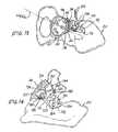
- FIGS. 13 through 17are pictorial views illustrating an acetabular implant site compensation method carried out in accordance with the present invention utilizing a system of the present invention
- FIG. 18is a pictorial view illustrating alternate component parts of the acetabular augment
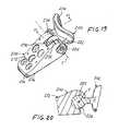
- FIG. 19is a pictorial view illustrating an alternate trial acetabular augment constructed in accordance with the present invention.
- FIG. 20is an enlarged fragmentary cross-sectional view taken along line 20 - 20 of FIG. 19 ;
- FIG. 21is a pictorial view illustrating another alternate trial acetabular augment constructed in accordance with the present invention.
- FIG. 22is an enlarged fragmentary cross-sectional view taken along line 22 - 22 of FIG. 21 .
- a pelvic boneis illustrated somewhat schematically at 20 and shows an acetabular implant site 22 located between ilium portion 24 and ischium portion 26 of the pelvic bone 20 .
- An acetabular component of a prosthetic hip implantis shown in the form of a conventional acetabular cup 30 which has been placed in a prepared acetabulum 32 in connection with the conduct of a hip arthroplasty.
- Acetabular cup 30has an outer surface 34 which has been fitted into the prepared acetabulum 32 along an acetabular envelope 36 , with the central axis CC of the outer surface 34 extending in a longitudinal direction; however, a deficiency in the form of a gap 40 in the natural bone of pelvic bone 20 has been encountered so that a significant portion 42 of the outer surface 34 is exposed, and therefore unsupported, along the acetabular envelope 36 , rendering the seating of the acetabular cup 30 somewhat unstable within the prepared acetabulum 32 .
- Gap 40can be the result of deterioration of the natural bone due to disease or, as frequently is the case, due to a previous hip arthroplasty which now requires revision.
- Augment 50includes a buttress member 52 having a buttress surface 54 which extends along an obverse face 56 of a brace 58 of buttress member 52 and follows a surface contour configuration complementary to a corresponding portion 60 of acetabular envelope 36 , which portion 60 , in turn, is complementary to exposed portion 42 of the outer surface 34 of the acetabular cup 30 .
- the surface contour configuration of face 56is part-spherical and has a central spherical axis CS so as to complement the semi-spherical contour configuration of the outer surface 34 of acetabular cup 30 .
- Augment 50further includes an affixation member 62 having an affixation surface 64 extending along a basal face 66 of a plate 68 of affixation member 62 , the basal face 66 preferably following a substantially planar surface configuration.
- a coupling arrangement for coupling the buttress member 52 with the affixation member 62is illustrated at 70 and is seen to include a first coupling element in the form of a bar 72 carried by the brace 58 of the buttress member 52 , and a second coupling element shown in the form of a bracket 74 carried by the plate 68 of the affixation member 62 .
- Bar 72is integral with brace 58 of buttress member 52 , and preferably is unitary with brace 58 , the bar 72 being connected to the brace 58 by a neck 76 such that the bar 72 extends along a transverse axis BT spaced in a lateral direction away from the central axis CS.
- Bar 72has a generally part-circular cross-sectional configuration and extends in a transverse direction between opposite bar ends 77 .
- Bracket 74includes a channel 78 extending along a transverse direction across the bracket 74 , between opposite channel ends 79 , and having a generally C-shaped cross-sectional configuration complementary to the part-circular cross-sectional configuration of bar 72 and which provides a slot 80 extending in the transverse direction along the length of the channel 78 .
- Buttress member 52is assembled with affixation member 62 by aligning bar 72 with channel 78 along an engagement axis E, with neck 76 aligned with slot 80 so that axis BT is aligned with engagement axis E, and then sliding bar 72 along engagement axis E and into channel 78 , until the opposite bar ends 77 are brought into juxtaposition with corresponding opposite channel ends 79 .
- bar 72 and channel 78include complementary connector configurations which engage the buttress member 52 with the affixation member 62 with the affixation surface 64 placed at a selected angular position relative to the buttress surface 54 .
- each splined configurationincludes transversely extending splines 82 which are spaced apart circumferentially about engagement axis E by angular spacings that establish fixed angular increments between adjacent angular positions of the buttress member 52 relative to the affixation member 62 .
- the splines 82are spaced apart circumferentially to establish fifteen degree increments providing six angular positions over a range extending between twenty degrees and ninety-five degrees of relative angular position between the buttress member 52 and the affixation member 62 , as illustrated by angle ⁇ in FIGS. 9 and 10 , respectively.
- angular increments of another magnitudeare feasible, as well as other numbers of angular positions over other ranges of angular positions.
- an implement of the present inventionis shown in the form of a trial augment 90 employed for determining the placement of acetabular augment 50 to compensate for the deficiency encountered in the natural bone at the implant site 22 , as exemplified by gap 40 .
- trial augment 90includes a trial buttress member 92 having a trial buttress surface 94 which follows a surface contour configuration complementary to the outer surface 34 of acetabular cup 30 and, consequently, complementary to acetabular envelope 36 , aligned along a longitudinal central buttress axis CB.
- Trial augment 90further includes a trial affixation member 112 having a trial affixation surface 114 extending along a trial basal surface 116 , preferably following a basal plane.
- Trial buttress member 92is joined with trial affixation member 112 by a bar 122 carried by the trial buttress member 92 and engaged with a channel 124 within the trial affixation member 112 .
- bar 122is journaled for rotation within channel 124 , about a transverse axis T, to select a relative angular position between the trial buttress member 92 and the trial affixation member 112 and, consequently, between the trial buttress surface 94 and the trial basal surface 116 .
- the prepared acetabulum 32has a longitudinally extending predetermined central acetabular axis CA with which the central axis CC of the outer surface 34 of the acetabular cup 30 is aligned upon seating of the acetabular cup 30 within the prepared acetabulum 32 .
- a trialing procedureis initiated by placing the trial buttress surface 94 in juxtaposition with the outer surface 34 of the acetabular cup 30 and, consequently, in juxtaposition with acetabular envelope 36 , at the gap 40 , such that the central buttress axis CB is aligned substantially with central acetabular axis CA. With the trial buttress surface 94 held in place in the aforesaid position, as illustrated in FIG.
- trial affixation member 112is rotated about transverse axis T, relative to trial buttress member 92 , until trial basal surface 116 is seated upon the natural bone adjacent prepared acetabulum 32 , as shown at 128 in FIG. 14 .
- trial basal surface 116is fully seated upon the natural bone at 128 , and with the trial buttress surface 94 juxtaposed with the acetabular envelope 36 at the gap 40 , the trial buttress member 92 and the trial affixation member 112 are retained against angular movement relative to one another.
- While such retentioncan be accomplished by a restraining mechanism which merely utilizes a frictional fit between bar 122 and channel 124 that will retain the trial buttress member 92 at a selected angular position relative to the trial affixation member 112 , enabling only a forced rotation of bar 122 within channel 124 to any selected relative angular position between the trial buttress member 42 and the trial affixation member 112 , in a manner more fully described below, a more positive retention is preferred and is shown to be accomplished by a restraining mechanism that employs a ball detent 130 placed within trial affixation member 112 to engage bar 122 between teeth 132 located in bar 122 , as illustrated in FIG.
- Teeth 132are spaced apart circumferentially around bar 122 , the circumferential spacing of teeth 132 corresponding to the circumferential spacing between splines 82 about engagement axis E, as described above, such that the trial buttress member 92 and the trial affixation member 112 are movable selectively among fixed increments of rotation corresponding to the fixed increments of relative angular position available between the buttress member 52 and the affixation member 62 of the augment 50 , as set forth above.
- trial affixation member 112 on the natural boneis marked by passing at least two locator pins 134 through counterpart marking apertures 136 in the trial affixation member 112 and anchoring the locator pins 134 in the natural bone to establish spaced apart locator positions on the natural bone.
- the trial augment 90then is removed from the implant site 22 , leaving behind the locator pins 134 anchored in the natural bone of pelvic bone 20 , as seen in FIG. 14 .
- the trial buttress member 92 and the trial affixation member 112bear an indicator which provides an indication of the relative angular positions of the trial buttress member 92 and the trial affixation member 112 .
- indicesare provided in the form of a visible scale 140 placed on the trial affixation member 112 and a visible index mark 142 placed on the trial buttress member 92 .
- the scale 140is indicative of the fixed increments of relative angular position available between the buttress member 52 and the affixation member 62 of the augment 50 , as described above, so that with the trial buttress member 92 and the trial affixation member 112 retained together, as set forth immediately above, the observed position of the index mark 142 will provide observable information needed to set the relative angular position of the buttress member 52 and the affixation member 62 required to compensate for the deficiency at gap 40 .
- buttress member 52 and affixation member 62bear indices which mimic the indices located on the trial buttress member 92 and the trial affixation member 112 .
- a visible scale 150 on the affixation member 62corresponds to visible scale 140 on trial affixation member 112
- a visible index mark 152 on the buttress member 52corresponds to visible index mark 142 on trial buttress member 92 .
- Buttress member 52then is assembled with affixation member 62 , engaging bar 72 with channel 78 along engagement axis E while aligning index mark 152 with scale 150 in accordance with the position of the index mark 142 relative to scale 140 , as determined during the trialing process described above, so that the configuration of augment 50 , when assembled, will mimic the configuration of the trial augment 90 with respect to the relative angular position of the buttress member 52 and the affixation member 62 .
- the splines 82 of the augment 50are spaced apart circumferentially to establish selectable relative angular positions between the buttress member 52 and the affixation member 62 and, more particularly, between the buttress surface 54 of the buttress member 52 and the affixation surface 64 of the affixation member 62 .
- the buttress member 52 and the affixation member 62are assembled readily in a relative angular position which mimics that determined by the use of the trialing augment 90 during the trialing procedure, and that relative angular position is fixed securely by the interengagement of the splines 82 upon sliding bar 72 into channel 78 , along the transverse engagement axis E.
- the engagement axis Eextends substantially parallel to the plane of basal face 66 in the longitudinal direction so as to assure appropriate location and orientation of the buttress surface 54 at the gap 40 upon seating of the affixation surface 64 upon the natural bone adjacent the prepared acetabulum 32 .
- the splined connection provided by interengaged splines 82not only assures that the buttress member 52 and the affixation member 62 are secured together in a well-defined relative angular relationship, as determined by the trialing procedure, but will remain in rigid securement during an extended service life of augment 50 , as well as during the implantation procedure itself.
- a locking arrangementis actuated to preclude further relative sliding movement between the buttress member 52 and the affixation member 62 along axis E and thereby secure together the buttress member 52 and the affixation member 62 in the fully integrated augment 50 .
- the locking arrangementincludes respective locking elements on the buttress member 52 and on the affixation member 62 , the locking elements being illustrated in the form of a circumferential groove 160 in the bar 72 , located intermediate the bar ends 77 , and a cam lock 162 mounted in the affixation member 62 , as seen at 164 in FIG. 6 , for selective rotation about a longitudinal cam axis CL, between an unlocked position, as shown in FIG.
- cam lock 162is retracted from groove 160 for enabling unrestricted sliding movement of the bar 72 within channel 78 to assemble buttress member 52 with affixation member 62 , as set forth above, and a locking position, as shown in FIG. 8 , wherein the cam lock 162 is advanced for being received within groove 160 to preclude further sliding movement along axis E of bar 72 within channel 78 .
- Groove 160 and cam lock 162are provided with complementary engaging surface configurations, as illustrated at 161 in FIG. 8 , such that upon rotation of cam lock 162 into full engagement with groove 160 , as indicated by the registration of indicator marks 163 and 165 , buttress member 52 and affixation member 62 will be urged together along engagement axis E into precise alignment with one another in the lateral direction.
- indicator mark 163is registered with indicator mark 167 , as seen in FIG. 7 , to indicate the fully unlocked placement of cam lock 162 , wherein bar 72 is moved freely into channel 78 for ready assembly of buttress member 52 and affixation member 62 .
- the plate 68 of the affixation member 62is slipped over the previously anchored locator pins 134 , as shown in FIGS. 15 and 16 , the plate 68 having locator apertures 166 placed at locations corresponding to the locations of marking apertures 136 in trial affixation member 112 , and, with the locator pins 134 received within counterpart locator apertures 166 , the augment 50 is seated in place at the implant site 22 , as seen in FIG. 16 .
- a bone cement and an adhesivemay be applied to the buttress surface 54 and to the affixation surface 64 , prior to slipping the augment 50 over the locator pins 134 .
- both the buttress surface 54 and the affixation surface 64are provided with a surface treatment 168 which facilitates a cement or an adhesive attachment.
- the augment 50is affixed at the implant site 22 by the insertion of fasteners, here shown in the form of bone screws 170 , through fastener openings shown in the form of screw-hole openings 172 provided in tabs 174 carried by the buttress member 52 , and through fastener openings shown in the form of screw-hole openings 176 provided in the affixation member 62 , as seen in FIG. 16 .
- Trial augment 90is provided with counterpart simulated screw-hole openings 180 in tabs 182 carried by trial buttress member 92 , and counterpart simulated screw-hole openings 184 in the trial affixation member 112 , to assist in determining an optimum placement of the augment 50 where sufficient natural bone is available for the reception of appropriate fasteners through screw-hole openings 172 and 176 .
- locator pins 134are removed, and the augmentation procedure is complete, as illustrated in FIG. 17 .
- FIG. 18in addition to buttress member 52 , alternate buttress members are interchangeable for assembly with affixation member 62 to accommodate different locations of bone deficiencies which may be encountered at different implant sites.
- buttress members 52 , 52 - 1 , 52 - 2 and 52 - 3are configured to address defects located such that tabs 174 , 174 - 1 , 174 - 2 and 174 - 3 can be affixed to an adjacent ilium portion of a pelvic bone, such as ilium portion 24 of pelvic bone 20
- buttress members 52 - 2 and 52 - 3include corresponding further tabs 190 and 192 which extend beyond respective tabs 174 - 2 and 174 - 3 to address defects which may not be accommodated only by fasteners passed through tabs 174 - 2 or 174 - 3 .
- tabs 190 and 192include supplemental screw-holes 194 and can be affixed to an adjacent ischium portion of a pelvic bone, such as ischium portion 26 of pelvic bone 20 , the ischium portion providing natural bone suitable for the reception of fasteners extending through corresponding screw holes 194 spaced a distance away from the above ilium portions, thereby enabling a secure affixation of a buttress member 52 to natural bone available at implant site 22 .
- these supplemental further tabs 174 - 2 and 174 - 3by virtue of malleable qualities of the material of each buttress member 52 - 2 and 52 - 3 , are capable of being bent or otherwise deformed into a configuration which will juxtapose the screw holes 194 of a further tab 174 - 2 or 174 - 3 with natural bone available adjacent an ischium portion of the pelvic bone appropriate for such affixation, rendering augment 50 highly versatile and very effective. While various configurations are shown in the from of alternate buttress members for accommodating different conditions encountered at an implant site, it is noted that similarly, affixation members of different configurations are feasible to match different conditions encountered at an implant site.
- trial augment 200includes a trial buttress member 202 having a trial buttress surface 204 which follows a surface contour configuration complementary to the outer surface 34 of acetabular cup 30 and, consequently, complementary to acetabular envelope 36 , aligned along longitudinal central buttress axis CB.
- Trial augment 200further includes a trial affixation member 212 having a trial affixation surface 214 extending along a trial basal surface 216 , preferably following a basal plane.
- Trial buttress member 202is joined with trial affixation member 212 by a bar 222 carried by the trial buttress member 202 and engaged with a channel 224 within the trial affixation member 212 .
- bar 222is journaled for rotation within channel 224 , about a transverse axis T, to enable movement of the trial buttress member 202 and the trial affixation member 212 through a range of relative angular positions for selecting an appropriate relative angular position between the trial buttress member 202 and the trial affixation member 212 and, consequently, between the trial buttress surface 204 and the trial basal surface 216 , with a friction fit between the bar 222 and the channel 224 providing a restraining mechanism wherein complementary connector configurations on bar 222 and in channel 224 create a frictional biasing force establishing a bias against inadvertent relative angular movement between trial buttress member 202 and trial affixation member 212 away from the selected relative angular position.
- Indicia in the form of a visible scale 230 on the trial buttress member 202 and a visible index mark 232 on the trial affixation member 212provide a visible indication of the selected relative angular position between the trial affixation member 212 and the trial buttress member 202 .
- the visible indicationis located at the top 234 of the trial augment 200 , rendering the indication highly visible for a quick and convenient determination of the relative angular position.
- trial augment 300includes a trial buttress member 302 having a trial buttress surface 304 which follows a surface contour configuration complementary to the outer surface 34 of acetabular cup 30 and, consequently, complementary to acetabular envelope 36 , aligned along longitudinal central buttress axis CB.
- Trial augment 300further includes a trial affixation member 312 having a trial affixation surface 314 extending along a trial basal surface 316 , preferably following a basal plane.
- Trial buttress member 302is joined with trial affixation member 312 by a bar 322 carried by the trial buttress member 302 and engaged with a channel 324 within the trial affixation member 312 .
- bar 322is journaled for rotation within channel 324 , about a transverse axis of rotation T, to enable movement of the trial buttress member 302 and the trial affixation member 312 through a range of relative angular positions for selecting an appropriate relative angular position between the trial buttress member 302 and the trial affixation member 312 and, consequently, between the trial buttress surface 304 and the trial basal surface 316 .
- a restraining mechanismprecludes inadvertent relative angular movement between the trial buttress member 302 and the trial affixation member 312 and comprises a detent arrangement 330 having a plurality of first detent elements in the form of teeth 332 carried by trial buttress member 302 , spaced circumferentially about transverse axis of rotation T, and a second detent element in the form of a projection 334 carried by a resiliently flexible cantilever arm 336 located on the trial affixation member 312 so that the flexible cantilever arm 336 biases the projection into engagement with particular teeth 332 , between adjacent particular teeth 332 , to retain the trial buttress member 302 and the trial affixation member 312 in any one of several relative angular positions defined by the spacing between adjacent teeth 332 .
- Indicia in the form of a visible scale 350 on the trial buttress member 302 and a visible index mark 352 on the trial affixation member 312provide a visible indication of the relative angular position between the trial affixation member 312 and the trial buttress member 302 .
- the visible indicationis located at the top 354 of the trial augment 300 , rendering the indication highly visible for a quick and convenient determination of the relative angular position.
- trial augment 300is provided with an extended trial supplemental tab 360 which emulates a tab 190 or 192 .
- trial buttress member 302emulates buttress member 52 - 3
- trial supplemental tab 360emulates extended further tab 192 .
- trial supplemental tab 360is furnished in the form of a separate module selectively attached to trial buttress member 302 only when needed.
- trial buttress member 302includes a selectively attached connection, shown in the form of a slot 362 for receiving a complementary tongue 364 of tab 360 in a fixed predetermined location on trial buttress member 302 , and a post 366 , having a head 368 spaced in an altitudinal direction above slot 362 , integral with trial buttress member 302 and projecting into slot 362 for selective engagement with a keyhole aperture 370 in tongue 364 of tab 360 .
- tab 360is integrated with trial buttress member 302 , firmly connected to trial buttress member 302 , so that trial buttress member 302 emulates buttress member 52 - 3 .
- Tab 360is constructed of a malleable material, preferably a malleable metal, so that upon placement of trial augment 300 at the implant site 22 during a trialing procedure, as described above, attached tab 360 can be bent or otherwise deformed into a configuration wherein at least one of the simulated screw holes 376 is placed in an optimum position, in juxtaposition with the best available natural bone at the implant site 22 .
- Extended further tab 192then is bent or otherwise deformed into the same configuration to mimic the bent or otherwise deformed configuration of tab 360 so that upon placement of augment 50 at the implant site 22 the supplemental screw holes 194 of the augment 50 will be located appropriately for a secure attachment to available natural bone.
- the present inventionattains all of the objects and advantages summarized above, namely: Provides a system that enables a surgeon to select optimum compensation for an acetabular bone deficiency encountered at a particular acetabular implant site, and to do so intra-operatively, with increased accuracy, ease and dispatch, so as to minimize patient trauma; enables quick and effective compensation for acetabular bone deficiencies as an alternative to current procedures which require time-consuming preparation and use of structural allografts; provides a modular system for augmenting natural bone at an acetabular implant site during hip arthroplasty to compensate for deficiencies encountered in the natural bone at the implant site and thereby accommodate the needs of a particular patient accurately, without requiring a specific, custom-created implant component; enables the use of any of a wide range of currently available acetabular components, at an implant site augmented to compensate for conditions encountered at a particular implant site; expedites the completion of a hip arthroplasty, with increased ease and effectiveness, where augmentation of an acetabular implant site is necessary
Landscapes
- Health & Medical Sciences (AREA)
- Orthopedic Medicine & Surgery (AREA)
- Cardiology (AREA)
- Oral & Maxillofacial Surgery (AREA)
- Transplantation (AREA)
- Engineering & Computer Science (AREA)
- Biomedical Technology (AREA)
- Heart & Thoracic Surgery (AREA)
- Vascular Medicine (AREA)
- Life Sciences & Earth Sciences (AREA)
- Animal Behavior & Ethology (AREA)
- General Health & Medical Sciences (AREA)
- Public Health (AREA)
- Veterinary Medicine (AREA)
- Prostheses (AREA)
Abstract
Description
The present invention relates generally to augmenting an acetabular implant site to compensate for a deficiency encountered in the natural bone at the implant site and pertains, more specifically, to a system of implements and acetabular augmentation components, and methods for implanting an augment component at an acetabular implant site.
Over the many years during which hip arthroplasty has been practiced, improvements in both prosthetic implant components and surgical techniques have been developed toward accomplishing an appropriate and effective end result while minimizing patient trauma arising out of the conduct of an implant procedure. Very often, because of the difficulty of determining beforehand, the true nature of conditions existing at an implant site, a surgeon must compensate for these conditions when encountered during the course of the surgical procedure itself, presenting a situation where the surgeon must act quickly and decisively in order to complete an accurate and effective implantation while reducing the trauma to which the patient is subjected. This is especially true in connection with a revision procedure where it is difficult, if not impossible, to predict the extent of bone deficiency which will be encountered at the revision site during the course of the procedure. In practice, where deficiency of the natural bone at an implant site is found to be extensive, and perhaps even more extensive than anticipated, it becomes important to enable the surgeon to compensate for such conditions intra-operatively, and to do so quickly and effectively. To that end, it has been suggested that a range of augmentation components be made available for selection by the surgeon to compensate for bone deficiencies encountered during hip arthroplasty. However, for the most part, the choices offered to the surgeon by currently available augmentation components and methods are relatively time-consuming and require compromises with respect to accuracy of the end result.
The present invention provides a surgeon with multiple options for addressing a wide range of bone deficiencies encountered at acetabular implant sites, enabling a simplified procedure that quickly and effectively compensates for these deficiencies, with minimal patient trauma. As such, the present invention attains several objects and advantages, some of which are summarized as follows: Provides a system that enables a surgeon to select optimum compensation for an acetabular bone deficiency encountered at a particular acetabular implant site, and to do so intra-operatively, with increased accuracy, ease and dispatch, so as to minimize patient trauma; enables quick and effective compensation for acetabular bone deficiencies as an alternative to current procedures which require time-consuming preparation and use of structural allografts; provides a modular system for augmenting natural bone at an acetabular implant site during hip arthroplasty to compensate for deficiencies encountered in the natural bone at the implant site and thereby accommodate the needs of a particular patient accurately, without requiring a specific, custom-created implant component; enables the use of any of a wide range of currently available acetabular components, at an implant site augmented to compensate for conditions encountered at a particular implant site; expedites the completion of a hip arthroplasty, with increased ease and effectiveness, where augmentation of an acetabular implant site is necessary to compensate for conditions encountered at the implant site, and especially during a revision procedure; reduces trauma created by the conduct of hip arthroplasty, thereby promoting greater patient comfort and safety; promotes confidence on the part of an orthopedic surgeon in the accomplishment of a highly accurate, effective hip arthroplasty; conserves time and expense in completing an accurate and effective hip arthroplasty; provides an acetabular augmentation system having a high degree of versatility and exhibiting exceptional performance over an extended service life for encouraging widespread adoption and use.
The above objects and advantages, as well as further objects and advantages, are attained by the present invention which may be described briefly as an acetabular augment for compensating for a deficiency encountered in natural bone at an implant site wherein an acetabular component of a prosthetic hip implant is to be implanted within a prepared acetabulum during a hip arthroplasty, with an outer surface of the acetabular component engaged with the prepared acetabulum along an acetabular envelope, the acetabular augment comprising: a buttress member having a buttress surface with a surface contour configuration complementary to a corresponding portion of the acetabular envelope; an affixation member having an affixation surface for affixing the affixation member to natural bone adjacent the prepared acetabulum; and a coupling arrangement for coupling the buttress member with the affixation member, the coupling arrangement including coupling elements on the buttress member and on the affixation member for securing the buttress member to the affixation member with the affixation surface at a selected angular position relative to the buttress surface so as to place the buttress surface in juxtaposition with the acetabular envelope upon affixation of the affixation surface to the natural bone adjacent the prepared acetabulum, whereby the buttress surface will be located to supplement the prepared acetabulum for reception of the acetabular component along the acetabular envelope.
In addition, the present invention provides a method of compensating for a deficiency encountered in natural bone at an implant site wherein an acetabular component of a prosthetic hip implant is to be implanted within a prepared acetabulum during a hip arthroplasty, with an outer surface of the acetabular component engaged with the prepared acetabulum along an acetabular envelope, the method comprising: providing a trial buttress member having a trial buttress surface with a surface contour configuration complementary to a corresponding portion of the acetabular envelope; providing a trial affixation member having an affixation surface for engaging natural bone adjacent the prepared acetabulum, the trial affixation member being coupled with the trial buttress member so as to enable selective placement of the trial affixation surface at a selected angular position relative to the trial buttress surface; placing the trial buttress surface in juxtaposition with the acetabular envelope at the deficiency and moving the trial affixation member relative to the trial buttress member to place the trial affixation surface upon the natural bone adjacent the prepared acetabulum while the trial buttress surface is located in position to supplement the prepared acetabulum for effective implantation of the acetabular component along the acetabular envelope; marking the location of the trial affixation member on the natural bone adjacent the prepared acetabulum; determining the angular position of the trial affixation surface relative to the trial buttress surface; providing a buttress member having a buttress surface with a configuration that mimics the trial buttress surface; providing an affixation member having an affixation surface with a configuration that mimics the trial affixation surface; securing the affixation member to the buttress member at a relative angular position matching the angular position determined between the trial affixation surface and the trial buttress surface, to mimic the selected relative angular position between the trial affixation surface and the trial buttress surface; placing the affixation member at the previously marked location of the trial affixation member to locate the buttress surface in juxtaposition with the acetabular envelope at the deficiency; and securing the affixation member and buttress member in place with the buttress surface juxtaposed with the acetabular component and the affixation member affixed to the natural bone adjacent the prepared acetabulum.
Further, the present invention provides a system for use in compensating for a deficiency encountered in natural bone at an implant site wherein an acetabular component of a prosthetic hip implant is to be implanted within a prepared acetabulum during a hip arthroplasty, with an outer surface of the acetabular component engaged with the prepared acetabulum along an acetabular envelope, the system comprising: a trial acetabular augment including a trial buttress member having a trial buttress surface with a surface contour configuration complementary to a corresponding portion of the acetabular envelope, a trial affixation member having an affixation surface for engaging natural bone adjacent the prepared acetabulum, the trial affixation member being coupled with the trial buttress member for selective angular movement relative to one another to enable selective placement of the trial affixation surface at a selected angular position relative to the trial buttress surface; a restraining mechanism for restraining relative angular movement between the trial affixation member and the trial buttress member away from the selected angular position of the trial affixation surface relative to the trial buttress surface; a marking arrangement for establishing a marked location of the trial affixation member on the natural bone adjacent the prepared acetabulum; a first indicator for indicating the selected angular position of the trial affixation surface relative to the trial buttress surface; and an acetabular augment including a buttress member having a buttress surface with a configuration that mimics the trial buttress surface; an affixation member having an affixation surface with a configuration that mimics the trial affixation surface; a coupling arrangement for coupling the affixation member to the buttress member and for securing the affixation member to the buttress member at a relative angular position matching the angular position indicated between the trial affixation surface and the trial buttress surface, to mimic the selected relative angular position between the trial affixation surface and the trial buttress surface; a second indicator for indicating the selected angular position of the affixation surface relative to the buttress surface; a locator arrangement on the acetabular augment for locating the affixation member at the previously marked location of the trial affixation member to locate the buttress surface in juxtaposition with the acetabular envelope at the deficiency; and an affixation arrangement on the acetabular augment for affixing the acetabular augment in place with the buttress surface juxtaposed with the acetabular envelope and the affixation member affixed to the natural bone adjacent the prepared acetabulum.
Still further, the present invention includes a trial acetabular augment for use in compensating for a deficiency encountered in natural bone at an implant site wherein an acetabular component of a prosthetic hip implant is to be implanted within a prepared acetabulum during a hip arthroplasty, with an outer surface of the acetabular component engaged with the prepared acetabulum along an acetabular envelope, the trial acetabular augment comprising: a trial buttress member having a trial buttress surface with a surface contour configuration complementary to a corresponding portion of the acetabular envelope; a trial affixation member having an affixation surface for engaging natural bone adjacent the prepared acetabulum, the trial affixation member being coupled with the trial buttress member for selective angular movement relative to one another to enable selective placement of the trial affixation surface at a selected angular position relative to the trial buttress surface; a restraining mechanism for restraining relative angular movement between the trial affixation member and the trial buttress member away from the selected angular position of the trial affixation surface relative to the trial buttress surface; a marking arrangement for establishing a marked location of the trial affixation member on the natural bone adjacent the prepared acetabulum; and an indicator for indicating the selected angular position of the trial affixation surface relative to the trial buttress surface.
The invention will be understood more fully, while still further objects and advantages will become apparent, in the following detailed description of preferred embodiments of the invention illustrated in the accompanying drawing, in which:
Referring now to the drawing, and especially toFIG. 1 thereof, a pelvic bone is illustrated somewhat schematically at20 and shows anacetabular implant site 22 located betweenilium portion 24 andischium portion 26 of thepelvic bone 20. An acetabular component of a prosthetic hip implant is shown in the form of aconventional acetabular cup 30 which has been placed in a preparedacetabulum 32 in connection with the conduct of a hip arthroplasty.Acetabular cup 30 has anouter surface 34 which has been fitted into the preparedacetabulum 32 along anacetabular envelope 36, with the central axis CC of theouter surface 34 extending in a longitudinal direction; however, a deficiency in the form of agap 40 in the natural bone ofpelvic bone 20 has been encountered so that asignificant portion 42 of theouter surface 34 is exposed, and therefore unsupported, along theacetabular envelope 36, rendering the seating of theacetabular cup 30 somewhat unstable within the preparedacetabulum 32.Gap 40 can be the result of deterioration of the natural bone due to disease or, as frequently is the case, due to a previous hip arthroplasty which now requires revision.
Turning now toFIGS. 2 through 10 , as well as with reference toFIG. 1 , in order to compensate for the presence ofgap 40, and thereby stabilize an accurate seating ofacetabular cup 30 within preparedacetabulum 32, the present invention provides an acetabular augment shown in the form ofaugment 50.Augment 50 includes abuttress member 52 having abuttress surface 54 which extends along anobverse face 56 of abrace 58 ofbuttress member 52 and follows a surface contour configuration complementary to acorresponding portion 60 ofacetabular envelope 36, whichportion 60, in turn, is complementary to exposedportion 42 of theouter surface 34 of theacetabular cup 30. In the illustrated embodiment, the surface contour configuration offace 56 is part-spherical and has a central spherical axis CS so as to complement the semi-spherical contour configuration of theouter surface 34 ofacetabular cup 30.Augment 50 further includes anaffixation member 62 having anaffixation surface 64 extending along abasal face 66 of aplate 68 ofaffixation member 62, thebasal face 66 preferably following a substantially planar surface configuration.
A coupling arrangement for coupling thebuttress member 52 with theaffixation member 62 is illustrated at70 and is seen to include a first coupling element in the form of abar 72 carried by thebrace 58 of thebuttress member 52, and a second coupling element shown in the form of abracket 74 carried by theplate 68 of theaffixation member 62.Bar 72 is integral withbrace 58 ofbuttress member 52, and preferably is unitary withbrace 58, thebar 72 being connected to thebrace 58 by aneck 76 such that thebar 72 extends along a transverse axis BT spaced in a lateral direction away from the central axis CS.Bar 72 has a generally part-circular cross-sectional configuration and extends in a transverse direction betweenopposite bar ends 77. Bracket74 includes achannel 78 extending along a transverse direction across thebracket 74, betweenopposite channel ends 79, and having a generally C-shaped cross-sectional configuration complementary to the part-circular cross-sectional configuration ofbar 72 and which provides aslot 80 extending in the transverse direction along the length of thechannel 78.
Referring now toFIGS. 11 through 17 , and with further reference toFIGS. 1 through 10 , with theacetabular cup 30 in place in preparedacetabulum 32, as illustrated inFIG. 1 , an implement of the present invention is shown in the form of atrial augment 90 employed for determining the placement ofacetabular augment 50 to compensate for the deficiency encountered in the natural bone at theimplant site 22, as exemplified bygap 40. In a construction similar to that described above in connection withaugment 50,trial augment 90 includes atrial buttress member 92 having atrial buttress surface 94 which follows a surface contour configuration complementary to theouter surface 34 ofacetabular cup 30 and, consequently, complementary toacetabular envelope 36, aligned along a longitudinal central buttress axis CB.Trial augment 90 further includes atrial affixation member 112 having atrial affixation surface 114 extending along a trialbasal surface 116, preferably following a basal plane.Trial buttress member 92 is joined withtrial affixation member 112 by abar 122 carried by thetrial buttress member 92 and engaged with achannel 124 within thetrial affixation member 112. Unlike in the assembledbuttress member 52 andaffixation member 62,bar 122 is journaled for rotation withinchannel 124, about a transverse axis T, to select a relative angular position between thetrial buttress member 92 and thetrial affixation member 112 and, consequently, between thetrial buttress surface 94 and the trialbasal surface 116.
The preparedacetabulum 32 has a longitudinally extending predetermined central acetabular axis CA with which the central axis CC of theouter surface 34 of theacetabular cup 30 is aligned upon seating of theacetabular cup 30 within the preparedacetabulum 32. A trialing procedure is initiated by placing thetrial buttress surface 94 in juxtaposition with theouter surface 34 of theacetabular cup 30 and, consequently, in juxtaposition withacetabular envelope 36, at thegap 40, such that the central buttress axis CB is aligned substantially with central acetabular axis CA. With thetrial buttress surface 94 held in place in the aforesaid position, as illustrated inFIG. 13 , thetrial affixation member 112 is rotated about transverse axis T, relative totrial buttress member 92, until trialbasal surface 116 is seated upon the natural bone adjacent preparedacetabulum 32, as shown at128 inFIG. 14 .
Once the trialbasal surface 116 is fully seated upon the natural bone at128, and with thetrial buttress surface 94 juxtaposed with theacetabular envelope 36 at thegap 40, thetrial buttress member 92 and thetrial affixation member 112 are retained against angular movement relative to one another. While such retention can be accomplished by a restraining mechanism which merely utilizes a frictional fit betweenbar 122 andchannel 124 that will retain thetrial buttress member 92 at a selected angular position relative to thetrial affixation member 112, enabling only a forced rotation ofbar 122 withinchannel 124 to any selected relative angular position between thetrial buttress member 42 and thetrial affixation member 112, in a manner more fully described below, a more positive retention is preferred and is shown to be accomplished by a restraining mechanism that employs a ball detent130 placed withintrial affixation member 112 to engagebar 122 betweenteeth 132 located inbar 122, as illustrated inFIG. 12 , and preclude inadvertent rotation ofbar 122 oftrial buttress member 92 withinchannel 124 oftrial affixation member 112.Teeth 132 are spaced apart circumferentially aroundbar 122, the circumferential spacing ofteeth 132 corresponding to the circumferential spacing betweensplines 82 about engagement axis E, as described above, such that thetrial buttress member 92 and thetrial affixation member 112 are movable selectively among fixed increments of rotation corresponding to the fixed increments of relative angular position available between thebuttress member 52 and theaffixation member 62 of theaugment 50, as set forth above. The position oftrial affixation member 112 on the natural bone, as indicated at128, then is marked by passing at least twolocator pins 134 throughcounterpart marking apertures 136 in thetrial affixation member 112 and anchoring thelocator pins 134 in the natural bone to establish spaced apart locator positions on the natural bone. Thetrial augment 90 then is removed from theimplant site 22, leaving behind thelocator pins 134 anchored in the natural bone ofpelvic bone 20, as seen inFIG. 14 .
As best seen inFIG. 11 , thetrial buttress member 92 and thetrial affixation member 112 bear an indicator which provides an indication of the relative angular positions of thetrial buttress member 92 and thetrial affixation member 112. Thus, indices are provided in the form of avisible scale 140 placed on thetrial affixation member 112 and avisible index mark 142 placed on thetrial buttress member 92. Thescale 140 is indicative of the fixed increments of relative angular position available between thebuttress member 52 and theaffixation member 62 of theaugment 50, as described above, so that with thetrial buttress member 92 and thetrial affixation member 112 retained together, as set forth immediately above, the observed position of theindex mark 142 will provide observable information needed to set the relative angular position of thebuttress member 52 and theaffixation member 62 required to compensate for the deficiency atgap 40.
As seen inFIGS. 2 ,9,10 and15, buttressmember 52 andaffixation member 62 bear indices which mimic the indices located on the trial buttressmember 92 and thetrial affixation member 112. Thus, avisible scale 150 on theaffixation member 62 corresponds tovisible scale 140 ontrial affixation member 112, and avisible index mark 152 on the buttressmember 52 corresponds tovisible index mark 142 on trial buttressmember 92.Buttress member 52 then is assembled withaffixation member 62, engagingbar 72 withchannel 78 along engagement axis E while aligningindex mark 152 withscale 150 in accordance with the position of theindex mark 142 relative toscale 140, as determined during the trialing process described above, so that the configuration of augment50, when assembled, will mimic the configuration of the trial augment90 with respect to the relative angular position of the buttressmember 52 and theaffixation member 62.
As set forth above, thesplines 82 of the augment50 are spaced apart circumferentially to establish selectable relative angular positions between the buttressmember 52 and theaffixation member 62 and, more particularly, between the buttresssurface 54 of the buttressmember 52 and theaffixation surface 64 of theaffixation member 62. Utilizing theindex mark 152 and thescale 150, the buttressmember 52 and theaffixation member 62 are assembled readily in a relative angular position which mimics that determined by the use of the trialing augment90 during the trialing procedure, and that relative angular position is fixed securely by the interengagement of thesplines 82 upon slidingbar 72 intochannel 78, along the transverse engagement axis E. In the illustrated embodiment, the engagement axis E extends substantially parallel to the plane ofbasal face 66 in the longitudinal direction so as to assure appropriate location and orientation of the buttresssurface 54 at thegap 40 upon seating of theaffixation surface 64 upon the natural bone adjacent theprepared acetabulum 32. The splined connection provided byinterengaged splines 82 not only assures that the buttressmember 52 and theaffixation member 62 are secured together in a well-defined relative angular relationship, as determined by the trialing procedure, but will remain in rigid securement during an extended service life of augment50, as well as during the implantation procedure itself.
Once thebar 72 is fully engaged with thechannel 78, as described above, a locking arrangement is actuated to preclude further relative sliding movement between the buttressmember 52 and theaffixation member 62 along axis E and thereby secure together the buttressmember 52 and theaffixation member 62 in the fully integrated augment50. The locking arrangement includes respective locking elements on the buttressmember 52 and on theaffixation member 62, the locking elements being illustrated in the form of acircumferential groove 160 in thebar 72, located intermediate the bar ends77, and acam lock 162 mounted in theaffixation member 62, as seen at164 inFIG. 6 , for selective rotation about a longitudinal cam axis CL, between an unlocked position, as shown inFIG. 7 , wherein thecam lock 162 is retracted fromgroove 160 for enabling unrestricted sliding movement of thebar 72 withinchannel 78 to assemble buttressmember 52 withaffixation member 62, as set forth above, and a locking position, as shown inFIG. 8 , wherein thecam lock 162 is advanced for being received withingroove 160 to preclude further sliding movement along axis E ofbar 72 withinchannel 78.
Groove160 andcam lock 162 are provided with complementary engaging surface configurations, as illustrated at161 inFIG. 8 , such that upon rotation ofcam lock 162 into full engagement withgroove 160, as indicated by the registration of indicator marks163 and165, buttressmember 52 andaffixation member 62 will be urged together along engagement axis E into precise alignment with one another in the lateral direction. In the unlocked position ofcam lock 162,indicator mark 163 is registered withindicator mark 167, as seen inFIG. 7 , to indicate the fully unlocked placement ofcam lock 162, whereinbar 72 is moved freely intochannel 78 for ready assembly of buttressmember 52 andaffixation member 62. The combination of the interengaged splines82 and the fully locked position of thecam lock 162 withingroove 160 assures that the buttressmember 52 and theaffixation member 62 are secured together immovably, at the selected angular position relative to one another, and in precise lateral alignment, upon assembly of augment50 and subsequent completion of the implantation procedure.
With the buttressmember 52 and theaffixation member 62 assembled and secured together in the desired relative angular position, within the fully integrated augment50, theplate 68 of theaffixation member 62 is slipped over the previously anchored locator pins134, as shown inFIGS. 15 and 16 , theplate 68 havinglocator apertures 166 placed at locations corresponding to the locations of markingapertures 136 intrial affixation member 112, and, with the locator pins134 received withincounterpart locator apertures 166, the augment50 is seated in place at theimplant site 22, as seen inFIG. 16 . Optionally, one or both of a bone cement and an adhesive may be applied to the buttresssurface 54 and to theaffixation surface 64, prior to slipping the augment50 over the locator pins134. To that end, both the buttresssurface 54 and theaffixation surface 64 are provided with asurface treatment 168 which facilitates a cement or an adhesive attachment.
The augment50 is affixed at theimplant site 22 by the insertion of fasteners, here shown in the form of bone screws170, through fastener openings shown in the form of screw-hole openings 172 provided intabs 174 carried by thebuttress member 52, and through fastener openings shown in the form of screw-hole openings 176 provided in theaffixation member 62, as seen inFIG. 16 . Trial augment90 is provided with counterpart simulated screw-hole openings 180 intabs 182 carried by trial buttressmember 92, and counterpart simulated screw-hole openings 184 in thetrial affixation member 112, to assist in determining an optimum placement of the augment50 where sufficient natural bone is available for the reception of appropriate fasteners through screw-hole openings FIG. 17 .
Turning now toFIG. 18 , in addition to buttressmember 52, alternate buttress members are interchangeable for assembly withaffixation member 62 to accommodate different locations of bone deficiencies which may be encountered at different implant sites. Thus, while buttressmembers 52,52-1,52-2 and52-3 are configured to address defects located such thattabs 174,174-1,174-2 and174-3 can be affixed to an adjacent ilium portion of a pelvic bone, such asilium portion 24 ofpelvic bone 20, buttress members52-2 and52-3 include correspondingfurther tabs tabs holes 194 and can be affixed to an adjacent ischium portion of a pelvic bone, such asischium portion 26 ofpelvic bone 20, the ischium portion providing natural bone suitable for the reception of fasteners extending through corresponding screw holes194 spaced a distance away from the above ilium portions, thereby enabling a secure affixation of a buttressmember 52 to natural bone available atimplant site 22. Moreover, these supplemental further tabs174-2 and174-3, by virtue of malleable qualities of the material of each buttress member52-2 and52-3, are capable of being bent or otherwise deformed into a configuration which will juxtapose the screw holes194 of a further tab174-2 or174-3 with natural bone available adjacent an ischium portion of the pelvic bone appropriate for such affixation, rendering augment50 highly versatile and very effective. While various configurations are shown in the from of alternate buttress members for accommodating different conditions encountered at an implant site, it is noted that similarly, affixation members of different configurations are feasible to match different conditions encountered at an implant site.
Referring now toFIGS. 19 and 20 , as well as with further reference toFIGS. 1 through 17 , an alternate trial augment constructed in accordance with the present invention is shown at200 for employment to determine the placement of acetabular augment50 in compensating for the deficiency encountered in the natural bone at theimplant site 22, as exemplified bygap 40. In a construction similar to that described above in connection with trial augment90, trial augment200 includes a trial buttressmember 202 having a trial buttresssurface 204 which follows a surface contour configuration complementary to theouter surface 34 ofacetabular cup 30 and, consequently, complementary toacetabular envelope 36, aligned along longitudinal central buttress axis CB. Trial augment200 further includes atrial affixation member 212 having atrial affixation surface 214 extending along a trialbasal surface 216, preferably following a basal plane.
Trial buttressmember 202 is joined withtrial affixation member 212 by abar 222 carried by the trial buttressmember 202 and engaged with achannel 224 within thetrial affixation member 212. In the present embodiment,bar 222 is journaled for rotation withinchannel 224, about a transverse axis T, to enable movement of the trial buttressmember 202 and thetrial affixation member 212 through a range of relative angular positions for selecting an appropriate relative angular position between the trial buttressmember 202 and thetrial affixation member 212 and, consequently, between the trial buttresssurface 204 and the trialbasal surface 216, with a friction fit between thebar 222 and thechannel 224 providing a restraining mechanism wherein complementary connector configurations onbar 222 and inchannel 224 create a frictional biasing force establishing a bias against inadvertent relative angular movement between trial buttressmember 202 andtrial affixation member 212 away from the selected relative angular position. Indicia in the form of avisible scale 230 on the trial buttressmember 202 and avisible index mark 232 on thetrial affixation member 212 provide a visible indication of the selected relative angular position between thetrial affixation member 212 and the trial buttressmember 202. In the present embodiment, the visible indication is located at the top234 of the trial augment200, rendering the indication highly visible for a quick and convenient determination of the relative angular position.
Turning now toFIGS. 21 and 22 , as well as with further reference toFIGS. 1 through 18 , another alternate trial augment constructed in accordance with the present invention is shown at300 for use in determining the placement of acetabular augment50 to compensate for a deficiency encountered in the natural bone at theimplant site 22, as exemplified bygap 40. In a construction similar to that described above in connection with trial augment90, trial augment300 includes a trial buttressmember 302 having a trial buttresssurface 304 which follows a surface contour configuration complementary to theouter surface 34 ofacetabular cup 30 and, consequently, complementary toacetabular envelope 36, aligned along longitudinal central buttress axis CB. Trial augment300 further includes atrial affixation member 312 having atrial affixation surface 314 extending along a trial basal surface316, preferably following a basal plane. Trial buttressmember 302 is joined withtrial affixation member 312 by abar 322 carried by the trial buttressmember 302 and engaged with achannel 324 within thetrial affixation member 312. In the present embodiment,bar 322 is journaled for rotation withinchannel 324, about a transverse axis of rotation T, to enable movement of the trial buttressmember 302 and thetrial affixation member 312 through a range of relative angular positions for selecting an appropriate relative angular position between the trial buttressmember 302 and thetrial affixation member 312 and, consequently, between the trial buttresssurface 304 and the trial basal surface316.
A restraining mechanism precludes inadvertent relative angular movement between the trial buttressmember 302 and thetrial affixation member 312 and comprises adetent arrangement 330 having a plurality of first detent elements in the form ofteeth 332 carried by trial buttressmember 302, spaced circumferentially about transverse axis of rotation T, and a second detent element in the form of aprojection 334 carried by a resilientlyflexible cantilever arm 336 located on thetrial affixation member 312 so that theflexible cantilever arm 336 biases the projection into engagement withparticular teeth 332, between adjacentparticular teeth 332, to retain the trial buttressmember 302 and thetrial affixation member 312 in any one of several relative angular positions defined by the spacing betweenadjacent teeth 332. In this manner, precise predetermined relative angular positions are established between the trial buttressmember 302 and thetrial affixation member 312, positively defined by fixed increments of rotation between adjacent selectable relative angular positions and retained in a more positive fashion for increased ease and accuracy in subsequently matching the relative angular position of the buttressmember 52 and theaffixation member 62 of augment50 to the relative angular position determined between the trial buttressmember 302 and thetrial affixation member 312 of the trial augment300. The trial buttressmember 302 and thetrial affixation member 312 are indexed readily among the selectable relative angular positions merely by overcoming the biasing force exerted by the resilientlyflexible cantilever arm 336.
Indicia in the form of avisible scale 350 on the trial buttressmember 302 and avisible index mark 352 on thetrial affixation member 312 provide a visible indication of the relative angular position between thetrial affixation member 312 and the trial buttressmember 302. The visible indication is located at the top354 of the trial augment300, rendering the indication highly visible for a quick and convenient determination of the relative angular position.
In instances where it is determined that augment50 requires a buttress member which includes an extended further tab, such astab FIG. 18 , trial augment300 is provided with an extended trialsupplemental tab 360 which emulates atab FIG. 20 , trial buttressmember 302 emulates buttress member52-3, and trialsupplemental tab 360 emulates extendedfurther tab 192. In the preferred construction, trialsupplemental tab 360 is furnished in the form of a separate module selectively attached to trial buttressmember 302 only when needed. To that end, trial buttressmember 302 includes a selectively attached connection, shown in the form of a slot362 for receiving acomplementary tongue 364 oftab 360 in a fixed predetermined location on trial buttressmember 302, and a post366, having a head368 spaced in an altitudinal direction above slot362, integral with trial buttressmember 302 and projecting into slot362 for selective engagement with akeyhole aperture 370 intongue 364 oftab 360.
Once seated and engaged beneath the head368 of post366, as indicated by thearrows 374 inFIG. 20 , between a phantom depiction of thetab 360 detached from trial buttressmember 302 and a full line depiction showing thetab 360 attached to trial buttressmember 302,tab 360 is integrated with trial buttressmember 302, firmly connected to trial buttressmember 302, so that trial buttressmember 302 emulates buttress member52-3.Tab 360 is constructed of a malleable material, preferably a malleable metal, so that upon placement of trial augment300 at theimplant site 22 during a trialing procedure, as described above, attachedtab 360 can be bent or otherwise deformed into a configuration wherein at least one of the simulated screw holes376 is placed in an optimum position, in juxtaposition with the best available natural bone at theimplant site 22. Extendedfurther tab 192 then is bent or otherwise deformed into the same configuration to mimic the bent or otherwise deformed configuration oftab 360 so that upon placement of augment50 at theimplant site 22 the supplemental screw holes194 of the augment50 will be located appropriately for a secure attachment to available natural bone.
It will be seen that the present invention attains all of the objects and advantages summarized above, namely: Provides a system that enables a surgeon to select optimum compensation for an acetabular bone deficiency encountered at a particular acetabular implant site, and to do so intra-operatively, with increased accuracy, ease and dispatch, so as to minimize patient trauma; enables quick and effective compensation for acetabular bone deficiencies as an alternative to current procedures which require time-consuming preparation and use of structural allografts; provides a modular system for augmenting natural bone at an acetabular implant site during hip arthroplasty to compensate for deficiencies encountered in the natural bone at the implant site and thereby accommodate the needs of a particular patient accurately, without requiring a specific, custom-created implant component; enables the use of any of a wide range of currently available acetabular components, at an implant site augmented to compensate for conditions encountered at a particular implant site; expedites the completion of a hip arthroplasty, with increased ease and effectiveness, where augmentation of an acetabular implant site is necessary to compensate for conditions encountered at the implant site, and especially during a revision procedure; reduces trauma created by the conduct of hip arthroplasty, thereby promoting greater patient comfort and safety; promotes confidence on the part of an orthopedic surgeon in the accomplishment of a highly accurate, effective hip arthroplasty; conserves time and expense in completing an accurate and effective hip arthroplasty; provides an acetabular augmentation system having a high degree of versatility and exhibiting exceptional performance over an extended service life for encouraging widespread adoption and use.
It is to be understood that the above detailed description of preferred embodiments of the invention is provided by way of example only. Various details of design, construction and procedure may be modified without departing from the true spirit and scope of the invention, as set forth in the appended claims.
Claims (25)
1. An acetabular augment for compensating for a deficiency encountered in natural bone available at an implant site wherein, during a hip arthroplasty, the available natural bone is prepared so as to establish a prepared acetabulum for the reception of a conventional acetabular component having an outer surface with a conventional outer surface contour configuration, the prepared acetabulum having a contour configuration that extends along an acetabular envelope having a contour configuration complementary to the outer surface contour configuration of the conventional acetabular component and including a portion spaced from the available natural bone as a result of the encountered deficiency, the acetabular augment comprising:
a buttress member having a buttress surface with a surface contour configuration complementary to the portion of the acetabular envelope spaced from the available natural bone;
an affixation member having an affixation surface for affixing the affixation member to natural bone adjacent the prepared acetabulum; and
a coupling arrangement for coupling the buttress member with the affixation member, affixed permanently at any selected one of a plurality of fixed angular positions relative to one another, the coupling arrangement including complementary coupling elements on the buttress member and on the affixation member for selective engagement to permanently affix the buttress member to the affixation member against movement of the buttress member relative to the affixation member when the buttress member and the affixation member are coupled at a selected one of the plurality of fixed angular positions, with the affixation surface permanently located at a corresponding selected angular position relative to the buttress surface so as to place the buttress surface in permanent secured juxtaposition with the acetabular envelope upon affixation of the affixation surface to the natural bone adjacent the prepared acetabulum, whereby the buttress surface will be located permanently to supplement the natural bone available at the prepared acetabulum for reception of the conventional acetabular component at the prepared acetabulum, with the outer surface of the acetabular component extending along the acetabular envelope, and the acetabular component supported by the available natural bone and the permanently secured buttress surface.
2. The acetabular augment ofclaim 1 wherein:
the prepared acetabulum has a predetermined central acetabular axis extending in a longitudinal direction;
the buttress surface has a central buttress axis extending in a substantially longitudinal direction for being placed in substantial alignment with the acetabular axis, upon juxtaposition of the buttress surface with the acetabular envelope; and
the coupling elements are selectively engageable along an engagement axis extending in a transverse direction spaced away from the buttress axis in a lateral direction, with the coupling elements located permanently at any selected one of a plurality of relative angular positions about the engagement axis to place the affixation surface permanently at the selected angular position relative to the buttress surface.
3. The acetabular augment ofclaim 2 wherein the coupling elements include complementary connector configurations establishing fixed angular increments between adjacent angular positions.
4. The acetabular augment ofclaim 3 including visible indicia on the buttress member and on the affixation member indicating selected angular positions of the affixation surface relative to the buttress surface.
5. The acetabular augment ofclaim 3 wherein the complementary connector configurations comprise interengageable splines spaced circumferentially about the engagement axis.
6. The acetabular augment ofclaim 5 including respective locking elements on the buttress member and the affixation member for selectively precluding relative movement between the buttress member and the affixation member in the transverse directions upon engagement of the coupling elements at a selected angular position between the buttress surface and the affixation surface.
7. The acetabular augment ofclaim 6 wherein:
the engagement elements include
a channel in one of the buttress member and the affixation member and extending along the transverse direction between opposite channel ends; and
a bar integral with another of the buttress member and the affixation member and extending along the transverse direction between opposite bar ends, the bar being engageable with the channel along the engagement axis to juxtapose the bar ends with corresponding channel ends; and
the locking elements include
a groove located intermediate the opposite bar ends; and
a locking member mounted upon the affixation member intermediate the opposite channel ends for selective movement in lateral directions between an unlocked position, wherein the locking member is retracted for enabling movement of the bar along the channel in transverse directions to permit engagement of the engagement elements, and a locking position wherein upon engagement of the engagement elements and placement of the groove in registration with the locking member, the locking member is advanced into the groove to preclude movement between the bar and the channel along the transverse directions.
8. The acetabular augment ofclaim 7 wherein:
the bar is integral with the buttress member;
the channel extends within the affixation member; and
the locking member comprises a cam lock mounted within the affixation member for selective rotation about a longitudinal cam axis between the unlocked position, wherein the cam lock is retracted from the groove, and a locking position, wherein the cam lock is received within the groove.
9. The acetabular augment ofclaim 2 wherein the affixation member includes a basal surface for affixation to the natural bone adjacent the prepared acetabulum, and the engagement axis is spaced from the basal surface in a substantially longitudinal direction.
10. The acetabular augment ofclaim 9 wherein the basal surface extends in a basal plane extending substantially parallel to the engagement axis.
11. The acetabular augment ofclaim 9 wherein the affixation member includes at least two locator apertures extending through the affixation member at respective spaced-apart locator positions for locating the affixation member upon the natural bone adjacent the prepared acetabulum.
12. The acetabular augment ofclaim 1 including openings in the affixation member for securing the affixation member to natural bone adjacent the prepared acetabulum.
13. The acetabular augment ofclaim 1 including openings in the buttress member spaced from the buttress surface to secure the buttress member to natural bone adjacent the prepared acetabulum.
14. The acetabular augment ofclaim 13 including tabs integral with the buttress member for extending along natural bone adjacent the prepared acetabulum, the openings in the buttress member extending through the tabs for juxtaposition with the natural bone adjacent the prepared acetabulum.
15. The acetabular augment ofclaim 14 wherein at least one of the tabs is located for extending along further natural bone spaced farther away from the natural bone along which others of the tabs extend for juxtaposition of corresponding openings with the farther away natural bone.
16. A system for use in compensating for a deficiency encountered in natural bone available at an implant site wherein, during a hip arthroplasty, the available natural bone is prepared so as to establish a prepared acetabulum for the reception of a conventional acetabular component having an outer surface with a conventional outer surface contour configuration, the prepared acetabulum having a contour configuration that extends along an acetabular envelope having a contour configuration complementary to the outer surface contour configuration of the conventional acetabular component and including a portion spaced from the available natural bone as a result of the encountered deficiency, the system comprising:
a trial acetabular augment including
a trial buttress member having a trial buttress surface with a surface contour configuration complementary to the portion of the acetabular envelope spaced from the available natural bone;
a trial affixation member having an affixation surface for engaging natural bone adjacent the prepared acetabulum, the trial affixation member being coupled with the trial buttress member for selective angular movement relative to one another to enable selective placement of the trial affixation surface at a selected angular position relative to the trial buttress surface;
a restraining mechanism for restraining inadvertent relative angular movement between the trial affixation member and the trial buttress member away from the selected angular position of the trial affixation surface relative to the trial buttress surface;
a marking arrangement for establishing a marked location of the trial affixation member on the natural bone adjacent the prepared acetabulum;
a first indicator for indicating the selected angular position of the trial affixation surface relative to the trial buttress surface; and
an acetabular augment including
a buttress member having a buttress surface with a configuration that mimics the trial buttress surface;
an affixation member having an affixation surface with a configuration that mimics the trial affixation surface;
a coupling arrangement for coupling the affixation member to the buttress member, the coupling arrangement being configured for permanently affixing the affixation member against movement relative to the buttress member, at any selected one of a plurality of fixed angular positions relative to one another so as to enable matching the angular position indicated between the trial affixation surface and the trial buttress surface, to permanently affix the affixation surface at a selected angular position relative to the buttress surface and thereby mimic the selected relative angular position between the trial affixation surface and the trial buttress surface;
a second indicator for indicating the selected angular position of the affixation surface relative to the buttress surface;
a locator arrangement on the acetabular augment for locating the affixation member at the previously marked location of the trial affixation member to locate the buttress surface in juxtaposition with the acetabular envelope at the deficiency; and
an affixation arrangement on the acetabular augment for affixing the acetabular augment in place with the buttress surface juxtaposed with the portion of the acetabular envelope spaced from the available natural bone, and the affixation member affixed to the natural bone adjacent the prepared acetabulum.
17. The system ofclaim 16 wherein:
the prepared acetabulum has a predetermined central acetabular axis extending in a longitudinal direction;
the buttress surface has a central buttress axis extending in a substantially longitudinal direction for being placed in substantial alignment with the acetabular axis, upon juxtaposition of the buttress surface with the portion of the acetabular envelope spaced from the available natural bone;
the coupling elements are selectively engageable along an engagement axis extending in a transverse direction spaced away from the buttress axis in a lateral direction, with the coupling elements affixed permanently at any selected one of a plurality of relative angular positions about the engagement axis to place the affixation surface permanently at the selected angular position relative to the buttress surface;
the trial buttress surface has a central trial buttress axis extending in a substantially longitudinal direction for being placed in substantial alignment with the acetabular axis, upon juxtaposition of the trial buttress surface with the portion of the acetabular envelope spaced from the available natural bone; and
the trial affixation member and the trial buttress member are coupled for rotation about an axis of rotation extending in a transverse direction spaced away from the trial buttress axis in a lateral direction, for selective placement of the trial affixation surface at the selected angular position relative to the trial buttress surface.
18. The system ofclaim 17 wherein:
the coupling elements include complementary connector configurations establishing fixed angular increments between adjacent angular positions; and
the restraining mechanism includes complementary connector configurations on the trial buttress member and on the trial affixation member, and a fit between the complementary connector configurations establishing a bias against relative angular movement between the trial buttress member and the trial affixation member.
19. The system ofclaim 16 wherein:
the first indicator includes visible indicia on the buttress member and on the affixation member indicating selected angular positions of the affixation surface relative to the buttress surface; and
the second indicator includes visible indicia on the trial buttress member and on the trial affixation member indicating selected angular positions of the trial affixation surface relative to the trial buttress surface.
20. A trial acetabular augment for use in compensating for a deficiency encountered in natural bone available at an implant site wherein, during a hip arthroplasty, the available natural bone is prepared so as to establish a prepared acetabulum for the reception of a conventional acetabular component having an outer surface with a conventional outer surface contour configuration, the prepared acetabulum having a predetermined central acetabular axis extending in a longitudinal direction and a contour configuration that extends along an acetabular envelope having a contour configuration complementary to the outer surface contour configuration of the conventional acetabular component and including a portion spaced from the available natural bone as a result of the encountered deficiency, the trial acetabular augment comprising:
a trial buttress member having a trial buttress surface with a surface contour configuration complementary to the portion of the acetabular envelope spaced from the available natural bone;
a trial affixation member having an affixation surface for engaging natural bone adjacent the prepared acetabulum, the trial affixation member being coupled with the trial buttress member for selective angular movement relative to one another to enable selective placement of the trial affixation surface at a selected angular position relative to the trial buttress surface;
a restraining mechanism for restraining inadvertent relative angular movement between the trial affixation member and the trial buttress member away from the selected angular position of the trial affixation surface relative to the trial buttress surface, the restraining mechanism comprising a detent mechanism including a plurality of first detent elements on one of the trial buttress member and the trial affixation member, and a second detent element on the other of the trial buttress member and the trial affixation member, the first detent elements being spaced apart circumferentially about the axis of rotation, and the second detent element being biased into engagement with the first detent elements to establish fixed increments of rotation and corresponding fixed increments between adjacent angular positions between the trial buttress surface and the trial affixation surface;
a marking arrangement for establishing a marked location of the trial affixation member on the natural bone adjacent the prepared acetabulum; and
an indicator for indicating the selected angular position of the trial affixation surface relative to the trial buttress surface;
wherein the first detent elements comprise teeth on the trial buttress member and the second detent element comprises a projection carried by a resilient arm on the trial affixation member, with the resilient arm biasing the projection into engagement with the teeth.
21. The trial acetabular augment ofclaim 20 wherein the indicator comprises visible indicia on the trial affixation member and on the trial buttress member, the visible indicia indicating the selected angular position of the trial affixation surface relative to the trial buttress surface.
22. The trial acetabular augment ofclaim 20 wherein the marking arrangement comprises at least two marking apertures extending through the trial affixation member at respective spaced-apart marking positions.
23. The trial acetabular augment ofclaim 20 including openings in the trial buttress member spaced from the trial buttress surface for indicating fastener locations.
24. The trial acetabular augment ofclaim 23 including at least one tab on the trial buttress member, at least one of the openings being located in the one tab.
25. The trial acetabular augment ofclaim 24 including a selectively attached connection between the one tab and the trial buttress member for enabling selective attachment of the one tab to the trial buttress member.
Priority Applications (1)
| Application Number | Priority Date | Filing Date | Title |
|---|---|---|---|
| US12/834,447US8828089B1 (en) | 2010-07-12 | 2010-07-12 | Augmenting an acetabular implant site |
Applications Claiming Priority (1)
| Application Number | Priority Date | Filing Date | Title |
|---|---|---|---|
| US12/834,447US8828089B1 (en) | 2010-07-12 | 2010-07-12 | Augmenting an acetabular implant site |
Publications (1)
| Publication Number | Publication Date |
|---|---|
| US8828089B1true US8828089B1 (en) | 2014-09-09 |
Family
ID=51455116
Family Applications (1)
| Application Number | Title | Priority Date | Filing Date |
|---|---|---|---|
| US12/834,447Active2031-03-08US8828089B1 (en) | 2010-07-12 | 2010-07-12 | Augmenting an acetabular implant site |
Country Status (1)
| Country | Link |
|---|---|
| US (1) | US8828089B1 (en) |
Cited By (75)
| Publication number | Priority date | Publication date | Assignee | Title |
|---|---|---|---|---|
| US20140142578A1 (en)* | 2011-07-12 | 2014-05-22 | Materialise N.V. | Surgical instrument for the positioning of an alignment element |
| US20140163565A1 (en)* | 2012-12-11 | 2014-06-12 | Biomet Manufacturing Corporation | Patient-Specific Acetabular Guide For Anterior Approach |
| US20140172113A1 (en)* | 2011-12-07 | 2014-06-19 | Smith & Nephew, Inc. | Orthopedic augments having recessed pockets |
| US8979936B2 (en) | 2006-06-09 | 2015-03-17 | Biomet Manufacturing, Llc | Patient-modified implant |
| US9005297B2 (en) | 2006-02-27 | 2015-04-14 | Biomet Manufacturing, Llc | Patient-specific elbow guides and associated methods |
| US9060788B2 (en) | 2012-12-11 | 2015-06-23 | Biomet Manufacturing, Llc | Patient-specific acetabular guide for anterior approach |
| US9066734B2 (en) | 2011-08-31 | 2015-06-30 | Biomet Manufacturing, Llc | Patient-specific sacroiliac guides and associated methods |
| US9084618B2 (en) | 2011-06-13 | 2015-07-21 | Biomet Manufacturing, Llc | Drill guides for confirming alignment of patient-specific alignment guides |
| US9113971B2 (en) | 2006-02-27 | 2015-08-25 | Biomet Manufacturing, Llc | Femoral acetabular impingement guide |
| US9173666B2 (en) | 2011-07-01 | 2015-11-03 | Biomet Manufacturing, Llc | Patient-specific-bone-cutting guidance instruments and methods |
| US9173661B2 (en) | 2006-02-27 | 2015-11-03 | Biomet Manufacturing, Llc | Patient specific alignment guide with cutting surface and laser indicator |
| US9237950B2 (en) | 2012-02-02 | 2016-01-19 | Biomet Manufacturing, Llc | Implant with patient-specific porous structure |
| US9241745B2 (en) | 2011-03-07 | 2016-01-26 | Biomet Manufacturing, Llc | Patient-specific femoral version guide |
| US9271744B2 (en) | 2010-09-29 | 2016-03-01 | Biomet Manufacturing, Llc | Patient-specific guide for partial acetabular socket replacement |
| US9289253B2 (en) | 2006-02-27 | 2016-03-22 | Biomet Manufacturing, Llc | Patient-specific shoulder guide |
| US9295497B2 (en) | 2011-08-31 | 2016-03-29 | Biomet Manufacturing, Llc | Patient-specific sacroiliac and pedicle guides |
| US9301812B2 (en) | 2011-10-27 | 2016-04-05 | Biomet Manufacturing, Llc | Methods for patient-specific shoulder arthroplasty |
| US9339278B2 (en) | 2006-02-27 | 2016-05-17 | Biomet Manufacturing, Llc | Patient-specific acetabular guides and associated instruments |
| US9345548B2 (en) | 2006-02-27 | 2016-05-24 | Biomet Manufacturing, Llc | Patient-specific pre-operative planning |
| US9351743B2 (en) | 2011-10-27 | 2016-05-31 | Biomet Manufacturing, Llc | Patient-specific glenoid guides |
| WO2016086119A1 (en)* | 2014-11-26 | 2016-06-02 | Smith & Nephew, Inc. | Variable angle blade augment |
| US9386993B2 (en) | 2011-09-29 | 2016-07-12 | Biomet Manufacturing, Llc | Patient-specific femoroacetabular impingement instruments and methods |
| US9393028B2 (en) | 2009-08-13 | 2016-07-19 | Biomet Manufacturing, Llc | Device for the resection of bones, method for producing such a device, endoprosthesis suited for this purpose and method for producing such an endoprosthesis |
| US9408616B2 (en) | 2014-05-12 | 2016-08-09 | Biomet Manufacturing, Llc | Humeral cut guide |
| US9414938B2 (en)* | 2014-09-12 | 2016-08-16 | Bullseye Hip Replacement, Llc | Devices and methods for hip replacement |
| US9427320B2 (en) | 2011-08-04 | 2016-08-30 | Biomet Manufacturing, Llc | Patient-specific pelvic implants for acetabular reconstruction |
| US9445907B2 (en) | 2011-03-07 | 2016-09-20 | Biomet Manufacturing, Llc | Patient-specific tools and implants |
| US9451973B2 (en) | 2011-10-27 | 2016-09-27 | Biomet Manufacturing, Llc | Patient specific glenoid guide |
| US9456833B2 (en) | 2010-02-26 | 2016-10-04 | Biomet Sports Medicine, Llc | Patient-specific osteotomy devices and methods |
| US9474539B2 (en) | 2011-04-29 | 2016-10-25 | Biomet Manufacturing, Llc | Patient-specific convertible guides |
| US9480490B2 (en) | 2006-02-27 | 2016-11-01 | Biomet Manufacturing, Llc | Patient-specific guides |
| US9480580B2 (en) | 2006-02-27 | 2016-11-01 | Biomet Manufacturing, Llc | Patient-specific acetabular alignment guides |
| US9498233B2 (en) | 2013-03-13 | 2016-11-22 | Biomet Manufacturing, Llc. | Universal acetabular guide and associated hardware |
| US9517145B2 (en) | 2013-03-15 | 2016-12-13 | Biomet Manufacturing, Llc | Guide alignment system and method |
| US9522010B2 (en) | 2006-02-27 | 2016-12-20 | Biomet Manufacturing, Llc | Patient-specific orthopedic instruments |
| US9554910B2 (en) | 2011-10-27 | 2017-01-31 | Biomet Manufacturing, Llc | Patient-specific glenoid guide and implants |
| US9561040B2 (en) | 2014-06-03 | 2017-02-07 | Biomet Manufacturing, Llc | Patient-specific glenoid depth control |
| US9572590B2 (en) | 2006-10-03 | 2017-02-21 | Biomet Uk Limited | Surgical instrument |
| US9579107B2 (en) | 2013-03-12 | 2017-02-28 | Biomet Manufacturing, Llc | Multi-point fit for patient specific guide |
| US9662127B2 (en) | 2006-02-27 | 2017-05-30 | Biomet Manufacturing, Llc | Patient-specific acetabular guides and associated instruments |
| US9662216B2 (en) | 2006-02-27 | 2017-05-30 | Biomet Manufacturing, Llc | Patient-specific hip joint devices |
| US9675400B2 (en) | 2011-04-19 | 2017-06-13 | Biomet Manufacturing, Llc | Patient-specific fracture fixation instrumentation and method |
| US9707097B2 (en) | 2011-12-07 | 2017-07-18 | Smith & Nephew, Inc. | Orthopedic implant augments |
| US9717510B2 (en) | 2011-04-15 | 2017-08-01 | Biomet Manufacturing, Llc | Patient-specific numerically controlled instrument |
| US9743940B2 (en) | 2011-04-29 | 2017-08-29 | Biomet Manufacturing, Llc | Patient-specific partial knee guides and other instruments |
| US9757238B2 (en) | 2011-06-06 | 2017-09-12 | Biomet Manufacturing, Llc | Pre-operative planning and manufacturing method for orthopedic procedure |
| US9795399B2 (en) | 2006-06-09 | 2017-10-24 | Biomet Manufacturing, Llc | Patient-specific knee alignment guide and associated method |
| US9820868B2 (en) | 2015-03-30 | 2017-11-21 | Biomet Manufacturing, Llc | Method and apparatus for a pin apparatus |
| US9826994B2 (en) | 2014-09-29 | 2017-11-28 | Biomet Manufacturing, Llc | Adjustable glenoid pin insertion guide |
| US9826981B2 (en) | 2013-03-13 | 2017-11-28 | Biomet Manufacturing, Llc | Tangential fit of patient-specific guides |
| US9833245B2 (en) | 2014-09-29 | 2017-12-05 | Biomet Sports Medicine, Llc | Tibial tubercule osteotomy |
| US9839436B2 (en) | 2014-06-03 | 2017-12-12 | Biomet Manufacturing, Llc | Patient-specific glenoid depth control |
| US9839438B2 (en) | 2013-03-11 | 2017-12-12 | Biomet Manufacturing, Llc | Patient-specific glenoid guide with a reusable guide holder |
| US9861387B2 (en) | 2006-06-09 | 2018-01-09 | Biomet Manufacturing, Llc | Patient-specific knee alignment guide and associated method |
| US9907659B2 (en) | 2007-04-17 | 2018-03-06 | Biomet Manufacturing, Llc | Method and apparatus for manufacturing an implant |
| US9918740B2 (en) | 2006-02-27 | 2018-03-20 | Biomet Manufacturing, Llc | Backup surgical instrument system and method |
| US9931210B2 (en)* | 2014-11-26 | 2018-04-03 | Smith & Nephew, Inc. | Variable angle blade augment |
| US9968376B2 (en) | 2010-11-29 | 2018-05-15 | Biomet Manufacturing, Llc | Patient-specific orthopedic instruments |
| US10159498B2 (en) | 2008-04-16 | 2018-12-25 | Biomet Manufacturing, Llc | Method and apparatus for manufacturing an implant |
| US10226262B2 (en) | 2015-06-25 | 2019-03-12 | Biomet Manufacturing, Llc | Patient-specific humeral guide designs |
| US20190076256A1 (en)* | 2017-09-12 | 2019-03-14 | Zimmer, Inc. | Methods for attaching acetabular augments together or to acetabular shells |
| US10278711B2 (en) | 2006-02-27 | 2019-05-07 | Biomet Manufacturing, Llc | Patient-specific femoral guide |
| US10282488B2 (en) | 2014-04-25 | 2019-05-07 | Biomet Manufacturing, Llc | HTO guide with optional guided ACL/PCL tunnels |
| US10350073B2 (en) | 2017-03-14 | 2019-07-16 | Smith & Nephew, Inc. | Modular variable angle blade augment |
| US10492798B2 (en) | 2011-07-01 | 2019-12-03 | Biomet Manufacturing, Llc | Backup kit for a patient-specific arthroplasty kit assembly |
| US10568647B2 (en) | 2015-06-25 | 2020-02-25 | Biomet Manufacturing, Llc | Patient-specific humeral guide designs |
| US10603179B2 (en) | 2006-02-27 | 2020-03-31 | Biomet Manufacturing, Llc | Patient-specific augments |
| US10722310B2 (en) | 2017-03-13 | 2020-07-28 | Zimmer Biomet CMF and Thoracic, LLC | Virtual surgery planning system and method |
| US20210121294A1 (en)* | 2015-02-27 | 2021-04-29 | Idr-Biomed Ltd | Buffer for femoral head and neck excision |
| US11083585B2 (en) | 2019-05-09 | 2021-08-10 | Howmedica Osteonics Corp. | Spring retained femoral augment |
| US11179165B2 (en) | 2013-10-21 | 2021-11-23 | Biomet Manufacturing, Llc | Ligament guide registration |
| US11395741B2 (en) | 2019-05-16 | 2022-07-26 | Howmedica Osteonics Corp. | Joint replacement augments and associated instrumentation |
| US11419618B2 (en) | 2011-10-27 | 2022-08-23 | Biomet Manufacturing, Llc | Patient-specific glenoid guides |
| US11918475B2 (en) | 2021-03-31 | 2024-03-05 | DePuy Synthes Products, Inc. | Modular acetabular surgical implant assembly |
| NL2036182B1 (en)* | 2023-11-03 | 2025-05-14 | Umc Utrecht Holding Bv | Generic acetabular implant |
Citations (16)
| Publication number | Priority date | Publication date | Assignee | Title |
|---|---|---|---|---|
| US5176711A (en) | 1991-03-06 | 1993-01-05 | Grimes James B | Acetabular revision system |
| US6004353A (en) | 1997-07-30 | 1999-12-21 | Medidea, Llc | Modular acetabular reconstruction plate |
| US6007536A (en)* | 1998-11-30 | 1999-12-28 | Yue; James J. | Variable angle blade plate for fixation of cancellous bone |
| US6162257A (en) | 1997-10-31 | 2000-12-19 | Gustilo; Ramon B. | Acetabular cup prosthesis with extension for deficient acetabulum |
| US6340370B1 (en)* | 1999-03-10 | 2002-01-22 | Sulzer Orthopedics Ltd. | Modular set of an outer shell for an artificial hip joint cup |
| US6840959B2 (en) | 2001-07-05 | 2005-01-11 | Howmedica Ostenics Corp. | Pelvic prosthesis plus methods and tools for implantation |
| US20060089648A1 (en)* | 2004-10-27 | 2006-04-27 | Masini Michael A | Versatile bone plate systems particularly suited to minimally invasive surgical procedures |
| US7090676B2 (en) | 2002-11-19 | 2006-08-15 | Acumed Llc | Adjustable bone plates |
| US20070129809A1 (en)* | 2005-12-05 | 2007-06-07 | Biomet Manufacturing Corp. | Apparatus for use of porous implants |
| US7291177B2 (en) | 2001-02-23 | 2007-11-06 | Biomet Manufacturing Corp. | Method and apparatus for acetabular reconstruction |
| US7293900B1 (en) | 2006-01-31 | 2007-11-13 | Wen Sung Lee | Light attaching assembly for bicycle |
| US20090088864A1 (en)* | 2007-09-27 | 2009-04-02 | Depuy Products, Inc. | Acetabular prosthesis having an orientable face |
| US7537618B2 (en) | 2006-11-13 | 2009-05-26 | Howmedica Osteonics Corp. | Modular humeral head |
| US7628816B2 (en) | 2003-04-23 | 2009-12-08 | Friedrich Magerl | Spondylodesis device |
| US7691145B2 (en) | 1999-10-22 | 2010-04-06 | Facet Solutions, Inc. | Prostheses, systems and methods for replacement of natural facet joints with artificial facet joint surfaces |
| US7695473B2 (en) | 2006-01-18 | 2010-04-13 | Biodynamics Llc | Adjustable bone plate |
- 2010
- 2010-07-12USUS12/834,447patent/US8828089B1/enactiveActive
Patent Citations (16)
| Publication number | Priority date | Publication date | Assignee | Title |
|---|---|---|---|---|
| US5176711A (en) | 1991-03-06 | 1993-01-05 | Grimes James B | Acetabular revision system |
| US6004353A (en) | 1997-07-30 | 1999-12-21 | Medidea, Llc | Modular acetabular reconstruction plate |
| US6162257A (en) | 1997-10-31 | 2000-12-19 | Gustilo; Ramon B. | Acetabular cup prosthesis with extension for deficient acetabulum |
| US6007536A (en)* | 1998-11-30 | 1999-12-28 | Yue; James J. | Variable angle blade plate for fixation of cancellous bone |
| US6340370B1 (en)* | 1999-03-10 | 2002-01-22 | Sulzer Orthopedics Ltd. | Modular set of an outer shell for an artificial hip joint cup |
| US7691145B2 (en) | 1999-10-22 | 2010-04-06 | Facet Solutions, Inc. | Prostheses, systems and methods for replacement of natural facet joints with artificial facet joint surfaces |
| US7291177B2 (en) | 2001-02-23 | 2007-11-06 | Biomet Manufacturing Corp. | Method and apparatus for acetabular reconstruction |
| US6840959B2 (en) | 2001-07-05 | 2005-01-11 | Howmedica Ostenics Corp. | Pelvic prosthesis plus methods and tools for implantation |
| US7090676B2 (en) | 2002-11-19 | 2006-08-15 | Acumed Llc | Adjustable bone plates |
| US7628816B2 (en) | 2003-04-23 | 2009-12-08 | Friedrich Magerl | Spondylodesis device |
| US20060089648A1 (en)* | 2004-10-27 | 2006-04-27 | Masini Michael A | Versatile bone plate systems particularly suited to minimally invasive surgical procedures |
| US20070129809A1 (en)* | 2005-12-05 | 2007-06-07 | Biomet Manufacturing Corp. | Apparatus for use of porous implants |
| US7695473B2 (en) | 2006-01-18 | 2010-04-13 | Biodynamics Llc | Adjustable bone plate |
| US7293900B1 (en) | 2006-01-31 | 2007-11-13 | Wen Sung Lee | Light attaching assembly for bicycle |
| US7537618B2 (en) | 2006-11-13 | 2009-05-26 | Howmedica Osteonics Corp. | Modular humeral head |
| US20090088864A1 (en)* | 2007-09-27 | 2009-04-02 | Depuy Products, Inc. | Acetabular prosthesis having an orientable face |
Cited By (143)
| Publication number | Priority date | Publication date | Assignee | Title |
|---|---|---|---|---|
| US9539013B2 (en) | 2006-02-27 | 2017-01-10 | Biomet Manufacturing, Llc | Patient-specific elbow guides and associated methods |
| US10278711B2 (en) | 2006-02-27 | 2019-05-07 | Biomet Manufacturing, Llc | Patient-specific femoral guide |
| US9700329B2 (en) | 2006-02-27 | 2017-07-11 | Biomet Manufacturing, Llc | Patient-specific orthopedic instruments |
| US9662216B2 (en) | 2006-02-27 | 2017-05-30 | Biomet Manufacturing, Llc | Patient-specific hip joint devices |
| US9005297B2 (en) | 2006-02-27 | 2015-04-14 | Biomet Manufacturing, Llc | Patient-specific elbow guides and associated methods |
| US9662127B2 (en) | 2006-02-27 | 2017-05-30 | Biomet Manufacturing, Llc | Patient-specific acetabular guides and associated instruments |
| US10507029B2 (en) | 2006-02-27 | 2019-12-17 | Biomet Manufacturing, Llc | Patient-specific acetabular guides and associated instruments |
| US10603179B2 (en) | 2006-02-27 | 2020-03-31 | Biomet Manufacturing, Llc | Patient-specific augments |
| US9113971B2 (en) | 2006-02-27 | 2015-08-25 | Biomet Manufacturing, Llc | Femoral acetabular impingement guide |
| US10743937B2 (en) | 2006-02-27 | 2020-08-18 | Biomet Manufacturing, Llc | Backup surgical instrument system and method |
| US9173661B2 (en) | 2006-02-27 | 2015-11-03 | Biomet Manufacturing, Llc | Patient specific alignment guide with cutting surface and laser indicator |
| US9522010B2 (en) | 2006-02-27 | 2016-12-20 | Biomet Manufacturing, Llc | Patient-specific orthopedic instruments |
| US11534313B2 (en) | 2006-02-27 | 2022-12-27 | Biomet Manufacturing, Llc | Patient-specific pre-operative planning |
| US9918740B2 (en) | 2006-02-27 | 2018-03-20 | Biomet Manufacturing, Llc | Backup surgical instrument system and method |
| US9289253B2 (en) | 2006-02-27 | 2016-03-22 | Biomet Manufacturing, Llc | Patient-specific shoulder guide |
| US9480580B2 (en) | 2006-02-27 | 2016-11-01 | Biomet Manufacturing, Llc | Patient-specific acetabular alignment guides |
| US9480490B2 (en) | 2006-02-27 | 2016-11-01 | Biomet Manufacturing, Llc | Patient-specific guides |
| US9913734B2 (en) | 2006-02-27 | 2018-03-13 | Biomet Manufacturing, Llc | Patient-specific acetabular alignment guides |
| US10426492B2 (en) | 2006-02-27 | 2019-10-01 | Biomet Manufacturing, Llc | Patient specific alignment guide with cutting surface and laser indicator |
| US9339278B2 (en) | 2006-02-27 | 2016-05-17 | Biomet Manufacturing, Llc | Patient-specific acetabular guides and associated instruments |
| US10206695B2 (en) | 2006-02-27 | 2019-02-19 | Biomet Manufacturing, Llc | Femoral acetabular impingement guide |
| US9345548B2 (en) | 2006-02-27 | 2016-05-24 | Biomet Manufacturing, Llc | Patient-specific pre-operative planning |
| US10390845B2 (en) | 2006-02-27 | 2019-08-27 | Biomet Manufacturing, Llc | Patient-specific shoulder guide |
| US10893879B2 (en) | 2006-06-09 | 2021-01-19 | Biomet Manufacturing, Llc | Patient-specific knee alignment guide and associated method |
| US9861387B2 (en) | 2006-06-09 | 2018-01-09 | Biomet Manufacturing, Llc | Patient-specific knee alignment guide and associated method |
| US11576689B2 (en) | 2006-06-09 | 2023-02-14 | Biomet Manufacturing, Llc | Patient-specific knee alignment guide and associated method |
| US10206697B2 (en) | 2006-06-09 | 2019-02-19 | Biomet Manufacturing, Llc | Patient-specific knee alignment guide and associated method |
| US9795399B2 (en) | 2006-06-09 | 2017-10-24 | Biomet Manufacturing, Llc | Patient-specific knee alignment guide and associated method |
| US9993344B2 (en) | 2006-06-09 | 2018-06-12 | Biomet Manufacturing, Llc | Patient-modified implant |
| US8979936B2 (en) | 2006-06-09 | 2015-03-17 | Biomet Manufacturing, Llc | Patient-modified implant |
| US9572590B2 (en) | 2006-10-03 | 2017-02-21 | Biomet Uk Limited | Surgical instrument |
| US9907659B2 (en) | 2007-04-17 | 2018-03-06 | Biomet Manufacturing, Llc | Method and apparatus for manufacturing an implant |
| US11554019B2 (en) | 2007-04-17 | 2023-01-17 | Biomet Manufacturing, Llc | Method and apparatus for manufacturing an implant |
| US10159498B2 (en) | 2008-04-16 | 2018-12-25 | Biomet Manufacturing, Llc | Method and apparatus for manufacturing an implant |
| US10052110B2 (en) | 2009-08-13 | 2018-08-21 | Biomet Manufacturing, Llc | Device for the resection of bones, method for producing such a device, endoprosthesis suited for this purpose and method for producing such an endoprosthesis |
| US9839433B2 (en) | 2009-08-13 | 2017-12-12 | Biomet Manufacturing, Llc | Device for the resection of bones, method for producing such a device, endoprosthesis suited for this purpose and method for producing such an endoprosthesis |
| US9393028B2 (en) | 2009-08-13 | 2016-07-19 | Biomet Manufacturing, Llc | Device for the resection of bones, method for producing such a device, endoprosthesis suited for this purpose and method for producing such an endoprosthesis |
| US11324522B2 (en) | 2009-10-01 | 2022-05-10 | Biomet Manufacturing, Llc | Patient specific alignment guide with cutting surface and laser indicator |
| US9456833B2 (en) | 2010-02-26 | 2016-10-04 | Biomet Sports Medicine, Llc | Patient-specific osteotomy devices and methods |
| US10893876B2 (en) | 2010-03-05 | 2021-01-19 | Biomet Manufacturing, Llc | Method and apparatus for manufacturing an implant |
| US9271744B2 (en) | 2010-09-29 | 2016-03-01 | Biomet Manufacturing, Llc | Patient-specific guide for partial acetabular socket replacement |
| US10098648B2 (en) | 2010-09-29 | 2018-10-16 | Biomet Manufacturing, Llc | Patient-specific guide for partial acetabular socket replacement |
| US11234719B2 (en) | 2010-11-03 | 2022-02-01 | Biomet Manufacturing, Llc | Patient-specific shoulder guide |
| US9968376B2 (en) | 2010-11-29 | 2018-05-15 | Biomet Manufacturing, Llc | Patient-specific orthopedic instruments |
| US9445907B2 (en) | 2011-03-07 | 2016-09-20 | Biomet Manufacturing, Llc | Patient-specific tools and implants |
| US9743935B2 (en) | 2011-03-07 | 2017-08-29 | Biomet Manufacturing, Llc | Patient-specific femoral version guide |
| US9241745B2 (en) | 2011-03-07 | 2016-01-26 | Biomet Manufacturing, Llc | Patient-specific femoral version guide |
| US9717510B2 (en) | 2011-04-15 | 2017-08-01 | Biomet Manufacturing, Llc | Patient-specific numerically controlled instrument |
| US9675400B2 (en) | 2011-04-19 | 2017-06-13 | Biomet Manufacturing, Llc | Patient-specific fracture fixation instrumentation and method |
| US10251690B2 (en) | 2011-04-19 | 2019-04-09 | Biomet Manufacturing, Llc | Patient-specific fracture fixation instrumentation and method |
| US9743940B2 (en) | 2011-04-29 | 2017-08-29 | Biomet Manufacturing, Llc | Patient-specific partial knee guides and other instruments |
| US9474539B2 (en) | 2011-04-29 | 2016-10-25 | Biomet Manufacturing, Llc | Patient-specific convertible guides |
| US9757238B2 (en) | 2011-06-06 | 2017-09-12 | Biomet Manufacturing, Llc | Pre-operative planning and manufacturing method for orthopedic procedure |
| US9084618B2 (en) | 2011-06-13 | 2015-07-21 | Biomet Manufacturing, Llc | Drill guides for confirming alignment of patient-specific alignment guides |
| US9687261B2 (en) | 2011-06-13 | 2017-06-27 | Biomet Manufacturing, Llc | Drill guides for confirming alignment of patient-specific alignment guides |
| US9668747B2 (en) | 2011-07-01 | 2017-06-06 | Biomet Manufacturing, Llc | Patient-specific-bone-cutting guidance instruments and methods |
| US10492798B2 (en) | 2011-07-01 | 2019-12-03 | Biomet Manufacturing, Llc | Backup kit for a patient-specific arthroplasty kit assembly |
| US9173666B2 (en) | 2011-07-01 | 2015-11-03 | Biomet Manufacturing, Llc | Patient-specific-bone-cutting guidance instruments and methods |
| US11253269B2 (en) | 2011-07-01 | 2022-02-22 | Biomet Manufacturing, Llc | Backup kit for a patient-specific arthroplasty kit assembly |
| US20140142578A1 (en)* | 2011-07-12 | 2014-05-22 | Materialise N.V. | Surgical instrument for the positioning of an alignment element |
| US9427320B2 (en) | 2011-08-04 | 2016-08-30 | Biomet Manufacturing, Llc | Patient-specific pelvic implants for acetabular reconstruction |
| US9439659B2 (en) | 2011-08-31 | 2016-09-13 | Biomet Manufacturing, Llc | Patient-specific sacroiliac guides and associated methods |
| US9066734B2 (en) | 2011-08-31 | 2015-06-30 | Biomet Manufacturing, Llc | Patient-specific sacroiliac guides and associated methods |
| US9603613B2 (en) | 2011-08-31 | 2017-03-28 | Biomet Manufacturing, Llc | Patient-specific sacroiliac guides and associated methods |
| US9295497B2 (en) | 2011-08-31 | 2016-03-29 | Biomet Manufacturing, Llc | Patient-specific sacroiliac and pedicle guides |
| US9386993B2 (en) | 2011-09-29 | 2016-07-12 | Biomet Manufacturing, Llc | Patient-specific femoroacetabular impingement instruments and methods |
| US10456205B2 (en) | 2011-09-29 | 2019-10-29 | Biomet Manufacturing, Llc | Patient-specific femoroacetabular impingement instruments and methods |
| US11406398B2 (en) | 2011-09-29 | 2022-08-09 | Biomet Manufacturing, Llc | Patient-specific femoroacetabular impingement instruments and methods |
| US9351743B2 (en) | 2011-10-27 | 2016-05-31 | Biomet Manufacturing, Llc | Patient-specific glenoid guides |
| US11298188B2 (en) | 2011-10-27 | 2022-04-12 | Biomet Manufacturing, Llc | Methods for patient-specific shoulder arthroplasty |
| US10426493B2 (en) | 2011-10-27 | 2019-10-01 | Biomet Manufacturing, Llc | Patient-specific glenoid guides |
| US12089898B2 (en) | 2011-10-27 | 2024-09-17 | Biomet Manufacturing, Llc | Methods for patient-specific shoulder arthroplasty |
| US9301812B2 (en) | 2011-10-27 | 2016-04-05 | Biomet Manufacturing, Llc | Methods for patient-specific shoulder arthroplasty |
| US9554910B2 (en) | 2011-10-27 | 2017-01-31 | Biomet Manufacturing, Llc | Patient-specific glenoid guide and implants |
| US11419618B2 (en) | 2011-10-27 | 2022-08-23 | Biomet Manufacturing, Llc | Patient-specific glenoid guides |
| US10842510B2 (en) | 2011-10-27 | 2020-11-24 | Biomet Manufacturing, Llc | Patient specific glenoid guide |
| US9936962B2 (en) | 2011-10-27 | 2018-04-10 | Biomet Manufacturing, Llc | Patient specific glenoid guide |
| US9451973B2 (en) | 2011-10-27 | 2016-09-27 | Biomet Manufacturing, Llc | Patient specific glenoid guide |
| US10426549B2 (en) | 2011-10-27 | 2019-10-01 | Biomet Manufacturing, Llc | Methods for patient-specific shoulder arthroplasty |
| US11602360B2 (en) | 2011-10-27 | 2023-03-14 | Biomet Manufacturing, Llc | Patient specific glenoid guide |
| US9848989B2 (en) | 2011-12-07 | 2017-12-26 | Smith & Nephew, Inc. | Orthopedic augments having recessed pockets |
| US9707097B2 (en) | 2011-12-07 | 2017-07-18 | Smith & Nephew, Inc. | Orthopedic implant augments |
| US12232978B2 (en) | 2011-12-07 | 2025-02-25 | Smith & Nephew, Inc. | Orthopedic implant augments |
| US9814582B2 (en) | 2011-12-07 | 2017-11-14 | Smith & Nephew, Inc. | Orthopedic augments having recessed pockets |
| US11135067B2 (en) | 2011-12-07 | 2021-10-05 | Smith & Nephew, Inc. | Orthopedic augments having recessed pockets |
| US10383744B2 (en) | 2011-12-07 | 2019-08-20 | Smith & Nephew, Inc. | Orthopedic implant augments |
| US20140172113A1 (en)* | 2011-12-07 | 2014-06-19 | Smith & Nephew, Inc. | Orthopedic augments having recessed pockets |
| US10265178B2 (en) | 2011-12-07 | 2019-04-23 | Smith & Nephew, Inc. | Orthopedic augments having recessed pockets |
| US11344432B2 (en) | 2011-12-07 | 2022-05-31 | Smith & Nephew, Inc. | Orthopedic implant augments |
| US9345576B2 (en)* | 2011-12-07 | 2016-05-24 | Smith & Nephew, Inc. | Orthopedic augments having recessed pockets |
| US9237950B2 (en) | 2012-02-02 | 2016-01-19 | Biomet Manufacturing, Llc | Implant with patient-specific porous structure |
| US9827106B2 (en) | 2012-02-02 | 2017-11-28 | Biomet Manufacturing, Llc | Implant with patient-specific porous structure |
| US20160008144A1 (en)* | 2012-12-11 | 2016-01-14 | Biomet Manufacturing, Llc. | Patient-specific acetabular guide for anterior approach |
| US9204977B2 (en)* | 2012-12-11 | 2015-12-08 | Biomet Manufacturing, Llc | Patient-specific acetabular guide for anterior approach |
| US9060788B2 (en) | 2012-12-11 | 2015-06-23 | Biomet Manufacturing, Llc | Patient-specific acetabular guide for anterior approach |
| US20140163565A1 (en)* | 2012-12-11 | 2014-06-12 | Biomet Manufacturing Corporation | Patient-Specific Acetabular Guide For Anterior Approach |
| US9597201B2 (en)* | 2012-12-11 | 2017-03-21 | Biomet Manufacturing, Llc | Patient-specific acetabular guide for anterior approach |
| US11617591B2 (en) | 2013-03-11 | 2023-04-04 | Biomet Manufacturing, Llc | Patient-specific glenoid guide with a reusable guide holder |
| US10441298B2 (en) | 2013-03-11 | 2019-10-15 | Biomet Manufacturing, Llc | Patient-specific glenoid guide with a reusable guide holder |
| US9839438B2 (en) | 2013-03-11 | 2017-12-12 | Biomet Manufacturing, Llc | Patient-specific glenoid guide with a reusable guide holder |
| US9579107B2 (en) | 2013-03-12 | 2017-02-28 | Biomet Manufacturing, Llc | Multi-point fit for patient specific guide |
| US9700325B2 (en) | 2013-03-12 | 2017-07-11 | Biomet Manufacturing, Llc | Multi-point fit for patient specific guide |
| US10426491B2 (en) | 2013-03-13 | 2019-10-01 | Biomet Manufacturing, Llc | Tangential fit of patient-specific guides |
| US10376270B2 (en) | 2013-03-13 | 2019-08-13 | Biomet Manufacturing, Llc | Universal acetabular guide and associated hardware |
| US11191549B2 (en) | 2013-03-13 | 2021-12-07 | Biomet Manufacturing, Llc | Tangential fit of patient-specific guides |
| US9826981B2 (en) | 2013-03-13 | 2017-11-28 | Biomet Manufacturing, Llc | Tangential fit of patient-specific guides |
| US9498233B2 (en) | 2013-03-13 | 2016-11-22 | Biomet Manufacturing, Llc. | Universal acetabular guide and associated hardware |
| US9517145B2 (en) | 2013-03-15 | 2016-12-13 | Biomet Manufacturing, Llc | Guide alignment system and method |
| US11179165B2 (en) | 2013-10-21 | 2021-11-23 | Biomet Manufacturing, Llc | Ligament guide registration |
| US10282488B2 (en) | 2014-04-25 | 2019-05-07 | Biomet Manufacturing, Llc | HTO guide with optional guided ACL/PCL tunnels |
| US9408616B2 (en) | 2014-05-12 | 2016-08-09 | Biomet Manufacturing, Llc | Humeral cut guide |
| US9839436B2 (en) | 2014-06-03 | 2017-12-12 | Biomet Manufacturing, Llc | Patient-specific glenoid depth control |
| US9561040B2 (en) | 2014-06-03 | 2017-02-07 | Biomet Manufacturing, Llc | Patient-specific glenoid depth control |
| US10376384B2 (en) | 2014-09-12 | 2019-08-13 | Bullseye Hip Replacement, Llc | Devices and methods for hip replacement |
| US9414938B2 (en)* | 2014-09-12 | 2016-08-16 | Bullseye Hip Replacement, Llc | Devices and methods for hip replacement |
| US9826994B2 (en) | 2014-09-29 | 2017-11-28 | Biomet Manufacturing, Llc | Adjustable glenoid pin insertion guide |
| US9833245B2 (en) | 2014-09-29 | 2017-12-05 | Biomet Sports Medicine, Llc | Tibial tubercule osteotomy |
| US11026699B2 (en) | 2014-09-29 | 2021-06-08 | Biomet Manufacturing, Llc | Tibial tubercule osteotomy |
| US10335162B2 (en) | 2014-09-29 | 2019-07-02 | Biomet Sports Medicine, Llc | Tibial tubercle osteotomy |
| US20160317308A1 (en)* | 2014-11-26 | 2016-11-03 | Smith & Nephew, Inc. | Variable angle blade augment |
| US9931210B2 (en)* | 2014-11-26 | 2018-04-03 | Smith & Nephew, Inc. | Variable angle blade augment |
| WO2016086119A1 (en)* | 2014-11-26 | 2016-06-02 | Smith & Nephew, Inc. | Variable angle blade augment |
| US9889013B2 (en)* | 2014-11-26 | 2018-02-13 | Smith & Nephew, Inc. | Variable angle blade augment |
| US20210121294A1 (en)* | 2015-02-27 | 2021-04-29 | Idr-Biomed Ltd | Buffer for femoral head and neck excision |
| US12053384B2 (en)* | 2015-02-27 | 2024-08-06 | Idr-Biomed Ltd | Buffer for femoral head and neck excision |
| US9820868B2 (en) | 2015-03-30 | 2017-11-21 | Biomet Manufacturing, Llc | Method and apparatus for a pin apparatus |
| US10925622B2 (en) | 2015-06-25 | 2021-02-23 | Biomet Manufacturing, Llc | Patient-specific humeral guide designs |
| US11801064B2 (en) | 2015-06-25 | 2023-10-31 | Biomet Manufacturing, Llc | Patient-specific humeral guide designs |
| US10568647B2 (en) | 2015-06-25 | 2020-02-25 | Biomet Manufacturing, Llc | Patient-specific humeral guide designs |
| US10226262B2 (en) | 2015-06-25 | 2019-03-12 | Biomet Manufacturing, Llc | Patient-specific humeral guide designs |
| US10722310B2 (en) | 2017-03-13 | 2020-07-28 | Zimmer Biomet CMF and Thoracic, LLC | Virtual surgery planning system and method |
| US10350073B2 (en) | 2017-03-14 | 2019-07-16 | Smith & Nephew, Inc. | Modular variable angle blade augment |
| US11213396B2 (en) | 2017-03-14 | 2022-01-04 | Smith & Nephew, Inc. | Modular variable blade augment |
| US12193938B2 (en) | 2017-03-14 | 2025-01-14 | Smith & Nephew, Inc. | Modular variable angle blade augment |
| US20200345499A1 (en)* | 2017-09-12 | 2020-11-05 | Zimmer, Inc. | Methods for attaching acetabular augments together or to acetabular shells |
| US11806239B2 (en)* | 2017-09-12 | 2023-11-07 | Zimmer, Inc. | Methods for attaching acetabular augments together or to acetabular shells |
| US20190076256A1 (en)* | 2017-09-12 | 2019-03-14 | Zimmer, Inc. | Methods for attaching acetabular augments together or to acetabular shells |
| US10751186B2 (en)* | 2017-09-12 | 2020-08-25 | Zimmer, Inc. | Methods for attaching acetabular augments together or to acetabular shells |
| US11083585B2 (en) | 2019-05-09 | 2021-08-10 | Howmedica Osteonics Corp. | Spring retained femoral augment |
| US11395741B2 (en) | 2019-05-16 | 2022-07-26 | Howmedica Osteonics Corp. | Joint replacement augments and associated instrumentation |
| US12350161B2 (en) | 2019-05-16 | 2025-07-08 | Howmedica Osteonics Corp. | Joint replacement augments and associated instrumentation |
| US11918475B2 (en) | 2021-03-31 | 2024-03-05 | DePuy Synthes Products, Inc. | Modular acetabular surgical implant assembly |
| NL2036182B1 (en)* | 2023-11-03 | 2025-05-14 | Umc Utrecht Holding Bv | Generic acetabular implant |
Similar Documents
| Publication | Publication Date | Title |
|---|---|---|
| US8828089B1 (en) | Augmenting an acetabular implant site | |
| US11547580B2 (en) | Hip replacement navigation systems and methods | |
| US9693879B2 (en) | Alignment guide with spirit level | |
| US7235106B2 (en) | Modular hip stems and associated method of trialing | |
| US7727240B1 (en) | Method and system for securing an intramedullary nail | |
| RU2637626C2 (en) | Composite angular implant | |
| US9095448B2 (en) | Method of using an alignment guide | |
| US6080196A (en) | Patella height gauge and method of locating a patella using same | |
| CN101091670B (en) | Implant device with placement indicia | |
| US5860969A (en) | Version adjustment instrument for modular femoral components and method of using same | |
| US6258097B1 (en) | Head center instrument and method of using the same | |
| US20080262499A1 (en) | Self Retaining Acetabular Component Alignment Device for Total Hip Arthroplasty | |
| US8801724B2 (en) | Device for placing or removing joints or joint sockets | |
| EP2427148B1 (en) | Alignment guide | |
| US10583010B2 (en) | Prosthetic hip alignment device | |
| US20160030064A1 (en) | Intramedullary nail fixation guides, devices and methods of use | |
| US10213320B2 (en) | Surgical guide for implanting a knee prosthesis | |
| EP1186278A2 (en) | Device and method for positioning an eccentric humeral head of humerus prothesis for a shoulder arthroplasty | |
| US20170273806A1 (en) | Instrumentation and method for implanting a glenoidal prosthetic component on a glenoid | |
| EP3369391A1 (en) | Device for patient body positioning and immobilizing, and angle indicator | |
| JP2013540514A (en) | System for inserting pins into screws | |
| US20080097442A1 (en) | Method and device for improving the function of taper locks used for spinal stabilization | |
| US10925648B2 (en) | Vertebral fixation plate system and method for use | |
| US7959639B1 (en) | Trialing system and method utilizing offset | |
| US20150105783A1 (en) | Device for use in facilitating alignment of an acetabular component |
Legal Events
| Date | Code | Title | Description |
|---|---|---|---|
| AS | Assignment | Owner name:HOWMEDICA OSTEONICS CORP., NEW JERSEY Free format text:ASSIGNMENT OF ASSIGNORS INTEREST;ASSIGNORS:PEREZ, ALVIN;BLACK, BRANDON J.;MACINTYRE, JAMES D.;REEL/FRAME:024666/0944 Effective date:20100712 | |
| AS | Assignment | Owner name:KRANOS INTERMEDIATE HOLDING CORPORATION, CALIFORNI Free format text:SECURITY INTEREST;ASSIGNOR:KRANOS IP CORPORATION;REEL/FRAME:025635/0091 Effective date:20101229 | |
| STCF | Information on status: patent grant | Free format text:PATENTED CASE | |
| MAFP | Maintenance fee payment | Free format text:PAYMENT OF MAINTENANCE FEE, 4TH YEAR, LARGE ENTITY (ORIGINAL EVENT CODE: M1551) Year of fee payment:4 | |
| MAFP | Maintenance fee payment | Free format text:PAYMENT OF MAINTENANCE FEE, 8TH YEAR, LARGE ENTITY (ORIGINAL EVENT CODE: M1552); ENTITY STATUS OF PATENT OWNER: LARGE ENTITY Year of fee payment:8 |