US8828082B2 - Inter-body implant - Google Patents
Inter-body implantDownload PDFInfo
- Publication number
- US8828082B2 US8828082B2US12/833,352US83335210AUS8828082B2US 8828082 B2US8828082 B2US 8828082B2US 83335210 AUS83335210 AUS 83335210AUS 8828082 B2US8828082 B2US 8828082B2
- Authority
- US
- United States
- Prior art keywords
- adjacent vertebrae
- disc
- disc space
- inter
- cans
- Prior art date
- Legal status (The legal status is an assumption and is not a legal conclusion. Google has not performed a legal analysis and makes no representation as to the accuracy of the status listed.)
- Active, expires
Links
Images


Classifications
- A—HUMAN NECESSITIES
- A61—MEDICAL OR VETERINARY SCIENCE; HYGIENE
- A61F—FILTERS IMPLANTABLE INTO BLOOD VESSELS; PROSTHESES; DEVICES PROVIDING PATENCY TO, OR PREVENTING COLLAPSING OF, TUBULAR STRUCTURES OF THE BODY, e.g. STENTS; ORTHOPAEDIC, NURSING OR CONTRACEPTIVE DEVICES; FOMENTATION; TREATMENT OR PROTECTION OF EYES OR EARS; BANDAGES, DRESSINGS OR ABSORBENT PADS; FIRST-AID KITS
- A61F2/00—Filters implantable into blood vessels; Prostheses, i.e. artificial substitutes or replacements for parts of the body; Appliances for connecting them with the body; Devices providing patency to, or preventing collapsing of, tubular structures of the body, e.g. stents
- A61F2/02—Prostheses implantable into the body
- A61F2/30—Joints
- A61F2/44—Joints for the spine, e.g. vertebrae, spinal discs
- A61F2/4455—Joints for the spine, e.g. vertebrae, spinal discs for the fusion of spinal bodies, e.g. intervertebral fusion of adjacent spinal bodies, e.g. fusion cages
- A61F2/4465—Joints for the spine, e.g. vertebrae, spinal discs for the fusion of spinal bodies, e.g. intervertebral fusion of adjacent spinal bodies, e.g. fusion cages having a circular or kidney shaped cross-section substantially perpendicular to the axis of the spine
- A—HUMAN NECESSITIES
- A61—MEDICAL OR VETERINARY SCIENCE; HYGIENE
- A61B—DIAGNOSIS; SURGERY; IDENTIFICATION
- A61B17/00—Surgical instruments, devices or methods
- A61B17/16—Instruments for performing osteoclasis; Drills or chisels for bones; Trepans
- A61B17/17—Guides or aligning means for drills, mills, pins or wires
- A61B17/1739—Guides or aligning means for drills, mills, pins or wires specially adapted for particular parts of the body
- A61B17/1757—Guides or aligning means for drills, mills, pins or wires specially adapted for particular parts of the body for the spine
- A—HUMAN NECESSITIES
- A61—MEDICAL OR VETERINARY SCIENCE; HYGIENE
- A61F—FILTERS IMPLANTABLE INTO BLOOD VESSELS; PROSTHESES; DEVICES PROVIDING PATENCY TO, OR PREVENTING COLLAPSING OF, TUBULAR STRUCTURES OF THE BODY, e.g. STENTS; ORTHOPAEDIC, NURSING OR CONTRACEPTIVE DEVICES; FOMENTATION; TREATMENT OR PROTECTION OF EYES OR EARS; BANDAGES, DRESSINGS OR ABSORBENT PADS; FIRST-AID KITS
- A61F2/00—Filters implantable into blood vessels; Prostheses, i.e. artificial substitutes or replacements for parts of the body; Appliances for connecting them with the body; Devices providing patency to, or preventing collapsing of, tubular structures of the body, e.g. stents
- A61F2/02—Prostheses implantable into the body
- A61F2/30—Joints
- A61F2/46—Special tools for implanting artificial joints
- A61F2/4603—Special tools for implanting artificial joints for insertion or extraction of endoprosthetic joints or of accessories thereof
- A61F2/4611—Special tools for implanting artificial joints for insertion or extraction of endoprosthetic joints or of accessories thereof of spinal prostheses
- A—HUMAN NECESSITIES
- A61—MEDICAL OR VETERINARY SCIENCE; HYGIENE
- A61F—FILTERS IMPLANTABLE INTO BLOOD VESSELS; PROSTHESES; DEVICES PROVIDING PATENCY TO, OR PREVENTING COLLAPSING OF, TUBULAR STRUCTURES OF THE BODY, e.g. STENTS; ORTHOPAEDIC, NURSING OR CONTRACEPTIVE DEVICES; FOMENTATION; TREATMENT OR PROTECTION OF EYES OR EARS; BANDAGES, DRESSINGS OR ABSORBENT PADS; FIRST-AID KITS
- A61F2/00—Filters implantable into blood vessels; Prostheses, i.e. artificial substitutes or replacements for parts of the body; Appliances for connecting them with the body; Devices providing patency to, or preventing collapsing of, tubular structures of the body, e.g. stents
- A61F2/02—Prostheses implantable into the body
- A61F2/30—Joints
- A61F2/46—Special tools for implanting artificial joints
- A61F2/4684—Trial or dummy prostheses
- A—HUMAN NECESSITIES
- A61—MEDICAL OR VETERINARY SCIENCE; HYGIENE
- A61B—DIAGNOSIS; SURGERY; IDENTIFICATION
- A61B17/00—Surgical instruments, devices or methods
- A61B17/56—Surgical instruments or methods for treatment of bones or joints; Devices specially adapted therefor
- A61B17/58—Surgical instruments or methods for treatment of bones or joints; Devices specially adapted therefor for osteosynthesis, e.g. bone plates, screws or setting implements
- A61B17/68—Internal fixation devices, including fasteners and spinal fixators, even if a part thereof projects from the skin
- A61B17/70—Spinal positioners or stabilisers, e.g. stabilisers comprising fluid filler in an implant
- A61B17/7074—Tools specially adapted for spinal fixation operations other than for bone removal or filler handling
- A61B17/7076—Tools specially adapted for spinal fixation operations other than for bone removal or filler handling for driving, positioning or assembling spinal clamps or bone anchors specially adapted for spinal fixation
- A61B17/7077—Tools specially adapted for spinal fixation operations other than for bone removal or filler handling for driving, positioning or assembling spinal clamps or bone anchors specially adapted for spinal fixation for moving bone anchors attached to vertebrae, thereby displacing the vertebrae
- A61B17/708—Tools specially adapted for spinal fixation operations other than for bone removal or filler handling for driving, positioning or assembling spinal clamps or bone anchors specially adapted for spinal fixation for moving bone anchors attached to vertebrae, thereby displacing the vertebrae with tubular extensions coaxially mounted on the bone anchors
- A—HUMAN NECESSITIES
- A61—MEDICAL OR VETERINARY SCIENCE; HYGIENE
- A61F—FILTERS IMPLANTABLE INTO BLOOD VESSELS; PROSTHESES; DEVICES PROVIDING PATENCY TO, OR PREVENTING COLLAPSING OF, TUBULAR STRUCTURES OF THE BODY, e.g. STENTS; ORTHOPAEDIC, NURSING OR CONTRACEPTIVE DEVICES; FOMENTATION; TREATMENT OR PROTECTION OF EYES OR EARS; BANDAGES, DRESSINGS OR ABSORBENT PADS; FIRST-AID KITS
- A61F2/00—Filters implantable into blood vessels; Prostheses, i.e. artificial substitutes or replacements for parts of the body; Appliances for connecting them with the body; Devices providing patency to, or preventing collapsing of, tubular structures of the body, e.g. stents
- A61F2/02—Prostheses implantable into the body
- A61F2/30—Joints
- A61F2/46—Special tools for implanting artificial joints
- A—HUMAN NECESSITIES
- A61—MEDICAL OR VETERINARY SCIENCE; HYGIENE
- A61F—FILTERS IMPLANTABLE INTO BLOOD VESSELS; PROSTHESES; DEVICES PROVIDING PATENCY TO, OR PREVENTING COLLAPSING OF, TUBULAR STRUCTURES OF THE BODY, e.g. STENTS; ORTHOPAEDIC, NURSING OR CONTRACEPTIVE DEVICES; FOMENTATION; TREATMENT OR PROTECTION OF EYES OR EARS; BANDAGES, DRESSINGS OR ABSORBENT PADS; FIRST-AID KITS
- A61F2/00—Filters implantable into blood vessels; Prostheses, i.e. artificial substitutes or replacements for parts of the body; Appliances for connecting them with the body; Devices providing patency to, or preventing collapsing of, tubular structures of the body, e.g. stents
- A61F2/02—Prostheses implantable into the body
- A61F2/28—Bones
- A61F2002/2835—Bone graft implants for filling a bony defect or an endoprosthesis cavity, e.g. by synthetic material or biological material
- A—HUMAN NECESSITIES
- A61—MEDICAL OR VETERINARY SCIENCE; HYGIENE
- A61F—FILTERS IMPLANTABLE INTO BLOOD VESSELS; PROSTHESES; DEVICES PROVIDING PATENCY TO, OR PREVENTING COLLAPSING OF, TUBULAR STRUCTURES OF THE BODY, e.g. STENTS; ORTHOPAEDIC, NURSING OR CONTRACEPTIVE DEVICES; FOMENTATION; TREATMENT OR PROTECTION OF EYES OR EARS; BANDAGES, DRESSINGS OR ABSORBENT PADS; FIRST-AID KITS
- A61F2/00—Filters implantable into blood vessels; Prostheses, i.e. artificial substitutes or replacements for parts of the body; Appliances for connecting them with the body; Devices providing patency to, or preventing collapsing of, tubular structures of the body, e.g. stents
- A61F2/02—Prostheses implantable into the body
- A61F2/30—Joints
- A61F2002/30001—Additional features of subject-matter classified in A61F2/28, A61F2/30 and subgroups thereof
- A61F2002/30003—Material related properties of the prosthesis or of a coating on the prosthesis
- A61F2002/30004—Material related properties of the prosthesis or of a coating on the prosthesis the prosthesis being made from materials having different values of a given property at different locations within the same prosthesis
- A61F2002/30056—Material related properties of the prosthesis or of a coating on the prosthesis the prosthesis being made from materials having different values of a given property at different locations within the same prosthesis differing in radiographic density
- A—HUMAN NECESSITIES
- A61—MEDICAL OR VETERINARY SCIENCE; HYGIENE
- A61F—FILTERS IMPLANTABLE INTO BLOOD VESSELS; PROSTHESES; DEVICES PROVIDING PATENCY TO, OR PREVENTING COLLAPSING OF, TUBULAR STRUCTURES OF THE BODY, e.g. STENTS; ORTHOPAEDIC, NURSING OR CONTRACEPTIVE DEVICES; FOMENTATION; TREATMENT OR PROTECTION OF EYES OR EARS; BANDAGES, DRESSINGS OR ABSORBENT PADS; FIRST-AID KITS
- A61F2/00—Filters implantable into blood vessels; Prostheses, i.e. artificial substitutes or replacements for parts of the body; Appliances for connecting them with the body; Devices providing patency to, or preventing collapsing of, tubular structures of the body, e.g. stents
- A61F2/02—Prostheses implantable into the body
- A61F2/30—Joints
- A61F2002/30001—Additional features of subject-matter classified in A61F2/28, A61F2/30 and subgroups thereof
- A61F2002/30003—Material related properties of the prosthesis or of a coating on the prosthesis
- A61F2002/3006—Properties of materials and coating materials
- A61F2002/3008—Properties of materials and coating materials radio-opaque, e.g. radio-opaque markers
- A—HUMAN NECESSITIES
- A61—MEDICAL OR VETERINARY SCIENCE; HYGIENE
- A61F—FILTERS IMPLANTABLE INTO BLOOD VESSELS; PROSTHESES; DEVICES PROVIDING PATENCY TO, OR PREVENTING COLLAPSING OF, TUBULAR STRUCTURES OF THE BODY, e.g. STENTS; ORTHOPAEDIC, NURSING OR CONTRACEPTIVE DEVICES; FOMENTATION; TREATMENT OR PROTECTION OF EYES OR EARS; BANDAGES, DRESSINGS OR ABSORBENT PADS; FIRST-AID KITS
- A61F2/00—Filters implantable into blood vessels; Prostheses, i.e. artificial substitutes or replacements for parts of the body; Appliances for connecting them with the body; Devices providing patency to, or preventing collapsing of, tubular structures of the body, e.g. stents
- A61F2/02—Prostheses implantable into the body
- A61F2/30—Joints
- A61F2002/30001—Additional features of subject-matter classified in A61F2/28, A61F2/30 and subgroups thereof
- A61F2002/30003—Material related properties of the prosthesis or of a coating on the prosthesis
- A61F2002/3006—Properties of materials and coating materials
- A61F2002/30092—Properties of materials and coating materials using shape memory or superelastic materials, e.g. nitinol
- A—HUMAN NECESSITIES
- A61—MEDICAL OR VETERINARY SCIENCE; HYGIENE
- A61F—FILTERS IMPLANTABLE INTO BLOOD VESSELS; PROSTHESES; DEVICES PROVIDING PATENCY TO, OR PREVENTING COLLAPSING OF, TUBULAR STRUCTURES OF THE BODY, e.g. STENTS; ORTHOPAEDIC, NURSING OR CONTRACEPTIVE DEVICES; FOMENTATION; TREATMENT OR PROTECTION OF EYES OR EARS; BANDAGES, DRESSINGS OR ABSORBENT PADS; FIRST-AID KITS
- A61F2/00—Filters implantable into blood vessels; Prostheses, i.e. artificial substitutes or replacements for parts of the body; Appliances for connecting them with the body; Devices providing patency to, or preventing collapsing of, tubular structures of the body, e.g. stents
- A61F2/02—Prostheses implantable into the body
- A61F2/30—Joints
- A61F2002/30001—Additional features of subject-matter classified in A61F2/28, A61F2/30 and subgroups thereof
- A61F2002/30108—Shapes
- A61F2002/3011—Cross-sections or two-dimensional shapes
- A61F2002/30112—Rounded shapes, e.g. with rounded corners
- A61F2002/30133—Rounded shapes, e.g. with rounded corners kidney-shaped or bean-shaped
- A—HUMAN NECESSITIES
- A61—MEDICAL OR VETERINARY SCIENCE; HYGIENE
- A61F—FILTERS IMPLANTABLE INTO BLOOD VESSELS; PROSTHESES; DEVICES PROVIDING PATENCY TO, OR PREVENTING COLLAPSING OF, TUBULAR STRUCTURES OF THE BODY, e.g. STENTS; ORTHOPAEDIC, NURSING OR CONTRACEPTIVE DEVICES; FOMENTATION; TREATMENT OR PROTECTION OF EYES OR EARS; BANDAGES, DRESSINGS OR ABSORBENT PADS; FIRST-AID KITS
- A61F2/00—Filters implantable into blood vessels; Prostheses, i.e. artificial substitutes or replacements for parts of the body; Appliances for connecting them with the body; Devices providing patency to, or preventing collapsing of, tubular structures of the body, e.g. stents
- A61F2/02—Prostheses implantable into the body
- A61F2/30—Joints
- A61F2002/30001—Additional features of subject-matter classified in A61F2/28, A61F2/30 and subgroups thereof
- A61F2002/30316—The prosthesis having different structural features at different locations within the same prosthesis; Connections between prosthetic parts; Special structural features of bone or joint prostheses not otherwise provided for
- A61F2002/30329—Connections or couplings between prosthetic parts, e.g. between modular parts; Connecting elements
- A61F2002/30331—Connections or couplings between prosthetic parts, e.g. between modular parts; Connecting elements made by longitudinally pushing a protrusion into a complementarily-shaped recess, e.g. held by friction fit
- A61F2002/30362—Connections or couplings between prosthetic parts, e.g. between modular parts; Connecting elements made by longitudinally pushing a protrusion into a complementarily-shaped recess, e.g. held by friction fit with possibility of relative movement between the protrusion and the recess
- A61F2002/30364—Rotation about the common longitudinal axis
- A61F2002/30365—Rotation about the common longitudinal axis with additional means for limiting said rotation
- A—HUMAN NECESSITIES
- A61—MEDICAL OR VETERINARY SCIENCE; HYGIENE
- A61F—FILTERS IMPLANTABLE INTO BLOOD VESSELS; PROSTHESES; DEVICES PROVIDING PATENCY TO, OR PREVENTING COLLAPSING OF, TUBULAR STRUCTURES OF THE BODY, e.g. STENTS; ORTHOPAEDIC, NURSING OR CONTRACEPTIVE DEVICES; FOMENTATION; TREATMENT OR PROTECTION OF EYES OR EARS; BANDAGES, DRESSINGS OR ABSORBENT PADS; FIRST-AID KITS
- A61F2/00—Filters implantable into blood vessels; Prostheses, i.e. artificial substitutes or replacements for parts of the body; Appliances for connecting them with the body; Devices providing patency to, or preventing collapsing of, tubular structures of the body, e.g. stents
- A61F2/02—Prostheses implantable into the body
- A61F2/30—Joints
- A61F2002/30001—Additional features of subject-matter classified in A61F2/28, A61F2/30 and subgroups thereof
- A61F2002/30316—The prosthesis having different structural features at different locations within the same prosthesis; Connections between prosthetic parts; Special structural features of bone or joint prostheses not otherwise provided for
- A61F2002/30329—Connections or couplings between prosthetic parts, e.g. between modular parts; Connecting elements
- A61F2002/30462—Connections or couplings between prosthetic parts, e.g. between modular parts; Connecting elements retained or tied with a rope, string, thread, wire or cable
- A—HUMAN NECESSITIES
- A61—MEDICAL OR VETERINARY SCIENCE; HYGIENE
- A61F—FILTERS IMPLANTABLE INTO BLOOD VESSELS; PROSTHESES; DEVICES PROVIDING PATENCY TO, OR PREVENTING COLLAPSING OF, TUBULAR STRUCTURES OF THE BODY, e.g. STENTS; ORTHOPAEDIC, NURSING OR CONTRACEPTIVE DEVICES; FOMENTATION; TREATMENT OR PROTECTION OF EYES OR EARS; BANDAGES, DRESSINGS OR ABSORBENT PADS; FIRST-AID KITS
- A61F2/00—Filters implantable into blood vessels; Prostheses, i.e. artificial substitutes or replacements for parts of the body; Appliances for connecting them with the body; Devices providing patency to, or preventing collapsing of, tubular structures of the body, e.g. stents
- A61F2/02—Prostheses implantable into the body
- A61F2/30—Joints
- A61F2002/30001—Additional features of subject-matter classified in A61F2/28, A61F2/30 and subgroups thereof
- A61F2002/30316—The prosthesis having different structural features at different locations within the same prosthesis; Connections between prosthetic parts; Special structural features of bone or joint prostheses not otherwise provided for
- A61F2002/30329—Connections or couplings between prosthetic parts, e.g. between modular parts; Connecting elements
- A61F2002/30476—Connections or couplings between prosthetic parts, e.g. between modular parts; Connecting elements locked by an additional locking mechanism
- A61F2002/30492—Connections or couplings between prosthetic parts, e.g. between modular parts; Connecting elements locked by an additional locking mechanism using a locking pin
- A—HUMAN NECESSITIES
- A61—MEDICAL OR VETERINARY SCIENCE; HYGIENE
- A61F—FILTERS IMPLANTABLE INTO BLOOD VESSELS; PROSTHESES; DEVICES PROVIDING PATENCY TO, OR PREVENTING COLLAPSING OF, TUBULAR STRUCTURES OF THE BODY, e.g. STENTS; ORTHOPAEDIC, NURSING OR CONTRACEPTIVE DEVICES; FOMENTATION; TREATMENT OR PROTECTION OF EYES OR EARS; BANDAGES, DRESSINGS OR ABSORBENT PADS; FIRST-AID KITS
- A61F2/00—Filters implantable into blood vessels; Prostheses, i.e. artificial substitutes or replacements for parts of the body; Appliances for connecting them with the body; Devices providing patency to, or preventing collapsing of, tubular structures of the body, e.g. stents
- A61F2/02—Prostheses implantable into the body
- A61F2/30—Joints
- A61F2002/30001—Additional features of subject-matter classified in A61F2/28, A61F2/30 and subgroups thereof
- A61F2002/30316—The prosthesis having different structural features at different locations within the same prosthesis; Connections between prosthetic parts; Special structural features of bone or joint prostheses not otherwise provided for
- A61F2002/30329—Connections or couplings between prosthetic parts, e.g. between modular parts; Connecting elements
- A61F2002/30476—Connections or couplings between prosthetic parts, e.g. between modular parts; Connecting elements locked by an additional locking mechanism
- A61F2002/305—Snap connection
- A61F2002/30504—
- A—HUMAN NECESSITIES
- A61—MEDICAL OR VETERINARY SCIENCE; HYGIENE
- A61F—FILTERS IMPLANTABLE INTO BLOOD VESSELS; PROSTHESES; DEVICES PROVIDING PATENCY TO, OR PREVENTING COLLAPSING OF, TUBULAR STRUCTURES OF THE BODY, e.g. STENTS; ORTHOPAEDIC, NURSING OR CONTRACEPTIVE DEVICES; FOMENTATION; TREATMENT OR PROTECTION OF EYES OR EARS; BANDAGES, DRESSINGS OR ABSORBENT PADS; FIRST-AID KITS
- A61F2/00—Filters implantable into blood vessels; Prostheses, i.e. artificial substitutes or replacements for parts of the body; Appliances for connecting them with the body; Devices providing patency to, or preventing collapsing of, tubular structures of the body, e.g. stents
- A61F2/02—Prostheses implantable into the body
- A61F2/30—Joints
- A61F2002/30001—Additional features of subject-matter classified in A61F2/28, A61F2/30 and subgroups thereof
- A61F2002/30316—The prosthesis having different structural features at different locations within the same prosthesis; Connections between prosthetic parts; Special structural features of bone or joint prostheses not otherwise provided for
- A61F2002/30535—Special structural features of bone or joint prostheses not otherwise provided for
- A61F2002/30537—Special structural features of bone or joint prostheses not otherwise provided for adjustable
- A61F2002/30538—Special structural features of bone or joint prostheses not otherwise provided for adjustable for adjusting angular orientation
- A—HUMAN NECESSITIES
- A61—MEDICAL OR VETERINARY SCIENCE; HYGIENE
- A61F—FILTERS IMPLANTABLE INTO BLOOD VESSELS; PROSTHESES; DEVICES PROVIDING PATENCY TO, OR PREVENTING COLLAPSING OF, TUBULAR STRUCTURES OF THE BODY, e.g. STENTS; ORTHOPAEDIC, NURSING OR CONTRACEPTIVE DEVICES; FOMENTATION; TREATMENT OR PROTECTION OF EYES OR EARS; BANDAGES, DRESSINGS OR ABSORBENT PADS; FIRST-AID KITS
- A61F2/00—Filters implantable into blood vessels; Prostheses, i.e. artificial substitutes or replacements for parts of the body; Appliances for connecting them with the body; Devices providing patency to, or preventing collapsing of, tubular structures of the body, e.g. stents
- A61F2/02—Prostheses implantable into the body
- A61F2/30—Joints
- A61F2002/30001—Additional features of subject-matter classified in A61F2/28, A61F2/30 and subgroups thereof
- A61F2002/30316—The prosthesis having different structural features at different locations within the same prosthesis; Connections between prosthetic parts; Special structural features of bone or joint prostheses not otherwise provided for
- A61F2002/30535—Special structural features of bone or joint prostheses not otherwise provided for
- A61F2002/30565—Special structural features of bone or joint prostheses not otherwise provided for having spring elements
- A61F2002/30571—Leaf springs
- A—HUMAN NECESSITIES
- A61—MEDICAL OR VETERINARY SCIENCE; HYGIENE
- A61F—FILTERS IMPLANTABLE INTO BLOOD VESSELS; PROSTHESES; DEVICES PROVIDING PATENCY TO, OR PREVENTING COLLAPSING OF, TUBULAR STRUCTURES OF THE BODY, e.g. STENTS; ORTHOPAEDIC, NURSING OR CONTRACEPTIVE DEVICES; FOMENTATION; TREATMENT OR PROTECTION OF EYES OR EARS; BANDAGES, DRESSINGS OR ABSORBENT PADS; FIRST-AID KITS
- A61F2/00—Filters implantable into blood vessels; Prostheses, i.e. artificial substitutes or replacements for parts of the body; Appliances for connecting them with the body; Devices providing patency to, or preventing collapsing of, tubular structures of the body, e.g. stents
- A61F2/02—Prostheses implantable into the body
- A61F2/30—Joints
- A61F2002/30001—Additional features of subject-matter classified in A61F2/28, A61F2/30 and subgroups thereof
- A61F2002/30316—The prosthesis having different structural features at different locations within the same prosthesis; Connections between prosthetic parts; Special structural features of bone or joint prostheses not otherwise provided for
- A61F2002/30535—Special structural features of bone or joint prostheses not otherwise provided for
- A61F2002/30579—Special structural features of bone or joint prostheses not otherwise provided for with mechanically expandable devices, e.g. fixation devices
- A—HUMAN NECESSITIES
- A61—MEDICAL OR VETERINARY SCIENCE; HYGIENE
- A61F—FILTERS IMPLANTABLE INTO BLOOD VESSELS; PROSTHESES; DEVICES PROVIDING PATENCY TO, OR PREVENTING COLLAPSING OF, TUBULAR STRUCTURES OF THE BODY, e.g. STENTS; ORTHOPAEDIC, NURSING OR CONTRACEPTIVE DEVICES; FOMENTATION; TREATMENT OR PROTECTION OF EYES OR EARS; BANDAGES, DRESSINGS OR ABSORBENT PADS; FIRST-AID KITS
- A61F2/00—Filters implantable into blood vessels; Prostheses, i.e. artificial substitutes or replacements for parts of the body; Appliances for connecting them with the body; Devices providing patency to, or preventing collapsing of, tubular structures of the body, e.g. stents
- A61F2/02—Prostheses implantable into the body
- A61F2/30—Joints
- A61F2002/30001—Additional features of subject-matter classified in A61F2/28, A61F2/30 and subgroups thereof
- A61F2002/30316—The prosthesis having different structural features at different locations within the same prosthesis; Connections between prosthetic parts; Special structural features of bone or joint prostheses not otherwise provided for
- A61F2002/30535—Special structural features of bone or joint prostheses not otherwise provided for
- A61F2002/30594—Special structural features of bone or joint prostheses not otherwise provided for slotted, e.g. radial or meridian slot ending in a polar aperture, non-polar slots, horizontal or arcuate slots
- A61F2002/30596—
- A61F2002/30598—
- A—HUMAN NECESSITIES
- A61—MEDICAL OR VETERINARY SCIENCE; HYGIENE
- A61F—FILTERS IMPLANTABLE INTO BLOOD VESSELS; PROSTHESES; DEVICES PROVIDING PATENCY TO, OR PREVENTING COLLAPSING OF, TUBULAR STRUCTURES OF THE BODY, e.g. STENTS; ORTHOPAEDIC, NURSING OR CONTRACEPTIVE DEVICES; FOMENTATION; TREATMENT OR PROTECTION OF EYES OR EARS; BANDAGES, DRESSINGS OR ABSORBENT PADS; FIRST-AID KITS
- A61F2/00—Filters implantable into blood vessels; Prostheses, i.e. artificial substitutes or replacements for parts of the body; Appliances for connecting them with the body; Devices providing patency to, or preventing collapsing of, tubular structures of the body, e.g. stents
- A61F2/02—Prostheses implantable into the body
- A61F2/30—Joints
- A61F2002/30001—Additional features of subject-matter classified in A61F2/28, A61F2/30 and subgroups thereof
- A61F2002/30621—Features concerning the anatomical functioning or articulation of the prosthetic joint
- A61F2002/30624—Hinged joint, e.g. with transverse axle restricting the movement
- A61F2002/30626—
- A—HUMAN NECESSITIES
- A61—MEDICAL OR VETERINARY SCIENCE; HYGIENE
- A61F—FILTERS IMPLANTABLE INTO BLOOD VESSELS; PROSTHESES; DEVICES PROVIDING PATENCY TO, OR PREVENTING COLLAPSING OF, TUBULAR STRUCTURES OF THE BODY, e.g. STENTS; ORTHOPAEDIC, NURSING OR CONTRACEPTIVE DEVICES; FOMENTATION; TREATMENT OR PROTECTION OF EYES OR EARS; BANDAGES, DRESSINGS OR ABSORBENT PADS; FIRST-AID KITS
- A61F2/00—Filters implantable into blood vessels; Prostheses, i.e. artificial substitutes or replacements for parts of the body; Appliances for connecting them with the body; Devices providing patency to, or preventing collapsing of, tubular structures of the body, e.g. stents
- A61F2/02—Prostheses implantable into the body
- A61F2/30—Joints
- A61F2002/30001—Additional features of subject-matter classified in A61F2/28, A61F2/30 and subgroups thereof
- A61F2002/30621—Features concerning the anatomical functioning or articulation of the prosthetic joint
- A61F2002/30624—Hinged joint, e.g. with transverse axle restricting the movement
- A61F2002/30632—Hinged joint, e.g. with transverse axle restricting the movement with rotation-limiting stops, e.g. projections or recesses
- A61F2002/30637—
- A—HUMAN NECESSITIES
- A61—MEDICAL OR VETERINARY SCIENCE; HYGIENE
- A61F—FILTERS IMPLANTABLE INTO BLOOD VESSELS; PROSTHESES; DEVICES PROVIDING PATENCY TO, OR PREVENTING COLLAPSING OF, TUBULAR STRUCTURES OF THE BODY, e.g. STENTS; ORTHOPAEDIC, NURSING OR CONTRACEPTIVE DEVICES; FOMENTATION; TREATMENT OR PROTECTION OF EYES OR EARS; BANDAGES, DRESSINGS OR ABSORBENT PADS; FIRST-AID KITS
- A61F2/00—Filters implantable into blood vessels; Prostheses, i.e. artificial substitutes or replacements for parts of the body; Appliances for connecting them with the body; Devices providing patency to, or preventing collapsing of, tubular structures of the body, e.g. stents
- A61F2/02—Prostheses implantable into the body
- A61F2/30—Joints
- A61F2002/30001—Additional features of subject-matter classified in A61F2/28, A61F2/30 and subgroups thereof
- A61F2002/30667—Features concerning an interaction with the environment or a particular use of the prosthesis
- A61F2002/30672—Features concerning an interaction with the environment or a particular use of the prosthesis temporary
- A—HUMAN NECESSITIES
- A61—MEDICAL OR VETERINARY SCIENCE; HYGIENE
- A61F—FILTERS IMPLANTABLE INTO BLOOD VESSELS; PROSTHESES; DEVICES PROVIDING PATENCY TO, OR PREVENTING COLLAPSING OF, TUBULAR STRUCTURES OF THE BODY, e.g. STENTS; ORTHOPAEDIC, NURSING OR CONTRACEPTIVE DEVICES; FOMENTATION; TREATMENT OR PROTECTION OF EYES OR EARS; BANDAGES, DRESSINGS OR ABSORBENT PADS; FIRST-AID KITS
- A61F2/00—Filters implantable into blood vessels; Prostheses, i.e. artificial substitutes or replacements for parts of the body; Appliances for connecting them with the body; Devices providing patency to, or preventing collapsing of, tubular structures of the body, e.g. stents
- A61F2/02—Prostheses implantable into the body
- A61F2/30—Joints
- A61F2/30767—Special external or bone-contacting surface, e.g. coating for improving bone ingrowth
- A61F2/30771—Special external or bone-contacting surface, e.g. coating for improving bone ingrowth applied in original prostheses, e.g. holes or grooves
- A61F2002/30795—Blind bores, e.g. of circular cross-section
- A61F2002/30807—Plurality of blind bores
- A61F2002/30808—Plurality of blind bores parallel
- A—HUMAN NECESSITIES
- A61—MEDICAL OR VETERINARY SCIENCE; HYGIENE
- A61F—FILTERS IMPLANTABLE INTO BLOOD VESSELS; PROSTHESES; DEVICES PROVIDING PATENCY TO, OR PREVENTING COLLAPSING OF, TUBULAR STRUCTURES OF THE BODY, e.g. STENTS; ORTHOPAEDIC, NURSING OR CONTRACEPTIVE DEVICES; FOMENTATION; TREATMENT OR PROTECTION OF EYES OR EARS; BANDAGES, DRESSINGS OR ABSORBENT PADS; FIRST-AID KITS
- A61F2/00—Filters implantable into blood vessels; Prostheses, i.e. artificial substitutes or replacements for parts of the body; Appliances for connecting them with the body; Devices providing patency to, or preventing collapsing of, tubular structures of the body, e.g. stents
- A61F2/02—Prostheses implantable into the body
- A61F2/30—Joints
- A61F2/30767—Special external or bone-contacting surface, e.g. coating for improving bone ingrowth
- A61F2/30771—Special external or bone-contacting surface, e.g. coating for improving bone ingrowth applied in original prostheses, e.g. holes or grooves
- A61F2002/30878—Special external or bone-contacting surface, e.g. coating for improving bone ingrowth applied in original prostheses, e.g. holes or grooves with non-sharp protrusions, for instance contacting the bone for anchoring, e.g. keels, pegs, pins, posts, shanks, stems, struts
- A61F2002/30879—Ribs
- A—HUMAN NECESSITIES
- A61—MEDICAL OR VETERINARY SCIENCE; HYGIENE
- A61F—FILTERS IMPLANTABLE INTO BLOOD VESSELS; PROSTHESES; DEVICES PROVIDING PATENCY TO, OR PREVENTING COLLAPSING OF, TUBULAR STRUCTURES OF THE BODY, e.g. STENTS; ORTHOPAEDIC, NURSING OR CONTRACEPTIVE DEVICES; FOMENTATION; TREATMENT OR PROTECTION OF EYES OR EARS; BANDAGES, DRESSINGS OR ABSORBENT PADS; FIRST-AID KITS
- A61F2/00—Filters implantable into blood vessels; Prostheses, i.e. artificial substitutes or replacements for parts of the body; Appliances for connecting them with the body; Devices providing patency to, or preventing collapsing of, tubular structures of the body, e.g. stents
- A61F2/02—Prostheses implantable into the body
- A61F2/30—Joints
- A61F2/30767—Special external or bone-contacting surface, e.g. coating for improving bone ingrowth
- A61F2/30771—Special external or bone-contacting surface, e.g. coating for improving bone ingrowth applied in original prostheses, e.g. holes or grooves
- A61F2002/30878—Special external or bone-contacting surface, e.g. coating for improving bone ingrowth applied in original prostheses, e.g. holes or grooves with non-sharp protrusions, for instance contacting the bone for anchoring, e.g. keels, pegs, pins, posts, shanks, stems, struts
- A61F2002/30891—Plurality of protrusions
- A61F2002/30892—Plurality of protrusions parallel
- A—HUMAN NECESSITIES
- A61—MEDICAL OR VETERINARY SCIENCE; HYGIENE
- A61F—FILTERS IMPLANTABLE INTO BLOOD VESSELS; PROSTHESES; DEVICES PROVIDING PATENCY TO, OR PREVENTING COLLAPSING OF, TUBULAR STRUCTURES OF THE BODY, e.g. STENTS; ORTHOPAEDIC, NURSING OR CONTRACEPTIVE DEVICES; FOMENTATION; TREATMENT OR PROTECTION OF EYES OR EARS; BANDAGES, DRESSINGS OR ABSORBENT PADS; FIRST-AID KITS
- A61F2/00—Filters implantable into blood vessels; Prostheses, i.e. artificial substitutes or replacements for parts of the body; Appliances for connecting them with the body; Devices providing patency to, or preventing collapsing of, tubular structures of the body, e.g. stents
- A61F2/02—Prostheses implantable into the body
- A61F2/30—Joints
- A61F2/44—Joints for the spine, e.g. vertebrae, spinal discs
- A61F2002/4415—Joints for the spine, e.g. vertebrae, spinal discs elements of the prosthesis being arranged in a chain like manner
- A—HUMAN NECESSITIES
- A61—MEDICAL OR VETERINARY SCIENCE; HYGIENE
- A61F—FILTERS IMPLANTABLE INTO BLOOD VESSELS; PROSTHESES; DEVICES PROVIDING PATENCY TO, OR PREVENTING COLLAPSING OF, TUBULAR STRUCTURES OF THE BODY, e.g. STENTS; ORTHOPAEDIC, NURSING OR CONTRACEPTIVE DEVICES; FOMENTATION; TREATMENT OR PROTECTION OF EYES OR EARS; BANDAGES, DRESSINGS OR ABSORBENT PADS; FIRST-AID KITS
- A61F2/00—Filters implantable into blood vessels; Prostheses, i.e. artificial substitutes or replacements for parts of the body; Appliances for connecting them with the body; Devices providing patency to, or preventing collapsing of, tubular structures of the body, e.g. stents
- A61F2/02—Prostheses implantable into the body
- A61F2/30—Joints
- A61F2/44—Joints for the spine, e.g. vertebrae, spinal discs
- A61F2002/448—Joints for the spine, e.g. vertebrae, spinal discs comprising multiple adjacent spinal implants within the same intervertebral space or within the same vertebra, e.g. comprising two adjacent spinal implants
- A—HUMAN NECESSITIES
- A61—MEDICAL OR VETERINARY SCIENCE; HYGIENE
- A61F—FILTERS IMPLANTABLE INTO BLOOD VESSELS; PROSTHESES; DEVICES PROVIDING PATENCY TO, OR PREVENTING COLLAPSING OF, TUBULAR STRUCTURES OF THE BODY, e.g. STENTS; ORTHOPAEDIC, NURSING OR CONTRACEPTIVE DEVICES; FOMENTATION; TREATMENT OR PROTECTION OF EYES OR EARS; BANDAGES, DRESSINGS OR ABSORBENT PADS; FIRST-AID KITS
- A61F2/00—Filters implantable into blood vessels; Prostheses, i.e. artificial substitutes or replacements for parts of the body; Appliances for connecting them with the body; Devices providing patency to, or preventing collapsing of, tubular structures of the body, e.g. stents
- A61F2/02—Prostheses implantable into the body
- A61F2/30—Joints
- A61F2/46—Special tools for implanting artificial joints
- A61F2/4603—Special tools for implanting artificial joints for insertion or extraction of endoprosthetic joints or of accessories thereof
- A61F2002/4625—Special tools for implanting artificial joints for insertion or extraction of endoprosthetic joints or of accessories thereof with relative movement between parts of the instrument during use
- A61F2002/4627—Special tools for implanting artificial joints for insertion or extraction of endoprosthetic joints or of accessories thereof with relative movement between parts of the instrument during use with linear motion along or rotating motion about the instrument axis or the implantation direction, e.g. telescopic, along a guiding rod, screwing inside the instrument
- A—HUMAN NECESSITIES
- A61—MEDICAL OR VETERINARY SCIENCE; HYGIENE
- A61F—FILTERS IMPLANTABLE INTO BLOOD VESSELS; PROSTHESES; DEVICES PROVIDING PATENCY TO, OR PREVENTING COLLAPSING OF, TUBULAR STRUCTURES OF THE BODY, e.g. STENTS; ORTHOPAEDIC, NURSING OR CONTRACEPTIVE DEVICES; FOMENTATION; TREATMENT OR PROTECTION OF EYES OR EARS; BANDAGES, DRESSINGS OR ABSORBENT PADS; FIRST-AID KITS
- A61F2/00—Filters implantable into blood vessels; Prostheses, i.e. artificial substitutes or replacements for parts of the body; Appliances for connecting them with the body; Devices providing patency to, or preventing collapsing of, tubular structures of the body, e.g. stents
- A61F2/02—Prostheses implantable into the body
- A61F2/30—Joints
- A61F2/46—Special tools for implanting artificial joints
- A61F2/4603—Special tools for implanting artificial joints for insertion or extraction of endoprosthetic joints or of accessories thereof
- A61F2002/4629—Special tools for implanting artificial joints for insertion or extraction of endoprosthetic joints or of accessories thereof connected to the endoprosthesis or implant via a threaded connection
- A61F2002/4679—
- A—HUMAN NECESSITIES
- A61—MEDICAL OR VETERINARY SCIENCE; HYGIENE
- A61F—FILTERS IMPLANTABLE INTO BLOOD VESSELS; PROSTHESES; DEVICES PROVIDING PATENCY TO, OR PREVENTING COLLAPSING OF, TUBULAR STRUCTURES OF THE BODY, e.g. STENTS; ORTHOPAEDIC, NURSING OR CONTRACEPTIVE DEVICES; FOMENTATION; TREATMENT OR PROTECTION OF EYES OR EARS; BANDAGES, DRESSINGS OR ABSORBENT PADS; FIRST-AID KITS
- A61F2210/00—Particular material properties of prostheses classified in groups A61F2/00 - A61F2/26 or A61F2/82 or A61F9/00 or A61F11/00 or subgroups thereof
- A61F2210/0014—Particular material properties of prostheses classified in groups A61F2/00 - A61F2/26 or A61F2/82 or A61F9/00 or A61F11/00 or subgroups thereof using shape memory or superelastic materials, e.g. nitinol
- A—HUMAN NECESSITIES
- A61—MEDICAL OR VETERINARY SCIENCE; HYGIENE
- A61F—FILTERS IMPLANTABLE INTO BLOOD VESSELS; PROSTHESES; DEVICES PROVIDING PATENCY TO, OR PREVENTING COLLAPSING OF, TUBULAR STRUCTURES OF THE BODY, e.g. STENTS; ORTHOPAEDIC, NURSING OR CONTRACEPTIVE DEVICES; FOMENTATION; TREATMENT OR PROTECTION OF EYES OR EARS; BANDAGES, DRESSINGS OR ABSORBENT PADS; FIRST-AID KITS
- A61F2220/00—Fixations or connections for prostheses classified in groups A61F2/00 - A61F2/26 or A61F2/82 or A61F9/00 or A61F11/00 or subgroups thereof
- A61F2220/0025—Connections or couplings between prosthetic parts, e.g. between modular parts; Connecting elements
- A61F2220/0033—Connections or couplings between prosthetic parts, e.g. between modular parts; Connecting elements made by longitudinally pushing a protrusion into a complementary-shaped recess, e.g. held by friction fit
- A—HUMAN NECESSITIES
- A61—MEDICAL OR VETERINARY SCIENCE; HYGIENE
- A61F—FILTERS IMPLANTABLE INTO BLOOD VESSELS; PROSTHESES; DEVICES PROVIDING PATENCY TO, OR PREVENTING COLLAPSING OF, TUBULAR STRUCTURES OF THE BODY, e.g. STENTS; ORTHOPAEDIC, NURSING OR CONTRACEPTIVE DEVICES; FOMENTATION; TREATMENT OR PROTECTION OF EYES OR EARS; BANDAGES, DRESSINGS OR ABSORBENT PADS; FIRST-AID KITS
- A61F2220/00—Fixations or connections for prostheses classified in groups A61F2/00 - A61F2/26 or A61F2/82 or A61F9/00 or A61F11/00 or subgroups thereof
- A61F2220/0025—Connections or couplings between prosthetic parts, e.g. between modular parts; Connecting elements
- A61F2220/0075—Connections or couplings between prosthetic parts, e.g. between modular parts; Connecting elements sutured, ligatured or stitched, retained or tied with a rope, string, thread, wire or cable
- A—HUMAN NECESSITIES
- A61—MEDICAL OR VETERINARY SCIENCE; HYGIENE
- A61F—FILTERS IMPLANTABLE INTO BLOOD VESSELS; PROSTHESES; DEVICES PROVIDING PATENCY TO, OR PREVENTING COLLAPSING OF, TUBULAR STRUCTURES OF THE BODY, e.g. STENTS; ORTHOPAEDIC, NURSING OR CONTRACEPTIVE DEVICES; FOMENTATION; TREATMENT OR PROTECTION OF EYES OR EARS; BANDAGES, DRESSINGS OR ABSORBENT PADS; FIRST-AID KITS
- A61F2230/00—Geometry of prostheses classified in groups A61F2/00 - A61F2/26 or A61F2/82 or A61F9/00 or A61F11/00 or subgroups thereof
- A61F2230/0002—Two-dimensional shapes, e.g. cross-sections
- A61F2230/0004—Rounded shapes, e.g. with rounded corners
- A61F2230/0015—Kidney-shaped, e.g. bean-shaped
- A—HUMAN NECESSITIES
- A61—MEDICAL OR VETERINARY SCIENCE; HYGIENE
- A61F—FILTERS IMPLANTABLE INTO BLOOD VESSELS; PROSTHESES; DEVICES PROVIDING PATENCY TO, OR PREVENTING COLLAPSING OF, TUBULAR STRUCTURES OF THE BODY, e.g. STENTS; ORTHOPAEDIC, NURSING OR CONTRACEPTIVE DEVICES; FOMENTATION; TREATMENT OR PROTECTION OF EYES OR EARS; BANDAGES, DRESSINGS OR ABSORBENT PADS; FIRST-AID KITS
- A61F2250/00—Special features of prostheses classified in groups A61F2/00 - A61F2/26 or A61F2/82 or A61F9/00 or A61F11/00 or subgroups thereof
- A61F2250/0004—Special features of prostheses classified in groups A61F2/00 - A61F2/26 or A61F2/82 or A61F9/00 or A61F11/00 or subgroups thereof adjustable
- A61F2250/0006—Special features of prostheses classified in groups A61F2/00 - A61F2/26 or A61F2/82 or A61F9/00 or A61F11/00 or subgroups thereof adjustable for adjusting angular orientation
- A—HUMAN NECESSITIES
- A61—MEDICAL OR VETERINARY SCIENCE; HYGIENE
- A61F—FILTERS IMPLANTABLE INTO BLOOD VESSELS; PROSTHESES; DEVICES PROVIDING PATENCY TO, OR PREVENTING COLLAPSING OF, TUBULAR STRUCTURES OF THE BODY, e.g. STENTS; ORTHOPAEDIC, NURSING OR CONTRACEPTIVE DEVICES; FOMENTATION; TREATMENT OR PROTECTION OF EYES OR EARS; BANDAGES, DRESSINGS OR ABSORBENT PADS; FIRST-AID KITS
- A61F2250/00—Special features of prostheses classified in groups A61F2/00 - A61F2/26 or A61F2/82 or A61F9/00 or A61F11/00 or subgroups thereof
- A61F2250/0014—Special features of prostheses classified in groups A61F2/00 - A61F2/26 or A61F2/82 or A61F9/00 or A61F11/00 or subgroups thereof having different values of a given property or geometrical feature, e.g. mechanical property or material property, at different locations within the same prosthesis
- A61F2250/0032—Special features of prostheses classified in groups A61F2/00 - A61F2/26 or A61F2/82 or A61F9/00 or A61F11/00 or subgroups thereof having different values of a given property or geometrical feature, e.g. mechanical property or material property, at different locations within the same prosthesis differing in radiographic density
- A—HUMAN NECESSITIES
- A61—MEDICAL OR VETERINARY SCIENCE; HYGIENE
- A61F—FILTERS IMPLANTABLE INTO BLOOD VESSELS; PROSTHESES; DEVICES PROVIDING PATENCY TO, OR PREVENTING COLLAPSING OF, TUBULAR STRUCTURES OF THE BODY, e.g. STENTS; ORTHOPAEDIC, NURSING OR CONTRACEPTIVE DEVICES; FOMENTATION; TREATMENT OR PROTECTION OF EYES OR EARS; BANDAGES, DRESSINGS OR ABSORBENT PADS; FIRST-AID KITS
- A61F2250/00—Special features of prostheses classified in groups A61F2/00 - A61F2/26 or A61F2/82 or A61F9/00 or A61F11/00 or subgroups thereof
- A61F2250/0058—Additional features; Implant or prostheses properties not otherwise provided for
- A61F2250/0096—Markers and sensors for detecting a position or changes of a position of an implant, e.g. RF sensors, ultrasound markers
- A61F2250/0098—Markers and sensors for detecting a position or changes of a position of an implant, e.g. RF sensors, ultrasound markers radio-opaque, e.g. radio-opaque markers
- A—HUMAN NECESSITIES
- A61—MEDICAL OR VETERINARY SCIENCE; HYGIENE
- A61F—FILTERS IMPLANTABLE INTO BLOOD VESSELS; PROSTHESES; DEVICES PROVIDING PATENCY TO, OR PREVENTING COLLAPSING OF, TUBULAR STRUCTURES OF THE BODY, e.g. STENTS; ORTHOPAEDIC, NURSING OR CONTRACEPTIVE DEVICES; FOMENTATION; TREATMENT OR PROTECTION OF EYES OR EARS; BANDAGES, DRESSINGS OR ABSORBENT PADS; FIRST-AID KITS
- A61F2310/00—Prostheses classified in A61F2/28 or A61F2/30 - A61F2/44 being constructed from or coated with a particular material
- A61F2310/00005—The prosthesis being constructed from a particular material
- A61F2310/00011—Metals or alloys
- A61F2310/00023—Titanium or titanium-based alloys, e.g. Ti-Ni alloys
Definitions
- the present inventionrelates generally to an inter-body device for intervertebral disc replacement or inter-body spinal fusion and more specifically to a system including a device for disc replacement or an inter-body device for spinal fusion and an insertion system and method for placing the aforementioned devices in an intervertebral space utilizing a plurality of surgical approaches.
- the normal human spineis comprised of seven cervical, twelve thoracic, and five lumbar vertebrae. Intervertebral discs are interposed between adjacent vertebrae with the exception of the first two cervical vertebrae.
- the spinal vertebraeare supported by ligaments, tendons and muscles which allow movement such as flexion, extension, lateral bending and rotation.
- the disclies in the front or anterior portion of the spine.
- the facet jointslie laterally on either side of the posterior portion of the spine.
- the basic shape of a human intervertebral discis oval, having a depression in a longitudinal side thereof to form a kidney bean shape.
- the spineis a flexible structure that is capable of great curvature and twist in a plurality of directions.
- developmental or genetic irregularities, trauma, chronic stress and degeneration due to wearmay result in the need for surgical intervention to effect repair.
- degenerationor injury and disease
- a damaged discmay be replaced with a prosthetic disc that is intended to be functionally identical to the natural disc.
- Some prior art replacement discsare shaped to approximate the shape of the natural disc that is being replaced, and further are comprised of a flexible material having a shape memory such that the disc may be deformed for insertion through a small area in the spine, then expand to its normal shape once insertion is completed.
- One of the major difficulties with many prior art discsis that they are most easily inserted utilizing an anterior surgical insertion due to the structure of the spine and arrangement of nerves proximate the spine. The anterior surgical approach to disc replacement is, however, quite invasive.
- a number of prior art inter-body devices to effect the fusion of adjacent vertebrae to each otherare also employed to alleviate the pain and discomfort caused by disc degeneration. Implantation of these prior art devices is typically quite unwieldy and invasive due primarily to their complex structure and the complex geometry of the human spine.
- an inter-body disc device or a disc replacement device and an implantation system for inserting the inter-body fusion or disc replacement devicethat are robust and surgically minimally invasive for the efficacious replacement of damaged or degenerated intervertebral discs.
- the present inventionobviates the aforementioned difficulties in the prior art by providing an improved inter-body device that more closely resembles natural disc physiology and by providing a system and method for deploying improved inter-body devices that enables a surgeon to accurately and quickly place an inter-body device of appropriate size in a disc space, thereby minimizing surgery times and greatly enhancing recovery times for disc replacement surgeries.
- the improved inter-body devices of the present inventioncomprise a plurality of cans, or generally annular bodies, that extend from a flexible bridge that permits the cans to flex independently and compress together for ease of deployment in said disc space, while relaxing to their natural shape once deployed.
- the cansmay further include a plurality of apertures for accepting bone graft material to aid in the fusion process, as well as corrugated upper and lower surfaces that act to guide the inter-body devices upon entry into the disc space and engage the adjacent vertebrae.
- the inter-body insertion system of the present inventionincludes an inserter tube that is shaped to guide a plurality of instruments into the disc space in the same orientation throughout the process. Once inserted, the inserter tube may be secured to the spine by means of an extension arm that locks the tube in place. A plurality of bullnose instruments having distal tips of varying shapes are used to prepare the disc space for entry of the inter-body device as well as to aid in inserting the inter-body device into the disc space.
- the system of the present inventionincludes a plurality of articulating trial implants that may be inserted to determine the proper implant length prior to deployment of an inter-body device.
- the trial implants of the inventionmay articulate with respect to an implant rod that aids in positioning them in the disc space, thereby providing for relatively easy trial implant insertion and removal.
- the inventionfurther comprises a novel inserter tube handle that is capable of being secured to a complementary handle that attaches to a plurality of bullnose instruments for insertion into the disc space.
- a box cutter having a distal tip with opposed cutting edgesis provided to shave the posterior endplates of adjacent vertebrae in preparation for implant insertion.
- the inventionalso includes a bone graft insertion system that utilizes a novel bone graft plunger for distributing morselized bone graft material throughout the anterior disc space.
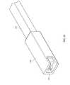
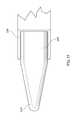
- FIG. 1is a perspective view of a an inter-body device and an inserter tube in accordance with one embodiment of the present invention
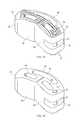
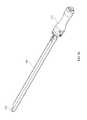
- FIG. 2is a perspective view of a an inter-body device and an inserter tube in accordance with one embodiment of the present invention
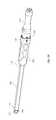
- FIG. 3is a perspective view of a an inter-body device and an inserter tube in accordance with one embodiment of the present invention
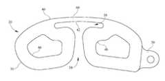
- FIG. 4is a top view of an inter-body device in accordance with one embodiment of the present invention.
- FIG. 5is a top view of an inter-body device in accordance with one embodiment of the present invention.
- FIG. 6is a top view of an inter-body device in accordance with one embodiment of the present invention.
- FIG. 7is a top view of an inter-body device in accordance with one embodiment of the present invention.
- FIG. 8is a top view of an inter-body device in accordance with one embodiment of the present invention.
- FIG. 9is a perspective view of an inter-body device in accordance with one embodiment of the present invention.
- FIG. 10is a perspective view of an inter-body device in accordance with one embodiment of the present invention.
- FIG. 11is a top view of an inter-body device in accordance with one embodiment of the present invention.
- FIG. 12is a top view of an inter-body device in accordance with one embodiment of the present invention.
- FIG. 13is a top view of an inter-body device in accordance with one embodiment of the present invention.
- FIG. 14is a perspective view of an inter-body device in accordance with one embodiment of the present invention.
- FIG. 15is a perspective view of an inter-body device in accordance with one embodiment of the present invention.
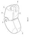
- FIG. 16is a perspective view of an inter-body device in accordance with one embodiment of the present invention.
- FIG. 17is top view of an inter-body device in accordance with one embodiment of the present invention.
- FIG. 18is a top view of an inter-body device in accordance with one embodiment of the present invention.
- FIG. 19is a top view of an inter-body device being advanced into a disc space in accordance with one embodiment of the present invention.
- FIG. 20is a perspective view of an inter-body device push rod in accordance with one embodiment of the present invention.
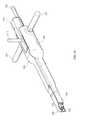
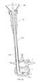
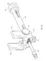
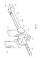
- FIG. 21is a perspective view of an insertion tool in accordance with one embodiment of the present invention.
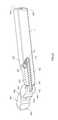
- FIG. 22is an exploded view of an insertion tool in accordance with one embodiment of the present invention.
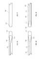
- FIG. 23is a perspective view of a trial implant in accordance with one embodiment of the present invention.
- FIG. 24is a perspective view of a bullnose and trial handle in accordance with one embodiment of the present invention.
- FIG. 25is a partial view of a bullnose and inserter in accordance with one embodiment of the present invention.
- FIG. 26is a perspective view of a trial implant in accordance with one embodiment of the present invention.
- FIG. 27is a partial view of a bullnose and inserter in accordance with one embodiment of the present invention.
- FIG. 28is an exploded view of a bullnose and trial handle in accordance with one embodiment of the present invention.
- FIG. 29is a perspective view of an assembled bullnose and trial handle in an inserter tube in accordance with one embodiment of the present invention.
- FIG. 30is a side view of an inserter tube in accordance with one embodiment of the present invention.
- FIG. 31is a side view of an inserter tube in accordance with one embodiment of the present invention.
- FIG. 32is a perspective view of a trial implant and trial handle in accordance with one embodiment of the present invention.
- FIG. 33is a side view of a trial implant in accordance with one embodiment of the present invention.
- FIG. 34is a perspective view of a trial handle in accordance with one embodiment of the present invention.
- FIG. 35is an exploded view of a trial handle in accordance with one embodiment of the present invention.
- FIG. 36is a perspective view of a trial implant and implant rod in accordance with one embodiment of the present invention.
- FIG. 37is a perspective view of a trial implant in accordance with one embodiment of the present invention.
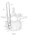
- FIG. 38is a top view of an inserter tube and trial implant advancing into a disc space in accordance with one embodiment of the present invention.
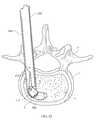
- FIG. 39is a top view of an inserter tube and trial implant advancing into a disc space in accordance with one embodiment of the present invention.
- FIG. 40is a top view of an inserter tube and trial implant advancing into a disc space in accordance with one embodiment of the present invention.
- FIG. 41is a top view of an inserter tube and trial implant advancing into a disc space in accordance with one embodiment of the present invention.
- FIG. 42is a top view of an inserter tube and trial implant advancing into a disc space in accordance with one embodiment of the present invention.
- FIG. 43is a top view of an inserter tube and trial implant advancing into a disc space in accordance with one embodiment of the present invention.
- FIG. 44is a partial side view of an inter-body device and bullnose inside an inserter tube in accordance with one embodiment of the present invention.
- FIG. 45is a partial side view of an inter-body device and bullnose inside an inserter tube in accordance with one embodiment of the present invention.
- FIG. 46is a partial top view of a bullnose in accordance with one embodiment of the present invention.
- FIG. 47is a partial bottom view of a bullnose in accordance with one embodiment of the present invention.
- FIG. 48is a partial top view of a bullnose in accordance with one embodiment of the present invention.
- FIG. 49is a partial bottom view of a bullnose in accordance with one embodiment of the present invention.
- FIG. 50is a top view of an inserter tube in a disc space, with an inter-body device and bullnose advancing into said disc space in accordance with one embodiment of the present invention
- FIG. 51is a top view of an inserter tube in a disc space, with an inter-body device and bullnose advancing into said disc space in accordance with one embodiment of the present invention
- FIG. 52is a top view of an inserter tube in a disc space, with an inter-body device and bullnose advancing into said disc space in accordance with one embodiment of the present invention
- FIG. 53is a perspective view of a box cutter in accordance with one embodiment of the present invention.
- FIG. 54is a side view of a box cutter in accordance with one embodiment of the present invention.
- FIG. 55is a side view of an inserter tube advanced into a disc space in accordance with one embodiment of the present invention.
- FIG. 56is a perspective view of a trial handle and a bullnose in accordance with one embodiment of the present invention.
- FIG. 57is a perspective view of a trial handle and a bullnose in accordance with one embodiment of the present invention.
- FIG. 58is a cross-sectional side view of a bullnose and inter-body device being advanced through an inserter tube in accordance with one embodiment of the present invention
- FIG. 59is a perspective view of an inter-body device insertion tool in accordance with one embodiment of the present invention.
- FIG. 60is a perspective view of an inter-body device insertion tool in accordance with one embodiment of the present invention.
- FIG. 61is a perspective view of a bone graft funnel secured to an inserter tube in accordance with one embodiment of the present invention.
- FIG. 62is a perspective view of a bone graft funnel in accordance with one embodiment of the present invention.
- FIG. 63is a perspective view of a bone graft funnel in accordance with one embodiment of the present invention.
- FIG. 64is an exploded perspective view of a bone graft plunger in accordance with one embodiment of the present invention.
- FIG. 65is a perspective view of a bone graft plunger in accordance with one embodiment of the present invention.
- FIG. 66is a perspective view of a bone graft plunger in accordance with one embodiment of the present invention.
- FIG. 67is a side view of a bone graft plunger in accordance with one embodiment of the present invention.
- FIG. 68is a perspective view of a bone graft plunger in accordance with one embodiment of the present invention.
- FIG. 69is a cross-sectional side view of a bone graft plunger being advanced through an inserter tube into a disc space in accordance with one embodiment of the present invention.
- FIG. 70is a side view of a bone graft plunger being advanced through an inserter tube into a disc space in accordance with one embodiment of the present invention
- FIG. 71is a cross-sectional side view of a bone graft plunger being advanced through an inserter tube in accordance with one embodiment of the present invention
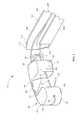
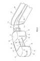
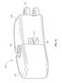
- FIG. 72is a perspective view of an extension arm in accordance with one embodiment of the present invention.
- FIG. 73is a side view of an extension arm in accordance with one embodiment of the present invention.
- FIG. 74is a perspective view of an extension arm in accordance with one embodiment of the present invention.
- FIG. 75is a perspective view of an extension arm in accordance with one embodiment of the present invention.
- FIG. 76is a perspective view of an extension arm in accordance with one embodiment of the present invention.
- FIG. 77is a perspective view of an extension arm in accordance with one embodiment of the present invention.
- FIG. 78is a perspective view of an extension arm in accordance with one embodiment of the present invention.
- FIG. 79is a perspective view of an extension arm in accordance with one embodiment of the present invention.
- FIG. 80is a perspective view of the system of the present invention in place in the environment of a human spine in accordance with one embodiment of the present invention.
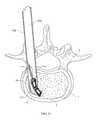
- FIGS. 50 and 55depict one example of the insertion of inter-body device 20 into a disc space 2 of a spine 1 between vertebrae 4 , and may be referred to throughout this specification for reference to the human anatomy to which the present invention is applied.
- the disc to be replaced by the inter-body device 20 of the present inventionis first removed by a surgeon performing a thorough discectomy.
- discectomytypically, it is desirable to extend the discectomy to a contralateral half of the disc space to allow placement of the longest inter-body device 20 possible and to maximize bony surface exposure for fusion to occur. If there is significant disc space 2 collapse, a complete discectomy may not be possible until disc space 2 distraction is performed utilizing one of many known in the art distraction tools.
- inter-body device 20may comprise a plurality of lobes or cans 30 , each spaced one from another and depending from a flexible bridge 60 that permits independent flexure and motion of each can 30 to facilitate entry into disc space 2 .
- Flexible bridge 60may be comprised of a memory metal such as nitinol or other flexible plastic material that has shape memory so that the overall shape of inter-body device 20 is retained once device 20 is implanted.
- each can 30includes a pair of generally parallel passageways 32 therein, through which a suture 3 may be threaded to aid in positioning of inter-body device 20 , as well as to enable retrieval device 20 should its' placement prove unsatisfactory.
- suture 3may be manipulated to aid in implant positioning by pulling on either end thereof. Once device 20 is properly positioned, suture 3 may simply be pulled through both passageways 32 and thus removed from inter-body device 20 .
- Inter-body device 20 cans 30may further comprise an upper surface 34 and a lower surface 36 that contact upper and lower surfaces of adjacent vertebrae 4 once inter-body device 20 is properly positioned in disc space 2 .
- Inter-body device 20may further comprise an anterior wall 40 that may be integral with bridge 60 , and may be generally convex in shape.
- Anterior wall 40may terminate in distal and proximal cans 30 .
- Anterior wall 40includes an interior wall portion 42 that extends between adjacent cans 30 .
- each can 30includes a posterior wall 44 that extends generally between upper 34 and lower 36 portions of cans 30 on a posterior portion thereof.
- inter-body device 20is preferably formed of a material that is durable and non-reactive.
- a wide variety of biocompatible materialsmay be utilized to manufacture the inter-body device 20 of the present invention, including but not limited to biocompatible polymers, elastomeric materials, hydrogels, hydrophilic polymers, shape memory polymers, and shape memory metals. It is understood that one of ordinary skill in the art would be aware of a variety of materials suitable for such implantation.
- inter-body device 20is comprised of a carbon fiber material while in another, device 20 is comprised of a polyetherketone (PEK) material.
- PEKpolyetherketone
- proximal can 30may include a hitch 50 , depicted in this embodiment of the invention as a generally annular protrusion extending outwardly from proximal can 30 , which may be grasped or secured to various insertion tools as will be discussed in greater detail herein below.
- a hitch 50depicted in this embodiment of the invention as a generally annular protrusion extending outwardly from proximal can 30 , which may be grasped or secured to various insertion tools as will be discussed in greater detail herein below.
- FIGS. 1-3also depict an inserter tube 100 shown with one wall removed to show the path of suture 3 through inserter tube 100 .
- Inserter tube 100comprises a pair of opposed upper and lower walls 102 , 104 and opposed medial and lateral walls 106 , 108 that define a hollow tubular member through which inter-body device 20 may be deployed.
- Inserter tube 100includes a distal end 110 wherein lateral wall 108 forms a curved portion 112 that guides the deployment of inter-body device 20 as it is advanced through inserter tube 100 .
- lateral wall 108 curved portion 112has a length greater than that of medial wall 106 to allow inter-body device 20 to curve into disc space 2 as it is advanced through inserter tube 100 .
- Cans 30 of each inter-body device 20are spaced such that a relief area 38 is defined by the void space between cans 30 .
- Relief area 38permits inter-body device 20 and cans 30 to flex and compress during insertion and placement into disc space 2 while returning to its relaxed shape once it is properly positioned.
- FIG. 2depicts an inter-body device 20 having only two cans 30 , thereby providing for a much larger relief area 38 .
- FIG. 3depicts an inter-body device 20 wherein suture 3 is knotted at a terminal end for retrieval of device 20 back through inserter tube 100 .
- FIG. 4is a top view of an embodiment of the present invention whereby each can 30 of inter-body device 20 includes an aperture 46 therein for accepting a morselized bone graft material to enhance the spinal fusion process. Additionally, as seen in FIG. 4 hitch 50 may comprise a generally annular aperture 52 therein for accepting a pin (not shown) or other instrument for inserting, retrieving and positioning inter-body device 20 in disc space 2 .
- FIGS. 5 and 6depict a further embodiment of the present invention whereby relief portion 38 of inter-body device 20 proximate interior wall 42 defines an elongated slot that enables bridge 60 to flex while each can 30 flexes independently of the other and is capable of motion in three planes.
- This feature of the inventionenables accurate positioning of device 20 in disc space 2 by allowing device 20 to deform during insertion into disc space 2 and expand back to its relaxed shape once properly inserted.
- the embodiment of the invention shown in FIG. 5depicts upper surfaces 32 having a plurality of corrugated ridges 33 thereon. Lower surfaces 34 may also include a plurality of corrugated ridges 33 to allow inter-body device 20 to engage the upper and lower surfaces of adjacent vertebrae when inserted in disc space 2 , which also assists in device 20 positioning within disc space 2 .
- FIG. 7depicts a yet further embodiment of inter-body device 20 whereby flexible bridge 60 is secured to a pair of opposed cans 30 , the proximal one of which includes a hitch 50 depending therefrom to facilitate insertion and removal.
- FIG. 8depicts a similar embodiment to that of FIG. 7 wherein flexible bridge 60 extends around can 30 posterior wall 44 to firmly secure can 30 to bridge 60 while still permitting independent movement of each can 30 .
- FIG. 9shows an additional exemplary embodiment of inter-body device 20 having a pair of spaced opposed flexible bridges 60 , each secured to a pair of spaced cans 30 providing a relatively large relief area 38 .
- a hitch 50is provided having a pair of spaced flanges 54 extending from proximal can 30 , each with an aperture 52 therein to accept a pin (not shown) for connecting inter-body device 20 to an insertion and removal tool as will be discussed in greater detail herein below.
- Inter-body device 200comprises a distal half 210 and a proximal half 220 connected by a central hinge 230 .
- Each half 210 , 220 of trial implant 200includes a passageway 232 into which a segment of flexible spine 240 is inserted.
- Flexible spine 240may be comprised of a memory metal to permit halves 210 , 200 to flex with respect to each other then return to a relaxed position.
- a hitch 50is also provided extending from proximal half 220 of trial implant 200 to facilitate insertion and removal thereof form disc space 2 .
- FIGS. 10 and 11depict central hinge 230 disposed approximately in the center of distal and proximal halves 210 , 220
- FIG. 12depicts hinge 230 disposed on the anterior edges of distal and proximal halves 210 , 220 to permit flexure in the anterior direction
- FIG. 13depicts hinge 230 disposed on the posterior edges of distal and proximal halves 210 , 220 to permit flexure in the posterior direction.
- FIG. 14depicts a further embodiment of the invention having a plurality of apertures 234 therein to accept bone graft material to aid in vertebral fusion.
- inter-body device 20 depicted in FIGS. 10-14may also be employed as trial implants, whereby they are inserted into disc space 2 prior to insertion of a permanent implant to test fit disc space 2 for proper size and positioning, and to determine that disc space 2 is properly prepared to receive inter-body device 20 .
- inter-body devices 20may be manufactured of a suitable material capable of reuse after proper sterilization, as is well known in the surgical arts.
- inter-body device 20is shown formed of a single piece of material, whereby flexible bridge 60 is integral with a pair of spaced elongated cans 30 , each having upper 34 and lower 36 surfaces with an aperture 46 therein for accepting bone graft material.
- the embodiment of the present invention depicted in FIGS. 15 and 17further comprises a plurality of ridges 33 on upper 34 and lower 36 surfaces to facilitate vertebral engagement of device 20 .
- a portion of one can 30comprises a void or slot 56 therein, that extends around an end of said can 30 and into posterior wall 44 thereof.
- a pair of opposed apertures 58communicate with slot 56 to accept a pin 59 that is secured in apertures 58 . Pin 59 can then easily be accessed by an insertion and removal tool as discussed below.
- flexible bridge 60extends outwardly towards the distal and proximal ends, respectively, of cans 30 to define a relief area 38 that permits considerable flexure and straightening of device 20 as it is deployed through inserter tube 100 .
- distal can 30may comprise a beveled distal edge portion 31 , best seen in FIGS. 15 and 16 , that facilitates smooth entry of device 20 into disc space 2 since the height of distal can 30 is slightly less than the height of inter-body device 20 along the remainder of its length.
- inter-body device 20 shown and described hereinmay be produced in a wide variety of sizes, varying in both overall length and height, as well as varying in spacing between cans 30 and bridge 60 such that the invention may be adapted for use in nearly any size disc space as required by a surgeon.
- the inter-body devices 20 described hereinmay include a plurality of radiographic markers disposed at a plurality of points in or on said inter-body devices 20 , to enable a surgeon to ensure proper placement of said devices 20 by conventional radiographic techniques.
- FIG. 19there is shown a flexible implant guide sleeve 140 that is sized to be inserted through inserter tube 100 into disc space 2 .
- inter-body device 20is carried by a distal end 142 of guide sleeve 140 until it is properly positioned in disc space 2 then guide sleeve 140 is retracted back into inserter tube 100 .
- Guide sleeve 140may advantageously be formed of a thin memory metal or equivalent flexible material capable of curving into disc space 2 .
- the relaxed shape of guide sleeve 140 distal end 142approximates that of inter-body device 20 and disc space 2 to facilitate placement of device 20 therein.
- FIG. 20depicts an inter-body device push rod 160 adapted to be inserted into the interior of inserter tube 100 , having a clasp 162 at a distal end 164 thereof.
- Clasp 162may be actuated by known-in-the art means to engage and release a pin 59 of an inter-body device 20 , for example the device 20 depicted in FIG. 15 .
- Distal end 164 of push rod 160may be sized to fit into slot 56 of inter-body device 20 , thereby enabling device 20 to rotate into disc space 2 before being release by disengagement of clasp 162 .
- Insertion tool 300comprises an elongated central body 310 having a handle 312 secured thereto and extending upwardly therefrom, and a lock button 314 that is inserted through an aperture 316 in an upper surface of central body 310 .
- Central body 310further includes a channel 318 that extends longitudinally through central body 310 , shaped to accept an elongated shaft 320 having a clasp 322 at a distal end 324 thereof for engaging an inter-body device 20 .
- Shaft 320further comprises a pair of spaced apertures 326 therethrough that align with a complementary pair of spaced apertures 330 in central body 310 , and into which a pair of locking pins 328 are inserted to secure shaft 320 into central body 310 .
- Insertion tool 300further comprises a stationary member 340 that includes a handle 342 secured thereto and extending outwardly therefrom, and an elongated slot 344 that is shaped to engage elongated central body 310 .
- Stationary member 340comprises a distal tip 346 shaped to direct an inter-body device 20 into a disc space, as well as an elongated groove 348 in a portion thereof.
- Central body 310fits closely into slot 344 of stationary member 340 , and is slidable therein to enable central body 310 to be advanced forward such that clasp 22 extends into disc space 2 to position inter-body device 2 .
- Insertion tool 300further comprises a sliding member 360 , having a handle 362 extending therefrom and including a tongue 364 extending longitudinally on a portion of sliding member 360 that engages groove 348 of stationary member 340 .
- Sliding member 360further comprises a distal tip 366 that is generally flat.
- sliding member 360 and stationary member 340form a channel into which an inter-body device 20 may be inserted, secured by clasp 322 of central body 310 shaft 220 .
- Sliding member 360is capable of moving forward relative to stationary member 340 , thereby enabling distal tip 366 to enter and distract disc space 2 to facilitate device 20 delivery.
- stationary member 340 and central body 310are also inserted into disc space 2 for delivery of inter-body device 20 .
- This feature of the instant inventionprovides an insertion tool 300 that assists in disc space distraction for ease of implant insertion.
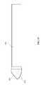
- the present inventionfurther comprises a trial implant 400 for determining the proper size of a permanent inter-body device 20 to be deployed, having a distal end 402 and a proximal end 404 secured together via a central hinge 406 that enables ends 402 , 404 to rotate in a single plane relative to each other.
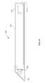
- Trial implant 400is shaped to generally conform to the shape of inter-body device 20 that will be deployed for permanent use in disc space 2 .
- Proximal end 404 of trial implant 400includes a slot 408 therein, and a pin 410 secured transversely to slot 408 for securing trial implant 400 in an articulating fashion to a trial implant rod 420 .
- Trial implant rod 420comprises an elongated body 421 terminating in a pair of spaced distal tips 422 that abut trial implant 400 at their distal ends.
- Trial implant rodfurther comprises a pin hinge 424 that extends through and is secured to both spaced distal tips 422 and a proximal end 426 having a threaded aperture therein for engagement with a trial implant insertion tool.
- An articulating arm 430having an aperture at a distal end 432 thereof is rotatably secured to pin 410 of trial implant 400 .
- Articulating arm 430further comprises a proximal end 434 having a slot 436 therein that is engaged by hinge pin 424 of implant rod 420 so that articulating arm 430 is capable of both rotational and longitudinal movement with respect to implant rod 420 . Furthermore, since trial implant 400 rotates around pin 410 , both implant 400 and articulating arm 430 are capable of rotational motion with respect to implant rod 420 .
- FIG. 32depicts trial implant 400 and implant rod 420 secured to an insertion tool 500 having a trial handle 510 secured to a threaded shaft 502 .
- trial handle 510is designed to connect to a plurality of components of the present invention, as will be discussed further herein below.
- FIG. 36depicts an alternative embodiment of trial implant rod 420 wherein distal tips 422 include hinge 424 at a distal portion thereof such that articulating arm 430 extends outwardly toward trial implant 400 .
- trial implants 400may further include a flexible spine 412 inside distal and proximal ends 402 , 404 , similar to those embodiments shown in FIGS. 10-14 .
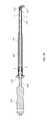
- FIG. 24depicts a trial handle 510 secured to a bullnose 600 designed to aid in distraction of disc space 2 as well as insertion of inter-body devices 20 therein.
- Bullnose 600comprises an elongated shaft 602 capable of engaging and being secured to handle 510 at a proximal end 604 thereof, and a distal end 606 having a tapered distal tip 610 thereon, for inserting into and distracting disc space 2 .
- FIG. 25depicts bullnose 600 distal tip 610 exiting distal end 110 of inserter tube 100 .
- FIGS. 26-29depict an alternative embodiment of bullnose 600 utilized for inter-body device 20 insertion having a blunt distal tip 610 at distal end 606 .
- Shaft 602includes a suture 3 guide groove 612 along a substantial portion thereof that terminates in a wide groove end 614 proximate distal end 606 of bullnose 600 .
- Guide groove 612provides a space in which suture 3 is disposed when bullnose 600 is inserted through inserter tube 100 , as shown in FIG. 29 .
- Bullnose 600 proximal end 604further includes an annular groove 616 that is engaged by a latch (such as a pin or spring-loaded ball, not shown) interior to handle 510 .
- suture 3may be secured to inter-body device 20 as shown in FIGS. 1-3 and may ride in groove 612 of bullnose 600 as it is advanced through inserter tube 100 into disc space 2 .
- Handle 510includes a distal end 512 having an aperture 514 therein for engaging a proximal end 604 of bullnose 600 .
- a locking flange 520is also disposed on distal end 512 of handle 510 for engaging a complementary flange of, for example, inserter tube 100 .
- Handle 510may also include lock 524 and unlock 522 marks on an exterior surface thereof indicating that inserter tube 100 is locked onto handle 512 when a corresponding mark on tube 100 is aligned with lock mark 524 , and alternatively unlocked with a corresponding mark on tube 100 is aligned with unlock mark 522 .
- Handle 522may include a release button 530 that is biased by spring 532 to engage (or disengage) a locking pin 516 extending through the distal end 512 thereof, for releasing bullnose 600 from engagement with handle 510 .
- FIGS. 29-31depict one exemplary embodiment of inserter tube 100 and its engagement with handle 510 .
- Inserter tube 100includes a distal end 100 terminating in a curved portion 112 and a proximal end 114 terminating in a hollow handle 120 that communicates with tube 100 , said handle 120 having a locking flange 122 on an interior circumference thereof that engages complementary locking flange 520 of trial handle 510 .
- Inserter tube 100 handle 120may also include an alignment arrow 124 that, when aligned with one of the lock/unlock markings 524 , 522 of handle 510 indicate that locking flange 122 of inserter tube 100 is engaged or disengaged with locking flange 520 of handle 110 .
- inserter tube handle 120may comprise a small groove in a proximal edge thereof to accommodate suture 3 as it exits handle 120 when inter-body device 20 is being deployed.
- FIG. 29additionally shows bullnose 600 inserted into inserter tube 100 and extending through distal end 110 thereof.
- bullnose 600may be secured to handle 510 thence inserted into inserter tube 100 , which is then locked onto handle 510 .
- bullnose 600may then be inserted to an exact depth into disc space 2 necessary for suitable placement of inter-body device 2 .
- inserter tube 100may be provided with a plurality of depth markings along the exterior surfaces thereof (for example on upper and lower walls 102 , 104 and on medial and lateral walls 106 , 108 ) to assist a surgeon in proper placement of inserter tube 100 , as will be discussed in further detail herein below.
- FIGS. 38-43depict the deployment of trial implant 400 through inserter tube 100 into disc space 2 .
- inserter tube 100 and concomitant bullnose 600are inserted into disc space 2 through an annulotomy as far laterally in the disc space as possible.
- This first stepis typically practiced with bullnose 600 having a tapered tip 610 to aid in disc space distraction.
- the tapered tip 610extends approximately 15 mm past beyond the distal end 110 curved tip 112 of inserter tube 100 .
- a surgeonmay note the depth of the inserter tube in the annulotomy at this stage of the procedure.
- a blunt tip 610 bullnoseis assembled to trail handle 510 and inserter tube 100 and reinserted in disc space 2
- the blunt tip 610extends approximately 10 mm past beyond the distal end 110 curved tip 112 of inserter tube 100 .
- the blunt tip 610 and concomitant inserter tube 100are advanced into disc space 2 until distal tip 610 of bullnose 600 touches the anterior annulus 5 of disc space 2 .
- bullnose 600may be withdrawn and inserter tube 100 locked into place, as will be discussed further herein below.
- a trial implant 400is now secured to trial handle 510 and is advanced into disc space 2 , as shown sequentially in FIGS. 38-43 .
- the ability of trial implant 400 to articulate coupled with the curved portion 112 of inserter tube 100enable accurate and easy placement of trial implant 400 in disc space 2 .
- differing lengths and heights of trial implants 400may be employed to determine the proper size inter-body device 20 to be used.
- the longest trial implant 400 that can be successfully deployed in disc space 2will determine the length of inter-body device 20 to be used.
- the height of a distractor used to distract the disc spacewill determine the height of the inter-body device 20 to be deployed.
- bullnose 600comprises a single longitudinal suture guide groove 612 and wide groove end on one side of bullnose 600 .
- FIG. 44depcits distal tip 610 advancing device 20 through inserter tube 100 until it is properly positioned in disc space 2 .
- FIGS. 45 , 48 and 49depict a bullnose 600 having a longitudinal suture guide groove 612 and wide groove end on two sides of bullnose 600 , whereby suture 3 is routed both above and below bullnose 600 shaft 602 , as best seen in FIG. 45 .
- This embodiment of the inventionfacilitates manipulation and placement of inter-body device 20 in disc space 2 .
- FIGS. 50-52there is depicted the deployment of inter-body device 2 through inserter tube 100 into disc space 2 .
- Apertures 46 of cans 30may be filled with morselized bone graft material prior to inserting inter-body device 20 into inserter tube 100 .
- a suture 3is secured to hitch 50 of device 20 prior to insertion in inserter tube 100 as well.
- the suture guide groove 612 of bullnose 600may also be aligned with the groove in inserter tube handle 120 to provide clearance for suture 3 .
- the looped suture 3 shown in FIGS. 50-52is disposed in groove 612 and bullnose 600 is then inserted into inserter tube 100 , pushing inter-body device 20 into place as it advances into tube.
- blunt distal tip 610 bullnose 600is used for insertion of inter-body device 20 .
- radiographical techniquesmay be used to verify the positioning of inter-body device 20 , whereupon suture 3 is removed, as is bullnose 600 and concomitant handle 510 .
- Inserter tube 100may remain in place in disc space 2 for application of bone graft material as described below.
- FIGS. 53 and 54depict a box cutter 300 used to shave posterior endplates of adjacent vertebrae 4 in preparation for inter-body device 20 deployment.
- Box cutter 700comprises a central shaft 702 secured to a handle 704 at a proximal end thereof.
- Handle 704may have an option slap hammer flange 706 at a proximal end thereof for attaching a known-in-the art slap-hammer device to aid in use of box cutter 700 .
- a detachable head 708is secured to shaft 702 at a distal end thereof, having a tapered distal tip 710 to facilitate distraction as head 708 enters the disc space 2 .
- Head 708may be provided in varying widths and heights to accommodate variable spinal geometry, and further may be provided with depth markers (not shown) along the exterior surfaces thereof to enable a surgeon to determine how far distal tip 710 advances into disc space 2 .
- box cutter head 708 heightmay be provided by a marking on the surface thereof. Additionally, box cutter head 708 may include exterior markings indicating the distance from distal tip 710 .
- Box cutter 700further comprises a pair of spaced cutting edges 714 that facilitate the shaving of the posterior endplates with box cutter 700 .
- box cutter 700 head 708is selected having an appropriate width for a given application, and the posterior endplates of adjacent vertebrae 4 are shaved by advancing cutting edges 714 into disc space 2 , utilizing a slap-hammer attachment if necessary.
- FIGS. 55-58depict an alternative embodiment of the inserter tube 100 of the instant invention wherein the proximal end 114 is slightly wider than distal end 110 and wherein no handle is present.
- FIG. 56depicts an alternative embodiment of bullnose 600 having a proximal end 604 that includes a threaded shaft 618 for engaging a handle 510 , as well as a threaded stop 620 that is rotatable along threaded shaft 618 that abuts distal end 114 of inserter tube 100 when bullnose 600 is inserted therein.
- FIG. 56further depicts a conventional “slap-hammer” 6 device secured to handle 510 to apply additional longitudinal force to bullnose 600 where necessary.
- FIG. 57is a view of bullnose 600 from the opposite side as FIG. 56 , depicting a second suture guide groove 612 extending longitudinally into distal tip 610 of bullnose 600 for positive placement of suture 3 .
- FIG. 58is a cross-sectional view of bullnose 600 deploying inter-body device 20 through inserter tube 100 , wherein suture 3 is guided in grooves 112 both above and below bullnose 600 , as suture 3 loops through hitch 50 of inter-body device 20 . This feature of the invention further aids in positioning of implants as they are deployed into disc space 20 .
- FIGS. 59 and 60depict two inter-body device 20 insertion and retrieval tools 750 , each having a distal end 752 having a pair of spaced furcations 754 extending therefrom to engage pin 59 of inter-body device 20 , or a similar hitch 50 .
- furcations 754are spaced to snap-fit onto pin 59 of hitch 50 .
- a longitudinally slidable sleeve 756is provided over distal end 752 of tool 750 that forces furcations 754 together to grasp pin 59 as sleeve 756 is advanced toward distal end 752 .
- FIGS. 61 and 62depict a bone graft funnel 800 that is operatively secured to inserter tube 100 handle 100 having an aperture 802 therein for supplying bone graft material through inserter tube 100 to disc space 2 , as well as a flat edge 804 for ease of use, thereby facilitating use of bone graft funnel with other instruments or structures employed in spinal surgery.
- a locking flange 806is provided on one edge thereof for engaging a complementary flange on inserter tube 100 handle 120 .
- FIG. 64depicts a bone graft plunger 820 designed for use with bone graft funnel 800 and inserter tube 100 , having an angled plunger tip 822 on a distal end thereof.
- Angled plunger tip 822may be formed of, for example, a flexible material such as a silastic elastomer that enables plunger tip 822 to flex as it extends through inserter tube 100 .
- plunger tip 822is disposable after each use.
- angled tip 822is sized to be slightly larger than the interior profile of inserter tube 100 to tightly engage inserter tube 100 and enable angled tip 822 to force all the bone graft material deposited in inserter tube 100 into disc space 2 .
- Bone graft plunger 820further comprises a central shaft 824 having a distal end 826 that is shaped to snap-fit onto a complementary aperture 828 of angled tip 822 , thereby securing tip 822 to shaft 824 .
- a proximal end 830 of shaft 824may include a threaded aperture 832 for securing bone graft plunger to a handle 510 .
- plunger tip 822is be comprised of an elastomeric material, making it both flexible and disposable after use
- plunger shaft 824may be comprised of elastomer, but may also be produced from more durable alloys for repeated use after sterilization.
- FIG. 66depicts an alternative embodiment of bone graft plunger 820 that includes an elongated angled flexible tip 822 (shown in its relaxed state) that is secured to a plunger shaft 824 .
- This embodiment of the inventionenables bone graft material to be deposited further into disc space 2 since plunger 820 assumes a relaxed shape that approximates that of anterior disc space 2 .
- FIGS. 67 and 68show an alternative bone graft plunger 820 that is a single-piece plunger having an integral angled tip 822 and plunger shaft 824 .
- Bone graft plunger 820 angled tip 822may include a curved surface 823 designed to push bone graft material through complementary curved portion 112 of inserter tube 100 .
- Plungers 820 constructed in accordance with this embodiment of the present inventioncan be manufactured of an elastomer or metal alloy without departing from the scope of the present invention.
- FIG. 69is a cross-section of bone graft funnel 800 , plunger 820 , and inserter tube 100 in operation.
- Funnel 800is secured to inserter tube 100 handle 120 and provides a convenient mechanism for depositing bone graft material 7 into inserter tube 100 .
- Plunger 820is then inserted into aperture 802 , and through handle 120 into inserter tube 100 , thereby forcing all bone graft material 7 deposited therein into inserter tube 100 and disc space 2 .
- Funnel 800is then removed from handle 120 and plunger 820 is once again used to force the remaining bone graft material in inserter tube 100 into disc space 2 .
- Flexible angled tip 822enables plunger 820 to curve into disc space 2 as it is advanced, thereby providing superior delivery of bone graft material 7 .
- FIGS. 70 and 71depict an alternative embodiment of bone graft plunger 820 , wherein angled tip 822 and shaft 824 are comprised of a single piece of memory metal that is curved to approximate the curvature of an anterior portion of disc space 2 in its relaxed shape.
- bone graft plunger 820is straightened to insert its distal tip 822 into funnel 800 and inserter tube 100 , and it assumes its curved or relaxed shape when inserted into disc space 2 .
- extension arm 900is depicted for securing various components of the present system 10 to a plurality of pedicle screws 9 that are secured to a human spine by known-in-the-art surgical techniques.
- extension arm 900comprises an arm body 902 that engages a central threaded rod 910 having a proximal end that may be turned by, for example, a wrench, nut driver, or like mechanical device.
- Rod 910also includes a distal end 914 , which is shown in the present embodiment having a plurality of helical threads thereon for engaging a pedicle screw having complementary threads therein.
- An adjustable clamp 920is secured to extension arm body 902 by a conventional adjustment knob 921 and concomitant threaded member (not shown).
- Clamp 920includes a pair of spaced clamp arms 922 extending outwardly from body 902 that are adjustable with respect to one another by conventional means, for example a clamp adjustment knob 924 secured to a threaded member 926 , that engages complementary threads 928 in each clamp arm.
- Extension arm 900is secured to a complementary pedicle screw by rotating central rod 910 to engage distal end 914 with the pedicle screw. Clamp 920 is then adjusted to position arms 922 to secure, for example, inserter tube 100 to extension arm 900 in a precise location for delivery of inter-body device 20 .
- FIGS. 74 and 75depict additional embodiments of extension arm 900 that include an extension arm body 902 that has a distal end 914 having a transverse pin 906 secured thereto for engaging a complementary hook of a pedicle screw (not shown).
- FIGS. 76 and 78depict an alternative embodiment of extension arm 900 having a body 902 that is shaped like an elongated channel, having a pair of spaced edges 907 along its length.
- Distal end 914includes a cut-out portion 916 that engages a head of a pedicle screw 9 , as shown in FIG. 78 .
- Clamp 920is secured to a clamp guide 930 that includes a pair of spaced arms 932 , each having a groove 934 therein for engaging edges 907 of extension arm 900 body 902 .
- clamp guide 930 arms 932slide onto body 902 edges 907 , thereby providing a clamp guide 930 and claim 920 that is slidable along the length of extension arm body 902 .
- FIGS. 77 and 79depict a similar extension arm embodiment to those shown in FIGS. 76 and 78 , except that distal end 914 includes a vertical pin 918 that engages an aperture in pedicle screw 9 , as best seen in FIG. 79 .
- FIG. 80depicts the system 10 of the present invention secured to vertebrae 4 of spine 1 in an exemplary fashion.
- a plurality of pedicle screwsare secured to spine 1 in a conventional fashion, as is known to one of ordinary skill in the art.
- Extension arm 900is secured to pedicle screw 9 at its distal end 914 .
- Clamp 920 of extension arm 900is positioned via clamp guide 930 to engage handle 120 of inserter tube 100 .
- Inserter tube 100is positioned to be inserted through the annulotomy into disc space 2 .
- trial handle 510is secured to bullnose 600 and inserted through inserter tube 100 .
- the present system 10 and the components thereofmay be employed by a surgeon to effect disc replacement in the following fashion.
- a surgeonmakes a longitudinal midline incision in the area of pathology, through skin, subcutaneous tissue and fascia. Radiologic confirmation of vertebral level is then obtained through conventional radiographic techniques.
- the lumbar spineis exposed through subperiosteal dissection, extending exposure only to the base of the transverse processes to permit identification of the entry points for insertion of pedicle screws 9 .
- TLIFtransforaminal lumbar inter-body fusion
- Pedicle screwsare then applied in the conventional manner, as is known to one of ordinary skill in the art.
- a total ipsilateral facetectomyis performed, using an osteotome or drill. Additional bony removal may be carried out using a Kerrison Rongeur or drill to create a bigger space for insertion of appropriate sized implants and instruments. At this point, a surgeon may perform any additional neural decompression, if the determination is made that the particular case requires it. The posterolateral corner of the annulus is exposed maximally to allow an annulotomy as far lateral as possible. Next, a 1 cm-wide annulotomy incision is made.
- a thorough discectomyis performed. It is desirable in one embodiment of the present invention to extend the discectomy to the contralateral half of the disc space to allow for placement of the longest inter-body device 20 possible and to maximize bony surface exposure for fusion to occur. If there is significant disc space 2 collapse, a complete discectomy may not be possible until disc space 2 distraction is complete.
- the surgeondistracts the disc space sequentially with conventional distraction instruments, for example distractors ranging in height from 6 mm to 16 mm, until a snug fit is achieved.
- the surgeonmay note the insertion depth and the height of the distractor used since the insertion depth gauges the depth of disc space 2 .
- the height of the distractor employed in this stepwill determine the height chosen for the box cutter 700 , bullnoses 600 , inserter tube 100 , trial implants 400 , and inter-body device 20 .
- a surgeonmay apply a conventional contralateral distractor to maintain disc height and perform any additional discectomy, as necessary to prepare disc space 2 .
- a surgeonmay employ a standard Penfield Elevator to palpate the vertebral endplate and then feel the anterior edge of the vertebral body. Once the anterior edge is felt and the Penfield Elevator dips, then adequate discectomy up to the anterior annulus has been achieved.
- box cutter 700is inserted to shave the posterior endplate by utilizing a box cutter head of the same size as the tallest distractor used to achieve a snug fit as discussed above.
- Box cutter head 708 heightmay be provided on the surface thereof. It also has markings indicating the distance from distal tip 710 . The surgeon then decorticates the remaining endplate surfaces of the superior and inferior vertebral bodies to enhance formation of bony fusion.
- the surgeonsecures the extension arm 900 loosely to the inferior pedicle screw 9 .
- Trial handle 510is next secured to an appropriately sized bullnose 610 , with a tapered distal tip 610 and this assembly is inserted into an identically sized inserter tube 100 .
- Bullnose 600 and inserter tube 100 heightsmay marked on the instruments, as necessary.
- the assembled bullnose 600 and inserter tube 100is advanced into disc space 2 through the annulotomy, by directing inserter tube 100 distal end 100 five to ten degrees laterally.
- the assembly orientationis then slowly manipulated to 0 degrees in the sagittal plane, keeping inserter tube 100 as far lateral in disc space 2 as possible.
- bullnose 600is inserted into inserter tube 100 by engaging inserter tube handle 120 with trial handle 510 .
- bullnose 600 having a tapered distal tip 610extends 15 mm beyond the inserter tube distal aperture 110 .
- bullnose 600 having a blunt distal tip 610extends only 10 mm beyond inserter tube 100 distal tip 110 .
- the surgeonadvances the handle 510 , bullnose 600 , and inserter tube 100 assembly deeper into disc space 2 until bullnose 600 distal end 610 touches the anterior annulus thereof.
- the surgeonsecures inserter tube 100 handle 120 to extension arm 900 and extension arm 900 distal end 914 is secured tightly to pedicle screw 9 .
- the surgeoncan remove bullnose 600 , while remembering that in this position, there is 10 mm of free space between inserter tube 100 distal tip 110 and the anterior annulus of disc space 2 , to allow smooth deployment of the bullnose 600 having a blunt distal tip 610 and inter-body device 20 into the anterior disc space 2 .
- the surgeonassembles handle 510 to the determined trial implant 400 height size.
- Each trial implant 400may be marked with its length and height to facilitate assembly in the operating room.
- the surgeonnext sequentially attempts to deploy three different trial implant 400 lengths (of the chosen trial implant 400 height), starting with the shortest (for example, 20 mm), then with an intermediate (for example, 25 mm) to the longest (for example, 30 mm). Saline may be used to lubricate the inserter for easier deployment.
- the longest trial implant 400 length that can be successfully deployed into disc space 2determines the inter-body device length to be used. After radiologic confirmation of satisfactory trial implant 400 position within disc space 2 , remove trial implant 400 from disc space 2 and inserter tube 100 .
- the surgeonsecures handle 510 to the previously determined bullnose 600 height.
- bullnose 600 having blunt distal end 610will be employed to push inter-body device 20 through inserter tube 100 .
- Each inter-body device 20may be marked with its height and length to facilitate assembly.
- the inter-body deviceshould be visually inspected by the surgeon for any damage.
- a standard No. 2 suture 3may be looped through hitch 50 of inter-body device 20 . Suture 3 will allow the inter-body device 20 to be retrieved, if necessary, before complete passage through inserter tube 100 . If inter-body device 20 is retrieved it should again be visually inspected for any damage.
- the surgeonnext fills apertures 46 within the inter-body device 20 cans 30 with morselized bone graft material.
- the relief area 38 between cans 30 and anterior wall 40should not be filled to permit inter-body device 20 bridge 60 and cans 30 to flex. Doing so may affect the proper deployment of inter-body device 20 through inserter tube 100 and disc space 2 .
- Inserter tube 100medial and lateral sides may be labeled on the instrument for ease of insertion.
- the surgeonpositions looped suture 3 into the suture groove in inserter tube 100 handle 120 .
- the groove in inserter tube 100 handle 120should align with suture guide groove 612 in bullnose 600 . This prevents suture 3 from being caught between the sliding surfaces of bullnose 600 and the interior wall of inserter tube 100 .
- the surgeonnext advances the inter-body device 20 along inserter tube 100 and into anterior disc space 2 .
- Salinemay be used to lubricate inserter tube 100 for easier deployment. Once inserted, the surgeon verifies device 20 position by conventional radiography.
- Inserter tube 100is next unlocked from extension arm 900 and handle 510 , and bullnose 600 and inserter tube 100 assembly is withdrawn from disc space by approximately 10 mm in preparation for application of bone graft material. A slap hammer may be used to aid withdrawal. This assembly is then secured back to extension arm 900 utilizing clamp 920 .
- Bone graft funnel 800is then placed on the proximal end of inserter tube 100 handle 120 .
- the surgeonthen assembles the appropriate size bone graft plunger 820 tip 822 to handle 510 .
- each plunger tip 822is marked with its height.
- the surgeondeposits morselized bone graft material 7 into bone graft funnel 800 , and pushes it down inserter tube 100 using the bone graft plunger 820 .
- the bone graft funnel 800is disconnected from inserter tube handle 120 .
- the bone graft material 7may then be pushed further into disc space 2 using bone graft plunger 820 again.
- surgeonmay remove the bone graft plunger 820 , disconnect extension arm 900 from pedicle screw 9 , and remove extension arm 900 and inserter tube 100 as an assembled unit to complete the procedure.
Landscapes
- Health & Medical Sciences (AREA)
- Orthopedic Medicine & Surgery (AREA)
- Engineering & Computer Science (AREA)
- Biomedical Technology (AREA)
- Transplantation (AREA)
- Life Sciences & Earth Sciences (AREA)
- Heart & Thoracic Surgery (AREA)
- Public Health (AREA)
- Oral & Maxillofacial Surgery (AREA)
- General Health & Medical Sciences (AREA)
- Veterinary Medicine (AREA)
- Animal Behavior & Ethology (AREA)
- Neurology (AREA)
- Vascular Medicine (AREA)
- Cardiology (AREA)
- Physical Education & Sports Medicine (AREA)
- Surgery (AREA)
- Dentistry (AREA)
- Nuclear Medicine, Radiotherapy & Molecular Imaging (AREA)
- Medical Informatics (AREA)
- Molecular Biology (AREA)
- Prostheses (AREA)
- Surgical Instruments (AREA)
Abstract
Description
Claims (17)
Priority Applications (3)
| Application Number | Priority Date | Filing Date | Title |
|---|---|---|---|
| US12/833,352US8828082B2 (en) | 2009-07-09 | 2010-07-09 | Inter-body implant |
| US14/331,793US9877844B2 (en) | 2009-07-09 | 2014-07-15 | Inter-body implant |
| US15/869,219US10806594B2 (en) | 2009-07-09 | 2018-01-12 | Inter-body implant |
Applications Claiming Priority (2)
| Application Number | Priority Date | Filing Date | Title |
|---|---|---|---|
| US22433309P | 2009-07-09 | 2009-07-09 | |
| US12/833,352US8828082B2 (en) | 2009-07-09 | 2010-07-09 | Inter-body implant |
Related Child Applications (1)
| Application Number | Title | Priority Date | Filing Date |
|---|---|---|---|
| US14/331,793DivisionUS9877844B2 (en) | 2009-07-09 | 2014-07-15 | Inter-body implant |
Publications (2)
| Publication Number | Publication Date |
|---|---|
| US20110009970A1 US20110009970A1 (en) | 2011-01-13 |
| US8828082B2true US8828082B2 (en) | 2014-09-09 |
Family
ID=43033115
Family Applications (5)
| Application Number | Title | Priority Date | Filing Date |
|---|---|---|---|
| US12/833,352Active2031-02-02US8828082B2 (en) | 2009-07-09 | 2010-07-09 | Inter-body implant |
| US12/833,342ActiveUS9814599B2 (en) | 2009-07-09 | 2010-07-09 | Inter-body implantation system and method |
| US14/331,793Active2030-07-25US9877844B2 (en) | 2009-07-09 | 2014-07-15 | Inter-body implant |
| US15/810,829Active2031-03-18US10835386B2 (en) | 2009-07-09 | 2017-11-13 | Inter-body implantation system and method |
| US15/869,219Active2030-10-11US10806594B2 (en) | 2009-07-09 | 2018-01-12 | Inter-body implant |
Family Applications After (4)
| Application Number | Title | Priority Date | Filing Date |
|---|---|---|---|
| US12/833,342ActiveUS9814599B2 (en) | 2009-07-09 | 2010-07-09 | Inter-body implantation system and method |
| US14/331,793Active2030-07-25US9877844B2 (en) | 2009-07-09 | 2014-07-15 | Inter-body implant |
| US15/810,829Active2031-03-18US10835386B2 (en) | 2009-07-09 | 2017-11-13 | Inter-body implantation system and method |
| US15/869,219Active2030-10-11US10806594B2 (en) | 2009-07-09 | 2018-01-12 | Inter-body implant |
Country Status (6)
| Country | Link |
|---|---|
| US (5) | US8828082B2 (en) |
| EP (2) | EP2451404B1 (en) |
| JP (2) | JP5699143B2 (en) |
| BR (2) | BRPI1012883B8 (en) |
| ES (2) | ES2563172T3 (en) |
| WO (2) | WO2011006081A1 (en) |
Cited By (4)
| Publication number | Priority date | Publication date | Assignee | Title |
|---|---|---|---|---|
| US20170119548A1 (en)* | 2015-11-03 | 2017-05-04 | Warsaw Orthopedic, Inc. | Spinal implant inserter utilizing offset striking arms |
| US10070971B2 (en)* | 2016-01-22 | 2018-09-11 | Warsaw Orthopedic, Inc. | Surgical instrument and method |
| US20210236300A1 (en)* | 2020-02-05 | 2021-08-05 | K2M, Inc. | Flexible Interbody Implant |
| US11517450B2 (en) | 2019-06-27 | 2022-12-06 | Pioneer Surgical Technology, Inc. | Intervertebral implant inserter tool |
Families Citing this family (89)
| Publication number | Priority date | Publication date | Assignee | Title |
|---|---|---|---|---|
| US8236029B2 (en) | 2004-08-11 | 2012-08-07 | Nlt Spine Ltd. | Devices for introduction into a body via a substantially straight conduit to for a predefined curved configuration, and methods employing such devices |
| US20060036241A1 (en) | 2004-08-11 | 2006-02-16 | Tzony Siegal | Spinal surgery system and method |
| WO2006034436A2 (en) | 2004-09-21 | 2006-03-30 | Stout Medical Group, L.P. | Expandable support device and method of use |
| WO2006058221A2 (en) | 2004-11-24 | 2006-06-01 | Abdou Samy M | Devices and methods for inter-vertebral orthopedic device placement |
| EP2023864B1 (en) | 2006-05-01 | 2019-07-10 | Stout Medical Group, L.P. | Expandable support device |
| WO2008070863A2 (en) | 2006-12-07 | 2008-06-12 | Interventional Spine, Inc. | Intervertebral implant |
| EP2237748B1 (en) | 2008-01-17 | 2012-09-05 | Synthes GmbH | An expandable intervertebral implant |
| US8936641B2 (en) | 2008-04-05 | 2015-01-20 | DePuy Synthes Products, LLC | Expandable intervertebral implant |
| CA2731351A1 (en)* | 2008-07-27 | 2010-02-04 | Nonlinear Technologies Ltd. | Tool and corresponding method for removal of material from within a body |
| US8328812B2 (en) | 2008-07-27 | 2012-12-11 | NLT-Spine Ltd. | Tool and corresponding method for removal of material from within a body |
| US8147554B2 (en)* | 2008-10-13 | 2012-04-03 | Globus Medical, Inc. | Intervertebral spacer |
| US8545566B2 (en)* | 2008-10-13 | 2013-10-01 | Globus Medical, Inc. | Articulating spacer |
| WO2010056895A1 (en) | 2008-11-12 | 2010-05-20 | Stout Medical Group, L.P. | Fixation device and method |
| US20100211176A1 (en) | 2008-11-12 | 2010-08-19 | Stout Medical Group, L.P. | Fixation device and method |
| US9526620B2 (en) | 2009-03-30 | 2016-12-27 | DePuy Synthes Products, Inc. | Zero profile spinal fusion cage |
| US9642722B2 (en)* | 2009-07-02 | 2017-05-09 | Atlas Spine, Inc. | Intervertebral expandable spacer |
| ES2563172T3 (en) | 2009-07-09 | 2016-03-11 | R Tree Innovations, Llc | Flexible intersomatic implant |
| US9028553B2 (en) | 2009-11-05 | 2015-05-12 | DePuy Synthes Products, Inc. | Self-pivoting spinal implant and associated instrumentation |
| US8764806B2 (en) | 2009-12-07 | 2014-07-01 | Samy Abdou | Devices and methods for minimally invasive spinal stabilization and instrumentation |
| US9393129B2 (en) | 2009-12-10 | 2016-07-19 | DePuy Synthes Products, Inc. | Bellows-like expandable interbody fusion cage |
| US9265622B2 (en)* | 2010-03-22 | 2016-02-23 | Amendia, Inc. | Percutaneous arthrodesis method and system |
| WO2011149557A1 (en)* | 2010-05-27 | 2011-12-01 | Stout Medical Group, L.P. | Support device and method for use |
| US9907560B2 (en) | 2010-06-24 | 2018-03-06 | DePuy Synthes Products, Inc. | Flexible vertebral body shavers |
| US8979860B2 (en) | 2010-06-24 | 2015-03-17 | DePuy Synthes Products. LLC | Enhanced cage insertion device |
| US8623091B2 (en) | 2010-06-29 | 2014-01-07 | DePuy Synthes Products, LLC | Distractible intervertebral implant |
| CN103096843A (en) | 2010-07-21 | 2013-05-08 | Nlt脊椎有限公司 | Spinal surgery implants and delivery system |
| EP2608747A4 (en) | 2010-08-24 | 2015-02-11 | Flexmedex Llc | Support device and method for use |
| US9402732B2 (en) | 2010-10-11 | 2016-08-02 | DePuy Synthes Products, Inc. | Expandable interspinous process spacer implant |
| US8906092B2 (en)* | 2011-01-24 | 2014-12-09 | Samy Abdou | Spinous process fixation devices and methods of use |
| WO2012112592A2 (en)* | 2011-02-14 | 2012-08-23 | Medicinelodge, Inc Dba Imds Co-Innovation | Expandable intervertebral spacer |
| EP3485851B1 (en) | 2011-03-22 | 2021-08-25 | DePuy Synthes Products, LLC | Universal trial for lateral cages |
| CN103648415A (en) | 2011-05-12 | 2014-03-19 | Nlt脊椎有限公司 | Tissue disruption device and corresponding methods |
| EP2747682A4 (en) | 2011-08-23 | 2015-01-21 | Flexmedex Llc | Tissue removal device and method |
| EP2758008B1 (en)* | 2011-09-20 | 2019-09-11 | The University of Toledo | Expandable inter-vertebral cage |
| US8845728B1 (en) | 2011-09-23 | 2014-09-30 | Samy Abdou | Spinal fixation devices and methods of use |
| FR2981262B1 (en)* | 2011-10-14 | 2014-09-19 | Pierre Roussouly | INTERSOMATIC IMPLANT |
| US9198765B1 (en) | 2011-10-31 | 2015-12-01 | Nuvasive, Inc. | Expandable spinal fusion implants and related methods |
| US20130110248A1 (en)* | 2011-11-02 | 2013-05-02 | Arthrodisc, L.L.C. | Lockable implant members |
| JP2015504344A (en)* | 2011-11-28 | 2015-02-12 | フレックスメデックス,エルエルシー | Support device and method of use |
| US9060870B2 (en) | 2012-02-05 | 2015-06-23 | Michael J. Milella, Jr. | In-situ formed spinal implant |
| US20130226240A1 (en) | 2012-02-22 | 2013-08-29 | Samy Abdou | Spinous process fixation devices and methods of use |
| US9226764B2 (en) | 2012-03-06 | 2016-01-05 | DePuy Synthes Products, Inc. | Conformable soft tissue removal instruments |
| CN104582639A (en) | 2012-05-29 | 2015-04-29 | Nlt-脊椎有限公司 | Laterally deflectable implant |
| US9226831B2 (en) | 2012-08-27 | 2016-01-05 | Globus Medical, Inc. | Intervertebral implant |
| US9198767B2 (en) | 2012-08-28 | 2015-12-01 | Samy Abdou | Devices and methods for spinal stabilization and instrumentation |
| US9320617B2 (en) | 2012-10-22 | 2016-04-26 | Cogent Spine, LLC | Devices and methods for spinal stabilization and instrumentation |
| US9445918B1 (en) | 2012-10-22 | 2016-09-20 | Nuvasive, Inc. | Expandable spinal fusion implants and related instruments and methods |
| US10022245B2 (en)* | 2012-12-17 | 2018-07-17 | DePuy Synthes Products, Inc. | Polyaxial articulating instrument |
| US10137004B2 (en)* | 2013-02-27 | 2018-11-27 | Vivonics, Inc. | Insertion tools and methods for minimally invasive spinal fusion cage |
| US9717601B2 (en) | 2013-02-28 | 2017-08-01 | DePuy Synthes Products, Inc. | Expandable intervertebral implant, system, kit and method |
| US9522070B2 (en) | 2013-03-07 | 2016-12-20 | Interventional Spine, Inc. | Intervertebral implant |
| FR3003159B1 (en)* | 2013-03-14 | 2015-04-03 | Osd Orthopaedic & Spine Dev | RACHIDIAN ANCILLARY AND ITS USE INSTRUCTIONS ENSURING THE INSERTION, POSITIONING AND GUIDING OF AN INTERSOMATIC IMPLANT BY MINI INVASIVE TECHNIQUE |
| WO2014159225A2 (en)* | 2013-03-14 | 2014-10-02 | Baxano Surgical, Inc. | Spinal implants and implantation system |
| US9463099B2 (en)* | 2013-03-15 | 2016-10-11 | Expanding Orthopedics Inc. | Orthopedic expandable devices |
| US9333093B2 (en)* | 2013-05-13 | 2016-05-10 | Kamran Aflatoon | Minimally invasive expandable interbody fusion cage |
| US10828171B2 (en)* | 2013-07-18 | 2020-11-10 | The University Of Toledo | Expandable inter-vertebral cage and method of installing same |
| TWI587833B (en)* | 2013-11-08 | 2017-06-21 | Paonan Blotech Co Ltd | Memory-type intervertebral fusion fixation device |
| US10456131B2 (en)* | 2014-05-07 | 2019-10-29 | Biomedical Enterprises, Inc. | Method and apparatus for loading and implanting a shape memory implant |
| US10456130B2 (en) | 2014-05-07 | 2019-10-29 | Biomedical Enterprises, Inc. | Method and apparatus for loading and implanting a shape memory implant |
| TWI572320B (en)* | 2014-07-22 | 2017-03-01 | Automatic elastic expansion of vertebral implants | |
| US9592132B2 (en)* | 2015-01-09 | 2017-03-14 | Shape Memory Orthopedics | Shape-memory spinal fusion system |
| HK1246626A1 (en)* | 2015-01-09 | 2018-09-14 | 孚美公司 | Rigid segmented flexible anchors |
| US11426290B2 (en) | 2015-03-06 | 2022-08-30 | DePuy Synthes Products, Inc. | Expandable intervertebral implant, system, kit and method |
| US20160374828A1 (en)* | 2015-06-23 | 2016-12-29 | Sterling Therapeutics, Llc | Modular interbody alignment device |
| US10857003B1 (en) | 2015-10-14 | 2020-12-08 | Samy Abdou | Devices and methods for vertebral stabilization |
| US10420591B2 (en)* | 2016-04-14 | 2019-09-24 | Spinal Simplicity, Llc | Interspinous implant insertion instrument with staggered path implant deployment mechanism |
| US11510788B2 (en) | 2016-06-28 | 2022-11-29 | Eit Emerging Implant Technologies Gmbh | Expandable, angularly adjustable intervertebral cages |
| EP3474784A2 (en) | 2016-06-28 | 2019-05-01 | Eit Emerging Implant Technologies GmbH | Expandable and angularly adjustable intervertebral cages with articulating joint |
| US10973648B1 (en) | 2016-10-25 | 2021-04-13 | Samy Abdou | Devices and methods for vertebral bone realignment |
| US10744000B1 (en) | 2016-10-25 | 2020-08-18 | Samy Abdou | Devices and methods for vertebral bone realignment |
| TWI611793B (en)* | 2017-04-12 | 2018-01-21 | 長庚醫療財團法人林口長庚紀念醫院 | Guiding apparatus for minimally invasive pedicle screws insertion |
| US10398563B2 (en) | 2017-05-08 | 2019-09-03 | Medos International Sarl | Expandable cage |
| US11344424B2 (en) | 2017-06-14 | 2022-05-31 | Medos International Sarl | Expandable intervertebral implant and related methods |
| US11931269B2 (en)* | 2017-07-10 | 2024-03-19 | Xtant Medical, Inc. | Delivery systems for interspinous, interlaminar stabilization devices and methods of use |
| US10966843B2 (en) | 2017-07-18 | 2021-04-06 | DePuy Synthes Products, Inc. | Implant inserters and related methods |
| US11045331B2 (en) | 2017-08-14 | 2021-06-29 | DePuy Synthes Products, Inc. | Intervertebral implant inserters and related methods |
| US10905566B2 (en)* | 2018-02-05 | 2021-02-02 | Spineology Inc. | Percutaneous posterior implant slide |
| US11179248B2 (en) | 2018-10-02 | 2021-11-23 | Samy Abdou | Devices and methods for spinal implantation |
| US11446156B2 (en) | 2018-10-25 | 2022-09-20 | Medos International Sarl | Expandable intervertebral implant, inserter instrument, and related methods |
| US11219535B1 (en)* | 2018-10-29 | 2022-01-11 | Brian Albert Hauck | Interbody fusion system |
| FR3098385B1 (en) | 2019-07-08 | 2023-05-12 | Innospina Sarl | Interspinous vertebral implant and associated placement ancillary |
| JP6700511B1 (en) | 2019-08-30 | 2020-05-27 | リーガエース株式会社 | System for guiding interbody spacers between bodies |
| US11452617B2 (en)* | 2019-09-09 | 2022-09-27 | Integrity Implants Inc. | Dynamic expanding pathway cannula |
| US11426286B2 (en) | 2020-03-06 | 2022-08-30 | Eit Emerging Implant Technologies Gmbh | Expandable intervertebral implant |
| US11850160B2 (en) | 2021-03-26 | 2023-12-26 | Medos International Sarl | Expandable lordotic intervertebral fusion cage |
| US11752009B2 (en)* | 2021-04-06 | 2023-09-12 | Medos International Sarl | Expandable intervertebral fusion cage |
| US12090064B2 (en) | 2022-03-01 | 2024-09-17 | Medos International Sarl | Stabilization members for expandable intervertebral implants, and related systems and methods |
| WO2025006791A2 (en)* | 2023-06-29 | 2025-01-02 | Osteoagra Llc | Implant for supporting anatomic structures |
| CN117137698B (en)* | 2023-10-27 | 2024-03-15 | 北京爱康宜诚医疗器材有限公司 | Intervertebral prosthesis implantation tool |
Citations (283)
| Publication number | Priority date | Publication date | Assignee | Title |
|---|---|---|---|---|
| US609366A (en) | 1898-08-16 | William potter | ||
| US2029495A (en) | 1934-10-17 | 1936-02-04 | Frank A Lowe | Surgical instrument |
| US2465305A (en) | 1944-12-09 | 1949-03-22 | A P Parts Corp | Cutting instrument |
| US3848601A (en) | 1972-06-14 | 1974-11-19 | G Ma | Method for interbody fusion of the spine |
| US4239045A (en) | 1979-04-04 | 1980-12-16 | Schlein Allen P | Surgical knife |
| US4481943A (en) | 1983-03-09 | 1984-11-13 | Michelson Gary K | Orthopedic support frame |
| US4566466A (en) | 1984-04-16 | 1986-01-28 | Ripple Dale B | Surgical instrument |
| US4697586A (en) | 1986-06-24 | 1987-10-06 | Gazale William J | Combined chisel-guide surgical instrument |
| US4736738A (en) | 1984-07-09 | 1988-04-12 | Matej Lipovsek | Instrument kit and procedure for performing posterior lumbar interbody fusion |
| USD295318S (en) | 1985-10-02 | 1988-04-19 | Gazale William J | Combined surgical single chisel and guide |
| US4881534A (en) | 1988-10-03 | 1989-11-21 | Uhl Richard L | Corticotomo osteotome with T-shaped cutting end |
| US4908892A (en) | 1988-11-07 | 1990-03-20 | Michelson Gary K | Spinal surgery chest bolster |
| US4949435A (en) | 1988-10-14 | 1990-08-21 | Michelson Gary K | Paper clip |
| US4957495A (en) | 1987-04-01 | 1990-09-18 | Patrick Kluger | Device for setting the spinal column |
| US4959058A (en) | 1989-03-17 | 1990-09-25 | Michelson Gary K | Cannula having side opening |
| US4968298A (en) | 1988-09-12 | 1990-11-06 | Michelson Gary K | Interspace irrigator |
| US4973321A (en) | 1989-03-17 | 1990-11-27 | Michelson Gary K | Cannula for an arthroscope |
| US4985019A (en) | 1988-03-11 | 1991-01-15 | Michelson Gary K | X-ray marker |
| US5009661A (en) | 1989-04-24 | 1991-04-23 | Michelson Gary K | Protective mechanism for surgical rongeurs |
| US5015247A (en) | 1988-06-13 | 1991-05-14 | Michelson Gary K | Threaded spinal implant |
| US5026386A (en) | 1988-12-23 | 1991-06-25 | Michelson Gary K | Flaval separator |
| US5052373A (en) | 1988-07-29 | 1991-10-01 | Michelson Gary K | Spinal retractor |
| US5059194A (en) | 1990-02-12 | 1991-10-22 | Michelson Gary K | Cervical distractor |
| US5135210A (en) | 1989-05-01 | 1992-08-04 | Michelson Gary K | Surgical armboard attachment device |
| US5195526A (en) | 1988-03-11 | 1993-03-23 | Michelson Gary K | Spinal marker needle |
| US5195541A (en) | 1991-10-18 | 1993-03-23 | Obenchain Theodore G | Method of performing laparoscopic lumbar discectomy |
| US5250061A (en) | 1988-09-08 | 1993-10-05 | Michelson Gary K | Ring currette |
| US5423842A (en) | 1988-05-16 | 1995-06-13 | Michelson; Gary K. | Spinal microknife |
| US5425772A (en) | 1993-09-20 | 1995-06-20 | Brantigan; John W. | Prosthetic implant for intervertebral spinal fusion |
| US5451227A (en) | 1989-04-24 | 1995-09-19 | Michaelson; Gary K. | Thin foot plate multi bite rongeur |
| US5484437A (en) | 1988-06-13 | 1996-01-16 | Michelson; Gary K. | Apparatus and method of inserting spinal implants |
| US5531749A (en) | 1993-06-10 | 1996-07-02 | Gary K. Michelson | Spinal bone waxer |
| US5562736A (en) | 1994-10-17 | 1996-10-08 | Raymedica, Inc. | Method for surgical implantation of a prosthetic spinal disc nucleus |
| US5626266A (en) | 1993-07-26 | 1997-05-06 | Michelson; Gary K. | Container content removal device |
| US5649945A (en) | 1994-10-17 | 1997-07-22 | Raymedica, Inc. | Spinal anulus cutter |
| USD381746S (en) | 1995-02-03 | 1997-07-29 | Tibor Koros | Combined cervical and lumbar extractor and injector surgical instrument |
| US5662300A (en) | 1993-07-26 | 1997-09-02 | Michelson; Gary Karlin | Gooseneck surgical instrument holder |
| US5722977A (en) | 1996-01-24 | 1998-03-03 | Danek Medical, Inc. | Method and means for anterior lumbar exact cut with quadrilateral osteotome and precision guide/spacer |
| US5782830A (en) | 1995-10-16 | 1998-07-21 | Sdgi Holdings, Inc. | Implant insertion device |
| US5788701A (en) | 1995-12-21 | 1998-08-04 | Johnson & Johnson Professional, Inc. | Instrument system for knee prothesis implantation with universal handle or slap hammer |
| USD401335S (en) | 1997-07-28 | 1998-11-17 | Tibor Koros | Combined cervical and lumbar extractor and injector surgical instrument |
| US5851214A (en) | 1994-10-07 | 1998-12-22 | United States Surgical Corporation | Surgical instrument useful for endoscopic procedures |
| FR2729557B1 (en) | 1995-01-24 | 1999-01-22 | Stryker Corp | INTERSOMATIC CAGE TYPE IMPLANT, AND INSTRUMENTATION AND METHOD FOR ITS INSTALLATION |
| DE19710392C1 (en) | 1997-03-13 | 1999-07-01 | Haehnel Michael | Slipped disc implant comprises an extensible, hinged or wound body |
| US6004326A (en) | 1997-09-10 | 1999-12-21 | United States Surgical | Method and instrumentation for implant insertion |
| US6032309A (en) | 1993-08-18 | 2000-03-07 | Michelson; Gary Karlin | Adjustable surgical frame and universal rail clamp |
| US6063088A (en) | 1997-03-24 | 2000-05-16 | United States Surgical Corporation | Method and instrumentation for implant insertion |
| US6083225A (en) | 1996-03-14 | 2000-07-04 | Surgical Dynamics, Inc. | Method and instrumentation for implant insertion |
| US6110177A (en) | 1995-09-29 | 2000-08-29 | Maxilon Laboratories, Inc. | Apparatus and method for harvesting bone |
| US6126664A (en) | 1999-01-19 | 2000-10-03 | Synthes (Usa) | Device and method for locating and resecting bone |
| US6129740A (en) | 1989-04-24 | 2000-10-10 | Michelson; Gary Karlin | Instrument handle design |
| US6142997A (en) | 1989-04-24 | 2000-11-07 | Gary Karlin Michelson | Surgical rongeur |
| US6174311B1 (en) | 1998-10-28 | 2001-01-16 | Sdgi Holdings, Inc. | Interbody fusion grafts and instrumentation |
| US6175962B1 (en) | 1988-10-17 | 2001-01-23 | Gary Karlin Michelson | Surgical glove |
| USD437055S1 (en) | 1999-12-09 | 2001-01-30 | Gary K. Michelson | Trailing end of a spinal implant |
| US6193721B1 (en) | 1997-02-11 | 2001-02-27 | Gary K. Michelson | Multi-lock anterior cervical plating system |
| US6193757B1 (en) | 1998-10-29 | 2001-02-27 | Sdgi Holdings, Inc. | Expandable intervertebral spacers |
| US6200322B1 (en) | 1999-08-13 | 2001-03-13 | Sdgi Holdings, Inc. | Minimal exposure posterior spinal interbody instrumentation and technique |
| US6206923B1 (en) | 1999-01-08 | 2001-03-27 | Sdgi Holdings, Inc. | Flexible implant using partially demineralized bone |
| USD440311S1 (en) | 1997-02-11 | 2001-04-10 | Gary K. Michelson | Anterior cervical plate |
| US6224607B1 (en) | 1999-01-25 | 2001-05-01 | Gary K. Michelson | Instrumentation and method for creating an intervertebral space for receiving an implant |
| USD442691S1 (en) | 2000-09-28 | 2001-05-22 | Gary K. Michelson | Trailing end of a spinal implant |
| US6257459B1 (en) | 1998-11-10 | 2001-07-10 | Gary K. Michelson | Content lifting and removing container assembly and method of manufacture thereof |
| US6258094B1 (en) | 1998-05-06 | 2001-07-10 | Cortek, Inc. | Surgical apparatus driver device |
| US20010016741A1 (en) | 2000-02-04 | 2001-08-23 | Burkus J. Kenneth | Methods and instrumentation for vertebral interbody fusion |
| US6290724B1 (en) | 1998-05-27 | 2001-09-18 | Nuvasive, Inc. | Methods for separating and stabilizing adjacent vertebrae |
| US6302914B1 (en) | 1995-06-07 | 2001-10-16 | Gary Karlin Michelson | Lordotic interbody spinal fusion implants |
| USD450122S1 (en) | 2000-01-03 | 2001-11-06 | Gary K. Michelson | End cap for a spinal implant |
| US20010047207A1 (en) | 1998-10-30 | 2001-11-29 | Michelson Gary K. | Self-broaching, rotatable, push-in interbody spinal fusion implant and method for deployment thereof |
| US6332887B1 (en) | 1999-04-06 | 2001-12-25 | Benjamin D. Knox | Spinal fusion instrumentation system |
| US6338309B1 (en) | 1999-02-04 | 2002-01-15 | Gary K. Michelson | Inboard motorboat bilge drainage system |
| US20020026244A1 (en) | 2000-08-30 | 2002-02-28 | Trieu Hai H. | Intervertebral disc nucleus implants and methods |
| US6364880B1 (en) | 1994-03-28 | 2002-04-02 | Gary Karlin Michelson | Spinal implant with bone screws |
| US6383186B1 (en) | 1997-02-11 | 2002-05-07 | Gary K. Michelson | Single-lock skeletal plating system |
| US6383188B2 (en) | 2000-02-15 | 2002-05-07 | The Spineology Group Llc | Expandable reamer |
| US6387130B1 (en) | 1999-04-16 | 2002-05-14 | Nuvasive, Inc. | Segmented linked intervertebral implant systems |
| US6436101B1 (en) | 1999-10-13 | 2002-08-20 | James S. Hamada | Rasp for use in spine surgery |
| US6436098B1 (en) | 1993-06-10 | 2002-08-20 | Sofamor Danek Holdings, Inc. | Method for inserting spinal implants and for securing a guard to the spine |
| US6506151B2 (en) | 1998-04-09 | 2003-01-14 | Sdgi Holdings, Inc. | Method and instrumentation for posterior interbody fusion |
| US6514260B1 (en) | 2000-03-15 | 2003-02-04 | Sdgi Holdings, Inc. | Methods and instruments for laparoscopic spinal surgery |
| US6517544B1 (en) | 1998-06-09 | 2003-02-11 | Gary K. Michelson | Device and method for preparing a space between adjacent vertebrae to receive an insert |
| US6537280B2 (en) | 1999-09-24 | 2003-03-25 | Medtronic Xomed, Inc. | Osteotome and handpiece adapter assembly and powered surgical handpiece assembly including an osteotome |
| US6561194B2 (en) | 1993-06-10 | 2003-05-13 | Gary Karlin Michelson | Surgical face support |
| US6575899B1 (en) | 1999-10-20 | 2003-06-10 | Sdgi Holdings, Inc. | Methods and instruments for endoscopic interbody surgical techniques |
| US6575981B1 (en) | 1999-02-04 | 2003-06-10 | Sdgi Holdings, Inc. | Methods and instrumentation for vertebral interbody fusion |
| US6579318B2 (en) | 2000-06-12 | 2003-06-17 | Ortho Development Corporation | Intervertebral spacer |
| US6599291B1 (en) | 2000-10-20 | 2003-07-29 | Sdgi Holdings, Inc. | Methods and instruments for interbody surgical techniques |
| US20030147006A1 (en) | 2000-07-13 | 2003-08-07 | Lucien Graef | System and process for addressing a central processing unit of a multi-device appliance and corresponding appliance |
| US20030149438A1 (en) | 2001-04-30 | 2003-08-07 | Howmedica Osteonics Corp. | Insertion instrument |
| US20030158553A1 (en) | 1988-06-13 | 2003-08-21 | Michelson Gary Karlin | Instrumentation for the surgical correction of spinal disease |
| US6610089B1 (en) | 1997-08-26 | 2003-08-26 | Sdgi Holdings, Inc. | Spinal implant and cutting tool preparation accessory for mounting the implant |
| US6613090B2 (en) | 1998-01-23 | 2003-09-02 | Aesculap Ag & Co. Kg | Intervertebral implant |
| US6620162B2 (en) | 2001-07-20 | 2003-09-16 | Spineology, Inc. | Device for inserting fill material particles into body cavities |
| US6620196B1 (en) | 2000-08-30 | 2003-09-16 | Sdgi Holdings, Inc. | Intervertebral disc nucleus implants and methods |
| US6635060B2 (en) | 2000-07-06 | 2003-10-21 | Sulzer Spine-Tech Inc. | Bone preparation instruments and methods |
| US6635062B2 (en) | 1998-04-09 | 2003-10-21 | Sdgi Holdings, Inc. | Methods and instrumentation for vertebral interbody fusion |
| US6648891B2 (en) | 2001-09-14 | 2003-11-18 | The Regents Of The University Of California | System and method for fusing spinal vertebrae |
| US6652534B2 (en) | 1998-10-20 | 2003-11-25 | St. Francis Medical Technologies, Inc. | Apparatus and method for determining implant size |
| US6656178B1 (en) | 1999-07-28 | 2003-12-02 | Baat B.V. Engineering | Vertebral-column fusion devices and surgical methods |
| US6695849B2 (en) | 1989-04-24 | 2004-02-24 | Gary Karlin Michelson | Surgical rongeur |
| US6719794B2 (en) | 2001-05-03 | 2004-04-13 | Synthes (U.S.A.) | Intervertebral implant for transforaminal posterior lumbar interbody fusion procedure |
| US6730127B2 (en) | 2000-07-10 | 2004-05-04 | Gary K. Michelson | Flanged interbody spinal fusion implants |
| US6764491B2 (en) | 1999-10-21 | 2004-07-20 | Sdgi Holdings, Inc. | Devices and techniques for a posterior lateral disc space approach |
| US6767367B1 (en) | 2002-02-02 | 2004-07-27 | Gary K. Michelson | Spinal fusion implant having deployable bone engaging projections |
| US6770094B2 (en) | 2001-07-05 | 2004-08-03 | Gerald Fehling | Intervertebral disc prosthesis |
| US6770074B2 (en) | 1988-06-13 | 2004-08-03 | Gary Karlin Michelson | Apparatus for use in inserting spinal implants |
| US6811474B2 (en) | 2002-07-19 | 2004-11-02 | Cabot Microelectronics Corporation | Polishing composition containing conducting polymer |
| US20040220567A1 (en) | 2003-02-12 | 2004-11-04 | Sdgi Holdings, Inc. | Instruments and methods for aligning implants for insertion |
| US20040225361A1 (en) | 2003-03-14 | 2004-11-11 | Glenn Bradley J. | Intervertebral disk nuclear augmentation system |
| US20040230309A1 (en) | 2003-02-14 | 2004-11-18 | Depuy Spine, Inc. | In-situ formed intervertebral fusion device and method |
| US6824565B2 (en) | 2000-09-08 | 2004-11-30 | Nabil L. Muhanna | System and methods for inserting a vertebral spacer |
| US20040249388A1 (en) | 1996-07-31 | 2004-12-09 | Michelson Gary K. | Distractor with opening |
| US6830570B1 (en) | 1999-10-21 | 2004-12-14 | Sdgi Holdings, Inc. | Devices and techniques for a posterior lateral disc space approach |
| US6840941B2 (en) | 2001-10-31 | 2005-01-11 | Depuy Acromed, Inc. | Vertebral endplate chisel |
| US20050010294A1 (en) | 2001-02-04 | 2005-01-13 | Michelson Gary K. | Instrumentation for inserting and deploying an expandable interbody spinal fusion implant |
| US20050033433A1 (en) | 1999-05-05 | 2005-02-10 | Michelson Gary K. | Implant having upper and lower extended members and method for use thereof |
| US6855148B2 (en) | 1999-10-20 | 2005-02-15 | Sdgi Holdings, Inc. | Methods and instrumentation for distraction of a disc space |
| US20050038511A1 (en) | 2003-08-15 | 2005-02-17 | Martz Erik O. | Transforaminal lumbar interbody fusion (TLIF) implant, surgical procedure and instruments for insertion of spinal implant in a spinal disc space |
| US20050055026A1 (en) | 2002-10-02 | 2005-03-10 | Biedermann Motech Gmbh | Bone anchoring element |
| US20050096745A1 (en) | 2003-10-29 | 2005-05-05 | Eurosurgical Sa | Intersomatic cage for lumbar fusion by transforaminal approach and its cage carrying device |
| US20050119747A1 (en) | 2002-02-26 | 2005-06-02 | Sdgi Holdings, Inc. | Connectable interbody implant |
| US20050165489A1 (en) | 1995-06-07 | 2005-07-28 | Michelson Gary K. | Frusto-conical spinal implant |
| US20050171549A1 (en) | 2003-12-18 | 2005-08-04 | Boehm Frank H.Jr. | Apparatus and method for treating the spine |
| US20050171606A1 (en) | 2000-06-13 | 2005-08-04 | Michelson Gary K. | Method for installation of manufactured implants shaped to conform to a prepared implantation space |
| US6929606B2 (en) | 2001-01-29 | 2005-08-16 | Depuy Spine, Inc. | Retractor and method for spinal pedicle screw placement |
| US6929647B2 (en) | 2001-02-21 | 2005-08-16 | Howmedica Osteonics Corp. | Instrumentation and method for implant insertion |
| US20050187554A1 (en) | 2001-06-04 | 2005-08-25 | Michelson Gary K. | Method for installation of anterior cervical plate system having vertebral body engaging anchors and connecting plate |
| US6951538B2 (en) | 2001-01-29 | 2005-10-04 | Depuy Spine, Inc. | Retractor and method for spinal pedicle screw placement |
| US20050222684A1 (en) | 2002-04-10 | 2005-10-06 | Ferree Bret A | Disc augmentation using materials that expand in situ |
| US6962606B2 (en) | 2000-02-04 | 2005-11-08 | Gary Karlin Michelson | Expandable push-in interbody spinal fusion implant |
| US20050251146A1 (en) | 2002-07-19 | 2005-11-10 | Martz Erik O | Chisels and procedure for insertion of spinal implant in a spinal disc space |
| US6969405B2 (en) | 2003-04-23 | 2005-11-29 | Loubert Suddaby | Inflatable intervertebral disc replacement prosthesis |
| US20050267578A1 (en) | 2000-06-13 | 2005-12-01 | Michelson Gary K | Ratcheted bone dowel having smooth sides and method for use thereof |
| US6972019B2 (en) | 2001-01-23 | 2005-12-06 | Michelson Gary K | Interbody spinal implant with trailing end adapted to receive bone screws |
| US6974480B2 (en) | 2001-05-03 | 2005-12-13 | Synthes (Usa) | Intervertebral implant for transforaminal posterior lumbar interbody fusion procedure |
| US6989031B2 (en) | 2001-04-02 | 2006-01-24 | Sdgi Holdings, Inc. | Hemi-interbody spinal implant manufactured from a major long bone ring or a bone composite |
| US6991654B2 (en) | 2002-10-21 | 2006-01-31 | Sdgi Holdings, Inc. | Systems and techniques for restoring and maintaining intervertebral anatomy |
| US20060041258A1 (en) | 2004-08-19 | 2006-02-23 | Foster-Miller, Inc. | Support system for intervertebral fusion |
| US7018416B2 (en) | 2000-07-06 | 2006-03-28 | Zimmer Spine, Inc. | Bone implants and methods |
| US7025787B2 (en) | 2001-11-26 | 2006-04-11 | Sdgi Holdings, Inc. | Implantable joint prosthesis and associated instrumentation |
| US7033362B2 (en) | 2000-02-22 | 2006-04-25 | Sdgi Holdings, Inc. | Instruments and techniques for disc space preparation |
| US7033392B2 (en) | 2000-08-02 | 2006-04-25 | Zimmer Spine, Inc. | Posterior oblique lumbar arthrodesis |
| US7037339B2 (en) | 2001-09-27 | 2006-05-02 | Zimmer Spine, Inc. | Modular spinal fusion device |
| US7041107B2 (en) | 2002-04-22 | 2006-05-09 | Inion Ltd. | Instrument |
| US7060073B2 (en) | 1999-10-21 | 2006-06-13 | Sdgi Holdings, Inc. | Devices and techniques for a posterior lateral disc space approach |
| US20060129244A1 (en) | 2004-10-25 | 2006-06-15 | Alphaspine, Inc. | Expandable intervertebral spacer method and apparatus |
| US20060142858A1 (en) | 2004-12-16 | 2006-06-29 | Dennis Colleran | Expandable implants for spinal disc replacement |
| US7083625B2 (en) | 2002-06-28 | 2006-08-01 | Sdgi Holdings, Inc. | Instruments and techniques for spinal disc space preparation |
| US7108416B1 (en) | 1999-03-29 | 2006-09-19 | Rohm Co., Ltd. | Planar light source |
| EP1709920A3 (en) | 1994-05-27 | 2006-10-18 | Gary Karlin Michelson | System to promote bone growth between adjacent bone masses |
| US7125425B2 (en) | 2002-10-21 | 2006-10-24 | Sdgi Holdings, Inc. | Systems and techniques for restoring and maintaining intervertebral anatomy |
| US7125424B2 (en) | 2001-09-28 | 2006-10-24 | Zimmer Spine, Inc. | Skeletal stabilization implant |
| US20060241761A1 (en) | 2005-04-08 | 2006-10-26 | G&L Consulting | Spine implant insertion device and method |
| US20060241759A1 (en) | 2005-04-25 | 2006-10-26 | Sdgi Holdings, Inc. | Oriented polymeric spinal implants |
| US20060241758A1 (en) | 2005-04-20 | 2006-10-26 | Sdgi Holdings, Inc. | Facet spacers |
| US20060247781A1 (en) | 2005-04-29 | 2006-11-02 | Sdgi Holdings, Inc. | Implant |
| US20060265077A1 (en) | 2005-02-23 | 2006-11-23 | Zwirkoski Paul A | Spinal repair |
| US20070010889A1 (en) | 2005-07-06 | 2007-01-11 | Sdgi Holdings, Inc. | Foldable nucleus replacement device |
| US7166110B2 (en) | 2004-01-09 | 2007-01-23 | Yundt Kent D | Method, system and apparatus for interbody fusion |
| EP1525863A3 (en) | 1995-02-17 | 2007-01-31 | Warsaw Orthopedic, Inc. | Arcuate ratcheted spinal fusion implant |
| US7179262B2 (en) | 2000-08-08 | 2007-02-20 | Sdgi Holdings, Inc. | Method and apparatus for stereotactic implantation |
| US7182783B2 (en) | 2005-04-25 | 2007-02-27 | Sdgi Holdings, Inc. | Selectively expandable composite structures for spinal arthroplasty |
| US20070055274A1 (en) | 2005-06-20 | 2007-03-08 | Andreas Appenzeller | Apparatus and methods for treating bone |
| US20070067035A1 (en) | 2005-09-16 | 2007-03-22 | Falahee Mark H | Steerable interbody fusion cage |
| US20070073398A1 (en) | 2005-09-27 | 2007-03-29 | Fabian Henry F | Spine surgery method and implant |
| US7204851B2 (en) | 2000-08-30 | 2007-04-17 | Sdgi Holdings, Inc. | Method and apparatus for delivering an intervertebral disc implant |
| US20070088436A1 (en) | 2005-09-29 | 2007-04-19 | Matthew Parsons | Methods and devices for stenting or tamping a fractured vertebral body |
| US7207991B2 (en) | 1995-02-27 | 2007-04-24 | Warsaw Orthopedic, Inc. | Method for the endoscopic correction of spinal disease |
| US20070093897A1 (en) | 2005-10-21 | 2007-04-26 | Stryker Spine (In France) | System and method for fusion cage implantation |
| US20070093898A1 (en) | 2005-09-26 | 2007-04-26 | Schwab Frank J | Transforaminal hybrid implant |
| US7211085B2 (en) | 2001-03-01 | 2007-05-01 | Warsaw Orthopedic, Inc. | Dynamic lordotic guard with movable extensions for creating an implantation space posteriorly in the lumbar spine and method for use thereof |
| US20070118222A1 (en) | 2005-11-21 | 2007-05-24 | Vertegen, Inc. | Intervertebral devices and methods |
| US20070118224A1 (en) | 2004-10-18 | 2007-05-24 | Ebi, L.P. | Intervertebral implant and associated method |
| US20070123986A1 (en) | 2005-08-16 | 2007-05-31 | Laurent Schaller | Methods of Distracting Tissue Layers of the Human Spine |
| US20070123985A1 (en) | 2005-05-27 | 2007-05-31 | Spinecore, Inc. | Intervertebral disc and insertion methods therefor |
| US20070142843A1 (en) | 2005-12-21 | 2007-06-21 | Justin Dye | Articulated delivery instrument |
| US7235082B2 (en) | 2003-08-12 | 2007-06-26 | Depuy Spine, Inc. | Device for insertion of implants |
| US20070162041A1 (en) | 2001-09-04 | 2007-07-12 | Zimmer Trabecular Metal Technology, Inc. | Instrument and system for preparing the disc space between two vertebral bodies |
| US7247169B1 (en) | 2004-02-23 | 2007-07-24 | Aesculap Implant Systems, Inc. | Kit of spine gauge blocks and a tool assembly |
| US20070191861A1 (en) | 2006-01-30 | 2007-08-16 | Sdgi Holdings, Inc. | Instruments and methods for implanting nucleus replacement material in an intervertebral disc nucleus space |
| US20070208426A1 (en) | 2006-03-03 | 2007-09-06 | Sdgi Holdings, Inc. | Spinal implant with improved surface properties for delivery |
| US7267692B2 (en) | 2001-09-14 | 2007-09-11 | Frederic Fortin | Nucleus prosthesis, the insertion device therefor and the method of fitting same |
| US20070213826A1 (en) | 2006-03-08 | 2007-09-13 | Seaspine, Inc. | Intervertebral spacer and insertion tool providing multiple angles of insertion |
| US20070213737A1 (en) | 2006-03-08 | 2007-09-13 | Seaspine, Inc. | Insertion tool for an intervertebral spacer providing multiple angles of insertion |
| US20070225808A1 (en) | 2006-03-22 | 2007-09-27 | Warnick David R | Pivotable interbody spacer |
| US20070233245A1 (en) | 2006-03-31 | 2007-10-04 | Sdgi Holdings, Inc. | Methods and instruments for delivering intervertebral devices |
| EP1847229A2 (en) | 1997-02-11 | 2007-10-24 | Warsaw Orthopedic, Inc. | Single lock skeletal plating system |
| US20070255413A1 (en)* | 2006-04-27 | 2007-11-01 | Sdgi Holdings, Inc. | Expandable intervertebral spacers and methods of use |
| US20070260314A1 (en) | 2006-05-02 | 2007-11-08 | Ashok Biyani | Transforaminal lumbar interbody fusion cage |
| US20070270862A1 (en) | 2006-03-30 | 2007-11-22 | Sdgi Holdings, Inc. | Instruments and methods for preparing an intervertebral space |
| US20070276406A1 (en) | 2004-02-09 | 2007-11-29 | Depuy Spine, Inc | Systems and Methods for Spinal Surgery |
| US20070282449A1 (en) | 2006-04-12 | 2007-12-06 | Spinalmotion, Inc. | Posterior spinal device and method |
| US20070282441A1 (en) | 2006-05-19 | 2007-12-06 | Katie Stream | Spinal Stabilization Device and Methods |
| US7309359B2 (en) | 2003-08-21 | 2007-12-18 | Warsaw Orthopedic, Inc. | Allogenic/xenogenic implants and methods for augmenting or repairing intervertebral discs |
| US20080009880A1 (en) | 2006-03-22 | 2008-01-10 | Warnick David R | Pivotable Vetrebral Spacer |
| US7318839B2 (en) | 2003-07-23 | 2008-01-15 | Ebi, L.P. | Expandable spinal implant |
| EP1504735B1 (en) | 2001-02-04 | 2008-01-23 | Warsaw Orthopedic, Inc. | Instrumentation for inserting and deploying an expandable interbody spinal fusion implant |
| US20080027544A1 (en) | 2006-07-28 | 2008-01-31 | Warsaw Orthopedic Inc. | Instruments and techniques for engaging spinal implants for insertion into a spinal space |
| WO2008016598A2 (en) | 2006-07-31 | 2008-02-07 | Depuy Spine, Inc. | Spinal fusion implant |
| US20080045966A1 (en) | 2002-01-14 | 2008-02-21 | Dynamic Spine, Inc. | Apparatus and method for performing spinal surgery |
| US20080058821A1 (en) | 2004-02-04 | 2008-03-06 | Tissuelink Medical, Inc. | Fluid-assisted medical devices and methods |
| US20080065082A1 (en) | 2006-09-08 | 2008-03-13 | Narissa Chang | Steerable rasp/trial inserter |
| US20080077146A1 (en) | 2006-09-21 | 2008-03-27 | Pioneer Surgical Technology, Inc. | Annulus cutting tools and methods |
| US20080077241A1 (en) | 2006-09-22 | 2008-03-27 | Linh Nguyen | Removable rasp/trial member insert, kit and method of use |
| WO2008036505A2 (en) | 2006-09-21 | 2008-03-27 | Custom Spine, Inc. | Articulating interbody spacer, vertebral body replacement |
| US20080091211A1 (en) | 2006-10-11 | 2008-04-17 | G & L Consulting | Spine implant insertion device and method |
| US20080097435A1 (en) | 2006-09-19 | 2008-04-24 | Warsaw Orthopedic Inc. | Instruments and methods for spinal implant revision |
| US20080103596A1 (en) | 2004-08-31 | 2008-05-01 | Takiron Co., Ltd | Artificial-Intervertebral-Disk Insertion Jigs, Jig Set, And Artificial Intervertebral Disk |
| US7371233B2 (en) | 2004-02-19 | 2008-05-13 | Boston Scientific Scimed, Inc. | Cooled probes and apparatus for maintaining contact between cooled probes and tissue |
| US20080119935A1 (en) | 2006-11-17 | 2008-05-22 | Luis Marquez Alvarez | Intersomatic cage, clamp for manipulating it and procedure for inserting the intersomatic cage between vertebrae |
| US20080133012A1 (en) | 2006-11-16 | 2008-06-05 | Mcguckin James F | Spinal implant and method of use |
| US20080132901A1 (en) | 2006-09-05 | 2008-06-05 | Coligne Ag | Spinal implant and instrument |
| US20080140085A1 (en) | 2006-12-11 | 2008-06-12 | G&L Consulting, Llc | Steerable spine implant insertion device and method |
| US20080161810A1 (en) | 2006-10-18 | 2008-07-03 | Warsaw Orthopedic, Inc. | Guide and Cutter for Contouring Facet Joints and Methods of Use |
| US7396360B2 (en) | 2004-09-29 | 2008-07-08 | The Cleveland Clinic Foundation | Minimally invasive method and apparatus for fusing adjacent vertebrae |
| US20080177270A1 (en) | 2006-10-16 | 2008-07-24 | Depuy Spine, Inc. | Automatic locking casper distractor |
| US7410501B2 (en) | 2001-03-27 | 2008-08-12 | Warsaw Orthopedic, Inc. | Radially expanding interbody spinal fusion implants, instrumentation, and method of insertion |
| US20080208255A1 (en) | 2004-08-11 | 2008-08-28 | Tzony Siegal | Devices For Introduction Into A Body Via A Substantially Straight Conduit To Form A Predefined Curved Configuration, And Methods Employing Same |
| US20080208344A1 (en) | 2007-02-06 | 2008-08-28 | Kilpela Thomas S | Intervertebral Implant Devices and Methods for Insertion Thereof |
| US20080221694A1 (en) | 2006-03-22 | 2008-09-11 | Warnick David R | Pivotable Interbody Spacer System and Method |
| US20080221687A1 (en) | 2007-03-08 | 2008-09-11 | Zimmer Spine, Inc. | Deployable segmented tlif device |
| US20080234687A1 (en) | 2005-08-16 | 2008-09-25 | Laurent Schaller | Devices for treating the spine |
| US20080234678A1 (en) | 2007-03-20 | 2008-09-25 | Robert Gutierrez | Rod reducer |
| US20080234827A1 (en) | 2005-08-16 | 2008-09-25 | Laurent Schaller | Devices for treating the spine |
| US20080243255A1 (en) | 2007-03-29 | 2008-10-02 | Butler Michael S | Radially expandable spinal interbody device and implantation tool |
| US20080249628A1 (en) | 2007-04-09 | 2008-10-09 | Moti Altarac | Multi-component interbody device |
| US7435262B2 (en) | 2001-04-02 | 2008-10-14 | Warsaw Orthopedic, Inc. | Contoured cortical bone implants |
| US20080262555A1 (en) | 2007-01-05 | 2008-10-23 | Trans1 Inc. | Percutaneous delivery of facet screws using depth control indicator |
| US20080269756A1 (en) | 2007-04-27 | 2008-10-30 | Spinemedica, Inc. | Surgical instruments for spinal disc implants and related methods |
| US7445637B2 (en) | 2001-08-08 | 2008-11-04 | Jean Taylor | Vertebra stabilizing assembly |
| US7452359B1 (en) | 1988-06-13 | 2008-11-18 | Warsaw Orthopedic, Inc. | Apparatus for inserting spinal implants |
| US20080300601A1 (en) | 2007-05-31 | 2008-12-04 | Fabian Henry F | Spine surgery method and instrumentation |
| US20080306489A1 (en) | 2007-06-07 | 2008-12-11 | Moti Altarac | Inserter for a spinal implant |
| US20080306488A1 (en) | 2007-06-07 | 2008-12-11 | Moti Altarac | Inserter for a spinal implant |
| FR2900814B1 (en) | 2006-05-15 | 2008-12-12 | Hassan Razian | INTERSOMATIC CAGE MAY BE INTERCALE BETWEEN TWO CONSECUTIVE VERTEBRA, AND INSTRUMENT FOR IMPLANTING SUCH AN INTERSOMATIC CAGE BETWEEN TWO CONSECUTIVE VERTEBERS |
| US20080312743A1 (en) | 2007-06-15 | 2008-12-18 | Thierry Vila | Nucleus Prostheses |
| US7470273B2 (en) | 2004-06-25 | 2008-12-30 | Ebi, Llc | Tool for intervertebral implant manipulation |
| US7476226B2 (en) | 2000-09-01 | 2009-01-13 | Synthes (U.S.A.) | Tools and methods for creating cavities in bone |
| US20090024135A1 (en) | 2004-06-02 | 2009-01-22 | Facet Solutions, Inc. | Surgical measurement systems and methods |
| US7481413B2 (en) | 2004-06-14 | 2009-01-27 | Zurn Industries, Llc | Flush actuator assembly and method therefor |
| US20090030423A1 (en) | 2007-07-27 | 2009-01-29 | Rolando Puno | Inter-Body Implantation System and Method |
| US20090062833A1 (en) | 2007-08-27 | 2009-03-05 | Vermillion Technologies, Llc | Device and method for placement of interbody device |
| US7500977B2 (en) | 2003-10-23 | 2009-03-10 | Trans1 Inc. | Method and apparatus for manipulating material in the spine |
| US7500991B2 (en) | 2002-12-31 | 2009-03-10 | Depuy Acromed, Inc. | Banana cage |
| US7503936B2 (en) | 2000-08-30 | 2009-03-17 | Warsaw Orthopedic, Inc. | Methods for forming and retaining intervertebral disc implants |
| US7507243B2 (en) | 1999-08-18 | 2009-03-24 | Gregory Lambrecht | Devices and method for augmenting a vertebral disc |
| US20090088847A1 (en) | 2007-10-01 | 2009-04-02 | Manoj Krishna | Surgical instrument system |
| US20090105832A1 (en) | 2007-06-08 | 2009-04-23 | Ldr Medical | Intersomatic cage, intervertebral prosthesis, anchoring device and implantation instruments |
| US20090112217A1 (en) | 2007-10-31 | 2009-04-30 | Douglas Hester | Implant insertion device |
| US7534254B1 (en) | 1988-06-13 | 2009-05-19 | Warsaw Orthopedic, Inc. | Threaded frusto-conical interbody spinal fusion implants |
| US20090143859A1 (en) | 2007-11-30 | 2009-06-04 | Mcclellan Iii John W | Maximum support tlif implant |
| US20090149960A1 (en) | 2004-06-30 | 2009-06-11 | Synergy Disc Replacement | Systems and methods for vertebral disc replacement |
| US7547306B2 (en) | 2001-06-04 | 2009-06-16 | Warsaw Orthopedic, Inc. | Method for installation of dynamic, single-lock anterior cervical plate system having non-detachably fastened and moveable segments |
| US20090157186A1 (en) | 2005-08-11 | 2009-06-18 | Sepitec Foundation | Inter-vertebral implant |
| US20090157125A1 (en) | 2007-02-14 | 2009-06-18 | Jeffrey Hoffman | Spinal Rod Reducer and Cap Insertion Apparatus |
| US20090177195A1 (en) | 2008-01-07 | 2009-07-09 | Spinal Kinetics, Inc. | Alignable Tools for Preparing an Intervertebral Site for Implanting a Prosthetic Intervertebral Disc and a Method for Using Those Tools |
| US20090177205A1 (en) | 2008-01-09 | 2009-07-09 | Providence Medical Technology, Inc. | Methods and apparatus for accessing and treating the facet joint |
| US7559942B2 (en) | 2003-05-23 | 2009-07-14 | Globus Medical, Inc. | Spine stabilization system |
| US20090182431A1 (en) | 2008-01-16 | 2009-07-16 | Butler Michael S | Spinal Interbody Fusion Cages Providing Variable Anterior/Posterior Profiles |
| US7569057B2 (en) | 2003-09-11 | 2009-08-04 | Warsaw Orthopedic, Inc. | Impulsive percussion instruments for endplate preparation |
| US20090198246A1 (en) | 2005-04-15 | 2009-08-06 | Roy Lim | Instruments, implants and methods for positioning implants into a spinal disc space |
| US7578820B2 (en) | 2003-09-02 | 2009-08-25 | Moore Jeffrey D | Devices and techniques for a minimally invasive disc space preparation and implant insertion |
| US20090216239A1 (en) | 2005-06-01 | 2009-08-27 | Erik Johansson | Positioning Device for a Prosthesis Device and System Therefore |
| US20090216241A1 (en) | 2005-06-29 | 2009-08-27 | Ldr Medical | Instrumentation and Methods for Inserting an Intervertebral Disc Prosthesis |
| US7615079B2 (en) | 2006-04-20 | 2009-11-10 | Meditech Advisors, Llc | Monorail system |
| US7618454B2 (en) | 2005-12-07 | 2009-11-17 | Zimmer Spine, Inc. | Transforaminal lumbar interbody fusion spacers |
| US7632312B2 (en) | 2005-03-24 | 2009-12-15 | Neurocare International, Inc. | Artifical lumbar disc |
| EP1500372B1 (en) | 1994-03-28 | 2010-03-24 | Warsaw Orthopedic, Inc. | Apparatus for spinal fixation |
| US7704250B2 (en) | 2001-06-06 | 2010-04-27 | Warsaw Orthopedic, Inc. | Instrumentation for use with dynamic multilock anterior cervical plate system having non-detachably fastened and moveable segments |
| US7708779B2 (en) | 2006-05-01 | 2010-05-04 | Warsaw Orthopedic, Inc. | Expandable intervertebral spacers and methods of use |
| US20100152790A1 (en) | 2008-12-12 | 2010-06-17 | Zimmer Spine, Inc. | Spinal Stabilization Installation Instrumentation and Methods |
| US7758581B2 (en) | 2005-03-28 | 2010-07-20 | Facet Solutions, Inc. | Polyaxial reaming apparatus and method |
| US7758647B2 (en) | 2003-07-25 | 2010-07-20 | Impliant Ltd. | Elastomeric spinal disc nucleus replacement |
| US7771479B2 (en) | 2004-01-09 | 2010-08-10 | Warsaw Orthopedic, Inc. | Dual articulating spinal device and method |
| US7780731B2 (en) | 2004-11-26 | 2010-08-24 | Spine Solutions, Inc. | Intervertebral implant |
| US7803188B2 (en) | 2002-08-27 | 2010-09-28 | Warsaw Orthopedic, Inc. | Systems and methods for intravertebral reduction |
| US7803157B2 (en) | 2001-06-06 | 2010-09-28 | Warsaw Orthopedic, Inc. | Dynamic, modular, multilock anterior cervical plate system having detachably fastened assembleable and moveable segments and instrumentation for installation thereof |
| US7806932B2 (en) | 2003-08-01 | 2010-10-05 | Zimmer Spine, Inc. | Spinal implant |
| US7811285B2 (en) | 2001-06-04 | 2010-10-12 | Warsaw Orthopedic, Inc. | Dynamic, modular, single-lock anterior cervical plate system having assembleable and moveable segments and instrumentation for installation thereof |
| US7853406B2 (en) | 2003-06-13 | 2010-12-14 | Entelos, Inc. | Predictive toxicology for biological systems |
| US7857856B2 (en) | 2005-03-15 | 2010-12-28 | Warsaw Ortho Pedic, Inc. | Composite spinal nucleus implant with water absorption and swelling capabilities |
| US7875034B2 (en) | 2006-03-14 | 2011-01-25 | Warsaw Orthopedic, Inc. | Spinal disc space preparation instruments and methods for interbody spinal implants |
| US7901458B2 (en) | 2005-12-16 | 2011-03-08 | Warsaw Orthopedic, Inc. | Intervertebral spacer and insertion tool |
Family Cites Families (24)
| Publication number | Priority date | Publication date | Assignee | Title |
|---|---|---|---|---|
| CA1333209C (en) | 1988-06-28 | 1994-11-29 | Gary Karlin Michelson | Artificial spinal fusion implants |
| WO1990001298A1 (en) | 1988-07-29 | 1990-02-22 | Michelson Gary K | Improved spinal retractor |
| WO1990002524A1 (en) | 1988-09-08 | 1990-03-22 | Michelson Gary K | Ring curette |
| US6083228A (en) | 1998-06-09 | 2000-07-04 | Michelson; Gary K. | Device and method for preparing a space between adjacent vertebrae to receive an insert |
| WO2000066011A1 (en) | 1999-05-05 | 2000-11-09 | Michelson Gary K | Screws of cortical bone and method of manufacture thereof |
| AU4988700A (en) | 1999-05-05 | 2000-11-17 | Gary K. Michelson | Spinal fusion implants with opposed locking screws |
| USD422691S (en)* | 1999-07-27 | 2000-04-11 | Hung Hsing Electric Co., Ltd. | Air purifier |
| CN1180751C (en)* | 1999-08-27 | 2004-12-22 | 库尔斯恩蒂斯股份公司 | Intervertebral implant |
| ATE293940T1 (en) | 2000-02-04 | 2005-05-15 | Michelson Gary K | EXPANDABLE INTERSPINAL FUSION IMPLANT |
| DE60110375T2 (en) | 2000-02-04 | 2006-03-02 | Michelson, Gary Karlin, Los Angeles | EXPANDABLE INTERSPINAL FUSION IMPLANT |
| AU2001253350A1 (en) | 2000-04-19 | 2001-11-07 | Gary K. Michelson | Hemi-lumbar interbody spinal implant having an asymmetrical leading end and method for installation thereof |
| AU2002338239B2 (en) | 2001-04-02 | 2005-12-22 | Warsaw Orthopedic, Inc. | Contoured spinal fusion implants |
| JP4283665B2 (en) | 2001-06-04 | 2009-06-24 | ウォーソー・オーソペディック・インコーポレーテッド | Dynamic plate for anterior cervical spine with movable segments |
| US20060229627A1 (en)* | 2004-10-29 | 2006-10-12 | Hunt Margaret M | Variable angle spinal surgery instrument |
| EP1833375B1 (en) | 2005-01-05 | 2013-07-17 | NLT Spine Ltd. | Straight introduction device that assumes curved configuration |
| ATE531346T1 (en) | 2005-02-24 | 2011-11-15 | Morphogeny Llc | CONNECTED, SLIDING AND MATCHABLE ROTATABLE COMPONENTS |
| US8057481B2 (en) | 2006-11-03 | 2011-11-15 | Innovative Spine, Llc | System and method for providing surgical access to a spine |
| ES2563172T3 (en) | 2009-07-09 | 2016-03-11 | R Tree Innovations, Llc | Flexible intersomatic implant |
| CN103096843A (en) | 2010-07-21 | 2013-05-08 | Nlt脊椎有限公司 | Spinal surgery implants and delivery system |
| WO2015006513A1 (en) | 2013-07-09 | 2015-01-15 | Tapcentive, Inc. | Distributed generation of a coupon |
| US9911274B2 (en) | 2013-07-09 | 2018-03-06 | Tapcentive, Inc. | Secure distributed gambling using stand-alone gambling platforms formed by independently operating coupled pairs of gambling microprocessors and mobile computing devices |
| CN105933817A (en) | 2016-07-01 | 2016-09-07 | 歌尔科技有限公司 | Bilateral wireless headset system of virtual reality (VR) device and bilateral wireless headset of VR device |
| DE102018125825A1 (en) | 2018-10-18 | 2020-04-23 | Schaeffler Technologies AG & Co. KG | Device and method for manufacturing at least one rolling element and method for processing at least one regulating disk of the device |
| CN109637839B (en) | 2018-11-14 | 2021-12-17 | 五邑大学 | Preparation method of carbon nano tube/manganese dioxide composite material electrode |
- 2010
- 2010-07-09ESES10733099.5Tpatent/ES2563172T3/enactiveActive
- 2010-07-09BRBRPI1012883Apatent/BRPI1012883B8/ennot_activeIP Right Cessation
- 2010-07-09EPEP10733099.5Apatent/EP2451404B1/enactiveActive
- 2010-07-09EPEP10733097.9Apatent/EP2451403B1/enactiveActive
- 2010-07-09USUS12/833,352patent/US8828082B2/enactiveActive
- 2010-07-09JPJP2012519768Apatent/JP5699143B2/enactiveActive
- 2010-07-09ESES10733097.9Tpatent/ES2593092T3/enactiveActive
- 2010-07-09JPJP2012519766Apatent/JP5643305B2/enactiveActive
- 2010-07-09WOPCT/US2010/041550patent/WO2011006081A1/enactiveApplication Filing
- 2010-07-09USUS12/833,342patent/US9814599B2/enactiveActive
- 2010-07-09BRBRPI1012942Apatent/BRPI1012942B8/ennot_activeIP Right Cessation
- 2010-07-09WOPCT/US2010/041543patent/WO2011006077A1/enactiveApplication Filing
- 2014
- 2014-07-15USUS14/331,793patent/US9877844B2/enactiveActive
- 2017
- 2017-11-13USUS15/810,829patent/US10835386B2/enactiveActive
- 2018
- 2018-01-12USUS15/869,219patent/US10806594B2/enactiveActive
Patent Citations (402)
| Publication number | Priority date | Publication date | Assignee | Title |
|---|---|---|---|---|
| US609366A (en) | 1898-08-16 | William potter | ||
| US2029495A (en) | 1934-10-17 | 1936-02-04 | Frank A Lowe | Surgical instrument |
| US2465305A (en) | 1944-12-09 | 1949-03-22 | A P Parts Corp | Cutting instrument |
| US3848601A (en) | 1972-06-14 | 1974-11-19 | G Ma | Method for interbody fusion of the spine |
| US4239045A (en) | 1979-04-04 | 1980-12-16 | Schlein Allen P | Surgical knife |
| US4481943A (en) | 1983-03-09 | 1984-11-13 | Michelson Gary K | Orthopedic support frame |
| US4566466A (en) | 1984-04-16 | 1986-01-28 | Ripple Dale B | Surgical instrument |
| US4736738A (en) | 1984-07-09 | 1988-04-12 | Matej Lipovsek | Instrument kit and procedure for performing posterior lumbar interbody fusion |
| USD295318S (en) | 1985-10-02 | 1988-04-19 | Gazale William J | Combined surgical single chisel and guide |
| US4697586A (en) | 1986-06-24 | 1987-10-06 | Gazale William J | Combined chisel-guide surgical instrument |
| US4957495A (en) | 1987-04-01 | 1990-09-18 | Patrick Kluger | Device for setting the spinal column |
| US5195526A (en) | 1988-03-11 | 1993-03-23 | Michelson Gary K | Spinal marker needle |
| US4985019A (en) | 1988-03-11 | 1991-01-15 | Michelson Gary K | X-ray marker |
| US5423842A (en) | 1988-05-16 | 1995-06-13 | Michelson; Gary K. | Spinal microknife |
| US7686805B2 (en) | 1988-06-13 | 2010-03-30 | Warsaw Orthopedic, Inc. | Methods for distraction of a disc space |
| US7452359B1 (en) | 1988-06-13 | 2008-11-18 | Warsaw Orthopedic, Inc. | Apparatus for inserting spinal implants |
| US20060184172A1 (en) | 1988-06-13 | 2006-08-17 | Karlin Technology Inc. | Fusion device formed of a porous biocompatible material |
| US6770074B2 (en) | 1988-06-13 | 2004-08-03 | Gary Karlin Michelson | Apparatus for use in inserting spinal implants |
| US6096038A (en) | 1988-06-13 | 2000-08-01 | Michelson; Gary Karlin | Apparatus for inserting spinal implants |
| US5015247A (en) | 1988-06-13 | 1991-05-14 | Michelson Gary K | Threaded spinal implant |
| US5484437A (en) | 1988-06-13 | 1996-01-16 | Michelson; Gary K. | Apparatus and method of inserting spinal implants |
| US20030158553A1 (en) | 1988-06-13 | 2003-08-21 | Michelson Gary Karlin | Instrumentation for the surgical correction of spinal disease |
| US7534254B1 (en) | 1988-06-13 | 2009-05-19 | Warsaw Orthopedic, Inc. | Threaded frusto-conical interbody spinal fusion implants |
| US5052373A (en) | 1988-07-29 | 1991-10-01 | Michelson Gary K | Spinal retractor |
| US5250061A (en) | 1988-09-08 | 1993-10-05 | Michelson Gary K | Ring currette |
| US4968298A (en) | 1988-09-12 | 1990-11-06 | Michelson Gary K | Interspace irrigator |
| US4881534A (en) | 1988-10-03 | 1989-11-21 | Uhl Richard L | Corticotomo osteotome with T-shaped cutting end |
| US4949435A (en) | 1988-10-14 | 1990-08-21 | Michelson Gary K | Paper clip |
| US6175962B1 (en) | 1988-10-17 | 2001-01-23 | Gary Karlin Michelson | Surgical glove |
| US6370694B1 (en) | 1988-10-17 | 2002-04-16 | Gary K. Michelson | Surgical glove |
| US4908892A (en) | 1988-11-07 | 1990-03-20 | Michelson Gary K | Spinal surgery chest bolster |
| US5026386A (en) | 1988-12-23 | 1991-06-25 | Michelson Gary K | Flaval separator |
| US4959058A (en) | 1989-03-17 | 1990-09-25 | Michelson Gary K | Cannula having side opening |
| US4973321A (en) | 1989-03-17 | 1990-11-27 | Michelson Gary K | Cannula for an arthroscope |
| US6129740A (en) | 1989-04-24 | 2000-10-10 | Michelson; Gary Karlin | Instrument handle design |
| US6609322B1 (en) | 1989-04-24 | 2003-08-26 | Gary Karlin Michelson | Gun handle design |
| US5009661A (en) | 1989-04-24 | 1991-04-23 | Michelson Gary K | Protective mechanism for surgical rongeurs |
| US6575977B1 (en) | 1989-04-24 | 2003-06-10 | Gary Karlin Michelson | Surgical rongeur |
| US20030216740A1 (en) | 1989-04-24 | 2003-11-20 | Gary Karlin Michelson | Method for using a surgical rongeur |
| US7014638B2 (en) | 1989-04-24 | 2006-03-21 | Gary Karlin Michelson | Stapler handle |
| US6142997A (en) | 1989-04-24 | 2000-11-07 | Gary Karlin Michelson | Surgical rongeur |
| US5451227A (en) | 1989-04-24 | 1995-09-19 | Michaelson; Gary K. | Thin foot plate multi bite rongeur |
| US6695849B2 (en) | 1989-04-24 | 2004-02-24 | Gary Karlin Michelson | Surgical rongeur |
| US5135210A (en) | 1989-05-01 | 1992-08-04 | Michelson Gary K | Surgical armboard attachment device |
| US7011663B2 (en) | 1989-08-28 | 2006-03-14 | Gary Karlin Michelson | Surgical rongeur having a removable storage member |
| US7297147B2 (en) | 1989-08-28 | 2007-11-20 | Gary Karlin Michelson | Method for cutting bone or cartilage with a rongeur |
| US5059194A (en) | 1990-02-12 | 1991-10-22 | Michelson Gary K | Cervical distractor |
| US5195541A (en) | 1991-10-18 | 1993-03-23 | Obenchain Theodore G | Method of performing laparoscopic lumbar discectomy |
| US7264622B2 (en) | 1993-06-10 | 2007-09-04 | Warsaw Orthopedic, Inc. | System for radial bone displacement |
| US7887565B2 (en) | 1993-06-10 | 2011-02-15 | Warsaw Orthopedic, Inc. | Apparatus and method for sequential distraction |
| EP1093760B1 (en) | 1993-06-10 | 2004-11-17 | Karlin Technology, Inc. | Spinal distractor |
| US20060036247A1 (en) | 1993-06-10 | 2006-02-16 | Karlin Technology, Inc. | Distractor for use in spinal surgery |
| US6436098B1 (en) | 1993-06-10 | 2002-08-20 | Sofamor Danek Holdings, Inc. | Method for inserting spinal implants and for securing a guard to the spine |
| US6561194B2 (en) | 1993-06-10 | 2003-05-13 | Gary Karlin Michelson | Surgical face support |
| US20080255564A1 (en) | 1993-06-10 | 2008-10-16 | Karlin Technology, Inc. | Bone cutting device |
| US20080287955A1 (en) | 1993-06-10 | 2008-11-20 | Karlin Technology, Inc. | Distractor for use in spinal surgery and method of use thereof |
| US5531749A (en) | 1993-06-10 | 1996-07-02 | Gary K. Michelson | Spinal bone waxer |
| US5626266A (en) | 1993-07-26 | 1997-05-06 | Michelson; Gary K. | Container content removal device |
| EP1369357A1 (en) | 1993-07-26 | 2003-12-10 | Karlin Michelson Gary | Container content removal device |
| US5662300A (en) | 1993-07-26 | 1997-09-02 | Michelson; Gary Karlin | Gooseneck surgical instrument holder |
| EP1419741A2 (en) | 1993-08-18 | 2004-05-19 | Gary Karlin Michelson | Surgical rongeur having a carrier member |
| US6032309A (en) | 1993-08-18 | 2000-03-07 | Michelson; Gary Karlin | Adjustable surgical frame and universal rail clamp |
| US5425772A (en) | 1993-09-20 | 1995-06-20 | Brantigan; John W. | Prosthetic implant for intervertebral spinal fusion |
| EP1500372B1 (en) | 1994-03-28 | 2010-03-24 | Warsaw Orthopedic, Inc. | Apparatus for spinal fixation |
| US6364880B1 (en) | 1994-03-28 | 2002-04-02 | Gary Karlin Michelson | Spinal implant with bone screws |
| EP1709920A3 (en) | 1994-05-27 | 2006-10-18 | Gary Karlin Michelson | System to promote bone growth between adjacent bone masses |
| US5851214A (en) | 1994-10-07 | 1998-12-22 | United States Surgical Corporation | Surgical instrument useful for endoscopic procedures |
| US5562736A (en) | 1994-10-17 | 1996-10-08 | Raymedica, Inc. | Method for surgical implantation of a prosthetic spinal disc nucleus |
| US5649945A (en) | 1994-10-17 | 1997-07-22 | Raymedica, Inc. | Spinal anulus cutter |
| EP1525853A3 (en) | 1994-11-10 | 2005-06-22 | Gary Karlin Michelson | Improved surgical rongeur |
| FR2729557B1 (en) | 1995-01-24 | 1999-01-22 | Stryker Corp | INTERSOMATIC CAGE TYPE IMPLANT, AND INSTRUMENTATION AND METHOD FOR ITS INSTALLATION |
| USD381746S (en) | 1995-02-03 | 1997-07-29 | Tibor Koros | Combined cervical and lumbar extractor and injector surgical instrument |
| EP1525863A3 (en) | 1995-02-17 | 2007-01-31 | Warsaw Orthopedic, Inc. | Arcuate ratcheted spinal fusion implant |
| US7207991B2 (en) | 1995-02-27 | 2007-04-24 | Warsaw Orthopedic, Inc. | Method for the endoscopic correction of spinal disease |
| US6302914B1 (en) | 1995-06-07 | 2001-10-16 | Gary Karlin Michelson | Lordotic interbody spinal fusion implants |
| EP1442732B1 (en) | 1995-06-07 | 2007-09-26 | Warsaw Orthopedic, Inc. | An interbody spinal fusion implant |
| US20100217394A1 (en) | 1995-06-07 | 2010-08-26 | Gary Karlin Michelson | Frusto-conical spinal implant |
| US20050165489A1 (en) | 1995-06-07 | 2005-07-28 | Michelson Gary K. | Frusto-conical spinal implant |
| US7828800B2 (en) | 1995-06-07 | 2010-11-09 | Warsaw Orthopedic, Inc. | Threaded frusto-conical interbody spinal fusion implants |
| US7691148B2 (en) | 1995-06-07 | 2010-04-06 | Warsaw Orthopedic, Inc. | Frusto-conical spinal implant |
| US7789914B2 (en) | 1995-06-07 | 2010-09-07 | Warsaw Orthopedic, Inc. | Implant having arcuate upper and lower bearing surfaces along a longitudinal axis |
| US6110177A (en) | 1995-09-29 | 2000-08-29 | Maxilon Laboratories, Inc. | Apparatus and method for harvesting bone |
| US5782830A (en) | 1995-10-16 | 1998-07-21 | Sdgi Holdings, Inc. | Implant insertion device |
| US5788701A (en) | 1995-12-21 | 1998-08-04 | Johnson & Johnson Professional, Inc. | Instrument system for knee prothesis implantation with universal handle or slap hammer |
| US5722977A (en) | 1996-01-24 | 1998-03-03 | Danek Medical, Inc. | Method and means for anterior lumbar exact cut with quadrilateral osteotome and precision guide/spacer |
| US6083225A (en) | 1996-03-14 | 2000-07-04 | Surgical Dynamics, Inc. | Method and instrumentation for implant insertion |
| US20040249388A1 (en) | 1996-07-31 | 2004-12-09 | Michelson Gary K. | Distractor with opening |
| US20050059971A1 (en) | 1997-02-11 | 2005-03-17 | Michelson Gary K. | Plating system having retaining member that permits movement of at least one bone fastener |
| US6916320B2 (en) | 1997-02-11 | 2005-07-12 | Gary K. Michelson | Anterior cervical plate system |
| US6193721B1 (en) | 1997-02-11 | 2001-02-27 | Gary K. Michelson | Multi-lock anterior cervical plating system |
| US7651497B2 (en) | 1997-02-11 | 2010-01-26 | Warsaw Orthopedic, Inc. | Segmentable plate with locking element |
| US6620163B1 (en) | 1997-02-11 | 2003-09-16 | Gary K. Michelson | Anterior cervical plating system and bone screw |
| US7625381B2 (en) | 1997-02-11 | 2009-12-01 | Warsaw Orthopedic, Inc. | System and method for stabilizing a portion of the spine |
| US6454771B1 (en) | 1997-02-11 | 2002-09-24 | Gary K. Michelson | Anterior cervical plating system |
| US6969390B2 (en) | 1997-02-11 | 2005-11-29 | Michelson Gary K | Anterior cervical plating system and bone screw |
| US6616666B1 (en) | 1997-02-11 | 2003-09-09 | Gary K. Michelson | Apparatus for compressing a spinal disc space disposed between two adjacent vertebral bodies of a cervical spine |
| USD440311S1 (en) | 1997-02-11 | 2001-04-10 | Gary K. Michelson | Anterior cervical plate |
| US7077844B2 (en) | 1997-02-11 | 2006-07-18 | Sdgi Holdings, Inc. | Segmentable skeletal plating system |
| US6926718B1 (en) | 1997-02-11 | 2005-08-09 | Gary K. Michelson | Multilock anterior cervical plating system |
| US6383186B1 (en) | 1997-02-11 | 2002-05-07 | Gary K. Michelson | Single-lock skeletal plating system |
| US6712818B1 (en) | 1997-02-11 | 2004-03-30 | Gary K. Michelson | Method for connecting adjacent vertebral bodies of a human spine with a plating system |
| EP1847229A2 (en) | 1997-02-11 | 2007-10-24 | Warsaw Orthopedic, Inc. | Single lock skeletal plating system |
| US20050187552A1 (en) | 1997-02-11 | 2005-08-25 | Michelson Gary K. | Multilock anterior cervical plating system |
| US20040220572A1 (en) | 1997-02-11 | 2004-11-04 | Michelson Gary K | Skeletal plating system |
| US7704255B2 (en) | 1997-02-11 | 2010-04-27 | Warsaw Orthopedic, Inc. | Threadless multi-lock anterior cervical plating system |
| DE19710392C1 (en) | 1997-03-13 | 1999-07-01 | Haehnel Michael | Slipped disc implant comprises an extensible, hinged or wound body |
| US6063088A (en) | 1997-03-24 | 2000-05-16 | United States Surgical Corporation | Method and instrumentation for implant insertion |
| USD401335S (en) | 1997-07-28 | 1998-11-17 | Tibor Koros | Combined cervical and lumbar extractor and injector surgical instrument |
| US7112224B2 (en) | 1997-08-26 | 2006-09-26 | Sdgi Holdings, Inc. | Spinal implant and cutting tool preparation accessory for mounting the implant |
| US6610089B1 (en) | 1997-08-26 | 2003-08-26 | Sdgi Holdings, Inc. | Spinal implant and cutting tool preparation accessory for mounting the implant |
| US6004326A (en) | 1997-09-10 | 1999-12-21 | United States Surgical | Method and instrumentation for implant insertion |
| US6613090B2 (en) | 1998-01-23 | 2003-09-02 | Aesculap Ag & Co. Kg | Intervertebral implant |
| USD449692S1 (en) | 1998-02-11 | 2001-10-23 | Gary K. Michelson | Anterior cervical plate |
| US6506151B2 (en) | 1998-04-09 | 2003-01-14 | Sdgi Holdings, Inc. | Method and instrumentation for posterior interbody fusion |
| US6635062B2 (en) | 1998-04-09 | 2003-10-21 | Sdgi Holdings, Inc. | Methods and instrumentation for vertebral interbody fusion |
| US6679887B2 (en) | 1998-05-06 | 2004-01-20 | Cortek, Inc. | Surgical procedure for implanting spinal fusion device |
| US6261295B1 (en) | 1998-05-06 | 2001-07-17 | Cortek, Inc. | Cutting jig and guide for tome apparatus for spinal implant |
| US6258094B1 (en) | 1998-05-06 | 2001-07-10 | Cortek, Inc. | Surgical apparatus driver device |
| US6290724B1 (en) | 1998-05-27 | 2001-09-18 | Nuvasive, Inc. | Methods for separating and stabilizing adjacent vertebrae |
| US6517544B1 (en) | 1998-06-09 | 2003-02-11 | Gary K. Michelson | Device and method for preparing a space between adjacent vertebrae to receive an insert |
| US6966912B2 (en) | 1998-06-09 | 2005-11-22 | Sdgi Holdings, Inc. | Device and method for preparing a space between adjacent vertebrae to receive an insert |
| US6652534B2 (en) | 1998-10-20 | 2003-11-25 | St. Francis Medical Technologies, Inc. | Apparatus and method for determining implant size |
| US7625374B2 (en) | 1998-10-28 | 2009-12-01 | Warsaw Orthopedic, Inc. | Interbody fusion grafts and instrumentation |
| US6610065B1 (en) | 1998-10-28 | 2003-08-26 | Sdgi Holdings, Inc. | Interbody fusion implants and instrumentation |
| US6174311B1 (en) | 1998-10-28 | 2001-01-16 | Sdgi Holdings, Inc. | Interbody fusion grafts and instrumentation |
| US7479160B2 (en) | 1998-10-28 | 2009-01-20 | Warsaw Orthopedic, Inc. | Interbody fusion grafts and instrumentation |
| US7637953B2 (en) | 1998-10-28 | 2009-12-29 | Warsaw Orthopedic, Inc. | Interbody fusion grafts and instrumentation |
| US6193757B1 (en) | 1998-10-29 | 2001-02-27 | Sdgi Holdings, Inc. | Expandable intervertebral spacers |
| US6395031B1 (en) | 1998-10-29 | 2002-05-28 | Sdgi Holdings, Inc. | Expandable intervertebral spacers |
| US6833006B2 (en) | 1998-10-29 | 2004-12-21 | Sdgi Holdings, Inc. | Expandable intervertebral spacers |
| US6537320B1 (en) | 1998-10-30 | 2003-03-25 | Gary K. Michelson | Self-broaching, rotatable, push-in interbody spinal fusion implant and method for deployment thereof |
| US20010047207A1 (en) | 1998-10-30 | 2001-11-29 | Michelson Gary K. | Self-broaching, rotatable, push-in interbody spinal fusion implant and method for deployment thereof |
| US7056342B2 (en) | 1998-10-30 | 2006-06-06 | Sdgi Holdings, Inc. | Self-broaching, rotatable, push-in interbody spinal fusion implant and method for deployment thereof |
| US6269974B1 (en) | 1998-11-10 | 2001-08-07 | Gary K. Michelson | Method of manufacturing a container having content lifting and removing assembly |
| US6299030B1 (en) | 1998-11-10 | 2001-10-09 | Gary K. Michelson | Content lifting and removing container assembly and method of use thereof |
| US6318602B1 (en) | 1998-11-10 | 2001-11-20 | Gary K. Michelson | Container replacement top and content lifting and removing assembly |
| US6257459B1 (en) | 1998-11-10 | 2001-07-10 | Gary K. Michelson | Content lifting and removing container assembly and method of manufacture thereof |
| US7070070B2 (en) | 1998-11-10 | 2006-07-04 | Gary K. Michelson | Content lifting and removing container assembly |
| US20010010021A1 (en) | 1999-01-08 | 2001-07-26 | Boyd Lawrence M. | Flexible implant using partially demineralized bone |
| US6913621B2 (en) | 1999-01-08 | 2005-07-05 | Sdgi Holdings, Inc. | Flexible implant using partially demineralized bone |
| US6206923B1 (en) | 1999-01-08 | 2001-03-27 | Sdgi Holdings, Inc. | Flexible implant using partially demineralized bone |
| US6126664A (en) | 1999-01-19 | 2000-10-03 | Synthes (Usa) | Device and method for locating and resecting bone |
| US6224607B1 (en) | 1999-01-25 | 2001-05-01 | Gary K. Michelson | Instrumentation and method for creating an intervertebral space for receiving an implant |
| US6554836B2 (en) | 1999-01-25 | 2003-04-29 | Gary K. Michelson | Spinal marker for use in spinal surgery |
| US20030195517A1 (en) | 1999-01-25 | 2003-10-16 | Michelson Gary K. | Instrumentation for creating an intervertebral space for receiving an implant |
| US6565574B2 (en) | 1999-01-25 | 2003-05-20 | Gary K. Michelson | Distractor for use in spinal surgery |
| US6338309B1 (en) | 1999-02-04 | 2002-01-15 | Gary K. Michelson | Inboard motorboat bilge drainage system |
| US6575981B1 (en) | 1999-02-04 | 2003-06-10 | Sdgi Holdings, Inc. | Methods and instrumentation for vertebral interbody fusion |
| US7108416B1 (en) | 1999-03-29 | 2006-09-19 | Rohm Co., Ltd. | Planar light source |
| US6740087B2 (en) | 1999-04-06 | 2004-05-25 | Benjamin D. Knox | Spinal fusion instrumentation system |
| US6332887B1 (en) | 1999-04-06 | 2001-12-25 | Benjamin D. Knox | Spinal fusion instrumentation system |
| US6387130B1 (en) | 1999-04-16 | 2002-05-14 | Nuvasive, Inc. | Segmented linked intervertebral implant systems |
| US7063702B2 (en) | 1999-05-05 | 2006-06-20 | Sdgi Holdings, Inc. | Screws of cortical bone and method of manufacture thereof |
| US7063701B2 (en) | 1999-05-05 | 2006-06-20 | Sdgi Holdings, Inc. | Screws of cortical bone having a trailing end configured to cooperatively engage an implant |
| US7094239B1 (en) | 1999-05-05 | 2006-08-22 | Sdgi Holdings, Inc. | Screws of cortical bone and method of manufacture thereof |
| US20050033433A1 (en) | 1999-05-05 | 2005-02-10 | Michelson Gary K. | Implant having upper and lower extended members and method for use thereof |
| US6656178B1 (en) | 1999-07-28 | 2003-12-02 | Baat B.V. Engineering | Vertebral-column fusion devices and surgical methods |
| US6200322B1 (en) | 1999-08-13 | 2001-03-13 | Sdgi Holdings, Inc. | Minimal exposure posterior spinal interbody instrumentation and technique |
| US7507243B2 (en) | 1999-08-18 | 2009-03-24 | Gregory Lambrecht | Devices and method for augmenting a vertebral disc |
| US6595996B2 (en) | 1999-09-24 | 2003-07-22 | Medtronic Xomed, Inc. | Method of making a cut in the nasal bone |
| US6537280B2 (en) | 1999-09-24 | 2003-03-25 | Medtronic Xomed, Inc. | Osteotome and handpiece adapter assembly and powered surgical handpiece assembly including an osteotome |
| US6436101B1 (en) | 1999-10-13 | 2002-08-20 | James S. Hamada | Rasp for use in spine surgery |
| US6575899B1 (en) | 1999-10-20 | 2003-06-10 | Sdgi Holdings, Inc. | Methods and instruments for endoscopic interbody surgical techniques |
| US7320688B2 (en) | 1999-10-20 | 2008-01-22 | Warsaw Orthopedic, Inc. | Methods and instruments for endoscopic interbody surgical techniques |
| US6855148B2 (en) | 1999-10-20 | 2005-02-15 | Sdgi Holdings, Inc. | Methods and instrumentation for distraction of a disc space |
| US7060073B2 (en) | 1999-10-21 | 2006-06-13 | Sdgi Holdings, Inc. | Devices and techniques for a posterior lateral disc space approach |
| US20090177285A1 (en) | 1999-10-21 | 2009-07-09 | George Frey | Devices and techniques for a posterior lateral disc space approach |
| US6764491B2 (en) | 1999-10-21 | 2004-07-20 | Sdgi Holdings, Inc. | Devices and techniques for a posterior lateral disc space approach |
| US6830570B1 (en) | 1999-10-21 | 2004-12-14 | Sdgi Holdings, Inc. | Devices and techniques for a posterior lateral disc space approach |
| US7481812B2 (en) | 1999-10-21 | 2009-01-27 | Warsaw Orthopedic, Inc. | Devices and techniques for a posterior lateral disc space approach |
| USD460189S1 (en) | 1999-12-09 | 2002-07-09 | Gary K. Michelson | Trailing end of a spinal implant |
| USD454197S1 (en) | 1999-12-09 | 2002-03-05 | Gary K. Michelson | Trailing end of a spinal implant |
| USD457242S1 (en) | 1999-12-09 | 2002-05-14 | Gary K. Michelson | Trailing end of a spinal implant |
| USD437055S1 (en) | 1999-12-09 | 2001-01-30 | Gary K. Michelson | Trailing end of a spinal implant |
| USD460188S1 (en) | 2000-01-03 | 2002-07-09 | Gary K. Michelson | End cap for a spinal implant |
| USD450122S1 (en) | 2000-01-03 | 2001-11-06 | Gary K. Michelson | End cap for a spinal implant |
| USD454953S1 (en) | 2000-01-03 | 2002-03-26 | Gary K. Michelson | End cap for a spinal implant |
| USD463560S1 (en) | 2000-01-03 | 2002-09-24 | Gary K. Michelson | End cap for a spinal implant |
| US20010016741A1 (en) | 2000-02-04 | 2001-08-23 | Burkus J. Kenneth | Methods and instrumentation for vertebral interbody fusion |
| US6962606B2 (en) | 2000-02-04 | 2005-11-08 | Gary Karlin Michelson | Expandable push-in interbody spinal fusion implant |
| US6383188B2 (en) | 2000-02-15 | 2002-05-07 | The Spineology Group Llc | Expandable reamer |
| US7033362B2 (en) | 2000-02-22 | 2006-04-25 | Sdgi Holdings, Inc. | Instruments and techniques for disc space preparation |
| US7179263B2 (en) | 2000-03-15 | 2007-02-20 | Sdgi Holdings, Inc. | Methods and instruments for laparoscopic spinal surgery |
| US6514260B1 (en) | 2000-03-15 | 2003-02-04 | Sdgi Holdings, Inc. | Methods and instruments for laparoscopic spinal surgery |
| US6852127B2 (en) | 2000-06-12 | 2005-02-08 | Ortho Development Corporation | Method of implanting an intervertebral spacer |
| US20060212119A1 (en) | 2000-06-12 | 2006-09-21 | Varga Peter P | Intervertebral spacer |
| US20040186574A1 (en) | 2000-06-12 | 2004-09-23 | Ortho Development Corporation | Intervertebral spacing implant system |
| US6579318B2 (en) | 2000-06-12 | 2003-06-17 | Ortho Development Corporation | Intervertebral spacer |
| US20050267578A1 (en) | 2000-06-13 | 2005-12-01 | Michelson Gary K | Ratcheted bone dowel having smooth sides and method for use thereof |
| US20050171606A1 (en) | 2000-06-13 | 2005-08-04 | Michelson Gary K. | Method for installation of manufactured implants shaped to conform to a prepared implantation space |
| US20050171607A1 (en) | 2000-06-13 | 2005-08-04 | Michelson Gary K. | Manufactured bone composite implant shaped to conform to a prepared implantation space |
| US6635060B2 (en) | 2000-07-06 | 2003-10-21 | Sulzer Spine-Tech Inc. | Bone preparation instruments and methods |
| US6641582B1 (en) | 2000-07-06 | 2003-11-04 | Sulzer Spine-Tech Inc. | Bone preparation instruments and methods |
| US7018416B2 (en) | 2000-07-06 | 2006-03-28 | Zimmer Spine, Inc. | Bone implants and methods |
| US6730127B2 (en) | 2000-07-10 | 2004-05-04 | Gary K. Michelson | Flanged interbody spinal fusion implants |
| US7163561B2 (en) | 2000-07-10 | 2007-01-16 | Warsaw Orthopedic, Inc. | Flanged interbody spinal fusion implants |
| US20030147006A1 (en) | 2000-07-13 | 2003-08-07 | Lucien Graef | System and process for addressing a central processing unit of a multi-device appliance and corresponding appliance |
| US7033392B2 (en) | 2000-08-02 | 2006-04-25 | Zimmer Spine, Inc. | Posterior oblique lumbar arthrodesis |
| US7597695B2 (en) | 2000-08-02 | 2009-10-06 | Zimmer Spine, Inc. | Posterior oblique lumbar arthrodesis |
| US7179262B2 (en) | 2000-08-08 | 2007-02-20 | Sdgi Holdings, Inc. | Method and apparatus for stereotactic implantation |
| US20020026244A1 (en) | 2000-08-30 | 2002-02-28 | Trieu Hai H. | Intervertebral disc nucleus implants and methods |
| US7503936B2 (en) | 2000-08-30 | 2009-03-17 | Warsaw Orthopedic, Inc. | Methods for forming and retaining intervertebral disc implants |
| US6620196B1 (en) | 2000-08-30 | 2003-09-16 | Sdgi Holdings, Inc. | Intervertebral disc nucleus implants and methods |
| US6893466B2 (en) | 2000-08-30 | 2005-05-17 | Sdgi Holdings, Inc. | Intervertebral disc nucleus implants and methods |
| US20050131541A1 (en) | 2000-08-30 | 2005-06-16 | Trieu Hai H. | Intervertebral disc nucleus implants and methods |
| US7520900B2 (en) | 2000-08-30 | 2009-04-21 | Warsaw Orthopedic, Inc. | Intervertebral disc nucleus implants and methods |
| US7204851B2 (en) | 2000-08-30 | 2007-04-17 | Sdgi Holdings, Inc. | Method and apparatus for delivering an intervertebral disc implant |
| US7476226B2 (en) | 2000-09-01 | 2009-01-13 | Synthes (U.S.A.) | Tools and methods for creating cavities in bone |
| US6824565B2 (en) | 2000-09-08 | 2004-11-30 | Nabil L. Muhanna | System and methods for inserting a vertebral spacer |
| USD442691S1 (en) | 2000-09-28 | 2001-05-22 | Gary K. Michelson | Trailing end of a spinal implant |
| US7169152B2 (en) | 2000-10-20 | 2007-01-30 | Sdgi Holdings, Inc. | Methods and instruments for interbody surgical techniques |
| US6599291B1 (en) | 2000-10-20 | 2003-07-29 | Sdgi Holdings, Inc. | Methods and instruments for interbody surgical techniques |
| US6972019B2 (en) | 2001-01-23 | 2005-12-06 | Michelson Gary K | Interbody spinal implant with trailing end adapted to receive bone screws |
| US20110009966A1 (en) | 2001-01-23 | 2011-01-13 | Michelson Gary K | Implant with openings adapted to receive bone screws |
| US7442209B2 (en) | 2001-01-23 | 2008-10-28 | Warsaw Orthopedic, Inc. | Implant with trailing end adapted to receive bone screws |
| US6929606B2 (en) | 2001-01-29 | 2005-08-16 | Depuy Spine, Inc. | Retractor and method for spinal pedicle screw placement |
| US6951538B2 (en) | 2001-01-29 | 2005-10-04 | Depuy Spine, Inc. | Retractor and method for spinal pedicle screw placement |
| EP1504735B1 (en) | 2001-02-04 | 2008-01-23 | Warsaw Orthopedic, Inc. | Instrumentation for inserting and deploying an expandable interbody spinal fusion implant |
| US7655027B2 (en) | 2001-02-04 | 2010-02-02 | Warsaw Orthopedic, Inc. | Method for inserting and deploying an expandable interbody spinal fusion implant |
| US20050010294A1 (en) | 2001-02-04 | 2005-01-13 | Michelson Gary K. | Instrumentation for inserting and deploying an expandable interbody spinal fusion implant |
| US20050015149A1 (en) | 2001-02-04 | 2005-01-20 | Michelson Gary K. | Instrumentation with inwardly moveable extensions for inserting an expandable interbody spinal fusion implant |
| US6929647B2 (en) | 2001-02-21 | 2005-08-16 | Howmedica Osteonics Corp. | Instrumentation and method for implant insertion |
| US20070213739A1 (en) | 2001-03-01 | 2007-09-13 | Sdgi Holdings, Inc. | Method for using dynamic lordotic guard with movable extensions for creating an implantation space posteriorly in the lumbar spine |
| US7211085B2 (en) | 2001-03-01 | 2007-05-01 | Warsaw Orthopedic, Inc. | Dynamic lordotic guard with movable extensions for creating an implantation space posteriorly in the lumbar spine and method for use thereof |
| US7445636B2 (en) | 2001-03-27 | 2008-11-04 | Warsaw Orthopedic, Inc. | Instrumentation for use with radially expanding interbody spinal fusion implant |
| US7410501B2 (en) | 2001-03-27 | 2008-08-12 | Warsaw Orthopedic, Inc. | Radially expanding interbody spinal fusion implants, instrumentation, and method of insertion |
| US6989031B2 (en) | 2001-04-02 | 2006-01-24 | Sdgi Holdings, Inc. | Hemi-interbody spinal implant manufactured from a major long bone ring or a bone composite |
| US7611536B2 (en) | 2001-04-02 | 2009-11-03 | Warsaw Orthopedic, Inc. | Hemi-interbody spinal fusion implants manufactured from a major long bone ring |
| US7435262B2 (en) | 2001-04-02 | 2008-10-14 | Warsaw Orthopedic, Inc. | Contoured cortical bone implants |
| US20030149438A1 (en) | 2001-04-30 | 2003-08-07 | Howmedica Osteonics Corp. | Insertion instrument |
| US6974480B2 (en) | 2001-05-03 | 2005-12-13 | Synthes (Usa) | Intervertebral implant for transforaminal posterior lumbar interbody fusion procedure |
| US7223292B2 (en) | 2001-05-03 | 2007-05-29 | Synthes (U.S.A.) | Intervertebral implant for transforaminal posterior lumbar interbody fusion procedure |
| US7226483B2 (en) | 2001-05-03 | 2007-06-05 | Synthes (U.S.A.) | Method of performing a transforaminal posterior lumber interbody fusion procedure |
| US20070208423A1 (en) | 2001-05-03 | 2007-09-06 | Dominique Messerli | Intervertebral Implant for Transforminal Posterior Lumbar Interbody Fusion Procedure |
| US6719794B2 (en) | 2001-05-03 | 2004-04-13 | Synthes (U.S.A.) | Intervertebral implant for transforaminal posterior lumbar interbody fusion procedure |
| US7811285B2 (en) | 2001-06-04 | 2010-10-12 | Warsaw Orthopedic, Inc. | Dynamic, modular, single-lock anterior cervical plate system having assembleable and moveable segments and instrumentation for installation thereof |
| US20060085001A1 (en) | 2001-06-04 | 2006-04-20 | Michelson Gary K | Plate system having bone portion engaging anchors and connecting plate |
| US7740630B2 (en) | 2001-06-04 | 2010-06-22 | Warsaw Orthopedic, Inc. | Anterior cervical plate system having vertebral body engaging anchors and connecting plate |
| US20050187554A1 (en) | 2001-06-04 | 2005-08-25 | Michelson Gary K. | Method for installation of anterior cervical plate system having vertebral body engaging anchors and connecting plate |
| US7547306B2 (en) | 2001-06-04 | 2009-06-16 | Warsaw Orthopedic, Inc. | Method for installation of dynamic, single-lock anterior cervical plate system having non-detachably fastened and moveable segments |
| US7803157B2 (en) | 2001-06-06 | 2010-09-28 | Warsaw Orthopedic, Inc. | Dynamic, modular, multilock anterior cervical plate system having detachably fastened assembleable and moveable segments and instrumentation for installation thereof |
| US7704250B2 (en) | 2001-06-06 | 2010-04-27 | Warsaw Orthopedic, Inc. | Instrumentation for use with dynamic multilock anterior cervical plate system having non-detachably fastened and moveable segments |
| US6770094B2 (en) | 2001-07-05 | 2004-08-03 | Gerald Fehling | Intervertebral disc prosthesis |
| US6620162B2 (en) | 2001-07-20 | 2003-09-16 | Spineology, Inc. | Device for inserting fill material particles into body cavities |
| US7445637B2 (en) | 2001-08-08 | 2008-11-04 | Jean Taylor | Vertebra stabilizing assembly |
| US20070162041A1 (en) | 2001-09-04 | 2007-07-12 | Zimmer Trabecular Metal Technology, Inc. | Instrument and system for preparing the disc space between two vertebral bodies |
| US6648891B2 (en) | 2001-09-14 | 2003-11-18 | The Regents Of The University Of California | System and method for fusing spinal vertebrae |
| US7267692B2 (en) | 2001-09-14 | 2007-09-11 | Frederic Fortin | Nucleus prosthesis, the insertion device therefor and the method of fitting same |
| US7037339B2 (en) | 2001-09-27 | 2006-05-02 | Zimmer Spine, Inc. | Modular spinal fusion device |
| US20070010886A1 (en) | 2001-09-28 | 2007-01-11 | Zimmer Spine, Inc. | Skeletal Stabilization Implant |
| US7125424B2 (en) | 2001-09-28 | 2006-10-24 | Zimmer Spine, Inc. | Skeletal stabilization implant |
| US6840941B2 (en) | 2001-10-31 | 2005-01-11 | Depuy Acromed, Inc. | Vertebral endplate chisel |
| US7025787B2 (en) | 2001-11-26 | 2006-04-11 | Sdgi Holdings, Inc. | Implantable joint prosthesis and associated instrumentation |
| US20080045966A1 (en) | 2002-01-14 | 2008-02-21 | Dynamic Spine, Inc. | Apparatus and method for performing spinal surgery |
| US20100305702A1 (en) | 2002-02-02 | 2010-12-02 | Michelson Gary K | Spinal implant having deployable bone engaging projections and method for installation thereof |
| US6767367B1 (en) | 2002-02-02 | 2004-07-27 | Gary K. Michelson | Spinal fusion implant having deployable bone engaging projections |
| US6923830B2 (en) | 2002-02-02 | 2005-08-02 | Gary K. Michelson | Spinal fusion implant having deployable bone engaging projections |
| US20050119747A1 (en) | 2002-02-26 | 2005-06-02 | Sdgi Holdings, Inc. | Connectable interbody implant |
| US20050222684A1 (en) | 2002-04-10 | 2005-10-06 | Ferree Bret A | Disc augmentation using materials that expand in situ |
| US7041107B2 (en) | 2002-04-22 | 2006-05-09 | Inion Ltd. | Instrument |
| US7083625B2 (en) | 2002-06-28 | 2006-08-01 | Sdgi Holdings, Inc. | Instruments and techniques for spinal disc space preparation |
| US20050251146A1 (en) | 2002-07-19 | 2005-11-10 | Martz Erik O | Chisels and procedure for insertion of spinal implant in a spinal disc space |
| US6811474B2 (en) | 2002-07-19 | 2004-11-02 | Cabot Microelectronics Corporation | Polishing composition containing conducting polymer |
| US7803188B2 (en) | 2002-08-27 | 2010-09-28 | Warsaw Orthopedic, Inc. | Systems and methods for intravertebral reduction |
| US20050055026A1 (en) | 2002-10-02 | 2005-03-10 | Biedermann Motech Gmbh | Bone anchoring element |
| US7476252B2 (en) | 2002-10-21 | 2009-01-13 | Warsaw Orthopedic, Inc. | System and techniques for restoring and maintaining intervertebral anatomy |
| US20070032872A1 (en) | 2002-10-21 | 2007-02-08 | Warsaw Orthopedic, Inc. (Successor in interest to SDGI Holdings, Inc.) | Systems and techniques for restoring and maintaining intervertebral anatomy |
| US7125425B2 (en) | 2002-10-21 | 2006-10-24 | Sdgi Holdings, Inc. | Systems and techniques for restoring and maintaining intervertebral anatomy |
| US7063725B2 (en) | 2002-10-21 | 2006-06-20 | Sdgi Holdings, Inc. | Systems and techniques for restoring and maintaining intervertebral anatomy |
| US6991654B2 (en) | 2002-10-21 | 2006-01-31 | Sdgi Holdings, Inc. | Systems and techniques for restoring and maintaining intervertebral anatomy |
| US20060229727A1 (en) | 2002-10-21 | 2006-10-12 | Foley Kevin T | Systems and techniques for restoring and maintaining intervertebral anatomy |
| US7500991B2 (en) | 2002-12-31 | 2009-03-10 | Depuy Acromed, Inc. | Banana cage |
| US20040220567A1 (en) | 2003-02-12 | 2004-11-04 | Sdgi Holdings, Inc. | Instruments and methods for aligning implants for insertion |
| US20040230309A1 (en) | 2003-02-14 | 2004-11-18 | Depuy Spine, Inc. | In-situ formed intervertebral fusion device and method |
| US20040225361A1 (en) | 2003-03-14 | 2004-11-11 | Glenn Bradley J. | Intervertebral disk nuclear augmentation system |
| US6969405B2 (en) | 2003-04-23 | 2005-11-29 | Loubert Suddaby | Inflatable intervertebral disc replacement prosthesis |
| US7559942B2 (en) | 2003-05-23 | 2009-07-14 | Globus Medical, Inc. | Spine stabilization system |
| US7853406B2 (en) | 2003-06-13 | 2010-12-14 | Entelos, Inc. | Predictive toxicology for biological systems |
| US7318839B2 (en) | 2003-07-23 | 2008-01-15 | Ebi, L.P. | Expandable spinal implant |
| US7465317B2 (en) | 2003-07-23 | 2008-12-16 | Ebi, Llc | Expandable spinal implant |
| US20090030458A1 (en) | 2003-07-23 | 2009-01-29 | Ebi, Llc | Method for stabilizing spine |
| US7758647B2 (en) | 2003-07-25 | 2010-07-20 | Impliant Ltd. | Elastomeric spinal disc nucleus replacement |
| US7806932B2 (en) | 2003-08-01 | 2010-10-05 | Zimmer Spine, Inc. | Spinal implant |
| US7235082B2 (en) | 2003-08-12 | 2007-06-26 | Depuy Spine, Inc. | Device for insertion of implants |
| US20050038511A1 (en) | 2003-08-15 | 2005-02-17 | Martz Erik O. | Transforaminal lumbar interbody fusion (TLIF) implant, surgical procedure and instruments for insertion of spinal implant in a spinal disc space |
| US7309359B2 (en) | 2003-08-21 | 2007-12-18 | Warsaw Orthopedic, Inc. | Allogenic/xenogenic implants and methods for augmenting or repairing intervertebral discs |
| US7578820B2 (en) | 2003-09-02 | 2009-08-25 | Moore Jeffrey D | Devices and techniques for a minimally invasive disc space preparation and implant insertion |
| US7569057B2 (en) | 2003-09-11 | 2009-08-04 | Warsaw Orthopedic, Inc. | Impulsive percussion instruments for endplate preparation |
| US7500977B2 (en) | 2003-10-23 | 2009-03-10 | Trans1 Inc. | Method and apparatus for manipulating material in the spine |
| US20090143809A1 (en) | 2003-10-23 | 2009-06-04 | Trans1 Inc. | Method and apparatus for manipulating material in the spine |
| US20050096745A1 (en) | 2003-10-29 | 2005-05-05 | Eurosurgical Sa | Intersomatic cage for lumbar fusion by transforaminal approach and its cage carrying device |
| US20050171549A1 (en) | 2003-12-18 | 2005-08-04 | Boehm Frank H.Jr. | Apparatus and method for treating the spine |
| US7771479B2 (en) | 2004-01-09 | 2010-08-10 | Warsaw Orthopedic, Inc. | Dual articulating spinal device and method |
| US7166110B2 (en) | 2004-01-09 | 2007-01-23 | Yundt Kent D | Method, system and apparatus for interbody fusion |
| US20080058821A1 (en) | 2004-02-04 | 2008-03-06 | Tissuelink Medical, Inc. | Fluid-assisted medical devices and methods |
| US20070276406A1 (en) | 2004-02-09 | 2007-11-29 | Depuy Spine, Inc | Systems and Methods for Spinal Surgery |
| US7371233B2 (en) | 2004-02-19 | 2008-05-13 | Boston Scientific Scimed, Inc. | Cooled probes and apparatus for maintaining contact between cooled probes and tissue |
| US7247169B1 (en) | 2004-02-23 | 2007-07-24 | Aesculap Implant Systems, Inc. | Kit of spine gauge blocks and a tool assembly |
| US7507242B2 (en) | 2004-06-02 | 2009-03-24 | Facet Solutions | Surgical measurement and resection framework |
| US20090024135A1 (en) | 2004-06-02 | 2009-01-22 | Facet Solutions, Inc. | Surgical measurement systems and methods |
| US20090024134A1 (en) | 2004-06-02 | 2009-01-22 | Facet Solutions, Inc. | Surgical measurement and resection framework |
| US7588578B2 (en) | 2004-06-02 | 2009-09-15 | Facet Solutions, Inc | Surgical measurement systems and methods |
| US7481413B2 (en) | 2004-06-14 | 2009-01-27 | Zurn Industries, Llc | Flush actuator assembly and method therefor |
| US7470273B2 (en) | 2004-06-25 | 2008-12-30 | Ebi, Llc | Tool for intervertebral implant manipulation |
| US20090149960A1 (en) | 2004-06-30 | 2009-06-11 | Synergy Disc Replacement | Systems and methods for vertebral disc replacement |
| US20080208255A1 (en) | 2004-08-11 | 2008-08-28 | Tzony Siegal | Devices For Introduction Into A Body Via A Substantially Straight Conduit To Form A Predefined Curved Configuration, And Methods Employing Same |
| US20060041258A1 (en) | 2004-08-19 | 2006-02-23 | Foster-Miller, Inc. | Support system for intervertebral fusion |
| US20080103596A1 (en) | 2004-08-31 | 2008-05-01 | Takiron Co., Ltd | Artificial-Intervertebral-Disk Insertion Jigs, Jig Set, And Artificial Intervertebral Disk |
| US7396360B2 (en) | 2004-09-29 | 2008-07-08 | The Cleveland Clinic Foundation | Minimally invasive method and apparatus for fusing adjacent vertebrae |
| US20070118224A1 (en) | 2004-10-18 | 2007-05-24 | Ebi, L.P. | Intervertebral implant and associated method |
| US20060129244A1 (en) | 2004-10-25 | 2006-06-15 | Alphaspine, Inc. | Expandable intervertebral spacer method and apparatus |
| US7780731B2 (en) | 2004-11-26 | 2010-08-24 | Spine Solutions, Inc. | Intervertebral implant |
| US20060142858A1 (en) | 2004-12-16 | 2006-06-29 | Dennis Colleran | Expandable implants for spinal disc replacement |
| US20060265077A1 (en) | 2005-02-23 | 2006-11-23 | Zwirkoski Paul A | Spinal repair |
| US7857856B2 (en) | 2005-03-15 | 2010-12-28 | Warsaw Ortho Pedic, Inc. | Composite spinal nucleus implant with water absorption and swelling capabilities |
| US7632312B2 (en) | 2005-03-24 | 2009-12-15 | Neurocare International, Inc. | Artifical lumbar disc |
| US7758581B2 (en) | 2005-03-28 | 2010-07-20 | Facet Solutions, Inc. | Polyaxial reaming apparatus and method |
| US20060241761A1 (en) | 2005-04-08 | 2006-10-26 | G&L Consulting | Spine implant insertion device and method |
| US20090198246A1 (en) | 2005-04-15 | 2009-08-06 | Roy Lim | Instruments, implants and methods for positioning implants into a spinal disc space |
| US7575580B2 (en) | 2005-04-15 | 2009-08-18 | Warsaw Orthopedic, Inc. | Instruments, implants and methods for positioning implants into a spinal disc space |
| US20060241758A1 (en) | 2005-04-20 | 2006-10-26 | Sdgi Holdings, Inc. | Facet spacers |
| US20060241759A1 (en) | 2005-04-25 | 2006-10-26 | Sdgi Holdings, Inc. | Oriented polymeric spinal implants |
| US7182783B2 (en) | 2005-04-25 | 2007-02-27 | Sdgi Holdings, Inc. | Selectively expandable composite structures for spinal arthroplasty |
| US20060247781A1 (en) | 2005-04-29 | 2006-11-02 | Sdgi Holdings, Inc. | Implant |
| US20070123985A1 (en) | 2005-05-27 | 2007-05-31 | Spinecore, Inc. | Intervertebral disc and insertion methods therefor |
| US20090216239A1 (en) | 2005-06-01 | 2009-08-27 | Erik Johansson | Positioning Device for a Prosthesis Device and System Therefore |
| US20070055274A1 (en) | 2005-06-20 | 2007-03-08 | Andreas Appenzeller | Apparatus and methods for treating bone |
| US20090216241A1 (en) | 2005-06-29 | 2009-08-27 | Ldr Medical | Instrumentation and Methods for Inserting an Intervertebral Disc Prosthesis |
| US20070010889A1 (en) | 2005-07-06 | 2007-01-11 | Sdgi Holdings, Inc. | Foldable nucleus replacement device |
| US20090157186A1 (en) | 2005-08-11 | 2009-06-18 | Sepitec Foundation | Inter-vertebral implant |
| US20080234687A1 (en) | 2005-08-16 | 2008-09-25 | Laurent Schaller | Devices for treating the spine |
| US20070123986A1 (en) | 2005-08-16 | 2007-05-31 | Laurent Schaller | Methods of Distracting Tissue Layers of the Human Spine |
| US20080234827A1 (en) | 2005-08-16 | 2008-09-25 | Laurent Schaller | Devices for treating the spine |
| US20070067035A1 (en) | 2005-09-16 | 2007-03-22 | Falahee Mark H | Steerable interbody fusion cage |
| US20070093898A1 (en) | 2005-09-26 | 2007-04-26 | Schwab Frank J | Transforaminal hybrid implant |
| US20090048676A1 (en) | 2005-09-27 | 2009-02-19 | Fabian Jr Henry F | Spine surgery method and motion preserving implant |
| US20070073398A1 (en) | 2005-09-27 | 2007-03-29 | Fabian Henry F | Spine surgery method and implant |
| US20070088436A1 (en) | 2005-09-29 | 2007-04-19 | Matthew Parsons | Methods and devices for stenting or tamping a fractured vertebral body |
| US20070093897A1 (en) | 2005-10-21 | 2007-04-26 | Stryker Spine (In France) | System and method for fusion cage implantation |
| US20070118222A1 (en) | 2005-11-21 | 2007-05-24 | Vertegen, Inc. | Intervertebral devices and methods |
| US7618454B2 (en) | 2005-12-07 | 2009-11-17 | Zimmer Spine, Inc. | Transforaminal lumbar interbody fusion spacers |
| US7901458B2 (en) | 2005-12-16 | 2011-03-08 | Warsaw Orthopedic, Inc. | Intervertebral spacer and insertion tool |
| US20070142843A1 (en) | 2005-12-21 | 2007-06-21 | Justin Dye | Articulated delivery instrument |
| US20070191861A1 (en) | 2006-01-30 | 2007-08-16 | Sdgi Holdings, Inc. | Instruments and methods for implanting nucleus replacement material in an intervertebral disc nucleus space |
| US20070208426A1 (en) | 2006-03-03 | 2007-09-06 | Sdgi Holdings, Inc. | Spinal implant with improved surface properties for delivery |
| US20070213737A1 (en) | 2006-03-08 | 2007-09-13 | Seaspine, Inc. | Insertion tool for an intervertebral spacer providing multiple angles of insertion |
| US20070213826A1 (en) | 2006-03-08 | 2007-09-13 | Seaspine, Inc. | Intervertebral spacer and insertion tool providing multiple angles of insertion |
| US7875034B2 (en) | 2006-03-14 | 2011-01-25 | Warsaw Orthopedic, Inc. | Spinal disc space preparation instruments and methods for interbody spinal implants |
| US20070225808A1 (en) | 2006-03-22 | 2007-09-27 | Warnick David R | Pivotable interbody spacer |
| US20080221694A1 (en) | 2006-03-22 | 2008-09-11 | Warnick David R | Pivotable Interbody Spacer System and Method |
| US20080009880A1 (en) | 2006-03-22 | 2008-01-10 | Warnick David R | Pivotable Vetrebral Spacer |
| US20070270862A1 (en) | 2006-03-30 | 2007-11-22 | Sdgi Holdings, Inc. | Instruments and methods for preparing an intervertebral space |
| US20070233245A1 (en) | 2006-03-31 | 2007-10-04 | Sdgi Holdings, Inc. | Methods and instruments for delivering intervertebral devices |
| US20070282449A1 (en) | 2006-04-12 | 2007-12-06 | Spinalmotion, Inc. | Posterior spinal device and method |
| US7615079B2 (en) | 2006-04-20 | 2009-11-10 | Meditech Advisors, Llc | Monorail system |
| US20100023013A1 (en) | 2006-04-20 | 2010-01-28 | Meditech Advisors, Llc | Monorail System |
| US20070255413A1 (en)* | 2006-04-27 | 2007-11-01 | Sdgi Holdings, Inc. | Expandable intervertebral spacers and methods of use |
| US7794501B2 (en) | 2006-04-27 | 2010-09-14 | Wasaw Orthopedic, Inc. | Expandable intervertebral spacers and methods of use |
| US7708779B2 (en) | 2006-05-01 | 2010-05-04 | Warsaw Orthopedic, Inc. | Expandable intervertebral spacers and methods of use |
| US20070260314A1 (en) | 2006-05-02 | 2007-11-08 | Ashok Biyani | Transforaminal lumbar interbody fusion cage |
| US20090054991A1 (en) | 2006-05-02 | 2009-02-26 | Ashok Biyani | Transforaminal lumbar interbody fusion cage |
| FR2900814B1 (en) | 2006-05-15 | 2008-12-12 | Hassan Razian | INTERSOMATIC CAGE MAY BE INTERCALE BETWEEN TWO CONSECUTIVE VERTEBRA, AND INSTRUMENT FOR IMPLANTING SUCH AN INTERSOMATIC CAGE BETWEEN TWO CONSECUTIVE VERTEBERS |
| US20070282441A1 (en) | 2006-05-19 | 2007-12-06 | Katie Stream | Spinal Stabilization Device and Methods |
| US20080027544A1 (en) | 2006-07-28 | 2008-01-31 | Warsaw Orthopedic Inc. | Instruments and techniques for engaging spinal implants for insertion into a spinal space |
| US20080058933A1 (en) | 2006-07-31 | 2008-03-06 | Ronald Garner | Spinal fusion implant |
| WO2008016598A2 (en) | 2006-07-31 | 2008-02-07 | Depuy Spine, Inc. | Spinal fusion implant |
| US20080132901A1 (en) | 2006-09-05 | 2008-06-05 | Coligne Ag | Spinal implant and instrument |
| US20080065082A1 (en) | 2006-09-08 | 2008-03-13 | Narissa Chang | Steerable rasp/trial inserter |
| US20080097435A1 (en) | 2006-09-19 | 2008-04-24 | Warsaw Orthopedic Inc. | Instruments and methods for spinal implant revision |
| US20080097454A1 (en) | 2006-09-19 | 2008-04-24 | Warsaw Orthopedic Inc. | Instruments and methods for spinal implant revision |
| WO2008036505A2 (en) | 2006-09-21 | 2008-03-27 | Custom Spine, Inc. | Articulating interbody spacer, vertebral body replacement |
| US20080125865A1 (en) | 2006-09-21 | 2008-05-29 | Abdelgany Mahmoud F | Articulating interbody spacer, vertebral body replacement |
| US20080077146A1 (en) | 2006-09-21 | 2008-03-27 | Pioneer Surgical Technology, Inc. | Annulus cutting tools and methods |
| US20080077241A1 (en) | 2006-09-22 | 2008-03-27 | Linh Nguyen | Removable rasp/trial member insert, kit and method of use |
| US20080091211A1 (en) | 2006-10-11 | 2008-04-17 | G & L Consulting | Spine implant insertion device and method |
| US20080177270A1 (en) | 2006-10-16 | 2008-07-24 | Depuy Spine, Inc. | Automatic locking casper distractor |
| US20080161810A1 (en) | 2006-10-18 | 2008-07-03 | Warsaw Orthopedic, Inc. | Guide and Cutter for Contouring Facet Joints and Methods of Use |
| US20080133012A1 (en) | 2006-11-16 | 2008-06-05 | Mcguckin James F | Spinal implant and method of use |
| US20080119935A1 (en) | 2006-11-17 | 2008-05-22 | Luis Marquez Alvarez | Intersomatic cage, clamp for manipulating it and procedure for inserting the intersomatic cage between vertebrae |
| US20080140085A1 (en) | 2006-12-11 | 2008-06-12 | G&L Consulting, Llc | Steerable spine implant insertion device and method |
| US20080262555A1 (en) | 2007-01-05 | 2008-10-23 | Trans1 Inc. | Percutaneous delivery of facet screws using depth control indicator |
| US20080208344A1 (en) | 2007-02-06 | 2008-08-28 | Kilpela Thomas S | Intervertebral Implant Devices and Methods for Insertion Thereof |
| US20090157125A1 (en) | 2007-02-14 | 2009-06-18 | Jeffrey Hoffman | Spinal Rod Reducer and Cap Insertion Apparatus |
| US20080221687A1 (en) | 2007-03-08 | 2008-09-11 | Zimmer Spine, Inc. | Deployable segmented tlif device |
| US20080234678A1 (en) | 2007-03-20 | 2008-09-25 | Robert Gutierrez | Rod reducer |
| US20080243255A1 (en) | 2007-03-29 | 2008-10-02 | Butler Michael S | Radially expandable spinal interbody device and implantation tool |
| US20080249628A1 (en) | 2007-04-09 | 2008-10-09 | Moti Altarac | Multi-component interbody device |
| US20080269756A1 (en) | 2007-04-27 | 2008-10-30 | Spinemedica, Inc. | Surgical instruments for spinal disc implants and related methods |
| US20080300601A1 (en) | 2007-05-31 | 2008-12-04 | Fabian Henry F | Spine surgery method and instrumentation |
| US20080306489A1 (en) | 2007-06-07 | 2008-12-11 | Moti Altarac | Inserter for a spinal implant |
| US20080306488A1 (en) | 2007-06-07 | 2008-12-11 | Moti Altarac | Inserter for a spinal implant |
| US20090105832A1 (en) | 2007-06-08 | 2009-04-23 | Ldr Medical | Intersomatic cage, intervertebral prosthesis, anchoring device and implantation instruments |
| US20080312743A1 (en) | 2007-06-15 | 2008-12-18 | Thierry Vila | Nucleus Prostheses |
| US20090030423A1 (en) | 2007-07-27 | 2009-01-29 | Rolando Puno | Inter-Body Implantation System and Method |
| US20090062833A1 (en) | 2007-08-27 | 2009-03-05 | Vermillion Technologies, Llc | Device and method for placement of interbody device |
| US20090088847A1 (en) | 2007-10-01 | 2009-04-02 | Manoj Krishna | Surgical instrument system |
| US20090112217A1 (en) | 2007-10-31 | 2009-04-30 | Douglas Hester | Implant insertion device |
| US20090143859A1 (en) | 2007-11-30 | 2009-06-04 | Mcclellan Iii John W | Maximum support tlif implant |
| US20090177195A1 (en) | 2008-01-07 | 2009-07-09 | Spinal Kinetics, Inc. | Alignable Tools for Preparing an Intervertebral Site for Implanting a Prosthetic Intervertebral Disc and a Method for Using Those Tools |
| US20090177205A1 (en) | 2008-01-09 | 2009-07-09 | Providence Medical Technology, Inc. | Methods and apparatus for accessing and treating the facet joint |
| US20090182431A1 (en) | 2008-01-16 | 2009-07-16 | Butler Michael S | Spinal Interbody Fusion Cages Providing Variable Anterior/Posterior Profiles |
| US20100152790A1 (en) | 2008-12-12 | 2010-06-17 | Zimmer Spine, Inc. | Spinal Stabilization Installation Instrumentation and Methods |
Cited By (9)
| Publication number | Priority date | Publication date | Assignee | Title |
|---|---|---|---|---|
| US20170119548A1 (en)* | 2015-11-03 | 2017-05-04 | Warsaw Orthopedic, Inc. | Spinal implant inserter utilizing offset striking arms |
| US10219917B2 (en)* | 2015-11-03 | 2019-03-05 | Warsaw Orthopedic, Inc. | Spinal implant inserter utilizing offset striking arms |
| US10070971B2 (en)* | 2016-01-22 | 2018-09-11 | Warsaw Orthopedic, Inc. | Surgical instrument and method |
| US11517450B2 (en) | 2019-06-27 | 2022-12-06 | Pioneer Surgical Technology, Inc. | Intervertebral implant inserter tool |
| US20210236300A1 (en)* | 2020-02-05 | 2021-08-05 | K2M, Inc. | Flexible Interbody Implant |
| EP3865096A1 (en) | 2020-02-05 | 2021-08-18 | K2M, Inc. | Flexible interbody implant |
| US11707361B2 (en)* | 2020-02-05 | 2023-07-25 | K2M, Inc. | Flexible interbody implant |
| US20230310173A1 (en)* | 2020-02-05 | 2023-10-05 | K2M, Inc. | Flexible Interbody Implant |
| US12167967B2 (en)* | 2020-02-05 | 2024-12-17 | K2M, Inc. | Flexible interbody implant |
Also Published As
| Publication number | Publication date |
|---|---|
| WO2011006077A4 (en) | 2011-04-07 |
| JP5643305B2 (en) | 2014-12-17 |
| US10835386B2 (en) | 2020-11-17 |
| JP2012532691A (en) | 2012-12-20 |
| EP2451404A1 (en) | 2012-05-16 |
| EP2451403B1 (en) | 2016-04-27 |
| BRPI1012883B8 (en) | 2021-06-22 |
| US20180064558A1 (en) | 2018-03-08 |
| BRPI1012883B1 (en) | 2020-10-13 |
| BRPI1012942A2 (en) | 2018-01-16 |
| WO2011006077A1 (en) | 2011-01-13 |
| BRPI1012942B1 (en) | 2020-12-01 |
| EP2451403A1 (en) | 2012-05-16 |
| US20180133026A1 (en) | 2018-05-17 |
| US10806594B2 (en) | 2020-10-20 |
| US20110009970A1 (en) | 2011-01-13 |
| US9877844B2 (en) | 2018-01-30 |
| EP2451404B1 (en) | 2015-12-16 |
| BRPI1012883A2 (en) | 2018-06-12 |
| ES2593092T3 (en) | 2016-12-05 |
| US9814599B2 (en) | 2017-11-14 |
| US20110009969A1 (en) | 2011-01-13 |
| BRPI1012942B8 (en) | 2021-06-22 |
| ES2563172T3 (en) | 2016-03-11 |
| US20140330384A1 (en) | 2014-11-06 |
| WO2011006081A1 (en) | 2011-01-13 |
| JP2012532693A (en) | 2012-12-20 |
| JP5699143B2 (en) | 2015-04-08 |
| WO2011006081A4 (en) | 2011-03-31 |
Similar Documents
| Publication | Publication Date | Title |
|---|---|---|
| US10806594B2 (en) | Inter-body implant | |
| US7998215B2 (en) | Devices and techniques for a posterior lateral disc space approach | |
| EP3485851B1 (en) | Universal trial for lateral cages | |
| US6558424B2 (en) | Modular anatomic fusion device | |
| US20160007983A1 (en) | Configurable Intervertebral Implant | |
| US20100160985A1 (en) | Spinal implant apparatus, method and system | |
| CA2602206A1 (en) | Spinal system and method including lateral approach | |
| EP1389983B1 (en) | Devices for a posterior lateral disc space approach | |
| JP2003511202A (en) | Apparatus and techniques for posterior lateral disc space approach | |
| AU2002316115A1 (en) | Devices and techniques for a posterior lateral disc space approach |
Legal Events
| Date | Code | Title | Description |
|---|---|---|---|
| AS | Assignment | Owner name:R TREE INNOVATIONS, LLC, KENTUCKY Free format text:ASSIGNMENT OF ASSIGNORS INTEREST;ASSIGNOR:PUNO, ROLANDO;REEL/FRAME:024800/0737 Effective date:20100805 | |
| STCF | Information on status: patent grant | Free format text:PATENTED CASE | |
| AS | Assignment | Owner name:GLOBUS MEDICAL, INC., PENNSYLVANIA Free format text:INTELLECTUAL PROPERTY SECURITY AGREEMENT;ASSIGNORS:ALPHATEC HOLDINGS, INC.;ALPHATEC SPINE, INC.;REEL/FRAME:040108/0202 Effective date:20160901 | |
| AS | Assignment | Owner name:ALPHATEC SPINE, INC., CALIFORNIA Free format text:RELEASE BY SECURED PARTY;ASSIGNOR:GLOBUS MEDICAL INC.;REEL/FRAME:042428/0327 Effective date:20170517 Owner name:ALPHATEC HOLDINGS, INC., CALIFORNIA Free format text:RELEASE BY SECURED PARTY;ASSIGNOR:GLOBUS MEDICAL INC.;REEL/FRAME:042428/0327 Effective date:20170517 | |
| FEPP | Fee payment procedure | Free format text:ENTITY STATUS SET TO UNDISCOUNTED (ORIGINAL EVENT CODE: BIG.) | |
| MAFP | Maintenance fee payment | Free format text:PAYMENT OF MAINTENANCE FEE, 4TH YEAR, LARGE ENTITY (ORIGINAL EVENT CODE: M1551) Year of fee payment:4 | |
| AS | Assignment | Owner name:ALPHATEC HOLDINGS, INC., CALIFORNIA Free format text:RELEASE BY SECURED PARTY;ASSIGNOR:GLOBUS MEDICAL, INC.;REEL/FRAME:047485/0084 Effective date:20181107 Owner name:ALPHATEC SPINE, INC., CALIFORNIA Free format text:RELEASE BY SECURED PARTY;ASSIGNOR:GLOBUS MEDICAL, INC.;REEL/FRAME:047485/0084 Effective date:20181107 | |
| AS | Assignment | Owner name:SQUADRON MEDICAL FINANCE SOLUTIONS LLC, CONNECTICUT Free format text:SECURITY INTEREST;ASSIGNORS:ALPHATEC HOLDINGS, INC.;ALPHATEC SPINE, INC.;REEL/FRAME:047494/0562 Effective date:20181106 Owner name:SQUADRON MEDICAL FINANCE SOLUTIONS LLC, CONNECTICU Free format text:SECURITY INTEREST;ASSIGNORS:ALPHATEC HOLDINGS, INC.;ALPHATEC SPINE, INC.;REEL/FRAME:047494/0562 Effective date:20181106 | |
| AS | Assignment | Owner name:ALPHATEC HOLDINGS, INC., CALIFORNIA Free format text:RELEASE OF SECURITY INTEREST IN PATENT COLLATERAL AT REEL/FRAME NO. 47494/0562;ASSIGNOR:SQUADRON MEDICAL FINANCE SOLUTIONS LLC;REEL/FRAME:057177/0687 Effective date:20210804 Owner name:ALPHATEC SPINE, INC., CALIFORNIA Free format text:RELEASE OF SECURITY INTEREST IN PATENT COLLATERAL AT REEL/FRAME NO. 47494/0562;ASSIGNOR:SQUADRON MEDICAL FINANCE SOLUTIONS LLC;REEL/FRAME:057177/0687 Effective date:20210804 | |
| MAFP | Maintenance fee payment | Free format text:PAYMENT OF MAINTENANCE FEE, 8TH YEAR, LARGE ENTITY (ORIGINAL EVENT CODE: M1552); ENTITY STATUS OF PATENT OWNER: LARGE ENTITY Year of fee payment:8 |