US8828067B2 - Bone screw system and method - Google Patents
Bone screw system and methodDownload PDFInfo
- Publication number
- US8828067B2 US8828067B2US11/952,715US95271507AUS8828067B2US 8828067 B2US8828067 B2US 8828067B2US 95271507 AUS95271507 AUS 95271507AUS 8828067 B2US8828067 B2US 8828067B2
- Authority
- US
- United States
- Prior art keywords
- sleeve
- shaft
- bone
- cap
- compressive device
- Prior art date
- Legal status (The legal status is an assumption and is not a legal conclusion. Google has not performed a legal analysis and makes no representation as to the accuracy of the status listed.)
- Expired - Lifetime, expires
Links
- 210000000988bone and boneAnatomy0.000titleclaimsabstractdescription190
- 238000000034methodMethods0.000titledescription34
- 230000006835compressionEffects0.000claimsabstractdescription35
- 238000007906compressionMethods0.000claimsabstractdescription35
- 230000002829reductive effectEffects0.000abstractdescription4
- 208000010392Bone FracturesDiseases0.000description51
- 206010017076FractureDiseases0.000description45
- 238000003780insertionMethods0.000description28
- 230000037431insertionEffects0.000description28
- 238000005520cutting processMethods0.000description17
- 230000001054cortical effectEffects0.000description15
- 210000001624hipAnatomy0.000description15
- 239000012634fragmentSubstances0.000description13
- 230000013011matingEffects0.000description12
- 230000007170pathologyEffects0.000description9
- 239000011295pitchSubstances0.000description9
- 230000008569processEffects0.000description9
- 238000013519translationMethods0.000description9
- 230000008901benefitEffects0.000description8
- 238000005553drillingMethods0.000description8
- 238000013461designMethods0.000description7
- 210000003414extremityAnatomy0.000description6
- 239000000463materialSubstances0.000description6
- RTAQQCXQSZGOHL-UHFFFAOYSA-NTitaniumChemical compound[Ti]RTAQQCXQSZGOHL-UHFFFAOYSA-N0.000description3
- 230000008859changeEffects0.000description3
- 230000035876healingEffects0.000description3
- 239000000047productSubstances0.000description3
- 238000010079rubber tappingMethods0.000description3
- 239000010935stainless steelSubstances0.000description3
- 229910001220stainless steelInorganic materials0.000description3
- 239000010936titaniumSubstances0.000description3
- 229910052719titaniumInorganic materials0.000description3
- 208000006386Bone ResorptionDiseases0.000description2
- 229910001069Ti alloyInorganic materials0.000description2
- 230000004323axial lengthEffects0.000description2
- 230000024279bone resorptionEffects0.000description2
- 210000000845cartilageAnatomy0.000description2
- 230000006378damageEffects0.000description2
- 208000014674injuryDiseases0.000description2
- 238000012986modificationMethods0.000description2
- 230000004048modificationEffects0.000description2
- 230000036961partial effectEffects0.000description2
- 239000012858resilient materialSubstances0.000description2
- 238000009987spinningMethods0.000description2
- 238000001356surgical procedureMethods0.000description2
- 206010002091AnaesthesiaDiseases0.000description1
- 206010016454Femur fractureDiseases0.000description1
- 206010020100Hip fractureDiseases0.000description1
- 241000755266Kathetostoma giganteumSpecies0.000description1
- 208000020339Spinal injuryDiseases0.000description1
- 208000027418Wounds and injuryDiseases0.000description1
- 230000009471actionEffects0.000description1
- 230000037005anaesthesiaEffects0.000description1
- 238000005452bendingMethods0.000description1
- 230000036770blood supplyEffects0.000description1
- 230000008468bone growthEffects0.000description1
- 239000004566building materialSubstances0.000description1
- 238000004891communicationMethods0.000description1
- 230000000295complement effectEffects0.000description1
- 230000003247decreasing effectEffects0.000description1
- 208000020089femoral neck fractureDiseases0.000description1
- -1for exampleSubstances0.000description1
- 210000001981hip boneAnatomy0.000description1
- 238000002513implantationMethods0.000description1
- 230000000670limiting effectEffects0.000description1
- 230000007246mechanismEffects0.000description1
- 229910052751metalInorganic materials0.000description1
- 239000002184metalSubstances0.000description1
- 229910001000nickel titaniumInorganic materials0.000description1
- HLXZNVUGXRDIFK-UHFFFAOYSA-Nnickel titaniumChemical compound[Ti].[Ti].[Ti].[Ti].[Ti].[Ti].[Ti].[Ti].[Ti].[Ti].[Ti].[Ni].[Ni].[Ni].[Ni].[Ni].[Ni].[Ni].[Ni].[Ni].[Ni].[Ni].[Ni].[Ni].[Ni]HLXZNVUGXRDIFK-UHFFFAOYSA-N0.000description1
- 230000000399orthopedic effectEffects0.000description1
- 230000036407painEffects0.000description1
- 230000035515penetrationEffects0.000description1
- 238000003825pressingMethods0.000description1
- 230000009257reactivityEffects0.000description1
- 230000008439repair processEffects0.000description1
- 230000000284resting effectEffects0.000description1
- 230000000717retained effectEffects0.000description1
- 230000002441reversible effectEffects0.000description1
- 239000000126substanceSubstances0.000description1
- 239000013589supplementSubstances0.000description1
- 230000008733traumaEffects0.000description1
- 210000000689upper legAnatomy0.000description1
- 238000003466weldingMethods0.000description1
- 239000002023woodSubstances0.000description1
Images


Classifications
- A—HUMAN NECESSITIES
- A61—MEDICAL OR VETERINARY SCIENCE; HYGIENE
- A61B—DIAGNOSIS; SURGERY; IDENTIFICATION
- A61B17/00—Surgical instruments, devices or methods
- A61B17/56—Surgical instruments or methods for treatment of bones or joints; Devices specially adapted therefor
- A61B17/58—Surgical instruments or methods for treatment of bones or joints; Devices specially adapted therefor for osteosynthesis, e.g. bone plates, screws or setting implements
- A61B17/68—Internal fixation devices, including fasteners and spinal fixators, even if a part thereof projects from the skin
- A61B17/74—Devices for the head or neck or trochanter of the femur
- A61B17/742—Devices for the head or neck or trochanter of the femur having one or more longitudinal elements oriented along or parallel to the axis of the neck
- A61B17/744—Devices for the head or neck or trochanter of the femur having one or more longitudinal elements oriented along or parallel to the axis of the neck the longitudinal elements coupled to an intramedullary nail
- A—HUMAN NECESSITIES
- A61—MEDICAL OR VETERINARY SCIENCE; HYGIENE
- A61B—DIAGNOSIS; SURGERY; IDENTIFICATION
- A61B17/00—Surgical instruments, devices or methods
- A61B17/56—Surgical instruments or methods for treatment of bones or joints; Devices specially adapted therefor
- A61B17/58—Surgical instruments or methods for treatment of bones or joints; Devices specially adapted therefor for osteosynthesis, e.g. bone plates, screws or setting implements
- A61B17/68—Internal fixation devices, including fasteners and spinal fixators, even if a part thereof projects from the skin
- A61B17/683—Internal fixation devices, including fasteners and spinal fixators, even if a part thereof projects from the skin comprising bone transfixation elements, e.g. bolt with a distal cooperating element such as a nut
- A—HUMAN NECESSITIES
- A61—MEDICAL OR VETERINARY SCIENCE; HYGIENE
- A61B—DIAGNOSIS; SURGERY; IDENTIFICATION
- A61B17/00—Surgical instruments, devices or methods
- A61B17/56—Surgical instruments or methods for treatment of bones or joints; Devices specially adapted therefor
- A61B17/58—Surgical instruments or methods for treatment of bones or joints; Devices specially adapted therefor for osteosynthesis, e.g. bone plates, screws or setting implements
- A61B17/68—Internal fixation devices, including fasteners and spinal fixators, even if a part thereof projects from the skin
- A61B17/685—Elements to be fitted on the end of screws or wires, e.g. protective caps
- A—HUMAN NECESSITIES
- A61—MEDICAL OR VETERINARY SCIENCE; HYGIENE
- A61B—DIAGNOSIS; SURGERY; IDENTIFICATION
- A61B17/00—Surgical instruments, devices or methods
- A61B17/56—Surgical instruments or methods for treatment of bones or joints; Devices specially adapted therefor
- A61B17/58—Surgical instruments or methods for treatment of bones or joints; Devices specially adapted therefor for osteosynthesis, e.g. bone plates, screws or setting implements
- A61B17/68—Internal fixation devices, including fasteners and spinal fixators, even if a part thereof projects from the skin
- A61B17/74—Devices for the head or neck or trochanter of the femur
- A61B17/742—Devices for the head or neck or trochanter of the femur having one or more longitudinal elements oriented along or parallel to the axis of the neck
- A61B17/746—Devices for the head or neck or trochanter of the femur having one or more longitudinal elements oriented along or parallel to the axis of the neck the longitudinal elements coupled to a plate opposite the femoral head
- A—HUMAN NECESSITIES
- A61—MEDICAL OR VETERINARY SCIENCE; HYGIENE
- A61B—DIAGNOSIS; SURGERY; IDENTIFICATION
- A61B17/00—Surgical instruments, devices or methods
- A61B17/56—Surgical instruments or methods for treatment of bones or joints; Devices specially adapted therefor
- A61B17/58—Surgical instruments or methods for treatment of bones or joints; Devices specially adapted therefor for osteosynthesis, e.g. bone plates, screws or setting implements
- A61B17/68—Internal fixation devices, including fasteners and spinal fixators, even if a part thereof projects from the skin
- A61B17/84—Fasteners therefor or fasteners being internal fixation devices
- A61B17/86—Pins or screws or threaded wires; nuts therefor
- A61B17/864—Pins or screws or threaded wires; nuts therefor hollow, e.g. with socket or cannulated
- A—HUMAN NECESSITIES
- A61—MEDICAL OR VETERINARY SCIENCE; HYGIENE
- A61B—DIAGNOSIS; SURGERY; IDENTIFICATION
- A61B17/00—Surgical instruments, devices or methods
- A61B17/56—Surgical instruments or methods for treatment of bones or joints; Devices specially adapted therefor
- A61B17/58—Surgical instruments or methods for treatment of bones or joints; Devices specially adapted therefor for osteosynthesis, e.g. bone plates, screws or setting implements
- A61B17/68—Internal fixation devices, including fasteners and spinal fixators, even if a part thereof projects from the skin
- A61B17/84—Fasteners therefor or fasteners being internal fixation devices
- A61B17/86—Pins or screws or threaded wires; nuts therefor
- A61B17/8685—Pins or screws or threaded wires; nuts therefor comprising multiple separate parts
- A—HUMAN NECESSITIES
- A61—MEDICAL OR VETERINARY SCIENCE; HYGIENE
- A61B—DIAGNOSIS; SURGERY; IDENTIFICATION
- A61B17/00—Surgical instruments, devices or methods
- A61B17/56—Surgical instruments or methods for treatment of bones or joints; Devices specially adapted therefor
- A61B17/58—Surgical instruments or methods for treatment of bones or joints; Devices specially adapted therefor for osteosynthesis, e.g. bone plates, screws or setting implements
- A61B17/88—Osteosynthesis instruments; Methods or means for implanting or extracting internal or external fixation devices
- A61B17/8869—Tensioning devices
- A—HUMAN NECESSITIES
- A61—MEDICAL OR VETERINARY SCIENCE; HYGIENE
- A61B—DIAGNOSIS; SURGERY; IDENTIFICATION
- A61B17/00—Surgical instruments, devices or methods
- A61B17/56—Surgical instruments or methods for treatment of bones or joints; Devices specially adapted therefor
- A61B17/58—Surgical instruments or methods for treatment of bones or joints; Devices specially adapted therefor for osteosynthesis, e.g. bone plates, screws or setting implements
- A61B17/68—Internal fixation devices, including fasteners and spinal fixators, even if a part thereof projects from the skin
- A61B17/84—Fasteners therefor or fasteners being internal fixation devices
- A61B17/86—Pins or screws or threaded wires; nuts therefor
- A61B17/8605—Heads, i.e. proximal ends projecting from bone
- A61B17/861—Heads, i.e. proximal ends projecting from bone specially shaped for gripping driver
- A—HUMAN NECESSITIES
- A61—MEDICAL OR VETERINARY SCIENCE; HYGIENE
- A61B—DIAGNOSIS; SURGERY; IDENTIFICATION
- A61B17/00—Surgical instruments, devices or methods
- A61B17/56—Surgical instruments or methods for treatment of bones or joints; Devices specially adapted therefor
- A61B17/58—Surgical instruments or methods for treatment of bones or joints; Devices specially adapted therefor for osteosynthesis, e.g. bone plates, screws or setting implements
- A61B17/68—Internal fixation devices, including fasteners and spinal fixators, even if a part thereof projects from the skin
- A61B17/84—Fasteners therefor or fasteners being internal fixation devices
- A61B17/86—Pins or screws or threaded wires; nuts therefor
- A61B17/8625—Shanks, i.e. parts contacting bone tissue
- A—HUMAN NECESSITIES
- A61—MEDICAL OR VETERINARY SCIENCE; HYGIENE
- A61B—DIAGNOSIS; SURGERY; IDENTIFICATION
- A61B17/00—Surgical instruments, devices or methods
- A61B17/56—Surgical instruments or methods for treatment of bones or joints; Devices specially adapted therefor
- A61B17/58—Surgical instruments or methods for treatment of bones or joints; Devices specially adapted therefor for osteosynthesis, e.g. bone plates, screws or setting implements
- A61B17/88—Osteosynthesis instruments; Methods or means for implanting or extracting internal or external fixation devices
- A61B17/8863—Apparatus for shaping or cutting osteosynthesis equipment by medical personnel
- A—HUMAN NECESSITIES
- A61—MEDICAL OR VETERINARY SCIENCE; HYGIENE
- A61B—DIAGNOSIS; SURGERY; IDENTIFICATION
- A61B17/00—Surgical instruments, devices or methods
- A61B17/56—Surgical instruments or methods for treatment of bones or joints; Devices specially adapted therefor
- A61B17/58—Surgical instruments or methods for treatment of bones or joints; Devices specially adapted therefor for osteosynthesis, e.g. bone plates, screws or setting implements
- A61B17/88—Osteosynthesis instruments; Methods or means for implanting or extracting internal or external fixation devices
- A61B17/8875—Screwdrivers, spanners or wrenches
- A61B17/8877—Screwdrivers, spanners or wrenches characterised by the cross-section of the driver bit
- A—HUMAN NECESSITIES
- A61—MEDICAL OR VETERINARY SCIENCE; HYGIENE
- A61B—DIAGNOSIS; SURGERY; IDENTIFICATION
- A61B17/00—Surgical instruments, devices or methods
- A61B17/56—Surgical instruments or methods for treatment of bones or joints; Devices specially adapted therefor
- A61B17/58—Surgical instruments or methods for treatment of bones or joints; Devices specially adapted therefor for osteosynthesis, e.g. bone plates, screws or setting implements
- A61B17/68—Internal fixation devices, including fasteners and spinal fixators, even if a part thereof projects from the skin
- A61B2017/681—Alignment, compression, or distraction mechanisms
Definitions
- the inventiongenerally relates to a system and method for the fixation of fractures in one or more objects, which may be separate objects or separate object portions or fragments of the same object, and more particularly, to a bone screw for the fixation of bone fractures which collapses along with the fracture collapse to minimize protrusion of the device beyond the bone surface, and to maintain compression across the fracture during fracture collapse.
- the processwhen using a bone screw, the process usually includes even more steps such as drilling through the near cortex to establish the guiding hole (e.g., 3.5 mm), placing the drill guide in the proper location, drilling through the far cortex (e.g., 2.5 mm), measuring the distance to determine the appropriate screw selection, tapping the hole to establish threads and rotating the screw into the hole, thereby attempting to compress the fracture. Again, each step and the entire process is very time-consuming.
- the prior art systemalso typically includes inadequate components.
- prior art screwsoften loose their grip and strip out of the bone.
- Currently available bone screwsalso typically provide only one side of cortex fixation and are generally not suited for percutaneous surgery.
- the physicianmay not accurately set the screw into the distal hole or may miss the distal hole completely, thereby resulting in the screw stripping the threads or breaking the bone.
- screwsusually range in length from about 10 mm to about 75 mm with available screw sizes limited to every 2 mm there between.
- the screwsmay be either a cancellous or cortical type, and for each size and type of screw, the screw may include one of three different pitches. Accordingly, a screw set typically exceeds one hundred screws. Furthermore, if cannulated screws are desired, another entire screw set of over one hundred additional screws is often needed.
- the non-union rateis about 25-30%. Certain factors may contribute to the non-union rate in fractures such as, for example, poor blood supply and age of patient.
- an important factor for the non-union rate in fracturesis micro-motion. Micro-motion of the hip bones is typically caused by the natural movements of the patient while the patient is walking, hopping on crutches, twisting and the like. Such micro-motion has an affect on the bone screw in that the micro-motion often causes the bone screw to slide within the bone, thereby disrupting the bone union. The bone union is disrupted because the union loses its fixed compression and fracture interface is decompressed.
- bone screwsAnother concern with bone screws is that the head of bone screw often protrudes out of the bone surface over time.
- the bone screwtypically does not completely compress the bone together.
- the boneis further compressed.
- the further compression of the bone or its portions or fragmentsresults in the head of the bone screw (which was previously flush with the outside surface of the bone) protruding outside from the surface of the bone.
- the head of the bone screwmay protrude about 1 cm which may result in pain and/or the need for additional surgery.
- a head or anchor componentincludes a tip, cutting threads and mating threads which are inserted into the far cortex of the bone.
- a wireextends from the anchor component and exits from the near cortex.
- a cap devicefits over the other end of the wire such that the cap device permits travel of the cap in one direction (e.g., distal travel with respect to the wire), but resists travel of the cap in the other direction (e.g., proximal travel with respect to the wire).
- a cap device having a sawtooth inner surfaceis threaded over the wire having an inverse sawtooth outer surface such that the cap is restricted from backwards movement.
- the capincludes a circular tension spring inside the cap such that the wire is received within a central opening within the circular tension spring.
- the tension springalso includes a nub extending from the outer circumference of the tension spring such that a portion of the inner circumference of the tension spring provides friction against the wire only one way (when the cap is pulled proximal, away from the bone).
- the frictionis asserted against the wire because the nub on the side of the tension spring hits the top circular cap, so it forces the tension spring to flex and assert friction on the wire.
- the nub of the tension springis forced down, so it does not engage any surface, and the wire is able to translate, with minimal or no friction, through the central opening in the tension spring.
- Tensionis then applied to the wire while the cap is tightened against or within the bone surface to thereby apply an appropriate amount of pressure between the surfaces of the fracture.
- the excess wire beyond the capcan then be removed.
- the inventionalso includes a system for facilitating a change in distance between objects, or object portions, wherein the system includes a anchor component configured to attach to one of the objects; a wire having a first end and a second end, wherein the first end of the wire is configured to mate with the anchor component; and, a cap configured to mate with the second end of the wire.
- the inventionalso includes a method for facilitating a change in distance between a first and second surface
- the methodincludes providing a anchor component mated with a wire having a first interface component; inserting the anchor component into the first surface by mating a drill over a driver head of the anchor component to facilitate drilling the anchor component into the bone and cutting new threads into the object using the cutting threads and mating the new threads with the mating threads; extending the wire through the second surface; threading a cap having a second interface component over the first interface component of the wire; and removing the excess wire beyond the cap.
- the inventionin another embodiment, includes a shaft with distal portion having a threaded surface thereon, a sleeve having an opening which receives the shaft such that the shaft is able to move within the sleeve with minimal or no movement of the sleeve.
- a compressive devicee.g., spring, split washer, sponge, rubber bumper, resilient material or mechanism, etc.
- the compressive devicemay exist between the sleeve and the proximal portion of the shaft such that the compressive device exerts a force directly or indirectly against the shaft and the sleeve.
- the compressive deviceis located inside the sleeve.
- the compressive deviceexerts a force which serves to move the distal head and the proximal sleeve toward each other, thereby maintaining the compressive load at the union of the fracture.
- the forcemay be reduced, but the head of the sleeve is still substantially maintained against the lateral cortex and the proximal portion of the shaft is still substantially maintained within the sleeve.
- the sleevemay be maintained against or within the lateral cortex until sufficient collapse of the fracture occurs such that the compressive device no longer exerts a force against the sleeve or shaft, then the device may simply act as a traditional bone screw.
- the improved bone screw of the present inventionminimizes or prevents the device from protruding beyond the bone, and maintains the compression across the fracture during fracture collapse.
- the bone screw of the present inventionmay be used in place of any existing bone screw, or any existing component of a product that performs a similar function as a bone screw.
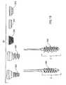
- FIG. 1Ais a lagwire system including a anchor component and wire in accordance with an exemplary embodiment of the present invention.
- FIG. 1Bis a lagwire system illustrating various thread combinations as embodiments of the present invention.
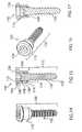
- FIG. 2Ais a quick cap in accordance with an exemplary embodiment of the present invention.
- FIG. 2Bis an alternative embodiment of a quick cap in accordance with an exemplary embodiment of the present invention.
- FIG. 2Cis a screw cap in accordance with an exemplary embodiment of the present invention.
- FIG. 2Dis a flat cap in accordance with an exemplary embodiment of the present invention.
- FIG. 2Fis a perspective view of another embodiment of a cap in accordance with an exemplary embodiment of the present invention.
- FIG. 2Gis a top view of an exemplary spring in accordance with an exemplary embodiment of the present invention.
- FIG. 2His an exploded perspective view a cap in accordance with an exemplary embodiment of the present invention.
- FIG. 2Iis a perspective view of the embodiment of the cap of FIG. 2H , fully assembled.
- FIG. 2Jis a cross section view of the embodiment of the cap shown in FIG. 2I .
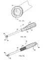
- FIG. 3Ais a tensioner in accordance with an exemplary embodiment of the present invention.
- FIG. 3Bis another embodiment of a tensioner in accordance with an exemplary embodiment of the present invention.
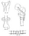
- FIG. 4Ais a fixation of a bone fracture in accordance with an exemplary embodiment of the present invention.
- FIGS. 4B-4Dare fixations of fractures of a certain portions of a bone in accordance with an exemplary embodiment of the present invention.
- FIG. 4Eis a fixation of a bone fracture by inserting the lagwire through the entire limb to facilitate attaching an external fixation device to the limb in accordance with an exemplary embodiment of the present invention.
- FIGS. 4F-4Gis a fixation of a bone fracture by inserting the lagwire through the entire limb to facilitate holding a plate to the bone to help fix certain types of fractures in accordance with an exemplary embodiment of the present invention.
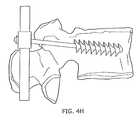
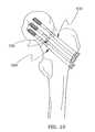
- FIG. 4His a fixation of a spinal injury in accordance with an exemplary embodiment of the present invention.
- FIG. 5Ais an exemplary head of the extractor of FIG. 5B in accordance with an exemplary embodiment of the present invention.
- FIG. 5Bis an exemplary extractor in accordance with an exemplary embodiment of the present invention.
- FIG. 5Cis another embodiment of an exemplary extractor in accordance with an exemplary embodiment of the present invention.
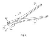
- FIG. 6is an exemplary cutter in accordance with an exemplary embodiment of the present invention.
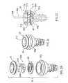
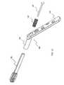
- FIG. 7is a cannulated screw having a sleeve and a threaded shaft in accordance with an exemplary embodiment of the present invention.
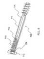
- FIG. 8is a cannulated screw having a sleeve, a compressive device and a threaded shaft and shown prior to extending the compressive device, in accordance with an exemplary embodiment of the present invention.
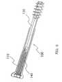
- FIG. 9is a cannulated screw having a sleeve, a compressive device and a threaded shaft and shown after extending the compressive device, in accordance with an exemplary embodiment of the present invention.
- FIG. 10shows multiple cannulated screws providing rotational stability to a fracture, in accordance with an exemplary embodiment of the present invention.
- FIG. 11shows a cannulated screw received through an intermedulary rod, in accordance with an exemplary embodiment of the present invention.
- FIG. 12shows a cannulated screw with a sleeve and a barrel as part of a hip screw plate system, in accordance with an exemplary embodiment of the present invention.
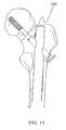
- FIG. 13shows another embodiment of a cannulated screw wherein the barrel functions as the sleeve, as part of a hip screw plate system, in accordance with an exemplary embodiment of the present invention.
- FIG. 14is a sleeve and a bone screw capable of receding within the sleeve in accordance with an exemplary embodiment of the present invention.
- FIG. 15is a cross section view of the sleeve and bone screw of FIG. 14 .
- FIG. 16is a perspective view of the sleeve and bone screw of FIGS. 14 and 15 shown with the bone screw recessed within the sleeve in accordance with an exemplary embodiment of the present invention.
- FIG. 17is a cross section view of the bone screw recessed within the sleeve of FIG. 16 .
- the present inventionfacilitates the change in distance between objects, object portions, or surfaces, compresses objects or object portions together, and/or provides a configurable or random amount of pressure between surfaces.
- the systemmay facilitate changing, maintaining, reducing and/or expanding the distance between objects or object portions.
- the applied pressuremay be suitably configured to be constant, increasing, decreasing, variable, random, and/or the like.
- the inventionincludes a device which may be fixedly or removably attached to pathology, such as to a certain portion of a bone.
- the deviceis fixedly or removably attached to the far cortex of the bone.
- the inventionincludes a device or method for retracting the attached device to reduce the distance between the surfaces of the pathology.
- the inventionincludes a device and/or method for maintaining the pressure between the surfaces of pathology.
- the lagwire system 1includes a head or anchor component 2 , a wire 12 and a cap 20 .
- the lagwire system 1may be fabricated using any type, amount or combination of materials suitably configured for the particular application.
- the lagwire system 1is fabricated with stainless steel, titanium and/or titanium alloy which minimize reactivity with the body.
- Each componentmay be fabricated with various diameters, thread pitches, lengths and/or the like.
- the anchor component 2may include threads, fins, tines, or any other fixation device or structure capable of securing the anchor component 2 to an object.
- Wire 12may form any cross-sectional shape, width, thickness, diameter, and surface features along its length, and thus, for example, may form a simple cylinder and/or may include ribs, threads, serrations, one or more flat surfaces, bumps, and/or roughened surfaces along its length.
- the anchor component 2is any device which is configured to fixedly or removably attach to any object, such as pathology.
- the anchor component 2is configured to be fixedly or removably attached to the far cortex of the bone, as shown in FIGS. 4A-4G . As best shown in FIG.
- the anchor component 2may include, for example, a self drilling tip 4 device which is suitably configured to puncture a hole and/or guide the anchor component 2 , self cutting threads 6 which are suitably configured to cut thread grooves into the inside surface of a hole, fastening threads 8 which are suitably configured to mate with the newly formed thread grooves, and a tool attachment 10 suitably configured for mating with a tool head (e.g., hex head wrench, socket wrench, Phillips screwdriver, flathead screwdriver, allen wrench and/or the like).
- a tool heade.g., hex head wrench, socket wrench, Phillips screwdriver, flathead screwdriver, allen wrench and/or the like.
- Anchor component 2may include different and interchangeable thread configurations, lengths, diameters, pitches and the like to facilitate insertion into different types of bone or other structures (e.g., cortical bone, cancellous bone, etc).
- cap 20may include different thread configurations, lengths, diameters, pitches and the like to facilitate insertion into different types of bone or other structures.
- both the anchor component 2 and/or cap 20may be interchangeably removed and replaced by different anchor components 2 and caps 20 with different thread configurations.
- the anchor component 2may not be removable from the remainder of the wire 12 .
- the anchor component 2includes leading threads 280 accommodating insertion into cortical bone while the cap 20 includes trailing threads 282 accommodating insertion into cortical bone.
- the anchor component 2includes leading threads 284 accommodating insertion into cancellous bone while the cap 20 includes trailing threads 286 accommodating insertion into cancellous bone.
- the anchor component 2includes leading threads 280 accommodating insertion into cortical bone while the cap 20 includes trailing threads 286 accommodating insertion into cancellous bone.
- the anchor component 2includes leading threads 284 accommodating insertion into cancellous bone while the cap 20 includes trailing threads 282 accommodating insertion into cortical bone.
- the anchor component 2includes leading threads 280 accommodating insertion into cortical bone while the cap 20 includes trailing threads 288 accommodating insertion a mechanical component such as a plate anchored into bone.
- the anchor component 2includes leading threads 284 accommodating insertion into cancellous bone while the cap 20 includes trailing threads 288 accommodating insertion a mechanical component such as a plate anchored into bone.
- the anchor component 2includes leading threads 280 accommodating insertion into cortical bone while the cap 20 includes a low-profile button-like design 290 that butts against the bone or a mechanical component.
- the anchor component 2includes leading threads 284 accommodating insertion into cancellous bone while the cap 20 includes a low-profile button-like design 290 that butts against the bone or a mechanical component.
- the anchor component 2includes leading threads 280 accommodating insertion into cortical bone while the cap 20 includes a low-profile button-like design that butts against the bone or a mechanical component and may also include spikes or teeth 292 to prevent rotation of the cap 20 .
- the anchor component 2includes leading threads 284 accommodating insertion into cancellous bone while the cap 20 includes a low-profile button-like design that butts against the bone or a mechanical component and may also include spikes or teeth 292 to prevent rotation of the cap 20 .
- a first cap 20includes cortical threads 282 , cancellous threads 286 , machine threads 288 accommodating insertion a mechanical component such as a plate anchored into bone, a low-profile button-like design 290 that butts against the bone or a mechanical component, and/or spikes or teeth 292 to prevent rotation of the first cap 20 ; and a second cap 20 includes cortical threads 282 , cancellous threads 286 , machine threads 288 accommodating insertion a mechanical component such as a plate anchored into bone, a low-profile button-like design 290 that butts against the bone or a mechanical component, and/or spikes or teeth 292 to prevent rotation of the second cap 20 .
- the tipis on the front end of anchor component 2 , followed by the cutting threads 6 , the fastening threads 8 , the tool attachment 10 , then wire 12 .
- the elements of anchor component 2may be fabricated as one component or one or more elements may be configured to be removably or fixedly mated together to form anchor component 2 . If mated together, a particular element may be exchanged for different applications. For example, if anchor component 2 needs to be inserted into a dense or hard bone, a stronger or sharper tip 4 may be screwed into thread element 6 , 8 . Moreover, if deeper thread grooves are desired, cutting threads 6 may be replaced with greater diameter threads. Furthermore, if a different tool head is incorporated into a drill, tool attachment 10 may be exchanged with the appropriate attachment.
- the outside diameter of the fastening threadsare similar to the thread diameters of known surgical screw sizes.
- Exemplary outside diameters of cortical anchor componentsinclude 3.5 mm and 4.5 mm, wherein the length of the thread section is similar to the cortex thickness.
- Exemplary outside diameters of cancellous (i.e., little or no cortex) anchor componentsinclude about 4.0 mm and 6.5 mm, wherein the length of the thread section may be about 16 mm or 32 mm.
- Wire 12is any device suitably configured, when force is applied, to reduce the distance between two surfaces.
- wire 12is configured to retract the anchor component 2 device to reduce the distance between the surfaces of the pathology.
- anchor component 2 and wire 12are constructed as one component.
- anchor component 2 and wire 12are constructed as separate components, but the components are configured such that the anchor component 2 may be threaded onto wire 12 after wire 12 is placed into the bone.
- Wire 12further includes an interface component 14 on at least a portion of its surface, wherein the interface component 14 is suitably configured to limit the movement of cap 20 to move distally toward anchor component 2 , but not proximally (backwards).
- interface component 14 of wire 12includes a sawtooth like configuration such that one side of each tooth (e.g. the side closest to anchor component 2 ) is substantially perpendicular to the surface of wire 12 , while the other side of the sawtooth is at a suitable angle, such as 45 degrees, thereby forming a triangular pattern for each sawtooth.
- a suitable anglesuch as 45 degrees
- any portion or the entire length of wire 12includes any configuration such as, for example, round, oval, flat on one or more portions of the wire, and/or microgrooves or ridges along the wire (which may include the sawtooth configuration, indentions or other configurations) to increase the friction along the wire.
- wire 12holds 20 pounds of pull; however, microgrooves in the wire may significantly increase the strength of the wire 12 .
- wire 12is comprised of a thin metal such as, for example, stainless steel, titanium and/or titanium alloy, so it may be easily cut to almost any desired length, thereby eliminating or reducing the need for fixed lengths screws.
- the inventionsubstantially reduces or eliminates the need for the inventory or availability of large screw sets or multiple screws.
- the systemmay include numerous materials, configurations and designs for either wire 12 or cap 20 , the invention provides increased versatility because the physician is provided with multiple options and choices for wire 12 and cap 20 combinations.
- Cap 20is any device suitably configured to maintain or increase the pressure between the surfaces of pathology by limiting wire 12 movement. As shown in FIGS. 2A-2E , exemplary caps 20 may include various configurations, materials, shapes and/or sizes. In one embodiment, and as shown in FIG. 2A , cap 20 includes an inverse interface component 22 relative to wire 12 interface component such that cap 20 is restricted from backwards translation after cap 20 is inserted over wire 12 . In one embodiment, the interface component 22 on cap 20 is located at least on the inside surface of the cap and includes a saw tooth pattern with the same or similar pitch as the saw tooth on wire 12 .
- cap 20also allows cap 20 to slide along wire 12 without the need for spinning cap 20 which is important because time is of the essence in a medical procedure and spinning the cap down a sufficiently long length of wire would be very time-consuming.
- Examples of cap 20include a screw cap 20 , flat cap 20 and a quick cap 20 .
- screw cap 20is configured with teeth 22 , cutting threads 24 and/or mating threads 26 on the outside surface to facilitate rotating cap 20 into the cortex to, for example, fix surgical plates against certain pathology.
- flat cap 20may include teeth 22 , cutting threads 24 and/or mating threads 26 on the outside surface to facilitate rotating cap 20 into the cortex, but it also is configured with a flat top surface 28 to allow cap 20 to be inserted into the cortex such that the flat top surface 28 of cap 20 does not substantially protrude from the cortex surface.
- the quick cap 20 or any other capmay be configured with only the interface component on the inside surface, thereby allowing for quick and easy assembly.
- cap 20is configured as a planar disk 30 with a center hole 32 , wherein the center hole 32 includes an interface component 34 on its inner circumference surface.
- the pitch of the saw tooth interface componentis about 0.25 mm-0.5 mm.
- the planar disk 30may also include any configuration for facilitating expansion of the disk 36 while sliding down wire 12 .
- the configurationsmay include, for example, a cut 38 or a hole 36 in the planar disk 30 .
- the planar diskmay include multiple holes or cuts spaced over the planar surface.
- One or more of the additional holes 36may also be connected to a cut 38 in the planar surface that extends to the center hole 32 .
- One or more of the holes 36may also be connected to a cut 40 in the planar surface that extends to the outside edge of the planar surface.
- six additional holes 36are evenly spaced around the planar surface with each hole 36 connected to a cut 38 which extends to the center hole, while one hole 36 also includes a cut 40 that extends to the outside edge of the planar surface.
- the planar diskmay also set inside a shallow cup device, wherein the circumference of the cup is slightly larger than the circumference of the planar ring in order to allow expansion of the ring.
- a springor any other device suitably configured to apply pressure to cap 20 , is placed between the planar ring and the cup device.
- a bellville springis used to apply pressure to the cap 20 .
- the springis configured to provide force on wire 12 after resorption. During the healing process, cartilage forms at the fracture and the cartilage compresses, so bone resorption typically occurs at the location of the fracture.
- cap 20allows for auto tightening of the lagwire because micro-motions or vibrations will often cause cap interface device 22 to click down another notch on the inverse interface device of the wire 12 .
- cap 20fits over one end of wire 12 , such that cap 20 permits travel of cap 20 in one direction (e.g., distal travel with respect to the wire, toward the bone), but resists travel of cap 20 in the other direction (e.g., proximal travel with respect to the wire, away from the bone).
- cap 20includes cutting threads 26 , cover 70 , a spring 80 and substantially flat surfaces 76 around the circumference of cap 20 to facilitate griping and/or turning cap 20 .
- Cap 20may be configured with a wider upper section which includes flat surfaces 76 around its circumference, and a tapered lower section with a gradually reducing diameter. Cutting threads 26 extend from the lower section.
- Cap 20may include different thread configurations, lengths, diameters, pitches and the like to facilitate insertion into different types of bone or other structures (e.g., cortical bone, cancellous bone, etc).
- Cover 70may be integral with cap 20 , or may be a separate component which is permanently or temporarily set in, or affixed to, cap 20 .
- cover 70includes an opening 72 (e.g., in center of cover 70 ) which receives wire 12 and an inlet 74 which is configured to receive a component of extractor tool 90 .
- tension spring 80is set inside cap 20 .
- tension spring 20sits within cap 20 below cover 70 ; is circular; includes opening 84 (e.g., in center of circular ring) which receives wire 12 ; includes an outer ring 82 and an inner ring 83 ; includes a cut into, or non-connecting portion 86 of, outer ring 82 and/or inner ring 83 ; and/or includes a tab 88 which extends outward from outer ring 82 .
- Outer ring 82 and an inner ring 83may be one integrated ring, or two or more separate rings, which may not be connected, or may be connected in any manner.
- At least a portion of inner ring 83(or any portion of inner circumference of tension spring 80 ) provides greater friction against wire 12 one way (e.g., when the cap is pulled proximal, away from the bone).
- the frictionis asserted against wire 12 because cover 70 impacts tab 88 , so tab 88 forces tension spring 80 to flex, torque and/or tilt (e.g., 15 degrees) opening 84 , thereby causing at least a portion of inner ring 83 to assert friction against at least a portion of wire 12 .
- tab 88is forced away from cover 70 and does not tilt, so it does not engage any surface, and the wire is able to translate, with minimal or no friction, through the central opening in the tension spring.
- FIG. 2Hshows and exploded view of an example of the cap 20 with a cover or recessed nut 70 , an angle or lever clutch 300 , a tension spring 80 , and a body 302 .
- the tension spring 80resides within a chamber of the body 302 , between the body 302 and the cover 70 .
- the locking lever clutch 70also resides between the body 302 and the cover 70 , and is in movable contact with the spring 80 .
- the spring 80is a flat spring washer that applies a preloaded force to the lever clutch 300 , biasing the lever clutch 300 to skew to a plane that is not parallel with the plane of the spring 80 .
- the lever clutch 300In its skewed state, the lever clutch 300 includes defines a hole 304 along a central axis 306 that is not coaxial with a central axis 308 of the cap 20 , and frictional edges 310 defining a portion of the hole 304 are forced into frictional contact with one or more flat or rounded outer surfaces of a wire 12 running along the axis 308 of the cap.
- the tension spring 80may, for example, be formed of a relatively thin layer of nitinol or another resilient material.
- the lever clutch 300may, for example, be formed of a thicker layer of stainless steel or titanium.
- the relatively thin layer of the tension spring 80occupies minimal space within the chamber of the body 302 , minimizing the overall size of the cap 20 .
- the relatively thick layer of the lever clutch 300provides greater surface area and strength to maximize stable and strong frictional contact and lock between the frictional edges 310 and the outer surface of the wire 12 .
- the lever clutch 300 and spring 80are either attached to each other or formed as a single structure and may be formed of identical or varying materials and thicknesses.
- the frictional edges 310permit distal movement of the cap 20 with respect to the wire 12 as the wire 12 moves through the central axis 308 of the cap 20 and forces or biases the locking lever clutch 300 to move upwards towards the cover 70 , towards a plane that is closer to parallel with the plane of the spring 80 , and in an orientation that permits the body of the wire 12 to move through the hole 304 with less frictional contact against the frictional edges 310 .
- the frictional edges 310resist proximal movement of the cap 20 with respect to the wire 12 as the wire 12 moves through the central axis 308 of the cap 20 and forces or biases the locking lever clutch 300 to move downwards away from the cover 70 , towards a plane that is closer to perpendicular with the plane of the spring 80 , and in an orientation that resists movement of the body of the wire 12 through the hole 304 as the frictional edges 310 are forced against and in increasing frictional contact with the outer surface of the body of the wire 12 .
- the embodiment of a cap 20 described with reference to FIGS. 2H , 2 I, and 2 Jcan be unlocked during or after initial implantation to make adjustments to, replace, or remove any or all of the system 1 .
- a usermay manually, or by means of a special hook-like tool, raise a handle 312 of the clutch 300 , for example, by exerting force on a lower edge 314 of the handle 312 in a direction that releases the friction edges 310 from their locking position with respect to the outer surface of the wire 12 .
- Extractor/Driver 90includes any device suitably configured to insert and/or extract cap 20 .
- extractor 90includes one or more ball bearings 91 , shaft 95 , shaft end 93 , handle 92 which receives shaft end 93 , tip sleeve 94 , tip 96 , and/or spring 97 .
- Tip 96may be the end of a long rod which extends upward into handle 92 .
- Spring 97applies pressure against the upper end of the rod that emanates from tip 96 , thereby asserting a load against tip 96 .
- Tip 96is thus configured to be received into inlet 74 of cap 20 and the spring-load maintains tip 96 in inlet 74 .
- Tip sleeve 94is configured to receive cap 20 to also facilitate rotation and/or translation of cap 20 .
- Tip 96is mounted on a disc such that it allows tip sleeve 94 to more fully receive cap 20 . The disc also rotates such that extractor 90 may rotate around cap 20 , with minimal or no movement of tip 96 .
- Ball bearings 91are configured to facilitate rotation of tip sleeve 94 around outer surface of cap 20 .
- the rodmay have a first end which includes tip 96 , and a second end 98 which may exit handle 92 such that the user may apply pressure to the second end 98 of the rod, thereby similarly applying pressure and a load against tip 96 .
- Exit handle 92also rotates such that it enables rotation of tip 96 which allows the user to rotate tip 96 until tip 96 mates with the inlet in cap 20 .
- collet sleeve 99is attached to collet advancing handle 89 .
- Collet advancing handle 89includes a threaded inner surface which is configured to advance shaft 95 , and thus, advance collet sleeve 99 forward over cap 20 to facilitate grasping of cap 20 for removal of cap 20 .
- tensioner 50may also be used in conjunction with the present invention.
- tensioner 50is any device suitably configured to insert a cap 20 into an object and/or provide tension to a wire 12 .
- tensioner 50increases the pressure between the surfaces of pathology by providing force to a wire 12 while the anchor component 2 of wire 12 is fixed into a bone or far cortex.
- tensioner 50includes a handle 52 with a hand trigger 54 , wherein the handle 52 supports a rotatable barrel 56 which mates with a cylindrical rod 58 .
- Cylindrical rod 58may be cannulated to receive wire 12 and/or have a driver 60 (e.g., hex, phillips, screw, allen and/or the like) at its distal end for mating with the tool attachment 10 of anchor component 2 .
- the barrel 56may be rotated manually or automatically in order to rotate the driver 60 into the object (e.g., bone or cortex).
- tensioner 50includes a means for exerting a force on wire 12 , such as, for example, internal gears 64 , wherein the gears 64 include an interface component 66 (e.g., saw tooth) which mate with the inverse sawtooth 20 on wire 12 .
- the tensioner 50may also include a gauge type device or any other device which is suitably configured to measure and/or display the tension exerted on wire 12 .
- tensioner 100includes a base 101 , a DVR connect component 102 , a handle 103 , a lock 104 , and/or a spring link 106 .
- Tensioner 100is configured to accept multiple size wires and may include an indicator to show the amount of tension being applied.
- Tensioner 101is also configured such that extractor 90 may clip into tensioner 101 .
- cutter 200may be used.
- Cutter 200includes insert left 201 , insert right 202 , jaw left 203 , jaw right 204 , cutter left 205 , and cutter right 206 .
- Cutter 200includes a cutting surface that extends beyond the main body of cutter 200 such that the wire may be cut from various angles.
- a cannulated lagwire driveris suitably attached to a surgical drill, such that the drill allows for automatic rotation of the driver.
- the wire 12 of lagwire system 1is placed into the channel of the driver such that the end of the driver encompasses or is received into driver head 10 of anchor component 2 , thereby allowing wire 12 to be drilled into the bone.
- anchor component 2is configured with a hex head as the driver head 10 such that the driver suitably mates to the hex head.
- the anchor component 2 and wire 12are then drilled into the bone to a desired depth using the automatic surgical drill (or any other manual or automatic device for rotating anchor component 2 ).
- drill tip 4 of anchor component 2facilitates the drilling of a pilot hole, wherein the proximal cutting threads 6 tap the bone for threading the inner surface of the hole, then the proximal mating threads 8 rotationally mate with the newly created threaded surface, thereby temporarily attaching the anchor component 2 into the cortex of the bone.
- a lagwire tensioneris used to exert tension on the lagwire.
- a lagwire tensioner 50may be used to force or seat cap 20 into the bone surface or any other desired position. The hex head 60 of the tensioner 50 may be used to screw cap 20 into the bone surface.
- the lagwire tensioner 50exerts tension on the lagwire 12 up to a desired tension which may be read from a gauge communicating with the tensioner.
- the excess wire 12may be suitably removed by, for example, a wire cutter or any other suitable device.
- a crimp type devicemay be placed on wire 12 to also help maintain tension.
- the crimpmay include a clamp type device, bending the existing wire 12 , screwing a nut onto the end of wire 12 and/or the like.
- the crimpmay be placed on wire 12 after cap 20 is set in place, for example, in order to crimp other end pieces together.
- the tensioner 50may also be used to reverse screw cap 20 in order to remove a wire 12 out of the bone.
- the present inventionallows the lagwire to be pushed through the opposite side of the bone and through the skin such that the anchor component 2 of wire 12 can be suitably removed (e.g., cut off) and a cap 20 can be placed onto that end of the lagwire, thereby resulting in better purchase (e.g., quality of fixation) of the bone.
- FIGS. 4A-4Gthe lagwire system discussed herein can be used for the fixation of various types of bone fractures.
- FIG. 4Ashows the use of the present invention for an exemplary fixation of a bone fracture or break.
- FIGS. 4B-4Dshow the use of the present invention for an exemplary fixation of fractures of certain portions of bones.
- the lagwire system 1may also be used in a similar manner discussed herein in order to assist in holding a plate to the bone to help fix certain types of fractures.
- the lagwiremay be placed through an entire limb to, for example, attach an external fixation device to the limb as shown in exemplary FIG. 4E .
- FIG. 4Hshows a fixation of a vertebrae in accordance with an exemplary embodiment of the present invention.
- the screwis inserted into the vertebrae, then a cap is fitted onto the end of the wire.
- the capis specially constructed such that the cap attaches to a rod.
- the rodmay extend along various vertebrae such that the lagwires may extend from various vertebrae and all connect to the same rod.
- Another screw and lagwiremay be inserted into the other side of the vertebrae such that the wire extends from the other side of the vertebrae and its cap connects to a second rod on the other side of the vertebrae for additional stability.
- the system and method of the present inventionprovides a device which is self-drilling, self-tapping and can be inserted under power.
- the inventionalso facilitates reducing and fixing fractures in one step.
- the inventionsubstantially expedites the process for fixation of bone fractures which is, of course, critical during trauma situations in order to stabilize a patient or to minimize the amount of time the patient is on the operating table or under anesthesia.
- the present inventionprovides the ability for two sides of cortex bone screw fixation.
- the inventionenables sufficient fixation even in poor quality bone material.
- the present inventiondoes not require the use of cannulated screws. Because the lagwire includes a tip 4 which creates a pilot hole, taps the bone for threads and fixes the threads into the bone, the system and method minimizes the possibility of inaccurate placement into the distal cortex or missing the distal hole.
- the physiciantypically cuts a relatively large opening in the skin in order to locate the bone segments, pull the bone segments into alignment, then place the screw into the bones.
- the systemfacilitates the percutaneous technique by allowing the physician to cut a minor incision into the skin for the anchor component, insert the anchor component, then pull the bones together with wire 12 and set the cap, all without large incisions or additional incisions.
- a bone fixation deviceincludes a collapsing bone fixation device which is suitably configured to collapse in association with a fracture collapse to minimize or prevent the device from protruding beyond the bone.
- the bone fixation devicealso includes an internal (i.e., minimal or no contact with the bone) compressive device 140 to maintain compression across the fracture during fracture collapse (e.g., weight bearing by the patient).
- an exemplary embodimentincludes an improved screw 100 having a sleeve 110 and a shaft 130 .
- a compressive device 140e.g. spring
- each of the elements sleeve 110 , shaft 130 , and compressive device 140are cannulated.
- shaft 130includes a first end 132 having a gripping device 133 and a second end 134 .
- Gripping device 133may include any structure and configuration for enabling shaft to enter and attach to an object.
- gripping deviceincludes a threaded surface thereon. The threaded surface may include cutting threads, mating threads, barbs, ribbed surface or any other surface configured to retain shaft 130 into an object.
- gripping device 133is about 0.63 inches in length with a pitch of about 9 threads per inch.
- shaft 130is generally cylindrical, but includes one or more flat outer surfaces 135 .
- second end 134includes two rectangular flat, opposing surfaces which extend over the entire length of shaft 130 , but terminate prior to gripping device 133 .
- the flat surfaces of shaft 130are each about 1.25 inches in length.
- second end 134 of shaft 130is configured to restrict shaft 130 from translating beyond a particular location with respect to the sleeve 110 .
- end cap 136is located on or near second end 134 , and is formed in a cylindrical configuration such that end cap 136 freely translates within the cylindrical portion of sleeve 110 , but end cap 136 stops the translation of shaft 130 , when end cap 136 impacts the flat inner surface of sleeve 110 .
- End cap 136limits the expansion of compressive device 140 to a certain point, so continued compression can be applied against the fracture.
- End cap 136may be integral with shaft 130 , welded onto shaft 130 , or otherwise affixed to shaft 130 .
- a wider diameter head 112is located at the first end of sleeve 110 .
- An exemplary diameter of head 112is about 0.387 inches.
- Head 112includes a recessed portion for receiving the hex head of a tool.
- the recessed portionis about 0.10 inches in depth and about 0.198 inches wide.
- Head 112(or any other portion of sleeve 110 ) may also include a ledge 114 ( FIG. 8 ) for retaining compressive device 140 within sleeve 110 .
- Cap 20(discussed above in other embodiments) may be configured as sleeve 110 (or barrel) and any components of cap 20 may be incorporated into bone screw 100 .
- a second end of sleeve 110includes an opening 116 which receives shaft 130 such that shaft 130 is able to at least partially move within sleeve 110 , with minimal or no movement of sleeve 110 .
- the inner surface of sleeve 110is generally cylindrical, but the inside surface also includes two rectangular flat, opposing surfaces which extend along a portion of the length of sleeve 110 .
- the overall sleeve 110is about 1.85 inches long, about 0.22 inches outer diameter, and about 0.161 inner diameter with a reduced distance between the flat surfaces of about 0.14 inches with the flat surfaces of sleeve 110 being each about 0.545 inches in length.
- a compressive device 140exists between sleeve 110 and shaft 130 such that compressive device 140 exerts a force directly or indirectly against shaft 130 .
- Compressive device 140may include, for example, a spring or any other element which exerts a force and/or bears a load.
- compressive device 140is located inside sleeve 110 (as discussed above).
- compressive device 140is a spring having about 10 mm of extension. As such, compressive device 140 allows about 10 mm of compression before sleeve head 112 is no longer held against the cortex.
- Compressive device 140may be suitably affixed to sleeve 110 and shaft 130 in any manner known in the art.
- first end of compressive device 140includes a larger diameter coil which sits upon ledge 114 of head 112 , thereby restricting or minimizing translation of compressive device 140 within sleeve 110 .
- the larger diameter coilmay also be further retained by a C-clip or laser welding to sleeve 110 (e.g., at any location within the first end).
- Second end of compressive device 140may include a tang 142 .
- Tang 142may extend longitudinally from the perimeter of the end coil. Tang 142 may be crimped into a hole in shaft 130 , laser welded to the end of shaft 130 and/or any other means for attaching tang 142 to shaft 130 .
- shaft 130may abut compressive device 140
- compressive device 140may receive shaft 130 within its coils, or compressive device 140 may abut a component attached to shaft 130 .
- compressive device 140may be a separate component suitably joined (e.g., welded, glued, molded) to shaft 130 and/or end cap 136 .
- Locating compressive device 140 inside sleeve 110is significantly advantageous because the compressive device is fully or partially protected from bone growth over and between the coils which may limit or destroy the functionality of the spring. Similarly, a re-absorbable material is not needed to be inserted between the coils in order to delay the compressive action of the spring. In other words, upon insertion, compressive device 140 is able to provide immediate and subsequent compression. Moreover, because shaft 130 and sleeve 110 rotate along with compressive device 140 , bone screw device 100 may be inserted or removed with minimal or no torque or unraveling of compressive device 140 .
- Multiple bone screws 100 of the present inventionmay also be used for rotational stability.
- more than one bone screwe.g., three
- Bone screw 100 of the present inventionmay be used in place of any existing bone screw, or any existing component of a product that performs a similar function as a bone screw. With respect to FIG. 11 , bone screw 100 is used in association with an intermedulary rod for additional support and stability.
- bone screw 100is incorporated into a compression/dynamic hip screw system 150 which may be used on, for example, a proximal femur fracture.
- An exemplary hip screw system 150may include any combination of the various compression hip screw plates and nails manufactured by Smith & Nephew.
- bone screw 100is received into barrel 152 of hip screw system 150 in place of the standard bone screw which is typically received into barrel 152 .
- Barrel 152may or may not include an additional compressive device 140 .
- barrel 152may act as a second sleeve 110 , thereby adding to the available translation of shaft 130 .
- shaft 130translates within sleeve 110 , and sleeve 110 itself may translate within barrel 152 before hip screw system 150 protrudes from the bone.
- sleeve 110is affixed directly to plate 155 , so a barrel is not needed.
- Hip screw system 150(with standard plate 155 and cortical bone screws) is inserted as is known in the art, and the features of the present invention incorporated into hip screw system 150 provide additional benefits by minimizing or preventing the device from protruding beyond the bone, and by maintaining an additional amount of compression across the fracture during fracture collapse.
- a T-Handlemay be used to rotate bone screw 100 into the bone.
- bone screw 100may replace or supplement any of the screws (e.g., cortical bone screws, medial fragment screws and/or main bone screw) typically used in association with hip screw system 150 .
- FIG. 13shows another embodiment of hip screw system 150 , wherein shaft 130 is received directly into barrel 152 of existing hip screw system 150 , without the need for a separate sleeve 110 .
- a standard barrel 152may be used or a longer opening formed within barrel 152 to allow shaft 130 greater translation within barrel 152 .
- Barrel 152may also include any of the features and functions described above with respect to sleeve 110 .
- barrel 152may include one or more flat inner portions to complement flat portion 135 of shaft 130 , a ledge 114 to hold a wider diameter spring, etc.
- Any of the hip screw systemsmay or may not incorporate a compressive device 140 inside sleeve 110 or barrel 152 . Without compressive device 140 , barrel 152 and/or sleeve 110 is still configured to allow shaft 130 to collapse within barrel 152 and/or sleeve 110 , as discussed above.
- Compression screw 157is inserted through plate 155 , through barrel 152 and into shaft 130 .
- the head of compression screw 157engages (or abuts) a recessed portion of plate 155 and/or a recessed portion of barrel 152 .
- shaft 130is “pulled” back into barrel 152 , thereby causing further compression.
- compression screw 157is also received through compressive device 140 which itself resides in barrel 152 and/or sleeve 110 .
- hip screw system 150Upon receiving a weight bearing load, hip screw system 150 allows shaft 130 to translate with minimal or no protrusion of hip screw system 150 beyond the bone, and also, maintaining an additional amount of compression across the fracture during fracture collapse.
- another exemplary embodimentincludes an improved screw 100 having a sleeve 110 and a shaft 130 .
- a compressive device 140e.g. split washer
- each of the elements sleeve 110 , shaft 130 , and compressive device 140may be cannulated.
- shaft 130includes a first end 132 having a gripping device 133 and a second end 134 .
- Gripping device 133may include any structure and configuration for enabling shaft to enter and attach to an object.
- gripping deviceincludes a threaded surface thereon. The threaded surface may include cutting threads, mating threads, barbs, ribbed surface or any other surface configured to retain shaft 130 into an object.
- gripping device 133is about 0.63 inches in length with a pitch of about 14.3 threads per inch.
- second end 134 of shaft 130is configured to restrict shaft 130 from translating beyond a particular location with respect to the sleeve 110 .
- end cap 136is located on or near second end 134 , and is formed in a cylindrical configuration such that end cap 136 freely translates within the cylindrical portion of sleeve 110 , but end cap 136 stops the translation of shaft 130 when a bottom edge 144 of end cap 136 compresses compressive device 140 against a flat inner surface or ledge 114 of sleeve 110 .
- An exemplary diameter of end cap 136is about 0.22 inches.
- End cap 136includes a recessed portion for receiving the hex head of a tool.
- end cap 136may be any configuration suitably configured to receive any suitable working tool.
- the recessed portionis about 0.1 inches in depth and about 0.12 inches wide.
- End cap 136may include an axial length that is shorter than the axial length of the cylindrical portion of sleeve 110 , such that end cap 136 may move within a range of distance capable of compressing, extending, and moving out of and into communication with compressive device 140 without exiting the chamber of the cylindrical portion of sleeve 110 .
- End cap 136ensures the compression of compressive device 140 so continued compression can be applied against the fracture.
- End cap 136may be integral with shaft 130 , welded onto shaft 130 , or otherwise affixed to shaft 130 .
- a head 112 with a diameter wider than the end cap 136may be located at the first end of sleeve 110 .
- sleeve 110may not include head 112 . Rather, sleeve 110 may merely rest flush with an object, such as a bone, without having any ridge resting on the exterior surface of the object.
- An exemplary diameter of head 112is about 0.4 inches.
- head 112includes a bottom edge 148 that abuts against the exterior surface of an object, such as a bone, bone plate 155 ( FIG. 13 ), or barrel 152 .
- sleeve 110may be formed as a barrel 152 .
- Head 112(or any other portion of sleeve 110 ) may also include a ledge 114 , as previously identified, for retaining compressive device 140 within sleeve 110 .
- Cap 20(discussed above in other embodiments) may be configured as sleeve 110 (or barrel) and any components of cap 20 may be incorporated into bone screw 100 .
- a second end of sleeve 110includes an opening 116 which receives shaft 130 such that shaft 130 is able to at least partially move within sleeve 110 , with minimal or no movement of sleeve 110 .
- the chamber within the cylindrical portion of the overall sleeve 110is about 7 mm long, and the overall sleeve 110 is about 0.3 inches wide at the outer diameter, and about 0.21 inches wide at the inner diameter.
- the overall end cap 136 located within the chamber of the cylindrical portion of sleeve 110is about 2.5 mm long and about 0.21 inches wide at the outer diameter.
- a compressive device 140exists between sleeve 110 and shaft 130 such that compressive device 140 exerts a force directly or indirectly against shaft 130 .
- Compressive device 140may include, for example, a spring, split washer, or any other element which exerts a force and/or bears a load.
- compressive device 140is located inside sleeve 110 (as discussed above).
- compressive device 140is a split washer having about 1 mm of expansion and compression formed in a helical shape.
- compressive device 140allows about 1 mm of compression before end cap 136 fully compresses compressive device 140 , or, conversely, about 1 mm of extension before end cap 136 fully relaxes compressive device 140 .
- end capmerely rests against relaxed and fully extended compressive device 140
- Compressive device 140is shown either relaxed and in contact with end cap 136 or at least partially compressed in FIG. 17 such that sleeve 110 and shaft 130 are at least in contact with or indirectly exerting force against each other.
- compressive device 140permits end cap 136 to recede within the cavity or chamber formed within the cylindrical portion of sleeve 110 , as shown in FIG. 16 .
- An exemplary method for inserting bone screw 100comprises drilling a bore hole into the two objects (e.g., two pieces of the fractured bone) which are to be compressed together.
- one or more coaxial bore holesmay be drilled, having different diameters and depths in order to accommodate the insertion of a sleeve 110 having a wider diameter and shorter depth than a shaft 130 having a narrower diameter and longer depth.
- a guide rodmay be inserted into the bore hole, then bone screw 100 may be inserted over the guide rod. Either head 112 ( FIGS.
- bone screw 100is then rotated (e.g. using a drill, hex head driver, or other suitable device) into and through the proximal bone portion or fragment.
- Head 132 of shaft 130then enters the distal bone portion or fragment.
- sleeve 110impacts or sits flush against the surface of the proximal bone portion or fragment (or against a plate placed over the bone portion or fragment), either head 112 ( FIGS. 7 through 9 ) or end cap 136 ( FIGS. 14 through 17 ), depending upon the embodiment employed, of sleeve 110 continues to rotate, but sleeve 110 no longer translates into the bone.
- the rotation of sleeve 110 or end cap 136continues to advance shaft 130 further into the distal bone portion or fragment because threads of gripping device 133 move shaft 130 forward.
- Such continued translation and penetration of shaft 130 into the distal bone portion or fragmentalso extends compressive device 140 (as best shown in FIG. 9 ) or compresses compressive device 140 (as best shown in FIGS. 16 and 17 ), depending upon the embodiment employed.
- the continued advance of shaft 130causes compressive device 140 to stretch beyond its relaxed condition (as shown in FIG. 9 ) or compress from its relaxed helical condition towards a flat condition (as shown in FIG. 17 ). After the bone screw is appropriately inserted, the guide rods are removed.
- shaft 130may penetrate into the distal bone portion or fragment any desired partial or full distance, and thus, extend or compress, as applicable, compressive device 140 to any desired partial or full extension, compression, or force.
- any “rotational insertion” discussed hereinmay alternatively or additionally include other means for insertion such as, for example, a direct translation using a hammer to force the shaft and/or sleeve into the bone.
- compressive device 140exerts force against sleeve 110 and shaft 130 , thereby forcing the components either toward or away from one another, depending upon the embodiment employed. Such force helps to maintain the compressive load at the union of the fracture. As additional compression is exerted on the load in a fracture collapse (e.g., from weight bearing), the bone is compressed closer together, so force may be reduced.
- the present inventioneither collapses or expands, as applicable, in association with the fracture collapse to substantially minimize or prevent sleeve head 112 of bone screw 100 ( FIGS. 7 through 9 ) from protruding beyond the bone or to substantially minimize or prevent end cap 136 of bone screw 100 ( FIGS.
- sleeve head 112is substantially maintained against the lateral cortex, while compressive device 140 maintains compression across the fracture during fracture collapse. That is, as the bone portions or fragments undergo stress relaxation, bone screw 100 similarly relaxes, while continuing to hold the portions or fragments together. As such, bone screw 100 continues to accommodate the stress relaxation of the bone portions or fragments until the fracture therebetween has significantly or completely healed.
- compressive device 140is a spring having about 10 mm of extension. As such, the spring allows about 10 mm of compression before shaft 130 impacts sleeve 110 so that sleeve head 112 is forced away from the cortex. Sleeve head 112 may be maintained against the lateral cortex until a sufficient amount of force no longer exists within compressive device 140 , then bone screw 100 may simply act as a traditional bone screw.
- compressive device 140is a split washer having about 1 mm of compression.
- the split washerallows about 1 mm of extension before end cap 136 of shaft 130 moves away from compressive device 140 in a direction towards the exit of the chamber of the cylindrical portion of sleeve 110 .
- the embodiment discussed with reference to FIGS. 14 through 17provides an additional advantage of permitting the shaft 130 to move fully exit sleeve 110 without ever forcing sleeve 110 or sleeve head 112 away from the cortex.
- the embodiment discussed with reference to FIGS. 14 through 17provides a sleeve head 112 that may be maintained against the lateral cortex until a sufficient amount of force no longer exists within compressive device 140 , then bone screw 100 may simply act as a traditional bone screw.
- the present inventionis described herein in connection with the fixation of bone fractures; however, one skilled in the art will appreciate that the lagwire or bone screw system and method described herein may also be used for changing, maintaining, reducing or expanding the distance between objects, object portions, or surfaces, compressing objects or object portions together, or providing pressure to surfaces.
- the present inventionmay be used to repair wood products, tree limb damage, breaks in supports or columns, cracks in sculptures or buildings, fractures in sections of concrete or other building materials, cracks or breaks in car parts and/or the like.
Landscapes
- Health & Medical Sciences (AREA)
- Orthopedic Medicine & Surgery (AREA)
- Surgery (AREA)
- Life Sciences & Earth Sciences (AREA)
- Heart & Thoracic Surgery (AREA)
- Nuclear Medicine, Radiotherapy & Molecular Imaging (AREA)
- Engineering & Computer Science (AREA)
- Biomedical Technology (AREA)
- Medical Informatics (AREA)
- Molecular Biology (AREA)
- Animal Behavior & Ethology (AREA)
- General Health & Medical Sciences (AREA)
- Public Health (AREA)
- Veterinary Medicine (AREA)
- Neurology (AREA)
- Surgical Instruments (AREA)
Abstract
Description
Claims (11)
Priority Applications (16)
| Application Number | Priority Date | Filing Date | Title |
|---|---|---|---|
| US11/952,715US8828067B2 (en) | 2001-10-18 | 2007-12-07 | Bone screw system and method |
| US12/104,328US20080243132A1 (en) | 2001-10-18 | 2008-04-16 | Tensioning system and method for the fixation of bone fractures |
| US12/104,658US20080243191A1 (en) | 2001-10-18 | 2008-04-17 | Adjustable bone plate fixation system and metho |
| US12/163,122US20090048606A1 (en) | 2001-10-18 | 2008-06-27 | Guide system and method for the fixation of bone fractures |
| US12/235,405US20090131936A1 (en) | 2001-10-18 | 2008-09-22 | System and method for the fixation of bone fractures |
| US12/258,013US20090131990A1 (en) | 2001-10-18 | 2008-10-24 | Bone screw system and method |
| US12/265,890US20090131991A1 (en) | 2001-10-18 | 2008-11-06 | System and method for the fixation of bone fractures |
| US12/491,132US20090306718A1 (en) | 2001-10-18 | 2009-06-24 | Filament and cap systems and methods for the fixation of bone fractures |
| US12/769,529US20100268285A1 (en) | 2001-10-18 | 2010-04-28 | Bone screw system and method for the fixation of bone fractures |
| US12/860,122US20100312292A1 (en) | 2001-10-18 | 2010-08-20 | Lagwire system and method for the fixation of bone fractures |
| US12/860,178US20100312245A1 (en) | 2001-10-18 | 2010-08-20 | Bone screw system and method for the fixation of bone fractures |
| US12/898,975US20110034925A1 (en) | 2001-10-18 | 2010-10-06 | Lagwire system and method for the fixation of bone fractures |
| US13/118,871US9060809B2 (en) | 2001-10-18 | 2011-05-31 | Lagwire system and method for the fixation of bone fractures |
| US14/449,555US9028534B2 (en) | 2001-10-18 | 2014-08-01 | Bone screw system and method |
| US14/683,478US20150223843A1 (en) | 2001-10-18 | 2015-04-10 | Bone screw system and method |
| US14/714,700US20150250503A1 (en) | 2001-10-18 | 2015-05-18 | Lagwire system and method for the fixation of bone fractures |
Applications Claiming Priority (6)
| Application Number | Priority Date | Filing Date | Title |
|---|---|---|---|
| US33018701P | 2001-10-18 | 2001-10-18 | |
| US10/272,773US6736819B2 (en) | 2001-10-18 | 2002-10-17 | System and method for fixation of bone fractures |
| US10/779,892US7591823B2 (en) | 2001-10-18 | 2004-02-17 | System and method for the fixation of bone fractures |
| US11/678,473US8679167B2 (en) | 2001-10-18 | 2007-02-23 | System and method for a cap used in the fixation of bone fractures |
| US11/742,457US8702768B2 (en) | 2001-10-18 | 2007-04-30 | Cannulated bone screw system and method |
| US11/952,715US8828067B2 (en) | 2001-10-18 | 2007-12-07 | Bone screw system and method |
Related Parent Applications (1)
| Application Number | Title | Priority Date | Filing Date |
|---|---|---|---|
| US11/742,457Continuation-In-PartUS8702768B2 (en) | 2001-10-18 | 2007-04-30 | Cannulated bone screw system and method |
Related Child Applications (4)
| Application Number | Title | Priority Date | Filing Date |
|---|---|---|---|
| US12/104,328Continuation-In-PartUS20080243132A1 (en) | 2001-10-18 | 2008-04-16 | Tensioning system and method for the fixation of bone fractures |
| US12/104,658Continuation-In-PartUS20080243191A1 (en) | 2001-10-18 | 2008-04-17 | Adjustable bone plate fixation system and metho |
| US12/235,405Continuation-In-PartUS20090131936A1 (en) | 2001-10-18 | 2008-09-22 | System and method for the fixation of bone fractures |
| US14/449,555ContinuationUS9028534B2 (en) | 2001-10-18 | 2014-08-01 | Bone screw system and method |
Publications (2)
| Publication Number | Publication Date |
|---|---|
| US20080147127A1 US20080147127A1 (en) | 2008-06-19 |
| US8828067B2true US8828067B2 (en) | 2014-09-09 |
Family
ID=39528451
Family Applications (3)
| Application Number | Title | Priority Date | Filing Date |
|---|---|---|---|
| US11/952,715Expired - LifetimeUS8828067B2 (en) | 2001-10-18 | 2007-12-07 | Bone screw system and method |
| US14/449,555Expired - Fee RelatedUS9028534B2 (en) | 2001-10-18 | 2014-08-01 | Bone screw system and method |
| US14/683,478AbandonedUS20150223843A1 (en) | 2001-10-18 | 2015-04-10 | Bone screw system and method |
Family Applications After (2)
| Application Number | Title | Priority Date | Filing Date |
|---|---|---|---|
| US14/449,555Expired - Fee RelatedUS9028534B2 (en) | 2001-10-18 | 2014-08-01 | Bone screw system and method |
| US14/683,478AbandonedUS20150223843A1 (en) | 2001-10-18 | 2015-04-10 | Bone screw system and method |
Country Status (1)
| Country | Link |
|---|---|
| US (3) | US8828067B2 (en) |
Cited By (53)
| Publication number | Priority date | Publication date | Assignee | Title |
|---|---|---|---|---|
| US20130184708A1 (en)* | 2010-08-29 | 2013-07-18 | Bonfix Ltd. | Orthopedic implant for treatment of bone deformities |
| US20140114365A1 (en)* | 2005-05-10 | 2014-04-24 | Acumed Llc | Bone connector with pivotable joint |
| US20140360123A1 (en)* | 2013-06-10 | 2014-12-11 | Mark A. Dicaire | Fastening System for Connecting Non-Load Bearing Wall to Truss |
| US20150073489A1 (en)* | 2013-09-06 | 2015-03-12 | Biomet Manufacturing, Llc | Implant fixation assembly |
| US20150223843A1 (en)* | 2001-10-18 | 2015-08-13 | Orthoip, Llc | Bone screw system and method |
| WO2016122944A1 (en)* | 2015-01-26 | 2016-08-04 | Panthera Medtech | Active tension bone and joint stabilization devices |
| WO2017058965A1 (en)* | 2015-09-28 | 2017-04-06 | Regenimmune, Inc. | Improved modular bone screw for surgical fixation to bone |
| US20180092681A1 (en)* | 2016-10-05 | 2018-04-05 | Bluewater Medical GmbH | Screw |
| US20180125477A1 (en)* | 2006-09-29 | 2018-05-10 | Biomet Sports Medicine, Llc | Fracture fixation device |
| US10136929B2 (en) | 2015-07-13 | 2018-11-27 | IntraFuse, LLC | Flexible bone implant |
| US10154863B2 (en) | 2015-07-13 | 2018-12-18 | IntraFuse, LLC | Flexible bone screw |
| US10159512B2 (en) | 2009-03-17 | 2018-12-25 | Bonfix Ltd | Hallux abducto valgus assemblies |
| US10485595B2 (en) | 2015-07-13 | 2019-11-26 | IntraFuse, LLC | Flexible bone screw |
| US10499960B2 (en) | 2015-07-13 | 2019-12-10 | IntraFuse, LLC | Method of bone fixation |
| US10575883B2 (en) | 2014-12-15 | 2020-03-03 | Smith & Nephew, Inc. | Active fracture compression implants |
| US10588679B2 (en) | 2014-11-01 | 2020-03-17 | Numagenesis, Llc | Compression fixation system |
| US10687803B2 (en) | 2006-02-03 | 2020-06-23 | Biomet Sports Medicine, Llc | Method and apparatus for coupling soft tissue to a bone |
| US10695045B2 (en) | 2006-09-29 | 2020-06-30 | Biomet Sports Medicine, Llc | Method and apparatus for attaching soft tissue to bone |
| US10716557B2 (en) | 2006-02-03 | 2020-07-21 | Biomet Sports Medicine, Llc | Method and apparatus for coupling anatomical features |
| US10729421B2 (en) | 2006-02-03 | 2020-08-04 | Biomet Sports Medicine, Llc | Method and apparatus for soft tissue fixation |
| US10743925B2 (en) | 2006-09-29 | 2020-08-18 | Biomet Sports Medicine, Llc | Fracture fixation device |
| US10758221B2 (en) | 2013-03-14 | 2020-09-01 | Biomet Sports Medicine, Llc | Scaffold for spring ligament repair |
| US10932770B2 (en) | 2006-02-03 | 2021-03-02 | Biomet Sports Medicine, Llc | Soft tissue repair device and associated methods |
| US10973507B2 (en) | 2006-02-03 | 2021-04-13 | Biomet Sports Medicine, Llc | Method and apparatus for coupling soft tissue to a bone |
| US10987099B2 (en) | 2006-02-03 | 2021-04-27 | Biomet Sports Medicine, Llc | Method for tissue fixation |
| US11020154B2 (en) | 2019-04-26 | 2021-06-01 | Warsaw Orthopedic, Inc. | Surgical instrument and methods of use |
| US11033308B2 (en) | 2017-08-09 | 2021-06-15 | Panther Orthopedics, Inc. | Active bone and joint stabilization device features |
| US11039826B2 (en) | 2006-02-03 | 2021-06-22 | Biomet Sports Medicine, Llc | Method and apparatus for forming a self-locking adjustable loop |
| US11045225B2 (en) | 2019-04-23 | 2021-06-29 | Panther Orthopedics, Inc. | Strength and fatigue life improvements for active bone and joint stabilization devices |
| US11065103B2 (en) | 2006-02-03 | 2021-07-20 | Biomet Sports Medicine, Llc | Method and apparatus for fixation of an ACL graft |
| US11096684B2 (en) | 2006-09-29 | 2021-08-24 | Biomet Sports Medicine, Llc | Method and apparatus for forming a self-locking adjustable loop |
| US11109857B2 (en) | 2004-11-05 | 2021-09-07 | Biomet Sports Medicine, Llc | Soft tissue repair device and method |
| US11116495B2 (en) | 2006-02-03 | 2021-09-14 | Biomet Sports Medicine, Llc | Soft tissue repair assembly and associated method |
| US11185320B2 (en) | 2007-04-10 | 2021-11-30 | Biomet Sports Medicine, Llc | Adjustable knotless loops |
| US11241305B2 (en) | 2011-11-03 | 2022-02-08 | Biomet Sports Medicine, Llc | Method and apparatus for stitching tendons |
| US11259794B2 (en) | 2006-09-29 | 2022-03-01 | Biomet Sports Medicine, Llc | Method for implanting soft tissue |
| US11259792B2 (en) | 2006-02-03 | 2022-03-01 | Biomet Sports Medicine, Llc | Method and apparatus for coupling anatomical features |
| US11311287B2 (en) | 2006-02-03 | 2022-04-26 | Biomet Sports Medicine, Llc | Method for tissue fixation |
| US11317956B1 (en)* | 2021-08-26 | 2022-05-03 | University Of Utah Research Foundation | Active compression bone screw |
| US11317907B2 (en) | 2006-02-03 | 2022-05-03 | Biomet Sports Medicine, Llc | Method and apparatus for forming a self-locking adjustable loop |
| US11376115B2 (en) | 2006-09-29 | 2022-07-05 | Biomet Sports Medicine, Llc | Prosthetic ligament system for knee joint |
| US11471147B2 (en) | 2006-02-03 | 2022-10-18 | Biomet Sports Medicine, Llc | Method and apparatus for coupling soft tissue to a bone |
| US11478289B2 (en) | 2018-05-04 | 2022-10-25 | Numagenesis, Llc | Compression fixation system |
| US11534157B2 (en) | 2011-11-10 | 2022-12-27 | Biomet Sports Medicine, Llc | Method for coupling soft tissue to a bone |
| US11589859B2 (en) | 2006-02-03 | 2023-02-28 | Biomet Sports Medicine, Llc | Method and apparatus for coupling soft tissue to bone |
| US11612391B2 (en) | 2007-01-16 | 2023-03-28 | Biomet Sports Medicine, Llc | Soft tissue repair device and associated methods |
| US11808034B2 (en) | 2019-03-08 | 2023-11-07 | Omg, Inc. | Floating connection fastening system |
| US11998255B1 (en) | 2023-08-26 | 2024-06-04 | University Of Utah Research Foundation | Cannulated continuous compression screw |
| US12096928B2 (en) | 2009-05-29 | 2024-09-24 | Biomet Sports Medicine, Llc | Method and apparatus for coupling soft tissue to a bone |
| US12245759B2 (en) | 2008-08-22 | 2025-03-11 | Biomet Sports Medicine, Llc | Method and apparatus for coupling soft tissue to bone |
| US12329373B2 (en) | 2011-05-02 | 2025-06-17 | Biomet Sports Medicine, Llc | Method and apparatus for soft tissue fixation |
| US12419632B2 (en) | 2008-08-22 | 2025-09-23 | Biomet Sports Medicine, Llc | Method and apparatus for coupling anatomical features |
| US12426871B2 (en) | 2022-08-24 | 2025-09-30 | Globus Medical, Inc. | Systems, devices and methods for implanting suture buttons |
Families Citing this family (38)
| Publication number | Priority date | Publication date | Assignee | Title |
|---|---|---|---|---|
| US8679167B2 (en) | 2001-10-18 | 2014-03-25 | Orthoip, Llc | System and method for a cap used in the fixation of bone fractures |
| US20110034925A1 (en)* | 2001-10-18 | 2011-02-10 | Orthoip, Llc | Lagwire system and method for the fixation of bone fractures |
| US20090254129A1 (en)* | 2007-04-30 | 2009-10-08 | Kishore Tipirneni | Bone screw system and method for the fixation of bone fractures |
| US20100268285A1 (en)* | 2001-10-18 | 2010-10-21 | Orthoip, Llc | Bone screw system and method for the fixation of bone fractures |
| US20090306718A1 (en)* | 2001-10-18 | 2009-12-10 | Orthoip, Llc | Filament and cap systems and methods for the fixation of bone fractures |
| US20090131990A1 (en)* | 2001-10-18 | 2009-05-21 | Kishore Tipirneni | Bone screw system and method |
| US6736819B2 (en) | 2001-10-18 | 2004-05-18 | Kishore Tipirneni | System and method for fixation of bone fractures |
| US9060809B2 (en)* | 2001-10-18 | 2015-06-23 | Orthoip, Llc | Lagwire system and method for the fixation of bone fractures |
| US8702768B2 (en) | 2001-10-18 | 2014-04-22 | Orthoip, Llc | Cannulated bone screw system and method |
| WO2007117571A2 (en)* | 2006-04-06 | 2007-10-18 | Lotus Medical, Llc | Active compression to facilitate healing of bones |
| US9247973B2 (en) | 2007-09-28 | 2016-02-02 | DePuy Synthes Products, Inc. | Anti-microbial implant |
| US9072561B2 (en)* | 2008-03-25 | 2015-07-07 | The Center For Orthopedic Research And Education, Inc. | Spinal facet fixation device |
| US8876821B2 (en) | 2010-11-24 | 2014-11-04 | Kyle Kinmon | Intramedullary nail, system, and method with dynamic compression |
| WO2012074991A1 (en)* | 2010-11-30 | 2012-06-07 | Amit Sinha | Bone compression and fixation devices |
| HK1201138A1 (en) | 2011-10-10 | 2015-08-28 | William Casey Fox | Shape changing bone implant for enhanced healing |
| US10179012B2 (en) | 2013-01-28 | 2019-01-15 | Cartiva, Inc. | Systems and methods for orthopedic repair |
| US9737294B2 (en) | 2013-01-28 | 2017-08-22 | Cartiva, Inc. | Method and system for orthopedic repair |
| US9730737B2 (en)* | 2013-03-14 | 2017-08-15 | Atlas Spine, Inc. | Facet fixation with anchor wire |
| US10080596B2 (en)* | 2013-12-09 | 2018-09-25 | Acumed Llc | Hip fixation with load-controlled dynamization |
| US10064670B2 (en)* | 2014-05-12 | 2018-09-04 | DePuy Synthes Products, Inc. | Sacral fixation system |
| CA2949060A1 (en)* | 2014-05-12 | 2015-11-19 | DePuy Synthes Products, Inc. | Sacral fixation system |
| US10478238B2 (en) | 2014-12-02 | 2019-11-19 | Activortho, Inc. | Active compression devices, methods of assembly and methods of use |
| US10105169B2 (en) | 2015-11-13 | 2018-10-23 | Leith Medical LLC | Bone fixation systems, apparatuses, and methods with anti-back-out feature |
| US10349996B2 (en) | 2015-12-07 | 2019-07-16 | Cable Fix LLC | Apparatus, system, and method for securing a tensioned cable through or around bone |
| CA3015902A1 (en) | 2016-02-26 | 2017-08-31 | Activortho, Inc. | Active compression apparatus, methods of assembly and methods of use |
| US11224467B2 (en) | 2016-02-26 | 2022-01-18 | Activortho, Inc. | Active compression apparatus, methods of assembly and methods of use |
| US10179016B1 (en)* | 2017-09-19 | 2019-01-15 | Cable Fix LLC | Apparatus, system, and method for crimping a cable for bone fixation |
| US10925654B2 (en) | 2017-09-19 | 2021-02-23 | Cable Fix LLC | Apparatus, system, and method for crimping a cable for bone fixation |
| RU2687754C1 (en)* | 2017-12-18 | 2019-05-16 | Федеральное Государственное бюджетное образовательное учреждение высшего образования Дагестанский государственный медицинский университет Министерства здравоохранения Российской Федерации | Device for femoral neck osteosynthesis |
| RU188428U1 (en)* | 2018-09-25 | 2019-04-11 | Общество С Ограниченной Ответственностью "Сахил" | SCREW FOR OSTEOSYNTHESIS OF THE FEMORAL NECK |
| MX2022004471A (en) | 2019-10-14 | 2022-08-16 | Leith Medical LLC | A BONE FIXATION SYSTEM WITH FASTENERS AND A REMOVAL TOOL TO DECOUPLATE FROM THE FASTENERS. |
| CA3157932A1 (en)* | 2019-10-14 | 2021-04-22 | Leith Medical, LLC | Apparatus for stablization of a bone fracture site |
| JP2023554581A (en) | 2020-11-11 | 2023-12-28 | アキュームド・エルエルシー | Tapered compression screw with non-constant pitch for dynamic compression |
| USD1019954S1 (en) | 2021-02-24 | 2024-03-26 | Medshape, Inc. | Dynamic compression device |
| US11291488B1 (en)* | 2021-02-24 | 2022-04-05 | Medshape, Inc. | Dynamic compression devices and processes for making and using same |
| US12023068B2 (en) | 2021-03-02 | 2024-07-02 | Medshape, Inc. | Resorption-controlled compression devices and processes for making and using the same |
| KR102572326B1 (en)* | 2021-07-01 | 2023-08-31 | 주식회사 제일메디칼코퍼레이션 | Leg screw for bone fixation having functions of length control and protrusion prevention |
| US12226135B1 (en)* | 2024-02-13 | 2025-02-18 | Surgeon Design Center LLC. | Surgical guide wire engagement device |
Citations (187)
| Publication number | Priority date | Publication date | Assignee | Title |
|---|---|---|---|---|
| US1025008A (en) | 1911-08-07 | 1912-04-30 | Lucien Luttrell Miner | Brace for fractured bones. |
| US1895845A (en)* | 1930-02-06 | 1933-01-31 | Internat Safety Lock Nut Corp | Screw stud locking device |
| US2077804A (en) | 1936-05-19 | 1937-04-20 | Morrison Gordon Monroe | Device for treating fractures of the neck of the femur |
| US2381050A (en) | 1943-12-04 | 1945-08-07 | Mervyn G Hardinge | Fracture reducing device |
| US2397545A (en) | 1945-02-13 | 1946-04-02 | Mervyn G Hardinge | Self-adjusting fracture reducing device |
| US2414882A (en) | 1943-09-24 | 1947-01-28 | Herschel Leiter H | Fracture reduction apparatus |
| US2490364A (en) | 1948-02-27 | 1949-12-06 | Herman H Livingston | Bone pin |
| US2511051A (en) | 1946-06-19 | 1950-06-13 | Dzus William | Fastening device |
| US2586556A (en)* | 1946-11-23 | 1952-02-19 | Mullikin Alfred | Flexible binder post |
| US3051169A (en)* | 1957-12-07 | 1962-08-28 | Stille Werner Ab | Surgical screw connector |
| US3433220A (en) | 1966-12-30 | 1969-03-18 | Robert E Zickel | Intramedullary rod and cross-nail assembly for treating femur fractures |
| US3489143A (en)* | 1967-12-15 | 1970-01-13 | William X Halloran | Convertible hip pin |
| US4341206A (en)* | 1978-12-19 | 1982-07-27 | Synthes Ag | Device for producing a hole in a bone |
| US4432358A (en)* | 1982-01-22 | 1984-02-21 | Fixel Irving E | Compression hip screw apparatus |
| US4456005A (en) | 1982-09-30 | 1984-06-26 | Lichty Terry K | External compression bone fixation device |
| GB2136688B (en) | 1983-03-18 | 1986-08-06 | Lilly Co Eli | Antibiotic or gemicide layered implants |
| US4617922A (en) | 1982-01-18 | 1986-10-21 | Richards Medical Company | Compression screw assembly |
| US4621629A (en)* | 1985-08-12 | 1986-11-11 | Harrington Arthritis Research Center | Compression hip screw |
| US4632100A (en) | 1985-08-29 | 1986-12-30 | Marlowe E. Goble | Suture anchor assembly |
| US4640271A (en)* | 1985-11-07 | 1987-02-03 | Zimmer, Inc. | Bone screw |
| US4688561A (en) | 1985-09-17 | 1987-08-25 | Reese H William | Bone handling apparatus and method |
| US4708132A (en) | 1986-01-24 | 1987-11-24 | Pfizer-Hospital Products Group, Inc. | Fixation device for a ligament or tendon prosthesis |
| US4741330A (en) | 1983-05-19 | 1988-05-03 | Hayhurst John O | Method and apparatus for anchoring and manipulating cartilage |
| US4773406A (en) | 1984-01-13 | 1988-09-27 | Ed. Geistlich Sohne Ag Fur Chemische Industrie | Bone fracture fixation plates |
| US4858601A (en) | 1988-05-27 | 1989-08-22 | Glisson Richard R | Adjustable compression bone screw |
| US4863383A (en) | 1987-03-17 | 1989-09-05 | Grafelmann Hans L | self-taping screw-in bone implant for dental purposes |
| US4889110A (en) | 1987-05-05 | 1989-12-26 | Yves Galline | Attaching device and tools for positioning same, especially for attaching the trochanter major to the femur |
| US4905680A (en) | 1986-10-27 | 1990-03-06 | Johnson & Johnson Orthopaedics, Inc. | Absorbable bone plate |
| US4934935A (en) | 1986-10-21 | 1990-06-19 | Edwards Barry N | Dental prostheses |
| US4940467A (en)* | 1988-02-03 | 1990-07-10 | Tronzo Raymond G | Variable length fixation device |
| US4959064A (en)* | 1988-10-07 | 1990-09-25 | Boehringer Mannheim Corporation | Dynamic tension bone screw |
| US5019079A (en) | 1989-11-20 | 1991-05-28 | Zimmer, Inc. | Bone screw |
| US5041116A (en) | 1990-05-21 | 1991-08-20 | Wilson James T | Compression hip screw system |
| US5061137A (en)* | 1991-04-29 | 1991-10-29 | Ford Motor Company | Fastener with resilient linking means |
| US5100405A (en)* | 1990-09-07 | 1992-03-31 | Mclaren Alexander C | Locking cap for medical implants |
| US5102276A (en)* | 1990-07-12 | 1992-04-07 | Ford Motor Company | Removable fastener with elastic linking means |
| US5116340A (en) | 1989-01-26 | 1992-05-26 | Songer Robert J | Surgical securance apparatus |
| US5116336A (en) | 1990-03-19 | 1992-05-26 | Synthes (U.S.A.) | Osteosynthetic anchor bolt |
| US5122133A (en)* | 1990-10-26 | 1992-06-16 | Smith & Nephew Richards Inc. | Compression screw for a joint endoprosthesis |
| US5127914A (en) | 1989-02-10 | 1992-07-07 | Calderale Pasquale M | Osteosynthesis means for the connection of bone fracture segments |
| US5129901A (en)* | 1991-06-10 | 1992-07-14 | Decoste Vern X | Cannulated orthopedic screw |
| US5141520A (en) | 1991-10-29 | 1992-08-25 | Marlowe Goble E | Harpoon suture anchor |
| US5207753A (en) | 1991-02-18 | 1993-05-04 | Kannivelu Badrinath | Bone fracture repair apparatus and method |
| US5217462A (en) | 1991-03-05 | 1993-06-08 | Pfizer Hospital Products Group, Inc. | Screw and driver |
| US5269784A (en) | 1991-12-10 | 1993-12-14 | Synthes (U.S.A.) | Screw nut for plate osteosynthesis |
| US5300075A (en) | 1991-09-18 | 1994-04-05 | Gordon Donn M | Cover for orthopedic splinting rods and method of installation |
| US5306290A (en) | 1993-02-12 | 1994-04-26 | Mitek Surgical Products, Inc. | Suture button |
| US5324292A (en) | 1993-02-10 | 1994-06-28 | Zimmer, Inc. | Fracture fixation assembly with selectively removable protrusion |
| US5336028A (en) | 1993-04-13 | 1994-08-09 | Vsi Corporation | Captive screw assembly |
| US5338139A (en) | 1993-10-20 | 1994-08-16 | Penn Engineering & Manufacturing Corp. | Shrouded captive screw |
| US5364398A (en) | 1986-06-23 | 1994-11-15 | Pfizer Hospital Products Group, Inc. | Modular femoral fixation system |
| US5368605A (en) | 1993-03-09 | 1994-11-29 | Miller, Jr.; Herman A. | Laparoscopic surgical instrument |
| US5382124A (en) | 1994-02-07 | 1995-01-17 | Southco, Inc. | Fully retractable captive screw |
| US5409493A (en) | 1990-07-13 | 1995-04-25 | Greenberg; Alex M. | Single-handed surgical drill depth guide |
| US5417692A (en) | 1994-01-04 | 1995-05-23 | Goble; E. Marlowe | Bone fixation and fusion system |
| US5423820A (en) | 1993-07-20 | 1995-06-13 | Danek Medical, Inc. | Surgical cable and crimp |
| US5431660A (en) | 1993-11-30 | 1995-07-11 | Burke; Dennis W. | Spring loaded screw and driver/extractor therefor |
| US5462547A (en) | 1991-05-30 | 1995-10-31 | Synthes (U.S.A.) | Trochanter stabilization device |
| US5507801A (en) | 1990-06-06 | 1996-04-16 | Synthes (U.S.A.) | Compression drill guide |
| US5520691A (en) | 1990-11-06 | 1996-05-28 | Branch; Thomas P. | Method and apparatus for re-approximating tissue |
| US5529075A (en) | 1994-09-12 | 1996-06-25 | Clark; David | Fixation device and method for repair of pronounced hallux valgus |
| US5586985A (en) | 1994-10-26 | 1996-12-24 | Regents Of The University Of Minnesota | Method and apparatus for fixation of distal radius fractures |
| US5591207A (en) | 1995-03-30 | 1997-01-07 | Linvatec Corporation | Driving system for inserting threaded suture anchors |
| US5601553A (en) | 1994-10-03 | 1997-02-11 | Synthes (U.S.A.) | Locking plate and bone screw |
| US5607426A (en) | 1995-04-13 | 1997-03-04 | Fastenletix, L.L.C. | Threaded polyaxial locking screw plate assembly |
| US5611801A (en) | 1994-11-29 | 1997-03-18 | Pioneer Laboratories, Inc. | Method and apparatus for bone fracture fixation |
| US5632745A (en) | 1995-02-07 | 1997-05-27 | R&D Biologicals, Inc. | Surgical implantation of cartilage repair unit |
| US5643267A (en) | 1992-03-10 | 1997-07-01 | Asahi Kogaku Kogyo Kabushiki Kaisha | Bone connector adapted for joining cut bone ends |
| US5702397A (en) | 1996-02-20 | 1997-12-30 | Medicinelodge, Inc. | Ligament bone anchor and method for its use |
| US5709687A (en) | 1994-03-16 | 1998-01-20 | Pennig; Dietmar | Fixation pin for small-bone fragments |
| US5725582A (en) | 1992-08-19 | 1998-03-10 | Surgicraft Limited | Surgical implants |
| US5743912A (en) | 1995-08-23 | 1998-04-28 | Biomat | Upper femoral epiphysis osteosynthesis implant |
| US5810821A (en) | 1997-03-28 | 1998-09-22 | Biomet Inc. | Bone fixation screw system |
| US5809849A (en) | 1996-02-08 | 1998-09-22 | Coffey; Kevin M. | Machine for stripping insulation from wire |
| US5827285A (en)* | 1996-12-12 | 1998-10-27 | Bramlet; Dale G. | Multipiece interfragmentary fixation assembly |
| US5893850A (en) | 1996-11-12 | 1999-04-13 | Cachia; Victor V. | Bone fixation device |
| US5893859A (en) | 1997-01-14 | 1999-04-13 | Teramed, Inc. | Method for forming custom length grafts after endoluminal insertion |
| US5899906A (en) | 1996-01-18 | 1999-05-04 | Synthes (U.S.A.) | Threaded washer |
| US5902011A (en) | 1995-06-09 | 1999-05-11 | Herman Miller, Inc. | Office chair and adjustable lumbar support therefor |
| US5928236A (en) | 1994-07-04 | 1999-07-27 | Depuy France | Locking pin or screw device for an osteosynthesis plate or for the coaptation of bone fragments |
| US5954722A (en) | 1997-07-29 | 1999-09-21 | Depuy Acromed, Inc. | Polyaxial locking plate |
| US5964763A (en) | 1997-02-14 | 1999-10-12 | Incavo; Stephen J. | Incrementally adjustable tibial osteotomy fixation device and method |
| US5964760A (en) | 1996-10-18 | 1999-10-12 | Spinal Innovations | Spinal implant fixation assembly |
| US5976139A (en) | 1996-07-17 | 1999-11-02 | Bramlet; Dale G. | Surgical fastener assembly |
| US5984925A (en) | 1997-07-30 | 1999-11-16 | Cross Medical Products, Inc. | Longitudinally adjustable bone plates and method for use thereof |
| US5993477A (en) | 1998-06-25 | 1999-11-30 | Ethicon Endo-Surgery, Inc. | Ultrasonic bone anchor |
| US5997538A (en) | 1998-03-23 | 1999-12-07 | New York Society For The Ruptured And Crippled Maintaining The Hospital For Special Surgery | Rotationally ratcheting bone screw |
| US6027523A (en) | 1997-10-06 | 2000-02-22 | Arthrex, Inc. | Suture anchor with attached disk |
| US6033429A (en) | 1998-01-13 | 2000-03-07 | Cardiac Assist Technologies, Inc. | System, apparatus and method for closing severed bone or tissue of a patient |
| US6039740A (en) | 1995-02-07 | 2000-03-21 | Olerud; Sven | Method and a device for implant locking |
| US6050998A (en) | 1999-05-21 | 2000-04-18 | Stephen A. Fletcher | Bone fastener |
| US6093188A (en) | 1997-11-10 | 2000-07-25 | Murray; William M. | Adjustable bone fixation plate |
| FR2784019B3 (en) | 1998-10-05 | 2000-08-04 | Jean Louis Audren | LOCKABLE ELASTIC CENTRO-MEDULAR NAIL FOR OSTEOSYNTHESIS OF HUMERUS FRACTURES |
| US6143037A (en) | 1996-06-12 | 2000-11-07 | The Regents Of The University Of Michigan | Compositions and methods for coating medical devices |
| US6171310B1 (en) | 1998-04-01 | 2001-01-09 | Aesculap Ag & Co. Kg | Device and method for handling an implant covering a bone tunnel |
| US6174312B1 (en) | 1996-09-05 | 2001-01-16 | Karl Laminger | Helical wire |
| US6174006B1 (en) | 1997-07-29 | 2001-01-16 | Illinois Tool Works Inc. | Tamper resistant seal |
| US6179537B1 (en)* | 1999-11-12 | 2001-01-30 | The Gleason Works | Clamping screw |
| US6235062B1 (en) | 1994-09-06 | 2001-05-22 | Finn Gramnas | Fastening device for prosthesis |
| GB2323533B (en) | 1997-03-25 | 2001-05-30 | Ioannis Karnezis | Orthopaedic modular compression screw system |
| US6245071B1 (en) | 1999-03-10 | 2001-06-12 | Synthes (U.S.A.) | External fixation device for bone |
| US6251111B1 (en) | 1999-10-20 | 2001-06-26 | Sdgi Holdings, Inc. | Jack for pulling a vertebral anchor |
| US6261291B1 (en) | 1999-07-08 | 2001-07-17 | David J. Talaber | Orthopedic implant assembly |
| US6319254B1 (en) | 1999-04-22 | 2001-11-20 | Newdeal | Compression osteosynthesis screw, and an ancillaty device for use therewith |
| US6368326B1 (en) | 1998-09-28 | 2002-04-09 | Daos Limited | Internal cord fixation device |
| US20020198527A1 (en) | 2001-06-21 | 2002-12-26 | Helmut Muckter | Implantable screw for stabilization of a joint or a bone fracture |
| US20030036761A1 (en) | 2001-07-09 | 2003-02-20 | Crista Smothers | Pharmacolgical sleeve |
| US6524313B1 (en) | 1999-10-14 | 2003-02-25 | Pega Medical | Intramedullary nail system |
| US20030083658A1 (en) | 2001-10-31 | 2003-05-01 | Ortho Development Corporation | Cervical plate for stabilizing the human spine |
| US6602293B1 (en) | 1996-11-01 | 2003-08-05 | The Johns Hopkins University | Polymeric composite orthopedic implant |
| US6605090B1 (en) | 2000-10-25 | 2003-08-12 | Sdgi Holdings, Inc. | Non-metallic implant devices and intra-operative methods for assembly and fixation |
| US6610067B2 (en) | 2000-05-01 | 2003-08-26 | Arthrosurface, Incorporated | System and method for joint resurface repair |
| US20030187440A1 (en) | 2002-03-12 | 2003-10-02 | Marc Richelsoph | Bone plate and screw retaining mechanism |
| US6629534B1 (en) | 1999-04-09 | 2003-10-07 | Evalve, Inc. | Methods and apparatus for cardiac valve repair |
| US6632224B2 (en)* | 1996-11-12 | 2003-10-14 | Triage Medical, Inc. | Bone fixation system |
| US20030216780A1 (en) | 2002-05-15 | 2003-11-20 | Fitts Steven E. | Two piece cross-pin graft fixation |
| US6656184B1 (en) | 2002-01-09 | 2003-12-02 | Biomet, Inc. | Bone screw with helical spring |
| US6656185B2 (en) | 2000-10-24 | 2003-12-02 | Spineology Inc. | Tension band clip |
| US6685706B2 (en) | 2001-11-19 | 2004-02-03 | Triage Medical, Inc. | Proximal anchors for bone fixation system |
| US6736819B2 (en) | 2001-10-18 | 2004-05-18 | Kishore Tipirneni | System and method for fixation of bone fractures |
| US20040097943A1 (en) | 1996-11-21 | 2004-05-20 | Hart Rickey D. | Apparatus for anchoring autologous or artificial tendon grafts in bone |
| US20040127906A1 (en)* | 2002-07-19 | 2004-07-01 | Culbert Brad S. | Method and apparatus for spinal fixation |
| US20040236424A1 (en) | 2001-05-25 | 2004-11-25 | Imaging Therapeutics, Inc. | Patient selectable joint arthroplasty devices and surgical tools facilitating increased accuracy, speed and simplicity in performing total and partial joint arthroplasty |
| US20040243129A1 (en) | 2003-05-28 | 2004-12-02 | Missoum Moumene | Double helical threaded bone screw |
| US6840953B2 (en) | 2000-12-22 | 2005-01-11 | United States Surgical Corporation | Suture screw |
| US20050010226A1 (en) | 2003-05-30 | 2005-01-13 | Grady Mark P. | Bone plate |
| US6887271B2 (en) | 2001-09-28 | 2005-05-03 | Ethicon, Inc. | Expanding ligament graft fixation system and method |
| US6887243B2 (en) | 2001-03-30 | 2005-05-03 | Triage Medical, Inc. | Method and apparatus for bone fixation with secondary compression |
| US6890333B2 (en) | 2001-03-30 | 2005-05-10 | Triage Medical, Inc. | Method and apparatus for bone fixation with secondary compression |
| US6902567B2 (en) | 2000-05-31 | 2005-06-07 | Silvana Vese | Device for fixing bone sections separated because of a fracture |
| US20050143735A1 (en)* | 2003-04-29 | 2005-06-30 | Kyle Richard F. | Double compression unloadable screw system |
| US20050234456A1 (en) | 2004-04-16 | 2005-10-20 | Malandain Hugues F | Plate system for minimally invasive support of the spine |
| US20050240190A1 (en)* | 2004-04-21 | 2005-10-27 | Gall Kenneth A | Osteosynthetic implants and methods of use and manufacture |
| US20050245933A1 (en) | 2004-05-03 | 2005-11-03 | Sevrain Lionel C | Multi coaxial screw system |
| US20050263549A1 (en) | 2002-06-03 | 2005-12-01 | Scheiner Rupert C | Medical device |
| US20050277940A1 (en)* | 2004-06-15 | 2005-12-15 | Neff James R | Dynamic compression device and driving tool |
| US6984241B2 (en) | 1996-09-13 | 2006-01-10 | Tendon Technology, Ltd. | Apparatus and methods for tendon or ligament repair |
| US7033363B2 (en) | 2004-05-19 | 2006-04-25 | Sean Powell | Snap-lock for drill sleeve |
| US20060129148A1 (en) | 2004-10-01 | 2006-06-15 | Simmons Edward D | Screw sleeve made of polyetheretherketone (PEEK) for augmentation of bone screw insertion in osteoporotic or revision lumbar spine instrumentation |
| US7070601B2 (en) | 2003-01-16 | 2006-07-04 | Triage Medical, Inc. | Locking plate for bone anchors |
| US20060147127A1 (en) | 2001-10-05 | 2006-07-06 | Micron Technology, Inc. | Method and apparatus for electronic image processing |
| US20060155297A1 (en)* | 2003-10-23 | 2006-07-13 | Ainsworth Stephen D | Driver assembly for simultaneous axial delivery of spinal implants |
| US20060161805A1 (en) | 2005-01-14 | 2006-07-20 | Charlie Tseng | Apparatus, system, and method for differential rebuilding of a reactivated offline RAID member disk |
| US20060167457A1 (en) | 2005-01-21 | 2006-07-27 | Loubert Suddaby | Orthopedic fusion plate having both active and passive subsidence controlling features |
| US7090676B2 (en) | 2002-11-19 | 2006-08-15 | Acumed Llc | Adjustable bone plates |
| US7094239B1 (en) | 1999-05-05 | 2006-08-22 | Sdgi Holdings, Inc. | Screws of cortical bone and method of manufacture thereof |
| US7094240B2 (en) | 2003-01-10 | 2006-08-22 | Sdgi Holdings, Inc. | Flexible member tensioning instruments and methods |
| US20060248638A1 (en) | 2005-05-06 | 2006-11-09 | Geberit Technik Ag | Discharge valve for a flushing cistern |
| US7135023B2 (en) | 2003-07-07 | 2006-11-14 | Watkins William T | Compression bone screw device |
| US20060264954A1 (en)* | 2005-04-07 | 2006-11-23 | Sweeney Thomas M Ii | Active compression screw system and method for using the same |
| US7147639B2 (en) | 2000-05-26 | 2006-12-12 | Orthofix S.R.L. | Disposable external fixation device |
| US7163542B2 (en) | 2004-03-30 | 2007-01-16 | Synthes (U.S.A.) | Adjustable depth drill bit |
| US7172595B1 (en) | 2000-10-03 | 2007-02-06 | Medicinelodge, Inc. | Bone fixation systems and related methods |
| US20070055249A1 (en) | 2003-06-20 | 2007-03-08 | Jensen David G | Bone plates with intraoperatively tapped apertures |
| US7189251B2 (en) | 1995-08-22 | 2007-03-13 | Orthohelix Surgical Designs, Inc. | Open helical organic tissue anchor having recessible head and method of making the organic tissue anchor |
| US20070123878A1 (en) | 2005-10-21 | 2007-05-31 | Shaver Joseph A | Orthopedic rod with locking aperture |
| US20070162019A1 (en) | 2005-12-21 | 2007-07-12 | Paul Burns | Resorbable anterior cervical plating system with screw retention mechanism |
| US20070162026A1 (en) | 2001-10-18 | 2007-07-12 | Fxdevices Llc | System and method for a cap used in the fixation of bone fractures |
| US20070190230A1 (en) | 2005-04-29 | 2007-08-16 | Trieu Hai H | Composite Spinal Fixation Systems |
| US20070233100A1 (en) | 2006-03-31 | 2007-10-04 | Metzinger Anthony J | Variable angle intramedullary nail |
| WO2007125561A1 (en) | 2006-04-28 | 2007-11-08 | Antonio Costa | Intra-bone screw for extra-dental fixing and wire with respective mutual coupling means, particularly for orthodontic use |
| US20070260248A1 (en) | 2001-10-18 | 2007-11-08 | Fxdevices, Llc | Cannulated bone screw system and method |
| US20070270855A1 (en) | 2006-04-06 | 2007-11-22 | Lotus Medical, Llc | Active compression to facilitate healing of bones |
| US20070270847A1 (en) | 2006-04-28 | 2007-11-22 | Shaw James A | Locking compression hip screw |
| US20070276382A1 (en) | 2006-05-09 | 2007-11-29 | Synthes (U.S.A.) | Nail System and Method for An Olecranon Osteotomy |
| US20080086144A1 (en) | 2003-06-20 | 2008-04-10 | Stryker Trauma Gmbh | Drilling tool guide wire alignment device |
| US20080147127A1 (en) | 2001-10-18 | 2008-06-19 | Fxdevices, Llc | Bone screw system and method |
| US20080147126A1 (en) | 2001-10-18 | 2008-06-19 | Fxdevices, Llc | System and method for a cap used in the fixation of bone fractures |
| US20080243191A1 (en) | 2001-10-18 | 2008-10-02 | Fx Devices, Llc | Adjustable bone plate fixation system and metho |
| US20080255555A1 (en) | 2007-04-11 | 2008-10-16 | Justis Jeff R | Temporary anchorable tether systems and methods |
| US20080255621A1 (en) | 2004-06-02 | 2008-10-16 | Synthes (U.S.A.) | Sleeve |
| US20080269746A1 (en) | 2007-04-24 | 2008-10-30 | Osteolign, Inc. | Conformable intramedullary implant with nestable components |
| US20080300636A1 (en) | 2007-02-14 | 2008-12-04 | Olivier Carli | Fracture reduction instrument for osseous body |
| US7476254B2 (en)* | 1993-11-01 | 2009-01-13 | Biomet Manufacturing Corporation | Compliant fixation for pelvis |
| US20090131936A1 (en) | 2001-10-18 | 2009-05-21 | Kishore Tipirneni | System and method for the fixation of bone fractures |
| US20090131990A1 (en) | 2001-10-18 | 2009-05-21 | Kishore Tipirneni | Bone screw system and method |
| US20090131991A1 (en) | 2001-10-18 | 2009-05-21 | Kishore Tipirneni | System and method for the fixation of bone fractures |
| US20090198288A1 (en) | 2008-01-31 | 2009-08-06 | Cayenne Medical, Inc. | Self-tapping biocompatible interference bone screw |
| US20090254129A1 (en) | 2007-04-30 | 2009-10-08 | Kishore Tipirneni | Bone screw system and method for the fixation of bone fractures |
| US20090306718A1 (en) | 2001-10-18 | 2009-12-10 | Orthoip, Llc | Filament and cap systems and methods for the fixation of bone fractures |
| US7641677B2 (en) | 2002-11-20 | 2010-01-05 | Orthopediatrics Corp. | Compression bone fragment wire |
| US20100114097A1 (en) | 2007-04-27 | 2010-05-06 | Synthes Usa, Llc | Implant Devices Constructed with Metallic and Polymeric Components |
| US7771428B2 (en) | 2004-06-11 | 2010-08-10 | Synthes Usa, Llc | Intramedullary rod with spiraling flutes |
| US20100312245A1 (en) | 2001-10-18 | 2010-12-09 | Orthoip, Llc | Bone screw system and method for the fixation of bone fractures |
| US20100312292A1 (en) | 2001-10-18 | 2010-12-09 | Orthoip, Llc | Lagwire system and method for the fixation of bone fractures |
| US20110034925A1 (en) | 2001-10-18 | 2011-02-10 | Orthoip, Llc | Lagwire system and method for the fixation of bone fractures |
| US20110295252A1 (en) | 2001-10-18 | 2011-12-01 | Orthoip, Llc | Lagwire system and method for the fixation of bone fractures |
Family Cites Families (31)
| Publication number | Priority date | Publication date | Assignee | Title |
|---|---|---|---|---|
| US200860A (en) | 1878-03-05 | Improvement in car-springs | ||
| US2086321A (en) | 1936-04-27 | 1937-07-06 | Kobe Seikosho Company Ltd | Spring |
| US2952254A (en) | 1958-11-06 | 1960-09-13 | George J Keating | Fastener |
| US3066274A (en) | 1960-06-03 | 1962-11-27 | Bell Telephone Labor Inc | Connection of insulated wire |
| US4147397A (en) | 1972-03-28 | 1979-04-03 | Sealectro Corporation | Electrical assembly in combination with printed circuit board |
| US3842824A (en)* | 1973-03-19 | 1974-10-22 | A Neufeld | Notched surgical pin and breaking tool therefor |
| US4035577A (en) | 1973-06-04 | 1977-07-12 | Thomas & Betts Corporation | Tubular ferrule |
| US4854797A (en) | 1988-10-05 | 1989-08-08 | Ford Motor Company | Threaded fastener with resilient linking means |
| US5171284A (en)* | 1989-04-25 | 1992-12-15 | Medevelop Ab | Method of inserting an anchoring element within a finger bone |
| US5098434A (en)* | 1990-11-28 | 1992-03-24 | Boehringer Mannheim Corporation | Porous coated bone screw |
| US5514138A (en)* | 1991-02-08 | 1996-05-07 | Pfizer Inc. | Connector having a stop member |
| US5498265A (en)* | 1991-03-05 | 1996-03-12 | Howmedica Inc. | Screw and driver |
| US5088123A (en) | 1991-05-10 | 1992-02-18 | Whiting And Davis Company, Inc. | Protective garment |
| US5190545A (en)* | 1991-08-27 | 1993-03-02 | Pfizer Hospital Products Group, Inc. | Cerclage wire positioning insert |
| US5360448A (en)* | 1991-10-07 | 1994-11-01 | Thramann Jeffrey J | Porous-coated bone screw for securing prosthesis |
| US5271543A (en) | 1992-02-07 | 1993-12-21 | Ethicon, Inc. | Surgical anastomosis stapling instrument with flexible support shaft and anvil adjusting mechanism |
| US5690666A (en) | 1992-11-18 | 1997-11-25 | Target Therapeutics, Inc. | Ultrasoft embolism coils and process for using them |
| FR2711505B1 (en)* | 1993-10-25 | 1995-12-29 | Tornier Sa | Device for synthesizing fractures of the upper end of the femur. |
| US5405073A (en) | 1993-12-06 | 1995-04-11 | Ethicon, Inc. | Flexible support shaft assembly |
| US6562052B2 (en) | 1995-08-24 | 2003-05-13 | Sutura, Inc. | Suturing device and method |
| US5741256A (en)* | 1997-01-13 | 1998-04-21 | Synthes (U.S.A.) | Helical osteosynthetic implant |
| US6078839A (en) | 1998-12-09 | 2000-06-20 | Pacesetter, Inc. | Abrasion resistant implantable lead insulation protector |
| US6334284B1 (en) | 1999-03-26 | 2002-01-01 | Anthony Italo Provitola | Structural system of torsion elements and method of construction therewith |
| DE29908360U1 (en) | 1999-05-11 | 2000-09-21 | Hehl, Gerhard, Dr.med., 89079 Ulm | Slide screw for the operative supply of e.g. Fractures of the femoral neck |
| US6645209B2 (en)* | 2000-04-04 | 2003-11-11 | Synthes (Usa) | Device for rotational stabilization of bone segments |
| DE602005023605D1 (en) | 2004-05-21 | 2010-10-28 | Myers Surgical Solutions Llc | FRACTURE FIXATION AND STITIZATION STABILIZATION SYSTEM |
| MX2010001827A (en) | 2007-08-14 | 2010-06-01 | Plastiflex Belgium | A respiratory system. |
| US20090228049A1 (en)* | 2008-03-09 | 2009-09-10 | Park Sangdo | Connecting Cannulated Bone Screws |
| JP2011523889A (en) | 2008-06-10 | 2011-08-25 | ソノマ・オーソペディック・プロダクツ・インコーポレーテッド | Device, tool and method for fixing fractures |
| ITBO20080370A1 (en) | 2008-06-11 | 2009-12-12 | Antonio Costa | INTRA-BONE SCREW FOR EXTRA-DENTAL ANCHORAGE AND METAL THREAD WITH MUTUAL COUPLING MEANS, PARTICULARLY FOR ORTHODONTIC USE |
| CN102123674A (en) | 2008-08-15 | 2011-07-13 | 活动脊柱技术有限公司 | Dynamic pedicle screw |
- 2007
- 2007-12-07USUS11/952,715patent/US8828067B2/ennot_activeExpired - Lifetime
- 2014
- 2014-08-01USUS14/449,555patent/US9028534B2/ennot_activeExpired - Fee Related
- 2015
- 2015-04-10USUS14/683,478patent/US20150223843A1/ennot_activeAbandoned
Patent Citations (197)
| Publication number | Priority date | Publication date | Assignee | Title |
|---|---|---|---|---|
| US1025008A (en) | 1911-08-07 | 1912-04-30 | Lucien Luttrell Miner | Brace for fractured bones. |
| US1895845A (en)* | 1930-02-06 | 1933-01-31 | Internat Safety Lock Nut Corp | Screw stud locking device |
| US2077804A (en) | 1936-05-19 | 1937-04-20 | Morrison Gordon Monroe | Device for treating fractures of the neck of the femur |
| US2414882A (en) | 1943-09-24 | 1947-01-28 | Herschel Leiter H | Fracture reduction apparatus |
| US2381050A (en) | 1943-12-04 | 1945-08-07 | Mervyn G Hardinge | Fracture reducing device |
| US2397545A (en) | 1945-02-13 | 1946-04-02 | Mervyn G Hardinge | Self-adjusting fracture reducing device |
| US2511051A (en) | 1946-06-19 | 1950-06-13 | Dzus William | Fastening device |
| US2586556A (en)* | 1946-11-23 | 1952-02-19 | Mullikin Alfred | Flexible binder post |
| US2490364A (en) | 1948-02-27 | 1949-12-06 | Herman H Livingston | Bone pin |
| US3051169A (en)* | 1957-12-07 | 1962-08-28 | Stille Werner Ab | Surgical screw connector |
| US3433220A (en) | 1966-12-30 | 1969-03-18 | Robert E Zickel | Intramedullary rod and cross-nail assembly for treating femur fractures |
| US3489143A (en)* | 1967-12-15 | 1970-01-13 | William X Halloran | Convertible hip pin |
| US4341206A (en)* | 1978-12-19 | 1982-07-27 | Synthes Ag | Device for producing a hole in a bone |
| US4617922A (en) | 1982-01-18 | 1986-10-21 | Richards Medical Company | Compression screw assembly |
| US4432358A (en)* | 1982-01-22 | 1984-02-21 | Fixel Irving E | Compression hip screw apparatus |
| US4456005A (en) | 1982-09-30 | 1984-06-26 | Lichty Terry K | External compression bone fixation device |
| GB2136688B (en) | 1983-03-18 | 1986-08-06 | Lilly Co Eli | Antibiotic or gemicide layered implants |
| US4741330A (en) | 1983-05-19 | 1988-05-03 | Hayhurst John O | Method and apparatus for anchoring and manipulating cartilage |
| US4773406A (en) | 1984-01-13 | 1988-09-27 | Ed. Geistlich Sohne Ag Fur Chemische Industrie | Bone fracture fixation plates |
| US4621629A (en)* | 1985-08-12 | 1986-11-11 | Harrington Arthritis Research Center | Compression hip screw |
| US4632100A (en) | 1985-08-29 | 1986-12-30 | Marlowe E. Goble | Suture anchor assembly |
| US4688561A (en) | 1985-09-17 | 1987-08-25 | Reese H William | Bone handling apparatus and method |
| US4640271A (en)* | 1985-11-07 | 1987-02-03 | Zimmer, Inc. | Bone screw |
| US4708132A (en) | 1986-01-24 | 1987-11-24 | Pfizer-Hospital Products Group, Inc. | Fixation device for a ligament or tendon prosthesis |
| US5364398A (en) | 1986-06-23 | 1994-11-15 | Pfizer Hospital Products Group, Inc. | Modular femoral fixation system |
| US4934935A (en) | 1986-10-21 | 1990-06-19 | Edwards Barry N | Dental prostheses |
| US4905680A (en) | 1986-10-27 | 1990-03-06 | Johnson & Johnson Orthopaedics, Inc. | Absorbable bone plate |
| US4863383A (en) | 1987-03-17 | 1989-09-05 | Grafelmann Hans L | self-taping screw-in bone implant for dental purposes |
| US4889110A (en) | 1987-05-05 | 1989-12-26 | Yves Galline | Attaching device and tools for positioning same, especially for attaching the trochanter major to the femur |
| US4940467A (en)* | 1988-02-03 | 1990-07-10 | Tronzo Raymond G | Variable length fixation device |
| US4858601A (en) | 1988-05-27 | 1989-08-22 | Glisson Richard R | Adjustable compression bone screw |
| US4959064A (en)* | 1988-10-07 | 1990-09-25 | Boehringer Mannheim Corporation | Dynamic tension bone screw |
| US5116340A (en) | 1989-01-26 | 1992-05-26 | Songer Robert J | Surgical securance apparatus |
| US5127914A (en) | 1989-02-10 | 1992-07-07 | Calderale Pasquale M | Osteosynthesis means for the connection of bone fracture segments |
| US5019079A (en) | 1989-11-20 | 1991-05-28 | Zimmer, Inc. | Bone screw |
| US5116336A (en) | 1990-03-19 | 1992-05-26 | Synthes (U.S.A.) | Osteosynthetic anchor bolt |
| US5041116A (en) | 1990-05-21 | 1991-08-20 | Wilson James T | Compression hip screw system |
| US5507801A (en) | 1990-06-06 | 1996-04-16 | Synthes (U.S.A.) | Compression drill guide |
| US5102276A (en)* | 1990-07-12 | 1992-04-07 | Ford Motor Company | Removable fastener with elastic linking means |
| US5409493A (en) | 1990-07-13 | 1995-04-25 | Greenberg; Alex M. | Single-handed surgical drill depth guide |
| US5100405A (en)* | 1990-09-07 | 1992-03-31 | Mclaren Alexander C | Locking cap for medical implants |
| US5122133A (en)* | 1990-10-26 | 1992-06-16 | Smith & Nephew Richards Inc. | Compression screw for a joint endoprosthesis |
| US5520691A (en) | 1990-11-06 | 1996-05-28 | Branch; Thomas P. | Method and apparatus for re-approximating tissue |
| US5207753A (en) | 1991-02-18 | 1993-05-04 | Kannivelu Badrinath | Bone fracture repair apparatus and method |
| US5217462A (en) | 1991-03-05 | 1993-06-08 | Pfizer Hospital Products Group, Inc. | Screw and driver |
| US5061137A (en)* | 1991-04-29 | 1991-10-29 | Ford Motor Company | Fastener with resilient linking means |
| US5462547A (en) | 1991-05-30 | 1995-10-31 | Synthes (U.S.A.) | Trochanter stabilization device |
| US5129901A (en)* | 1991-06-10 | 1992-07-14 | Decoste Vern X | Cannulated orthopedic screw |
| US5300075A (en) | 1991-09-18 | 1994-04-05 | Gordon Donn M | Cover for orthopedic splinting rods and method of installation |
| US5141520A (en) | 1991-10-29 | 1992-08-25 | Marlowe Goble E | Harpoon suture anchor |
| US5269784A (en) | 1991-12-10 | 1993-12-14 | Synthes (U.S.A.) | Screw nut for plate osteosynthesis |
| US5643267A (en) | 1992-03-10 | 1997-07-01 | Asahi Kogaku Kogyo Kabushiki Kaisha | Bone connector adapted for joining cut bone ends |
| US5725582A (en) | 1992-08-19 | 1998-03-10 | Surgicraft Limited | Surgical implants |
| US5324292A (en) | 1993-02-10 | 1994-06-28 | Zimmer, Inc. | Fracture fixation assembly with selectively removable protrusion |
| US5306290A (en) | 1993-02-12 | 1994-04-26 | Mitek Surgical Products, Inc. | Suture button |
| US5368605A (en) | 1993-03-09 | 1994-11-29 | Miller, Jr.; Herman A. | Laparoscopic surgical instrument |
| US5336028A (en) | 1993-04-13 | 1994-08-09 | Vsi Corporation | Captive screw assembly |
| US5423820A (en) | 1993-07-20 | 1995-06-13 | Danek Medical, Inc. | Surgical cable and crimp |
| US5338139A (en) | 1993-10-20 | 1994-08-16 | Penn Engineering & Manufacturing Corp. | Shrouded captive screw |
| US7476254B2 (en)* | 1993-11-01 | 2009-01-13 | Biomet Manufacturing Corporation | Compliant fixation for pelvis |
| US5431660A (en) | 1993-11-30 | 1995-07-11 | Burke; Dennis W. | Spring loaded screw and driver/extractor therefor |
| US5417692A (en) | 1994-01-04 | 1995-05-23 | Goble; E. Marlowe | Bone fixation and fusion system |
| US5382124A (en) | 1994-02-07 | 1995-01-17 | Southco, Inc. | Fully retractable captive screw |
| US5709687A (en) | 1994-03-16 | 1998-01-20 | Pennig; Dietmar | Fixation pin for small-bone fragments |
| US5928236A (en) | 1994-07-04 | 1999-07-27 | Depuy France | Locking pin or screw device for an osteosynthesis plate or for the coaptation of bone fragments |
| US6235062B1 (en) | 1994-09-06 | 2001-05-22 | Finn Gramnas | Fastening device for prosthesis |
| US5529075A (en) | 1994-09-12 | 1996-06-25 | Clark; David | Fixation device and method for repair of pronounced hallux valgus |
| US5601553A (en) | 1994-10-03 | 1997-02-11 | Synthes (U.S.A.) | Locking plate and bone screw |
| US5586985A (en) | 1994-10-26 | 1996-12-24 | Regents Of The University Of Minnesota | Method and apparatus for fixation of distal radius fractures |
| US5611801A (en) | 1994-11-29 | 1997-03-18 | Pioneer Laboratories, Inc. | Method and apparatus for bone fracture fixation |
| US6039740A (en) | 1995-02-07 | 2000-03-21 | Olerud; Sven | Method and a device for implant locking |
| US5632745A (en) | 1995-02-07 | 1997-05-27 | R&D Biologicals, Inc. | Surgical implantation of cartilage repair unit |
| US5591207A (en) | 1995-03-30 | 1997-01-07 | Linvatec Corporation | Driving system for inserting threaded suture anchors |
| US5607426A (en) | 1995-04-13 | 1997-03-04 | Fastenletix, L.L.C. | Threaded polyaxial locking screw plate assembly |
| US5902011A (en) | 1995-06-09 | 1999-05-11 | Herman Miller, Inc. | Office chair and adjustable lumbar support therefor |
| US7189251B2 (en) | 1995-08-22 | 2007-03-13 | Orthohelix Surgical Designs, Inc. | Open helical organic tissue anchor having recessible head and method of making the organic tissue anchor |
| US5743912A (en) | 1995-08-23 | 1998-04-28 | Biomat | Upper femoral epiphysis osteosynthesis implant |
| US5899906A (en) | 1996-01-18 | 1999-05-04 | Synthes (U.S.A.) | Threaded washer |
| US5997541A (en)* | 1996-01-18 | 1999-12-07 | Synthes (U.S.A) | Threaded washer |
| US5809849A (en) | 1996-02-08 | 1998-09-22 | Coffey; Kevin M. | Machine for stripping insulation from wire |
| US5702397A (en) | 1996-02-20 | 1997-12-30 | Medicinelodge, Inc. | Ligament bone anchor and method for its use |
| US6695844B2 (en) | 1996-03-13 | 2004-02-24 | Orthopedic Designs, Inc. | Surgical fastener assembly |
| US6183474B1 (en) | 1996-03-13 | 2001-02-06 | Dale G. Bramlet | Surgical fastener assembly |
| US6143037A (en) | 1996-06-12 | 2000-11-07 | The Regents Of The University Of Michigan | Compositions and methods for coating medical devices |
| US5976139A (en) | 1996-07-17 | 1999-11-02 | Bramlet; Dale G. | Surgical fastener assembly |
| US6174312B1 (en) | 1996-09-05 | 2001-01-16 | Karl Laminger | Helical wire |
| US6984241B2 (en) | 1996-09-13 | 2006-01-10 | Tendon Technology, Ltd. | Apparatus and methods for tendon or ligament repair |
| US5964760A (en) | 1996-10-18 | 1999-10-12 | Spinal Innovations | Spinal implant fixation assembly |
| US6602293B1 (en) | 1996-11-01 | 2003-08-05 | The Johns Hopkins University | Polymeric composite orthopedic implant |
| US6348053B1 (en) | 1996-11-12 | 2002-02-19 | Triage Medical, Inc. | Bone fixation device |
| US6632224B2 (en)* | 1996-11-12 | 2003-10-14 | Triage Medical, Inc. | Bone fixation system |
| US7008428B2 (en) | 1996-11-12 | 2006-03-07 | Triage Medical, Inc. | Bone fixation system |
| US5893850A (en) | 1996-11-12 | 1999-04-13 | Cachia; Victor V. | Bone fixation device |
| US20040097943A1 (en) | 1996-11-21 | 2004-05-20 | Hart Rickey D. | Apparatus for anchoring autologous or artificial tendon grafts in bone |
| US5827285A (en)* | 1996-12-12 | 1998-10-27 | Bramlet; Dale G. | Multipiece interfragmentary fixation assembly |
| US5893859A (en) | 1997-01-14 | 1999-04-13 | Teramed, Inc. | Method for forming custom length grafts after endoluminal insertion |
| US5964763A (en) | 1997-02-14 | 1999-10-12 | Incavo; Stephen J. | Incrementally adjustable tibial osteotomy fixation device and method |
| GB2323533B (en) | 1997-03-25 | 2001-05-30 | Ioannis Karnezis | Orthopaedic modular compression screw system |
| US5810821A (en) | 1997-03-28 | 1998-09-22 | Biomet Inc. | Bone fixation screw system |
| US6174006B1 (en) | 1997-07-29 | 2001-01-16 | Illinois Tool Works Inc. | Tamper resistant seal |
| US5954722A (en) | 1997-07-29 | 1999-09-21 | Depuy Acromed, Inc. | Polyaxial locking plate |
| US5984925A (en) | 1997-07-30 | 1999-11-16 | Cross Medical Products, Inc. | Longitudinally adjustable bone plates and method for use thereof |
| US6027523A (en) | 1997-10-06 | 2000-02-22 | Arthrex, Inc. | Suture anchor with attached disk |
| US6093188A (en) | 1997-11-10 | 2000-07-25 | Murray; William M. | Adjustable bone fixation plate |
| US6033429A (en) | 1998-01-13 | 2000-03-07 | Cardiac Assist Technologies, Inc. | System, apparatus and method for closing severed bone or tissue of a patient |
| US5997538A (en) | 1998-03-23 | 1999-12-07 | New York Society For The Ruptured And Crippled Maintaining The Hospital For Special Surgery | Rotationally ratcheting bone screw |
| US6171310B1 (en) | 1998-04-01 | 2001-01-09 | Aesculap Ag & Co. Kg | Device and method for handling an implant covering a bone tunnel |
| US5993477A (en) | 1998-06-25 | 1999-11-30 | Ethicon Endo-Surgery, Inc. | Ultrasonic bone anchor |
| US6368326B1 (en) | 1998-09-28 | 2002-04-09 | Daos Limited | Internal cord fixation device |
| FR2784019B3 (en) | 1998-10-05 | 2000-08-04 | Jean Louis Audren | LOCKABLE ELASTIC CENTRO-MEDULAR NAIL FOR OSTEOSYNTHESIS OF HUMERUS FRACTURES |
| US6245071B1 (en) | 1999-03-10 | 2001-06-12 | Synthes (U.S.A.) | External fixation device for bone |
| US6629534B1 (en) | 1999-04-09 | 2003-10-07 | Evalve, Inc. | Methods and apparatus for cardiac valve repair |
| US6319254B1 (en) | 1999-04-22 | 2001-11-20 | Newdeal | Compression osteosynthesis screw, and an ancillaty device for use therewith |
| US7094239B1 (en) | 1999-05-05 | 2006-08-22 | Sdgi Holdings, Inc. | Screws of cortical bone and method of manufacture thereof |
| US6050998A (en) | 1999-05-21 | 2000-04-18 | Stephen A. Fletcher | Bone fastener |
| US6261291B1 (en) | 1999-07-08 | 2001-07-17 | David J. Talaber | Orthopedic implant assembly |
| US6524313B1 (en) | 1999-10-14 | 2003-02-25 | Pega Medical | Intramedullary nail system |
| US6251111B1 (en) | 1999-10-20 | 2001-06-26 | Sdgi Holdings, Inc. | Jack for pulling a vertebral anchor |
| US6179537B1 (en)* | 1999-11-12 | 2001-01-30 | The Gleason Works | Clamping screw |
| US6610067B2 (en) | 2000-05-01 | 2003-08-26 | Arthrosurface, Incorporated | System and method for joint resurface repair |
| US7147639B2 (en) | 2000-05-26 | 2006-12-12 | Orthofix S.R.L. | Disposable external fixation device |
| US6902567B2 (en) | 2000-05-31 | 2005-06-07 | Silvana Vese | Device for fixing bone sections separated because of a fracture |
| US7172595B1 (en) | 2000-10-03 | 2007-02-06 | Medicinelodge, Inc. | Bone fixation systems and related methods |
| US6656185B2 (en) | 2000-10-24 | 2003-12-02 | Spineology Inc. | Tension band clip |
| US6605090B1 (en) | 2000-10-25 | 2003-08-12 | Sdgi Holdings, Inc. | Non-metallic implant devices and intra-operative methods for assembly and fixation |
| US6840953B2 (en) | 2000-12-22 | 2005-01-11 | United States Surgical Corporation | Suture screw |
| US6887243B2 (en) | 2001-03-30 | 2005-05-03 | Triage Medical, Inc. | Method and apparatus for bone fixation with secondary compression |
| US6908465B2 (en) | 2001-03-30 | 2005-06-21 | Triage Medical, Inc. | Distal bone anchors for bone fixation with secondary compression |
| US6890333B2 (en) | 2001-03-30 | 2005-05-10 | Triage Medical, Inc. | Method and apparatus for bone fixation with secondary compression |
| US20040236424A1 (en) | 2001-05-25 | 2004-11-25 | Imaging Therapeutics, Inc. | Patient selectable joint arthroplasty devices and surgical tools facilitating increased accuracy, speed and simplicity in performing total and partial joint arthroplasty |
| US20020198527A1 (en) | 2001-06-21 | 2002-12-26 | Helmut Muckter | Implantable screw for stabilization of a joint or a bone fracture |
| US20030036761A1 (en) | 2001-07-09 | 2003-02-20 | Crista Smothers | Pharmacolgical sleeve |
| US6887271B2 (en) | 2001-09-28 | 2005-05-03 | Ethicon, Inc. | Expanding ligament graft fixation system and method |
| US20060147127A1 (en) | 2001-10-05 | 2006-07-06 | Micron Technology, Inc. | Method and apparatus for electronic image processing |
| US20090131990A1 (en) | 2001-10-18 | 2009-05-21 | Kishore Tipirneni | Bone screw system and method |
| US20070260248A1 (en) | 2001-10-18 | 2007-11-08 | Fxdevices, Llc | Cannulated bone screw system and method |
| US20110295252A1 (en) | 2001-10-18 | 2011-12-01 | Orthoip, Llc | Lagwire system and method for the fixation of bone fractures |
| US20110034925A1 (en) | 2001-10-18 | 2011-02-10 | Orthoip, Llc | Lagwire system and method for the fixation of bone fractures |
| US20100312292A1 (en) | 2001-10-18 | 2010-12-09 | Orthoip, Llc | Lagwire system and method for the fixation of bone fractures |
| US20070162026A1 (en) | 2001-10-18 | 2007-07-12 | Fxdevices Llc | System and method for a cap used in the fixation of bone fractures |
| US20100312245A1 (en) | 2001-10-18 | 2010-12-09 | Orthoip, Llc | Bone screw system and method for the fixation of bone fractures |
| US6736819B2 (en) | 2001-10-18 | 2004-05-18 | Kishore Tipirneni | System and method for fixation of bone fractures |
| US20080147127A1 (en) | 2001-10-18 | 2008-06-19 | Fxdevices, Llc | Bone screw system and method |
| US20090131991A1 (en) | 2001-10-18 | 2009-05-21 | Kishore Tipirneni | System and method for the fixation of bone fractures |
| US20090306718A1 (en) | 2001-10-18 | 2009-12-10 | Orthoip, Llc | Filament and cap systems and methods for the fixation of bone fractures |
| US20080147126A1 (en) | 2001-10-18 | 2008-06-19 | Fxdevices, Llc | System and method for a cap used in the fixation of bone fractures |
| US20090131936A1 (en) | 2001-10-18 | 2009-05-21 | Kishore Tipirneni | System and method for the fixation of bone fractures |
| US20090254089A1 (en) | 2001-10-18 | 2009-10-08 | Pogo Screw, Llc | Stabilization system and method for the fixation of bone fractures |
| US7591823B2 (en) | 2001-10-18 | 2009-09-22 | Lagwire, Llc | System and method for the fixation of bone fractures |
| US20090177199A1 (en) | 2001-10-18 | 2009-07-09 | Lagwire, Llc | Cap device for use in the fixation of bone structures |
| US20080243191A1 (en) | 2001-10-18 | 2008-10-02 | Fx Devices, Llc | Adjustable bone plate fixation system and metho |
| US20030083658A1 (en) | 2001-10-31 | 2003-05-01 | Ortho Development Corporation | Cervical plate for stabilizing the human spine |
| US6685706B2 (en) | 2001-11-19 | 2004-02-03 | Triage Medical, Inc. | Proximal anchors for bone fixation system |
| US6656184B1 (en) | 2002-01-09 | 2003-12-02 | Biomet, Inc. | Bone screw with helical spring |
| US20030187440A1 (en) | 2002-03-12 | 2003-10-02 | Marc Richelsoph | Bone plate and screw retaining mechanism |
| US20030216780A1 (en) | 2002-05-15 | 2003-11-20 | Fitts Steven E. | Two piece cross-pin graft fixation |
| US20050263549A1 (en) | 2002-06-03 | 2005-12-01 | Scheiner Rupert C | Medical device |
| US20040127906A1 (en)* | 2002-07-19 | 2004-07-01 | Culbert Brad S. | Method and apparatus for spinal fixation |
| US7090676B2 (en) | 2002-11-19 | 2006-08-15 | Acumed Llc | Adjustable bone plates |
| US7641677B2 (en) | 2002-11-20 | 2010-01-05 | Orthopediatrics Corp. | Compression bone fragment wire |
| US7094240B2 (en) | 2003-01-10 | 2006-08-22 | Sdgi Holdings, Inc. | Flexible member tensioning instruments and methods |
| US7070601B2 (en) | 2003-01-16 | 2006-07-04 | Triage Medical, Inc. | Locking plate for bone anchors |
| US20050143735A1 (en)* | 2003-04-29 | 2005-06-30 | Kyle Richard F. | Double compression unloadable screw system |
| US20040243129A1 (en) | 2003-05-28 | 2004-12-02 | Missoum Moumene | Double helical threaded bone screw |
| US20050010226A1 (en) | 2003-05-30 | 2005-01-13 | Grady Mark P. | Bone plate |
| US20080086144A1 (en) | 2003-06-20 | 2008-04-10 | Stryker Trauma Gmbh | Drilling tool guide wire alignment device |
| US20070055249A1 (en) | 2003-06-20 | 2007-03-08 | Jensen David G | Bone plates with intraoperatively tapped apertures |
| US7135023B2 (en) | 2003-07-07 | 2006-11-14 | Watkins William T | Compression bone screw device |
| US20060155297A1 (en)* | 2003-10-23 | 2006-07-13 | Ainsworth Stephen D | Driver assembly for simultaneous axial delivery of spinal implants |
| US7163542B2 (en) | 2004-03-30 | 2007-01-16 | Synthes (U.S.A.) | Adjustable depth drill bit |
| US20050234456A1 (en) | 2004-04-16 | 2005-10-20 | Malandain Hugues F | Plate system for minimally invasive support of the spine |
| US20050240190A1 (en)* | 2004-04-21 | 2005-10-27 | Gall Kenneth A | Osteosynthetic implants and methods of use and manufacture |
| US20050245933A1 (en) | 2004-05-03 | 2005-11-03 | Sevrain Lionel C | Multi coaxial screw system |
| US20060190001A1 (en) | 2004-05-19 | 2006-08-24 | Sean Powell | Snap-lock for drill sleeve |
| US7033363B2 (en) | 2004-05-19 | 2006-04-25 | Sean Powell | Snap-lock for drill sleeve |
| US20080255621A1 (en) | 2004-06-02 | 2008-10-16 | Synthes (U.S.A.) | Sleeve |
| US7771428B2 (en) | 2004-06-11 | 2010-08-10 | Synthes Usa, Llc | Intramedullary rod with spiraling flutes |
| US20050277940A1 (en)* | 2004-06-15 | 2005-12-15 | Neff James R | Dynamic compression device and driving tool |
| US20060129148A1 (en) | 2004-10-01 | 2006-06-15 | Simmons Edward D | Screw sleeve made of polyetheretherketone (PEEK) for augmentation of bone screw insertion in osteoporotic or revision lumbar spine instrumentation |
| US20060161805A1 (en) | 2005-01-14 | 2006-07-20 | Charlie Tseng | Apparatus, system, and method for differential rebuilding of a reactivated offline RAID member disk |
| US20060167457A1 (en) | 2005-01-21 | 2006-07-27 | Loubert Suddaby | Orthopedic fusion plate having both active and passive subsidence controlling features |
| US20060264954A1 (en)* | 2005-04-07 | 2006-11-23 | Sweeney Thomas M Ii | Active compression screw system and method for using the same |
| US20070190230A1 (en) | 2005-04-29 | 2007-08-16 | Trieu Hai H | Composite Spinal Fixation Systems |
| US20060248638A1 (en) | 2005-05-06 | 2006-11-09 | Geberit Technik Ag | Discharge valve for a flushing cistern |
| US20070123878A1 (en) | 2005-10-21 | 2007-05-31 | Shaver Joseph A | Orthopedic rod with locking aperture |
| US20070162019A1 (en) | 2005-12-21 | 2007-07-12 | Paul Burns | Resorbable anterior cervical plating system with screw retention mechanism |
| US20070233100A1 (en) | 2006-03-31 | 2007-10-04 | Metzinger Anthony J | Variable angle intramedullary nail |
| US20070270855A1 (en) | 2006-04-06 | 2007-11-22 | Lotus Medical, Llc | Active compression to facilitate healing of bones |
| US20070270847A1 (en) | 2006-04-28 | 2007-11-22 | Shaw James A | Locking compression hip screw |
| WO2007125561A1 (en) | 2006-04-28 | 2007-11-08 | Antonio Costa | Intra-bone screw for extra-dental fixing and wire with respective mutual coupling means, particularly for orthodontic use |
| US20070276382A1 (en) | 2006-05-09 | 2007-11-29 | Synthes (U.S.A.) | Nail System and Method for An Olecranon Osteotomy |
| US20080300636A1 (en) | 2007-02-14 | 2008-12-04 | Olivier Carli | Fracture reduction instrument for osseous body |
| US20080255555A1 (en) | 2007-04-11 | 2008-10-16 | Justis Jeff R | Temporary anchorable tether systems and methods |
| US20080269746A1 (en) | 2007-04-24 | 2008-10-30 | Osteolign, Inc. | Conformable intramedullary implant with nestable components |
| US20100114097A1 (en) | 2007-04-27 | 2010-05-06 | Synthes Usa, Llc | Implant Devices Constructed with Metallic and Polymeric Components |
| US20090254129A1 (en) | 2007-04-30 | 2009-10-08 | Kishore Tipirneni | Bone screw system and method for the fixation of bone fractures |
| US20090198288A1 (en) | 2008-01-31 | 2009-08-06 | Cayenne Medical, Inc. | Self-tapping biocompatible interference bone screw |
Non-Patent Citations (67)
| Title |
|---|
| Advisory Action issued Sep. 1, 2010 in U.S. Appl. No. 11/952,413. |
| Advisory Action mailed Feb. 2, 2007 in U.S. Appl. No. 10/779,892. |
| Advisory Action mailed Jan. 22, 2008 in U.S. Appl. No. 10/779,892. |
| Advisory Action mailed on Mar. 30, 2010 in U.S. Appl. No. 11/741,457. |
| Advisory Acton mailed Apr. 14, 2010 in U.S. Appl. No. 11/678,473. |
| Biomet, OptiLock? Periarticular Plating System for Distal Femoral Fractures, Pre-Launch 1-10 Surgical Technique, Aug. 2007, retrieved on Feb. 10, 2012, Retrieved from the Internet:<URL: http://www.biomet.co.uk/resource/2051/Distal%20Femoral%20Surgical%20Tech-FINAL-8.01.07.pdf, pp. 1-28. |
| Biomet, OptiLock? Periarticular Plating System for Distal Femoral Fractures, Pre-Launch 1-10 Surgical Technique, Aug. 2007, retrieved on Feb. 10, 2012, Retrieved from the Internet:<URL: http://www.biomet.co.uk/resource/2051/Distal%20Femoral%20Surgical%20Tech—FINAL—8.01.07.pdf, pp. 1-28. |
| Final Office Action dated Aug. 16, 2011 in U.S. Appl. No. 12/104,328. |
| Final Office Action dated Dec. 7, 2011 in U.S. Appl. No. 12/235,405. |
| Final Office Action dated Feb. 1, 2012 in U.S. Appl. No. 12/265,890. |
| Final Office Action dated Jun. 5, 2012 in U.S. Appl. No. 12/425,225. |
| Final Office Action dated Oct. 28, 2011 in U.S. Appl. No. 12/369,589. |
| Final Office Action issued Jun. 29, 2010 in U.S. Appl. No. 11/952,413. |
| Final Office Action mailed Feb. 19, 2010 in U.S. Appl. No. 11/678,473. |
| Final Office Action mailed Jan. 22, 2010 in U.S. Appl. No. 11/741,457. |
| Final Office Action mailed Jan. 3, 2007 in U.S. Appl. No. 10/779,892. |
| Final Office Action mailed May 14, 2009 in U.S. Appl. No. 10/779,892. |
| Final Office Action mailed Oct. 31, 2007 in U.S. Appl. No. 10/779,892. |
| International Preliminary Report on Patentability dated Jan. 31, 2011 in Application No. PCT/US2009/057879. |
| International Preliminary Report on Patentability dated Jan. 31, 2011 in Application No. PCT/US2009/061782. |
| International Preliminary Report on Patentability dated Jul. 20, 2011 in Application No. PCT/US2010/023537. |
| International Preliminary Report on Patentability dated Mar. 7, 2013 in Application No. PCT/US2011/048192. |
| International Search Report and Written Opinion dated Feb. 23, 2012 in Application No. PCT/US2011/048192. |
| International Search Report and Written Opinion dated Jul. 7, 2011 in Application No. PCT/US2011/033370. |
| ISR and Written Opinion mailed Jan. 22, 2009 in PCT/US08/84623. |
| Non-Final Office Action issued Dec. 30, 2009 in U.S. Appl. No. 11/952,413. |
| Non-Final Office Action issued Jun. 28, 2010 in U.S. Appl. No. 12/400,184. |
| Non-Final Office Action mailed Aug. 20, 2009 in U.S. Appl. No. 11/678,473. |
| Non-Final Office Action mailed Aug. 6, 2009 in U.S. Appl. No. 11/742,457. |
| Non-Final Office Action mailed Jun. 10, 2009 in U.S. Appl. No. 11/952,413. |
| Non-Final Office Action mailed Mar. 1, 2007 in U.S. Appl. No. 10/779,892. |
| Non-Final Office Action mailed Mar. 4, 2008 in U.S. Appl. No. 10/779,892. |
| Non-Final Office Action mailed Nov. 16, 2005 in U.S. Appl. No. 10/779,892. |
| Notice of Allowance dated Nov. 6, 2013 in U.S. Appl. No. 11/678,473. |
| Notice of Allowance dated Nov. 6, 2013 in U.S. Appl. No. 11/742,457. |
| Notice of Allowance dated Sep. 29, 2011 in U.S. Appl. No. 12/400,165. |
| Notice of Allowance mailed Aug. 7, 2009 in U.S. Appl. No. 10/779,892. |
| Notice of Allowance mailed Feb. 20, 2004 in U.S. Appl. No. 10/272,773. |
| Notice to File Missing Parts on May 12, 2010 in U.S. Appl. No. 12/769,529. |
| Office Action dated Apr. 27, 2011 in U.S. Appl. No. 12/400,165. |
| Office Action dated Apr. 6, 2012 in U.S. Appl. No. 12/769,529. |
| Office Action dated Apr. 9, 2013 in U.S. Appl. No. 11/952,413. |
| Office Action dated Aug. 17, 2011 in U.S. Appl. No. 12/163,122. |
| Office Action dated Aug. 19, 2011 in U.S. Appl. No. 12/265,890. |
| Office Action dated Jun. 22, 2011 in U.S. Appl. No. 12/235,405. |
| Office Action dated Mar. 17, 2011 in U.S. Appl. No. 12/104,658. |
| Office Action dated Mar. 8, 2011 in U.S. Appl. No. 12/104,328. |
| Office Action dated May 11, 2011 in U.S. Appl. No. 12/369,589. |
| Office Action dated Nov. 1, 2011 in U.S. Appl. No. 12/425,225. |
| Office Action dated Nov. 10, 2011 in U.S. Appl. No. 12/258,013. |
| Office Action dated Nov. 10, 2011 in U.S. Appl. No. 12/491,132. |
| Office Action dated Sep. 2, 2011 in U.S. Appl. No. 12/104,658. |
| Office Action Restriction dated Jun. 22, 2011 in U.S. Appl. No. 12/163,122. |
| PCT International Search Report and Written Opinion dated Jan. 22, 2009. |
| PCT/US09/578791 International Search Report and Written Opinion issued Nov. 16, 2009. |
| PCT/US2009/061782 International Search Report and Written Opinion issued Dec. 15, 2009. |
| PCT; International Preliminary Report on Patentability dated Jul. 15, 2010 in Application No. PCT/US2008/084623. |
| PCT-US2010-023537 International Search and Written Opinion Report mailed Apr. 15, 2010. |
| Requirement for Restriction mailed Dec. 10, 2008 in U.S. Appl. No. 10/779,892. |
| Requirement for Restriction mailed Jul. 18, 2006 in U.S. Appl. No. 10/779,892. |
| Restriction Requirement dated Apr. 25, 2012 in U.S. Appl. No. 12/860,178. |
| Restriction Requirement dated Apr. 9, 2012 in U.S. Appl. No. 12/860,122. |
| Restriction Requirement dated Apr. 9, 2012 in U.S. Appl. No. 12/898,975. |
| Restriction Requirement dated Mar. 28, 2013 in U.S. Appl. No. 13/118,871. |
| Supplementary Search Report dated Apr. 9, 2013 in European Application No. 08858204.4. |
| URL: http://www.cayennemedical.com/products/ifix/, Title: iFix, Source: Cayenne Medical in U.S. Appl. No. 12/265,890. |
| USPTO; Notice of Allowance dated Dec. 14, 2010 in U.S. Appl. No. 12/400,184. |
Cited By (92)
| Publication number | Priority date | Publication date | Assignee | Title |
|---|---|---|---|---|
| US20150223843A1 (en)* | 2001-10-18 | 2015-08-13 | Orthoip, Llc | Bone screw system and method |
| US11109857B2 (en) | 2004-11-05 | 2021-09-07 | Biomet Sports Medicine, Llc | Soft tissue repair device and method |
| US20140114365A1 (en)* | 2005-05-10 | 2014-04-24 | Acumed Llc | Bone connector with pivotable joint |
| US11730464B2 (en) | 2006-02-03 | 2023-08-22 | Biomet Sports Medicine, Llc | Soft tissue repair assembly and associated method |
| US11786236B2 (en) | 2006-02-03 | 2023-10-17 | Biomet Sports Medicine, Llc | Method and apparatus for coupling anatomical features |
| US12096931B2 (en) | 2006-02-03 | 2024-09-24 | Biomet Sports Medicine, Llc | Method and apparatus for coupling soft tissue to a bone |
| US12064101B2 (en) | 2006-02-03 | 2024-08-20 | Biomet Sports Medicine, Llc | Method and apparatus for forming a self-locking adjustable loop |
| US11998185B2 (en) | 2006-02-03 | 2024-06-04 | Biomet Sports Medicine, Llc | Method and apparatus for coupling soft tissue to a bone |
| US11896210B2 (en) | 2006-02-03 | 2024-02-13 | Biomet Sports Medicine, Llc | Method and apparatus for coupling soft tissue to a bone |
| US11819205B2 (en) | 2006-02-03 | 2023-11-21 | Biomet Sports Medicine, Llc | Soft tissue repair device and associated methods |
| US11723648B2 (en) | 2006-02-03 | 2023-08-15 | Biomet Sports Medicine, Llc | Method and apparatus for soft tissue fixation |
| US11617572B2 (en) | 2006-02-03 | 2023-04-04 | Biomet Sports Medicine, Llc | Soft tissue repair device and associated methods |
| US11589859B2 (en) | 2006-02-03 | 2023-02-28 | Biomet Sports Medicine, Llc | Method and apparatus for coupling soft tissue to bone |
| US11471147B2 (en) | 2006-02-03 | 2022-10-18 | Biomet Sports Medicine, Llc | Method and apparatus for coupling soft tissue to a bone |
| US11446019B2 (en) | 2006-02-03 | 2022-09-20 | Biomet Sports Medicine, Llc | Method and apparatus for coupling soft tissue to a bone |
| US11317907B2 (en) | 2006-02-03 | 2022-05-03 | Biomet Sports Medicine, Llc | Method and apparatus for forming a self-locking adjustable loop |
| US11311287B2 (en) | 2006-02-03 | 2022-04-26 | Biomet Sports Medicine, Llc | Method for tissue fixation |
| US11284884B2 (en) | 2006-02-03 | 2022-03-29 | Biomet Sports Medicine, Llc | Method and apparatus for coupling soft tissue to a bone |
| US11259792B2 (en) | 2006-02-03 | 2022-03-01 | Biomet Sports Medicine, Llc | Method and apparatus for coupling anatomical features |
| US10695052B2 (en) | 2006-02-03 | 2020-06-30 | Biomet Sports Medicine, Llc | Method and apparatus for coupling soft tissue to a bone |
| US10729430B2 (en) | 2006-02-03 | 2020-08-04 | Biomet Sports Medicine, Llc | Method and apparatus for coupling soft tissue to a bone |
| US11065103B2 (en) | 2006-02-03 | 2021-07-20 | Biomet Sports Medicine, Llc | Method and apparatus for fixation of an ACL graft |
| US11039826B2 (en) | 2006-02-03 | 2021-06-22 | Biomet Sports Medicine, Llc | Method and apparatus for forming a self-locking adjustable loop |
| US10987099B2 (en) | 2006-02-03 | 2021-04-27 | Biomet Sports Medicine, Llc | Method for tissue fixation |
| US10973507B2 (en) | 2006-02-03 | 2021-04-13 | Biomet Sports Medicine, Llc | Method and apparatus for coupling soft tissue to a bone |
| US10932770B2 (en) | 2006-02-03 | 2021-03-02 | Biomet Sports Medicine, Llc | Soft tissue repair device and associated methods |
| US11116495B2 (en) | 2006-02-03 | 2021-09-14 | Biomet Sports Medicine, Llc | Soft tissue repair assembly and associated method |
| US10687803B2 (en) | 2006-02-03 | 2020-06-23 | Biomet Sports Medicine, Llc | Method and apparatus for coupling soft tissue to a bone |
| US10729421B2 (en) | 2006-02-03 | 2020-08-04 | Biomet Sports Medicine, Llc | Method and apparatus for soft tissue fixation |
| US10716557B2 (en) | 2006-02-03 | 2020-07-21 | Biomet Sports Medicine, Llc | Method and apparatus for coupling anatomical features |
| US10695045B2 (en) | 2006-09-29 | 2020-06-30 | Biomet Sports Medicine, Llc | Method and apparatus for attaching soft tissue to bone |
| US11096684B2 (en) | 2006-09-29 | 2021-08-24 | Biomet Sports Medicine, Llc | Method and apparatus for forming a self-locking adjustable loop |
| US20180125477A1 (en)* | 2006-09-29 | 2018-05-10 | Biomet Sports Medicine, Llc | Fracture fixation device |
| US10743925B2 (en) | 2006-09-29 | 2020-08-18 | Biomet Sports Medicine, Llc | Fracture fixation device |
| US10835232B2 (en)* | 2006-09-29 | 2020-11-17 | Biomet Sports Medicine, Llc | Fracture fixation device |
| US11376115B2 (en) | 2006-09-29 | 2022-07-05 | Biomet Sports Medicine, Llc | Prosthetic ligament system for knee joint |
| US11672527B2 (en) | 2006-09-29 | 2023-06-13 | Biomet Sports Medicine, Llc | Method for implanting soft tissue |
| US11259794B2 (en) | 2006-09-29 | 2022-03-01 | Biomet Sports Medicine, Llc | Method for implanting soft tissue |
| US11612391B2 (en) | 2007-01-16 | 2023-03-28 | Biomet Sports Medicine, Llc | Soft tissue repair device and associated methods |
| US12303122B2 (en) | 2007-04-10 | 2025-05-20 | Biomet Sports Medicine, Llc | Adjustable knotless loops |
| US11185320B2 (en) | 2007-04-10 | 2021-11-30 | Biomet Sports Medicine, Llc | Adjustable knotless loops |
| US11534159B2 (en) | 2008-08-22 | 2022-12-27 | Biomet Sports Medicine, Llc | Method and apparatus for coupling soft tissue to a bone |
| US12245759B2 (en) | 2008-08-22 | 2025-03-11 | Biomet Sports Medicine, Llc | Method and apparatus for coupling soft tissue to bone |
| US12419632B2 (en) | 2008-08-22 | 2025-09-23 | Biomet Sports Medicine, Llc | Method and apparatus for coupling anatomical features |
| US10159512B2 (en) | 2009-03-17 | 2018-12-25 | Bonfix Ltd | Hallux abducto valgus assemblies |
| US12251093B2 (en) | 2009-05-29 | 2025-03-18 | Biomet Sports Medicine, Llc | Method and apparatus for coupling soft tissue to a bone |
| US12096928B2 (en) | 2009-05-29 | 2024-09-24 | Biomet Sports Medicine, Llc | Method and apparatus for coupling soft tissue to a bone |
| US9345514B2 (en)* | 2010-08-29 | 2016-05-24 | Bonfix Ltd. | Orthopedic implant for treatment of bone deformities |
| US20130184708A1 (en)* | 2010-08-29 | 2013-07-18 | Bonfix Ltd. | Orthopedic implant for treatment of bone deformities |
| US20160228152A1 (en)* | 2010-08-29 | 2016-08-11 | Bonfix Ltd. | Orthopedic implant for treatment of bone deformities |
| US10292735B2 (en)* | 2010-08-29 | 2019-05-21 | Bonfix Ltd | Orthopedic implant for treatment of bone deformities |
| US12336701B2 (en) | 2011-05-02 | 2025-06-24 | Biomet Sports Medicine, Llc | Method and apparatus for soft tissue fixation |
| US12329373B2 (en) | 2011-05-02 | 2025-06-17 | Biomet Sports Medicine, Llc | Method and apparatus for soft tissue fixation |
| US11241305B2 (en) | 2011-11-03 | 2022-02-08 | Biomet Sports Medicine, Llc | Method and apparatus for stitching tendons |
| US11534157B2 (en) | 2011-11-10 | 2022-12-27 | Biomet Sports Medicine, Llc | Method for coupling soft tissue to a bone |
| US10758221B2 (en) | 2013-03-14 | 2020-09-01 | Biomet Sports Medicine, Llc | Scaffold for spring ligament repair |
| US20140360123A1 (en)* | 2013-06-10 | 2014-12-11 | Mark A. Dicaire | Fastening System for Connecting Non-Load Bearing Wall to Truss |
| US9360032B2 (en)* | 2013-06-10 | 2016-06-07 | Omg, Inc. | Fastening system for connecting non-load bearing wall to truss |
| US9421051B2 (en)* | 2013-09-06 | 2016-08-23 | Biomet Manufacturing, Llc | Implant fixation assembly |
| US20150073489A1 (en)* | 2013-09-06 | 2015-03-12 | Biomet Manufacturing, Llc | Implant fixation assembly |
| US10588679B2 (en) | 2014-11-01 | 2020-03-17 | Numagenesis, Llc | Compression fixation system |
| US10575883B2 (en) | 2014-12-15 | 2020-03-03 | Smith & Nephew, Inc. | Active fracture compression implants |
| WO2016122944A1 (en)* | 2015-01-26 | 2016-08-04 | Panthera Medtech | Active tension bone and joint stabilization devices |
| US10194946B2 (en) | 2015-01-26 | 2019-02-05 | Panther Orthopedics, Inc. | Active tension bone and joint stabilization methods |
| US10555766B2 (en) | 2015-01-26 | 2020-02-11 | Panther Orthopedics, Inc. | Active tension bone and joint stabilization devices |
| US11045236B2 (en) | 2015-01-26 | 2021-06-29 | Panther Orthopedics, Inc. | Active tension bone and joint stabilization methods |
| US10499960B2 (en) | 2015-07-13 | 2019-12-10 | IntraFuse, LLC | Method of bone fixation |
| US10492838B2 (en) | 2015-07-13 | 2019-12-03 | IntraFuse, LLC | Flexible bone implant |
| US10154863B2 (en) | 2015-07-13 | 2018-12-18 | IntraFuse, LLC | Flexible bone screw |
| US10485595B2 (en) | 2015-07-13 | 2019-11-26 | IntraFuse, LLC | Flexible bone screw |
| US10136929B2 (en) | 2015-07-13 | 2018-11-27 | IntraFuse, LLC | Flexible bone implant |
| US11723702B2 (en) | 2015-09-28 | 2023-08-15 | Homayoun H. Zadeh | Modular bone screw for surgical fixation to bone |
| WO2017058965A1 (en)* | 2015-09-28 | 2017-04-06 | Regenimmune, Inc. | Improved modular bone screw for surgical fixation to bone |
| US20170112554A1 (en)* | 2015-09-28 | 2017-04-27 | Regenimmune, Inc. | Modular bone screw for surgical fixation to bone |
| US11033309B2 (en)* | 2015-09-28 | 2021-06-15 | Homayoun H. Zadeh | Modular bone screw for surgical fixation to bone |
| US10357296B2 (en)* | 2015-09-28 | 2019-07-23 | Regenimmune, Inc. | Modular bone screw for surgical fixation to bone |
| US10610276B2 (en)* | 2016-10-05 | 2020-04-07 | Bluewater Medical GmbH | Screw |
| US20180092681A1 (en)* | 2016-10-05 | 2018-04-05 | Bluewater Medical GmbH | Screw |
| US11033308B2 (en) | 2017-08-09 | 2021-06-15 | Panther Orthopedics, Inc. | Active bone and joint stabilization device features |
| US11998253B2 (en) | 2017-08-09 | 2024-06-04 | Medeon Biodesign, Inc. | Active bone and joint stabilization device features |
| US11478289B2 (en) | 2018-05-04 | 2022-10-25 | Numagenesis, Llc | Compression fixation system |
| US11808034B2 (en) | 2019-03-08 | 2023-11-07 | Omg, Inc. | Floating connection fastening system |
| US12398558B2 (en) | 2019-03-08 | 2025-08-26 | Omg Building Products Llc | Floating connection fastening system |
| US11045225B2 (en) | 2019-04-23 | 2021-06-29 | Panther Orthopedics, Inc. | Strength and fatigue life improvements for active bone and joint stabilization devices |
| US11020154B2 (en) | 2019-04-26 | 2021-06-01 | Warsaw Orthopedic, Inc. | Surgical instrument and methods of use |
| US11523852B1 (en)* | 2021-08-26 | 2022-12-13 | University Of Utah Research Foundation | Active compression bone screw |
| US20240024005A1 (en)* | 2021-08-26 | 2024-01-25 | University Of Utah Research Foundation | Cannulated continuous compression screw |
| US11317956B1 (en)* | 2021-08-26 | 2022-05-03 | University Of Utah Research Foundation | Active compression bone screw |
| US12426871B2 (en) | 2022-08-24 | 2025-09-30 | Globus Medical, Inc. | Systems, devices and methods for implanting suture buttons |
| US12178485B1 (en) | 2023-08-26 | 2024-12-31 | University Of Utah Research Foundation | Cannulated continuous compression screw |
| US11998255B1 (en) | 2023-08-26 | 2024-06-04 | University Of Utah Research Foundation | Cannulated continuous compression screw |
| US12023080B1 (en) | 2023-08-26 | 2024-07-02 | University Of Utah Research Foundation | Cannulated continuous compression screw |
Also Published As
| Publication number | Publication date |
|---|---|
| US9028534B2 (en) | 2015-05-12 |
| US20080147127A1 (en) | 2008-06-19 |
| US20140343552A1 (en) | 2014-11-20 |
| US20150223843A1 (en) | 2015-08-13 |
Similar Documents
| Publication | Publication Date | Title |
|---|---|---|
| US9028534B2 (en) | Bone screw system and method | |
| US8702768B2 (en) | Cannulated bone screw system and method | |
| US20080243191A1 (en) | Adjustable bone plate fixation system and metho | |
| US20090131990A1 (en) | Bone screw system and method | |
| US20090048606A1 (en) | Guide system and method for the fixation of bone fractures | |
| US20090131936A1 (en) | System and method for the fixation of bone fractures | |
| US20090254129A1 (en) | Bone screw system and method for the fixation of bone fractures | |
| US20090306718A1 (en) | Filament and cap systems and methods for the fixation of bone fractures | |
| WO2009073466A1 (en) | System and method for the fixation of bone fractures | |
| US20090131991A1 (en) | System and method for the fixation of bone fractures | |
| US8679167B2 (en) | System and method for a cap used in the fixation of bone fractures | |
| US8109936B2 (en) | Cap device for use in the fixation of bone structures | |
| US20080243132A1 (en) | Tensioning system and method for the fixation of bone fractures | |
| US9060809B2 (en) | Lagwire system and method for the fixation of bone fractures | |
| US20100312292A1 (en) | Lagwire system and method for the fixation of bone fractures | |
| US20110034925A1 (en) | Lagwire system and method for the fixation of bone fractures | |
| US10028737B2 (en) | Pelvic cable solution | |
| US20100312245A1 (en) | Bone screw system and method for the fixation of bone fractures |
Legal Events
| Date | Code | Title | Description |
|---|---|---|---|
| AS | Assignment | Owner name:FXDEVICES LLC, FLORIDA Free format text:ASSIGNMENT OF ASSIGNORS INTEREST;ASSIGNORS:TIPIRNENI, KISHORE, MD;VASSELLO, WAYNE;REEL/FRAME:020586/0049 Effective date:20080220 | |
| AS | Assignment | Owner name:POGO SCREW, LLC, FLORIDA Free format text:ASSIGNMENT OF ASSIGNORS INTEREST;ASSIGNOR:FXDEVICES LLC;REEL/FRAME:020939/0796 Effective date:20080501 | |
| AS | Assignment | Owner name:ORTHOIP, LLC,FLORIDA Free format text:ASSIGNMENT OF ASSIGNORS INTEREST;ASSIGNOR:POGO SCREW, LLC;REEL/FRAME:023977/0055 Effective date:20100204 Owner name:ORTHOIP, LLC, FLORIDA Free format text:ASSIGNMENT OF ASSIGNORS INTEREST;ASSIGNOR:POGO SCREW, LLC;REEL/FRAME:023977/0055 Effective date:20100204 | |
| STCF | Information on status: patent grant | Free format text:PATENTED CASE | |
| AS | Assignment | Owner name:FXDEVICES LLC, FLORIDA Free format text:CORRECTIVE ASSIGNMENT TO CORRECT THE MISSING EXECUTION DATE FOR THE FIRST INVENTOR ON THE ASSIGNMENT DOCUMENT PREVIOUSLY RECORDED AT REEL: 020586 FRAME: 0049. ASSIGNOR(S) HEREBY CONFIRMS THE ASSIGNMENT;ASSIGNORS:TIPIRNENI, KISHORE;VASSELLO, WAYNE;REEL/FRAME:035543/0759 Effective date:20080220 | |
| FEPP | Fee payment procedure | Free format text:MAINTENANCE FEE REMINDER MAILED (ORIGINAL EVENT CODE: REM.) | |
| FEPP | Fee payment procedure | Free format text:SURCHARGE FOR LATE PAYMENT, LARGE ENTITY (ORIGINAL EVENT CODE: M1554); ENTITY STATUS OF PATENT OWNER: LARGE ENTITY | |
| MAFP | Maintenance fee payment | Free format text:PAYMENT OF MAINTENANCE FEE, 4TH YEAR, LARGE ENTITY (ORIGINAL EVENT CODE: M1551); ENTITY STATUS OF PATENT OWNER: LARGE ENTITY Year of fee payment:4 | |
| FEPP | Fee payment procedure | Free format text:MAINTENANCE FEE REMINDER MAILED (ORIGINAL EVENT CODE: REM.); ENTITY STATUS OF PATENT OWNER: LARGE ENTITY | |
| FEPP | Fee payment procedure | Free format text:7.5 YR SURCHARGE - LATE PMT W/IN 6 MO, LARGE ENTITY (ORIGINAL EVENT CODE: M1555); ENTITY STATUS OF PATENT OWNER: LARGE ENTITY | |
| MAFP | Maintenance fee payment | Free format text:PAYMENT OF MAINTENANCE FEE, 8TH YEAR, LARGE ENTITY (ORIGINAL EVENT CODE: M1552); ENTITY STATUS OF PATENT OWNER: LARGE ENTITY Year of fee payment:8 |