US8828063B2 - Fixation plate for use in the Lapidus approach - Google Patents
Fixation plate for use in the Lapidus approachDownload PDFInfo
- Publication number
- US8828063B2 US8828063B2US12/274,199US27419908AUS8828063B2US 8828063 B2US8828063 B2US 8828063B2US 27419908 AUS27419908 AUS 27419908AUS 8828063 B2US8828063 B2US 8828063B2
- Authority
- US
- United States
- Prior art keywords
- plate
- hole
- metatarsal
- line segment
- center
- Prior art date
- Legal status (The legal status is an assumption and is not a legal conclusion. Google has not performed a legal analysis and makes no representation as to the accuracy of the status listed.)
- Active, expires
Links
- 238000013459approachMethods0.000titleabstractdescription8
- 238000000034methodMethods0.000claimsabstractdescription26
- 210000001872metatarsal boneAnatomy0.000claimsdescription90
- 210000000113medial cuneiformAnatomy0.000claimsdescription25
- 210000000859intermediate cuneiformAnatomy0.000claimsdescription5
- 230000003387muscularEffects0.000claimsdescription3
- 208000001963Hallux ValgusDiseases0.000abstractdescription18
- 210000000988bone and boneAnatomy0.000abstractdescription17
- 206010061159Foot deformityDiseases0.000abstractdescription7
- 230000004927fusionEffects0.000description27
- 210000002683footAnatomy0.000description16
- 208000032170Congenital AbnormalitiesDiseases0.000description13
- 210000001255halluxAnatomy0.000description13
- 206010006585BunionDiseases0.000description9
- 210000000878metatarsophalangeal jointAnatomy0.000description6
- 210000000845cartilageAnatomy0.000description5
- 230000033001locomotionEffects0.000description5
- 208000037873arthrodesisDiseases0.000description4
- 238000002513implantationMethods0.000description4
- 208000013201Stress fractureDiseases0.000description3
- 210000002435tendonAnatomy0.000description3
- 208000004067FlatfootDiseases0.000description2
- 208000007702MetatarsalgiaDiseases0.000description2
- 238000011161developmentMethods0.000description2
- 238000005516engineering processMethods0.000description2
- 210000004744fore-footAnatomy0.000description2
- 208000014674injuryDiseases0.000description2
- 230000009545invasionEffects0.000description2
- 230000007794irritationEffects0.000description2
- 210000003041ligamentAnatomy0.000description2
- 238000005259measurementMethods0.000description2
- 210000000452mid-footAnatomy0.000description2
- 238000002271resectionMethods0.000description2
- 210000000824sesamoid boneAnatomy0.000description2
- 238000004904shorteningMethods0.000description2
- 210000003371toeAnatomy0.000description2
- 208000000013Hammer Toe SyndromeDiseases0.000description1
- 206010023204Joint dislocationDiseases0.000description1
- 208000002193PainDiseases0.000description1
- 241001227561ValgusSpecies0.000description1
- 208000027418Wounds and injuryDiseases0.000description1
- 210000003484anatomyAnatomy0.000description1
- 206010003246arthritisDiseases0.000description1
- 238000005452bendingMethods0.000description1
- 239000000560biocompatible materialSubstances0.000description1
- 230000015572biosynthetic processEffects0.000description1
- 238000012512characterization methodMethods0.000description1
- 230000006835compressionEffects0.000description1
- 238000007906compressionMethods0.000description1
- 238000012937correctionMethods0.000description1
- 210000000460cuneiform boneAnatomy0.000description1
- 230000006378damageEffects0.000description1
- 208000037265diseases, disorders, signs and symptomsDiseases0.000description1
- 208000035475disorderDiseases0.000description1
- 230000000694effectsEffects0.000description1
- 230000002068genetic effectEffects0.000description1
- 238000012986modificationMethods0.000description1
- 230000004048modificationEffects0.000description1
- 230000035479physiological effects, processes and functionsEffects0.000description1
- 230000000750progressive effectEffects0.000description1
- 210000004872soft tissueAnatomy0.000description1
- 230000006641stabilisationEffects0.000description1
- 238000011105stabilizationMethods0.000description1
- 230000000087stabilizing effectEffects0.000description1
- 238000006467substitution reactionMethods0.000description1
- 238000001356surgical procedureMethods0.000description1
- 210000001519tissueAnatomy0.000description1
- 238000013519translationMethods0.000description1
- 230000008733traumaEffects0.000description1
Images


Classifications
- A—HUMAN NECESSITIES
- A61—MEDICAL OR VETERINARY SCIENCE; HYGIENE
- A61B—DIAGNOSIS; SURGERY; IDENTIFICATION
- A61B17/00—Surgical instruments, devices or methods
- A61B17/56—Surgical instruments or methods for treatment of bones or joints; Devices specially adapted therefor
- A61B17/58—Surgical instruments or methods for treatment of bones or joints; Devices specially adapted therefor for osteosynthesis, e.g. bone plates, screws or setting implements
- A61B17/68—Internal fixation devices, including fasteners and spinal fixators, even if a part thereof projects from the skin
- A61B17/80—Cortical plates, i.e. bone plates; Instruments for holding or positioning cortical plates, or for compressing bones attached to cortical plates
- A61B17/8061—Cortical plates, i.e. bone plates; Instruments for holding or positioning cortical plates, or for compressing bones attached to cortical plates specially adapted for particular bones
- A—HUMAN NECESSITIES
- A61—MEDICAL OR VETERINARY SCIENCE; HYGIENE
- A61B—DIAGNOSIS; SURGERY; IDENTIFICATION
- A61B17/00—Surgical instruments, devices or methods
- A61B17/56—Surgical instruments or methods for treatment of bones or joints; Devices specially adapted therefor
- A61B17/58—Surgical instruments or methods for treatment of bones or joints; Devices specially adapted therefor for osteosynthesis, e.g. bone plates, screws or setting implements
- A61B17/68—Internal fixation devices, including fasteners and spinal fixators, even if a part thereof projects from the skin
- A61B17/80—Cortical plates, i.e. bone plates; Instruments for holding or positioning cortical plates, or for compressing bones attached to cortical plates
- A61B17/8085—Cortical plates, i.e. bone plates; Instruments for holding or positioning cortical plates, or for compressing bones attached to cortical plates with pliable or malleable elements or having a mesh-like structure, e.g. small strips
- Y—GENERAL TAGGING OF NEW TECHNOLOGICAL DEVELOPMENTS; GENERAL TAGGING OF CROSS-SECTIONAL TECHNOLOGIES SPANNING OVER SEVERAL SECTIONS OF THE IPC; TECHNICAL SUBJECTS COVERED BY FORMER USPC CROSS-REFERENCE ART COLLECTIONS [XRACs] AND DIGESTS
- Y10—TECHNICAL SUBJECTS COVERED BY FORMER USPC
- Y10S—TECHNICAL SUBJECTS COVERED BY FORMER USPC CROSS-REFERENCE ART COLLECTIONS [XRACs] AND DIGESTS
- Y10S606/00—Surgery
- Y10S606/902—Cortical plate specifically adapted for a particular bone
- Y10S606/906—Small bone plate
Definitions
- the present disclosuregenerally relates to medical devices for use in correcting foot deformities, and methods for surgically installing such devices and correcting such deformities.
- Bunionshave long been one of the more common types of painful foot deformities.
- the technical name for this type of deformityis Hallux Abducto Valgus (HAV), which is generally described as a medial deviation of the first metatarsal accompanied by a lateral deviation and/or valgus rotation of the hallux (or “big toe”).
- HAVHallux Abducto Valgus
- the result effectis a subluxation of the big toe joint (or first metatarsophalangeal joint (MTPJ)) creating a boney prominence (or eminence) on the inside of the foot, near the base of the big toe.
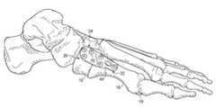
- FIG. 1Aillustrates the normal anatomical configuration of a left human foot, which includes the first metatarsal 10 that extends between the medial cuneiform 12 and the hallux 13 .
- the first metatarsal 10articulates with the medial cuneiform 12 at the first metatarsocuneiform joint 14 at its most proximal aspect; and is further connected to the hallux 13 at the metatarsophalangeal joint 15 at its most distal aspect.
- the second metatarsal 16Located adjacent (lateral) to the first metatarsal 10 is the second metatarsal 16 , which articulates with the intermediate cuneiform 17 at the second metatarsocuneiform joint 18 .
- the joint between the medial cuneiform 12 and intermediate cuneiform 17is the intermetatarsocuneiform joint 18 .
- the sesamoids 19are located beneath (plantar to) the first metatarsal head at the first MTPJ, and articulates with the head of the first metatarsal.
- FIG. 1Billustrates the resulting anatomical configuration of a human foot experiencing HAV.
- the first metatarsal 10extends from the medial cuneiform 12 and deviates medially while the hallux 13 deviates laterally.
- the sesamoids 19may rotate with the first metatarsal 10 .
- This conditionmay lead to painful motion of the big toe joint and/or difficulty fitting footwear.
- Other conditions associated with HAVmay include: hammer toe formation of the adjacent toes, forefoot pain on the ball of the foot (aka metatarsalgia), stress fractures of the adjacent metatarsals, flat feet (pes planus), and arthritis of the first MTPJ or midfoot.
- Bunionsmay occur from a variety of causes, such as genetic factors, gender influences, biomechanical and structural causes, trauma (injury), and certain shoes. Some physicians believe genetics play a large role in the development of bunions. Dudley Morton suggested that bunions may be a result of evolutionary influence, and described a certain foot type that is associated with bunions—the so called Morton's foot (a condition where the first metatarsal is shorter than the other metatarsals. See Morton DJ. The Human Foot: Its evolution, Physiology and functional Disorders. Columbia University Press, Morningside Heights, N.Y., 1935. Some people develop bunions when associated with a condition called hypermobility, where the midfoot (i.e., metatarsocuneiform joint or “MCJ,” illustrated in FIG.
- MCJmetatarsocuneiform joint
- IMAintermetatarsal angle
- HAAhallux abductus angle
- the HAAessentially measures the extent with which the hallux has deviated (laterally) from its native position (nearly rectus with the more proximal metatarsal).
- the normal value for the HAAis less than 12 degrees.
- a patient with a mild HAV deformitymay have an IMA of 10-12 degrees and an HAA of 21-30 degrees.
- a patient with a moderate HAV deformitymay have an IMA of 12-16 degrees and an HAA of 31-40 degrees.
- a patient with a severe HAV deformitymay have an IMA of greater than 16 degrees and an HAA of greater than 40 degrees.
- any osteotomy procedurereorients the first metatarsal by changing its shape from that of a straight bone to a more curved bone.
- the idea behind the Lapidus approachis to permanently fuse the base of the first metatarsal to the medial cuneiform bone in a corrected new position. This permanent fixation is carried out by first reducing the IMA and then fusing the MCJ. Implementation of this approach often involves the use of a number of screws across the joint or a plate that can accommodate screws to attach the plate to the metatarsal and medial cuneiform. In some cases, a fusion of the 1 st MCJ that incorporates lengthening of the entire segment by adding bone graft (i.e., a block of bone) into the fusion site is better termed a distraction Lapidus.
- the present disclosuregenerally relates to an improved fixation or “Lapidus” plate for use in treating HAV deformities or other conditions that may call for a fusion of this joint and possibly concomitant fusion incorporating the 2 nd metatarsal base and/or intermediate cuneiform.
- the term “Lapidus” as used hereinis only meant to be descriptive in terms of a suggested use for the plate and does not confer any structural limitations on the plate described herein.
- the Lapidus plateis used for joint arthrodesis at the first MCJ.
- the Lapidus plate according to the present disclosureprovides mechanical stability of the first metatarsal while also accommodating and assisting reorientation of the first metatarsal to correct the HAV deformity.
- the plateis generally elongated and comprises a thin and rigid stabilizing member of biocompatible material.
- the orientation of the fixation plateoffers multiplanar stability including the plantar aspects of the joint to resist tensile forces transmitted across the fusion site.
- the screw configuration of the platecan be maintained for several different sizes of the plate while still maintaining desired multiplanar stability.
- the positioning of the screw holesare designed to avoid invasion of the fusion site by the screws that ultimately pass therethrough. Indeed, the screw angles are designed for the post-Lapidus position.
- the Lapidus plate according to the present disclosureincludes additional features that accommodate the desired reorientation of the first metatarsal during correction.
- the Lapidus plate described hereinincludes a degree of twist along its longitudinal axis to follow the contour of the first metatarsal and medial cuneiform, thereby facilitating reorientation of the first metatarsal to its natural position.
- the Lapidus plateis further anatomically configured to include a recess, which accommodates the natural crests of the medial cuneiform and the first metatarsal. In this manner, the first metatarsal can be guided against the medial cuneiform and the plate such that the base of the first metatarsal fits within the recess.
- the recessthus facilitates a desired location and orientation of the first metatarsal that approximates its natural position.
- the Lapidus plate according to the present disclosureaccommodates the final position of the fusion of the MCJ.
- the fixation plateis anatomically configured to provide rigid support of the realigned MCJ fusion site while positioning screws to avoid invasion into the fusion site thus achieving desired stability. It is to be appreciated that the plate described herein can be adapted for use on both right and left feet with a right foot plate being a mirror-image of a left foot plate.
- a surgical method for preparing the MCJ for receipt of the Lapidus plate and subsequently implanting the plateis further described.
- surgical proceduresmay be concomitantly performed near the first metatarsal head.
- a capsular release of the first MTPJ and resection of the medial eminence, if present,is often performed in conjunction with release of the adductor tendon and lateral sesamoidal ligament.
- all cartilageis removed from the first MCJ with either a reciprocal saw and/or manual resection. Removal of the cartilage is preferred to allow for bone on bone contact to allow for a fusion between the medial cuneiform and first metatarsal.
- the first metatarsalis then repositioned back to its native position (IMA as close to zero as possible).
- IMAas close to zero as possible.
- the first metatarsalmust be translated inferiorly and/or angulated inferiorly (plantarflexed) to restore the weightbearing mechanics of the first metatarsal head at the ball of the foot.
- the fusion siteis stabilized with the fixation plate described herein.
- the plateis placed on the dorsal medial surface of the segment to avoid contact with muscular attachments.
- FIG. 1Aillustrates a top view of a human foot
- FIG. 1Billustrates a top view of a human foot experiencing the condition of Hallux Valgus
- FIG. 2illustrates a top view of a fixation plate according to one embodiment of the present disclosure
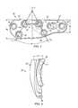
- FIG. 3Aillustrates a side view of the fixation plate of FIG. 2 ;
- FIG. 3Billustrates a side view of the fixation plate of FIG. 2 positioned adjacent to the MCJ;
- FIG. 4illustrates a schematic view depicting the gradual twist of the fixation plate of FIG. 2 ;
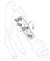
- FIG. 5Aillustrates a perspective view of the fixation plate of FIG. 2 positioned against the medial cuneiform and first metatarsal;
- FIG. 5Billustrates another perspective view of the fixation plate of FIG. 2 positioned against the medial cuneiform and first metatarsal;
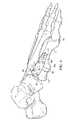
- FIG. 6illustrates a top view of the fixation plate of FIG. 2 affixed to the medial cuneiform and first metatarsal;
- FIG. 7is a bottom perspective view of the fixation plate of FIG. 6 showing the orientation of the screws.
- FIG. 8is a perspective view of another embodiment of the fixation plate wherein the plate is a distraction plate.
- FIG. 2A Lapidus plate 20 for a human left foot according to the present disclosure is illustrated in FIG. 2 . It is to be appreciated that a Lapidus plate according to the present disclosure for a human right foot would be substantially similar to and have a mirror image configuration of the plate 20 illustrated in FIG. 2 .
- the plate 20generally comprises a distal portion 22 for attachment to a metatarsal and a proximal portion 24 for attachment to a cuneiform.
- the distal and proximal portions 22 , 24are divided along a joint axis (J) generally corresponding to the fusion site (i.e., the interface between the cuneiform and metatarsal) as will be described.
- Jjoint axis
- the metatarsalis the first metatarsal 10 ( FIG. 1 ) and the cuneiform is the medial cuneiform ( FIG. 1 ).
- the plate 20is sized and shaped to conform to the anatomical contours of the first MCJ and as such the distal portion 22 includes a relatively narrow and rounded end portion 26 .
- the distal portiongradually increases in width along a first side 28 of the plate towards the proximal portion 24 .
- the proximal portion 24includes a slight gradual increase in width along the first side 28 of the plate 20 culminating in a rounded end portion 30 that is larger in width than the end portion 26 of the proximal portion 22 .
- the plate 20further includes a substantially linear second side 32 opposite the first side 28 .
- the plateis configured and designed to avoid tendon and minimize soft tissue irritation, while also providing for optimal rigidity and stability.
- the end portion 26 of the distal portion 22has an anatomically optimal width W 1 in the range of 10.5+/ ⁇ 3 mm
- the end portion 30 of the proximal portion 24has an anatomically optimal width W 2 in the range of 16+/ ⁇ 4 mm.
- the platehas a varying thickness of between 0.75 mm and 3.0 mm, thus minimizing tissue irritation.
- the edges of the platemay be tapered.
- the Lapidus plate according to the present disclosureis sized and shaped for placement in a “safe zone” of the area to be treated; that is, the place on the dorsal medial surface of the first metatarsal and medial cuneiform that is devoid of tendon attachments. It is to be appreciated that the Lapidus plate according to the present disclosure may have a configuration different than that described herein so long as the plate accommodates the contours of the particular anatomical region being treated.
- the distal and proximal portions 22 , 24 of the plate 20each include a plurality of screw holes formed therethrough to facilitate attachment of the plate to the respective metatarsal and cuneiform.
- the distal portion 22includes four screw holes formed through the plate 20 with two holes 40 , 42 being positioned in proximity to the joint axis J and the remaining two holes 44 , 46 being positioned distal of holes 40 , 42 .
- the holes 40 , 42 and 46are countersunk and threaded to accommodate screws having threaded heads as will be described. Hole 40 is positioned adjacent to the second side 32 and the joint axis J while hole 42 is positioned distal of hole 40 and closer to side 28 of the plate 20 .
- Hole 44is positioned distally of holes 40 , 42 and is generally elongated to accommodate movement of the plate 20 as will be described.
- the elongated nature of hole 44defines a pair of substantially parallel sides 47 , 49 , which are substantially parallel to second side 32 of the plate 20 .
- Hole 46is positioned distal of hole 44 and also accommodates a screw (not shown) to assist with fixation of the plate 20 to the metatarsal. The location of hole 46 assists with distributing weight away from the fusion site.
- the proximal portion 24includes a plurality of screw holes to accommodate fixation.
- the proximal portion 24 of the plate 20includes three holes 48 , 50 and 52 formed therethrough.
- the holes 48 , 50 and 52are countersunk and threaded to accommodate screws having threaded heads as will be described.
- Hole 48generally corresponds to hole 40 of the metatarsal portion, and as such, is positioned adjacent to the second side 32 and the joint axis J.
- Hole 50generally corresponds to hole 42 of the metatarsal portion, and as such, is positioned proximal of hole 48 and closer to side 28 of the plate 20 .
- Hole 52is positioned proximal of holes 48 , 50 and accommodates a screw (not shown) to assist with fixation of the plate 20 to the cuneiform bone. The location of hole 52 assists with distributing weight away from the fusion site.
- the holes 40 , 42 of the distal portion 22 and the holes 48 , 50 of the proximal portionare designed to assist with screw fixation into the widest part of both bone segments while maintaining a safe distance from the fusion site such that the screws that ultimately pass through such holes do not penetrate the fusion site.
- the holes 40 , 42 , 48 and 50form a substantially trapezoidal shape, which facilitates the even distribution of load across the MCJ. It is to be appreciated that the arrangement of holes 40 , 42 , 48 and 50 may not form an exact trapezoid.
- the line defined from the centerpoint of hole 40 to the centerpoint of hole 48 and the line defined from the centerpoint of hole 42 to the centerpoint of hole 50may not be perfectly parallel.
- the arrangement of holes 40 , 42 , 48 and 50may form a substantially trapezoidal shape rather than a true trapezoidal shape.
- the substantially trapezoidal arrangement of the holes 40 , 42 , 48 and 50define an angle ⁇ measured between the non-parallel sides of the trapezoid (i.e., between the lines A 1 and A 2 shown for purposes of illustration in FIG. 2 ).
- the distance between the dorsal screw holes 40 , 48is measured by the distance D.
- the angle ⁇is optimally 57+/ ⁇ 15 degrees and the distance between the dorsal screws 40 , 48 is optimally 12+/ ⁇ 4 mm.
- the plate 20further includes a recess 60 defined along a bone-contacting surface 62 of the plate.
- the recess 60is generally defined at and adjacent to the joint axis J of the plate 20 .
- the plate 20is designed to accommodate the crests of the first metatarsal 10 and medial cuneiform 12 upon placement of the plate against the MCJ as illustrated in FIG. 3B .
- a channel 64is formed laterally in the bone-contacting side of the plate 20 in a region generally corresponding to the recess 60 to facilitate additional flexibility at the fusion site along the joint axis J ( FIG. 2 ). This flexibility assists the surgeon with bending of the plate 20 to achieve the desired final position of the plate at the fusion site.
- the plate 20includes a degree of twist along its longitudinal axis (i.e., from end portion 30 to end portion 26 as shown in FIG. 2 ). Referring to FIG. 4 , the plate 20 has a gradual twist ⁇ from proximal portion 24 to distal portion 22 . In some embodiments, the anatomically optimal twist is 12+/ ⁇ 6 degrees measured along the longitudinal axis of the plate 20 defined from end portion 30 to end portion 26 .
- the first MCJis prepared for plate implantation by first performing a capsulotomy of the ligaments surrounding the first MCJ and then removing cartilage within this joint.
- the proximal portion 24 of the plate 20is placed against the medial cuneiform 12 and attached thereto using screws 70 having threaded heads and threaded shafts.
- the threaded heads of the screws 70thread into the corresponding countersunk threaded holes 48 , 50 and 52 ( FIG. 2 ) such that the screws are fixed relative to the plate 20 .
- the screwsmay have non-threaded heads such that the screws are not locked into place relative to the plate 20 .
- the first metatarsal 10Upon attachment of the plate 20 to the medial cuneiform 12 , the first metatarsal 10 is translated inferiorly in the direction I as illustrated in FIG. 5B to maintain a natural distribution of ground force over all the foot's sesamoid bones to avoid stress fracture or even breakage of the other four metatarsals.
- the optimal amount of translation D Iis 3+/ ⁇ 3 mm to accommodate for the shortening that occurs when cartilage is removed from the joint.
- the first metatarsal 10is also translated laterally and rotated in the direction R to return the metatarsal to its approximate natural anatomic orientation to reduce the intermetatarsal angle.
- the plate 20 according to the present disclosureis designed for placement against the medial cuneiform and first metatarsal in an area devoid of muscular and tendinous attachments.
- the MCJmay be temporarily fixated in a corrected position using a k-wire.
- the plate 20may include k-wire holes such that k-wires can be used in conjunction with the plate to stabilize the first metatarsal for screw implantation.
- the first metatarsal 10is then moved toward the medial cuneiform 12 whereupon the screw positioned through elongated hole 44 is tightened to compress the first MCJ.
- the distal portion 22 of the plate 20is further attached to the metatarsal using threaded screws 70 having threaded heads that are placed through screw holes 40 , 42 and 46 ( FIG. 2 ) and into the bone.
- the threaded heads of the screws 70thread into the corresponding countersunk threaded holes 40 , 42 and 46 such that the screws are fixed relative to the plate 20 .
- the screwsmay have non-threaded heads such that the screws are not locked into place relative to the plate 20 .
- the twist of the plate 20 along its longitudinal axisfacilitates desired orientation of the screws into the metatarsal. More specifically, holes 40 and 42 are angled toward one another such that implantation of the screws 70 through these holes results in their axes crossing one another in a divergent manner. This, in turn, provides for optimal orientation of the screws 70 in the first metatarsal 10 to achieve desired stability.
- a variation of the Lapidus plate according to the present disclosureinvolves providing for distraction (or lengthening) at the fusion site. As illustrated in FIG. 8 , this allows for bone graft 80 to be interposed between the 1 st metatarsal base 10 b and the medial cuneiform 12 , when the clinical situation arises.
- Providing for distraction at the fusion sitemaintains that the screw holes 40 and 42 purchase the 1 st metatarsal base 10 b , for which these holes are configured to provide maximal stability at the fusion site.
- the amount of distraction D′ most commonly requiredis between 1 mm-25 mm, with the distraction plate accommodating this length. It is to be appreciated, however, that other distraction lengths may be accommodated by the plate 20 of the present disclosure.
- the plate 20may add length by providing additional screw holes formed in distal portion 22 of the plate 20 .
- fixation of the platemay occur via a screw passing through the fusion site into the intermediate cuneiform and/or second metatarsal.
- the Lapidus plate 20 described herein and associated method of implantationleads to fusion of the MCJ, which provides for mechanical stability of the first metatarsal and medial cuneiform and the reorientation to compensate for an HAV deformity.
- the orientation of the fixation achieved according to the principles of the present disclosureoffers multiplanar stability including the plantar aspects of the MCJ to resist tensile forces across the fusion site.
- the screw configuration described hereincan thus be maintained for several different sizes of distraction Lapidus arthrodesis. That is, the screw configuration provides multiplanar stability as distraction length is added to the plate 20 .
Landscapes
- Health & Medical Sciences (AREA)
- Orthopedic Medicine & Surgery (AREA)
- Surgery (AREA)
- Life Sciences & Earth Sciences (AREA)
- Heart & Thoracic Surgery (AREA)
- Nuclear Medicine, Radiotherapy & Molecular Imaging (AREA)
- Engineering & Computer Science (AREA)
- Biomedical Technology (AREA)
- Neurology (AREA)
- Medical Informatics (AREA)
- Molecular Biology (AREA)
- Animal Behavior & Ethology (AREA)
- General Health & Medical Sciences (AREA)
- Public Health (AREA)
- Veterinary Medicine (AREA)
- Surgical Instruments (AREA)
- Orthopedics, Nursing, And Contraception (AREA)
Abstract
Description
Claims (20)
Priority Applications (7)
| Application Number | Priority Date | Filing Date | Title |
|---|---|---|---|
| US12/274,199US8828063B2 (en) | 2008-11-19 | 2008-11-19 | Fixation plate for use in the Lapidus approach |
| AU2009316867AAU2009316867B2 (en) | 2008-11-19 | 2009-11-12 | Fixation plate for use in the Lapidus approach |
| JP2011537509AJP5539375B2 (en) | 2008-11-19 | 2009-11-12 | Fixed plate used in the rapidus approach |
| PCT/US2009/064150WO2010059497A1 (en) | 2008-11-19 | 2009-11-12 | Fixation plate for use in the lapidus approach |
| EP09828045.6AEP2355731B1 (en) | 2008-11-19 | 2009-11-12 | Fixation plate for use in the lapidus approach |
| ES09828045.6TES2528243T3 (en) | 2008-11-19 | 2009-11-12 | Fixing plate for use in the Lapidus procedure |
| US14/480,309US9107715B2 (en) | 2008-11-19 | 2014-09-08 | Fixation plate for use in the lapidus approach |
Applications Claiming Priority (1)
| Application Number | Priority Date | Filing Date | Title |
|---|---|---|---|
| US12/274,199US8828063B2 (en) | 2008-11-19 | 2008-11-19 | Fixation plate for use in the Lapidus approach |
Related Child Applications (1)
| Application Number | Title | Priority Date | Filing Date |
|---|---|---|---|
| US14/480,309ContinuationUS9107715B2 (en) | 2008-11-19 | 2014-09-08 | Fixation plate for use in the lapidus approach |
Publications (2)
| Publication Number | Publication Date |
|---|---|
| US20100125300A1 US20100125300A1 (en) | 2010-05-20 |
| US8828063B2true US8828063B2 (en) | 2014-09-09 |
Family
ID=42172615
Family Applications (2)
| Application Number | Title | Priority Date | Filing Date |
|---|---|---|---|
| US12/274,199Active2030-09-13US8828063B2 (en) | 2008-11-19 | 2008-11-19 | Fixation plate for use in the Lapidus approach |
| US14/480,309ActiveUS9107715B2 (en) | 2008-11-19 | 2014-09-08 | Fixation plate for use in the lapidus approach |
Family Applications After (1)
| Application Number | Title | Priority Date | Filing Date |
|---|---|---|---|
| US14/480,309ActiveUS9107715B2 (en) | 2008-11-19 | 2014-09-08 | Fixation plate for use in the lapidus approach |
Country Status (6)
| Country | Link |
|---|---|
| US (2) | US8828063B2 (en) |
| EP (1) | EP2355731B1 (en) |
| JP (1) | JP5539375B2 (en) |
| AU (1) | AU2009316867B2 (en) |
| ES (1) | ES2528243T3 (en) |
| WO (1) | WO2010059497A1 (en) |
Cited By (15)
| Publication number | Priority date | Publication date | Assignee | Title |
|---|---|---|---|---|
| US9408647B2 (en) | 2014-02-27 | 2016-08-09 | Biomedical Enterprises, Inc. | Method and apparatus for use of a compressing plate |
| WO2017031000A1 (en)* | 2015-08-14 | 2017-02-23 | Treace Medical Concepts, Inc. | Bone positioning and preparing guide systems and methods |
| US9883897B2 (en) | 2014-09-25 | 2018-02-06 | Biomedical Enterprises, Inc. | Method and apparatus for a compressing plate |
| US10245086B2 (en) | 2015-02-18 | 2019-04-02 | Treace Medical Concepts, Inc. | Bone plating kit for foot and ankle applications |
| US10245088B2 (en) | 2015-01-07 | 2019-04-02 | Treace Medical Concepts, Inc. | Bone plating system and method |
| KR20200045864A (en) | 2018-10-23 | 2020-05-06 | 한림대학교 산학협력단 | Open wedge osteotomy device for correction of hallux valgus |
| US11426219B2 (en) | 2015-05-06 | 2022-08-30 | Treace Medical Concepts, Inc. | Intra-osseous plate system and method |
| US11583323B2 (en) | 2018-07-12 | 2023-02-21 | Treace Medical Concepts, Inc. | Multi-diameter bone pin for installing and aligning bone fixation plate while minimizing bone damage |
| US11883075B2 (en) | 2021-11-08 | 2024-01-30 | Relja Innovations, Llc | Device and surgical technique for foot surgery |
| US11890039B1 (en) | 2019-09-13 | 2024-02-06 | Treace Medical Concepts, Inc. | Multi-diameter K-wire for orthopedic applications |
| US11931106B2 (en) | 2019-09-13 | 2024-03-19 | Treace Medical Concepts, Inc. | Patient-specific surgical methods and instrumentation |
| US11986251B2 (en) | 2019-09-13 | 2024-05-21 | Treace Medical Concepts, Inc. | Patient-specific osteotomy instrumentation |
| US12161371B2 (en) | 2021-01-18 | 2024-12-10 | Treace Medical Concepts, Inc. | Contoured bone plate with locking screw for bone compression, particularly across a tarsometatarsal joint |
| USD1065530S1 (en) | 2019-12-12 | 2025-03-04 | Relja Innovations Llc | Surgical apparatus for minimally invasive surgical procedures |
| US12440250B2 (en) | 2024-02-05 | 2025-10-14 | Treace Medical Concepts, Inc. | Multi-diameter K-wire for orthopedic applications |
Families Citing this family (57)
| Publication number | Priority date | Publication date | Assignee | Title |
|---|---|---|---|---|
| US8021402B2 (en)* | 2006-03-07 | 2011-09-20 | Orthohelix Surgical Designs, Inc. | Distal radius plate |
| FR2936700B1 (en) | 2008-10-02 | 2012-04-13 | Memometal Technologies | ORTHOPEDIC IMPLANT IN THE FORM OF A PLATE TO BE FIXED BETWEEN TWO BONE PARTS |
| US20100256687A1 (en) | 2009-04-01 | 2010-10-07 | Merete Medical Gmbh | Fixation Device and Method of Use for a Ludloff Osteotomy Procedure |
| DE102009016394B4 (en) | 2009-04-07 | 2016-02-11 | Merete Medical Gmbh | Device for stable-angle fixation and compression of a fracture site or osteotomy on a bone |
| EP2515779B1 (en) | 2009-12-22 | 2016-03-02 | Merete Medical GmbH | Bone plate system for osteosynthesis |
| US20120065689A1 (en)* | 2010-09-10 | 2012-03-15 | Priya Prasad | Joint Fusion Construct And Method |
| US9005255B2 (en) | 2011-02-15 | 2015-04-14 | Orthohelix Surgical Designs, Inc. | Orthopedic compression plate |
| RU2509539C2 (en)* | 2011-07-01 | 2014-03-20 | Федеральное Государственное Учреждение "Научно-Исследовательский Детский Ортопедический Институт Имени Г.И. Турнера" Министерства Здравоохранения И Социального Развития Российской Федерации | Method of treating hallux valgus |
| DE202011051165U1 (en) | 2011-08-31 | 2011-11-14 | Merete Medical Gmbh | Anatomically adapted, plantar bone plate and bone plate system |
| US9060822B2 (en) | 2011-12-28 | 2015-06-23 | Orthohelix Surgical Designs, Inc. | Orthopedic compression plate and method of surgery |
| US9149309B2 (en) | 2012-03-23 | 2015-10-06 | Yale University | Systems and methods for sketching designs in context |
| DE102012103894B4 (en) | 2012-05-03 | 2016-10-27 | Merete Medical Gmbh | Bone plate system for osteosynthesis |
| US9907588B2 (en) | 2012-09-06 | 2018-03-06 | Orthohelix Surgical Designs, Inc. | Orthopedic dual pocket compression plate and method of surgery |
| EP2937050A4 (en)* | 2012-12-19 | 2016-08-17 | Ind Medicas Sampedro S A S | Minimally invasive fixation plate for the correction of bunions |
| US9545276B2 (en) | 2013-03-15 | 2017-01-17 | Aristotech Industries Gmbh | Fixation device and method of use for a lapidus-type plantar hallux valgus procedure |
| FR3006163B1 (en) | 2013-05-29 | 2016-03-25 | Fx Solutions | HUMERAL PLATE |
| USD745162S1 (en) | 2014-01-27 | 2015-12-08 | Merete Medical Gmbh | Bone plate |
| US20150335365A1 (en)* | 2014-05-24 | 2015-11-26 | Neutin Orthopedics, LLC | Fixation device for a mau-type osteotomy procedure |
| US20160015426A1 (en) | 2014-07-15 | 2016-01-21 | Treace Medical Concepts, Inc. | Bone positioning and cutting system and method |
| AU2014321174B2 (en)* | 2014-09-11 | 2017-06-29 | Wright Medical Technology, Inc. | Medial-plantar plate for medial column arthrodesis |
| US9763705B2 (en)* | 2014-10-03 | 2017-09-19 | Globus Medical, Inc. | Orthopedic stabilization devices and methods for installation thereof |
| US9980760B2 (en)* | 2014-11-19 | 2018-05-29 | Paragon 28, Inc. | Step off bone plates, systems, and methods of use |
| US20160175089A1 (en)* | 2014-12-22 | 2016-06-23 | First Ray, LLC | Correction of first ray deformity via peroneus longus tendon modification |
| US9687250B2 (en) | 2015-01-07 | 2017-06-27 | Treace Medical Concepts, Inc. | Bone cutting guide systems and methods |
| CN104510523A (en)* | 2015-01-12 | 2015-04-15 | 上海斯地德商务咨询中心 | Cross-navicular cuneiform second tarsometatarsal joint back side plate |
| CN104490460A (en)* | 2015-01-13 | 2015-04-08 | 上海斯地德商务咨询中心 | First tread wedge joint plate |
| WO2016134154A1 (en) | 2015-02-18 | 2016-08-25 | Treace Medical Concepts, Inc. | Pivotable bone cutting guide useful for bone realignment and compression techniques |
| US10376268B2 (en) | 2015-02-19 | 2019-08-13 | First Ray, LLC | Indexed tri-planar osteotomy guide and method |
| EP4483824A3 (en) | 2015-07-14 | 2025-03-05 | Treace Medical Concepts, Inc. | Bone positioning guide |
| US10849663B2 (en) | 2015-07-14 | 2020-12-01 | Treace Medical Concepts, Inc. | Bone cutting guide systems and methods |
| EP4494582A3 (en) | 2015-08-14 | 2025-04-16 | Treace Medical Concepts, Inc. | Tarsal-metatarsal joint procedure utilizing fulcrum |
| WO2017031020A1 (en) | 2015-08-14 | 2017-02-23 | Treace Medical Concepts, Inc. | Tarsal-metatarsal joint procedure utilizing fulcrum |
| CA2998481C (en) | 2015-09-18 | 2024-05-14 | Treace Medical Concepts, Inc. | Joint spacer systems and methods |
| CN109922741B (en)* | 2016-06-02 | 2022-11-08 | 联骨美国有限责任公司 | Foot sole bone fusion plate |
| US10512470B1 (en) | 2016-08-26 | 2019-12-24 | Treace Medical Concepts, Inc. | Osteotomy procedure for correcting bone misalignment |
| US10610273B2 (en)* | 2016-11-07 | 2020-04-07 | In2Bones Usa, Llc | Bone plate with transverse screw |
| US10524808B1 (en) | 2016-11-11 | 2020-01-07 | Treace Medical Concepts, Inc. | Devices and techniques for performing an osteotomy procedure on a first metatarsal to correct a bone misalignment |
| US10939939B1 (en) | 2017-02-26 | 2021-03-09 | Treace Medical Concepts, Inc. | Fulcrum for tarsal-metatarsal joint procedure |
| US11596443B2 (en) | 2018-07-11 | 2023-03-07 | Treace Medical Concepts, Inc. | Compressor-distractor for angularly realigning bone portions |
| US11607250B2 (en) | 2019-02-13 | 2023-03-21 | Treace Medical Concepts, Inc. | Tarsal-metatarsal joint procedure utilizing compressor-distractor and instrument providing sliding surface |
| WO2021021640A1 (en) | 2019-07-26 | 2021-02-04 | Crossroads Extremity Systems, Llc | Bone repositioning guide system and procedure |
| CA3146564A1 (en) | 2019-08-07 | 2021-02-11 | Jason May | Bi-planar instrument for bone cutting and joint realignment procedure |
| US11889998B1 (en) | 2019-09-12 | 2024-02-06 | Treace Medical Concepts, Inc. | Surgical pin positioning lock |
| WO2021155269A1 (en) | 2020-01-31 | 2021-08-05 | Treace Medical Concepts, Inc. | Metatarsophalangeal joint preparation and metatarsal realignment for fusion |
| JP7639014B2 (en)* | 2020-02-19 | 2025-03-04 | クロスローズ エクストリミティ システムズ リミテッド ライアビリティ カンパニー | Systems and methods for lapidus bunion repair |
| AU2021275140A1 (en) | 2020-05-19 | 2023-02-02 | Treace Medical Concepts, Inc. | Devices and techniques for treating metatarsus adductus |
| US12310603B2 (en) | 2021-02-18 | 2025-05-27 | Treace Medical Concepts, Inc. | System and technique for metatarsal realignment with reduced incision length |
| AU2022276540A1 (en) | 2021-05-20 | 2023-11-30 | Treace Medical Concepts, Inc. | Cut guide with integrated joint realignment features |
| USD1079011S1 (en) | 2022-02-23 | 2025-06-10 | Treace Medical Concepts, Inc. | Metatarsal cut guide with parallel cut faces |
| USD1075012S1 (en) | 2022-02-23 | 2025-05-13 | Treace Medical Concepts, Inc. | Metatarsal lateral release instrument |
| USD1051382S1 (en) | 2022-02-23 | 2024-11-12 | Treace Medical Concepts, Inc. | Lesser metatarsal cut guide |
| USD1011524S1 (en) | 2022-02-23 | 2024-01-16 | Treace Medical Concepts, Inc. | Compressor-distractor for the foot |
| AU2023223468A1 (en)* | 2022-02-23 | 2024-09-12 | Treace Medical Concepts, Inc. | First metatarsal lateral release instrument and technique |
| USD1057155S1 (en) | 2022-02-23 | 2025-01-07 | Treace Medical Concepts, Inc. | Lesser metatarsal cut guide with parallel cut faces |
| WO2024025903A1 (en)* | 2022-07-28 | 2024-02-01 | In2Bones Usa, Llc | Bone plate for treating first tarsal metatarsal lisfranc injuries |
| USD1068077S1 (en) | 2023-02-08 | 2025-03-25 | Treace Medical Concepts, Inc. | Orthopedic rasp for preparing an intercuneiform joint |
| USD1068078S1 (en) | 2023-02-08 | 2025-03-25 | Treace Medical Concepts, Inc. | Handle for an orthopedic instrument |
Citations (13)
| Publication number | Priority date | Publication date | Assignee | Title |
|---|---|---|---|---|
| US4159716A (en) | 1977-10-17 | 1979-07-03 | Borchers Clinton H | Method of compressing and realigning bone structures to correct splay foot |
| US6206882B1 (en)* | 1999-03-30 | 2001-03-27 | Surgical Dynamics Inc. | Plating system for the spine |
| US6344042B1 (en) | 1998-05-12 | 2002-02-05 | Synthes (Usa) | Bone augmentation device |
| US20020128654A1 (en) | 1998-02-18 | 2002-09-12 | Steger Shon D. | Method and apparatus for bone fracture fixation |
| US20050065521A1 (en) | 2002-02-22 | 2005-03-24 | Steger Shon D. | Method and apparatus for bone fracture fixation |
| US20050234458A1 (en)* | 2004-04-19 | 2005-10-20 | Huebner Randall J | Expanded stabilization of bones |
| US20060173459A1 (en) | 2005-01-28 | 2006-08-03 | Kay David B | Orthopedic plate for use in small bone repair |
| JP2006280949A (en) | 2005-03-31 | 2006-10-19 | Depuy Products Inc | Plate for fixing mid-foot |
| JP2006280951A (en) | 2005-03-31 | 2006-10-19 | Depuy Products Inc | Plate for uniting metatarsophalangeal joint |
| US20060241607A1 (en)* | 2005-03-31 | 2006-10-26 | Mark Myerson | Metatarsal fixation plate |
| US20070239163A1 (en)* | 2006-03-07 | 2007-10-11 | Strnad Lee A | Orthopedic Plate |
| US20070265629A1 (en)* | 2006-03-07 | 2007-11-15 | Amanda Martin | Distal radius plate |
| FR2905590A1 (en) | 2006-09-11 | 2008-03-14 | Surge Foot | ARTHRODESIS PLATE OF A METATARSO-PHALANGEAL ARTICULATION. |
- 2008
- 2008-11-19USUS12/274,199patent/US8828063B2/enactiveActive
- 2009
- 2009-11-12WOPCT/US2009/064150patent/WO2010059497A1/enactiveApplication Filing
- 2009-11-12JPJP2011537509Apatent/JP5539375B2/enactiveActive
- 2009-11-12AUAU2009316867Apatent/AU2009316867B2/ennot_activeCeased
- 2009-11-12ESES09828045.6Tpatent/ES2528243T3/enactiveActive
- 2009-11-12EPEP09828045.6Apatent/EP2355731B1/enactiveActive
- 2014
- 2014-09-08USUS14/480,309patent/US9107715B2/enactiveActive
Patent Citations (17)
| Publication number | Priority date | Publication date | Assignee | Title |
|---|---|---|---|---|
| US4159716A (en) | 1977-10-17 | 1979-07-03 | Borchers Clinton H | Method of compressing and realigning bone structures to correct splay foot |
| US20020128654A1 (en) | 1998-02-18 | 2002-09-12 | Steger Shon D. | Method and apparatus for bone fracture fixation |
| US7052499B2 (en) | 1998-02-18 | 2006-05-30 | Walter Lorenz Surgical, Inc. | Method and apparatus for bone fracture fixation |
| US6344042B1 (en) | 1998-05-12 | 2002-02-05 | Synthes (Usa) | Bone augmentation device |
| US6206882B1 (en)* | 1999-03-30 | 2001-03-27 | Surgical Dynamics Inc. | Plating system for the spine |
| US20050065521A1 (en) | 2002-02-22 | 2005-03-24 | Steger Shon D. | Method and apparatus for bone fracture fixation |
| US20050234458A1 (en)* | 2004-04-19 | 2005-10-20 | Huebner Randall J | Expanded stabilization of bones |
| US20060173459A1 (en) | 2005-01-28 | 2006-08-03 | Kay David B | Orthopedic plate for use in small bone repair |
| JP2006280949A (en) | 2005-03-31 | 2006-10-19 | Depuy Products Inc | Plate for fixing mid-foot |
| JP2006280951A (en) | 2005-03-31 | 2006-10-19 | Depuy Products Inc | Plate for uniting metatarsophalangeal joint |
| US20060241607A1 (en)* | 2005-03-31 | 2006-10-26 | Mark Myerson | Metatarsal fixation plate |
| US20060241608A1 (en)* | 2005-03-31 | 2006-10-26 | Mark Myerson | Plate for fusion of the metatarso-phalangeal joint |
| US20060241592A1 (en)* | 2005-03-31 | 2006-10-26 | Mark Myerson | Mid-foot fixation plate |
| US7344538B2 (en) | 2005-03-31 | 2008-03-18 | Depuy Products, Inc. | Mid-foot fixation plate |
| US20070239163A1 (en)* | 2006-03-07 | 2007-10-11 | Strnad Lee A | Orthopedic Plate |
| US20070265629A1 (en)* | 2006-03-07 | 2007-11-15 | Amanda Martin | Distal radius plate |
| FR2905590A1 (en) | 2006-09-11 | 2008-03-14 | Surge Foot | ARTHRODESIS PLATE OF A METATARSO-PHALANGEAL ARTICULATION. |
Non-Patent Citations (7)
| Title |
|---|
| Australian Examination Report, AU Application No. 2009316867, dated Mar. 20, 2014, 3 pages. |
| Communication pursuant to Article 94(3) EPC, EP Application No. 09828045.6, dated Jun. 11, 2013, 5 pages. |
| Communication pursuant to Article 94(3) EPC, EP Application No. 09828045.6, dated Oct. 5, 2012, 5 pages. |
| International Search Report of corresponding PCT application No. PCT/US2009/064150. |
| Japanese Office Action, dated Oct. 1, 2013, JP Application No. 2011-537509, 6 pages. |
| Morton, D.J., "The Human Foot: Its Evolution, Physiology and Functional Disorders," Columbia University Press, Morningside Heights, N.Y., 1935, Abstract provided. |
| Supplementary Partial European Search Report of corresponding European Patent Application No. EP09828045. |
Cited By (25)
| Publication number | Priority date | Publication date | Assignee | Title |
|---|---|---|---|---|
| US9408647B2 (en) | 2014-02-27 | 2016-08-09 | Biomedical Enterprises, Inc. | Method and apparatus for use of a compressing plate |
| US9883897B2 (en) | 2014-09-25 | 2018-02-06 | Biomedical Enterprises, Inc. | Method and apparatus for a compressing plate |
| US10245088B2 (en) | 2015-01-07 | 2019-04-02 | Treace Medical Concepts, Inc. | Bone plating system and method |
| US11154340B2 (en) | 2015-01-07 | 2021-10-26 | Treace Medical Concepts, Inc. | Bone plating system and method |
| US12059185B2 (en) | 2015-01-07 | 2024-08-13 | Treace Medical Concepts, Inc. | Bone plating system and method |
| US10245086B2 (en) | 2015-02-18 | 2019-04-02 | Treace Medical Concepts, Inc. | Bone plating kit for foot and ankle applications |
| US11344347B2 (en) | 2015-02-18 | 2022-05-31 | Treace Medical Concepts, Inc. | Bone plating kit for foot and ankle applications |
| US11969193B2 (en)* | 2015-05-06 | 2024-04-30 | Treace Medical Concepts, Inc. | Intra-osseous plate system and method |
| US12396771B2 (en)* | 2015-05-06 | 2025-08-26 | Treace Medical Concepts, Inc. | Intra-osseous plate system and method |
| US20240277389A1 (en)* | 2015-05-06 | 2024-08-22 | Treace Medical Concepts, Inc. | Intra-osseous plate system and method |
| US11426219B2 (en) | 2015-05-06 | 2022-08-30 | Treace Medical Concepts, Inc. | Intra-osseous plate system and method |
| US20220409250A1 (en)* | 2015-05-06 | 2022-12-29 | Treace Medical Concepts, Inc. | Intra-osseous plate system and method |
| AU2016308461B2 (en)* | 2015-08-14 | 2021-05-20 | Treace Medical Concepts, Inc. | Bone positioning and preparing guide systems and methods |
| AU2021218092B2 (en)* | 2015-08-14 | 2023-08-17 | Treace Medical Concepts, Inc. | Bone positioning and preparing guide systems and methods |
| WO2017031000A1 (en)* | 2015-08-14 | 2017-02-23 | Treace Medical Concepts, Inc. | Bone positioning and preparing guide systems and methods |
| US11583323B2 (en) | 2018-07-12 | 2023-02-21 | Treace Medical Concepts, Inc. | Multi-diameter bone pin for installing and aligning bone fixation plate while minimizing bone damage |
| KR20200045864A (en) | 2018-10-23 | 2020-05-06 | 한림대학교 산학협력단 | Open wedge osteotomy device for correction of hallux valgus |
| US11890039B1 (en) | 2019-09-13 | 2024-02-06 | Treace Medical Concepts, Inc. | Multi-diameter K-wire for orthopedic applications |
| US11931106B2 (en) | 2019-09-13 | 2024-03-19 | Treace Medical Concepts, Inc. | Patient-specific surgical methods and instrumentation |
| US11986251B2 (en) | 2019-09-13 | 2024-05-21 | Treace Medical Concepts, Inc. | Patient-specific osteotomy instrumentation |
| USD1065530S1 (en) | 2019-12-12 | 2025-03-04 | Relja Innovations Llc | Surgical apparatus for minimally invasive surgical procedures |
| US12295589B2 (en) | 2019-12-12 | 2025-05-13 | Relja Innovations, Llc | Method, surgical apparatus, and surgical implant for minimally invasive surgical procedures |
| US12161371B2 (en) | 2021-01-18 | 2024-12-10 | Treace Medical Concepts, Inc. | Contoured bone plate with locking screw for bone compression, particularly across a tarsometatarsal joint |
| US11883075B2 (en) | 2021-11-08 | 2024-01-30 | Relja Innovations, Llc | Device and surgical technique for foot surgery |
| US12440250B2 (en) | 2024-02-05 | 2025-10-14 | Treace Medical Concepts, Inc. | Multi-diameter K-wire for orthopedic applications |
Also Published As
| Publication number | Publication date |
|---|---|
| US9107715B2 (en) | 2015-08-18 |
| JP5539375B2 (en) | 2014-07-02 |
| AU2009316867B2 (en) | 2015-04-30 |
| US20100125300A1 (en) | 2010-05-20 |
| EP2355731A4 (en) | 2012-03-28 |
| US20140379036A1 (en) | 2014-12-25 |
| JP2012509143A (en) | 2012-04-19 |
| AU2009316867A1 (en) | 2010-05-27 |
| EP2355731B1 (en) | 2014-10-22 |
| WO2010059497A1 (en) | 2010-05-27 |
| EP2355731A1 (en) | 2011-08-17 |
| ES2528243T3 (en) | 2015-02-05 |
Similar Documents
| Publication | Publication Date | Title |
|---|---|---|
| US9107715B2 (en) | Fixation plate for use in the lapidus approach | |
| US11974760B2 (en) | Opening and closing wedge osteotomy guide and method | |
| US12268424B2 (en) | Osteotomy plate, plate driver and method for their use | |
| US12016600B2 (en) | Orthopedic compression plate and method of surgery | |
| Tennant et al. | Calcaneus osteotomy | |
| US8784457B2 (en) | Implant for correcting skeletal mechanics | |
| US8257403B2 (en) | Orthopedic plate for use in the midfoot | |
| JP2006280952A (en) | Plate for fixing metatarsal bone | |
| IL196257A (en) | Calcaneal plate | |
| Boffeli et al. | Modified Dwyer osteotomy with rotation and reinsertion of autograft bone wedge for residual heel deformity despite previous delayed subtalar joint arthrodesis after calcaneal fracture | |
| Van Aman et al. | Subtalar arthroereisis as adjunct treatment for type II posterior tibial tendon deficiency | |
| Vora et al. | The medial approach to triple arthrodesis: indications and technique for management of rigid valgus deformities in high-risk patients | |
| Aiyer et al. | Tendon transfers for hallux varus | |
| Tendon | Addressing Stage II |
Legal Events
| Date | Code | Title | Description |
|---|---|---|---|
| AS | Assignment | Owner name:AMEI TECHNOLOGIES, INC.,DELAWARE Free format text:ASSIGNMENT OF ASSIGNORS INTEREST;ASSIGNORS:BLITZ, NEAL;GEORGE, MICHAEL;SIGNING DATES FROM 20080623 TO 20081104;REEL/FRAME:021871/0996 Owner name:AMEI TECHNOLOGIES, INC., DELAWARE Free format text:ASSIGNMENT OF ASSIGNORS INTEREST;ASSIGNORS:BLITZ, NEAL;GEORGE, MICHAEL;SIGNING DATES FROM 20080623 TO 20081104;REEL/FRAME:021871/0996 | |
| AS | Assignment | Owner name:JPMORGAN CHASE BANK, N.A., AS ADMINISTRATIVE AGENT Free format text:SECURITY AGREEMENT;ASSIGNORS:AMEI TECHNOLOGIES, INC.;ORTHOFIX, INC.;REEL/FRAME:025406/0511 Effective date:20100830 | |
| STCF | Information on status: patent grant | Free format text:PATENTED CASE | |
| AS | Assignment | Owner name:JPMORGAN CHASE BANK, N.A., AS ADMINISTRATIVE AGENT Free format text:SECURITY INTEREST;ASSIGNOR:AMEI TECHNOLOGIES INC.;REEL/FRAME:036649/0821 Effective date:20150831 Owner name:AMEI TECHNOLOGIES, INC., TEXAS Free format text:RELEASE BY SECURED PARTY;ASSIGNOR:JPMORGAN CHASE BANK, N.A., AS ADMINISTRATIVE AGENT;REEL/FRAME:036676/0232 Effective date:20150830 Owner name:ORTHOFIX, INC., TEXAS Free format text:RELEASE BY SECURED PARTY;ASSIGNOR:JPMORGAN CHASE BANK, N.A., AS ADMINISTRATIVE AGENT;REEL/FRAME:036676/0232 Effective date:20150830 | |
| MAFP | Maintenance fee payment | Free format text:PAYMENT OF MAINTENANCE FEE, 4TH YEAR, LARGE ENTITY (ORIGINAL EVENT CODE: M1551) Year of fee payment:4 | |
| AS | Assignment | Owner name:ORTHOFIX S.R.L., ITALY Free format text:ASSIGNMENT OF ASSIGNORS INTEREST;ASSIGNOR:AMEI TECHNOLOGIES INC.;REEL/FRAME:047502/0769 Effective date:20171219 | |
| MAFP | Maintenance fee payment | Free format text:PAYMENT OF MAINTENANCE FEE, 8TH YEAR, LARGE ENTITY (ORIGINAL EVENT CODE: M1552); ENTITY STATUS OF PATENT OWNER: LARGE ENTITY Year of fee payment:8 |