US8828061B2 - Vertebral stabilization devices and associated surgical methods - Google Patents
Vertebral stabilization devices and associated surgical methodsDownload PDFInfo
- Publication number
- US8828061B2 US8828061B2US12/051,202US5120208AUS8828061B2US 8828061 B2US8828061 B2US 8828061B2US 5120208 AUS5120208 AUS 5120208AUS 8828061 B2US8828061 B2US 8828061B2
- Authority
- US
- United States
- Prior art keywords
- frame member
- bone screw
- screw openings
- stabilization device
- spine
- Prior art date
- Legal status (The legal status is an assumption and is not a legal conclusion. Google has not performed a legal analysis and makes no representation as to the accuracy of the status listed.)
- Active, expires
Links
- 230000006641stabilisationEffects0.000titleclaimsabstractdescription89
- 238000011105stabilizationMethods0.000titleclaimsabstractdescription89
- 238000000034methodMethods0.000titleabstractdescription38
- 230000000087stabilizing effectEffects0.000claimsabstractdescription8
- 210000000988bone and boneAnatomy0.000claimsdescription86
- 230000006837decompressionEffects0.000description7
- 230000004927fusionEffects0.000description7
- 206010025005lumbar spinal stenosisDiseases0.000description7
- 208000005198spinal stenosisDiseases0.000description7
- 230000006835compressionEffects0.000description4
- 238000007906compressionMethods0.000description4
- 230000001537neural effectEffects0.000description4
- 238000011282treatmentMethods0.000description4
- 210000002517zygapophyseal jointAnatomy0.000description4
- 238000013459approachMethods0.000description3
- 238000003780insertionMethods0.000description3
- 230000037431insertionEffects0.000description3
- 238000002684laminectomyMethods0.000description3
- 210000004749ligamentum flavumAnatomy0.000description3
- 238000010079rubber tappingMethods0.000description3
- 210000001519tissueAnatomy0.000description3
- 230000000451tissue damageEffects0.000description3
- 231100000827tissue damageToxicity0.000description3
- -1cobalt chromiumChemical class0.000description2
- 230000001054cortical effectEffects0.000description2
- 230000003247decreasing effectEffects0.000description2
- 238000011065in-situ storageMethods0.000description2
- 231100000862numbnessToxicity0.000description2
- 210000000278spinal cordAnatomy0.000description2
- 210000000273spinal nerve rootAnatomy0.000description2
- 230000003637steroidlikeEffects0.000description2
- 238000001356surgical procedureMethods0.000description2
- 208000036487ArthropathiesDiseases0.000description1
- 229910000684Cobalt-chromeInorganic materials0.000description1
- KRHYYFGTRYWZRS-UHFFFAOYSA-MFluoride anionChemical compound[F-]KRHYYFGTRYWZRS-UHFFFAOYSA-M0.000description1
- 208000012659Joint diseaseDiseases0.000description1
- 229920001283Polyalkylene terephthalatePolymers0.000description1
- 239000004952PolyamideSubstances0.000description1
- 208000007103SpondylolisthesisDiseases0.000description1
- 229910001362Ta alloysInorganic materials0.000description1
- 229910001069Ti alloyInorganic materials0.000description1
- RTAQQCXQSZGOHL-UHFFFAOYSA-NTitaniumChemical compound[Ti]RTAQQCXQSZGOHL-UHFFFAOYSA-N0.000description1
- 208000027418Wounds and injuryDiseases0.000description1
- WAIPAZQMEIHHTJ-UHFFFAOYSA-N[Cr].[Co]Chemical compound[Cr].[Co]WAIPAZQMEIHHTJ-UHFFFAOYSA-N0.000description1
- 229910052782aluminiumInorganic materials0.000description1
- XAGFODPZIPBFFR-UHFFFAOYSA-NaluminiumChemical compound[Al]XAGFODPZIPBFFR-UHFFFAOYSA-N0.000description1
- 230000000202analgesic effectEffects0.000description1
- 230000003110anti-inflammatory effectEffects0.000description1
- 230000002917arthritic effectEffects0.000description1
- 125000003118aryl groupChemical group0.000description1
- 239000000560biocompatible materialSubstances0.000description1
- 239000000919ceramicSubstances0.000description1
- 239000010952cobalt-chromeSubstances0.000description1
- 230000006378damageEffects0.000description1
- 230000007850degenerationEffects0.000description1
- 230000003412degenerative effectEffects0.000description1
- 238000013461designMethods0.000description1
- 201000010099diseaseDiseases0.000description1
- 208000037265diseases, disorders, signs and symptomsDiseases0.000description1
- 239000003814drugSubstances0.000description1
- 229940079593drugDrugs0.000description1
- 230000000694effectsEffects0.000description1
- 239000003193general anesthetic agentSubstances0.000description1
- 208000014674injuryDiseases0.000description1
- 150000002576ketonesChemical class0.000description1
- 210000004705lumbosacral regionAnatomy0.000description1
- 239000000463materialSubstances0.000description1
- 230000013011matingEffects0.000description1
- 238000002483medicationMethods0.000description1
- 229910052751metalInorganic materials0.000description1
- 239000002184metalSubstances0.000description1
- 150000002739metalsChemical class0.000description1
- 238000002324minimally invasive surgeryMethods0.000description1
- 210000005036nerveAnatomy0.000description1
- 238000000554physical therapyMethods0.000description1
- 229920002647polyamidePolymers0.000description1
- 229920000728polyesterPolymers0.000description1
- 229920000642polymerPolymers0.000description1
- 229920000098polyolefinPolymers0.000description1
- 239000004810polytetrafluoroethyleneSubstances0.000description1
- 229920001343polytetrafluoroethylenePolymers0.000description1
- 230000000717retained effectEffects0.000description1
- 229910001220stainless steelInorganic materials0.000description1
- 230000003068static effectEffects0.000description1
- 239000000758substrateSubstances0.000description1
- 229910000811surgical stainless steelInorganic materials0.000description1
- 208000024891symptomDiseases0.000description1
- 229910052715tantalumInorganic materials0.000description1
- GUVRBAGPIYLISA-UHFFFAOYSA-Ntantalum atomChemical compound[Ta]GUVRBAGPIYLISA-UHFFFAOYSA-N0.000description1
- 239000010936titaniumSubstances0.000description1
- 229910052719titaniumInorganic materials0.000description1
- 238000013519translationMethods0.000description1
- 229920002554vinyl polymerPolymers0.000description1
Images


Classifications
- A—HUMAN NECESSITIES
- A61—MEDICAL OR VETERINARY SCIENCE; HYGIENE
- A61B—DIAGNOSIS; SURGERY; IDENTIFICATION
- A61B17/00—Surgical instruments, devices or methods
- A61B17/56—Surgical instruments or methods for treatment of bones or joints; Devices specially adapted therefor
- A61B17/58—Surgical instruments or methods for treatment of bones or joints; Devices specially adapted therefor for osteosynthesis, e.g. bone plates, screws or setting implements
- A61B17/68—Internal fixation devices, including fasteners and spinal fixators, even if a part thereof projects from the skin
- A61B17/70—Spinal positioners or stabilisers, e.g. stabilisers comprising fluid filler in an implant
- A61B17/7062—Devices acting on, attached to, or simulating the effect of, vertebral processes, vertebral facets or ribs ; Tools for such devices
- A—HUMAN NECESSITIES
- A61—MEDICAL OR VETERINARY SCIENCE; HYGIENE
- A61B—DIAGNOSIS; SURGERY; IDENTIFICATION
- A61B17/00—Surgical instruments, devices or methods
- A61B17/02—Surgical instruments, devices or methods for holding wounds open, e.g. retractors; Tractors
- A61B17/025—Joint distractors
- A61B2017/0256—Joint distractors for the spine
Definitions
- the present inventionrelates generally to surgically implanted medical devices. More specifically, the present invention relates to vertebral stabilization devices that are surgically implanted adjacent to and selectively engaged with a portion of the spine of a patient at multiple levels in order to decompress and/or stabilize that portion of the spine, either statically or dynamically, in the treatment of an injury, a disease, and/or a degenerative condition. These vertebral stabilization devices may be surgically implanted via open or, preferably, minimally-invasive procedures.
- Lumbar spinal stenosisfor example, is characterized by a tightening of or decrease in the cross-sectional diameter of the spinal canal and neural foramen, through which the spinal cord and nerve roots of the lumbar (lower) spine pass, caused by the degeneration of the lumbar discs (through fluid loss and collapse) and the facet joints of the spinal column.
- the lumbar discsdeteriorate and the lumbar disc spaces collapse, resulting in a portion of the lumbar discs protruding into the ventral or anterior (front) portion of the spinal canal.
- the two facet joints associated with each lumbar vertebraebecome arthritic, growing in size, and protruding into the dorsal or posterior (back) portion of the spinal canal.
- the cross-sectional diameter of the spinal canalis decreased, impinging on the spinal cord and nerve roots of the lumbar spine.
- the ligamentum flavum that connect the bases of the spinous processes of the spinal column and the laminatend to buckle with lumbar disc collapse, further decreasing the cross-sectional diameter of the spinal canal.
- the neural foramen, through which the nerve roots exit,are pinched with disc collapse and facet joint arthropathy.
- This conditionis especially common in the elderly and symptoms may include remitting or unremitting pain and/or weakness/numbness in the middle to lower back and/or legs when moving and/or stationary. It should be noted that similar problems can occur in the cervical (upper) spine as well.
- Conventional treatments for lumbar spinal stenosisinclude oral and/or injectable analgesic and/or anti-inflammatory medications (non-steroidal and/or steroidal), activity avoidance and/or physical therapy, braces, and/or surgical procedures.
- Surgical procedures for lumbar spinal stenosisinclude laminectomies/laminotomies and/or spinal fusions. In a laminectomy/laminotomy, all or a portion of a given facet joint, lamina, and ligamentum flavum are removed to alleviate compression of the spinal canal. This procedure basically “unroofs” or enlarges a portion of the spinal canal. Additionally, a spinal fusion may be performed.
- a connecting bar and a bone graftare used to join or fuse adjacent vertebrae via a plurality of pedicle screws, thus stabilizing the vertebral segment.
- Much, if not all, of a given lumbar discis removed in conjunction with a spinal fusion.
- a spinal fusionis most suitable when there is instability or translation between adjacent vertebrae (spondylolisthesis).
- the plurality of pedicle screws used to perform a spinal fusionmay become loose with the passage of time if a nonunion develops.
- Both laminectomies/laminotomies and spinal fusionsare major, open procedures, typically requiring a relatively large incision and a general anesthetic. This may be dangerous for the elderly or the sick. In addition, both procedures are very expensive.
- the present inventionprovides a vertebral stabilization device operable for stabilizing and/or decompressing a portion of the spine, including: a first frame member; a second frame member; a first connector member engaged to the first frame member for securing the first frame member to a first structure of the spine; and a second connector member engaged to the second frame member for securing the second frame member to a second structure of the spine; wherein the first frame member and the second frame member are in a telescoping relationship with each other.
- the first and second structures of the spinemay include spinous processes, laminae, sacral structures, or any other suitable structures.
- the first connector member and the second connector memberare substantially arcuate in shape, and may face towards each other, away from each other, or in the same direction.
- the first frame memberis received partially into the second frame member for forming the telescoping relationship.
- the vertebral stabilization devicealso includes a securement mechanism positioned on the second frame member for providing a secured arrangement between the first frame member and the second frame member.
- the vertebral stabilization devicefurther includes mutually overlapping receiving bores defined by the first frame member and the second frame member for receiving a screw.
- the connector membersalso include a bore defined by the first connector member for receiving a bone screw and a bore defined by the second connector member for receiving a bone screw.
- the present inventionprovides a vertebral stabilization device operable for stabilizing and/or decompressing a portion of the spine, includes: a first frame member; a second frame member comprising a recess defined by the body of the second frame member for partially receiving the first frame member, forming a telescoping relationship between the first frame member and the second frame member; a first connector member engaged to the first frame member for securing the first frame member to a first structure of the spine; a second connector member engaged to the second frame member for securing the second frame member to a second structure of the spine; and a securement mechanism for securing the first frame member to the second frame member and preventing telescoping movement of the first frame member with respect to the second frame member.
- the vertebral stabilization devicealso includes a set screw positioned on the second frame member for preventing telescoping movement between the first frame member and the second frame member.
- the vertebral stabilization devicefurther includes a rack and pinion mechanism for adjusting telescopically the first frame member with respect to the second frame member.
- the vertebral stabilization devicestill further includes a rack positioned on the first frame member and a pawl positioned on the second frame member, wherein the pawl engages the rack, thus preventing telescoping movement of the first frame member with respect to the second frame member.
- the vertebral stabilization devicestill further includes a locking collet.
- the vertebral stabilization devicestill further includes integral pads associated with each of the first frame member and second frame member for the attachment of a decompression/distraction instrument to the vertebral stabilization device.
- the first frame memberincludes a ball pivot positioned on its distal end and the second frame member includes a ball pivot positioned on its distal end.
- each frame memberincludes a ball joint housing including a recess defined thereby for receiving the ball pivot.
- the present inventionprovides a vertebral stabilization device operable for stabilizing and/or decompressing a portion of the spine, including: a first frame member; a second frame member including a recess defined by the body of the second frame member for partially receiving the first frame member, forming a telescoping relationship between the first frame member and the second frame member; a first substantially arcuate connector member having a top portion and a bottom portion, wherein the top portion includes a bore for receiving a bone screw, and the bottom portion includes a sheath for receiving a tip of the bone screw; a second substantially arcuate connector member having a top portion and a bottom portion, wherein the top portion includes a bore for receiving a bone screw, and the bottom portion includes a sheath for receiving a tip of the bone screw; and a securement mechanism for securing the first frame member to the second frame member and preventing telescoping movement of the first frame member with respect to the second frame member.
- the vertebral stabilization devicealso includes a rack positioned on the first frame member.
- the vertebral stabilization devicefurther includes a locking collet including a screw casing and an internal bore, wherein a set screw is positioned within the screw casing and a mating rack is positioned within the internal bore.
- the vertebral stabilization devicestill further includes a distal washer positioned on the bottom portion of the first substantially arcuate connector member and a distal washer positioned on the bottom portion of the second substantially arcuate member.
- the vertebral stabilization devicestill further includes a snap ring for engaging the distal washer to the bottom portion of the first substantially arcuate connector member and a snap ring for engaging the distal washer to the bottom portion of the second substantially arcuate connector member.
- the vertebral stabilization devicestill further includes a slot positioned on the second frame member for receiving a pin positioned on the first frame member.
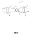
- FIG. 1is a top view of one exemplary embodiment of a vertebral stabilization device of the present invention.
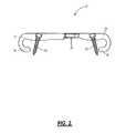
- FIG. 2is side view of the vertebral stabilization device of FIG. 1 .
- FIG. 3is a side view of another exemplary embodiment of a vertebral stabilization device of the present invention.
- FIG. 4is a side view of the vertebral stabilization device of FIGS. 1 and 2 attached to adjacent spinous processes of a spine, the vertebral stabilization device of FIG. 3 being surgically implanted in a similar manner.
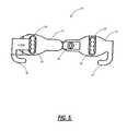
- FIG. 5is a top view of a further exemplary embodiment of a vertebral stabilization device of the present invention.
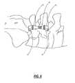
- FIG. 6is a top view of the vertebral stabilization device of FIG. 5 attached to adjacent laminae of a spine,
- FIG. 7is a perspective view of a still further exemplary embodiment of a vertebral stabilization device of the present invention.
- FIG. 8is another perspective view of the vertebral stabilization device of FIG. 7 .
- FIG. 9is a perspective view of a still further exemplary embodiment of a vertebral stabilization device of the present invention.
- FIG. 10is a partial perspective view of the vertebral stabilization device of FIG. 9 .
- FIG. 11is a perspective view of the locking collet of the vertebral stabilization device of FIGS. 9 and 10 .
- FIG. 12is a perspective view of a still further exemplary embodiment of a vertebral stabilization device of the present invention.
- FIG. 13is a partial perspective view of the vertebral stabilization device of FIG. 12 .
- FIG. 14is a perspective view of the connector member of the vertebral stabilization device of FIGS. 12 and 13 .
- FIG. 15is a perspective view of a still further exemplary embodiment of a vertebral stabilization device of the present invention.
- FIG. 16is a partial perspective view of the vertebral stabilization device of FIG. 15 .
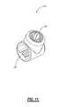
- FIG. 17is a perspective view of the locking collet of the vertebral stabilization device of FIGS. 15 and 16 .
- FIG. 18is a perspective view of a still further exemplary embodiment of a vertebral stabilization device of the present invention.
- FIG. 19is a perspective view of a still further exemplary embodiment of a vertebral stabilization device of the present invention.
- FIG. 1an exemplary vertebral stabilization device is illustrated in FIG. 1 and is shown generally at reference number 10 .
- the vertebral stabilization device 10has a first frame member 12 and a second frame member 14 .
- the first frame member 12 and the second frame member 14are in a telescopic relationship with each other.
- the first frame member 12is partially received within the body of the second frame member 14 for attaching the first frame member 12 to the second frame member 14 and allowing the first frame member 12 and second frame member 14 to collectively expand and contract as a unified whole.
- a first connector member 16is coupled to or integrally formed with the first frame member 12 and a second connector member 18 is coupled to or integrally formed with the second frame member 14 , as illustrated in FIG. 2 .
- the connector members 16 , 18are preferably arcuate in shape for fittingly connecting the vertebral stabilization device 10 to adjacent spinous processes, for example.
- the connector members 16 , 18face arcuately towards each other, as illustrated in FIG. 2 .
- the connector members 16 , 18face acutely opposite each other, as illustrated in FIG. 3 .
- the connector members 16 , 18are configured to fittingly engage either the proximal or distal surfaces of the adjacent spinous processes, for example.
- Each connector member 16 , 18contains mutually overlapping receiving bores 20 ( FIGS. 1 and 3 ) for receiving a bone screw 22 ( FIG. 2 ).
- the bores 20further include a seat 24 ( FIG. 1 ) for engaging the head of the bone screw 22 .
- the bores 20may each include multiple positions for receiving the bone screw 22 (e.g. four positions are illustrated).
- the bores 20define positions for the placement of the screws 22 at multiple locations.
- a securement mechanism 26is positioned on/through the second frame member 14 for selectively and securely engaging the first frame member 12 to the second frame member 14 .
- the first frame member 12is partially received within the body of the second frame member 14 , forming a selectively secured telescopic relationship between the frame members 12 , 14 .
- the securement mechanism 26exerts a stabilizing force on the first frame member 14 .
- the securement mechanism 26is rotated, causing the securement mechanism 26 to move in a downward direction, until it is engaged to the first frame member 12 , thus preventing further movement of the first frame member 12 relative to the second frame member 14 .
- the vertebral stabilization device 10may have any shape and size to perform the intended function and realize the scope of the present invention.
- the height of the vertebral stabilization device 10may range from about 0.5 inches to about 0.75 inches, and the length of the vertebral stabilization device 10 may range from about 2.5 inches to about 2.75 inches, although other suitable dimensions are contemplated, depending upon the specific application.
- FIG. 4illustrates the vertebral stabilization device 10 in use.
- the connector members 16 , 18selectively secure the vertebral stabilization device 10 to adjacent spinous processes, while the bone screws 22 are selectively screwed into the bodies of the adjacent spinous processes. Due to its telescoping nature and the presence of the securement mechanism 26 ( FIGS. 1-3 ), the vertebral stabilization device 10 may be used to stabilize the adjacent spinous processes and, if desired, compress them together, especially in the embodiment of FIGS. 1 and 2 , or distract them apart, especially in the embodiment of FIG. 3 .
- the vertebral stabilization device 10may be coupled to other spinal structures, including, but not limited to, adjacent laminae, a spinous process and a lamina, a spinous process and the sacrum, a lamina and the sacrum, etc. All that needs to be varied in such applications are the relative angles of the connector members 16 , 18 with respect to the rest of the vertebral stabilization device 10 . In other words, the same vertebral stabilization device 10 must simply be configured with respect to size and angles such that the desired structures are fittingly engaged and the bone screws 22 have a substrate with which to mate.
- FIG. 5illustrates a vertebral stabilization device 10 that is configured to engage such adjacent laminae, at the base of adjacent spinous processes
- FIG. 6illustrates this vertebral stabilization device 10 actually engaging such adjacent laminae.
- the relative angles of the connector members 16 , 18are simply varied with respect to the rest of the vertebral stabilization device 10 , the vertebral stabilization device 10 becoming generally more “flat,” in that the connector members 16 , 18 protrude less from the “bottom” and more to the “side” of the vertebral stabilization device 10 , such that the morphology of the adjacent laminae is more accurately addressed.
- FIGS. 7 and 8represent another exemplary embodiment of the vertebral stabilization device 110 of the present invention.
- the vertebral stabilization device 110has a first frame member 112 and a second frame member 114 .
- the first frame member 112 and second frame member 114are in a telescopic relationship with each other, such that proper fit with and, optionally, spinal structure distraction is possible.
- the first frame member 112is received partially within the body of the second frame member 114 for selectively attaching the first frame member 112 to the second frame member 114 and allowing the first frame member 112 and second frame member 114 to collectively expand and contract as a unified whole.
- the exemplary embodimentcontemplates a number of ways to secure the first frame member 112 to the second frame member 114 .
- a rack 120is formed within the body of the first frame member 112 .
- a pawl 122is positioned on the second frame member 114 and engaged to the second frame member 114 by a screw 124 or the like.
- the pawl 122is designed to be inserted between the ridges of the rack 120 , and the screw 124 is selectively tightened to the second frame member 114 , forming a secure arrangement between the first frame member 112 and the second frame member 114 .
- the pawl 122prevents the first frame member 112 from moving when secured, but also allows the appliance 110 to be adjustable when the pawl 122 is unsecured.
- the first frame member 114may be adjusted with respect to the second frame member 112 by way of a pinion 126 in an engaged relationship with the rack 120 .
- the pinion 126is disposed on the side opposite the pawl 122 , allowing the frames 112 , 114 to be adjusted and then secured in a stationary relationship by the pawl 122 .
- the pawl 122is an anti-slip feature that allows the secure locking post distraction or decompression.
- the pinion 126contains a recess 128 designed to receive a tool for selectively rotating or turning the pinion 126 .
- the recessis designed to receive a hexagonal driver (not illustrated).
- the ridges of the pinion 126intersect the ridges of the rack 120 , forcing the rack 120 to translate.
- the rack 120 and pinion 126are designed for self-distraction/compression in-situ without instrumentation.
- a set screw 130is disposed on the top of the vertebral stabilization device 110 for securing the second frame member 114 within the first frame member 112 .
- the set screw 130is positioned within a casing 132 that forms a lip 134 on the first frame member 112 .
- the screw 124is positioned within the casing 132 and is flush or slightly lower than the lip 134 for receiving a tool to rotate the screw 124 .
- the screw 124exerts a force upon the second frame member 114 , securing the first frame member 114 within the second frame member 112 .
- the vertebral stabilization device 110is designed to allow a single instrument to rotate the screw 124 , pinion 126 , and set screw 130 of the vertebral stabilization device 110 in-situ.
- Each frame member 112 , 114includes a first connector member 116 and a second connector member 118 , respectively, as illustrated in FIGS. 7 and 8 .
- the connector members 116 , 118are substantially arcuate in shape.
- the top portion of the connector members 116 , 118contain a bore 136 for receiving a bone screw 138 therethrough.
- the top portion of the connector members 116 , 118contain a threaded bore 136 for receiving a correspondingly threaded bone screw 138 therethrough.
- the bottom portion of the connector members 116 , 118contain a sheath 140 for receiving the tip of the bone screw 138 .
- the sheath 140has a diameter slightly larger than the diameter of the head of the bone screw 138 for securely receiving the bone screw 138 within the sheath 140 .
- the sheath 140protects the tissues from the sharp tip of the bone screw 138 .
- the bore 136may contain a seat (not illustrated) within the bore 136 for positioning the head of the bone screw 138 .
- the first frame member 112 and second frame member 114have a wedge shaped leading edge, nearest the respective connection member 116 , 118 , that supports a less invasive, lateral surgical approach.
- FIG. 9Another exemplary embodiment of the vertebral stabilization device 210 is illustrated in FIG. 9 .
- the first frame member 212is received into the second frame member 214 to form a telescoping relationship.
- the first frame member 212includes a rack 220 , as illustrated in FIG. 10 , with a plurality of ridges disposed on one side of the first frame member 212 .
- the first frame member 212 and second frame member 214are wedge shaped on the distal end, supporting a less invasive, lateral surgical approach.
- a locking collet 222is positioned on the first frame member 212 , as illustrated in FIGS. 9 and 10 .
- the locking collet 222includes a set screw 224 positioned within a casing 226 disposed on the top of the locking collet 222 .
- a rack 228is formed within the inner bore of the locking collet 222 that corresponds with the height, width, and spacing of the rack 220 positioned on the first frame member 212 .
- the rack 228 on the locking collet 222is designed to form an integral relationship with the rack 220 positioned on the second frame member 214 .
- the set screw 224is designed to securely position the locking collet 222 onto the first frame member 212 .
- the first frame member 212 and the second frame member 214in conjunction with the locking collet 222 , permit micromovement in flexion while preventing compression of the spine below a predefined length.
- Each frame member 212 , 214includes a connector member 216 , 218 , as illustrated in FIGS. 9 and 10 .
- the connector members 216 , 218are substantially arcuate in shape.
- the top portion of the connector members 216 , 218contains a bore 230 for receiving a bone screw 232 therethrough.
- the top portion of the connector members 216 , 218contains a threaded bore 230 for receiving a correspondingly threaded bone screw 232 therethrough.
- the bottom portion of the connector members 216 , 218contains a sheath 234 for receiving the tip of the bone screw 232 .
- the sheath 234has a diameter slightly larger than the diameter of the head of the bone screw 232 for securely receiving the bone screw 232 within the sheath.
- the sheath 234is designed to protect the tissues from the sharp tip of the bone screw 232 .
- the bore 230may contain a seat (not illustrated) within the bore 230 for positioning the head of the bone screw 232 .
- This exemplary embodimentalso includes a pair of integral pads 236 .
- An integral pad 236is positioned on the first frame member 212
- an integral pad 236is positioned on the second frame member 214 .
- the pads 236are designed for the attachment of a decompression/distraction instrument to the vertebral distraction device 210 .
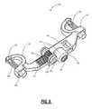
- FIG. 12Another exemplary embodiment of the vertebral stabilization device 310 is illustrated in FIG. 12 .
- the first frame member 312 and second frame member 314each include a ball pivot 318 , as illustrated in FIG. 13 , located on a distal end of each frame member 312 , 314 .
- a ball joint housing 320includes a recess 322 , as illustrated in FIG. 14 , located one the distal end of each frame member 312 , 314 .
- the ball pivot 318 of each frame member 312 , 314is pivotally mounted in the recess 322 of the ball joint housing 320 .
- the ball joint housing 320also includes an integral pad 324 .
- the integral pad 324is positioned on each ball joint housing 320 for the attachment of a decompression/distraction instrument to the vertebral stabilization device 310 .
- Each ball joint housing 320includes a connector member 316 , as illustrated in FIGS. 12 and 13 .
- the top portion of the connector members 316contains a bore 326 for receiving a bone screw 328 therethrough.
- the top portion of the connector members 316contains a threaded bore 326 for receiving a correspondingly threaded bone screw 328 therethrough.
- a distal washer 330may be positioned within a bore 332 located on the bottom portion of the connector members 316 .
- the distal washer 330is designed to receive the tip of the bone screw 328 , and slides laterally within the bore 326 for universal patient matching.
- the bore 326may contain a seat 334 within the bore 326 for positioning the head of the bone screw 328 .
- the first frame member 312includes a rack with a plurality of ridges disposed on one side of the first frame member 312 (not illustrated).
- a locking collet 336is also positioned on the first frame member 312 .
- the locking collet 336includes a set screw 338 positioned within a casing 337 disposed on the top of the locking collet 336 .
- a rackis formed within the inner bore of the locking collet 336 that corresponds with the rack positioned on the second frame member 314 (not illustrated).
- the rack positioned on the locking collet 336is designed to form an integral relationship with the rack positioned on the first frame member 312 .
- the set screw 338is designed to securely position the locking collet 336 onto the first frame member 312 .
- the first frame member 312further includes a pin 340 positioned on an end of the frame member 312 opposite the ball joint housing 320 .
- the pin 340is received within a slot 342 positioned on the second frame member 314 .
- the first frame member 312 and second frame member 314are in a telescoping relationship with each other as defined by the length of the slot.
- the second frame member 314is allowed to translate along the first frame member 312 at a distance as defined by the length of the slot 342 . The movement of the second frame member 314 is prevented when the pin 340 contacts the ends of the slot 342 .
- the distal washer 330provides for universal patient matching and increased stability and strength.
- the distal washer 330allows the vertebral stabilization device 310 to be used on any patient with any thickness of spinous process, lamina, or sacrum.
- the screw lengthmay vary such that the screw's distal end need not project past the washer when fully engaged to the spinous process, thus preventing tissue damage that may be caused by a sharp, self-tapping screw point.
- the first frame member 312 , second member 314 , locking collet 336 , ball pivot 318 , and ball joint housing 320work in conjunction to permit both decompression and dynamic fixation of the spine.
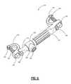
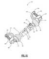
- FIG. 15Another exemplary embodiment of the vertebral stabilization device 410 is illustrated in FIG. 15 .
- the first frame member 412 and second frame member 414each include a ball pivot (not illustrated) located on a distal end.
- a ball joint housing 420 that includes a recess (not illustrated)is also located at the distal end of each frame member 412 , 414 .
- the ball pivot of each frame member 412 , 414is pivotally mounted in a recess of the ball joint housing 420 .
- the ball joint housing 420also includes an integral pad 424 .
- the integral pad 424is positioned on each ball joint housing 420 for attachment of a decompression/distraction instrument.
- Each ball joint housing 420includes a connector member 416 , as illustrated in FIGS. 15 and 16 .
- the connector members 416are substantially arcuate in shape.
- the top portion of the connector members 416contains a bore 426 for receiving a bone screw 428 therethrough.
- the top portion of the connector members 416contains a threaded bore 426 for receiving a correspondingly threaded bone screw 428 therethrough.
- a sheath 444is located on the bottom portion of the connector members 416 for receiving the tip of the bone screw 428 .
- the sheath 444has a diameter that is slightly larger than the diameter of the tip of the bone screw 428 for securely receiving the bone screw 428 within the sheath 444 .
- the sheath 444is designed to protect tissues from the sharp tip of the bone screw 428 .
- the bore 426may contain a seat (not illustrated) within the bore 426 for positioning the head of the bone screw 428 .
- the first frame member 412includes a rack 446 with a plurality of ridges disposed on one side of the first frame member 412 , as illustrated in FIG. 16 .
- a locking collet 434is positioned on the first frame member 412 .
- the locking collet 434includes a set screw 436 positioned within a casing 438 disposed on the top of the locking collet 434 .
- a rack 448is formed within the inner bore of the locking collet 434 that corresponds with the rack 446 positioned on the first frame member 412 , as illustrated in FIG. 17 .
- the rack 448 on the locking collet 434is designed to form an integral relationship with the rack 446 positioned on the first frame member 412 .
- the set screw 436is designed to securely position the locking collet 434 onto the first frame member 412 .
- the first frame member 412further includes a pin 440 positioned on an end opposite the ball joint housing 420 .
- the pin 440is received within a slot 442 positioned on the second frame member 414 .
- the first frame member 412 and second frame member 414are in a telescoping relationship with each other as defined by the length of the slot 442 .
- the second frame member 414is allowed to translate along the first frame member 412 at a distance as defined by the length of the slot 442 .
- the movement of the second frame member 414is prevented when the pin 440 contacts the ends of the slot 442 , thus ceasing further telescoping movement.
- the first frame member 412 , second frame member 414 , locking collet 434 , ball pivot 418 , and ball joint housing 420work in conjunction to permit both decompression and dynamic stabilization of the spine.
- the first frame member 412 and second frame member 414have a wedge shaped design at the distal end to support a less invasive, lateral surgical approach.
- FIG. 18illustrates another exemplary embodiment of the vertebral stabilization device 510 .
- the vertebral stabilization device 510has a first frame member 512 and a second frame member 514 .
- the first frame member 512 and second frame member 514are in a telescopic relationship with each other.
- the first frame member 512is partially received within the second frame member 514 for attaching the first frame member 512 to the second frame member 514 and allowing the first frame member 512 and second frame member 514 to collectively expand and contract.
- the second frame member 514contains an upright 518 on the distal end.
- the upright 518contains a horizontal bore 520 and a vertical bore 522 .
- the horizontal bore 520is designed to receive the first frame member 512 .
- the vertical bore 522is threaded to receive a correspondingly threaded set screw 524 .
- the set screw 524contains a recess for receiving a tool to rotate the set screw 524 within the vertical bore 522 . As the set screw 524 is rotated, the base of the set screw 524 secures the first frame member 512 within the horizontal bore 520 .
- Each frame member 512 , 514includes a connector member 516 , as illustrated in FIG. 18 .
- the connector members 516are substantially arcuate in shape.
- the top portion of the connector members 516contains a bore 526 for receiving a bone screw 528 therethrough.
- the top portion of the connector member 516contains a bore 526 for receiving a correspondingly threaded bone screw 528 therethrough.
- the bore 526may contain a seat (not illustrated) within the bore 526 for positioning the head of the bone screw 528 .
- a distal washer 532may be positioned within a bore 534 located on the bottom portion of the connector member 516 .
- the distal washer 532is designed to receive the tip of the bone screw 528 , and slides laterally within the bore 534 for universal patient matching.
- the distal washer 532is retained with the bore 526 by a snap ring 536 that allows the distal washer 532 to slide laterally, but not separate from the connector member 516 .
- the distal washer 532provides for universal patient matching and increased stability and strength.
- the distal washer 532allows the vertebral stabilization device 510 to be used on any patient with any thickness of spinous process, lamina, or sacrum.
- the screw lengthmay vary such that the screw's distal end need not project past the washer when fully engaged to the spinous process, thus preventing tissue damage that may be caused by a sharp, self-tapping screw point.
- FIG. 19illustrates another exemplary embodiment of the vertebral stabilization device 610 .
- the vertebral stabilization device 610has a first frame member 612 and a second frame member 614 .
- the first frame member 612 and second frame member 614are in a telescopic relationship with each other.
- the first frame member 612is partially received within the second frame member 614 for attaching the first frame member 612 to the second frame member 614 and allowing the first frame member 612 and second frame member 614 to collectively expand and contract.
- the second frame member 614contains an upright 618 on the distal end.
- the upright 618contains a horizontal bore 620 and a vertical bore 622 .
- the horizontal bore 620is designed to receive the first frame member 612 .
- the vertical bore 622is threaded to receive a correspondingly threaded set screw 624 .
- the set screw 624contains a recess for receiving a tool to rotate the set screw 624 within the vertical bore 622 . As the set screw 624 is rotated, the base of the set screw 624 secures the first frame member 612 within the horizontal bore 620 .
- the set screw 624locks the first frame member 612 during post distraction or compression.
- Each frame member 612 , 614includes an connector member 616 , as illustrated in FIG. 19 .
- the connector members 616are substantially arcuate in shape.
- the top portion of the connector members 616contains a bore 626 for receiving a bone screw 628 .
- the top portion of the connector members 616contains a bore 626 for receiving a correspondingly threaded bone screw 628 therethrough.
- the bore 626may contain a seat (not illustrated) within the bore 626 for positioning the head of the bone screw 628 .
- the bottom portion of the connector members 616contains a threaded bore 632 for receiving the correspondingly threaded bone screw 628 .
- the connector members 616may be rotated 180 degrees for distraction of the spine.
- the bores 626 , 632 positioned within the connector member 616aid in the predictable placement of the bone screw 628 by acting as a guide.
- the screw lengthmay vary such that the screw's distal end need not project past the connector member 616 when fully engaged to the spinous processes, lamina, or sacrum, thus preventing tissue damage that may be caused by a sharp, self-tapping screw point.
- the vertebral stabilization devices of the present inventionmay be formed of a variety of materials.
- the surfacesmay be formed from biocompatible metals, such as cobalt chromium, chromium steel, surgical steel, titanium, titanium alloys, tantalum, tantalum alloys, aluminum, or the like.
- Suitable ceramics or other suitable biocompatible materials known in the artmay also be utilized.
- Suitable polymersinclude polyesters, aromatic esters, such as polyalkylene terephthalates, polyamides, polyalkenes, poly(vinyl)fluoride, PTFE, polyarylethyl ketone, and the like.
Landscapes
- Health & Medical Sciences (AREA)
- Orthopedic Medicine & Surgery (AREA)
- Life Sciences & Earth Sciences (AREA)
- Neurology (AREA)
- Surgery (AREA)
- Heart & Thoracic Surgery (AREA)
- Engineering & Computer Science (AREA)
- Biomedical Technology (AREA)
- Nuclear Medicine, Radiotherapy & Molecular Imaging (AREA)
- Medical Informatics (AREA)
- Molecular Biology (AREA)
- Animal Behavior & Ethology (AREA)
- General Health & Medical Sciences (AREA)
- Public Health (AREA)
- Veterinary Medicine (AREA)
- Surgical Instruments (AREA)
- Prostheses (AREA)
Abstract
Description
Claims (12)
Priority Applications (1)
| Application Number | Priority Date | Filing Date | Title |
|---|---|---|---|
| US12/051,202US8828061B2 (en) | 2007-03-19 | 2008-03-19 | Vertebral stabilization devices and associated surgical methods |
Applications Claiming Priority (2)
| Application Number | Priority Date | Filing Date | Title |
|---|---|---|---|
| US89555107P | 2007-03-19 | 2007-03-19 | |
| US12/051,202US8828061B2 (en) | 2007-03-19 | 2008-03-19 | Vertebral stabilization devices and associated surgical methods |
Publications (2)
| Publication Number | Publication Date |
|---|---|
| US20080234733A1 US20080234733A1 (en) | 2008-09-25 |
| US8828061B2true US8828061B2 (en) | 2014-09-09 |
Family
ID=39775508
Family Applications (1)
| Application Number | Title | Priority Date | Filing Date |
|---|---|---|---|
| US12/051,202Active2029-08-03US8828061B2 (en) | 2007-03-19 | 2008-03-19 | Vertebral stabilization devices and associated surgical methods |
Country Status (1)
| Country | Link |
|---|---|
| US (1) | US8828061B2 (en) |
Cited By (13)
| Publication number | Priority date | Publication date | Assignee | Title |
|---|---|---|---|---|
| US20140128917A1 (en)* | 2007-01-29 | 2014-05-08 | Samy Abdou | Inter-vertebral orthopedic device placement |
| US9763703B2 (en) | 2015-05-05 | 2017-09-19 | Degen Medical, Inc. | Cross connectors, kits, and methods |
| US10543107B2 (en) | 2009-12-07 | 2020-01-28 | Samy Abdou | Devices and methods for minimally invasive spinal stabilization and instrumentation |
| US10548740B1 (en) | 2016-10-25 | 2020-02-04 | Samy Abdou | Devices and methods for vertebral bone realignment |
| US10575961B1 (en) | 2011-09-23 | 2020-03-03 | Samy Abdou | Spinal fixation devices and methods of use |
| US10695105B2 (en) | 2012-08-28 | 2020-06-30 | Samy Abdou | Spinal fixation devices and methods of use |
| US10857003B1 (en) | 2015-10-14 | 2020-12-08 | Samy Abdou | Devices and methods for vertebral stabilization |
| US10918498B2 (en) | 2004-11-24 | 2021-02-16 | Samy Abdou | Devices and methods for inter-vertebral orthopedic device placement |
| US10973648B1 (en) | 2016-10-25 | 2021-04-13 | Samy Abdou | Devices and methods for vertebral bone realignment |
| US11006982B2 (en) | 2012-02-22 | 2021-05-18 | Samy Abdou | Spinous process fixation devices and methods of use |
| US11173040B2 (en) | 2012-10-22 | 2021-11-16 | Cogent Spine, LLC | Devices and methods for spinal stabilization and instrumentation |
| US11179248B2 (en) | 2018-10-02 | 2021-11-23 | Samy Abdou | Devices and methods for spinal implantation |
| US20230085446A1 (en)* | 2007-06-22 | 2023-03-16 | Empirical Spine, Inc, | Methods and systems for increasing the bending stiffness of a spinal segment with elongation limit |
Families Citing this family (54)
| Publication number | Priority date | Publication date | Assignee | Title |
|---|---|---|---|---|
| US9055981B2 (en) | 2004-10-25 | 2015-06-16 | Lanx, Inc. | Spinal implants and methods |
| US8241330B2 (en) | 2007-01-11 | 2012-08-14 | Lanx, Inc. | Spinous process implants and associated methods |
| WO2008070863A2 (en) | 2006-12-07 | 2008-06-12 | Interventional Spine, Inc. | Intervertebral implant |
| US8231660B2 (en)* | 2007-07-18 | 2012-07-31 | Spinefrontier Inc | System and method for facet fixation |
| US9265532B2 (en) | 2007-01-11 | 2016-02-23 | Lanx, Inc. | Interspinous implants and methods |
| US9247968B2 (en) | 2007-01-11 | 2016-02-02 | Lanx, Inc. | Spinous process implants and associated methods |
| US8900307B2 (en) | 2007-06-26 | 2014-12-02 | DePuy Synthes Products, LLC | Highly lordosed fusion cage |
| US8790380B2 (en)* | 2007-07-26 | 2014-07-29 | Dynamic Spine, Llc | Segmental orthopaedic device for spinal elongation and for treatment of scoliosis |
| US9204908B2 (en)* | 2007-07-26 | 2015-12-08 | Dynamic Spine, Llc | Segmental orthopedic device for spinal elongation and for treatment of scoliosis |
| US8048129B2 (en)* | 2007-08-15 | 2011-11-01 | Zimmer Spine, Inc. | MIS crosslink apparatus and methods for spinal implant |
| EP2237748B1 (en) | 2008-01-17 | 2012-09-05 | Synthes GmbH | An expandable intervertebral implant |
| US8936641B2 (en) | 2008-04-05 | 2015-01-20 | DePuy Synthes Products, LLC | Expandable intervertebral implant |
| FR2930718B1 (en)* | 2008-05-02 | 2010-05-14 | Warsaw Orthopedic Inc | BONDING ELEMENT OF A VERTEBRAL OSTEOSYNTHESIS DEVICE, AND A VERTEBRAL OSTEOSYNTHESIS DEVICE COMPRISING SAME |
| US20100121381A1 (en)* | 2008-06-09 | 2010-05-13 | Springback, Inc. | Surgical method and apparatus for treating spinal stenosis and stabilization of vertebrae |
| US20110137345A1 (en)* | 2009-03-18 | 2011-06-09 | Caleb Stoll | Posterior lumbar fusion |
| US9526620B2 (en) | 2009-03-30 | 2016-12-27 | DePuy Synthes Products, Inc. | Zero profile spinal fusion cage |
| US9028553B2 (en) | 2009-11-05 | 2015-05-12 | DePuy Synthes Products, Inc. | Self-pivoting spinal implant and associated instrumentation |
| US9393129B2 (en) | 2009-12-10 | 2016-07-19 | DePuy Synthes Products, Inc. | Bellows-like expandable interbody fusion cage |
| AU2011264818B2 (en) | 2010-06-10 | 2015-06-18 | Globus Medical, Inc. | Low-profile, uniplanar bone screw |
| US9907560B2 (en) | 2010-06-24 | 2018-03-06 | DePuy Synthes Products, Inc. | Flexible vertebral body shavers |
| US8979860B2 (en) | 2010-06-24 | 2015-03-17 | DePuy Synthes Products. LLC | Enhanced cage insertion device |
| US8623091B2 (en) | 2010-06-29 | 2014-01-07 | DePuy Synthes Products, LLC | Distractible intervertebral implant |
| US9402732B2 (en) | 2010-10-11 | 2016-08-02 | DePuy Synthes Products, Inc. | Expandable interspinous process spacer implant |
| JP6076912B2 (en)* | 2010-11-30 | 2017-02-08 | デピュイ・シンセス・プロダクツ・インコーポレイテッド | Lateral spondylolisthesis reduction cage |
| EP3485851B1 (en) | 2011-03-22 | 2021-08-25 | DePuy Synthes Products, LLC | Universal trial for lateral cages |
| US11812923B2 (en) | 2011-10-07 | 2023-11-14 | Alan Villavicencio | Spinal fixation device |
| US9226764B2 (en) | 2012-03-06 | 2016-01-05 | DePuy Synthes Products, Inc. | Conformable soft tissue removal instruments |
| US9138325B2 (en)* | 2012-07-11 | 2015-09-22 | Globus Medical, Inc. | Lamina implant and method |
| US10660674B2 (en)* | 2012-07-17 | 2020-05-26 | Gomboc, LLC | Magnetically levitated spinous process implants and methods thereof |
| US10022245B2 (en) | 2012-12-17 | 2018-07-17 | DePuy Synthes Products, Inc. | Polyaxial articulating instrument |
| CN103126756B (en)* | 2013-02-04 | 2015-04-15 | 中国人民解放军第二军医大学 | Posterior pelvic ring fracture minimally-invasive fixator |
| US9717601B2 (en) | 2013-02-28 | 2017-08-01 | DePuy Synthes Products, Inc. | Expandable intervertebral implant, system, kit and method |
| US9522070B2 (en) | 2013-03-07 | 2016-12-20 | Interventional Spine, Inc. | Intervertebral implant |
| US9510872B2 (en)* | 2013-03-15 | 2016-12-06 | Jcbd, Llc | Spinal stabilization system |
| EP3131486B1 (en)* | 2014-04-16 | 2023-06-14 | Dynamic Spine, LLC | Adjustable screw-clamp orthopedic apparatus |
| US11426290B2 (en) | 2015-03-06 | 2022-08-30 | DePuy Synthes Products, Inc. | Expandable intervertebral implant, system, kit and method |
| US9962192B2 (en) | 2016-03-17 | 2018-05-08 | Medos International Sarl | Multipoint fixation implants |
| US11510788B2 (en) | 2016-06-28 | 2022-11-29 | Eit Emerging Implant Technologies Gmbh | Expandable, angularly adjustable intervertebral cages |
| EP3474784A2 (en) | 2016-06-28 | 2019-05-01 | Eit Emerging Implant Technologies GmbH | Expandable and angularly adjustable intervertebral cages with articulating joint |
| US10398563B2 (en) | 2017-05-08 | 2019-09-03 | Medos International Sarl | Expandable cage |
| US11344424B2 (en) | 2017-06-14 | 2022-05-31 | Medos International Sarl | Expandable intervertebral implant and related methods |
| US10966843B2 (en) | 2017-07-18 | 2021-04-06 | DePuy Synthes Products, Inc. | Implant inserters and related methods |
| US11045331B2 (en) | 2017-08-14 | 2021-06-29 | DePuy Synthes Products, Inc. | Intervertebral implant inserters and related methods |
| US10898232B2 (en) | 2018-03-20 | 2021-01-26 | Medos International Sàrl | Multipoint fixation implants and related methods |
| US11678995B2 (en) | 2018-07-20 | 2023-06-20 | Fellowship Of Orthopaedic Researchers, Inc. | Magnetic intervertebral disc replacement devices and methods thereof |
| US11446156B2 (en) | 2018-10-25 | 2022-09-20 | Medos International Sarl | Expandable intervertebral implant, inserter instrument, and related methods |
| US11426210B2 (en) | 2019-09-25 | 2022-08-30 | Medos International Sàrl | Multipoint angled fixation implants for multiple screws and related methods |
| EP4103083B1 (en) | 2020-02-14 | 2024-10-23 | Medos International Sàrl | Integrated multipoint fixation screw |
| US11426286B2 (en) | 2020-03-06 | 2022-08-30 | Eit Emerging Implant Technologies Gmbh | Expandable intervertebral implant |
| US11627997B1 (en)* | 2020-10-01 | 2023-04-18 | Jason Zook | Lumbar spinous process static and dynamic stabilization device |
| US11850160B2 (en) | 2021-03-26 | 2023-12-26 | Medos International Sarl | Expandable lordotic intervertebral fusion cage |
| US11752009B2 (en) | 2021-04-06 | 2023-09-12 | Medos International Sarl | Expandable intervertebral fusion cage |
| US12090064B2 (en) | 2022-03-01 | 2024-09-17 | Medos International Sarl | Stabilization members for expandable intervertebral implants, and related systems and methods |
| WO2025085634A1 (en)* | 2023-10-17 | 2025-04-24 | Mb Innovations, Inc. | Implants, systems and methods for installing implants |
Citations (8)
| Publication number | Priority date | Publication date | Assignee | Title |
|---|---|---|---|---|
| US6083226A (en)* | 1998-04-22 | 2000-07-04 | Fiz; Daniel | Bone fixation device and transverse linking bridge |
| US6113600A (en)* | 1995-06-06 | 2000-09-05 | Denek Medical, Inc. | Device for linking adjacent rods in spinal instrumentation |
| US20020029039A1 (en)* | 1997-01-02 | 2002-03-07 | Zucherman James F. | Supplemental spine fixation device and methods |
| US20020183749A1 (en)* | 2000-01-24 | 2002-12-05 | Burgess Ian C. | Transverse connector |
| US20030153914A1 (en)* | 2002-02-08 | 2003-08-14 | Showa Ika Kohgyo Co., Ltd. | Rod distance retainer |
| US20040092931A1 (en)* | 2000-11-07 | 2004-05-13 | Jean Taylor | Vertebral arthrodesis equipment |
| US20040127906A1 (en)* | 2002-07-19 | 2004-07-01 | Culbert Brad S. | Method and apparatus for spinal fixation |
| US20080109039A1 (en)* | 2006-11-08 | 2008-05-08 | Depuy Spine, Inc. | Spinal cross connectors |
- 2008
- 2008-03-19USUS12/051,202patent/US8828061B2/enactiveActive
Patent Citations (9)
| Publication number | Priority date | Publication date | Assignee | Title |
|---|---|---|---|---|
| US6113600A (en)* | 1995-06-06 | 2000-09-05 | Denek Medical, Inc. | Device for linking adjacent rods in spinal instrumentation |
| US20020029039A1 (en)* | 1997-01-02 | 2002-03-07 | Zucherman James F. | Supplemental spine fixation device and methods |
| US20050240182A1 (en)* | 1997-01-02 | 2005-10-27 | St. Francis Medical Technologies, Inc. | Supplemental spine fixation device and method |
| US6083226A (en)* | 1998-04-22 | 2000-07-04 | Fiz; Daniel | Bone fixation device and transverse linking bridge |
| US20020183749A1 (en)* | 2000-01-24 | 2002-12-05 | Burgess Ian C. | Transverse connector |
| US20040092931A1 (en)* | 2000-11-07 | 2004-05-13 | Jean Taylor | Vertebral arthrodesis equipment |
| US20030153914A1 (en)* | 2002-02-08 | 2003-08-14 | Showa Ika Kohgyo Co., Ltd. | Rod distance retainer |
| US20040127906A1 (en)* | 2002-07-19 | 2004-07-01 | Culbert Brad S. | Method and apparatus for spinal fixation |
| US20080109039A1 (en)* | 2006-11-08 | 2008-05-08 | Depuy Spine, Inc. | Spinal cross connectors |
Cited By (30)
| Publication number | Priority date | Publication date | Assignee | Title |
|---|---|---|---|---|
| US11096799B2 (en) | 2004-11-24 | 2021-08-24 | Samy Abdou | Devices and methods for inter-vertebral orthopedic device placement |
| US10918498B2 (en) | 2004-11-24 | 2021-02-16 | Samy Abdou | Devices and methods for inter-vertebral orthopedic device placement |
| US11992423B2 (en) | 2004-11-24 | 2024-05-28 | Samy Abdou | Devices and methods for inter-vertebral orthopedic device placement |
| US20140128917A1 (en)* | 2007-01-29 | 2014-05-08 | Samy Abdou | Inter-vertebral orthopedic device placement |
| US20230085446A1 (en)* | 2007-06-22 | 2023-03-16 | Empirical Spine, Inc, | Methods and systems for increasing the bending stiffness of a spinal segment with elongation limit |
| US10857004B2 (en) | 2009-12-07 | 2020-12-08 | Samy Abdou | Devices and methods for minimally invasive spinal stabilization and instrumentation |
| US10543107B2 (en) | 2009-12-07 | 2020-01-28 | Samy Abdou | Devices and methods for minimally invasive spinal stabilization and instrumentation |
| US11918486B2 (en) | 2009-12-07 | 2024-03-05 | Samy Abdou | Devices and methods for minimally invasive spinal stabilization and instrumentation |
| US10610380B2 (en) | 2009-12-07 | 2020-04-07 | Samy Abdou | Devices and methods for minimally invasive spinal stabilization and instrumentation |
| US10945861B2 (en) | 2009-12-07 | 2021-03-16 | Samy Abdou | Devices and methods for minimally invasive spinal stabilization and instrumentation |
| US10575961B1 (en) | 2011-09-23 | 2020-03-03 | Samy Abdou | Spinal fixation devices and methods of use |
| US11324608B2 (en) | 2011-09-23 | 2022-05-10 | Samy Abdou | Spinal fixation devices and methods of use |
| US11517449B2 (en) | 2011-09-23 | 2022-12-06 | Samy Abdou | Spinal fixation devices and methods of use |
| US12167973B2 (en) | 2011-09-23 | 2024-12-17 | Samy Abdou | Spinal fixation devices and methods of use |
| US11006982B2 (en) | 2012-02-22 | 2021-05-18 | Samy Abdou | Spinous process fixation devices and methods of use |
| US11839413B2 (en) | 2012-02-22 | 2023-12-12 | Samy Abdou | Spinous process fixation devices and methods of use |
| US10695105B2 (en) | 2012-08-28 | 2020-06-30 | Samy Abdou | Spinal fixation devices and methods of use |
| US11559336B2 (en) | 2012-08-28 | 2023-01-24 | Samy Abdou | Spinal fixation devices and methods of use |
| US11173040B2 (en) | 2012-10-22 | 2021-11-16 | Cogent Spine, LLC | Devices and methods for spinal stabilization and instrumentation |
| US11918483B2 (en) | 2012-10-22 | 2024-03-05 | Cogent Spine Llc | Devices and methods for spinal stabilization and instrumentation |
| US9763703B2 (en) | 2015-05-05 | 2017-09-19 | Degen Medical, Inc. | Cross connectors, kits, and methods |
| US11246718B2 (en) | 2015-10-14 | 2022-02-15 | Samy Abdou | Devices and methods for vertebral stabilization |
| US10857003B1 (en) | 2015-10-14 | 2020-12-08 | Samy Abdou | Devices and methods for vertebral stabilization |
| US10744000B1 (en) | 2016-10-25 | 2020-08-18 | Samy Abdou | Devices and methods for vertebral bone realignment |
| US11752008B1 (en) | 2016-10-25 | 2023-09-12 | Samy Abdou | Devices and methods for vertebral bone realignment |
| US11259935B1 (en) | 2016-10-25 | 2022-03-01 | Samy Abdou | Devices and methods for vertebral bone realignment |
| US11058548B1 (en) | 2016-10-25 | 2021-07-13 | Samy Abdou | Devices and methods for vertebral bone realignment |
| US10973648B1 (en) | 2016-10-25 | 2021-04-13 | Samy Abdou | Devices and methods for vertebral bone realignment |
| US10548740B1 (en) | 2016-10-25 | 2020-02-04 | Samy Abdou | Devices and methods for vertebral bone realignment |
| US11179248B2 (en) | 2018-10-02 | 2021-11-23 | Samy Abdou | Devices and methods for spinal implantation |
Also Published As
| Publication number | Publication date |
|---|---|
| US20080234733A1 (en) | 2008-09-25 |
Similar Documents
| Publication | Publication Date | Title |
|---|---|---|
| US8828061B2 (en) | Vertebral stabilization devices and associated surgical methods | |
| USRE49410E1 (en) | Rod reducer, compressor, distractor system | |
| US7918875B2 (en) | Interspinous distraction devices and associated methods of insertion | |
| US8007517B2 (en) | Interspinous distraction devices and associated methods of insertion | |
| US12262918B2 (en) | Orthopedic fixation devices and methods of installation thereof | |
| US12262923B2 (en) | Polyaxial bone screw with increased angulation | |
| US7473268B2 (en) | Mating insertion instruments for spinal implants and methods of use | |
| US8915945B2 (en) | Adjustable multi-axial spinal coupling assemblies | |
| US8025678B2 (en) | Interspinous process spacer having tight access offset hooks | |
| US8313512B2 (en) | S-shaped interspinous process spacer having tight access offset hooks | |
| US6902566B2 (en) | Spinal implants, insertion instruments, and methods of use | |
| AU2014259592B2 (en) | System for corrective spinal surgery and method of use | |
| US8007518B2 (en) | Load-sharing component having a deflectable post and method for dynamic stabilization of the spine | |
| US9480502B2 (en) | Expansion interspinous fixation device and method | |
| US9844398B2 (en) | Surgical connectors and instrumentation | |
| CN104220017B (en) | Telescoping interspinous fixation device and methods of use | |
| US10993746B2 (en) | Head to head transverse connector | |
| US8083772B2 (en) | Dynamic spinal rod assembly and method for dynamic stabilization of the spine | |
| US8021396B2 (en) | Configurable dynamic spinal rod and method for dynamic stabilization of the spine | |
| US20070225712A1 (en) | Systems and methods for posterior dynamic stabilization of the spine | |
| US8092501B2 (en) | Dynamic spinal rod and method for dynamic stabilization of the spine | |
| US9763706B2 (en) | Interspinous fusion device | |
| US20100036437A1 (en) | Load-sharing bone anchor having a deflectable post with a compliant ring and method for stabilization of the spine | |
| US20120245638A1 (en) | Sacral brace | |
| US20250169808A1 (en) | Tlif distraction and retraction |
Legal Events
| Date | Code | Title | Description |
|---|---|---|---|
| AS | Assignment | Owner name:U.S. SPINAL TECHNOLOGIES, L.L.C., FLORIDA Free format text:ASSIGNMENT OF ASSIGNORS INTEREST;ASSIGNORS:SCRANTZ, KELLY;LANDRENEAU, FRASER;MITCHELL, HORACE;AND OTHERS;REEL/FRAME:021030/0058;SIGNING DATES FROM 20080319 TO 20080522 Owner name:U.S. SPINAL TECHNOLOGIES, L.L.C., FLORIDA Free format text:ASSIGNMENT OF ASSIGNORS INTEREST;ASSIGNORS:SCRANTZ, KELLY;LANDRENEAU, FRASER;MITCHELL, HORACE;AND OTHERS;SIGNING DATES FROM 20080319 TO 20080522;REEL/FRAME:021030/0058 | |
| AS | Assignment | Owner name:US SPINE, INC., UTAH Free format text:CHANGE OF NAME;ASSIGNOR:U.S. SPINAL TECHNOLOGIES, LLC;REEL/FRAME:025420/0972 Effective date:20101123 | |
| AS | Assignment | Owner name:ZIONS FIRST NATIONAL BANK, UTAH Free format text:SECURITY AGREEMENT;ASSIGNOR:US SPINE, INC.;REEL/FRAME:025434/0317 Effective date:20100917 | |
| AS | Assignment | Owner name:KARL KIPKE, AS COLLATERAL AGENT, TEXAS Free format text:SECURITY AGREEMENT;ASSIGNOR:AMEDICA CORPORATION;REEL/FRAME:025900/0168 Effective date:20110303 | |
| AS | Assignment | Owner name:US SPINE, INC., UTAH Free format text:RELEASE BY SECURED PARTY;ASSIGNOR:ZIONS FIRST NATIONAL BANK;REEL/FRAME:029491/0085 Effective date:20121217 Owner name:AMEDICA CORPORATION, UTAH Free format text:RELEASE BY SECURED PARTY;ASSIGNOR:AS COLLATERAL AGENT, KARL KIPKE;REEL/FRAME:029492/0321 Effective date:20121214 Owner name:GE CAPITAL EQUITY INVESTMENTS, INC. C/O GE HEALTHC Free format text:SECURITY AGREEMENT;ASSIGNORS:AMEDICA CORPORATION;US SPINE, INC.;REEL/FRAME:029495/0211 Effective date:20121214 | |
| AS | Assignment | Owner name:GENERAL ELECTRIC CAPITAL CORPORATION, MARYLAND Free format text:CORRECTIVE ASSIGNMENT TO CORRECT THE NAME OF THE ASSIGNEE PREVIOUSLY RECORDED ON REEL 029495 FRAME 0211. ASSIGNOR(S) HEREBY CONFIRMS THE ASSIGNOR: AMEDICA CORPORATION ASSIGNOR: US SPINE, INC. ASSIGNEE: GENERAL ELECTRIC CAPITAL CORPORATION;ASSIGNORS:AMEDICA CORPORATION;US SPINE, INC.;REEL/FRAME:031581/0831 Effective date:20121214 | |
| STCF | Information on status: patent grant | Free format text:PATENTED CASE | |
| AS | Assignment | Owner name:AMEDICA CORPORATION, UTAH Free format text:ASSIGNMENT OF ASSIGNORS INTEREST;ASSIGNOR:U.S. SPINE, INC.;REEL/FRAME:044795/0780 Effective date:20180127 | |
| MAFP | Maintenance fee payment | Free format text:PAYMENT OF MAINTENANCE FEE, 4TH YR, SMALL ENTITY (ORIGINAL EVENT CODE: M2551) Year of fee payment:4 | |
| AS | Assignment | Owner name:US SPINE, INC., UTAH Free format text:RELEASE BY SECURED PARTY;ASSIGNOR:GENERAL ELECTRIC CAPITAL CORPORATION;REEL/FRAME:047199/0313 Effective date:20140630 Owner name:AMEDICA CORPORATION, UTAH Free format text:RELEASE BY SECURED PARTY;ASSIGNOR:GENERAL ELECTRIC CAPITAL CORPORATION;REEL/FRAME:047199/0313 Effective date:20140630 | |
| AS | Assignment | Owner name:AMEDICA CORPORATION, UTAH Free format text:CORRECTIVE ASSIGNMENT TO CORRECT THE PATENT NUMBER PREVIOUSLY RECORDED AT REEL: 047199 FRAME: 0313. ASSIGNOR(S) HEREBY CONFIRMS THE RELEASE OF SECURITY INTEREST;ASSIGNOR:GENERAL ELECTRIC CAPITAL CORPORATION;REEL/FRAME:047403/0953 Effective date:20140630 Owner name:US SPINE, INC., UTAH Free format text:CORRECTIVE ASSIGNMENT TO CORRECT THE PATENT NUMBER PREVIOUSLY RECORDED AT REEL: 047199 FRAME: 0313. ASSIGNOR(S) HEREBY CONFIRMS THE RELEASE OF SECURITY INTEREST;ASSIGNOR:GENERAL ELECTRIC CAPITAL CORPORATION;REEL/FRAME:047403/0953 Effective date:20140630 | |
| AS | Assignment | Owner name:CTL MEDICAL CORPORATION, TEXAS Free format text:ASSIGNMENT OF ASSIGNORS INTEREST;ASSIGNORS:AMEDICA CORPORATION;U.S. SPINE, INC.;REEL/FRAME:051368/0261 Effective date:20181001 | |
| AS | Assignment | Owner name:SOURCE CAPITAL CREDIT OPPORTUNITIES FUND III, LP, GEORGIA Free format text:SECURITY INTEREST;ASSIGNOR:CTL MEDICAL CORPORATION;REEL/FRAME:056417/0573 Effective date:20210513 | |
| AS | Assignment | Owner name:STERLING NATIONAL BANK, NEW YORK Free format text:SECURITY AGREEMENT;ASSIGNOR:CTL MEDICAL CORPORATION;REEL/FRAME:056595/0562 Effective date:20210513 | |
| MAFP | Maintenance fee payment | Free format text:PAYMENT OF MAINTENANCE FEE, 8TH YR, SMALL ENTITY (ORIGINAL EVENT CODE: M2552); ENTITY STATUS OF PATENT OWNER: SMALL ENTITY Year of fee payment:8 |