US8828058B2 - Growth directed vertebral fixation system with distractible connector(s) and apical control - Google Patents
Growth directed vertebral fixation system with distractible connector(s) and apical controlDownload PDFInfo
- Publication number
- US8828058B2 US8828058B2US12/873,582US87358210AUS8828058B2US 8828058 B2US8828058 B2US 8828058B2US 87358210 AUS87358210 AUS 87358210AUS 8828058 B2US8828058 B2US 8828058B2
- Authority
- US
- United States
- Prior art keywords
- rod
- connector
- spine
- vertebra
- correction
- Prior art date
- Legal status (The legal status is an assumption and is not a legal conclusion. Google has not performed a legal analysis and makes no representation as to the accuracy of the status listed.)
- Active
Links
Images


Classifications
- A—HUMAN NECESSITIES
- A61—MEDICAL OR VETERINARY SCIENCE; HYGIENE
- A61B—DIAGNOSIS; SURGERY; IDENTIFICATION
- A61B17/00—Surgical instruments, devices or methods
- A61B17/56—Surgical instruments or methods for treatment of bones or joints; Devices specially adapted therefor
- A61B17/58—Surgical instruments or methods for treatment of bones or joints; Devices specially adapted therefor for osteosynthesis, e.g. bone plates, screws or setting implements
- A61B17/68—Internal fixation devices, including fasteners and spinal fixators, even if a part thereof projects from the skin
- A61B17/70—Spinal positioners or stabilisers, e.g. stabilisers comprising fluid filler in an implant
- A61B17/7049—Connectors, not bearing on the vertebrae, for linking longitudinal elements together
- A61B17/705—Connectors, not bearing on the vertebrae, for linking longitudinal elements together for linking adjacent ends of longitudinal elements
- A—HUMAN NECESSITIES
- A61—MEDICAL OR VETERINARY SCIENCE; HYGIENE
- A61B—DIAGNOSIS; SURGERY; IDENTIFICATION
- A61B17/00—Surgical instruments, devices or methods
- A61B17/56—Surgical instruments or methods for treatment of bones or joints; Devices specially adapted therefor
- A61B17/58—Surgical instruments or methods for treatment of bones or joints; Devices specially adapted therefor for osteosynthesis, e.g. bone plates, screws or setting implements
- A61B17/68—Internal fixation devices, including fasteners and spinal fixators, even if a part thereof projects from the skin
- A61B17/70—Spinal positioners or stabilisers, e.g. stabilisers comprising fluid filler in an implant
- A61B17/7001—Screws or hooks combined with longitudinal elements which do not contact vertebrae
- A61B17/7002—Longitudinal elements, e.g. rods
- A61B17/701—Longitudinal elements with a non-circular, e.g. rectangular, cross-section
- A—HUMAN NECESSITIES
- A61—MEDICAL OR VETERINARY SCIENCE; HYGIENE
- A61B—DIAGNOSIS; SURGERY; IDENTIFICATION
- A61B17/00—Surgical instruments, devices or methods
- A61B17/56—Surgical instruments or methods for treatment of bones or joints; Devices specially adapted therefor
- A61B17/58—Surgical instruments or methods for treatment of bones or joints; Devices specially adapted therefor for osteosynthesis, e.g. bone plates, screws or setting implements
- A61B17/68—Internal fixation devices, including fasteners and spinal fixators, even if a part thereof projects from the skin
- A61B17/70—Spinal positioners or stabilisers, e.g. stabilisers comprising fluid filler in an implant
- A61B17/7001—Screws or hooks combined with longitudinal elements which do not contact vertebrae
- A61B17/7002—Longitudinal elements, e.g. rods
- A61B17/7014—Longitudinal elements, e.g. rods with means for adjusting the distance between two screws or hooks
- A—HUMAN NECESSITIES
- A61—MEDICAL OR VETERINARY SCIENCE; HYGIENE
- A61B—DIAGNOSIS; SURGERY; IDENTIFICATION
- A61B17/00—Surgical instruments, devices or methods
- A61B17/56—Surgical instruments or methods for treatment of bones or joints; Devices specially adapted therefor
- A61B17/58—Surgical instruments or methods for treatment of bones or joints; Devices specially adapted therefor for osteosynthesis, e.g. bone plates, screws or setting implements
- A61B17/68—Internal fixation devices, including fasteners and spinal fixators, even if a part thereof projects from the skin
- A61B17/70—Spinal positioners or stabilisers, e.g. stabilisers comprising fluid filler in an implant
- A61B17/7001—Screws or hooks combined with longitudinal elements which do not contact vertebrae
- A61B17/7002—Longitudinal elements, e.g. rods
- A61B17/7019—Longitudinal elements having flexible parts, or parts connected together, such that after implantation the elements can move relative to each other
- A61B17/7025—Longitudinal elements having flexible parts, or parts connected together, such that after implantation the elements can move relative to each other with a sliding joint
- A—HUMAN NECESSITIES
- A61—MEDICAL OR VETERINARY SCIENCE; HYGIENE
- A61B—DIAGNOSIS; SURGERY; IDENTIFICATION
- A61B17/00—Surgical instruments, devices or methods
- A61B17/56—Surgical instruments or methods for treatment of bones or joints; Devices specially adapted therefor
- A61B17/58—Surgical instruments or methods for treatment of bones or joints; Devices specially adapted therefor for osteosynthesis, e.g. bone plates, screws or setting implements
- A61B17/68—Internal fixation devices, including fasteners and spinal fixators, even if a part thereof projects from the skin
- A61B17/70—Spinal positioners or stabilisers, e.g. stabilisers comprising fluid filler in an implant
- A61B17/7001—Screws or hooks combined with longitudinal elements which do not contact vertebrae
- A61B17/7041—Screws or hooks combined with longitudinal elements which do not contact vertebrae with single longitudinal rod offset laterally from single row of screws or hooks
- A—HUMAN NECESSITIES
- A61—MEDICAL OR VETERINARY SCIENCE; HYGIENE
- A61B—DIAGNOSIS; SURGERY; IDENTIFICATION
- A61B17/00—Surgical instruments, devices or methods
- A61B17/56—Surgical instruments or methods for treatment of bones or joints; Devices specially adapted therefor
- A61B17/58—Surgical instruments or methods for treatment of bones or joints; Devices specially adapted therefor for osteosynthesis, e.g. bone plates, screws or setting implements
- A61B17/68—Internal fixation devices, including fasteners and spinal fixators, even if a part thereof projects from the skin
- A61B17/70—Spinal positioners or stabilisers, e.g. stabilisers comprising fluid filler in an implant
- A61B17/7053—Spinal positioners or stabilisers, e.g. stabilisers comprising fluid filler in an implant with parts attached to bones or to each other by flexible wires, straps, sutures or cables
Definitions
- Both the “growing rod” and the “growth directed” mechanisms, in current systems,are far from being fully satisfactory in the treatment of early onset scoliosis.
- the “growing rods”have to be distracted surgically every few months for many years with all the disadvantages of multiple surgeries and anesthetic administration in the pediatric age group.
- the frequent force applied to distract these systemscan cause implant failures in addition to the potential negative effects of forceful spinal cord distractions.
- the present inventionrelates to a system designed to avoid the disadvantages of the prior art and to make the best use of the power of the growth of the spine by controlling and redirecting spinal growth as well as deforming forces of the spine to allow for longitudinal growth and to correct the residual deformity.
- This growthis permitted and directed by one or more connectors which are inserted between these fixation points by sliding of the rods attached to the fixation points within the connectors.
- Apical controlshould be strong and reliable to counteract the main deforming forces at the apex, thereby preventing its rotation and angulation.
- the main correction of the curveoccurs at the time of insertion of the system. Then, with time and growth, the system will allow for longitudinal growth of the spine with additional correction of the curve. As the distance between the rod and the apex of the deformity is fixed, any increase in the distance between the proximal and distal fixation points of the system will lead to a proportional decrease in the scoliosis angle.
- Some embodimentsaddress a vertebral fixation system to be used in spinal deformities in the growing spine for the pediatric and adolescent age groups.
- the systemcorrects the scoliosis and allows spinal growth without frequent surgeries or complex technology by directing and controlling the forces that otherwise cause the spine to deform while growing.
- the systemis inserted, or implanted, and includes proximal, distal, and apical vertebral fixation with the use of distractible connectors between the proximal and apical vertebrae and the distal and apical vertebrae.
- the connectors, or connector assembly, of the systempermit the rod, which is fixed to the vertebrae at both ends of the curve, to slide inside one or more cylindrical members to allow for spinal growth. Meanwhile, apical vertebral fixation to the system prevents the spine from rotation or angulation, thereby preventing further deformity and even inducing more correction with time. In some embodiments, the growth directed corrective process will continue until the rod(s)/connector(s) sliding limit is exhausted (e.g., after many years).
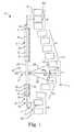
- FIG. 1is a schematic view of a corrective system secured along a spine tending to exhibit a defective curvature with a concave aspect, according to some embodiments.
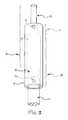
- FIG. 2shows a first connector and portions of a first rod and a middle assembling segment of the system of FIG. 1 , according to some embodiments.
- FIG. 3is a schematic view of a scoliotic spine before correction with the system of FIG. 1 , according to some embodiments.
- FIG. 4shows the spine of FIG. 3 after application of the system of FIG. 1 , according to some embodiments.
- FIG. 5shows the spine and system of FIG. 4 following spinal growth and elongation of the system, according to some embodiments.
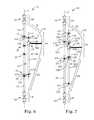
- FIG. 6is a schematic view of another corrective system secured along a spine tending to exhibit a defective curvature with a concave aspect, according to some embodiments.
- FIG. 7is schematic view of another corrective system secured along a spine tending to exhibit a defective curvature with a concave aspect, according to some embodiments.
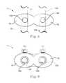
- FIG. 8is a top view of a dual-ring connector of the systems of FIGS. 6 and 7 , according to some embodiments.
- FIG. 9is a front view of the dual-ring connector of FIG. 8 , according to some embodiments.
- FIG. 10is a top view of a single-ring connector of the systems of FIGS. 6 and 7 , according to some embodiments.
- FIG. 11is a front view of the single-ring connector of FIG. 10 , according to some embodiments.
- FIG. 12is a top view of a lateral cross-section of another single-ring connector of the systems of FIGS. 6 and 7 , according to some embodiments.
- FIG. 13is a front view of the single-ring connector of FIG. 12 , according to some embodiments.
- FIG. 14shows a cross-section of a rod, according to some embodiments.
- FIG. 1is a schematic view of a system 10 for growth directed correction of a spine 12 via control of one or more apical vertebrae.
- the system 10is secured to a spine 12 along a concave aspect of its defective curvature.
- the system 10includes a hosting connector assembly 16 including a first connector 18 , a second connector 20 , and a middle assembling segment 22 .
- the system 10further includes a first rod 24 , a second rod 26 , and an intermediate connector assembly 28 .
- FIG. 2shows the first connector 18 and portions of the first rod 24 and the middle assembling segment 22 .
- the first and second rods 24 , 26are adapted to extend along the spine 12 and optionally differ in length as shown in FIG. 1 , although in other embodiments the first and second rods are substantially similar in length. In some embodiments, rod length is selected to allow a desired degree of growth of the spine 12 .
- the rods 24 , 26each optionally include an enlarged stop feature 30 , 32 having a larger diameter than adjacent portions of the respective rods 24 , 26 .
- the stop features 30 , 32 of the rods 24 , 26are thicker, shorter portions (e.g., with smooth rounded outline) which are hosted by wider areas of the connectors 18 , 20 and are allowed to slide within the respective connectors 18 , 20 until they abut narrower parts of the connectors.
- Each of the rods 24 , 26also includes thinner longer portions 36 , 38 .
- the spine 12generally includes five portions, where a defective segment of the spine 12 includes a proximal, or upper portion 40 ; a distal, or lower portion 42 ; and an apical portion, or apex 44 .
- the spine 12has a first portion 46 including one or more stabilizing vertebrae (e.g., a first vertebra 46 A) and a second portion 48 including one or more stabilizing vertebrae (e.g., a second vertebra 48 A).
- the stabilizing vertebraeare substantially aligned and are optionally fused during, prior to, or after assembly of the system 10 .
- the apical portion 44includes one or more vertebrae at the apex of the defect (e.g., a third vertebra 44 A, a fourth vertebra 44 B, and a fifth vertebra 44 C).
- the thinner portions 36 , 38 of the rods 24 , 26are adapted to host means of spinal fixation 34 , 35 , such as pedicle screws or hooks, to the first and second portions 46 , 48 of spine 12 at both ends of the defective segment 40 , 42 , 44 .
- the means of spinal fixation 34 , 35include pedicle screws or hooks used to secure the thinner longer portions 36 , 38 of the rods 24 , 26 to one or more vertebrae in each of the first and second portions 46 , 48 , respectively, of the spine 12 .
- each of the thinner longer portions 36 , 38is secured to the first and second vertebrae 46 A, 48 A, respectively, of the first and second portions 46 , 48 .
- one or both of the thinner longer portions 36 , 38are secured to multiple vertebrae, such as two adjacent stabilizing vertebrae of the first and second portions 46 , 48 , respectively (e.g., to provide additional support to the system 10 ).
- the middle assembling segment 22includes a body portion 22 A, such as a rod, a plate, or other structure for spanning between the first and second connectors 18 , 20 and to which a vertebra (e.g., a third vertebra 44 A in the apical portion 44 ) can be tensioned.
- the middle assembling segment 22also optionally includes an interconnect portion 22 B, such as a collar or a head of a pedicle screw, for connecting to the body portion 22 A.
- the intermediate connector assembly 28includes one or more elongate members, such as first elongate member 28 A, second elongate member 28 B, and third elongate member 28 C.
- the elongate members 28 A, 28 B, 28 Coptionally include one or more cables, wires, pedicle screws, hooks, rods, and/or other means for spanning between the interconnect portion 22 B of the middle assembling segment 22 and the apical portion 44 .
- the elongate members 28 A, 28 B, 28 Care optionally connected to the third, fourth, and fifth vertebrae 44 A, 44 B, 44 C of the apical portion 44 , respectively, by fastening means 49 , such as threaded fasteners, adhesives, hooks, sublaminar wires, and/or others.
- the first and second connectors 18 , 20optionally differ in length as shown in FIG. 1 , although in other embodiments the connectors 18 , 20 are substantially similar in length.
- the first and second connectors 18 , 20are adapted to extend along a desired spinal segment (e.g., including the upper and lower portions 40 , 42 ).
- the lengths of the first and second connectors 18 , 20are selected to allow a desired amount of longitudinal growth of the spine 12 , where the connectors 18 , 20 are each optionally cylindrical, having inner bores 50 , 52 that have narrowed, neck portions 54 , 56 and wider portions 58 , 60 such that the inner bores 50 , 52 include two parts with different diameters.
- the diameters of the wider portions 58 , 60 of the bores 50 , 52are larger than the diameters of the thicker, stop features 30 , 32 of the rods 24 , 26 to allow introduction of the rods 24 , 26 into the bores 50 , 52 , starting with the thinner portions 36 , 38 of the rods 24 , 26 which are first introduced through the openings into which the body portion 22 A of the middle assembling segment 22 is subsequently inserted and secured.
- the stop features 30 , 32 of the rods 24 , 26help retain the rods 24 , 26 in the inner bores 50 , 52 by engaging the narrowed or necked portions 54 , 56 of the connectors 18 , 20 and help prevent inadvertent ejection of the rods 24 , 26 from the connectors 18 , 20 .
- each of the connectors 18 , 20includes two means of fixation (e.g., set screws, pins, or others) for selectively locking a longitudinal position of the rods 24 , 26 with respect to the first and second connectors 18 , 20 , respectively.
- fixatione.g., set screws, pins, or others
- selectively lockingindicates that the longitudinal position is locked and unlocked as desired using the means of fixation of the first and second connectors 18 , 20 .
- independent control of each of the upper and lower portions 40 , 42 of the deformityis achieved by preselecting a desired amount that each of the first and second rods 24 , 26 is allowed to travel in the respective first and second connectors 18 , 20 (e.g., by selecting a length of the connectors 18 , 20 and rods 24 , 26 ) and/or by selectively locking the rods 24 , 26 using the means of fixation once a desired amount of growth is achieved.
- FIG. 2shows a first means of fixation 70 and a second means of fixation 72 of the first connector 18 , where according to some embodiments the second connector 20 includes similar means of fixation that operate similarly to the first and second means of fixation 70 , 72 (see FIGS. 4 and 5 ).
- the first and second means of fixation 70 , 72are located at each end of the connector 18 .
- the second means of fixation 72e.g., a set screw
- the first means of fixation 70is a temporary fixation point to fix the connector 18 to the thinner portion 36 of the rod 24 as desired.
- the means for fixation of the second connector 20optionally operate similarly and, by fixing the rods 24 , 26 to the connectors 18 , 20 , the rods 24 , 26 , and connectors 18 , 20 can be handled as one piece for ease of use during their insertion in the index surgery.
- the first means of fixation 70 of the first connector 18 and the first means of fixation (not shown) of the second connector 20are released (e.g., unscrewed and/or removed) at the end of the procedure to disengage the connectors 18 , 20 from the rods 24 , 26 to allow for gradual sliding of the rods 24 , 26 within the connectors 18 , 20 with growth of the spine 12 .
- the diameters of the narrower, or thinner portions 36 , 38 of the rods 24 , 26allow the thinner portions 36 , 38 of the rods 24 , 26 to go through the bores 50 , 52 , while the thicker stop features 30 , 32 prevent the rods 24 , 26 from ejecting from the bores 50 , 52 and limit sliding of the rods 24 , 26 to a desired range.
- the rods 24 , 26will slide in the connectors 18 , 20 with the thicker parts of the rods 24 , 26 moving out into the wider parts 58 , 60 of the bores 50 , 52 of the connectors 18 , 20 until they abut against the narrower, necked portions 54 , 56 of the bores 50 , 52 , preventing the rods 24 , 26 from further sliding.
- the length of the rods 24 , 26 and more generally the system 10will be exhausted and the system 10 will likely need to be adjusted by exchanging the rods 24 , 26 and/or connectors 18 , 20 to longer sizes.
- the body portion 22 A of the middle assembling segment 22is introduced into, and fixed to both wider ends of the bores 50 , 52 of the connectors 18 , 20 .
- the rods 24 , 26 , connectors 18 , 20 , and middle assembling segment 22define a correction axis X extending between the first and second vertebrae 46 A, 48 A.
- the body portion 22 A of the middle assembling segment 22is assembled to the interconnect portion 22 B which hosts the intermediate connector assembly 28 .
- the intermediate connector assembly 28optionally includes elongate members 28 A, 28 B, 28 C that include one or more of cables, wires, pedicle screws, hooks, or other means for spanning between the middle assembling segment 22 and the intermediate connector assembly 28 .
- the distance between the middle assembling segment 22 and the apical portion 44can be decreased by shortening the length of this fixation tool to tension or draw the apical portion 44 (e.g., the third vertebra 44 A) toward the correction axis X.
- Some methods of assemblyincludes coupling the first and second rods 24 , 26 with the first and second connectors 18 , 20 , and then coupling the first and second connectors 18 , 20 together with the middle assembling segment 22 .
- the thinner portions 36 , 38 of both rods 24 , 26extend out of the narrower openings or necked portions 54 , 56 of the corresponding connectors 18 , 20 .
- the thinner portions 36 , 38may then be attached to the spine 12 proximal and distal to the spinal deformity via vertebral fixation implants (e.g., hooks, screws, or others) at the first and second vertebrae 46 A, 48 A.
- both rods 24 , 26(stop features 30 , 32 ) will each be hosted inside the respective bores 50 , 52 of one of the connectors 18 , 20 near the wider portions 58 , 60 of the bores 50 , 52 and beside the middle assembling segment 22 to allow the rods 24 , 26 to slide inside the bores 50 , 52 during growth of the spine 12 .
- Both wider portions 58 , 60 of the bores 50 , 52 of the connectors 18 , 20receive the body portion 22 A of the middle assembling segment 22 which is then secured within the body portion 22 A.
- the elongate member(s) 28 A, 28 B, 28 C of the intermediate connector 28are secured to the interconnect portion 22 B of the middle assembling segment 22 and the elongate member(s) 28 A, 28 B, 28 C are secured to the third, fourth, and fifth vertebrae 44 A, 44 B, 44 C using the fastening means 49 to thereby fix and control the apical portion 44 with respect to the middle assembling segment 22 .
- Some methods of growth directed correction of the curvature with the system 10proceeds as follows.
- the system 10is applied and secured to the first portion 46 (e.g., first vertebra 46 A), the second portion 48 (e.g., second vertebra 48 A), and apical potion 44 (e.g., one or more of the third, fourth, and fifth vertebrae 44 A, 44 B, 44 C), for example, after maximum correction has been achieved by surgery.
- first portion 46e.g., first vertebra 46 A
- the second portion 48e.g., second vertebra 48 A
- apical potion 44e.g., one or more of the third, fourth, and fifth vertebrae 44 A, 44 B, 44 C
- both bulkier ends or stop features 30 , 32 of the rods 24 , 26will slide outwardly, away from the body portion 22 A within the first and second connectors 18 , 20 allowing for directed growth of the spine until the rods 24 , 26 are exhausted and the bulkier parts, or stop features 30 , 32 abut against the necked portions 54 , 56 of the connectors 18 , 20 and/or until the rods 24 , 26 are locked at a desired position via the fixation means (e.g., set screws) of the first and second connectors 18 , 20 .
- This interactionallows for spontaneous growth (e.g., several centimeters) and many years of growth while keeping the distance between the middle assembling segment 22 and the apical portion 44 .
- the distance between the middle assembling segment 22 and the apical portion 44is reduced using a specific instrument, such as a cable or wire tensioner (not shown).
- FIGS. 3-5A schematic representation of a method of growth directed correction is provided in FIGS. 3-5 , where FIG. 3 shows the spine 12 having a scoliotic curve (e.g., a severe curve greater than about 90 degrees) prior to application of the system 10 .
- FIG. 4shows the spine 12 and the system 10 after application of the system 10 .
- the system 10is secured to the spine 12 with some amount of apical correction during fixation (e.g., to a curve of about 59 degrees).
- partial correctionis accomplished by drawing the apical portion 44 toward the system 10 as part of the apical fixation process.
- FIG. 3shows the spine 12 having a scoliotic curve (e.g., a severe curve greater than about 90 degrees) prior to application of the system 10 .
- FIG. 4shows the spine 12 and the system 10 after application of the system 10 .
- the system 10is secured to the spine 12 with some amount of apical correction during fixation (e.g., to a curve
- FIGS. 4 and 5shows the system 10 and spine 12 following spinal growth (e.g., a few years later) where the spine 12 and the system 10 have elongated causing growth directed correction of the spine 12 resulting gradually and spontaneously without further intervention (e.g., to a curve of about 19 degrees).
- further intervention following some growthis contemplated to encourage and/or augment correction.
- such interventionoptionally includes reducing the distance between the system 10 and the apical portion 44 by tensioning and/or shortening one or more of associated elongate member(s) 28 (a single elongate member 28 A is shown in FIGS. 4 and 5 ).
- the system 10is easy to fabricate, is low profile such that it is suitable for all ages, and efficient and effective in use.
- the system 10is optionally assembled as a single construct via the temporary means of fixation between the rods 24 , 26 and connectors 18 , 20 , promoting ease of insertion and securement to the spine. Once implanted, the system 10 is optionally designed to work over the course of multiple years without substantial intervention.
- various embodimentsprovide a vertebral system 10 for correction and controlled growth of the spine 12 compromising rod(s) 24 , 26 , a hosting connector assembly 16 , and an intermediate connector assembly 28 .
- Embodimentsinclude rods 24 , 26 with different diameters of its both ends, where the bigger ends of the rods 24 , 26 are optionally smooth to allow sliding in first and second connectors 18 , 20 having end openings of different diameters.
- the connectors 18 , 20optionally have a wider openings to allow introduction of the rods 24 , 26 starting with their thinner then thicker parts inside the connectors 18 , 20 .
- the wider openingcan accommodate and be fixed to a middle assembling segment 22 of the system 10 via any stable means of fixation (e.g., set screws, threads, or others).
- the system 10includes a middle assembling segment 22 that includes a rod or plate which is attached to the intermediate connector assembly 28 , which is in turn secured to the apical portion 44 via vertebral fixation means (e.g., hooks, screws, wires, or other fastening means).
- the connectors 18 , 20provide temporary fixation (e.g., using set screws, pins, or others) to the rods 24 , 26 during assembly and insertion of the system 10 .
- the system 10is optionally to correct spinal deformities by allowing for growth of the spine 12 and promoting further gradual correction of the deformity with growth.
- the system 10is used for acute and gradual correction of spinal deformity which allows for spinal growth of the instrumented segment by elongating automatically with growth without the need for any intervention after insertion and connection to the spine 12 .
- the system 10includes a hosting connector assembly or assemblies 16 , special rod(s) 24 , 26 and intermediate connector(s) 28 .
- the rods 24 , 26are allowed to slide inside the hosting connector assembly 16 , in turn allowing for elongation of the whole system 10 and hence the instrumented part of the spine 12 .
- a middle assembling segment 22is fixed to the apex 44 of the deformity using an intermediate connector assembly 28 including one or more elongate members 28 A, 28 B, 28 C secured to the apex 44 using fastener means (e.g., pedicle screws, hooks, wires, cables, adhesives, and/or other means) to help prevent progressive rotation, angulation, or other deformity progression.
- fastener meanse.g., pedicle screws, hooks, wires, cables, adhesives, and/or other means
- first and second connector(s) 18 , 20each have a cavity made of two parts with different diameters and lengths—a longer wider part and shorter narrower one.
- the connector(s) 18 , 20each have one opening at each end, each opening has a different diameter which corresponds to its adjacent cavity.
- each rod 24 , 26has a thicker (bigger diameter) shorter part at the end of the rod 24 , 26 with the aim of preventing the rod 24 , 26 from dislodging from the smaller end opening of the corresponding connector 18 , 20 when the system 10 reaches its maximal length.
- Each wider cavity of the connector(s) 18 , 20can host and allow the passage of both parts of the rod(s) 24 , 26 while the narrower cavity of the connector(s) 18 , 20 can host only the thinner part of the rod(s) 24 , 26 , thereby preventing the thicker end of the rod(s) 24 , 26 from passing through the corresponding end opening of the connector(s) 18 , 20 .
- the middle assembling segment 22connects the two hosting connectors 18 , 20 together by being inserted into and secured within the wider openings and cavities of the connectors 18 , 20 .
- the rod(s) 24 , 26are introduced—their thinner parts first—into the wider openings of the connectors 18 , 20 and are fixed temporarily therein.
- the body portion 22 A of the middle assembling segment 22is then inserted into the wider ends and fixed therein to interconnect the two connectors 18 , 20 together.
- the body portion 22 A of the middle assembling segment 22is a rod shaped, or contoured to conform with a desired shape of the spine 12 in order to promote a proper sagittal contour of the spine 12 and decrease an incidence of implant failure, for example.
- the middle assembling segment 22is secured to the apical portion 44 by the intermediate connector 28 , which includes fastening means such as pedicle screws, hooks, wires, cables, and/or other fastening means for fastening to the vertebrae at the apex 44 of the deformity.
- the connector(s) 18 , 20have means of fixation (e.g., set screw, pins, and/or others) proximate each end—at the wider end to fix the connectors 18 , 20 to the middle assembling segment 22 and at the narrower end to fix the thinner part of the rods 24 , 26 temporarily during assembly and insertion and attachment of the system 10 to the spine 12 .
- the temporary means of fixation, or selective locking meansare removed at the end of the procedure to allow one or both of the rods 24 , 26 to slide in the connectors 18 , 20 and to allow the system 10 to elongate.
- the system 10optionally facilitates independent, separate control of each of the upper and lower portions 40 , 42 of a deformity, those upper and lower portions 40 , 42 being situated proximal and distal to an apical portion 44 of the deformity.
- a distance between each end of the system 10 and the apical portion 44increases independently with time and growth of the spine 12 , while the distance between the apical portion 44 and the system 10 is generally fixed or selectively adjusted (e.g., by tensioning the apical portion 44 toward the hosting connector assembly 16 ) allowing for gradual or gross spinal deformity curve correction.
- the first and second connectors 18 , 20optionally have different lengths, (e.g., to facilitate differing, independent, and preplanned control of the permissible growth and correction of the upper and lower portions 40 , 42 of the spine 12 ).
- a deformity angle and number of vertebrae included in each of the upper and lower portions 40 , 42are taken into consideration in determining an appropriate amount of travel between the first rod 24 and the first connector 18 and between the second rod 26 and the second connector 20 , where each of the first and second rods 24 , 26 is able to slide independently of the other rod inside its corresponding connector to facilitate independent elongation of the system 10 along the instrumented portions of the spine 12 above and below the apical portion 44 .
- the second mean of fixation of each of the first and second connectors 18 , 20can, at any time after the application of the system 10 , be tightened to limit further elongation of the corresponding upper or lower portion 40 , 42 of the spine 12 .
- the system 10is further adapted to promote independent correction of each of the upper and lower portions 40 , 42 as desired.
- a second systemsubstantially similar to the system 10 is optionally secured on an opposite side of the spine 12 for additional control.
- the system 10is shown secured on a concave lateral aspect of the spine 12 , it should be understood that, in some embodiments, the system 10 is secured on a convex lateral aspect of the spine 12 .
- FIG. 6shows another system 110 for growth directed correction of a spine 112 (schematically represented by a single line) via control of one or more apical vertebrae.
- the system 110includes a cascaded, or laterally offset feature, as subsequently described.
- the system 110is secured to the spine 112 along a concave aspect of its defective curvature.
- the system 110includes a hosting connector assembly 116 including a first connector 118 , a second connector 120 , and a middle assembling segment 122 .
- the system 110further includes a first rod 124 , a second rod 126 , and an intermediate connector 128 .
- the first and second rods 124 , 126are adapted to extend along the spine 112 and optionally differ in length as shown in FIG. 6 , although in other embodiments the first and second rods 124 , 126 are substantially similar in length. Regardless, in some embodiments, rod length is selected to allow a desired degree of growth of the spine 112 .
- the spine 112generally includes five portions, where a defective segment of the spine 112 includes a proximal, or upper portion 140 ; a distal, or lower portion 142 ; and an apical portion, or apex 144 .
- the spine 112has a first portion 146 including one or more stabilizing vertebrae and a second portion 148 including one or more stabilizing vertebrae.
- the stabilizing vertebraeare substantially aligned and are optionally fused during, prior to, or after assembly of the system 110 .
- the apical portion 144includes one or more vertebrae at the apex of the defect.
- the rods 124 , 126are adapted to host means of spinal fixation 134 , 135 for securing the first and second portions 146 , 148 of spine 112 at both ends of the defective segment 140 , 142 , 144 .
- the means of spinal fixation 134 , 135include pedicle screws, hooks, adhesive, or other fastening means used to secure the rods 124 , 126 to one or more vertebrae in each of the first and second portions 146 , 148 .
- the middle assembling segment 122includes a body portion 122 A, such as a rod, a plate, or other structure for spanning between the first and second connectors 118 , 120 and to which one or more vertebrae in the apical portion 144 is tensioned.
- the middle assembling segment 122also optionally includes an interconnect portion 122 B, such as a collar or a head of a pedicle screw or hook, for connecting to the body portion 122 A.
- the intermediate connector 128includes one or more elongate members, such as a first elongate member 128 A.
- the elongate member(s)optionally include one or more cables, wires, pedicle screws, rods, and/or other means for spanning between the middle assembling segment 122 and the apical portion 144 .
- the first and second connectors 118 , 120are substantially shorter than the connectors 18 , 20 of the system 10 .
- the first and second connectors 118 , 120are optionally about 10 mm in length (i.e., a direction substantially parallel to the longitudinal axes of the respective rods 124 , 126 ) or less.
- the first connector 118is adapted to slidably receive the first rod 124 and the middle assembling segment 122 .
- the second connector 120is adapted to slidably receive the second rod 126 and the middle assembling segment 122 .
- the connectors 118 , 120are optionally substantially similar and thus are described with reference to the first connector 118 , where FIGS. 8 and 9 are top and front views, respectively, of the first connector 118 .
- the first connector 118has a dual-ring shape, having a first ring portion 150 and a second ring potion 152 , the second ring portion 152 being interconnected with the first ring portion 150 .
- the first and second ring portions 150 , 152are optionally alternatively secured together by a rod or other connector. Indeed, although the two portions 150 , 152 are shown as a single piece, in other embodiments the two portions 150 , 152 are separate, connected components.
- the ring portions 150 , 152include central bores 150 A, 152 A for receiving the first rod 124 and the middle assembling segment 122 , respectively.
- the central bores 150 A, 152 Ahave entries and exits that are rounded to facilitate rod sliding and/or to avoid binding, for example.
- the central bores 150 A, 152 Aare substantially circular and smooth.
- the central bores 150 A, 152 Ainclude a prominence, or chase feature (such as chase feature 138 shown in FIGS. 12 and 13 ) for inhibiting longitudinal rotation of the rod 124 and/or the body portion 122 A in the central bores 150 A, 152 A.
- the rod 124 and/or body portion 122 Ainclude a complementary chase feature (such as chase 139 shown in FIG. 14 ) to the prominence so that the rod 124 and/or body portion 122 A and the bores 150 A, 152 A interlock, stopping longitudinal rotation of the rod 124 and/or body portion 122 A.
- the rod 124 and body portion 122 A and the bores 150 A, 152 Ahave complementary, non-circular cross-sections (square, octagonal, or D-shaped, for example) that mate to inhibit rotation of the rod 124 and body portion 122 A in the bores 150 A, 152 A, respectively.
- each of the connectors 118 , 120includes two means of fixation (e.g., set screws, pins, or others) 118 A, 118 B and 120 A, 120 B, respectively, for selectively locking a longitudinal position of the connectors 118 , 120 relative to the rods 124 , 126 and the middle assembling segment 122 .
- fixatione.g., set screws, pins, or others
- the means of fixation 118 A, 118 Bare set screws secured into the two portions 150 , 152 , respectively, such that adjustment of the first means of fixation 118 A selectively locks the first rod 124 in the first ring portion 150 and adjustment of the second means of fixation 118 B selectively locks the middle assembling segment 122 in the second ring portion 152 .
- an open hexagonis indicative that the means of fixation is in an unlocked configuration
- a solid hexagonis indicative that the means of fixation is in a locked configuration.
- the system 110includes stop features 130 , 132 that help prevent the rods from sliding toward one another, which could otherwise lead to reduction in the length of the system 110 in the longitudinal direction and loss of correction of the scoliosis angle.
- the stop features 130 , 132optionally help limit the rods 124 , 126 to sliding in a single direction—the direction of growth—and help prevent sliding in an opposite direction that would otherwise reduce overall system length.
- the stop features 130 , 132are rings, or collars, that include set screws 130 A, 132 A for securing the stop features 130 , 132 longitudinally along the first and second rods 124 , 126 , respectively.
- the system 110also includes stop features 136 , 137 that help prevent inadvertent ejection of the rods 124 , 126 from the connectors 118 , 120 .
- the stop features 136 , 137help ensure that the system 110 does not inadvertently disassemble after sufficient growth is achieved to cause the connectors to reach the ends of the rods 124 , 126 and/or under sufficient flexing of the spine 112 .
- the stop features 130 , 132 , 136 , 137are substantially similar to the first and second connectors 118 , 120 , but rather than first and second ring portions, only a single ring portion is present, according to some embodiments.
- FIGS. 10 and 11show the stop feature 130 from top and front views, respectively, the stop features 132 , 136 , 137 being substantially similar to the stop feature 130 according to some embodiments.
- each of the stop features 130 , 132 , 136 , 137includes a means of fixation (e.g., set screws, pins, or others) 130 A, 132 A, 136 A, 137 A, respectively, for selectively locking a longitudinal position of the stop features relative to the rods 124 , 126 .
- the means of fixation 130 A, 132 A, 136 A, 137 Aare set screws secured into the stop features 130 , 132 , 136 , 137 , respectively.
- adjustment of the means of fixation 130 Aselectively locks the first rod 124 in the stop feature 130 .
- an open hexagonis indicative that the means of fixation is in an unlocked configuration and a solid hexagon is indicative that the means of fixation is in a locked configuration.
- the stop feature 130has a single-ring shape, although multi-ring shapes are contemplated.
- the stop feature 130includes a central bore 130 B for receiving the first rod 124 .
- the central bore 130 Bhas an entry and an exit that are rounded to facilitate rod sliding and/or to avoid binding, for example.
- the central bore 130 Bis substantially circular and smooth, although non-rotational features are contemplated as described below.
- FIGS. 12 and 13show the stop feature 130 according to some other embodiments, where FIG. 12 is a cross-sectional view along line 12 - 12 in FIG. 13 .
- the central bore 130 Bincludes a prominence, or chase feature 138 for inhibiting longitudinal rotation of the rod 124 in the central bore 130 B.
- the chase feature 138is optionally a hemi-spherical bump or protrusion into the bore 130 B.
- the rod 124includes a chase feature 139 , such as a longitudinal groove or chase, that is complementary to the chase feature 138 such that that the rod 124 and the bore 130 B are adapted to interlock, helping prevent longitudinal rotation of the rod 124 in the bore 130 B.
- the rod 124 and the bore 130 Bhave complementary, non-circular cross-sections (square, octagonal, or D-shaped, for example) that mate to inhibit rotation of the rod 124 in the bore 130 B.
- the chase features 138 , 139are shown on the stop feature 130 and rod 124 , respectively, it should be understood that the chase features 138 , 139 are optionally reversed, with the chase feature 139 on the stop feature 130 and the chase feature 138 on the rod 124 .
- independent control of each of the upper and lower portions 140 , 142 of the deformityis achieved by preselecting a desired amount that each of the first and second rods 124 , 126 is allowed to travel in the respective first and second connectors 118 , 120 .
- the amount of travelis determined by selectively locking the stop features 130 , 132 , 136 , 137 longitudinally along the first and second rods 124 , 126 at a desired position to set limits of travel for the first and second rods 124 , 126 , respectively.
- Some methods of assembling the system 110include coupling the first and second rods 124 , 126 with the first and second connectors 118 , 120 , and then coupling the first and second connectors 118 , 120 to the middle assembling segment 122 .
- the rods 124 , 126extend out of the corresponding connectors 118 , 120 , with respective portions of the rods 124 , 126 being secured to the spine 112 proximal and distal to the spinal deformity via vertebral fixation implants (e.g., hooks, screws, or others) at the first and second portions 146 , 148 of the spine 112 .
- the first rod 124 and the second rod 126are hosted, or received, inside the bores of the respective connectors 118 , 120 and are allowed to slide inside the bores of the corresponding connectors 118 , 120 during growth of the spine 112 .
- Adjacent bores of the connectors 118 , 120receive the middle assembling segment 122 and are selectively locked to the body portion 122 A to provide system stability.
- the middle assembling segmentdefines a second axis of correction Y that is laterally offset, toward the spine 112 , relative to a first axis of correction X defined by the longitudinal axes of the rods 124 , 126 , the two rods 124 , 126 being coaxially aligned to one another according to some embodiments. In some embodiments, this offset brings the middle assembling segment 122 closer to the spine 112 reducing the length needed for the intermediate connector 128 .
- the intermediate connector 128is then secured to the apex 144 using fastening means such as those previously described (e.g., similar to fastening means 49 ).
- the respective stop features 130 , 132 , 136 , 137are received over the first and second rods 124 , 126 and are selectively locked thereto in order to help prevent the rods 124 , 126 from sliding toward one another (e.g., to avoid losing an amount of correction already achieved with the system 110 ) as well as help prevent the rods 124 , 126 from sliding out of the connectors 118 , 120 (e.g., after sufficient spinal growth and/or during flexing of the spine 112 ).
- an additional set of stop featuresare secured inwardly along the rods (e.g., toward the apical portion 144 of the spine 112 ) to set limits on the allowed longitudinal expansion of the system 110 .
- Some methods of growth directed correction of the curvature with the system 110proceeds as follows.
- the system 110is applied and secured to the first portion 146 , the second portion 148 , and the apical portion 144 , for example, after maximum correction has been achieved via surgery.
- both of the rods 124 , 126will slide outwardly, away from one another and adjacent to the body portion 122 A.
- the rods 124 , 126will continue to slide within the first and second connectors 118 , 120 , allowing for growth-directed correction of the spine 112 until the rods 124 , 126 are exhausted and/or until the rods 124 , 126 are locked at a desired position via the fixation means of the first and second connectors 118 , 120 .
- This interactionallows for spontaneous growth and/or movement (e.g., several centimeters) and many years of growth while maintaining a constant distance between the middle assembling segment 122 and the apical portion 144 .
- the distance between the middle assembling segment 122 and the apical portion 144is periodically reduced during growth using a specific instrument, such as a cable or wire tensioner (not shown).
- the system 110and in particular the relatively short connectors, help facilitate placement of the system 110 in relatively compact areas of the spine 112 (e.g., in scoliotic curved regions which provide little area for longer, more bulky connectors).
- a dorsal curve or an asymmetric curveregularly exhibits a relatively small distance between the stabilizing vertebrae and the apex in which a connector of about 50 mm in length may not fit.
- the dual-ring connectoris deployable in a very short segment of the spine 112 while allowing for considerable length of rod bending and sliding and, thus, growth directed correction.
- the stop features 130 , 132are optionally used to direct the force in a single, expanding direction by preventing compression and shortening of the system 110 without interfering with elongation thereof.
- FIG. 7is a schematic of another system 210 for growth directed correction of a spine 212 (schematically indicated by a single line) via control of one or more apical vertebrae.
- the system 210is secured to the spine 212 along a concave aspect of its defective curvature.
- the system 210includes a hosting connector assembly 216 including a first connector 218 , a second connector 220 , and a middle assembling segment 222 .
- the system 210further includes a first rod 224 , a second rod 226 , and an intermediate connector 228 .
- the first and second rods 224 , 226are adapted to extend along the spine 212 and optionally differ in length as shown in FIG. 7 , although in other embodiments the first and second rods 224 , 226 are substantially similar in length. Regardless, in some embodiments, rod length is selected to allow a desired degree of growth of the spine 212 .
- the spine 212generally includes five portions, where a defective segment of the spine 212 includes a proximal, or upper portion 240 ; a distal, or lower portion 242 ; and an apical portion, or apex 244 .
- a defective segment of the spine 212includes a proximal, or upper portion 240 ; a distal, or lower portion 242 ; and an apical portion, or apex 244 .
- the spine 212has a first portion 246 including one or more stabilizing vertebrae and a second portion 248 including one or more stabilizing vertebrae.
- the stabilizing vertebraeare substantially aligned and are optionally fused during, prior to, or after assembly of the system 210 .
- the apical portion 244includes one or more vertebrae at the apex of the defect.
- the rods 224 , 226are adapted to host means of spinal fixation 234 , 235 for securing the first and second portions 246 , 248 of spine 212 at both ends of the defective segments 240 , 242 .
- the means of spinal fixation 234 , 235include pedicle screws or hooks used to secure the rods 224 , 226 to one or more vertebrae in each of the first and second portions 246 , 248 .
- the middle assembling segment 222includes a body portion 222 A, such as a rod, a plate, or other structure for spanning between the first and second connectors 218 , 220 and to which one or more vertebrae in the apical portion 244 is tensioned.
- the middle assembling segment 222also optionally includes an interconnect portion 222 B, such as a collar or a head of a pedicle screw or hook, for connecting to the body portion 222 A.
- the intermediate connector 228includes one or more elongate members, such as a first elongate member 228 A.
- the elongate member(s)optionally include one or more cables, wires, pedicle screws, hooks, rods, and/or other means for spanning between the middle assembling segment 222 and the apical portion 244 .
- the first and second connectors 218 , 220are substantially similar to the first connector 118 shown in FIGS. 8 and 9 , the first and second connectors 218 , 220 being substantially shorter than the connectors 18 , 20 of the system 10 .
- the first connector 218is adapted to slidably receive the first rod 224 and the middle assembling segment 222 and the second connector 220 is adapted to slidably receive the second rod 226 and the middle assembling segment 222 , each of the first and second connectors 218 , 220 including first and second ring portions 250 , 252 and 254 , 256 , respectively.
- the ring portions 250 , 252include central bores for receiving the first rod 224 and the middle assembling segment 222 , respectively, and the ring portions 254 , 256 include central portions for receiving the second rod 226 and the middle assembling segment 222 , respectively.
- each of the connectors 218 , 220includes two means of fixation (e.g., set screws, pins, or others) 218 A, 218 B and 220 A, 220 B, respectively, for selectively locking a longitudinal position of the connectors 218 , 220 relative to the rods 224 , 226 and the middle assembling segment 222 .
- the means of fixation 218 A, 218 Bare optionally set screws secured into the ring portions 250 , 252 and 254 , 256 , respectively.
- Activation of the first means of fixation 218 Aselectively locks the first rod 224 in the first ring portion 250 and activation of the second means of fixation 218 B selectively locks the middle assembling segment 222 in the second ring portion 252 .
- Activation of the first means of fixation 220 Aselectively locks the second rod 226 in the first ring portion 254 and activation of the second means of fixation 220 B selectively locks the middle assembling segment 222 in the second ring portion 256 .
- an open hexagonis indicative that the means of fixation is in an unlocked configuration
- a solid hexagonis indicative that the means of fixation is in a locked configuration.
- the system 210includes stop features 230 , 233 that help retain the middle assembling segment 222 in the first and second connector assemblies 218 , 220 by preventing inadvertent ejection of the middle assembling segment 222 from the connectors 218 , 220 (e.g., after sufficient spinal growth and/or during flexing of the spine 212 ).
- the system 210also includes stop features 231 , 232 that help ensure that an achieved amount of correction of the spine 212 is not lost (e.g., due to compressive forces on the patient's spine—such as during standing).
- the stop features 230 , 231 , 232 , 233are rings, or collars, that include set screws 230 A, 231 A, 232 A, 233 A for securing the stop features 230 , 231 , 232 , 233 longitudinally along the middle assembling segment 222 .
- stop features 231 , 232help prevent collapse, or shortening of the system (e.g., under compressive forces of body weight) while stop features 230 , 233 help prevent ejection of the middle assembling segment 222 from the connector assemblies 218 , 220 once a length of the middle assembling segment 222 has been exhausted from spinal growth.
- the stop features 230 , 231 , 232 , 233are substantially similar to the first and second connectors 218 , 220 , but rather than first and second ring portions, only a single ring portion is present, according to some embodiments. Regardless, according to some embodiments, independent control of each of the upper and lower portions 240 , 242 of the deformity is achieved by preselecting a desired amount that the system 210 expands, or an amount that each of the first and second rods 224 , 226 is allowed to travel along the middle assembling segment 222 , by selectively locking the stop features 230 , 231 , 232 , 233 longitudinally at desired positions to set limits of travel for the first and second rods 224 , 226 , respectively.
- the stop features 230 , 231are locked on the middle assembling segment 222 on opposite sides of the first connector 218 and the stop features 232 , 233 are locked on the middle assembling segment 222 on opposite sides of the second connector 220 , to limit the travel of first and second connectors relative to the middle assembling segment 222 .
- Some methods of assembling the system 210include coupling the first and second rods 224 , 226 with the first and second connectors 218 , 220 , and then coupling the first and second connectors 218 , 220 to the middle assembling segment 222 .
- the rods 224 , 226extend out of the corresponding connectors 218 , 220 , with respective portions of the rods 224 , 226 being secured to the spine 212 proximal and distal to the spinal deformity via vertebral fixation implants (e.g., hooks, screws, or others) at the first and second portions 246 , 248 of the spine 212 .
- vertebral fixation implantse.g., hooks, screws, or others
- a first end 224 A of the first rod 224 and a first end 226 A of the second rod 226are hosted inside the bores of the respective connectors 218 , 220 and are selectively locked inside the bores of the corresponding connectors 218 , 220 during growth of the spine 212 .
- Adjacent bores of the connectors 218 , 220slidably receive the middle assembling segment 222 (although the connectors 218 , 220 are optionally locked to the middle assembling segment 222 during implantation to provide a rigid construct that is more readily handled, or to provide system stability).
- the middle assembling segment 222defines a second axis of correction Y that is laterally offset, toward the spine 212 , relative to a first axis of correction X defined by the longitudinal axes of the rods 224 , 226 , the two rods 224 , 226 being coaxially aligned to one another according to some embodiments.
- this offsetbrings the middle assembling segment 222 closer to the spine 212 reducing the length needed for the intermediate connector 228 .
- the intermediate connector 228is then secured to the apex 244 using fastening means such as those previously described (e.g., similar to fastening means 49 ).
- the respective stop features 230 , 231 , 232 , 233are received over the intermediate connector 228 and are selectively locked thereto in order to set limits between which the first and connectors 218 , 220 slide on the middle assembling segment.
- Some methods of growth directed correction of the curvature with the system 210proceeds as follows.
- the system 210is applied and secured to the first portion 246 , the second portion 248 , and the apical portion 244 , for example, after maximum correction has been achieved via surgery.
- both of the rods 224 , 226will slide outwardly, away from one another and adjacent to the body portion 222 A.
- the rods 224 , 226and in particular the first and second connectors 218 , 220 , will continue to slide along the middle assembling segment 222 , allowing for growth-directed correction of the spine 212 until the limit of travel is exhausted and/or until the rods 224 , 226 are locked at a desired position via the fixation means of the first and second connectors 218 , 220 .
- This interactionallows for spontaneous growth and/or movement (e.g., several centimeters) and many years of growth while maintaining a constant distance between the middle assembling segment 222 and the apical portion 244 .
- the distance between the middle assembling segment 222 and the apical portion 244is periodically reduced during growth using a specific instrument, such as a cable or wire tensioner (not shown).
- the system 210and in particular the relatively short connectors, help facilitate placement of the system 210 in relatively compact areas of the spine 212 (e.g., in scoliotic curved regions which provide little area for longer, more bulky connectors).
- a dorsal curve or an asymmetric curveregularly exhibits a relatively small distance between the stabilizing vertebrae and the apex in which a connector of about 50 mm in length may not fit.
- the dual-ring connectoris deployable in a very short segment of the spine 212 while allowing for considerable length of rod bending and sliding and, thus, growth directed correction.
- the stop features 230 , 232are optionally used to direct the force in a single, expanding direction by preventing compression and shortening of the system 210 without interfering with elongation thereof.
- the range of indication of embodiments of the systemsis wide enough to include any type of early onset spinal deformity of any etiology from the very young ages to the adolescent growth spurt, for example.
- One exemplary indicationis early onset scoliosis where the systems are used in young children to allow for growth of the spine, trunk, chest, and lungs while preventing progression of the scoliotic curve and even correcting the curve spontaneously with growth.
- the systemscan also be used in small and moderate sized curves during the adolescent period before severe progression as a kind of internal bracing to help prevent further progression of these defective curves until a child's growth spurt finishes.
- the systemsare removed, leaving a non-fused, relatively flexible, corrected spine.
Landscapes
- Health & Medical Sciences (AREA)
- Orthopedic Medicine & Surgery (AREA)
- Life Sciences & Earth Sciences (AREA)
- Neurology (AREA)
- Surgery (AREA)
- Heart & Thoracic Surgery (AREA)
- Engineering & Computer Science (AREA)
- Biomedical Technology (AREA)
- Nuclear Medicine, Radiotherapy & Molecular Imaging (AREA)
- Medical Informatics (AREA)
- Molecular Biology (AREA)
- Animal Behavior & Ethology (AREA)
- General Health & Medical Sciences (AREA)
- Public Health (AREA)
- Veterinary Medicine (AREA)
- Surgical Instruments (AREA)
- Prostheses (AREA)
Abstract
Description
Claims (9)
Priority Applications (10)
| Application Number | Priority Date | Filing Date | Title |
|---|---|---|---|
| US12/873,582US8828058B2 (en) | 2008-11-11 | 2010-09-01 | Growth directed vertebral fixation system with distractible connector(s) and apical control |
| PCT/US2011/049693WO2012030800A1 (en) | 2010-09-01 | 2011-08-30 | Growth directed vertebral fixation system with distractible connector(s) and apical control |
| JP2013527184AJP6067561B2 (en) | 2010-09-01 | 2011-08-30 | Vertebral fixation system using extendable coupler |
| EP11754962.6AEP2611372B1 (en) | 2010-09-01 | 2011-08-30 | Growth directed vertebral fixation system with distractible connector(s) and apical control |
| CN201180042465.8ACN103108598B (en) | 2010-09-01 | 2011-08-30 | Having can the growth guiding spinal fixation system that controls of traction connector and summit |
| AU2011296128AAU2011296128A1 (en) | 2010-09-01 | 2011-08-30 | Growth directed vertebral fixation system with distractible connector(s) and apical control |
| CA2809657ACA2809657C (en) | 2010-09-01 | 2011-08-30 | Growth directed vertebral fixation system with distractible connector(s) and apical control |
| US14/480,047US9510865B2 (en) | 2008-11-11 | 2014-09-08 | Growth directed vertebral fixation system with distractible connector(s) and apical control |
| US15/246,973US10842536B2 (en) | 2008-11-11 | 2016-08-25 | Growth directed vertebral fixation system with distractible connector(s) and apical control |
| US17/100,201US20210068869A1 (en) | 2008-11-11 | 2020-11-20 | Growth Directed Vertebral Fixation System With Distractible Connector(s) And Apical Control |
Applications Claiming Priority (4)
| Application Number | Priority Date | Filing Date | Title |
|---|---|---|---|
| EG2008111840AEG25692A (en) | 2008-11-11 | 2008-11-11 | Self expandable vertebral instrumentation system with apical deformity control |
| EG2008111840 | 2008-11-11 | ||
| PCT/US2009/063833WO2010056650A1 (en) | 2008-11-11 | 2009-11-10 | Growth directed vertebral fixation system with distractible connector(s) and apical control |
| US12/873,582US8828058B2 (en) | 2008-11-11 | 2010-09-01 | Growth directed vertebral fixation system with distractible connector(s) and apical control |
Related Parent Applications (1)
| Application Number | Title | Priority Date | Filing Date |
|---|---|---|---|
| PCT/US2009/063833Continuation-In-PartWO2010056650A1 (en) | 2008-11-11 | 2009-11-10 | Growth directed vertebral fixation system with distractible connector(s) and apical control |
Related Child Applications (1)
| Application Number | Title | Priority Date | Filing Date |
|---|---|---|---|
| US14/480,047DivisionUS9510865B2 (en) | 2008-11-11 | 2014-09-08 | Growth directed vertebral fixation system with distractible connector(s) and apical control |
Publications (2)
| Publication Number | Publication Date |
|---|---|
| US20110054536A1 US20110054536A1 (en) | 2011-03-03 |
| US8828058B2true US8828058B2 (en) | 2014-09-09 |
Family
ID=44588206
Family Applications (4)
| Application Number | Title | Priority Date | Filing Date |
|---|---|---|---|
| US12/873,582ActiveUS8828058B2 (en) | 2008-11-11 | 2010-09-01 | Growth directed vertebral fixation system with distractible connector(s) and apical control |
| US14/480,047Active2030-01-23US9510865B2 (en) | 2008-11-11 | 2014-09-08 | Growth directed vertebral fixation system with distractible connector(s) and apical control |
| US15/246,973Active2029-11-18US10842536B2 (en) | 2008-11-11 | 2016-08-25 | Growth directed vertebral fixation system with distractible connector(s) and apical control |
| US17/100,201AbandonedUS20210068869A1 (en) | 2008-11-11 | 2020-11-20 | Growth Directed Vertebral Fixation System With Distractible Connector(s) And Apical Control |
Family Applications After (3)
| Application Number | Title | Priority Date | Filing Date |
|---|---|---|---|
| US14/480,047Active2030-01-23US9510865B2 (en) | 2008-11-11 | 2014-09-08 | Growth directed vertebral fixation system with distractible connector(s) and apical control |
| US15/246,973Active2029-11-18US10842536B2 (en) | 2008-11-11 | 2016-08-25 | Growth directed vertebral fixation system with distractible connector(s) and apical control |
| US17/100,201AbandonedUS20210068869A1 (en) | 2008-11-11 | 2020-11-20 | Growth Directed Vertebral Fixation System With Distractible Connector(s) And Apical Control |
Country Status (7)
| Country | Link |
|---|---|
| US (4) | US8828058B2 (en) |
| EP (1) | EP2611372B1 (en) |
| JP (1) | JP6067561B2 (en) |
| CN (1) | CN103108598B (en) |
| AU (1) | AU2011296128A1 (en) |
| CA (1) | CA2809657C (en) |
| WO (1) | WO2012030800A1 (en) |
Cited By (48)
| Publication number | Priority date | Publication date | Assignee | Title |
|---|---|---|---|---|
| US20140236234A1 (en)* | 2011-06-03 | 2014-08-21 | Kspine, Inc. | Spinal correction system actuators |
| US20140249584A1 (en)* | 2012-04-24 | 2014-09-04 | Retrospine Pty Ltd | Segmental correction of lumbar lordosis |
| US9011491B2 (en) | 2004-08-03 | 2015-04-21 | K Spine, Inc. | Facet device and method |
| US9113959B2 (en) | 2011-11-16 | 2015-08-25 | K2M, Inc. | Spinal correction and secondary stabilization |
| US20150289906A1 (en)* | 2012-11-07 | 2015-10-15 | David Wycliffe Murray | Adjusting spinal curvature |
| WO2016134326A3 (en)* | 2015-02-19 | 2016-10-13 | Nuvasive, Inc. | Systems and methods for vertebral adjustment |
| US9510865B2 (en) | 2008-11-11 | 2016-12-06 | K2M, Inc. | Growth directed vertebral fixation system with distractible connector(s) and apical control |
| US9968379B2 (en) | 2012-10-04 | 2018-05-15 | Loubert S. Suddaby | Subcutaneous implantable device for gradually aligning a spine and subcutaneous implantable device for gradually lengthening a bone |
| US10016220B2 (en) | 2011-11-01 | 2018-07-10 | Nuvasive Specialized Orthopedics, Inc. | Adjustable magnetic devices and methods of using same |
| US10039661B2 (en) | 2006-10-20 | 2018-08-07 | Nuvasive Specialized Orthopedics, Inc. | Adjustable implant and method of use |
| US10188428B2 (en)* | 2017-05-15 | 2019-01-29 | Loubert S. Suddaby | Subcutaneous implantable device for gradually aligning a spine |
| US10271885B2 (en) | 2014-12-26 | 2019-04-30 | Nuvasive Specialized Orthopedics, Inc. | Systems and methods for distraction |
| US10342581B2 (en) | 2011-11-16 | 2019-07-09 | K2M, Inc. | System and method for spinal correction |
| US10349995B2 (en) | 2007-10-30 | 2019-07-16 | Nuvasive Specialized Orthopedics, Inc. | Skeletal manipulation method |
| US10405891B2 (en) | 2010-08-09 | 2019-09-10 | Nuvasive Specialized Orthopedics, Inc. | Maintenance feature in magnetic implant |
| US10478232B2 (en) | 2009-04-29 | 2019-11-19 | Nuvasive Specialized Orthopedics, Inc. | Interspinous process device and method |
| US10499954B2 (en) | 2016-03-10 | 2019-12-10 | Nuvasive, Inc. | Bone anchor with deployable purchase element |
| US10517643B2 (en) | 2009-02-23 | 2019-12-31 | Nuvasive Specialized Orthopedics, Inc. | Non-invasive adjustable distraction system |
| US10617453B2 (en) | 2015-10-16 | 2020-04-14 | Nuvasive Specialized Orthopedics, Inc. | Adjustable devices for treating arthritis of the knee |
| US10646262B2 (en) | 2011-02-14 | 2020-05-12 | Nuvasive Specialized Orthopedics, Inc. | System and method for altering rotational alignment of bone sections |
| US10660675B2 (en) | 2010-06-30 | 2020-05-26 | Nuvasive Specialized Orthopedics, Inc. | External adjustment device for distraction device |
| US10702311B2 (en) | 2011-11-16 | 2020-07-07 | K2M, Inc. | Spinal correction and secondary stabilization |
| US10729470B2 (en) | 2008-11-10 | 2020-08-04 | Nuvasive Specialized Orthopedics, Inc. | External adjustment device for distraction device |
| US10743794B2 (en) | 2011-10-04 | 2020-08-18 | Nuvasive Specialized Orthopedics, Inc. | Devices and methods for non-invasive implant length sensing |
| US10751094B2 (en) | 2013-10-10 | 2020-08-25 | Nuvasive Specialized Orthopedics, Inc. | Adjustable spinal implant |
| US10758274B1 (en) | 2014-05-02 | 2020-09-01 | Nuvasive, Inc. | Spinal fixation constructs and related methods |
| US10835290B2 (en) | 2015-12-10 | 2020-11-17 | Nuvasive Specialized Orthopedics, Inc. | External adjustment device for distraction device |
| US10918425B2 (en) | 2016-01-28 | 2021-02-16 | Nuvasive Specialized Orthopedics, Inc. | System and methods for bone transport |
| US11191579B2 (en) | 2012-10-29 | 2021-12-07 | Nuvasive Specialized Orthopedics, Inc. | Adjustable devices for treating arthritis of the knee |
| US11202707B2 (en) | 2008-03-25 | 2021-12-21 | Nuvasive Specialized Orthopedics, Inc. | Adjustable implant system |
| US11207110B2 (en) | 2009-09-04 | 2021-12-28 | Nuvasive Specialized Orthopedics, Inc. | Bone growth device and method |
| US11246694B2 (en) | 2014-04-28 | 2022-02-15 | Nuvasive Specialized Orthopedics, Inc. | System for informational magnetic feedback in adjustable implants |
| USRE49061E1 (en) | 2012-10-18 | 2022-05-10 | Nuvasive Specialized Orthopedics, Inc. | Intramedullary implants for replacing lost bone |
| US11357549B2 (en) | 2004-07-02 | 2022-06-14 | Nuvasive Specialized Orthopedics, Inc. | Expandable rod system to treat scoliosis and method of using the same |
| US11357547B2 (en) | 2014-10-23 | 2022-06-14 | Nuvasive Specialized Orthopedics Inc. | Remotely adjustable interactive bone reshaping implant |
| US11547450B2 (en)* | 2015-04-17 | 2023-01-10 | Apifix Ltd. | Expandable polyaxial spinal system |
| US11577097B2 (en) | 2019-02-07 | 2023-02-14 | Nuvasive Specialized Orthopedics, Inc. | Ultrasonic communication in medical devices |
| US11589901B2 (en) | 2019-02-08 | 2023-02-28 | Nuvasive Specialized Orthopedics, Inc. | External adjustment device |
| US11696836B2 (en) | 2013-08-09 | 2023-07-11 | Nuvasive, Inc. | Lordotic expandable interbody implant |
| US11737787B1 (en) | 2021-05-27 | 2023-08-29 | Nuvasive, Inc. | Bone elongating devices and methods of use |
| US11766252B2 (en) | 2013-07-31 | 2023-09-26 | Nuvasive Specialized Orthopedics, Inc. | Noninvasively adjustable suture anchors |
| US11801187B2 (en) | 2016-02-10 | 2023-10-31 | Nuvasive Specialized Orthopedics, Inc. | Systems and methods for controlling multiple surgical variables |
| US11806054B2 (en) | 2021-02-23 | 2023-11-07 | Nuvasive Specialized Orthopedics, Inc. | Adjustable implant, system and methods |
| US11839410B2 (en) | 2012-06-15 | 2023-12-12 | Nuvasive Inc. | Magnetic implants with improved anatomical compatibility |
| US11857226B2 (en) | 2013-03-08 | 2024-01-02 | Nuvasive Specialized Orthopedics | Systems and methods for ultrasonic detection of device distraction |
| US11925389B2 (en) | 2008-10-13 | 2024-03-12 | Nuvasive Specialized Orthopedics, Inc. | Spinal distraction system |
| US12023073B2 (en) | 2021-08-03 | 2024-07-02 | Nuvasive Specialized Orthopedics, Inc. | Adjustable implant |
| US12213708B2 (en) | 2020-09-08 | 2025-02-04 | Nuvasive Specialized Orthopedics, Inc. | Remote control module for adjustable implants |
Families Citing this family (21)
| Publication number | Priority date | Publication date | Assignee | Title |
|---|---|---|---|---|
| EP2155086B1 (en)* | 2007-06-06 | 2016-05-04 | K2M, Inc. | Medical device to correct deformity |
| US8357182B2 (en) | 2009-03-26 | 2013-01-22 | Kspine, Inc. | Alignment system with longitudinal support features |
| US20100318129A1 (en)* | 2009-06-16 | 2010-12-16 | Kspine, Inc. | Deformity alignment system with reactive force balancing |
| US9168071B2 (en)* | 2009-09-15 | 2015-10-27 | K2M, Inc. | Growth modulation system |
| US9084634B1 (en)* | 2010-07-09 | 2015-07-21 | Theken Spine, Llc | Uniplanar screw |
| US10603083B1 (en) | 2010-07-09 | 2020-03-31 | Theken Spine, Llc | Apparatus and method for limiting a range of angular positions of a screw |
| US9468469B2 (en) | 2011-11-16 | 2016-10-18 | K2M, Inc. | Transverse coupler adjuster spinal correction systems and methods |
| US9468468B2 (en) | 2011-11-16 | 2016-10-18 | K2M, Inc. | Transverse connector for spinal stabilization system |
| FR2988992B1 (en)* | 2012-04-04 | 2015-03-20 | Medicrea International | MATERIAL OF VERTEBRAL OSTEOSYNTHESIS |
| US9427261B2 (en) | 2012-06-13 | 2016-08-30 | Warsaw Orthopedic, Inc. | Spinal correction system and method |
| US9339306B2 (en)* | 2012-08-29 | 2016-05-17 | K2M, Inc. | Adjustable axial spinal rod connector |
| US9480519B2 (en)* | 2012-10-04 | 2016-11-01 | Loubert S. Suddaby | Apparatus for aligning a spine using deployable bone anchors and method for the same |
| US8764803B2 (en)* | 2012-10-04 | 2014-07-01 | Loubert S. Suddaby | Apparatus and method for aligning a spine |
| US9237907B2 (en)* | 2013-03-05 | 2016-01-19 | Warsaw Orthopedic, Inc. | Spinal correction system and method |
| US9468471B2 (en) | 2013-09-17 | 2016-10-18 | K2M, Inc. | Transverse coupler adjuster spinal correction systems and methods |
| US10507043B1 (en) | 2017-10-11 | 2019-12-17 | Seaspine Orthopedics Corporation | Collet for a polyaxial screw assembly |
| CN109394322B (en)* | 2018-10-18 | 2020-10-27 | 温州医科大学附属第二医院、温州医科大学附属育英儿童医院 | An extensible spinal internal fixation device for laterally fixing the bone position |
| CN109907807A (en)* | 2018-10-18 | 2019-06-21 | 温州医科大学附属第二医院、温州医科大学附属育英儿童医院 | An extensible spinal internal fixation device |
| CN110638512B (en)* | 2019-10-09 | 2021-02-12 | 温州医科大学附属第二医院、温州医科大学附属育英儿童医院 | Novel spinal deformity corrector |
| CN112022318B (en)* | 2020-09-22 | 2022-05-13 | 常州集硕医疗器械有限公司 | Spinal deformity growth fixing system and method |
| US20230032049A1 (en)* | 2021-07-29 | 2023-02-02 | David Skaggs | Systems and methods for treatment of spinal deformities |
Citations (431)
| Publication number | Priority date | Publication date | Assignee | Title |
|---|---|---|---|---|
| US2774350A (en) | 1952-09-08 | 1956-12-18 | Jr Carl S Cleveland | Spinal clamp or splint |
| GB780652A (en) | 1954-04-30 | 1957-08-07 | Zimmer Orthopaedic Ltd | Improvements in or relating to apparatus for use in spinal fixation |
| US3242922A (en) | 1963-06-25 | 1966-03-29 | Charles B Thomas | Internal spinal fixation means |
| US3352226A (en) | 1965-03-15 | 1967-11-14 | Silas E Nelsen | Infusion package |
| US3648691A (en) | 1970-02-24 | 1972-03-14 | Univ Colorado State Res Found | Method of applying vertebral appliance |
| US3693616A (en) | 1970-06-26 | 1972-09-26 | Robert Roaf | Device for correcting scoliotic curves |
| US3865105A (en) | 1973-05-16 | 1975-02-11 | Lode S Instr N V | Device for exerting forces on and fixing the spinal column of a human body |
| DE2644735A1 (en) | 1975-05-30 | 1977-04-07 | Erkki Einari Dipl Ing Nissinen | STRETCH AND SUPPORT DEVICE FOR THE SPINAL COLUMN |
| US4024588A (en) | 1974-10-04 | 1977-05-24 | Allo Pro A.G. | Artificial joints with magnetic attraction or repulsion |
| DE2845647A1 (en) | 1978-10-20 | 1980-05-08 | Messerschmitt Boelkow Blohm | Implanted surgical device for correcting spinal curvature - has correction rod rotated by motor to gradually shorten wire attached to spine |
| US4257409A (en)* | 1978-04-14 | 1981-03-24 | Kazimierz Bacal | Device for treatment of spinal curvature |
| US4269178A (en) | 1979-06-04 | 1981-05-26 | Keene James S | Hook assembly for engaging a spinal column |
| US4274401A (en) | 1978-12-08 | 1981-06-23 | Miskew Don B W | Apparatus for correcting spinal deformities and method for using |
| SU888968A1 (en) | 1979-01-11 | 1981-12-15 | Новосибирский научно-исследовательский институт травматологии и ортопедии | Apparatus for correcting vertebral column |
| US4355645A (en) | 1978-10-18 | 1982-10-26 | Kabushiki Kaisha Morita Seisakusho | Device for displaying masticatory muscle activities |
| US4361141A (en) | 1979-07-27 | 1982-11-30 | Zimmer Usa, Inc. | Scoliosis transverse traction assembly |
| US4369769A (en) | 1980-06-13 | 1983-01-25 | Edwards Charles C | Spinal fixation device and method |
| US4404967A (en) | 1982-01-18 | 1983-09-20 | Wyzsza Szkola Inzynierska Im. Jurija Gagarina | Surgical strut for treatment of the back-bone |
| US4411259A (en) | 1980-02-04 | 1983-10-25 | Drummond Denis S | Apparatus for engaging a hook assembly to a spinal column |
| US4411545A (en) | 1981-03-06 | 1983-10-25 | Skf Compagnie D'applications Mecaniques - Adr | Swivel joint |
| US4448191A (en) | 1981-07-07 | 1984-05-15 | Rodnyansky Lazar I | Implantable correctant of a spinal curvature and a method for treatment of a spinal curvature |
| US4505268A (en) | 1983-02-17 | 1985-03-19 | Vicente Sgandurra | Scoliosis frame |
| US4554914A (en) | 1983-10-04 | 1985-11-26 | Kapp John P | Prosthetic vertebral body |
| US4573454A (en) | 1984-05-17 | 1986-03-04 | Hoffman Gregory A | Spinal fixation apparatus |
| US4604995A (en) | 1984-03-30 | 1986-08-12 | Stephens David C | Spinal stabilizer |
| US4611581A (en) | 1983-12-16 | 1986-09-16 | Acromed Corporation | Apparatus for straightening spinal columns |
| US4611582A (en) | 1983-12-27 | 1986-09-16 | Wisconsin Alumni Research Foundation | Vertebral clamp |
| US4634445A (en) | 1981-01-30 | 1987-01-06 | Oec Europe Limited | Joint prosthesis |
| US4648388A (en) | 1985-11-01 | 1987-03-10 | Acromed Corporation | Apparatus and method for maintaining vertebrae in a desired relationship |
| US4653481A (en) | 1985-07-24 | 1987-03-31 | Howland Robert S | Advanced spine fixation system and method |
| US4658809A (en) | 1983-02-25 | 1987-04-21 | Firma Heinrich C. Ulrich | Implantable spinal distraction splint |
| US4697582A (en) | 1983-10-28 | 1987-10-06 | Peze William | Appliance for correcting rachidial deformities |
| EP0260044A1 (en) | 1986-08-29 | 1988-03-16 | John Anthony Norman Shepperd | Spinal implant |
| US4738251A (en) | 1987-02-20 | 1988-04-19 | Codespi, Corporation | Correcting device for spine pathology |
| US4773402A (en) | 1985-09-13 | 1988-09-27 | Isola Implants, Inc. | Dorsal transacral surgical implant |
| US4805602A (en) | 1986-11-03 | 1989-02-21 | Danninger Medical Technology | Transpedicular screw and rod system |
| US4815453A (en) | 1983-05-04 | 1989-03-28 | Societe De Fabrication De Materiel Orthopedique (Sofamor) | Device for supporting the rachis |
| US4827918A (en) | 1985-08-15 | 1989-05-09 | Sven Olerud | Fixing instrument for use in spinal surgery |
| EP0322334A1 (en) | 1987-12-23 | 1989-06-28 | Cremascoli France | Prosthesis implanted between vertebral spinous processes |
| US4854311A (en) | 1986-01-09 | 1989-08-08 | Acro Med Corporation | Bone screw |
| US4931055A (en)* | 1986-05-30 | 1990-06-05 | John Bumpus | Distraction rods |
| US4936848A (en) | 1989-09-22 | 1990-06-26 | Bagby George W | Implant for vertebrae |
| US5000166A (en) | 1988-04-27 | 1991-03-19 | Sulzer Brothers Limited | Implant kit for stabilizing regions of a spine |
| EP0418387A1 (en) | 1989-02-21 | 1991-03-27 | Vsesojuzny Kurgansky Nauchny Tsentr "Vosstanovitelnaya Travmatologia I Ortopedia" | Device for treatment of curvature of and damage to the spine |
| US5005562A (en) | 1988-06-24 | 1991-04-09 | Societe De Fabrication De Material Orthopedique | Implant for spinal osteosynthesis device, in particular in traumatology |
| US5011484A (en) | 1987-11-16 | 1991-04-30 | Breard Francis H | Surgical implant for restricting the relative movement of vertebrae |
| US5030220A (en) | 1990-03-29 | 1991-07-09 | Advanced Spine Fixation Systems Incorporated | Spine fixation system |
| US5042982A (en) | 1987-07-08 | 1991-08-27 | Harms Juergen | Positioning device |
| US5084049A (en) | 1989-02-08 | 1992-01-28 | Acromed Corporation | Transverse connector for spinal column corrective devices |
| US5092867A (en) | 1988-07-13 | 1992-03-03 | Harms Juergen | Correction and supporting apparatus, in particular for the spinal column |
| US5092866A (en) | 1989-02-03 | 1992-03-03 | Breard Francis H | Flexible inter-vertebral stabilizer as well as process and apparatus for determining or verifying its tension before installation on the spinal column |
| US5127912A (en) | 1990-10-05 | 1992-07-07 | R. Charles Ray | Sacral implant system |
| US5129900A (en) | 1990-07-24 | 1992-07-14 | Acromed Corporation | Spinal column retaining method and apparatus |
| US5133716A (en) | 1990-11-07 | 1992-07-28 | Codespi Corporation | Device for correction of spinal deformities |
| US5147363A (en) | 1989-12-21 | 1992-09-15 | Haerle Anton | Screw for use in osteosynthesis |
| US5176680A (en) | 1990-02-08 | 1993-01-05 | Vignaud Jean Louis | Device for the adjustable fixing of spinal osteosynthesis rods |
| US5176679A (en) | 1991-09-23 | 1993-01-05 | Lin Chih I | Vertebral locking and retrieving system |
| US5181917A (en) | 1990-06-19 | 1993-01-26 | Chaim Rogozinski | System and method for instrumentation of the spine in the treatment of spinal deformities |
| US5190543A (en) | 1990-11-26 | 1993-03-02 | Synthes (U.S.A.) | Anchoring device |
| US5207678A (en) | 1989-07-20 | 1993-05-04 | Prufer | Pedicle screw and receiver member therefore |
| US5209752A (en) | 1991-12-04 | 1993-05-11 | Danek Medical, Inc. | Lateral offset connector for spinal implant system |
| US5219349A (en) | 1991-02-15 | 1993-06-15 | Howmedica, Inc. | Spinal fixator reduction frame |
| US5242443A (en) | 1991-08-15 | 1993-09-07 | Smith & Nephew Dyonics, Inc. | Percutaneous fixation of vertebrae |
| US5254118A (en) | 1991-12-04 | 1993-10-19 | Srdjian Mirkovic | Three dimensional spine fixation system |
| US5257994A (en) | 1991-09-23 | 1993-11-02 | Lin Chih I | Vertebral locking and retrieving system |
| US5259398A (en) | 1989-10-26 | 1993-11-09 | Giuseppe Vrespa | Method for fixing prosthesis to bones |
| US5282862A (en) | 1991-12-03 | 1994-02-01 | Artifex Ltd. | Spinal implant system and a method for installing the implant onto a vertebral column |
| US5306275A (en) | 1992-12-31 | 1994-04-26 | Bryan Donald W | Lumbar spine fixation apparatus and method |
| FR2697744A1 (en) | 1992-11-10 | 1994-05-13 | Fabrication Mat Orthopedique S | Spinal osteosynthesis instrumentation by the anterior route. |
| US5312410A (en) | 1992-12-07 | 1994-05-17 | Danek Medical, Inc. | Surgical cable tensioner |
| US5312420A (en) | 1992-10-09 | 1994-05-17 | United States Surgical Corporation | Surgical apparatus for removing fasteners |
| US5330473A (en) | 1993-03-04 | 1994-07-19 | Advanced Spine Fixation Systems, Inc. | Branch connector for spinal fixation systems |
| US5330474A (en) | 1991-09-23 | 1994-07-19 | Lin Chih I | Vertebral locking and retrieving system |
| US5352226A (en) | 1993-02-08 | 1994-10-04 | Lin Chih I | Side locking system rotatable in all directions for use in spinal surgery |
| US5360431A (en) | 1990-04-26 | 1994-11-01 | Cross Medical Products | Transpedicular screw system and method of use |
| US5366455A (en) | 1988-11-04 | 1994-11-22 | Surgicraft Limited | Pedicle engaging means |
| US5368594A (en) | 1991-09-30 | 1994-11-29 | Fixano S.A. | Vertebral osteosynthesis device |
| US5380323A (en) | 1993-06-16 | 1995-01-10 | Advanced Spine Fixation Systems, Inc. | Clamps for spinal fixation systems |
| US5380325A (en) | 1992-11-06 | 1995-01-10 | Biomat | Osteosynthesis device for spinal consolidation |
| US5382248A (en) | 1992-09-10 | 1995-01-17 | H. D. Medical, Inc. | System and method for stabilizing bone segments |
| US5387212A (en) | 1993-01-26 | 1995-02-07 | Yuan; Hansen A. | Vertebral locking and retrieving system with central locking rod |
| US5387213A (en) | 1991-02-05 | 1995-02-07 | Safir S.A.R.L. | Osseous surgical implant particularly for an intervertebral stabilizer |
| US5391168A (en) | 1992-04-01 | 1995-02-21 | Acromed B.V. | Device for correcting the shape of the human spinal column and/or for fixing the human spinal column |
| US5397363A (en) | 1992-08-11 | 1995-03-14 | Gelbard; Steven D. | Spinal stabilization implant system |
| US5413576A (en) | 1993-02-10 | 1995-05-09 | Rivard; Charles-Hilaire | Apparatus for treating spinal disorder |
| US5436542A (en) | 1994-01-28 | 1995-07-25 | Surgix, Inc. | Telescopic camera mount with remotely controlled positioning |
| US5437671A (en) | 1992-03-10 | 1995-08-01 | Zimmer, Inc. | Perpendicular rod connector for spinal fixation device |
| US5437669A (en) | 1993-08-12 | 1995-08-01 | Amei Technologies Inc. | Spinal fixation systems with bifurcated connectors |
| US5456722A (en) | 1993-01-06 | 1995-10-10 | Smith & Nephew Richards Inc. | Load bearing polymeric cable |
| US5466238A (en) | 1993-08-27 | 1995-11-14 | Lin; Chih-I | Vertebral locking and retrieving system having a fixation crossbar |
| US5470333A (en) | 1993-03-11 | 1995-11-28 | Danek Medical, Inc. | System for stabilizing the cervical and the lumbar region of the spine |
| US5480440A (en) | 1991-08-15 | 1996-01-02 | Smith & Nephew Richards, Inc. | Open surgical technique for vertebral fixation with subcutaneous fixators positioned between the skin and the lumbar fascia of a patient |
| US5486174A (en) | 1993-02-24 | 1996-01-23 | Soprane S.A. | Fastener for the osteosynthesis of the spinal column |
| US5487744A (en) | 1993-04-08 | 1996-01-30 | Advanced Spine Fixation Systems, Inc. | Closed connector for spinal fixation systems |
| US5490851A (en) | 1994-08-02 | 1996-02-13 | Nenov; Nikolay N. | Method and apparatus for treatment of idiopathic scoliosis |
| US5496318A (en) | 1993-01-08 | 1996-03-05 | Advanced Spine Fixation Systems, Inc. | Interspinous segmental spine fixation device |
| US5498262A (en) | 1992-12-31 | 1996-03-12 | Bryan; Donald W. | Spinal fixation apparatus and method |
| US5501684A (en) | 1992-06-25 | 1996-03-26 | Synthes (U.S.A.) | Osteosynthetic fixation device |
| US5520688A (en) | 1994-07-20 | 1996-05-28 | Lin; Chih-I | Vertebral auxiliary fixation device |
| US5527314A (en) | 1993-01-04 | 1996-06-18 | Danek Medical, Inc. | Spinal fixation system |
| US5540689A (en) | 1990-05-22 | 1996-07-30 | Sanders; Albert E. | Apparatus for securing a rod adjacent to a bone |
| US5544993A (en) | 1993-12-13 | 1996-08-13 | H+E,Uml A+Ee Rle; Anton | Threaded fastener |
| US5549679A (en) | 1994-05-20 | 1996-08-27 | Kuslich; Stephen D. | Expandable fabric implant for stabilizing the spinal motion segment |
| US5562660A (en) | 1993-02-09 | 1996-10-08 | Plus Endoprothetik Ag | Apparatus for stiffening and/or correcting the vertebral column |
| US5569246A (en) | 1993-12-28 | 1996-10-29 | Asahi Kogaku Kogyo Kabushiki Kaisha | Fixing instrument for spinal fusion members |
| US5571191A (en) | 1995-03-16 | 1996-11-05 | Fitz; William R. | Artificial facet joint |
| US5575791A (en) | 1994-07-27 | 1996-11-19 | Lin; Chih-I | Universal eccentric fixation mechanism for orthopedic surgery |
| US5584626A (en) | 1995-06-15 | 1996-12-17 | Excelsior Development Inc. | Torque-limiting fastening element |
| US5586983A (en) | 1990-05-22 | 1996-12-24 | Sanders; Albert E. | Bone clamp of shape memory material |
| US5591165A (en) | 1992-11-09 | 1997-01-07 | Sofamor, S.N.C. | Apparatus and method for spinal fixation and correction of spinal deformities |
| FR2736535A1 (en) | 1995-07-10 | 1997-01-17 | Martin Jean Jacques | Spinal osteosynthesis device to immobilise portion of spine e.g. in case of pathological degeneration between vertebrae |
| US5601554A (en) | 1993-03-04 | 1997-02-11 | Advanced Spine Fixation Systems, Inc. | Branch connector for spinal fixation systems |
| US5611800A (en) | 1994-02-15 | 1997-03-18 | Alphatec Manufacturing, Inc. | Spinal fixation system |
| US5620443A (en) | 1995-01-25 | 1997-04-15 | Danek Medical, Inc. | Anterior screw-rod connector |
| US5630816A (en) | 1995-05-01 | 1997-05-20 | Kambin; Parviz | Double barrel spinal fixation system and method |
| US5643259A (en) | 1994-03-31 | 1997-07-01 | Ricardo C. Sasso | Spine fixation instrumentation |
| US5645599A (en) | 1994-07-26 | 1997-07-08 | Fixano | Interspinal vertebral implant |
| US5649926A (en) | 1994-07-14 | 1997-07-22 | Advanced Spine Fixation Systems, Inc. | Spinal segmental reduction derotational fixation system |
| US5658284A (en) | 1994-06-30 | 1997-08-19 | Allo Pro Ag | Connection member for the connection of a resilient rod with a bone screw which can be anchored in a vertebra |
| US5672175A (en) | 1993-08-27 | 1997-09-30 | Martin; Jean Raymond | Dynamic implanted spinal orthosis and operative procedure for fitting |
| US5676703A (en) | 1994-05-11 | 1997-10-14 | Gelbard; Steven D. | Spinal stabilization implant system |
| US5702399A (en) | 1996-05-16 | 1997-12-30 | Pioneer Laboratories, Inc. | Surgical cable screw connector |
| US5702395A (en) | 1992-11-10 | 1997-12-30 | Sofamor S.N.C. | Spine osteosynthesis instrumentation for an anterior approach |
| US5702452A (en) | 1995-01-23 | 1997-12-30 | Sofamor S.N.C. | Spinal osteosynthesis device with median hook and vertebral anchoring support |
| US5704936A (en) | 1992-04-10 | 1998-01-06 | Eurosurgical | Spinal osteosynthesis device |
| US5713898A (en) | 1993-05-18 | 1998-02-03 | Schafer Micomed Gmbh | Orthopedic surgical holding device |
| US5716355A (en) | 1995-04-10 | 1998-02-10 | Sofamor Danek Group, Inc. | Transverse connection for spinal rods |
| US5725582A (en) | 1992-08-19 | 1998-03-10 | Surgicraft Limited | Surgical implants |
| US5728097A (en) | 1992-03-17 | 1998-03-17 | Sdgi Holding, Inc. | Method for subcutaneous suprafascial internal fixation |
| US5733284A (en) | 1993-08-27 | 1998-03-31 | Paulette Fairant | Device for anchoring spinal instrumentation on a vertebra |
| US5735852A (en) | 1995-05-22 | 1998-04-07 | Synthes (U.S.A.) | Clamp jaw for a spinal affixation device |
| US5782831A (en) | 1996-11-06 | 1998-07-21 | Sdgi Holdings, Inc. | Method an device for spinal deformity reduction using a cable and a cable tensioning system |
| US5797910A (en) | 1993-08-27 | 1998-08-25 | Paulette Fairant | Operative equipment for correcting a spinal deformity |
| US5810817A (en) | 1992-06-19 | 1998-09-22 | Roussouly; Pierre | Spinal therapy apparatus |
| US5810819A (en) | 1997-05-15 | 1998-09-22 | Spinal Concepts, Inc. | Polyaxial pedicle screw having a compression locking rod gripping mechanism |
| US5814046A (en) | 1992-11-13 | 1998-09-29 | Sofamor S.N.C. | Pedicular screw and posterior spinal instrumentation |
| US5885285A (en) | 1995-08-14 | 1999-03-23 | Simonson; Peter Melott | Spinal implant connection assembly |
| US5891145A (en) | 1997-07-14 | 1999-04-06 | Sdgi Holdings, Inc. | Multi-axial screw |
| US5902305A (en) | 1996-07-11 | 1999-05-11 | Aesculap Ag & Co. Kg | Surgical tensioning device |
| US5910142A (en) | 1998-10-19 | 1999-06-08 | Bones Consulting, Llc | Polyaxial pedicle screw having a rod clamping split ferrule coupling element |
| US5928232A (en) | 1994-11-16 | 1999-07-27 | Advanced Spine Fixation Systems, Incorporated | Spinal fixation system |
| US5938663A (en) | 1995-03-06 | 1999-08-17 | Stryker France, S.A. | Spinal instruments, particularly for a rod |
| US5947967A (en) | 1997-10-22 | 1999-09-07 | Sdgt Holdings, Inc. | Variable angle connector |
| US5964769A (en) | 1997-08-26 | 1999-10-12 | Spinal Concepts, Inc. | Surgical cable system and method |
| US5976135A (en) | 1997-12-18 | 1999-11-02 | Sdgi Holdings, Inc. | Lateral connector assembly |
| US5980521A (en) | 1995-03-30 | 1999-11-09 | Sdgi Holdings,Inc. | Top-tightening transverse connector for a spinal fixation system |
| US5984924A (en) | 1998-10-07 | 1999-11-16 | Isola Implants, Inc. | Bone alignment system having variable orientation bone anchors |
| US5989256A (en) | 1999-01-19 | 1999-11-23 | Spineology, Inc. | Bone fixation cable ferrule |
| US6015409A (en) | 1994-05-25 | 2000-01-18 | Sdgi Holdings, Inc. | Apparatus and method for spinal fixation and correction of spinal deformities |
| FR2781359A1 (en) | 1998-07-21 | 2000-01-28 | Pierre Boccara | Osteosynthesis frame for spinal surgery has rod with clamps to hold cross bars with anchor screws |
| US6039738A (en) | 1997-07-03 | 2000-03-21 | Depuy Orthopaedics, Inc. | Fastener |
| US6053921A (en) | 1997-08-26 | 2000-04-25 | Spinal Concepts, Inc. | Surgical cable system and method |
| US6077268A (en) | 1994-03-29 | 2000-06-20 | Sdgi Holdings, Inc. | Variable angle surgical cable crimp assembly and method |
| US6086590A (en) | 1999-02-02 | 2000-07-11 | Pioneer Laboratories, Inc. | Cable connector for orthopaedic rod |
| US6101678A (en)* | 1998-11-13 | 2000-08-15 | Invacare Corporation | Adjustable handle for a manually movable vehicle |
| US6110173A (en) | 1998-09-15 | 2000-08-29 | Advanced Spine Fixation Systems, Inc. | Transverse connector for spinal fixation systems |
| US6123706A (en) | 1997-12-17 | 2000-09-26 | Lange; Robert | Apparatus for stabilizing certain vertebrae of the spine |
| US6132431A (en) | 1996-04-18 | 2000-10-17 | Tresona Instrument Ab | Device and method for correcting and stabilizing a deviating curvature of a spinal column |
| US6132464A (en) | 1994-06-24 | 2000-10-17 | Paulette Fairant | Vertebral joint facets prostheses |
| US6136000A (en) | 1996-01-19 | 2000-10-24 | Louis; Rene | Anchoring device for posterior vertebral osteosynthesis |
| US6176861B1 (en) | 1994-10-25 | 2001-01-23 | Sdgi Holdings, Inc. | Modular spinal system |
| US6231575B1 (en) | 1998-08-27 | 2001-05-15 | Martin H. Krag | Spinal column retainer |
| FR2801492A1 (en) | 1999-11-30 | 2001-06-01 | Jean Jacques Martin | Gliding joint device for spinal support to ensure vertebrae are correctly aligned and treatment of spinal conditions in which the vertebrae require support, has improved positioning mechanism using tightening wires |
| US6248106B1 (en) | 2000-02-25 | 2001-06-19 | Bret Ferree | Cross-coupled vertebral stabilizers |
| US6251111B1 (en) | 1999-10-20 | 2001-06-26 | Sdgi Holdings, Inc. | Jack for pulling a vertebral anchor |
| US6261288B1 (en) | 2000-02-08 | 2001-07-17 | Roger P. Jackson | Implant stabilization and locking system |
| US6273914B1 (en) | 1995-09-28 | 2001-08-14 | Sparta, Inc. | Spinal implant |
| US6277120B1 (en) | 2000-09-20 | 2001-08-21 | Kevin Jon Lawson | Cable-anchor system for spinal fixation |
| US6283967B1 (en) | 1999-12-17 | 2001-09-04 | Synthes (U.S.A.) | Transconnector for coupling spinal rods |
| US6293949B1 (en) | 2000-03-01 | 2001-09-25 | Sdgi Holdings, Inc. | Superelastic spinal stabilization system and method |
| US6296643B1 (en) | 1999-04-23 | 2001-10-02 | Sdgi Holdings, Inc. | Device for the correction of spinal deformities through vertebral body tethering without fusion |
| US6299613B1 (en) | 1999-04-23 | 2001-10-09 | Sdgi Holdings, Inc. | Method for the correction of spinal deformities through vertebral body tethering without fusion |
| US20010037111A1 (en) | 2000-05-08 | 2001-11-01 | Dixon Robert A. | Method and apparatus for dynamized spinal stabilization |
| US6325805B1 (en) | 1999-04-23 | 2001-12-04 | Sdgi Holdings, Inc. | Shape memory alloy staple |
| US6328739B1 (en) | 1999-05-04 | 2001-12-11 | Industrial Technology Research Institute | Enhanced spine fixation apparatus |
| US20020032442A1 (en)* | 2000-06-09 | 2002-03-14 | Moti Altarac | Adjustable transverse connector for use with a spinal implant system |
| US6358254B1 (en) | 2000-09-11 | 2002-03-19 | D. Greg Anderson | Method and implant for expanding a spinal canal |
| US6364883B1 (en) | 2001-02-23 | 2002-04-02 | Albert N. Santilli | Spinous process clamp for spinal fusion and method of operation |
| US6364885B1 (en) | 1994-02-24 | 2002-04-02 | Pioneer Laboratories, Inc. | Cable tensioning device |
| US6402749B1 (en) | 1999-04-21 | 2002-06-11 | Sdgi Holdings, Inc. | Variable angle connection assembly for a spinal implant system |
| US6402752B2 (en) | 2000-02-07 | 2002-06-11 | Ulrich Gmbh & Co. Kg | Polyaxial pedicle-screw |
| US6419703B1 (en) | 2001-03-01 | 2002-07-16 | T. Wade Fallin | Prosthesis for the replacement of a posterior element of a vertebra |
| US6423065B2 (en) | 2000-02-25 | 2002-07-23 | Bret A. Ferree | Cross-coupled vertebral stabilizers including cam-operated cable connectors |
| US6451019B1 (en) | 1998-10-20 | 2002-09-17 | St. Francis Medical Technologies, Inc. | Supplemental spine fixation device and method |
| US20020133155A1 (en) | 2000-02-25 | 2002-09-19 | Ferree Bret A. | Cross-coupled vertebral stabilizers incorporating spinal motion restriction |
| US6458131B1 (en) | 2000-08-07 | 2002-10-01 | Salut, Ltd. | Apparatus and method for reducing spinal deformity |
| US20020143329A1 (en) | 2001-03-30 | 2002-10-03 | Serhan Hassan A. | Intervertebral connection system |
| US20020151978A1 (en) | 1996-07-22 | 2002-10-17 | Fred Zacouto | Skeletal implant |
| US6488683B2 (en) | 2000-11-08 | 2002-12-03 | Cleveland Clinic Foundation | Method and apparatus for correcting spinal deformity |
| US6514255B1 (en) | 2000-02-25 | 2003-02-04 | Bret Ferree | Sublaminar spinal fixation apparatus |
| EP1281361A1 (en) | 2001-08-02 | 2003-02-05 | Lafitt, S.A. | Device to prevent intervertebral disk degeneration |
| US6520962B1 (en) | 2000-10-23 | 2003-02-18 | Sdgi Holdings, Inc. | Taper-locked adjustable connector |
| US20030040746A1 (en) | 2001-07-20 | 2003-02-27 | Mitchell Margaret E. | Spinal stabilization system and method |
| US20030045878A1 (en) | 1999-12-03 | 2003-03-06 | Dominique Petit | Connecting assembly for spinal osteosynthesis |
| US6537276B2 (en) | 1992-03-02 | 2003-03-25 | Stryker Trauma Gmbh | Apparatus for bracing vertebrae |
| US6547789B1 (en) | 1999-07-02 | 2003-04-15 | Sulzer Orthopedics Ltd. | Holding apparatus for the spinal column |
| US6551320B2 (en) | 2000-11-08 | 2003-04-22 | The Cleveland Clinic Foundation | Method and apparatus for correcting spinal deformity |
| US6554831B1 (en) | 2000-09-01 | 2003-04-29 | Hopital Sainte-Justine | Mobile dynamic system for treating spinal disorder |
| US6562038B1 (en) | 2000-03-15 | 2003-05-13 | Sdgi Holdings, Inc. | Spinal implant connection assembly |
| US20030093117A1 (en) | 1999-06-25 | 2003-05-15 | Vahid Saadat | Implantable artificial partition and methods of use |
| US6565569B1 (en) | 1998-04-29 | 2003-05-20 | Stryker Spine | Backbone osteosynthesis system with clamping means, in particlular for anterior fixing |
| US6565605B2 (en) | 2000-12-13 | 2003-05-20 | Medicinelodge, Inc. | Multiple facet joint replacement |
| US20030109881A1 (en) | 2001-08-01 | 2003-06-12 | Showa Ika Kohgyo Co., Ltd. | Implant for bone connector |
| US6579292B2 (en) | 2001-06-18 | 2003-06-17 | Sdgi Holdings, Inc. | Connection assembly for spinal implant systems |
| US6579319B2 (en) | 2000-11-29 | 2003-06-17 | Medicinelodge, Inc. | Facet joint replacement |
| US20030114853A1 (en) | 2001-10-12 | 2003-06-19 | Ian Burgess | Polyaxial cross connector |
| US6582433B2 (en) | 2001-04-09 | 2003-06-24 | St. Francis Medical Technologies, Inc. | Spine fixation device and method |
| US6585738B1 (en) | 1998-07-06 | 2003-07-01 | Stryker Spine | Spinal osteosynthesis device for anterior fixation with plate |
| US6589243B1 (en) | 1998-09-18 | 2003-07-08 | Guy Viart | Posterior backbone osteosynthesis device |
| US6602818B2 (en) | 2000-09-27 | 2003-08-05 | Sk Corporation | Method for preparing a catalyst for selective catalytic reduction of nitrogen oxides |
| US20030153915A1 (en) | 2002-02-08 | 2003-08-14 | Showa Ika Kohgyo Co., Ltd. | Vertebral body distance retainer |
| US6610091B1 (en) | 1999-10-22 | 2003-08-26 | Archus Orthopedics Inc. | Facet arthroplasty devices and methods |
| US6623484B2 (en) | 1997-07-14 | 2003-09-23 | Sdgi Holdings, Inc. | Methods and apparatus for fusionless treatment of spinal deformities |
| US6626909B2 (en) | 2002-02-27 | 2003-09-30 | Kingsley Richard Chin | Apparatus and method for spine fixation |
| US6626906B1 (en) | 2000-10-23 | 2003-09-30 | Sdgi Holdings, Inc. | Multi-planar adjustable connector |
| US6641585B2 (en) | 2000-09-22 | 2003-11-04 | Showa Ika Kohgyo Co., Ltd. | Bone connecting tool and connecting member thereof |
| US6651320B1 (en) | 1997-10-02 | 2003-11-25 | Matsushita Electric Industrial Co., Ltd. | Method for mounting semiconductor element to circuit board |
| US20030220643A1 (en) | 2002-05-24 | 2003-11-27 | Ferree Bret A. | Devices to prevent spinal extension |
| US6656185B2 (en) | 2000-10-24 | 2003-12-02 | Spineology Inc. | Tension band clip |
| US6669729B2 (en) | 2002-03-08 | 2003-12-30 | Kingsley Richard Chin | Apparatus and method for the replacement of posterior vertebral elements |
| US6682532B2 (en) | 2002-03-22 | 2004-01-27 | Depuy Acromed, Inc. | Coupling system and method for extending spinal instrumentation |
| US6685705B1 (en) | 2000-10-23 | 2004-02-03 | Sdgi Holdings, Inc. | Six-axis and seven-axis adjustable connector |
| US6689133B2 (en) | 1999-04-16 | 2004-02-10 | Sdgi Holdings, Inc. | Multi-axial bone anchor system |
| WO2004017705A2 (en) | 2002-08-25 | 2004-03-04 | The University Of Hong Kong | Device for correcting spinal deformities |
| US6709435B2 (en) | 2002-03-20 | 2004-03-23 | A-Spine Holding Group Corp. | Three-hooked device for fixing spinal column |
| US20040097931A1 (en) | 2002-10-29 | 2004-05-20 | Steve Mitchell | Interspinous process and sacrum implant and method |
| US6749612B1 (en) | 1998-10-09 | 2004-06-15 | Stryker Spine | Spinal osteosynthesis system with improved rigidity |
| US6755828B2 (en) | 2000-02-03 | 2004-06-29 | Russian Ilizarov Scientific Center | Device for external transpedicular spinal fixation, technique of its use |
| US20040149065A1 (en) | 2003-02-05 | 2004-08-05 | Moran Michael Julius | Tendon link mechanism with six degrees of freedom |
| US20040167520A1 (en) | 1997-01-02 | 2004-08-26 | St. Francis Medical Technologies, Inc. | Spinous process implant with tethers |
| US6802844B2 (en) | 2001-03-26 | 2004-10-12 | Nuvasive, Inc | Spinal alignment apparatus and methods |
| US20040215190A1 (en) | 2003-04-25 | 2004-10-28 | Nguyen Thanh V. | System and method for minimally invasive posterior fixation |
| US6811567B2 (en) | 1999-10-22 | 2004-11-02 | Archus Orthopedics Inc. | Facet arthroplasty devices and methods |
| US20040230304A1 (en) | 2003-05-14 | 2004-11-18 | Archus Orthopedics Inc. | Prostheses, tools and methods for replacement of natural facet joints with artifical facet joint surfaces |
| US20040230201A1 (en) | 2003-05-14 | 2004-11-18 | Archus Orthopedics Inc. | Prostheses, tools and methods for replacement of natural facet joints with artifical facet joint surfaces |
| US20050027361A1 (en) | 1999-10-22 | 2005-02-03 | Reiley Mark A. | Facet arthroplasty devices and methods |
| US20050033295A1 (en) | 2003-08-08 | 2005-02-10 | Paul Wisnewski | Implants formed of shape memory polymeric material for spinal fixation |
| US20050033291A1 (en) | 2003-05-22 | 2005-02-10 | Sohei Ebara | Surgical device for correction of spinal deformity and method for using same |
| US20050043797A1 (en) | 2003-07-17 | 2005-02-24 | Lee Casey K. | Facet joint prosthesis |
| US20050049705A1 (en) | 2003-08-29 | 2005-03-03 | Hale Horace Winston | Facet implant |
| US20050055096A1 (en) | 2002-12-31 | 2005-03-10 | Depuy Spine, Inc. | Functional spinal unit prosthetic |
| US20050080420A1 (en) | 2003-08-20 | 2005-04-14 | Farris Robert A. | Multi-axial orthopedic device and system |
| US20050080486A1 (en) | 2000-11-29 | 2005-04-14 | Fallin T. Wade | Facet joint replacement |
| US6887241B1 (en) | 2000-10-06 | 2005-05-03 | Spinal Concepts, Inc. | Adjustable transverse connector with cam activated engagers |
| US20050113927A1 (en)* | 2003-11-25 | 2005-05-26 | Malek Michel H. | Spinal stabilization systems |
| US20050113928A1 (en) | 2000-02-16 | 2005-05-26 | Cragg Andrew H. | Dual anchor prosthetic nucleus apparatus |
| US20050131537A1 (en) | 2003-12-10 | 2005-06-16 | Hoy Robert W. | Spinal facet joint implant |
| US20050149030A1 (en) | 2003-12-19 | 2005-07-07 | Depuy Spine, Inc. | Facet joint fixation system |
| US20050154390A1 (en) | 2003-11-07 | 2005-07-14 | Lutz Biedermann | Stabilization device for bones comprising a spring element and manufacturing method for said spring element |
| US20050165396A1 (en) | 2001-07-18 | 2005-07-28 | Frederic Fortin | Flexible vertebral linking device |
| US20050171538A1 (en) | 2002-02-11 | 2005-08-04 | Frederic Sgier | Vertebral arthrodesis device |
| US20050177240A1 (en) | 2004-02-06 | 2005-08-11 | Jason Blain | Vertebral facet joint prosthesis and method of fixation |
| US20050203509A1 (en) | 2004-03-10 | 2005-09-15 | Anboo Chinnaian | Device and method for fixing bone segments |
| US20050203514A1 (en) | 2003-09-24 | 2005-09-15 | Tae-Ahn Jahng | Adjustable spinal stabilization system |
| US20050203516A1 (en) | 2004-03-03 | 2005-09-15 | Biedermann Motech Gmbh | Anchoring element and stabilization device for the dynamic stabilization of vertebrae or bones using such anchoring elements |
| US20050203511A1 (en) | 2004-03-02 | 2005-09-15 | Wilson-Macdonald James | Orthopaedics device and system |
| US6946000B2 (en) | 2000-12-22 | 2005-09-20 | Spine Next | Intervertebral implant with deformable wedge |
| US20050209603A1 (en) | 2003-12-02 | 2005-09-22 | St. Francis Medical Technologies, Inc. | Method for remediation of intervertebral disks |
| US20050216004A1 (en) | 2004-03-23 | 2005-09-29 | Schwab Frank J | Device and method for dynamic spinal fixation for correction of spinal deformities |
| US20050228377A1 (en) | 2004-04-07 | 2005-10-13 | Depuy Spine, Inc. | Spinal cross-connectors |
| US20050228326A1 (en) | 2004-03-31 | 2005-10-13 | Depuy Spine, Inc. | Head-to-head connector spinal fixation system |
| US20050234453A1 (en) | 2000-06-23 | 2005-10-20 | Shaolian Samuel M | Formed in place fixation system with thermal acceleration |
| US20050240264A1 (en) | 2004-04-22 | 2005-10-27 | Archus Orthopedics, Inc. | Anti-rotation fixation element for spinal prostheses |
| US6966930B2 (en) | 2003-10-20 | 2005-11-22 | Impliant Ltd. | Facet prosthesis |
| US6966910B2 (en) | 2002-04-05 | 2005-11-22 | Stephen Ritland | Dynamic fixation device and method of use |
| US20050261770A1 (en) | 2004-04-22 | 2005-11-24 | Kuiper Mark K | Crossbar spinal prosthesis having a modular design and related implantation methods |
| US20050267470A1 (en) | 2004-05-13 | 2005-12-01 | Mcbride Duncan Q | Spinal stabilization system to flexibly connect vertebrae |
| US20050267579A1 (en) | 1999-10-22 | 2005-12-01 | Reiley Mark A | Implantable device for facet joint replacement |
| FR2872021A1 (en) | 2004-06-29 | 2005-12-30 | Frederic Fortin | IMPROVEMENT TO A SCOLIOTIC AUTOCORRECTION DEVICE REQUIRING MORE INTERVENTIONS AFTER IMPLANTATION |
| US20060009767A1 (en) | 2004-07-02 | 2006-01-12 | Kiester P D | Expandable rod system to treat scoliosis and method of using the same |
| US6986771B2 (en) | 2003-05-23 | 2006-01-17 | Globus Medical, Inc. | Spine stabilization system |
| US20060036324A1 (en) | 2004-08-03 | 2006-02-16 | Dan Sachs | Adjustable spinal implant device and method |
| US20060036323A1 (en) | 2004-08-03 | 2006-02-16 | Carl Alan L | Facet device and method |
| US20060036259A1 (en) | 2004-08-03 | 2006-02-16 | Carl Allen L | Spine treatment devices and methods |
| US20060047282A1 (en) | 2004-08-30 | 2006-03-02 | Vermillion Technologies, Llc | Implant for correction of spinal deformity |
| US20060058790A1 (en) | 2004-08-03 | 2006-03-16 | Carl Allen L | Spinous process reinforcement device and method |
| US20060058791A1 (en) | 2004-08-18 | 2006-03-16 | Richard Broman | Implantable spinal device revision system |
| US20060058792A1 (en) | 2004-09-16 | 2006-03-16 | Hynes Richard A | Intervertebral support device with bias adjustment and related methods |
| US20060064091A1 (en) | 2004-03-31 | 2006-03-23 | Depuy Spine, Inc. | Rod attachment for head to head cross connector |
| US7018379B2 (en) | 2001-10-30 | 2006-03-28 | Sdgi Holdings, Inc. | Flexible spinal stabilization system and method |
| US7029475B2 (en) | 2003-05-02 | 2006-04-18 | Yale University | Spinal stabilization method |
| US20060084976A1 (en) | 2004-09-30 | 2006-04-20 | Depuy Spine, Inc. | Posterior stabilization systems and methods |
| US7048736B2 (en) | 2002-05-17 | 2006-05-23 | Sdgi Holdings, Inc. | Device for fixation of spinous processes |
| US7051451B2 (en) | 2004-04-22 | 2006-05-30 | Archus Orthopedics, Inc. | Facet joint prosthesis measurement and implant tools |
| US20060116686A1 (en) | 2004-11-30 | 2006-06-01 | Stryker Trauma Sa | Self-guiding threaded fastener |
| US20060142758A1 (en) | 2002-09-11 | 2006-06-29 | Dominique Petit | Linking element for dynamically stabilizing a spinal fixing system and spinal fixing system comprising same |
| US20060142760A1 (en) | 2004-12-15 | 2006-06-29 | Stryker Spine | Methods and apparatus for modular and variable spinal fixation |
| US20060149234A1 (en) | 2004-12-22 | 2006-07-06 | Stryker Spine | Variable offset connectors and bone fixation methods |
| US7087056B2 (en) | 2001-10-03 | 2006-08-08 | Vaughan Medical Technologies, Inc. | Vertebral stabilization assembly and method |
| US7090698B2 (en) | 2001-03-02 | 2006-08-15 | Facet Solutions | Method and apparatus for spine joint replacement |
| US20060189984A1 (en) | 2005-02-22 | 2006-08-24 | Medicinelodge, Inc. | Apparatus and method for dynamic vertebral stabilization |
| US20060200149A1 (en) | 2005-02-22 | 2006-09-07 | Hoy Robert W | Polyaxial orhtopedic fastening apparatus |
| US7104992B2 (en) | 2003-01-14 | 2006-09-12 | Ebi, L.P. | Spinal fixation system |
| US20060217712A1 (en) | 2003-03-24 | 2006-09-28 | Richard Mueller | Spinal implant adjustment device |
| US20060217718A1 (en) | 2005-03-28 | 2006-09-28 | Facet Solutions, Inc. | Facet joint implant crosslinking apparatus and method |
| US20060217715A1 (en) | 2005-03-24 | 2006-09-28 | Depuy Spine, Inc. | Low profile spinal tethering systems |
| USRE39325E1 (en) | 1992-12-31 | 2006-10-03 | Bryan Donald W | Spinal fixation apparatus and method |
| US20060229616A1 (en) | 2005-03-03 | 2006-10-12 | Accin Corporation | Spinal stabilization using bone anchor seat and cross coupling with improved locking feature |
| US20060241598A1 (en) | 2005-03-07 | 2006-10-26 | Khalili Farid B | Center locking cross-connector with eccentric cam rod engagement |
| US20060241594A1 (en) | 2005-04-08 | 2006-10-26 | Mccarthy Richard | Systems, devices and methods for stabilization of the spinal column |
| US20060247627A1 (en)* | 2005-04-29 | 2006-11-02 | Sdgi Holdings, Inc. | Spinal construct system |
| US20060271050A1 (en) | 2005-03-30 | 2006-11-30 | Gabriel Piza Vallespir | Instrumentation and methods for reducing spinal deformities |
| US20060276787A1 (en) | 2005-05-26 | 2006-12-07 | Accin Corporation | Pedicle screw, cervical screw and rod |
| US20060293663A1 (en) | 2005-04-21 | 2006-12-28 | Spine Wave, Inc. | Dynamic stabilization system for the spine |
| US20070005062A1 (en) | 2005-06-20 | 2007-01-04 | Sdgi Holdings, Inc. | Multi-directional spinal stabilization systems and methods |
| US20070016296A1 (en) | 2004-06-02 | 2007-01-18 | Triplett Daniel J | Surgical measurement systems and methods |
| US20070055373A1 (en) | 2005-09-08 | 2007-03-08 | Zimmer Spine, Inc. | Facet replacement/spacing and flexible spinal stabilization |
| US20070073293A1 (en) | 2003-10-16 | 2007-03-29 | Martz Erik O | System and method for flexible correction of bony motion segment |
| US20070083200A1 (en) | 2005-09-23 | 2007-04-12 | Gittings Darin C | Spinal stabilization systems and methods |
| US20070093814A1 (en) | 2005-10-11 | 2007-04-26 | Callahan Ronald Ii | Dynamic spinal stabilization systems |
| US20070093833A1 (en) | 2004-05-03 | 2007-04-26 | Kuiper Mark K | Crossbar spinal prosthesis having a modular design and related implantation methods |
| US7220262B1 (en) | 2001-03-16 | 2007-05-22 | Sdgi Holdings, Inc. | Spinal fixation system and related methods |
| US20070161994A1 (en) | 2005-09-30 | 2007-07-12 | Lowery Gary L | Hinged Polyaxial Screw and methods of use |
| US20070161987A1 (en) | 2005-12-15 | 2007-07-12 | Sdgi Holdings, Inc. | Variable angle offset spinal connector assembly |
| US20070162002A1 (en) | 2005-12-07 | 2007-07-12 | Alain Tornier | Device for stabilizing the spine |
| US20070167946A1 (en) | 2004-02-17 | 2007-07-19 | Facet Solutions, Inc. | System and Method for Multiple Level Facet joint Arthroplasty and Fusion |
| US20070191846A1 (en) | 2006-01-31 | 2007-08-16 | Aurelien Bruneau | Expandable spinal rods and methods of use |
| US20070198014A1 (en) | 2006-02-07 | 2007-08-23 | Sdgi Holdings, Inc. | Articulating connecting member and anchor systems for spinal stabilization |
| US7261714B2 (en) | 2002-04-18 | 2007-08-28 | Aesculap Implant Systems, Inc. | Screw and rod fixation assembly and device |
| US20070213716A1 (en) | 2006-02-09 | 2007-09-13 | Sdgi Holdings, Inc. | Methods and instruments for spinal derotation |
| US7270665B2 (en) | 2003-06-11 | 2007-09-18 | Sdgi Holdings, Inc. | Variable offset spinal fixation system |
| US20070219556A1 (en) | 2004-10-20 | 2007-09-20 | Moti Altarac | System and methods for posterior dynamic stabilization of the spine |
| US20070233075A1 (en) | 2006-03-16 | 2007-10-04 | Zimmer Spine, Inc. | Spinal fixation device with variable stiffness |
| US20070233093A1 (en) | 2006-02-24 | 2007-10-04 | Falahee Mark H | Multilevel facet/laminar fixation system |
| US20070233090A1 (en) | 2006-02-23 | 2007-10-04 | Naifeh Bill R | Aligning cross-connector |
| US20070238335A1 (en) | 2006-04-05 | 2007-10-11 | Sdgi Holdings, Inc. | Lateral connector assembly |
| US7294129B2 (en) | 2005-02-18 | 2007-11-13 | Ebi, L.P. | Spinal fixation device and associated method |
| US20070270836A1 (en) | 2006-05-08 | 2007-11-22 | Sdgi Holdings, Inc. | Dynamic spinal stabilization members and methods |
| US20070270805A1 (en) | 2006-04-07 | 2007-11-22 | Sdgi Holdings, Inc. | Spinal rod connector system and method for a bone anchor |
| US20070270837A1 (en) | 2006-05-08 | 2007-11-22 | Sdgi Holdings, Inc. | Load bearing flexible spinal connecting element |
| US20070270838A1 (en) | 2006-05-08 | 2007-11-22 | Sdgi Holdings, Inc. | Dynamic spinal stabilization device with dampener |
| US20070270817A1 (en) | 2006-04-24 | 2007-11-22 | Sdgi Holdings, Inc. | Connector apparatus |
| US20070276374A1 (en) | 2005-03-02 | 2007-11-29 | Richard Broman | Arthroplasty revision system and method |
| US20070288024A1 (en)* | 2006-06-06 | 2007-12-13 | Sohrab Gollogly | Bone fixation |
| US20070288011A1 (en) | 2006-04-18 | 2007-12-13 | Joseph Nicholas Logan | Spinal Rod System |
| US7316684B1 (en) | 1999-07-22 | 2008-01-08 | Stryker Spine | Multiaxial connection for osteosynthesis |
| US20080015577A1 (en) | 2006-07-11 | 2008-01-17 | Alexander Loeb | Spinal Correction Device |
| US20080021469A1 (en) | 2006-02-17 | 2008-01-24 | Richard Holt | Apparatus and method for flexible spinal fixation |
| US20080021466A1 (en) | 2006-07-20 | 2008-01-24 | Shadduck John H | Spine treatment devices and methods |
| US20080027436A1 (en)* | 2006-07-14 | 2008-01-31 | John Cournoyer | Rod to Rod Connectors and Methods of Adjusting The Length Of A Spinal Rod Construct |
| US7335203B2 (en) | 2003-02-12 | 2008-02-26 | Kyphon Inc. | System and method for immobilizing adjacent spinous processes |
| US7338490B2 (en) | 2002-05-21 | 2008-03-04 | Warsaw Orthopedic, Inc. | Reduction cable and bone anchor |
| US20080065069A1 (en) | 2006-09-07 | 2008-03-13 | Warsaw Orthopedic Inc. | Systems and methods for use in spinal support |
| US20080077143A1 (en) | 2006-09-25 | 2008-03-27 | Zimmer Spine, Inc. | Apparatus for connecting a longitudinal member to a bone portion |
| US20080097613A1 (en) | 1999-10-22 | 2008-04-24 | Reiley Mark A | Prostheses, Systems and Methods for Replacement of Natural Facet Joints With Artificial Facet Joint Surfaces |
| US20080097441A1 (en) | 2004-10-20 | 2008-04-24 | Stanley Kyle Hayes | Systems and methods for posterior dynamic stabilization of the spine |
| US7367978B2 (en) | 1999-04-23 | 2008-05-06 | Warsaw Orthopedic, Inc. | Adjustable spinal tether |
| US20080140202A1 (en) | 2006-12-08 | 2008-06-12 | Randall Noel Allard | Energy-Storing Spinal Implants and Methods of Use |
| US20080167688A1 (en) | 2005-02-22 | 2008-07-10 | Facet Solutions, Inc. | Taper-Locking Fixation System |
| US20080177326A1 (en) | 2007-01-19 | 2008-07-24 | Matthew Thompson | Orthosis to correct spinal deformities |
| US20080183212A1 (en) | 2007-01-30 | 2008-07-31 | Warsaw Orthopedic, Inc. | Dynamic Spinal Stabilization Assembly with Sliding Collars |
| US20080183209A1 (en) | 2005-09-23 | 2008-07-31 | Spinal Kinetics, Inc. | Spinal Stabilization Device |
| US7406775B2 (en) | 2004-04-22 | 2008-08-05 | Archus Orthopedics, Inc. | Implantable orthopedic device component selection instrument and methods |
| US20080195153A1 (en) | 2007-02-08 | 2008-08-14 | Matthew Thompson | Dynamic spinal deformity correction |
| US20080195154A1 (en) | 2006-06-08 | 2008-08-14 | Disc Motion Technologies, Inc. | Dynamic spinal stabilization device |
| US20080195100A1 (en) | 2007-02-08 | 2008-08-14 | Warsaw Orthopedic, Inc. | Adjustable coupling systems for spinal stabilization members |
| US20080221622A1 (en) | 2007-01-10 | 2008-09-11 | Facet Solutions, Inc. | Facet Joint Replacement |
| US20080228227A1 (en) | 2006-06-08 | 2008-09-18 | Disc Motion Technologies, Inc. | Dynamic connector for spinal device |
| US20080234739A1 (en) | 2007-03-13 | 2008-09-25 | Zimmer Spine, Inc. | Dynamic spinal stabilization system and method of using the same |
| US20080234737A1 (en) | 2007-03-16 | 2008-09-25 | Zimmer Spine, Inc. | Dynamic spinal stabilization system and method of using the same |
| US20080262546A1 (en) | 2005-11-24 | 2008-10-23 | Giuseppe Calvosa | Modular Vertebral Stabilizer |
| US20080269805A1 (en) | 2007-04-25 | 2008-10-30 | Warsaw Orthopedic, Inc. | Methods for correcting spinal deformities |
| US20080306536A1 (en) | 2007-06-08 | 2008-12-11 | Robert Frigg | Dynamic stabilization system |
| US20080306535A1 (en) | 2007-06-05 | 2008-12-11 | Spartek Medical, Inc. | Method for implanting a deflection rod system and customizing the deflection rod system for a particular patient need for dynamic stabilization and motion preservation spinal implantation system |
| US20090012565A1 (en) | 2007-06-06 | 2009-01-08 | Vertech, Inc. | Medical device and method to correct deformity |
| US20090018583A1 (en) | 2007-07-12 | 2009-01-15 | Vermillion Technologies, Llc | Dynamic spinal stabilization system incorporating a wire rope |
| US20090024166A1 (en) | 2004-08-03 | 2009-01-22 | Vertech Innovations, Llc. | Facet device and method |
| US7481828B2 (en) | 2002-07-23 | 2009-01-27 | Abbott Spine, Inc. | Vertebral fixing system |
| US20090036929A1 (en) | 2005-07-22 | 2009-02-05 | Joey Camia Reglos | Offset connector for a spinal stabilization rod |
| US20090048632A1 (en) | 2005-10-22 | 2009-02-19 | Paul Firkins | Spinal Support Rod Kit |
| US20090062864A1 (en) | 2007-08-31 | 2009-03-05 | Steven Ludwig | Offset connection bone anchor assembly |
| US20090062915A1 (en) | 2007-08-27 | 2009-03-05 | Andrew Kohm | Spinous-process implants and methods of using the same |
| US20090069849A1 (en) | 2007-09-10 | 2009-03-12 | Oh Younghoon | Dynamic screw system |
| US20090093820A1 (en) | 2007-10-09 | 2009-04-09 | Warsaw Orthopedic, Inc. | Adjustable spinal stabilization systems |
| US7524324B2 (en) | 2004-04-28 | 2009-04-28 | Kyphon Sarl | System and method for an interspinous process implant as a supplement to a spine stabilization implant |
| US20090112262A1 (en) | 2007-10-30 | 2009-04-30 | Scott Pool | Skeletal manipulation system |
| US20090125062A1 (en) | 2007-11-08 | 2009-05-14 | Uri Arnin | Spinal implant having a post-operative adjustable dimension |
| US20090194206A1 (en) | 2008-01-31 | 2009-08-06 | Jeon Dong M | Systems and methods for wrought nickel/titanium alloy flexible spinal rods |
| US20090204156A1 (en)* | 2008-02-07 | 2009-08-13 | K2M, Inc. | Automatic lengthening bone fixation device |
| US7591836B2 (en) | 2004-07-30 | 2009-09-22 | Zimmer Spine, Inc. | Surgical devices and methods for vertebral shifting utilizing spinal fixation systems |
| US20090259256A1 (en)* | 2008-04-11 | 2009-10-15 | Warsaw Orthopedic, Inc. | Connectors for Elongated Surgical Members and Methods of Use |
| US20090281575A1 (en) | 2008-05-06 | 2009-11-12 | Warsaw Orthopedic, Inc. An Indiana Corporation | Tethering Devices and Methods to Treat a Spinal Deformity |
| US7648521B2 (en) | 2007-03-15 | 2010-01-19 | Zimmer Spine, Inc. | System and method for minimally invasive spinal surgery |
| US7678136B2 (en) | 2002-02-04 | 2010-03-16 | Spinal, Llc | Spinal fixation assembly |
| US20100076493A1 (en) | 2004-02-17 | 2010-03-25 | Facet Solutions, Inc. | Facet Joint Replacement Instruments and Methods |
| US20100106192A1 (en)* | 2008-10-27 | 2010-04-29 | Barry Mark A | System and method for aligning vertebrae in the amelioration of aberrant spinal column deviation condition in patients requiring the accomodation of spinal column growth or elongation |
| US7717940B2 (en) | 2005-05-23 | 2010-05-18 | K2M, Inc. | Cross-connector assembly |
| US7717942B2 (en)* | 2004-05-28 | 2010-05-18 | Aesculap Ag | Bone screw and osteosynthesis device |
| US7722648B2 (en) | 2006-04-10 | 2010-05-25 | Warsaw Orthopedic, Inc. | Crosslink interconnection of bone attachment devices |
| US7722647B1 (en) | 2005-03-14 | 2010-05-25 | Facet Solutions, Inc. | Apparatus and method for posterior vertebral stabilization |
| US7758581B2 (en) | 2005-03-28 | 2010-07-20 | Facet Solutions, Inc. | Polyaxial reaming apparatus and method |
| US7771474B2 (en) | 2003-07-01 | 2010-08-10 | Seaspine, Inc. | Transverse connector system |
| US7794478B2 (en) | 2007-01-15 | 2010-09-14 | Innovative Delta Technology, Llc | Polyaxial cross connector and methods of use thereof |
| US7799054B2 (en) | 2004-12-30 | 2010-09-21 | Depuy Spine, Inc. | Facet joint replacement |
| US20100249836A1 (en) | 2009-03-26 | 2010-09-30 | Kspine, Inc. | Alignment system with longitudinal support features |
| US7819902B2 (en) | 2004-02-27 | 2010-10-26 | Custom Spine, Inc. | Medialised rod pedicle screw assembly |
| US20100274286A1 (en) | 2009-04-23 | 2010-10-28 | Spinal Elements, Inc. | Transverse connectors |
| US7833252B2 (en) | 2006-01-27 | 2010-11-16 | Warsaw Orthopedic, Inc. | Pivoting joints for spinal implants including designed resistance to motion and methods of use |
| US7837714B2 (en) | 2006-04-10 | 2010-11-23 | Warsaw Orthopedic, Inc. | Methods and devices for the interconnection of bone attachment devices |
| US7842071B2 (en) | 2006-07-11 | 2010-11-30 | Pioneer Surgical Technology, Inc. | Transverse connector |
| US20100318129A1 (en) | 2009-06-16 | 2010-12-16 | Kspine, Inc. | Deformity alignment system with reactive force balancing |
| US20110054536A1 (en) | 2008-11-11 | 2011-03-03 | Kspine, Inc. | Growth directed vertebral fixation system with distractible connector(s) and apical control |
| US20110060367A1 (en) | 2009-09-09 | 2011-03-10 | Marshall Ephraim Stauber | Spine Surgery Device And Method |
| US20110066188A1 (en) | 2009-09-15 | 2011-03-17 | Kspine, Inc. | Growth modulation system |
| US7927359B2 (en) | 2005-10-06 | 2011-04-19 | Paradigm Spine, Llc | Polyaxial screw |
| US7931676B2 (en) | 2007-01-18 | 2011-04-26 | Warsaw Orthopedic, Inc. | Vertebral stabilizer |
| US7935134B2 (en) | 2004-10-20 | 2011-05-03 | Exactech, Inc. | Systems and methods for stabilization of bone structures |
| US7942902B2 (en) | 2007-11-16 | 2011-05-17 | Warsaw Orthopedic, Inc. | Bone anchor and spinal alignment system |
| US7959653B2 (en) | 2004-09-03 | 2011-06-14 | Lanx, Inc. | Spinal rod cross connector |
| US8012184B2 (en) | 2002-12-06 | 2011-09-06 | Synthes Usa, Llc | Device for stabilizing bones |
| US8021400B2 (en) | 2007-12-13 | 2011-09-20 | Trinity Orthopedics Llc | Spinal transverse connector |
| US8029543B2 (en) | 2002-10-28 | 2011-10-04 | Warsaw Othopedic, Inc. | Multi-axial, cross-link connector system for spinal implants |
| US20110245876A1 (en) | 2010-04-05 | 2011-10-06 | Brumfield David L | Fully-Adjustable bone fixation device |
| US8034084B2 (en) | 2002-10-30 | 2011-10-11 | Zimmer Spine, Inc. | Spinal stabilization systems and methods |
| US8034078B2 (en) | 2008-05-30 | 2011-10-11 | Globus Medical, Inc. | System and method for replacement of spinal motion segment |
| US8066743B2 (en) | 2002-10-28 | 2011-11-29 | Warsaw Orthopedic, Inc. | Multi-axial, cross-link connector system for spinal implants |
| US8075594B2 (en) | 2006-10-06 | 2011-12-13 | Alphatec Spine, Inc | Multi-axial transverse rod connector |
| US8097022B2 (en)* | 2007-02-20 | 2012-01-17 | Warsaw Orthopedic, Inc. | Flexible coupling members for spinal stabilization members |
| US8114134B2 (en) | 2007-06-05 | 2012-02-14 | Spartek Medical, Inc. | Spinal prosthesis having a three bar linkage for motion preservation and dynamic stabilization of the spine |
| US8118837B2 (en) | 2008-07-03 | 2012-02-21 | Zimmer Spine, Inc. | Tapered-lock spinal rod connectors and methods for use |
| US8167908B2 (en) | 2008-08-29 | 2012-05-01 | Zimmer Spine, Inc. | Polyaxial transverse connector |
| US8221466B2 (en) | 2009-12-23 | 2012-07-17 | Spinecraft, LLC | Transconnector for coupling first and second spinal fixation elements |
| US20120221057A1 (en)* | 2008-02-02 | 2012-08-30 | Texas Scottish Rite Hospital For Children | Spinal Rod Link Reducer |
| US8292934B2 (en) | 2008-10-17 | 2012-10-23 | Warsaw Orthopedic, Inc. | Dynamic anchor assembly for connecting elements in spinal surgical procedures |
| US8361117B2 (en) | 2006-11-08 | 2013-01-29 | Depuy Spine, Inc. | Spinal cross connectors |
| US8403958B2 (en) | 2006-08-21 | 2013-03-26 | Warsaw Orthopedic, Inc. | System and method for correcting spinal deformity |
| US8414614B2 (en) | 2005-10-22 | 2013-04-09 | Depuy International Ltd | Implant kit for supporting a spinal column |
| US20130123851A1 (en) | 2011-11-16 | 2013-05-16 | Kspine, Inc. | Transverse connector for spinal stabilization system |
| US20130123853A1 (en) | 2011-11-16 | 2013-05-16 | Kspine, Inc. | Spinal correction and secondary stabilization |
| US8480712B1 (en) | 2004-01-06 | 2013-07-09 | Nuvasive, Inc. | System and method for performing spinal fixation |
| US20130231703A1 (en) | 2011-11-16 | 2013-09-05 | Kspine, Inc. | Spinal correction and secondary stabilization |
Family Cites Families (35)
| Publication number | Priority date | Publication date | Assignee | Title |
|---|---|---|---|---|
| US694600A (en)* | 1901-09-12 | 1902-03-04 | Alfred P Bamberger | Metallic railway-tie. |
| FR2672203B1 (en) | 1991-02-01 | 1993-06-04 | Biostab | FRAME FOR RIGIDIFICATION OF A BONE OR SET OF BONES. |
| WO1996015377A1 (en) | 1994-11-16 | 1996-05-23 | Soubeiran Arnaud Andre | Device for mutually moving two bodies |
| US5591235A (en)* | 1995-03-15 | 1997-01-07 | Kuslich; Stephen D. | Spinal fixation device |
| US5613968A (en)* | 1995-05-01 | 1997-03-25 | Lin; Chih-I | Universal pad fixation device for orthopedic surgery |
| DE29600879U1 (en)* | 1996-01-19 | 1996-03-28 | Howmedica GmbH, 24232 Schönkirchen | Spinal implant |
| US6033412A (en) | 1997-04-03 | 2000-03-07 | Losken; H. Wolfgang | Automated implantable bone distractor for incremental bone adjustment |
| TW411838U (en)* | 1999-12-10 | 2000-11-11 | Ye Jung Chiuan | Fastening hook for spine and reposition device for fastening spine |
| WO2005041863A2 (en) | 2003-10-21 | 2005-05-12 | Endius Incorporated | Method for interconnecting longitudinal members extending along a spinal column |
| US8236028B2 (en)* | 2004-03-31 | 2012-08-07 | Depuy Spine Sarl | Spinal rod connector |
| US7744634B2 (en)* | 2004-06-15 | 2010-06-29 | Warsaw Orthopedic, Inc. | Spinal rod system |
| US20060085075A1 (en) | 2004-10-04 | 2006-04-20 | Archus Orthopedics, Inc. | Polymeric joint complex and methods of use |
| WO2006136937A2 (en) | 2005-06-24 | 2006-12-28 | Malan De Villiers | Dynamic spinal stabilisation device |
| EP1942817B1 (en) | 2005-09-27 | 2014-05-07 | Paradigm Spine, LLC | Interspinous vertebral stabilization devices |
| FR2892617B1 (en) | 2005-11-02 | 2008-09-26 | Frederic Fortin | DAMPING DISPLACEMENT DEVICE AND CORRECTION ADJUSTABLE TO THE GROWTH OF THE RACHIS |
| US7803174B2 (en)* | 2005-11-04 | 2010-09-28 | Warsaw Orthopedic, Inc. | Dorsal adjusting multi-rod connector |
| US20070173825A1 (en)* | 2006-01-20 | 2007-07-26 | Stryker Spine | Spinal rod parallel coupler |
| US8016837B2 (en) | 2006-04-06 | 2011-09-13 | Synthes Usa, Llc | Remotely adjustable tissue displacement device |
| US7942901B2 (en)* | 2006-04-24 | 2011-05-17 | Warsaw Orthopedic, Inc. | Connector apparatus |
| FR2900563B1 (en) | 2006-05-05 | 2008-08-08 | Frederic Fortin | ADJUSTABLE SCOLIOSIS RECTIFIER DEVICE |
| EP2308402A3 (en)* | 2006-05-15 | 2011-04-27 | Biomet Spain Orthopaedics S.L. | Surgical screw system |
| JP5210305B2 (en)* | 2006-06-16 | 2013-06-12 | アルファテック スパイン, インコーポレイテッド | Spinal screw assembly system, system for implanting spinal screw assembly |
| US20080154308A1 (en)* | 2006-12-21 | 2008-06-26 | Warsaw Orthopedic, Inc. | Spinal fixation system |
| US7875059B2 (en)* | 2007-01-18 | 2011-01-25 | Warsaw Orthopedic, Inc. | Variable stiffness support members |
| US8109975B2 (en)* | 2007-01-30 | 2012-02-07 | Warsaw Orthopedic, Inc. | Collar bore configuration for dynamic spinal stabilization assembly |
| US8337527B2 (en)* | 2007-04-18 | 2012-12-25 | Ebi, Llc | Spinal connector |
| US9408641B2 (en)* | 2008-02-02 | 2016-08-09 | Globus Medical, Inc. | Spinal rod link reducer |
| US8303628B2 (en)* | 2008-05-14 | 2012-11-06 | Dewey Jonathan M | Spinal stabilization system |
| JP5815407B2 (en)* | 2008-09-12 | 2015-11-17 | ジンテス ゲゼルシャフト ミット ベシュレンクテル ハフツング | Spinal stabilization and guided fixation system |
| EP2352449B1 (en)* | 2008-11-03 | 2018-02-21 | Synthes GmbH | Adjustable rod assembly |
| US20100114165A1 (en) | 2008-11-04 | 2010-05-06 | Abbott Spine, Inc. | Posterior dynamic stabilization system with pivoting collars |
| EG25692A (en)* | 2008-11-11 | 2012-05-20 | Hazem Bayoumi Elsebaie | Self expandable vertebral instrumentation system with apical deformity control |
| US8998961B1 (en)* | 2009-02-26 | 2015-04-07 | Lanx, Inc. | Spinal rod connector and methods |
| JP6158176B2 (en) | 2011-06-03 | 2017-07-05 | ケイツーエム インコーポレイテッドK2M,Inc. | Spine correction system |
| WO2014172632A2 (en) | 2011-11-16 | 2014-10-23 | Kspine, Inc. | Spinal correction and secondary stabilization |
- 2010
- 2010-09-01USUS12/873,582patent/US8828058B2/enactiveActive
- 2011
- 2011-08-30CNCN201180042465.8Apatent/CN103108598B/ennot_activeExpired - Fee Related
- 2011-08-30WOPCT/US2011/049693patent/WO2012030800A1/enactiveApplication Filing
- 2011-08-30JPJP2013527184Apatent/JP6067561B2/ennot_activeExpired - Fee Related
- 2011-08-30AUAU2011296128Apatent/AU2011296128A1/ennot_activeAbandoned
- 2011-08-30CACA2809657Apatent/CA2809657C/ennot_activeExpired - Fee Related
- 2011-08-30EPEP11754962.6Apatent/EP2611372B1/ennot_activeNot-in-force
- 2014
- 2014-09-08USUS14/480,047patent/US9510865B2/enactiveActive
- 2016
- 2016-08-25USUS15/246,973patent/US10842536B2/enactiveActive
- 2020
- 2020-11-20USUS17/100,201patent/US20210068869A1/ennot_activeAbandoned
Patent Citations (578)
| Publication number | Priority date | Publication date | Assignee | Title |
|---|---|---|---|---|
| US2774350A (en) | 1952-09-08 | 1956-12-18 | Jr Carl S Cleveland | Spinal clamp or splint |
| GB780652A (en) | 1954-04-30 | 1957-08-07 | Zimmer Orthopaedic Ltd | Improvements in or relating to apparatus for use in spinal fixation |
| US3242922A (en) | 1963-06-25 | 1966-03-29 | Charles B Thomas | Internal spinal fixation means |
| US3352226A (en) | 1965-03-15 | 1967-11-14 | Silas E Nelsen | Infusion package |
| US3648691A (en) | 1970-02-24 | 1972-03-14 | Univ Colorado State Res Found | Method of applying vertebral appliance |
| US3693616A (en) | 1970-06-26 | 1972-09-26 | Robert Roaf | Device for correcting scoliotic curves |
| US3865105A (en) | 1973-05-16 | 1975-02-11 | Lode S Instr N V | Device for exerting forces on and fixing the spinal column of a human body |
| US4024588A (en) | 1974-10-04 | 1977-05-24 | Allo Pro A.G. | Artificial joints with magnetic attraction or repulsion |
| DE2644735A1 (en) | 1975-05-30 | 1977-04-07 | Erkki Einari Dipl Ing Nissinen | STRETCH AND SUPPORT DEVICE FOR THE SPINAL COLUMN |
| US4078559A (en) | 1975-05-30 | 1978-03-14 | Erkki Einari Nissinen | Straightening and supporting device for the spinal column in the surgical treatment of scoliotic diseases |
| US4257409A (en)* | 1978-04-14 | 1981-03-24 | Kazimierz Bacal | Device for treatment of spinal curvature |
| US4355645A (en) | 1978-10-18 | 1982-10-26 | Kabushiki Kaisha Morita Seisakusho | Device for displaying masticatory muscle activities |
| DE2845647A1 (en) | 1978-10-20 | 1980-05-08 | Messerschmitt Boelkow Blohm | Implanted surgical device for correcting spinal curvature - has correction rod rotated by motor to gradually shorten wire attached to spine |
| US4274401A (en) | 1978-12-08 | 1981-06-23 | Miskew Don B W | Apparatus for correcting spinal deformities and method for using |
| SU888968A1 (en) | 1979-01-11 | 1981-12-15 | Новосибирский научно-исследовательский институт травматологии и ортопедии | Apparatus for correcting vertebral column |
| US4269178A (en) | 1979-06-04 | 1981-05-26 | Keene James S | Hook assembly for engaging a spinal column |
| US4361141A (en) | 1979-07-27 | 1982-11-30 | Zimmer Usa, Inc. | Scoliosis transverse traction assembly |
| US4411259A (en) | 1980-02-04 | 1983-10-25 | Drummond Denis S | Apparatus for engaging a hook assembly to a spinal column |
| US4369769A (en) | 1980-06-13 | 1983-01-25 | Edwards Charles C | Spinal fixation device and method |
| US4634445A (en) | 1981-01-30 | 1987-01-06 | Oec Europe Limited | Joint prosthesis |
| US4411545A (en) | 1981-03-06 | 1983-10-25 | Skf Compagnie D'applications Mecaniques - Adr | Swivel joint |
| US4448191A (en) | 1981-07-07 | 1984-05-15 | Rodnyansky Lazar I | Implantable correctant of a spinal curvature and a method for treatment of a spinal curvature |
| US4404967A (en) | 1982-01-18 | 1983-09-20 | Wyzsza Szkola Inzynierska Im. Jurija Gagarina | Surgical strut for treatment of the back-bone |
| US4505268A (en) | 1983-02-17 | 1985-03-19 | Vicente Sgandurra | Scoliosis frame |
| US4658809A (en) | 1983-02-25 | 1987-04-21 | Firma Heinrich C. Ulrich | Implantable spinal distraction splint |
| US4815453A (en) | 1983-05-04 | 1989-03-28 | Societe De Fabrication De Materiel Orthopedique (Sofamor) | Device for supporting the rachis |
| US4554914A (en) | 1983-10-04 | 1985-11-26 | Kapp John P | Prosthetic vertebral body |
| US4697582A (en) | 1983-10-28 | 1987-10-06 | Peze William | Appliance for correcting rachidial deformities |
| US4611581A (en) | 1983-12-16 | 1986-09-16 | Acromed Corporation | Apparatus for straightening spinal columns |
| US4611582A (en) | 1983-12-27 | 1986-09-16 | Wisconsin Alumni Research Foundation | Vertebral clamp |
| US4604995A (en) | 1984-03-30 | 1986-08-12 | Stephens David C | Spinal stabilizer |
| US4573454A (en) | 1984-05-17 | 1986-03-04 | Hoffman Gregory A | Spinal fixation apparatus |
| US4653481A (en) | 1985-07-24 | 1987-03-31 | Howland Robert S | Advanced spine fixation system and method |
| US4827918A (en) | 1985-08-15 | 1989-05-09 | Sven Olerud | Fixing instrument for use in spinal surgery |
| US4773402A (en) | 1985-09-13 | 1988-09-27 | Isola Implants, Inc. | Dorsal transacral surgical implant |
| US4648388A (en) | 1985-11-01 | 1987-03-10 | Acromed Corporation | Apparatus and method for maintaining vertebrae in a desired relationship |
| US4648388B1 (en) | 1985-11-01 | 1995-10-31 | Acromed Corp | Apparatus and method for maintaining vertebrae in a desired relationship |
| US4854311A (en) | 1986-01-09 | 1989-08-08 | Acro Med Corporation | Bone screw |
| US4931055A (en)* | 1986-05-30 | 1990-06-05 | John Bumpus | Distraction rods |
| EP0260044A1 (en) | 1986-08-29 | 1988-03-16 | John Anthony Norman Shepperd | Spinal implant |
| US4805602A (en) | 1986-11-03 | 1989-02-21 | Danninger Medical Technology | Transpedicular screw and rod system |
| US4738251A (en) | 1987-02-20 | 1988-04-19 | Codespi, Corporation | Correcting device for spine pathology |
| US5042982A (en) | 1987-07-08 | 1991-08-27 | Harms Juergen | Positioning device |
| US5011484A (en) | 1987-11-16 | 1991-04-30 | Breard Francis H | Surgical implant for restricting the relative movement of vertebrae |
| EP0322334A1 (en) | 1987-12-23 | 1989-06-28 | Cremascoli France | Prosthesis implanted between vertebral spinous processes |
| US5000166A (en) | 1988-04-27 | 1991-03-19 | Sulzer Brothers Limited | Implant kit for stabilizing regions of a spine |
| US5005562A (en) | 1988-06-24 | 1991-04-09 | Societe De Fabrication De Material Orthopedique | Implant for spinal osteosynthesis device, in particular in traumatology |
| US5092867A (en) | 1988-07-13 | 1992-03-03 | Harms Juergen | Correction and supporting apparatus, in particular for the spinal column |
| US5366455A (en) | 1988-11-04 | 1994-11-22 | Surgicraft Limited | Pedicle engaging means |
| US5092866A (en) | 1989-02-03 | 1992-03-03 | Breard Francis H | Flexible inter-vertebral stabilizer as well as process and apparatus for determining or verifying its tension before installation on the spinal column |
| US5084049A (en) | 1989-02-08 | 1992-01-28 | Acromed Corporation | Transverse connector for spinal column corrective devices |
| EP0418387A1 (en) | 1989-02-21 | 1991-03-27 | Vsesojuzny Kurgansky Nauchny Tsentr "Vosstanovitelnaya Travmatologia I Ortopedia" | Device for treatment of curvature of and damage to the spine |
| US5207678A (en) | 1989-07-20 | 1993-05-04 | Prufer | Pedicle screw and receiver member therefore |
| US4936848A (en) | 1989-09-22 | 1990-06-26 | Bagby George W | Implant for vertebrae |
| US5259398A (en) | 1989-10-26 | 1993-11-09 | Giuseppe Vrespa | Method for fixing prosthesis to bones |
| US5147363A (en) | 1989-12-21 | 1992-09-15 | Haerle Anton | Screw for use in osteosynthesis |
| US5176680A (en) | 1990-02-08 | 1993-01-05 | Vignaud Jean Louis | Device for the adjustable fixing of spinal osteosynthesis rods |
| US5030220A (en) | 1990-03-29 | 1991-07-09 | Advanced Spine Fixation Systems Incorporated | Spine fixation system |
| US5360431A (en) | 1990-04-26 | 1994-11-01 | Cross Medical Products | Transpedicular screw system and method of use |
| US5540689A (en) | 1990-05-22 | 1996-07-30 | Sanders; Albert E. | Apparatus for securing a rod adjacent to a bone |
| US5586983A (en) | 1990-05-22 | 1996-12-24 | Sanders; Albert E. | Bone clamp of shape memory material |
| US5181917A (en) | 1990-06-19 | 1993-01-26 | Chaim Rogozinski | System and method for instrumentation of the spine in the treatment of spinal deformities |
| US5129900B1 (en) | 1990-07-24 | 1998-12-29 | Acromed Corp | Spinal column retaining method and apparatus |
| US5312404A (en) | 1990-07-24 | 1994-05-17 | Acromed Corporation | Spinal column retaining apparatus |
| US5129900A (en) | 1990-07-24 | 1992-07-14 | Acromed Corporation | Spinal column retaining method and apparatus |
| US6080156A (en) | 1990-07-24 | 2000-06-27 | Depuy Acromed, Inc. | Spinal column retaining method and apparatus |
| US5127912A (en) | 1990-10-05 | 1992-07-07 | R. Charles Ray | Sacral implant system |
| US5133716A (en) | 1990-11-07 | 1992-07-28 | Codespi Corporation | Device for correction of spinal deformities |
| US5190543A (en) | 1990-11-26 | 1993-03-02 | Synthes (U.S.A.) | Anchoring device |
| US5387213A (en) | 1991-02-05 | 1995-02-07 | Safir S.A.R.L. | Osseous surgical implant particularly for an intervertebral stabilizer |
| US5219349A (en) | 1991-02-15 | 1993-06-15 | Howmedica, Inc. | Spinal fixator reduction frame |
| US5480440A (en) | 1991-08-15 | 1996-01-02 | Smith & Nephew Richards, Inc. | Open surgical technique for vertebral fixation with subcutaneous fixators positioned between the skin and the lumbar fascia of a patient |
| US5242443A (en) | 1991-08-15 | 1993-09-07 | Smith & Nephew Dyonics, Inc. | Percutaneous fixation of vertebrae |
| US5257994A (en) | 1991-09-23 | 1993-11-02 | Lin Chih I | Vertebral locking and retrieving system |
| US5196014A (en) | 1991-09-23 | 1993-03-23 | Lin Chih I | Vertebral locking and retrieving system |
| US5330474A (en) | 1991-09-23 | 1994-07-19 | Lin Chih I | Vertebral locking and retrieving system |
| US5176679A (en) | 1991-09-23 | 1993-01-05 | Lin Chih I | Vertebral locking and retrieving system |
| US5368594A (en) | 1991-09-30 | 1994-11-29 | Fixano S.A. | Vertebral osteosynthesis device |
| US5282862A (en) | 1991-12-03 | 1994-02-01 | Artifex Ltd. | Spinal implant system and a method for installing the implant onto a vertebral column |
| US5254118A (en) | 1991-12-04 | 1993-10-19 | Srdjian Mirkovic | Three dimensional spine fixation system |
| US5209752A (en) | 1991-12-04 | 1993-05-11 | Danek Medical, Inc. | Lateral offset connector for spinal implant system |
| US7128743B2 (en) | 1992-03-02 | 2006-10-31 | Stryker Trauma Gmbh | Apparatus for bracing vertebrae |
| US20060084996A1 (en) | 1992-03-02 | 2006-04-20 | Stryker Trauma Gmbh | Apparatus for bracing vertebrae |
| US6537276B2 (en) | 1992-03-02 | 2003-03-25 | Stryker Trauma Gmbh | Apparatus for bracing vertebrae |
| US5437671A (en) | 1992-03-10 | 1995-08-01 | Zimmer, Inc. | Perpendicular rod connector for spinal fixation device |
| US5728097A (en) | 1992-03-17 | 1998-03-17 | Sdgi Holding, Inc. | Method for subcutaneous suprafascial internal fixation |
| US5391168A (en) | 1992-04-01 | 1995-02-21 | Acromed B.V. | Device for correcting the shape of the human spinal column and/or for fixing the human spinal column |
| US5704936A (en) | 1992-04-10 | 1998-01-06 | Eurosurgical | Spinal osteosynthesis device |
| US5810817A (en) | 1992-06-19 | 1998-09-22 | Roussouly; Pierre | Spinal therapy apparatus |
| US5501684A (en) | 1992-06-25 | 1996-03-26 | Synthes (U.S.A.) | Osteosynthetic fixation device |
| US5397363A (en) | 1992-08-11 | 1995-03-14 | Gelbard; Steven D. | Spinal stabilization implant system |
| US5725582A (en) | 1992-08-19 | 1998-03-10 | Surgicraft Limited | Surgical implants |
| US5382248A (en) | 1992-09-10 | 1995-01-17 | H. D. Medical, Inc. | System and method for stabilizing bone segments |
| US5312420A (en) | 1992-10-09 | 1994-05-17 | United States Surgical Corporation | Surgical apparatus for removing fasteners |
| US5380325A (en) | 1992-11-06 | 1995-01-10 | Biomat | Osteosynthesis device for spinal consolidation |
| US5591165A (en) | 1992-11-09 | 1997-01-07 | Sofamor, S.N.C. | Apparatus and method for spinal fixation and correction of spinal deformities |
| US5702395A (en) | 1992-11-10 | 1997-12-30 | Sofamor S.N.C. | Spine osteosynthesis instrumentation for an anterior approach |
| FR2697744A1 (en) | 1992-11-10 | 1994-05-13 | Fabrication Mat Orthopedique S | Spinal osteosynthesis instrumentation by the anterior route. |
| US5814046A (en) | 1992-11-13 | 1998-09-29 | Sofamor S.N.C. | Pedicular screw and posterior spinal instrumentation |
| US5312410A (en) | 1992-12-07 | 1994-05-17 | Danek Medical, Inc. | Surgical cable tensioner |
| US5498262A (en) | 1992-12-31 | 1996-03-12 | Bryan; Donald W. | Spinal fixation apparatus and method |
| US5306275A (en) | 1992-12-31 | 1994-04-26 | Bryan Donald W | Lumbar spine fixation apparatus and method |
| USRE39325E1 (en) | 1992-12-31 | 2006-10-03 | Bryan Donald W | Spinal fixation apparatus and method |
| US5562662A (en) | 1993-01-04 | 1996-10-08 | Danek Medical Inc. | Spinal fixation system and method |
| US5527314A (en) | 1993-01-04 | 1996-06-18 | Danek Medical, Inc. | Spinal fixation system |
| US5534002A (en) | 1993-01-04 | 1996-07-09 | Danek Medical, Inc. | Spinal fixation system |
| US5609592A (en) | 1993-01-04 | 1997-03-11 | Danek Medical, Inc. | Spinal Fixation System |
| US5456722A (en) | 1993-01-06 | 1995-10-10 | Smith & Nephew Richards Inc. | Load bearing polymeric cable |
| US5496318A (en) | 1993-01-08 | 1996-03-05 | Advanced Spine Fixation Systems, Inc. | Interspinous segmental spine fixation device |
| US5387212A (en) | 1993-01-26 | 1995-02-07 | Yuan; Hansen A. | Vertebral locking and retrieving system with central locking rod |
| US5352226A (en) | 1993-02-08 | 1994-10-04 | Lin Chih I | Side locking system rotatable in all directions for use in spinal surgery |
| US5562660A (en) | 1993-02-09 | 1996-10-08 | Plus Endoprothetik Ag | Apparatus for stiffening and/or correcting the vertebral column |
| US5413576A (en) | 1993-02-10 | 1995-05-09 | Rivard; Charles-Hilaire | Apparatus for treating spinal disorder |
| US5486174A (en) | 1993-02-24 | 1996-01-23 | Soprane S.A. | Fastener for the osteosynthesis of the spinal column |
| US5601554A (en) | 1993-03-04 | 1997-02-11 | Advanced Spine Fixation Systems, Inc. | Branch connector for spinal fixation systems |
| US5330473A (en) | 1993-03-04 | 1994-07-19 | Advanced Spine Fixation Systems, Inc. | Branch connector for spinal fixation systems |
| US5470333A (en) | 1993-03-11 | 1995-11-28 | Danek Medical, Inc. | System for stabilizing the cervical and the lumbar region of the spine |
| US5487744A (en) | 1993-04-08 | 1996-01-30 | Advanced Spine Fixation Systems, Inc. | Closed connector for spinal fixation systems |
| US5713898A (en) | 1993-05-18 | 1998-02-03 | Schafer Micomed Gmbh | Orthopedic surgical holding device |
| US5380323A (en) | 1993-06-16 | 1995-01-10 | Advanced Spine Fixation Systems, Inc. | Clamps for spinal fixation systems |
| US5437669A (en) | 1993-08-12 | 1995-08-01 | Amei Technologies Inc. | Spinal fixation systems with bifurcated connectors |
| US5672175A (en) | 1993-08-27 | 1997-09-30 | Martin; Jean Raymond | Dynamic implanted spinal orthosis and operative procedure for fitting |
| US5466238A (en) | 1993-08-27 | 1995-11-14 | Lin; Chih-I | Vertebral locking and retrieving system having a fixation crossbar |
| US5797910A (en) | 1993-08-27 | 1998-08-25 | Paulette Fairant | Operative equipment for correcting a spinal deformity |
| US5733284A (en) | 1993-08-27 | 1998-03-31 | Paulette Fairant | Device for anchoring spinal instrumentation on a vertebra |
| US5544993A (en) | 1993-12-13 | 1996-08-13 | H+E,Uml A+Ee Rle; Anton | Threaded fastener |
| US5569246A (en) | 1993-12-28 | 1996-10-29 | Asahi Kogaku Kogyo Kabushiki Kaisha | Fixing instrument for spinal fusion members |
| US5436542A (en) | 1994-01-28 | 1995-07-25 | Surgix, Inc. | Telescopic camera mount with remotely controlled positioning |
| US5611800A (en) | 1994-02-15 | 1997-03-18 | Alphatec Manufacturing, Inc. | Spinal fixation system |
| US6364885B1 (en) | 1994-02-24 | 2002-04-02 | Pioneer Laboratories, Inc. | Cable tensioning device |
| US6077268A (en) | 1994-03-29 | 2000-06-20 | Sdgi Holdings, Inc. | Variable angle surgical cable crimp assembly and method |
| US5643259A (en) | 1994-03-31 | 1997-07-01 | Ricardo C. Sasso | Spine fixation instrumentation |
| US5676703A (en) | 1994-05-11 | 1997-10-14 | Gelbard; Steven D. | Spinal stabilization implant system |
| US5549679A (en) | 1994-05-20 | 1996-08-27 | Kuslich; Stephen D. | Expandable fabric implant for stabilizing the spinal motion segment |
| US6015409A (en) | 1994-05-25 | 2000-01-18 | Sdgi Holdings, Inc. | Apparatus and method for spinal fixation and correction of spinal deformities |
| US6132464A (en) | 1994-06-24 | 2000-10-17 | Paulette Fairant | Vertebral joint facets prostheses |
| US5658284A (en) | 1994-06-30 | 1997-08-19 | Allo Pro Ag | Connection member for the connection of a resilient rod with a bone screw which can be anchored in a vertebra |
| US5649926A (en) | 1994-07-14 | 1997-07-22 | Advanced Spine Fixation Systems, Inc. | Spinal segmental reduction derotational fixation system |
| US5520688A (en) | 1994-07-20 | 1996-05-28 | Lin; Chih-I | Vertebral auxiliary fixation device |
| US5645599A (en) | 1994-07-26 | 1997-07-08 | Fixano | Interspinal vertebral implant |
| US5575791A (en) | 1994-07-27 | 1996-11-19 | Lin; Chih-I | Universal eccentric fixation mechanism for orthopedic surgery |
| US5490851A (en) | 1994-08-02 | 1996-02-13 | Nenov; Nikolay N. | Method and apparatus for treatment of idiopathic scoliosis |
| US6176861B1 (en) | 1994-10-25 | 2001-01-23 | Sdgi Holdings, Inc. | Modular spinal system |
| US5928232A (en) | 1994-11-16 | 1999-07-27 | Advanced Spine Fixation Systems, Incorporated | Spinal fixation system |
| US5702452A (en) | 1995-01-23 | 1997-12-30 | Sofamor S.N.C. | Spinal osteosynthesis device with median hook and vertebral anchoring support |
| US5620443A (en) | 1995-01-25 | 1997-04-15 | Danek Medical, Inc. | Anterior screw-rod connector |
| US6254603B1 (en) | 1995-01-25 | 2001-07-03 | Sdgi Holdings, Inc. | Spinal rod transverse connectors |
| US6066140A (en) | 1995-01-25 | 2000-05-23 | Sdgi Holdings, Inc. | Spinal rod transverse connectors |
| US6083224A (en) | 1995-01-25 | 2000-07-04 | Sdgi Holdings, Inc. | Dynamic spinal screw-rod connectors |
| US6602254B2 (en) | 1995-01-25 | 2003-08-05 | Sdgi Holdings, Inc. | Spinal rod transverse connectors |
| US6471704B2 (en) | 1995-01-25 | 2002-10-29 | Sdgi Holdings, Inc. | Spinal rod transverse connectors |
| US5938663A (en) | 1995-03-06 | 1999-08-17 | Stryker France, S.A. | Spinal instruments, particularly for a rod |
| US5571191A (en) | 1995-03-16 | 1996-11-05 | Fitz; William R. | Artificial facet joint |
| US5980521A (en) | 1995-03-30 | 1999-11-09 | Sdgi Holdings,Inc. | Top-tightening transverse connector for a spinal fixation system |
| US5716355A (en) | 1995-04-10 | 1998-02-10 | Sofamor Danek Group, Inc. | Transverse connection for spinal rods |
| US5630816A (en) | 1995-05-01 | 1997-05-20 | Kambin; Parviz | Double barrel spinal fixation system and method |
| US5735852A (en) | 1995-05-22 | 1998-04-07 | Synthes (U.S.A.) | Clamp jaw for a spinal affixation device |
| US5584626A (en) | 1995-06-15 | 1996-12-17 | Excelsior Development Inc. | Torque-limiting fastening element |
| FR2736535A1 (en) | 1995-07-10 | 1997-01-17 | Martin Jean Jacques | Spinal osteosynthesis device to immobilise portion of spine e.g. in case of pathological degeneration between vertebrae |
| US5885285A (en) | 1995-08-14 | 1999-03-23 | Simonson; Peter Melott | Spinal implant connection assembly |
| US6273914B1 (en) | 1995-09-28 | 2001-08-14 | Sparta, Inc. | Spinal implant |
| US6136000A (en) | 1996-01-19 | 2000-10-24 | Louis; Rene | Anchoring device for posterior vertebral osteosynthesis |
| US6132431A (en) | 1996-04-18 | 2000-10-17 | Tresona Instrument Ab | Device and method for correcting and stabilizing a deviating curvature of a spinal column |
| US5702399A (en) | 1996-05-16 | 1997-12-30 | Pioneer Laboratories, Inc. | Surgical cable screw connector |
| US5902305A (en) | 1996-07-11 | 1999-05-11 | Aesculap Ag & Co. Kg | Surgical tensioning device |
| US6835207B2 (en) | 1996-07-22 | 2004-12-28 | Fred Zacouto | Skeletal implant |
| US20020151978A1 (en) | 1996-07-22 | 2002-10-17 | Fred Zacouto | Skeletal implant |
| US5782831A (en) | 1996-11-06 | 1998-07-21 | Sdgi Holdings, Inc. | Method an device for spinal deformity reduction using a cable and a cable tensioning system |
| US20040167520A1 (en) | 1997-01-02 | 2004-08-26 | St. Francis Medical Technologies, Inc. | Spinous process implant with tethers |
| US5810819A (en) | 1997-05-15 | 1998-09-22 | Spinal Concepts, Inc. | Polyaxial pedicle screw having a compression locking rod gripping mechanism |
| US6039738A (en) | 1997-07-03 | 2000-03-21 | Depuy Orthopaedics, Inc. | Fastener |
| US5891145A (en) | 1997-07-14 | 1999-04-06 | Sdgi Holdings, Inc. | Multi-axial screw |
| US6623484B2 (en) | 1997-07-14 | 2003-09-23 | Sdgi Holdings, Inc. | Methods and apparatus for fusionless treatment of spinal deformities |
| US6053921A (en) | 1997-08-26 | 2000-04-25 | Spinal Concepts, Inc. | Surgical cable system and method |
| US6682533B1 (en) | 1997-08-26 | 2004-01-27 | Spinal Concepts, Inc. | Surgical cable system and method |
| US5964769A (en) | 1997-08-26 | 1999-10-12 | Spinal Concepts, Inc. | Surgical cable system and method |
| US6391030B1 (en) | 1997-08-26 | 2002-05-21 | Spinal Concepts, Inc. | Surgical cable system and method |
| US6651320B1 (en) | 1997-10-02 | 2003-11-25 | Matsushita Electric Industrial Co., Ltd. | Method for mounting semiconductor element to circuit board |
| US5947967A (en) | 1997-10-22 | 1999-09-07 | Sdgt Holdings, Inc. | Variable angle connector |
| US6123706A (en) | 1997-12-17 | 2000-09-26 | Lange; Robert | Apparatus for stabilizing certain vertebrae of the spine |
| US5976135A (en) | 1997-12-18 | 1999-11-02 | Sdgi Holdings, Inc. | Lateral connector assembly |
| US7008423B2 (en) | 1998-04-29 | 2006-03-07 | Stryker Spine | Spinal osteosynthesis system for anterior fixation |
| US6569164B1 (en) | 1998-04-29 | 2003-05-27 | Stryker Spine | Spinal osteosynthesis system for anterior fixation |
| US6565569B1 (en) | 1998-04-29 | 2003-05-20 | Stryker Spine | Backbone osteosynthesis system with clamping means, in particlular for anterior fixing |
| US6585738B1 (en) | 1998-07-06 | 2003-07-01 | Stryker Spine | Spinal osteosynthesis device for anterior fixation with plate |
| FR2781359A1 (en) | 1998-07-21 | 2000-01-28 | Pierre Boccara | Osteosynthesis frame for spinal surgery has rod with clamps to hold cross bars with anchor screws |
| US6231575B1 (en) | 1998-08-27 | 2001-05-15 | Martin H. Krag | Spinal column retainer |
| US6110173A (en) | 1998-09-15 | 2000-08-29 | Advanced Spine Fixation Systems, Inc. | Transverse connector for spinal fixation systems |
| US6589243B1 (en) | 1998-09-18 | 2003-07-08 | Guy Viart | Posterior backbone osteosynthesis device |
| US5984924A (en) | 1998-10-07 | 1999-11-16 | Isola Implants, Inc. | Bone alignment system having variable orientation bone anchors |
| US6749612B1 (en) | 1998-10-09 | 2004-06-15 | Stryker Spine | Spinal osteosynthesis system with improved rigidity |
| US5910142A (en) | 1998-10-19 | 1999-06-08 | Bones Consulting, Llc | Polyaxial pedicle screw having a rod clamping split ferrule coupling element |
| US6451019B1 (en) | 1998-10-20 | 2002-09-17 | St. Francis Medical Technologies, Inc. | Supplemental spine fixation device and method |
| US6101678A (en)* | 1998-11-13 | 2000-08-15 | Invacare Corporation | Adjustable handle for a manually movable vehicle |
| US5989256A (en) | 1999-01-19 | 1999-11-23 | Spineology, Inc. | Bone fixation cable ferrule |
| US6086590A (en) | 1999-02-02 | 2000-07-11 | Pioneer Laboratories, Inc. | Cable connector for orthopaedic rod |
| US6689133B2 (en) | 1999-04-16 | 2004-02-10 | Sdgi Holdings, Inc. | Multi-axial bone anchor system |
| US6402749B1 (en) | 1999-04-21 | 2002-06-11 | Sdgi Holdings, Inc. | Variable angle connection assembly for a spinal implant system |
| US6325805B1 (en) | 1999-04-23 | 2001-12-04 | Sdgi Holdings, Inc. | Shape memory alloy staple |
| US6296643B1 (en) | 1999-04-23 | 2001-10-02 | Sdgi Holdings, Inc. | Device for the correction of spinal deformities through vertebral body tethering without fusion |
| US6773437B2 (en) | 1999-04-23 | 2004-08-10 | Sdgi Holdings, Inc. | Shape memory alloy staple |
| US6616669B2 (en) | 1999-04-23 | 2003-09-09 | Sdgi Holdings, Inc. | Method for the correction of spinal deformities through vertebral body tethering without fusion |
| US7367978B2 (en) | 1999-04-23 | 2008-05-06 | Warsaw Orthopedic, Inc. | Adjustable spinal tether |
| US6299613B1 (en) | 1999-04-23 | 2001-10-09 | Sdgi Holdings, Inc. | Method for the correction of spinal deformities through vertebral body tethering without fusion |
| US6328739B1 (en) | 1999-05-04 | 2001-12-11 | Industrial Technology Research Institute | Enhanced spine fixation apparatus |
| US20030093117A1 (en) | 1999-06-25 | 2003-05-15 | Vahid Saadat | Implantable artificial partition and methods of use |
| US7160312B2 (en) | 1999-06-25 | 2007-01-09 | Usgi Medical, Inc. | Implantable artificial partition and methods of use |
| US6547789B1 (en) | 1999-07-02 | 2003-04-15 | Sulzer Orthopedics Ltd. | Holding apparatus for the spinal column |
| US7316684B1 (en) | 1999-07-22 | 2008-01-08 | Stryker Spine | Multiaxial connection for osteosynthesis |
| US6251111B1 (en) | 1999-10-20 | 2001-06-26 | Sdgi Holdings, Inc. | Jack for pulling a vertebral anchor |
| US20080091202A1 (en) | 1999-10-22 | 2008-04-17 | Reiley Mark A | Facet Arthroplasty Devices and Methods |
| US20080097609A1 (en) | 1999-10-22 | 2008-04-24 | Archus Orthopedics, Inc. | Facet arthroplasty devices and methods |
| US20080132951A1 (en) | 1999-10-22 | 2008-06-05 | Reiley Mark A | Prostheses systems and methods for replacement of natural facet joints with artificial facet joint surfaces |
| US20040049277A1 (en) | 1999-10-22 | 2004-03-11 | Archus Orthopedics, Inc. | Facet arthroplasty devices and methods |
| US20080097437A1 (en) | 1999-10-22 | 2008-04-24 | Archus Orthopedics, Inc. | Facet arthroplasty devices and methods |
| US20060009847A1 (en) | 1999-10-22 | 2006-01-12 | Reiley Mark A | Facet arthroplasty devices and methods |
| US20080097612A1 (en) | 1999-10-22 | 2008-04-24 | Reiley Mark A | Facet Arthroplasty Devices and Methods |
| US20060009849A1 (en) | 1999-10-22 | 2006-01-12 | Reiley Mark A | Facet arthroplasty devices and methods |
| US6974478B2 (en) | 1999-10-22 | 2005-12-13 | Archus Orthopedics, Inc. | Prostheses, systems and methods for replacement of natural facet joints with artificial facet joint surfaces |
| US20050267579A1 (en) | 1999-10-22 | 2005-12-01 | Reiley Mark A | Implantable device for facet joint replacement |
| US7691145B2 (en) | 1999-10-22 | 2010-04-06 | Facet Solutions, Inc. | Prostheses, systems and methods for replacement of natural facet joints with artificial facet joint surfaces |
| US20080097613A1 (en) | 1999-10-22 | 2008-04-24 | Reiley Mark A | Prostheses, Systems and Methods for Replacement of Natural Facet Joints With Artificial Facet Joint Surfaces |
| US20080097439A1 (en) | 1999-10-22 | 2008-04-24 | Reiley Mark A | Facet Arthroplasty Devices and Methods |
| US20080097438A1 (en) | 1999-10-22 | 2008-04-24 | Reiley Mark A | Facet Arthroplasty Devices and Methods |
| US20050043799A1 (en) | 1999-10-22 | 2005-02-24 | Archus Orthopedics Inc. | Facet arthroplasty devices and methods |
| US20080200953A1 (en) | 1999-10-22 | 2008-08-21 | Reiley Mark A | Facet Joint Prostheses |
| US20050027361A1 (en) | 1999-10-22 | 2005-02-03 | Reiley Mark A. | Facet arthroplasty devices and methods |
| US6610091B1 (en) | 1999-10-22 | 2003-08-26 | Archus Orthopedics Inc. | Facet arthroplasty devices and methods |
| US20040049274A1 (en) | 1999-10-22 | 2004-03-11 | Archus Orthopedics, Inc. | Facet arthroplasty devices and methods |
| US20080091268A1 (en) | 1999-10-22 | 2008-04-17 | Archus Orthopedics, Inc. | Facet arthroplasty devices and methods |
| US20080091210A1 (en) | 1999-10-22 | 2008-04-17 | Archus Orthopedics, Inc. | Facet arthroplasty devices and methods |
| US6811567B2 (en) | 1999-10-22 | 2004-11-02 | Archus Orthopedics Inc. | Facet arthroplasty devices and methods |
| US20080086213A1 (en) | 1999-10-22 | 2008-04-10 | Reiley Mark A | Facet arthroplasty devices and methods |
| US20040006391A1 (en) | 1999-10-22 | 2004-01-08 | Archus Orthopedics Inc. | Facet arthroplasty devices and methods |
| US20080045954A1 (en) | 1999-10-22 | 2008-02-21 | Reiley Mark A | Prostheses, systems and methods for replacement of natural facet joints with artificial facet joint surfaces |
| FR2801492A1 (en) | 1999-11-30 | 2001-06-01 | Jean Jacques Martin | Gliding joint device for spinal support to ensure vertebrae are correctly aligned and treatment of spinal conditions in which the vertebrae require support, has improved positioning mechanism using tightening wires |
| US20030045878A1 (en) | 1999-12-03 | 2003-03-06 | Dominique Petit | Connecting assembly for spinal osteosynthesis |
| US6283967B1 (en) | 1999-12-17 | 2001-09-04 | Synthes (U.S.A.) | Transconnector for coupling spinal rods |
| US6736817B2 (en) | 1999-12-17 | 2004-05-18 | Thomas N. Troxell | Transconnector for coupling spinal rods |
| US7137986B2 (en) | 1999-12-17 | 2006-11-21 | Synthes (U.S.A.) | Transconnector for coupling spinal rods |
| US6755828B2 (en) | 2000-02-03 | 2004-06-29 | Russian Ilizarov Scientific Center | Device for external transpedicular spinal fixation, technique of its use |
| US6402752B2 (en) | 2000-02-07 | 2002-06-11 | Ulrich Gmbh & Co. Kg | Polyaxial pedicle-screw |
| US6261288B1 (en) | 2000-02-08 | 2001-07-17 | Roger P. Jackson | Implant stabilization and locking system |
| US20050113928A1 (en) | 2000-02-16 | 2005-05-26 | Cragg Andrew H. | Dual anchor prosthetic nucleus apparatus |
| US6423065B2 (en) | 2000-02-25 | 2002-07-23 | Bret A. Ferree | Cross-coupled vertebral stabilizers including cam-operated cable connectors |
| US6248106B1 (en) | 2000-02-25 | 2001-06-19 | Bret Ferree | Cross-coupled vertebral stabilizers |
| US6514255B1 (en) | 2000-02-25 | 2003-02-04 | Bret Ferree | Sublaminar spinal fixation apparatus |
| US20020133155A1 (en) | 2000-02-25 | 2002-09-19 | Ferree Bret A. | Cross-coupled vertebral stabilizers incorporating spinal motion restriction |
| US6293949B1 (en) | 2000-03-01 | 2001-09-25 | Sdgi Holdings, Inc. | Superelastic spinal stabilization system and method |
| US6562038B1 (en) | 2000-03-15 | 2003-05-13 | Sdgi Holdings, Inc. | Spinal implant connection assembly |
| US20010037111A1 (en) | 2000-05-08 | 2001-11-01 | Dixon Robert A. | Method and apparatus for dynamized spinal stabilization |
| US6645207B2 (en) | 2000-05-08 | 2003-11-11 | Robert A. Dixon | Method and apparatus for dynamized spinal stabilization |
| US20020032442A1 (en)* | 2000-06-09 | 2002-03-14 | Moti Altarac | Adjustable transverse connector for use with a spinal implant system |
| US20050234453A1 (en) | 2000-06-23 | 2005-10-20 | Shaolian Samuel M | Formed in place fixation system with thermal acceleration |
| US6458131B1 (en) | 2000-08-07 | 2002-10-01 | Salut, Ltd. | Apparatus and method for reducing spinal deformity |
| US6554831B1 (en) | 2000-09-01 | 2003-04-29 | Hopital Sainte-Justine | Mobile dynamic system for treating spinal disorder |
| US6358254B1 (en) | 2000-09-11 | 2002-03-19 | D. Greg Anderson | Method and implant for expanding a spinal canal |
| US6277120B1 (en) | 2000-09-20 | 2001-08-21 | Kevin Jon Lawson | Cable-anchor system for spinal fixation |
| US6641585B2 (en) | 2000-09-22 | 2003-11-04 | Showa Ika Kohgyo Co., Ltd. | Bone connecting tool and connecting member thereof |
| US6602818B2 (en) | 2000-09-27 | 2003-08-05 | Sk Corporation | Method for preparing a catalyst for selective catalytic reduction of nitrogen oxides |
| US6887241B1 (en) | 2000-10-06 | 2005-05-03 | Spinal Concepts, Inc. | Adjustable transverse connector with cam activated engagers |
| US6626906B1 (en) | 2000-10-23 | 2003-09-30 | Sdgi Holdings, Inc. | Multi-planar adjustable connector |
| US6520962B1 (en) | 2000-10-23 | 2003-02-18 | Sdgi Holdings, Inc. | Taper-locked adjustable connector |
| US6685705B1 (en) | 2000-10-23 | 2004-02-03 | Sdgi Holdings, Inc. | Six-axis and seven-axis adjustable connector |
| US6656185B2 (en) | 2000-10-24 | 2003-12-02 | Spineology Inc. | Tension band clip |
| US6488683B2 (en) | 2000-11-08 | 2002-12-03 | Cleveland Clinic Foundation | Method and apparatus for correcting spinal deformity |
| US6551320B2 (en) | 2000-11-08 | 2003-04-22 | The Cleveland Clinic Foundation | Method and apparatus for correcting spinal deformity |
| US20050080486A1 (en) | 2000-11-29 | 2005-04-14 | Fallin T. Wade | Facet joint replacement |
| US20070270967A1 (en) | 2000-11-29 | 2007-11-22 | Facet Solutions, Inc. | Facet joint replacement |
| US7618453B2 (en) | 2000-11-29 | 2009-11-17 | Facet Solutions, Inc | Facet joint replacement |
| US6579319B2 (en) | 2000-11-29 | 2003-06-17 | Medicinelodge, Inc. | Facet joint replacement |
| US7621955B2 (en) | 2000-11-29 | 2009-11-24 | Facet Solutions, Inc. | Facet joint replacement |
| US20060004449A1 (en) | 2000-11-29 | 2006-01-05 | Goble E M | Facet joint replacement |
| US20100057129A1 (en) | 2000-12-13 | 2010-03-04 | Facet Solutions Inc. | Multiple facet joint replacement |
| US6565605B2 (en) | 2000-12-13 | 2003-05-20 | Medicinelodge, Inc. | Multiple facet joint replacement |
| US7074237B2 (en) | 2000-12-13 | 2006-07-11 | Facet Solutions, Inc. | Multiple facet joint replacement |
| US7618455B2 (en) | 2000-12-13 | 2009-11-17 | Facet Solutions, Inc | Multiple facet joint replacement |
| US20090088802A1 (en) | 2000-12-13 | 2009-04-02 | Facet Solutions, Inc. | Prosthesis for the replacement of a posterior element of a vertebra |
| US6946000B2 (en) | 2000-12-22 | 2005-09-20 | Spine Next | Intervertebral implant with deformable wedge |
| US6364883B1 (en) | 2001-02-23 | 2002-04-02 | Albert N. Santilli | Spinous process clamp for spinal fusion and method of operation |
| US6419703B1 (en) | 2001-03-01 | 2002-07-16 | T. Wade Fallin | Prosthesis for the replacement of a posterior element of a vertebra |
| US6902580B2 (en) | 2001-03-01 | 2005-06-07 | Facet Solutions, Inc. | Prosthesis for the replacement of a posterior element of a vertebra |
| US7566345B1 (en) | 2001-03-01 | 2009-07-28 | Facet Solutions, Inc | Prosthesis for the replacement of a posterior element of a vertebra |
| US20090082871A1 (en) | 2001-03-02 | 2009-03-26 | Facet Solutions, Inc. | Method and apparatus for spine joint replacement |
| US7445635B2 (en) | 2001-03-02 | 2008-11-04 | Facet Solutions | Method and apparatus for spine joint replacement |
| US7090698B2 (en) | 2001-03-02 | 2006-08-15 | Facet Solutions | Method and apparatus for spine joint replacement |
| US7473269B1 (en) | 2001-03-16 | 2009-01-06 | Warsaw Orthopedic, Inc. | Spinal fixation system and related methods |
| US7220262B1 (en) | 2001-03-16 | 2007-05-22 | Sdgi Holdings, Inc. | Spinal fixation system and related methods |
| USRE44392E1 (en) | 2001-03-16 | 2013-07-23 | Warsaw Orthopedic, Inc. | Spinal fixation system and related methods |
| US6802844B2 (en) | 2001-03-26 | 2004-10-12 | Nuvasive, Inc | Spinal alignment apparatus and methods |
| US7344539B2 (en) | 2001-03-30 | 2008-03-18 | Depuy Acromed, Inc. | Intervertebral connection system |
| US20020143329A1 (en) | 2001-03-30 | 2002-10-03 | Serhan Hassan A. | Intervertebral connection system |
| US6582433B2 (en) | 2001-04-09 | 2003-06-24 | St. Francis Medical Technologies, Inc. | Spine fixation device and method |
| US6579292B2 (en) | 2001-06-18 | 2003-06-17 | Sdgi Holdings, Inc. | Connection assembly for spinal implant systems |
| US20050261685A1 (en) | 2001-07-18 | 2005-11-24 | Frederic Fortin | Flexible vertebral linking device |
| US20050165396A1 (en) | 2001-07-18 | 2005-07-28 | Frederic Fortin | Flexible vertebral linking device |
| US20030040746A1 (en) | 2001-07-20 | 2003-02-27 | Mitchell Margaret E. | Spinal stabilization system and method |
| US6860884B2 (en) | 2001-08-01 | 2005-03-01 | Showa Ika Kohgyo Co., Ltd. | Implant for bone connector |
| US20030109881A1 (en) | 2001-08-01 | 2003-06-12 | Showa Ika Kohgyo Co., Ltd. | Implant for bone connector |
| EP1281361A1 (en) | 2001-08-02 | 2003-02-05 | Lafitt, S.A. | Device to prevent intervertebral disk degeneration |
| US20080097440A1 (en) | 2001-09-25 | 2008-04-24 | Reiley Mark A | Prostheses, Systems and Methods for Replacement of Natural Facet Joints With Artificial Facet Joint Surfaces |
| US20080097446A1 (en) | 2001-09-25 | 2008-04-24 | Reiley Mark A | Prostheses, Systems and Methods for Replacement of Natural Facet Joints With Artificial Facet Joint Surfaces |
| US7087056B2 (en) | 2001-10-03 | 2006-08-08 | Vaughan Medical Technologies, Inc. | Vertebral stabilization assembly and method |
| US20030114853A1 (en) | 2001-10-12 | 2003-06-19 | Ian Burgess | Polyaxial cross connector |
| US7018379B2 (en) | 2001-10-30 | 2006-03-28 | Sdgi Holdings, Inc. | Flexible spinal stabilization system and method |
| US7678136B2 (en) | 2002-02-04 | 2010-03-16 | Spinal, Llc | Spinal fixation assembly |
| US20030153915A1 (en) | 2002-02-08 | 2003-08-14 | Showa Ika Kohgyo Co., Ltd. | Vertebral body distance retainer |
| US20050171538A1 (en) | 2002-02-11 | 2005-08-04 | Frederic Sgier | Vertebral arthrodesis device |
| US6626909B2 (en) | 2002-02-27 | 2003-09-30 | Kingsley Richard Chin | Apparatus and method for spine fixation |
| US6669729B2 (en) | 2002-03-08 | 2003-12-30 | Kingsley Richard Chin | Apparatus and method for the replacement of posterior vertebral elements |
| US6709435B2 (en) | 2002-03-20 | 2004-03-23 | A-Spine Holding Group Corp. | Three-hooked device for fixing spinal column |
| US6682532B2 (en) | 2002-03-22 | 2004-01-27 | Depuy Acromed, Inc. | Coupling system and method for extending spinal instrumentation |
| US6966910B2 (en) | 2002-04-05 | 2005-11-22 | Stephen Ritland | Dynamic fixation device and method of use |
| US7261714B2 (en) | 2002-04-18 | 2007-08-28 | Aesculap Implant Systems, Inc. | Screw and rod fixation assembly and device |
| US7048736B2 (en) | 2002-05-17 | 2006-05-23 | Sdgi Holdings, Inc. | Device for fixation of spinous processes |
| US7338490B2 (en) | 2002-05-21 | 2008-03-04 | Warsaw Orthopedic, Inc. | Reduction cable and bone anchor |
| US20030220643A1 (en) | 2002-05-24 | 2003-11-27 | Ferree Bret A. | Devices to prevent spinal extension |
| US7481828B2 (en) | 2002-07-23 | 2009-01-27 | Abbott Spine, Inc. | Vertebral fixing system |
| US8323319B2 (en) | 2002-07-23 | 2012-12-04 | Zimmer Spine S.A.S. | Vertebral fixing system |
| US20040106921A1 (en) | 2002-08-25 | 2004-06-03 | Cheung Kenneth Mc | Device for correcting spinal deformities |
| WO2004017705A2 (en) | 2002-08-25 | 2004-03-04 | The University Of Hong Kong | Device for correcting spinal deformities |
| US20060142758A1 (en) | 2002-09-11 | 2006-06-29 | Dominique Petit | Linking element for dynamically stabilizing a spinal fixing system and spinal fixing system comprising same |
| US8414617B2 (en) | 2002-10-28 | 2013-04-09 | Warsaw Orthopedic, Inc. | Multi axial cross link connector system for spinal implants |
| US8066743B2 (en) | 2002-10-28 | 2011-11-29 | Warsaw Orthopedic, Inc. | Multi-axial, cross-link connector system for spinal implants |
| US8029543B2 (en) | 2002-10-28 | 2011-10-04 | Warsaw Othopedic, Inc. | Multi-axial, cross-link connector system for spinal implants |
| US20040097931A1 (en) | 2002-10-29 | 2004-05-20 | Steve Mitchell | Interspinous process and sacrum implant and method |
| US8034084B2 (en) | 2002-10-30 | 2011-10-11 | Zimmer Spine, Inc. | Spinal stabilization systems and methods |
| US8012184B2 (en) | 2002-12-06 | 2011-09-06 | Synthes Usa, Llc | Device for stabilizing bones |
| US20050055096A1 (en) | 2002-12-31 | 2005-03-10 | Depuy Spine, Inc. | Functional spinal unit prosthetic |
| US7104992B2 (en) | 2003-01-14 | 2006-09-12 | Ebi, L.P. | Spinal fixation system |
| US20060253118A1 (en) | 2003-01-14 | 2006-11-09 | Bailey Kirk J | Spinal fixation system |
| US6840127B2 (en) | 2003-02-05 | 2005-01-11 | Michael Julius Moran | Tendon link mechanism with six degrees of freedom |
| US20040149065A1 (en) | 2003-02-05 | 2004-08-05 | Moran Michael Julius | Tendon link mechanism with six degrees of freedom |
| US7335203B2 (en) | 2003-02-12 | 2008-02-26 | Kyphon Inc. | System and method for immobilizing adjacent spinous processes |
| US7918876B2 (en) | 2003-03-24 | 2011-04-05 | Theken Spine, Llc | Spinal implant adjustment device |
| US20060217712A1 (en) | 2003-03-24 | 2006-09-28 | Richard Mueller | Spinal implant adjustment device |
| US7083621B2 (en) | 2003-04-25 | 2006-08-01 | Sdgi Holdings, Inc. | Articulating spinal fixation rod and system |
| US7473267B2 (en) | 2003-04-25 | 2009-01-06 | Warsaw Orthopedic, Inc. | System and method for minimally invasive posterior fixation |
| US20040215190A1 (en) | 2003-04-25 | 2004-10-28 | Nguyen Thanh V. | System and method for minimally invasive posterior fixation |
| US7029475B2 (en) | 2003-05-02 | 2006-04-18 | Yale University | Spinal stabilization method |
| US20040230201A1 (en) | 2003-05-14 | 2004-11-18 | Archus Orthopedics Inc. | Prostheses, tools and methods for replacement of natural facet joints with artifical facet joint surfaces |
| US20040230304A1 (en) | 2003-05-14 | 2004-11-18 | Archus Orthopedics Inc. | Prostheses, tools and methods for replacement of natural facet joints with artifical facet joint surfaces |
| US20050033291A1 (en) | 2003-05-22 | 2005-02-10 | Sohei Ebara | Surgical device for correction of spinal deformity and method for using same |
| US6986771B2 (en) | 2003-05-23 | 2006-01-17 | Globus Medical, Inc. | Spine stabilization system |
| US7270665B2 (en) | 2003-06-11 | 2007-09-18 | Sdgi Holdings, Inc. | Variable offset spinal fixation system |
| US7771474B2 (en) | 2003-07-01 | 2010-08-10 | Seaspine, Inc. | Transverse connector system |
| US20050043797A1 (en) | 2003-07-17 | 2005-02-24 | Lee Casey K. | Facet joint prosthesis |
| US20050033295A1 (en) | 2003-08-08 | 2005-02-10 | Paul Wisnewski | Implants formed of shape memory polymeric material for spinal fixation |
| US7794476B2 (en) | 2003-08-08 | 2010-09-14 | Warsaw Orthopedic, Inc. | Implants formed of shape memory polymeric material for spinal fixation |
| US20050080420A1 (en) | 2003-08-20 | 2005-04-14 | Farris Robert A. | Multi-axial orthopedic device and system |
| US20050049705A1 (en) | 2003-08-29 | 2005-03-03 | Hale Horace Winston | Facet implant |
| US20050203514A1 (en) | 2003-09-24 | 2005-09-15 | Tae-Ahn Jahng | Adjustable spinal stabilization system |
| US20070073293A1 (en) | 2003-10-16 | 2007-03-29 | Martz Erik O | System and method for flexible correction of bony motion segment |
| US6966930B2 (en) | 2003-10-20 | 2005-11-22 | Impliant Ltd. | Facet prosthesis |
| US20050154390A1 (en) | 2003-11-07 | 2005-07-14 | Lutz Biedermann | Stabilization device for bones comprising a spring element and manufacturing method for said spring element |
| US7862586B2 (en) | 2003-11-25 | 2011-01-04 | Life Spine, Inc. | Spinal stabilization systems |
| US20050113927A1 (en)* | 2003-11-25 | 2005-05-26 | Malek Michel H. | Spinal stabilization systems |
| US20050209603A1 (en) | 2003-12-02 | 2005-09-22 | St. Francis Medical Technologies, Inc. | Method for remediation of intervertebral disks |
| US20050131537A1 (en) | 2003-12-10 | 2005-06-16 | Hoy Robert W. | Spinal facet joint implant |
| US20050131538A1 (en) | 2003-12-10 | 2005-06-16 | Alan Chervitz | Spinal facet implants with mating articulating bearing surface and methods of use |
| US7588590B2 (en) | 2003-12-10 | 2009-09-15 | Facet Solutions, Inc | Spinal facet implant with spherical implant apposition surface and bone bed and methods of use |
| US7753937B2 (en) | 2003-12-10 | 2010-07-13 | Facet Solutions Inc. | Linked bilateral spinal facet implants and methods of use |
| US20050149030A1 (en) | 2003-12-19 | 2005-07-07 | Depuy Spine, Inc. | Facet joint fixation system |
| US8480712B1 (en) | 2004-01-06 | 2013-07-09 | Nuvasive, Inc. | System and method for performing spinal fixation |
| US20050177240A1 (en) | 2004-02-06 | 2005-08-11 | Jason Blain | Vertebral facet joint prosthesis and method of fixation |
| US20090024167A1 (en) | 2004-02-17 | 2009-01-22 | Facet Solutions, Inc. | Spinal facet implants with mating articulating bearing surface and methods of use |
| US20090030461A1 (en) | 2004-02-17 | 2009-01-29 | Facet Solutions, Inc. | Spinal Facet Joint Implant |
| US20090024168A1 (en) | 2004-02-17 | 2009-01-22 | Facet Solutions, Inc. | Linked bilateral spinal facet implants and methods of use |
| US20070167946A1 (en) | 2004-02-17 | 2007-07-19 | Facet Solutions, Inc. | System and Method for Multiple Level Facet joint Arthroplasty and Fusion |
| US20100076493A1 (en) | 2004-02-17 | 2010-03-25 | Facet Solutions, Inc. | Facet Joint Replacement Instruments and Methods |
| US20070185492A1 (en) | 2004-02-17 | 2007-08-09 | Alan Chervitz | Linked Bilateral Spinal Facet Implants and Methods of Use |
| US20100082107A1 (en) | 2004-02-17 | 2010-04-01 | Facet Solutions, Inc. | Facet Joint Replacement Instruments and Methods |
| US20100087880A1 (en) | 2004-02-17 | 2010-04-08 | Facet Solutions, Inc. | Facet Joint Replacement Instruments and Methods |
| US20090030460A1 (en) | 2004-02-17 | 2009-01-29 | Facet Solutions, Inc. | Linked bilateral spinal facet implants and methods of use |
| US20090030459A1 (en) | 2004-02-17 | 2009-01-29 | Facet Solutions, Inc. | Spinal facet implant with spherical implant apposition surface and bone bed and methods of use |
| US7819902B2 (en) | 2004-02-27 | 2010-10-26 | Custom Spine, Inc. | Medialised rod pedicle screw assembly |
| US20050203511A1 (en) | 2004-03-02 | 2005-09-15 | Wilson-Macdonald James | Orthopaedics device and system |
| US20050203516A1 (en) | 2004-03-03 | 2005-09-15 | Biedermann Motech Gmbh | Anchoring element and stabilization device for the dynamic stabilization of vertebrae or bones using such anchoring elements |
| US20050203509A1 (en) | 2004-03-10 | 2005-09-15 | Anboo Chinnaian | Device and method for fixing bone segments |
| US20050216004A1 (en) | 2004-03-23 | 2005-09-29 | Schwab Frank J | Device and method for dynamic spinal fixation for correction of spinal deformities |
| US20060064091A1 (en) | 2004-03-31 | 2006-03-23 | Depuy Spine, Inc. | Rod attachment for head to head cross connector |
| US20050228326A1 (en) | 2004-03-31 | 2005-10-13 | Depuy Spine, Inc. | Head-to-head connector spinal fixation system |
| US8192471B2 (en) | 2004-03-31 | 2012-06-05 | Depuy Spine, Inc. | Rod attachment for head to head cross connector |
| US20050228377A1 (en) | 2004-04-07 | 2005-10-13 | Depuy Spine, Inc. | Spinal cross-connectors |
| US7051451B2 (en) | 2004-04-22 | 2006-05-30 | Archus Orthopedics, Inc. | Facet joint prosthesis measurement and implant tools |
| US7406775B2 (en) | 2004-04-22 | 2008-08-05 | Archus Orthopedics, Inc. | Implantable orthopedic device component selection instrument and methods |
| US7290347B2 (en) | 2004-04-22 | 2007-11-06 | Archus Orthopedics, Inc. | Facet joint prosthesis measurement and implant tools |
| US20080292161A1 (en) | 2004-04-22 | 2008-11-27 | Funk Michael J | Implantable orthopedic device component selection instrument and methods |
| US20050240264A1 (en) | 2004-04-22 | 2005-10-27 | Archus Orthopedics, Inc. | Anti-rotation fixation element for spinal prostheses |
| US20050261770A1 (en) | 2004-04-22 | 2005-11-24 | Kuiper Mark K | Crossbar spinal prosthesis having a modular design and related implantation methods |
| US7674293B2 (en) | 2004-04-22 | 2010-03-09 | Facet Solutions, Inc. | Crossbar spinal prosthesis having a modular design and related implantation methods |
| US20070079517A1 (en) | 2004-04-22 | 2007-04-12 | Augostino Teena M | Facet joint prosthesis measurement and implant tools |
| US7524324B2 (en) | 2004-04-28 | 2009-04-28 | Kyphon Sarl | System and method for an interspinous process implant as a supplement to a spine stabilization implant |
| US20070093833A1 (en) | 2004-05-03 | 2007-04-26 | Kuiper Mark K | Crossbar spinal prosthesis having a modular design and related implantation methods |
| US20050267470A1 (en) | 2004-05-13 | 2005-12-01 | Mcbride Duncan Q | Spinal stabilization system to flexibly connect vertebrae |
| US7717942B2 (en)* | 2004-05-28 | 2010-05-18 | Aesculap Ag | Bone screw and osteosynthesis device |
| US20070016296A1 (en) | 2004-06-02 | 2007-01-18 | Triplett Daniel J | Surgical measurement systems and methods |
| US20090024134A1 (en) | 2004-06-02 | 2009-01-22 | Facet Solutions, Inc. | Surgical measurement and resection framework |
| US7507242B2 (en) | 2004-06-02 | 2009-03-24 | Facet Solutions | Surgical measurement and resection framework |
| US20090024135A1 (en) | 2004-06-02 | 2009-01-22 | Facet Solutions, Inc. | Surgical measurement systems and methods |
| US7588578B2 (en) | 2004-06-02 | 2009-09-15 | Facet Solutions, Inc | Surgical measurement systems and methods |
| US20090024169A1 (en) | 2004-06-02 | 2009-01-22 | Facet Solutions, Inc. | System and method for multiple level facet joint arthroplasty and fusion |
| FR2872021A1 (en) | 2004-06-29 | 2005-12-30 | Frederic Fortin | IMPROVEMENT TO A SCOLIOTIC AUTOCORRECTION DEVICE REQUIRING MORE INTERVENTIONS AFTER IMPLANTATION |
| US20060009767A1 (en) | 2004-07-02 | 2006-01-12 | Kiester P D | Expandable rod system to treat scoliosis and method of using the same |
| US7591836B2 (en) | 2004-07-30 | 2009-09-22 | Zimmer Spine, Inc. | Surgical devices and methods for vertebral shifting utilizing spinal fixation systems |
| US8016860B2 (en) | 2004-08-03 | 2011-09-13 | K Spine, Inc. | Device and method for correcting a spinal deformity |
| US20120109197A1 (en) | 2004-08-03 | 2012-05-03 | Albany Medical College | Facet device and method |
| US20060036256A1 (en) | 2004-08-03 | 2006-02-16 | Carl Allen L | Spine stabilization device and method |
| US20060036324A1 (en) | 2004-08-03 | 2006-02-16 | Dan Sachs | Adjustable spinal implant device and method |
| US7658753B2 (en) | 2004-08-03 | 2010-02-09 | K Spine, Inc. | Device and method for correcting a spinal deformity |
| US20060036323A1 (en) | 2004-08-03 | 2006-02-16 | Carl Alan L | Facet device and method |
| US20060058790A1 (en) | 2004-08-03 | 2006-03-16 | Carl Allen L | Spinous process reinforcement device and method |
| US20060036259A1 (en) | 2004-08-03 | 2006-02-16 | Carl Allen L | Spine treatment devices and methods |
| US8114158B2 (en) | 2004-08-03 | 2012-02-14 | Kspine, Inc. | Facet device and method |
| US20090024166A1 (en) | 2004-08-03 | 2009-01-22 | Vertech Innovations, Llc. | Facet device and method |
| US20100100133A1 (en) | 2004-08-03 | 2010-04-22 | K Spine, Inc. | Device and method for correcting a spinal deformity |
| US8043345B2 (en) | 2004-08-03 | 2011-10-25 | K Spine, Inc. | Device and method for correcting a spinal deformity |
| US20100100130A1 (en) | 2004-08-03 | 2010-04-22 | K Spine, Inc. | Device and method for correcting a spinal deformity |
| US7611526B2 (en) | 2004-08-03 | 2009-11-03 | K Spine, Inc. | Spinous process reinforcement device and method |
| US20060036246A1 (en) | 2004-08-03 | 2006-02-16 | Carl Allen L | Device and method for correcting a spinal deformity |
| US20060058791A1 (en) | 2004-08-18 | 2006-03-16 | Richard Broman | Implantable spinal device revision system |
| US20060047282A1 (en) | 2004-08-30 | 2006-03-02 | Vermillion Technologies, Llc | Implant for correction of spinal deformity |
| US20100286730A1 (en) | 2004-08-30 | 2010-11-11 | Gordon Jeffrey D | Implant for correction of spinal deformity |
| US7959653B2 (en) | 2004-09-03 | 2011-06-14 | Lanx, Inc. | Spinal rod cross connector |
| US20060058792A1 (en) | 2004-09-16 | 2006-03-16 | Hynes Richard A | Intervertebral support device with bias adjustment and related methods |
| US20060084976A1 (en) | 2004-09-30 | 2006-04-20 | Depuy Spine, Inc. | Posterior stabilization systems and methods |
| US20070225712A1 (en) | 2004-10-20 | 2007-09-27 | Moti Altarac | Systems and methods for posterior dynamic stabilization of the spine |
| US20070225713A1 (en) | 2004-10-20 | 2007-09-27 | Moti Altarac | Systems and methods for posterior dynamic stabilization of the spine |
| US20070219556A1 (en) | 2004-10-20 | 2007-09-20 | Moti Altarac | System and methods for posterior dynamic stabilization of the spine |
| US7935134B2 (en) | 2004-10-20 | 2011-05-03 | Exactech, Inc. | Systems and methods for stabilization of bone structures |
| US20080097441A1 (en) | 2004-10-20 | 2008-04-24 | Stanley Kyle Hayes | Systems and methods for posterior dynamic stabilization of the spine |
| US20060116686A1 (en) | 2004-11-30 | 2006-06-01 | Stryker Trauma Sa | Self-guiding threaded fastener |
| US20060142760A1 (en) | 2004-12-15 | 2006-06-29 | Stryker Spine | Methods and apparatus for modular and variable spinal fixation |
| US20060149234A1 (en) | 2004-12-22 | 2006-07-06 | Stryker Spine | Variable offset connectors and bone fixation methods |
| US7799054B2 (en) | 2004-12-30 | 2010-09-21 | Depuy Spine, Inc. | Facet joint replacement |
| US7896906B2 (en) | 2004-12-30 | 2011-03-01 | Depuy Spine, Inc. | Artificial facet joint |
| US7294129B2 (en) | 2005-02-18 | 2007-11-13 | Ebi, L.P. | Spinal fixation device and associated method |
| US20090099607A1 (en) | 2005-02-22 | 2009-04-16 | Stryker Spine | Apparatus and method for dynamic vertebral stabilization |
| US20060189984A1 (en) | 2005-02-22 | 2006-08-24 | Medicinelodge, Inc. | Apparatus and method for dynamic vertebral stabilization |
| US20080167688A1 (en) | 2005-02-22 | 2008-07-10 | Facet Solutions, Inc. | Taper-Locking Fixation System |
| US20060200149A1 (en) | 2005-02-22 | 2006-09-07 | Hoy Robert W | Polyaxial orhtopedic fastening apparatus |
| US20060212034A1 (en) | 2005-02-22 | 2006-09-21 | Triplett Daniel J | Polyaxial orhtopedic fastening apparatus with independent locking modes |
| US7361196B2 (en) | 2005-02-22 | 2008-04-22 | Stryker Spine | Apparatus and method for dynamic vertebral stabilization |
| US20070276374A1 (en) | 2005-03-02 | 2007-11-29 | Richard Broman | Arthroplasty revision system and method |
| US7594924B2 (en) | 2005-03-03 | 2009-09-29 | Accelerated Innovation, Llc | Spinal stabilization using bone anchor seat and cross coupling with improved locking feature |
| US20060229616A1 (en) | 2005-03-03 | 2006-10-12 | Accin Corporation | Spinal stabilization using bone anchor seat and cross coupling with improved locking feature |
| US20060241598A1 (en) | 2005-03-07 | 2006-10-26 | Khalili Farid B | Center locking cross-connector with eccentric cam rod engagement |
| US7722647B1 (en) | 2005-03-14 | 2010-05-25 | Facet Solutions, Inc. | Apparatus and method for posterior vertebral stabilization |
| US20060217715A1 (en) | 2005-03-24 | 2006-09-28 | Depuy Spine, Inc. | Low profile spinal tethering systems |
| US20060217718A1 (en) | 2005-03-28 | 2006-09-28 | Facet Solutions, Inc. | Facet joint implant crosslinking apparatus and method |
| US7758581B2 (en) | 2005-03-28 | 2010-07-20 | Facet Solutions, Inc. | Polyaxial reaming apparatus and method |
| US20060271050A1 (en) | 2005-03-30 | 2006-11-30 | Gabriel Piza Vallespir | Instrumentation and methods for reducing spinal deformities |
| US8147524B2 (en) | 2005-03-30 | 2012-04-03 | Warsaw Orthopedic, Inc. | Instrumentation and methods for reducing spinal deformities |
| US20060241594A1 (en) | 2005-04-08 | 2006-10-26 | Mccarthy Richard | Systems, devices and methods for stabilization of the spinal column |
| US7708762B2 (en) | 2005-04-08 | 2010-05-04 | Warsaw Orthopedic, Inc. | Systems, devices and methods for stabilization of the spinal column |
| US20060293663A1 (en) | 2005-04-21 | 2006-12-28 | Spine Wave, Inc. | Dynamic stabilization system for the spine |
| US20060247627A1 (en)* | 2005-04-29 | 2006-11-02 | Sdgi Holdings, Inc. | Spinal construct system |
| US7717940B2 (en) | 2005-05-23 | 2010-05-18 | K2M, Inc. | Cross-connector assembly |
| US20060276787A1 (en) | 2005-05-26 | 2006-12-07 | Accin Corporation | Pedicle screw, cervical screw and rod |
| US20070005062A1 (en) | 2005-06-20 | 2007-01-04 | Sdgi Holdings, Inc. | Multi-directional spinal stabilization systems and methods |
| US20090036929A1 (en) | 2005-07-22 | 2009-02-05 | Joey Camia Reglos | Offset connector for a spinal stabilization rod |
| US20070055373A1 (en) | 2005-09-08 | 2007-03-08 | Zimmer Spine, Inc. | Facet replacement/spacing and flexible spinal stabilization |
| US20070168035A1 (en) | 2005-09-23 | 2007-07-19 | Koske Nicholas C | Prosthetic facet and facet joint replacement device |
| US20080183209A1 (en) | 2005-09-23 | 2008-07-31 | Spinal Kinetics, Inc. | Spinal Stabilization Device |
| US20070083200A1 (en) | 2005-09-23 | 2007-04-12 | Gittings Darin C | Spinal stabilization systems and methods |
| US20070167947A1 (en) | 2005-09-23 | 2007-07-19 | Gittings Darin C | Spinal stabilization device |
| US20070161994A1 (en) | 2005-09-30 | 2007-07-12 | Lowery Gary L | Hinged Polyaxial Screw and methods of use |
| US8470001B2 (en) | 2005-10-06 | 2013-06-25 | Paradigm Spine, Llc | Polyaxial screw |
| US7927359B2 (en) | 2005-10-06 | 2011-04-19 | Paradigm Spine, Llc | Polyaxial screw |
| US20070093814A1 (en) | 2005-10-11 | 2007-04-26 | Callahan Ronald Ii | Dynamic spinal stabilization systems |
| US8414614B2 (en) | 2005-10-22 | 2013-04-09 | Depuy International Ltd | Implant kit for supporting a spinal column |
| US20090048632A1 (en) | 2005-10-22 | 2009-02-19 | Paul Firkins | Spinal Support Rod Kit |
| US20080262546A1 (en) | 2005-11-24 | 2008-10-23 | Giuseppe Calvosa | Modular Vertebral Stabilizer |
| US20070162002A1 (en) | 2005-12-07 | 2007-07-12 | Alain Tornier | Device for stabilizing the spine |
| US8029546B2 (en) | 2005-12-15 | 2011-10-04 | Warsaw Orthopedic, Inc. | Variable angle offset spinal connector assembly |
| US20070161987A1 (en) | 2005-12-15 | 2007-07-12 | Sdgi Holdings, Inc. | Variable angle offset spinal connector assembly |
| US7833252B2 (en) | 2006-01-27 | 2010-11-16 | Warsaw Orthopedic, Inc. | Pivoting joints for spinal implants including designed resistance to motion and methods of use |
| US20070191846A1 (en) | 2006-01-31 | 2007-08-16 | Aurelien Bruneau | Expandable spinal rods and methods of use |
| US20070198014A1 (en) | 2006-02-07 | 2007-08-23 | Sdgi Holdings, Inc. | Articulating connecting member and anchor systems for spinal stabilization |
| US20070213716A1 (en) | 2006-02-09 | 2007-09-13 | Sdgi Holdings, Inc. | Methods and instruments for spinal derotation |
| US20080021469A1 (en) | 2006-02-17 | 2008-01-24 | Richard Holt | Apparatus and method for flexible spinal fixation |
| US20070233090A1 (en) | 2006-02-23 | 2007-10-04 | Naifeh Bill R | Aligning cross-connector |
| US8262696B2 (en) | 2006-02-24 | 2012-09-11 | Medical Design, LLC | Multilevel facet/laminar fixation system |
| US20070233093A1 (en) | 2006-02-24 | 2007-10-04 | Falahee Mark H | Multilevel facet/laminar fixation system |
| US20070233075A1 (en) | 2006-03-16 | 2007-10-04 | Zimmer Spine, Inc. | Spinal fixation device with variable stiffness |
| US20070238335A1 (en) | 2006-04-05 | 2007-10-11 | Sdgi Holdings, Inc. | Lateral connector assembly |
| US20070270805A1 (en) | 2006-04-07 | 2007-11-22 | Sdgi Holdings, Inc. | Spinal rod connector system and method for a bone anchor |
| US7837714B2 (en) | 2006-04-10 | 2010-11-23 | Warsaw Orthopedic, Inc. | Methods and devices for the interconnection of bone attachment devices |
| US7722648B2 (en) | 2006-04-10 | 2010-05-25 | Warsaw Orthopedic, Inc. | Crosslink interconnection of bone attachment devices |
| US8353934B2 (en) | 2006-04-10 | 2013-01-15 | Warsaw Orthopedic, Inc. | Crosslink interconnection of bone attachment devices |
| US20070288011A1 (en) | 2006-04-18 | 2007-12-13 | Joseph Nicholas Logan | Spinal Rod System |
| US20070270817A1 (en) | 2006-04-24 | 2007-11-22 | Sdgi Holdings, Inc. | Connector apparatus |
| US20070270836A1 (en) | 2006-05-08 | 2007-11-22 | Sdgi Holdings, Inc. | Dynamic spinal stabilization members and methods |
| US20070270838A1 (en) | 2006-05-08 | 2007-11-22 | Sdgi Holdings, Inc. | Dynamic spinal stabilization device with dampener |
| US20070270837A1 (en) | 2006-05-08 | 2007-11-22 | Sdgi Holdings, Inc. | Load bearing flexible spinal connecting element |
| US20070288024A1 (en)* | 2006-06-06 | 2007-12-13 | Sohrab Gollogly | Bone fixation |
| US20080195154A1 (en) | 2006-06-08 | 2008-08-14 | Disc Motion Technologies, Inc. | Dynamic spinal stabilization device |
| US20080228227A1 (en) | 2006-06-08 | 2008-09-18 | Disc Motion Technologies, Inc. | Dynamic connector for spinal device |
| US7842071B2 (en) | 2006-07-11 | 2010-11-30 | Pioneer Surgical Technology, Inc. | Transverse connector |
| US20080015577A1 (en) | 2006-07-11 | 2008-01-17 | Alexander Loeb | Spinal Correction Device |
| US20080027436A1 (en)* | 2006-07-14 | 2008-01-31 | John Cournoyer | Rod to Rod Connectors and Methods of Adjusting The Length Of A Spinal Rod Construct |
| US8475499B2 (en)* | 2006-07-14 | 2013-07-02 | DePuy Synthes Products, LLC. | Rod to rod connectors and methods of adjusting the length of a spinal rod construct |
| US20080021466A1 (en) | 2006-07-20 | 2008-01-24 | Shadduck John H | Spine treatment devices and methods |
| US8403958B2 (en) | 2006-08-21 | 2013-03-26 | Warsaw Orthopedic, Inc. | System and method for correcting spinal deformity |
| US20080065069A1 (en) | 2006-09-07 | 2008-03-13 | Warsaw Orthopedic Inc. | Systems and methods for use in spinal support |
| US20080077143A1 (en) | 2006-09-25 | 2008-03-27 | Zimmer Spine, Inc. | Apparatus for connecting a longitudinal member to a bone portion |
| US8075594B2 (en) | 2006-10-06 | 2011-12-13 | Alphatec Spine, Inc | Multi-axial transverse rod connector |
| US8361117B2 (en) | 2006-11-08 | 2013-01-29 | Depuy Spine, Inc. | Spinal cross connectors |
| US20080140202A1 (en) | 2006-12-08 | 2008-06-12 | Randall Noel Allard | Energy-Storing Spinal Implants and Methods of Use |
| US20080221622A1 (en) | 2007-01-10 | 2008-09-11 | Facet Solutions, Inc. | Facet Joint Replacement |
| US20080319483A1 (en) | 2007-01-10 | 2008-12-25 | Facet Solutions, Inc. | System and method for facet joint replacement with detachable coupler |
| US20080319488A1 (en) | 2007-01-10 | 2008-12-25 | Facet Solutions, Inc. | System and method for facet joint replacement |
| US20080319484A1 (en) | 2007-01-10 | 2008-12-25 | Facet Solutions, Inc. | System and method for facet joint replacement |
| US20090012566A1 (en) | 2007-01-10 | 2009-01-08 | Facet Solutions, Inc. | System and method for facet joint replacement |
| US7794478B2 (en) | 2007-01-15 | 2010-09-14 | Innovative Delta Technology, Llc | Polyaxial cross connector and methods of use thereof |
| US7931676B2 (en) | 2007-01-18 | 2011-04-26 | Warsaw Orthopedic, Inc. | Vertebral stabilizer |
| US20080177326A1 (en) | 2007-01-19 | 2008-07-24 | Matthew Thompson | Orthosis to correct spinal deformities |
| US20080183212A1 (en) | 2007-01-30 | 2008-07-31 | Warsaw Orthopedic, Inc. | Dynamic Spinal Stabilization Assembly with Sliding Collars |
| US20080195153A1 (en) | 2007-02-08 | 2008-08-14 | Matthew Thompson | Dynamic spinal deformity correction |
| US20080195100A1 (en) | 2007-02-08 | 2008-08-14 | Warsaw Orthopedic, Inc. | Adjustable coupling systems for spinal stabilization members |
| US8097022B2 (en)* | 2007-02-20 | 2012-01-17 | Warsaw Orthopedic, Inc. | Flexible coupling members for spinal stabilization members |
| US20080234739A1 (en) | 2007-03-13 | 2008-09-25 | Zimmer Spine, Inc. | Dynamic spinal stabilization system and method of using the same |
| US7648521B2 (en) | 2007-03-15 | 2010-01-19 | Zimmer Spine, Inc. | System and method for minimally invasive spinal surgery |
| US20080234737A1 (en) | 2007-03-16 | 2008-09-25 | Zimmer Spine, Inc. | Dynamic spinal stabilization system and method of using the same |
| US20080319489A1 (en) | 2007-04-17 | 2008-12-25 | Facet Solutions, Inc. | System and method for bone anchorage |
| US20080275507A1 (en) | 2007-04-17 | 2008-11-06 | Faucet Solutions, Inc. | Facet Joint Replacement |
| US20080319485A1 (en) | 2007-04-17 | 2008-12-25 | Facet Solutions, Inc. | System and method for implant anchorage with anti-rotation features |
| US20080269805A1 (en) | 2007-04-25 | 2008-10-30 | Warsaw Orthopedic, Inc. | Methods for correcting spinal deformities |
| US8052722B2 (en) | 2007-06-05 | 2011-11-08 | Spartek Medical, Inc. | Dual deflection rod system for a dynamic stabilization and motion preservation spinal implantation system and method |
| US8070776B2 (en) | 2007-06-05 | 2011-12-06 | Spartek Medical, Inc. | Deflection rod system for use with a vertebral fusion implant for dynamic stabilization and motion preservation spinal implantation system and method |
| US7963978B2 (en) | 2007-06-05 | 2011-06-21 | Spartek Medical, Inc. | Method for implanting a deflection rod system and customizing the deflection rod system for a particular patient need for dynamic stabilization and motion preservation spinal implantation system |
| US7985243B2 (en) | 2007-06-05 | 2011-07-26 | Spartek Medical, Inc. | Deflection rod system with mount for a dynamic stabilization and motion preservation spinal implantation system and method |
| US20080306535A1 (en) | 2007-06-05 | 2008-12-11 | Spartek Medical, Inc. | Method for implanting a deflection rod system and customizing the deflection rod system for a particular patient need for dynamic stabilization and motion preservation spinal implantation system |
| US8048113B2 (en) | 2007-06-05 | 2011-11-01 | Spartek Medical, Inc. | Deflection rod system with a non-linear deflection to load characteristic for a dynamic stabilization and motion preservation spinal implantation system and method |
| US8070775B2 (en) | 2007-06-05 | 2011-12-06 | Spartek Medical, Inc. | Deflection rod system for a dynamic stabilization and motion preservation spinal implantation system and method |
| US8114134B2 (en) | 2007-06-05 | 2012-02-14 | Spartek Medical, Inc. | Spinal prosthesis having a three bar linkage for motion preservation and dynamic stabilization of the spine |
| US8162979B2 (en) | 2007-06-06 | 2012-04-24 | K Spine, Inc. | Medical device and method to correct deformity |
| US20090012565A1 (en) | 2007-06-06 | 2009-01-08 | Vertech, Inc. | Medical device and method to correct deformity |
| US20080306536A1 (en) | 2007-06-08 | 2008-12-11 | Robert Frigg | Dynamic stabilization system |
| US20090018583A1 (en) | 2007-07-12 | 2009-01-15 | Vermillion Technologies, Llc | Dynamic spinal stabilization system incorporating a wire rope |
| US20090062915A1 (en) | 2007-08-27 | 2009-03-05 | Andrew Kohm | Spinous-process implants and methods of using the same |
| US20090062864A1 (en) | 2007-08-31 | 2009-03-05 | Steven Ludwig | Offset connection bone anchor assembly |
| US20090069849A1 (en) | 2007-09-10 | 2009-03-12 | Oh Younghoon | Dynamic screw system |
| US20090093820A1 (en) | 2007-10-09 | 2009-04-09 | Warsaw Orthopedic, Inc. | Adjustable spinal stabilization systems |
| US20090112262A1 (en) | 2007-10-30 | 2009-04-30 | Scott Pool | Skeletal manipulation system |
| US20090112207A1 (en) | 2007-10-30 | 2009-04-30 | Blair Walker | Skeletal manipulation method |
| US20090112263A1 (en) | 2007-10-30 | 2009-04-30 | Scott Pool | Skeletal manipulation system |
| US20090125062A1 (en) | 2007-11-08 | 2009-05-14 | Uri Arnin | Spinal implant having a post-operative adjustable dimension |
| US7942902B2 (en) | 2007-11-16 | 2011-05-17 | Warsaw Orthopedic, Inc. | Bone anchor and spinal alignment system |
| US8021400B2 (en) | 2007-12-13 | 2011-09-20 | Trinity Orthopedics Llc | Spinal transverse connector |
| US20090194206A1 (en) | 2008-01-31 | 2009-08-06 | Jeon Dong M | Systems and methods for wrought nickel/titanium alloy flexible spinal rods |
| US20120221057A1 (en)* | 2008-02-02 | 2012-08-30 | Texas Scottish Rite Hospital For Children | Spinal Rod Link Reducer |
| US20090204156A1 (en)* | 2008-02-07 | 2009-08-13 | K2M, Inc. | Automatic lengthening bone fixation device |
| US20090259256A1 (en)* | 2008-04-11 | 2009-10-15 | Warsaw Orthopedic, Inc. | Connectors for Elongated Surgical Members and Methods of Use |
| US20090281575A1 (en) | 2008-05-06 | 2009-11-12 | Warsaw Orthopedic, Inc. An Indiana Corporation | Tethering Devices and Methods to Treat a Spinal Deformity |
| US8034078B2 (en) | 2008-05-30 | 2011-10-11 | Globus Medical, Inc. | System and method for replacement of spinal motion segment |
| US8118837B2 (en) | 2008-07-03 | 2012-02-21 | Zimmer Spine, Inc. | Tapered-lock spinal rod connectors and methods for use |
| US8167908B2 (en) | 2008-08-29 | 2012-05-01 | Zimmer Spine, Inc. | Polyaxial transverse connector |
| US8292934B2 (en) | 2008-10-17 | 2012-10-23 | Warsaw Orthopedic, Inc. | Dynamic anchor assembly for connecting elements in spinal surgical procedures |
| US20100106192A1 (en)* | 2008-10-27 | 2010-04-29 | Barry Mark A | System and method for aligning vertebrae in the amelioration of aberrant spinal column deviation condition in patients requiring the accomodation of spinal column growth or elongation |
| US20110054536A1 (en) | 2008-11-11 | 2011-03-03 | Kspine, Inc. | Growth directed vertebral fixation system with distractible connector(s) and apical control |
| US20100249837A1 (en) | 2009-03-26 | 2010-09-30 | Kspine, Inc. | Semi-constrained anchoring system |
| US20130184757A1 (en) | 2009-03-26 | 2013-07-18 | Kspine, Inc. | Semi-constrained anchoring system |
| US8357182B2 (en) | 2009-03-26 | 2013-01-22 | Kspine, Inc. | Alignment system with longitudinal support features |
| US20100256684A1 (en) | 2009-03-26 | 2010-10-07 | Kspine, Inc. | Semi-constrained anchoring system |
| US8518086B2 (en) | 2009-03-26 | 2013-08-27 | K Spine, Inc. | Semi-constrained anchoring system |
| US20130211455A1 (en) | 2009-03-26 | 2013-08-15 | Kspine Inc. | Alignment system with longitudinal support features |
| US8357183B2 (en) | 2009-03-26 | 2013-01-22 | Kspine, Inc. | Semi-constrained anchoring system |
| US20100249836A1 (en) | 2009-03-26 | 2010-09-30 | Kspine, Inc. | Alignment system with longitudinal support features |
| US20100274286A1 (en) | 2009-04-23 | 2010-10-28 | Spinal Elements, Inc. | Transverse connectors |
| US20100318129A1 (en) | 2009-06-16 | 2010-12-16 | Kspine, Inc. | Deformity alignment system with reactive force balancing |
| US20110060367A1 (en) | 2009-09-09 | 2011-03-10 | Marshall Ephraim Stauber | Spine Surgery Device And Method |
| US20110066188A1 (en) | 2009-09-15 | 2011-03-17 | Kspine, Inc. | Growth modulation system |
| US8221466B2 (en) | 2009-12-23 | 2012-07-17 | Spinecraft, LLC | Transconnector for coupling first and second spinal fixation elements |
| US20110245876A1 (en) | 2010-04-05 | 2011-10-06 | Brumfield David L | Fully-Adjustable bone fixation device |
| US20130123853A1 (en) | 2011-11-16 | 2013-05-16 | Kspine, Inc. | Spinal correction and secondary stabilization |
| US20130123851A1 (en) | 2011-11-16 | 2013-05-16 | Kspine, Inc. | Transverse connector for spinal stabilization system |
| US20130231703A1 (en) | 2011-11-16 | 2013-09-05 | Kspine, Inc. | Spinal correction and secondary stabilization |
Non-Patent Citations (24)
| Title |
|---|
| Berry, James L. et al., A Morphometric Study of Human Lumbar and Selected Thoracic Vertebrae, 12 Spine 362 (1987). |
| Fujita, Masaru et al., A Biomechanical Analysis of Sublaminar and Subtransverse Process Fixation Using Metal Wires and Polyethylene Cables, 31 Spine 2202 (2006). |
| Girardi, Federico P. et al., Safety of Sublaminar Wires With Isola Instrumentation for the Treatment of Idiopathic Scoliosis, 25 Spine 691 (2000). |
| International Application No. PCT/US2008/065979, filed Jun. 5, 2008, entitled Medical Device and Method to Correct Deformity. |
| International Application No. PCT/US2009/063833, filed Nov. 10, 2009, entitled Growth Directed Vertebral Fixation System With Distractible Connector(s) and Apical Control. |
| International Application No. PCT/US2010/028684, filed Mar. 25, 2010, entitled Semi-Constrained Anchoring System. |
| International Search Report and Written Opinion issued in PCT/US2005/027692, mailed May 19, 2008, 4 pages. |
| International Search Report and Written Opinion issued in PCT/US2008/065979, mailed Oct. 2, 2008, 7 pages. |
| International Search Report and Written Opinion issued in PCT/US2009/063833, mailed Mar. 15, 2010, 14 pages. |
| International Search Report and Written Opinion issued in PCT/US2010/028684, mailed Sep. 28, 2010, 19 pages. |
| International Search Report and Written Opinion issued in PCT/US2010/036375, mailed Sep. 10, 2010, 16 pages. |
| International Search Report and Written Opinion issued in PCT/US2010/047117, mailed Dec. 2, 2010. |
| International Search Report and Written Opinion issued in PCT/US2011/049693, mailed Nov. 15, 2011, 16 pages. |
| International Search Report and Written Opinion issued in PCT/US2012/065262, mailed Feb. 5, 2013, 8 pages. |
| Invitation to Pay Additional Fees and Partial Search Report issued in PCT/US2010/028684, mailed Jun. 30, 2010. |
| Liljenqvist, Ulf R. et al., Analysis of Vertebral Morphology in Idiopathic Scoliosis with Use of Magnetic Resonance Imaging and Multiplanar Reconstruction, 84 J Bone Joint Surg Am. 359 (2002). |
| Molnar, Szabolcs et al., Ex Vivo and In Vitro Determination of the Axial Rotational Axis of the Human Thoracic Spine, 31 Spine E984 (2006). |
| Rajasekaran, S. et al., Eighteen-Level Analysis of Vertebral Rotation Following Harrington-Luque Instrumentation in Idiopathic Scoliosis, 76 J Bone Joint Surg Am. 104 (1994). |
| U.S. Appl. No. 12/411,558, filed Mar. 26, 2009, entitled Alignment System With Longitudinal Support Features. |
| U.S. Appl. No. 12/411,562, filed Mar. 26, 2009, entitled Semi-Constrained Anchoring System. |
| U.S. Appl. No. 12/560,199, filed Sep. 15, 2009, entitled Growth Modulation System. |
| U.S.Appl. No. 12/485,796, filed Jun. 16, 2009 entitled Deformity Alignment System With Reactive Force Balancing. |
| Wenger, Dennis R. et al., Biomechanics of Scoliosis Correction by Segmental Spinal Instrumentation, 7 Spine 260 (1982). |
| White III, Augustus A. et al., Biomechancis of the Spine 28-29, Tbl. 1-5 (2d ed. 1990). |
Cited By (99)
| Publication number | Priority date | Publication date | Assignee | Title |
|---|---|---|---|---|
| US11712268B2 (en) | 2004-07-02 | 2023-08-01 | Nuvasive Specialized Orthopedics, Inc. | Expandable rod system to treat scoliosis and method of using the same |
| US11357549B2 (en) | 2004-07-02 | 2022-06-14 | Nuvasive Specialized Orthopedics, Inc. | Expandable rod system to treat scoliosis and method of using the same |
| US9011491B2 (en) | 2004-08-03 | 2015-04-21 | K Spine, Inc. | Facet device and method |
| US9451997B2 (en) | 2004-08-03 | 2016-09-27 | K2M, Inc. | Facet device and method |
| US11234849B2 (en) | 2006-10-20 | 2022-02-01 | Nuvasive Specialized Orthopedics, Inc. | Adjustable implant and method of use |
| US10039661B2 (en) | 2006-10-20 | 2018-08-07 | Nuvasive Specialized Orthopedics, Inc. | Adjustable implant and method of use |
| US11672684B2 (en) | 2006-10-20 | 2023-06-13 | Nuvasive Specialized Orthopedics, Inc. | Adjustable implant and method of use |
| US10349995B2 (en) | 2007-10-30 | 2019-07-16 | Nuvasive Specialized Orthopedics, Inc. | Skeletal manipulation method |
| US11172972B2 (en) | 2007-10-30 | 2021-11-16 | Nuvasive Specialized Orthopedics, Inc. | Skeletal manipulation method |
| US11871974B2 (en) | 2007-10-30 | 2024-01-16 | Nuvasive Specialized Orthopedics, Inc. | Skeletal manipulation method |
| US12076241B2 (en) | 2008-03-25 | 2024-09-03 | Nuvasive Specialized Orthopedics, Inc. | Adjustable implant system |
| US11202707B2 (en) | 2008-03-25 | 2021-12-21 | Nuvasive Specialized Orthopedics, Inc. | Adjustable implant system |
| US11925389B2 (en) | 2008-10-13 | 2024-03-12 | Nuvasive Specialized Orthopedics, Inc. | Spinal distraction system |
| US10729470B2 (en) | 2008-11-10 | 2020-08-04 | Nuvasive Specialized Orthopedics, Inc. | External adjustment device for distraction device |
| US11974782B2 (en) | 2008-11-10 | 2024-05-07 | Nuvasive Specialized Orthopedics, Inc. | External adjustment device for distraction device |
| US10842536B2 (en) | 2008-11-11 | 2020-11-24 | K2M, Inc. | Growth directed vertebral fixation system with distractible connector(s) and apical control |
| US9510865B2 (en) | 2008-11-11 | 2016-12-06 | K2M, Inc. | Growth directed vertebral fixation system with distractible connector(s) and apical control |
| US11304729B2 (en) | 2009-02-23 | 2022-04-19 | Nuvasive Specialized Orthhopedics, Inc. | Non-invasive adjustable distraction system |
| US11918254B2 (en) | 2009-02-23 | 2024-03-05 | Nuvasive Specialized Orthopedics Inc. | Adjustable implant system |
| US10517643B2 (en) | 2009-02-23 | 2019-12-31 | Nuvasive Specialized Orthopedics, Inc. | Non-invasive adjustable distraction system |
| US10478232B2 (en) | 2009-04-29 | 2019-11-19 | Nuvasive Specialized Orthopedics, Inc. | Interspinous process device and method |
| US11602380B2 (en) | 2009-04-29 | 2023-03-14 | Nuvasive Specialized Orthopedics, Inc. | Interspinous process device and method |
| US11944358B2 (en) | 2009-09-04 | 2024-04-02 | Nuvasive Specialized Orthopedics, Inc. | Bone growth device and method |
| US11207110B2 (en) | 2009-09-04 | 2021-12-28 | Nuvasive Specialized Orthopedics, Inc. | Bone growth device and method |
| US10660675B2 (en) | 2010-06-30 | 2020-05-26 | Nuvasive Specialized Orthopedics, Inc. | External adjustment device for distraction device |
| US12178477B2 (en) | 2010-06-30 | 2024-12-31 | Globus Medical Inc. | External adjustment device for distraction system |
| US11497530B2 (en) | 2010-06-30 | 2022-11-15 | Nuvasive Specialized Orthopedics, Inc. | External adjustment device for distraction device |
| US10405891B2 (en) | 2010-08-09 | 2019-09-10 | Nuvasive Specialized Orthopedics, Inc. | Maintenance feature in magnetic implant |
| US10646262B2 (en) | 2011-02-14 | 2020-05-12 | Nuvasive Specialized Orthopedics, Inc. | System and method for altering rotational alignment of bone sections |
| US11406432B2 (en) | 2011-02-14 | 2022-08-09 | Nuvasive Specialized Orthopedics, Inc. | System and method for altering rotational alignment of bone sections |
| US12290290B2 (en) | 2011-02-14 | 2025-05-06 | Nuvasive, Inc. | System and method for altering rotational alignment of bone sections |
| US9895168B2 (en) | 2011-06-03 | 2018-02-20 | K2M, Inc. | Spinal correction system actuators |
| US9408638B2 (en) | 2011-06-03 | 2016-08-09 | K2M, Inc. | Spinal correction system actuators |
| US10675062B2 (en) | 2011-06-03 | 2020-06-09 | K2M, Inc. | Spinal correction system actuators |
| US20140236234A1 (en)* | 2011-06-03 | 2014-08-21 | Kspine, Inc. | Spinal correction system actuators |
| US9333009B2 (en)* | 2011-06-03 | 2016-05-10 | K2M, Inc. | Spinal correction system actuators |
| US10743794B2 (en) | 2011-10-04 | 2020-08-18 | Nuvasive Specialized Orthopedics, Inc. | Devices and methods for non-invasive implant length sensing |
| US11445939B2 (en) | 2011-10-04 | 2022-09-20 | Nuvasive Specialized Orthopedics, Inc. | Devices and methods for non-invasive implant length sensing |
| US10349982B2 (en) | 2011-11-01 | 2019-07-16 | Nuvasive Specialized Orthopedics, Inc. | Adjustable magnetic devices and methods of using same |
| US10016220B2 (en) | 2011-11-01 | 2018-07-10 | Nuvasive Specialized Orthopedics, Inc. | Adjustable magnetic devices and methods of using same |
| US11123107B2 (en) | 2011-11-01 | 2021-09-21 | Nuvasive Specialized Orthopedics, Inc. | Adjustable magnetic devices and methods of using same |
| US11918255B2 (en) | 2011-11-01 | 2024-03-05 | Nuvasive Specialized Orthopedics Inc. | Adjustable magnetic devices and methods of using same |
| US10702311B2 (en) | 2011-11-16 | 2020-07-07 | K2M, Inc. | Spinal correction and secondary stabilization |
| US11013538B2 (en) | 2011-11-16 | 2021-05-25 | K2M, Inc. | System and method for spinal correction |
| US9827017B2 (en) | 2011-11-16 | 2017-11-28 | K2M, Inc. | Spinal correction and secondary stabilization |
| US10342581B2 (en) | 2011-11-16 | 2019-07-09 | K2M, Inc. | System and method for spinal correction |
| US9113959B2 (en) | 2011-11-16 | 2015-08-25 | K2M, Inc. | Spinal correction and secondary stabilization |
| US10687860B2 (en)* | 2012-04-24 | 2020-06-23 | Retrospine Pty Ltd | Segmental correction of lumbar lordosis |
| US20140249584A1 (en)* | 2012-04-24 | 2014-09-04 | Retrospine Pty Ltd | Segmental correction of lumbar lordosis |
| US11839410B2 (en) | 2012-06-15 | 2023-12-12 | Nuvasive Inc. | Magnetic implants with improved anatomical compatibility |
| US9968379B2 (en) | 2012-10-04 | 2018-05-15 | Loubert S. Suddaby | Subcutaneous implantable device for gradually aligning a spine and subcutaneous implantable device for gradually lengthening a bone |
| USRE49061E1 (en) | 2012-10-18 | 2022-05-10 | Nuvasive Specialized Orthopedics, Inc. | Intramedullary implants for replacing lost bone |
| USRE49720E1 (en) | 2012-10-18 | 2023-11-07 | Nuvasive Specialized Orthopedics, Inc. | Intramedullary implants for replacing lost bone |
| US11191579B2 (en) | 2012-10-29 | 2021-12-07 | Nuvasive Specialized Orthopedics, Inc. | Adjustable devices for treating arthritis of the knee |
| US11213330B2 (en) | 2012-10-29 | 2022-01-04 | Nuvasive Specialized Orthopedics, Inc. | Adjustable devices for treating arthritis of the knee |
| US11871971B2 (en) | 2012-10-29 | 2024-01-16 | Nuvasive Specialized Orthopedics, Inc. | Adjustable devices for treating arthritis of the knee |
| US20150289906A1 (en)* | 2012-11-07 | 2015-10-15 | David Wycliffe Murray | Adjusting spinal curvature |
| US10420588B2 (en)* | 2012-11-07 | 2019-09-24 | David Wycliffe Murray | Adjusting spinal curvature |
| US11857226B2 (en) | 2013-03-08 | 2024-01-02 | Nuvasive Specialized Orthopedics | Systems and methods for ultrasonic detection of device distraction |
| US12329374B2 (en) | 2013-07-31 | 2025-06-17 | Nuvasive Specialized Orthopedics Inc. | Noninvasively adjustable suture anchors |
| US11766252B2 (en) | 2013-07-31 | 2023-09-26 | Nuvasive Specialized Orthopedics, Inc. | Noninvasively adjustable suture anchors |
| US12213893B2 (en) | 2013-08-09 | 2025-02-04 | Nuvasive, Inc. | Lordotic expandable interbody implant and method of using same |
| US11696836B2 (en) | 2013-08-09 | 2023-07-11 | Nuvasive, Inc. | Lordotic expandable interbody implant |
| US10751094B2 (en) | 2013-10-10 | 2020-08-25 | Nuvasive Specialized Orthopedics, Inc. | Adjustable spinal implant |
| US11576702B2 (en) | 2013-10-10 | 2023-02-14 | Nuvasive Specialized Orthopedics, Inc. | Adjustable spinal implant |
| US11246694B2 (en) | 2014-04-28 | 2022-02-15 | Nuvasive Specialized Orthopedics, Inc. | System for informational magnetic feedback in adjustable implants |
| US10758274B1 (en) | 2014-05-02 | 2020-09-01 | Nuvasive, Inc. | Spinal fixation constructs and related methods |
| US12226127B2 (en) | 2014-10-23 | 2025-02-18 | Nuvasive Specialized Orthopedics, Inc. | Remotely adjustable interactive implantable device |
| US11357547B2 (en) | 2014-10-23 | 2022-06-14 | Nuvasive Specialized Orthopedics Inc. | Remotely adjustable interactive bone reshaping implant |
| US10271885B2 (en) | 2014-12-26 | 2019-04-30 | Nuvasive Specialized Orthopedics, Inc. | Systems and methods for distraction |
| US11963705B2 (en) | 2014-12-26 | 2024-04-23 | Nuvasive Specialized Orthopedics, Inc. | Systems and methods for distraction |
| US11890043B2 (en) | 2014-12-26 | 2024-02-06 | Nuvasive Specialized Orthopedics, Inc. | Systems and methods for distraction |
| US11439449B2 (en) | 2014-12-26 | 2022-09-13 | Nuvasive Specialized Orthopedics, Inc. | Systems and methods for distraction |
| WO2016134326A3 (en)* | 2015-02-19 | 2016-10-13 | Nuvasive, Inc. | Systems and methods for vertebral adjustment |
| US12076051B2 (en) | 2015-02-19 | 2024-09-03 | Nuvasive Specialized Orthopedics, Inc. | Systems and methods for vertebral adjustment |
| US11612416B2 (en) | 2015-02-19 | 2023-03-28 | Nuvasive Specialized Orthopedics, Inc. | Systems and methods for vertebral adjustment |
| US10238427B2 (en) | 2015-02-19 | 2019-03-26 | Nuvasive Specialized Orthopedics, Inc. | Systems and methods for vertebral adjustment |
| US11547450B2 (en)* | 2015-04-17 | 2023-01-10 | Apifix Ltd. | Expandable polyaxial spinal system |
| US10617453B2 (en) | 2015-10-16 | 2020-04-14 | Nuvasive Specialized Orthopedics, Inc. | Adjustable devices for treating arthritis of the knee |
| US11596456B2 (en) | 2015-10-16 | 2023-03-07 | Nuvasive Specialized Orthopedics, Inc. | Adjustable devices for treating arthritis of the knee |
| US11504162B2 (en) | 2015-12-10 | 2022-11-22 | Nuvasive Specialized Orthopedics, Inc. | External adjustment device for distraction device |
| US10835290B2 (en) | 2015-12-10 | 2020-11-17 | Nuvasive Specialized Orthopedics, Inc. | External adjustment device for distraction device |
| US12185982B2 (en) | 2015-12-10 | 2025-01-07 | Globus Medical Inc. | External adjustment device for distraction device |
| US10918425B2 (en) | 2016-01-28 | 2021-02-16 | Nuvasive Specialized Orthopedics, Inc. | System and methods for bone transport |
| US12263128B2 (en) | 2016-02-10 | 2025-04-01 | Nuvasive Specialized Orthopedics, Inc. | Systems and methods for controlling multiple surgical variables |
| US11801187B2 (en) | 2016-02-10 | 2023-10-31 | Nuvasive Specialized Orthopedics, Inc. | Systems and methods for controlling multiple surgical variables |
| US10499954B2 (en) | 2016-03-10 | 2019-12-10 | Nuvasive, Inc. | Bone anchor with deployable purchase element |
| US11596447B2 (en) | 2016-03-10 | 2023-03-07 | Nuvasive, Inc. | Bone anchor with deployable purchase element |
| US10188428B2 (en)* | 2017-05-15 | 2019-01-29 | Loubert S. Suddaby | Subcutaneous implantable device for gradually aligning a spine |
| US11577097B2 (en) | 2019-02-07 | 2023-02-14 | Nuvasive Specialized Orthopedics, Inc. | Ultrasonic communication in medical devices |
| US12274896B2 (en) | 2019-02-07 | 2025-04-15 | Nuvasive Specialized Orthopedics, Inc. | Ultrasonic communication in medical devices |
| US11589901B2 (en) | 2019-02-08 | 2023-02-28 | Nuvasive Specialized Orthopedics, Inc. | External adjustment device |
| US12213708B2 (en) | 2020-09-08 | 2025-02-04 | Nuvasive Specialized Orthopedics, Inc. | Remote control module for adjustable implants |
| US12004784B2 (en) | 2021-02-23 | 2024-06-11 | Nuvasive Specialized Orthopedics, Inc. | Adjustable implant, system and methods |
| US11944359B2 (en) | 2021-02-23 | 2024-04-02 | Nuvasive Specialized Orthopedics, Inc. | Adjustable implant, system and methods |
| US11806054B2 (en) | 2021-02-23 | 2023-11-07 | Nuvasive Specialized Orthopedics, Inc. | Adjustable implant, system and methods |
| US11737787B1 (en) | 2021-05-27 | 2023-08-29 | Nuvasive, Inc. | Bone elongating devices and methods of use |
| US12303169B1 (en) | 2021-05-27 | 2025-05-20 | Nuvasive, Inc. | Bone elongating devices and methods of use |
| US12023073B2 (en) | 2021-08-03 | 2024-07-02 | Nuvasive Specialized Orthopedics, Inc. | Adjustable implant |
Also Published As
| Publication number | Publication date |
|---|---|
| US20140379033A1 (en) | 2014-12-25 |
| CA2809657A1 (en) | 2012-03-08 |
| US20160361092A1 (en) | 2016-12-15 |
| US10842536B2 (en) | 2020-11-24 |
| US9510865B2 (en) | 2016-12-06 |
| JP6067561B2 (en) | 2017-01-25 |
| CN103108598A (en) | 2013-05-15 |
| AU2011296128A1 (en) | 2013-03-07 |
| CA2809657C (en) | 2020-01-14 |
| EP2611372A1 (en) | 2013-07-10 |
| WO2012030800A1 (en) | 2012-03-08 |
| US20210068869A1 (en) | 2021-03-11 |
| EP2611372B1 (en) | 2018-10-31 |
| JP2013536733A (en) | 2013-09-26 |
| CN103108598B (en) | 2016-03-09 |
| US20110054536A1 (en) | 2011-03-03 |
Similar Documents
| Publication | Publication Date | Title |
|---|---|---|
| US20210068869A1 (en) | Growth Directed Vertebral Fixation System With Distractible Connector(s) And Apical Control | |
| EP2355723B1 (en) | Growth directed vertebral fixation system with distractible connector(s) and apical control | |
| US11013538B2 (en) | System and method for spinal correction | |
| US9468468B2 (en) | Transverse connector for spinal stabilization system | |
| US9827017B2 (en) | Spinal correction and secondary stabilization | |
| US20100036425A1 (en) | Anti-torsion spine fixation device | |
| AU2013278984B2 (en) | Method and apparatus for the treatment of scoliosis | |
| AU2015201395B2 (en) | Growth directed vertebral fixation system with distractible connector(s) and apical control | |
| US10327818B2 (en) | Method and apparatus for the treatment of scoliosis | |
| AU2015210458B2 (en) | System and method for spinal correction | |
| AU2014253786B2 (en) | Spinal correction and secondary stabilization | |
| NZ611937A (en) | Method and apparatus for the treatment of scoliosis | |
| NZ611937B (en) | Method and apparatus for the treatment of scoliosis |
Legal Events
| Date | Code | Title | Description |
|---|---|---|---|
| AS | Assignment | Owner name:KSPINE, INC., MINNESOTA Free format text:ASSIGNMENT OF ASSIGNORS INTEREST;ASSIGNORS:ELSEBAIE, HAZEM;AKBARNIA, BEHROOZ;SIGNING DATES FROM 20100820 TO 20100830;REEL/FRAME:024925/0729 | |
| STCF | Information on status: patent grant | Free format text:PATENTED CASE | |
| AS | Assignment | Owner name:K2M, INC., VIRGINIA Free format text:ASSIGNMENT OF ASSIGNORS INTEREST;ASSIGNOR:SILICON VALLEY BANK;REEL/FRAME:035891/0052 Effective date:20150521 Owner name:K2M, INC., VIRGINIA Free format text:ASSIGNMENT OF ASSIGNORS INTEREST;ASSIGNOR:K SPINE, INC.;REEL/FRAME:035889/0140 Effective date:20150521 | |
| AS | Assignment | Owner name:K2M, INC., VIRGINIA Free format text:CORRECTIVE ASSIGNMENT TO CORRECT THE ASSIGNEE ADDRESS PREVIOUSLY RECORDED AT REEL: 035889 FRAME: 0140. ASSIGNOR(S) HEREBY CONFIRMS THE ASSIGNMENT;ASSIGNOR:K SPINE, INC.;REEL/FRAME:036139/0317 Effective date:20150521 | |
| AS | Assignment | Owner name:SILICON VALLEY BANK, AS ADMINISTRATIVE AGENT, CALIFORNIA Free format text:SECOND AMENDMENT TO PATENT SECURITY AGREEMENT;ASSIGNORS:K2M, INC.;K2M HOLDINGS, INC.;K2M UK LIMITED;REEL/FRAME:037091/0221 Effective date:20151029 Owner name:SILICON VALLEY BANK, AS ADMINISTRATIVE AGENT, CALI Free format text:SECOND AMENDMENT TO PATENT SECURITY AGREEMENT;ASSIGNORS:K2M, INC.;K2M HOLDINGS, INC.;K2M UK LIMITED;REEL/FRAME:037091/0221 Effective date:20151029 | |
| FEPP | Fee payment procedure | Free format text:ENTITY STATUS SET TO UNDISCOUNTED (ORIGINAL EVENT CODE: BIG.) | |
| MAFP | Maintenance fee payment | Free format text:PAYMENT OF MAINTENANCE FEE, 4TH YEAR, LARGE ENTITY (ORIGINAL EVENT CODE: M1551) Year of fee payment:4 | |
| AS | Assignment | Owner name:K2M UK LIMITED, UNITED KINGDOM Free format text:RELEASE BY SECURED PARTY;ASSIGNOR:SILICON VALLEY BANK;REEL/FRAME:047496/0001 Effective date:20181109 Owner name:K2M HOLDINGS, INC., VIRGINIA Free format text:RELEASE BY SECURED PARTY;ASSIGNOR:SILICON VALLEY BANK;REEL/FRAME:047496/0001 Effective date:20181109 Owner name:K2M, INC., VIRGINIA Free format text:RELEASE BY SECURED PARTY;ASSIGNOR:SILICON VALLEY BANK;REEL/FRAME:047496/0001 Effective date:20181109 | |
| MAFP | Maintenance fee payment | Free format text:PAYMENT OF MAINTENANCE FEE, 8TH YEAR, LARGE ENTITY (ORIGINAL EVENT CODE: M1552); ENTITY STATUS OF PATENT OWNER: LARGE ENTITY Year of fee payment:8 | |
| AS | Assignment | Owner name:STRYKER CORPORATION, MICHIGAN Free format text:ASSIGNMENT OF ASSIGNORS INTEREST;ASSIGNOR:K2M, INC.;REEL/FRAME:071271/0170 Effective date:20250328 | |
| AS | Assignment | Owner name:VB SPINE US OPCO LLC, DELAWARE Free format text:ASSIGNMENT OF ASSIGNORS INTEREST;ASSIGNOR:STRYKER CORPORATION;REEL/FRAME:071312/0356 Effective date:20250505 | |
| AS | Assignment | Owner name:ANKURA TRUST COMPANY, LLC, AS COLLATERAL AGENT, CONNECTICUT Free format text:PATENT SECURITY AGREEMENT;ASSIGNORS:K2M, INC.;VB SPINE US OPCO LLC;VB SPINE LLC;REEL/FRAME:071682/0116 Effective date:20250616 |