US8828038B2 - Lancing device - Google Patents
Lancing deviceDownload PDFInfo
- Publication number
- US8828038B2 US8828038B2US12/995,806US99580608AUS8828038B2US 8828038 B2US8828038 B2US 8828038B2US 99580608 AUS99580608 AUS 99580608AUS 8828038 B2US8828038 B2US 8828038B2
- Authority
- US
- United States
- Prior art keywords
- actuator
- lancing device
- lancet
- lower housing
- main body
- Prior art date
- Legal status (The legal status is an assumption and is not a legal conclusion. Google has not performed a legal analysis and makes no representation as to the accuracy of the status listed.)
- Active, expires
Links
Images


Classifications
- A—HUMAN NECESSITIES
- A61—MEDICAL OR VETERINARY SCIENCE; HYGIENE
- A61B—DIAGNOSIS; SURGERY; IDENTIFICATION
- A61B5/00—Measuring for diagnostic purposes; Identification of persons
- A61B5/15—Devices for taking samples of blood
- A61B5/151—Devices specially adapted for taking samples of capillary blood, e.g. by lancets, needles or blades
- A61B5/15186—Devices loaded with a single lancet, i.e. a single lancet with or without a casing is loaded into a reusable drive device and then discarded after use; drive devices reloadable for multiple use
- A61B5/15188—Constructional features of reusable driving devices
- A61B5/15192—Constructional features of reusable driving devices comprising driving means, e.g. a spring, for retracting the lancet unit into the driving device housing
- A61B5/15194—Constructional features of reusable driving devices comprising driving means, e.g. a spring, for retracting the lancet unit into the driving device housing fully automatically retracted, i.e. the retraction does not require a deliberate action by the user, e.g. by terminating the contact with the patient's skin
- A—HUMAN NECESSITIES
- A61—MEDICAL OR VETERINARY SCIENCE; HYGIENE
- A61B—DIAGNOSIS; SURGERY; IDENTIFICATION
- A61B5/00—Measuring for diagnostic purposes; Identification of persons
- A61B5/15—Devices for taking samples of blood
- A61B5/150007—Details
- A61B5/150015—Source of blood
- A61B5/150022—Source of blood for capillary blood or interstitial fluid
- A—HUMAN NECESSITIES
- A61—MEDICAL OR VETERINARY SCIENCE; HYGIENE
- A61B—DIAGNOSIS; SURGERY; IDENTIFICATION
- A61B5/00—Measuring for diagnostic purposes; Identification of persons
- A61B5/15—Devices for taking samples of blood
- A61B5/150007—Details
- A61B5/150175—Adjustment of penetration depth
- A61B5/150183—Depth adjustment mechanism using end caps mounted at the distal end of the sampling device, i.e. the end-caps are adjustably positioned relative to the piercing device housing for example by rotating or screwing
- A—HUMAN NECESSITIES
- A61—MEDICAL OR VETERINARY SCIENCE; HYGIENE
- A61B—DIAGNOSIS; SURGERY; IDENTIFICATION
- A61B5/00—Measuring for diagnostic purposes; Identification of persons
- A61B5/15—Devices for taking samples of blood
- A61B5/150007—Details
- A61B5/150206—Construction or design features not otherwise provided for; manufacturing or production; packages; sterilisation of piercing element, piercing device or sampling device
- A61B5/150259—Improved gripping, e.g. with high friction pattern or projections on the housing surface or an ergonometric shape
- A—HUMAN NECESSITIES
- A61—MEDICAL OR VETERINARY SCIENCE; HYGIENE
- A61B—DIAGNOSIS; SURGERY; IDENTIFICATION
- A61B5/00—Measuring for diagnostic purposes; Identification of persons
- A61B5/15—Devices for taking samples of blood
- A61B5/150007—Details
- A61B5/150374—Details of piercing elements or protective means for preventing accidental injuries by such piercing elements
- A61B5/150381—Design of piercing elements
- A61B5/150412—Pointed piercing elements, e.g. needles, lancets for piercing the skin
- A—HUMAN NECESSITIES
- A61—MEDICAL OR VETERINARY SCIENCE; HYGIENE
- A61B—DIAGNOSIS; SURGERY; IDENTIFICATION
- A61B5/00—Measuring for diagnostic purposes; Identification of persons
- A61B5/15—Devices for taking samples of blood
- A61B5/151—Devices specially adapted for taking samples of capillary blood, e.g. by lancets, needles or blades
- A61B5/15101—Details
- A61B5/15103—Piercing procedure
- A61B5/15107—Piercing being assisted by a triggering mechanism
- A61B5/15113—Manually triggered, i.e. the triggering requires a deliberate action by the user such as pressing a drive button
- A—HUMAN NECESSITIES
- A61—MEDICAL OR VETERINARY SCIENCE; HYGIENE
- A61B—DIAGNOSIS; SURGERY; IDENTIFICATION
- A61B5/00—Measuring for diagnostic purposes; Identification of persons
- A61B5/15—Devices for taking samples of blood
- A61B5/151—Devices specially adapted for taking samples of capillary blood, e.g. by lancets, needles or blades
- A61B5/15186—Devices loaded with a single lancet, i.e. a single lancet with or without a casing is loaded into a reusable drive device and then discarded after use; drive devices reloadable for multiple use
- A61B5/15188—Constructional features of reusable driving devices
- A61B5/1519—Constructional features of reusable driving devices comprising driving means, e.g. a spring, for propelling the piercing unit
- A—HUMAN NECESSITIES
- A61—MEDICAL OR VETERINARY SCIENCE; HYGIENE
- A61B—DIAGNOSIS; SURGERY; IDENTIFICATION
- A61B5/00—Measuring for diagnostic purposes; Identification of persons
- A61B5/15—Devices for taking samples of blood
- A61B5/150007—Details
- A61B5/150053—Details for enhanced collection of blood or interstitial fluid at the sample site, e.g. by applying compression, heat, vibration, ultrasound, suction or vacuum to tissue; for reduction of pain or discomfort; Skin piercing elements, e.g. blades, needles, lancets or canulas, with adjustable piercing speed
- A61B5/150061—Means for enhancing collection
- A61B5/150068—Means for enhancing collection by tissue compression, e.g. with specially designed surface of device contacting the skin area to be pierced
- A—HUMAN NECESSITIES
- A61—MEDICAL OR VETERINARY SCIENCE; HYGIENE
- A61B—DIAGNOSIS; SURGERY; IDENTIFICATION
- A61B5/00—Measuring for diagnostic purposes; Identification of persons
- A61B5/15—Devices for taking samples of blood
- A61B5/150007—Details
- A61B5/150374—Details of piercing elements or protective means for preventing accidental injuries by such piercing elements
- A61B5/150381—Design of piercing elements
- A61B5/150412—Pointed piercing elements, e.g. needles, lancets for piercing the skin
- A61B5/150435—Specific design of proximal end
- A—HUMAN NECESSITIES
- A61—MEDICAL OR VETERINARY SCIENCE; HYGIENE
- A61B—DIAGNOSIS; SURGERY; IDENTIFICATION
- A61B5/00—Measuring for diagnostic purposes; Identification of persons
- A61B5/15—Devices for taking samples of blood
- A61B5/150007—Details
- A61B5/150801—Means for facilitating use, e.g. by people with impaired vision; means for indicating when used correctly or incorrectly; means for alarming
- A61B5/150816—Means for facilitating use, e.g. by people with impaired vision; means for indicating when used correctly or incorrectly; means for alarming by tactile feedback, e.g. vibration
- A—HUMAN NECESSITIES
- A61—MEDICAL OR VETERINARY SCIENCE; HYGIENE
- A61B—DIAGNOSIS; SURGERY; IDENTIFICATION
- A61B5/00—Measuring for diagnostic purposes; Identification of persons
- A61B5/15—Devices for taking samples of blood
- A61B5/150007—Details
- A61B5/150801—Means for facilitating use, e.g. by people with impaired vision; means for indicating when used correctly or incorrectly; means for alarming
- A61B5/150824—Means for facilitating use, e.g. by people with impaired vision; means for indicating when used correctly or incorrectly; means for alarming by visual feedback
- A—HUMAN NECESSITIES
- A61—MEDICAL OR VETERINARY SCIENCE; HYGIENE
- A61B—DIAGNOSIS; SURGERY; IDENTIFICATION
- A61B5/00—Measuring for diagnostic purposes; Identification of persons
- A61B5/15—Devices for taking samples of blood
- A61B5/150007—Details
- A61B5/150801—Means for facilitating use, e.g. by people with impaired vision; means for indicating when used correctly or incorrectly; means for alarming
- A61B5/150832—Means for facilitating use, e.g. by people with impaired vision; means for indicating when used correctly or incorrectly; means for alarming by topography of the surface, e.g. Braille, embossed printing
- A—HUMAN NECESSITIES
- A61—MEDICAL OR VETERINARY SCIENCE; HYGIENE
- A61B—DIAGNOSIS; SURGERY; IDENTIFICATION
- A61B5/00—Measuring for diagnostic purposes; Identification of persons
- A61B5/15—Devices for taking samples of blood
- A61B5/151—Devices specially adapted for taking samples of capillary blood, e.g. by lancets, needles or blades
- A61B5/15101—Details
- A61B5/15115—Driving means for propelling the piercing element to pierce the skin, e.g. comprising mechanisms based on shape memory alloys, magnetism, solenoids, piezoelectric effect, biased elements, resilient elements, vacuum or compressed fluids
- A61B5/15117—Driving means for propelling the piercing element to pierce the skin, e.g. comprising mechanisms based on shape memory alloys, magnetism, solenoids, piezoelectric effect, biased elements, resilient elements, vacuum or compressed fluids comprising biased elements, resilient elements or a spring, e.g. a helical spring, leaf spring, or elastic strap
Definitions
- This inventionrelates generally to devices utilized in the evaluation of glucose levels in patients with diabetes. More specifically, the present invention is directed toward improved lancing devices of the type utilized to pierce a patient's skin to produce a blood sample for glucose measurement.
- the lancing devices contemplated hereare more ergonomic than prior devices (such as by being curved for orientation in the palm of a hand), which are predominantly pen-shaped, and therefore allow a previously unforeseen ease of use. This use extends to permitting one handed use through tactile manipulation, thus freeing the user's other hand and visual orientation for alternate endeavors.
- Difficult manipulationis particularly problematic when the diabetic is a child, an elderly person, someone with a handicap, or one with limited dexterity. It would therefore be beneficial to provide a lancing device that has improved implementation characteristics. For example, a lancing device which is operable with one hand would be most beneficial. In the case of a diabetic child, the caretaker could use one hand to gently orient the child while the lancet was operated with the other. Additionally, the free hand could assist with the milking process if needed. Preferably, the initial operation could be conducted without visually observing the lancing device, thus leaving the caretaker's visual orientation available for overseeing the child.
- a lancing devicemay comprise a main body, the main body configured from a lower housing, an upper housing having an actuator button, the upper housing extending along a partial length of the lower housing, and an actuator operatively engaged to the upper and lower housings, the actuator extending along the remainder of the partial length of the lower housing.
- the lancing devicemay further comprise an endcap extending from the main body, where a lancet may be placed within the body such that movement of the actuator from a first position to a second position away from the endcap cocks the lancet for firing.
- the actuatormay be returned to the first position while the lancet remains cocked for firing.
- the actuator buttonmay be depressed to fire the cocked lancet.
- the lancing devicemay fit in the palm of a typical adult hand.
- the lancing devicemay be operated with one hand.
- the upper housing and the lower housingmay remain stationary when the actuator is moved from the first position to the second position.
- the actuatormay extend beyond the limits of the lower housing when in the second position.
- a lancet device having a main body, an actuator, and an actuator buttonmay deploy by grasping the main body of the lancet device with a single hand, positioning the lancet device such that the actuator faces away from the user's body, placing the thumb of a user on the actuator while the main body rests in the palm of the user, and moving the actuator from a first position to a second position to cock the lancet, whereby the main body remains stationary.
- the step of moving the actuatormay be achieved with the user's thumb.
- the main bodymay comprise an upper portion and a lower portion, the lower portion sized and configured to mate directly with the upper portion and the actuator.
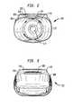
- FIG. 2is a frontal view of the lancing device of FIG. 1 ;
- FIG. 3is a rear view of the lancing device of FIG. 1 ;
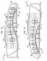
- FIG. 5is a second side view of the lancing device of FIG. 1 ;
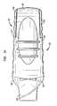
- FIG. 6is a top view of the lancing device of FIG. 1 ;
- FIG. 12is a second side view of-the lancing device of FIG. 8 ;
- FIG. 13is a top view of the lancing device of FIG. 8 ;
- FIG. 14is a bottom view of the lancing device of FIG. 8 ;
- FIG. 19is a frontal view of a first spring forming a portion of the lancing devices of the present invention.
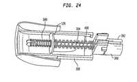
- FIG. 24is an internal view of a portion of the lancing device of FIG. 1 ;
- FIG. 28is a perspective view of a second step in the use of the lancing devices of the present invention.
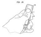
- FIG. 29is a perspective view of a third step in the use of the lancing devices of the present invention.
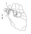
- FIG. 30is a perspective view of a fourth step in the use of the lancing devices of the present invention.
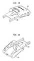
- the lancing device 100may include a main body 102 configured from an upper portion 104 , a lower portion 106 mated to the upper portion, and an actuator 108 .
- the lancet device 100may further include an endcap 110 mounted to the upper and lower portions 104 , 106 by endcap shoulders 112 .
- upper portion 104 and actuator 108are preferably configured to be of roughly the same length as the lower portion 106 . As will be appreciated when discussing use of the device, this enables the lower portion 106 to be retained in stationary relation with the palm of a user's hand while the actuator 108 is moved away from the endcap 110 and then toward the endcap.
- the endcap 110is an adjustable endcap, whereby rotation of the endcap to the various positions indicated by the sized blood drops 114 a - c (see FIG. 6 for full views) positions the distal end of endcap closer or further away from the main body 102 .
- the endcaplimits the excursion of a lancet placed within the lancing device such that the needle of the lancet penetrates the patient to a lesser degree than if the endcap were rotated toward the large blood drop, whereby the endcap would be positioned closest to the main body.
- the lancet device 100may also include an actuator button 116 disposed within the upper portion, depression of which is utilized to fire the lancet once the mechanism is cocked. Cocking of the device 100 may be achieved by first loading a lancet within the device, retracting the actuator 108 by pulling or pushing the actuator away from the upper portion 104 , and then allowing the actuator to move back to the position shown in FIG. 1 directly adjacent the upper portion. It will be appreciated that springs may be provided to resist or assist with such movements.
- lancing device 100Additional components of the lancing device 100 include a lancet 200 , shown in FIGS. 15 and 16 .
- Lancetssuch as lancet 200 are generally known in the art, and consists of a holder 202 and a needle 204 held within the holder.
- the needle 204is fixed relative to the holder 202 and includes a distal end 206 which extends beyond the limits of the holder 202 . It is this distal end 206 which is permitted to extend beyond the limits of the lancing device 100 , includes the point 208 , and penetrates the patient in use.
- Additional componentsinclude the pusher 300 shown in FIGS. 17 and 18 and the first spring 400 and second spring 500 , the first spring being shown in FIGS. 19 and 20 and the second spring being shown in FIGS. 21 and 22 .
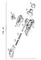
- the usermay rotate the device 100 within his palm (P) such that the actuator 108 faces away from the body, as shown in FIG. 28 . From this position, the user may easily move the actuator 108 from the position shown in FIG. 28 to the extended position shown in FIG. 29 , away from the endcap 110 . To aid in such movement, the actuator 108 may include a raised portion 109 . This serves to cock the lancet 200 for delivery, as previously discussed. It will also be appreciated that such procedure may readily be accomplished with one hand.
- One feature of the device 100 in this regardis that the device is sized and configured such that the forefinger (FF) of the user may rest upon the lower housing 106 , as shown in FIG. 28 . In this position, the lower housing 106 is stationary relative to the user's body and remainder of the main body 102 of the device as the actuator 106 is moved from the position of FIG. 28 to the extended position of FIG. 29 .
- FFforefinger
- the device 100may again be rotated back to the original position, as shown in FIG. 30 whereupon a user may use his thumb (T) to depress the actuation button 116 to fire the lancet 200 .
- This thumb
- the lancet 200is fired from the distal end of the endcap 110 , through the aperture 111 , and into the skin of a patient, which may or may not be the user.
- the endcap 110 and shoulders 112may be removed from the device 100 to expose the used lancet 200 , whereupon the lancet may be removed from the holder 302 and discarded.
- the holder 302may be constructed in a split configuration, as discussed above, such that the holder 302 may flex and retain the lancet in a frictional relation.
- the holder 302may include ramped portions 312 to aid in insertion, retention, and removal of the lancet 200 , the lancet 200 using the ramped portions 312 to force open the holder 302 .
Landscapes
- Health & Medical Sciences (AREA)
- Life Sciences & Earth Sciences (AREA)
- Engineering & Computer Science (AREA)
- Heart & Thoracic Surgery (AREA)
- Molecular Biology (AREA)
- Pathology (AREA)
- Physics & Mathematics (AREA)
- Biomedical Technology (AREA)
- Hematology (AREA)
- Medical Informatics (AREA)
- Biophysics (AREA)
- Surgery (AREA)
- Animal Behavior & Ethology (AREA)
- General Health & Medical Sciences (AREA)
- Public Health (AREA)
- Veterinary Medicine (AREA)
- Manufacturing & Machinery (AREA)
- Dermatology (AREA)
- Measurement Of The Respiration, Hearing Ability, Form, And Blood Characteristics Of Living Organisms (AREA)
Abstract
Description
Claims (15)
Priority Applications (1)
| Application Number | Priority Date | Filing Date | Title |
|---|---|---|---|
| US12/995,806US8828038B2 (en) | 2008-06-05 | 2008-12-04 | Lancing device |
Applications Claiming Priority (4)
| Application Number | Priority Date | Filing Date | Title |
|---|---|---|---|
| US29/308,253USD616987S1 (en) | 2008-06-05 | 2008-06-05 | Lancing device |
| US13113808P | 2008-06-06 | 2008-06-06 | |
| PCT/US2008/013505WO2009148431A1 (en) | 2008-06-05 | 2008-12-04 | Lancing device |
| US12/995,806US8828038B2 (en) | 2008-06-05 | 2008-12-04 | Lancing device |
Related Parent Applications (1)
| Application Number | Title | Priority Date | Filing Date |
|---|---|---|---|
| US29/308,253Continuation-In-PartUSD616987S1 (en) | 2008-06-05 | 2008-06-05 | Lancing device |
Publications (2)
| Publication Number | Publication Date |
|---|---|
| US20110184448A1 US20110184448A1 (en) | 2011-07-28 |
| US8828038B2true US8828038B2 (en) | 2014-09-09 |
Family
ID=44309530
Family Applications (1)
| Application Number | Title | Priority Date | Filing Date |
|---|---|---|---|
| US12/995,806Active2029-03-11US8828038B2 (en) | 2008-06-05 | 2008-12-04 | Lancing device |
Country Status (1)
| Country | Link |
|---|---|
| US (1) | US8828038B2 (en) |
Cited By (8)
| Publication number | Priority date | Publication date | Assignee | Title |
|---|---|---|---|---|
| USD740939S1 (en)* | 2014-04-23 | 2015-10-13 | Jerome Canady | Plasma scalpel handpiece |
| USD749732S1 (en)* | 2014-10-20 | 2016-02-16 | U.S. Medical Innovations LLS | Cold plasma handpiece |
| USD749733S1 (en)* | 2014-10-20 | 2016-02-16 | U.S. Patent Innovations Llc | Hybrid plasma handpiece |
| USD794790S1 (en)* | 2014-08-29 | 2017-08-15 | Sterilance Medical (Suzhou) Inc. | Disposable safety lancet |
| USD824517S1 (en) | 2017-01-19 | 2018-07-31 | Stephen A. Young | Blood sampling device |
| US10646150B2 (en) | 2013-03-12 | 2020-05-12 | Ascensia Diabetes Care Holdings Ag | Lancing device |
| USD910849S1 (en)* | 2019-05-08 | 2021-02-16 | Sterilance Medical (Suzhou) Inc. | Mini-type safety lancet |
| USD973876S1 (en) | 2020-03-18 | 2022-12-27 | Stephen A. Young | Blood sampling device |
Families Citing this family (26)
| Publication number | Priority date | Publication date | Assignee | Title |
|---|---|---|---|---|
| US8641644B2 (en) | 2000-11-21 | 2014-02-04 | Sanofi-Aventis Deutschland Gmbh | Blood testing apparatus having a rotatable cartridge with multiple lancing elements and testing means |
| US9427532B2 (en) | 2001-06-12 | 2016-08-30 | Sanofi-Aventis Deutschland Gmbh | Tissue penetration device |
| US9226699B2 (en) | 2002-04-19 | 2016-01-05 | Sanofi-Aventis Deutschland Gmbh | Body fluid sampling module with a continuous compression tissue interface surface |
| US9795747B2 (en) | 2010-06-02 | 2017-10-24 | Sanofi-Aventis Deutschland Gmbh | Methods and apparatus for lancet actuation |
| US7041068B2 (en) | 2001-06-12 | 2006-05-09 | Pelikan Technologies, Inc. | Sampling module device and method |
| US6966880B2 (en)* | 2001-10-16 | 2005-11-22 | Agilent Technologies, Inc. | Universal diagnostic platform |
| US9248267B2 (en) | 2002-04-19 | 2016-02-02 | Sanofi-Aventis Deustchland Gmbh | Tissue penetration device |
| US9795334B2 (en) | 2002-04-19 | 2017-10-24 | Sanofi-Aventis Deutschland Gmbh | Method and apparatus for penetrating tissue |
| US9314194B2 (en) | 2002-04-19 | 2016-04-19 | Sanofi-Aventis Deutschland Gmbh | Tissue penetration device |
| US8579831B2 (en) | 2002-04-19 | 2013-11-12 | Sanofi-Aventis Deutschland Gmbh | Method and apparatus for penetrating tissue |
| US8784335B2 (en) | 2002-04-19 | 2014-07-22 | Sanofi-Aventis Deutschland Gmbh | Body fluid sampling device with a capacitive sensor |
| US8702624B2 (en) | 2006-09-29 | 2014-04-22 | Sanofi-Aventis Deutschland Gmbh | Analyte measurement device with a single shot actuator |
| US7708701B2 (en) | 2002-04-19 | 2010-05-04 | Pelikan Technologies, Inc. | Method and apparatus for a multi-use body fluid sampling device |
| US20120296233A9 (en)* | 2002-09-05 | 2012-11-22 | Freeman Dominique M | Methods and apparatus for an analyte detecting device |
| US8574895B2 (en) | 2002-12-30 | 2013-11-05 | Sanofi-Aventis Deutschland Gmbh | Method and apparatus using optical techniques to measure analyte levels |
| WO2006001797A1 (en)* | 2004-06-14 | 2006-01-05 | Pelikan Technologies, Inc. | Low pain penetrating |
| US8282576B2 (en) | 2003-09-29 | 2012-10-09 | Sanofi-Aventis Deutschland Gmbh | Method and apparatus for an improved sample capture device |
| EP1680014A4 (en) | 2003-10-14 | 2009-01-21 | Pelikan Technologies Inc | METHOD AND DEVICE FOR A VARIABLE USER INTERFACE |
| US8668656B2 (en) | 2003-12-31 | 2014-03-11 | Sanofi-Aventis Deutschland Gmbh | Method and apparatus for improving fluidic flow and sample capture |
| WO2006011062A2 (en) | 2004-05-20 | 2006-02-02 | Albatros Technologies Gmbh & Co. Kg | Printable hydrogel for biosensors |
| WO2005120365A1 (en) | 2004-06-03 | 2005-12-22 | Pelikan Technologies, Inc. | Method and apparatus for a fluid sampling device |
| US9775553B2 (en) | 2004-06-03 | 2017-10-03 | Sanofi-Aventis Deutschland Gmbh | Method and apparatus for a fluid sampling device |
| US8956308B2 (en)* | 2008-09-29 | 2015-02-17 | Bayer Healthcare Llc | Integrated-testing system |
| US9375169B2 (en) | 2009-01-30 | 2016-06-28 | Sanofi-Aventis Deutschland Gmbh | Cam drive for managing disposable penetrating member actions with a single motor and motor and control system |
| US8965476B2 (en) | 2010-04-16 | 2015-02-24 | Sanofi-Aventis Deutschland Gmbh | Tissue penetration device |
| WO2014116688A1 (en) | 2013-01-23 | 2014-07-31 | Facet Technologies, Llc | Push-to-charge lancing device |
Citations (16)
| Publication number | Priority date | Publication date | Assignee | Title |
|---|---|---|---|---|
| USD342573S (en) | 1991-12-13 | 1993-12-21 | Ryder International Corporation | Lancet actuator |
| US5984940A (en) | 1997-05-29 | 1999-11-16 | Atrion Medical Products, Inc. | Lancet device |
| USD428150S (en) | 1999-02-23 | 2000-07-11 | Lifescan, Inc. | Lancing device |
| USD444557S1 (en) | 1999-10-19 | 2001-07-03 | Facet Technologies, Llc | Lancing device |
| US6749618B2 (en)* | 1999-10-19 | 2004-06-15 | Therasense, Inc. | Lancing device and method of sample collection |
| USD493532S1 (en) | 2002-12-19 | 2004-07-27 | Facet Technologies, Llc | Lancing device |
| WO2005077275A1 (en) | 2004-02-06 | 2005-08-25 | Bayer Healthcare Llc | Dampening and retraction mechanism for a lancing device |
| USD523555S1 (en) | 2003-05-02 | 2006-06-20 | Pelikan Technologies, Inc. | Lancing device user interface |
| USD531725S1 (en) | 2003-11-05 | 2006-11-07 | Pelikan Technolgies, Inc. | Lancing device |
| USD550363S1 (en) | 2005-03-05 | 2007-09-04 | Roche Diagnostics Operations, Inc. | Lancing device |
| US20070288047A1 (en) | 2003-08-07 | 2007-12-13 | Roche Diagnostics Operations, Inc. | Blood withdrawal system |
| USD560805S1 (en) | 2006-06-15 | 2008-01-29 | Abbott Diabetes Care Inc. | Lancing device |
| US20080058631A1 (en) | 2004-04-16 | 2008-03-06 | Draudt Gregg R | Blood glucose meter having integral lancet device and test strip storage vial for single handed use and methods for using same |
| USD569975S1 (en) | 2006-06-07 | 2008-05-27 | Becton Dickinson Co | Lancet device |
| USD586465S1 (en) | 2008-05-09 | 2009-02-10 | Lifescan Scotland Limited | Handheld lancing device |
| USD586916S1 (en) | 2008-05-09 | 2009-02-17 | Lifescan Scotland, Ltd. | Handheld lancing device |
- 2008
- 2008-12-04USUS12/995,806patent/US8828038B2/enactiveActive
Patent Citations (17)
| Publication number | Priority date | Publication date | Assignee | Title |
|---|---|---|---|---|
| USD342573S (en) | 1991-12-13 | 1993-12-21 | Ryder International Corporation | Lancet actuator |
| US5984940A (en) | 1997-05-29 | 1999-11-16 | Atrion Medical Products, Inc. | Lancet device |
| USD428150S (en) | 1999-02-23 | 2000-07-11 | Lifescan, Inc. | Lancing device |
| USD444557S1 (en) | 1999-10-19 | 2001-07-03 | Facet Technologies, Llc | Lancing device |
| US6749618B2 (en)* | 1999-10-19 | 2004-06-15 | Therasense, Inc. | Lancing device and method of sample collection |
| USD493532S1 (en) | 2002-12-19 | 2004-07-27 | Facet Technologies, Llc | Lancing device |
| USD523555S1 (en) | 2003-05-02 | 2006-06-20 | Pelikan Technologies, Inc. | Lancing device user interface |
| US20070288047A1 (en) | 2003-08-07 | 2007-12-13 | Roche Diagnostics Operations, Inc. | Blood withdrawal system |
| USD531725S1 (en) | 2003-11-05 | 2006-11-07 | Pelikan Technolgies, Inc. | Lancing device |
| WO2005077275A1 (en) | 2004-02-06 | 2005-08-25 | Bayer Healthcare Llc | Dampening and retraction mechanism for a lancing device |
| US20080039885A1 (en) | 2004-02-06 | 2008-02-14 | Purcell D Glenn | Dampening And Retraction Mechanism For A Lancing Device |
| US20080058631A1 (en) | 2004-04-16 | 2008-03-06 | Draudt Gregg R | Blood glucose meter having integral lancet device and test strip storage vial for single handed use and methods for using same |
| USD550363S1 (en) | 2005-03-05 | 2007-09-04 | Roche Diagnostics Operations, Inc. | Lancing device |
| USD569975S1 (en) | 2006-06-07 | 2008-05-27 | Becton Dickinson Co | Lancet device |
| USD560805S1 (en) | 2006-06-15 | 2008-01-29 | Abbott Diabetes Care Inc. | Lancing device |
| USD586465S1 (en) | 2008-05-09 | 2009-02-10 | Lifescan Scotland Limited | Handheld lancing device |
| USD586916S1 (en) | 2008-05-09 | 2009-02-17 | Lifescan Scotland, Ltd. | Handheld lancing device |
Non-Patent Citations (7)
| Title |
|---|
| English translation of the Decision of the Intellectual Property Office in Taiwan for Application No. 097147513 dated May 24, 2012. |
| International Search Report, PCT/US2008/013505, dated Feb. 9, 2009. |
| Taiwan Design Reference No. D123459 dated Jun. 21, 2008. |
| Taiwan Office Action and Search Report for Application 097147513 dated Nov. 9, 2011. |
| Taiwan Search Report for Application No. 097306925 dated Jan. 5, 2010. |
| Taiwan Utility Model No. TWM310692. |
| Taiwan Utility Model No. TWM310692-Translation. |
Cited By (9)
| Publication number | Priority date | Publication date | Assignee | Title |
|---|---|---|---|---|
| US10646150B2 (en) | 2013-03-12 | 2020-05-12 | Ascensia Diabetes Care Holdings Ag | Lancing device |
| US11672451B2 (en) | 2013-03-12 | 2023-06-13 | Ascensia Diabetes Care Holdings Ag | Lancing device |
| USD740939S1 (en)* | 2014-04-23 | 2015-10-13 | Jerome Canady | Plasma scalpel handpiece |
| USD794790S1 (en)* | 2014-08-29 | 2017-08-15 | Sterilance Medical (Suzhou) Inc. | Disposable safety lancet |
| USD749732S1 (en)* | 2014-10-20 | 2016-02-16 | U.S. Medical Innovations LLS | Cold plasma handpiece |
| USD749733S1 (en)* | 2014-10-20 | 2016-02-16 | U.S. Patent Innovations Llc | Hybrid plasma handpiece |
| USD824517S1 (en) | 2017-01-19 | 2018-07-31 | Stephen A. Young | Blood sampling device |
| USD910849S1 (en)* | 2019-05-08 | 2021-02-16 | Sterilance Medical (Suzhou) Inc. | Mini-type safety lancet |
| USD973876S1 (en) | 2020-03-18 | 2022-12-27 | Stephen A. Young | Blood sampling device |
Also Published As
| Publication number | Publication date |
|---|---|
| US20110184448A1 (en) | 2011-07-28 |
Similar Documents
| Publication | Publication Date | Title |
|---|---|---|
| US8828038B2 (en) | Lancing device | |
| US10842428B2 (en) | Contact activated lancet device | |
| EP1633249B1 (en) | Lancet device | |
| CN1981702B (en) | Analyte monitoring system with integrated lancing apparatus | |
| US8118825B2 (en) | Lancet device | |
| EP1755456B1 (en) | Contact activated lancet device | |
| US8858582B2 (en) | Push activation lancet device | |
| US20040015064A1 (en) | Blood sampling apparatus | |
| US9066688B2 (en) | Contact activated lancet device | |
| EP3616617B1 (en) | Lancet device with first-drop removal | |
| EP2263540B1 (en) | Contact activated lancet device | |
| CN102613977A (en) | Cam-actuated medical puncturing device and method | |
| WO2009148431A1 (en) | Lancing device | |
| EP2653099B1 (en) | Lancet device capable of lancet detachment | |
| WO2025019736A1 (en) | Biopsy device arming mechanism | |
| AU2012202665B2 (en) | Contact activated lancet device |
Legal Events
| Date | Code | Title | Description |
|---|---|---|---|
| AS | Assignment | Owner name:BAYER HEALTHCARE LLC, NEW YORK Free format text:ASSIGNMENT OF ASSIGNORS INTEREST;ASSIGNORS:BROWN, DANIEL;MATHELIER, MARTIN ANTOINE;LORZA, MARIA ISABEL;AND OTHERS;SIGNING DATES FROM 20081021 TO 20081103;REEL/FRAME:026101/0897 | |
| AS | Assignment | Owner name:BAYER HEALTHCARE LLC, NEW YORK Free format text:CORRECTIVE ASSIGNMENT TO CORRECT THE ADDRESS OF RECELVING PARTY PREVIOUSLY RECORDED ON REEL 026101, FRAME 0697;ASSIGNORS:BROWN, DANIEL;MATHELIER, MARTIN ANTOINE;LORZA, MARIA ISABEL;AND OTHERS;SIGNING DATES FROM 20081021 TO 20081030;REEL/FRAME:027677/0001 Owner name:BAYER HEALTHCARE LLC, NEW YORK Free format text:CORRECTIVE ASSIGNMENT TO CORRECT THE ADDRESS OF RECELVING PARTY PREVIOUSLY RECORDED ON REEL 026101, FRAME 0697;ASSIGNORS:BROWN, DANIEL;MATHELIER, MARTIN ANTOINE;LORZA, MARIA ISABEL;AND OTHERS;SIGNING DATES FROM 20081021 TO 20081103;REEL/FRAME:027677/0001 | |
| FEPP | Fee payment procedure | Free format text:PAYOR NUMBER ASSIGNED (ORIGINAL EVENT CODE: ASPN); ENTITY STATUS OF PATENT OWNER: LARGE ENTITY | |
| STCF | Information on status: patent grant | Free format text:PATENTED CASE | |
| CC | Certificate of correction | ||
| CC | Certificate of correction | ||
| AS | Assignment | Owner name:ASCENSIA DIABETES CARE HOLDING AG, SWITZERLAND Free format text:ASSIGNMENT OF ASSIGNORS INTEREST;ASSIGNOR:BAYER HEALTHCARE LLC;REEL/FRAME:038009/0420 Effective date:20160104 | |
| MAFP | Maintenance fee payment | Free format text:PAYMENT OF MAINTENANCE FEE, 4TH YEAR, LARGE ENTITY (ORIGINAL EVENT CODE: M1551) Year of fee payment:4 | |
| MAFP | Maintenance fee payment | Free format text:PAYMENT OF MAINTENANCE FEE, 8TH YEAR, LARGE ENTITY (ORIGINAL EVENT CODE: M1552); ENTITY STATUS OF PATENT OWNER: LARGE ENTITY Year of fee payment:8 |