US8828003B2 - Minimally invasive bone miller apparatus - Google Patents
Minimally invasive bone miller apparatusDownload PDFInfo
- Publication number
- US8828003B2 US8828003B2US13/432,040US201213432040AUS8828003B2US 8828003 B2US8828003 B2US 8828003B2US 201213432040 AUS201213432040 AUS 201213432040AUS 8828003 B2US8828003 B2US 8828003B2
- Authority
- US
- United States
- Prior art keywords
- cutter
- frame
- gear
- handle
- miller
- Prior art date
- Legal status (The legal status is an assumption and is not a legal conclusion. Google has not performed a legal analysis and makes no representation as to the accuracy of the status listed.)
- Active, expires
Links
- 210000000988bone and boneAnatomy0.000titleclaimsabstractdescription29
- 238000000034methodMethods0.000claimsabstractdescription17
- 210000000689upper legAnatomy0.000claimsabstractdescription13
- 230000008878couplingEffects0.000claimsabstractdescription9
- 238000010168coupling processMethods0.000claimsabstractdescription9
- 238000005859coupling reactionMethods0.000claimsabstractdescription9
- 238000003801millingMethods0.000claimsabstractdescription7
- 230000007246mechanismEffects0.000claimsdescription11
- 238000002360preparation methodMethods0.000description8
- 229920003023plasticPolymers0.000description4
- 239000004033plasticSubstances0.000description4
- 239000007943implantSubstances0.000description3
- 238000002513implantationMethods0.000description3
- 238000003754machiningMethods0.000description3
- 229910052751metalInorganic materials0.000description3
- 239000002184metalSubstances0.000description3
- 208000010392Bone FracturesDiseases0.000description2
- 206010017076FractureDiseases0.000description2
- 230000001154acute effectEffects0.000description2
- 238000011882arthroplastyMethods0.000description2
- 238000005553drillingMethods0.000description2
- 210000003739neckAnatomy0.000description2
- 210000004872soft tissueAnatomy0.000description2
- 239000010935stainless steelSubstances0.000description2
- 229910001220stainless steelInorganic materials0.000description2
- 238000001356surgical procedureMethods0.000description2
- 229920005123Celcon®Polymers0.000description1
- 229910000684Cobalt-chromeInorganic materials0.000description1
- 229920004142LEXAN™Polymers0.000description1
- 229920003295Radel®Polymers0.000description1
- RTAQQCXQSZGOHL-UHFFFAOYSA-NTitaniumChemical compound[Ti]RTAQQCXQSZGOHL-UHFFFAOYSA-N0.000description1
- 229920003997Torlon®Polymers0.000description1
- 229920004738ULTEM®Polymers0.000description1
- 230000000712assemblyEffects0.000description1
- 238000000429assemblyMethods0.000description1
- 239000010952cobalt-chromeSubstances0.000description1
- 239000002537cosmeticSubstances0.000description1
- 238000011161developmentMethods0.000description1
- 238000011540hip replacementMethods0.000description1
- 238000003780insertionMethods0.000description1
- 230000037431insertionEffects0.000description1
- 210000003127kneeAnatomy0.000description1
- 230000007774longtermEffects0.000description1
- 230000013011matingEffects0.000description1
- 238000002324minimally invasive surgeryMethods0.000description1
- 230000000399orthopedic effectEffects0.000description1
- 229920000515polycarbonatePolymers0.000description1
- 239000004417polycarbonateSubstances0.000description1
- 238000011160researchMethods0.000description1
- 239000010936titaniumSubstances0.000description1
- 229910052719titaniumInorganic materials0.000description1
- 238000011541total hip replacementMethods0.000description1
Images


Classifications
- A—HUMAN NECESSITIES
- A61—MEDICAL OR VETERINARY SCIENCE; HYGIENE
- A61B—DIAGNOSIS; SURGERY; IDENTIFICATION
- A61B17/00—Surgical instruments, devices or methods
- A61B17/16—Instruments for performing osteoclasis; Drills or chisels for bones; Trepans
- A61B17/1662—Instruments for performing osteoclasis; Drills or chisels for bones; Trepans for particular parts of the body
- A61B17/1664—Instruments for performing osteoclasis; Drills or chisels for bones; Trepans for particular parts of the body for the hip
- A61B17/1668—Instruments for performing osteoclasis; Drills or chisels for bones; Trepans for particular parts of the body for the hip for the upper femur
- A—HUMAN NECESSITIES
- A61—MEDICAL OR VETERINARY SCIENCE; HYGIENE
- A61B—DIAGNOSIS; SURGERY; IDENTIFICATION
- A61B17/00—Surgical instruments, devices or methods
- A61B17/16—Instruments for performing osteoclasis; Drills or chisels for bones; Trepans
- A61B17/17—Guides or aligning means for drills, mills, pins or wires
- A61B17/1739—Guides or aligning means for drills, mills, pins or wires specially adapted for particular parts of the body
- A61B17/1742—Guides or aligning means for drills, mills, pins or wires specially adapted for particular parts of the body for the hip
- A61B17/175—Guides or aligning means for drills, mills, pins or wires specially adapted for particular parts of the body for the hip for preparing the femur for hip prosthesis insertion
- A—HUMAN NECESSITIES
- A61—MEDICAL OR VETERINARY SCIENCE; HYGIENE
- A61B—DIAGNOSIS; SURGERY; IDENTIFICATION
- A61B17/00—Surgical instruments, devices or methods
- A61B17/16—Instruments for performing osteoclasis; Drills or chisels for bones; Trepans
- A61B17/1662—Instruments for performing osteoclasis; Drills or chisels for bones; Trepans for particular parts of the body
- A61B17/1675—Instruments for performing osteoclasis; Drills or chisels for bones; Trepans for particular parts of the body for the knee
- A—HUMAN NECESSITIES
- A61—MEDICAL OR VETERINARY SCIENCE; HYGIENE
- A61B—DIAGNOSIS; SURGERY; IDENTIFICATION
- A61B17/00—Surgical instruments, devices or methods
- A61B17/16—Instruments for performing osteoclasis; Drills or chisels for bones; Trepans
- A61B17/1662—Instruments for performing osteoclasis; Drills or chisels for bones; Trepans for particular parts of the body
- A61B17/1684—Instruments for performing osteoclasis; Drills or chisels for bones; Trepans for particular parts of the body for the shoulder
- A—HUMAN NECESSITIES
- A61—MEDICAL OR VETERINARY SCIENCE; HYGIENE
- A61F—FILTERS IMPLANTABLE INTO BLOOD VESSELS; PROSTHESES; DEVICES PROVIDING PATENCY TO, OR PREVENTING COLLAPSING OF, TUBULAR STRUCTURES OF THE BODY, e.g. STENTS; ORTHOPAEDIC, NURSING OR CONTRACEPTIVE DEVICES; FOMENTATION; TREATMENT OR PROTECTION OF EYES OR EARS; BANDAGES, DRESSINGS OR ABSORBENT PADS; FIRST-AID KITS
- A61F2/00—Filters implantable into blood vessels; Prostheses, i.e. artificial substitutes or replacements for parts of the body; Appliances for connecting them with the body; Devices providing patency to, or preventing collapsing of, tubular structures of the body, e.g. stents
- A61F2/02—Prostheses implantable into the body
- A61F2/30—Joints
- A61F2/32—Joints for the hip
- A61F2/36—Femoral heads ; Femoral endoprostheses
- A61F2/3662—Femoral shafts
- A61F2/367—Proximal or metaphyseal parts of shafts
Definitions
- This inventionrelates to the field of artificial joint prostheses and, in particular, to an improved instrument for machining a precise cavity in bone for receiving a prosthesis.
- the bone canalis presently prepared for implantation of a prosthetic stem by drilling and reaming a resected end of a bone, such as a femur, and then preparing an area adjacent the drilled hole to provide a seat for the prosthetic stem or a proximal sleeve coupled to the stem of a modular prosthetic system.
- Modular prosthetic systems using proximal sleeves, stems, necks and headssuch as the S-ROM Modular Hip System, available from DePuy Orthopaedics, Warsaw, Ind., put more control in the hands of the surgeon, providing solutions for a variety of surgical scenarios, from primary total hip arthroplasty (THA) to the complex revision or DDH challenges.
- THAprimary total hip arthroplasty
- Such systemprovides such versatility because the provided plurality of stems, sleeves, necks and heads which can be assembled in a large number of configurations.
- Preparation of the area adjacent the drilled holemay be accomplished by broaching or by milling.
- Broaches or raspswhen used for bone preparation, have limitations. One such limitation is the risk of fracture during broaching. Since broaching is done by pounding the broach into the bone, the bone tends to fracture. Additionally, both broaches and rasps suffer from a tendency to be deflected by harder sections of bone so that they do not create as precise a triangular cavity as can be created by a miller system.
- Paul et al.found that broaching tore the trabecular bone, whereas femoral canal preparation with reamers was consistently more accurate. Paul, H. A., et al. “Development of a Surgical Robot for Cementless Total Hip Arthroplasty.” Clinical Orthopedics and Related Research 285 December 1992: 57-66.
- millingis currently the preferred method of bone preparation in many orthopaedic applications because it is an extremely precise method of bone preparation.
- a limitation of milling systems todayis that they are typically formed so that the drive shaft extends at an angle relative to the remainder of the frame from the end of the miller cutter machining the bone.
- a fairly large incisionmust be made to accommodate such milling assemblies.
- a typical incision for preparing a femur for a total prosthetic hip replacement using a standard triangle miller systemis eight to ten inches long. It is not uncommon for incisions as large as 12 inches to be used in a total hip replacement procedure.
- a standard triangle miller systemtypically includes a miller shell, a miller frame and a miller cutter having an end formed for coupling to a drill.
- a typical miller frame and miller cuttercan be seen in U.S. Pat. No. 5,540,694 issued to DeCarlo, Jr. et al. on Jul. 30, 1996.
- This miller frameallows for precise machining of the triangular canal by a miller cutter held at an angle with respect to the shaft of the frame.
- the triangular canalfacilitates an accurate fit of a proximal sleeve that distributes the load experienced by the prosthesis evenly and provides rotational stability.
- it is necessary to make a fairly large incisionwhich may be undesirable for cosmetic or other reasons.
- the miller cutterincludes a fixed input shaft for connecting to and/or receiving motive (i.e. rotary) power from a drill or similar instrument.
- motivei.e. rotary
- the prior reameris able to accept rotary input power with respect to only one direction.
- this directionis at 0° (i.e. “straight on”) with respect to the reamer which is approximately thirty two degrees with respect to the shaft of the miller frame. Therefore, not only is the input power direction restricted, but this, in turn, restricts the angle at which the reamer may be used on a patient.
- an incision substantially larger than the width of the framemust be made to accommodate the reamer, frame and drill during surgery.
- the incisionmust be large enough to accommodate the reamer, frame, input shaft and drill without the input shaft engaging soft tissue.
- a miller assemblyfor creating a cavity in a bone.
- the cavityhas a cross section which has a generally triangular profile having a first side generally parallel with an axis of the bone and a second side forming an acute angle with the first side, and is contiguous with a pre-existing conical cavity in the bone.
- the assemblyincludes a cutter and a frame for carrying the cutter.
- the frameincludes a connection portion having a longitudinal axis and a cutter mount for mounting the cutter at a first angle approximating the acute angle with respect to the longitudinal axis of the connection portion.
- the cutter mountextends at the first angle from the longitudinal axis of the connection portion and is configured to receive a portion of the cutter and maintain the received cutter oriented at the first angle during rotation.
- the framefurther includes a handle configured to form a portion of a drive joint for coupling the frame to a drill, the handle having a longitudinal axis. The longitudinal axis of the handle is coincident with the longitudinal axis of the frame.
- a miller assemblyfor creating a cavity in a bone.
- the systemincludes a cutter and a frame for carrying the cutter.
- the framehas a longitudinal axis and a cutter mount for mounting the cutter at a first angle with respect to the longitudinal axis of the frame.
- the cutter mountextends at the first angle from the longitudinal axis of the frame and is configured to receive a portion of the cutter and to maintain the received cutter oriented at the first angle during rotation.
- the framefurther includes a handle configured to form a portion of a drive joint for coupling the frame to a drill having a longitudinal axis.
- the handlehas a longitudinal axis, such that the longitudinal axis of the handle is coincident with the longitudinal axis of the frame.
- the cutteris coupled to the connection portion and handle such that when the drill is activated, the cutter rotates.
- a method of milling a calcar region of the femurincluding providing a miller assembly including a cutter and a frame for carrying the cutter.
- the framehas a longitudinal axis and a cutter mount for mounting the cutter at a first angle with respect to the longitudinal axis of the frame.
- the cutter mountextends at the first angle from the longitudinal axis of the frame and is configured to receive a portion of the cutter and to maintain the received cutter oriented at the first angle during rotation.
- the framefurther includes a handle configured to form a portion of a drive joint for coupling the frame to a drill, the handle having a longitudinal axis.
- the handleis coupled to the drill.
- the miller assemblyis inserted into the femur such that the cutter is located in the calcar region.
- the drillis then operated, causing the cutter to rotate and mill bone in the calcar region
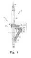
- FIG. 1is a perspective view of a miller system according to one embodiment of the present invention
- FIG. 2is an exploded view of the miller system of FIG. 1 ;
- FIG. 3is a perspective view of the miller frame of FIG. 1 illustrating the mating of the gears
- FIG. 4is a perspective view with parts broken away of the miller system of FIG. 1 inserted into a resected femur of a patient;
- FIG. 5is a flow chart describing a method of using the miller of FIG. 1 ;
- FIG. 6is a perspective view of a miller system according to another embodiment of the present invention.
- the disclosed calcar miller assembly 10allows a surgeon to machine (mill) bone through a smaller incision compared to existing surgical instruments.
- the miller assembly 10includes a frame 12 and a miller cutter 14 that is coupled to the frame 12 at both a proximal end 16 and a distal end 18 .
- the frame 12includes a longitudinal axis 20 .
- the miller cutter 14also has a longitudinal axis 22 that is offset at an angle ⁇ from the longitudinal axis 20 of the frame 12 .
- the angle ⁇is greater than 0 degrees. In some embodiments, the angle ⁇ is between about 30 and about 60 degrees. In some embodiments, the angle ⁇ is between about 40 degrees and about 50 degrees.
- FIG. 2an exploded view of the calcar miller assembly 10 of FIG. 1 is illustrated.
- the frame 12includes three parts: a handle 24 , a connection portion 26 , and a pilot shaft 28 .
- the handle 24includes a drill-connection end 30 and a connection-portion end 32 .
- the drill-connection end 30includes a drill-connection feature 34 adapted to connect the handle to a drill (not shown), creating a drive joint. The drill will drive the miller cutter 14 .
- the handle 24also becomes the drive shaft, such that the longitudinal axis of the handle is coincident with the longitudinal axis of the drive shaft.
- connection-portion end 32 of the handle 24includes a gear 36 that will couple with a gear 38 of the connection portion 26 , as will be described in more detail below.
- the connection-portion end 32 of the handle 24also includes a rod 40 , for connecting the handle 24 to the connection portion 26 .
- the rod 40includes a locking mechanism 42 that corresponds to a locking mechanism 44 (shown in phantom) on the connection portion 26 .
- the rod and connection portion locking mechanisms 42 , 44may include a recess on one and an internal ridge on the other. Other locking mechanisms, including, but not limited to, threads, tapers, locking bulbs, and locking tabs, may be used. Also, the pieces may be welded together.
- the rod 40may be located on the connection portion 26 .
- the rod 40would engage a cavity in the handle 24 .
- the connection portion 26includes a handle-connection end 46 and a shaft-connection end 48 .
- the handle-connection end 46couples to the handle 24 as described above.
- the handle-connection end 46includes an outwardly extending flange 50 .
- the flange 50includes a recess 52 for receiving the gear 38 .
- the gear 38couples to a lower gear 54 via a thread 56 on the gear 38 that matingly engages an internal thread 58 (as shown in phantom) on the lower gear 54 .
- the miller cutter 14slides onto a cutter mount, or an outwardly extending pole 60 .
- the pole 60extends at the desired angle ⁇ as described and shown above in reference to FIG. 1 .
- the outwardly extending pole 60includes a locking mechanism 62 , which in the illustrated embodiment, is a nut 62 a ( FIG. 1 ) and a threads 62 b on the pole 60 .
- a locking mechanism 62which in the illustrated embodiment, is a nut 62 a ( FIG. 1 ) and a threads 62 b on the pole 60 .
- other locking mechanismssuch as taper locks, locking bulbs, locking tabs and other known locking mechanisms may be used.
- the miller cutter 14also includes a gear 63 that will mate with the lower gear 54 . Also, the pieces may be welded together.
- the shaft-connection end 48 of the connection portion 26includes a locking mechanism 64 for locking the connection portion 26 to the shaft 28 .
- the locking mechanism 64includes a recess 66 which will engage an internal ridge 68 (shown in FIG. 3 ) on the shaft 28 .
- Other locking mechanismsincluding, but not limited to, threads, tapers, locking bulbs, and locking tabs, may be used. In other embodiments, the pieces may be welded together.
- the shaft 28will be connected to a miller shell (not shown).
- the handle 24 and connection portion 26will slide into the miller shell.
- the handle 24 /connection portion 26can be moved up and down relative to the miller shell in order to adjust the depth of the drilling.
- a shroud 69is shown in phantom.
- the shroud 69may be included to cover the gears 36 , 38 , 54 , 63 .
- the shroud 69would be to protect the gears 36 , 38 , 54 , 63 during the surgery. Also, the shroud 69 could keep the gears 36 , 38 , 54 , 63 from engaging the bone and/or soft tissue.
- FIG. 4a perspective view of the connection portion 26 with the miller cutter 14 placed on the pole 60 is shown.
- the connection portion 26is shown in a femur 70 , with the miller cutter 14 located in the calcar region 72 .
- the handle gear 36will rotate with the handle 24 .
- the handle gear 36will engage the top connection portion gear 38 to rotate, causing the bottom connection gear 54 to rotate.
- the bottom connection gear 54is engaged with the miller cutter gear 63 such that when the bottom connection gear 54 rotates, so does the miller cutter gear 63 .
- the resultis that the calcar region 72 is milled in preparation for receiving an implant.
- step s 100the miller will be inserted into the femur 70 , with the miller cutter 14 being inserted into the calcar region 72 .
- the drillcauses the handle 24 and handle gear 36 rotate.
- the rotation of the handle gear 36causes the lower gear 54 to rotate (step s 104 ), which in turn drives the rotation of the miller cutter 14 (step s 106 ).
- the miller cutter 14then mills the bone in the calcar region 72 of the femur 70 , preparing the calcar region for the insertion of the implant.
- the miller 10can be inserted into a miller shell (not shown).
- the miller shellis inserted into the femur and the miller 10 can be adjusted vertically so as to adjust the cutting depth.
- FIG. 6a second embodiment of the present invention is illustrated.
- the handle 24 of the miller assembly 10is coupled to the connection portion 26 via a belt 74 .
- the belt 74winds around a cylinder 76 located on the handle 24 and a cylinder 78 on the flange 50 .
- the cylinder 78 on the flangeis coupled to the bottom connection gear 54 in the same way that the top connection gear 38 is coupled to the bottom connection gear 54 in the above-described embodiment.
- the handle 24is rotated, the cylinder 76 rotates, causing the belt 74 to move.
- the movement of the belt 74then causes the cylinder 78 of the flange to rotate, rotating the upper gear 38 and bottom connection gear 54 .
- the bottom connection gear 54then couples with the cutter gear 63 .
- the miller cutter assembly 10is made of stainless steel or other biocompatible metal, such as titanium or cobalt chrome. Any other sterilizable metal may be used.
- the handle 24 , connection portion 26 , and pilot shaftmay be disposable and made of a biocompatible plastic such as polycarbonate, LEXAN®, ULTEM®, both manufactured by Sabic Innovation Plastics of Houston, Tex., CELCON®, manufactured by Ticona of Florence, Ky., UDEL®, RADEL®, ACUDEL®, MINDEL®, Epispire, Primospire, TORLON®, all manufactured by Solvay Plastics of Brussels, or any other biocompatible plastic, while the miller cutter 14 is made of stainless steel or other sterilizable metal.
- the width of the deviceis less than about 2 and one half inches, and in some embodiments, less than about 2 inches.
- the frame 12was in three parts.
- the framemay be a single piece or may have more or less than three parts.
Landscapes
- Health & Medical Sciences (AREA)
- Surgery (AREA)
- Life Sciences & Earth Sciences (AREA)
- Biomedical Technology (AREA)
- Medical Informatics (AREA)
- Orthopedic Medicine & Surgery (AREA)
- Oral & Maxillofacial Surgery (AREA)
- Engineering & Computer Science (AREA)
- Dentistry (AREA)
- Heart & Thoracic Surgery (AREA)
- Nuclear Medicine, Radiotherapy & Molecular Imaging (AREA)
- Molecular Biology (AREA)
- Animal Behavior & Ethology (AREA)
- General Health & Medical Sciences (AREA)
- Public Health (AREA)
- Veterinary Medicine (AREA)
- Surgical Instruments (AREA)
- Prostheses (AREA)
Abstract
Description
Claims (7)
Priority Applications (1)
| Application Number | Priority Date | Filing Date | Title |
|---|---|---|---|
| US13/432,040US8828003B2 (en) | 2008-09-30 | 2012-03-28 | Minimally invasive bone miller apparatus |
Applications Claiming Priority (2)
| Application Number | Priority Date | Filing Date | Title |
|---|---|---|---|
| US12/241,418US8167882B2 (en) | 2008-09-30 | 2008-09-30 | Minimally invasive bone miller apparatus |
| US13/432,040US8828003B2 (en) | 2008-09-30 | 2012-03-28 | Minimally invasive bone miller apparatus |
Related Parent Applications (1)
| Application Number | Title | Priority Date | Filing Date |
|---|---|---|---|
| US12/241,418DivisionUS8167882B2 (en) | 2008-09-30 | 2008-09-30 | Minimally invasive bone miller apparatus |
Publications (2)
| Publication Number | Publication Date |
|---|---|
| US20120226281A1 US20120226281A1 (en) | 2012-09-06 |
| US8828003B2true US8828003B2 (en) | 2014-09-09 |
Family
ID=41426394
Family Applications (2)
| Application Number | Title | Priority Date | Filing Date |
|---|---|---|---|
| US12/241,418Active2030-12-05US8167882B2 (en) | 2008-09-30 | 2008-09-30 | Minimally invasive bone miller apparatus |
| US13/432,040Active2029-01-14US8828003B2 (en) | 2008-09-30 | 2012-03-28 | Minimally invasive bone miller apparatus |
Family Applications Before (1)
| Application Number | Title | Priority Date | Filing Date |
|---|---|---|---|
| US12/241,418Active2030-12-05US8167882B2 (en) | 2008-09-30 | 2008-09-30 | Minimally invasive bone miller apparatus |
Country Status (3)
| Country | Link |
|---|---|
| US (2) | US8167882B2 (en) |
| EP (1) | EP2168506B1 (en) |
| AT (1) | ATE533415T1 (en) |
Cited By (1)
| Publication number | Priority date | Publication date | Assignee | Title |
|---|---|---|---|---|
| US11559405B2 (en) | 2020-02-12 | 2023-01-24 | Howmedica Osteonics Corp. | Robotic shoulder fracture management |
Families Citing this family (9)
| Publication number | Priority date | Publication date | Assignee | Title |
|---|---|---|---|---|
| USD622851S1 (en)* | 2009-12-08 | 2010-08-31 | Horton Kenneth L | Spinous process reamer |
| US20120089146A1 (en) | 2010-10-06 | 2012-04-12 | Howmedica Osteonics Corp. | System and method of bone preparation |
| EP2787901B1 (en)* | 2011-12-09 | 2017-06-07 | Howmedica Osteonics Corp. | Surgical reaming instrument for shaping a bone cavity |
| WO2013102089A1 (en) | 2011-12-30 | 2013-07-04 | Howmedica Osteonics Corp. | Systems for preparing bone voids to receive a prosthesis |
| US9610084B2 (en) | 2012-09-12 | 2017-04-04 | Peter Michael Sutherland Walker | Method and apparatus for hip replacements |
| US9526513B2 (en) | 2013-03-13 | 2016-12-27 | Howmedica Osteonics Corp. | Void filling joint prosthesis and associated instruments |
| US8713399B1 (en)* | 2013-10-10 | 2014-04-29 | Antcor S.A. | Reconfigurable barrel shifter and rotator |
| US10149763B2 (en) | 2015-01-12 | 2018-12-11 | Howmedica Osteonics Corp. | Multipurpose void filling prosthesis |
| EP4349282A3 (en)* | 2016-07-08 | 2024-10-09 | Biomet Manufacturing, LLC | Reamer and guide for glenoid augment preparation |
Citations (176)
| Publication number | Priority date | Publication date | Assignee | Title |
|---|---|---|---|---|
| US650795A (en) | 1900-01-17 | 1900-05-29 | William T Maxwell | Boring implement. |
| US1029402A (en) | 1911-04-11 | 1912-06-11 | Richard H Ritter | Milling attachment for drill-presses. |
| US3177507A (en) | 1962-05-24 | 1965-04-13 | Buell Ind Inc | Bolt pointer |
| US3633583A (en) | 1969-08-22 | 1972-01-11 | Meyer Fishbein | Orthopedic single-blade bone cutter |
| US3810312A (en) | 1971-11-11 | 1974-05-14 | Const Supply Co | Alignment instrument |
| US4004581A (en) | 1974-09-11 | 1977-01-25 | Friedrichsfeld Gmbh | Tool for forming a bed in a hip bone to receive an artificial acetabulum |
| US4116200A (en) | 1975-10-01 | 1978-09-26 | Aesculap-Werke Aktiengesellschaft Vormals Jetter & Scheerer | Milling tool for surgical purposes |
| US4473070A (en) | 1983-01-05 | 1984-09-25 | Regents Of The University Of Michigan | Intramedullary reamer |
| US4601289A (en) | 1985-04-02 | 1986-07-22 | Dow Corning Wright | Femoral trial prosthesis/rasp assembly |
| US4658808A (en) | 1984-05-11 | 1987-04-21 | Waldemar Link Gmbh & Co. | Arrangement for preparing an anatomically measured endoprosthesis |
| DE3538654A1 (en) | 1985-10-28 | 1987-04-30 | Mecron Med Prod Gmbh | DRILLING SYSTEM CONTAINING A DRILL GUIDE FOR THE INSERTION OF AN ENDOPROTHESIS AND RELATED PROSTHESIS |
| US4716894A (en) | 1986-08-27 | 1988-01-05 | Zimmer, Inc. | Acetabular cup inserting instrument |
| US4738256A (en) | 1985-06-26 | 1988-04-19 | Finsbury (Instruments) Limited | Surgical tool |
| US4777942A (en) | 1986-10-02 | 1988-10-18 | Sulzer Brothers Limited | Bone milling instrument |
| US4917530A (en) | 1989-08-31 | 1990-04-17 | Boehringer Mannheim Corporation | Structural joint |
| US4969911A (en) | 1989-02-17 | 1990-11-13 | United States Manufacturing Company | Adjustable prosthetic joint with alignment means |
| US5002578A (en) | 1990-05-04 | 1991-03-26 | Venus Corporation | Modular hip stem prosthesis apparatus and method |
| US5002581A (en) | 1989-11-03 | 1991-03-26 | Dow Corning Wright Corporation | Modular hip joint prosthesis with adjustable anteversion |
| US5015255A (en) | 1989-05-10 | 1991-05-14 | Spine-Tech, Inc. | Spinal stabilization method |
| WO1991010408A1 (en) | 1990-01-08 | 1991-07-25 | Zimmer, Inc. | Methods and apparatus for arthroscopic prosthetic knee replacement |
| US5047033A (en) | 1989-02-08 | 1991-09-10 | Smith & Nephew Richards Inc. | Mill and guide apparatus for preparation of a hip prosthesis |
| US5053037A (en) | 1991-03-07 | 1991-10-01 | Smith & Nephew Richards Inc. | Femoral instrumentation for long stem surgery |
| US5100407A (en) | 1990-09-04 | 1992-03-31 | Pfizer Hospital Products Group, Inc. | Modular trial hip replacement system |
| GB2250441A (en) | 1990-12-06 | 1992-06-10 | Jayantilal Mohanial Meswania | Surgical bone shaping instrument |
| US5135529A (en) | 1989-11-03 | 1992-08-04 | Dow Corning Wright Corporation | Instrument for implanting modular hip joint prosthesis with adjustable anteversion and method of using said instrument |
| US5169401A (en) | 1991-12-20 | 1992-12-08 | Zimmer, Inc. | Surgical reamer assembly |
| WO1993001769A1 (en) | 1991-07-23 | 1993-02-04 | Aktiebolaget Astra | Hip joint prosthesis |
| US5192283A (en) | 1990-08-10 | 1993-03-09 | Ling Robin S M | System for performing hip prosthesis revision surgery |
| US5197989A (en) | 1987-09-03 | 1993-03-30 | Hinckfuss Bruce W | Two stage joint prosthesis |
| US5201882A (en) | 1989-11-03 | 1993-04-13 | Paxson Robert D | Modular hip joint prosthesis with adjustable anteversion |
| US5207680A (en) | 1992-05-11 | 1993-05-04 | Zimmer, Inc. | Front milling guide for use in orthopaedic surgery |
| USD346979S (en) | 1993-02-11 | 1994-05-17 | Zimmer, Inc. | Bone milling template |
| WO1994012123A1 (en) | 1992-11-20 | 1994-06-09 | Burke Dennis W | Improved femoral implant collar and installation apparatus |
| US5336226A (en) | 1992-08-11 | 1994-08-09 | Chapman Lake Instruments, Inc. | Bone face cutter |
| US5342363A (en) | 1992-11-30 | 1994-08-30 | Wright Medical Technology, Inc. | Medical instrument and procedure |
| US5344423A (en) | 1992-02-06 | 1994-09-06 | Zimmer, Inc. | Apparatus and method for milling bone |
| US5370706A (en) | 1986-08-15 | 1994-12-06 | Depuy Inc. | Modular hip prosthesis |
| WO1994027507A1 (en) | 1993-05-27 | 1994-12-08 | Howmedica Inc. | Flexible medullary reaming system |
| US5372209A (en) | 1992-07-28 | 1994-12-13 | Dcd, Ltd. | Polycentric reamer |
| US5403320A (en) | 1993-01-07 | 1995-04-04 | Venus Corporation | Bone milling guide apparatus and method |
| USD357315S (en) | 1993-03-15 | 1995-04-11 | Zimmer, Inc. | Bone milling template |
| US5415659A (en) | 1993-12-01 | 1995-05-16 | Amei Technologies Inc. | Spinal fixation system and pedicle clamp |
| US5468243A (en) | 1993-10-27 | 1995-11-21 | Halpern; Alan A. | Femoral superior neck remodelling means and method |
| US5474559A (en) | 1993-07-06 | 1995-12-12 | Zimmer, Inc. | Femoral milling instrumentation for use in total knee arthroplasty with optional cutting guide attachment |
| US5496324A (en) | 1994-06-20 | 1996-03-05 | Zimmer, Inc. | Proximal body milling apparatus |
| US5507824A (en) | 1993-02-23 | 1996-04-16 | Lennox; Dennis W. | Adjustable prosthetic socket component, for articulating anatomical joints |
| US5507830A (en) | 1989-02-08 | 1996-04-16 | Smith & Nephew Richards Inc. | Modular hip prosthesis |
| US5507833A (en) | 1992-02-10 | 1996-04-16 | Kim-Med, Inc. | Hip replacement system and method for implanting the same |
| US5507815A (en) | 1991-06-17 | 1996-04-16 | Cycam, Inc. | Random surface protrusions on an implantable device |
| US5527316A (en) | 1994-02-23 | 1996-06-18 | Stone; Kevin T. | Surgical reamer |
| US5534005A (en) | 1994-10-05 | 1996-07-09 | Smith & Nephew Richards, Inc. | Surgical milling system |
| US5540694A (en) | 1993-06-01 | 1996-07-30 | Joint Medical Products Corporation | Instrument for cutting bone |
| US5593411A (en) | 1995-03-13 | 1997-01-14 | Zimmer, Inc. | Orthopaedic milling guide for milling intersecting planes |
| FR2737107A1 (en) | 1995-07-26 | 1997-01-31 | Medinov Sa | Assembly connection for two parts of joint prosthesis component - has connecting screw with enlarged head secured in female component by threaded locking washer and threaded shaft securing male component |
| US5601563A (en) | 1995-08-25 | 1997-02-11 | Zimmer, Inc. | Orthopaedic milling template with attachable cutting guide |
| US5601567A (en) | 1994-06-30 | 1997-02-11 | Howmedica Inc. | Method of sizing a femoral canal using a modular femoral trial hip replacement system |
| US5607269A (en) | 1995-11-21 | 1997-03-04 | Osteotech, Inc. | Bone milling apparatus |
| US5607431A (en) | 1995-02-09 | 1997-03-04 | Howmedica Inc. | Prosthetic hip implantation method and apparatus |
| US5643271A (en) | 1994-09-09 | 1997-07-01 | Sulzer Orthopedics Inc. | Angled orthopedic surfacer and guide |
| US5645607A (en) | 1995-03-02 | 1997-07-08 | Zimmer, Inc. | Hip stem provisional having adjustable neck offsets |
| US5653714A (en) | 1996-02-22 | 1997-08-05 | Zimmer, Inc. | Dual slide cutting guide |
| US5658349A (en) | 1991-07-29 | 1997-08-19 | Joint Medical Products Corporation | Prosthetic joint system for bone replacement |
| US5683395A (en) | 1996-04-26 | 1997-11-04 | Mikhail; W. E. Michael | System for performing hip prothesis revision surgery |
| US5697932A (en) | 1994-11-09 | 1997-12-16 | Osteonics Corp. | Bone graft delivery system and method |
| US5702487A (en) | 1994-06-01 | 1997-12-30 | Implex Corporation | Prosthetic device |
| US5728128A (en) | 1997-02-11 | 1998-03-17 | Wright Medical Technology, Inc. | Femoral neck anteversion guide |
| WO1998015739A1 (en) | 1996-10-04 | 1998-04-16 | Future Sea Farms Inc. | Low head pumping system for fish farms |
| US5743915A (en) | 1993-07-06 | 1998-04-28 | Zimmer, Inc. | Femoral milling instrumentation for use in total knee arthoroplasty with optional cutting guide attachment |
| US5752972A (en) | 1995-11-09 | 1998-05-19 | Hoogeboom; Thomas J. | Modular endoscopic surgical instrument |
| US5755803A (en) | 1994-09-02 | 1998-05-26 | Hudson Surgical Design | Prosthetic implant |
| US5766261A (en) | 1996-02-01 | 1998-06-16 | Osteonics Corp. | Femoral revision broach with modular trial components and method |
| US5776200A (en) | 1995-02-15 | 1998-07-07 | Smith & Nephew, Inc. | Tibial trial prosthesis and bone preparation system |
| US5792143A (en) | 1997-04-21 | 1998-08-11 | Biomet, Inc | Neck length measuring device and method of using same for implanting a hip prosthesis |
| US5810829A (en) | 1996-02-21 | 1998-09-22 | Smith & Nephew, Inc. | Posterior stabilized/constrained reamer guide |
| US5810830A (en) | 1996-11-13 | 1998-09-22 | Howmedica Inc. | Machining assembly and methods for preparing the medullary cavity of a femur in hip arthroplasty |
| US5810827A (en) | 1994-09-02 | 1998-09-22 | Hudson Surgical Design, Inc. | Method and apparatus for bony material removal |
| US5858020A (en) | 1995-12-05 | 1999-01-12 | Metagen, Llc | Modular prosthesis |
| US5860969A (en) | 1997-04-30 | 1999-01-19 | Biomet, Inc. | Version adjustment instrument for modular femoral components and method of using same |
| US5876459A (en) | 1996-08-30 | 1999-03-02 | Powell; Douglas Hunter | Adjustable modular orthopedic implant |
| US5879391A (en) | 1996-09-30 | 1999-03-09 | Johnson & Johnson Professional, Inc. | Modular prosthesis |
| US5906644A (en) | 1996-08-30 | 1999-05-25 | Powell; Douglas Hunter | Adjustable modular orthopedic implant |
| US5919195A (en) | 1998-01-20 | 1999-07-06 | Johnson & Johnson Professional, Inc. | Oblong acetabular component instrumentation |
| US5935172A (en) | 1996-06-28 | 1999-08-10 | Johnson & Johnson Professional, Inc. | Prosthesis with variable fit and strain distribution |
| US5951606A (en) | 1992-11-20 | 1999-09-14 | Burke; Dennis W. | Centering device for femoral implant and method and apparatus for implementation thereof |
| US5957925A (en) | 1998-05-20 | 1999-09-28 | Bristol-Myers Squibb Co. | Orthopaedic milling instrument |
| US5968049A (en) | 1997-05-22 | 1999-10-19 | Precifar S.A. | Milling cutter for medical purposes |
| US5976145A (en) | 1998-06-01 | 1999-11-02 | Johnson & Johnson Professional, Inc. | Calcar milling guide and system |
| US5976147A (en) | 1997-07-11 | 1999-11-02 | Johnson & Johnson Professional, Inc | Modular instrumentation for bone preparation and implant trial reduction of orthopedic implants |
| US5976188A (en) | 1997-10-21 | 1999-11-02 | Johnson & Johnson Professional, Inc. | Modular prosthesis system with hybrid fixation |
| US5993455A (en) | 1996-11-13 | 1999-11-30 | Noble; Philip C. | Surgical broach and methods for preparing the medullary cavity of a femur in hip arthroplasty |
| US6045556A (en) | 1996-11-08 | 2000-04-04 | Depuy International, Ltd. | Broach for shaping a medullary cavity in a bone |
| US6071311A (en) | 1998-08-14 | 2000-06-06 | Johnson & Johnson Professional, Inc. | Cylindrical box femoral stem |
| US6080162A (en) | 1998-09-28 | 2000-06-27 | Depuy Orthopaedics, Inc. | Modular orthopaedic clamping tool |
| US6090146A (en) | 1999-06-16 | 2000-07-18 | Bristol-Myers Squibb Company | Fastener for a modular implant |
| US6117138A (en) | 1999-04-16 | 2000-09-12 | Sulzer Orthopedics Inc. | Instruments for forming bony cavity for implantable femoral, hip prosthesis |
| US6120507A (en) | 1999-01-29 | 2000-09-19 | Bristol-Myers Squibb Company | Instrument and method for seating prosthesis |
| US6126694A (en) | 1999-03-05 | 2000-10-03 | Sulzer Orthopedics Inc. | Universal distal broach and stem trial |
| US6139584A (en) | 1998-12-22 | 2000-10-31 | Depuy Orthopaedics, Inc. | Proximal femoral sleeve for a revision hip prosthesis |
| US6159214A (en) | 1996-07-31 | 2000-12-12 | Michelson; Gary K. | Milling instrumentation and method for preparing a space between adjacent vertebral bodies |
| US6162226A (en) | 1998-09-25 | 2000-12-19 | Depuy Orthopaedics, Inc. | Long bone reamer with depth stop indicator |
| US6193259B1 (en) | 1999-01-28 | 2001-02-27 | Clarence B. Rupard | Mounting frame for use with three point hitch |
| US6193759B1 (en) | 1997-03-26 | 2001-02-27 | Depuy Orthopaedics, Inc. | Modular long stem hip trial |
| US6197065B1 (en) | 1993-11-01 | 2001-03-06 | Biomet, Inc. | Method and apparatus for segmental bone replacement |
| US6206884B1 (en) | 1998-07-15 | 2001-03-27 | Medidea, Llc | Reduction-based joint replacement apparatus and methods |
| US6224605B1 (en) | 1999-11-24 | 2001-05-01 | Bristol-Myers Squibb Co. | Orthopaedic instrumentation assembly and method of using same |
| US20010001121A1 (en) | 1998-03-28 | 2001-05-10 | Alan Lombardo | Methods and tools for femoral intermedullary revision surgery |
| US6238435B1 (en) | 2000-03-10 | 2001-05-29 | Bristol-Myers Squibb Co | Assembly tool for prosthetic implant |
| US6258097B1 (en) | 2000-06-02 | 2001-07-10 | Bristol-Myers Squibb Co | Head center instrument and method of using the same |
| US6258093B1 (en) | 1999-02-01 | 2001-07-10 | Garland U. Edwards | Surgical reamer cutter |
| US6270502B1 (en) | 1998-12-11 | 2001-08-07 | Smith & Nephew, Inc. | Methods and instruments for performing radial impacting |
| US20010016779A1 (en) | 1997-03-20 | 2001-08-23 | Philipp Lubinus | Milling tool for emptying the femoral medullary space and hip prosthesis to be inserted in the space created |
| US6287342B1 (en) | 1996-04-02 | 2001-09-11 | Franz Copf | Prosthesis part |
| US20010034526A1 (en) | 2000-02-15 | 2001-10-25 | Kuslich Stephen D. | Expandable reamer |
| US6319286B1 (en) | 2000-03-13 | 2001-11-20 | Exactech, Inc | Modular hip prosthesis |
| US6318651B1 (en) | 1997-02-11 | 2001-11-20 | Petrus Tarasius Josephus Spiering | Mill, in particular for milling of bone, as well as a drum, provided with cutting members, applicable in the mill |
| US6332886B1 (en) | 1999-02-03 | 2001-12-25 | Synthes (Usa) | Surgical reamer and method of using same |
| US6344043B1 (en) | 1997-11-18 | 2002-02-05 | Michael J. Pappas | Anterior-posterior femoral resection guide with set of detachable collets |
| US6355068B1 (en) | 2001-06-07 | 2002-03-12 | Hammill Manufacturing Co. | Sight gauge modular joint and method |
| US6361563B2 (en) | 1999-09-01 | 2002-03-26 | Wright Medical Technology, Inc. | Radial head implant system including modular implant and modular radial head locking instrument |
| US6432141B1 (en) | 1999-03-31 | 2002-08-13 | Gregory W. Stocks | Joint prosthesis assembly and method for installing same |
| US6432110B1 (en) | 1992-02-20 | 2002-08-13 | Wright Medical Technology, Inc. | Modular trial instrument with interlock mechanism |
| US6482209B1 (en) | 2001-06-14 | 2002-11-19 | Gerard A. Engh | Apparatus and method for sculpting the surface of a joint |
| US20020183758A1 (en) | 2001-06-01 | 2002-12-05 | Middleton Lance M. | Tissue cavitation device and method |
| EP1263334A2 (en) | 2000-03-15 | 2002-12-11 | SDGI Holdings, Inc. | Methods and instruments for laparoscopic spinal surgery |
| WO2002102254A2 (en) | 2001-06-14 | 2002-12-27 | Gerard Engh | Apparatus and method for sculpting the surface of a bone joint |
| US6517581B2 (en) | 2001-01-25 | 2003-02-11 | Zimmer, Inc. | Method and apparatus for preparing a femur to receive a modular prosthetic femoral component |
| FR2828397A1 (en) | 2001-08-09 | 2003-02-14 | Jacques Afriat | Kit for fitting replacement hip comprises drill with shaft which fits into medullary canal of femur, distal conical bit and slanting proximal conical bit being used to widen top of canal |
| US6530928B1 (en) | 1999-03-23 | 2003-03-11 | Sulzer Orthopedics Ltd. | Instrument, instrument set and a method for the introduction of an osteochondral transplant |
| USRE38058E1 (en) | 1989-02-08 | 2003-04-01 | Smith & Nephew, Inc. | Mill and guide apparatus for preparation of a hip prosthesis |
| US20030093080A1 (en) | 2001-11-12 | 2003-05-15 | Brown Scott C. | Apparatus and method for bone positioning |
| US20030109882A1 (en) | 2001-08-01 | 2003-06-12 | Showa Ika Kohgyo Co., Ltd | Implant for bone connector |
| US20030114933A1 (en) | 1999-12-23 | 2003-06-19 | Denis Bouttens | Shoulder prosthesis assembly |
| EP1323395A2 (en) | 2001-12-31 | 2003-07-02 | Depuy Orthopaedics, Inc. | Augmented glenoid component having an interrupted surface |
| US6589285B2 (en) | 2001-11-20 | 2003-07-08 | Centerpulse Orthopedics Inc. | Apparatus for, and method of, providing hip prosthesis implantation |
| WO2003065906A2 (en) | 2002-02-08 | 2003-08-14 | Gursharan Singh Chana | Device for holding and rotating an acetabulum reamer |
| US20030171756A1 (en) | 2002-02-12 | 2003-09-11 | Fallin T. Wade | Surgical milling instrument for shaping a bone cavity |
| US20030171816A1 (en) | 2002-03-06 | 2003-09-11 | Christopher Scifert | Intramedullary trial fixation device |
| EP1348384A2 (en) | 2002-03-29 | 2003-10-01 | Depuy Orthopaedics, Inc. | Medical instrument for milling bone along a curve |
| WO2003082159A1 (en) | 2002-03-29 | 2003-10-09 | Osteotech, Inc. | Method of making bone particles |
| US20030204269A1 (en) | 2002-04-25 | 2003-10-30 | Medicinelodge, Inc. | Triapartite attachment mechanism and method for a modular prosthesis |
| WO2003092513A1 (en) | 2002-04-30 | 2003-11-13 | Precimed S.A. | Reamer spindle for minimally invasive joint surgery |
| WO2003094698A2 (en) | 2002-05-09 | 2003-11-20 | Hayes Medical, Inc. | Bone milling instrument |
| WO2003094803A1 (en) | 2002-05-09 | 2003-11-20 | Hayes Medical, Inc. | System for trial implantation of a femoral hip prosthesis |
| US20030220698A1 (en) | 2000-04-26 | 2003-11-27 | Dana Mears | Method and apparatus for performing a minimally invasive total hip arthroplasty |
| EP1369089A2 (en) | 2002-05-23 | 2003-12-10 | Zimmer Technology, Inc. | Apparatus for reducing femoral fractures |
| US6663616B1 (en) | 1997-02-24 | 2003-12-16 | Co.Don Aktiengesellschaft | Set of surgical instruments |
| US6676706B1 (en) | 2000-04-26 | 2004-01-13 | Zimmer Technology, Inc. | Method and apparatus for performing a minimally invasive total hip arthroplasty |
| US20040015239A1 (en) | 2002-05-23 | 2004-01-22 | Beguec Pierre Le | Apparatus for the preparation of a femur bone for for the implantation of a prosthesis |
| US6689138B2 (en) | 2001-01-19 | 2004-02-10 | Precimed S.A. | Torque-transmitting coupling |
| US6692530B2 (en) | 2001-10-17 | 2004-02-17 | Hammill Manufacturing Co. | Split sleeve modular joint |
| US6702854B1 (en) | 1999-06-01 | 2004-03-09 | Apex Surgical, Llc | Implantable joint prosthesis |
| US20040064186A1 (en) | 2002-09-30 | 2004-04-01 | Mccleary Larry G. | Modular trial mechanism |
| US6740090B1 (en) | 2000-02-16 | 2004-05-25 | Trans1 Inc. | Methods and apparatus for forming shaped axial bores through spinal vertebrae |
| US20040122525A1 (en) | 2002-12-20 | 2004-06-24 | Daniels David W. | Modular hip stems and associated method of trialing |
| US20040122440A1 (en) | 2002-12-20 | 2004-06-24 | Daniels David W. | Instrument and associated method of trialing for modular hip stems |
| US20040122437A1 (en) | 2002-12-20 | 2004-06-24 | Dwyer Kimberly A. | Alignment device for modular implants and method |
| US20040147933A1 (en) | 2003-01-29 | 2004-07-29 | Mcgovern Michael A. | Apparatus and method for preparing bone for antirotational implantation of an orthopedic endoprosthesis |
| US6770100B2 (en) | 2000-07-29 | 2004-08-03 | Klaus Draenert | Modular revision prosthesis |
| US20040172138A1 (en) | 1993-11-01 | 2004-09-02 | May Brian M. | Compliant fixation of external prosthesis |
| US6824552B2 (en) | 2002-04-03 | 2004-11-30 | Stryker Corporation | Surgical cutting accessory with nickel titanium alloy cutting head |
| US20040267372A1 (en) | 2003-06-30 | 2004-12-30 | Vanasse Thomas M | Modular trial neck segment |
| US20040267266A1 (en) | 2003-06-25 | 2004-12-30 | Daniels David Wayne | Modular tapered reamer for bone preparation and associated method |
| US20040267267A1 (en) | 2003-06-25 | 2004-12-30 | Daniels David Wayne | Non-linear reamer for bone preparation and associated method |
| EP1493407A2 (en) | 2003-07-03 | 2005-01-05 | Centerpulse Orthopedics Inc. | Modular hip prosthesis |
| US6846314B2 (en) | 1997-07-01 | 2005-01-25 | Ira L. Shapira | Method and apparatus for extracting bone marrow |
| US6875218B2 (en) | 2002-06-10 | 2005-04-05 | Zimmer Austin, Inc. | Elongated driving bit attachable to a driving instrument and method of use for minimally invasive hip surgery |
| US6883217B2 (en) | 2002-12-13 | 2005-04-26 | Zimmer Technology, Inc. | Apparatus for disassembling mating taper connections |
| US6905515B1 (en) | 2003-12-27 | 2005-06-14 | Zimmer Technology, Inc. | Junction for a modular implant |
| US20050154331A1 (en) | 2003-12-30 | 2005-07-14 | Christie Michael J. | Minimally invasive bone miller apparatus |
| US20050234461A1 (en) | 2001-05-25 | 2005-10-20 | Burdulis Albert G Jr | Surgical tools facilitating increased accuracy, speed and simplicity in performing joint arthroplasty |
| EP1591084A1 (en) | 2004-04-23 | 2005-11-02 | Calamel Serge | Implant glénoidien pour prothèse totale d'épaule inversée, et prothèse totale d'épaule inversée le comprenant. |
| US20050288676A1 (en) | 2004-06-29 | 2005-12-29 | Barry Schnieders | Minimally invasive bone broach |
| US20060015111A1 (en) | 2002-10-11 | 2006-01-19 | Gary Fenton | Reamer assembly |
| US20060015110A1 (en) | 2004-07-15 | 2006-01-19 | Pepper John R | Cutting device |
| US7008420B2 (en) | 2002-12-12 | 2006-03-07 | Olympus Corporation | High frequency surgical instrument |
| US7641658B2 (en) | 2002-11-08 | 2010-01-05 | Warsaw Orthopedic, Inc. | Transpedicular intervertebral disk access methods and devices |
Family Cites Families (1)
| Publication number | Priority date | Publication date | Assignee | Title |
|---|---|---|---|---|
| CA2168509A1 (en) | 1995-02-13 | 1996-08-14 | Gregory C. Stalcup | Orthopaedic milling guide with cutter lockout |
- 2008
- 2008-09-30USUS12/241,418patent/US8167882B2/enactiveActive
- 2009
- 2009-08-20EPEP09168260Apatent/EP2168506B1/enactiveActive
- 2009-08-20ATAT09168260Tpatent/ATE533415T1/enactive
- 2012
- 2012-03-28USUS13/432,040patent/US8828003B2/enactiveActive
Patent Citations (223)
| Publication number | Priority date | Publication date | Assignee | Title |
|---|---|---|---|---|
| US650795A (en) | 1900-01-17 | 1900-05-29 | William T Maxwell | Boring implement. |
| US1029402A (en) | 1911-04-11 | 1912-06-11 | Richard H Ritter | Milling attachment for drill-presses. |
| US3177507A (en) | 1962-05-24 | 1965-04-13 | Buell Ind Inc | Bolt pointer |
| US3633583A (en) | 1969-08-22 | 1972-01-11 | Meyer Fishbein | Orthopedic single-blade bone cutter |
| US3810312A (en) | 1971-11-11 | 1974-05-14 | Const Supply Co | Alignment instrument |
| US4004581A (en) | 1974-09-11 | 1977-01-25 | Friedrichsfeld Gmbh | Tool for forming a bed in a hip bone to receive an artificial acetabulum |
| US4116200A (en) | 1975-10-01 | 1978-09-26 | Aesculap-Werke Aktiengesellschaft Vormals Jetter & Scheerer | Milling tool for surgical purposes |
| US4473070A (en) | 1983-01-05 | 1984-09-25 | Regents Of The University Of Michigan | Intramedullary reamer |
| US4658808A (en) | 1984-05-11 | 1987-04-21 | Waldemar Link Gmbh & Co. | Arrangement for preparing an anatomically measured endoprosthesis |
| US4601289A (en) | 1985-04-02 | 1986-07-22 | Dow Corning Wright | Femoral trial prosthesis/rasp assembly |
| US4738256A (en) | 1985-06-26 | 1988-04-19 | Finsbury (Instruments) Limited | Surgical tool |
| DE3538654A1 (en) | 1985-10-28 | 1987-04-30 | Mecron Med Prod Gmbh | DRILLING SYSTEM CONTAINING A DRILL GUIDE FOR THE INSERTION OF AN ENDOPROTHESIS AND RELATED PROSTHESIS |
| US5370706A (en) | 1986-08-15 | 1994-12-06 | Depuy Inc. | Modular hip prosthesis |
| US4716894A (en) | 1986-08-27 | 1988-01-05 | Zimmer, Inc. | Acetabular cup inserting instrument |
| US4777942A (en) | 1986-10-02 | 1988-10-18 | Sulzer Brothers Limited | Bone milling instrument |
| US5197989A (en) | 1987-09-03 | 1993-03-30 | Hinckfuss Bruce W | Two stage joint prosthesis |
| US5507830A (en) | 1989-02-08 | 1996-04-16 | Smith & Nephew Richards Inc. | Modular hip prosthesis |
| USRE38058E1 (en) | 1989-02-08 | 2003-04-01 | Smith & Nephew, Inc. | Mill and guide apparatus for preparation of a hip prosthesis |
| US5047033A (en) | 1989-02-08 | 1991-09-10 | Smith & Nephew Richards Inc. | Mill and guide apparatus for preparation of a hip prosthesis |
| US4969911A (en) | 1989-02-17 | 1990-11-13 | United States Manufacturing Company | Adjustable prosthetic joint with alignment means |
| US5015255A (en) | 1989-05-10 | 1991-05-14 | Spine-Tech, Inc. | Spinal stabilization method |
| US4917530A (en) | 1989-08-31 | 1990-04-17 | Boehringer Mannheim Corporation | Structural joint |
| US5002581A (en) | 1989-11-03 | 1991-03-26 | Dow Corning Wright Corporation | Modular hip joint prosthesis with adjustable anteversion |
| US5201882A (en) | 1989-11-03 | 1993-04-13 | Paxson Robert D | Modular hip joint prosthesis with adjustable anteversion |
| US5135529A (en) | 1989-11-03 | 1992-08-04 | Dow Corning Wright Corporation | Instrument for implanting modular hip joint prosthesis with adjustable anteversion and method of using said instrument |
| WO1991010408A1 (en) | 1990-01-08 | 1991-07-25 | Zimmer, Inc. | Methods and apparatus for arthroscopic prosthetic knee replacement |
| US5263498A (en) | 1990-01-08 | 1993-11-23 | Caspari Richard B | Method of arthroscopically preparing an articular bone surface |
| US5304181A (en) | 1990-01-08 | 1994-04-19 | Caspari Richard B | Methods and apparatus for arthroscopic prosthetic knee replacement |
| US5228459A (en) | 1990-01-08 | 1993-07-20 | Caspari Richard B | Method of resecting bone |
| US5171244A (en) | 1990-01-08 | 1992-12-15 | Caspari Richard B | Methods and apparatus for arthroscopic prosthetic knee replacement |
| US5395376A (en) | 1990-01-08 | 1995-03-07 | Caspari; Richard B. | Method of implanting a prosthesis |
| US5002578A (en) | 1990-05-04 | 1991-03-26 | Venus Corporation | Modular hip stem prosthesis apparatus and method |
| US5192283A (en) | 1990-08-10 | 1993-03-09 | Ling Robin S M | System for performing hip prosthesis revision surgery |
| US5470336A (en) | 1990-08-10 | 1995-11-28 | Ling; Robin S. M. | System for performing hip prosthesis revision surgery |
| US5100407A (en) | 1990-09-04 | 1992-03-31 | Pfizer Hospital Products Group, Inc. | Modular trial hip replacement system |
| US5387218A (en) | 1990-12-06 | 1995-02-07 | University College London | Surgical instrument for shaping a bone |
| WO1992010138A1 (en) | 1990-12-06 | 1992-06-25 | Meswania Jayantilal Mohanial | Surgical instrument |
| GB2250441A (en) | 1990-12-06 | 1992-06-10 | Jayantilal Mohanial Meswania | Surgical bone shaping instrument |
| US5053037A (en) | 1991-03-07 | 1991-10-01 | Smith & Nephew Richards Inc. | Femoral instrumentation for long stem surgery |
| US5507815A (en) | 1991-06-17 | 1996-04-16 | Cycam, Inc. | Random surface protrusions on an implantable device |
| WO1993001769A1 (en) | 1991-07-23 | 1993-02-04 | Aktiebolaget Astra | Hip joint prosthesis |
| US5658349A (en) | 1991-07-29 | 1997-08-19 | Joint Medical Products Corporation | Prosthetic joint system for bone replacement |
| US5169401A (en) | 1991-12-20 | 1992-12-08 | Zimmer, Inc. | Surgical reamer assembly |
| US5344423A (en) | 1992-02-06 | 1994-09-06 | Zimmer, Inc. | Apparatus and method for milling bone |
| US5486180A (en) | 1992-02-06 | 1996-01-23 | Zimmer, Inc. | Apparatus for milling bone |
| US5507833A (en) | 1992-02-10 | 1996-04-16 | Kim-Med, Inc. | Hip replacement system and method for implanting the same |
| US6432110B1 (en) | 1992-02-20 | 2002-08-13 | Wright Medical Technology, Inc. | Modular trial instrument with interlock mechanism |
| US5207680A (en) | 1992-05-11 | 1993-05-04 | Zimmer, Inc. | Front milling guide for use in orthopaedic surgery |
| US5372209A (en) | 1992-07-28 | 1994-12-13 | Dcd, Ltd. | Polycentric reamer |
| US5336226A (en) | 1992-08-11 | 1994-08-09 | Chapman Lake Instruments, Inc. | Bone face cutter |
| US6179877B1 (en) | 1992-11-20 | 2001-01-30 | Dennis W. Burke | Centering device for femoral implant and method and apparatus for implementation thereof |
| US5569255A (en) | 1992-11-20 | 1996-10-29 | Burke; Dennis W. | Method for implanting a prosthetic device into a bone |
| US5951606A (en) | 1992-11-20 | 1999-09-14 | Burke; Dennis W. | Centering device for femoral implant and method and apparatus for implementation thereof |
| WO1994012123A1 (en) | 1992-11-20 | 1994-06-09 | Burke Dennis W | Improved femoral implant collar and installation apparatus |
| US5342363A (en) | 1992-11-30 | 1994-08-30 | Wright Medical Technology, Inc. | Medical instrument and procedure |
| US5403320A (en) | 1993-01-07 | 1995-04-04 | Venus Corporation | Bone milling guide apparatus and method |
| USD346979S (en) | 1993-02-11 | 1994-05-17 | Zimmer, Inc. | Bone milling template |
| US5507824A (en) | 1993-02-23 | 1996-04-16 | Lennox; Dennis W. | Adjustable prosthetic socket component, for articulating anatomical joints |
| USD357315S (en) | 1993-03-15 | 1995-04-11 | Zimmer, Inc. | Bone milling template |
| US5908423A (en) | 1993-05-27 | 1999-06-01 | Howmedica, Inc. | Flexible medullary reaming system |
| EP1201191A1 (en) | 1993-05-27 | 2002-05-02 | Stryker Technologies Corporation | Flexible medullary reaming system |
| WO1994027507A1 (en) | 1993-05-27 | 1994-12-08 | Howmedica Inc. | Flexible medullary reaming system |
| US5540694A (en) | 1993-06-01 | 1996-07-30 | Joint Medical Products Corporation | Instrument for cutting bone |
| US5769855A (en) | 1993-07-06 | 1998-06-23 | Zimmer Inc. | Femoral milling instrumentation for use in total knee arthroplasty with optional cutting guide attachment |
| US5474559A (en) | 1993-07-06 | 1995-12-12 | Zimmer, Inc. | Femoral milling instrumentation for use in total knee arthroplasty with optional cutting guide attachment |
| US5743915A (en) | 1993-07-06 | 1998-04-28 | Zimmer, Inc. | Femoral milling instrumentation for use in total knee arthoroplasty with optional cutting guide attachment |
| US5853415A (en) | 1993-07-06 | 1998-12-29 | Zimmer, Inc. | Femoral milling instrumentation for use in total knee arthroplasty with optional cutting guide attachment |
| US5860981A (en) | 1993-07-06 | 1999-01-19 | Dennis W. Burke | Guide for femoral milling instrumention for use in total knee arthroplasty |
| US5468243A (en) | 1993-10-27 | 1995-11-21 | Halpern; Alan A. | Femoral superior neck remodelling means and method |
| US20040172138A1 (en) | 1993-11-01 | 2004-09-02 | May Brian M. | Compliant fixation of external prosthesis |
| US6197065B1 (en) | 1993-11-01 | 2001-03-06 | Biomet, Inc. | Method and apparatus for segmental bone replacement |
| US20010007957A1 (en) | 1993-11-01 | 2001-07-12 | Martin Daniel L. | Method and apparatus for segmental bone replacement |
| US6508841B2 (en) | 1993-11-01 | 2003-01-21 | Biomet, Inc. | Method and apparatus for segmental bone replacement |
| US5415659A (en) | 1993-12-01 | 1995-05-16 | Amei Technologies Inc. | Spinal fixation system and pedicle clamp |
| EP1084680A3 (en) | 1993-12-17 | 2001-05-16 | Bristol-Myers Squibb Company | Milling instrumentation for use in total knee arthroplasty |
| EP1084680A2 (en) | 1993-12-17 | 2001-03-21 | Bristol-Myers Squibb Company | Milling instrumentation for use in total knee arthroplasty |
| EP1084680B1 (en) | 1993-12-17 | 2005-03-30 | Bristol-Myers Squibb Company | Milling instrumentation for use in total knee arthroplasty |
| US5527316A (en) | 1994-02-23 | 1996-06-18 | Stone; Kevin T. | Surgical reamer |
| US5702487A (en) | 1994-06-01 | 1997-12-30 | Implex Corporation | Prosthetic device |
| US5496324A (en) | 1994-06-20 | 1996-03-05 | Zimmer, Inc. | Proximal body milling apparatus |
| US5601567A (en) | 1994-06-30 | 1997-02-11 | Howmedica Inc. | Method of sizing a femoral canal using a modular femoral trial hip replacement system |
| US6197064B1 (en) | 1994-09-02 | 2001-03-06 | Hudson Surgical Design, Inc. | Prosthetic implant |
| US6056754A (en) | 1994-09-02 | 2000-05-02 | Hudson Surgical Design, Inc. | Method and apparatus for patella resection and guide handle |
| US5755803A (en) | 1994-09-02 | 1998-05-26 | Hudson Surgical Design | Prosthetic implant |
| US5879354A (en) | 1994-09-02 | 1999-03-09 | Hudson Surgical Design, Inc. | Prosthetic implant |
| US5810827A (en) | 1994-09-02 | 1998-09-22 | Hudson Surgical Design, Inc. | Method and apparatus for bony material removal |
| US5643271A (en) | 1994-09-09 | 1997-07-01 | Sulzer Orthopedics Inc. | Angled orthopedic surfacer and guide |
| US5534005A (en) | 1994-10-05 | 1996-07-09 | Smith & Nephew Richards, Inc. | Surgical milling system |
| US5697932A (en) | 1994-11-09 | 1997-12-16 | Osteonics Corp. | Bone graft delivery system and method |
| US5607431A (en) | 1995-02-09 | 1997-03-04 | Howmedica Inc. | Prosthetic hip implantation method and apparatus |
| US5776200A (en) | 1995-02-15 | 1998-07-07 | Smith & Nephew, Inc. | Tibial trial prosthesis and bone preparation system |
| US5645607A (en) | 1995-03-02 | 1997-07-08 | Zimmer, Inc. | Hip stem provisional having adjustable neck offsets |
| US5593411A (en) | 1995-03-13 | 1997-01-14 | Zimmer, Inc. | Orthopaedic milling guide for milling intersecting planes |
| FR2737107A1 (en) | 1995-07-26 | 1997-01-31 | Medinov Sa | Assembly connection for two parts of joint prosthesis component - has connecting screw with enlarged head secured in female component by threaded locking washer and threaded shaft securing male component |
| US5601563A (en) | 1995-08-25 | 1997-02-11 | Zimmer, Inc. | Orthopaedic milling template with attachable cutting guide |
| US5752972A (en) | 1995-11-09 | 1998-05-19 | Hoogeboom; Thomas J. | Modular endoscopic surgical instrument |
| US5607269A (en) | 1995-11-21 | 1997-03-04 | Osteotech, Inc. | Bone milling apparatus |
| US5858020A (en) | 1995-12-05 | 1999-01-12 | Metagen, Llc | Modular prosthesis |
| US5766261A (en) | 1996-02-01 | 1998-06-16 | Osteonics Corp. | Femoral revision broach with modular trial components and method |
| US5810829A (en) | 1996-02-21 | 1998-09-22 | Smith & Nephew, Inc. | Posterior stabilized/constrained reamer guide |
| US5653714A (en) | 1996-02-22 | 1997-08-05 | Zimmer, Inc. | Dual slide cutting guide |
| US6287342B1 (en) | 1996-04-02 | 2001-09-11 | Franz Copf | Prosthesis part |
| US5683395A (en) | 1996-04-26 | 1997-11-04 | Mikhail; W. E. Michael | System for performing hip prothesis revision surgery |
| US5935172A (en) | 1996-06-28 | 1999-08-10 | Johnson & Johnson Professional, Inc. | Prosthesis with variable fit and strain distribution |
| US6440139B2 (en) | 1996-07-31 | 2002-08-27 | Gary K. Michelson | Milling instrumentation and method for preparing a space between adjacent vertebral bodies |
| US6159214A (en) | 1996-07-31 | 2000-12-12 | Michelson; Gary K. | Milling instrumentation and method for preparing a space between adjacent vertebral bodies |
| US5876459A (en) | 1996-08-30 | 1999-03-02 | Powell; Douglas Hunter | Adjustable modular orthopedic implant |
| US5906644A (en) | 1996-08-30 | 1999-05-25 | Powell; Douglas Hunter | Adjustable modular orthopedic implant |
| US5879391A (en) | 1996-09-30 | 1999-03-09 | Johnson & Johnson Professional, Inc. | Modular prosthesis |
| WO1998015739A1 (en) | 1996-10-04 | 1998-04-16 | Future Sea Farms Inc. | Low head pumping system for fish farms |
| US6045556A (en) | 1996-11-08 | 2000-04-04 | Depuy International, Ltd. | Broach for shaping a medullary cavity in a bone |
| US5810830A (en) | 1996-11-13 | 1998-09-22 | Howmedica Inc. | Machining assembly and methods for preparing the medullary cavity of a femur in hip arthroplasty |
| US5993455A (en) | 1996-11-13 | 1999-11-30 | Noble; Philip C. | Surgical broach and methods for preparing the medullary cavity of a femur in hip arthroplasty |
| US6318651B1 (en) | 1997-02-11 | 2001-11-20 | Petrus Tarasius Josephus Spiering | Mill, in particular for milling of bone, as well as a drum, provided with cutting members, applicable in the mill |
| US5728128A (en) | 1997-02-11 | 1998-03-17 | Wright Medical Technology, Inc. | Femoral neck anteversion guide |
| US6663616B1 (en) | 1997-02-24 | 2003-12-16 | Co.Don Aktiengesellschaft | Set of surgical instruments |
| US20010016779A1 (en) | 1997-03-20 | 2001-08-23 | Philipp Lubinus | Milling tool for emptying the femoral medullary space and hip prosthesis to be inserted in the space created |
| US6193759B1 (en) | 1997-03-26 | 2001-02-27 | Depuy Orthopaedics, Inc. | Modular long stem hip trial |
| US5792143A (en) | 1997-04-21 | 1998-08-11 | Biomet, Inc | Neck length measuring device and method of using same for implanting a hip prosthesis |
| US5860969A (en) | 1997-04-30 | 1999-01-19 | Biomet, Inc. | Version adjustment instrument for modular femoral components and method of using same |
| US5968049A (en) | 1997-05-22 | 1999-10-19 | Precifar S.A. | Milling cutter for medical purposes |
| US6846314B2 (en) | 1997-07-01 | 2005-01-25 | Ira L. Shapira | Method and apparatus for extracting bone marrow |
| US5976147A (en) | 1997-07-11 | 1999-11-02 | Johnson & Johnson Professional, Inc | Modular instrumentation for bone preparation and implant trial reduction of orthopedic implants |
| US5976188A (en) | 1997-10-21 | 1999-11-02 | Johnson & Johnson Professional, Inc. | Modular prosthesis system with hybrid fixation |
| US6344043B1 (en) | 1997-11-18 | 2002-02-05 | Michael J. Pappas | Anterior-posterior femoral resection guide with set of detachable collets |
| US5919195A (en) | 1998-01-20 | 1999-07-06 | Johnson & Johnson Professional, Inc. | Oblong acetabular component instrumentation |
| US20010001121A1 (en) | 1998-03-28 | 2001-05-10 | Alan Lombardo | Methods and tools for femoral intermedullary revision surgery |
| US6258095B1 (en) | 1998-03-28 | 2001-07-10 | Stryker Technologies Corporation | Methods and tools for femoral intermedullary revision surgery |
| US5957925A (en) | 1998-05-20 | 1999-09-28 | Bristol-Myers Squibb Co. | Orthopaedic milling instrument |
| US5976145A (en) | 1998-06-01 | 1999-11-02 | Johnson & Johnson Professional, Inc. | Calcar milling guide and system |
| US6206884B1 (en) | 1998-07-15 | 2001-03-27 | Medidea, Llc | Reduction-based joint replacement apparatus and methods |
| US6071311A (en) | 1998-08-14 | 2000-06-06 | Johnson & Johnson Professional, Inc. | Cylindrical box femoral stem |
| US6162226A (en) | 1998-09-25 | 2000-12-19 | Depuy Orthopaedics, Inc. | Long bone reamer with depth stop indicator |
| US6080162A (en) | 1998-09-28 | 2000-06-27 | Depuy Orthopaedics, Inc. | Modular orthopaedic clamping tool |
| US6270502B1 (en) | 1998-12-11 | 2001-08-07 | Smith & Nephew, Inc. | Methods and instruments for performing radial impacting |
| US6139584A (en) | 1998-12-22 | 2000-10-31 | Depuy Orthopaedics, Inc. | Proximal femoral sleeve for a revision hip prosthesis |
| US6193259B1 (en) | 1999-01-28 | 2001-02-27 | Clarence B. Rupard | Mounting frame for use with three point hitch |
| US6120507A (en) | 1999-01-29 | 2000-09-19 | Bristol-Myers Squibb Company | Instrument and method for seating prosthesis |
| US6258093B1 (en) | 1999-02-01 | 2001-07-10 | Garland U. Edwards | Surgical reamer cutter |
| US6332886B1 (en) | 1999-02-03 | 2001-12-25 | Synthes (Usa) | Surgical reamer and method of using same |
| US6126694A (en) | 1999-03-05 | 2000-10-03 | Sulzer Orthopedics Inc. | Universal distal broach and stem trial |
| US6530928B1 (en) | 1999-03-23 | 2003-03-11 | Sulzer Orthopedics Ltd. | Instrument, instrument set and a method for the introduction of an osteochondral transplant |
| US6432141B1 (en) | 1999-03-31 | 2002-08-13 | Gregory W. Stocks | Joint prosthesis assembly and method for installing same |
| US20030130740A1 (en) | 1999-03-31 | 2003-07-10 | Stocks Gregory W. | Joint prosthesis assembly and method for installing same |
| US6117138A (en) | 1999-04-16 | 2000-09-12 | Sulzer Orthopedics Inc. | Instruments for forming bony cavity for implantable femoral, hip prosthesis |
| US6702854B1 (en) | 1999-06-01 | 2004-03-09 | Apex Surgical, Llc | Implantable joint prosthesis |
| US6090146A (en) | 1999-06-16 | 2000-07-18 | Bristol-Myers Squibb Company | Fastener for a modular implant |
| US6361563B2 (en) | 1999-09-01 | 2002-03-26 | Wright Medical Technology, Inc. | Radial head implant system including modular implant and modular radial head locking instrument |
| US6224605B1 (en) | 1999-11-24 | 2001-05-01 | Bristol-Myers Squibb Co. | Orthopaedic instrumentation assembly and method of using same |
| US20030114933A1 (en) | 1999-12-23 | 2003-06-19 | Denis Bouttens | Shoulder prosthesis assembly |
| US20010034526A1 (en) | 2000-02-15 | 2001-10-25 | Kuslich Stephen D. | Expandable reamer |
| US6740090B1 (en) | 2000-02-16 | 2004-05-25 | Trans1 Inc. | Methods and apparatus for forming shaped axial bores through spinal vertebrae |
| US6238435B1 (en) | 2000-03-10 | 2001-05-29 | Bristol-Myers Squibb Co | Assembly tool for prosthetic implant |
| US6319286B1 (en) | 2000-03-13 | 2001-11-20 | Exactech, Inc | Modular hip prosthesis |
| US6911048B2 (en) | 2000-03-13 | 2005-06-28 | Exactech, Inc. | Modular hip prosthesis |
| EP1263334A2 (en) | 2000-03-15 | 2002-12-11 | SDGI Holdings, Inc. | Methods and instruments for laparoscopic spinal surgery |
| EP1263334B1 (en) | 2000-03-15 | 2005-10-12 | SDGI Holdings, Inc. | Instruments for laparoscopic spinal surgery |
| US20030220698A1 (en) | 2000-04-26 | 2003-11-27 | Dana Mears | Method and apparatus for performing a minimally invasive total hip arthroplasty |
| US6953480B2 (en)* | 2000-04-26 | 2005-10-11 | Zimmer Technology, Inc. | Method and apparatus for performing a minimally invasive total hip arthroplasty |
| US6676706B1 (en) | 2000-04-26 | 2004-01-13 | Zimmer Technology, Inc. | Method and apparatus for performing a minimally invasive total hip arthroplasty |
| US6258097B1 (en) | 2000-06-02 | 2001-07-10 | Bristol-Myers Squibb Co | Head center instrument and method of using the same |
| US6770100B2 (en) | 2000-07-29 | 2004-08-03 | Klaus Draenert | Modular revision prosthesis |
| US6689138B2 (en) | 2001-01-19 | 2004-02-10 | Precimed S.A. | Torque-transmitting coupling |
| US6517581B2 (en) | 2001-01-25 | 2003-02-11 | Zimmer, Inc. | Method and apparatus for preparing a femur to receive a modular prosthetic femoral component |
| US20050234461A1 (en) | 2001-05-25 | 2005-10-20 | Burdulis Albert G Jr | Surgical tools facilitating increased accuracy, speed and simplicity in performing joint arthroplasty |
| US20020183758A1 (en) | 2001-06-01 | 2002-12-05 | Middleton Lance M. | Tissue cavitation device and method |
| US6355068B1 (en) | 2001-06-07 | 2002-03-12 | Hammill Manufacturing Co. | Sight gauge modular joint and method |
| WO2002102254A2 (en) | 2001-06-14 | 2002-12-27 | Gerard Engh | Apparatus and method for sculpting the surface of a bone joint |
| US6482209B1 (en) | 2001-06-14 | 2002-11-19 | Gerard A. Engh | Apparatus and method for sculpting the surface of a joint |
| WO2002102254B1 (en) | 2001-06-14 | 2003-06-26 | Gerard Engh | Apparatus and method for sculpting the surface of a bone joint |
| WO2002102254A3 (en) | 2001-06-14 | 2003-05-22 | Gerard Engh | Apparatus and method for sculpting the surface of a bone joint |
| US20030109882A1 (en) | 2001-08-01 | 2003-06-12 | Showa Ika Kohgyo Co., Ltd | Implant for bone connector |
| FR2828397A1 (en) | 2001-08-09 | 2003-02-14 | Jacques Afriat | Kit for fitting replacement hip comprises drill with shaft which fits into medullary canal of femur, distal conical bit and slanting proximal conical bit being used to widen top of canal |
| WO2003015642A1 (en)* | 2001-08-09 | 2003-02-27 | Jacques Afriat | Assembly for setting in place a hip prosthesis femoral implant on a femur |
| US6692530B2 (en) | 2001-10-17 | 2004-02-17 | Hammill Manufacturing Co. | Split sleeve modular joint |
| US20030093080A1 (en) | 2001-11-12 | 2003-05-15 | Brown Scott C. | Apparatus and method for bone positioning |
| US6589285B2 (en) | 2001-11-20 | 2003-07-08 | Centerpulse Orthopedics Inc. | Apparatus for, and method of, providing hip prosthesis implantation |
| EP1323395A3 (en) | 2001-12-31 | 2005-08-17 | Depuy Orthopaedics, Inc. | Augmented glenoid component having an interrupted surface |
| EP1323395A2 (en) | 2001-12-31 | 2003-07-02 | Depuy Orthopaedics, Inc. | Augmented glenoid component having an interrupted surface |
| US20050222572A1 (en) | 2002-02-08 | 2005-10-06 | Gursharan Chana | Surgical devices and methods of use |
| WO2003065906A3 (en) | 2002-02-08 | 2003-11-27 | Gursharan Singh Chana | Device for holding and rotating an acetabulum reamer |
| WO2003065906A2 (en) | 2002-02-08 | 2003-08-14 | Gursharan Singh Chana | Device for holding and rotating an acetabulum reamer |
| US20030171756A1 (en) | 2002-02-12 | 2003-09-11 | Fallin T. Wade | Surgical milling instrument for shaping a bone cavity |
| US20030171816A1 (en) | 2002-03-06 | 2003-09-11 | Christopher Scifert | Intramedullary trial fixation device |
| WO2003082159A1 (en) | 2002-03-29 | 2003-10-09 | Osteotech, Inc. | Method of making bone particles |
| EP1348384A2 (en) | 2002-03-29 | 2003-10-01 | Depuy Orthopaedics, Inc. | Medical instrument for milling bone along a curve |
| US20030187449A1 (en) | 2002-03-29 | 2003-10-02 | Mccleary Larry G. | Medical instrument for milling a curved path in bone and procedure |
| US6949101B2 (en) | 2002-03-29 | 2005-09-27 | Depuy Orthopaedics, Inc. | Medical instrument for milling a curved path in bone and procedure |
| EP1348384A3 (en) | 2002-03-29 | 2003-11-19 | Depuy Orthopaedics, Inc. | Medical instrument for milling bone along a curve |
| US6824552B2 (en) | 2002-04-03 | 2004-11-30 | Stryker Corporation | Surgical cutting accessory with nickel titanium alloy cutting head |
| US20030204269A1 (en) | 2002-04-25 | 2003-10-30 | Medicinelodge, Inc. | Triapartite attachment mechanism and method for a modular prosthesis |
| WO2003092513A1 (en) | 2002-04-30 | 2003-11-13 | Precimed S.A. | Reamer spindle for minimally invasive joint surgery |
| US20040092951A1 (en) | 2002-05-09 | 2004-05-13 | Serra Michael A. | Bone milling instrument |
| WO2003094698A3 (en) | 2002-05-09 | 2004-06-17 | Hayes Medical Inc | Bone milling instrument |
| WO2003094698A2 (en) | 2002-05-09 | 2003-11-20 | Hayes Medical, Inc. | Bone milling instrument |
| US20040054419A1 (en) | 2002-05-09 | 2004-03-18 | Serra Michael A. | System for trial implantation of a femoral hip prosthesis |
| WO2003094803A1 (en) | 2002-05-09 | 2003-11-20 | Hayes Medical, Inc. | System for trial implantation of a femoral hip prosthesis |
| EP1369089A2 (en) | 2002-05-23 | 2003-12-10 | Zimmer Technology, Inc. | Apparatus for reducing femoral fractures |
| US20040015239A1 (en) | 2002-05-23 | 2004-01-22 | Beguec Pierre Le | Apparatus for the preparation of a femur bone for for the implantation of a prosthesis |
| EP1369089A3 (en) | 2002-05-23 | 2004-06-16 | Zimmer Technology, Inc. | Apparatus for reducing femoral fractures |
| US6875218B2 (en) | 2002-06-10 | 2005-04-05 | Zimmer Austin, Inc. | Elongated driving bit attachable to a driving instrument and method of use for minimally invasive hip surgery |
| US20040064186A1 (en) | 2002-09-30 | 2004-04-01 | Mccleary Larry G. | Modular trial mechanism |
| US20060015111A1 (en) | 2002-10-11 | 2006-01-19 | Gary Fenton | Reamer assembly |
| US7641658B2 (en) | 2002-11-08 | 2010-01-05 | Warsaw Orthopedic, Inc. | Transpedicular intervertebral disk access methods and devices |
| US7008420B2 (en) | 2002-12-12 | 2006-03-07 | Olympus Corporation | High frequency surgical instrument |
| US6883217B2 (en) | 2002-12-13 | 2005-04-26 | Zimmer Technology, Inc. | Apparatus for disassembling mating taper connections |
| US20040122440A1 (en) | 2002-12-20 | 2004-06-24 | Daniels David W. | Instrument and associated method of trialing for modular hip stems |
| US20040122437A1 (en) | 2002-12-20 | 2004-06-24 | Dwyer Kimberly A. | Alignment device for modular implants and method |
| US20040122525A1 (en) | 2002-12-20 | 2004-06-24 | Daniels David W. | Modular hip stems and associated method of trialing |
| US20040147933A1 (en) | 2003-01-29 | 2004-07-29 | Mcgovern Michael A. | Apparatus and method for preparing bone for antirotational implantation of an orthopedic endoprosthesis |
| US7001392B2 (en) | 2003-01-29 | 2006-02-21 | Howmedica Osteonics Corp. | Apparatus and method for preparing bone for antirotational implantation of an orthopedic endoprosthesis |
| US20040267267A1 (en) | 2003-06-25 | 2004-12-30 | Daniels David Wayne | Non-linear reamer for bone preparation and associated method |
| US20040267266A1 (en) | 2003-06-25 | 2004-12-30 | Daniels David Wayne | Modular tapered reamer for bone preparation and associated method |
| US7074224B2 (en) | 2003-06-25 | 2006-07-11 | Depuy Products, Inc. | Modular tapered reamer for bone preparation and associated method |
| US20040267372A1 (en) | 2003-06-30 | 2004-12-30 | Vanasse Thomas M | Modular trial neck segment |
| EP1493407A3 (en) | 2003-07-03 | 2005-04-13 | Centerpulse Orthopedics Inc. | Modular hip prosthesis |
| US20050004679A1 (en) | 2003-07-03 | 2005-01-06 | Gary Sederholm | Modular hip prosthesis |
| EP1493407A2 (en) | 2003-07-03 | 2005-01-05 | Centerpulse Orthopedics Inc. | Modular hip prosthesis |
| US6905515B1 (en) | 2003-12-27 | 2005-06-14 | Zimmer Technology, Inc. | Junction for a modular implant |
| US20050154331A1 (en) | 2003-12-30 | 2005-07-14 | Christie Michael J. | Minimally invasive bone miller apparatus |
| EP1591084A1 (en) | 2004-04-23 | 2005-11-02 | Calamel Serge | Implant glénoidien pour prothèse totale d'épaule inversée, et prothèse totale d'épaule inversée le comprenant. |
| US20050288676A1 (en) | 2004-06-29 | 2005-12-29 | Barry Schnieders | Minimally invasive bone broach |
| US20060015110A1 (en) | 2004-07-15 | 2006-01-19 | Pepper John R | Cutting device |
Non-Patent Citations (10)
| Title |
|---|
| Chinese First Office Action for App. No. 200710170103.2 Issued Apr. 26, 2010. |
| Depuy Orthopaedics, Inc., "S-Rom Modular Hip System Minimally Invasive Calcar Miller Surgical Technique", 0612-04-503, 2004, Depuy Orthopaedics, Inc. |
| English translation of WO 03/015642 no date.* |
| European Search Report for EPO App. No. 07253847.3 Dated Jan. 28, 2008, 7 pages. |
| European Search Report for EPO App. No. 09168260, Dated Jan. 13, 2010, 7 Pages. |
| European Search Report for EPO App. No. 10170706.5, Dated Sep. 21, 2010, 6 pages. |
| Japanese Notification of Reasons for Refusal for JP App. No. 2007-254157, Mailed May 15, 2012, 4 pages. |
| Paul, H.A., et al "Development of a Surgical Robot for Cementless Total Hip Arthroplasty," Clinical Orthopaedics and Related Research 285 Dec. 1992: 57-66. |
| Translation of Japan Patent Office Notification off Reasons for Refusal in corresponding Japanese Pat App JP 2012-180081-mailed Sep. 24, 2013 (2 pgs). |
| Translation of Japan Patent Office Notification off Reasons for Refusal in corresponding Japanese Pat App JP 2012-180081—mailed Sep. 24, 2013 (2 pgs). |
Cited By (2)
| Publication number | Priority date | Publication date | Assignee | Title |
|---|---|---|---|---|
| US11559405B2 (en) | 2020-02-12 | 2023-01-24 | Howmedica Osteonics Corp. | Robotic shoulder fracture management |
| US11980549B2 (en) | 2020-02-12 | 2024-05-14 | Howmedica Osteonics Corp. | Robotic shoulder fracture management |
Also Published As
| Publication number | Publication date |
|---|---|
| US8167882B2 (en) | 2012-05-01 |
| ATE533415T1 (en) | 2011-12-15 |
| EP2168506B1 (en) | 2011-11-16 |
| US20120226281A1 (en) | 2012-09-06 |
| EP2168506A1 (en) | 2010-03-31 |
| US20100082031A1 (en) | 2010-04-01 |
Similar Documents
| Publication | Publication Date | Title |
|---|---|---|
| US8828003B2 (en) | Minimally invasive bone miller apparatus | |
| USRE48163E1 (en) | Surgical reaming instrument for shaping a bone cavity | |
| US9237949B2 (en) | Method and apparatus for hip replacement | |
| US7632273B2 (en) | Minimally invasive bone broach | |
| US8790346B2 (en) | Modular tapered reamer for bone preparation and associated method | |
| US6395004B1 (en) | Orthopedic trial prosthesis and saw guide instrument | |
| US7942879B2 (en) | Minimally invasive bone miller apparatus | |
| EP2241293B1 (en) | Sleeve for proximal reamer | |
| CN106913405B (en) | Instrument assembly for implanting revision hip prosthesis | |
| US11141290B2 (en) | Revision knee arthroplasty methods and instruments | |
| AU2016200366B2 (en) | Apparatus and method for addressing femoral acetabular impingement | |
| US10603178B2 (en) | Prosthetic hip system | |
| US5782922A (en) | Method and apparatus for replacing the capitellum | |
| EP1905364B1 (en) | A kit for removing calcar bone | |
| US20250275773A1 (en) | Offset instrumentation for glenoid reaming |
Legal Events
| Date | Code | Title | Description |
|---|---|---|---|
| AS | Assignment | Owner name:DEPUY SPINE, LLC, MASSACHUSETTS Free format text:ASSIGNMENT OF ASSIGNORS INTEREST;ASSIGNOR:DEPUY PRODUCTS, INC.;REEL/FRAME:030352/0370 Effective date:20121230 Owner name:DEPUY SYNTHES PRODUCTS, LLC, MASSACHUSETTS Free format text:CHANGE OF NAME;ASSIGNOR:HAND INNOVATIONS LLC;REEL/FRAME:030352/0536 Effective date:20121231 Owner name:HAND INNOVATIONS LLC, FLORIDA Free format text:ASSIGNMENT OF ASSIGNORS INTEREST;ASSIGNOR:DEPUY SPINE, LLC;REEL/FRAME:030352/0518 Effective date:20121230 | |
| STCF | Information on status: patent grant | Free format text:PATENTED CASE | |
| MAFP | Maintenance fee payment | Free format text:PAYMENT OF MAINTENANCE FEE, 4TH YEAR, LARGE ENTITY (ORIGINAL EVENT CODE: M1551) Year of fee payment:4 | |
| MAFP | Maintenance fee payment | Free format text:PAYMENT OF MAINTENANCE FEE, 8TH YEAR, LARGE ENTITY (ORIGINAL EVENT CODE: M1552); ENTITY STATUS OF PATENT OWNER: LARGE ENTITY Year of fee payment:8 |