US8827973B2 - Medical drapes, devices, and systems employing a holographically-formed polymer dispersed liquid crystal (H-PDLC) device - Google Patents
Medical drapes, devices, and systems employing a holographically-formed polymer dispersed liquid crystal (H-PDLC) deviceDownload PDFInfo
- Publication number
- US8827973B2 US8827973B2US13/532,058US201213532058AUS8827973B2US 8827973 B2US8827973 B2US 8827973B2US 201213532058 AUS201213532058 AUS 201213532058AUS 8827973 B2US8827973 B2US 8827973B2
- Authority
- US
- United States
- Prior art keywords
- pressure
- pdlc
- drape
- reduced
- liquid crystal
- Prior art date
- Legal status (The legal status is an assumption and is not a legal conclusion. Google has not performed a legal analysis and makes no representation as to the accuracy of the status listed.)
- Active, expires
Links
Images


Classifications
- A61M1/0088—
- A—HUMAN NECESSITIES
- A61—MEDICAL OR VETERINARY SCIENCE; HYGIENE
- A61F—FILTERS IMPLANTABLE INTO BLOOD VESSELS; PROSTHESES; DEVICES PROVIDING PATENCY TO, OR PREVENTING COLLAPSING OF, TUBULAR STRUCTURES OF THE BODY, e.g. STENTS; ORTHOPAEDIC, NURSING OR CONTRACEPTIVE DEVICES; FOMENTATION; TREATMENT OR PROTECTION OF EYES OR EARS; BANDAGES, DRESSINGS OR ABSORBENT PADS; FIRST-AID KITS
- A61F13/00—Bandages or dressings; Absorbent pads
- A61F13/05—Bandages or dressings; Absorbent pads specially adapted for use with sub-pressure or over-pressure therapy, wound drainage or wound irrigation, e.g. for use with negative-pressure wound therapy [NPWT]
- A61F13/00068—
- A61M1/0001—
- A61M1/0029—
- A—HUMAN NECESSITIES
- A61—MEDICAL OR VETERINARY SCIENCE; HYGIENE
- A61M—DEVICES FOR INTRODUCING MEDIA INTO, OR ONTO, THE BODY; DEVICES FOR TRANSDUCING BODY MEDIA OR FOR TAKING MEDIA FROM THE BODY; DEVICES FOR PRODUCING OR ENDING SLEEP OR STUPOR
- A61M1/00—Suction or pumping devices for medical purposes; Devices for carrying-off, for treatment of, or for carrying-over, body-liquids; Drainage systems
- A61M1/60—Containers for suction drainage, adapted to be used with an external suction source
- A—HUMAN NECESSITIES
- A61—MEDICAL OR VETERINARY SCIENCE; HYGIENE
- A61M—DEVICES FOR INTRODUCING MEDIA INTO, OR ONTO, THE BODY; DEVICES FOR TRANSDUCING BODY MEDIA OR FOR TAKING MEDIA FROM THE BODY; DEVICES FOR PRODUCING OR ENDING SLEEP OR STUPOR
- A61M1/00—Suction or pumping devices for medical purposes; Devices for carrying-off, for treatment of, or for carrying-over, body-liquids; Drainage systems
- A61M1/71—Suction drainage systems
- A61M1/73—Suction drainage systems comprising sensors or indicators for physical values
- A61M1/734—Visual indicating means for flow
- A—HUMAN NECESSITIES
- A61—MEDICAL OR VETERINARY SCIENCE; HYGIENE
- A61M—DEVICES FOR INTRODUCING MEDIA INTO, OR ONTO, THE BODY; DEVICES FOR TRANSDUCING BODY MEDIA OR FOR TAKING MEDIA FROM THE BODY; DEVICES FOR PRODUCING OR ENDING SLEEP OR STUPOR
- A61M1/00—Suction or pumping devices for medical purposes; Devices for carrying-off, for treatment of, or for carrying-over, body-liquids; Drainage systems
- A61M1/90—Negative pressure wound therapy devices, i.e. devices for applying suction to a wound to promote healing, e.g. including a vacuum dressing
- A61M1/91—Suction aspects of the dressing
- A61M1/912—Connectors between dressing and drainage tube
- A—HUMAN NECESSITIES
- A61—MEDICAL OR VETERINARY SCIENCE; HYGIENE
- A61M—DEVICES FOR INTRODUCING MEDIA INTO, OR ONTO, THE BODY; DEVICES FOR TRANSDUCING BODY MEDIA OR FOR TAKING MEDIA FROM THE BODY; DEVICES FOR PRODUCING OR ENDING SLEEP OR STUPOR
- A61M1/00—Suction or pumping devices for medical purposes; Devices for carrying-off, for treatment of, or for carrying-over, body-liquids; Drainage systems
- A61M1/90—Negative pressure wound therapy devices, i.e. devices for applying suction to a wound to promote healing, e.g. including a vacuum dressing
- A61M1/91—Suction aspects of the dressing
- A61M1/915—Constructional details of the pressure distribution manifold
- A—HUMAN NECESSITIES
- A61—MEDICAL OR VETERINARY SCIENCE; HYGIENE
- A61M—DEVICES FOR INTRODUCING MEDIA INTO, OR ONTO, THE BODY; DEVICES FOR TRANSDUCING BODY MEDIA OR FOR TAKING MEDIA FROM THE BODY; DEVICES FOR PRODUCING OR ENDING SLEEP OR STUPOR
- A61M1/00—Suction or pumping devices for medical purposes; Devices for carrying-off, for treatment of, or for carrying-over, body-liquids; Drainage systems
- A61M1/90—Negative pressure wound therapy devices, i.e. devices for applying suction to a wound to promote healing, e.g. including a vacuum dressing
- A61M1/96—Suction control thereof
- A61M1/966—Suction control thereof having a pressure sensor on or near the dressing
- A—HUMAN NECESSITIES
- A61—MEDICAL OR VETERINARY SCIENCE; HYGIENE
- A61M—DEVICES FOR INTRODUCING MEDIA INTO, OR ONTO, THE BODY; DEVICES FOR TRANSDUCING BODY MEDIA OR FOR TAKING MEDIA FROM THE BODY; DEVICES FOR PRODUCING OR ENDING SLEEP OR STUPOR
- A61M1/00—Suction or pumping devices for medical purposes; Devices for carrying-off, for treatment of, or for carrying-over, body-liquids; Drainage systems
- A61M1/90—Negative pressure wound therapy devices, i.e. devices for applying suction to a wound to promote healing, e.g. including a vacuum dressing
- A61M1/98—Containers specifically adapted for negative pressure wound therapy
- G—PHYSICS
- G01—MEASURING; TESTING
- G01L—MEASURING FORCE, STRESS, TORQUE, WORK, MECHANICAL POWER, MECHANICAL EFFICIENCY, OR FLUID PRESSURE
- G01L1/00—Measuring force or stress, in general
- G01L1/24—Measuring force or stress, in general by measuring variations of optical properties of material when it is stressed, e.g. by photoelastic stress analysis using infrared, visible light, ultraviolet
- A—HUMAN NECESSITIES
- A61—MEDICAL OR VETERINARY SCIENCE; HYGIENE
- A61M—DEVICES FOR INTRODUCING MEDIA INTO, OR ONTO, THE BODY; DEVICES FOR TRANSDUCING BODY MEDIA OR FOR TAKING MEDIA FROM THE BODY; DEVICES FOR PRODUCING OR ENDING SLEEP OR STUPOR
- A61M2205/00—General characteristics of the apparatus
- A61M2205/02—General characteristics of the apparatus characterised by a particular materials
- A61M2205/0227—Materials having sensing or indicating function, e.g. indicating a pressure increase
- A—HUMAN NECESSITIES
- A61—MEDICAL OR VETERINARY SCIENCE; HYGIENE
- A61M—DEVICES FOR INTRODUCING MEDIA INTO, OR ONTO, THE BODY; DEVICES FOR TRANSDUCING BODY MEDIA OR FOR TAKING MEDIA FROM THE BODY; DEVICES FOR PRODUCING OR ENDING SLEEP OR STUPOR
- A61M2205/00—General characteristics of the apparatus
- A61M2205/33—Controlling, regulating or measuring
- A61M2205/3331—Pressure; Flow
- A61M2205/3344—Measuring or controlling pressure at the body treatment site
Definitions
- the present disclosurerelates generally to medical treatment systems and, more particularly, but not by way of limitation, to medical drapes, dressings, devices and systems employing a holographically-formed polymer dispersed liquid crystal (H-PDLL) device that gives a visual indication of strain.
- H-PDLLholographically-formed polymer dispersed liquid crystal
- Woundstypically require care to heal properly.
- a woundmay be treated and covered by a dressing.
- a woundmay be treated using reduced pressure.
- Clinical studies and practicehave shown that providing a reduced pressure in proximity to a tissue site, such as a wound, augments and accelerates the growth of new tissue at the tissue site. The applications of this phenomenon are numerous, but application of reduced pressure has been particularly successful in treating wounds.
- This treatment(frequently referred to in the medical community as “negative pressure wound therapy,” “reduced pressure therapy,” or “vacuum therapy”) provides a number of benefits, which may include faster healing and increased formulation of granulation tissue.
- porous padtypically contains cells or pores or pathways that are capable of distributing reduced pressure to the tissue and channeling fluids that are drawn from the tissue site.
- the porous padis typically covered by a drape that forms a seal. Drapes are also used in medical wound dressings for use without reduced pressure.
- a reduced-pressure treatment system for treating a tissue site on a patientincludes a distribution manifold for disposing proximate to the tissue site, a drape for covering the distribution manifold and a portion of the patient's intact skin to form a sealed space, and a reduced-pressure source fluidly coupled to the sealed space.
- the drapecomprises a holographically-formed polymer dispersed liquid crystal (H-PDLC) device having layers of liquid crystal (LC) droplets in a matrix polymer.
- H-PDLCholographically-formed polymer dispersed liquid crystal
- a method for treating a tissue site on a patient with reduced pressureincludes disposing a distribution manifold proximate to the tissue site, and covering the distribution manifold and a portion of the patient's intact skin with a drape to form a sealed space.
- the drapecomprises a holographically-formed polymer dispersed liquid crystal (H-PDLC) device.
- the methodfurther includes delivering reduced pressure to the sealed space and monitoring the drape for any changes in visual appearance in the holographically-formed polymer dispersed liquid crystal (H-PDLC) device due to strain.
- a dressing for covering a tissue site on a patientincludes a drape for applying over the tissue site that changes visual appearance when subjected to strain.
- the drapecomprises a holographically-formed polymer dispersed liquid crystal (H-PDLC) device having layers of liquid crystal (LC) droplets in a matrix polymer.
- the dressingfurther includes an adhesive for removably coupling the drape to the patient's skin.
- the suction headincludes a conduit opening for coupling to a reduced-pressure delivery conduit, a delivery opening for communicating reduced pressure to the tissue site, and a passageway fluidly coupling the conduit opening and the delivery opening.
- At least a portion of the interface bodycomprises a holographically-formed polymer dispersed liquid crystal (H-PDLC) device having layers of liquid crystal (LC) droplets in a matrix polymer.
- H-PDLCholographically-formed polymer dispersed liquid crystal
- a canister for receiving body fluidsincludes a canister body forming a fluid reservoir, an inlet for receiving a reduced-pressure delivery conduit, and at least one pressure-indicating device formed on the canister body that is activated to change visual appearances when experiencing strain within a first range.
- the pressure-indicating devicecomprises a window frame covered by a holographically-formed polymer dispersed liquid crystal (H-PDLC) device.
- a conduit connector for connecting medical conduitsincludes a connector body.
- the connector bodyincludes a chamber, an inlet for receiving a first conduit, and an outlet for receiving a second conduit.
- the conduit connectorfurther includes a pressure-indicating device formed on the connector body.
- the pressure-indicating devicecomprises a window frame covered by a holographically-formed polymer dispersed liquid crystal (H-PDLC) device.
- a method for treating a woundincludes preparing the wound and covering the wound with a drape.
- the drapecomprises a holographically-formed polymer dispersed liquid crystal (H-PDLC) device having layers of liquid crystal (LC) droplets in a matrix polymer.
- the drapeis configured to change visual appearance when subjected to a strain greater than a threshold strain.
- the methodfurther includes confirming that that the drape has not experienced a change in visual appearance indicative of a strain greater than the threshold strain.
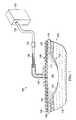
- FIG. 1is a schematic diagram, with a portion shown in cross section and a portion shown in perspective view, of an illustrative embodiment of a reduced-pressure treatment system for treating a tissue site on a patient;
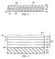
- FIG. 2is a schematic cross section of a portion of a drape according to one illustrative embodiment
- FIG. 3is a schematic cross section of an illustrative embodiment of a holographically-formed polymer dispersed liquid crystal (H-PDLC) device attached as part of a drape;
- H-PDLCholographically-formed polymer dispersed liquid crystal
- FIG. 4Ais a schematic diagram showing a reflective H-PDLC device in two states
- FIG. 4Bis a schematic diagram showing a pass-through (transmission) H-PDLC device in two states
- FIG. 5is a schematic cross section of an illustrative embodiment of an H-PDLC device in an unstrained state
- FIG. 6is a schematic cross section of the illustrative embodiment of the H-PDLC device of FIG. 5 shown strained by a tensile force (strained state);
- FIG. 7is a schematic cross section of the illustrative embodiment of the H-PDLC device of FIG. 5 shown strained by a compressive force;
- FIG. 8is a schematic cross section of an illustrative embodiment of an H-PDLC device having liquid crystal (LC) planes orthogonal to a tensile force;
- LCliquid crystal
- FIG. 9is a schematic cross section of an illustrative embodiment of an H-PDLC device having liquid crystal (LC) planes angled with respect to a tensile force;
- LCliquid crystal
- FIG. 10is a schematic cross section of an illustrative embodiment of a polarization-sensitive H-PDLC device shown in two states;
- FIG. 11Ais a schematic cross section of an illustrative embodiment of a reflective H-PDLC device utilizing aspected H-PDLC particles;
- FIG. 11Bis a schematic cross section of the reflective H-PDLC device of FIG. 11A shown under stress;
- FIG. 12is schematic cross section of an illustrative reflective H-PDLC device that includes two H-PDLC films with liquid crystal (LC) planes having different orientations;
- LCliquid crystal
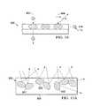
- FIG. 13is a schematic, perspective view of a drape that includes a pressure-indicating device that includes an H-PDLC device;
- FIG. 14is a schematic, elevational view of an illustrative embodiment of a canister for receiving body fluids that has at least one pressure-indicating device that includes an H-PDLC device;
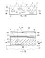
- FIG. 15is a schematic plan view of an illustrative embodiment of a conduit connector for fluidly coupling medical conduits, wherein the conduit connector has a pressure-indicating device that includes an H-PDLC device;
- FIG. 16is a schematic cross section of an illustrative embodiment of a reduced-pressure interface for providing reduced pressure through a drape to a tissue site, wherein the reduced-pressure interface has a pressure-indicating device that includes an H-PDLC device; and
- FIG. 17is a schematic cross section of an illustrative embodiment of a reduced-pressure interface for providing reduced pressure through a drape to a tissue site and having a pressure-indicating device that includes an H-PDLC device.
- straincan indicate the presence of reduced pressure, over-pressurization of a dressing during installation therapy, or over-stretching of the drape during application. Over-stretching the drape during application of the dressing on the patient can cause pain for the patient and ultimately may contribute to non-compliance. Over-stretching may also cause skin marking or irritation. For at least these reasons, a dressing is desired that visually indicates qualitatively or quantitatively the presence of strain.
- the reduced-pressure treatment system 100includes a drape 106 that includes a holographically-formed polymer dispersed liquid crystal (H-PDLC) device 108 .
- the H-PDLC device 108has layers of liquid crystal (LC) droplets in a matrix polymer.
- the H-PDLC device 108is typically a reflective strain gauge as will be described further below.
- the H-PDLC device 108provides a visual indication of stress on the drape 106 by changing colors or otherwise changing visual appearances of ambient light that is reflected to an observer.
- the H-PDLC device 108is associated with the drape 106 and may be attached to one or more polymer layers 109 or may be sandwiched between two elastomeric layers, typically polymer layers 109 , as shown or otherwise incorporated into the drape 106 .
- the H-PDLC device 108may be coextensive with the polymer layer or layers of the drape 106 or may only partially cover the other layers of the drape 106 .
- the H-PDLC device 108may form a plurality of strips or a grid pattern that is attached to a polymer layer or that is sandwiched between polymer layers as an aspect of the drape 106 .
- the drape 106has a surface area A and the H-PDLC device 108 covers 50 percent or less of A. The reduced coverage may help with vapor transmission rates through the drape 106 .
- the drape 106may be any material that provides a fluid seal and is flexible.
- the drape 106may be, for example, an impermeable or semi-permeable, elastomeric material.
- suitable elastomersmay include, but are not limited to, natural rubbers, polyisoprene, styrene butadiene rubber, chloroprene rubber, polybutadiene, nitrile rubber, butyl rubber, ethylene propylene rubber, ethylene propylene diene monomer, chlorosulfonated polyethylene, polysulfide rubber, polyurethane (PU), EVA film, co-polyester, and silicones.
- Additional, specific examples of drape materialsinclude a silicone drape, a 3M Tegaderm® drape, or a polyurethane (PU) drape such as one available from Avery Dennison Corporation of Pasadena, Calif.
- the drape 106includes an attachment device 113 ( FIG. 2 ) on a patient-facing side 107 of the drape 106 .
- the attachment device 113may take numerous forms.
- the attachment device 113may be a medically-acceptable, pressure-sensitive adhesive that extends about a periphery, a portion, or the entire drape 106 .
- the attachment device 113may be a double-sided drape tape, paste, hydrocolloid, hydrogel or other sealing device or element.
- the drape 106may take numerous embodiments.
- the H-PDLC device 108is sandwiched or layered between two members of a plurality of polymer layers 109 .
- a layer 128 that is an optional reflective layermay be on the patient-facing side 130 of the H-PDLC device 108 to make changes in the visual appearance of the H-PDLC device 108 easier to see from a point external to the drape 106 .
- the layer 128may be a light-absorbing layer.
- an optical reader(not shown), e.g., a photodiode, a spectrometer or other suitable instrument for observing a wavelength shift, or an analyzer for observing a polarization-dependent shift in the reflected light, may be associated with the drape 106 for monitoring electronically for any visual changes in the H-PDLC device 108 .
- the drape 106has a first side 105 and a second, patient-facing side 107 .
- the drape 106covers a distribution manifold 110 , which is disposed proximate to the tissue site 102 , e.g., a wound 112 .
- the wound 112is shown through the patient's skin 114 and into subcutaneous tissue 116 .
- the tissue site 102may be the bodily tissue of any human, animal, or other organism, including bone tissue, adipose tissue, muscle tissue, dermal tissue, vascular tissue, connective tissue, cartilage, tendons, ligaments, or any other tissue.
- Treatment of tissue site 102may include removal of fluids, e.g., exudate or ascites.
- the drape 106covers the distribution manifold 110 and a portion of the patient's intact skin 114 to form a sealed space 118 .
- a reduced-pressure interface 120may be fluidly coupled to the sealed space 118 .
- the reduced-pressure interface 120may be fluidly coupled to a reduced-pressure source 122 by a reduced-pressure delivery conduit 124 .
- the reduced-pressure delivery conduit 124may include one or more conduit connectors 126 , which couple conduits to form an integral reduced-pressure delivery conduit 124 .
- the reduced-pressure source 122may be any device for supplying a reduced pressure.
- the reduced-pressure source 122may be a vacuum pump, wall suction, micro-pump, or other source.
- the reduced-pressure source 122typically includes a canister for receiving fluids. While the amount and nature of reduced pressure applied to a tissue site 102 will typically vary according to the application, the reduced pressure will typically be between ⁇ 5 mm Hg ( ⁇ 667 Pa) and ⁇ 500 mm Hg ( ⁇ 66.7 kPa) and more typically between ⁇ 75 mm Hg ( ⁇ 9.9 kPa) and ⁇ 300 mm Hg ( ⁇ 39.9 kPa).
- a reduced-pressure sourcemay be included in the sealed space 118 and provide reduced pressure therein while discharging exhaust outside of the sealed space.
- a micro-pumpsuch as that shown in United States Patent Publication 2009/0240185 (application Ser. No. 12/398,904), entitled, “Dressing and Method for Applying Reduced Pressure To and Collecting And Storing Fluid from a Tissue Site,” which is incorporated herein for all purposes, may be used.
- the drape 106may be used to form a wound dressing that is used without reduced pressure and may be used without a distribution manifold.
- reduced pressureis realized in the sealed space 118 .
- the reduced pressuremay be for reduced-pressure therapy or for removal of fluids.
- Reduced pressurerefers to a pressure less than the ambient pressure at a tissue site 102 that is being subjected to treatment. In most cases, this reduced pressure will be less than the atmospheric pressure at which the patient is located. Alternatively, the reduced pressure may be less than a hydrostatic pressure at the tissue site. Unless otherwise indicated, quantitative values of pressure stated herein are gauge pressures. As previously noted, in some applications, no reduced pressure is used and only a wound dressing that includes the drape 106 is utilized.
- the inclusion of the H-PDLC device 108 as an aspect of the drape 106allows for an indication—qualitatively or quantitatively—of the presence of strain.
- the H-PDLC device 108will provide a change in a visual appearance as will be described further below.
- the H-PDLC device 108may be calibrated such that certain colors or appearances correspond to certain reduced-pressure ranges. As previously mentioned, identifying or even quantifying strain (or stress) has advantages.
- the distribution manifold 110is placed proximate to the tissue site 102 .
- the tissue site 102 and distribution manifold 110are then covered with the drape 106 to form the sealed space 118 .
- the reduced-pressure interface 120is fluidly coupled to the sealed space 118 and to the reduced-pressure delivery conduit 124 .
- Reduced pressureis delivered through the reduced-pressure delivery conduit 124 to the sealed space for reduced-pressure treatment or fluid removal.
- the drape 106experiences a red shift, a blue shift, a polarization change, light intensity change, or another visual change if strained beyond a threshold.
- stressmay be applied to the drape 106 by the action of the reduced pressure resulting in a strain, and in response, the drape 106 may change color or further change color or other visual appearances.
- an optional absorbent layer or other wound-filler materialmay be placed proximate to the tissue site 102 .
- the drape 106is then used to cover the tissue site and the optional absorbent layer or other material if used.
- the visual appearance of the drape 106will change.
- the drape 106and specifically the H-PDLC device 108 , experiences a red shift or blue shift or a polarization change or another visual change.
- the dressingis stretched more than a threshold, e.g., five percent or ten percent, the drape 106 will change visual appearance.
- the H-PDLC device 108 and other devices using H-PDLCwill now be presented.
- the H-PDLC device 108 or other devices hereininclude layers of liquid crystal (LC) droplets in a polymer matrix and may be used as a reflective strain gauge or detector. Strain is observed by a change in the nature of the light reflected or transmitted from the surface of an H-PDLC-containing film. Layers of the H-PDLC film may be positioned in a device such that a force applied to the film changes the wavelength of the reflected light. This is achieved when the applied strain causes the distance between the LC layers to expand or contract. The change in wavelength may be a blue shift or a red shift depending on expansion or contraction. Other embodiments may involve a change in polarization.
- LCliquid crystal
- the H-PDLC filmhas a reflection or transmission grating capable of reflecting or transmitting light of a selected wavelength.
- the H-PDLC filmmay include a means for adhering the H-PDLC film to a surface of a polymer layer of the drape (e.g., drape 106 in FIG. 1 ) or other device (e.g., pressure-indicating devices 814 , 820 , 822 , 824 ( FIG. 14 ); pressure-indicating device 914 ( FIG. 15 ); or pressure-indicating device 1009 ( FIGS. 16-17 )) for monitoring the strain at the surface or at a particular site.
- the H-PDLC filmmay also be laminated within polymer layers or otherwise included in the drape or other devices.
- the H-PDLCmay cover a window and may be coupled to a polymer layer as needed to create a desired tensile strength.
- an illustrative embodiment of an H-PDLC film 200is presented such as forms the H-PDLC device 108 of FIGS. 1 and 2 and other embodiments herein.
- the H-PDLC film 200includes a reflection grating capable of reflecting light of a selected wavelength.
- “reflection grating”means a periodic array of liquid crystal (LC) droplet planes having an orientation and layer spacing sufficient to reflect light of a selected wavelength that is incident on the surface of the grating.
- the strain experienced by the drape or other device in which the H-PDLC film 200 is included or attachedis transmitted to the H-PDLC film 200 .
- the H-PDLC film 200alters the reflective light properties of the H-PDLC film 200 .
- the change in the reflective light properties of the H-PDLC film 200is representative of, and proportional to, the strain experienced by the drape or other device.
- the change in the light reflective propertiesmay be in the intensity of the reflected light, e.g., an “on-off” modality, or it may be in the wavelength of the reflected light, e.g., a wavelength shift.
- the change in the reflected lightmay be observed visually in those cases where the shift is dramatic enough to be observed by the human eye.
- the strain in the drape or other devicemay be observed instrumentally by monitoring the intensity of the reflected light using a photodiode, observing a wavelength shift using a spectrometer or other suitable instrument, or by observing a polarization-dependent shift in the reflected light by incorporating an analyzer between the H-PDLC film 200 and the detector.
- H-PDLC filmsare phase-separated compositions formed under holographic conditions. Instead of random arrangement of LC droplets, holographic exposure induces a periodic array of LC droplets and matrix polymer planes, as shown in FIGS. 4A and 4B .
- the monomerdiffuses to highlight intensity regions where the monomer polymerizes.
- the liquid crystalremains in the dark regions and phase separates into small droplets 302 on the order of nanometers, e.g., 10-200 nm, in ordered, stratified layers 304 .
- the actual phase-separated morphologyvaries dependent upon the particular liquid crystal and the relative composition of the liquid crystal and matrix polymer 306 used.
- spherical or ellipsoidal LC dropletsare localized in stratified layers and are completely surrounded by matrix polymer 306 .
- connectivity between the LC dropletsmay be observed.
- Morphology of the resultant compositionalso depends on the polymer (composition, molecular weight, or other variables). For example, higher molecular weight polymers tend to favor phase-separation.
- the refractive index of the LC droplet planes or stratified layers 304 (n LC )is different from that of the matrix polymer 306 planes (n p )
- light of a specific wavelengthis reflected by the periodic modulation in the refractive index, which is illustrated in the left portion of FIG. 4A .
- n LCis equal to n p
- the periodic refractive index modulationdisappears and the incident light is transmitted through, as is illustrated in the right portion of FIG. 4A .
- the interference patterncan be selected to form Bragg gratings that can reflect any visible light.
- the reflection intensityis determined by the effective refractive index of the LC droplet planes.
- the Bragg reflectionoccurs in either the reflection mode ( FIG. 4A ) or diffraction mode ( FIG. 4B ) depending on the orientation of the Bragg grating. This, in turn, is dependent upon the beam geometry during phase separation.
- transmission gratingis a periodic array of LC droplet planes having an orientation and layer spacing sufficient to diffract light and to transmit light of a selected wavelength. In those instances it is desirable that the device (e.g., pressure-indicator) be translucent so that changes in the transmitted light are observable.
- the adhesive that may be used to couple the H-PDLC film to other portions of the drapemay be any material which forms a surface conforming bond between two substrates.
- the adhesivedesirably transfers strain from the drape to the H-PDLC film to thereby deform the film with the resultant change in reflected light.
- the adhesiveshould be sufficiently compliant so that the adhesive does not interfere with the transmission of strain from the surface of the other drape components or device components to the H-PDLC film.
- the desired materials properties for an adhesiveinclude a low elastic modulus, a high yield strength, high adhesion, and a high coefficient of friction, i.e., the interfaces between the adhesive and device and between the adhesive and H-PDLC film do not slip.
- the adhesivealso may be relatively temperature-insensitive, that is, the adhesive may possess a low thermal expansion co-efficient and may be largely unaffected by water (moisture-insensitive) for those applications where the gauge is to be used outdoors, in moist environments, or in temperature extremes.
- the H-PDLCmay be sandwiched between polymer layers.
- the H-PDLC film 200is coupled to the first side 202 of a polymer layer 204 of a drape 206 (or device).
- the H-PDLC film 200may be coupled using an adhesive layer 208 .
- the H-PDLC film 200has liquid crystal (LC) layers 210 in a matrix polymer 212 .
- the stratified arrangement of LC layers 210 in the matrix polymer 212gives rise to a reflection grating that reflects a particular wavelength of light. The exact wavelength is determined by the size of the spacing between the LC layers 210 , indicated by dimension 214 .
- the liquid crystal layers 210are shown in FIG. 3 at an orientation substantially parallel to the drape 206 (or device).
- the LC layers 210may have any desired orientation and may be located, for example, perpendicular to or at any other intermediate angle with respect to the polymer layer 204 .
- the H-PDLC film 200may be any conventional film capable of reflection of a selected wavelength of light. It should be understood that the number of LC layers 210 is shown schematically and any number of layers may be used in the H-PDLC film 200 . For the purposes of simplicity, only a few layers are shown.
- the shift in wavelength with strainis a function of the extent of d-spacing contraction or expansion of the LC layers 210 .
- the figuresillustrate the basis for the observed wavelength shift in the H-PDLC films 200 .
- the liquid crystal (LC) layers 210in the unstrained state, have a spacing “d” indicated by dimension 214 .
- the strainis transmitted through the drape or device into the H-PDLC film 200 .
- a pressurized gasmay act directly on the H-PDLC film 200 , e.g., when covering a non-conformable window frame such as that shown in FIG. 14 .
- the strainmay be applied when, for example, a reduced pressure is applied to the sealed space, when the patient moves, when the drape is applied, when a positive pressure applied with the installation of a fluid, or other circumstances.
- the H-PDLC film 200Under the tensile force 218 , the H-PDLC film 200 is stretched and the film thickness contracts, with a corresponding contraction of the LC layers 210 . As a result, the H-PDLC film 200 develops a new d-spacing indicated by dimension 220 .
- the new d-spacing 220gives rise to reflection of light of a different wavelength ⁇ 2 . With a contraction of the d-spacing, a shift of the reflected light towards the blue region in the visible spectrum (blue shift) is observed for the same viewing angle.
- a compressive forceis applied to the H-PDLC film 200 .
- the compressive force 222may also give rise to a new d-spacing indicated by dimension 224 and resulting in a blue shift in the reflected light.
- H-PDLC films 200may also be used in pressure-sensing devices. If the H-PDLC film 200 is suspended, as in a window, the compressive force may stretch as well as compress the LC layers 210 .
- the figuresillustrate circumstances in which the LC layers 210 may be expanded rather than contracted upon application of a tensile force.
- the LC layers 210have a vertical orientation vis-à-vis the tensile force 218 .
- the tensile force 218urges the LC layers 210 outward and may give rise to an expansion of the d-spacing 226 between LC layers 210 .
- the expansion between LC layers 210results in a shift to higher wavelengths, i.e., a red shift.
- the H-PDLC film 200is, thus, set up in a transmission mode due to the perpendicular orientation of the LC layers 210 .
- the transmitted lighthowever, would experience the same wavelength shift as described above for reflected light. As in the reflection mode, the wavelength shift is proportional to strain experienced in the drape or device.
- the LC layers 210are not in alignment with or orthogonal to the direction of the applied tensile force 218 .
- the tensile force 218is applied at an angle ⁇ with respect to the LC layers 210 , where ⁇ is the angle between the vectors of the applied force 218 and the LC layers 210 .
- the change in d-spacing represented by dimension 228 (and the resultant wavelength)is non-linear.
- the response of the LC layers 210 to the applied forceis complex because both a compressive and tensile component are present.
- the fractional wavelength shiftis approximately one-half the strain in the sample.
- the fractional shiftis approximately equal to the strain and is therefore more sensitive. It may, however, be more difficult to measure a shift in wavelength reflection under these conditions.
- the red shift due to stretching of the LC layers 210will be somewhat balanced by the blue shift due to Poisson-type contraction and an H-PDLC film 200 may be obtained that is substantially insensitive to stress in one direction. A wavelength shift may then be observed, but only in a direction substantially orthogonal to that which is stress-insensitive (a blue-shift would occur due to LC layer contraction).
- the differing sensitivities of the H-PDLC film 200 to stress in different directionspermit the design of H-PDLC films 200 in which the direction, as well as the magnitude, of strain may be determined.
- orientation of the LC layer 210is useful in determining not only the existence of strain but its directionality. As discussed herein, the directionality of the applied stress and the orientation of the LC layers 210 can result in either a contraction, expansion or no change of the LC layer spacings (dimensions) 214 , 220 , 224 , 226 , 228 . Moreover, some LC layer 210 orientations are more sensitive than others to contraction or expansion of the d-spacing. This can provide valuable information as to the forces experienced by the drape or device.
- the stressmay be additionally possible to identify where on the drape or device surface the stress is experienced. For example, if the strain is experienced locally on the surface of the drape, only a subsection of the H-PDLC film 200 associated with the drape or device surface would be subjected to the tensile or pressure forces which alter the reflection properties of the H-PDLC film 200 . By observing the region of the H-PDLC film 200 undergoing a wavelength shift or change in visual appearance, the strain site may be identified.
- the applied forcemay be proportional to strain and may be related to the strain experienced in the drape or device.
- Uniaxial extension of a reflective H-PDLC filmnot only shifts the reflected wavelength, it also introduces a polarization dependence onto the observed reflected light.
- Polarizationis manifested in differences in peak reflected wavelength and in the reflection efficiency for light polarized parallel (pi) and perpendicular (sigma) to the tensile axis.
- the polarization effectarises when the stresses on the film are sufficient to deform the LC droplets into prolate ellipsoids with the long axis aligned parallel to the tensile axis.
- the most energetically favorable droplet configuration for a prolate ellipsoid for homogeneous anchoring of the LC to the polymeris bipolar, with the symmetry axis of the droplet parallel to the long axis.
- the polarization effectis slight.
- molecular orientation of the LC dropletsoccurs in addition to the d-spacing contraction previously discussed.
- the strain regime which is most likely to be monitored by the filmis in the range of 1-20%, and so the polarization effect is likely to be observed and to be a factor in interpreting the information obtainable from the film.
- the refractive index of the LC dropletis greater parallel to the symmetry axis than perpendicular.
- the symmetry axes of the dropletsare oriented randomly throughout the film and the modulation of the refractive index through the film is the same both parallel and perpendicular to the tensile axis.
- the alignment of the dropletsmeans that the average refractive index and the index amplitude modulation are greater parallel to the tensile axis than perpendicular.
- the difference in profilesaccounts for both the peak wavelength being lower for light polarized perpendicular and the lower reflection efficiencies for the sigma-polarized state.
- the change in refractive indexis small because the average refractive index of the droplets is closer to the ordinary refractive index, n o , and therefore more closely matches the polymer (n o ⁇ n p ).
- the refractive indexis weighted more towards the extraordinary refractive index, n e , and the average refractive index is higher, thus increasing the optical path length between planes relative to the sigma state and increasing the peak reflected wavelength.
- the amplitude of the refractive index modulationis also greater, resulting in greater efficiencies than the sigma-state.
- an H-PDLC film 400may include a polarization-dependent H-PDLC film as described above.
- a polarization-dependent H-PDLC filmas described above.
- sigma-polarized lightis transmitted through the film, while pi-polarized light is reflected.
- Use of polarized lightprovides an H-PDLC film, or visual strain gauge, with an “on-off” indicator for surface strain, as compared to the “blue-green” indicator (or the like) for non-polarized H-PDLC films.
- the H-PDLC film 400may have an average refractive index very close to that of the matrix polymer in the unstrained state and an average refractive index approaching n e in the strained state. Because of the similarity of the refractive indices, no reflection grating is perceived by incident light in the unstrained state and light is transmitted through the H-PDLC film 400 .
- the H-PDLC film 400When the H-PDLC film 400 is stressed, however, the H-PDLC film 400 deforms and the LC droplets molecularly orient to form polarized droplets having a higher refractive index than the surrounding matrix polymer. And, the reflection grating suddenly forms which reflects light of the selected wavelength. If the sample is illuminated with sigma-polarized light (arrow 402 ) as shown on the left-hand portion (for the orientation shown) of FIG. 10 , no reflection is observed. If the light is illuminated with pi-polarized light (arrow 404 ) as shown on the right-hand portion (for the orientation shown) of FIG. 10 , a reflection is observed. Monitoring for an on-off indication may be easier in some circumstances than monitoring for a colorshift.
- Polarization-dependent light reflectionprovides additional advantages, such as increased reflection efficiency, and provides information on the directionality of the strain.
- Information regarding strain directionalitymay be obtained even if there is no discernible wavelength shift of the reflected light.
- a film such as that shown in FIG. 9may have LC planes at an angle ⁇ that is stress-insensitive, that is, the d-spacing remains unchanged when stressed. Even so, the LC droplets may respond by aligning with the applied stress. Molecular alignment may be observed by scanning the film with a polarizer and noting the angles of increased intensity.
- polarized H-PDLC films 400 formed by stretchingcould be used to form polarization gratings.
- unpolarized lightilluminates the polarized H-PDLC films 400
- sigma-polarized lightwill pass through the film without deflection, while pi-polarized light is reflected.
- pi-polarized lightis reflected.
- only sigma-polarized lightcan pass through the film and can thereby serve as a polarizing light filter. This may be more useful on windows of devices, e.g., non-conformable window 916 ( FIG. 15 ).
- the H-PDLC filmincludes aspected particles made up of the H-PDLC materials randomly dispersed in a supporting polymer which may be the same as that used in the H-PDLC aspected particles, or different.
- the matrixshould, however, exhibit the desired response to applied strain; that is, it should be elastic, have high yield strength and a high strain tolerance to avoid failure under the anticipated use conditions.
- the aspected particlescontain at least one dimension which is large with respect to the remaining dimension(s). Due to the aspected nature of the particles, the particles will rotate or otherwise orient themselves under an applied force so that the particles are aligned. The greater the aspect ratio, the greater the alignment force.
- the aspect ratio (dimension of the long to short dimensions) of the H-PDLC particlesis preferably at least 2:1, more preferably at least 4:1, more preferably at least 10:1 and preferable at least 20:1.
- an H-PDLC film 500 made up of aspected H-PDLC particles 502 in the unstrained stateis depicted.
- the particles 502are randomly distributed throughout a polymer matrix 504 with no preferred direction of orientation.
- the incident lightis reflected back to the observer at various angles and the visual effect is indistinct.
- the particles 502Under an applied force indicated by arrows 506 in FIG. 11B , the particles 502 orient due to torque on the rod-like particles and the reflected image becomes more intense.
- the sudden increase in color sharpness and brightnessis an indication that the surface of the drape or device has been stressed.
- an H-PDLC filmwhich contains two or more reflection gratings.
- the reflection gratingsmay be located in different H-PDLC films that are layered to form a multilayer H-PDLC film.
- the reflection gratingsmay be located within the same film, either by being written into the same portion of the film (overlapping), or by forming different gratings in different and non-overlapping regions of the same film.
- the multiple reflection gratingsmay have the same d-spacing, yet differ from one another by the orientation of the gratings with respect to the drape or device surface.
- the response of the grating to an applied forcedepends upon the relationship between the two, which is defined by the angle ⁇ .
- LC layersmay be strain-insensitive in certain directions, and so directionality of the applied force may be determined.
- a single H-PDLC filmmay include a plurality of gratings at different angles, so that a strain response may be observed by at least one grating in any direction. This increases the useful operation range of the H-PDLC film as well as provides valuable information regarding the tensor of the applied stress. When the gratings reflect at different wavelengths (colors), then the observed, reflected wavelength may be attributed to the appropriate grating and the directionality of the stress is known.
- the H-PDLC filmmay include films having reflection gratings of different d-spacings, which are capable of reflecting light of different wavelengths.
- the reflection gratingsmay be oriented to respond to stress applied in different directions. Depending upon which reflection grating exhibited a shift in reflected wavelength (or demonstrated an “on-off” shift or a polarization shift in the case of polarized films), the H-PDLC film indicates the direction of the applied stress. It may also be possible to arrange the layers such that one reflection grating shifts red under the applied strain, while a second layer shifts blue.
- an H-PDLC film 600has a first H-PDLC layer 602 and a second H-PDLC layer 604 .
- Each H-PDLC layer 602 , 604is made up of a reflection grating at a different orientation with respect to the first surface 606 of the drape or device 608 .
- the first H-PDLC film 602may include a reflection grating having LC layers at a first angle ⁇ 1 (shown as layers sloping downward and into the plane of the paper) to the surface or side 606 and having a d-spacing to reflect red light.
- the second H-PDLC film 604may include a reflection grating having LC layers at a second angle ⁇ 2 to the first surface 606 and having a d-spacing to reflect green light.
- Each LC layeris stress-insensitive to a different stress vector.
- each layerreflects light of a different wavelength and will respond with a shift in their reflection profile when subjected to strains in different directions.
- the different reflection gratingsneed not be found in different layers.
- the reflection gratingsmay be positioned in the same film.
- the H-PDLC first layer 602may be stretched along the length of the LC planes (denoted by large arrow 610 ). When the drape or device 608 experiences a stress along this axis, the d-spacings of the first H-PDLC layer 602 contract and a blue shift of the red reflecting light 612 occurs. When observing light reflection at the angle defined for first H-PDLC layer 602 a strong shift in the reflected light is observed.
- the second H-PDLC layer 604is stress-insensitive and light reflecting from it does not shift in wavelength.
- the first H-PDLC layer 602is subjected to a stress along the direction noted by arrow 614 , no net change of the LC layer spacing occurs and no shift in the reflected light is observed.
- the second H-PDLC layer 604is greatly effected by this stress vector and a change in the reflected light 616 is observed.
- Multiple grating filmsmay be prepared by exposing an H-PDLC precursor film to a plurality of interfering photopolymerizing interference patterns. Each interference pattern results in a reflection grating having characteristic LC plane orientation and d-spacing. These are only some illustrative embodiments for the H-PDLC device.
- FIGS. 1-2present two illustrative embodiments involving the H-PDLC device 108 in a drape 106 , but other devices and approaches may be used.
- the H-PDLC devicemay be used in a window that is installed in the drape.
- FIG. 13an illustrative embodiment of a drape 700 that may be used as an aspect of a reduced-pressure system, such as the reduced-pressure treatment system 100 of FIG. 1 , is presented.
- the drape 700includes a pressure-indicating device 702 , or pressure-indicating sensor.
- the pressure-indicating device 702includes a non-conformable window frame 704 over which an H-PDLC device or film 706 has been applied.
- the H-PDLC device or film 706may include an H-PDLC device of the type previously discussed.
- additional polymer layersmay be added to adjust the tensile strength of the H-PDLC device 706 .
- the pressure-indicating device 702 on the drape 700functions as a pressure sensor for a sealed space, such as sealed space 118 in FIG. 1 , created in part by the drape 700 .
- the pressure differential across (the greater pressure on the side opposite the patient-facing side) the drape 700causes the drape 700 to experience stress that causes strain.
- the resultant strainchanges the visual appearance of the H-PDLC device 706 .
- a second, analogous pressure-indicating device(not explicitly shown but analogous to pressure-indicating device 702 ) may be applied to the drape 700 to indicate positive pressure in the sealed space (greater pressure on the patient-facing side). For example, when a fluid, e.g., a saline wash or liquid medicine, is inserted into the sealed space, the second window experiences a positive pressure on the patient-facing side.
- the drape 700may optionally include two or more pressure-indicating devices for measuring reduced pressure and positive pressure or for indicating different pressure ranges of positive pressure or negative pressure.
- a plurality of pressure-indicating devicesmay be used with each having a different pressure threshold at which the visual appearance changes. In this way, the approximate pressure in the sealed space may be indicated.
- the canister 800may be used as part of a reduced-pressure treatment system, such as the reduced-pressure treatment system 100 of FIG. 1 .
- the canister 800has a canister body 802 formed with a fluid reservoir 804 (shown in hidden lines).
- the canister 800includes an inlet 806 for receiving a first reduced-pressure delivery conduit 808 from a tissue site (e.g., tissue site 102 in FIG. 1 ). Reduced pressure may be developed within the canister body 802 or may be delivered through a suction inlet 810 that is coupled to a second reduced-pressure delivery conduit 812 .
- At least one pressure-indicating device 814is included on the canister 800 with fluid access to the fluid reservoir 804 .
- the pressure-indicating device 814includes a non-conformable window frame 816 that is coupled to the canister body 802 .
- the non-conformable window frame 816is covered by a holographically-formed polymer dispersed liquid crystal (H-PDLC) device 818 of the type previously described.
- the H-PDLC device 818 of the pressure-indicating device 814changes visual appearances when experiencing strain caused by reduced pressure (or alternatively positive pressure) within the fluid reservoir 804 .
- the visual appearanceoccurs when the pressure is within a first range.
- the strainmay be optionally correlated with reduced-pressure ranges in the fluid reservoir 804 to provide a specific range indication corresponding to visual indicia 826 .
- a plurality of pressure-indicating devicesmay be included on the canister 800 .
- the plurality pressure-indicating devicesincludes at least two devices, and the pressure-indicating devices change visual appearances for strains of different ranges.
- four pressure-indicating devicesare included with each being activated (i.e., changing visual appearance) over a different pressure range.
- the first pressure-indicating device 814changes visual appearance when the reduced pressure in the fluid reservoir 804 is in the range of ⁇ 90 to ⁇ 100 mm Hg.
- the second pressure-indicating device 820changes visual appearance when experiencing pressure in the range of ⁇ 100 to ⁇ 110 mm Hg.
- the third pressure-indicating device 822changes visual appearance when experiencing pressure in the range of ⁇ 110 to ⁇ 120 mm Hg.
- the fourth pressure-indicating device 824changes visual appearance when experiencing pressure in the range of ⁇ 120 to ⁇ 130 mm Hg.
- the non-conformable window frame 816may itself be in the shape of visual indicia indicating a pressure range associated with the magnitude of strain that causes holographically-formed polymer dispersed liquid crystal (H-PDLC) device for that window to change colors.
- the window frameitself may form the letters “ ⁇ 100/ ⁇ 110 mm Hg.” When a strain indicative of that pressure range is reached, the color (or other visual appearance) of the H-PDLC device visible through the letters changes.
- the conduit connector 900may be used to connect a first medical conduit 902 and a second medical conduit 904 while providing some pressure information.
- the conduit connector 900may be used to connect the two portions or segments of the reduced-pressure delivery conduit 124 in FIG. 1 and used as part of a reduced-pressure treatment system, such as the reduced-pressure treatment system 100 in FIG. 1 .
- the conduit connector 900includes a connector body 906 .
- the connector body 906has a chamber 908 .
- the chamber 908has an inlet 910 for receiving and coupling with the first medical conduit 902 and an outlet 912 for receiving and coupling with the second medical conduit 904 .
- a pressure-indicating device 914is formed on the connector body 906 .
- the pressure-indicating device 914comprises a non-conformable window frame 916 covered with a holographically-formed polymer dispersed liquid crystal (H-PDLC) device 918 of the type previously described.
- H-PDLCholographically-formed polymer dispersed liquid crystal
- the conduit connector 900may be used with a reduced-pressure treatment system to provide a visual indication of reduced pressure existing within the reduced-pressure delivery conduit or medical conduits 902 , 904 .
- the reduced pressureis fluidly communicated to the chamber 908 and will cause a pressure differential across the H-PDLC device 918 that places a stress on the H-PDLC device 918 .
- the stressin turn causes a strain to be experienced by the H-PDLC device 918 that changes the visual appearance of the H-PDLC device 918 .
- the change in visual appearancesthereby indicates the presence of reduced pressure.
- the H-PDLC device 918may be calibrated to change to a particular visual appearance, e.g., a certain color, when the reduced pressure is in a desired pressure range.
- a reduced-pressure interface 1000for providing reduced pressure through a drape 1002 to a tissue site 1004 is presented.
- the reduced-pressure interface 1000may be used as part of a reduced-pressure treatment system, e.g., the reduced-pressure treatment system 100 of FIG. 1 .
- the drape 1002covers a distribution manifold 1006 and forms a sealed space 1008 .
- the reduced-pressure interface 1000includes a pressure-indicating device 1009 for providing a visual indication of the presence of reduced pressure in the sealed space 1008 or a positive pressure in the sealed space 1008 .
- the pressure-indicating devicemay be calibrated to indicate a particular pressure range.
- the reduced-pressure interface 1000includes an interface body 1010 .
- the interface body 1010has a base 1012 and a suction head 1014 .
- the suction head 1014includes a conduit opening 1016 for fluidly coupling to a reduced-pressure delivery conduit 1018 and a delivery opening 1020 for communicating reduced pressure to the tissue site 1004 .
- a passageway 1019 in the interface body 1010fluidly couples the conduit opening 1016 and the delivery opening 1020 .
- the interface body 1010includes a pressure-indicating device 1009 .
- the pressure-indicating device 1009comprises a holographically-formed polymer dispersed liquid crystal (H-PDLC) device 1022 of the type previously described having layers of liquid crystal (LC) droplets in a matrix polymer.
- the H-PDLC device 1022may be attached to a polymer layer 1024 or sandwiched by polymer layers 1024 , 1026 .
- the pressure-indicating device 1009includes an aperture or non-conforming window 1028 formed in the base 1012 that is covered by the holographically-formed polymer dispersed liquid crystal (H-PDLC) device 1022 .
- An aperture 1030 corresponding to and aligned with pressure-indicating device 1009may be formed in the drape 1002 to provide fluid communication between the sealed space 1008 and the H-PDLC device 1022 (or the polymer layer 1026 adjacent to the H-PDLC device 1022 ). Thus, the pressure in the sealed space 1008 is communicated to the H-PDLC device 1022 .
- the distribution manifold 1006is placed proximate to the tissue site 1004 and covered by the drape 1002 to form the sealed space 1008 .
- the reduced-pressure interface 1000may be pre-installed (installed before use) on the drape 1002 or attached at the time of use.
- An aperture 1032is formed in the drape 1002 and the delivery opening 1020 is positioned over the aperture 1032 .
- the reduced-pressure interface 1000includes an adhesive or other attachment device on a patient-facing side 1034 that attaches the reduced-pressure interface 1000 to a first side 1036 of the drape 1002 .
- the reduced-pressure delivery conduit 1018is fluidly coupled to the conduit opening 1016 . Reduced pressure is supplied to the sealed space 1008 .
- the reduced pressureis communicated to the pressure-indicating device 1009 .
- the H-PDLC device 1022 in the pressure-indicating device 1009experiences a stress from the pressure. Once the resultant strain caused by the stress reaches a calibrated range for the H-PDLC device 1022 (i.e., is greater than a threshold pressure), the H-PDLC device 1022 changes visual appearance. The visual appearance may indicate merely the existence of reduced pressure beyond the threshold pressure or may designate a precise reduced pressure range.
- the reduced-pressure interface 1000is analogous in most respects to the reduced-pressure interface 1000 of FIG. 16 .
- the reduced-pressure interface 1000includes an interface body 1010 having a base 1012 , a suction head 1014 , and a passageway 1019 .
- the suction head 1014includes an assessment chamber 1038 having a chamber wall 1040 .
- the pressure-indicating device 1009is formed on the chamber wall 1040 .
- An aperture, or window 1042is formed on the chamber wall 1040 .
- the window 1042is covered with a holographically-formed polymer dispersed liquid crystal (H-PDLC) device 1022 of the type previously described to form the pressure-indicating device 1009 .
- the H-PDLC device 1022may be attached to a polymer layer or sandwiched by polymer layers. Reduced pressure in the passageway 1019 between a conduit opening 1016 and a delivery opening 1020 is fluidly coupled to the assessment chamber 1038 by an aperture 1044 in a passageway wall 1046 of the suction head 1014 .
- the reduced-pressure interface 1000 of FIG. 17is used analogously to the reduced-pressure interface 1000 of FIG. 16 , except that the pressure-indicating device 1009 receives reduced pressure (or positive pressure) from the passageway 1019 .
- the passageway 1019is fluidly coupled to a sealed space (e.g., sealed space 1008 of FIG. 16 ) over the tissue site.
- the pressure-indicating device 1009may indicate the existence of stress caused by reduced pressure or by positive pressure when fluids are being delivered.
- a method for treating a woundincludes preparing the wound and covering the wound with a drape.
- Preparing the woundmay be include cleaning the wound and applying a medicament, such as an antibiotic.
- the drapecomprises a holographically-formed polymer dispersed liquid crystal (H-PDLC) device of the type previously described having layers of liquid crystal (LC) droplets in a matrix polymer.
- the drapeis configured to change visual appearance when subjected to a strain greater than a threshold strain.
- the methodfurther includes confirming that that the drape has not experienced a change in visual appearance indicative of a strain greater than the threshold strain.
- the methodmay also include disposing a wound filler on the wound.
- the wound fillermay be any substance for wicking fluids away from the wound or alternatively or additionally providing moisture to the wound.
- Example of wound fillersinclude, without limitation, foam, gauze, hydrocolloid, or felted mat.
Landscapes
- Health & Medical Sciences (AREA)
- Heart & Thoracic Surgery (AREA)
- Public Health (AREA)
- Vascular Medicine (AREA)
- Engineering & Computer Science (AREA)
- Biomedical Technology (AREA)
- Veterinary Medicine (AREA)
- Life Sciences & Earth Sciences (AREA)
- Animal Behavior & Ethology (AREA)
- General Health & Medical Sciences (AREA)
- Anesthesiology (AREA)
- Hematology (AREA)
- Physics & Mathematics (AREA)
- General Physics & Mathematics (AREA)
- Liquid Crystal (AREA)
- Materials For Medical Uses (AREA)
Abstract
Description
Claims (26)
Priority Applications (1)
| Application Number | Priority Date | Filing Date | Title |
|---|---|---|---|
| US13/532,058US8827973B2 (en) | 2011-06-24 | 2012-06-25 | Medical drapes, devices, and systems employing a holographically-formed polymer dispersed liquid crystal (H-PDLC) device |
Applications Claiming Priority (2)
| Application Number | Priority Date | Filing Date | Title |
|---|---|---|---|
| US201161500945P | 2011-06-24 | 2011-06-24 | |
| US13/532,058US8827973B2 (en) | 2011-06-24 | 2012-06-25 | Medical drapes, devices, and systems employing a holographically-formed polymer dispersed liquid crystal (H-PDLC) device |
Publications (2)
| Publication Number | Publication Date |
|---|---|
| US20120330252A1 US20120330252A1 (en) | 2012-12-27 |
| US8827973B2true US8827973B2 (en) | 2014-09-09 |
Family
ID=46466929
Family Applications (1)
| Application Number | Title | Priority Date | Filing Date |
|---|---|---|---|
| US13/532,058Active2033-01-18US8827973B2 (en) | 2011-06-24 | 2012-06-25 | Medical drapes, devices, and systems employing a holographically-formed polymer dispersed liquid crystal (H-PDLC) device |
Country Status (2)
| Country | Link |
|---|---|
| US (1) | US8827973B2 (en) |
| WO (1) | WO2012178161A1 (en) |
Cited By (7)
| Publication number | Priority date | Publication date | Assignee | Title |
|---|---|---|---|---|
| US20120310181A1 (en)* | 2010-02-23 | 2012-12-06 | L-Vad Technology, Inc. | Vacuum assisted percutaneous appliance |
| US20160069757A1 (en)* | 2013-05-03 | 2016-03-10 | Indian Council Of Medicalresearch | Non-Contact Method for Measurement of Strain Profile at a Location Interposed within a Soft Deformable Object with Dynamic Evolution of the Strain Under Dynamic Loading or Fracture of the Object |
| US9427430B2 (en) | 2013-03-14 | 2016-08-30 | Kci Licensing, Inc. | Compression bandage having an integrated strain gauge |
| US10729507B2 (en) | 2017-01-12 | 2020-08-04 | Warsaw Orthopedic, Inc. | Surgical draping system and method for using same |
| WO2021224585A1 (en)* | 2020-05-04 | 2021-11-11 | Smiths Medical International Limited | Closed-system suction catheter assemblies and methods |
| US11402267B2 (en)* | 2018-11-02 | 2022-08-02 | Boe Technology Group Co., Ltd. | Light splitting device and method for manufacturing the same, method for dispersing light, and spectrometer |
| RU2822100C2 (en)* | 2022-06-02 | 2024-07-01 | Общество с ограниченной ответственностью "МОТОРИКА" | Method of measuring pressing force by optical anisotropic diffusion strain measurement and sensor for measuring pressing force |
Families Citing this family (37)
| Publication number | Priority date | Publication date | Assignee | Title |
|---|---|---|---|---|
| WO2013066426A2 (en) | 2011-06-24 | 2013-05-10 | Kci Licensing, Inc. | Reduced-pressure dressings employing tissue-fixation elements |
| WO2012178161A1 (en)* | 2011-06-24 | 2012-12-27 | Kci Licensing, Inc. | Medical drapes, devices, and systems employing a holographically-formed polymer dispersed liquid crystal (h-pdlc) device |
| CN107252383A (en) | 2011-07-14 | 2017-10-17 | 史密夫及内修公开有限公司 | Wound dressing and treatment method |
| CN105250077B (en)* | 2015-11-03 | 2018-08-14 | 中国人民解放军第四军医大学 | A kind of applicator that heart pass postoperative wound infection splits |
| US20190076298A1 (en)* | 2016-03-14 | 2019-03-14 | Smith & Nephew Plc | Wound dressing apparatus with flexible display |
| CA3023772A1 (en) | 2016-05-13 | 2017-11-16 | Smith & Nephew Plc | Sensor enabled wound monitoring and therapy apparatus |
| GB2555584B (en) | 2016-10-28 | 2020-05-27 | Smith & Nephew | Multi-layered wound dressing and method of manufacture |
| WO2018132482A1 (en)* | 2017-01-10 | 2018-07-19 | Cornell University | Sensors with elastomeric foams and uses thereof |
| US11690570B2 (en) | 2017-03-09 | 2023-07-04 | Smith & Nephew Plc | Wound dressing, patch member and method of sensing one or more wound parameters |
| EP3592230A1 (en) | 2017-03-09 | 2020-01-15 | Smith & Nephew PLC | Apparatus and method for imaging blood in a target region of tissue |
| JP7091356B2 (en) | 2017-03-09 | 2022-06-27 | スミス アンド ネフュー ピーエルシー | Devices, devices, and methods for determining skin perfusion pressure |
| CA3059516A1 (en) | 2017-04-11 | 2018-10-18 | Smith & Nephew Plc | Component positioning and stress relief for sensor enabled wound dressings |
| EP3635733A1 (en) | 2017-05-15 | 2020-04-15 | Smith & Nephew plc | Negative pressure wound therapy system using eulerian video magnification |
| AU2018269112B2 (en) | 2017-05-15 | 2024-05-02 | Smith & Nephew Plc | Wound analysis device and method |
| JP7189159B2 (en) | 2017-06-23 | 2022-12-13 | スミス アンド ネフュー ピーエルシー | Sensor placement for sensor-enabled wound monitoring or therapy |
| GB201809007D0 (en) | 2018-06-01 | 2018-07-18 | Smith & Nephew | Restriction of sensor-monitored region for sensor-enabled wound dressings |
| GB201804502D0 (en) | 2018-03-21 | 2018-05-02 | Smith & Nephew | Biocompatible encapsulation and component stress relief for sensor enabled negative pressure wound therapy dressings |
| SG11202000913XA (en) | 2017-08-10 | 2020-02-27 | Smith & Nephew | Positioning of sensors for sensor enabled wound monitoring or therapy |
| CN111093477B (en) | 2017-09-10 | 2023-09-12 | 史密夫及内修公开有限公司 | Systems and methods for inspecting packages and components in sensor-equipped wound dressings |
| GB201718870D0 (en) | 2017-11-15 | 2017-12-27 | Smith & Nephew Inc | Sensor enabled wound therapy dressings and systems |
| GB201804971D0 (en) | 2018-03-28 | 2018-05-09 | Smith & Nephew | Electrostatic discharge protection for sensors in wound therapy |
| GB201718859D0 (en) | 2017-11-15 | 2017-12-27 | Smith & Nephew | Sensor positioning for sensor enabled wound therapy dressings and systems |
| WO2019063481A1 (en) | 2017-09-27 | 2019-04-04 | Smith & Nephew Plc | Ph sensing for sensor enabled negative pressure wound monitoring and therapy apparatuses |
| WO2019072531A1 (en) | 2017-09-28 | 2019-04-18 | Smith & Nephew Plc | Neurostimulation and monitoring using sensor enabled wound monitoring and therapy apparatus |
| WO2019089118A1 (en)* | 2017-10-30 | 2019-05-09 | Kci Licensing, Inc. | Systems, apparatuses, and methods for negative-pressure treatment with pressure delivery indication |
| US11559438B2 (en) | 2017-11-15 | 2023-01-24 | Smith & Nephew Plc | Integrated sensor enabled wound monitoring and/or therapy dressings and systems |
| WO2019199849A1 (en)* | 2018-04-13 | 2019-10-17 | Kci Licensing, Inc. | Dressing bolster with area pressure indicator |
| GB201814011D0 (en) | 2018-08-29 | 2018-10-10 | Smith & Nephew | Componet positioning and encapsulation for sensor enabled wound dressings |
| EP3849401A1 (en) | 2018-09-12 | 2021-07-21 | Smith & Nephew plc | Device, apparatus and method of determining skin perfusion pressure |
| WO2020064937A1 (en) | 2018-09-28 | 2020-04-02 | T.J.Smith And Nephew,Limited | Optical fibers for optically sensing through wound dressings |
| GB201816838D0 (en) | 2018-10-16 | 2018-11-28 | Smith & Nephew | Systems and method for applying biocompatible encapsulation to sensor enabled wound monitoring and therapy dressings |
| GB201820927D0 (en) | 2018-12-21 | 2019-02-06 | Smith & Nephew | Wound therapy systems and methods with supercapacitors |
| US12403213B2 (en)* | 2019-01-23 | 2025-09-02 | Solventum Intellectual Properties Company | Wound dressing with selective and dynamic transparency |
| US10989523B2 (en)* | 2019-03-14 | 2021-04-27 | The Boeing Company | Sub-surface patterning for diffraction-based strain measurement and damage detection in structures |
| JP7529681B2 (en) | 2019-03-18 | 2024-08-06 | スミス アンド ネフュー ピーエルシー | Design rules for sensor integrated boards |
| GB201914443D0 (en) | 2019-10-07 | 2019-11-20 | Smith & Nephew | Sensor enabled negative pressure wound monitoring apparatus with different impedances inks |
| EP4139904A1 (en) | 2020-04-21 | 2023-03-01 | T.J. Smith and Nephew, Limited | Wound treatment management using augmented reality overlay |
Citations (130)
| Publication number | Priority date | Publication date | Assignee | Title |
|---|---|---|---|---|
| US1355846A (en) | 1920-02-06 | 1920-10-19 | David A Rannells | Medical appliance |
| US2547758A (en) | 1949-01-05 | 1951-04-03 | Wilmer B Keeling | Instrument for treating the male urethra |
| US2632443A (en) | 1949-04-18 | 1953-03-24 | Eleanor P Lesher | Surgical dressing |
| GB692578A (en) | 1949-09-13 | 1953-06-10 | Minnesota Mining & Mfg | Improvements in or relating to drape sheets for surgical use |
| US2682873A (en) | 1952-07-30 | 1954-07-06 | Johnson & Johnson | General purpose protective dressing |
| US2910763A (en) | 1955-08-17 | 1959-11-03 | Du Pont | Felt-like products |
| US2969057A (en) | 1957-11-04 | 1961-01-24 | Brady Co W H | Nematodic swab |
| US3066672A (en) | 1960-09-27 | 1962-12-04 | Jr William H Crosby | Method and apparatus for serial sampling of intestinal juice |
| US3367332A (en) | 1965-08-27 | 1968-02-06 | Gen Electric | Product and process for establishing a sterile area of skin |
| US3477469A (en)* | 1967-04-25 | 1969-11-11 | Hyman W Paley | Manifold assembly |
| US3520300A (en) | 1967-03-15 | 1970-07-14 | Amp Inc | Surgical sponge and suction device |
| US3568675A (en) | 1968-08-30 | 1971-03-09 | Clyde B Harvey | Fistula and penetrating wound dressing |
| US3648692A (en) | 1970-12-07 | 1972-03-14 | Parke Davis & Co | Medical-surgical dressing for burns and the like |
| US3682180A (en) | 1970-06-08 | 1972-08-08 | Coilform Co Inc | Drain clip for surgical drain |
| US3826254A (en) | 1973-02-26 | 1974-07-30 | Verco Ind | Needle or catheter retaining appliance |
| US3872050A (en) | 1972-07-19 | 1975-03-18 | William J Benton | Polyurethane liquid crystal dispersion system and devices |
| DE2640413A1 (en) | 1976-09-08 | 1978-03-09 | Wolf Gmbh Richard | CATHETER MONITORING DEVICE |
| US4080970A (en) | 1976-11-17 | 1978-03-28 | Miller Thomas J | Post-operative combination dressing and internal drain tube with external shield and tube connector |
| US4096853A (en) | 1975-06-21 | 1978-06-27 | Hoechst Aktiengesellschaft | Device for the introduction of contrast medium into an anus praeter |
| US4139004A (en) | 1977-02-17 | 1979-02-13 | Gonzalez Jr Harry | Bandage apparatus for treating burns |
| US4165748A (en) | 1977-11-07 | 1979-08-28 | Johnson Melissa C | Catheter tube holder |
| US4184510A (en) | 1977-03-15 | 1980-01-22 | Fibra-Sonics, Inc. | Valued device for controlling vacuum in surgery |
| US4233969A (en) | 1976-11-11 | 1980-11-18 | Lock Peter M | Wound dressing materials |
| US4245630A (en) | 1976-10-08 | 1981-01-20 | T. J. Smith & Nephew, Ltd. | Tearable composite strip of materials |
| US4256109A (en) | 1978-07-10 | 1981-03-17 | Nichols Robert L | Shut off valve for medical suction apparatus |
| US4261363A (en) | 1979-11-09 | 1981-04-14 | C. R. Bard, Inc. | Retention clips for body fluid drains |
| US4275721A (en) | 1978-11-28 | 1981-06-30 | Landstingens Inkopscentral Lic, Ekonomisk Forening | Vein catheter bandage |
| US4284079A (en) | 1979-06-28 | 1981-08-18 | Adair Edwin Lloyd | Method for applying a male incontinence device |
| US4297995A (en) | 1980-06-03 | 1981-11-03 | Key Pharmaceuticals, Inc. | Bandage containing attachment post |
| US4333468A (en) | 1980-08-18 | 1982-06-08 | Geist Robert W | Mesentery tube holder apparatus |
| US4373519A (en) | 1981-06-26 | 1983-02-15 | Minnesota Mining And Manufacturing Company | Composite wound dressing |
| US4382441A (en) | 1978-12-06 | 1983-05-10 | Svedman Paul | Device for treating tissues, for example skin |
| US4392853A (en) | 1981-03-16 | 1983-07-12 | Rudolph Muto | Sterile assembly for protecting and fastening an indwelling device |
| US4392858A (en) | 1981-07-16 | 1983-07-12 | Sherwood Medical Company | Wound drainage device |
| US4419097A (en) | 1981-07-31 | 1983-12-06 | Rexar Industries, Inc. | Attachment for catheter tube |
| EP0100148A1 (en) | 1982-07-06 | 1984-02-08 | Dow Corning Limited | Medical-surgical dressing and a process for the production thereof |
| US4465485A (en) | 1981-03-06 | 1984-08-14 | Becton, Dickinson And Company | Suction canister with unitary shut-off valve and filter features |
| EP0117632A2 (en) | 1983-01-27 | 1984-09-05 | Johnson & Johnson Products Inc. | Adhesive film dressing |
| US4475909A (en) | 1982-05-06 | 1984-10-09 | Eisenberg Melvin I | Male urinary device and method for applying the device |
| US4480638A (en) | 1980-03-11 | 1984-11-06 | Eduard Schmid | Cushion for holding an element of grafted skin |
| US4525374A (en) | 1984-02-27 | 1985-06-25 | Manresa, Inc. | Treating hydrophobic filters to render them hydrophilic |
| US4525166A (en) | 1981-11-21 | 1985-06-25 | Intermedicat Gmbh | Rolled flexible medical suction drainage device |
| US4540412A (en) | 1983-07-14 | 1985-09-10 | The Kendall Company | Device for moist heat therapy |
| US4543100A (en) | 1983-11-01 | 1985-09-24 | Brodsky Stuart A | Catheter and drain tube retainer |
| US4548202A (en) | 1983-06-20 | 1985-10-22 | Ethicon, Inc. | Mesh tissue fasteners |
| US4551139A (en) | 1982-02-08 | 1985-11-05 | Marion Laboratories, Inc. | Method and apparatus for burn wound treatment |
| EP0161865A2 (en) | 1984-05-03 | 1985-11-21 | Smith and Nephew Associated Companies p.l.c. | Adhesive wound dressing |
| US4569348A (en) | 1980-02-22 | 1986-02-11 | Velcro Usa Inc. | Catheter tube holder strap |
| US4605399A (en) | 1984-12-04 | 1986-08-12 | Complex, Inc. | Transdermal infusion device |
| US4608041A (en) | 1981-10-14 | 1986-08-26 | Frese Nielsen | Device for treatment of wounds in body tissue of patients by exposure to jets of gas |
| US4640688A (en) | 1985-08-23 | 1987-02-03 | Mentor Corporation | Urine collection catheter |
| US4655754A (en) | 1984-11-09 | 1987-04-07 | Stryker Corporation | Vacuum wound drainage system and lipids baffle therefor |
| US4664662A (en) | 1984-08-02 | 1987-05-12 | Smith And Nephew Associated Companies Plc | Wound dressing |
| US4710165A (en) | 1985-09-16 | 1987-12-01 | Mcneil Charles B | Wearable, variable rate suction/collection device |
| US4733659A (en) | 1986-01-17 | 1988-03-29 | Seton Company | Foam bandage |
| GB2195255A (en) | 1986-09-30 | 1988-04-07 | Vacutec Uk Limited | Method and apparatus for vacuum treatment of an epidermal surface |
| US4743232A (en) | 1986-10-06 | 1988-05-10 | The Clinipad Corporation | Package assembly for plastic film bandage |
| GB2197789A (en) | 1986-11-28 | 1988-06-02 | Smiths Industries Plc | Anti-foaming disinfectants used in surgical suction apparatus |
| US4758220A (en) | 1985-09-26 | 1988-07-19 | Alcon Laboratories, Inc. | Surgical cassette proximity sensing and latching apparatus |
| US4787888A (en) | 1987-06-01 | 1988-11-29 | University Of Connecticut | Disposable piezoelectric polymer bandage for percutaneous delivery of drugs and method for such percutaneous delivery (a) |
| US4826494A (en) | 1984-11-09 | 1989-05-02 | Stryker Corporation | Vacuum wound drainage system |
| US4838883A (en) | 1986-03-07 | 1989-06-13 | Nissho Corporation | Urine-collecting device |
| US4840187A (en) | 1986-09-11 | 1989-06-20 | Bard Limited | Sheath applicator |
| US4863449A (en) | 1987-07-06 | 1989-09-05 | Hollister Incorporated | Adhesive-lined elastic condom cathether |
| US4872450A (en) | 1984-08-17 | 1989-10-10 | Austad Eric D | Wound dressing and method of forming same |
| US4878901A (en) | 1986-10-10 | 1989-11-07 | Sachse Hans Ernst | Condom catheter, a urethral catheter for the prevention of ascending infections |
| GB2220357A (en) | 1988-05-28 | 1990-01-10 | Smiths Industries Plc | Medico-surgical containers |
| US4897081A (en) | 1984-05-25 | 1990-01-30 | Thermedics Inc. | Percutaneous access device |
| US4906240A (en) | 1988-02-01 | 1990-03-06 | Matrix Medica, Inc. | Adhesive-faced porous absorbent sheet and method of making same |
| US4906233A (en) | 1986-05-29 | 1990-03-06 | Terumo Kabushiki Kaisha | Method of securing a catheter body to a human skin surface |
| US4919654A (en) | 1988-08-03 | 1990-04-24 | Kalt Medical Corporation | IV clamp with membrane |
| CA2005436A1 (en) | 1988-12-13 | 1990-06-13 | Glenda G. Kalt | Transparent tracheostomy tube dressing |
| US4941882A (en) | 1987-03-14 | 1990-07-17 | Smith And Nephew Associated Companies, P.L.C. | Adhesive dressing for retaining a cannula on the skin |
| US4953565A (en) | 1986-11-26 | 1990-09-04 | Shunro Tachibana | Endermic application kits for external medicines |
| US4969880A (en) | 1989-04-03 | 1990-11-13 | Zamierowski David S | Wound dressing and treatment method |
| US4971068A (en)* | 1989-07-07 | 1990-11-20 | Bio-Plexus, Inc. | Blood vessel locating needle assembly with thermochromic indicator |
| US4985019A (en) | 1988-03-11 | 1991-01-15 | Michelson Gary K | X-ray marker |
| GB2235877A (en) | 1989-09-18 | 1991-03-20 | Antonio Talluri | Closed wound suction apparatus |
| US5037397A (en) | 1985-05-03 | 1991-08-06 | Medical Distributors, Inc. | Universal clamp |
| US5086170A (en) | 1989-01-16 | 1992-02-04 | Roussel Uclaf | Process for the preparation of azabicyclo compounds |
| US5092858A (en) | 1990-03-20 | 1992-03-03 | Becton, Dickinson And Company | Liquid gelling agent distributor device |
| US5100396A (en) | 1989-04-03 | 1992-03-31 | Zamierowski David S | Fluidic connection system and method |
| US5134994A (en) | 1990-02-12 | 1992-08-04 | Say Sam L | Field aspirator in a soft pack with externally mounted container |
| US5149331A (en) | 1991-05-03 | 1992-09-22 | Ariel Ferdman | Method and device for wound closure |
| US5167613A (en) | 1992-03-23 | 1992-12-01 | The Kendall Company | Composite vented wound dressing |
| US5176663A (en) | 1987-12-02 | 1993-01-05 | Pal Svedman | Dressing having pad with compressibility limiting elements |
| US5215522A (en) | 1984-07-23 | 1993-06-01 | Ballard Medical Products | Single use medical aspirating device and method |
| US5232453A (en) | 1989-07-14 | 1993-08-03 | E. R. Squibb & Sons, Inc. | Catheter holder |
| US5261893A (en) | 1989-04-03 | 1993-11-16 | Zamierowski David S | Fastening system and method |
| US5270781A (en)* | 1992-03-02 | 1993-12-14 | The United States Of America As Represented By The Administrator Of The National Aeronautics And Space Administration | Method of determining shear stress employing a monomer-polymer laminate structure |
| US5278100A (en) | 1991-11-08 | 1994-01-11 | Micron Technology, Inc. | Chemical vapor deposition technique for depositing titanium silicide on semiconductor wafers |
| US5279550A (en) | 1991-12-19 | 1994-01-18 | Gish Biomedical, Inc. | Orthopedic autotransfusion system |
| US5298015A (en) | 1989-07-11 | 1994-03-29 | Nippon Zeon Co., Ltd. | Wound dressing having a porous structure |
| US5342376A (en) | 1993-05-03 | 1994-08-30 | Dermagraphics, Inc. | Inserting device for a barbed tissue connector |
| US5344415A (en) | 1993-06-15 | 1994-09-06 | Deroyal Industries, Inc. | Sterile system for dressing vascular access site |
| DE4306478A1 (en) | 1993-03-02 | 1994-09-08 | Wolfgang Dr Wagner | Drainage device, in particular pleural drainage device, and drainage method |
| US5358494A (en) | 1989-07-11 | 1994-10-25 | Svedman Paul | Irrigation dressing |
| US5437651A (en) | 1993-09-01 | 1995-08-01 | Research Medical, Inc. | Medical suction apparatus |
| US5437622A (en) | 1992-04-29 | 1995-08-01 | Laboratoire Hydrex (Sa) | Transparent adhesive dressing with reinforced starter cuts |
| DE29504378U1 (en) | 1995-03-15 | 1995-09-14 | MTG Medizinisch, technische Gerätebau GmbH, 66299 Friedrichsthal | Electronically controlled low-vacuum pump for chest and wound drainage |
| US5527293A (en) | 1989-04-03 | 1996-06-18 | Kinetic Concepts, Inc. | Fastening system and method |
| US5549584A (en) | 1994-02-14 | 1996-08-27 | The Kendall Company | Apparatus for removing fluid from a wound |
| US5556375A (en) | 1994-06-16 | 1996-09-17 | Hercules Incorporated | Wound dressing having a fenestrated base layer |
| US5607388A (en) | 1994-06-16 | 1997-03-04 | Hercules Incorporated | Multi-purpose wound dressing |
| US5636643A (en) | 1991-11-14 | 1997-06-10 | Wake Forest University | Wound treatment employing reduced pressure |
| US5645081A (en) | 1991-11-14 | 1997-07-08 | Wake Forest University | Method of treating tissue damage and apparatus for same |
| GB2333965A (en) | 1997-09-12 | 1999-08-11 | Kci Medical Ltd | Surgical drape |
| US6071267A (en) | 1998-02-06 | 2000-06-06 | Kinetic Concepts, Inc. | Medical patient fluid management interface system and method |
| US6135116A (en) | 1997-07-28 | 2000-10-24 | Kci Licensing, Inc. | Therapeutic method for treating ulcers |
| US6241747B1 (en) | 1993-05-03 | 2001-06-05 | Quill Medical, Inc. | Barbed Bodily tissue connector |
| US6287316B1 (en) | 1999-03-26 | 2001-09-11 | Ethicon, Inc. | Knitted surgical mesh |
| WO2001092843A2 (en) | 2000-06-01 | 2001-12-06 | Brown University Research Foundation | Reflective strain gauge and polarization-sensitive device |
| US20020077661A1 (en) | 2000-12-20 | 2002-06-20 | Vahid Saadat | Multi-barbed device for retaining tissue in apposition and methods of use |
| US20020115951A1 (en) | 2001-02-22 | 2002-08-22 | Core Products International, Inc. | Ankle brace providing upper and lower ankle adjustment |
| US20020120185A1 (en) | 2000-05-26 | 2002-08-29 | Kci Licensing, Inc. | System for combined transcutaneous blood gas monitoring and vacuum assisted wound closure |
| US20020143286A1 (en) | 2001-03-05 | 2002-10-03 | Kci Licensing, Inc. | Vacuum assisted wound treatment apparatus and infection identification system and method |
| US6488643B1 (en) | 1998-10-08 | 2002-12-03 | Kci Licensing, Inc. | Wound healing foot wrap |
| US6493568B1 (en) | 1994-07-19 | 2002-12-10 | Kci Licensing, Inc. | Patient interface system |
| AU755496B2 (en) | 1997-09-12 | 2002-12-12 | Kci Licensing, Inc. | Surgical drape and suction head for wound treatment |
| US20030097100A1 (en) | 2001-11-20 | 2003-05-22 | Richard Watson | Personally portable vacuum desiccator |
| US20030144619A1 (en)* | 1992-06-19 | 2003-07-31 | Augustine Scott D. | Normothermic tissue treatment |
| US20030216732A1 (en)* | 2002-05-20 | 2003-11-20 | Csaba Truckai | Medical instrument with thermochromic or piezochromic surface indicators |
| DE102005014420A1 (en) | 2005-03-24 | 2006-09-28 | Inmeditec Medizintechnik Gmbh | Vacuum therapy device |
| US20070045588A1 (en)* | 2005-08-29 | 2007-03-01 | Chung Yuan Christian University | Liquid crystal composite |
| US20080071214A1 (en)* | 2006-09-19 | 2008-03-20 | Locke Christopher B | System and method for locating fluid leaks at a drape of a reduced pressure delivery system |
| JP4129536B2 (en) | 2000-02-24 | 2008-08-06 | ヴェネテック インターナショナル,インコーポレイテッド | Highly compatible catheter anchoring system |
| US20090124925A1 (en)* | 2007-11-13 | 2009-05-14 | Kimberly-Clark Worldwide, Inc. | Vein Identification Technique |
| US20100016767A1 (en)* | 2006-08-30 | 2010-01-21 | Jones Curtis E | Methods, Compositions and Apparatuses to Treat Wounds with Pressures Altered from Atmospheric |
| US20110245682A1 (en)* | 2010-03-31 | 2011-10-06 | Timothy Mark Robinson | System and method for locating fluid leaks at a drape using sensing techniques |
| US20120330252A1 (en)* | 2011-06-24 | 2012-12-27 | Benjamin Stokes | Medical drapes, devices, and systems employing a holographically-formed polymer dispersed liquid crystal (h-pdlc) device |
Family Cites Families (1)
| Publication number | Priority date | Publication date | Assignee | Title |
|---|---|---|---|---|
| AU2009221772B2 (en) | 2008-03-05 | 2015-01-22 | Solventum Intellectual Properties Company | Dressing and method for applying reduced pressure to and collecting and storing fluid from a tissue site |
- 2012
- 2012-06-25WOPCT/US2012/043994patent/WO2012178161A1/enactiveApplication Filing
- 2012-06-25USUS13/532,058patent/US8827973B2/enactiveActive
Patent Citations (142)
| Publication number | Priority date | Publication date | Assignee | Title |
|---|---|---|---|---|
| US1355846A (en) | 1920-02-06 | 1920-10-19 | David A Rannells | Medical appliance |
| US2547758A (en) | 1949-01-05 | 1951-04-03 | Wilmer B Keeling | Instrument for treating the male urethra |
| US2632443A (en) | 1949-04-18 | 1953-03-24 | Eleanor P Lesher | Surgical dressing |
| GB692578A (en) | 1949-09-13 | 1953-06-10 | Minnesota Mining & Mfg | Improvements in or relating to drape sheets for surgical use |
| US2682873A (en) | 1952-07-30 | 1954-07-06 | Johnson & Johnson | General purpose protective dressing |
| US2910763A (en) | 1955-08-17 | 1959-11-03 | Du Pont | Felt-like products |
| US2969057A (en) | 1957-11-04 | 1961-01-24 | Brady Co W H | Nematodic swab |
| US3066672A (en) | 1960-09-27 | 1962-12-04 | Jr William H Crosby | Method and apparatus for serial sampling of intestinal juice |
| US3367332A (en) | 1965-08-27 | 1968-02-06 | Gen Electric | Product and process for establishing a sterile area of skin |
| US3520300A (en) | 1967-03-15 | 1970-07-14 | Amp Inc | Surgical sponge and suction device |
| US3477469A (en)* | 1967-04-25 | 1969-11-11 | Hyman W Paley | Manifold assembly |
| US3568675A (en) | 1968-08-30 | 1971-03-09 | Clyde B Harvey | Fistula and penetrating wound dressing |
| US3682180A (en) | 1970-06-08 | 1972-08-08 | Coilform Co Inc | Drain clip for surgical drain |
| US3648692A (en) | 1970-12-07 | 1972-03-14 | Parke Davis & Co | Medical-surgical dressing for burns and the like |
| US3872050A (en) | 1972-07-19 | 1975-03-18 | William J Benton | Polyurethane liquid crystal dispersion system and devices |
| US3826254A (en) | 1973-02-26 | 1974-07-30 | Verco Ind | Needle or catheter retaining appliance |
| US4096853A (en) | 1975-06-21 | 1978-06-27 | Hoechst Aktiengesellschaft | Device for the introduction of contrast medium into an anus praeter |
| DE2640413A1 (en) | 1976-09-08 | 1978-03-09 | Wolf Gmbh Richard | CATHETER MONITORING DEVICE |
| US4245630A (en) | 1976-10-08 | 1981-01-20 | T. J. Smith & Nephew, Ltd. | Tearable composite strip of materials |
| US4233969A (en) | 1976-11-11 | 1980-11-18 | Lock Peter M | Wound dressing materials |
| US4080970A (en) | 1976-11-17 | 1978-03-28 | Miller Thomas J | Post-operative combination dressing and internal drain tube with external shield and tube connector |
| US4139004A (en) | 1977-02-17 | 1979-02-13 | Gonzalez Jr Harry | Bandage apparatus for treating burns |
| US4184510A (en) | 1977-03-15 | 1980-01-22 | Fibra-Sonics, Inc. | Valued device for controlling vacuum in surgery |
| US4165748A (en) | 1977-11-07 | 1979-08-28 | Johnson Melissa C | Catheter tube holder |
| US4256109A (en) | 1978-07-10 | 1981-03-17 | Nichols Robert L | Shut off valve for medical suction apparatus |
| US4275721A (en) | 1978-11-28 | 1981-06-30 | Landstingens Inkopscentral Lic, Ekonomisk Forening | Vein catheter bandage |
| US4382441A (en) | 1978-12-06 | 1983-05-10 | Svedman Paul | Device for treating tissues, for example skin |
| US4284079A (en) | 1979-06-28 | 1981-08-18 | Adair Edwin Lloyd | Method for applying a male incontinence device |
| US4261363A (en) | 1979-11-09 | 1981-04-14 | C. R. Bard, Inc. | Retention clips for body fluid drains |
| US4569348A (en) | 1980-02-22 | 1986-02-11 | Velcro Usa Inc. | Catheter tube holder strap |
| US4480638A (en) | 1980-03-11 | 1984-11-06 | Eduard Schmid | Cushion for holding an element of grafted skin |
| US4297995A (en) | 1980-06-03 | 1981-11-03 | Key Pharmaceuticals, Inc. | Bandage containing attachment post |
| US4333468A (en) | 1980-08-18 | 1982-06-08 | Geist Robert W | Mesentery tube holder apparatus |
| US4465485A (en) | 1981-03-06 | 1984-08-14 | Becton, Dickinson And Company | Suction canister with unitary shut-off valve and filter features |
| US4392853A (en) | 1981-03-16 | 1983-07-12 | Rudolph Muto | Sterile assembly for protecting and fastening an indwelling device |
| US4373519A (en) | 1981-06-26 | 1983-02-15 | Minnesota Mining And Manufacturing Company | Composite wound dressing |
| US4392858A (en) | 1981-07-16 | 1983-07-12 | Sherwood Medical Company | Wound drainage device |
| US4419097A (en) | 1981-07-31 | 1983-12-06 | Rexar Industries, Inc. | Attachment for catheter tube |
| US4608041A (en) | 1981-10-14 | 1986-08-26 | Frese Nielsen | Device for treatment of wounds in body tissue of patients by exposure to jets of gas |
| US4525166A (en) | 1981-11-21 | 1985-06-25 | Intermedicat Gmbh | Rolled flexible medical suction drainage device |
| US4551139A (en) | 1982-02-08 | 1985-11-05 | Marion Laboratories, Inc. | Method and apparatus for burn wound treatment |
| US4475909A (en) | 1982-05-06 | 1984-10-09 | Eisenberg Melvin I | Male urinary device and method for applying the device |
| EP0100148A1 (en) | 1982-07-06 | 1984-02-08 | Dow Corning Limited | Medical-surgical dressing and a process for the production thereof |
| EP0117632A2 (en) | 1983-01-27 | 1984-09-05 | Johnson & Johnson Products Inc. | Adhesive film dressing |
| US4548202A (en) | 1983-06-20 | 1985-10-22 | Ethicon, Inc. | Mesh tissue fasteners |
| US4540412A (en) | 1983-07-14 | 1985-09-10 | The Kendall Company | Device for moist heat therapy |
| US4543100A (en) | 1983-11-01 | 1985-09-24 | Brodsky Stuart A | Catheter and drain tube retainer |
| US4525374A (en) | 1984-02-27 | 1985-06-25 | Manresa, Inc. | Treating hydrophobic filters to render them hydrophilic |
| EP0161865A2 (en) | 1984-05-03 | 1985-11-21 | Smith and Nephew Associated Companies p.l.c. | Adhesive wound dressing |
| US4897081A (en) | 1984-05-25 | 1990-01-30 | Thermedics Inc. | Percutaneous access device |
| US5215522A (en) | 1984-07-23 | 1993-06-01 | Ballard Medical Products | Single use medical aspirating device and method |
| US4664662A (en) | 1984-08-02 | 1987-05-12 | Smith And Nephew Associated Companies Plc | Wound dressing |
| US4872450A (en) | 1984-08-17 | 1989-10-10 | Austad Eric D | Wound dressing and method of forming same |
| US4655754A (en) | 1984-11-09 | 1987-04-07 | Stryker Corporation | Vacuum wound drainage system and lipids baffle therefor |
| US4826494A (en) | 1984-11-09 | 1989-05-02 | Stryker Corporation | Vacuum wound drainage system |
| US4605399A (en) | 1984-12-04 | 1986-08-12 | Complex, Inc. | Transdermal infusion device |
| US5037397A (en) | 1985-05-03 | 1991-08-06 | Medical Distributors, Inc. | Universal clamp |
| US4640688A (en) | 1985-08-23 | 1987-02-03 | Mentor Corporation | Urine collection catheter |
| US4710165A (en) | 1985-09-16 | 1987-12-01 | Mcneil Charles B | Wearable, variable rate suction/collection device |
| US4758220A (en) | 1985-09-26 | 1988-07-19 | Alcon Laboratories, Inc. | Surgical cassette proximity sensing and latching apparatus |
| US4733659A (en) | 1986-01-17 | 1988-03-29 | Seton Company | Foam bandage |
| US4838883A (en) | 1986-03-07 | 1989-06-13 | Nissho Corporation | Urine-collecting device |
| US4906233A (en) | 1986-05-29 | 1990-03-06 | Terumo Kabushiki Kaisha | Method of securing a catheter body to a human skin surface |
| US4840187A (en) | 1986-09-11 | 1989-06-20 | Bard Limited | Sheath applicator |
| GB2195255A (en) | 1986-09-30 | 1988-04-07 | Vacutec Uk Limited | Method and apparatus for vacuum treatment of an epidermal surface |
| US4743232A (en) | 1986-10-06 | 1988-05-10 | The Clinipad Corporation | Package assembly for plastic film bandage |
| US4878901A (en) | 1986-10-10 | 1989-11-07 | Sachse Hans Ernst | Condom catheter, a urethral catheter for the prevention of ascending infections |
| US4953565A (en) | 1986-11-26 | 1990-09-04 | Shunro Tachibana | Endermic application kits for external medicines |
| GB2197789A (en) | 1986-11-28 | 1988-06-02 | Smiths Industries Plc | Anti-foaming disinfectants used in surgical suction apparatus |
| US4941882A (en) | 1987-03-14 | 1990-07-17 | Smith And Nephew Associated Companies, P.L.C. | Adhesive dressing for retaining a cannula on the skin |
| US4787888A (en) | 1987-06-01 | 1988-11-29 | University Of Connecticut | Disposable piezoelectric polymer bandage for percutaneous delivery of drugs and method for such percutaneous delivery (a) |
| US4863449A (en) | 1987-07-06 | 1989-09-05 | Hollister Incorporated | Adhesive-lined elastic condom cathether |
| US5176663A (en) | 1987-12-02 | 1993-01-05 | Pal Svedman | Dressing having pad with compressibility limiting elements |
| US4906240A (en) | 1988-02-01 | 1990-03-06 | Matrix Medica, Inc. | Adhesive-faced porous absorbent sheet and method of making same |
| US4985019A (en) | 1988-03-11 | 1991-01-15 | Michelson Gary K | X-ray marker |
| EP0358302A2 (en) | 1988-05-28 | 1990-03-14 | Smiths Industries Public Limited Company | Medico-surgical suction container |
| GB2220357A (en) | 1988-05-28 | 1990-01-10 | Smiths Industries Plc | Medico-surgical containers |
| US4919654A (en) | 1988-08-03 | 1990-04-24 | Kalt Medical Corporation | IV clamp with membrane |
| CA2005436A1 (en) | 1988-12-13 | 1990-06-13 | Glenda G. Kalt | Transparent tracheostomy tube dressing |
| US5086170A (en) | 1989-01-16 | 1992-02-04 | Roussel Uclaf | Process for the preparation of azabicyclo compounds |
| US4969880A (en) | 1989-04-03 | 1990-11-13 | Zamierowski David S | Wound dressing and treatment method |
| US5527293A (en) | 1989-04-03 | 1996-06-18 | Kinetic Concepts, Inc. | Fastening system and method |
| US5261893A (en) | 1989-04-03 | 1993-11-16 | Zamierowski David S | Fastening system and method |
| US5100396A (en) | 1989-04-03 | 1992-03-31 | Zamierowski David S | Fluidic connection system and method |
| US4971068A (en)* | 1989-07-07 | 1990-11-20 | Bio-Plexus, Inc. | Blood vessel locating needle assembly with thermochromic indicator |
| US5358494A (en) | 1989-07-11 | 1994-10-25 | Svedman Paul | Irrigation dressing |
| US5298015A (en) | 1989-07-11 | 1994-03-29 | Nippon Zeon Co., Ltd. | Wound dressing having a porous structure |
| US5232453A (en) | 1989-07-14 | 1993-08-03 | E. R. Squibb & Sons, Inc. | Catheter holder |
| GB2235877A (en) | 1989-09-18 | 1991-03-20 | Antonio Talluri | Closed wound suction apparatus |
| US5134994A (en) | 1990-02-12 | 1992-08-04 | Say Sam L | Field aspirator in a soft pack with externally mounted container |
| US5092858A (en) | 1990-03-20 | 1992-03-03 | Becton, Dickinson And Company | Liquid gelling agent distributor device |
| US5149331A (en) | 1991-05-03 | 1992-09-22 | Ariel Ferdman | Method and device for wound closure |
| US5278100A (en) | 1991-11-08 | 1994-01-11 | Micron Technology, Inc. | Chemical vapor deposition technique for depositing titanium silicide on semiconductor wafers |
| US5645081A (en) | 1991-11-14 | 1997-07-08 | Wake Forest University | Method of treating tissue damage and apparatus for same |
| US5636643A (en) | 1991-11-14 | 1997-06-10 | Wake Forest University | Wound treatment employing reduced pressure |
| US5279550A (en) | 1991-12-19 | 1994-01-18 | Gish Biomedical, Inc. | Orthopedic autotransfusion system |
| US5270781A (en)* | 1992-03-02 | 1993-12-14 | The United States Of America As Represented By The Administrator Of The National Aeronautics And Space Administration | Method of determining shear stress employing a monomer-polymer laminate structure |
| US5167613A (en) | 1992-03-23 | 1992-12-01 | The Kendall Company | Composite vented wound dressing |
| US5437622A (en) | 1992-04-29 | 1995-08-01 | Laboratoire Hydrex (Sa) | Transparent adhesive dressing with reinforced starter cuts |
| US6840915B2 (en)* | 1992-06-19 | 2005-01-11 | Arizant Healthcare Inc. | Normothermic tissue treatment |
| US20030144619A1 (en)* | 1992-06-19 | 2003-07-31 | Augustine Scott D. | Normothermic tissue treatment |
| DE4306478A1 (en) | 1993-03-02 | 1994-09-08 | Wolfgang Dr Wagner | Drainage device, in particular pleural drainage device, and drainage method |
| US5342376A (en) | 1993-05-03 | 1994-08-30 | Dermagraphics, Inc. | Inserting device for a barbed tissue connector |
| US6241747B1 (en) | 1993-05-03 | 2001-06-05 | Quill Medical, Inc. | Barbed Bodily tissue connector |
| US5344415A (en) | 1993-06-15 | 1994-09-06 | Deroyal Industries, Inc. | Sterile system for dressing vascular access site |
| US5437651A (en) | 1993-09-01 | 1995-08-01 | Research Medical, Inc. | Medical suction apparatus |
| US5549584A (en) | 1994-02-14 | 1996-08-27 | The Kendall Company | Apparatus for removing fluid from a wound |
| US5556375A (en) | 1994-06-16 | 1996-09-17 | Hercules Incorporated | Wound dressing having a fenestrated base layer |
| US5607388A (en) | 1994-06-16 | 1997-03-04 | Hercules Incorporated | Multi-purpose wound dressing |
| US6493568B1 (en) | 1994-07-19 | 2002-12-10 | Kci Licensing, Inc. | Patient interface system |
| DE29504378U1 (en) | 1995-03-15 | 1995-09-14 | MTG Medizinisch, technische Gerätebau GmbH, 66299 Friedrichsthal | Electronically controlled low-vacuum pump for chest and wound drainage |
| US6135116A (en) | 1997-07-28 | 2000-10-24 | Kci Licensing, Inc. | Therapeutic method for treating ulcers |
| GB2329127B (en) | 1997-09-12 | 2000-08-16 | Kci Medical Ltd | Surgical drape and suction head for wound treatment |
| US6345623B1 (en) | 1997-09-12 | 2002-02-12 | Keith Patrick Heaton | Surgical drape and suction head for wound treatment |
| AU745271B2 (en) | 1997-09-12 | 2002-03-14 | Kci Licensing, Inc. | Surgical drape and suction head for wound treatment |
| GB2333965A (en) | 1997-09-12 | 1999-08-11 | Kci Medical Ltd | Surgical drape |
| US6814079B2 (en) | 1997-09-12 | 2004-11-09 | Kci Licensing, Inc. | Surgical drape and suction head for wound treatment |
| AU755496B2 (en) | 1997-09-12 | 2002-12-12 | Kci Licensing, Inc. | Surgical drape and suction head for wound treatment |
| US6553998B2 (en) | 1997-09-12 | 2003-04-29 | Kci Licensing, Inc. | Surgical drape and suction head for wound treatment |
| EP1018967B1 (en) | 1997-09-12 | 2004-08-18 | KCI Licensing, Inc. | Suction head for wound treatment and combination with a surgical drape |
| US6071267A (en) | 1998-02-06 | 2000-06-06 | Kinetic Concepts, Inc. | Medical patient fluid management interface system and method |
| US6488643B1 (en) | 1998-10-08 | 2002-12-03 | Kci Licensing, Inc. | Wound healing foot wrap |
| US6287316B1 (en) | 1999-03-26 | 2001-09-11 | Ethicon, Inc. | Knitted surgical mesh |
| JP4129536B2 (en) | 2000-02-24 | 2008-08-06 | ヴェネテック インターナショナル,インコーポレイテッド | Highly compatible catheter anchoring system |
| US20020120185A1 (en) | 2000-05-26 | 2002-08-29 | Kci Licensing, Inc. | System for combined transcutaneous blood gas monitoring and vacuum assisted wound closure |
| US6778236B1 (en)* | 2000-06-01 | 2004-08-17 | Reveo, Inc. | Reflective liquid crystal strain gauge with aspected particles and polarization-sensitive devices |
| WO2001092843A2 (en) | 2000-06-01 | 2001-12-06 | Brown University Research Foundation | Reflective strain gauge and polarization-sensitive device |
| US20050087021A1 (en)* | 2000-06-01 | 2005-04-28 | Crawford Gregory P. | Reflective strain gauge and polarization-sensitive devices |
| US20020077661A1 (en) | 2000-12-20 | 2002-06-20 | Vahid Saadat | Multi-barbed device for retaining tissue in apposition and methods of use |
| US20020115951A1 (en) | 2001-02-22 | 2002-08-22 | Core Products International, Inc. | Ankle brace providing upper and lower ankle adjustment |
| US20020143286A1 (en) | 2001-03-05 | 2002-10-03 | Kci Licensing, Inc. | Vacuum assisted wound treatment apparatus and infection identification system and method |
| US20030097100A1 (en) | 2001-11-20 | 2003-05-22 | Richard Watson | Personally portable vacuum desiccator |
| US20030216732A1 (en)* | 2002-05-20 | 2003-11-20 | Csaba Truckai | Medical instrument with thermochromic or piezochromic surface indicators |
| US20080281281A1 (en)* | 2005-03-24 | 2008-11-13 | Johannes Meyer | Vacuum Therapy Device |
| DE102005014420A1 (en) | 2005-03-24 | 2006-09-28 | Inmeditec Medizintechnik Gmbh | Vacuum therapy device |
| US20070045588A1 (en)* | 2005-08-29 | 2007-03-01 | Chung Yuan Christian University | Liquid crystal composite |
| US20100016767A1 (en)* | 2006-08-30 | 2010-01-21 | Jones Curtis E | Methods, Compositions and Apparatuses to Treat Wounds with Pressures Altered from Atmospheric |
| US20080071214A1 (en)* | 2006-09-19 | 2008-03-20 | Locke Christopher B | System and method for locating fluid leaks at a drape of a reduced pressure delivery system |
| US20090124925A1 (en)* | 2007-11-13 | 2009-05-14 | Kimberly-Clark Worldwide, Inc. | Vein Identification Technique |
| US8287461B2 (en)* | 2007-11-13 | 2012-10-16 | Kimberly-Clark Worldwide, Inc. | Vein identification technique |
| US20110245682A1 (en)* | 2010-03-31 | 2011-10-06 | Timothy Mark Robinson | System and method for locating fluid leaks at a drape using sensing techniques |
| US20120330252A1 (en)* | 2011-06-24 | 2012-12-27 | Benjamin Stokes | Medical drapes, devices, and systems employing a holographically-formed polymer dispersed liquid crystal (h-pdlc) device |
Non-Patent Citations (41)
| Title |
|---|
| A.A. Safronov, Dissertation Abstract, Vacuum Therapy of Trophic Ulcers of the Lower Leg with Simultaneous Autoplasty of the Skin (Central Scientific Research Institute of Traumatology and Orthopedics, Moscow, U.S.S.R. 1967) (copy and certified translation). |
| Arnljots, Björn et al.: "Irrigation Treatment in Split-Thickness Skin Grafting of Intractable Leg Ulcers", Scand J. Plast Reconstr. Surg., vol. 19, 1985, pp. 211-213. |
| C.E. Tennant, "The Use of Hypermia in the Postoperative Treatment of Lesions of the Extremities and Thorax," Journal of the American Medical Association 64 (1915), pp. 1548-1549. |
| Chariker, Mark E., M.D., et al; "Effective Management of incisional and cutaneous fistulae with closed suction wound drainage"; Contemporary Surgery, vol. 34, Jun. 1989, pp. 59-63. |
| Chinn, Steven D. et al.: "Closed Wound Suction Drainage", The Journal of Foot Surgery, vol. 24, No. 1, 1985, pp. 76-81. |
| D.E. Tribble, "An Improved Sump Drain-Irrigation Device of Simple Construction," Archives of Surgery 105 (1972) pp. 511-513. |
| Dattilo, Philip P., Jr., et al; "Medical Textiles: Application of an Absorbable Barbed Bi-directional Surgical Suture"; Journal of Textile and Apparel, Technology and Management, vol. 2, Issue 2, Spring 2002, pp. 1-5. |
| Davydov, Yu. A., et al; "Bacteriological and Cytological Assessment of Vacuum Therapy for Purulent Wounds"; Vestnik Khirurgi, Oct. 1988, pp. 48-52, and 8 page English translation thereof. |
| Davydov, Yu. A., et al; "Concepts for the Clinical-Biological Management of the Wound Process in the Treatment of Purulent Wounds by Means of Vacuum Therapy"; Vestnik Khirurgi, Jul. 7, 1980, pp. 132-136, and 8 page English translation thereof. |
| Davydov, Yu. A., et al; "Vacuum Therapy in the Treatment of Purulent Lactation Mastitis"; Vestnik Khirurgi, May 14, 1986, pp. 66-70, and 9 page English translation thereof. |
| Egnell Minor, Instruction Book, First Edition, 300 7502, Feb. 1975, pp. 24. |
| Egnell Minor: Addition to the Users Manual Concerning Overflow Protection-Concerns all Egnell Pumps, Feb. 3, 1983, p. 1. |
| F.E. Johnson, "An Improved Technique for Skin Graft Placement Using a Suction Drain," Surgery, Gynecology, and Obstetrics 159 (1984), pp. 584-585. |
| G. {hacek over (Z)}ivadinovic, V. ukic, {hacek over (Z)} Maksimovic, . Radak, and P. Pe{hacek over (s)}ka, "Vacuum Therapy in the Treatment of Peripheral Blood Vessels," Timok Medical Journal 11 (1986), pp. 161-164 (copy and certified translation). |
| G. {hacek over (Z)}ivadinovic, V. ukić, {hacek over (Z)} Maksimović, . Radak, and P. Pe{hacek over (s)}ka, "Vacuum Therapy in the Treatment of Peripheral Blood Vessels," Timok Medical Journal 11 (1986), pp. 161-164 (copy and certified translation). |
| George V. Letsou, MD., et al; "Stimulation of Adenylate Cyclase Activity in Cultured Endothelial Cells Subjected to Cyclic Stretch"; Journal of Cardiovascular Surgery, vol. 31, 1990, pp. 634-639. |
| International Search Report and Written Opinion for corresponding PCT/US2012/043994, mailed Nov. 13, 2012. |
| International Search Report for PCT International Application PCT/GB95/01983; Nov. 23, 1995. |
| James H. Blackburn, II, MD, et al; "Negative-Pressure Dressings as a Bolster for Skin Grafts"; Annals of Plastic Surgery, vol. 40, No. 5, May 1998, pp. 453-457. |
| John Masters; "Reliable, Inexpensive and Simple Suction Dressings"; Letters to the Editor, British Journal of Plastic Surgery, 1998, vol. 51 (3), p. 267; Elsevier Science/The British Association of Plastic Surgeons, UK. |
| K.F. Jeter, T.E. Tintle, and M. Chariker, "Managing Draining Wounds and Fistulae: New and Established Methods," Chronic Wound Care, edited by D. Krasner (Health Management Publications, Inc., King of Prussia, PA 1990), pp. 240-246. |
| Kostyuchenok, B.M., et al; "Vacuum Treatment in the Surgical Management of Purulent Wounds"; Vestnik Khirurgi, Sep. 1986, pp. 18-21 and 6 page English translation thereof. |
| Louis C. Argenta, MD and Michael J. Morykwas, PhD; "Vacuum-Assisted Closure: A New Method for Wound Control and Treatment: Animal Studies & Basic Foundation"; Annals of Plastic Surgery, vol. 38, No. 6, Jun. 1997; pp. 553-562. |
| M. Schein, R. Saadia, J.R. Jamieson, and G.A.G. Decker, "The 'Sandwich Technique' in the Management of the Open Abdomen," British Journal of Surgery 73 (1986), pp. 369-370. |
| N.A. Bagautdinov, "Variant of External Vacuum Aspiration in the Treatment of Purulent Diseases of the Soft Tissues," Current Problems in Modern Clinical Surgery: Interdepartmental Collection, edited by V. Ye Volkov et al. (Chuvashia State University, Cheboksary, U.S.S.R. 1986);pp. 94-96 (copy and certified translation). |
| Orringer, Jay, et al; "Management of Wounds in Patients with Complex Enterocutaneous Fistulas"; Surgery, Gynecology & Obstetrics, Jul. 1987, vol. 165, pp. 79-80. |
| PCT International Examination and Search Report, PCT International Application PCT/GB96/02802; Jan. 15, 1998 & Apr. 29, 1997. |
| PCT International Search Report for PCT International Application PCT/GB98/02713; Jan. 8, 1999. |
| PCT Written Opinion, PCT International Application PCT/GB96/02802; Sep. 3, 1997. |
| PCT Written Opinion; PCT International Application PCT/GB98/02713; Jun. 8, 1999. |
| S.E. Greer, et al "The Use of Subatmospheric Pressure Dressing Therapy to Close Lymphocutaneous Fistulas of the Groin" British Journal of Plastic Surgery (2000), vol. 53, pp. 484-487. |
| Selections from W. Meyer and V. Schmieden, Bier's Hyperemic Treatment in Surgery, Medicine, and the Specialties: A Manual of Its Practical Application, (W.B. Saunders Co., Philadelphia, PA 1909), pp. 17-25, 44-64, 90-96, 167-170, and 210-211. |
| Susan Mendez-Eastmen, RN; "When Wounds Won't Heal" RN Jan. 1998, vol. 61 (1); Medical Economics Company, Inc., Montvale, NJ, USA; pp. 20-24. |
| Svedman, P. et al.: "A Dressing System Providing Fluid Supply and Suction Drainage Used for Continuous or Intermittent Irrigation", Annals of Plastic Surgery, vol. 17, No. 2, Aug. 1986, pp. 125-133. |
| Svedman, P.: "A Dressing Allowing Continuous Treatment of a Biosurface", IRCS Medical Science: Biomedical Technology, Clinical Medicine, Surgery and Transplantation, vol. 7, 1979, p. 221. |
| Svedman, P.: "Irrigation Treatment of Leg Ulcers", The Lancet, Sep. 3, 1983, pp. 532-534. |
| V.A. Kuznetsov & N.A. Bagautdinov, "Vacuum and Vacuum-Sorption Treatment of Open Septic Wounds," in II All-Union Conference on Wounds and Wound Infections: Presentation Abstracts, edited by B.M. Kostyuchenok et al. (Moscow, U.S.S.R. Oct. 28-29, 1986) pp. 91-92 ("Bagautdinov II"). |
| V.A. Solovev et al., Guidelines, The Method of Treatment of Immature External Fistulas in the Upper Gastrointestinal Tract, editor-in-chief Prov. V.I. Parahonyak (S.M. Kirov Gorky State Medical Institute, Gorky, U.S.S.R. 1987) ("Solovev Guidelines"). |
| V.A. Solovev, Dissertation Abstract, Treatment and Prevention of Suture Failures after Gastric Resection (S.M. Kirov Gorky State Medical Institute, Gorky, U.S.S.R. 1988) ("Solovev Abstract"). |
| V.A.C.® Therapy Clinical Guidelines: A Reference Source for Clinicians (Jul. 2007). |
| Yusupov. Yu. N., et al; "Active Wound Drainage", Vestnik Khirurgi, vol. 138, Issue 4, 1987, and 7 page English translation thereof. |
Cited By (14)
| Publication number | Priority date | Publication date | Assignee | Title |
|---|---|---|---|---|
| US11197988B2 (en) | 2010-02-23 | 2021-12-14 | Viaderm Llc | Vacuum assisted percutaneous appliance |
| US10065030B2 (en)* | 2010-02-23 | 2018-09-04 | Viaderm Llc | Vacuum assisted percutaneous appliance |
| US10258784B2 (en) | 2010-02-23 | 2019-04-16 | Viaderm Llc | Vacuum assisted percutaneous appliance |
| US20120310181A1 (en)* | 2010-02-23 | 2012-12-06 | L-Vad Technology, Inc. | Vacuum assisted percutaneous appliance |
| US9427430B2 (en) | 2013-03-14 | 2016-08-30 | Kci Licensing, Inc. | Compression bandage having an integrated strain gauge |
| US20160069757A1 (en)* | 2013-05-03 | 2016-03-10 | Indian Council Of Medicalresearch | Non-Contact Method for Measurement of Strain Profile at a Location Interposed within a Soft Deformable Object with Dynamic Evolution of the Strain Under Dynamic Loading or Fracture of the Object |
| US9869596B2 (en)* | 2013-05-03 | 2018-01-16 | Indian Council Of Medical Research | Non-contact method for measurement of strain profile at a location interposed within a soft deformable object with dynamic evolution of the strain under dynamic loading or fracture of the object |
| US10729507B2 (en) | 2017-01-12 | 2020-08-04 | Warsaw Orthopedic, Inc. | Surgical draping system and method for using same |
| US11497573B2 (en) | 2017-01-12 | 2022-11-15 | Warsaw Orthopedic, Inc. | Surgical draping system and method for using same |
| US11826118B2 (en) | 2017-01-12 | 2023-11-28 | Warsaw Orthopedic, Inc. | Surgical draping system and method for using same |
| US12127812B2 (en) | 2017-01-12 | 2024-10-29 | Warsaw Orthopedic, Inc. | Surgical draping system and method for using same |
| US11402267B2 (en)* | 2018-11-02 | 2022-08-02 | Boe Technology Group Co., Ltd. | Light splitting device and method for manufacturing the same, method for dispersing light, and spectrometer |
| WO2021224585A1 (en)* | 2020-05-04 | 2021-11-11 | Smiths Medical International Limited | Closed-system suction catheter assemblies and methods |
| RU2822100C2 (en)* | 2022-06-02 | 2024-07-01 | Общество с ограниченной ответственностью "МОТОРИКА" | Method of measuring pressing force by optical anisotropic diffusion strain measurement and sensor for measuring pressing force |
Also Published As
| Publication number | Publication date |
|---|---|
| US20120330252A1 (en) | 2012-12-27 |
| WO2012178161A1 (en) | 2012-12-27 |
Similar Documents
| Publication | Publication Date | Title |
|---|---|---|
| US8827973B2 (en) | Medical drapes, devices, and systems employing a holographically-formed polymer dispersed liquid crystal (H-PDLC) device | |
| US10967108B2 (en) | Low-profile reduced pressure treatment system | |
| AU2019250207B2 (en) | Wound dressing | |
| CN104661626B (en) | Wound dressing | |
| US10779993B2 (en) | Negative pressure wound dressing management system | |
| Quandt et al. | Body‐Monitoring and health supervision by means of optical fiber‐based sensing systems in medical textiles | |
| US10695226B2 (en) | Wound dressing and method of treatment | |
| US7956233B2 (en) | Support system for the treatment and prevention of diseases of the veins | |
| JP2022008683A (en) | Wound dressing and treatment | |
| AU2014244490B2 (en) | Compression bandage having an integrated strain gauge | |
| CN111093477A (en) | System and method for inspecting packaging and components in a sensor-equipped wound dressing | |
| DK2661245T3 (en) | PRESSURE SENSOR | |
| CN102036700A (en) | Dressing assembly for wound management using reduced pressure | |
| Khan et al. | Real-time wound management through integrated pH sensors: A review | |
| CN109152666A (en) | pressure sensor | |
| US6778236B1 (en) | Reflective liquid crystal strain gauge with aspected particles and polarization-sensitive devices | |
| Plümpe et al. | Applications of polymer-optical fibres in sensor technology, lighting and further applications | |
| US20250114248A1 (en) | Optical fibers for optically sensing through wound dressings | |
| KR100841124B1 (en) | New wound bandages, methods of making and useful articles | |
| CN208770146U (en) | A thyroid surgery bandage | |
| WO2023245273A1 (en) | Wound-monitoring apparatus based on ph changes of wounds and method thereof | |
| WO2020154107A1 (en) | Wound dressing with selective and dynamic transparency | |
| US11013410B2 (en) | Blinking multiplexed LED strain and chemical sensors for implanted medical devices | |
| Kosaji et al. | Evaluation of Humidity FBG Sensors for Diabetic Foot Monitoring | |
| SE2051096A1 (en) | An optical sensor plate for measuring blood flow of a patient |
Legal Events
| Date | Code | Title | Description |
|---|---|---|---|
| AS | Assignment | Owner name:KCI LICENSING, INC., TEXAS Free format text:ASSIGNMENT OF ASSIGNORS INTEREST;ASSIGNORS:STOKES, BENJAMIN;LOCKE, CHRISTOPHER BRIAN;ROBINSON, TIMOTHY MARK;SIGNING DATES FROM 20130902 TO 20130909;REEL/FRAME:031173/0491 | |
| STCF | Information on status: patent grant | Free format text:PATENTED CASE | |
| FEPP | Fee payment procedure | Free format text:PAYOR NUMBER ASSIGNED (ORIGINAL EVENT CODE: ASPN); ENTITY STATUS OF PATENT OWNER: LARGE ENTITY | |
| AS | Assignment | Owner name:WILMINGTON TRUST, NATIONAL ASSOCIATION, AS COLLATERAL AGENT, MINNESOTA Free format text:SECOND LIEN SECURITY AGREEMENT;ASSIGNORS:KCI USA, INC.;LIFECELL CORPORATION;KCI LICENSING, INC.;REEL/FRAME:040098/0268 Effective date:20160920 Owner name:WILMINGTON TRUST, NATIONAL ASSOCIATION, AS COLLATE Free format text:SECOND LIEN SECURITY AGREEMENT;ASSIGNORS:KCI USA, INC.;LIFECELL CORPORATION;KCI LICENSING, INC.;REEL/FRAME:040098/0268 Effective date:20160920 | |
| AS | Assignment | Owner name:WILMINGTON TRUST, NATIONAL ASSOCIATION, AS COLLATERAL AGENT, MINNESOTA Free format text:LIMITED THIRD LIEN INTELLECTUAL PROPERTY SECURITY AGREEMENT;ASSIGNORS:KCI USA, INC.;LIFECELL CORPORATION;KCI LICENSING, INC.;REEL/FRAME:040291/0237 Effective date:20161006 Owner name:WILMINGTON TRUST, NATIONAL ASSOCIATION, AS COLLATE Free format text:LIMITED THIRD LIEN INTELLECTUAL PROPERTY SECURITY AGREEMENT;ASSIGNORS:KCI USA, INC.;LIFECELL CORPORATION;KCI LICENSING, INC.;REEL/FRAME:040291/0237 Effective date:20161006 | |
| AS | Assignment | Owner name:KCI USA, INC., TEXAS Free format text:RELEASE OF SECURITY INTEREST REEL/FRAME 040098/0268;ASSIGNOR:WILMINGTON TRUST;REEL/FRAME:041666/0320 Effective date:20170203 | |
| MAFP | Maintenance fee payment | Free format text:PAYMENT OF MAINTENANCE FEE, 4TH YEAR, LARGE ENTITY (ORIGINAL EVENT CODE: M1551) Year of fee payment:4 | |
| AS | Assignment | Owner name:KCI LICENSING, INC., TEXAS Free format text:RELEASE OF SECURITY INTEREST IN PATENTS;ASSIGNOR:WILMINGTON TRUST, NATIONAL ASSOCIATION;REEL/FRAME:050966/0547 Effective date:20191011 Owner name:KCI USA, INC., TEXAS Free format text:RELEASE OF SECURITY INTEREST IN PATENTS;ASSIGNOR:WILMINGTON TRUST, NATIONAL ASSOCIATION;REEL/FRAME:050966/0547 Effective date:20191011 | |
| MAFP | Maintenance fee payment | Free format text:PAYMENT OF MAINTENANCE FEE, 8TH YEAR, LARGE ENTITY (ORIGINAL EVENT CODE: M1552); ENTITY STATUS OF PATENT OWNER: LARGE ENTITY Year of fee payment:8 | |
| AS | Assignment | Owner name:3M INNOVATIVE PROPERTIES COMPANY, MINNESOTA Free format text:ASSIGNMENT OF ASSIGNORS INTEREST;ASSIGNOR:KCI LICENSING, INC.;REEL/FRAME:064718/0544 Effective date:20230824 | |
| AS | Assignment | Owner name:SOLVENTUM INTELLECTUAL PROPERTIES COMPANY, MINNESOTA Free format text:ASSIGNMENT OF ASSIGNORS INTEREST;ASSIGNOR:3M INNOVATIVE PROPERTIES COMPANY;REEL/FRAME:066430/0333 Effective date:20240201 |