US8827971B2 - Delivering and/or receiving fluids - Google Patents
Delivering and/or receiving fluidsDownload PDFInfo
- Publication number
- US8827971B2 US8827971B2US13/456,570US201213456570AUS8827971B2US 8827971 B2US8827971 B2US 8827971B2US 201213456570 AUS201213456570 AUS 201213456570AUS 8827971 B2US8827971 B2US 8827971B2
- Authority
- US
- United States
- Prior art keywords
- actuator
- deployment
- retraction
- fluid
- opening
- Prior art date
- Legal status (The legal status is an assumption and is not a legal conclusion. Google has not performed a legal analysis and makes no representation as to the accuracy of the status listed.)
- Active, expires
Links
Images


Classifications
- A—HUMAN NECESSITIES
- A61—MEDICAL OR VETERINARY SCIENCE; HYGIENE
- A61B—DIAGNOSIS; SURGERY; IDENTIFICATION
- A61B5/00—Measuring for diagnostic purposes; Identification of persons
- A61B5/15—Devices for taking samples of blood
- A61B5/150007—Details
- A61B5/150374—Details of piercing elements or protective means for preventing accidental injuries by such piercing elements
- A—HUMAN NECESSITIES
- A61—MEDICAL OR VETERINARY SCIENCE; HYGIENE
- A61B—DIAGNOSIS; SURGERY; IDENTIFICATION
- A61B10/00—Instruments for taking body samples for diagnostic purposes; Other methods or instruments for diagnosis, e.g. for vaccination diagnosis, sex determination or ovulation-period determination; Throat striking implements
- A61B10/0045—Devices for taking samples of body liquids
- A—HUMAN NECESSITIES
- A61—MEDICAL OR VETERINARY SCIENCE; HYGIENE
- A61B—DIAGNOSIS; SURGERY; IDENTIFICATION
- A61B5/00—Measuring for diagnostic purposes; Identification of persons
- A61B5/14—Devices for taking samples of blood ; Measuring characteristics of blood in vivo, e.g. gas concentration within the blood, pH-value of blood
- A61B5/1405—Devices for taking blood samples
- A61B5/1411—Devices for taking blood samples by percutaneous method, e.g. by lancet
- A—HUMAN NECESSITIES
- A61—MEDICAL OR VETERINARY SCIENCE; HYGIENE
- A61B—DIAGNOSIS; SURGERY; IDENTIFICATION
- A61B5/00—Measuring for diagnostic purposes; Identification of persons
- A61B5/145—Measuring characteristics of blood in vivo, e.g. gas concentration or pH-value ; Measuring characteristics of body fluids or tissues, e.g. interstitial fluid or cerebral tissue
- A61B5/14546—Measuring characteristics of blood in vivo, e.g. gas concentration or pH-value ; Measuring characteristics of body fluids or tissues, e.g. interstitial fluid or cerebral tissue for measuring analytes not otherwise provided for, e.g. ions, cytochromes
- A—HUMAN NECESSITIES
- A61—MEDICAL OR VETERINARY SCIENCE; HYGIENE
- A61B—DIAGNOSIS; SURGERY; IDENTIFICATION
- A61B5/00—Measuring for diagnostic purposes; Identification of persons
- A61B5/15—Devices for taking samples of blood
- A61B5/150007—Details
- A61B5/150015—Source of blood
- A61B5/150022—Source of blood for capillary blood or interstitial fluid
- A—HUMAN NECESSITIES
- A61—MEDICAL OR VETERINARY SCIENCE; HYGIENE
- A61B—DIAGNOSIS; SURGERY; IDENTIFICATION
- A61B5/00—Measuring for diagnostic purposes; Identification of persons
- A61B5/15—Devices for taking samples of blood
- A61B5/150007—Details
- A61B5/150053—Details for enhanced collection of blood or interstitial fluid at the sample site, e.g. by applying compression, heat, vibration, ultrasound, suction or vacuum to tissue; for reduction of pain or discomfort; Skin piercing elements, e.g. blades, needles, lancets or canulas, with adjustable piercing speed
- A61B5/150061—Means for enhancing collection
- A61B5/150099—Means for enhancing collection by negative pressure, other than vacuum extraction into a syringe by pulling on the piston rod or into pre-evacuated tubes
- A—HUMAN NECESSITIES
- A61—MEDICAL OR VETERINARY SCIENCE; HYGIENE
- A61B—DIAGNOSIS; SURGERY; IDENTIFICATION
- A61B5/00—Measuring for diagnostic purposes; Identification of persons
- A61B5/15—Devices for taking samples of blood
- A61B5/150007—Details
- A61B5/150374—Details of piercing elements or protective means for preventing accidental injuries by such piercing elements
- A61B5/150381—Design of piercing elements
- A61B5/150412—Pointed piercing elements, e.g. needles, lancets for piercing the skin
- A—HUMAN NECESSITIES
- A61—MEDICAL OR VETERINARY SCIENCE; HYGIENE
- A61B—DIAGNOSIS; SURGERY; IDENTIFICATION
- A61B5/00—Measuring for diagnostic purposes; Identification of persons
- A61B5/15—Devices for taking samples of blood
- A61B5/150007—Details
- A61B5/150374—Details of piercing elements or protective means for preventing accidental injuries by such piercing elements
- A61B5/150381—Design of piercing elements
- A61B5/150503—Single-ended needles
- A—HUMAN NECESSITIES
- A61—MEDICAL OR VETERINARY SCIENCE; HYGIENE
- A61B—DIAGNOSIS; SURGERY; IDENTIFICATION
- A61B5/00—Measuring for diagnostic purposes; Identification of persons
- A61B5/15—Devices for taking samples of blood
- A61B5/150969—Low-profile devices which resemble patches or plasters, e.g. also allowing collection of blood samples for testing
- A—HUMAN NECESSITIES
- A61—MEDICAL OR VETERINARY SCIENCE; HYGIENE
- A61B—DIAGNOSIS; SURGERY; IDENTIFICATION
- A61B5/00—Measuring for diagnostic purposes; Identification of persons
- A61B5/15—Devices for taking samples of blood
- A61B5/150977—Arrays of piercing elements for simultaneous piercing
- A—HUMAN NECESSITIES
- A61—MEDICAL OR VETERINARY SCIENCE; HYGIENE
- A61B—DIAGNOSIS; SURGERY; IDENTIFICATION
- A61B5/00—Measuring for diagnostic purposes; Identification of persons
- A61B5/15—Devices for taking samples of blood
- A61B5/150977—Arrays of piercing elements for simultaneous piercing
- A61B5/150984—Microneedles or microblades
- A—HUMAN NECESSITIES
- A61—MEDICAL OR VETERINARY SCIENCE; HYGIENE
- A61B—DIAGNOSIS; SURGERY; IDENTIFICATION
- A61B5/00—Measuring for diagnostic purposes; Identification of persons
- A61B5/15—Devices for taking samples of blood
- A61B5/151—Devices specially adapted for taking samples of capillary blood, e.g. by lancets, needles or blades
- A61B5/15101—Details
- A61B5/15103—Piercing procedure
- A61B5/15107—Piercing being assisted by a triggering mechanism
- A61B5/15113—Manually triggered, i.e. the triggering requires a deliberate action by the user such as pressing a drive button
- A—HUMAN NECESSITIES
- A61—MEDICAL OR VETERINARY SCIENCE; HYGIENE
- A61B—DIAGNOSIS; SURGERY; IDENTIFICATION
- A61B5/00—Measuring for diagnostic purposes; Identification of persons
- A61B5/15—Devices for taking samples of blood
- A61B5/151—Devices specially adapted for taking samples of capillary blood, e.g. by lancets, needles or blades
- A61B5/15101—Details
- A61B5/15115—Driving means for propelling the piercing element to pierce the skin, e.g. comprising mechanisms based on shape memory alloys, magnetism, solenoids, piezoelectric effect, biased elements, resilient elements, vacuum or compressed fluids
- A61B5/15117—Driving means for propelling the piercing element to pierce the skin, e.g. comprising mechanisms based on shape memory alloys, magnetism, solenoids, piezoelectric effect, biased elements, resilient elements, vacuum or compressed fluids comprising biased elements, resilient elements or a spring, e.g. a helical spring, leaf spring, or elastic strap
- A—HUMAN NECESSITIES
- A61—MEDICAL OR VETERINARY SCIENCE; HYGIENE
- A61B—DIAGNOSIS; SURGERY; IDENTIFICATION
- A61B5/00—Measuring for diagnostic purposes; Identification of persons
- A61B5/15—Devices for taking samples of blood
- A61B5/151—Devices specially adapted for taking samples of capillary blood, e.g. by lancets, needles or blades
- A61B5/15142—Devices intended for single use, i.e. disposable
- A61B5/15144—Devices intended for single use, i.e. disposable comprising driving means, e.g. a spring, for retracting the piercing unit into the housing
- A—HUMAN NECESSITIES
- A61—MEDICAL OR VETERINARY SCIENCE; HYGIENE
- A61B—DIAGNOSIS; SURGERY; IDENTIFICATION
- A61B5/00—Measuring for diagnostic purposes; Identification of persons
- A61B5/15—Devices for taking samples of blood
- A61B5/151—Devices specially adapted for taking samples of capillary blood, e.g. by lancets, needles or blades
- A61B5/15186—Devices loaded with a single lancet, i.e. a single lancet with or without a casing is loaded into a reusable drive device and then discarded after use; drive devices reloadable for multiple use
- A61B5/15188—Constructional features of reusable driving devices
- A—HUMAN NECESSITIES
- A61—MEDICAL OR VETERINARY SCIENCE; HYGIENE
- A61B—DIAGNOSIS; SURGERY; IDENTIFICATION
- A61B5/00—Measuring for diagnostic purposes; Identification of persons
- A61B5/15—Devices for taking samples of blood
- A61B5/153—Devices specially adapted for taking samples of venous or arterial blood, e.g. with syringes
- A61B5/154—Devices using pre-evacuated means
- A—HUMAN NECESSITIES
- A61—MEDICAL OR VETERINARY SCIENCE; HYGIENE
- A61B—DIAGNOSIS; SURGERY; IDENTIFICATION
- A61B5/00—Measuring for diagnostic purposes; Identification of persons
- A61B5/41—Detecting, measuring or recording for evaluating the immune or lymphatic systems
- A61B5/411—Detecting or monitoring allergy or intolerance reactions to an allergenic agent or substance
- A—HUMAN NECESSITIES
- A61—MEDICAL OR VETERINARY SCIENCE; HYGIENE
- A61B—DIAGNOSIS; SURGERY; IDENTIFICATION
- A61B5/00—Measuring for diagnostic purposes; Identification of persons
- A61B5/68—Arrangements of detecting, measuring or recording means, e.g. sensors, in relation to patient
- A61B5/6846—Arrangements of detecting, measuring or recording means, e.g. sensors, in relation to patient specially adapted to be brought in contact with an internal body part, i.e. invasive
- A61B5/6847—Arrangements of detecting, measuring or recording means, e.g. sensors, in relation to patient specially adapted to be brought in contact with an internal body part, i.e. invasive mounted on an invasive device
- A61B5/685—Microneedles
- A—HUMAN NECESSITIES
- A61—MEDICAL OR VETERINARY SCIENCE; HYGIENE
- A61M—DEVICES FOR INTRODUCING MEDIA INTO, OR ONTO, THE BODY; DEVICES FOR TRANSDUCING BODY MEDIA OR FOR TAKING MEDIA FROM THE BODY; DEVICES FOR PRODUCING OR ENDING SLEEP OR STUPOR
- A61M1/00—Suction or pumping devices for medical purposes; Devices for carrying-off, for treatment of, or for carrying-over, body-liquids; Drainage systems
- A61M1/36—Other treatment of blood in a by-pass of the natural circulatory system, e.g. temperature adaptation, irradiation ; Extra-corporeal blood circuits
- A61M1/38—Removing constituents from donor blood and storing or returning remainder to body, e.g. for transfusion
- A—HUMAN NECESSITIES
- A61—MEDICAL OR VETERINARY SCIENCE; HYGIENE
- A61M—DEVICES FOR INTRODUCING MEDIA INTO, OR ONTO, THE BODY; DEVICES FOR TRANSDUCING BODY MEDIA OR FOR TAKING MEDIA FROM THE BODY; DEVICES FOR PRODUCING OR ENDING SLEEP OR STUPOR
- A61M37/00—Other apparatus for introducing media into the body; Percutany, i.e. introducing medicines into the body by diffusion through the skin
- A61M37/0015—Other apparatus for introducing media into the body; Percutany, i.e. introducing medicines into the body by diffusion through the skin by using microneedles
- A—HUMAN NECESSITIES
- A61—MEDICAL OR VETERINARY SCIENCE; HYGIENE
- A61M—DEVICES FOR INTRODUCING MEDIA INTO, OR ONTO, THE BODY; DEVICES FOR TRANSDUCING BODY MEDIA OR FOR TAKING MEDIA FROM THE BODY; DEVICES FOR PRODUCING OR ENDING SLEEP OR STUPOR
- A61M5/00—Devices for bringing media into the body in a subcutaneous, intra-vascular or intramuscular way; Accessories therefor, e.g. filling or cleaning devices, arm-rests
- G—PHYSICS
- G16—INFORMATION AND COMMUNICATION TECHNOLOGY [ICT] SPECIALLY ADAPTED FOR SPECIFIC APPLICATION FIELDS
- G16H—HEALTHCARE INFORMATICS, i.e. INFORMATION AND COMMUNICATION TECHNOLOGY [ICT] SPECIALLY ADAPTED FOR THE HANDLING OR PROCESSING OF MEDICAL OR HEALTHCARE DATA
- G16H10/00—ICT specially adapted for the handling or processing of patient-related medical or healthcare data
- G16H10/40—ICT specially adapted for the handling or processing of patient-related medical or healthcare data for data related to laboratory analysis, e.g. patient specimen analysis
- G—PHYSICS
- G16—INFORMATION AND COMMUNICATION TECHNOLOGY [ICT] SPECIALLY ADAPTED FOR SPECIFIC APPLICATION FIELDS
- G16Z—INFORMATION AND COMMUNICATION TECHNOLOGY [ICT] SPECIALLY ADAPTED FOR SPECIFIC APPLICATION FIELDS, NOT OTHERWISE PROVIDED FOR
- G16Z99/00—Subject matter not provided for in other main groups of this subclass
- A—HUMAN NECESSITIES
- A61—MEDICAL OR VETERINARY SCIENCE; HYGIENE
- A61B—DIAGNOSIS; SURGERY; IDENTIFICATION
- A61B10/00—Instruments for taking body samples for diagnostic purposes; Other methods or instruments for diagnosis, e.g. for vaccination diagnosis, sex determination or ovulation-period determination; Throat striking implements
- A61B10/0045—Devices for taking samples of body liquids
- A61B10/0051—Devices for taking samples of body liquids for taking saliva or sputum samples
- A—HUMAN NECESSITIES
- A61—MEDICAL OR VETERINARY SCIENCE; HYGIENE
- A61B—DIAGNOSIS; SURGERY; IDENTIFICATION
- A61B10/00—Instruments for taking body samples for diagnostic purposes; Other methods or instruments for diagnosis, e.g. for vaccination diagnosis, sex determination or ovulation-period determination; Throat striking implements
- A61B10/0045—Devices for taking samples of body liquids
- A61B10/007—Devices for taking samples of body liquids for taking urine samples
- A—HUMAN NECESSITIES
- A61—MEDICAL OR VETERINARY SCIENCE; HYGIENE
- A61B—DIAGNOSIS; SURGERY; IDENTIFICATION
- A61B10/00—Instruments for taking body samples for diagnostic purposes; Other methods or instruments for diagnosis, e.g. for vaccination diagnosis, sex determination or ovulation-period determination; Throat striking implements
- A61B10/0045—Devices for taking samples of body liquids
- A61B2010/008—Interstitial fluid
- A—HUMAN NECESSITIES
- A61—MEDICAL OR VETERINARY SCIENCE; HYGIENE
- A61B—DIAGNOSIS; SURGERY; IDENTIFICATION
- A61B5/00—Measuring for diagnostic purposes; Identification of persons
- A61B5/145—Measuring characteristics of blood in vivo, e.g. gas concentration or pH-value ; Measuring characteristics of body fluids or tissues, e.g. interstitial fluid or cerebral tissue
- A61B5/14532—Measuring characteristics of blood in vivo, e.g. gas concentration or pH-value ; Measuring characteristics of body fluids or tissues, e.g. interstitial fluid or cerebral tissue for measuring glucose, e.g. by tissue impedance measurement
- A—HUMAN NECESSITIES
- A61—MEDICAL OR VETERINARY SCIENCE; HYGIENE
- A61B—DIAGNOSIS; SURGERY; IDENTIFICATION
- A61B5/00—Measuring for diagnostic purposes; Identification of persons
- A61B5/145—Measuring characteristics of blood in vivo, e.g. gas concentration or pH-value ; Measuring characteristics of body fluids or tissues, e.g. interstitial fluid or cerebral tissue
- A61B5/14539—Measuring characteristics of blood in vivo, e.g. gas concentration or pH-value ; Measuring characteristics of body fluids or tissues, e.g. interstitial fluid or cerebral tissue for measuring pH
- A—HUMAN NECESSITIES
- A61—MEDICAL OR VETERINARY SCIENCE; HYGIENE
- A61B—DIAGNOSIS; SURGERY; IDENTIFICATION
- A61B5/00—Measuring for diagnostic purposes; Identification of persons
- A61B5/145—Measuring characteristics of blood in vivo, e.g. gas concentration or pH-value ; Measuring characteristics of body fluids or tissues, e.g. interstitial fluid or cerebral tissue
- A61B5/1455—Measuring characteristics of blood in vivo, e.g. gas concentration or pH-value ; Measuring characteristics of body fluids or tissues, e.g. interstitial fluid or cerebral tissue using optical sensors, e.g. spectral photometrical oximeters
- A61B5/1459—Measuring characteristics of blood in vivo, e.g. gas concentration or pH-value ; Measuring characteristics of body fluids or tissues, e.g. interstitial fluid or cerebral tissue using optical sensors, e.g. spectral photometrical oximeters invasive, e.g. introduced into the body by a catheter
- A—HUMAN NECESSITIES
- A61—MEDICAL OR VETERINARY SCIENCE; HYGIENE
- A61B—DIAGNOSIS; SURGERY; IDENTIFICATION
- A61B5/00—Measuring for diagnostic purposes; Identification of persons
- A61B5/145—Measuring characteristics of blood in vivo, e.g. gas concentration or pH-value ; Measuring characteristics of body fluids or tissues, e.g. interstitial fluid or cerebral tissue
- A61B5/1468—Measuring characteristics of blood in vivo, e.g. gas concentration or pH-value ; Measuring characteristics of body fluids or tissues, e.g. interstitial fluid or cerebral tissue using chemical or electrochemical methods, e.g. by polarographic means
- A61B5/1486—Measuring characteristics of blood in vivo, e.g. gas concentration or pH-value ; Measuring characteristics of body fluids or tissues, e.g. interstitial fluid or cerebral tissue using chemical or electrochemical methods, e.g. by polarographic means using enzyme electrodes, e.g. with immobilised oxidase
- A61B5/14865—Measuring characteristics of blood in vivo, e.g. gas concentration or pH-value ; Measuring characteristics of body fluids or tissues, e.g. interstitial fluid or cerebral tissue using chemical or electrochemical methods, e.g. by polarographic means using enzyme electrodes, e.g. with immobilised oxidase invasive, e.g. introduced into the body by a catheter or needle or using implanted sensors
- A—HUMAN NECESSITIES
- A61—MEDICAL OR VETERINARY SCIENCE; HYGIENE
- A61B—DIAGNOSIS; SURGERY; IDENTIFICATION
- A61B5/00—Measuring for diagnostic purposes; Identification of persons
- A61B5/15—Devices for taking samples of blood
- A61B5/150007—Details
- A61B5/150206—Construction or design features not otherwise provided for; manufacturing or production; packages; sterilisation of piercing element, piercing device or sampling device
- A61B5/150221—Valves
- A—HUMAN NECESSITIES
- A61—MEDICAL OR VETERINARY SCIENCE; HYGIENE
- A61B—DIAGNOSIS; SURGERY; IDENTIFICATION
- A61B5/00—Measuring for diagnostic purposes; Identification of persons
- A61B5/15—Devices for taking samples of blood
- A61B5/150007—Details
- A61B5/150358—Strips for collecting blood, e.g. absorbent
- A—HUMAN NECESSITIES
- A61—MEDICAL OR VETERINARY SCIENCE; HYGIENE
- A61B—DIAGNOSIS; SURGERY; IDENTIFICATION
- A61B5/00—Measuring for diagnostic purposes; Identification of persons
- A61B5/15—Devices for taking samples of blood
- A61B5/150007—Details
- A61B5/150755—Blood sample preparation for further analysis, e.g. by separating blood components or by mixing
- A—HUMAN NECESSITIES
- A61—MEDICAL OR VETERINARY SCIENCE; HYGIENE
- A61M—DEVICES FOR INTRODUCING MEDIA INTO, OR ONTO, THE BODY; DEVICES FOR TRANSDUCING BODY MEDIA OR FOR TAKING MEDIA FROM THE BODY; DEVICES FOR PRODUCING OR ENDING SLEEP OR STUPOR
- A61M37/00—Other apparatus for introducing media into the body; Percutany, i.e. introducing medicines into the body by diffusion through the skin
- A61M37/0015—Other apparatus for introducing media into the body; Percutany, i.e. introducing medicines into the body by diffusion through the skin by using microneedles
- A61M2037/0023—Drug applicators using microneedles
Definitions
- an effectorthat includes only mechanical components moves the flow activator for deployment and retraction. Deployment movement may occur substantially faster than retraction movement.
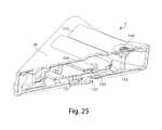
- FIG. 22is a perspective view of the device shown in FIG. 19 with the cover removed and at a different angle than the view shown in FIG. 21 ;
- FIG. 29is an enlarged view of a release element including resistance arms
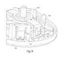
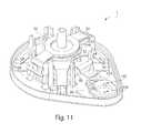
- FIG. 1shows a fluid receiving device 1 that incorporates various aspects of the invention.
- FIG. 1incorporates many of the aspects of the invention, any suitable number of aspects of the invention may be incorporated into a fluid receiving device. Thus, aspects of the invention may be used alone or in any suitable combination with each other.
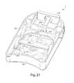
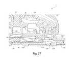
- This illustrative embodimentincludes a cover 20 and a base 100 that are joined together and may cooperate to enclose various parts of the device 1 and support one or more external features, such as a device actuator 10 that is used to cause the device 1 to receive fluid from a subject.
- the base 100 and the cover 20may be formed from or otherwise include Polyester (PCTA or PETG) or other polymers with low gas permeability.
- the vacuum inlet 154is normally closed by a seal 76 , which may be part of the membrane 72 , which also helps to isolate the vacuum source 156 from the opening 130 and other potential outlets for the low pressure in the vacuum source 156 .
- the seal 76is engaged with one of the legs 48 of the retraction actuator 40 (a seal leg 49 ) so that when the retraction actuator 40 is in a compressed, initial state, the seal leg 49 presses the seal 76 into contact with the vacuum inlet 154 so as to close the passage 150 and prevent communication between the vacuum source 156 and the storage chamber 140 .
- the channel 110may be formed, at least in part, by a single component, e.g. an etched substrate or molded unit such as the base 100 .
- the channelcan have any cross-sectional shape, for example, circular, oval, triangular, irregular, square or rectangular (having any aspect ratio), or the like, and can be covered or uncovered (i.e., open to the external environment surrounding the channel).
- the channel 110may be of any length.
- the channel 110can be a simple two-dimensional opening that creates a fluidic coupling between the opening 130 and another vessel such as a vacuum source or a storage vessel.
- the channelmay not have any length at all (e.g., as in a two-dimensional opening).
- at least one portion of the channelcan have a cross-section that is completely enclosed, and/or the entire channel may be completely enclosed along its entire length with the exception of its inlet and outlet.
- Spike 510may be partially hollow and may include a vacuum inlet channel 511 which may help ensure flow between the vacuum source 156 and the dead volume 514 .
- puncturing seal 512 with spike 510effectively opens communication between vacuum source 156 and opening 130 .
- This initial application of vacuum or other relatively low pressure at the area near opening 130may cause skin to be drawn into or nearer to the opening.
- further downward movement of device actuator 10causes actuation ring 540 to contact and actuate deployment actuator 60 .
- actuation of deployment actuator 60may cause the flow activator 90 to at least partially extend from the opening 130 or otherwise move to pierce a subject's skin and cause fluid to be released.
- deployment actuator 60is shown in its post-deployment state and is therefore arranged concave downward away from actuation ring 540 .
- spinner ramp 562Prior to deployment, spinner ramp 562 is held within pre-deployment lockout 556 such that actuation ring 540 on the release element 170 is held at a distance close to the top surface of the deployment actuator 60 . Engagement between spinner ramp 562 and pre-deployment lockout 556 also locks retraction actuator 40 in a compressed, high-energy state.
- the needlesmay be positioned within the array such that no two needles are closer than about 1 mm, about 0.9 mm, about 0.8 mm, about 0.7 mm, about 0.6 mm, about 0.5 mm, about 0.4 mm, about 0.3 mm, about 0.2 mm, about 0.1 mm, about 0.05 mm, about 0.03 mm, about 0.01 mm, etc.
- the needles or microneedlesmay have a maximum penetration into the skin of no more than about 3 mm, no more than about 2 mm, no more than about 1.75 mm, no more than about 1.5 mm, no more than about 1.25 mm, no more than about 1 mm, no more than about 900 microns, no more than about 800 microns, no more than about 750 microns, no more than about 600 microns, no more than about 500 microns, no more than about 400 microns, no more than about 300 microns, no more than about 200 microns, no more than about 175 micrometers, no more than about 150 micrometers, no more than about 125 micrometers, no more than about 100 micrometers, no more than about 75 micrometers, no more than about 50 micrometers, etc.
Landscapes
- Health & Medical Sciences (AREA)
- Life Sciences & Earth Sciences (AREA)
- Engineering & Computer Science (AREA)
- General Health & Medical Sciences (AREA)
- Public Health (AREA)
- Heart & Thoracic Surgery (AREA)
- Medical Informatics (AREA)
- Veterinary Medicine (AREA)
- Biomedical Technology (AREA)
- Animal Behavior & Ethology (AREA)
- Physics & Mathematics (AREA)
- Pathology (AREA)
- Molecular Biology (AREA)
- Surgery (AREA)
- Biophysics (AREA)
- Hematology (AREA)
- Dermatology (AREA)
- Optics & Photonics (AREA)
- Vascular Medicine (AREA)
- Anesthesiology (AREA)
- Pain & Pain Management (AREA)
- Immunology (AREA)
- Primary Health Care (AREA)
- Epidemiology (AREA)
- Emergency Medicine (AREA)
- Manufacturing & Machinery (AREA)
- General Chemical & Material Sciences (AREA)
- Chemical Kinetics & Catalysis (AREA)
- Chemical & Material Sciences (AREA)
- Cardiology (AREA)
- Measurement Of The Respiration, Hearing Ability, Form, And Blood Characteristics Of Living Organisms (AREA)
- Infusion, Injection, And Reservoir Apparatuses (AREA)
- Surgical Instruments (AREA)
- Prostheses (AREA)
Abstract
Description
Claims (43)
Priority Applications (5)
| Application Number | Priority Date | Filing Date | Title |
|---|---|---|---|
| US13/456,570US8827971B2 (en) | 2011-04-29 | 2012-04-26 | Delivering and/or receiving fluids |
| US13/680,351US8821412B2 (en) | 2009-03-02 | 2012-11-19 | Delivering and/or receiving fluids |
| US14/328,892US9730624B2 (en) | 2009-03-02 | 2014-07-11 | Delivering and/or receiving fluids |
| US15/634,354US10799166B2 (en) | 2009-03-02 | 2017-06-27 | Delivering and/or receiving fluids |
| US17/014,022US20220071534A9 (en) | 2009-03-02 | 2020-09-08 | Delivering and/or receiving fluids |
Applications Claiming Priority (2)
| Application Number | Priority Date | Filing Date | Title |
|---|---|---|---|
| US201161480977P | 2011-04-29 | 2011-04-29 | |
| US13/456,570US8827971B2 (en) | 2011-04-29 | 2012-04-26 | Delivering and/or receiving fluids |
Related Parent Applications (1)
| Application Number | Title | Priority Date | Filing Date |
|---|---|---|---|
| US13/456,394Continuation-In-PartUS9295417B2 (en) | 2009-03-02 | 2012-04-26 | Systems and methods for collecting fluid from a subject |
Related Child Applications (2)
| Application Number | Title | Priority Date | Filing Date |
|---|---|---|---|
| PCT/US2011/047565Continuation-In-PartWO2012021792A2 (en) | 2009-03-02 | 2011-08-12 | Clinical and/or consumer techniques and devices |
| US13/680,351Continuation-In-PartUS8821412B2 (en) | 2009-03-02 | 2012-11-19 | Delivering and/or receiving fluids |
Publications (3)
| Publication Number | Publication Date |
|---|---|
| US20120277696A1 US20120277696A1 (en) | 2012-11-01 |
| US20130138058A9 US20130138058A9 (en) | 2013-05-30 |
| US8827971B2true US8827971B2 (en) | 2014-09-09 |
Family
ID=46085182
Family Applications (5)
| Application Number | Title | Priority Date | Filing Date |
|---|---|---|---|
| US13/456,570Active2032-04-30US8827971B2 (en) | 2009-03-02 | 2012-04-26 | Delivering and/or receiving fluids |
| US13/680,351ActiveUS8821412B2 (en) | 2009-03-02 | 2012-11-19 | Delivering and/or receiving fluids |
| US14/328,892Active2030-04-10US9730624B2 (en) | 2009-03-02 | 2014-07-11 | Delivering and/or receiving fluids |
| US15/634,354Active2030-10-12US10799166B2 (en) | 2009-03-02 | 2017-06-27 | Delivering and/or receiving fluids |
| US18/333,656PendingUS20230338639A1 (en) | 2011-04-29 | 2023-06-13 | Delivering and/or receiving material with respect to a subject surface |
Family Applications After (4)
| Application Number | Title | Priority Date | Filing Date |
|---|---|---|---|
| US13/680,351ActiveUS8821412B2 (en) | 2009-03-02 | 2012-11-19 | Delivering and/or receiving fluids |
| US14/328,892Active2030-04-10US9730624B2 (en) | 2009-03-02 | 2014-07-11 | Delivering and/or receiving fluids |
| US15/634,354Active2030-10-12US10799166B2 (en) | 2009-03-02 | 2017-06-27 | Delivering and/or receiving fluids |
| US18/333,656PendingUS20230338639A1 (en) | 2011-04-29 | 2023-06-13 | Delivering and/or receiving material with respect to a subject surface |
Country Status (10)
| Country | Link |
|---|---|
| US (5) | US8827971B2 (en) |
| EP (2) | EP3087919B2 (en) |
| JP (6) | JP6121400B2 (en) |
| KR (2) | KR102013466B1 (en) |
| CN (1) | CN103874460B (en) |
| AU (6) | AU2012249692A1 (en) |
| BR (1) | BR112013027351B1 (en) |
| CA (1) | CA2833275C (en) |
| ES (1) | ES2597081T3 (en) |
| WO (1) | WO2012149143A1 (en) |
Cited By (34)
| Publication number | Priority date | Publication date | Assignee | Title |
|---|---|---|---|---|
| US9033898B2 (en) | 2010-06-23 | 2015-05-19 | Seventh Sense Biosystems, Inc. | Sampling devices and methods involving relatively little pain |
| US9041541B2 (en) | 2010-01-28 | 2015-05-26 | Seventh Sense Biosystems, Inc. | Monitoring or feedback systems and methods |
| US9113836B2 (en) | 2009-03-02 | 2015-08-25 | Seventh Sense Biosystems, Inc. | Devices and techniques associated with diagnostics, therapies, and other applications, including skin-associated applications |
| US9119578B2 (en) | 2011-04-29 | 2015-09-01 | Seventh Sense Biosystems, Inc. | Plasma or serum production and removal of fluids under reduced pressure |
| US9295417B2 (en) | 2011-04-29 | 2016-03-29 | Seventh Sense Biosystems, Inc. | Systems and methods for collecting fluid from a subject |
| US9381680B2 (en) | 2008-05-21 | 2016-07-05 | Theraject, Inc. | Method of manufacturing solid solution perforator patches and uses thereof |
| US9730624B2 (en) | 2009-03-02 | 2017-08-15 | Seventh Sense Biosystems, Inc. | Delivering and/or receiving fluids |
| US10371606B2 (en) | 2015-07-21 | 2019-08-06 | Theraos IP Company, LLC | Bodily fluid sample collection and transport |
| US10543310B2 (en) | 2011-12-19 | 2020-01-28 | Seventh Sense Biosystems, Inc. | Delivering and/or receiving material with respect to a subject surface |
| US10542922B2 (en) | 2013-03-26 | 2020-01-28 | The Trustees Of Columbia University In The City Of New York | Fluid extraction and drug delivery system and methods using microneedles |
| US10562022B2 (en) | 2012-12-05 | 2020-02-18 | Boston Microfluidics, Inc. | Mechanically actuated vacuum controlled fluid collection |
| US10638963B2 (en) | 2017-01-10 | 2020-05-05 | Drawbridge Health, Inc. | Devices, systems, and methods for sample collection |
| US10925532B2 (en) | 2015-08-06 | 2021-02-23 | Becton, Dickinson And Company | Biological fluid collection device and biological fluid collection system |
| US11177029B2 (en) | 2010-08-13 | 2021-11-16 | Yourbio Health, Inc. | Systems and techniques for monitoring subjects |
| US11202895B2 (en) | 2010-07-26 | 2021-12-21 | Yourbio Health, Inc. | Rapid delivery and/or receiving of fluids |
| US11266337B2 (en) | 2015-09-09 | 2022-03-08 | Drawbridge Health, Inc. | Systems, methods, and devices for sample collection, stabilization and preservation |
| US11358139B2 (en) | 2017-10-27 | 2022-06-14 | Weavr Health Corp. | Pinch to open sample collection device |
| US11360076B2 (en) | 2012-03-30 | 2022-06-14 | Weavr Health Corp. | Methods and systems to collect a biological sample |
| US11358138B2 (en) | 2013-07-19 | 2022-06-14 | Boston Microfluidics Inc. | Fluid sample collection device |
| US11478175B1 (en) | 2021-10-20 | 2022-10-25 | Paulus Holdings Limited | Devices for collecting capillary blood and methods for same |
| US11484877B2 (en) | 2018-05-29 | 2022-11-01 | Weavr Health Corp. | Blood metering device with desiccant and support for storage media and inlay with flange |
| US11490839B2 (en) | 2018-10-23 | 2022-11-08 | Weavr Health Corp. | Funnel with extension tube to augment blood collection device |
| US11772097B2 (en) | 2018-10-19 | 2023-10-03 | Renegadexbio, Pbc | Simultaneous spot test and storage of blood samples |
| US11877848B2 (en) | 2021-11-08 | 2024-01-23 | Satio, Inc. | Dermal patch for collecting a physiological sample |
| US11957465B2 (en) | 2022-08-23 | 2024-04-16 | Reddrop Dx, Inc. | Accelerated ergonomic collection of capillary blood |
| US11964121B2 (en) | 2021-10-13 | 2024-04-23 | Satio, Inc. | Mono dose dermal patch for pharmaceutical delivery |
| US12023156B2 (en) | 2021-10-13 | 2024-07-02 | Satio, Inc. | Dermal patch for collecting a physiological sample |
| US12029562B2 (en) | 2021-04-14 | 2024-07-09 | Satio, Inc. | Dermal patch system |
| US12048543B2 (en) | 2021-11-08 | 2024-07-30 | Satio, Inc. | Dermal patch for collecting a physiological sample with removable vial |
| US12053284B2 (en) | 2021-11-08 | 2024-08-06 | Satio, Inc. | Dermal patch for collecting a physiological sample |
| US12121353B2 (en) | 2010-11-09 | 2024-10-22 | Yourbio Health, Inc. | Systems and interfaces for blood sampling |
| US12178979B2 (en) | 2021-10-13 | 2024-12-31 | Satio, Inc. | Dermal patch for delivering a pharmaceutical |
| US12214346B2 (en) | 2021-10-13 | 2025-02-04 | Satio, Inc. | Dermal patch with a diagnostic test strip |
| US12440133B2 (en) | 2024-03-29 | 2025-10-14 | Satio, Inc. | Dermal patch for collecting a physiological sample |
Families Citing this family (71)
| Publication number | Priority date | Publication date | Assignee | Title |
|---|---|---|---|---|
| GB0402131D0 (en) | 2004-01-30 | 2004-03-03 | Isis Innovation | Delivery method |
| US20110105952A1 (en)* | 2009-10-30 | 2011-05-05 | Seventh Sense Biosystems, Inc. | Relatively small devices applied to the skin, modular systems, and methods of use thereof |
| WO2011053796A2 (en)* | 2009-10-30 | 2011-05-05 | Seventh Sense Biosystems, Inc. | Systems and methods for treating, sanitizing, and/or shielding the skin or devices applied to the skin |
| US20120016308A1 (en) | 2010-07-16 | 2012-01-19 | Seventh Sense Biosystems, Inc. | Low-pressure packaging for fluid devices |
| EP2765927B1 (en) | 2011-10-12 | 2021-02-24 | Vaxxas Pty Limited | Delivery device |
| US20130211289A1 (en) | 2012-01-25 | 2013-08-15 | Tasso, Inc. | Handheld Device for Drawing, Collecting, and Analyzing Bodily Fluid |
| AU2014209951A1 (en)* | 2013-01-25 | 2015-08-27 | Youmedical Brands B.V. | Device for non-surgical cold treatment of disorders |
| ES2832756T3 (en)* | 2013-04-15 | 2021-06-11 | Becton Dickinson Co | Biological fluid sampling device |
| JP6240308B2 (en)* | 2013-04-15 | 2017-11-29 | ベクトン・ディキンソン・アンド・カンパニーBecton, Dickinson And Company | Biological fluid separation device and biological fluid separation and inspection system |
| JP6247380B2 (en) | 2013-04-15 | 2017-12-13 | ベクトン・ディキンソン・アンド・カンパニーBecton, Dickinson And Company | Blood collection and transportation device |
| US10194851B2 (en) | 2013-04-15 | 2019-02-05 | Becton, Dickinson And Company | Blood sampling transfer device and blood separation and testing system |
| BR112015026222B1 (en) | 2013-04-15 | 2022-05-17 | Becton, Dickinson And Company | Biological fluid sample collection device and biological fluid examination system |
| EP2986381B1 (en)* | 2013-04-15 | 2018-08-01 | Becton, Dickinson and Company | Biological fluid collection device and biological fluid separation and testing system |
| WO2014172235A1 (en)* | 2013-04-15 | 2014-10-23 | Becton, Dickinson And Company | Biological fluid collection device and biological fluid separation system |
| CA2909263C (en) | 2013-04-15 | 2020-01-28 | Becton, Dickinson And Company | Biological fluid sampling transfer device and biological fluid separation and testing system |
| ES2828508T3 (en) | 2013-04-15 | 2021-05-26 | Becton Dickinson Co | Biological fluid separation device and biological fluid separation and testing system |
| US9380972B2 (en) | 2013-04-15 | 2016-07-05 | Becton, Dickinson And Company | Biological fluid collection device and biological fluid collection and testing system |
| EP2986218B1 (en) | 2013-04-15 | 2017-12-20 | Becton, Dickinson and Company | Biological fluid collection device and biological fluid separation and testing system |
| WO2014172233A1 (en)* | 2013-04-15 | 2014-10-23 | Becton, Dickinson And Company | Biological fluid transfer device and biological fluid sampling system |
| US10080516B2 (en) | 2013-04-15 | 2018-09-25 | Becton, Dickinson And Company | Biological fluid collection device and biological fluid separation and testing system |
| JP6568843B2 (en) | 2013-04-15 | 2019-08-28 | ベクトン・ディキンソン・アンド・カンパニーBecton, Dickinson And Company | Body fluid sampling device and body fluid sampling and collection assembly |
| JP6193474B2 (en) | 2013-04-15 | 2017-09-06 | ベクトン・ディキンソン・アンド・カンパニーBecton, Dickinson And Company | Biological fluid collection and transfer device and biological fluid separation and inspection system |
| WO2015009970A1 (en) | 2013-07-18 | 2015-01-22 | Erythron Llc | Spectroscopic measurements with parallel array detector |
| WO2015112575A1 (en)* | 2014-01-22 | 2015-07-30 | The Board Of Regents Of The University Of Nebraska | Gastrointestinal sensor implantation system |
| GB201401133D0 (en)* | 2014-01-23 | 2014-03-12 | Renephra Ltd | Fluid extraction device, applicator device and associated methods |
| US20170007215A1 (en)* | 2014-01-30 | 2017-01-12 | SALVME, Inc. | System for saliva collection |
| US20150338338A1 (en) | 2014-02-28 | 2015-11-26 | Erythron, Llc | Method and Apparatus for Determining Markers of Health by Analysis of Blood |
| CN106999120B (en)* | 2014-08-01 | 2021-05-14 | 塔索公司 | Devices, systems, and methods for gravity-enhanced microfluidic collection, handling, and delivery of liquids |
| US11147954B2 (en)* | 2015-02-02 | 2021-10-19 | Vaxxas Pty Limited | Microprojection array applicator and method |
| EP3282937A4 (en) | 2015-04-14 | 2018-11-21 | Nueon Inc. | Method and apparatus for determining markers of health by analysis of blood |
| CN113181477B (en) | 2015-06-04 | 2023-07-14 | 麦迪麦珀医疗工程有限公司 | Cartridge insertion for drug delivery device |
| US11278225B2 (en)* | 2015-08-12 | 2022-03-22 | University Of Tasmania | Liquid collection device |
| WO2017045031A1 (en) | 2015-09-18 | 2017-03-23 | Vaxxas Pty Limited | Microprojection arrays with microprojections having large surface area profiles |
| EP3355981A4 (en) | 2015-09-28 | 2019-05-22 | Vaxxas Pty Limited | MICROAILLY NETWORK HAVING IMPROVED SKIN PENETRATION PROPERTIES AND ASSOCIATED METHODS |
| CA3009328C (en)* | 2015-12-21 | 2024-03-05 | Tasso, Inc. | Devices, systems and methods for actuation and retraction in fluid collection |
| WO2017165403A1 (en) | 2016-03-21 | 2017-09-28 | Nueon Inc. | Porous mesh spectrometry methods and apparatus |
| US10765369B2 (en) | 2016-04-08 | 2020-09-08 | Medtronic Minimed, Inc. | Analyte sensor |
| US20170290535A1 (en)* | 2016-04-08 | 2017-10-12 | Medtronic Minimed, Inc. | Analyte sensor with indicators |
| US10765348B2 (en)* | 2016-04-08 | 2020-09-08 | Medtronic Minimed, Inc. | Sensor and transmitter product |
| US10631787B2 (en) | 2016-04-08 | 2020-04-28 | Medtronic Minimed, Inc. | Sensor and transmitter product |
| US12419547B2 (en) | 2016-04-08 | 2025-09-23 | Medtronic Minimed, Inc. | Sensor and transmitter product |
| EP3711670B1 (en)* | 2016-05-04 | 2022-03-16 | midge medical GmbH | Body fluid extraction device |
| WO2018022535A1 (en)* | 2016-07-29 | 2018-02-01 | Seventh Sense Biosystems, Inc. | Device for receiving bodily fluid from a subject |
| US10585021B2 (en) | 2016-08-11 | 2020-03-10 | Instrumentation Laboratory Company | Dual chamber reagent mixing container |
| US10456787B2 (en)* | 2016-08-11 | 2019-10-29 | Instrumentation Laboratory Company | Reagent component dispensing caps for reagent containers used in automated clinical analyzers |
| CN109069077B (en)* | 2016-08-26 | 2021-03-02 | 泰尔茂株式会社 | Medical instrument and fixture |
| WO2018085699A1 (en) | 2016-11-04 | 2018-05-11 | Nueon Inc. | Combination blood lancet and analyzer |
| US20180256086A1 (en)* | 2017-03-08 | 2018-09-13 | National Technology & Engineering Solutions Of Sandia, Llc | Microneedle Device for Interstitial Fluid Extraction |
| WO2018176102A1 (en) | 2017-03-31 | 2018-10-04 | Vaxxas Pty Limited | Device and method for coating surfaces |
| WO2018227246A1 (en) | 2017-06-13 | 2018-12-20 | Vaxxas Pty Limited | Quality control of substrate coatings |
| CA3071680A1 (en)* | 2017-08-04 | 2019-02-07 | Vaxxas Pty Limited | Compact high mechanical energy storage and low trigger force actuator for the delivery of microprojection array patches (map) |
| CN111163817B (en)* | 2017-09-21 | 2022-04-01 | 西部制药服务有限公司(以色列) | Needle insertion mechanism for syringe |
| CN107934896B (en)* | 2017-11-01 | 2020-09-04 | 九牧厨卫股份有限公司 | Urine conveying device |
| TWI653968B (en)* | 2017-11-20 | 2019-03-21 | 研能科技股份有限公司 | Blood glucose detecting device |
| JP7402799B2 (en) | 2017-12-22 | 2023-12-21 | ウェスト ファーマ サービシーズ イスラエル リミテッド | Syringes available with different cartridge sizes |
| CN108175421B (en)* | 2017-12-30 | 2019-07-23 | 枣庄市妇幼保健院 | High-efficiency and energy-saving blood collection and storage test tubes |
| IT201800004247A1 (en)* | 2018-04-05 | 2019-10-05 | OPTICAL SENSOR DEVICE FOR FLUID SUBSTANCES | |
| CA3098664A1 (en)* | 2018-05-01 | 2019-11-07 | Becton, Dickinson And Company | Biological fluid micro-sample management device |
| JP7460607B2 (en) | 2018-09-14 | 2024-04-02 | タッソ インコーポレイテッド | Body fluid collection devices and related methods |
| JP2020161569A (en)* | 2019-03-25 | 2020-10-01 | 株式会社東芝 | Housing, electronic device, method for manufacturing housing, and method for manufacturing electronic device |
| AU2020265824B2 (en)* | 2019-05-02 | 2025-08-14 | Yourbio Health, Inc. | Devices and methods for receiving fluids |
| ES2940212T3 (en)* | 2019-11-13 | 2023-05-04 | Loop Medical Sa | Sample collection device for extracting and collecting a sample of a fluid from a user |
| EP4142589A1 (en) | 2020-05-01 | 2023-03-08 | YourBio Health, Inc. | Vacuum generation devices and methods |
| RU2737998C1 (en)* | 2020-06-19 | 2020-12-07 | Никита Сергеевич Комов | Blood sampling device |
| RU201119U1 (en)* | 2020-06-19 | 2020-11-27 | Никита Сергеевич Комов | Blood collection device |
| EP4253953A4 (en)* | 2020-11-25 | 2024-09-25 | Provigate Inc. | MEDIUM FOR SEPARATION AND STORAGE OF BLOOD PLASMA OR SERUM, METHOD FOR PRODUCING SAME, DEVICE, KIT AND METHOD FOR MEASURING GLYCOSYLATED PROTEIN |
| EP4277527A1 (en)* | 2021-01-12 | 2023-11-22 | Anvajo GmbH | Sample-receiving device |
| AU2022227019A1 (en)* | 2021-02-26 | 2023-08-31 | Tasso, Inc. | Bodily fluid collection devices and related methods |
| CA3219530A1 (en)* | 2021-05-19 | 2022-11-24 | Namal NAWANA | Self-contained dermal patch for blood analysis |
| CN117653102A (en)* | 2022-08-31 | 2024-03-08 | 深圳华大智造科技股份有限公司 | Sample collection device and method |
| CN116509458B (en)* | 2023-03-13 | 2024-07-12 | 深圳大学 | Device for rapidly extracting and storing tissue fluid under negative pressure based on microneedle array |
Citations (431)
| Publication number | Priority date | Publication date | Assignee | Title |
|---|---|---|---|---|
| US3060429A (en) | 1958-05-16 | 1962-10-23 | Certificate of correction | |
| US3339546A (en) | 1963-12-13 | 1967-09-05 | Squibb & Sons Inc | Bandage for adhering to moist surfaces |
| US3551554A (en) | 1968-08-16 | 1970-12-29 | Crown Zellerbach Corp | Enhancing tissue penetration of physiologically active agents with dmso |
| US3711602A (en) | 1970-10-30 | 1973-01-16 | Crown Zellerbach Corp | Compositions for topical application for enhancing tissue penetration of physiologically active agents with dmso |
| US3711606A (en) | 1970-09-02 | 1973-01-16 | Crown Zellerbach Corp | Enhancing tissue penetration of physiologically active steroidal agents with dmso |
| US3740421A (en) | 1966-09-19 | 1973-06-19 | Basf Wyandotte Corp | Polyoxyethylene-polyoxypropylene aqueous gels |
| US3908657A (en) | 1973-01-15 | 1975-09-30 | Univ Johns Hopkins | System for continuous withdrawal of blood |
| US4103684A (en) | 1976-12-30 | 1978-08-01 | Aaron Ismach | Hydraulically powered hypodermic injector with adapters for reducing and increasing fluid injection force |
| US4150744A (en) | 1976-02-27 | 1979-04-24 | Smith & Nephew Pharmaceuticals Ltd. | Packaging |
| US4253460A (en) | 1979-07-27 | 1981-03-03 | E. R. Squibb & Sons, Inc. | Ostomy adhesive |
| EP0043738A2 (en) | 1980-07-09 | 1982-01-13 | THE PROCTER & GAMBLE COMPANY | Penetrating topical pharmaceutical compositions |
| US4329999A (en) | 1980-03-03 | 1982-05-18 | Michael Phillips | Patient attached patch and method of making |
| EP0115388A1 (en) | 1983-01-13 | 1984-08-08 | Genetics International, Inc. | Blood sampling instrument |
| GB2153223A (en) | 1984-02-01 | 1985-08-21 | Nitto Electric Ind Co | Composition for percutaneously administering metoclopramide |
| US4537776A (en) | 1983-06-21 | 1985-08-27 | The Procter & Gamble Company | Penetrating topical pharmaceutical compositions containing N-(2-hydroxyethyl) pyrrolidone |
| US4553552A (en) | 1984-02-21 | 1985-11-19 | Valdespino Joseph M | Hemodialysis meter |
| US4557943A (en) | 1983-10-31 | 1985-12-10 | Advanced Semiconductor Materials America, Inc. | Metal-silicide deposition using plasma-enhanced chemical vapor deposition |
| US4615697A (en) | 1983-11-14 | 1986-10-07 | Bio-Mimetics, Inc. | Bioadhesive compositions and methods of treatment therewith |
| US4621268A (en) | 1984-02-08 | 1986-11-04 | Keeling Michael R | Fluid application method and apparatus |
| US4637403A (en) | 1985-04-08 | 1987-01-20 | Garid, Inc. | Glucose medical monitoring system |
| US4696309A (en) | 1983-04-12 | 1987-09-29 | Eberhart Stephan | Portable apparatus for taking blood samples |
| US4706676A (en) | 1985-02-11 | 1987-11-17 | The United States Of America As Represented By The Secretary Of The Army | Dermal substance collection device |
| EP0250693A1 (en) | 1986-06-20 | 1988-01-07 | A. Menarini S.a.S. | Portable device for the instantaneous drawing of blood |
| US4740365A (en) | 1984-04-09 | 1988-04-26 | Toyo Boseki Kabushiki Kaisha | Sustained-release preparation applicable to mucous membrane in oral cavity |
| US4756314A (en) | 1985-10-28 | 1988-07-12 | Alza Corporation | Sweat collection patch |
| US4764378A (en) | 1986-02-10 | 1988-08-16 | Zetachron, Inc. | Buccal drug dosage form |
| US4772470A (en) | 1985-04-27 | 1988-09-20 | Nitto Electric Industrial Co., Ltd. | Oral bandage and oral preparations |
| US4820720A (en) | 1987-08-24 | 1989-04-11 | Alza Corporation | Transdermal drug composition with dual permeation enhancers |
| US4821733A (en) | 1987-08-18 | 1989-04-18 | Dermal Systems International | Transdermal detection system |
| US4855298A (en) | 1986-11-21 | 1989-08-08 | Tanabe Seiyaku Co., Ltd. | 6-Halo-1,2,3,4-tetrahydroquinazoline-4-spiro-4-imidazolidine-2,2'5'-triones useful for the treatment and prophylaxis of diabetic complications |
| US4863970A (en) | 1986-11-14 | 1989-09-05 | Theratech, Inc. | Penetration enhancement with binary system of oleic acid, oleins, and oleyl alcohol with lower alcohols |
| US4908404A (en) | 1988-08-22 | 1990-03-13 | Biopolymers, Inc. | Synthetic amino acid-and/or peptide-containing graft copolymers |
| EP0365196A2 (en) | 1988-10-12 | 1990-04-25 | Thorne, Smith, Astill Technologies, Inc. | Medical droplet whole blood and like monitoring |
| US4957108A (en) | 1988-09-08 | 1990-09-18 | Sudor Partners | Method and apparatus for determination of chemical species in body fluid |
| US4973468A (en) | 1989-03-22 | 1990-11-27 | Cygnus Research Corporation | Skin permeation enhancer compositions |
| US5006342A (en) | 1986-12-22 | 1991-04-09 | Cygnus Corporation | Resilient transdermal drug delivery device |
| US5015677A (en) | 1986-04-25 | 1991-05-14 | Bio-Polymers, Inc. | Adhesives derived from bioadhesive polyphenolic proteins |
| US5036861A (en) | 1990-01-11 | 1991-08-06 | Sembrowich Walter L | Method and apparatus for non-invasively monitoring plasma glucose levels |
| US5054499A (en) | 1989-03-27 | 1991-10-08 | Swierczek Remi D | Disposable skin perforator and blood testing device |
| US5076273A (en) | 1988-09-08 | 1991-12-31 | Sudor Partners | Method and apparatus for determination of chemical species in body fluid |
| US5161532A (en) | 1990-04-19 | 1992-11-10 | Teknekron Sensor Development Corporation | Integral interstitial fluid sensor |
| US5174291A (en) | 1987-10-05 | 1992-12-29 | Rijksuniversiteit Te Groningen | Process for using a measuring cell assembly for glucose determination |
| US5213568A (en) | 1990-03-30 | 1993-05-25 | Medtronic Inc. | Activity controlled electrotransport drug delivery device |
| US5231993A (en) | 1991-11-20 | 1993-08-03 | Habley Medical Technology Corporation | Blood sampler and component tester with guide member |
| EP0555554A1 (en) | 1992-02-13 | 1993-08-18 | Kabushiki Kaisya Advance | Simple blood sampling device |
| US5279294A (en) | 1985-04-08 | 1994-01-18 | Cascade Medical, Inc. | Medical diagnostic system |
| US5402798A (en) | 1991-07-18 | 1995-04-04 | Swierczek; Remi | Disposable skin perforator and blood testing device |
| WO1995010223A2 (en) | 1993-10-13 | 1995-04-20 | Inomet, Inc. | Interstitial fluid collection and constituent measurement |
| WO1995015783A1 (en) | 1993-12-07 | 1995-06-15 | Principal Ab | Device for use in transdermal perfusion procedures |
| US5438984A (en) | 1988-09-08 | 1995-08-08 | Sudor Partners | Apparatus and method for the collection of analytes on a dermal patch |
| US5441048A (en) | 1988-09-08 | 1995-08-15 | Sudor Partners | Method and apparatus for determination of chemical species in perspiration |
| US5441490A (en) | 1991-01-09 | 1995-08-15 | Principal Ab | Transdermal perfusion of fluids |
| US5443080A (en) | 1993-12-22 | 1995-08-22 | Americate Transtech, Inc. | Integrated system for biological fluid constituent analysis |
| US5445611A (en) | 1993-12-08 | 1995-08-29 | Non-Invasive Monitoring Company (Nimco) | Enhancement of transdermal delivery with ultrasound and chemical enhancers |
| US5458140A (en) | 1993-11-15 | 1995-10-17 | Non-Invasive Monitoring Company (Nimco) | Enhancement of transdermal monitoring applications with ultrasound and chemical enhancers |
| US5505212A (en) | 1991-06-21 | 1996-04-09 | Novo Nordisk A/S | Blood sampler |
| US5507288A (en) | 1994-05-05 | 1996-04-16 | Boehringer Mannheim Gmbh | Analytical system for monitoring a substance to be analyzed in patient-blood |
| US5520727A (en) | 1993-08-16 | 1996-05-28 | The Regents Of University Of California | Aqueous algal-based phenolic type adhesives and glues |
| US5529581A (en) | 1994-05-17 | 1996-06-25 | International Technidyne Corporation | Lancet device for creating a skin incision |
| US5560543A (en) | 1994-09-19 | 1996-10-01 | Board Of Regents, The University Of Texas System | Heat-resistant broad-bandwidth liquid droplet generators |
| US5574134A (en) | 1989-07-11 | 1996-11-12 | University Of Delaware | Polypeptide monomers, linearly extended and/or crosslinked forms thereof, and applications thereof |
| US5580794A (en) | 1993-08-24 | 1996-12-03 | Metrika Laboratories, Inc. | Disposable electronic assay device |
| WO1997008987A1 (en) | 1995-09-08 | 1997-03-13 | Integ, Inc. | Enhanced interstitial fluid collection |
| WO1997010745A1 (en) | 1995-09-08 | 1997-03-27 | Integ, Inc. | Body fluid sampler |
| US5636640A (en) | 1995-02-06 | 1997-06-10 | Volunteers For Medical Engineering | Liquid sampling and test apparatus |
| US5662127A (en) | 1996-01-17 | 1997-09-02 | Bio-Plas, Inc. | Self-contained blood withdrawal apparatus and method |
| WO1997034587A2 (en) | 1996-03-20 | 1997-09-25 | Svedman Paul | Transdermal device |
| US5676144A (en) | 1988-09-08 | 1997-10-14 | Sudor Partners | Method and apparatus for determination of chemical species in body fluid |
| US5682233A (en) | 1995-09-08 | 1997-10-28 | Integ, Inc. | Interstitial fluid sampler |
| US5680872A (en) | 1993-08-10 | 1997-10-28 | Kabushiki Kaisya Advance | Simple blood-collecting device |
| US5685875A (en) | 1992-09-25 | 1997-11-11 | Cobe Laboratories, Inc. | Fluid sampling device for closed collection systems |
| WO1997048442A1 (en) | 1996-06-18 | 1997-12-24 | Alza Corporation | Device for enhancing transdermal agent delivery or sampling |
| US5714390A (en) | 1996-10-15 | 1998-02-03 | Bio-Tech Imaging, Inc. | Cartridge test system for the collection and testing of blood in a single step |
| US5741138A (en) | 1996-08-12 | 1998-04-21 | The Procter & Gamble Company | Oral compositions |
| WO1998024366A2 (en) | 1996-12-06 | 1998-06-11 | Abbott Laboratories | Method and apparatus for obtaining blood for diagnostic tests |
| US5800420A (en) | 1994-11-04 | 1998-09-01 | Elan Medical Technologies Limited | Analyte-controlled liquid delivery device and analyte monitor |
| US5811108A (en) | 1995-06-26 | 1998-09-22 | Goeringer; Leslie A. | Sun blocking tattoo sticker |
| US5813614A (en) | 1994-03-29 | 1998-09-29 | Electrosols, Ltd. | Dispensing device |
| US5817012A (en) | 1988-09-08 | 1998-10-06 | Sudormed, Inc. | Method of determining an analyte |
| US5857983A (en) | 1996-05-17 | 1999-01-12 | Mercury Diagnostics, Inc. | Methods and apparatus for sampling body fluid |
| US5858188A (en) | 1990-02-28 | 1999-01-12 | Aclara Biosciences, Inc. | Acrylic microchannels and their use in electrophoretic applications |
| US5873900A (en) | 1995-09-13 | 1999-02-23 | Empi, Inc. | Electronic pain feedback system and method |
| US5876675A (en) | 1997-08-05 | 1999-03-02 | Caliper Technologies Corp. | Microfluidic devices and systems |
| US5879311A (en) | 1996-05-17 | 1999-03-09 | Mercury Diagnostics, Inc. | Body fluid sampling device and methods of use |
| US5885211A (en) | 1993-11-15 | 1999-03-23 | Spectrix, Inc. | Microporation of human skin for monitoring the concentration of an analyte |
| US5891053A (en) | 1995-05-25 | 1999-04-06 | Kabushiki Kaisya Advance | Blood-collecting device |
| WO1999027852A1 (en) | 1997-12-02 | 1999-06-10 | Abbott Laboratories | Method and apparatus for obtaining interstitial fluid for diagnostic tests |
| CN1222334A (en) | 1998-01-04 | 1999-07-14 | 山东龙冠医疗用品有限公司 | Automatic hemostix |
| US5951493A (en) | 1997-05-16 | 1999-09-14 | Mercury Diagnostics, Inc. | Methods and apparatus for expressing body fluid from an incision |
| US5951492A (en) | 1996-05-17 | 1999-09-14 | Mercury Diagnostics, Inc. | Methods and apparatus for sampling and analyzing body fluid |
| US5955096A (en) | 1996-06-25 | 1999-09-21 | Brown University Research Foundation | Methods and compositions for enhancing the bioadhesive properties of polymers using organic excipients |
| US5963136A (en) | 1998-07-15 | 1999-10-05 | O'brien; Charles Terrence | Interactive prescription compliance and life safety system |
| US5964718A (en) | 1997-11-21 | 1999-10-12 | Mercury Diagnostics, Inc. | Body fluid sampling device |
| US5985312A (en) | 1996-01-26 | 1999-11-16 | Brown University Research Foundation | Methods and compositions for enhancing the bioadhesive properties of polymers |
| US5998588A (en) | 1995-09-01 | 1999-12-07 | University Of Washington | Interactive molecular conjugates |
| US6007845A (en) | 1994-07-22 | 1999-12-28 | Massachusetts Institute Of Technology | Nanoparticles and microparticles of non-linear hydrophilic-hydrophobic multiblock copolymers |
| US6015392A (en) | 1996-05-17 | 2000-01-18 | Mercury Diagnostics, Inc. | Apparatus for sampling body fluid |
| US6044303A (en) | 1995-09-13 | 2000-03-28 | Empi Corp. | TENS device with electronic pain intensity scale |
| US6048337A (en) | 1992-01-07 | 2000-04-11 | Principal Ab | Transdermal perfusion of fluids |
| US6050988A (en) | 1997-12-11 | 2000-04-18 | Alza Corporation | Device for enhancing transdermal agent flux |
| DE19833868A1 (en) | 1997-05-23 | 2000-05-04 | Wagner Wolfgang | Instrument to puncture skin to draw drop of blood for medical analysis has a suction cup with a suction pump to lie on the skin with a test strip which immediately absorbs the blood from the prick |
| US6063029A (en) | 1992-12-07 | 2000-05-16 | Hisamitsu Pharmaceutical Co., Inc. | Diagnostic patch and method for diagnosis using the same |
| US6063039A (en) | 1996-12-06 | 2000-05-16 | Abbott Laboratories | Method and apparatus for obtaining blood for diagnostic tests |
| US6063365A (en) | 1998-09-10 | 2000-05-16 | International Flavors & Fragrances Inc. | Application of film forming technology to fragrance control release systems; and resultant fragrance control release systems |
| WO2000035530A1 (en) | 1998-12-18 | 2000-06-22 | Minimed Inc. | Insertion sets with micro-piercing members for use with medical devices and methods of using the same |
| WO2000035357A1 (en) | 1998-12-18 | 2000-06-22 | Sontra Medical, Inc. | Methods and apparatus for enhancement of transdermal transport |
| US6083196A (en) | 1997-12-11 | 2000-07-04 | Alza Corporation | Device for enhancing transdermal agent flux |
| US6091975A (en) | 1998-04-01 | 2000-07-18 | Alza Corporation | Minimally invasive detecting device |
| US6099484A (en) | 1996-05-17 | 2000-08-08 | Amira Medical | Methods and apparatus for sampling and analyzing body fluid |
| US6107102A (en) | 1995-06-07 | 2000-08-22 | Regents Of The University Of California | Therapeutic microdevices and methods of making and using same |
| US6126899A (en) | 1996-04-03 | 2000-10-03 | The Perkins-Elmer Corporation | Device for multiple analyte detection |
| US6132702A (en) | 1998-02-27 | 2000-10-17 | The Procter & Gamble Company | Oral care compositions comprising chlorite and methods |
| US6132449A (en) | 1999-03-08 | 2000-10-17 | Agilent Technologies, Inc. | Extraction and transportation of blood for analysis |
| US6152942A (en) | 1999-06-14 | 2000-11-28 | Bayer Corporation | Vacuum assisted lancing device |
| WO2000074763A2 (en) | 1999-06-04 | 2000-12-14 | Georgia Tech Research Corporation | Devices and methods for enhanced microneedle penetration of biological barriers |
| US6162639A (en) | 1997-12-19 | 2000-12-19 | Amira Medical | Embossed test strip system |
| US6190315B1 (en) | 1998-01-08 | 2001-02-20 | Sontra Medical, Inc. | Sonophoretic enhanced transdermal transport |
| US6192890B1 (en) | 1998-03-31 | 2001-02-27 | David H Levy | Changeable tattoos |
| US6228100B1 (en) | 1999-10-25 | 2001-05-08 | Steven Schraga | Multi-use lancet device |
| US6234990B1 (en) | 1996-06-28 | 2001-05-22 | Sontra Medical, Inc. | Ultrasound enhancement of transdermal transport |
| US6235313B1 (en) | 1992-04-24 | 2001-05-22 | Brown University Research Foundation | Bioadhesive microspheres and their use as drug delivery and imaging systems |
| WO2001043643A1 (en) | 1999-12-16 | 2001-06-21 | Alza Corporation | Device for enhancing transdermal flux of sampled agents |
| US6252129B1 (en) | 1996-07-23 | 2001-06-26 | Electrosols, Ltd. | Dispensing device and method for forming material |
| US20010005772A1 (en) | 1999-12-28 | 2001-06-28 | Sony Corporation | Home doctor system, blood capsule and injection appliance |
| US6267724B1 (en) | 1998-07-30 | 2001-07-31 | Microfab Technologies, Inc. | Implantable diagnostic sensor |
| US6306993B1 (en) | 1997-05-21 | 2001-10-23 | The Board Of Trustees Of The Leland Stanford, Jr. University | Method and composition for enhancing transport across biological membranes |
| US6322574B1 (en) | 1999-10-29 | 2001-11-27 | Medical Plastic Devices M.P.D. Inc. | Disposable lancet |
| WO2001093946A1 (en) | 2000-06-08 | 2001-12-13 | Becton, Dickson And Company | Skin permeability enhancing device to withdraw or administer a substance and method of manufacturing the device |
| US6332871B1 (en) | 1996-05-17 | 2001-12-25 | Amira Medical | Blood and interstitial fluid sampling device |
| US6334856B1 (en) | 1998-06-10 | 2002-01-01 | Georgia Tech Research Corporation | Microneedle devices and methods of manufacture and use thereof |
| WO2002000101A2 (en) | 2000-06-27 | 2002-01-03 | Rosedale Medical, Inc. | Analyte monitor |
| US6340354B1 (en) | 1996-05-17 | 2002-01-22 | Christopher L Rambin | Automated compulsory blood extraction system |
| US20020010414A1 (en) | 1999-08-25 | 2002-01-24 | Coston Anthony F. | Tissue electroperforation for enhanced drug delivery and diagnostic sampling |
| WO2002005890A2 (en) | 2000-07-14 | 2002-01-24 | Becton, Dickinson And Company | Microdevice and method of manufacturing a microdevice |
| US20020013538A1 (en) | 1997-09-30 | 2002-01-31 | David Teller | Method and apparatus for health signs monitoring |
| US6349229B1 (en) | 1998-04-09 | 2002-02-19 | Matsushita Electric Industrial Co., Ltd. | Body fluid testing device |
| US6361944B1 (en) | 1996-07-29 | 2002-03-26 | Nanosphere, Inc. | Nanoparticles having oligonucleotides attached thereto and uses therefor |
| WO2002030506A2 (en) | 2000-10-12 | 2002-04-18 | Ink Jet Technology Ltd. | Transdermal method |
| US6379324B1 (en) | 1999-06-09 | 2002-04-30 | The Procter & Gamble Company | Intracutaneous microneedle array apparatus |
| US6391471B1 (en) | 1999-03-29 | 2002-05-21 | Kabushiki Kaisha Toshiba | Functional device and multi-component multi-phase type polymeric shaped material |
| US20020065453A1 (en) | 2000-08-18 | 2002-05-30 | Lesho Matthew J. | Analyte monitoring device alarm augmentation system |
| US6406919B1 (en) | 1999-12-16 | 2002-06-18 | Biosafe Laboratories, Inc. | Whole blood collection device and method |
| US6409679B2 (en) | 2000-06-13 | 2002-06-25 | Pacific Paragon Investment Fund Ltd. | Apparatus and method for collecting bodily fluid |
| US20020082543A1 (en) | 2000-12-14 | 2002-06-27 | Jung-Hwan Park | Microneedle devices and production thereof |
| US20020099308A1 (en) | 1998-02-17 | 2002-07-25 | Bojan Peter M. | Fluid collection and monitoring device |
| US20020099356A1 (en) | 2001-01-19 | 2002-07-25 | Unger Evan C. | Transmembrane transport apparatus and method |
| US6436078B1 (en) | 1994-12-06 | 2002-08-20 | Pal Svedman | Transdermal perfusion of fluids |
| US20020119136A1 (en) | 1996-05-09 | 2002-08-29 | Novozymes A/S | Antimicrobial peroxidase compositions |
| US20020130042A1 (en) | 2000-03-02 | 2002-09-19 | Moerman Piet H.C. | Combined lancet and electrochemical analyte-testing apparatus |
| US20020138049A1 (en) | 1998-06-10 | 2002-09-26 | Allen Mark G. | Microneedle devices and methods of manufacture and use thereof |
| US6461644B1 (en) | 1996-03-25 | 2002-10-08 | Richard R. Jackson | Anesthetizing plastics, drug delivery plastics, and related medical products, systems and methods |
| WO2002078533A2 (en) | 2001-03-29 | 2002-10-10 | Inverness Medical Limited | Integrated sample testing meter |
| US6465002B1 (en) | 2000-03-13 | 2002-10-15 | Brown University Research Foundation | Liquid crystalline polymers |
| US20020169411A1 (en) | 2001-05-11 | 2002-11-14 | The Procter & Gamble Co. | Portable interstitial fluid monitoring system |
| US20020168290A1 (en) | 2002-05-09 | 2002-11-14 | Yuzhakov Vadim V. | Physiological sample collection devices and methods of using the same |
| US20020169394A1 (en) | 1993-11-15 | 2002-11-14 | Eppstein Jonathan A. | Integrated tissue poration, fluid harvesting and analysis device, and method therefor |
| US6485703B1 (en) | 1998-07-31 | 2002-11-26 | The Texas A&M University System | Compositions and methods for analyte detection |
| US6485439B1 (en) | 1998-04-28 | 2002-11-26 | Roche Diagnostics Corporation | Apparatus for suctioning and pumping body fluid from an incision |
| US6491902B2 (en) | 2001-01-29 | 2002-12-10 | Salvona Llc | Controlled delivery system for hair care products |
| US20020187556A1 (en) | 2001-06-12 | 2002-12-12 | Robert Shartle | Biological fluid constituent sampling and measurement devices and methods |
| US20020188221A1 (en) | 2001-06-12 | 2002-12-12 | Borzu Sohrab | Percutaneous biological fluid constituent sampling and measurement devices and methods |
| WO2002100253A2 (en) | 2001-06-12 | 2002-12-19 | Pelikan Technologies, Inc. | Blood sampling device with diaphragm actuated lancet |
| US6501976B1 (en) | 2001-06-12 | 2002-12-31 | Lifescan, Inc. | Percutaneous biological fluid sampling and analyte measurement devices and methods |
| US6503209B2 (en) | 2001-05-18 | 2003-01-07 | Said I. Hakky | Non-invasive focused energy blood withdrawal and analysis system |
| US6502697B1 (en) | 1997-07-07 | 2003-01-07 | Loctite (R&D) Limited | Container for anaerobic products |
| US6506168B1 (en) | 2000-05-26 | 2003-01-14 | Abbott Laboratories | Apparatus and method for obtaining blood for diagnostic tests |
| US20030040682A1 (en) | 1998-02-24 | 2003-02-27 | Robert Tapper | Sensor controlled analysis and therapeutic delivery system |
| US6527716B1 (en) | 1997-12-30 | 2003-03-04 | Altea Technologies, Inc. | Microporation of tissue for delivery of bioactive agents |
| US6532386B2 (en) | 1998-08-31 | 2003-03-11 | Johnson & Johnson Consumer Companies, Inc. | Electrotransort device comprising blades |
| WO2003020134A2 (en) | 2001-08-29 | 2003-03-13 | Roche Diagnostics Gmbh | Wicking methods and structures for use in sampling bodily fluids |
| US6538089B1 (en) | 1999-02-05 | 2003-03-25 | Forskarpatent I Syd Ab | Gels with a shape memory |
| US6537243B1 (en) | 2000-10-12 | 2003-03-25 | Abbott Laboratories | Device and method for obtaining interstitial fluid from a patient for diagnostic tests |
| WO2003026611A2 (en) | 2001-09-26 | 2003-04-03 | Baxter International Inc. | Preparation of submicron sized nanoparticles via dispersion and solvent or liquid phase removal |
| US6548264B1 (en) | 2000-05-17 | 2003-04-15 | University Of Florida | Coated nanoparticles |
| US20030083645A1 (en) | 2001-10-26 | 2003-05-01 | Massachusetts Institute Of Technology | Microneedle transport device |
| US6558361B1 (en) | 2000-03-09 | 2003-05-06 | Nanopass Ltd. | Systems and methods for the transport of fluids through a biological barrier and production techniques for such systems |
| US20030100846A1 (en) | 1998-01-08 | 2003-05-29 | Linda Custer | System, method, and device for non-invasive body fluid sampling and analysis |
| US20030113540A1 (en) | 1998-11-20 | 2003-06-19 | The General Hospital Corporation, A Massachusetts Corporation | Permanent, removable tissue markings |
| US6589562B1 (en) | 2000-10-25 | 2003-07-08 | Salvona L.L.C. | Multicomponent biodegradable bioadhesive controlled release system for oral care products |
| US20030135201A1 (en) | 2001-09-28 | 2003-07-17 | Gonnelli Robert R. | Microneedle with membrane |
| US20030135167A1 (en) | 2001-09-19 | 2003-07-17 | Gonnelli Robert R. | Microneedles, microneedle arrays, and systems and methods relating to same |
| US20030135158A1 (en) | 2001-09-21 | 2003-07-17 | Gonnelli Robert R. | Gas pressure actuated microneedle arrays, and systems and methods relating to same |
| US20030143746A1 (en) | 2002-01-31 | 2003-07-31 | Sage Burton H. | Self-calibrating body anayte monitoring system |
| US6603987B2 (en) | 2000-07-11 | 2003-08-05 | Bayer Corporation | Hollow microneedle patch |
| US6607495B1 (en) | 1999-06-18 | 2003-08-19 | University Of Virginia Patent Foundation | Apparatus for fluid transport and related method thereof |
| US6611707B1 (en) | 1999-06-04 | 2003-08-26 | Georgia Tech Research Corporation | Microneedle drug delivery device |
| WO2003070099A1 (en) | 2002-02-21 | 2003-08-28 | Facet Technologies, Llc | Blood analyzer and pricking device for use in blood analysis |
| US6614522B1 (en) | 1995-09-08 | 2003-09-02 | Integ, Inc. | Body fluid sampler |
| US6620123B1 (en) | 1999-12-17 | 2003-09-16 | Sontra Medical, Inc. | Method and apparatus for producing homogenous cavitation to enhance transdermal transport |
| US6624882B2 (en) | 1995-09-08 | 2003-09-23 | Integ, Inc. | Methods of sampling body fluid |
| US20030181863A1 (en) | 2000-11-09 | 2003-09-25 | Ackley Donald E. | Microneedle adapter |
| WO2003082091A2 (en) | 2002-04-02 | 2003-10-09 | Inverness Medical Limited | Integrated sample testing meter |
| US20030195398A1 (en) | 2000-05-31 | 2003-10-16 | Kabushiki Kaisha Toshiba | Life support apparatus and method and method for providing advertisement information |
| US20030204148A1 (en) | 2000-07-06 | 2003-10-30 | Lange Daniel H. | Objective pain measurement system and method |
| WO2003088851A1 (en) | 2001-06-12 | 2003-10-30 | Pelikan Technologies, Inc. | Tissue penetration device |
| US20030208138A1 (en) | 2001-07-09 | 2003-11-06 | Lorin Olson | Micro-needles and methods of manufacture and use thereof |
| EP1360934A1 (en) | 2002-05-09 | 2003-11-12 | Lifescan, Inc. | Devices and methods for accessing and analyzing physiological fluid |
| US20030212423A1 (en) | 2002-05-09 | 2003-11-13 | Pugh Jerry T. | Analyte test element with molded lancing blade |
| US20030212345A1 (en) | 2002-05-09 | 2003-11-13 | Mcallister Devin | Minimal procedure analyte test system |
| US20030212344A1 (en) | 2002-05-09 | 2003-11-13 | Vadim Yuzhakov | Physiological sample collection devices and methods of using the same |
| US6656147B1 (en)* | 2000-07-17 | 2003-12-02 | Becton, Dickinson And Company | Method and delivery device for the transdermal administration of a substance |
| WO2003099123A1 (en) | 2002-05-22 | 2003-12-04 | Spectrx, Inc. | System and method for the extraction and monitoring of a biological fluid |
| US6669961B2 (en) | 2000-08-15 | 2003-12-30 | Board Of Trustees Of University Of Illinois | Microparticles |
| US6678554B1 (en) | 1999-04-16 | 2004-01-13 | Johnson & Johnson Consumer Companies, Inc. | Electrotransport delivery system comprising internal sensors |
| US20040010207A1 (en) | 2002-07-15 | 2004-01-15 | Flaherty J. Christopher | Self-contained, automatic transcutaneous physiologic sensing system |
| WO2004006928A1 (en) | 2002-07-12 | 2004-01-22 | Eli Lilly And Company | Crystalline 2,5-dione-3-(1-methyl-1h-indol-3-yl)-4-[1-(pyridin-2-ylmethyl)piperidin-4-yl]-1h-indol-3-yl]-1h-pyrrole mono-hydrochloride |
| US6685921B2 (en) | 2000-10-25 | 2004-02-03 | The Procter & Gamble Company | Dental care compositions |
| US6689100B2 (en) | 2001-10-05 | 2004-02-10 | Becton, Dickinson And Company | Microdevice and method of delivering or withdrawing a substance through the skin of an animal |
| US6706000B2 (en) | 1997-11-21 | 2004-03-16 | Amira Medical | Methods and apparatus for expressing body fluid from an incision |
| WO2004022133A2 (en) | 2002-09-05 | 2004-03-18 | Pelikan Technologies Inc. | Methods and apparatus for lancet actuation |
| US20040058458A1 (en) | 2002-04-18 | 2004-03-25 | The Regents Of The University Of Michigan | Modulated chemical sensors |
| US20040098009A1 (en) | 2002-04-19 | 2004-05-20 | Pelikan Technologies, Inc. | Method and apparatus for body fluid sampling and analyte sensing |
| US20040096959A1 (en) | 2000-12-19 | 2004-05-20 | Matthias Stiene | Analyte measurement |
| US6741877B1 (en) | 1997-03-04 | 2004-05-25 | Dexcom, Inc. | Device and method for determining analyte levels |
| US6743211B1 (en) | 1999-11-23 | 2004-06-01 | Georgia Tech Research Corporation | Devices and methods for enhanced microneedle penetration of biological barriers |
| US20040106904A1 (en) | 2002-10-07 | 2004-06-03 | Gonnelli Robert R. | Microneedle array patch |
| US6749575B2 (en) | 2001-08-20 | 2004-06-15 | Alza Corporation | Method for transdermal nucleic acid sampling |
| EP1437093A1 (en) | 2001-09-19 | 2004-07-14 | Terumo Kabushiki Kaisha | Apparatus for measuring component and chip |
| US6765081B2 (en) | 2001-12-19 | 2004-07-20 | Industrial Technology Research Institute | Thermal responsive, water-soluble polymers |
| US6766817B2 (en) | 2001-07-25 | 2004-07-27 | Tubarc Technologies, Llc | Fluid conduction utilizing a reversible unsaturated siphon with tubarc porosity action |
| US6783502B2 (en) | 2001-04-26 | 2004-08-31 | Phoenix Bioscience | Integrated lancing and analytic device |
| US20040171980A1 (en) | 1998-12-18 | 2004-09-02 | Sontra Medical, Inc. | Method and apparatus for enhancement of transdermal transport |
| US6786874B2 (en) | 2001-01-26 | 2004-09-07 | Abbott Laboratories | Apparatus and method for the collection of interstitial fluids |
| US6798920B1 (en) | 2000-03-29 | 2004-09-28 | Xerox Corporation | Method for half tone phase matching at run boundaries |
| US20040199103A1 (en) | 2002-06-25 | 2004-10-07 | Sung-Yun Kwon | Solid solution perforator for drug delivery and other applications |
| US20040204744A1 (en) | 2003-04-14 | 2004-10-14 | Remon Medicaltechnologies Ltd. | Apparatus and methods using acoustic telemetry for intrabody communications |
| EP1470781A2 (en) | 2003-04-23 | 2004-10-27 | Matsushita Electric Industrial Co., Ltd. | Lancet device and case therefor |
| US6811090B2 (en) | 1999-08-03 | 2004-11-02 | Hamamatsu Photonics K.K. | Minute droplet forming method a minute droplet forming apparatus |
| US20040236250A1 (en) | 2000-03-27 | 2004-11-25 | Alastair Hodges | Method and device for sampling and analyzing interstitial fluid and whole blood samples |
| US6825161B2 (en) | 2002-04-26 | 2004-11-30 | Salvona Llc | Multi component controlled delivery system for soap bars |
| US20040247016A1 (en) | 1997-04-07 | 2004-12-09 | Faries Durward I. | Medical item thermal treatment systems and method of monitoring medical items for compliance with prescribed requirements |
| US20040253185A1 (en) | 2003-06-12 | 2004-12-16 | Atrium Medical Corp. | Medicated ink |
| EP1491143A1 (en) | 2003-06-27 | 2004-12-29 | SensLab - Gesellschaft zur Entwicklung und Herstellung bioelektrochemischer Sensoren mbH | Diagnostic or analytic device for single use with integrated lancet |
| WO2005000118A1 (en) | 2003-06-27 | 2005-01-06 | Ehrfeld Miktotechnik Ag | Device and method for drawing a sample and analyzing body fluids |
| JP2005011364A (en) | 2004-07-07 | 2005-01-13 | Mitsubishi Electric Corp | Commerce system |
| US20050015055A1 (en) | 2003-07-18 | 2005-01-20 | Chang-Ming Yang | Sterilized safety syringe |
| US20050019902A1 (en) | 1995-09-28 | 2005-01-27 | Mathies Richard A. | Miniaturized integrated nucleic acid processing and analysis device and method |
| US20050027308A1 (en) | 2001-02-27 | 2005-02-03 | Davis John W. | Methods for performing anastomosis |
| US20050027176A1 (en) | 2003-07-31 | 2005-02-03 | Skymoon Research & Development, Llc | Optical in vivo analyte probe using embedded intradermal particles |
| US20050038669A1 (en) | 2003-05-02 | 2005-02-17 | Orametrix, Inc. | Interactive unified workstation for benchmarking and care planning |
| US6860873B2 (en) | 1999-03-12 | 2005-03-01 | Integ, Inc. | Methods for collecting body fluid |
| US20050054907A1 (en) | 2003-09-08 | 2005-03-10 | Joseph Page | Highly portable and wearable blood analyte measurement system |
| WO2005025413A2 (en) | 2003-09-11 | 2005-03-24 | Theranos, Inc. | Medical device for analyte monitoring and drug delivery |
| US20050064529A1 (en) | 2001-12-17 | 2005-03-24 | Sung-Yun Kwon | Diagnostic sensing apparatus |
| US20050070819A1 (en) | 2003-03-31 | 2005-03-31 | Rosedale Medical, Inc. | Body fluid sampling constructions and techniques |
| US20050069925A1 (en) | 2003-08-15 | 2005-03-31 | Russell Ford | Microprocessors, devices, and methods for use in monitoring of physiological analytes |
| EP1522260A1 (en) | 2003-06-27 | 2005-04-13 | Ehrfeld Mikrotechnik AG | Device for blood sampling and simultaneous quantitative determination of blood analytes |
| US20050085838A1 (en) | 2003-02-25 | 2005-04-21 | Bennie Thompson | Method of operating a biopsy device |
| US20050106713A1 (en) | 2003-09-03 | 2005-05-19 | Phan Brigitte C. | Personal diagnostic devices and related methods |
| US20050106066A1 (en) | 2003-01-14 | 2005-05-19 | Micronics, Inc. | Microfluidic devices for fluid manipulation and analysis |
| US6908448B2 (en) | 2001-08-24 | 2005-06-21 | Dermisonics, Inc. | Substance delivery device |
| US20050137481A1 (en) | 2003-12-18 | 2005-06-23 | Paul Sheard | Monitoring method and apparatus |
| US6918901B1 (en) | 1997-12-10 | 2005-07-19 | Felix Theeuwes | Device and method for enhancing transdermal agent flux |
| US20050172852A1 (en) | 2003-11-12 | 2005-08-11 | The General Hospital Corporation | Variable appearance tissue markings |
| US6931277B1 (en) | 1999-06-09 | 2005-08-16 | The Procter & Gamble Company | Intracutaneous microneedle array apparatus |
| US20050182307A1 (en) | 2000-06-01 | 2005-08-18 | Science Applications International Corporation | Systems and methods for monitoring health and delivering drugs transdermally |
| US20050196747A1 (en) | 2004-03-05 | 2005-09-08 | Matthias Stiene | Analyte test system for determining the concentration of an analyte in a physiological or aqueous fluid |
| US20050201974A1 (en) | 2003-12-09 | 2005-09-15 | Spherics, Inc. | Bioadhesive polymers with catechol functionality |
| US20050203360A1 (en) | 2003-12-09 | 2005-09-15 | Brauker James H. | Signal processing for continuous analyte sensor |
| US6952604B2 (en) | 2001-12-21 | 2005-10-04 | Becton, Dickinson And Company | Minimally-invasive system and method for monitoring analyte levels |
| US20050221276A1 (en) | 2002-10-11 | 2005-10-06 | Case Western Reserve University | Sensor system |
| US20050228313A1 (en) | 2003-12-04 | 2005-10-13 | University Technologies International Inc. | Fluid sampling, analysis and delivery system |
| US20050245844A1 (en) | 2004-05-03 | 2005-11-03 | Mace Chad H | Analyte test device |
| US20050251152A1 (en) | 2004-05-05 | 2005-11-10 | Atrium Medical Corp. | Illuminated medicated ink marker |
| US20050249672A1 (en) | 2002-06-12 | 2005-11-10 | Bolbot John A | Temporary tattoo for testing the sensitivity of skin to chemicals |
| US20050261632A1 (en) | 2004-05-18 | 2005-11-24 | Bai Xu | High-Aspect-Ratio Microdevices and Methods for Transdermal Delivery and Sampling of Active Substances |
| US20050261639A1 (en) | 2004-05-05 | 2005-11-24 | Atrium Medical Corp. | Medicated ink marker |
| WO2005123173A1 (en) | 2004-06-10 | 2005-12-29 | 3M Innovative Properties Company | Patch application device and kit |
| EP1611837A2 (en) | 2004-06-30 | 2006-01-04 | Lifescan Scotland Ltd | Fluid handling devices |
| US20060001551A1 (en) | 2004-06-30 | 2006-01-05 | Ulrich Kraft | Analyte monitoring system with wireless alarm |
| US20060004271A1 (en) | 2004-07-01 | 2006-01-05 | Peyser Thomas A | Devices, methods, and kits for non-invasive glucose measurement |
| WO2006003403A1 (en) | 2004-07-02 | 2006-01-12 | The University Court Of The University Of Edinburgh | Fluid-bicontinuos particle-stabilised gels |
| US6990367B2 (en) | 2001-06-12 | 2006-01-24 | Lifescan, Inc | Percutaneous biological fluid sampling and analyte measurement devices and methods |
| US20060030790A1 (en) | 2004-08-06 | 2006-02-09 | Braig James R | Sample element with barrier material and vacuum |
| US20060036187A1 (en) | 2004-06-30 | 2006-02-16 | Hester Vos | Devices, systems and methods for extracting bodily fluid and monitoring an analyte therein |
| WO2006019823A2 (en) | 2004-07-15 | 2006-02-23 | Freedom-2, Llc | Modified tissue marking pigment and method for modifying tissue marking pigment |
| US7004928B2 (en) | 2002-02-08 | 2006-02-28 | Rosedale Medical, Inc. | Autonomous, ambulatory analyte monitor or drug delivery device |
| US20060058602A1 (en) | 2004-08-17 | 2006-03-16 | Kwiatkowski Krzysztof C | Interstitial fluid analyzer |
| WO2006027586A1 (en) | 2004-09-08 | 2006-03-16 | Alertis Medical As | Sensor |
| US7037277B1 (en) | 1998-07-21 | 2006-05-02 | Spectrx, Inc. | System and method for fluid management in a continuous fluid collection and sensor device |
| EP1652551A2 (en) | 2001-09-05 | 2006-05-03 | 3M Innovative Properties Company | Microneedle arrays and methods of manufacturing the same |
| US7041068B2 (en) | 2001-06-12 | 2006-05-09 | Pelikan Technologies, Inc. | Sampling module device and method |
| US7047070B2 (en) | 2002-04-02 | 2006-05-16 | Becton, Dickinson And Company | Valved intradermal delivery device and method of intradermally delivering a substance to a patient |
| US20060142651A1 (en) | 2004-07-13 | 2006-06-29 | Mark Brister | Analyte sensor |
| US7097631B2 (en) | 2003-10-31 | 2006-08-29 | Alza Corporation | Self-actuating applicator for microprojection array |
| US20060200046A1 (en) | 2003-09-19 | 2006-09-07 | Bryan Windus-Smith | Method for extracting a medical device from a medical device package |
| US20060228259A1 (en) | 2005-04-12 | 2006-10-12 | Chromodex Inc. | Joint-diagnostic spectroscopic and biosensor meter |
| WO2006111741A1 (en) | 2005-04-18 | 2006-10-26 | Epsom & St Helier University Hospitals Nhs Trust | A method of measuring the glomerular filtration rate of a human or animal patient, a self-use kit for providing blood samples for use in measuring the glomerular filtration rate of a patient, and a method of collecting timed samples of capillary blood from a patient |
| WO2006121510A2 (en) | 2005-05-09 | 2006-11-16 | Theranos, Inc. | Point-of-care fluidic systems and uses thereof |
| WO2006128034A1 (en) | 2005-05-25 | 2006-11-30 | Georgia Tech Research Corporation | Microneedles and methods for microinfusion |
| US20070004989A1 (en) | 2005-06-29 | 2007-01-04 | Parvinder Dhillon | Device for transdermal sampling |
| WO2007002521A2 (en) | 2005-06-27 | 2007-01-04 | 3M Innovative Properties Company | Microneedle array applicator device |
| WO2007002522A1 (en) | 2005-06-27 | 2007-01-04 | 3M Innovative Properties Company | Microneedle cartridge assembly and method of applying |
| US20070016446A1 (en) | 1996-12-23 | 2007-01-18 | Brown Stephen J | Network media access control system for encouraging patient compliance with a treatment plan |
| US7174199B2 (en) | 1998-05-13 | 2007-02-06 | Animas Technologies, Llc | Monitoring a physiological analytes |
| US20070031283A1 (en) | 2005-06-23 | 2007-02-08 | Davis Charles Q | Assay cartridges and methods for point of care instruments |
| US20070046476A1 (en) | 2005-08-25 | 2007-03-01 | Aegis 3 | System providing medical personnel with immediate critical data for emergency treatments |
| US20070054119A1 (en) | 2005-03-04 | 2007-03-08 | Piotr Garstecki | Systems and methods of forming particles |
| US20070066934A1 (en) | 2005-09-19 | 2007-03-22 | Transport Pharmaceuticals, Inc. | Electrokinetic delivery system and methods therefor |
| US20070078414A1 (en) | 2005-08-05 | 2007-04-05 | Mcallister Devin V | Methods and devices for delivering agents across biological barriers |
| US20070092637A1 (en) | 2005-09-15 | 2007-04-26 | Plastic Logic Limited | Forming holes using laser energy |
| US20070100219A1 (en) | 2005-10-27 | 2007-05-03 | Smiths Medical Pm, Inc. | Single use pulse oximeter |
| US20070105176A1 (en) | 2005-09-28 | 2007-05-10 | Ibey Bennett L | Method and apparatus for glucose monitoring |
| US20070112180A1 (en) | 1999-07-19 | 2007-05-17 | California Institute Of Technology | Detection of biomolecules by sensitizer-linked substrates |
| US20070123801A1 (en) | 2005-11-28 | 2007-05-31 | Daniel Goldberger | Wearable, programmable automated blood testing system |
| US20070129618A1 (en) | 2005-06-20 | 2007-06-07 | Daniel Goldberger | Blood parameter testing system |
| US7235056B2 (en) | 1996-05-17 | 2007-06-26 | Amira Medical | Body fluid sampling device and methods of use |
| US20070161964A1 (en) | 2006-01-10 | 2007-07-12 | Yuzhakov Vadim V | Microneedle array, patch, and applicator for transdermal drug delivery |
| US20070167340A1 (en) | 2004-06-23 | 2007-07-19 | Wolfgang Barthel | Multi-chambered pouch |
| WO2007079530A1 (en) | 2006-01-12 | 2007-07-19 | Mycrolab Pty Ltd | New instrumentation systems and methods |
| US7247144B2 (en) | 1996-05-17 | 2007-07-24 | Roche Diagnostics Operations, Inc. | Methods and apparatus for sampling and analyzing body fluid |
| US20070179404A1 (en) | 2005-09-30 | 2007-08-02 | Rosedale Medical, Inc. | Fully integrated wearable or handheld monitor |
| US20070185432A1 (en) | 2005-09-19 | 2007-08-09 | Transport Pharmaceuticals, Inc. | Electrokinetic system and method for delivering methotrexate |
| WO2007097754A1 (en) | 2006-02-22 | 2007-08-30 | Dexcom, Inc. | Analyte sensor |
| US20070208275A1 (en) | 2006-03-01 | 2007-09-06 | Home Access Health Corporation | Specimen collection device |
| EP1834589A2 (en) | 2006-03-13 | 2007-09-19 | Sysmex Corporation | Micropore forming system, micropore forming device, chip container, and chip container kit |
| WO2007108987A2 (en) | 2006-03-16 | 2007-09-27 | Calibra Medical, Inc. | Infusion device pump |
| US20070231355A1 (en) | 2006-01-23 | 2007-10-04 | L'oreal | Cosmetic composition comprising multiphasic particles |
| US20070232956A1 (en) | 2004-09-13 | 2007-10-04 | Microsample Ltd. | Method and Apparatus for Sampling and Analysis of Fluids |
| US20070233199A1 (en) | 2002-12-26 | 2007-10-04 | Moore Mark P | Communicating Medical Event Information |
| US20070238943A1 (en) | 2006-04-07 | 2007-10-11 | Radiometer Medical Aps | Mounting device for an electrochemical sensor unit |
| US20070237800A1 (en) | 2004-11-10 | 2007-10-11 | Joerg Lahann | Multiphasic biofunctional nano-components and methods for use thereof |
| WO2007115291A2 (en) | 2006-04-04 | 2007-10-11 | Freedom-2, Inc. | Tissue markings with discrete absorption particles |
| EP1844710A1 (en) | 2006-04-13 | 2007-10-17 | Haemedic AB | Lancet for skin puncture |
| US7316671B2 (en) | 2002-08-29 | 2008-01-08 | Becton, Dickinson And Company | Microprotrusion arrays and methods for using same to deliver substances into tissue |
| US20080014627A1 (en) | 2005-12-02 | 2008-01-17 | Cabochon Aesthetics, Inc. | Devices and methods for selectively lysing cells |
| WO2008016646A2 (en) | 2006-07-31 | 2008-02-07 | The Charles Stark Draper Laboratory, Inc. | Quantum dot based fluorescent ion-sensor |
| WO2008031035A2 (en) | 2006-09-08 | 2008-03-13 | The Regents Of The University Of California | Engineering shape of polymeric micro-and nanoparticles |
| US7344587B2 (en) | 2003-08-06 | 2008-03-18 | The General Hospital Corporation | Magnetic ink tissue markings |
| US7344499B1 (en) | 1998-06-10 | 2008-03-18 | Georgia Tech Research Corporation | Microneedle device for extraction and sensing of bodily fluids |
| US20080077430A1 (en) | 2006-09-25 | 2008-03-27 | Singer Michael S | Systems and methods for improving medication adherence |
| US20080081695A1 (en) | 2001-06-14 | 2008-04-03 | Patchen Jeffery A | Viewer Interactive Event System |
| US20080086051A1 (en) | 2006-09-20 | 2008-04-10 | Ethicon Endo-Surgery, Inc. | System, storage medium for a computer program, and method for displaying medical images |
| WO2008043156A1 (en) | 2006-10-13 | 2008-04-17 | Noble House Group Pty. Ltd. | Means for sampling animal blood |
| US20080099478A1 (en) | 2006-10-28 | 2008-05-01 | Alfons Gleich | Multicomponent cartridge assembly |
| WO2008052034A1 (en) | 2006-10-24 | 2008-05-02 | Medapps, Inc. | Systems and methods for remote patient monitoring, communication, and command execution |
| US7374545B2 (en) | 2001-11-27 | 2008-05-20 | Shl Telemedicine International, Ltd. | Device for sampling blood droplets under vacuum conditions |
| US7374949B2 (en) | 2003-05-29 | 2008-05-20 | Bayer Healthcare Llc | Diagnostic test strip for collecting and detecting an analyte in a fluid sample |
| US20080125743A1 (en) | 2006-11-28 | 2008-05-29 | Yuzhakov Vadim V | Tissue Conforming Microneedle Array and Patch For Transdermal Drug Delivery or Biological Fluid Collection |
| US20080125673A1 (en) | 2006-09-08 | 2008-05-29 | Becton, Dickinson And Company | Sample container with physical fill-line indicator |
| US20080129486A1 (en) | 2005-04-26 | 2008-06-05 | Joel Jeckelmann | Energy-Optimised Data Transmission for a Medical Appliance |
| US20080140049A1 (en) | 2004-12-17 | 2008-06-12 | Functional Microsructures Limited | Microneedle Device for Transdermal Transport of Fluid |
| US20080154107A1 (en) | 2006-12-20 | 2008-06-26 | Jina Arvind N | Device, systems, methods and tools for continuous glucose monitoring |
| WO2008081444A2 (en) | 2007-01-01 | 2008-07-10 | Sindolor Medical Ltd | A device and method for piercing a patient's skin with an injector whilst eliminating pain caused by the piercing |
| US20080167613A1 (en) | 2006-10-06 | 2008-07-10 | Khouri Roger K | Closed System and Method for Atraumatic, Low Pressure, Continuous Harvesting, Processing, and Grafting of Lipoaspirate |
| US20080167535A1 (en) | 2002-08-22 | 2008-07-10 | Stivoric John M | Devices and systems for contextual and physiological-based reporting, entertainment, control of other devices, health assessment and therapy |
| US7402441B2 (en) | 2002-04-05 | 2008-07-22 | Smart Holograms Limited | Method of detecting an analyte in a fluid |
| US20080183144A1 (en) | 2007-01-22 | 2008-07-31 | Trautman Joseph C | Applicators for microneedles |
| US7413868B2 (en) | 2003-11-05 | 2008-08-19 | Trellis Bioscience, Inc. | Use of particulate labels in bioanalyte detection methods |
| US20080200838A1 (en) | 2005-11-28 | 2008-08-21 | Daniel Goldberger | Wearable, programmable automated blood testing system |
| US20080221407A1 (en) | 2007-03-09 | 2008-09-11 | Nellcor Puritan Bennett Llc | Method for evaluating skin hydration and fluid compartmentalization |
| US20080220411A1 (en) | 2007-03-09 | 2008-09-11 | The Regents Of The University Of Michigan | Non-linear rotation rates of remotely driven particles and uses thereof |
| US20080275327A1 (en) | 2005-03-09 | 2008-11-06 | Susanne Holm Faarbaek | Three-Dimensional Adhesive Device Having a Microelectronic System Embedded Therein |
| US20080281290A1 (en) | 2007-05-07 | 2008-11-13 | Ofer Yodfat | Reciprocating Delivery Of Fluids To The Body With Analyte Concentration Monitoring |
| EP1997431A1 (en) | 2006-03-22 | 2008-12-03 | Panasonic Corporation | Biosensor and apparatus for measuring concentration of components |
| US20080300508A1 (en) | 2007-05-30 | 2008-12-04 | Inverness Medical Switzerland Gmbh | Diagnostic patch |
| WO2008153930A1 (en) | 2007-06-08 | 2008-12-18 | The Charles Stark Draper Laboratory, Inc. | Sensors for the detection of diols and carbohydrates using boronic acid chelators for glucose |
| DE202008010918U1 (en) | 2008-08-15 | 2008-12-24 | Dienst, Michael | Blister-based disposable syringe system for taking a blood sample |
| US20090036795A1 (en) | 2005-09-26 | 2009-02-05 | Koninklijke Philips Electronics, N.V. | Substance sampling and/or substance delivery via skin |
| WO2009004627A3 (en) | 2007-07-02 | 2009-04-02 | Medingo Ltd | A device for drug delivery |
| US20090099529A1 (en) | 2006-06-22 | 2009-04-16 | William Anderson | Antiseptic cap with thread cover |
| US20090099478A1 (en) | 2006-03-13 | 2009-04-16 | Microsample Ltd | Method and apparatus for piercing the skin and delivery or collection of liquids |
| US20090105614A1 (en) | 2005-08-18 | 2009-04-23 | Rohm Co., Ltd. | Analyte collection chip |
| WO2009055693A2 (en) | 2007-10-24 | 2009-04-30 | The Regents Of The University Of Michigan | Methods for forming biodegradable nanocomponents with controlled shapes and sizes via electrified jetting |
| US20090124994A1 (en) | 2007-11-08 | 2009-05-14 | Roe Steven N | Miniature drug delivery pump with a piezoelectric drive system |
| US7537590B2 (en) | 2004-07-30 | 2009-05-26 | Microchips, Inc. | Multi-reservoir device for transdermal drug delivery and sensing |
| EP2064993A1 (en) | 2006-09-19 | 2009-06-03 | Panasonic Corporation | Blood sensor and blood examining instrument including same |
| US7544185B2 (en) | 2002-10-07 | 2009-06-09 | Novo Nordisk A/S | Needle device comprising a plurality of needles |
| WO2009071775A1 (en) | 2007-11-02 | 2009-06-11 | Commissariat A L'energie Atomique | Blood sampling device comprising at least one filter |
| EP2077128A1 (en) | 2005-12-23 | 2009-07-08 | Unomedical A/S | Injection Device |
| US20090182306A1 (en) | 2006-07-21 | 2009-07-16 | Georgia Tech Research Corporation | Microneedle Devices and Methods of Drug Delivery or Fluid Withdrawal |
| US20090198189A1 (en) | 2006-04-20 | 2009-08-06 | 3M Innovative Properties Company | Device for applying a microneedle array |
| US20090198215A1 (en) | 2007-04-30 | 2009-08-06 | Medtronic Minimed, Inc. | Adhesive patch systems and methods |
| WO2009104765A1 (en) | 2008-02-21 | 2009-08-27 | テルモ株式会社 | Puncture tool with mechanism for relieving needle puncture pain and tool for relieving needle puncture pain |
| US20090216629A1 (en) | 2008-02-21 | 2009-08-27 | James Terry L | System and Method for Incentivizing a Healthcare Individual Through Music Distribution |
| US20090216103A1 (en) | 2004-07-13 | 2009-08-27 | Dexcom, Inc. | Transcutaneous analyte sensor |
| WO2009107135A2 (en) | 2008-02-27 | 2009-09-03 | Mon4D Ltd. | Device, system and method for modular analyte monitoring |
| US7585412B2 (en) | 2000-04-13 | 2009-09-08 | Transvivo, Inc. | Specialized hollow fiber membranes for plasmapheresis and ultrafiltration |
| WO2009126653A1 (en) | 2008-04-09 | 2009-10-15 | Los Gatos Research, Inc. | Transdermal patch system |
| US20090264720A1 (en) | 2008-04-17 | 2009-10-22 | The Cooper Health System | Wearable Automated Blood Sampling and Monitoring System |
| WO2009149308A2 (en) | 2008-06-04 | 2009-12-10 | Seventh Sense Biosystems, Inc. | Compositions and methods for rapid one-step diagnosis |
| US7631760B2 (en) | 2008-02-07 | 2009-12-15 | Amcor Flexibles Healthcare, Inc. | Dual compartment pouch |
| WO2009151421A1 (en) | 2008-06-11 | 2009-12-17 | The Regents Of The University Of Michigan | Multiphasic nano-components comprising colorants |
| US20090318846A1 (en) | 2004-05-28 | 2009-12-24 | Georgia Tech Research Corporation | Methods and apparatus for surface ablation |
| WO2010011641A2 (en) | 2008-07-21 | 2010-01-28 | The Regents Of The University Of Michigan | Microphasic micro-components and methods for controlling morphology via electrified jetting |
| US20100042137A1 (en) | 2008-02-19 | 2010-02-18 | Oronsky Bryan T | Acupuncture and acupressure therapies |
| US20100069730A1 (en) | 2006-03-23 | 2010-03-18 | Chris Bergstrom | System and Methods for Improved Diabetes Data Management and Use Employing Wireless Connectivity Between Patients and Healthcare Providers and Repository of Diabetes Management Information |
| US20100111970A1 (en) | 2002-12-24 | 2010-05-06 | Pfizer Inc. | Anti-NGF Antibodies and Methods Using Same |
| US20100121368A1 (en) | 2007-07-21 | 2010-05-13 | Kim Stanley I | Lancet system |
| US20100147763A1 (en) | 2007-01-24 | 2010-06-17 | Whatman, Inc. | Modified porous membranes, methods of membrane pore modification, and methods of use thereof |
| US20100160894A1 (en) | 2006-06-30 | 2010-06-24 | Julian Joseph F | Automatic injection device |
| US7767017B2 (en) | 2004-11-10 | 2010-08-03 | The Regents Of The University Of Michigan | Multi-phasic nanoparticles |
| WO2010101625A2 (en) | 2009-03-02 | 2010-09-10 | Seventh Sense Biosystems, Inc. | Oxygen sensor |
| WO2010110916A2 (en) | 2009-03-26 | 2010-09-30 | Seventh Sense Biosystems, Inc. | Determination of tracers within subjects |
| US20100256465A1 (en) | 2009-03-02 | 2010-10-07 | Seventh Sense Biosystems, Inc. | Devices and techniques associated with diagnostics, therapies, and other applications, including skin-associated applications |
| US20100261988A1 (en) | 2007-12-25 | 2010-10-14 | Rapidx Ltd. | Devices and methods for reduced-pain blood sampling |
| US20100269837A1 (en) | 2009-03-26 | 2010-10-28 | Seventh Sense Biosystems, Inc. | Monitoring of implants and other devices |
| US20100292191A1 (en) | 2007-12-20 | 2010-11-18 | Cognis Ip Management Gmbh | Alkylene Oxide Adducts of Oligosaccharides |
| US20100324451A1 (en) | 2007-02-09 | 2010-12-23 | Panasonic Corporation | Blood testing apparatus |
| US20110003770A1 (en) | 2000-10-31 | 2011-01-06 | Eek Bjorn C J | Method and pharmaceutical to treat spinal discs |
| WO2011016019A1 (en) | 2009-08-04 | 2011-02-10 | Pollogen Ltd. | Cosmetic skin rejuvination |
| US7896830B2 (en) | 2001-11-16 | 2011-03-01 | Fresenius Medical Care Holdings, Inc. | Wearable ultrafiltration device |
| US20110105951A1 (en) | 2009-10-30 | 2011-05-05 | Seventh Sense Biosystems, Inc. | Systems and methods for treating, sanitizing, and/or shielding the skin or devices applied to the skin |
| US20110105828A1 (en) | 2009-10-30 | 2011-05-05 | Magnetic Acupuncture, LLC | Methods of treating a body part |
| US20110105872A1 (en) | 2009-10-30 | 2011-05-05 | Seventh Sense Biosystems, Inc. | Systems and methods for application to skin and control of actuation, delivery, and/or perception thereof |
| US20110105952A1 (en) | 2009-10-30 | 2011-05-05 | Seventh Sense Biosystems, Inc. | Relatively small devices applied to the skin, modular systems, and methods of use thereof |
| US7942827B2 (en) | 2005-07-11 | 2011-05-17 | Infotonics Technology Center, Inc. | Minimally invasive allergy testing system |
| US20110125058A1 (en) | 2009-11-24 | 2011-05-26 | Seven Sense Biosystems, Inc. | Patient-enacted sampling technique |
| US20110172508A1 (en) | 2010-01-13 | 2011-07-14 | Seventh Sense Biosystems, Inc. | Sampling device interfaces |
| US20110172510A1 (en) | 2010-01-13 | 2011-07-14 | Seventh Sense Biosystems, Inc. | Rapid delivery and/or withdrawal of fluids |
| US20110181410A1 (en) | 2010-01-28 | 2011-07-28 | Seventh Sense Biosystems, Inc. | Monitoring or feedback systems and methods |
| US20110245708A1 (en) | 2010-03-30 | 2011-10-06 | Finkel Julia C | Apparatus and method for human algometry |
| US8043480B2 (en) | 2004-11-10 | 2011-10-25 | The Regents Of The University Of Michigan | Methods for forming biodegradable nanocomponents with controlled shapes and sizes via electrified jetting |
| US20110276027A1 (en)* | 2010-05-04 | 2011-11-10 | Corium International, Inc. | Applicators for microneedles |
| US20110306853A1 (en)* | 2010-03-19 | 2011-12-15 | Michael Darryl Black | Body fluid sampling/fluid delivery device |
| US20120010529A1 (en) | 2010-06-23 | 2012-01-12 | Seventh Sense Biosystems, Inc. | Sampling devices and methods involving relatively little pain |
| US20120016308A1 (en) | 2010-07-16 | 2012-01-19 | Seventh Sense Biosystems, Inc. | Low-pressure packaging for fluid devices |
| US20120041338A1 (en) | 2010-08-13 | 2012-02-16 | Seventh Sense Biosystems, Inc. | Clinical and/or consumer techniques and devices |
| US20120039809A1 (en) | 2010-08-13 | 2012-02-16 | Seventh Sense Biosystems, Inc. | Systems and techniques for monitoring subjects |
| US8133191B2 (en) | 2006-02-16 | 2012-03-13 | Syneron Medical Ltd. | Method and apparatus for treatment of adipose tissue |
| US20120123297A1 (en) | 2010-11-09 | 2012-05-17 | Seventh Sense Biosystems, Inc. | Systems and interfaces for blood sampling |
| US8202240B2 (en) | 2008-08-12 | 2012-06-19 | Caridianbct, Inc. | System and method for collecting plasma protein fractions from separated blood components |
| US20120271125A1 (en) | 2011-04-11 | 2012-10-25 | Seventh Sense Biosystems, Inc. | Devices and methods for delivery and/or withdrawal of fluids and preservation of withdrawn fluids |
| US20120277629A1 (en) | 2011-04-29 | 2012-11-01 | Seventh Sense Biosystems, Inc. | Systems and methods for collection and/or manipulation of blood spots or other bodily fluids |
| US20120277697A1 (en) | 2011-04-29 | 2012-11-01 | Seventh Sense Biosystems, Inc. | Systems and methods for collecting fluid from a subject |
| US20120315271A1 (en) | 2004-04-07 | 2012-12-13 | Pfizer Inc. | Methods for treating bone cancer by administering a nerve growth factor antagonist antibody |
| US8344028B2 (en) | 2009-04-17 | 2013-01-01 | Xenoport, Inc. | Gamma-amino-butyric acid derivatives as GABAB receptor ligands |
| US20130018279A1 (en) | 2009-09-01 | 2013-01-17 | Pathway Genomics | "blood sample collection apparatus and kits" |
| US20130079666A1 (en) | 2009-03-02 | 2013-03-28 | Seventh Sense Biosystems, Inc. | Delivering and/or receiving fluids |
| US20130158468A1 (en) | 2011-12-19 | 2013-06-20 | Seventh Sense Biosystems, Inc. | Delivering and/or receiving material with respect to a subject surface |
| US20130158482A1 (en) | 2010-07-26 | 2013-06-20 | Seventh Sense Biosystems, Inc. | Rapid delivery and/or receiving of fluids |
Family Cites Families (187)
| Publication number | Priority date | Publication date | Assignee | Title |
|---|---|---|---|---|
| US2735671A (en) | 1956-02-21 | Time delay mechanism | ||
| US2976735A (en) | 1958-09-12 | 1961-03-28 | Gen Motors Corp | Mechanical time delay mechanism |
| US3072122A (en) | 1959-01-15 | 1963-01-08 | Rosenthal Sol Roy | Package for transcutaneous injection |
| US2961233A (en) | 1959-07-29 | 1960-11-22 | Honeywell Regulator Co | Time delay mechanism |
| US3519171A (en) | 1968-04-26 | 1970-07-07 | Continental Can Co | Dispensing container with metering and time delay valve mechanism |
| NL6816121A (en) | 1968-11-12 | 1970-05-14 | ||
| US3964482A (en) | 1971-05-17 | 1976-06-22 | Alza Corporation | Drug delivery device |
| DE2750454C3 (en) | 1977-11-11 | 1981-01-08 | Walter Sorstedt Kunststoff-Spritzgusswerk, 5223 Nuembrecht | Device for taking blood |
| US4340067A (en)* | 1980-03-31 | 1982-07-20 | Rattenborg Christen C | Blood collection syringe |
| US4572210A (en)* | 1981-07-01 | 1986-02-25 | Marquest Medical Products, Inc. | Syringe with means for allowing passage of air while preventing the passage of blood to obtain a gas-free blood sample |
| JPS59183731A (en) | 1983-03-31 | 1984-10-18 | 三洋電機株式会社 | Pulse meter |
| CA1300996C (en) | 1985-01-29 | 1992-05-19 | Hideo Anraku | Vacuum blood-collection tube |
| JPS61198061A (en) | 1985-02-28 | 1986-09-02 | Sekisui Chem Co Ltd | Gas barrier type packaging body |
| DE3524824A1 (en) | 1985-07-11 | 1987-01-15 | Fresenius Ag | DEVICE FOR SAMPLING AND INFUSION |
| CA1264275A (en) | 1985-09-04 | 1990-01-09 | Wadley Technologies, Inc. | Stabilization of specimens for microbial analysis |
| US5014718A (en) | 1988-01-22 | 1991-05-14 | Safety Diagnostics, Inc. | Blood collection and testing method |
| US5972386A (en) | 1995-12-19 | 1999-10-26 | Flinders Technologies Pty, Ltd. | Dry solid medium for storage and analysis of genetic material |
| US5145565A (en) | 1989-05-01 | 1992-09-08 | Spacelabs, Inc. | Contamination-free method and apparatus for measuring body fluid chemical parameters |
| US4971068A (en) | 1989-07-07 | 1990-11-20 | Bio-Plexus, Inc. | Blood vessel locating needle assembly with thermochromic indicator |
| JPH0360645A (en)* | 1989-07-28 | 1991-03-15 | Safety Diagnostics Inc | Method and device for taking blood component from human or animal body, in safety and in painlell state that penetration is minimum |
| CN2065878U (en) | 1990-01-15 | 1990-11-21 | 韩建礼 | Glass subatmospheric pressure test tube |
| JP2567500B2 (en) | 1990-06-21 | 1996-12-25 | 株式会社ニッショー | Vacuum blood collection tube |
| US5110557A (en) | 1990-07-09 | 1992-05-05 | Brown Bradley V | Blood sample collection apparatus |
| SE467442B (en) | 1990-09-17 | 1992-07-20 | Anders Trell C O Apoteket | SINGLE SHOP PRESENTS VENOES SAMPLING ACCORDING TO THE VACUUM STREAM METHOD |
| JPH053536A (en) | 1991-06-25 | 1993-01-08 | Murata Mach Ltd | Facsimile equipment |
| JPH0563506A (en) | 1991-08-30 | 1993-03-12 | Sony Corp | Balanced/unbalanced conversion circuit |
| CA2123400A1 (en) | 1991-11-12 | 1993-05-27 | Urs A. Ramel | Lancet device |
| US5415177A (en) | 1992-12-31 | 1995-05-16 | Zadini; Filiberto P. | Automatic guide wire placement device for intravascular catheters |
| AT400802B (en) | 1993-12-16 | 1996-03-25 | Greiner & Soehne C A | HOLDING DEVICE FOR A BLOOD SAMPLING TUBE OF A BLOOD SAMPLING DEVICE |
| JP3593553B2 (en) | 1994-03-22 | 2004-11-24 | 株式会社アドバンス | Simple blood collection device |
| US5516487A (en) | 1994-06-22 | 1996-05-14 | Isolab, Inc. | Absorbent paper for liquid sampling and impregnated paper calibrators and controls |
| US5552118A (en) | 1994-07-22 | 1996-09-03 | Critical Device Corporation | Needleless vacuum container port system |
| JPH0880291A (en) | 1994-09-13 | 1996-03-26 | Koki Eng:Kk | Isobaric pack structure of blood collection tube |
| US5504011A (en) | 1994-10-21 | 1996-04-02 | International Technidyne Corporation | Portable test apparatus and associated method of performing a blood coagulation test |
| JP2000515771A (en)† | 1995-04-13 | 2000-11-28 | アドヴァンスド サイトメトリックス インコーポレイテッド | Vacuum pressure self-contained suction needle device, method and adapter for use therewith |
| US6133318A (en) | 1995-11-15 | 2000-10-17 | Hart; Francis J. | Oxalic acid or oxalate compositions and methods for bacterial, viral, and other diseases or conditions |
| US6001307A (en) | 1996-04-26 | 1999-12-14 | Kyoto Daiichi Kagaku Co., Ltd. | Device for analyzing a sample |
| FR2749169B1 (en) | 1996-06-04 | 1998-08-21 | Delab | PROCESS FOR CONSTITUTING AN INJECTABLE PREPARATION AND DEVICE FOR CARRYING OUT SAID METHOD |
| US6540962B1 (en) | 1997-03-03 | 2003-04-01 | Kyoto Daiichi Kagaku Co., Ltd. | Testing instrument for analyzing liquid sample |
| US6225123B1 (en) | 1997-04-30 | 2001-05-01 | Becton Dickinson And Company | Additive preparation and method of use thereof |
| DE19824036A1 (en) | 1997-11-28 | 1999-06-02 | Roche Diagnostics Gmbh | Analytical measuring device with lancing device |
| US8071384B2 (en) | 1997-12-22 | 2011-12-06 | Roche Diagnostics Operations, Inc. | Control and calibration solutions and methods for their use |
| JP2000014662A (en) | 1998-01-22 | 2000-01-18 | Terumo Corp | Humor examination device |
| US6309887B1 (en) | 1998-01-27 | 2001-10-30 | Flexsite Diagnostics, Inc. | Filter paper treatment for improved diagnostic assays |
| CN2331315Y (en) | 1998-03-03 | 1999-08-04 | 黄鹏 | Disposable hemospast |
| US6040135A (en) | 1998-03-06 | 2000-03-21 | Biosafe Laboratories, Inc. | Method for correcting for blood volume in a serum analyte determination |
| US8465425B2 (en) | 1998-04-30 | 2013-06-18 | Abbott Diabetes Care Inc. | Analyte monitoring device and methods of use |
| US6302855B1 (en) | 1998-05-20 | 2001-10-16 | Novo Nordisk A/S | Medical apparatus for use by a patient for medical self treatment of diabetes |
| JP2000116629A (en) | 1998-10-15 | 2000-04-25 | Kdk Corp | Wearing body |
| AUPP676898A0 (en) | 1998-10-26 | 1998-11-19 | Noble House Group Pty Ltd | Sampling first in blood collection |
| ITMS990002A1 (en) | 1999-02-12 | 2000-08-12 | Dino Cagetti | VALVE, FOR STERILE DOUBLE POINTED NEEDLES, FOR THE BLOOD COLLECTION TO BE SENT TO THE BIOCHEMICAL ANALYSIS LABORATORIES, WHICH ALLOWS |
| US6925317B1 (en) | 1999-06-11 | 2005-08-02 | Spectrx, Inc. | Integrated alignment devices, system, and methods for efficient fluid extraction, substance delivery and other applications |
| US6629057B2 (en) | 1999-11-05 | 2003-09-30 | Beckman Coulter, Inc. | Comprehensive verification systems and methods for analyzer-read clinical assays |
| DE10003507B4 (en) | 2000-01-27 | 2004-06-03 | Knoll, Meinhard, Prof. Dr. | Device and method for the removal of liquids from the body's own tissue and determination of substance concentrations in this liquid |
| JP2001314394A (en)* | 2000-05-10 | 2001-11-13 | Terumo Corp | Tip |
| DE10026172A1 (en) | 2000-05-26 | 2001-11-29 | Roche Diagnostics Gmbh | Body fluid withdrawal system |
| US20020076443A1 (en) | 2000-06-19 | 2002-06-20 | Stanley Stein | Multiple phase cross-linked compositions and uses thereof |
| US8048386B2 (en) | 2002-02-25 | 2011-11-01 | Cepheid | Fluid processing and control |
| JP4536890B2 (en) | 2000-09-12 | 2010-09-01 | テルモ株式会社 | Component measuring device chip and component measuring system |
| BR0114629A (en)* | 2000-10-13 | 2004-01-20 | Alza Corp | Apparatus and method for skin piercing with microprojections |
| US7131987B2 (en) | 2000-10-16 | 2006-11-07 | Corium International, Inc. | Microstructures and method for treating and conditioning skin which cause less irritation during exfoliation |
| EP1339348A2 (en) | 2000-10-31 | 2003-09-03 | Smith & Nephew, Inc. | Packaging and delivery system for bone graft particles |
| CN2462854Y (en) | 2001-01-19 | 2001-12-05 | 陈晖紘 | Ergonomic Safety Vacuum Syringe |
| US6854599B2 (en) | 2001-03-06 | 2005-02-15 | Musculoskeletal Transplant Foundation | Packaging system for frozen allograft tissue forms |
| US6861954B2 (en) | 2001-03-30 | 2005-03-01 | Bruce H. Levin | Tracking medical products with integrated circuits |
| US7867756B2 (en) | 2001-04-12 | 2011-01-11 | Arkray, Inc. | Specimen analyzing implement |
| US6712792B2 (en) | 2001-05-02 | 2004-03-30 | Becton, Dickinson And Company | Flashback blood collection needle |
| US20020188223A1 (en) | 2001-06-08 | 2002-12-12 | Edward Perez | Devices and methods for the expression of bodily fluids from an incision |
| WO2002101359A2 (en) | 2001-06-12 | 2002-12-19 | Pelikan Technologies, Inc. | Integrated blood sampling analysis system with multi-use sampling module |
| US7749174B2 (en) | 2001-06-12 | 2010-07-06 | Pelikan Technologies, Inc. | Method and apparatus for lancet launching device intergrated onto a blood-sampling cartridge |
| EP1395185B1 (en)* | 2001-06-12 | 2010-10-27 | Pelikan Technologies Inc. | Electric lancet actuator |
| US6814707B2 (en) | 2001-06-20 | 2004-11-09 | Margie M. Collins | Blood collection safety device |
| GB2378753A (en) | 2001-08-17 | 2003-02-19 | Acaris Healthcare Solutions Pl | Collection and analysis of entrained components |
| CN100349629C (en) | 2001-09-12 | 2007-11-21 | 贝克顿迪肯森公司 | Microneedle-based pen device for drug delivery and method of using same |
| US6939310B2 (en) | 2001-10-10 | 2005-09-06 | Lifescan, Inc. | Devices for physiological fluid sampling and methods of using the same |
| AU2002348148B2 (en) | 2001-11-02 | 2008-07-10 | Meridian Medical Technologies, Inc. | A medicament container, a medicament dispensing kit for administering medication and a method for packaging the same |
| WO2003049610A1 (en) | 2001-12-06 | 2003-06-19 | University Of Virginia Patent Foundation | An apparatus for fluid transport and related method thereof |
| US6660527B2 (en) | 2002-03-28 | 2003-12-09 | David Karl Stroup | Fluid-transfer collection assembly and method of using the same |
| US7115108B2 (en) | 2002-04-02 | 2006-10-03 | Becton, Dickinson And Company | Method and device for intradermally delivering a substance |
| US6780171B2 (en) | 2002-04-02 | 2004-08-24 | Becton, Dickinson And Company | Intradermal delivery device |
| US8372016B2 (en) | 2002-04-19 | 2013-02-12 | Sanofi-Aventis Deutschland Gmbh | Method and apparatus for body fluid sampling and analyte sensing |
| US9795334B2 (en) | 2002-04-19 | 2017-10-24 | Sanofi-Aventis Deutschland Gmbh | Method and apparatus for penetrating tissue |
| US8267870B2 (en)† | 2002-04-19 | 2012-09-18 | Sanofi-Aventis Deutschland Gmbh | Method and apparatus for body fluid sampling with hybrid actuation |
| JP2004008413A (en) | 2002-06-05 | 2004-01-15 | Advance Co Ltd | Simple blood collecting utensil, and blood collecting method |
| US7185764B2 (en) | 2002-06-24 | 2007-03-06 | Macronix International Co., Ltd. | Wafer shipping device and storage method for preventing fluoridation in bonding pads |
| JP4257943B2 (en) | 2002-07-29 | 2009-04-30 | アークレイ株式会社 | Puncture unit and puncture member removal tool |
| US7163515B2 (en) | 2002-09-03 | 2007-01-16 | Mcnenny James H | Projectile blood collection device |
| US7148211B2 (en) | 2002-09-18 | 2006-12-12 | Genzyme Corporation | Formulation for lipophilic agents |
| CN1703163A (en) | 2002-10-09 | 2005-11-30 | Csp技术公司 | Lancet system including test strips and cassettes |
| US7572237B2 (en) | 2002-11-06 | 2009-08-11 | Abbott Diabetes Care Inc. | Automatic biological analyte testing meter with integrated lancing device and methods of use |
| US6896666B2 (en) | 2002-11-08 | 2005-05-24 | Kochamba Family Trust | Cutaneous injection delivery under suction |
| US20040102717A1 (en) | 2002-11-26 | 2004-05-27 | Yan Qi | Disposable automatic safety assembly means for test and/or delivery |
| JP2004191336A (en) | 2002-12-13 | 2004-07-08 | Advance Co Ltd | Chip for inspection |
| EP1570783A4 (en)† | 2002-12-13 | 2009-09-09 | Arkray Inc | Needle-insertion device |
| US7481777B2 (en) | 2006-01-05 | 2009-01-27 | Roche Diagnostics Operations, Inc. | Lancet integrated test element tape dispenser |
| CN2600055Y (en) | 2003-02-14 | 2004-01-21 | 高炳源 | Rubber-plastic composite film packaged type negative blood sampling tube |
| US8058077B2 (en) | 2003-06-20 | 2011-11-15 | Roche Diagnostics Operations, Inc. | Method for coding information on a biosensor test strip |
| US7172071B2 (en) | 2003-08-05 | 2007-02-06 | Biomet Manufacturing Corp. | Method and apparatus for use of a vacuum package for allograft material |
| US7497980B2 (en) | 2003-11-10 | 2009-03-03 | Agency For Science, Technology And Research | Microneedles and microneedle fabrication |
| US8364230B2 (en) | 2006-10-04 | 2013-01-29 | Dexcom, Inc. | Analyte sensor |
| US7361182B2 (en) | 2003-12-19 | 2008-04-22 | Lightnix, Inc. | Medical lancet |
| US8394328B2 (en) | 2003-12-31 | 2013-03-12 | Nipro Diagnostics, Inc. | Test strip container with integrated meter having strip coding capability |
| WO2005084191A2 (en) | 2004-02-13 | 2005-09-15 | The University Of North Carolina At Chapel Hill | Functional materials and novel methods for the fabrication of microfluidic devices |
| JP2005245705A (en) | 2004-03-03 | 2005-09-15 | Sekisui Chem Co Ltd | Dispenser |
| US20080020409A1 (en) | 2004-03-03 | 2008-01-24 | Michael Pawlak | Analytical Platform and Method for Generating Protein Expression Profiles of Cell Populations |
| US20050215923A1 (en) | 2004-03-26 | 2005-09-29 | Wiegel Christopher D | Fingertip conforming fluid expression cap |
| ZA200609269B (en) | 2004-04-09 | 2008-06-25 | Res Think Tank Inc | Devices and methods for collection, storage and transportation of biological specimens |
| ES2874950T3 (en) | 2004-05-05 | 2021-11-05 | Becton Dickinson Co | Squeeze-activated medical lancing device |
| US20050267422A1 (en) | 2004-05-26 | 2005-12-01 | Kriesel Marshall S | Fluid delivery apparatus |
| US7299081B2 (en) | 2004-06-15 | 2007-11-20 | Abbott Laboratories | Analyte test device |
| WO2006004664A1 (en) | 2004-06-25 | 2006-01-12 | Facet Technologies, Llc | Low cost safety lancet |
| JP2006014789A (en) | 2004-06-30 | 2006-01-19 | Terumo Corp | Body fluid sampler and body fluid sampling method |
| US8696619B2 (en) | 2004-08-10 | 2014-04-15 | Robert P. Schnall | Drug delivery devices |
| JP2006109894A (en) | 2004-10-12 | 2006-04-27 | Casio Comput Co Ltd | Blood component measuring device |
| US7775990B2 (en) | 2004-10-27 | 2010-08-17 | Abbott Laboratories | Blood expression device |
| JP5502279B2 (en) | 2004-10-28 | 2014-05-28 | エコー セラピューティクス, インコーポレイテッド | System and method for analyte sampling and analysis using hydrogels |
| AU2005302584B2 (en) | 2004-10-28 | 2011-08-11 | Echo Therapeutics, Inc. | System and method for analyte sampling and analysis with hydrogel |
| US8934955B2 (en) | 2005-01-18 | 2015-01-13 | Stat Medical Devices, Inc. | Cartridge with lancets and test strips and testing device using the cartridge |
| DE102005003789A1 (en) | 2005-01-19 | 2006-07-27 | Roche Diagnostics Gmbh | Test unit for one-time examinations of a body fluid |
| JP2006280912A (en) | 2005-03-10 | 2006-10-19 | Fuji Photo Film Co Ltd | Puncture needle for blood sampling |
| EP1709906A1 (en)* | 2005-04-07 | 2006-10-11 | F. Hoffmann-La Roche Ag | Method and device for blood sampling |
| EP1867298A4 (en) | 2005-04-07 | 2014-10-29 | Terumo Corp | Drug-eluting stent system and method of producing drug-eluting stent system |
| US20060257883A1 (en) | 2005-05-10 | 2006-11-16 | Bjoraker David G | Detection and measurement of hematological parameters characterizing cellular blood components |
| US20070036686A1 (en) | 2005-05-31 | 2007-02-15 | Mehdi Hatamian | Systems for tracking and testing of medical specimens and data |
| KR100716015B1 (en)* | 2005-06-08 | 2007-05-08 | 유재천 | Lancet device and blood collection and injection method using the same |
| US20070031293A1 (en) | 2005-08-04 | 2007-02-08 | Beatty Christopher C | Method and apparatus for collecting and diluting a liquid sample |
| AR057500A1 (en) | 2005-08-12 | 2007-12-05 | Bayer Healthcare Llc | INTEGRATED ANALYSIS SYSTEM TO MONITOR BODY FLUIDS |
| EP1928537B1 (en)† | 2005-09-02 | 2015-01-21 | Intercell USA, Inc. | Devices for transcutaneous delivery of vaccines and transdermal delivery of drugs |
| GB2430880A (en) | 2005-10-04 | 2007-04-11 | Cambridge Biostability Ltd | Pharmaceutical compositions stabilized in glassy particles |
| EP1776925A1 (en) | 2005-10-20 | 2007-04-25 | Roche Diagnostics GmbH | Analyzing means with lancet and test element |
| US8900180B2 (en) | 2005-11-18 | 2014-12-02 | 3M Innovative Properties Company | Coatable compositions, coatings derived therefrom and microarrays having such coatings |
| EP1797822A1 (en)* | 2005-12-15 | 2007-06-20 | Roche Diagnostics GmbH | Lancing system for sampling of bodily fluid |
| US20090215159A1 (en) | 2006-01-23 | 2009-08-27 | Quidel Corporation | Device for handling and analysis of a biological sample |
| US20070169411A1 (en) | 2006-01-25 | 2007-07-26 | Thiessen Randall J | Rotating bed gasifier |
| WO2007088905A1 (en)* | 2006-01-31 | 2007-08-09 | Matsushita Electric Industrial Co., Ltd. | Blood test method and blood test apparatus |
| EP1986927B1 (en) | 2006-02-08 | 2015-07-22 | Becton Dickinson and Company | Improved label processor and method relating thereto |
| JP2007209549A (en) | 2006-02-09 | 2007-08-23 | Advance Co Ltd | Blood collecting apparatus |
| JP4944803B2 (en) | 2006-02-09 | 2012-06-06 | パナソニック株式会社 | Blood test equipment |
| JP2007236686A (en) | 2006-03-09 | 2007-09-20 | Terumo Corp | Package |
| JP4909987B2 (en) | 2006-03-22 | 2012-04-04 | パナソニック株式会社 | Blood test equipment |
| US7558622B2 (en) | 2006-05-24 | 2009-07-07 | Bao Tran | Mesh network stroke monitoring appliance |
| TW200744534A (en) | 2006-06-09 | 2007-12-16 | Univ Nat Chiao Tung | Microprobe array structure and manufacturing method thereof |
| JP2008022988A (en) | 2006-07-19 | 2008-02-07 | Ritsumeikan | Blood collection device |
| KR100793615B1 (en) | 2006-07-21 | 2008-01-10 | 연세대학교 산학협력단 | Biodegradable solid microneedle and manufacturing method thereof |
| US7846110B2 (en) | 2006-08-03 | 2010-12-07 | Advanced Medical Products Gmbh | Self-contained test unit for testing body fluids |
| JP2008054884A (en) | 2006-08-30 | 2008-03-13 | Setsunan Univ | Liquid collection measuring apparatus and liquid collection measurement method |
| JP4871083B2 (en) | 2006-09-27 | 2012-02-08 | テルモ株式会社 | Body fluid collection unit |
| JP2008099992A (en) | 2006-10-20 | 2008-05-01 | Olympus Corp | Blood collection device |
| JP2008099988A (en) | 2006-10-20 | 2008-05-01 | Olympus Corp | Blood collection device |
| EP2125572A2 (en) | 2006-11-29 | 2009-12-02 | West Pharmaceutical Services, Inc. | Syringe cartridge system |
| PL216241B1 (en) | 2007-01-10 | 2014-03-31 | Htl Strefa Społka Akcyjna | Device for puncture of patient's skin |
| EP3108812B1 (en) | 2007-03-07 | 2020-04-29 | Becton, Dickinson and Company | Safety blood collection assembly with indicator |
| GB2448493B (en) | 2007-04-16 | 2009-10-14 | Dewan Fazlul Hoque Chowdhury | Microneedle transdermal delivery device |
| US8150505B2 (en) | 2007-05-03 | 2012-04-03 | Path Scientific, Llc | Method and apparatus for the formation of multiple microconduits |
| US7591791B2 (en) | 2007-06-21 | 2009-09-22 | Inverness Medical Switzerland Gmbh | Diagnostic thimble |
| WO2009008267A1 (en) | 2007-07-11 | 2009-01-15 | Konica Minolta Opto, Inc. | Bodily fluid collection device and bodily fluid collection method |
| US20100210970A1 (en) | 2007-07-18 | 2010-08-19 | Panasonic Corporation | Piercing device, blood inspection device, and piercing method |
| JP5546243B2 (en) | 2007-07-18 | 2014-07-09 | パナソニックヘルスケア株式会社 | Blood test equipment |
| GB0716427D0 (en) | 2007-08-23 | 2007-10-03 | Smartsensor Telemed Ltd | Glucose tolerance test device |
| JP4891276B2 (en) | 2007-08-23 | 2012-03-07 | テルモ株式会社 | Puncture device |
| WO2009027950A2 (en) | 2007-08-29 | 2009-03-05 | Brighter Ab | A portable medical apparatus comprising sampling means, determining means and injecting means |
| US20090099427A1 (en) | 2007-10-12 | 2009-04-16 | Arkal Medical, Inc. | Microneedle array with diverse needle configurations |
| EP2052678A1 (en) | 2007-10-24 | 2009-04-29 | F. Hoffmann-Roche AG | Medical system with monitoring of consumables |
| KR101515062B1 (en) | 2007-12-17 | 2015-04-24 | 뉴 월드 파마슈티컬스, 엘엘시 | Integrated intra-dermal delivery, diagnostic and communication system |
| EP2087840A1 (en)* | 2008-02-11 | 2009-08-12 | F.Hoffmann-La Roche Ag | Device and method for removing bodily fluids |
| CN101248998B (en) | 2008-03-31 | 2010-12-08 | 天津超然生物技术有限公司 | Vacuum hemostix |
| FR2929135A1 (en) | 2008-03-31 | 2009-10-02 | Commissariat Energie Atomique | DEVICE FOR ALIQUOTAGE AND EXEMPTION OF A LIQUID |
| US9833183B2 (en) | 2008-05-30 | 2017-12-05 | Intuity Medical, Inc. | Body fluid sampling device—sampling site interface |
| JP5386673B2 (en) | 2008-06-05 | 2014-01-15 | 株式会社ライトニックス | Puncture needle cartridge and puncture device |
| WO2009148624A1 (en) | 2008-06-06 | 2009-12-10 | Intuity Medical, Inc. | Detection meter and mode of operation |
| CN101347384A (en) | 2008-08-29 | 2009-01-21 | 苏建强 | Inner sticky pad type film sealed vacuum hemostix |
| JP2010233803A (en) | 2009-03-31 | 2010-10-21 | Sysmex Corp | Puncture instrument for forming micropore |
| AU2009344276B2 (en) | 2009-04-15 | 2014-06-05 | C.R. Bard, Inc. | Biopsy apparatus having integrated fluid management |
| US8383044B2 (en) | 2009-07-09 | 2013-02-26 | Becton, Dickinson And Company | Blood sampling device |
| US8317812B2 (en)* | 2009-07-29 | 2012-11-27 | Wah Leong Lum | Lancet device with lance retraction |
| US20110040208A1 (en) | 2009-08-11 | 2011-02-17 | Abbott Diabetes Care Inc. | Integrated lancet and test strip and methods of making and using same |
| KR20110017063A (en) | 2009-08-13 | 2011-02-21 | (주)마이티시스템 | Lancet block and lancet actuator |
| CN107115115B (en) | 2010-01-13 | 2021-03-30 | 第七感生物系统有限公司 | Device for conveying and/or extracting fluid |
| US9241631B2 (en) | 2010-10-27 | 2016-01-26 | Dexcom, Inc. | Continuous analyte monitor data recording device operable in a blinded mode |
| KR20140113655A (en) | 2011-11-21 | 2014-09-24 | 바이오미메디카, 인코포레이티드 | Systems, devices, and methods for anchoring orthopaedic implants to bone |
| US9033989B2 (en)* | 2012-06-04 | 2015-05-19 | Depuy (Ireland) | Surgical cutting guide |
| US20140364711A1 (en) | 2013-03-27 | 2014-12-11 | AkibaH Health Corporation | All-in-one analyte sensor in a detachable external mobile device case |
| US9737251B2 (en) | 2014-05-28 | 2017-08-22 | Verily Life Sciences Llc | Needle-free blood draw |
| US20180008183A1 (en) | 2015-01-28 | 2018-01-11 | Seventh Sense Biosystems, Inc. | Devices and methods for delivering and/or receiving fluid |
| JP7142569B2 (en) | 2015-09-09 | 2022-09-27 | ドローブリッジ ヘルス,インコーポレイテッド | Systems, methods and devices for sample collection, stabilization and storage |
| CA3009328C (en) | 2015-12-21 | 2024-03-05 | Tasso, Inc. | Devices, systems and methods for actuation and retraction in fluid collection |
| WO2018022535A1 (en) | 2016-07-29 | 2018-02-01 | Seventh Sense Biosystems, Inc. | Device for receiving bodily fluid from a subject |
- 2012
- 2012-04-26KRKR1020137031309Apatent/KR102013466B1/enactiveActive
- 2012-04-26CNCN201280021297.9Apatent/CN103874460B/enactiveActive
- 2012-04-26EPEP16162360.8Apatent/EP3087919B2/enactiveActive
- 2012-04-26WOPCT/US2012/035191patent/WO2012149143A1/enactiveApplication Filing
- 2012-04-26JPJP2014508548Apatent/JP6121400B2/enactiveActive
- 2012-04-26AUAU2012249692Apatent/AU2012249692A1/ennot_activeAbandoned
- 2012-04-26USUS13/456,570patent/US8827971B2/enactiveActive
- 2012-04-26BRBR112013027351-8Apatent/BR112013027351B1/enactiveIP Right Grant
- 2012-04-26CACA2833275Apatent/CA2833275C/enactiveActive
- 2012-04-26EPEP12721066.4Apatent/EP2701600B1/enactiveActive
- 2012-04-26KRKR1020197023871Apatent/KR102237667B1/enactiveActive
- 2012-04-26ESES12721066.4Tpatent/ES2597081T3/enactiveActive
- 2012-11-19USUS13/680,351patent/US8821412B2/enactiveActive
- 2014
- 2014-07-11USUS14/328,892patent/US9730624B2/enactiveActive
- 2016
- 2016-12-03AUAU2016266112Apatent/AU2016266112A1/ennot_activeAbandoned
- 2017
- 2017-03-29JPJP2017065121Apatent/JP2017131697A/ennot_activeWithdrawn
- 2017-06-27USUS15/634,354patent/US10799166B2/enactiveActive
- 2018
- 2018-08-31AUAU2018223046Apatent/AU2018223046B2/enactiveActive
- 2019
- 2019-06-19JPJP2019113623Apatent/JP6931373B2/ennot_activeExpired - Fee Related
- 2020
- 2020-04-29AUAU2020202814Apatent/AU2020202814B2/enactiveActive
- 2021
- 2021-08-13JPJP2021131886Apatent/JP7273906B2/enactiveActive
- 2021-09-17AUAU2021232809Apatent/AU2021232809B2/enactiveActive
- 2023
- 2023-04-28JPJP2023074632Apatent/JP7660157B2/enactiveActive
- 2023-06-13USUS18/333,656patent/US20230338639A1/enactivePending
- 2023-11-29AUAU2023274147Apatent/AU2023274147B2/enactiveActive
- 2025
- 2025-03-31JPJP2025058245Apatent/JP2025106344A/enactivePending
Patent Citations (551)
| Publication number | Priority date | Publication date | Assignee | Title |
|---|---|---|---|---|
| US3060429A (en) | 1958-05-16 | 1962-10-23 | Certificate of correction | |
| US3339546A (en) | 1963-12-13 | 1967-09-05 | Squibb & Sons Inc | Bandage for adhering to moist surfaces |
| US3740421A (en) | 1966-09-19 | 1973-06-19 | Basf Wyandotte Corp | Polyoxyethylene-polyoxypropylene aqueous gels |
| US3551554A (en) | 1968-08-16 | 1970-12-29 | Crown Zellerbach Corp | Enhancing tissue penetration of physiologically active agents with dmso |
| US3711606A (en) | 1970-09-02 | 1973-01-16 | Crown Zellerbach Corp | Enhancing tissue penetration of physiologically active steroidal agents with dmso |
| US3711602A (en) | 1970-10-30 | 1973-01-16 | Crown Zellerbach Corp | Compositions for topical application for enhancing tissue penetration of physiologically active agents with dmso |
| US3908657A (en) | 1973-01-15 | 1975-09-30 | Univ Johns Hopkins | System for continuous withdrawal of blood |
| US4150744A (en) | 1976-02-27 | 1979-04-24 | Smith & Nephew Pharmaceuticals Ltd. | Packaging |
| US4103684A (en) | 1976-12-30 | 1978-08-01 | Aaron Ismach | Hydraulically powered hypodermic injector with adapters for reducing and increasing fluid injection force |
| US4253460A (en) | 1979-07-27 | 1981-03-03 | E. R. Squibb & Sons, Inc. | Ostomy adhesive |
| US4329999A (en) | 1980-03-03 | 1982-05-18 | Michael Phillips | Patient attached patch and method of making |
| EP0043738A2 (en) | 1980-07-09 | 1982-01-13 | THE PROCTER & GAMBLE COMPANY | Penetrating topical pharmaceutical compositions |
| EP0115388A1 (en) | 1983-01-13 | 1984-08-08 | Genetics International, Inc. | Blood sampling instrument |
| US4696309A (en) | 1983-04-12 | 1987-09-29 | Eberhart Stephan | Portable apparatus for taking blood samples |
| US4537776A (en) | 1983-06-21 | 1985-08-27 | The Procter & Gamble Company | Penetrating topical pharmaceutical compositions containing N-(2-hydroxyethyl) pyrrolidone |
| US4557943A (en) | 1983-10-31 | 1985-12-10 | Advanced Semiconductor Materials America, Inc. | Metal-silicide deposition using plasma-enhanced chemical vapor deposition |
| US4615697A (en) | 1983-11-14 | 1986-10-07 | Bio-Mimetics, Inc. | Bioadhesive compositions and methods of treatment therewith |
| GB2153223A (en) | 1984-02-01 | 1985-08-21 | Nitto Electric Ind Co | Composition for percutaneously administering metoclopramide |
| US4621268A (en) | 1984-02-08 | 1986-11-04 | Keeling Michael R | Fluid application method and apparatus |
| US4553552A (en) | 1984-02-21 | 1985-11-19 | Valdespino Joseph M | Hemodialysis meter |
| US4740365A (en) | 1984-04-09 | 1988-04-26 | Toyo Boseki Kabushiki Kaisha | Sustained-release preparation applicable to mucous membrane in oral cavity |
| US4706676A (en) | 1985-02-11 | 1987-11-17 | The United States Of America As Represented By The Secretary Of The Army | Dermal substance collection device |
| US4637403A (en) | 1985-04-08 | 1987-01-20 | Garid, Inc. | Glucose medical monitoring system |
| US5279294A (en) | 1985-04-08 | 1994-01-18 | Cascade Medical, Inc. | Medical diagnostic system |
| US4772470A (en) | 1985-04-27 | 1988-09-20 | Nitto Electric Industrial Co., Ltd. | Oral bandage and oral preparations |
| US4756314A (en) | 1985-10-28 | 1988-07-12 | Alza Corporation | Sweat collection patch |
| US4764378A (en) | 1986-02-10 | 1988-08-16 | Zetachron, Inc. | Buccal drug dosage form |
| US5015677A (en) | 1986-04-25 | 1991-05-14 | Bio-Polymers, Inc. | Adhesives derived from bioadhesive polyphenolic proteins |
| EP0250693A1 (en) | 1986-06-20 | 1988-01-07 | A. Menarini S.a.S. | Portable device for the instantaneous drawing of blood |
| US4863970A (en) | 1986-11-14 | 1989-09-05 | Theratech, Inc. | Penetration enhancement with binary system of oleic acid, oleins, and oleyl alcohol with lower alcohols |
| US4855298A (en) | 1986-11-21 | 1989-08-08 | Tanabe Seiyaku Co., Ltd. | 6-Halo-1,2,3,4-tetrahydroquinazoline-4-spiro-4-imidazolidine-2,2'5'-triones useful for the treatment and prophylaxis of diabetic complications |
| US5006342A (en) | 1986-12-22 | 1991-04-09 | Cygnus Corporation | Resilient transdermal drug delivery device |
| US4821733A (en) | 1987-08-18 | 1989-04-18 | Dermal Systems International | Transdermal detection system |
| US4820720A (en) | 1987-08-24 | 1989-04-11 | Alza Corporation | Transdermal drug composition with dual permeation enhancers |
| US5174291A (en) | 1987-10-05 | 1992-12-29 | Rijksuniversiteit Te Groningen | Process for using a measuring cell assembly for glucose determination |
| US4908404A (en) | 1988-08-22 | 1990-03-13 | Biopolymers, Inc. | Synthetic amino acid-and/or peptide-containing graft copolymers |
| US5076273A (en) | 1988-09-08 | 1991-12-31 | Sudor Partners | Method and apparatus for determination of chemical species in body fluid |
| US5944662A (en) | 1988-09-08 | 1999-08-31 | Sudormed, Inc. | Method and apparatus of determination of chemical species in perspiration |
| US5438984A (en) | 1988-09-08 | 1995-08-08 | Sudor Partners | Apparatus and method for the collection of analytes on a dermal patch |
| US5638815A (en) | 1988-09-08 | 1997-06-17 | Sudor Partners | Method and apparatus for determination of chemical species in perspiration |
| US5676144A (en) | 1988-09-08 | 1997-10-14 | Sudor Partners | Method and apparatus for determination of chemical species in body fluid |
| US5817011A (en) | 1988-09-08 | 1998-10-06 | Sudormed, Inc. | Method and apparatus for determination of chemical species in perspiration |
| US4957108A (en) | 1988-09-08 | 1990-09-18 | Sudor Partners | Method and apparatus for determination of chemical species in body fluid |
| US5441048A (en) | 1988-09-08 | 1995-08-15 | Sudor Partners | Method and apparatus for determination of chemical species in perspiration |
| US5817012A (en) | 1988-09-08 | 1998-10-06 | Sudormed, Inc. | Method of determining an analyte |
| EP0365196A2 (en) | 1988-10-12 | 1990-04-25 | Thorne, Smith, Astill Technologies, Inc. | Medical droplet whole blood and like monitoring |
| US4973468A (en) | 1989-03-22 | 1990-11-27 | Cygnus Research Corporation | Skin permeation enhancer compositions |
| US5201324A (en) | 1989-03-27 | 1993-04-13 | Remi Swierczek | Disposable skin perforator and blood testing device |
| WO1992002175A1 (en) | 1989-03-27 | 1992-02-20 | Remi Swierczek | Disposable skin perforator and blood testing device |
| US5054499A (en) | 1989-03-27 | 1991-10-08 | Swierczek Remi D | Disposable skin perforator and blood testing device |
| US5574134A (en) | 1989-07-11 | 1996-11-12 | University Of Delaware | Polypeptide monomers, linearly extended and/or crosslinked forms thereof, and applications thereof |
| US5036861A (en) | 1990-01-11 | 1991-08-06 | Sembrowich Walter L | Method and apparatus for non-invasively monitoring plasma glucose levels |
| US5858188A (en) | 1990-02-28 | 1999-01-12 | Aclara Biosciences, Inc. | Acrylic microchannels and their use in electrophoretic applications |
| US5213568A (en) | 1990-03-30 | 1993-05-25 | Medtronic Inc. | Activity controlled electrotransport drug delivery device |
| US5161532A (en) | 1990-04-19 | 1992-11-10 | Teknekron Sensor Development Corporation | Integral interstitial fluid sensor |
| US5441490B1 (en) | 1991-01-09 | 1997-09-16 | Svedman Paul | Transdermal perfusion of fluids |
| US5441490A (en) | 1991-01-09 | 1995-08-15 | Principal Ab | Transdermal perfusion of fluids |
| US5505212A (en) | 1991-06-21 | 1996-04-09 | Novo Nordisk A/S | Blood sampler |
| US5402798A (en) | 1991-07-18 | 1995-04-04 | Swierczek; Remi | Disposable skin perforator and blood testing device |
| US5231993A (en) | 1991-11-20 | 1993-08-03 | Habley Medical Technology Corporation | Blood sampler and component tester with guide member |
| US6855133B2 (en) | 1992-01-07 | 2005-02-15 | Principal Ab | Transdermal perfusion of fluids |
| US6048337A (en) | 1992-01-07 | 2000-04-11 | Principal Ab | Transdermal perfusion of fluids |
| US5320607A (en) | 1992-02-13 | 1994-06-14 | Kabushiki Kaisya Advance | Simple blood sampling device |
| EP0555554A1 (en) | 1992-02-13 | 1993-08-18 | Kabushiki Kaisya Advance | Simple blood sampling device |
| US6235313B1 (en) | 1992-04-24 | 2001-05-22 | Brown University Research Foundation | Bioadhesive microspheres and their use as drug delivery and imaging systems |
| US5685875A (en) | 1992-09-25 | 1997-11-11 | Cobe Laboratories, Inc. | Fluid sampling device for closed collection systems |
| US6063029A (en) | 1992-12-07 | 2000-05-16 | Hisamitsu Pharmaceutical Co., Inc. | Diagnostic patch and method for diagnosis using the same |
| US5680872A (en) | 1993-08-10 | 1997-10-28 | Kabushiki Kaisya Advance | Simple blood-collecting device |
| US5520727A (en) | 1993-08-16 | 1996-05-28 | The Regents Of University Of California | Aqueous algal-based phenolic type adhesives and glues |
| US5580794A (en) | 1993-08-24 | 1996-12-03 | Metrika Laboratories, Inc. | Disposable electronic assay device |
| US6080116A (en) | 1993-10-13 | 2000-06-27 | Integ Incorporated | Interstitial fluid collection and constituent measurement |
| US7001343B2 (en) | 1993-10-13 | 2006-02-21 | Integ, Inc. | Interstitial fluid collection and constituent measurement |
| WO1995010223A2 (en) | 1993-10-13 | 1995-04-20 | Inomet, Inc. | Interstitial fluid collection and constituent measurement |
| US5582184A (en) | 1993-10-13 | 1996-12-10 | Integ Incorporated | Interstitial fluid collection and constituent measurement |
| US7014615B2 (en) | 1993-10-13 | 2006-03-21 | Integ, Inc. | Interstitial fluid collection and constituent measurement |
| US6602205B1 (en) | 1993-10-13 | 2003-08-05 | Integ, Inc. | Interstitial fluid collection and constituent measurement |
| US5820570A (en) | 1993-10-13 | 1998-10-13 | Integ Incorporated | Interstitial fluid collection and constituent measurement |
| US7066885B2 (en) | 1993-10-13 | 2006-06-27 | Integ, Inc. | Interstitial fluid collection and constituent measurement |
| US7137957B2 (en) | 1993-10-13 | 2006-11-21 | Integ, Inc. | Interstitial fluid collection and constituent measurement |
| US5746217A (en) | 1993-10-13 | 1998-05-05 | Integ Incorporated | Interstitial fluid collection and constituent measurement |
| US20020169394A1 (en) | 1993-11-15 | 2002-11-14 | Eppstein Jonathan A. | Integrated tissue poration, fluid harvesting and analysis device, and method therefor |
| US5458140A (en) | 1993-11-15 | 1995-10-17 | Non-Invasive Monitoring Company (Nimco) | Enhancement of transdermal monitoring applications with ultrasound and chemical enhancers |
| US5885211A (en) | 1993-11-15 | 1999-03-23 | Spectrix, Inc. | Microporation of human skin for monitoring the concentration of an analyte |
| WO1995015783A1 (en) | 1993-12-07 | 1995-06-15 | Principal Ab | Device for use in transdermal perfusion procedures |
| EP0838232A2 (en) | 1993-12-07 | 1998-04-29 | Pal Svedman | Device for use in transdermal perfusion procedures |
| US5445611A (en) | 1993-12-08 | 1995-08-29 | Non-Invasive Monitoring Company (Nimco) | Enhancement of transdermal delivery with ultrasound and chemical enhancers |
| US5443080A (en) | 1993-12-22 | 1995-08-22 | Americate Transtech, Inc. | Integrated system for biological fluid constituent analysis |
| US5813614A (en) | 1994-03-29 | 1998-09-29 | Electrosols, Ltd. | Dispensing device |
| US5507288B1 (en) | 1994-05-05 | 1997-07-08 | Boehringer Mannheim Gmbh | Analytical system for monitoring a substance to be analyzed in patient-blood |
| US5507288A (en) | 1994-05-05 | 1996-04-16 | Boehringer Mannheim Gmbh | Analytical system for monitoring a substance to be analyzed in patient-blood |
| US5529581A (en) | 1994-05-17 | 1996-06-25 | International Technidyne Corporation | Lancet device for creating a skin incision |
| US6007845A (en) | 1994-07-22 | 1999-12-28 | Massachusetts Institute Of Technology | Nanoparticles and microparticles of non-linear hydrophilic-hydrophobic multiblock copolymers |
| US5560543A (en) | 1994-09-19 | 1996-10-01 | Board Of Regents, The University Of Texas System | Heat-resistant broad-bandwidth liquid droplet generators |
| US5807375A (en) | 1994-11-04 | 1998-09-15 | Elan Medical Technologies Limited | Analyte-controlled liquid delivery device and analyte monitor |
| US5820622A (en) | 1994-11-04 | 1998-10-13 | Elan Medical Technologies Limited | Analyte-controlled liquid delivery device and analyte monitor |
| US5800420A (en) | 1994-11-04 | 1998-09-01 | Elan Medical Technologies Limited | Analyte-controlled liquid delivery device and analyte monitor |
| US6436078B1 (en) | 1994-12-06 | 2002-08-20 | Pal Svedman | Transdermal perfusion of fluids |
| US5636640A (en) | 1995-02-06 | 1997-06-10 | Volunteers For Medical Engineering | Liquid sampling and test apparatus |
| US5891053A (en) | 1995-05-25 | 1999-04-06 | Kabushiki Kaisya Advance | Blood-collecting device |
| US6107102A (en) | 1995-06-07 | 2000-08-22 | Regents Of The University Of California | Therapeutic microdevices and methods of making and using same |
| US5811108A (en) | 1995-06-26 | 1998-09-22 | Goeringer; Leslie A. | Sun blocking tattoo sticker |
| US5998588A (en) | 1995-09-01 | 1999-12-07 | University Of Washington | Interactive molecular conjugates |
| US5682233A (en) | 1995-09-08 | 1997-10-28 | Integ, Inc. | Interstitial fluid sampler |
| US6940591B2 (en) | 1995-09-08 | 2005-09-06 | Integ, Inc. | Body fluid sampler |
| US5823973A (en) | 1995-09-08 | 1998-10-20 | Integ, Inc. | Needle assembly for fluid sampler |
| US7041067B2 (en) | 1995-09-08 | 2006-05-09 | Integ, Inc. | Body fluid sampler |
| US6712776B2 (en) | 1995-09-08 | 2004-03-30 | Integ, Inc. | Enhanced interstitial fluid collection |
| US5879310A (en) | 1995-09-08 | 1999-03-09 | Integ, Inc. | Body fluid sampler |
| US6614522B1 (en) | 1995-09-08 | 2003-09-02 | Integ, Inc. | Body fluid sampler |
| WO1997010745A1 (en) | 1995-09-08 | 1997-03-27 | Integ, Inc. | Body fluid sampler |
| WO1997008987A1 (en) | 1995-09-08 | 1997-03-13 | Integ, Inc. | Enhanced interstitial fluid collection |
| US5879367A (en) | 1995-09-08 | 1999-03-09 | Integ, Inc. | Enhanced interstitial fluid collection |
| US6624882B2 (en) | 1995-09-08 | 2003-09-23 | Integ, Inc. | Methods of sampling body fluid |
| US6152889A (en) | 1995-09-08 | 2000-11-28 | Integ, Inc. | Body fluid sampler |
| US6997886B2 (en) | 1995-09-08 | 2006-02-14 | Integ, Inc. | Enhanced interstitial fluid collection |
| US6203504B1 (en) | 1995-09-08 | 2001-03-20 | Integ, Inc. | Enhanced interstitial fluid collection |
| US5873900A (en) | 1995-09-13 | 1999-02-23 | Empi, Inc. | Electronic pain feedback system and method |
| US6044303A (en) | 1995-09-13 | 2000-03-28 | Empi Corp. | TENS device with electronic pain intensity scale |
| US20050019902A1 (en) | 1995-09-28 | 2005-01-27 | Mathies Richard A. | Miniaturized integrated nucleic acid processing and analysis device and method |
| US5662127A (en) | 1996-01-17 | 1997-09-02 | Bio-Plas, Inc. | Self-contained blood withdrawal apparatus and method |
| US5985312A (en) | 1996-01-26 | 1999-11-16 | Brown University Research Foundation | Methods and compositions for enhancing the bioadhesive properties of polymers |
| WO1997034587A2 (en) | 1996-03-20 | 1997-09-25 | Svedman Paul | Transdermal device |
| US6461644B1 (en) | 1996-03-25 | 2002-10-08 | Richard R. Jackson | Anesthetizing plastics, drug delivery plastics, and related medical products, systems and methods |
| US6126899A (en) | 1996-04-03 | 2000-10-03 | The Perkins-Elmer Corporation | Device for multiple analyte detection |
| US20020119136A1 (en) | 1996-05-09 | 2002-08-29 | Novozymes A/S | Antimicrobial peroxidase compositions |
| US5879311A (en) | 1996-05-17 | 1999-03-09 | Mercury Diagnostics, Inc. | Body fluid sampling device and methods of use |
| US6099484A (en) | 1996-05-17 | 2000-08-08 | Amira Medical | Methods and apparatus for sampling and analyzing body fluid |
| US6015392A (en) | 1996-05-17 | 2000-01-18 | Mercury Diagnostics, Inc. | Apparatus for sampling body fluid |
| US6793633B2 (en) | 1996-05-17 | 2004-09-21 | Roche Diagnostics Operations, Inc. | Blood and interstitial fluid sampling device |
| US7247144B2 (en) | 1996-05-17 | 2007-07-24 | Roche Diagnostics Operations, Inc. | Methods and apparatus for sampling and analyzing body fluid |
| US7235056B2 (en) | 1996-05-17 | 2007-06-26 | Amira Medical | Body fluid sampling device and methods of use |
| US5857983A (en) | 1996-05-17 | 1999-01-12 | Mercury Diagnostics, Inc. | Methods and apparatus for sampling body fluid |
| US6319210B1 (en) | 1996-05-17 | 2001-11-20 | Amira Medical | Methods and apparatus for expressing body fluid from an incision |
| US6340354B1 (en) | 1996-05-17 | 2002-01-22 | Christopher L Rambin | Automated compulsory blood extraction system |
| US5951492A (en) | 1996-05-17 | 1999-09-14 | Mercury Diagnostics, Inc. | Methods and apparatus for sampling and analyzing body fluid |
| US6332871B1 (en) | 1996-05-17 | 2001-12-25 | Amira Medical | Blood and interstitial fluid sampling device |
| US6219574B1 (en) | 1996-06-18 | 2001-04-17 | Alza Corporation | Device and method for enchancing transdermal sampling |
| US6537264B1 (en) | 1996-06-18 | 2003-03-25 | Alza Corp | Device and method for enhancing transdermal flux of agents being sampled |
| WO1997048442A1 (en) | 1996-06-18 | 1997-12-24 | Alza Corporation | Device for enhancing transdermal agent delivery or sampling |
| US6230051B1 (en) | 1996-06-18 | 2001-05-08 | Alza Corporation | Device for enhancing transdermal agent delivery or sampling |
| US5955096A (en) | 1996-06-25 | 1999-09-21 | Brown University Research Foundation | Methods and compositions for enhancing the bioadhesive properties of polymers using organic excipients |
| US6491657B2 (en) | 1996-06-28 | 2002-12-10 | Sontra Medical, Inc. | Ultrasound enhancement of transdermal transport |
| US6234990B1 (en) | 1996-06-28 | 2001-05-22 | Sontra Medical, Inc. | Ultrasound enhancement of transdermal transport |
| US6252129B1 (en) | 1996-07-23 | 2001-06-26 | Electrosols, Ltd. | Dispensing device and method for forming material |
| US6361944B1 (en) | 1996-07-29 | 2002-03-26 | Nanosphere, Inc. | Nanoparticles having oligonucleotides attached thereto and uses therefor |
| US5741138A (en) | 1996-08-12 | 1998-04-21 | The Procter & Gamble Company | Oral compositions |
| US5714390A (en) | 1996-10-15 | 1998-02-03 | Bio-Tech Imaging, Inc. | Cartridge test system for the collection and testing of blood in a single step |
| US6027459A (en) | 1996-12-06 | 2000-02-22 | Abbott Laboratories | Method and apparatus for obtaining blood for diagnostic tests |
| US6306104B1 (en) | 1996-12-06 | 2001-10-23 | Abbott Laboratories | Method and apparatus for obtaining blood for diagnostic tests |
| US6071249A (en) | 1996-12-06 | 2000-06-06 | Abbott Laboratories | Method and apparatus for obtaining blood for diagnostic tests |
| US6093156A (en) | 1996-12-06 | 2000-07-25 | Abbott Laboratories | Method and apparatus for obtaining blood for diagnostic tests |
| US6071251A (en) | 1996-12-06 | 2000-06-06 | Abbott Laboratories | Method and apparatus for obtaining blood for diagnostic tests |
| US6206841B1 (en) | 1996-12-06 | 2001-03-27 | Abbott Laboratories | Method and apparatus for obtaining blood for diagnostic tests |
| US6837858B2 (en) | 1996-12-06 | 2005-01-04 | Abbott Laboratories | Method and apparatus for obtaining blood for diagnostic tests |
| US20020169393A1 (en) | 1996-12-06 | 2002-11-14 | Cunningham David D. | Method and apparatus for obtaining blood for diagnostic tests |
| US6283926B1 (en) | 1996-12-06 | 2001-09-04 | Abbott Laboratories | Method and apparatus for obtaining blood for diagnostic tests |
| WO1998024366A2 (en) | 1996-12-06 | 1998-06-11 | Abbott Laboratories | Method and apparatus for obtaining blood for diagnostic tests |
| US6063039A (en) | 1996-12-06 | 2000-05-16 | Abbott Laboratories | Method and apparatus for obtaining blood for diagnostic tests |
| US20070016446A1 (en) | 1996-12-23 | 2007-01-18 | Brown Stephen J | Network media access control system for encouraging patient compliance with a treatment plan |
| US6741877B1 (en) | 1997-03-04 | 2004-05-25 | Dexcom, Inc. | Device and method for determining analyte levels |
| US20040247016A1 (en) | 1997-04-07 | 2004-12-09 | Faries Durward I. | Medical item thermal treatment systems and method of monitoring medical items for compliance with prescribed requirements |
| US6071250A (en) | 1997-05-16 | 2000-06-06 | Amira Medical | Methods and apparatus for expressing body fluid from an incision |
| US5951493A (en) | 1997-05-16 | 1999-09-14 | Mercury Diagnostics, Inc. | Methods and apparatus for expressing body fluid from an incision |
| US6306993B1 (en) | 1997-05-21 | 2001-10-23 | The Board Of Trustees Of The Leland Stanford, Jr. University | Method and composition for enhancing transport across biological membranes |
| DE19833868A1 (en) | 1997-05-23 | 2000-05-04 | Wagner Wolfgang | Instrument to puncture skin to draw drop of blood for medical analysis has a suction cup with a suction pump to lie on the skin with a test strip which immediately absorbs the blood from the prick |
| US6502697B1 (en) | 1997-07-07 | 2003-01-07 | Loctite (R&D) Limited | Container for anaerobic products |
| US5876675A (en) | 1997-08-05 | 1999-03-02 | Caliper Technologies Corp. | Microfluidic devices and systems |
| US20020013538A1 (en) | 1997-09-30 | 2002-01-31 | David Teller | Method and apparatus for health signs monitoring |
| US6969359B2 (en) | 1997-11-21 | 2005-11-29 | Roche Diagnostics Operations, Inc. | Body fluid sampling device |
| US5964718A (en) | 1997-11-21 | 1999-10-12 | Mercury Diagnostics, Inc. | Body fluid sampling device |
| US6706000B2 (en) | 1997-11-21 | 2004-03-16 | Amira Medical | Methods and apparatus for expressing body fluid from an incision |
| US6066103A (en) | 1997-11-21 | 2000-05-23 | Amira Medical | Body fluid sampling device |
| US6464649B1 (en) | 1997-11-21 | 2002-10-15 | Amira Medical | Body fluid sampling device |
| US6155992A (en) | 1997-12-02 | 2000-12-05 | Abbott Laboratories | Method and apparatus for obtaining interstitial fluid for diagnostic tests |
| WO1999027852A1 (en) | 1997-12-02 | 1999-06-10 | Abbott Laboratories | Method and apparatus for obtaining interstitial fluid for diagnostic tests |
| US6918901B1 (en) | 1997-12-10 | 2005-07-19 | Felix Theeuwes | Device and method for enhancing transdermal agent flux |
| US6050988A (en) | 1997-12-11 | 2000-04-18 | Alza Corporation | Device for enhancing transdermal agent flux |
| US6083196A (en) | 1997-12-11 | 2000-07-04 | Alza Corporation | Device for enhancing transdermal agent flux |
| US6162639A (en) | 1997-12-19 | 2000-12-19 | Amira Medical | Embossed test strip system |
| US6455324B1 (en) | 1997-12-19 | 2002-09-24 | Amira Medical | Embossed test strip system |
| US6527716B1 (en) | 1997-12-30 | 2003-03-04 | Altea Technologies, Inc. | Microporation of tissue for delivery of bioactive agents |
| CN1222334A (en) | 1998-01-04 | 1999-07-14 | 山东龙冠医疗用品有限公司 | Automatic hemostix |
| US20030100846A1 (en) | 1998-01-08 | 2003-05-29 | Linda Custer | System, method, and device for non-invasive body fluid sampling and analysis |
| US6190315B1 (en) | 1998-01-08 | 2001-02-20 | Sontra Medical, Inc. | Sonophoretic enhanced transdermal transport |
| US20020099308A1 (en) | 1998-02-17 | 2002-07-25 | Bojan Peter M. | Fluid collection and monitoring device |
| US7008384B2 (en) | 1998-02-24 | 2006-03-07 | Robert Tapper | Sensor controlled analysis and therapeutic delivery system |
| US20030040682A1 (en) | 1998-02-24 | 2003-02-27 | Robert Tapper | Sensor controlled analysis and therapeutic delivery system |
| US6132702A (en) | 1998-02-27 | 2000-10-17 | The Procter & Gamble Company | Oral care compositions comprising chlorite and methods |
| US6192890B1 (en) | 1998-03-31 | 2001-02-27 | David H Levy | Changeable tattoos |
| US6091975A (en) | 1998-04-01 | 2000-07-18 | Alza Corporation | Minimally invasive detecting device |
| US6349229B1 (en) | 1998-04-09 | 2002-02-19 | Matsushita Electric Industrial Co., Ltd. | Body fluid testing device |
| US6878120B2 (en) | 1998-04-28 | 2005-04-12 | Roche Diagnostics Operations, Inc. | Methods and apparatus for suctioning and pumping body fluid from an incision |
| US6485439B1 (en) | 1998-04-28 | 2002-11-26 | Roche Diagnostics Corporation | Apparatus for suctioning and pumping body fluid from an incision |
| US7174199B2 (en) | 1998-05-13 | 2007-02-06 | Animas Technologies, Llc | Monitoring a physiological analytes |
| US7344499B1 (en) | 1998-06-10 | 2008-03-18 | Georgia Tech Research Corporation | Microneedle device for extraction and sensing of bodily fluids |
| US6503231B1 (en) | 1998-06-10 | 2003-01-07 | Georgia Tech Research Corporation | Microneedle device for transport of molecules across tissue |
| US6334856B1 (en) | 1998-06-10 | 2002-01-01 | Georgia Tech Research Corporation | Microneedle devices and methods of manufacture and use thereof |
| US20020138049A1 (en) | 1998-06-10 | 2002-09-26 | Allen Mark G. | Microneedle devices and methods of manufacture and use thereof |
| US5963136A (en) | 1998-07-15 | 1999-10-05 | O'brien; Charles Terrence | Interactive prescription compliance and life safety system |
| US7037277B1 (en) | 1998-07-21 | 2006-05-02 | Spectrx, Inc. | System and method for fluid management in a continuous fluid collection and sensor device |
| US6267724B1 (en) | 1998-07-30 | 2001-07-31 | Microfab Technologies, Inc. | Implantable diagnostic sensor |
| US6485703B1 (en) | 1998-07-31 | 2002-11-26 | The Texas A&M University System | Compositions and methods for analyte detection |
| US6532386B2 (en) | 1998-08-31 | 2003-03-11 | Johnson & Johnson Consumer Companies, Inc. | Electrotransort device comprising blades |
| US6063365A (en) | 1998-09-10 | 2000-05-16 | International Flavors & Fragrances Inc. | Application of film forming technology to fragrance control release systems; and resultant fragrance control release systems |
| US6800122B2 (en) | 1998-11-20 | 2004-10-05 | Freedom-2, Llc | Permanent, removable tissue markings |
| US6814760B2 (en) | 1998-11-20 | 2004-11-09 | The General Hospital Corporation | Permanent, removable tissue markings |
| US20030113540A1 (en) | 1998-11-20 | 2003-06-19 | The General Hospital Corporation, A Massachusetts Corporation | Permanent, removable tissue markings |
| US20030159615A1 (en) | 1998-11-20 | 2003-08-28 | Freedom-2, Inc. | Permanent, removable tissue markings |
| WO2000035530A1 (en) | 1998-12-18 | 2000-06-22 | Minimed Inc. | Insertion sets with micro-piercing members for use with medical devices and methods of using the same |
| WO2000035357A1 (en) | 1998-12-18 | 2000-06-22 | Sontra Medical, Inc. | Methods and apparatus for enhancement of transdermal transport |
| US20040171980A1 (en) | 1998-12-18 | 2004-09-02 | Sontra Medical, Inc. | Method and apparatus for enhancement of transdermal transport |
| US6538089B1 (en) | 1999-02-05 | 2003-03-25 | Forskarpatent I Syd Ab | Gels with a shape memory |
| US6364890B1 (en) | 1999-03-08 | 2002-04-02 | Agilent Technologies, Inc. | Extraction and transportation of blood for analysis |
| US6132449A (en) | 1999-03-08 | 2000-10-17 | Agilent Technologies, Inc. | Extraction and transportation of blood for analysis |
| US7182910B2 (en) | 1999-03-12 | 2007-02-27 | Integ, Inc. | Collection well for body fluid tester |
| US6860873B2 (en) | 1999-03-12 | 2005-03-01 | Integ, Inc. | Methods for collecting body fluid |
| US6899851B2 (en) | 1999-03-12 | 2005-05-31 | Integ, Inc. | Collection well for body fluid tester |
| US6391471B1 (en) | 1999-03-29 | 2002-05-21 | Kabushiki Kaisha Toshiba | Functional device and multi-component multi-phase type polymeric shaped material |
| US6678554B1 (en) | 1999-04-16 | 2004-01-13 | Johnson & Johnson Consumer Companies, Inc. | Electrotransport delivery system comprising internal sensors |
| WO2000074763A2 (en) | 1999-06-04 | 2000-12-14 | Georgia Tech Research Corporation | Devices and methods for enhanced microneedle penetration of biological barriers |
| US6611707B1 (en) | 1999-06-04 | 2003-08-26 | Georgia Tech Research Corporation | Microneedle drug delivery device |
| US6931277B1 (en) | 1999-06-09 | 2005-08-16 | The Procter & Gamble Company | Intracutaneous microneedle array apparatus |
| US6379324B1 (en) | 1999-06-09 | 2002-04-30 | The Procter & Gamble Company | Intracutaneous microneedle array apparatus |
| US6652478B1 (en) | 1999-06-09 | 2003-11-25 | The Procter & Gamble Company | Intracutaneous edged microneedle apparatus |
| US6152942A (en) | 1999-06-14 | 2000-11-28 | Bayer Corporation | Vacuum assisted lancing device |
| US6607495B1 (en) | 1999-06-18 | 2003-08-19 | University Of Virginia Patent Foundation | Apparatus for fluid transport and related method thereof |
| US20070112180A1 (en) | 1999-07-19 | 2007-05-17 | California Institute Of Technology | Detection of biomolecules by sensitizer-linked substrates |
| US6811090B2 (en) | 1999-08-03 | 2004-11-02 | Hamamatsu Photonics K.K. | Minute droplet forming method a minute droplet forming apparatus |
| US20020010414A1 (en) | 1999-08-25 | 2002-01-24 | Coston Anthony F. | Tissue electroperforation for enhanced drug delivery and diagnostic sampling |
| US7133717B2 (en) | 1999-08-25 | 2006-11-07 | Johnson & Johnson Consumer Companies, Inc. | Tissue electroperforation for enhanced drug delivery and diagnostic sampling |
| US6228100B1 (en) | 1999-10-25 | 2001-05-08 | Steven Schraga | Multi-use lancet device |
| US6322574B1 (en) | 1999-10-29 | 2001-11-27 | Medical Plastic Devices M.P.D. Inc. | Disposable lancet |
| US6743211B1 (en) | 1999-11-23 | 2004-06-01 | Georgia Tech Research Corporation | Devices and methods for enhanced microneedle penetration of biological barriers |
| WO2001043643A1 (en) | 1999-12-16 | 2001-06-21 | Alza Corporation | Device for enhancing transdermal flux of sampled agents |
| US6562014B2 (en) | 1999-12-16 | 2003-05-13 | Alza Corporation | Device and method for enhancing transdermal flux of agents being sampled |
| US20020077584A1 (en) | 1999-12-16 | 2002-06-20 | Wei-Qi Lin | Device and method for enhancing transdermal flux of agents being sampled |
| US6406919B1 (en) | 1999-12-16 | 2002-06-18 | Biosafe Laboratories, Inc. | Whole blood collection device and method |
| US6620123B1 (en) | 1999-12-17 | 2003-09-16 | Sontra Medical, Inc. | Method and apparatus for producing homogenous cavitation to enhance transdermal transport |
| US20010005772A1 (en) | 1999-12-28 | 2001-06-28 | Sony Corporation | Home doctor system, blood capsule and injection appliance |
| US20020130042A1 (en) | 2000-03-02 | 2002-09-19 | Moerman Piet H.C. | Combined lancet and electrochemical analyte-testing apparatus |
| US6706159B2 (en) | 2000-03-02 | 2004-03-16 | Diabetes Diagnostics | Combined lancet and electrochemical analyte-testing apparatus |
| US6558361B1 (en) | 2000-03-09 | 2003-05-06 | Nanopass Ltd. | Systems and methods for the transport of fluids through a biological barrier and production techniques for such systems |
| US20030228367A1 (en) | 2000-03-13 | 2003-12-11 | Brown University Research Foundation | Liquid crystalline polymers |
| US6465002B1 (en) | 2000-03-13 | 2002-10-15 | Brown University Research Foundation | Liquid crystalline polymers |
| US6696075B2 (en) | 2000-03-13 | 2004-02-24 | Brown University Research Foundation | Liquid crystalline polymers |
| US20040236250A1 (en) | 2000-03-27 | 2004-11-25 | Alastair Hodges | Method and device for sampling and analyzing interstitial fluid and whole blood samples |
| EP1639938A1 (en) | 2000-03-27 | 2006-03-29 | Lifescan, Inc. | Method and device for sampling and analyzing interstitial fluid and whole blood samples |
| US6798920B1 (en) | 2000-03-29 | 2004-09-28 | Xerox Corporation | Method for half tone phase matching at run boundaries |
| US7585412B2 (en) | 2000-04-13 | 2009-09-08 | Transvivo, Inc. | Specialized hollow fiber membranes for plasmapheresis and ultrafiltration |
| US6548264B1 (en) | 2000-05-17 | 2003-04-15 | University Of Florida | Coated nanoparticles |
| US6506168B1 (en) | 2000-05-26 | 2003-01-14 | Abbott Laboratories | Apparatus and method for obtaining blood for diagnostic tests |
| US20030195398A1 (en) | 2000-05-31 | 2003-10-16 | Kabushiki Kaisha Toshiba | Life support apparatus and method and method for providing advertisement information |
| US20050182307A1 (en) | 2000-06-01 | 2005-08-18 | Science Applications International Corporation | Systems and methods for monitoring health and delivering drugs transdermally |
| US6607513B1 (en) | 2000-06-08 | 2003-08-19 | Becton, Dickinson And Company | Device for withdrawing or administering a substance and method of manufacturing a device |
| WO2001093946A1 (en) | 2000-06-08 | 2001-12-13 | Becton, Dickson And Company | Skin permeability enhancing device to withdraw or administer a substance and method of manufacturing the device |
| US6409679B2 (en) | 2000-06-13 | 2002-06-25 | Pacific Paragon Investment Fund Ltd. | Apparatus and method for collecting bodily fluid |
| US7585278B2 (en) | 2000-06-27 | 2009-09-08 | Intuity Medical, Inc. | Analyte monitor |
| US6540675B2 (en) | 2000-06-27 | 2003-04-01 | Rosedale Medical, Inc. | Analyte monitor |
| WO2002000101A2 (en) | 2000-06-27 | 2002-01-03 | Rosedale Medical, Inc. | Analyte monitor |
| US6923764B2 (en) | 2000-06-27 | 2005-08-02 | Rosedale Medical, Inc. | Analyte monitor |
| US6826426B2 (en) | 2000-07-06 | 2004-11-30 | Algodyne, Ltd. | Objective pain signal acquisition system and processed signal |
| US6768920B2 (en) | 2000-07-06 | 2004-07-27 | Algodyne, Ltd. | System for delivering pain-reduction medication |
| US20030204148A1 (en) | 2000-07-06 | 2003-10-30 | Lange Daniel H. | Objective pain measurement system and method |
| US6603987B2 (en) | 2000-07-11 | 2003-08-05 | Bayer Corporation | Hollow microneedle patch |
| WO2002005890A2 (en) | 2000-07-14 | 2002-01-24 | Becton, Dickinson And Company | Microdevice and method of manufacturing a microdevice |
| US6440096B1 (en) | 2000-07-14 | 2002-08-27 | Becton, Dickinson And Co. | Microdevice and method of manufacturing a microdevice |
| US6656147B1 (en)* | 2000-07-17 | 2003-12-02 | Becton, Dickinson And Company | Method and delivery device for the transdermal administration of a substance |
| US6669961B2 (en) | 2000-08-15 | 2003-12-30 | Board Of Trustees Of University Of Illinois | Microparticles |
| US20020065453A1 (en) | 2000-08-18 | 2002-05-30 | Lesho Matthew J. | Analyte monitoring device alarm augmentation system |
| US6537243B1 (en) | 2000-10-12 | 2003-03-25 | Abbott Laboratories | Device and method for obtaining interstitial fluid from a patient for diagnostic tests |
| WO2002030506A2 (en) | 2000-10-12 | 2002-04-18 | Ink Jet Technology Ltd. | Transdermal method |
| US6589562B1 (en) | 2000-10-25 | 2003-07-08 | Salvona L.L.C. | Multicomponent biodegradable bioadhesive controlled release system for oral care products |
| US6685921B2 (en) | 2000-10-25 | 2004-02-03 | The Procter & Gamble Company | Dental care compositions |
| US20110003770A1 (en) | 2000-10-31 | 2011-01-06 | Eek Bjorn C J | Method and pharmaceutical to treat spinal discs |
| US20030181863A1 (en) | 2000-11-09 | 2003-09-25 | Ackley Donald E. | Microneedle adapter |
| US20020082543A1 (en) | 2000-12-14 | 2002-06-27 | Jung-Hwan Park | Microneedle devices and production thereof |
| US20040096959A1 (en) | 2000-12-19 | 2004-05-20 | Matthias Stiene | Analyte measurement |
| US20020099356A1 (en) | 2001-01-19 | 2002-07-25 | Unger Evan C. | Transmembrane transport apparatus and method |
| US6786874B2 (en) | 2001-01-26 | 2004-09-07 | Abbott Laboratories | Apparatus and method for the collection of interstitial fluids |
| US6491902B2 (en) | 2001-01-29 | 2002-12-10 | Salvona Llc | Controlled delivery system for hair care products |
| US20050027308A1 (en) | 2001-02-27 | 2005-02-03 | Davis John W. | Methods for performing anastomosis |
| WO2002078533A2 (en) | 2001-03-29 | 2002-10-10 | Inverness Medical Limited | Integrated sample testing meter |
| US6783502B2 (en) | 2001-04-26 | 2004-08-31 | Phoenix Bioscience | Integrated lancing and analytic device |
| US20020169411A1 (en) | 2001-05-11 | 2002-11-14 | The Procter & Gamble Co. | Portable interstitial fluid monitoring system |
| WO2002091922A1 (en) | 2001-05-11 | 2002-11-21 | The Procter & Gamble Company | Portable interstitial fluid monitoring system |
| US6591124B2 (en) | 2001-05-11 | 2003-07-08 | The Procter & Gamble Company | Portable interstitial fluid monitoring system |
| US6503209B2 (en) | 2001-05-18 | 2003-01-07 | Said I. Hakky | Non-invasive focused energy blood withdrawal and analysis system |
| US7001344B2 (en) | 2001-06-12 | 2006-02-21 | Pelikan Technologies, Inc. | Blood sampling device with diaphragm actuated lancet |
| US20020188221A1 (en) | 2001-06-12 | 2002-12-12 | Borzu Sohrab | Percutaneous biological fluid constituent sampling and measurement devices and methods |
| US20030055326A1 (en) | 2001-06-12 | 2003-03-20 | Borzu Sohrab | Percutaneous biological fluid sampling and analyte measurement devices and methods |
| US6990367B2 (en) | 2001-06-12 | 2006-01-24 | Lifescan, Inc | Percutaneous biological fluid sampling and analyte measurement devices and methods |
| US20040249310A1 (en) | 2001-06-12 | 2004-12-09 | Robert Shartle | Biological fluid constituent sampling and measurement devices and methods |
| WO2003088851A1 (en) | 2001-06-12 | 2003-10-30 | Pelikan Technologies, Inc. | Tissue penetration device |
| US7041068B2 (en) | 2001-06-12 | 2006-05-09 | Pelikan Technologies, Inc. | Sampling module device and method |
| US6501976B1 (en) | 2001-06-12 | 2002-12-31 | Lifescan, Inc. | Percutaneous biological fluid sampling and analyte measurement devices and methods |
| WO2002100253A2 (en) | 2001-06-12 | 2002-12-19 | Pelikan Technologies, Inc. | Blood sampling device with diaphragm actuated lancet |
| US20020187556A1 (en) | 2001-06-12 | 2002-12-12 | Robert Shartle | Biological fluid constituent sampling and measurement devices and methods |
| US20080081695A1 (en) | 2001-06-14 | 2008-04-03 | Patchen Jeffery A | Viewer Interactive Event System |
| US20030208138A1 (en) | 2001-07-09 | 2003-11-06 | Lorin Olson | Micro-needles and methods of manufacture and use thereof |
| US6766817B2 (en) | 2001-07-25 | 2004-07-27 | Tubarc Technologies, Llc | Fluid conduction utilizing a reversible unsaturated siphon with tubarc porosity action |
| US7066586B2 (en) | 2001-07-25 | 2006-06-27 | Tubarc Technologies, Llc | Ink refill and recharging system |
| US6918404B2 (en) | 2001-07-25 | 2005-07-19 | Tubarc Technologies, Llc | Irrigation and drainage based on hydrodynamic unsaturated fluid flow |
| US6749575B2 (en) | 2001-08-20 | 2004-06-15 | Alza Corporation | Method for transdermal nucleic acid sampling |
| US6908448B2 (en) | 2001-08-24 | 2005-06-21 | Dermisonics, Inc. | Substance delivery device |
| WO2003020134A2 (en) | 2001-08-29 | 2003-03-13 | Roche Diagnostics Gmbh | Wicking methods and structures for use in sampling bodily fluids |
| US7264627B2 (en) | 2001-08-29 | 2007-09-04 | Roche Diagnostics Operations, Inc. | Wicking methods and structures for use in sampling bodily fluids |
| EP1652551A2 (en) | 2001-09-05 | 2006-05-03 | 3M Innovative Properties Company | Microneedle arrays and methods of manufacturing the same |
| EP1437093A1 (en) | 2001-09-19 | 2004-07-14 | Terumo Kabushiki Kaisha | Apparatus for measuring component and chip |
| US20030135167A1 (en) | 2001-09-19 | 2003-07-17 | Gonnelli Robert R. | Microneedles, microneedle arrays, and systems and methods relating to same |
| US20030135158A1 (en) | 2001-09-21 | 2003-07-17 | Gonnelli Robert R. | Gas pressure actuated microneedle arrays, and systems and methods relating to same |
| WO2003026611A2 (en) | 2001-09-26 | 2003-04-03 | Baxter International Inc. | Preparation of submicron sized nanoparticles via dispersion and solvent or liquid phase removal |
| US20090043250A1 (en) | 2001-09-28 | 2009-02-12 | Gonnelli Robert R | Microneedle with membrane |
| US20030135201A1 (en) | 2001-09-28 | 2003-07-17 | Gonnelli Robert R. | Microneedle with membrane |
| US20050137536A1 (en) | 2001-09-28 | 2005-06-23 | Gonnelli Robert R. | Microneedle with membrane |
| US6689100B2 (en) | 2001-10-05 | 2004-02-10 | Becton, Dickinson And Company | Microdevice and method of delivering or withdrawing a substance through the skin of an animal |
| US7429258B2 (en) | 2001-10-26 | 2008-09-30 | Massachusetts Institute Of Technology | Microneedle transport device |
| US20030083645A1 (en) | 2001-10-26 | 2003-05-01 | Massachusetts Institute Of Technology | Microneedle transport device |
| US7896830B2 (en) | 2001-11-16 | 2011-03-01 | Fresenius Medical Care Holdings, Inc. | Wearable ultrafiltration device |
| US7374545B2 (en) | 2001-11-27 | 2008-05-20 | Shl Telemedicine International, Ltd. | Device for sampling blood droplets under vacuum conditions |
| US20050064529A1 (en) | 2001-12-17 | 2005-03-24 | Sung-Yun Kwon | Diagnostic sensing apparatus |
| US6765081B2 (en) | 2001-12-19 | 2004-07-20 | Industrial Technology Research Institute | Thermal responsive, water-soluble polymers |
| US6952604B2 (en) | 2001-12-21 | 2005-10-04 | Becton, Dickinson And Company | Minimally-invasive system and method for monitoring analyte levels |
| US20030143746A1 (en) | 2002-01-31 | 2003-07-31 | Sage Burton H. | Self-calibrating body anayte monitoring system |
| US7004928B2 (en) | 2002-02-08 | 2006-02-28 | Rosedale Medical, Inc. | Autonomous, ambulatory analyte monitor or drug delivery device |
| WO2003070099A1 (en) | 2002-02-21 | 2003-08-28 | Facet Technologies, Llc | Blood analyzer and pricking device for use in blood analysis |
| US7883473B2 (en) | 2002-02-21 | 2011-02-08 | Facet Technologies, Llc | Blood sampling device |
| US7150755B2 (en) | 2002-02-21 | 2006-12-19 | Facet Technologies, Llc | Blood sampling device |
| WO2003082091A2 (en) | 2002-04-02 | 2003-10-09 | Inverness Medical Limited | Integrated sample testing meter |
| US7047070B2 (en) | 2002-04-02 | 2006-05-16 | Becton, Dickinson And Company | Valved intradermal delivery device and method of intradermally delivering a substance to a patient |
| US7402441B2 (en) | 2002-04-05 | 2008-07-22 | Smart Holograms Limited | Method of detecting an analyte in a fluid |
| US20040058458A1 (en) | 2002-04-18 | 2004-03-25 | The Regents Of The University Of Michigan | Modulated chemical sensors |
| US20040098009A1 (en) | 2002-04-19 | 2004-05-20 | Pelikan Technologies, Inc. | Method and apparatus for body fluid sampling and analyte sensing |
| US6825161B2 (en) | 2002-04-26 | 2004-11-30 | Salvona Llc | Multi component controlled delivery system for soap bars |
| US20020168290A1 (en) | 2002-05-09 | 2002-11-14 | Yuzhakov Vadim V. | Physiological sample collection devices and methods of using the same |
| US20030212345A1 (en) | 2002-05-09 | 2003-11-13 | Mcallister Devin | Minimal procedure analyte test system |
| US20030212347A1 (en) | 2002-05-09 | 2003-11-13 | Borzu Sohrab | Devices and methods for accessing and analyzing physiological fluid |
| US20030212344A1 (en) | 2002-05-09 | 2003-11-13 | Vadim Yuzhakov | Physiological sample collection devices and methods of using the same |
| EP1360934A1 (en) | 2002-05-09 | 2003-11-12 | Lifescan, Inc. | Devices and methods for accessing and analyzing physiological fluid |
| US20030212423A1 (en) | 2002-05-09 | 2003-11-13 | Pugh Jerry T. | Analyte test element with molded lancing blade |
| WO2003099123A1 (en) | 2002-05-22 | 2003-12-04 | Spectrx, Inc. | System and method for the extraction and monitoring of a biological fluid |
| US20050249672A1 (en) | 2002-06-12 | 2005-11-10 | Bolbot John A | Temporary tattoo for testing the sensitivity of skin to chemicals |
| US20040199103A1 (en) | 2002-06-25 | 2004-10-07 | Sung-Yun Kwon | Solid solution perforator for drug delivery and other applications |
| WO2004006928A1 (en) | 2002-07-12 | 2004-01-22 | Eli Lilly And Company | Crystalline 2,5-dione-3-(1-methyl-1h-indol-3-yl)-4-[1-(pyridin-2-ylmethyl)piperidin-4-yl]-1h-indol-3-yl]-1h-pyrrole mono-hydrochloride |
| US20040010207A1 (en) | 2002-07-15 | 2004-01-15 | Flaherty J. Christopher | Self-contained, automatic transcutaneous physiologic sensing system |
| US20080167535A1 (en) | 2002-08-22 | 2008-07-10 | Stivoric John M | Devices and systems for contextual and physiological-based reporting, entertainment, control of other devices, health assessment and therapy |
| US8075826B2 (en) | 2002-08-29 | 2011-12-13 | Becton, Dickinson And Company | Microprotrusion arrays and methods for using same to deliver substances into tissue |
| US7422567B2 (en) | 2002-08-29 | 2008-09-09 | Becton, Dickinson And Company | Microabrader with controlled abrasion features |
| US20090270792A1 (en) | 2002-08-29 | 2009-10-29 | Lastovich Alexander G | Microprotrusion arrays and methods for using same to deliver substances into tissue |
| US7316671B2 (en) | 2002-08-29 | 2008-01-08 | Becton, Dickinson And Company | Microprotrusion arrays and methods for using same to deliver substances into tissue |
| WO2004022133A2 (en) | 2002-09-05 | 2004-03-18 | Pelikan Technologies Inc. | Methods and apparatus for lancet actuation |
| US20040106904A1 (en) | 2002-10-07 | 2004-06-03 | Gonnelli Robert R. | Microneedle array patch |
| US7544185B2 (en) | 2002-10-07 | 2009-06-09 | Novo Nordisk A/S | Needle device comprising a plurality of needles |
| US20050221276A1 (en) | 2002-10-11 | 2005-10-06 | Case Western Reserve University | Sensor system |
| US20100111970A1 (en) | 2002-12-24 | 2010-05-06 | Pfizer Inc. | Anti-NGF Antibodies and Methods Using Same |
| US20070233199A1 (en) | 2002-12-26 | 2007-10-04 | Moore Mark P | Communicating Medical Event Information |
| US20050106066A1 (en) | 2003-01-14 | 2005-05-19 | Micronics, Inc. | Microfluidic devices for fluid manipulation and analysis |
| US20050085838A1 (en) | 2003-02-25 | 2005-04-21 | Bennie Thompson | Method of operating a biopsy device |
| CN1753646A (en) | 2003-02-25 | 2006-03-29 | 伊西康内外科公司 | Biopsy device with variable speed cutter advance |
| US20050070819A1 (en) | 2003-03-31 | 2005-03-31 | Rosedale Medical, Inc. | Body fluid sampling constructions and techniques |
| US20040204744A1 (en) | 2003-04-14 | 2004-10-14 | Remon Medicaltechnologies Ltd. | Apparatus and methods using acoustic telemetry for intrabody communications |
| EP1470781A2 (en) | 2003-04-23 | 2004-10-27 | Matsushita Electric Industrial Co., Ltd. | Lancet device and case therefor |
| US20050038669A1 (en) | 2003-05-02 | 2005-02-17 | Orametrix, Inc. | Interactive unified workstation for benchmarking and care planning |
| US7374949B2 (en) | 2003-05-29 | 2008-05-20 | Bayer Healthcare Llc | Diagnostic test strip for collecting and detecting an analyte in a fluid sample |
| US20040253185A1 (en) | 2003-06-12 | 2004-12-16 | Atrium Medical Corp. | Medicated ink |
| EP1491143A1 (en) | 2003-06-27 | 2004-12-29 | SensLab - Gesellschaft zur Entwicklung und Herstellung bioelektrochemischer Sensoren mbH | Diagnostic or analytic device for single use with integrated lancet |
| WO2005000118A1 (en) | 2003-06-27 | 2005-01-06 | Ehrfeld Miktotechnik Ag | Device and method for drawing a sample and analyzing body fluids |
| EP1522260A1 (en) | 2003-06-27 | 2005-04-13 | Ehrfeld Mikrotechnik AG | Device for blood sampling and simultaneous quantitative determination of blood analytes |
| US20070213638A1 (en) | 2003-06-27 | 2007-09-13 | Peter Herbrechtsmeier | Device and Method for Drawing a Sample and Analyzing Body |
| US20050015055A1 (en) | 2003-07-18 | 2005-01-20 | Chang-Ming Yang | Sterilized safety syringe |
| US20050027176A1 (en) | 2003-07-31 | 2005-02-03 | Skymoon Research & Development, Llc | Optical in vivo analyte probe using embedded intradermal particles |
| US7344587B2 (en) | 2003-08-06 | 2008-03-18 | The General Hospital Corporation | Magnetic ink tissue markings |
| US20050069925A1 (en) | 2003-08-15 | 2005-03-31 | Russell Ford | Microprocessors, devices, and methods for use in monitoring of physiological analytes |
| WO2005084534A1 (en) | 2003-09-03 | 2005-09-15 | Life Patch International, Inc. | Personal diagnostic devices and related methods |
| US20050106713A1 (en) | 2003-09-03 | 2005-05-19 | Phan Brigitte C. | Personal diagnostic devices and related methods |
| US20050054907A1 (en) | 2003-09-08 | 2005-03-10 | Joseph Page | Highly portable and wearable blood analyte measurement system |
| WO2005025413A2 (en) | 2003-09-11 | 2005-03-24 | Theranos, Inc. | Medical device for analyte monitoring and drug delivery |
| US20060200046A1 (en) | 2003-09-19 | 2006-09-07 | Bryan Windus-Smith | Method for extracting a medical device from a medical device package |
| US7097631B2 (en) | 2003-10-31 | 2006-08-29 | Alza Corporation | Self-actuating applicator for microprojection array |
| US20070027427A1 (en) | 2003-10-31 | 2007-02-01 | Trautman Joseph C | Self-actuating applicator for microprojection array |
| US7413868B2 (en) | 2003-11-05 | 2008-08-19 | Trellis Bioscience, Inc. | Use of particulate labels in bioanalyte detection methods |
| US20050172852A1 (en) | 2003-11-12 | 2005-08-11 | The General Hospital Corporation | Variable appearance tissue markings |
| US20050228313A1 (en) | 2003-12-04 | 2005-10-13 | University Technologies International Inc. | Fluid sampling, analysis and delivery system |
| US20050201974A1 (en) | 2003-12-09 | 2005-09-15 | Spherics, Inc. | Bioadhesive polymers with catechol functionality |
| US20050203360A1 (en) | 2003-12-09 | 2005-09-15 | Brauker James H. | Signal processing for continuous analyte sensor |
| US20050137481A1 (en) | 2003-12-18 | 2005-06-23 | Paul Sheard | Monitoring method and apparatus |
| US20050196747A1 (en) | 2004-03-05 | 2005-09-08 | Matthias Stiene | Analyte test system for determining the concentration of an analyte in a physiological or aqueous fluid |
| US20120315271A1 (en) | 2004-04-07 | 2012-12-13 | Pfizer Inc. | Methods for treating bone cancer by administering a nerve growth factor antagonist antibody |
| US20050245844A1 (en) | 2004-05-03 | 2005-11-03 | Mace Chad H | Analyte test device |
| WO2005107594A2 (en) | 2004-05-03 | 2005-11-17 | Abbott Laboratories | Analyte test device |
| US20050251152A1 (en) | 2004-05-05 | 2005-11-10 | Atrium Medical Corp. | Illuminated medicated ink marker |
| US20050261639A1 (en) | 2004-05-05 | 2005-11-24 | Atrium Medical Corp. | Medicated ink marker |
| US20050261632A1 (en) | 2004-05-18 | 2005-11-24 | Bai Xu | High-Aspect-Ratio Microdevices and Methods for Transdermal Delivery and Sampling of Active Substances |
| US20090318846A1 (en) | 2004-05-28 | 2009-12-24 | Georgia Tech Research Corporation | Methods and apparatus for surface ablation |
| WO2005123173A1 (en) | 2004-06-10 | 2005-12-29 | 3M Innovative Properties Company | Patch application device and kit |
| US20070167340A1 (en) | 2004-06-23 | 2007-07-19 | Wolfgang Barthel | Multi-chambered pouch |
| US20060036187A1 (en) | 2004-06-30 | 2006-02-16 | Hester Vos | Devices, systems and methods for extracting bodily fluid and monitoring an analyte therein |
| EP1611837A2 (en) | 2004-06-30 | 2006-01-04 | Lifescan Scotland Ltd | Fluid handling devices |
| US20060001551A1 (en) | 2004-06-30 | 2006-01-05 | Ulrich Kraft | Analyte monitoring system with wireless alarm |
| US20060004271A1 (en) | 2004-07-01 | 2006-01-05 | Peyser Thomas A | Devices, methods, and kits for non-invasive glucose measurement |
| WO2006003403A1 (en) | 2004-07-02 | 2006-01-12 | The University Court Of The University Of Edinburgh | Fluid-bicontinuos particle-stabilised gels |
| JP2005011364A (en) | 2004-07-07 | 2005-01-13 | Mitsubishi Electric Corp | Commerce system |
| US20090216103A1 (en) | 2004-07-13 | 2009-08-27 | Dexcom, Inc. | Transcutaneous analyte sensor |
| US20060142651A1 (en) | 2004-07-13 | 2006-06-29 | Mark Brister | Analyte sensor |
| WO2006019823A2 (en) | 2004-07-15 | 2006-02-23 | Freedom-2, Llc | Modified tissue marking pigment and method for modifying tissue marking pigment |
| US7537590B2 (en) | 2004-07-30 | 2009-05-26 | Microchips, Inc. | Multi-reservoir device for transdermal drug delivery and sensing |
| US20060030790A1 (en) | 2004-08-06 | 2006-02-09 | Braig James R | Sample element with barrier material and vacuum |
| US20060058602A1 (en) | 2004-08-17 | 2006-03-16 | Kwiatkowski Krzysztof C | Interstitial fluid analyzer |
| WO2006027586A1 (en) | 2004-09-08 | 2006-03-16 | Alertis Medical As | Sensor |
| US20070232956A1 (en) | 2004-09-13 | 2007-10-04 | Microsample Ltd. | Method and Apparatus for Sampling and Analysis of Fluids |
| US8052849B2 (en) | 2004-11-10 | 2011-11-08 | The Regents Of The University Of Michigan | Multi-phasic nanoparticles |
| US8043480B2 (en) | 2004-11-10 | 2011-10-25 | The Regents Of The University Of Michigan | Methods for forming biodegradable nanocomponents with controlled shapes and sizes via electrified jetting |
| US20070237800A1 (en) | 2004-11-10 | 2007-10-11 | Joerg Lahann | Multiphasic biofunctional nano-components and methods for use thereof |
| US7947772B2 (en) | 2004-11-10 | 2011-05-24 | The Regents Of The University Of Michigan | Multiphasic nano-components comprising colorants |
| US7767017B2 (en) | 2004-11-10 | 2010-08-03 | The Regents Of The University Of Michigan | Multi-phasic nanoparticles |
| US8187708B2 (en) | 2004-11-10 | 2012-05-29 | The Regents Of The University Of Michigan | Microphasic micro-components and methods for controlling morphology via electrified jetting |
| US20080140049A1 (en) | 2004-12-17 | 2008-06-12 | Functional Microsructures Limited | Microneedle Device for Transdermal Transport of Fluid |
| US20070054119A1 (en) | 2005-03-04 | 2007-03-08 | Piotr Garstecki | Systems and methods of forming particles |
| US20080275327A1 (en) | 2005-03-09 | 2008-11-06 | Susanne Holm Faarbaek | Three-Dimensional Adhesive Device Having a Microelectronic System Embedded Therein |
| US20060228259A1 (en) | 2005-04-12 | 2006-10-12 | Chromodex Inc. | Joint-diagnostic spectroscopic and biosensor meter |
| WO2006111741A1 (en) | 2005-04-18 | 2006-10-26 | Epsom & St Helier University Hospitals Nhs Trust | A method of measuring the glomerular filtration rate of a human or animal patient, a self-use kit for providing blood samples for use in measuring the glomerular filtration rate of a patient, and a method of collecting timed samples of capillary blood from a patient |
| US20080129486A1 (en) | 2005-04-26 | 2008-06-05 | Joel Jeckelmann | Energy-Optimised Data Transmission for a Medical Appliance |
| WO2006121510A2 (en) | 2005-05-09 | 2006-11-16 | Theranos, Inc. | Point-of-care fluidic systems and uses thereof |
| US20060264779A1 (en)* | 2005-05-09 | 2006-11-23 | Kemp Timothy M | Fluidic medical devices and uses thereof |
| US20080269666A1 (en) | 2005-05-25 | 2008-10-30 | Georgia Tech Research Corporation | Microneedles and Methods for Microinfusion |
| WO2006128034A1 (en) | 2005-05-25 | 2006-11-30 | Georgia Tech Research Corporation | Microneedles and methods for microinfusion |
| US20070129618A1 (en) | 2005-06-20 | 2007-06-07 | Daniel Goldberger | Blood parameter testing system |
| US20070031283A1 (en) | 2005-06-23 | 2007-02-08 | Davis Charles Q | Assay cartridges and methods for point of care instruments |
| WO2007002522A1 (en) | 2005-06-27 | 2007-01-04 | 3M Innovative Properties Company | Microneedle cartridge assembly and method of applying |
| WO2007002521A2 (en) | 2005-06-27 | 2007-01-04 | 3M Innovative Properties Company | Microneedle array applicator device |
| US20070004989A1 (en) | 2005-06-29 | 2007-01-04 | Parvinder Dhillon | Device for transdermal sampling |
| US7942827B2 (en) | 2005-07-11 | 2011-05-17 | Infotonics Technology Center, Inc. | Minimally invasive allergy testing system |
| US20090187160A1 (en) | 2005-08-05 | 2009-07-23 | Mcallister Devin V | Methods and devices for delivering agents across biological barriers |
| US20070078414A1 (en) | 2005-08-05 | 2007-04-05 | Mcallister Devin V | Methods and devices for delivering agents across biological barriers |
| US20090105614A1 (en) | 2005-08-18 | 2009-04-23 | Rohm Co., Ltd. | Analyte collection chip |
| US20070046476A1 (en) | 2005-08-25 | 2007-03-01 | Aegis 3 | System providing medical personnel with immediate critical data for emergency treatments |
| US20070092637A1 (en) | 2005-09-15 | 2007-04-26 | Plastic Logic Limited | Forming holes using laser energy |
| US20070185432A1 (en) | 2005-09-19 | 2007-08-09 | Transport Pharmaceuticals, Inc. | Electrokinetic system and method for delivering methotrexate |
| US20070066934A1 (en) | 2005-09-19 | 2007-03-22 | Transport Pharmaceuticals, Inc. | Electrokinetic delivery system and methods therefor |
| US20090036795A1 (en) | 2005-09-26 | 2009-02-05 | Koninklijke Philips Electronics, N.V. | Substance sampling and/or substance delivery via skin |
| US20070105176A1 (en) | 2005-09-28 | 2007-05-10 | Ibey Bennett L | Method and apparatus for glucose monitoring |
| US20070179404A1 (en) | 2005-09-30 | 2007-08-02 | Rosedale Medical, Inc. | Fully integrated wearable or handheld monitor |
| US20070100219A1 (en) | 2005-10-27 | 2007-05-03 | Smiths Medical Pm, Inc. | Single use pulse oximeter |
| US20080200838A1 (en) | 2005-11-28 | 2008-08-21 | Daniel Goldberger | Wearable, programmable automated blood testing system |
| US20070123801A1 (en) | 2005-11-28 | 2007-05-31 | Daniel Goldberger | Wearable, programmable automated blood testing system |
| US20080014627A1 (en) | 2005-12-02 | 2008-01-17 | Cabochon Aesthetics, Inc. | Devices and methods for selectively lysing cells |
| EP2077128A1 (en) | 2005-12-23 | 2009-07-08 | Unomedical A/S | Injection Device |
| US20070161964A1 (en) | 2006-01-10 | 2007-07-12 | Yuzhakov Vadim V | Microneedle array, patch, and applicator for transdermal drug delivery |
| WO2007079530A1 (en) | 2006-01-12 | 2007-07-19 | Mycrolab Pty Ltd | New instrumentation systems and methods |
| US20070231355A1 (en) | 2006-01-23 | 2007-10-04 | L'oreal | Cosmetic composition comprising multiphasic particles |
| US8133191B2 (en) | 2006-02-16 | 2012-03-13 | Syneron Medical Ltd. | Method and apparatus for treatment of adipose tissue |
| WO2007097754A1 (en) | 2006-02-22 | 2007-08-30 | Dexcom, Inc. | Analyte sensor |
| US20070208275A1 (en) | 2006-03-01 | 2007-09-06 | Home Access Health Corporation | Specimen collection device |
| US20090099478A1 (en) | 2006-03-13 | 2009-04-16 | Microsample Ltd | Method and apparatus for piercing the skin and delivery or collection of liquids |
| EP1834589A2 (en) | 2006-03-13 | 2007-09-19 | Sysmex Corporation | Micropore forming system, micropore forming device, chip container, and chip container kit |
| WO2007108987A2 (en) | 2006-03-16 | 2007-09-27 | Calibra Medical, Inc. | Infusion device pump |
| EP1997431A1 (en) | 2006-03-22 | 2008-12-03 | Panasonic Corporation | Biosensor and apparatus for measuring concentration of components |
| US20100069730A1 (en) | 2006-03-23 | 2010-03-18 | Chris Bergstrom | System and Methods for Improved Diabetes Data Management and Use Employing Wireless Connectivity Between Patients and Healthcare Providers and Repository of Diabetes Management Information |
| WO2007115291A2 (en) | 2006-04-04 | 2007-10-11 | Freedom-2, Inc. | Tissue markings with discrete absorption particles |
| US20070238943A1 (en) | 2006-04-07 | 2007-10-11 | Radiometer Medical Aps | Mounting device for an electrochemical sensor unit |
| EP1844710A1 (en) | 2006-04-13 | 2007-10-17 | Haemedic AB | Lancet for skin puncture |
| US7811302B2 (en) | 2006-04-13 | 2010-10-12 | Haemedic Ab | Lancet device for puncturing the skin |
| US20090198189A1 (en) | 2006-04-20 | 2009-08-06 | 3M Innovative Properties Company | Device for applying a microneedle array |
| US20090099529A1 (en) | 2006-06-22 | 2009-04-16 | William Anderson | Antiseptic cap with thread cover |
| US20100160894A1 (en) | 2006-06-30 | 2010-06-24 | Julian Joseph F | Automatic injection device |
| US20090182306A1 (en) | 2006-07-21 | 2009-07-16 | Georgia Tech Research Corporation | Microneedle Devices and Methods of Drug Delivery or Fluid Withdrawal |
| WO2008016646A2 (en) | 2006-07-31 | 2008-02-07 | The Charles Stark Draper Laboratory, Inc. | Quantum dot based fluorescent ion-sensor |
| US20080125673A1 (en) | 2006-09-08 | 2008-05-29 | Becton, Dickinson And Company | Sample container with physical fill-line indicator |
| WO2008031035A2 (en) | 2006-09-08 | 2008-03-13 | The Regents Of The University Of California | Engineering shape of polymeric micro-and nanoparticles |
| US20080112886A1 (en) | 2006-09-08 | 2008-05-15 | The Regents Of The University Of California | Engineering shape of polymeric micro- and nanoparticles |
| EP2064993A1 (en) | 2006-09-19 | 2009-06-03 | Panasonic Corporation | Blood sensor and blood examining instrument including same |
| US20080086051A1 (en) | 2006-09-20 | 2008-04-10 | Ethicon Endo-Surgery, Inc. | System, storage medium for a computer program, and method for displaying medical images |
| US20080077430A1 (en) | 2006-09-25 | 2008-03-27 | Singer Michael S | Systems and methods for improving medication adherence |
| US20080167613A1 (en) | 2006-10-06 | 2008-07-10 | Khouri Roger K | Closed System and Method for Atraumatic, Low Pressure, Continuous Harvesting, Processing, and Grafting of Lipoaspirate |
| WO2008043156A1 (en) | 2006-10-13 | 2008-04-17 | Noble House Group Pty. Ltd. | Means for sampling animal blood |
| WO2008052034A1 (en) | 2006-10-24 | 2008-05-02 | Medapps, Inc. | Systems and methods for remote patient monitoring, communication, and command execution |
| US20080099478A1 (en) | 2006-10-28 | 2008-05-01 | Alfons Gleich | Multicomponent cartridge assembly |
| US20080125743A1 (en) | 2006-11-28 | 2008-05-29 | Yuzhakov Vadim V | Tissue Conforming Microneedle Array and Patch For Transdermal Drug Delivery or Biological Fluid Collection |
| US20080154107A1 (en) | 2006-12-20 | 2008-06-26 | Jina Arvind N | Device, systems, methods and tools for continuous glucose monitoring |
| US20100049126A1 (en) | 2007-01-01 | 2010-02-25 | Sindolor Medical Ltd. | Device and method for piercing a patient's skin with an injector whilst reducing pain caused by the piercing |
| WO2008081444A2 (en) | 2007-01-01 | 2008-07-10 | Sindolor Medical Ltd | A device and method for piercing a patient's skin with an injector whilst eliminating pain caused by the piercing |
| US20080183144A1 (en) | 2007-01-22 | 2008-07-31 | Trautman Joseph C | Applicators for microneedles |
| US20100147763A1 (en) | 2007-01-24 | 2010-06-17 | Whatman, Inc. | Modified porous membranes, methods of membrane pore modification, and methods of use thereof |
| US20100324451A1 (en) | 2007-02-09 | 2010-12-23 | Panasonic Corporation | Blood testing apparatus |
| US20080221407A1 (en) | 2007-03-09 | 2008-09-11 | Nellcor Puritan Bennett Llc | Method for evaluating skin hydration and fluid compartmentalization |
| US20080220411A1 (en) | 2007-03-09 | 2008-09-11 | The Regents Of The University Of Michigan | Non-linear rotation rates of remotely driven particles and uses thereof |
| US20090198215A1 (en) | 2007-04-30 | 2009-08-06 | Medtronic Minimed, Inc. | Adhesive patch systems and methods |
| US20080281290A1 (en) | 2007-05-07 | 2008-11-13 | Ofer Yodfat | Reciprocating Delivery Of Fluids To The Body With Analyte Concentration Monitoring |
| US20080300508A1 (en) | 2007-05-30 | 2008-12-04 | Inverness Medical Switzerland Gmbh | Diagnostic patch |
| WO2008153930A1 (en) | 2007-06-08 | 2008-12-18 | The Charles Stark Draper Laboratory, Inc. | Sensors for the detection of diols and carbohydrates using boronic acid chelators for glucose |
| WO2009004627A3 (en) | 2007-07-02 | 2009-04-02 | Medingo Ltd | A device for drug delivery |
| US20100121368A1 (en) | 2007-07-21 | 2010-05-13 | Kim Stanley I | Lancet system |
| WO2009055693A2 (en) | 2007-10-24 | 2009-04-30 | The Regents Of The University Of Michigan | Methods for forming biodegradable nanocomponents with controlled shapes and sizes via electrified jetting |
| US20100324449A1 (en) | 2007-11-02 | 2010-12-23 | Rostaing Herve | Blood Sampling Device Comprising At Least One Filter |
| WO2009071775A1 (en) | 2007-11-02 | 2009-06-11 | Commissariat A L'energie Atomique | Blood sampling device comprising at least one filter |
| US20090124994A1 (en) | 2007-11-08 | 2009-05-14 | Roe Steven N | Miniature drug delivery pump with a piezoelectric drive system |
| US20100292191A1 (en) | 2007-12-20 | 2010-11-18 | Cognis Ip Management Gmbh | Alkylene Oxide Adducts of Oligosaccharides |
| US20100261988A1 (en) | 2007-12-25 | 2010-10-14 | Rapidx Ltd. | Devices and methods for reduced-pain blood sampling |
| US7631760B2 (en) | 2008-02-07 | 2009-12-15 | Amcor Flexibles Healthcare, Inc. | Dual compartment pouch |
| US20100042137A1 (en) | 2008-02-19 | 2010-02-18 | Oronsky Bryan T | Acupuncture and acupressure therapies |
| US20090216629A1 (en) | 2008-02-21 | 2009-08-27 | James Terry L | System and Method for Incentivizing a Healthcare Individual Through Music Distribution |
| WO2009104765A1 (en) | 2008-02-21 | 2009-08-27 | テルモ株式会社 | Puncture tool with mechanism for relieving needle puncture pain and tool for relieving needle puncture pain |
| WO2009107135A2 (en) | 2008-02-27 | 2009-09-03 | Mon4D Ltd. | Device, system and method for modular analyte monitoring |
| WO2009126653A1 (en) | 2008-04-09 | 2009-10-15 | Los Gatos Research, Inc. | Transdermal patch system |
| US20090264720A1 (en) | 2008-04-17 | 2009-10-22 | The Cooper Health System | Wearable Automated Blood Sampling and Monitoring System |
| WO2009149308A2 (en) | 2008-06-04 | 2009-12-10 | Seventh Sense Biosystems, Inc. | Compositions and methods for rapid one-step diagnosis |
| US20100069726A1 (en) | 2008-06-04 | 2010-03-18 | Seventh Sense Biosystems, Inc. | Compositions and methods for rapid one-step diagnosis |
| WO2009151421A1 (en) | 2008-06-11 | 2009-12-17 | The Regents Of The University Of Michigan | Multiphasic nano-components comprising colorants |
| WO2010011641A2 (en) | 2008-07-21 | 2010-01-28 | The Regents Of The University Of Michigan | Microphasic micro-components and methods for controlling morphology via electrified jetting |
| US8202240B2 (en) | 2008-08-12 | 2012-06-19 | Caridianbct, Inc. | System and method for collecting plasma protein fractions from separated blood components |
| DE202008010918U1 (en) | 2008-08-15 | 2008-12-24 | Dienst, Michael | Blister-based disposable syringe system for taking a blood sample |
| US20100249560A1 (en) | 2009-03-02 | 2010-09-30 | Seventh Sense Biosystems, Inc. | Oxygen sensor |
| US20110288389A9 (en) | 2009-03-02 | 2011-11-24 | Seventh Sense Biosystems, Inc. | Oxygen sensor |
| WO2010101625A2 (en) | 2009-03-02 | 2010-09-10 | Seventh Sense Biosystems, Inc. | Oxygen sensor |
| US20110009847A1 (en) | 2009-03-02 | 2011-01-13 | Seventh Sense Biosystems, Inc. | Systems and methods for creating and using suction blisters or other pooled regions of fluid within the skin |
| US20100256465A1 (en) | 2009-03-02 | 2010-10-07 | Seventh Sense Biosystems, Inc. | Devices and techniques associated with diagnostics, therapies, and other applications, including skin-associated applications |
| US20100256524A1 (en) | 2009-03-02 | 2010-10-07 | Seventh Sense Biosystems, Inc. | Techniques and devices associated with blood sampling |
| US20130079666A1 (en) | 2009-03-02 | 2013-03-28 | Seventh Sense Biosystems, Inc. | Delivering and/or receiving fluids |
| US20100272652A1 (en) | 2009-03-26 | 2010-10-28 | Seventh Sense Biosystems, Inc. | Determination of tracers within subjects |
| WO2010110916A2 (en) | 2009-03-26 | 2010-09-30 | Seventh Sense Biosystems, Inc. | Determination of tracers within subjects |
| US20100269837A1 (en) | 2009-03-26 | 2010-10-28 | Seventh Sense Biosystems, Inc. | Monitoring of implants and other devices |
| US8344028B2 (en) | 2009-04-17 | 2013-01-01 | Xenoport, Inc. | Gamma-amino-butyric acid derivatives as GABAB receptor ligands |
| WO2011016019A1 (en) | 2009-08-04 | 2011-02-10 | Pollogen Ltd. | Cosmetic skin rejuvination |
| US20130018279A1 (en) | 2009-09-01 | 2013-01-17 | Pathway Genomics | "blood sample collection apparatus and kits" |
| US20110105952A1 (en) | 2009-10-30 | 2011-05-05 | Seventh Sense Biosystems, Inc. | Relatively small devices applied to the skin, modular systems, and methods of use thereof |
| US20110105872A1 (en) | 2009-10-30 | 2011-05-05 | Seventh Sense Biosystems, Inc. | Systems and methods for application to skin and control of actuation, delivery, and/or perception thereof |
| WO2011053796A2 (en) | 2009-10-30 | 2011-05-05 | Seventh Sense Biosystems, Inc. | Systems and methods for treating, sanitizing, and/or shielding the skin or devices applied to the skin |
| US20110105828A1 (en) | 2009-10-30 | 2011-05-05 | Magnetic Acupuncture, LLC | Methods of treating a body part |
| US20110105951A1 (en) | 2009-10-30 | 2011-05-05 | Seventh Sense Biosystems, Inc. | Systems and methods for treating, sanitizing, and/or shielding the skin or devices applied to the skin |
| WO2011065972A2 (en) | 2009-11-24 | 2011-06-03 | Seventh Sense Biosystems, Inc. | Patient-enacted sampling technique |
| US20110125058A1 (en) | 2009-11-24 | 2011-05-26 | Seven Sense Biosystems, Inc. | Patient-enacted sampling technique |
| US20110251562A1 (en) | 2010-01-13 | 2011-10-13 | Seventh Sense Biosystems, Inc. | Rapid delivery and/or withdrawal of fluids |
| US20110172508A1 (en) | 2010-01-13 | 2011-07-14 | Seventh Sense Biosystems, Inc. | Sampling device interfaces |
| WO2011088214A2 (en) | 2010-01-13 | 2011-07-21 | Seventh Sense Biosystems, Inc. | Rapid delivery and/or withdrawal of fluids |
| US20110172510A1 (en) | 2010-01-13 | 2011-07-14 | Seventh Sense Biosystems, Inc. | Rapid delivery and/or withdrawal of fluids |
| US20110181410A1 (en) | 2010-01-28 | 2011-07-28 | Seventh Sense Biosystems, Inc. | Monitoring or feedback systems and methods |
| US20110306853A1 (en)* | 2010-03-19 | 2011-12-15 | Michael Darryl Black | Body fluid sampling/fluid delivery device |
| US20110245708A1 (en) | 2010-03-30 | 2011-10-06 | Finkel Julia C | Apparatus and method for human algometry |
| US20110276027A1 (en)* | 2010-05-04 | 2011-11-10 | Corium International, Inc. | Applicators for microneedles |
| US20120010529A1 (en) | 2010-06-23 | 2012-01-12 | Seventh Sense Biosystems, Inc. | Sampling devices and methods involving relatively little pain |
| US20120016308A1 (en) | 2010-07-16 | 2012-01-19 | Seventh Sense Biosystems, Inc. | Low-pressure packaging for fluid devices |
| US20130081960A1 (en) | 2010-07-16 | 2013-04-04 | Seventh Sense Biosystems, Inc. | Low-pressure packaging for fluid devices |
| US20130158482A1 (en) | 2010-07-26 | 2013-06-20 | Seventh Sense Biosystems, Inc. | Rapid delivery and/or receiving of fluids |
| US20120039809A1 (en) | 2010-08-13 | 2012-02-16 | Seventh Sense Biosystems, Inc. | Systems and techniques for monitoring subjects |
| US20120041338A1 (en) | 2010-08-13 | 2012-02-16 | Seventh Sense Biosystems, Inc. | Clinical and/or consumer techniques and devices |
| US20120123297A1 (en) | 2010-11-09 | 2012-05-17 | Seventh Sense Biosystems, Inc. | Systems and interfaces for blood sampling |
| WO2012064802A1 (en) | 2010-11-09 | 2012-05-18 | Seventh Sense Biosystems, Inc. | Systems and interfaces for blood sampling |
| US20120271125A1 (en) | 2011-04-11 | 2012-10-25 | Seventh Sense Biosystems, Inc. | Devices and methods for delivery and/or withdrawal of fluids and preservation of withdrawn fluids |
| US20120277697A1 (en) | 2011-04-29 | 2012-11-01 | Seventh Sense Biosystems, Inc. | Systems and methods for collecting fluid from a subject |
| US20120275955A1 (en) | 2011-04-29 | 2012-11-01 | Seventh Sense Biosystems, Inc. | Plasma or serum production and removal of fluids under reduced pressure |
| US20120277629A1 (en) | 2011-04-29 | 2012-11-01 | Seventh Sense Biosystems, Inc. | Systems and methods for collection and/or manipulation of blood spots or other bodily fluids |
| US20130158468A1 (en) | 2011-12-19 | 2013-06-20 | Seventh Sense Biosystems, Inc. | Delivering and/or receiving material with respect to a subject surface |
Non-Patent Citations (119)
| Title |
|---|
| [No Author Listed] Sof-Tact Manual. Date Unknown. 57 pages. (After reasonable inquiry, the undersigned believes this manual was available beginning 2001, but cannot determine the exact date of this publication.The year of publication is sufficiently earlier than the effective U.S. filing date and priority date so that the particular month and year of publication is not in issue. See MPEP 609.04(a).). |
| Angell et al., Silicon Micromechanical Devices. Scientific American. 1983;248:44-55. |
| Aungst et al., Contributions of drug solubilization, partitioning, barrier disruption, and solvent permeation to the enhancement of skin permeation of various compounds with fatty acids and amines. Pharm Res. Jul. 1990;7(7):712-8. |
| Baroli, Penetration of metallic nanoparticles in human full-thickness skin. J. Ind. Derm. 2007; 127:1701-12. Epub Mar. 22, 2007. |
| Bina et al., Clinical impact of prandial state, exercise, and site preparation on the equivalence of alternative-site blood glucose testing. Diabetes Care. Apr. 2003;26(4):981-5. |
| Brown, Encapsulation of glucose oxidase and an oxygen-quenched fluorophore in polyelectrolyte-coated calcium alginate microspheres as optical glucose sensor systems. Biosens Bioelec. 2005;21:212-16. Epub Sep. 17, 2004. |
| Chinese Office Action mailed Jun. 4, 2013 for Application No. 201080017375.9 and English translation thereof. |
| Chinese Office Action mailed Jun. 9, 2013 for Application No. 201080055393.6 and English translation thereof. |
| Cormier et al., Transdermal delivery of desmopressin using a coated.microneedle array patch system. J Control Release. Jul. 7, 2004;97(3):503-11. |
| Duffy et al., Rapid Prototyping of Microfluidic Systems and Polydimethylsiloxane. Anal Chem. 1998;70:4974-84. |
| Elias, The Microscopic Structure of the Epidermis and Its Derivatives. In: Percutaneous Absorption-Mechanisms-Methodology. Bronaugh et al., eds. Marcell Dekker. Dec. 1, 1989;3-12. |
| European Office Action mailed Apr. 11, 2013 for Application No. 10777165.1. |
| European Office Action mailed Aug. 14, 2013 for Application No. 10776881.4. |
| European Office Action mailed May 8, 2013 for Application No. 10708434.5. |
| European Office Action mailed Sep. 2, 2013 for Application No. 11700780.7. |
| European Search Report mailed Jan. 8, 2013 for Application No. 09759467.5. |
| Fineberg et al., Use of an automated device for alternative site blood glucose monitoring. Diabetes Care. Jul. 2001;24(7):1217-20. |
| Gomes et al., Evaluation of nanoparticles loaded with benzopsoralen in rat peritoneal exudate cells. Int J Pharm. Mar. 6, 2007;332(1-2):153-60. Epub Sep. 27, 2006. |
| International Preliminary Report mailed May 23, 2013 for PCT/US2011/059876. |
| International Preliminary Report on Patentability for PCT/US2009/046333 mailed Aug. 31, 2010. |
| International Preliminary Report on Patentability for PCT/US2010/000624 mailed Aug. 5, 2011. |
| International Preliminary Report on Patentability for PCT/US2010/000631 mailed Aug. 5, 2011. |
| International Preliminary Report on Patentability for PCT/US2010/003045 mailed Jun. 7, 2012. |
| International Preliminary Report on Patentability for PCT/US2010/054725 mailed May 10, 2012. |
| International Preliminary Report on Patentability for PCT/US2010/054741 mailed May 10, 2012. |
| International Preliminary Report on Patentability for PCT/US2011/022967 mailed Aug. 9, 2012. |
| International Preliminary Report on Patentability for PCT/US2011/041430 mailed Jan. 10, 2013. |
| International Preliminary Report on Patentability for PCT/US2011/043698 mailed Feb. 7, 2013. |
| International Preliminary Report on Patentability for PCT/US2011/044145 mailed Jan. 31, 2013. |
| International Preliminary Report on Patentability for PCT/US2011/047565 mailed Feb. 28, 2013. |
| International Preliminary Report on Patentability for PCT/US2011/047581 mailed Feb. 28, 2013. |
| International Preliminary Report on Patentabiltiy for PCT/US2011/021131 mailed Jul. 26, 2012. |
| International Preliminary Report on Patentabiltiy for PCT/US2011/021134 mailed Jul. 26, 2012. |
| International PreliminaryReport on Patentability for PCT/US2010/054723 mailed May 10, 2012. |
| International Search Report and Written for PCT/US2010/003045 mailed Jul. 27, 2011. |
| International Search Report and Written for PCT/US2010/054723 mailed Jul. 12, 2011. |
| International Search Report and Written Opinion for PCT/US2009/046333 mailed Dec. 9, 2009. |
| International Search Report and Written Opinion for PCT/US2010/000623 mailed Sep. 22, 2010. |
| International Search Report and Written Opinion for PCT/US2010/000624 mailed Aug. 18, 2010. |
| International Search Report and Written Opinion for PCT/US2010/000630 mailed Jun. 16, 2011. |
| International Search Report and Written Opinion for PCT/US2010/000631 mailed Aug. 4, 2010. |
| International Search Report and Written Opinion for PCT/US2010/054725 mailed Jun. 8, 2011. |
| International Search Report and Written Opinion for PCT/US2010/054741 mailed Apr. 27, 2011. |
| International Search Report and Written Opinion for PCT/US2011/021131 mailed Sep. 30, 2011. |
| International Search Report and Written Opinion for PCT/US2011/021134 mailed Oct. 27, 2011. |
| International Search Report and Written Opinion for PCT/US2011/022967 mailed Jul. 7, 2011. |
| International Search Report and Written Opinion for PCT/US2011/041430 mailed Jan. 31, 2012. |
| International Search Report and Written Opinion for PCT/US2011/043698 mailed Feb. 23, 2012. |
| International Search Report and Written Opinion for PCT/US2011/044145 mailed Dec. 2, 2011. |
| International Search Report and Written Opinion for PCT/US2011/047565 mailed Mar. 9, 2012. |
| International Search Report and Written Opinion for PCT/US2011/047581 mailed Feb. 22, 2012. |
| International Search Report and Written Opinion for PCT/US2011/059876 mailed Mar. 28, 2012. |
| International Search Report and Written Opinion for PCT/US2012/032846 mailed Jul. 23, 2012. |
| International Search Report and Written Opinion for PCT/US2012/035152 mailed Aug. 17, 2012. |
| International Search Report and Written Opinion mailed Oct. 4, 2012 in connection with PCT/US2012/035173. |
| International Search Report and Written Opinion mailed Oct. 4, 2012 in connection with PCT/US2012/035191. |
| International Search Report and Written Opinion mailed Oct. 4, 2012 in connection with PCT/US2012/035207. |
| Invitation to Pay Additional Fee for PCT/US2011/047565 mailed Dec. 2, 2011. |
| Invitation to Pay Additional Fees for PCT/US2009/046333 mailed Sep. 28, 2009. |
| Invitation to Pay Additional Fees for PCT/US2010/000623 mailed Jun. 28, 2010. |
| Invitation to Pay Additional Fees for PCT/US2010/000624 mailed Jun. 2, 2010. |
| Invitation to Pay Additional Fees for PCT/US2010/000630 mailed Jun. 9, 2010. |
| Invitation to Pay Additional Fees for PCT/US2010/000631 mailed Jun. 9, 2010. |
| Invitation to Pay Additional Fees for PCT/US2010/003045 mailed Apr. 6, 2011. |
| Invitation to Pay Additional Fees for PCT/US2010/054723 mailed Mar. 1, 2011. |
| Invitation to Pay Additional Fees for PCT/US2010/054725 mailed Feb. 21, 2011. |
| Invitation to Pay Additional Fees for PCT/US2010/054741 mailed Feb. 21, 2011. |
| Invitation to Pay Additional Fees for PCT/US2011/021131 mailed May 23, 2011. |
| Invitation to Pay Additional Fees for PCT/US2011/021134 mailed Apr. 28, 2011. |
| Invitation to Pay Additional Fees for PCT/US2011/041430 mailed Nov. 4, 2011. |
| Invitation to Pay Additional Fees mailed Aug. 17, 2012 in connection with PCT/US2012/035173. |
| Invitation to Pay Additional Fees mailed Aug. 17, 2012 in connection with PCT/US2012/035191. |
| Invitation to Pay Additional Fees mailed Aug. 17, 2012 in connection with PCT/US2012/035207. |
| Invitation to Restrict or Pay Additional Fees, and Where Applicable, Protest Fees for PCT/US2009/046333 mailed Jul. 8, 2010. |
| Invitation to Restrict or Pay Additional Fees, and Where Applicable, Protest Fees for PCT/US2010/000624 mailed Jun. 20, 2011. |
| Invitation to Restrict or Pay Additional Fees, and Where Applicable, Protest Fees for PCT/US2010/000631 mailed Jun. 20, 2011. |
| Kost et al., Chapter 4. Ultrasound-Mediated Transdermal Drug Delivery. In: Topical Drug Bioavailability Bioequivalance, and Penetration. Shah et al., eds. Plennum, NY. 1993:91-104. |
| Matriano et al., Macroflux microprojection array patch technology: a new and efficient approach for intracutaneous immunization. Pharm Res. Jan. 2002;19(1):63-70. |
| McShane, Microcapsules as 'smart tattoo' glucose sensors: engineering systems with enzymes and glucose-binding sensing elements, Top Fluor. Spec., vol. 11, Glc. Sens., p. 131-163. |
| Mitragotri et al., Sonophoresis: Enhanced Transdermal Drug Delivery by Application of Ultrasound. In: Encl. of Pharm. Tech., vol. 14, Swarbrick, J., Boylan, J., (Eds.):103-122, 1996. |
| No Author Listed] Greiner Bio-One Preanalytics Catalogue. www.gbo.com/preanalytics. Feb. 2012. 39 pages. |
| No Author Listed] Safe-T-Fill®: 100% Plastic Capillary Blood Collection Systems. RAM Scientific. [Month of publication not listed on copy] 2003. Last accessed Jun. 28, 2012 at http//www.ramsci.com. |
| Office Action mailed Apr. 20, 2012 in connection with U.S. Appl. No. 12/953,744. |
| Office Action mailed Apr. 26, 2013 in connection with U.S. Appl. No. 12/953,744. |
| Office Action mailed Apr. 30, 2013 for U.S. Appl. No. 12/915,735. |
| Office Action mailed Apr. 9, 2013 for U.S. Appl. No. 13/208,770. |
| Office Action mailed Aug. 23, 2012 in connection with U.S. Appl. No. 12/953,744. |
| Office Action mailed Aug. 30, 2013 for U.S. Appl. No. 12/915,789. |
| Office Action mailed Aug. 8, 2013 for U.S. Appl. No. 13/166,451. |
| Office Action mailed Aug. 8, 2013 for U.S. Appl. No. 13/166,611. |
| Office Action mailed Aug. 8, 2013 for U.S. Appl. No. 13/292,254. |
| Office Action mailed Dec. 22, 2011 in connection with U.S. Appl. No. 12/716,226. |
| Office Action mailed Dec. 28, 2012 for U.S. Appl. No. 13/166,611. |
| Office Action mailed Dec. 7, 2012 for U.S. Appl. No. 12/478,756. |
| Office Action mailed Jan. 31, 2013 for U.S. Appl. No. 13/166,451. |
| Office Action mailed Jul. 18, 2013 for U.S. Appl. No. 13/456,394. |
| Office Action mailed Jul. 9, 2013 for U.S. Appl. No. 13/456,505. |
| Office Action mailed Jun. 20, 2012 in connection with U.S. Appl. No. 12/716,226. |
| Office Action mailed Jun. 21, 2012 for U.S. Appl. No. 12/716,229. |
| Office Action mailed Mar. 26, 2012 for U.S. Appl. No. 12/716,233. |
| Office Action mailed May 14, 2013 for U.S. Appl. No. 12/716,229. |
| Office Action mailed May 17, 2013 for U.S. Appl. No. 13/678,316. |
| Office Action mailed May 20, 2013 for U.S. Appl. No. 13/016,575. |
| Office Action mailed May 30, 2013 for U.S. Appl. No. 12/915,820. |
| Office Action mailed May 7, 2013 for U.S. Appl. No. 13/680,351. |
| Office Action mailed Nov. 1, 2012 for U.S. Appl. No. 12/915,789. |
| Office Action mailed Nov. 1, 2012 for U.S. Appl. No. 12/915,820. |
| Office Action mailed Oct. 10, 2013 for U.S. Appl. No. 13/680,351. |
| Office Action mailed Sep. 11, 2013 for U.S. Appl. No. 13/208,808. |
| Office Action mailed Sep. 27, 2013 for U.S. Appl. No. 13/680,351. |
| Restriction Requirement mailed May 16, 2012 for U.S. Appl. No. 12/478,756. |
| Rousche et al., A method for pneumatically inserting an array of penetrating electrodes into cortical tissue. Annals of Biomedical Engineering. 1992;20(4):413-22. |
| Rousche et al., A System for Impact Insertion of a 100 Electrode Array into Cortical Tissue. Annual Intl Conf IEEE Engineer Med Biol Soc. 1990;12(2):O494-95. |
| Rouse, Effects of mechanical flexion on the penetration of fullerene amino acid-derivatized peptide nanoparticles through skin. NanoLett. 2007;7(1):155-60. Epub Dec. 6, 2006. |
| Suk et al., Gene delivery to differentiated neurotypic cells with RGD and HIV Tat peptide functionalized polymeric nanoparticles. Biomaterials. Oct. 2006;27(29):5143-50. |
| Uhrich, Polymeric systems for controlled drug release. Chem. Rev. 1999;99:3181-98. Epub Oct. 26, 1999. |
| Verbaan et al., Improved piercing of microneedle arrays in dermatomed human skin by an impact insertion method. J Control Release. May 22, 2008;128(1):80-8. Epub Feb. 26, 2008. |
| Whitesides et al., Soft lithography in biology and biochemistry. Annu Rev Biomed Eng. 2001;3:335-73. |
| Xia et al., Soft Lithography. Ann Rev Mater Sci. 1998;28:153-84. |
Cited By (49)
| Publication number | Priority date | Publication date | Assignee | Title |
|---|---|---|---|---|
| US9381680B2 (en) | 2008-05-21 | 2016-07-05 | Theraject, Inc. | Method of manufacturing solid solution perforator patches and uses thereof |
| US10799166B2 (en) | 2009-03-02 | 2020-10-13 | Seventh Sense Biosystems, Inc. | Delivering and/or receiving fluids |
| US9775551B2 (en) | 2009-03-02 | 2017-10-03 | Seventh Sense Biosystems, Inc. | Devices and techniques associated with diagnostics, therapies, and other applications, including skin-associated applications |
| US10939860B2 (en) | 2009-03-02 | 2021-03-09 | Seventh Sense Biosystems, Inc. | Techniques and devices associated with blood sampling |
| US9113836B2 (en) | 2009-03-02 | 2015-08-25 | Seventh Sense Biosystems, Inc. | Devices and techniques associated with diagnostics, therapies, and other applications, including skin-associated applications |
| US9730624B2 (en) | 2009-03-02 | 2017-08-15 | Seventh Sense Biosystems, Inc. | Delivering and/or receiving fluids |
| US9041541B2 (en) | 2010-01-28 | 2015-05-26 | Seventh Sense Biosystems, Inc. | Monitoring or feedback systems and methods |
| US9033898B2 (en) | 2010-06-23 | 2015-05-19 | Seventh Sense Biosystems, Inc. | Sampling devices and methods involving relatively little pain |
| US12076518B2 (en) | 2010-07-26 | 2024-09-03 | Yourbio Health, Inc. | Rapid delivery and/or receiving of fluids |
| US11202895B2 (en) | 2010-07-26 | 2021-12-21 | Yourbio Health, Inc. | Rapid delivery and/or receiving of fluids |
| US11177029B2 (en) | 2010-08-13 | 2021-11-16 | Yourbio Health, Inc. | Systems and techniques for monitoring subjects |
| US12310728B2 (en) | 2010-11-09 | 2025-05-27 | Yourbio Health, Inc. | Systems and interfaces for blood sampling |
| US12121353B2 (en) | 2010-11-09 | 2024-10-22 | Yourbio Health, Inc. | Systems and interfaces for blood sampling |
| US10188335B2 (en) | 2011-04-29 | 2019-01-29 | Seventh Sense Biosystems, Inc. | Plasma or serum production and removal of fluids under reduced pressure |
| US9295417B2 (en) | 2011-04-29 | 2016-03-29 | Seventh Sense Biosystems, Inc. | Systems and methods for collecting fluid from a subject |
| US11253179B2 (en) | 2011-04-29 | 2022-02-22 | Yourbio Health, Inc. | Systems and methods for collection and/or manipulation of blood spots or other bodily fluids |
| US9119578B2 (en) | 2011-04-29 | 2015-09-01 | Seventh Sense Biosystems, Inc. | Plasma or serum production and removal of fluids under reduced pressure |
| US10835163B2 (en) | 2011-04-29 | 2020-11-17 | Seventh Sense Biosystems, Inc. | Systems and methods for collecting fluid from a subject |
| US10543310B2 (en) | 2011-12-19 | 2020-01-28 | Seventh Sense Biosystems, Inc. | Delivering and/or receiving material with respect to a subject surface |
| US11360076B2 (en) | 2012-03-30 | 2022-06-14 | Weavr Health Corp. | Methods and systems to collect a biological sample |
| US10562022B2 (en) | 2012-12-05 | 2020-02-18 | Boston Microfluidics, Inc. | Mechanically actuated vacuum controlled fluid collection |
| US10542922B2 (en) | 2013-03-26 | 2020-01-28 | The Trustees Of Columbia University In The City Of New York | Fluid extraction and drug delivery system and methods using microneedles |
| US11358138B2 (en) | 2013-07-19 | 2022-06-14 | Boston Microfluidics Inc. | Fluid sample collection device |
| US11305275B2 (en) | 2015-07-21 | 2022-04-19 | Labrador Diagnostics Llc | Bodily fluid sample collection and transport |
| US10371606B2 (en) | 2015-07-21 | 2019-08-06 | Theraos IP Company, LLC | Bodily fluid sample collection and transport |
| US11793432B2 (en) | 2015-08-06 | 2023-10-24 | Becton, Dickinson And Company | Biological fluid collection device and biological fluid collection system |
| US10925532B2 (en) | 2015-08-06 | 2021-02-23 | Becton, Dickinson And Company | Biological fluid collection device and biological fluid collection system |
| US11266337B2 (en) | 2015-09-09 | 2022-03-08 | Drawbridge Health, Inc. | Systems, methods, and devices for sample collection, stabilization and preservation |
| US10888259B2 (en) | 2017-01-10 | 2021-01-12 | Drawbridge Health, Inc. | Cartridge assemblies for storing biological samples |
| USD949329S1 (en) | 2017-01-10 | 2022-04-19 | Drawbridge Health, Inc. | Device for sample collection |
| US11298060B2 (en) | 2017-01-10 | 2022-04-12 | Drawbridge Health, Inc. | Devices for collecting biological samples |
| US10638963B2 (en) | 2017-01-10 | 2020-05-05 | Drawbridge Health, Inc. | Devices, systems, and methods for sample collection |
| US10932710B2 (en) | 2017-01-10 | 2021-03-02 | Drawbridge Health, Inc. | Carriers for storage and transport of biological samples |
| USD892310S1 (en) | 2017-01-10 | 2020-08-04 | Drawbridge Health, Inc. | Device for sample collection |
| US11358139B2 (en) | 2017-10-27 | 2022-06-14 | Weavr Health Corp. | Pinch to open sample collection device |
| US11484877B2 (en) | 2018-05-29 | 2022-11-01 | Weavr Health Corp. | Blood metering device with desiccant and support for storage media and inlay with flange |
| US11772097B2 (en) | 2018-10-19 | 2023-10-03 | Renegadexbio, Pbc | Simultaneous spot test and storage of blood samples |
| US11490839B2 (en) | 2018-10-23 | 2022-11-08 | Weavr Health Corp. | Funnel with extension tube to augment blood collection device |
| US12029562B2 (en) | 2021-04-14 | 2024-07-09 | Satio, Inc. | Dermal patch system |
| US11964121B2 (en) | 2021-10-13 | 2024-04-23 | Satio, Inc. | Mono dose dermal patch for pharmaceutical delivery |
| US12023156B2 (en) | 2021-10-13 | 2024-07-02 | Satio, Inc. | Dermal patch for collecting a physiological sample |
| US12178979B2 (en) | 2021-10-13 | 2024-12-31 | Satio, Inc. | Dermal patch for delivering a pharmaceutical |
| US12214346B2 (en) | 2021-10-13 | 2025-02-04 | Satio, Inc. | Dermal patch with a diagnostic test strip |
| US11478175B1 (en) | 2021-10-20 | 2022-10-25 | Paulus Holdings Limited | Devices for collecting capillary blood and methods for same |
| US12048543B2 (en) | 2021-11-08 | 2024-07-30 | Satio, Inc. | Dermal patch for collecting a physiological sample with removable vial |
| US12053284B2 (en) | 2021-11-08 | 2024-08-06 | Satio, Inc. | Dermal patch for collecting a physiological sample |
| US11877848B2 (en) | 2021-11-08 | 2024-01-23 | Satio, Inc. | Dermal patch for collecting a physiological sample |
| US11957465B2 (en) | 2022-08-23 | 2024-04-16 | Reddrop Dx, Inc. | Accelerated ergonomic collection of capillary blood |
| US12440133B2 (en) | 2024-03-29 | 2025-10-14 | Satio, Inc. | Dermal patch for collecting a physiological sample |
Also Published As
Similar Documents
| Publication | Publication Date | Title |
|---|---|---|
| AU2023274147B2 (en) | Delivering and/or receiving fluids | |
| US20210228124A1 (en) | Delivering and/or receiving fluids | |
| US10543310B2 (en) | Delivering and/or receiving material with respect to a subject surface |
Legal Events
| Date | Code | Title | Description |
|---|---|---|---|
| AS | Assignment | Owner name:SEVENTH SENSE BIOSYSTEMS, INC., MASSACHUSETTS Free format text:ASSIGNMENT OF ASSIGNORS INTEREST;ASSIGNORS:GONZALEZ-ZUGASTI, JAVIER;BOCCUTI, A. DAVID;CHICKERING, DONALD E., III;AND OTHERS;SIGNING DATES FROM 20120523 TO 20120607;REEL/FRAME:028367/0428 | |
| AS | Assignment | Owner name:LIGHTHOUSE CAPITAL PARTNERS VI, L.P., CALIFORNIA Free format text:SECURITY AGREEMENT;ASSIGNOR:SEVENTH SENSE BIOSYSTEMS, INC.;REEL/FRAME:032126/0127 Effective date:20140127 | |
| STCF | Information on status: patent grant | Free format text:PATENTED CASE | |
| AS | Assignment | Owner name:SEVENTH SENSE BIOSYSTEMS, INC., MASSACHUSETTS Free format text:RELEASE BY SECURED PARTY;ASSIGNOR:LIGHTHOUSE CAPITAL PARTNERS VI, L.P.;REEL/FRAME:033930/0464 Effective date:20141010 | |
| CC | Certificate of correction | ||
| AS | Assignment | Owner name:COMERICA BANK, MICHIGAN Free format text:SECURITY INTEREST;ASSIGNOR:SEVENTH SENSE BIOSYSTEMS, INC.;REEL/FRAME:045446/0307 Effective date:20180201 | |
| MAFP | Maintenance fee payment | Free format text:PAYMENT OF MAINTENANCE FEE, 4TH YR, SMALL ENTITY (ORIGINAL EVENT CODE: M2551) Year of fee payment:4 | |
| AS | Assignment | Owner name:SEVENTH SENSE BIOSYSTEMS, INC., MASSACHUSETTS Free format text:RELEASE BY SECURED PARTY;ASSIGNOR:COMERICA BANK;REEL/FRAME:047902/0113 Effective date:20181024 | |
| AS | Assignment | Owner name:YOURBIO HEALTH, INC., MASSACHUSETTS Free format text:CHANGE OF NAME;ASSIGNOR:SEVENTH SENSE BIOSYSTEMS, INC.;REEL/FRAME:057538/0050 Effective date:20210817 | |
| MAFP | Maintenance fee payment | Free format text:PAYMENT OF MAINTENANCE FEE, 8TH YR, SMALL ENTITY (ORIGINAL EVENT CODE: M2552); ENTITY STATUS OF PATENT OWNER: SMALL ENTITY Year of fee payment:8 |