US8827507B2 - Lighting assemblies, methods of installing same, and methods of replacing lights - Google Patents
Lighting assemblies, methods of installing same, and methods of replacing lightsDownload PDFInfo
- Publication number
- US8827507B2 US8827507B2US11/859,048US85904807AUS8827507B2US 8827507 B2US8827507 B2US 8827507B2US 85904807 AUS85904807 AUS 85904807AUS 8827507 B2US8827507 B2US 8827507B2
- Authority
- US
- United States
- Prior art keywords
- lighting assembly
- light engine
- engine housing
- housing
- circuit board
- Prior art date
- Legal status (The legal status is an assumption and is not a legal conclusion. Google has not performed a legal analysis and makes no representation as to the accuracy of the status listed.)
- Active, expires
Links
- 238000000034methodMethods0.000titleclaimsabstractdescription53
- 238000000429assemblyMethods0.000titledescription21
- 230000000712assemblyEffects0.000titledescription19
- 239000000463materialSubstances0.000claimsabstractdescription104
- 239000007787solidSubstances0.000claimsabstractdescription76
- 238000012546transferMethods0.000claimsabstractdescription75
- 238000010276constructionMethods0.000claimsabstractdescription35
- 239000004020conductorSubstances0.000claimsabstractdescription11
- HBMJWWWQQXIZIP-UHFFFAOYSA-Nsilicon carbideChemical compound[Si+]#[C-]HBMJWWWQQXIZIP-UHFFFAOYSA-N0.000claimsdescription5
- 229910010271silicon carbideInorganic materials0.000claimsdescription5
- 239000004593EpoxySubstances0.000claimsdescription4
- 230000014509gene expressionEffects0.000description14
- 239000003086colorantSubstances0.000description8
- 229920005989resinPolymers0.000description6
- 239000011347resinSubstances0.000description6
- 238000004519manufacturing processMethods0.000description5
- 239000000203mixtureSubstances0.000description5
- OAICVXFJPJFONN-UHFFFAOYSA-NPhosphorusChemical compound[P]OAICVXFJPJFONN-UHFFFAOYSA-N0.000description4
- 230000005611electricityEffects0.000description4
- 230000005855radiationEffects0.000description4
- 238000005286illuminationMethods0.000description3
- RYGMFSIKBFXOCR-UHFFFAOYSA-NCopperChemical compound[Cu]RYGMFSIKBFXOCR-UHFFFAOYSA-N0.000description2
- 239000004734Polyphenylene sulfideSubstances0.000description2
- 230000008901benefitEffects0.000description2
- 229910052802copperInorganic materials0.000description2
- 239000010949copperSubstances0.000description2
- 239000008393encapsulating agentSubstances0.000description2
- 239000011521glassSubstances0.000description2
- 239000011810insulating materialSubstances0.000description2
- 230000004048modificationEffects0.000description2
- 238000012986modificationMethods0.000description2
- 229920000642polymerPolymers0.000description2
- 229920000069polyphenylene sulfidePolymers0.000description2
- 230000009182swimmingEffects0.000description2
- KXGFMDJXCMQABM-UHFFFAOYSA-N2-methoxy-6-methylphenolChemical compound[CH]OC1=CC=CC([CH])=C1OKXGFMDJXCMQABM-UHFFFAOYSA-N0.000description1
- 229920000106Liquid crystal polymerPolymers0.000description1
- 239000004977Liquid-crystal polymers (LCPs)Substances0.000description1
- 229910001209Low-carbon steelInorganic materials0.000description1
- 239000004642PolyimideSubstances0.000description1
- 230000004075alterationEffects0.000description1
- 229910052782aluminiumInorganic materials0.000description1
- XAGFODPZIPBFFR-UHFFFAOYSA-NaluminiumChemical compound[Al]XAGFODPZIPBFFR-UHFFFAOYSA-N0.000description1
- 238000000576coating methodMethods0.000description1
- 239000002131composite materialSubstances0.000description1
- 238000001816coolingMethods0.000description1
- 238000013461designMethods0.000description1
- 238000011161developmentMethods0.000description1
- 238000010586diagramMethods0.000description1
- 230000005670electromagnetic radiationEffects0.000description1
- 239000003822epoxy resinSubstances0.000description1
- 230000002349favourable effectEffects0.000description1
- 239000011152fibreglassSubstances0.000description1
- 239000010408filmSubstances0.000description1
- 238000001914filtrationMethods0.000description1
- 239000000976inkSubstances0.000description1
- 238000003780insertionMethods0.000description1
- 230000037431insertionEffects0.000description1
- 238000004020luminiscence typeMethods0.000description1
- 229910052751metalInorganic materials0.000description1
- 239000002184metalSubstances0.000description1
- 229910044991metal oxideInorganic materials0.000description1
- 150000004706metal oxidesChemical class0.000description1
- 238000002156mixingMethods0.000description1
- 230000000737periodic effectEffects0.000description1
- 239000005011phenolic resinSubstances0.000description1
- 229920001568phenolic resinPolymers0.000description1
- 239000004033plasticSubstances0.000description1
- 229920000647polyepoxidePolymers0.000description1
- 229920001721polyimidePolymers0.000description1
- 229920001296polysiloxanePolymers0.000description1
- 238000009877renderingMethods0.000description1
- 230000004044responseEffects0.000description1
- 238000005476solderingMethods0.000description1
- 230000003595spectral effectEffects0.000description1
- 239000000758substrateSubstances0.000description1
- 239000010409thin filmSubstances0.000description1
- 238000001429visible spectrumMethods0.000description1
Images


Classifications
- F—MECHANICAL ENGINEERING; LIGHTING; HEATING; WEAPONS; BLASTING
- F21—LIGHTING
- F21V—FUNCTIONAL FEATURES OR DETAILS OF LIGHTING DEVICES OR SYSTEMS THEREOF; STRUCTURAL COMBINATIONS OF LIGHTING DEVICES WITH OTHER ARTICLES, NOT OTHERWISE PROVIDED FOR
- F21V29/00—Protecting lighting devices from thermal damage; Cooling or heating arrangements specially adapted for lighting devices or systems
- F21V29/50—Cooling arrangements
- F21V29/70—Cooling arrangements characterised by passive heat-dissipating elements, e.g. heat-sinks
- F—MECHANICAL ENGINEERING; LIGHTING; HEATING; WEAPONS; BLASTING
- F21—LIGHTING
- F21S—NON-PORTABLE LIGHTING DEVICES; SYSTEMS THEREOF; VEHICLE LIGHTING DEVICES SPECIALLY ADAPTED FOR VEHICLE EXTERIORS
- F21S8/00—Lighting devices intended for fixed installation
- F21S8/02—Lighting devices intended for fixed installation of recess-mounted type, e.g. downlighters
- F—MECHANICAL ENGINEERING; LIGHTING; HEATING; WEAPONS; BLASTING
- F21—LIGHTING
- F21V—FUNCTIONAL FEATURES OR DETAILS OF LIGHTING DEVICES OR SYSTEMS THEREOF; STRUCTURAL COMBINATIONS OF LIGHTING DEVICES WITH OTHER ARTICLES, NOT OTHERWISE PROVIDED FOR
- F21V17/00—Fastening of component parts of lighting devices, e.g. shades, globes, refractors, reflectors, filters, screens, grids or protective cages
- F21V17/10—Fastening of component parts of lighting devices, e.g. shades, globes, refractors, reflectors, filters, screens, grids or protective cages characterised by specific fastening means or way of fastening
- F21V17/16—Fastening of component parts of lighting devices, e.g. shades, globes, refractors, reflectors, filters, screens, grids or protective cages characterised by specific fastening means or way of fastening by deformation of parts; Snap action mounting
- F21V17/164—Fastening of component parts of lighting devices, e.g. shades, globes, refractors, reflectors, filters, screens, grids or protective cages characterised by specific fastening means or way of fastening by deformation of parts; Snap action mounting the parts being subjected to bending, e.g. snap joints
- F—MECHANICAL ENGINEERING; LIGHTING; HEATING; WEAPONS; BLASTING
- F21—LIGHTING
- F21V—FUNCTIONAL FEATURES OR DETAILS OF LIGHTING DEVICES OR SYSTEMS THEREOF; STRUCTURAL COMBINATIONS OF LIGHTING DEVICES WITH OTHER ARTICLES, NOT OTHERWISE PROVIDED FOR
- F21V23/00—Arrangement of electric circuit elements in or on lighting devices
- F21V23/02—Arrangement of electric circuit elements in or on lighting devices the elements being transformers, impedances or power supply units, e.g. a transformer with a rectifier
- F21V23/026—Fastening of transformers or ballasts
- F21V29/004—
- F21V29/2275—
- F21V29/24—
- F—MECHANICAL ENGINEERING; LIGHTING; HEATING; WEAPONS; BLASTING
- F21—LIGHTING
- F21V—FUNCTIONAL FEATURES OR DETAILS OF LIGHTING DEVICES OR SYSTEMS THEREOF; STRUCTURAL COMBINATIONS OF LIGHTING DEVICES WITH OTHER ARTICLES, NOT OTHERWISE PROVIDED FOR
- F21V29/00—Protecting lighting devices from thermal damage; Cooling or heating arrangements specially adapted for lighting devices or systems
- F21V29/50—Cooling arrangements
- F21V29/70—Cooling arrangements characterised by passive heat-dissipating elements, e.g. heat-sinks
- F21V29/74—Cooling arrangements characterised by passive heat-dissipating elements, e.g. heat-sinks with fins or blades
- F—MECHANICAL ENGINEERING; LIGHTING; HEATING; WEAPONS; BLASTING
- F21—LIGHTING
- F21V—FUNCTIONAL FEATURES OR DETAILS OF LIGHTING DEVICES OR SYSTEMS THEREOF; STRUCTURAL COMBINATIONS OF LIGHTING DEVICES WITH OTHER ARTICLES, NOT OTHERWISE PROVIDED FOR
- F21V29/00—Protecting lighting devices from thermal damage; Cooling or heating arrangements specially adapted for lighting devices or systems
- F21V29/50—Cooling arrangements
- F21V29/70—Cooling arrangements characterised by passive heat-dissipating elements, e.g. heat-sinks
- F21V29/80—Cooling arrangements characterised by passive heat-dissipating elements, e.g. heat-sinks with pins or wires
- F—MECHANICAL ENGINEERING; LIGHTING; HEATING; WEAPONS; BLASTING
- F21—LIGHTING
- F21V—FUNCTIONAL FEATURES OR DETAILS OF LIGHTING DEVICES OR SYSTEMS THEREOF; STRUCTURAL COMBINATIONS OF LIGHTING DEVICES WITH OTHER ARTICLES, NOT OTHERWISE PROVIDED FOR
- F21V29/00—Protecting lighting devices from thermal damage; Cooling or heating arrangements specially adapted for lighting devices or systems
- F21V29/85—Protecting lighting devices from thermal damage; Cooling or heating arrangements specially adapted for lighting devices or systems characterised by the material
- F21Y2101/02—
- F21Y2105/001—
- F—MECHANICAL ENGINEERING; LIGHTING; HEATING; WEAPONS; BLASTING
- F21—LIGHTING
- F21Y—INDEXING SCHEME ASSOCIATED WITH SUBCLASSES F21K, F21L, F21S and F21V, RELATING TO THE FORM OR THE KIND OF THE LIGHT SOURCES OR OF THE COLOUR OF THE LIGHT EMITTED
- F21Y2105/00—Planar light sources
- F21Y2105/10—Planar light sources comprising a two-dimensional array of point-like light-generating elements
- F—MECHANICAL ENGINEERING; LIGHTING; HEATING; WEAPONS; BLASTING
- F21—LIGHTING
- F21Y—INDEXING SCHEME ASSOCIATED WITH SUBCLASSES F21K, F21L, F21S and F21V, RELATING TO THE FORM OR THE KIND OF THE LIGHT SOURCES OR OF THE COLOUR OF THE LIGHT EMITTED
- F21Y2115/00—Light-generating elements of semiconductor light sources
- F21Y2115/10—Light-emitting diodes [LED]
Definitions
- the present inventionrelates to lighting assemblies for emitting light, methods of installing lighting assemblies and methods of replacing light emitters included in lighting assemblies.
- the present inventionrelates to lighting assemblies which include solid state light emitters, for example, light emitting diodes.
- incandescent light bulbsare very energy-inefficient light sources—about ninety percent of the electricity they consume is released as heat rather than light. Fluorescent light bulbs are more efficient than incandescent light bulbs (by a factor of about 10) but are still less efficient than solid state light emitters, such as light emitting diodes.
- incandescent light bulbshave relatively short lifetimes, i.e., typically about 750-1000 hours. In comparison, light emitting diodes, for example, have typical lifetimes between 50,000 and 70,000 hours). Fluorescent bulbs have longer lifetimes (e.g., 10,000-20,000 hours) than incandescent lights, but provide less favorable color reproduction.
- a lighting assemblycomprising:
- the first solid state light emitterbeing in contact with a first end of the first electrically conductive leg
- the heat transfer materialbeing in contact with the light engine housing
- the light engine housingbeing connected to the fixture housing.
- the first solid state light emitteris an LED.
- a lighting assemblycomprising:
- the first solid state light emitterbeing in contact with a first end of the first electrically conductive leg
- the first solid state light emitteris an LED.
- a method of installing a lighting assemblycomprising:
- the lighting assemblycomprising a fixture housing and at least two clips attached to the fixture housing and extending away from a periphery of the fixture housing;
- the first emitteris a solid state light emitter.
- solid state light emitteris an LED.
- a method of changing a light emitter in a lighting assemblycomprising:
- the lighting assemblycomprising a fixture housing and at least two clips attached to the fixture housing and extending away from a periphery of the fixture housing.
- the lighting assemblycomprises a fixture housing, a light engine housing, a light engine and at least a first light emitter, the first light emitter being mounted on the light engine, the light engine being mounted on the light engine housing, and
- the methodfurther comprises:
- the methodfurther comprises inserting the lighting assembly through the hole in the construction element such that the clips engage the construction element.
- the lighting assemblycomprises a fixture housing, a light engine housing, a light engine and at least a first light emitter, the first light emitter being mounted on the light engine, the light engine being mounted on the light engine housing, and
- the methodfurther comprises:
- the lighting assemblycomprises:
- the first solid state light emitteris in contact with a first end of the first electrically conductive leg
- the electrically conductive legis electrically connected to the electrical conductor
- the first electrically conductive legextends through the circuit board
- a second end of the first electrically conductive legextends into the heat transfer material
- the heat transfer materialis in contact with the light engine housing
- the light engine housingis connected to the fixture housing.
- FIG. 1depicts a first embodiment of a lighting assembly in accordance with the present invention.
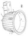
- FIG. 2is a perspective view of a lighting assembly.
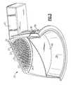
- FIG. 3is a cutaway perspective view of the lighting assembly depicted in FIG. 2 .
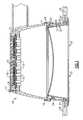
- FIG. 4is a sectional view of the lighting assembly depicted in FIG. 2 .
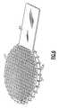
- FIG. 5is a cutaway perspective view of a portion of the lighting assembly depicted in FIG. 2 .
- FIGS. 6 and 7are perspective views of sub-assemblies of the lighting assembly depicted in FIG. 2 .
- FIG. 8is a perspective view of the fixture housing of the lighting assembly depicted in FIG. 2 , with clips attached thereto and with gaps 42 formed therein.
- FIG. 9is a perspective view showing a portion of a clip, a portion of a rim, a portion of a lens and a portion of a fixture housing.
- FIG. 10is a perspective view showing a portion of a clip and a portion of a fixture housing.
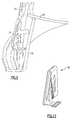
- FIG. 11is a perspective view showing a clip.
- two components in a deviceare “electrically connected,” means that there are no components electrically between the components, the insertion of which materially affect the function or functions provided by the device.
- two componentscan be referred to as being electrically connected, even though they may have a small resistor between them which does not materially affect the function or functions provided by the device (indeed, a wire connecting two components can be thought of as a small resistor); likewise, two components can be referred to as being electrically connected, even though they may have an additional electrical component between them which allows the device to perform an additional function, while not materially affecting the function or functions provided by a device which is identical except for not including the additional component; similarly, two components which are directly connected to each other, or which are directly connected to opposite ends of a wire or a trace on a circuit board or another medium, are electrically connected.
- first structure which is “on” a second structurecan be in contact with the second structure, or can be separated from the second structure by one or more intervening structures (each side, of opposite sides, of which is in contact with the first structure, the second structure or one of the intervening structures).
- first”, “second”, etc.may be used herein to describe various elements, components, regions, layers, sections and/or parameters, these elements, components, regions, layers, sections and/or parameters should not be limited by these terms. These terms are only used to distinguish one element, component, region, layer or section from another region, layer or section. Thus, a first element, component, region, layer or section discussed below could be termed a second element, component, region, layer or section without departing from the teachings of the present invention.
- illuminationmeans that at least some current is being supplied to the solid state light emitter to cause the solid state light emitter to emit at least some light.
- illuminationencompasses situations where the solid state light emitter emits light continuously or intermittently at a rate such that a human eye would perceive it as emitting light continuously, or where a plurality of solid state light emitters of the same color or different colors are emitting light intermittently and/or alternatingly (with or without overlap in “on” times) in such a way that a human eye would perceive them as emitting light continuously (and, in cases where different colors are emitted, as a mixture of those colors).
- the expression “excited”, as used herein when referring to a lumiphor,means that at least some electromagnetic radiation (e.g., visible light, UV light or infrared light) is contacting the lumiphor, causing the lumiphor to emit at least some light.
- the expression “excited”encompasses situations where the lumiphor emits light continuously or intermittently at a rate such that a human eye would perceive it as emitting light continuously, or where a plurality of lumiphors of the same color or different colors are emitting light intermittently and/or alternatingly (with or without overlap in “on” times) in such a way that a human eye would perceive them as emitting light continuously (and, in cases where different colors are emitted, as a mixture of those colors).
- the term “substantially,” e.g., in the expressions “substantially conical”, “substantially parallel”, “substantially frustoconical”, “substantially cylindrical”, “substantially co-linear”, “substantially coaxial”, “substantially semi-elliptical”,means at least about 90% correspondence with the feature recited, e.g.,
- a lighting assemblycomprising:
- At least a first solid state light emitterAt least a first solid state light emitter.
- the housingcan be formed of any material which can be molded and/or shaped, a wide variety of which are well-known and readily available.
- the housingis formed of a material which is an effective heat sink (i.e., which has high thermal conductivity and/or high heat capacity) and/or which is reflective (or which is coated with a reflective material).
- an effective heat sinki.e., which has high thermal conductivity and/or high heat capacity
- reflectiveor which is coated with a reflective material.
- a representative example of a material out of which the fixture housing can be madeis sheet metal.
- the fixture housingcan be any desired shape.
- a representative shape for the fixture housingis hollow cylindrical, e.g., as in conventional “can” light fixtures.
- Other representative shapesinclude hollow conical (or substantially conical), hollow frustoconical (or substantially frustoconical) and hollow semi-elliptical (or substantially semi-elliptical), or any shape which includes one or more portions which are individually selected from among hollow conical (or substantially conical), hollow frustoconical (or substantially frustoconical), hollow cylindrical (or substantially cylindrical) and hollow semi-elliptical (or substantially semi-elliptical).
- the fixture housingcan include a reflective element (and/or one or more of its surfaces are reflective), so that light from some or all of the solid state light emitters is reflected by such reflective surfaces.
- a reflective elementand/or one or more of its surfaces are reflective
- Such reflective elements (and surfaces)are well-known and readily available to persons skilled in the art.
- a representative example of a suitable material out of which a reflective element can be madeis a material marketed by Furukawa (a Japanese corporation) under the trademark MCPET®.
- the fixture housingis cylindrical and includes serrations, whereby a hole can be formed in a construction element (e.g., a wall, a floor or a ceiling) in which the fixture housing is being mounted by holding the fixture housing in contact with the construction element and rotating the fixture housing about its cylindrical axis so as to cut a hole in the construction element, the hole having about the same diameter as the fixture housing.
- a construction elemente.g., a wall, a floor or a ceiling
- the light engine housingis connected to the fixture housing, and it can be made of any suitable material, a wide variety of which are well-known and readily available.
- suitable materiala wide variety of which are well-known and readily available.
- Representative examples of materials out of which the light engine housing can be madeare die cast aluminum, liquid crystal polymer, polyphenylene sulfide (PPS) or a composite material.
- the light engine housingcan be any desired shape.
- a representative shape for the light engine housingis cylindrical.
- the circuit boardcan be made of any suitable material, a wide variety of which are well-known and readily available. Skilled artisans are very familiar with a wide variety of ways to construct circuit boards, and they have access to the materials needed to make such circuit boards. In addition, skilled artisans can readily design the conductive features needed to provide all of the electrical connections needed to operate any of the light engines described herein.
- Representative well-known types of circuit boardsinclude layers of insulating material and conductive material, in which the insulating material is, for example, FR-4 (fiberglass impregnated with epoxy resin) or FR-2 (paper impregnated with phenolic resin) and/or polyimide, and in which the conductive material is etched copper sheets.
- the heat transfer materialcan be made of any suitable material, a wide variety of which are well-known and readily available.
- a representative example of a suitable heat transfer materialis a composition containing 50 to 85 percent by weight epoxy and 15 to 50 percent by weight SiC (silicon carbide)(e.g., #400 SiC).
- the heat transfer materialis in contact with the light engine housing, and can be in any desired shape.
- the light engine housing and the circuit boardtogether define a heat transfer space in which the heat transfer material is positioned (in some cases, the heat transfer material substantially or completely fills the heat transfer space, except for the space(s) occupied by leg(s) extending from the solid state light emitter(s) described below).
- the one or more solid state light emittercan be any suitable solid state light emitter, a wide variety of which are well-known and readily available to persons skilled in the art.
- Solid state light emittersinclude inorganic and organic light emitters. Examples of types of such light emitters include a wide variety of light emitting diodes (inorganic or organic, including polymer light emitting diodes (PLEDs)), laser diodes, thin film electroluminescent devices, light emitting polymers (LEPs), a variety of each of which are well-known in the art (and therefore it is not necessary to describe in detail such devices, and/or the materials out of which such devices are made).
- PLEDspolymer light emitting diodes
- LEPslight emitting polymers
- solid state light emittercan refer to a component including one or more solid state light emitter or a component including one or more solid state light emitter as well as one or more lumiphor.
- a lighting assemblyincludes one or more solid state light emitters which include at least one solid state light emitter and at least one lumiphor which emits light, at least a portion of such light emitted by the luminescent element being emitted in response to luminescent material in the luminescent element being excited by light emitted by the at least one solid state light emitter.
- LEDsAs noted above, one type of solid state light emitter which can be employed are LEDs. Such LEDs can be selected from among any light emitting diodes (a wide variety of which are readily obtainable and well known to those skilled in the art, and therefore it is not necessary to describe in detail such devices, and/or the materials out of which such devices are made). For instance, examples of types of light emitting diodes include inorganic and organic light emitting diodes, a variety of each of which are well-known in the art.
- LEDsmany of which are known in the art, can include lead frames, lumiphors, encapsulant regions, etc.
- Some embodiments according to the present inventioninclude at least a first LED and at least a first lumiphor.
- the light emitted from the first LEDhas a peak wavelength in a range of from 430 nm to 480 nm, and the light emitted from the first lumiphor has a dominant wavelength in a range of from about 555 nm to about 585 nm.
- Some embodiments according to the present inventioninclude at least a first LED, at least a first lumiphor and at least a second LED.
- the light emitted from the first LEDhas a peak wavelength in a range of from 430 nm to 480 nm
- the light emitted from the first lumiphorhas a dominant wavelength in a range of from about 555 nm to about 585 nm
- the light emitted from the second LEDhas a dominant wavelength in a range of from 600 nm to 630 nm.
- Some embodiments according to the present inventioninclude at least a first solid state light emitter (which, in some such embodiments includes at least a first LED and at least a first lumiphor) which, if illuminated, emits light which has x, y color coordinates which define a point which is within an area on a 1931 CIE Chromaticity Diagram enclosed by first, second, third, fourth and fifth line segments, the first line segment connecting a first point to a second point, the second line segment connecting the second point to a third point, the third line segment connecting the third point to a fourth point, the fourth line segment connecting the fourth point to a fifth point, and the fifth line segment connecting the fifth point to the first point, the first point having x, y coordinates of 0.32, 0.40, the second point having x, y coordinates of 0.36, 0.48, the third point having x, y coordinates of 0.43, 0.45, the fourth point having x, y coordinates of 0.42, 0.42, and the fifth point having x, y coordinates
- light of any number of colorscan be mixed by the lighting assemblies according to the present invention.
- Representative examples of blends of light colorsare described in:
- the lighting assemblies according to the present inventioncan comprise any desired number of solid state emitters.
- a lighting assembly according to the present inventioncan include 50 or more light emitting diodes, or can include 100 or more light emitting diodes, etc.
- greater efficiencycan be achieved by using a greater number of smaller light emitting diodes (e.g., 100 light emitting diodes each having a surface area of 0.1 mm 2 vs. 25 light emitting diodes each having a surface area of 0.4 mm 2 but otherwise being identical).
- light emitting diodes which operate at lower current densitiesare generally more efficient.
- Light emitting diodes which draw any particular currentcan be used according to the present invention.
- light emitting diodes which each draw not more than 50 milliampsare employed.
- some embodiments of the lighting assemblies according to the present inventioncan include lumiphors (i.e., luminescence region or luminescent element which comprises at least one luminescent material).
- lumiphori.e., luminescence region or luminescent element which comprises at least one luminescent material.
- the expression “lumiphor”, as used herein,refers to any luminescent element, i.e., any element which includes a luminescent material.
- luminescent materialsalso known as lumiphors or luminophoric media, e.g., as disclosed in U.S. Pat. No. 6,600,175, the entirety of which is hereby incorporated by reference
- a phosphoris a luminescent material that emits a responsive radiation (e.g., visible light) when excited by a source of exciting radiation.
- the responsive radiationhas a wavelength which is different from the wavelength of the exciting radiation.
- Other examples of luminescent materialsinclude scintillators, day glow tapes and inks which glow in the visible spectrum upon illumination with ultraviolet light.
- Luminescent materialscan be categorized as being down-converting, i.e., a material which converts photons to a lower energy level (longer wavelength) or up-converting, i.e., a material which converts photons to a higher energy level (shorter wavelength).
- luminescent materials in LED deviceshas been accomplished by adding the luminescent materials to a clear or translucent encapsulant material (e.g., epoxy-based, silicone-based, glass-based or metal oxide-based material) as discussed above, for example by a blending or coating process.
- a clear or translucent encapsulant materiale.g., epoxy-based, silicone-based, glass-based or metal oxide-based material
- U.S. Pat. No. 6,963,166discloses that a conventional light emitting diode lamp includes a light emitting diode chip, a bullet-shaped transparent housing to cover the light emitting diode chip, leads to supply current to the light emitting diode chip, and a cup reflector for reflecting the emission of the light emitting diode chip in a uniform direction, in which the light emitting diode chip is encapsulated with a first resin portion, which is further encapsulated with a second resin portion.
- the first resin portionis obtained by filling the cup reflector with a resin material and curing it after the light emitting diode chip has been mounted onto the bottom of the cup reflector and then has had its cathode and anode electrodes electrically connected to the leads by way of wires.
- a phosphoris dispersed in the first resin portion so as to be excited with the light A that has been emitted from the light emitting diode chip, the excited phosphor produces fluorescence (“light B”) that has a longer wavelength than the light A, a portion of the light A is transmitted through the first resin portion including the phosphor, and as a result, light C, as a mixture of the light A and light B, is used as illumination.
- light Bfluorescence
- Each solid state light emittertypically is attached to one or two electrically conductive legs.
- at least one solid state light emitterhas at least one electrically conductive leg which extends through the circuit board and at least partially (e.g., 50%, 75%, 90% or more of the distance from the circuit board to a surface of the light engine housing which is opposite the circuit board relative to the heat transfer material) into the heat transfer material.
- the one or more electrically conductive legsare electrically connected to the circuit board by any suitable method, e.g., by soldering.
- the electrically conductive leg(s)can be formed in any suitable shape from any suitable material, a wide variety of which are well-known and available to persons skilled in the art.
- a representative material out of which the legs can be madeis silver-plated copper (or silver-plated mild steel).
- an axis of symmetry of the fixture housingis substantially co-linear with an axis of symmetry of the light engine housing.
- an axis of symmetry of the first legis substantially parallel to the axis of symmetry of the light engine housing, and/or an axis of symmetry of the first solid state light emitter is substantially parallel to the axis of symmetry of the light engine housing.
- the first solid state light emitteris an LED.
- heat sink finsare provided, which extend from the light engine housing away from the heat transfer material.
- Such heat sink finscan be made of any suitable material, a wide variety of which will be readily apparent to persons skilled in the art.
- the lighting assemblyfurther includes at least two clips attached to the fixture housing and extending away from a periphery of the fixture housing.
- Such clipsare designed such that the lighting assembly can, for example, be inserted through an opening in a construction element whereby the clips engage the construction element (or some other construction element) so that the lighting assembly is held in place.
- the lighting assemblyfurther comprises a rim which has an external surface which faces an internal surface of the fixture housing.
- the lighting assemblyfurther comprises clips as described above and at least a first drawstring which, when pulled, causes the clips to retract toward the periphery of the fixture housing in order to enable the lighting assembly to be released and removed from the construction element(s).
- the lighting assemblyfurther comprises a rim as described above which obstructs the first drawstring from view through an opening defined by an internal surface of the rim.
- the lighting assemblyfurther comprises at least a first control device (e.g., a switch) attached to the fixture housing and a rim as described above, in which the rim obstructs the first control device from view through an opening defined by an internal surface of the rim.
- a first control devicee.g., a switch
- the lighting assemblyfurther comprises a rim as described above and one or more mounting screws which connect the fixture housing to a construction element, wherein an internal surface of the rim defines an opening through which light from the one or more solid state light emitter can pass, the rim obstructing the mounting screws from view through the opening.
- a lighting assemblycomprising:
- the first solid state light emitterbeing in contact with a first end of the first electrically conductive leg
- a method of installing a lighting assemblycomprising:
- an electrical conductor on a lighting assemblyto an electrical supply component (e.g., an electrical wire), the lighting assembly comprising a fixture housing and at least two clips attached to the fixture housing and extending away from a periphery of the fixture housing; and
- a construction elemente.g., a wall, a floor or a ceiling
- the methodfurther comprises positioning a lens in the fixture housing and turning the lens, whereby the lens becomes engaged with the fixture housing and is held in place.
- the lensis turned by rotating the lens about an axis substantially coaxial with an axis of the fixture housing.
- a standard diffusing elemente.g., a glass or plastic diffusing element about 0.2 mm thick.
- the methodfurther comprises positioning a rim such that an external surface of the rim faces an internal surface of the fixture housing.
- the lighting assemblycomprises:
- the first solid state light emitteris in contact with a first end of the first electrically conductive leg
- the electrically conductive legis electrically connected to the electrical conductor
- the first electrically conductive legextends through the circuit board
- a second end of the first electrically conductive legextends into the heat transfer material
- the heat transfer materialis in contact with the light engine housing
- the light engine housingis connected to the fixture housing.
- the first emitteris a solid state light emitter, e.g., an LED.
- a method of changing a light emitter in a lighting assemblycomprising:
- the lighting assemblycomprising a fixture housing and at least two clips attached to the fixture housing and extending away from a periphery of the fixture housing.
- the methodfurther comprises inserting the lighting assembly through the hole in the construction element such that the clips engage the construction element, or some other construction element, so as to hold the lighting assembly in place.
- a lighting assemblycan be a device which illuminates an area or volume, e.g., a structure, a swimming pool or spa, a room, a warehouse, an indicator, a road, a parking lot, a vehicle, signage, e.g., road signs, a billboard, a ship, a toy, a mirror, a vessel, an electronic device, a boat, an aircraft, a stadium, a computer, a remote audio device, a remote video device, a cell phone, a tree, a window, an LCD display, a cave, a tunnel, a yard, a lamppost, or a device or array of devices that illuminate an enclosure, or a device that is used for edge or back-lighting (e.g., back light poster, signage, LCD displays), bulb replacements (e.g., for replacing AC incandescent lights, low voltage lights, fluorescent lights, etc.),
- edge or back-lightinge.g., back light poster, signage, LCD displays
- bulb replacements
- the present inventionfurther relates to an illuminated enclosure (the volume of which can be illuminated uniformly or non-uniformly), comprising an enclosed space and at least one lighting assembly according to the present invention, wherein the lighting assembly illuminates at least a portion of the enclosure (uniformly or non-uniformly).
- the present inventionis further directed to an illuminated area, comprising at least one item, e.g., selected from among the group consisting of a structure, a swimming pool or spa, a room, a warehouse, an indicator, a road, a parking lot, a vehicle, signage, e.g., road signs, a billboard, a ship, a toy, a mirror, a vessel, an electronic device, a boat, an aircraft, a stadium, a computer, a remote audio device, a remote video device, a cell phone, a tree, a window, an LCD display, a cave, a tunnel, a yard, a lamppost, etc., having mounted therein or thereon at least one lighting assembly as described herein.
- at least one iteme.g., selected from among the group consisting of a structure, a swimming pool or spa, a room, a warehouse, an indicator, a road, a parking lot, a vehicle, signage, e.g., road signs, a
- the lighting assemblies of the present inventioncan be supplied with electricity in any desired manner. Skilled artisans are familiar with a wide variety of power supplying apparatuses, and any such apparatuses can be employed in connection with the present invention.
- the lighting assemblies of the present inventioncan be electrically connected (or selectively electrically connected) to any desired power source, persons of skill in the art being familiar with a variety of such power sources.
- Embodiments in accordance with the present inventionare described herein with reference to cross-sectional (and/or plan view) illustrations that are schematic illustrations of idealized embodiments of the present invention. As such, variations from the shapes of the illustrations as a result, for example, of manufacturing techniques and/or tolerances, are to be expected. Thus, embodiments of the present invention should not be construed as limited to the particular shapes of regions illustrated herein but are to include deviations in shapes that result, for example, from manufacturing. For example, a molded region illustrated or described as a rectangle will, typically, have rounded or curved features. Thus, the regions illustrated in the figures are schematic in nature and their shapes are not intended to illustrate the precise shape of a region of a device and are not intended to limit the scope of the present invention.
- FIG. 1depicts a first embodiment of a lighting assembly in accordance with the present invention.
- a lighting assembly 10which includes a fixture housing 11 , a light engine housing 12 , a circuit board 13 , a heat transfer material 14 , a plurality of solid state light emitters 15 (in this embodiment, they are LEDs), each being in contact with a pair of electrically conductive legs 16 .
- the electrically conductive legs 16extend through (and are soldered to) the circuit board 13 and into the heat transfer material 14 .
- the heat transfer material 14is in contact with the light engine housing 12 .
- the light engine housing 12is connected to the fixture housing 11 by screws 17 .
- the heat transfer material 14is positioned within a space defined between the light engine housing 12 and the circuit board 13 .
- an axis of symmetry of the fixture housing 11is substantially co-linear with an axis of symmetry of the light engine housing 12 .
- axes of symmetry of the legs 16are substantially parallel to the axis of symmetry of the light engine housing 12 .
- axes of symmetry of the solid state light emittersare substantially parallel to the axis of symmetry of the light engine housing 12 .
- the lighting assembly 10also includes heat sink fins 18 which extend from the light engine housing 12 away from the heat transfer material 14 .
- the lighting assembly 10also includes clips 19 which are attached to the fixture housing 11 and which extend away from a periphery of the fixture housing 11 .
- the lighting assembly 10also includes a rim 20 .
- the rim 20has a rim external surface 21 and a rim internal surface 22 .
- the fixture housing 11has a fixture housing internal surface 23 .
- the rim external surface 21faces the fixture housing internal surface 23 .
- the lighting assembly 10further includes a drawstring 24 which, when pulled, causes the clips 19 to retract toward the periphery of the fixture housing 11 .
- the rim 20obstructs the drawstring 24 from view through an opening 25 defined by the rim internal surface 22 .
- the lighting assembly 10further includes a control device 26 (in the form of a switch) attached to the fixture housing 11 .
- the rim 20obstructs the control device 26 from view through the opening 25 .
- the lighting assembly 10further includes mounting screws 27 which connect the fixture housing 11 to a construction element 28 .
- the rim 20obstructs the mounting screws 27 from view through the opening 25 .
- the legs 16extend into the heat transfer material 14 more than 90% of the distance from the circuit board 13 to the surface of the light engine housing 12 which is opposite the circuit board 13 relative to the heat transfer material 14 .
- FIGS. 2-11depict a second embodiment of a lighting assembly according to the present invention.
- FIG. 2is a perspective view of a lighting assembly 29
- FIG. 4is a sectional view of the lighting assembly 29 .
- the lighting assembly 29includes a fixture housing 30 , a light engine housing 31 , a circuit board 32 , a heat transfer material 33 , a plurality of solid state light emitters 34 (in this embodiment, they are LEDs), each being in contact with a pair of electrically conductive legs 35 .
- the electrically conductive legs 35extend through the circuit board 32 and into the heat transfer material 33 .
- the heat transfer material 33is in contact with the light engine housing 31 .
- the light engine housing 31is connected to the fixture housing 30 by screws 36 (only one screw 36 is shown in FIG. 4 ).
- the lighting assembly 29also includes heat sink fins 37 which extend from the light engine housing 31 away from the heat transfer material 33 .
- the lighting assembly 29also includes clips 38 (one of which is shown in FIG. 2 ) which are attached to the fixture housing 30 and which extend away from a periphery of the fixture housing 30 .
- the lighting assembly 29also includes a rim 39 .
- the lighting assembly 29also includes a lens 40 , which can be inserted by positioning the lens 40 such that tabs which extend outward from the lens 40 engage corresponding gaps 42 in the fixture housing 30 , and twisting the lens (clockwise or counter-clockwise) such that the tabs move within the gaps 42 .
- the lens 40can be removed by twisting in the opposite direction.
- the lighting assembly 29further includes a ballast 41 which converts AC current (e.g., 110 volts) into lower voltage DC current suitable for supplying to the solid state light emitters 34 .
- AC currente.g. 110 volts
- FIG. 3is a cutaway perspective view of the lighting assembly 29 .
- FIG. 5is a cutaway perspective view of a portion of the lighting assembly 29 (without including the heat transfer material 33 , and with each solid state light emitter 34 having only a single leg 35 )
- FIGS. 6 and 7are perspective views of sub-assemblies including the light engine housing 31 (with the heat sink fins 37 formed integrally thereon), the circuit board 32 (not visible in FIG. 6 or in FIG. 7 ), the heat transfer material 33 (also not visible in FIG. 6 or in FIG. 7 ), the solid state light emitters 34 (some visible in FIG. 7 and some partially visible in FIG. 6 ) and a ballast cover 43 (formed integrally with the light engine housing 31 ).
- the sub-assembly of FIG. 7further includes the ballast 41 .
- FIG. 8is a perspective view of the fixture housing 30 , with clips 38 attached thereto and with gaps 42 formed therein.
- FIG. 9is a perspective view showing a portion of a clip 38 , a portion of a rim 39 , a portion of a lens 40 and a portion of a fixture housing 30 .
- FIG. 10is a perspective view showing a portion of a clip 38 and a portion of a fixture housing 30 .
- FIG. 11is a perspective view showing a clip 38 .
- any two or more structural parts of the lighting assemblies described hereincan be integrated. Any structural part of the lighting assemblies described herein can be provided in two or more parts (which are held together, if necessary). Similarly, any two or more functions can be conducted simultaneously, and/or any function can be conducted in a series of steps.
Landscapes
- Engineering & Computer Science (AREA)
- General Engineering & Computer Science (AREA)
- Power Engineering (AREA)
- Non-Portable Lighting Devices Or Systems Thereof (AREA)
- Arrangement Of Elements, Cooling, Sealing, Or The Like Of Lighting Devices (AREA)
- Fastening Of Light Sources Or Lamp Holders (AREA)
Abstract
Description
- removing the light engine housing from the fixture housing;
- removing the light engine from the light engine housing;
- attaching a replacement light engine to the light engine housing; and
- attaching the light engine housing to the fixture housing.
- removing the light engine housing from the fixture housing;
- removing the first light emitter from the light engine;
- attaching a replacement light emitter on the light engine; and
- attaching the light engine housing to the fixture housing.
- the fixture housing;
- a light engine housing;
- a circuit board;
- a heat transfer material;
- at least a first electrically conductive leg; and
- at least a first emitter,
- “substantially parallel” means that two lines (or two planes) diverge from each other at most by an angle of 10% of 90 degrees, i.e., 9 degrees;
- “substantially semi-elliptical” means that a semi-ellipse can be drawn having the formula x2/a2+y1/b2=1, where y≧0, and imaginary axes can be drawn at a location where the y coordinate of each point on the structure is within 0.90 to 1.10 times the value obtained by inserting the x coordinate of such point into such formula;
- the expression “substantially coaxial” means that the axes of the respective surfaces come to within a distance of not more than 10% of the largest dimension of the respective surfaces, and that the respective axes define an angle of not greater than 10 degrees;
- the expression “substantially cylindrical”, as used herein, means that at least 90% of the points in the surface which is characterized as being substantially cylindrical are located on one of or between a pair of imaginary cylindrical structures which are spaced from each other by a distance of not more than 10% of their largest dimension;
- the expression “substantially conical”, as used herein, means that at least 90% of the points in the surface which is characterized as being substantially conical are located on one of or between a pair of imaginary conical structures which are spaced from each other by a distance of not more than 10% of their largest dimension;
- the expression “substantially frustoconical”, as used herein, means that at least 90% of the points in the surface which is characterized as being substantially frustoconical are located on one of or between a pair of imaginary frustoconical structures which are spaced from each other by a distance of not more than 10% of their largest dimension; and
- the expression “co-linear”, as used herein, means that two lines which are described as being co-linear are spaced from each other by not more than 10% of a largest dimension of any structure being described, and that coordinate axes can be defined such that respective x-y slopes of the two lines differ by not more than 10%, and respective x-z slopes of the two lines differ by not more than 10%.
- the fixture housing;
- a light engine housing;
- a circuit board;
- a heat transfer material;
- at least a first electrically conductive leg; and
- at least a first emitter,
Claims (41)
Priority Applications (1)
| Application Number | Priority Date | Filing Date | Title |
|---|---|---|---|
| US11/859,048US8827507B2 (en) | 2006-09-21 | 2007-09-21 | Lighting assemblies, methods of installing same, and methods of replacing lights |
Applications Claiming Priority (2)
| Application Number | Priority Date | Filing Date | Title |
|---|---|---|---|
| US84622206P | 2006-09-21 | 2006-09-21 | |
| US11/859,048US8827507B2 (en) | 2006-09-21 | 2007-09-21 | Lighting assemblies, methods of installing same, and methods of replacing lights |
Publications (2)
| Publication Number | Publication Date |
|---|---|
| US20080084701A1 US20080084701A1 (en) | 2008-04-10 |
| US8827507B2true US8827507B2 (en) | 2014-09-09 |
Family
ID=39046839
Family Applications (1)
| Application Number | Title | Priority Date | Filing Date |
|---|---|---|---|
| US11/859,048Active2027-12-01US8827507B2 (en) | 2006-09-21 | 2007-09-21 | Lighting assemblies, methods of installing same, and methods of replacing lights |
Country Status (4)
| Country | Link |
|---|---|
| US (1) | US8827507B2 (en) |
| EP (1) | EP2076712B1 (en) |
| TW (1) | TW200837308A (en) |
| WO (1) | WO2008036873A2 (en) |
Cited By (9)
| Publication number | Priority date | Publication date | Assignee | Title |
|---|---|---|---|---|
| US20130188388A1 (en)* | 2012-01-20 | 2013-07-25 | Lumencor, Inc. | Solid state continuous white light source |
| USD729432S1 (en)* | 2013-12-09 | 2015-05-12 | Cooper Technologies Company | Luminaire |
| US9417478B2 (en) | 2006-04-18 | 2016-08-16 | Cree, Inc. | Lighting device and lighting method |
| US9423110B1 (en) | 2013-08-29 | 2016-08-23 | Cooper Technologies Company | Full-cutoff LED luminaire with front-pivot power door and heat sink with refractor mounting |
| US9541257B2 (en) | 2012-02-29 | 2017-01-10 | Cree, Inc. | Lens for primarily-elongate light distribution |
| US20170321852A1 (en)* | 2016-04-25 | 2017-11-09 | Innovative Lighting, LLC | Modular luminaire and method of manufacture |
| USD906578S1 (en) | 2018-07-11 | 2020-12-29 | Signify Holding B.V. | Luminaire |
| US11199313B2 (en)* | 2017-03-02 | 2021-12-14 | Simon S.A. | Fastening system for flush mounting a device and flush-mountable device |
| US11791442B2 (en) | 2007-10-31 | 2023-10-17 | Creeled, Inc. | Light emitting diode package and method for fabricating same |
Families Citing this family (173)
| Publication number | Priority date | Publication date | Assignee | Title |
|---|---|---|---|---|
| US7521667B2 (en)* | 2003-06-23 | 2009-04-21 | Advanced Optical Technologies, Llc | Intelligent solid state lighting |
| US7145125B2 (en) | 2003-06-23 | 2006-12-05 | Advanced Optical Technologies, Llc | Integrating chamber cone light using LED sources |
| US7355284B2 (en)* | 2004-03-29 | 2008-04-08 | Cree, Inc. | Semiconductor light emitting devices including flexible film having therein an optical element |
| US20060097385A1 (en)* | 2004-10-25 | 2006-05-11 | Negley Gerald H | Solid metal block semiconductor light emitting device mounting substrates and packages including cavities and heat sinks, and methods of packaging same |
| US8125137B2 (en) | 2005-01-10 | 2012-02-28 | Cree, Inc. | Multi-chip light emitting device lamps for providing high-CRI warm white light and light fixtures including the same |
| US7564180B2 (en) | 2005-01-10 | 2009-07-21 | Cree, Inc. | Light emission device and method utilizing multiple emitters and multiple phosphors |
| US7758223B2 (en)* | 2005-04-08 | 2010-07-20 | Toshiba Lighting & Technology Corporation | Lamp having outer shell to radiate heat of light source |
| US7872430B2 (en) | 2005-11-18 | 2011-01-18 | Cree, Inc. | Solid state lighting panels with variable voltage boost current sources |
| JP5249773B2 (en)* | 2005-11-18 | 2013-07-31 | クリー インコーポレイテッド | Solid state lighting panel with variable voltage boost current source |
| US8514210B2 (en) | 2005-11-18 | 2013-08-20 | Cree, Inc. | Systems and methods for calibrating solid state lighting panels using combined light output measurements |
| JP5166278B2 (en)* | 2005-11-18 | 2013-03-21 | クリー インコーポレイテッド | Solid-state lighting tile |
| WO2007075742A2 (en) | 2005-12-21 | 2007-07-05 | Cree Led Lighting Solutions, Inc. | Lighting device |
| EP1963740A4 (en)* | 2005-12-21 | 2009-04-29 | Cree Led Lighting Solutions | Lighting device and lighting method |
| CN101351891B (en) | 2005-12-22 | 2014-11-19 | 科锐公司 | lighting device |
| US8441179B2 (en) | 2006-01-20 | 2013-05-14 | Cree, Inc. | Lighting devices having remote lumiphors that are excited by lumiphor-converted semiconductor excitation sources |
| US9084328B2 (en) | 2006-12-01 | 2015-07-14 | Cree, Inc. | Lighting device and lighting method |
| US9335006B2 (en) | 2006-04-18 | 2016-05-10 | Cree, Inc. | Saturated yellow phosphor converted LED and blue converted red LED |
| US7828460B2 (en)* | 2006-04-18 | 2010-11-09 | Cree, Inc. | Lighting device and lighting method |
| US8998444B2 (en)* | 2006-04-18 | 2015-04-07 | Cree, Inc. | Solid state lighting devices including light mixtures |
| US7821194B2 (en) | 2006-04-18 | 2010-10-26 | Cree, Inc. | Solid state lighting devices including light mixtures |
| WO2007124036A2 (en) | 2006-04-20 | 2007-11-01 | Cree Led Lighting Solutions, Inc. | Lighting device and lighting method |
| WO2007142946A2 (en) | 2006-05-31 | 2007-12-13 | Cree Led Lighting Solutions, Inc. | Lighting device and method of lighting |
| US7665862B2 (en) | 2006-09-12 | 2010-02-23 | Cree, Inc. | LED lighting fixture |
| US7766508B2 (en)* | 2006-09-12 | 2010-08-03 | Cree, Inc. | LED lighting fixture |
| CN101595342B (en) | 2006-10-23 | 2012-10-24 | 科锐公司 | Lighting device and installation method of light engine housing and/or decoration in lighting device |
| US8029155B2 (en)* | 2006-11-07 | 2011-10-04 | Cree, Inc. | Lighting device and lighting method |
| US9605828B2 (en) | 2006-11-14 | 2017-03-28 | Cree, Inc. | Light engine assemblies |
| KR101513738B1 (en) | 2006-11-14 | 2015-04-21 | 크리, 인코포레이티드 | Lighting assemblies and components for lighting assemblies |
| US7888875B2 (en)* | 2006-11-21 | 2011-02-15 | Ceit Entreprises | Lighting device such as a LED reading light |
| EP2100076B1 (en) | 2006-11-30 | 2014-08-13 | Cree, Inc. | Light fixtures, lighting devices, and components for the same |
| CN101617411B (en) | 2006-11-30 | 2012-07-11 | 科锐公司 | Lighting device and lighting method |
| US9441793B2 (en) | 2006-12-01 | 2016-09-13 | Cree, Inc. | High efficiency lighting device including one or more solid state light emitters, and method of lighting |
| US9310026B2 (en) | 2006-12-04 | 2016-04-12 | Cree, Inc. | Lighting assembly and lighting method |
| US7918581B2 (en) | 2006-12-07 | 2011-04-05 | Cree, Inc. | Lighting device and lighting method |
| US8258682B2 (en)* | 2007-02-12 | 2012-09-04 | Cree, Inc. | High thermal conductivity packaging for solid state light emitting apparatus and associated assembling methods |
| US20080198572A1 (en) | 2007-02-21 | 2008-08-21 | Medendorp Nicholas W | LED lighting systems including luminescent layers on remote reflectors |
| TWI560405B (en) | 2007-02-22 | 2016-12-01 | Cree Inc | Lighting devices, methods of lighting, light filters and methods of filtering light |
| US7824070B2 (en) | 2007-03-22 | 2010-11-02 | Cree, Inc. | LED lighting fixture |
| US8049709B2 (en) | 2007-05-08 | 2011-11-01 | Cree, Inc. | Systems and methods for controlling a solid state lighting panel |
| KR20100022969A (en) | 2007-05-08 | 2010-03-03 | 크리 엘이디 라이팅 솔루션즈, 인크. | Lighting device and lighting method |
| EP2156090B1 (en) | 2007-05-08 | 2016-07-06 | Cree, Inc. | Lighting device and lighting method |
| US7744243B2 (en) | 2007-05-08 | 2010-06-29 | Cree Led Lighting Solutions, Inc. | Lighting device and lighting method |
| JP2010527510A (en) | 2007-05-08 | 2010-08-12 | クリー エル イー ディー ライティング ソリューションズ インコーポレイテッド | Lighting device and lighting method |
| US10030824B2 (en) | 2007-05-08 | 2018-07-24 | Cree, Inc. | Lighting device and lighting method |
| EP2165113B1 (en) | 2007-05-08 | 2016-06-22 | Cree, Inc. | Lighting devices and methods for lighting |
| US7863635B2 (en)* | 2007-08-07 | 2011-01-04 | Cree, Inc. | Semiconductor light emitting devices with applied wavelength conversion materials |
| US20090039375A1 (en)* | 2007-08-07 | 2009-02-12 | Cree, Inc. | Semiconductor light emitting devices with separated wavelength conversion materials and methods of forming the same |
| EP2191655B8 (en)* | 2007-09-13 | 2019-01-09 | Philips Lighting Holding B.V. | Illumination device for pixelated illumination |
| CN101836042B (en)* | 2007-09-21 | 2014-11-05 | 库帕技术公司 | Light emitting diode recessed light fixture |
| JP2011501417A (en)* | 2007-10-10 | 2011-01-06 | クリー エル イー ディー ライティング ソリューションズ インコーポレイテッド | Lighting device and manufacturing method |
| CA2640913C (en)* | 2007-10-12 | 2017-05-09 | The L.D. Kichler Co. | Positionable lighting systems and methods |
| JP4569683B2 (en) | 2007-10-16 | 2010-10-27 | 東芝ライテック株式会社 | Light emitting element lamp and lighting apparatus |
| US10256385B2 (en) | 2007-10-31 | 2019-04-09 | Cree, Inc. | Light emitting die (LED) packages and related methods |
| JP5353216B2 (en) | 2008-01-07 | 2013-11-27 | 東芝ライテック株式会社 | LED bulb and lighting fixture |
| US8350461B2 (en)* | 2008-03-28 | 2013-01-08 | Cree, Inc. | Apparatus and methods for combining light emitters |
| US7972036B1 (en) | 2008-04-30 | 2011-07-05 | Genlyte Thomas Group Llc | Modular bollard luminaire louver |
| US7985004B1 (en) | 2008-04-30 | 2011-07-26 | Genlyte Thomas Group Llc | Luminaire |
| US8388193B2 (en) | 2008-05-23 | 2013-03-05 | Ruud Lighting, Inc. | Lens with TIR for off-axial light distribution |
| EP2993387A1 (en)* | 2008-05-23 | 2016-03-09 | Cree, Inc. | Recessed led lighting fixture |
| EP2301071B1 (en)* | 2008-05-29 | 2019-05-08 | Cree, Inc. | Light source with near field mixing |
| JP5391767B2 (en) | 2008-05-30 | 2014-01-15 | 東芝ライテック株式会社 | Light emitting device and lighting apparatus |
| US8240875B2 (en) | 2008-06-25 | 2012-08-14 | Cree, Inc. | Solid state linear array modules for general illumination |
| CN103470983A (en) | 2008-06-27 | 2013-12-25 | 东芝照明技术株式会社 | Light-emitting element lamp and lighting equipment |
| GB0814255D0 (en)* | 2008-08-05 | 2008-09-10 | Radiant Res Ltd | A collimated illumination system using an extended apparent source size to provide a high quality and efficient fixture |
| US7934851B1 (en) | 2008-08-19 | 2011-05-03 | Koninklijke Philips Electronics N.V. | Vertical luminaire |
| JP5077693B2 (en)* | 2008-08-28 | 2012-11-21 | 東芝ライテック株式会社 | lighting equipment |
| US7611264B1 (en)* | 2008-08-28 | 2009-11-03 | Li-Hong Technological Co., Ltd. | LED lamp |
| CN101709857B (en)* | 2008-09-16 | 2012-01-25 | 东芝照明技术株式会社 | Light source unit and lighting apparatus using same |
| US9425172B2 (en) | 2008-10-24 | 2016-08-23 | Cree, Inc. | Light emitter array |
| US8858032B2 (en)* | 2008-10-24 | 2014-10-14 | Cree, Inc. | Lighting device, heat transfer structure and heat transfer element |
| US8008845B2 (en)* | 2008-10-24 | 2011-08-30 | Cree, Inc. | Lighting device which includes one or more solid state light emitting device |
| JP2010129227A (en)* | 2008-11-25 | 2010-06-10 | Toshiba Lighting & Technology Corp | Recessed illuminating device |
| US20100226139A1 (en) | 2008-12-05 | 2010-09-09 | Permlight Products, Inc. | Led-based light engine |
| US10197240B2 (en)* | 2009-01-09 | 2019-02-05 | Cree, Inc. | Lighting device |
| US8070328B1 (en) | 2009-01-13 | 2011-12-06 | Koninkliljke Philips Electronics N.V. | LED downlight |
| US8220970B1 (en)* | 2009-02-11 | 2012-07-17 | Koninklijke Philips Electronics N.V. | Heat dissipation assembly for an LED downlight |
| US8333631B2 (en) | 2009-02-19 | 2012-12-18 | Cree, Inc. | Methods for combining light emitting devices in a package and packages including combined light emitting devices |
| US7967652B2 (en) | 2009-02-19 | 2011-06-28 | Cree, Inc. | Methods for combining light emitting devices in a package and packages including combined light emitting devices |
| JP5333758B2 (en) | 2009-02-27 | 2013-11-06 | 東芝ライテック株式会社 | Lighting device and lighting fixture |
| US8950910B2 (en)* | 2009-03-26 | 2015-02-10 | Cree, Inc. | Lighting device and method of cooling lighting device |
| US8123378B1 (en) | 2009-05-15 | 2012-02-28 | Koninklijke Philips Electronics N.V. | Heatsink for cooling at least one LED |
| US8197091B1 (en) | 2009-05-15 | 2012-06-12 | Koninklijke Philips Electronics N.V. | LED unit for installation in a post-top luminaire |
| US9841162B2 (en) | 2009-05-18 | 2017-12-12 | Cree, Inc. | Lighting device with multiple-region reflector |
| US8921876B2 (en)* | 2009-06-02 | 2014-12-30 | Cree, Inc. | Lighting devices with discrete lumiphor-bearing regions within or on a surface of remote elements |
| JP5354191B2 (en)* | 2009-06-30 | 2013-11-27 | 東芝ライテック株式会社 | Light bulb shaped lamp and lighting equipment |
| JP5348410B2 (en)* | 2009-06-30 | 2013-11-20 | 東芝ライテック株式会社 | Lamp with lamp and lighting equipment |
| US8596837B1 (en) | 2009-07-21 | 2013-12-03 | Cooper Technologies Company | Systems, methods, and devices providing a quick-release mechanism for a modular LED light engine |
| CA2768777C (en) | 2009-07-21 | 2017-11-28 | Cooper Technologies Company | Interfacing a light emitting diode (led) module to a heat sink assembly, a light reflector and electrical circuits |
| JP2011049527A (en) | 2009-07-29 | 2011-03-10 | Toshiba Lighting & Technology Corp | Led lighting equipment |
| US8716952B2 (en) | 2009-08-04 | 2014-05-06 | Cree, Inc. | Lighting device having first, second and third groups of solid state light emitters, and lighting arrangement |
| US8648546B2 (en)* | 2009-08-14 | 2014-02-11 | Cree, Inc. | High efficiency lighting device including one or more saturated light emitters, and method of lighting |
| US9605844B2 (en) | 2009-09-01 | 2017-03-28 | Cree, Inc. | Lighting device with heat dissipation elements |
| US8901829B2 (en)* | 2009-09-24 | 2014-12-02 | Cree Led Lighting Solutions, Inc. | Solid state lighting apparatus with configurable shunts |
| JP2011071242A (en) | 2009-09-24 | 2011-04-07 | Toshiba Lighting & Technology Corp | Light emitting device and illuminating device |
| US10264637B2 (en) | 2009-09-24 | 2019-04-16 | Cree, Inc. | Solid state lighting apparatus with compensation bypass circuits and methods of operation thereof |
| US8901845B2 (en) | 2009-09-24 | 2014-12-02 | Cree, Inc. | Temperature responsive control for lighting apparatus including light emitting devices providing different chromaticities and related methods |
| US9713211B2 (en)* | 2009-09-24 | 2017-07-18 | Cree, Inc. | Solid state lighting apparatus with controllable bypass circuits and methods of operation thereof |
| US9285103B2 (en) | 2009-09-25 | 2016-03-15 | Cree, Inc. | Light engines for lighting devices |
| US8777449B2 (en) | 2009-09-25 | 2014-07-15 | Cree, Inc. | Lighting devices comprising solid state light emitters |
| US9068719B2 (en) | 2009-09-25 | 2015-06-30 | Cree, Inc. | Light engines for lighting devices |
| US9353933B2 (en) | 2009-09-25 | 2016-05-31 | Cree, Inc. | Lighting device with position-retaining element |
| US9464801B2 (en) | 2009-09-25 | 2016-10-11 | Cree, Inc. | Lighting device with one or more removable heat sink elements |
| JP2011091033A (en)* | 2009-09-25 | 2011-05-06 | Toshiba Lighting & Technology Corp | Light-emitting module, bulb-shaped lamp and lighting equipment |
| US8602579B2 (en) | 2009-09-25 | 2013-12-10 | Cree, Inc. | Lighting devices including thermally conductive housings and related structures |
| US8678618B2 (en) | 2009-09-25 | 2014-03-25 | Toshiba Lighting & Technology Corporation | Self-ballasted lamp having a light-transmissive member in contact with light emitting elements and lighting equipment incorporating the same |
| EP2302298A1 (en) | 2009-09-25 | 2011-03-30 | Toshiba Lighting & Technology Corporation | Lighting apparatus |
| US8324789B2 (en)* | 2009-09-25 | 2012-12-04 | Toshiba Lighting & Technology Corporation | Self-ballasted lamp and lighting equipment |
| CN102032481B (en)* | 2009-09-25 | 2014-01-08 | 东芝照明技术株式会社 | Lighting lamps and lighting fixtures with sockets |
| CN102630288B (en) | 2009-09-25 | 2015-09-09 | 科锐公司 | Lighting fixtures with low glare and high brightness level uniformity |
| CN102630290A (en)* | 2009-09-25 | 2012-08-08 | 科锐公司 | Lighting device having heat dissipation element |
| WO2011037876A1 (en) | 2009-09-25 | 2011-03-31 | Cree, Inc. | Lighting device having heat dissipation element |
| US9030120B2 (en) | 2009-10-20 | 2015-05-12 | Cree, Inc. | Heat sinks and lamp incorporating same |
| US9217542B2 (en) | 2009-10-20 | 2015-12-22 | Cree, Inc. | Heat sinks and lamp incorporating same |
| US9435493B2 (en) | 2009-10-27 | 2016-09-06 | Cree, Inc. | Hybrid reflector system for lighting device |
| USD673322S1 (en) | 2009-11-19 | 2012-12-25 | Cree, Inc. | Light engine for a lighting device |
| US8506127B2 (en) | 2009-12-11 | 2013-08-13 | Koninklijke Philips N.V. | Lens frame with a LED support surface and heat dissipating structure |
| US8536615B1 (en) | 2009-12-16 | 2013-09-17 | Cree, Inc. | Semiconductor device structures with modulated and delta doping and related methods |
| US8604461B2 (en)* | 2009-12-16 | 2013-12-10 | Cree, Inc. | Semiconductor device structures with modulated doping and related methods |
| US8511851B2 (en) | 2009-12-21 | 2013-08-20 | Cree, Inc. | High CRI adjustable color temperature lighting devices |
| DE102009060897B4 (en)* | 2009-12-30 | 2014-02-06 | Erco Gmbh | Downlight |
| WO2011088388A2 (en) | 2010-01-14 | 2011-07-21 | Cooper Technologies Company | Led downlight with improved light output |
| US8508116B2 (en) | 2010-01-27 | 2013-08-13 | Cree, Inc. | Lighting device with multi-chip light emitters, solid state light emitter support members and lighting elements |
| US9175811B2 (en) | 2010-02-12 | 2015-11-03 | Cree, Inc. | Solid state lighting device, and method of assembling the same |
| US8773007B2 (en) | 2010-02-12 | 2014-07-08 | Cree, Inc. | Lighting devices that comprise one or more solid state light emitters |
| US9518715B2 (en)* | 2010-02-12 | 2016-12-13 | Cree, Inc. | Lighting devices that comprise one or more solid state light emitters |
| US20110267821A1 (en) | 2010-02-12 | 2011-11-03 | Cree, Inc. | Lighting device with heat dissipation elements |
| KR20120128139A (en) | 2010-02-12 | 2012-11-26 | 크리, 인코포레이티드 | Lighting devices that comprise one or more solid state light emitters |
| DE202010002676U1 (en) | 2010-02-23 | 2011-07-26 | Zumtobel Lighting Gmbh | Recessed luminaire with base body and domed reflector |
| JP5257622B2 (en)* | 2010-02-26 | 2013-08-07 | 東芝ライテック株式会社 | Light bulb shaped lamp and lighting equipment |
| US8632196B2 (en) | 2010-03-03 | 2014-01-21 | Cree, Inc. | LED lamp incorporating remote phosphor and diffuser with heat dissipation features |
| US9275979B2 (en) | 2010-03-03 | 2016-03-01 | Cree, Inc. | Enhanced color rendering index emitter through phosphor separation |
| US10359151B2 (en) | 2010-03-03 | 2019-07-23 | Ideal Industries Lighting Llc | Solid state lamp with thermal spreading elements and light directing optics |
| US8376593B2 (en)* | 2010-04-30 | 2013-02-19 | Osram Sylvania Inc. | Thermal trim for a luminaire |
| US8476836B2 (en) | 2010-05-07 | 2013-07-02 | Cree, Inc. | AC driven solid state lighting apparatus with LED string including switched segments |
| US8684559B2 (en) | 2010-06-04 | 2014-04-01 | Cree, Inc. | Solid state light source emitting warm light with high CRI |
| KR101285889B1 (en)* | 2010-06-23 | 2013-07-11 | 엘지전자 주식회사 | LED lighting fixtures |
| US8896005B2 (en)* | 2010-07-29 | 2014-11-25 | Cree, Inc. | Lighting devices that comprise one or more solid state light emitters |
| US10451251B2 (en) | 2010-08-02 | 2019-10-22 | Ideal Industries Lighting, LLC | Solid state lamp with light directing optics and diffuser |
| CN103097805B (en)* | 2010-09-10 | 2016-05-04 | 皇家飞利浦电子股份有限公司 | For the device of spotlighting |
| CN102537719B (en)* | 2010-11-18 | 2015-03-04 | 东芝照明技术株式会社 | Luminaire |
| US8556469B2 (en) | 2010-12-06 | 2013-10-15 | Cree, Inc. | High efficiency total internal reflection optic for solid state lighting luminaires |
| US9786811B2 (en) | 2011-02-04 | 2017-10-10 | Cree, Inc. | Tilted emission LED array |
| US11251164B2 (en) | 2011-02-16 | 2022-02-15 | Creeled, Inc. | Multi-layer conversion material for down conversion in solid state lighting |
| ES2401227B1 (en)* | 2011-03-02 | 2014-02-18 | Víctor Oller Pardos | LIGHTING DEVICE. |
| USD657087S1 (en) | 2011-05-13 | 2012-04-03 | Lsi Industries, Inc. | Lighting |
| US8585238B2 (en) | 2011-05-13 | 2013-11-19 | Lsi Industries, Inc. | Dual zone lighting apparatus |
| US9839083B2 (en) | 2011-06-03 | 2017-12-05 | Cree, Inc. | Solid state lighting apparatus and circuits including LED segments configured for targeted spectral power distribution and methods of operating the same |
| US20130003346A1 (en)* | 2011-06-28 | 2013-01-03 | Cree, Inc. | Compact high efficiency remote led module |
| US10842016B2 (en) | 2011-07-06 | 2020-11-17 | Cree, Inc. | Compact optically efficient solid state light source with integrated thermal management |
| US8742671B2 (en) | 2011-07-28 | 2014-06-03 | Cree, Inc. | Solid state lighting apparatus and methods using integrated driver circuitry |
| US9151457B2 (en)* | 2012-02-03 | 2015-10-06 | Cree, Inc. | Lighting device and method of installing light emitter |
| US9151477B2 (en) | 2012-02-03 | 2015-10-06 | Cree, Inc. | Lighting device and method of installing light emitter |
| US9541258B2 (en) | 2012-02-29 | 2017-01-10 | Cree, Inc. | Lens for wide lateral-angle distribution |
| US10408429B2 (en) | 2012-02-29 | 2019-09-10 | Ideal Industries Lighting Llc | Lens for preferential-side distribution |
| US9739455B2 (en) | 2012-04-17 | 2017-08-22 | Abl Ip Holding Llc | LED light engines |
| US8882311B2 (en)* | 2012-04-27 | 2014-11-11 | Cree, Inc. | Lens assembly for lighting fixture |
| US8870410B2 (en) | 2012-07-30 | 2014-10-28 | Ultravision Holdings, Llc | Optical panel for LED light source |
| US8974077B2 (en) | 2012-07-30 | 2015-03-10 | Ultravision Technologies, Llc | Heat sink for LED light source |
| US9062873B2 (en) | 2012-07-30 | 2015-06-23 | Ultravision Technologies, Llc | Structure for protecting LED light source from moisture |
| GB2526226B (en)* | 2013-03-06 | 2016-06-29 | Aurora Ltd | Improved downlights |
| WO2014168765A1 (en)* | 2013-04-13 | 2014-10-16 | Neonode Inc. | Optimized hemi-ellipsoidal led shell |
| CN104241262B (en) | 2013-06-14 | 2020-11-06 | 惠州科锐半导体照明有限公司 | Light emitting device and display device |
| DE102013112305A1 (en)* | 2013-11-08 | 2015-05-13 | Kaiser Gmbh & Co. Kg | Installation housing for electric lights |
| US20150247620A1 (en)* | 2014-02-28 | 2015-09-03 | Evans Edward Thompson, III | Outdoor Lighting System |
| CN103994371B (en)* | 2014-05-22 | 2017-02-15 | 长沙宁格光电科技有限公司 | Tunnel lighting lamp adopting LED light source |
| CN103982832A (en)* | 2014-05-30 | 2014-08-13 | 昆山生态屋建筑技术有限公司 | LED tunnel lamp |
| DE102015114955A1 (en)* | 2015-09-07 | 2017-03-09 | Cruse Spezialmaschinen GmbH | Lighting system and imaging device |
| CN105782831B (en)* | 2016-04-02 | 2018-08-24 | 嘉兴维特拉电气科技有限公司 | Led tunnel lamp fixing device |
| FI127768B (en) | 2017-04-10 | 2019-02-15 | Teknoware Oy | Lighting card and method for producing a lighting card |
| WO2019138797A1 (en)* | 2018-01-11 | 2019-07-18 | 日本精機株式会社 | Display device |
| NL2025081B1 (en)* | 2020-03-09 | 2021-10-19 | Schreder Sa | Luminaire head with improved heatsink |
| CN111457319A (en)* | 2020-04-14 | 2020-07-28 | 昆山航理机载设备股份有限公司 | Airborne general type indicating lamp |
| US11655974B2 (en)* | 2021-06-11 | 2023-05-23 | Eaton Intelligent Power Limited | Composite fin heat sink |
Citations (79)
| Publication number | Priority date | Publication date | Assignee | Title |
|---|---|---|---|---|
| US3052749A (en) | 1957-11-26 | 1962-09-04 | Martin Marietta Corp | Lightweight printed circuit panel |
| US3263023A (en) | 1964-04-09 | 1966-07-26 | Westinghouse Electric Corp | Printed circuits on honeycomb support with pierceable insulation therebetween |
| US4689442A (en) | 1985-02-18 | 1987-08-25 | O. Key Printed Wiring Co., Ltd. | Printed circuit board and method of manufacturing same |
| US5116689A (en) | 1988-11-07 | 1992-05-26 | Rohr Industries, Inc. | Apparatus and method for selectively increasing density and thermal conductivity of honeycomb structures |
| US5400229A (en)* | 1994-06-08 | 1995-03-21 | Formosa Industrial Computing, Inc. | Receptacle apparatus for light emitting diodes |
| US5567041A (en)* | 1995-08-14 | 1996-10-22 | Slocum; Karl | Self supporting recessed ceiling fixture |
| DE19528459A1 (en) | 1995-08-03 | 1997-02-13 | Garufo Gmbh | LED display apparatus with carrier plate - has heat carrier plates connected to transfer heat from carrier plate to heat dissipation surface |
| JPH0955457A (en) | 1995-08-15 | 1997-02-25 | Mitsubishi Alum Co Ltd | Heat sink and its manufacture |
| US5632551A (en) | 1994-07-18 | 1997-05-27 | Grote Industries, Inc. | LED vehicle lamp assembly |
| US5808592A (en)* | 1994-04-28 | 1998-09-15 | Toyoda Gosei Co., Ltd. | Integrated light-emitting diode lamp and method of producing the same |
| US5826970A (en)* | 1996-12-17 | 1998-10-27 | Effetre U.S.A. | Light transmissive trim plate for recessed lighting fixture |
| US5850126A (en) | 1997-04-11 | 1998-12-15 | Kanbar; Maurice S. | Screw-in led lamp |
| US5876831A (en) | 1997-05-13 | 1999-03-02 | Lockheed Martin Corporation | High thermal conductivity plugs for structural panels |
| US5941625A (en)* | 1997-12-11 | 1999-08-24 | Bazz Inc. | Spring clip for a recessed light fixture assembly |
| JPH11264668A (en) | 1998-03-18 | 1999-09-28 | Tabai Espec Corp | Heat equalizer for hot plate |
| US6045240A (en)* | 1996-06-27 | 2000-04-04 | Relume Corporation | LED lamp assembly with means to conduct heat away from the LEDS |
| US6161910A (en)* | 1999-12-14 | 2000-12-19 | Aerospace Lighting Corporation | LED reading light |
| US6278607B1 (en) | 1998-08-06 | 2001-08-21 | Dell Usa, L.P. | Smart bi-metallic heat spreader |
| US6340868B1 (en) | 1997-08-26 | 2002-01-22 | Color Kinetics Incorporated | Illumination components |
| EP1174307A2 (en) | 2000-07-21 | 2002-01-23 | Aerospace Lighting Corporation | Lighting bracket assembly |
| US6375338B1 (en)* | 1996-09-17 | 2002-04-23 | Power & Light, Llc | Modular lighting fixture |
| US6435691B1 (en)* | 1999-11-29 | 2002-08-20 | Watkins Manufacturing Corporation | Lighting apparatus for portable spas and the like |
| US6441943B1 (en) | 1997-04-02 | 2002-08-27 | Gentex Corporation | Indicators and illuminators using a semiconductor radiation emitter package |
| US6482520B1 (en) | 2000-02-25 | 2002-11-19 | Jing Wen Tzeng | Thermal management system |
| US20030067778A1 (en) | 2001-10-09 | 2003-04-10 | Jean-Francois Vernusset | Fixing support for a recessed mounting luminaire |
| US6578994B1 (en)* | 1999-06-11 | 2003-06-17 | Diehl Luftfahrt Elecktronik Gmbh | Spotlight, in particular a reading light in cabins of vehicles and craft |
| US6578986B2 (en) | 2001-06-29 | 2003-06-17 | Permlight Products, Inc. | Modular mounting arrangement and method for light emitting diodes |
| US6595656B2 (en)* | 2000-10-13 | 2003-07-22 | Koito Manufacturing Co., Ltd. | Cabin lamp |
| US20030189831A1 (en) | 2002-04-09 | 2003-10-09 | Kenji Yoneda | Light irradiating unit , lighting unit and method for manufacturing lighting unit |
| US20030210554A1 (en)* | 2002-05-10 | 2003-11-13 | Rolf Broelemann | Lamp for a vehicle, in particular reading lamp for an aircraft |
| US6659632B2 (en) | 2001-11-09 | 2003-12-09 | Solidlite Corporation | Light emitting diode lamp |
| US6712486B1 (en) | 1999-10-19 | 2004-03-30 | Permlight Products, Inc. | Mounting arrangement for light emitting diodes |
| US6740972B2 (en) | 1998-06-24 | 2004-05-25 | Honeywell International Inc. | Electronic device having fibrous interface |
| US20040105247A1 (en) | 2002-12-03 | 2004-06-03 | Calvin Nate Howard | Diffusing backlight assembly |
| US6788541B1 (en) | 2003-05-07 | 2004-09-07 | Bear Hsiung | LED matrix moldule |
| US6789921B1 (en) | 2003-03-25 | 2004-09-14 | Rockwell Collins | Method and apparatus for backlighting a dual mode liquid crystal display |
| US6791257B1 (en) | 1999-02-05 | 2004-09-14 | Japan Energy Corporation | Photoelectric conversion functional element and production method thereof |
| US6800932B2 (en) | 1999-05-27 | 2004-10-05 | Advanced Analogic Technologies, Inc. | Package for semiconductor die containing symmetrical lead and heat sink |
| US6805474B2 (en) | 2001-08-31 | 2004-10-19 | Gentex Corporation | Vehicle lamp assembly with heat sink |
| US20040208009A1 (en)* | 2001-06-12 | 2004-10-21 | Mardon Paul Francis | Lighting unit with improved cooling |
| US6864573B2 (en) | 2003-05-06 | 2005-03-08 | Daimlerchrysler Corporation | Two piece heat sink and device package |
| US20050051789A1 (en) | 2003-09-09 | 2005-03-10 | Negley Gerald H. | Solid metal block mounting substrates for semiconductor light emitting devices, and oxidizing methods for fabricating same |
| US6871983B2 (en)* | 2001-10-25 | 2005-03-29 | Tir Systems Ltd. | Solid state continuous sealed clean room light fixture |
| US20050077525A1 (en) | 2003-10-09 | 2005-04-14 | Manuel Lynch | LED luminaire |
| US6880954B2 (en) | 2002-11-08 | 2005-04-19 | Smd Software, Inc. | High intensity photocuring system |
| US20050094105A1 (en) | 2003-10-07 | 2005-05-05 | Seiko Epson Corporation | Optical device and rear projector |
| US20050111234A1 (en) | 2003-11-26 | 2005-05-26 | Lumileds Lighting U.S., Llc | LED lamp heat sink |
| US20050128751A1 (en) | 2003-05-05 | 2005-06-16 | Color Kinetics, Incorporated | Lighting methods and systems |
| US20050168986A1 (en) | 2004-01-30 | 2005-08-04 | Scott Wegner | Reflector assemblies for luminaires |
| US20050174780A1 (en) | 2004-02-06 | 2005-08-11 | Daejin Dmp Co., Ltd. | LED light |
| US6949772B2 (en) | 2001-08-09 | 2005-09-27 | Matsushita Electric Industrial Co., Ltd. | LED illumination apparatus and card-type LED illumination source |
| US20050225966A1 (en) | 2004-07-14 | 2005-10-13 | Hartmann Richard Jr | Light fixture |
| US20050237739A1 (en) | 2004-04-27 | 2005-10-27 | Lee Kian S | Illumination panel with reverse mounted solid-state light generating source array |
| EP1600691A1 (en) | 2004-05-05 | 2005-11-30 | Lumodan ApS | Lamps and lamp assemblies |
| US7014336B1 (en) | 1999-11-18 | 2006-03-21 | Color Kinetics Incorporated | Systems and methods for generating and modulating illumination conditions |
| US20060061539A1 (en) | 2004-09-23 | 2006-03-23 | Samsung Electronics Co., Ltd. | Light generating device, backlight assembly having the same, and display apparatus having the backlight assembly |
| US7030486B1 (en) | 2003-05-29 | 2006-04-18 | Marshall Paul N | High density integrated circuit package architecture |
| US20060098440A1 (en) | 2004-11-05 | 2006-05-11 | David Allen | Solid state lighting device with improved thermal management, improved power management, adjustable intensity, and interchangable lenses |
| EP1674792A2 (en) | 2004-12-23 | 2006-06-28 | Belisario Pini | Swivel support, eg. for lights |
| US20060146531A1 (en)* | 2004-12-30 | 2006-07-06 | Ann Reo | Linear lighting apparatus with improved heat dissipation |
| US7095110B2 (en) | 2004-05-21 | 2006-08-22 | Gelcore, Llc | Light emitting diode apparatuses with heat pipes for thermal management |
| US20060187660A1 (en) | 2005-02-18 | 2006-08-24 | Au Optronics Corporation | Backlight module having device for fastening lighting units |
| US20060221620A1 (en)* | 2005-03-31 | 2006-10-05 | Philip Thomas | Replacement module for recessed light |
| US7121688B2 (en) | 2004-03-01 | 2006-10-17 | Rempel Lee W | Box light |
| US7144140B2 (en) | 2005-02-25 | 2006-12-05 | Tsung-Ting Sun | Heat dissipating apparatus for lighting utility |
| US20070074755A1 (en) | 2005-10-03 | 2007-04-05 | Nanosolar, Inc. | Photovoltaic module with rigidizing backplane |
| US7210832B2 (en) | 2003-09-26 | 2007-05-01 | Advanced Thermal Devices, Inc. | Illumination apparatus of light emitting diodes and method of heat dissipation thereof |
| US7213940B1 (en) | 2005-12-21 | 2007-05-08 | Led Lighting Fixtures, Inc. | Lighting device and lighting method |
| US7226189B2 (en) | 2005-04-15 | 2007-06-05 | Taiwan Oasis Technology Co., Ltd. | Light emitting diode illumination apparatus |
| US7234844B2 (en) | 2002-12-11 | 2007-06-26 | Charles Bolta | Light emitting diode (L.E.D.) lighting fixtures with emergency back-up and scotopic enhancement |
| US7258475B2 (en) | 2004-02-26 | 2007-08-21 | Cateye Co., Ltd. | Headlamp |
| US7284874B2 (en) | 2004-06-28 | 2007-10-23 | Lg.Philips Lcd Co., Ltd. | LED backlight unit including cooling structure |
| US20070247414A1 (en) | 2006-04-21 | 2007-10-25 | Cree, Inc. | Solid state luminaires for general illumination |
| US20070268707A1 (en)* | 2006-05-22 | 2007-11-22 | Edison Price Lighting, Inc. | LED array wafer lighting fixture |
| WO2008079161A1 (en) | 2006-12-20 | 2008-07-03 | Rensselaer Polytechnic Institute | Lighting system using multiple colored light-emitting sources and deffuser element |
| US20090097249A1 (en)* | 2007-10-16 | 2009-04-16 | Foxsemicon Integrated Technology, Inc. | Light emitting diode based light source assembly |
| US7566154B2 (en)* | 2006-09-25 | 2009-07-28 | B/E Aerospace, Inc. | Aircraft LED dome light having rotatably releasable housing mounted within mounting flange |
| US8079736B2 (en)* | 2007-09-05 | 2011-12-20 | Toshiba Lighting & Technology Corporation | Lighting apparatus |
| US8136965B2 (en)* | 2007-05-07 | 2012-03-20 | Cree, Inc. | Light fixtures and lighting devices |
Family Cites Families (4)
| Publication number | Priority date | Publication date | Assignee | Title |
|---|---|---|---|---|
| US4739460A (en)* | 1984-08-06 | 1988-04-19 | Cooper Industries, Inc. | Spring clips for a recessed light fixture |
| DE29809630U1 (en)* | 1998-05-28 | 1998-09-17 | Ridi Leuchten Gmbh, 72417 Jungingen | Recessed luminaire |
| US6684573B2 (en)* | 2001-05-04 | 2004-02-03 | Thyssen Elevator Capital Corp. | Elevator door sill assembly |
| US6470972B1 (en)* | 2001-08-03 | 2002-10-29 | Leslie O. Trampe | Gardening tool |
- 2007
- 2007-09-21TWTW096135308Apatent/TW200837308A/enunknown
- 2007-09-21WOPCT/US2007/079123patent/WO2008036873A2/enactiveApplication Filing
- 2007-09-21USUS11/859,048patent/US8827507B2/enactiveActive
- 2007-09-21EPEP07842945.3Apatent/EP2076712B1/enactiveActive
Patent Citations (83)
| Publication number | Priority date | Publication date | Assignee | Title |
|---|---|---|---|---|
| US3052749A (en) | 1957-11-26 | 1962-09-04 | Martin Marietta Corp | Lightweight printed circuit panel |
| US3263023A (en) | 1964-04-09 | 1966-07-26 | Westinghouse Electric Corp | Printed circuits on honeycomb support with pierceable insulation therebetween |
| US4689442A (en) | 1985-02-18 | 1987-08-25 | O. Key Printed Wiring Co., Ltd. | Printed circuit board and method of manufacturing same |
| US5116689A (en) | 1988-11-07 | 1992-05-26 | Rohr Industries, Inc. | Apparatus and method for selectively increasing density and thermal conductivity of honeycomb structures |
| US5808592A (en)* | 1994-04-28 | 1998-09-15 | Toyoda Gosei Co., Ltd. | Integrated light-emitting diode lamp and method of producing the same |
| US5400229A (en)* | 1994-06-08 | 1995-03-21 | Formosa Industrial Computing, Inc. | Receptacle apparatus for light emitting diodes |
| US5632551A (en) | 1994-07-18 | 1997-05-27 | Grote Industries, Inc. | LED vehicle lamp assembly |
| DE19528459A1 (en) | 1995-08-03 | 1997-02-13 | Garufo Gmbh | LED display apparatus with carrier plate - has heat carrier plates connected to transfer heat from carrier plate to heat dissipation surface |
| US5567041A (en)* | 1995-08-14 | 1996-10-22 | Slocum; Karl | Self supporting recessed ceiling fixture |
| JPH0955457A (en) | 1995-08-15 | 1997-02-25 | Mitsubishi Alum Co Ltd | Heat sink and its manufacture |
| US6045240A (en)* | 1996-06-27 | 2000-04-04 | Relume Corporation | LED lamp assembly with means to conduct heat away from the LEDS |
| US6375338B1 (en)* | 1996-09-17 | 2002-04-23 | Power & Light, Llc | Modular lighting fixture |
| US5826970A (en)* | 1996-12-17 | 1998-10-27 | Effetre U.S.A. | Light transmissive trim plate for recessed lighting fixture |
| US6441943B1 (en) | 1997-04-02 | 2002-08-27 | Gentex Corporation | Indicators and illuminators using a semiconductor radiation emitter package |
| US5850126A (en) | 1997-04-11 | 1998-12-15 | Kanbar; Maurice S. | Screw-in led lamp |
| US5876831A (en) | 1997-05-13 | 1999-03-02 | Lockheed Martin Corporation | High thermal conductivity plugs for structural panels |
| US6340868B1 (en) | 1997-08-26 | 2002-01-22 | Color Kinetics Incorporated | Illumination components |
| US5941625A (en)* | 1997-12-11 | 1999-08-24 | Bazz Inc. | Spring clip for a recessed light fixture assembly |
| JPH11264668A (en) | 1998-03-18 | 1999-09-28 | Tabai Espec Corp | Heat equalizer for hot plate |
| US6740972B2 (en) | 1998-06-24 | 2004-05-25 | Honeywell International Inc. | Electronic device having fibrous interface |
| US6278607B1 (en) | 1998-08-06 | 2001-08-21 | Dell Usa, L.P. | Smart bi-metallic heat spreader |
| US6791257B1 (en) | 1999-02-05 | 2004-09-14 | Japan Energy Corporation | Photoelectric conversion functional element and production method thereof |
| US6800932B2 (en) | 1999-05-27 | 2004-10-05 | Advanced Analogic Technologies, Inc. | Package for semiconductor die containing symmetrical lead and heat sink |
| US6578994B1 (en)* | 1999-06-11 | 2003-06-17 | Diehl Luftfahrt Elecktronik Gmbh | Spotlight, in particular a reading light in cabins of vehicles and craft |
| US6712486B1 (en) | 1999-10-19 | 2004-03-30 | Permlight Products, Inc. | Mounting arrangement for light emitting diodes |
| US7014336B1 (en) | 1999-11-18 | 2006-03-21 | Color Kinetics Incorporated | Systems and methods for generating and modulating illumination conditions |
| US6435691B1 (en)* | 1999-11-29 | 2002-08-20 | Watkins Manufacturing Corporation | Lighting apparatus for portable spas and the like |
| US6161910A (en)* | 1999-12-14 | 2000-12-19 | Aerospace Lighting Corporation | LED reading light |
| US6482520B1 (en) | 2000-02-25 | 2002-11-19 | Jing Wen Tzeng | Thermal management system |
| EP1174307A2 (en) | 2000-07-21 | 2002-01-23 | Aerospace Lighting Corporation | Lighting bracket assembly |
| US6350043B1 (en)* | 2000-07-21 | 2002-02-26 | Aerospace Lighting Corporation | Behind panel mount, directional lighting bracket |
| US6595656B2 (en)* | 2000-10-13 | 2003-07-22 | Koito Manufacturing Co., Ltd. | Cabin lamp |
| US20040208009A1 (en)* | 2001-06-12 | 2004-10-21 | Mardon Paul Francis | Lighting unit with improved cooling |
| US20030218878A1 (en) | 2001-06-29 | 2003-11-27 | Permlight Products, Inc. | Modular mounting arrangement and method for light emitting diodes |
| US6578986B2 (en) | 2001-06-29 | 2003-06-17 | Permlight Products, Inc. | Modular mounting arrangement and method for light emitting diodes |
| US6846093B2 (en) | 2001-06-29 | 2005-01-25 | Permlight Products, Inc. | Modular mounting arrangement and method for light emitting diodes |
| US6949772B2 (en) | 2001-08-09 | 2005-09-27 | Matsushita Electric Industrial Co., Ltd. | LED illumination apparatus and card-type LED illumination source |
| US6805474B2 (en) | 2001-08-31 | 2004-10-19 | Gentex Corporation | Vehicle lamp assembly with heat sink |
| US20030067778A1 (en) | 2001-10-09 | 2003-04-10 | Jean-Francois Vernusset | Fixing support for a recessed mounting luminaire |
| EP1310730A1 (en) | 2001-10-09 | 2003-05-14 | Koninklijke Philips Electronics N.V. | Mounting device, in particular for a recessed luminaire |
| US6871983B2 (en)* | 2001-10-25 | 2005-03-29 | Tir Systems Ltd. | Solid state continuous sealed clean room light fixture |
| US6659632B2 (en) | 2001-11-09 | 2003-12-09 | Solidlite Corporation | Light emitting diode lamp |
| US20030189831A1 (en) | 2002-04-09 | 2003-10-09 | Kenji Yoneda | Light irradiating unit , lighting unit and method for manufacturing lighting unit |
| US20030210554A1 (en)* | 2002-05-10 | 2003-11-13 | Rolf Broelemann | Lamp for a vehicle, in particular reading lamp for an aircraft |
| US6880954B2 (en) | 2002-11-08 | 2005-04-19 | Smd Software, Inc. | High intensity photocuring system |
| US20040105247A1 (en) | 2002-12-03 | 2004-06-03 | Calvin Nate Howard | Diffusing backlight assembly |
| US7234844B2 (en) | 2002-12-11 | 2007-06-26 | Charles Bolta | Light emitting diode (L.E.D.) lighting fixtures with emergency back-up and scotopic enhancement |
| US6789921B1 (en) | 2003-03-25 | 2004-09-14 | Rockwell Collins | Method and apparatus for backlighting a dual mode liquid crystal display |
| US20050128751A1 (en) | 2003-05-05 | 2005-06-16 | Color Kinetics, Incorporated | Lighting methods and systems |
| US6864573B2 (en) | 2003-05-06 | 2005-03-08 | Daimlerchrysler Corporation | Two piece heat sink and device package |
| US6788541B1 (en) | 2003-05-07 | 2004-09-07 | Bear Hsiung | LED matrix moldule |
| US7030486B1 (en) | 2003-05-29 | 2006-04-18 | Marshall Paul N | High density integrated circuit package architecture |
| US20050051789A1 (en) | 2003-09-09 | 2005-03-10 | Negley Gerald H. | Solid metal block mounting substrates for semiconductor light emitting devices, and oxidizing methods for fabricating same |
| US7210832B2 (en) | 2003-09-26 | 2007-05-01 | Advanced Thermal Devices, Inc. | Illumination apparatus of light emitting diodes and method of heat dissipation thereof |
| US20050094105A1 (en) | 2003-10-07 | 2005-05-05 | Seiko Epson Corporation | Optical device and rear projector |
| US20050077525A1 (en) | 2003-10-09 | 2005-04-14 | Manuel Lynch | LED luminaire |
| US20050111234A1 (en) | 2003-11-26 | 2005-05-26 | Lumileds Lighting U.S., Llc | LED lamp heat sink |
| US20050168986A1 (en) | 2004-01-30 | 2005-08-04 | Scott Wegner | Reflector assemblies for luminaires |
| US20050174780A1 (en) | 2004-02-06 | 2005-08-11 | Daejin Dmp Co., Ltd. | LED light |
| US7258475B2 (en) | 2004-02-26 | 2007-08-21 | Cateye Co., Ltd. | Headlamp |
| US7121688B2 (en) | 2004-03-01 | 2006-10-17 | Rempel Lee W | Box light |
| US20050237739A1 (en) | 2004-04-27 | 2005-10-27 | Lee Kian S | Illumination panel with reverse mounted solid-state light generating source array |
| EP1600691A1 (en) | 2004-05-05 | 2005-11-30 | Lumodan ApS | Lamps and lamp assemblies |
| US7095110B2 (en) | 2004-05-21 | 2006-08-22 | Gelcore, Llc | Light emitting diode apparatuses with heat pipes for thermal management |
| US7284874B2 (en) | 2004-06-28 | 2007-10-23 | Lg.Philips Lcd Co., Ltd. | LED backlight unit including cooling structure |
| US20050225966A1 (en) | 2004-07-14 | 2005-10-13 | Hartmann Richard Jr | Light fixture |
| US20060061539A1 (en) | 2004-09-23 | 2006-03-23 | Samsung Electronics Co., Ltd. | Light generating device, backlight assembly having the same, and display apparatus having the backlight assembly |
| US20060098440A1 (en) | 2004-11-05 | 2006-05-11 | David Allen | Solid state lighting device with improved thermal management, improved power management, adjustable intensity, and interchangable lenses |
| EP1674792A2 (en) | 2004-12-23 | 2006-06-28 | Belisario Pini | Swivel support, eg. for lights |
| US20060146531A1 (en)* | 2004-12-30 | 2006-07-06 | Ann Reo | Linear lighting apparatus with improved heat dissipation |
| US20060187660A1 (en) | 2005-02-18 | 2006-08-24 | Au Optronics Corporation | Backlight module having device for fastening lighting units |
| US7144140B2 (en) | 2005-02-25 | 2006-12-05 | Tsung-Ting Sun | Heat dissipating apparatus for lighting utility |
| US20060221620A1 (en)* | 2005-03-31 | 2006-10-05 | Philip Thomas | Replacement module for recessed light |
| US7226189B2 (en) | 2005-04-15 | 2007-06-05 | Taiwan Oasis Technology Co., Ltd. | Light emitting diode illumination apparatus |
| US20070074755A1 (en) | 2005-10-03 | 2007-04-05 | Nanosolar, Inc. | Photovoltaic module with rigidizing backplane |
| US7213940B1 (en) | 2005-12-21 | 2007-05-08 | Led Lighting Fixtures, Inc. | Lighting device and lighting method |
| US20070247414A1 (en) | 2006-04-21 | 2007-10-25 | Cree, Inc. | Solid state luminaires for general illumination |
| US20070268707A1 (en)* | 2006-05-22 | 2007-11-22 | Edison Price Lighting, Inc. | LED array wafer lighting fixture |
| US7566154B2 (en)* | 2006-09-25 | 2009-07-28 | B/E Aerospace, Inc. | Aircraft LED dome light having rotatably releasable housing mounted within mounting flange |
| WO2008079161A1 (en) | 2006-12-20 | 2008-07-03 | Rensselaer Polytechnic Institute | Lighting system using multiple colored light-emitting sources and deffuser element |
| US8136965B2 (en)* | 2007-05-07 | 2012-03-20 | Cree, Inc. | Light fixtures and lighting devices |
| US8079736B2 (en)* | 2007-09-05 | 2011-12-20 | Toshiba Lighting & Technology Corporation | Lighting apparatus |
| US20090097249A1 (en)* | 2007-10-16 | 2009-04-16 | Foxsemicon Integrated Technology, Inc. | Light emitting diode based light source assembly |
Non-Patent Citations (33)
| Title |
|---|
| Cree, Inc., "Cree® Xlamp® 7090 XR-E Series LED Binning and Labeling," Application Note: CLD-AP08.000, 7pp (2006). |
| Cree, Inc., "Cree® Xlamp® 7090 XR-E Series LED Data Sheet," Datasheet: CLD-DS05.000, 10 pp (2006). |
| Cree, Inc., "Cree® Xlamp® 7090 XR-E Series LED Secondary Optics," Datasheet: CLD-DS07.000, 3 pp (2004-2006). |
| McMaster-Carr Supply Company, "Multipurpose Aluminum (Alloy 6061), specification sheets," Retrieved Dec. 14, 2006 from www.mcmaster.com/param/asp/Psearch2.asp?regTyp=parametric&act=psearch%F . . . , 3 pp. |
| U.S. Appl. No. 11/379,709, filed Apr. 21, 2006. |
| U.S. Appl. No. 11/379,726, filed Apr. 21, 2006. |
| U.S. Appl. No. 11/408,767, filed Apr. 21, 2006. |
| U.S. Appl. No. 11/613,692, filed Dec. 20, 2006. |
| U.S. Appl. No. 11/613,714, filed Dec. 20, 2006. |
| U.S. Appl. No. 11/613,733, filed Dec. 20, 2006. |
| U.S. Appl. No. 11/614,180, filed Dec. 21, 2006. |
| U.S. Appl. No. 11/624,811, filed Jan. 19, 2007. |
| U.S. Appl. No. 11/626,483, filed Jan. 24, 2007. |
| U.S. Appl. No. 11/673,951, filed Feb. 12, 2007. |
| U.S. Appl. No. 11/736,761, filed Apr. 18, 2007. |
| U.S. Appl. No. 11/736,799, filed Apr. 18, 2007. |
| U.S. Appl. No. 11/737,321, filed Apr. 19, 2007. |
| U.S. Appl. No. 11/743,754, filed May 3, 2007. |
| U.S. Appl. No. 11/751,982, filed May 22, 2007. |
| U.S. Appl. No. 11/751,990, filed May 22, 2007. |
| U.S. Appl. No. 11/753,103, filed May 24, 2007. |
| U.S. Appl. No. 11/755,162, filed May 30, 2007. |
| U.S. Appl. No. 11/843,243, filed Aug. 22, 2007. |
| U.S. Appl. No. 11/854,744, filed Sep. 13, 2007. |
| U.S. Appl. No. 11/870,679, filed Oct. 11, 2007. |
| U.S. Appl. No. 11/877,038, filed Oct. 23, 2007. |
| U.S. Appl. No. 11/936,163, filed Nov. 7, 2007. |
| U.S. Appl. No. 11/939,052, filed Nov. 13, 2007. |
| U.S. Appl. No. 11/939,059, filed Nov. 13, 2007. |
| U.S. Appl. No. 11/948,021, filed Nov. 30, 2007. |
| U.S. Appl. No. 11/948,041, filed Nov. 30, 2007. |
| U.S. Appl. No. 11/951,626, filed Dec. 6, 2007. |
| U.S. Appl. No. 12/035,604, filed Feb. 22, 2008. |
Cited By (11)
| Publication number | Priority date | Publication date | Assignee | Title |
|---|---|---|---|---|
| US9417478B2 (en) | 2006-04-18 | 2016-08-16 | Cree, Inc. | Lighting device and lighting method |
| US11791442B2 (en) | 2007-10-31 | 2023-10-17 | Creeled, Inc. | Light emitting diode package and method for fabricating same |
| US20130188388A1 (en)* | 2012-01-20 | 2013-07-25 | Lumencor, Inc. | Solid state continuous white light source |
| US8967811B2 (en)* | 2012-01-20 | 2015-03-03 | Lumencor, Inc. | Solid state continuous white light source |
| US9541257B2 (en) | 2012-02-29 | 2017-01-10 | Cree, Inc. | Lens for primarily-elongate light distribution |
| US9423110B1 (en) | 2013-08-29 | 2016-08-23 | Cooper Technologies Company | Full-cutoff LED luminaire with front-pivot power door and heat sink with refractor mounting |
| US9845945B1 (en) | 2013-08-29 | 2017-12-19 | Cooper Technologies Company | Full-cutoff LED luminaire with front-pivot power door and heat sink with refractor mounting |
| USD729432S1 (en)* | 2013-12-09 | 2015-05-12 | Cooper Technologies Company | Luminaire |
| US20170321852A1 (en)* | 2016-04-25 | 2017-11-09 | Innovative Lighting, LLC | Modular luminaire and method of manufacture |
| US11199313B2 (en)* | 2017-03-02 | 2021-12-14 | Simon S.A. | Fastening system for flush mounting a device and flush-mountable device |
| USD906578S1 (en) | 2018-07-11 | 2020-12-29 | Signify Holding B.V. | Luminaire |
Also Published As
| Publication number | Publication date |
|---|---|
| WO2008036873A2 (en) | 2008-03-27 |
| US20080084701A1 (en) | 2008-04-10 |
| EP2076712A2 (en) | 2009-07-08 |
| EP2076712B1 (en) | 2020-08-12 |
| TW200837308A (en) | 2008-09-16 |
| WO2008036873A3 (en) | 2008-06-26 |
Similar Documents
| Publication | Publication Date | Title |
|---|---|---|
| US8827507B2 (en) | Lighting assemblies, methods of installing same, and methods of replacing lights | |
| US8439531B2 (en) | Lighting assemblies and components for lighting assemblies | |
| EP2095014B1 (en) | Light engine assemblies | |
| US8057070B2 (en) | Self-ballasted solid state lighting devices | |
| US8008845B2 (en) | Lighting device which includes one or more solid state light emitting device | |
| US9068719B2 (en) | Light engines for lighting devices | |
| US20110267812A1 (en) | Solid state lighting device, and method of assembling the same | |
| US8337045B2 (en) | Lighting device and lighting method | |
| EP2089654A1 (en) | Lighting device and lighting method | |
| EP2066963B1 (en) | Lighting device |
Legal Events
| Date | Code | Title | Description |
|---|---|---|---|
| AS | Assignment | Owner name:LED LIGHTING FIXTURES, INC., NORTH CAROLINA Free format text:ASSIGNMENT OF ASSIGNORS INTEREST;ASSIGNORS:VAN DE VEN, ANTONY PAUL;NEGLEY, GERALD H.;REEL/FRAME:020294/0647;SIGNING DATES FROM 20071001 TO 20071003 Owner name:LED LIGHTING FIXTURES, INC., NORTH CAROLINA Free format text:ASSIGNMENT OF ASSIGNORS INTEREST;ASSIGNORS:VAN DE VEN, ANTONY PAUL;NEGLEY, GERALD H.;SIGNING DATES FROM 20071001 TO 20071003;REEL/FRAME:020294/0647 | |
| AS | Assignment | Owner name:CREE LED LIGHTING SOLUTIONS, INC., NORTH CAROLINA Free format text:MERGER;ASSIGNOR:LED LIGHTING FIXTURES, INC.;REEL/FRAME:020764/0891 Effective date:20080229 | |
| AS | Assignment | Owner name:CREE, INC., NORTH CAROLINA Free format text:MERGER;ASSIGNOR:CREE LED LIGHTING SOLUTIONS, INC.;REEL/FRAME:025126/0955 Effective date:20100621 | |
| STCF | Information on status: patent grant | Free format text:PATENTED CASE | |
| CC | Certificate of correction | ||
| MAFP | Maintenance fee payment | Free format text:PAYMENT OF MAINTENANCE FEE, 4TH YEAR, LARGE ENTITY (ORIGINAL EVENT CODE: M1551) Year of fee payment:4 | |
| AS | Assignment | Owner name:IDEAL INDUSTRIES LIGHTING LLC, ILLINOIS Free format text:ASSIGNMENT OF ASSIGNORS INTEREST;ASSIGNOR:CREE, INC.;REEL/FRAME:049927/0473 Effective date:20190513 | |
| MAFP | Maintenance fee payment | Free format text:PAYMENT OF MAINTENANCE FEE, 8TH YEAR, LARGE ENTITY (ORIGINAL EVENT CODE: M1552); ENTITY STATUS OF PATENT OWNER: LARGE ENTITY Year of fee payment:8 | |
| AS | Assignment | Owner name:FGI WORLDWIDE LLC, NEW YORK Free format text:SECURITY INTEREST;ASSIGNOR:IDEAL INDUSTRIES LIGHTING LLC;REEL/FRAME:064897/0413 Effective date:20230908 |