US8827201B2 - Rotorcraft structural element for reducing aerodynamic drag - Google Patents
Rotorcraft structural element for reducing aerodynamic dragDownload PDFInfo
- Publication number
- US8827201B2 US8827201B2US13/307,448US201113307448AUS8827201B2US 8827201 B2US8827201 B2US 8827201B2US 201113307448 AUS201113307448 AUS 201113307448AUS 8827201 B2US8827201 B2US 8827201B2
- Authority
- US
- United States
- Prior art keywords
- fairing
- rear portion
- trailing edges
- shapes
- discontinuous
- Prior art date
- Legal status (The legal status is an assumption and is not a legal conclusion. Google has not performed a legal analysis and makes no representation as to the accuracy of the status listed.)
- Expired - Fee Related
Links
Images

Classifications
- B—PERFORMING OPERATIONS; TRANSPORTING
- B64—AIRCRAFT; AVIATION; COSMONAUTICS
- B64C—AEROPLANES; HELICOPTERS
- B64C23/00—Influencing air flow over aircraft surfaces, not otherwise provided for
- B64C23/06—Influencing air flow over aircraft surfaces, not otherwise provided for by generating vortices
- B—PERFORMING OPERATIONS; TRANSPORTING
- B64—AIRCRAFT; AVIATION; COSMONAUTICS
- B64C—AEROPLANES; HELICOPTERS
- B64C27/00—Rotorcraft; Rotors peculiar thereto
- B64C27/82—Rotorcraft; Rotors peculiar thereto characterised by the provision of an auxiliary rotor or fluid-jet device for counter-balancing lifting rotor torque or changing direction of rotorcraft
- B—PERFORMING OPERATIONS; TRANSPORTING
- B64—AIRCRAFT; AVIATION; COSMONAUTICS
- B64C—AEROPLANES; HELICOPTERS
- B64C1/00—Fuselages; Constructional features common to fuselages, wings, stabilising surfaces or the like
- B64C1/0009—Aerodynamic aspects
- B—PERFORMING OPERATIONS; TRANSPORTING
- B64—AIRCRAFT; AVIATION; COSMONAUTICS
- B64C—AEROPLANES; HELICOPTERS
- B64C21/00—Influencing air flow over aircraft surfaces by affecting boundary layer flow
- B64C21/10—Influencing air flow over aircraft surfaces by affecting boundary layer flow using other surface properties, e.g. roughness
- B—PERFORMING OPERATIONS; TRANSPORTING
- B64—AIRCRAFT; AVIATION; COSMONAUTICS
- B64C—AEROPLANES; HELICOPTERS
- B64C27/00—Rotorcraft; Rotors peculiar thereto
- B64C27/04—Helicopters
- B—PERFORMING OPERATIONS; TRANSPORTING
- B64—AIRCRAFT; AVIATION; COSMONAUTICS
- B64C—AEROPLANES; HELICOPTERS
- B64C7/00—Structures or fairings not otherwise provided for
- B—PERFORMING OPERATIONS; TRANSPORTING
- B64—AIRCRAFT; AVIATION; COSMONAUTICS
- B64C—AEROPLANES; HELICOPTERS
- B64C27/00—Rotorcraft; Rotors peculiar thereto
- B64C27/82—Rotorcraft; Rotors peculiar thereto characterised by the provision of an auxiliary rotor or fluid-jet device for counter-balancing lifting rotor torque or changing direction of rotorcraft
- B64C2027/8254—Shrouded tail rotors, e.g. "Fenestron" fans
- Y—GENERAL TAGGING OF NEW TECHNOLOGICAL DEVELOPMENTS; GENERAL TAGGING OF CROSS-SECTIONAL TECHNOLOGIES SPANNING OVER SEVERAL SECTIONS OF THE IPC; TECHNICAL SUBJECTS COVERED BY FORMER USPC CROSS-REFERENCE ART COLLECTIONS [XRACs] AND DIGESTS
- Y02—TECHNOLOGIES OR APPLICATIONS FOR MITIGATION OR ADAPTATION AGAINST CLIMATE CHANGE
- Y02T—CLIMATE CHANGE MITIGATION TECHNOLOGIES RELATED TO TRANSPORTATION
- Y02T50/00—Aeronautics or air transport
- Y02T50/10—Drag reduction
- Y02T50/12—
- Y02T50/162—
- Y02T50/166—
Definitions
- the inventionrelates to the general technical field of aviation, and more precisely to the construction of aircraft structural elements, in particular for rotary wing aircraft such as rotorcraft.
- aircraft structural elementsthat need to be distinguished from airfoil surfaces, often give rise to aerodynamic drag.
- rotorcraftspecifically helicopters
- the present inventionrelates more particularly to a ducted tail rotor for a helicopter, known as a Fenestron®, or more generally a structural element that has a certain amount of thickness, and that is of a shape that generates aerodynamic drag.
- certain ducted tail rotors of the Fenestron® typehave a rear portion that is terminated by a clearly-defined base, e.g. by a part that extends substantially orthogonally relative to the forward direction and that closes the rear portion of the Fenestron fairing. Downstream from its clearly-defined base the fairing of such a tail rotor thus presents a width that suddenly becomes zero.
- a clearly-defined basee.g. by a part that extends substantially orthogonally relative to the forward direction and that closes the rear portion of the Fenestron fairing.
- the fairing of such a tail rotorthus presents a width that suddenly becomes zero.
- Such a shapegives rise to a considerable amount of wake and is responsible for a non-negligible portion of the aerodynamic drag. Such a shape therefore penalizes the aerodynamic performance of the aircraft in forward flight.
- the relative thicknessis the value of the ratio between the maximum thickness of the fairing in the direction extending transversely to the flow divided by its length (the dimension that it occupies in the longitudinal direction of the flow).
- Such a relative thicknessrequires a large amount of length (chord of the fairing), given the fairing needs sufficient width to enable it to house the anti-torque rotor.
- the use of such a profiled portiontherefore increases the weight of the aircraft. This increase in weight is also located very far to the rear of the center of gravity of the aircraft, thereby giving rise to problems of centering the aircraft.
- such a profiled portiongives rise to problems in terms of flight quality, in particular heading instability of the aircraft. Such heading instability may indeed appear with a reduced drag in flight, but where the location of the separation of the airflow from the structural element is at a position that is unstable.
- the flapping of the wakeSince the flapping of the wake is not localized in the same place, it gives rise to natural self-sustaining oscillations in the forces generated by the fairing, in particular in terms of yaw.
- the pilotcan then sense yaw oscillations about the heading (route) as set by the pilot that come from the tail of the helicopter.
- Such a profiled portionmay also generate asymmetry in terms of lateral flight of the aircraft.
- a rotorcraft rotor bladeis also known, e.g. from document EP 0 724 691, that has aerodynamic portions in relief that improve the aerodynamic characteristics of the blade, in order to enhance the flow of the surrounding fluid.
- Those portions in reliefare formed in particular by waves arranged in the general plane of the blade, both as projections and as depressions. Those waves give rise to variations in the thickness of the blade that are distributed along its span, both on its suction side and on its pressure side.
- Those portions in reliefare also formed by varying the curvature of the blade in its depth direction, said portions in relief being arranged as sawteeth distributed along the span of said blade, at least at its leading edge, and possibly also at its trailing edge. That document therefore relates very specifically to airfoil surfaces of a rotorcraft.
- Document GB 577 524describes a rotary wing aircraft having an anti-torque tail rotor. Suction openings for the anti-torque rotor are provided on opposite side walls of a tail boom of the aircraft. The blades of a main rotor drive a stream downwards, which stream is forced into the fuselage through an air inlet under the main rotor, and is then channeled to the suction openings in the opposite side walls of the tail beam.
- Document EP 1 527 992describes an airfoil surface in the form of a wing with a flap arranged to create a vortex. Concave grooves are provided in the longitudinal direction of the aircraft.
- Document JP 2000/255496describes horizontal grooves in an anti-torque rotor fairing, the grooves all being parallel in a plane that is longitudinal and horizontal, and the grooves all being transversely continuous from one edge to the other of the fairing.
- the inventionproposes a novel structural element for an aircraft of the rotorcraft kind, in particular a helicopter, the element being of a shape that enables the above-mentioned limitations to be overcome, and consequently that enables the aerodynamic drag of the aircraft in forward flight to be reduced.
- the inventionproposes a portion of fairing for an anti-torque rotor, with the shape of said portion of fairing serving to reduce the aerodynamic drag of the aircraft in forward flight.
- the inventionproposes a Fenestron having a fairing of a shape that serves to reduce the discontinuous perturbed drag of the aircraft in forward flight.
- the inventionis in the form of a fairing for a structural element of a rotorcraft, the fairing including a rear portion that is substantially orthogonal to the longitudinal direction of the aircraft, said rear portion extending between two spaced-apart trailing edges and thus presenting a determined width, said rear portion closing at least part of the internal volume defined by the fairing and generating aerodynamic drag in forward flight, wherein the rear portion presents, at least at the trailing edges, a shape that is perturbed on the streamlines of the air-flow.
- the perturbed shapecomprises projecting and recessed portions in relief extending over the entire surface of the rear portion that is located between the trailing edges.
- the shape of the projecting and recessed portions in reliefconstitutes undulations of regular dimensions.
- the shape of the projecting and recessed portions in reliefconstitutes undulations of irregular dimensions.
- At least some of the undulationsextend from one trailing edge to the other.
- At least some of the undulationsextend from one trailing edge at least to an intermediate zone of the rear portion, said at least one intermediate zone being located between the two trailing edges.
- the perturbed shapeincludes protrusions along each trailing edge.
- the perturbed shapeincludes cavities along each trailing edge.
- the inventionis in the form of a ducted anti-torque tail rotor for a helicopter that includes a hub having blades mounted thereon, means for driving the hub in rotation, and means for adjusting the pitch of the blades, said rotor including a fairing as described above.
- the fairingincludes open lateral portions that are substantially parallel on either side of the hub, each of said lateral portions terminating towards the rear in a trailing edge, said rear portion of the fairing forming a base that extends between the trailing edges.
- the base-forming rear portionpresents curvature at least in a vertical and longitudinal plane of the aircraft.
- the novel structural element or fairingmay either present a shape that incorporates technical characteristics that mitigate the above-mentioned drawbacks, or else it may include additional parts (fitted and/or adhesively bonded thereto), e.g. presented in the form of a kit.
- the inventionis in the form of a rotorcraft, in particular a helicopter, that includes a ducted anti-torque tail rotor as described above.
- the inventionpresents the advantage whereby its shape, in particular the shape of its rear portion, serves to reduce the size of the separation of the mean aerodynamic flow downstream from the structural element or Fenestron. This serves to reduce drag and consequently to reduce the fuel consumption of the aircraft.
- Another advantage of the inventionlies in the fact that it constitutes a solution that is passive, thereby giving rise to no recurring costs for inspection or maintenance.
- Another advantage of the inventionlies in the fact that it may be applied and adapted to Fenestrons of various types and sizes.
- Another advantage of the inventionlies in the fact that it does not degrade the flight characteristics of the aircraft, in particular for different types of flight, including lateral flight and flight with a large amount of slideslip.
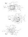
- FIG. 1shows an embodiment of a structural element in accordance with the invention shown in profile view, said structural element forming part of an anti-torque rotor of the Fenestron kind;
- FIG. 2is a perspective view of a structural element forming part of an anti-torque rotor of the Fenestron kind, with discontinuous perturbed shapes and also undulations extending transversely continuously from one trailing edge to the other; and
- FIG. 3shows another embodiment of a structural element in accordance with the invention in a perspective view, said structural element forming part of an anti-torque rotor of the Fenestron kind, with certain discontinuous perturbed shapes and/or continuous undulations from one trailing edge to the other forming an angle of orientation that is radial relative to a longitudinal direction of the structural element and thus of the aircraft that is fitted therewith.
- FIG. 1shows an embodiment of a structural element in accordance with the invention in profile view, said structural element forming part of an anti-torque rotor of the Fenestron kind.
- the Fenestron structurecomprises a fairing 1 having a rear portion 2 that is substantially orthogonal to the longitudinal direction L of the aircraft.
- the rear portion 2extends between two mutually spaced-apart trailing edges 3 and 4 .
- the fairing 1thus presents a determined width, said rear portion 2 closing at least part of the internal volume defined by the fairing 1 and generating aerodynamic drag in forward flight.
- the rear portion 2presents, at least in its trailing edges 3 and 4 , a perturbed shape 14 on the air-flow streamlines 5 as represented by arrows in FIG. 1 .
- the fairing 1advantageously includes a vertical tail fin 6 , and it extends around a hub 7 having blades 8 mounted thereon to constitute the anti-torque rotor of the Fenestron kind.
- the perturbed shape of the rear portion 2includes projecting and recessed portions in relief extending over the entire surface of the rear portion that is located between the trailing edges 3 and 4 .
- FIG. 2shows an embodiment of a structural element in accordance with the invention shown in perspective view, said structural element forming part of an anti-torque rotor of the Fenestron kind.
- the shape of the projecting and recessed orifices in reliefconstitutes undulations 9 of regular dimensions.
- the projecting and recessed portions in reliefpresent a shape constituting undulations 9 that are irregular in dimensions (not shown).
- At least some of the undulations 9extend from one trailing edge 3 to the other trailing edge 4 .
- At least some of the undulations 9extend from a trailing edge 3 or 4 to at least one intermediate zone of the rear portion 2 , said at least one intermediate zone 18 being located between the two trailing edges 3 and 4 .
- FIG. 3shows another embodiment of a structural element in accordance with the invention in a perspective view, said structural element forming part of an anti-torque rotor of the Fenestron kind
- the perturbed shape 14comprises protrusions 10 along each trailing edge 3 and 4 and on either side of an intermediate zone 18 .
- the protrusions 10are located in the vicinity of each trailing edge 3 and 4 and preferably astride the trailing edges 3 , 4 and the rear portion 2 .
- the undulationsmay thus be of short length and remain in the vicinity of the trailing edge, thus making it possible to arranged them on the high and low portions of the rear portion.
- some of the discontinuous perturbed shapes 15 , 16 and/or some of the continuous undulations extending from edge to edgeare not “horizontal”, but are rather oriented in a manner that is distributed radially.
- the longitudinal direction Lis horizontal.
- the transverse span of the fairing 1defines a transverse direction T that is also assumed to be horizontal. It is in the transverse direction T that the span of the fairing 1 extends.
- the longitudinal direction L and the transverse direction Tdefine an attitude plane (L, T).
- each discontinuous perturbed shape and/or each continuous undulationextends in an orientation eigenplane (i.e. a proper orientation plane) referenced R in FIGS. 2 and 3 .
- orientation eigenplane R of a discontinuous perturbed shape and/or each continuous undulationis parallel to the transverse direction T, but forms a radial orientation angle A relative to the attitude plane (L, T).
- discontinuous perturbed shapes and/or continuous undulationsform a radial orientation angle A that is said to be increasing, as shown in
- Such an increasing radial orientation angle Ais such that going from the front towards the rear of the fairing 1 , the orientation eigenplane R that intersects the attitude plane (L, T) towards the front of the fairing 1 becomes ever more distant from the attitude plane (L, T) towards the rear of the fairing 1 and towards the top of the fairing 1 .
- a radial orientation angle Athat is said to be decreasing, as in FIG. 3 .
- Such a decreasing radial orientation angle Ais such that from the front towards the rear of the fairing 1 , the orientation eigenplane R still intersects the attitude plane (L, T) towards the front of the fairing 1 , and becomes ever more distant from the attitude plane (L, T) towards the rear of the fairing 1 , but on going towards the bottom of the fairing 1 .
- protrusionsmay also be provided on all of the visible edges.
- the perturbed shapeincludes cavities 17 along each trailing edge 3 , 4 and preferably astride the trailing edges 3 , 4 and the rear portion 2 .
- the fairing 1 in accordance with the inventionmay also be any component part of a structural element for an aircraft that does not constitute an airfoil surface.
- the inventionalso applies to a ducted anti-torque tail rotor for a rotary wing aircraft, in particular for a helicopter.
- the structural elementincludes a hub 7 having blades 8 mounted thereon, means for driving the hub in rotation, and means for adjusting the blades.
- a rotorincludes the fairing 1 as described above.
- the fairing 1has two open side portions 11 and 12 that are substantially parallel, and that are situated on either side of the hub 7 ( FIG. 2 ). Each of the open side portions 11 and 12 is terminated towards the rear by a respective trailing edge 3 or 4 , and the rear portion 2 of the fairing 1 forms a clearly-defined base extending between said trailing edges 3 and 4 .
- the base-forming rear portion 2presents at least one curvature in a vertical and longitudinal plane of the aircraft.
- the shape of the fairing 1 in accordance with the inventionserves to excite instabilities in the air vortices 13 in the span of the base-forming rear portion 2 . These transverse instabilities accelerate dissipation of the wake, and thus reduce the average size of the separated zone. This reduction in the length of the average separation has the effect of reducing the aerodynamic drag due to the shape of the fairing 1 .
- average separationmay be defined in the present invention as the average length of the zone in which vortices are concentrated.
- the average separationis the separation shape that appears on calculating or measuring in the units, the mean field in flow. For example, it is possible to measure speeds in the wake and calculate their mean value at each three-dimensional point in the wake. This produces a time-averaged shape for the wake. When there is a base, this may generally represent one or two large vortices that are then referred to as average separations.
Landscapes
- Engineering & Computer Science (AREA)
- Aviation & Aerospace Engineering (AREA)
- Mechanical Engineering (AREA)
- Physics & Mathematics (AREA)
- Fluid Mechanics (AREA)
- Laminated Bodies (AREA)
- Turbine Rotor Nozzle Sealing (AREA)
Abstract
Description
Claims (20)
Applications Claiming Priority (2)
| Application Number | Priority Date | Filing Date | Title |
|---|---|---|---|
| FR1004748AFR2968272B1 (en) | 2010-12-06 | 2010-12-06 | IMPROVED STRUCTURE ELEMENT OF A GIRAVION TO DECREASE AERODYNAMIC TRAINING. |
| FR1004748 | 2010-12-06 |
Publications (2)
| Publication Number | Publication Date |
|---|---|
| US20120138731A1 US20120138731A1 (en) | 2012-06-07 |
| US8827201B2true US8827201B2 (en) | 2014-09-09 |
Family
ID=44170523
Family Applications (1)
| Application Number | Title | Priority Date | Filing Date |
|---|---|---|---|
| US13/307,448Expired - Fee RelatedUS8827201B2 (en) | 2010-12-06 | 2011-11-30 | Rotorcraft structural element for reducing aerodynamic drag |
Country Status (4)
| Country | Link |
|---|---|
| US (1) | US8827201B2 (en) |
| EP (1) | EP2460720B1 (en) |
| KR (1) | KR20120062627A (en) |
| FR (1) | FR2968272B1 (en) |
Cited By (5)
| Publication number | Priority date | Publication date | Assignee | Title |
|---|---|---|---|---|
| US20150217851A1 (en)* | 2012-08-16 | 2015-08-06 | Richard Kelso | Wing configuration |
| WO2016118180A1 (en)* | 2015-01-20 | 2016-07-28 | Carson Franklin D | Rotary-wing aircraft with ducted anti-torque device |
| US9475578B2 (en) | 2013-12-10 | 2016-10-25 | Airbus Helicopters Deutschland GmbH | Rotary wing aircraft with a tail shroud |
| US20190308722A1 (en)* | 2018-04-10 | 2019-10-10 | Bell Helicopter Textron Inc. | Tail rotor housing |
| US20240253776A1 (en)* | 2023-01-26 | 2024-08-01 | Subaru Corporation | Helicopter |
Families Citing this family (3)
| Publication number | Priority date | Publication date | Assignee | Title |
|---|---|---|---|---|
| FR3013677B1 (en) | 2013-11-27 | 2015-12-04 | Eurocopter France | GIRAVION TOP SIDE COMPRISING A TRUNK WATER DROP PROFILE HAVING A SURFACE SURFACE MISFEED |
| PL3061689T3 (en) | 2015-02-27 | 2018-01-31 | Airbus Helicopters Deutschland GmbH | Tail assembly for a rotorcraft, rotorcraft and method of manufacture of a strengthened tail assembly |
| FR3075757B1 (en)* | 2017-12-22 | 2019-11-15 | Airbus Helicopters | AERODYNAMIC WRAPPED AERODYNAMIC ENVELOPES FOR BLADE COLLARS AND BLADE SLEEPING OF A ROTOR OF AN AIRCRAFT |
Citations (36)
| Publication number | Priority date | Publication date | Assignee | Title |
|---|---|---|---|---|
| US2074201A (en)* | 1934-01-29 | 1937-03-16 | Avions Kellner Bechereau Soc | Airfoil used in aeronautics |
| GB577524A (en) | 1943-06-04 | 1946-05-21 | Enea Bossi | Improvement in airing of anti-torque propeller |
| US3463418A (en)* | 1968-03-20 | 1969-08-26 | Edmond S Miksch | Vortex generator for airplane wing |
| US3506219A (en)* | 1966-12-13 | 1970-04-14 | Sud Aviat Soc Nationale De Con | Helicopter steering and propelling device |
| US3578264A (en)* | 1968-07-09 | 1971-05-11 | Battelle Development Corp | Boundary layer control of flow separation and heat exchange |
| US4343506A (en)* | 1980-08-05 | 1982-08-10 | The United States Of America As Represented By The Administrator Of The National Aeronautics And Space Administration | Low-drag ground vehicle particularly suited for use in safely transporting livestock |
| US4455045A (en)* | 1981-10-26 | 1984-06-19 | Wheeler Gary O | Means for maintaining attached flow of a flowing medium |
| US4718620A (en)* | 1984-10-15 | 1988-01-12 | Braden John A | Terraced channels for reducing afterbody drag |
| US4776535A (en)* | 1986-12-29 | 1988-10-11 | United Technologies Corporation | Convoluted plate to reduce base drag |
| US4809931A (en)* | 1986-06-16 | 1989-03-07 | Aerospatiale, Societe Nationale Industrielle | Directional and stabilizing device having a faired and slanted antitorque rotor and a disymmetric "V" empennage, and a helicopter equipped with such a device |
| US4813635A (en)* | 1986-12-29 | 1989-03-21 | United Technologies Corporation | Projectile with reduced base drag |
| US4830315A (en)* | 1986-04-30 | 1989-05-16 | United Technologies Corporation | Airfoil-shaped body |
| US4986496A (en)* | 1985-05-31 | 1991-01-22 | Minnesota Mining And Manufacturing | Drag reduction article |
| US5058837A (en)* | 1989-04-07 | 1991-10-22 | Wheeler Gary O | Low drag vortex generators |
| US5102067A (en)* | 1991-04-11 | 1992-04-07 | United Technologies Corporation | Integrated helicopter empennage structure |
| US5108044A (en)* | 1991-04-11 | 1992-04-28 | United Technologies Corporation | Shroud-fin integration shelf for a helicopter empennage structure |
| US5131604A (en)* | 1991-04-11 | 1992-07-21 | United Technologies Corporation | Helicopter antitorque device |
| US5133516A (en)* | 1985-05-31 | 1992-07-28 | Minnesota Mining And Manufacturing Co. | Drag reduction article |
| US5289997A (en)* | 1991-04-18 | 1994-03-01 | Harris B Waylon | Apparatus and method for reducing drag on bodies moving through fluid |
| US5454691A (en)* | 1994-05-04 | 1995-10-03 | Eurocopter France | Flow-straightener vane for counter-torque device with ducted rotor and ducted flow-straightening stator, for helicopter |
| EP0724691A1 (en) | 1993-10-20 | 1996-08-07 | Josef Moser | Surface of a body immersed in a fluid flow |
| US5566907A (en)* | 1994-05-04 | 1996-10-22 | Eurocopter France | Counter-torque device with ducted rotor and phase modulation of the blades, for helicopter |
| US5588618A (en)* | 1994-05-04 | 1996-12-31 | Eurocopter France | Counter-torque device with rotor and flow-straightening stator, both of which are ducted, and phase modulation of the blades of the rotor, for helicopter |
| US5634611A (en)* | 1994-05-04 | 1997-06-03 | Eurocopter France | Counter-torque device with rotor and flow straightening stator, both of which are ducted, and inclined flow-straightening vanes |
| US5810285A (en)* | 1996-12-20 | 1998-09-22 | Sikorsky Aircraft Corporation | Drive shaft casing for a ducted fan anti-torque device |
| US5833389A (en)* | 1996-12-09 | 1998-11-10 | Orlev Scientific Computing Ltd. | Apparatus for controlling turbulence in boundary layer and other wall-bounded fluid flow fields |
| JP2000155496A (en) | 1998-11-24 | 2000-06-06 | Ricoh Co Ltd | Fixing device |
| JP2000255496A (en)* | 1999-03-09 | 2000-09-19 | Mitsubishi Heavy Ind Ltd | Tail rotor shroud |
| US6345791B1 (en)* | 2000-04-13 | 2002-02-12 | Lockheed Martin Corporation | Streamwise variable height riblets for reducing skin friction drag of surfaces |
| US6634700B1 (en)* | 2002-08-02 | 2003-10-21 | 5 Star Product Design & Development Group, Inc. | Aerodynamic trailer |
| EP1527992A2 (en) | 2003-11-03 | 2005-05-04 | Patria Finavicomp Oy | Arrangement for generating vortexes |
| US6959958B2 (en)* | 2000-06-09 | 2005-11-01 | Basford William C | Aerodynamic combination for improved base drag reduction |
| US7255387B2 (en)* | 2003-08-21 | 2007-08-14 | Solus Solutions And Technologies, Llc | Vortex strake device and method for reducing the aerodynamic drag of ground vehicles |
| US20080217484A1 (en) | 2006-11-14 | 2008-09-11 | Airbus Deutschland Gmbh | Brake flap for an aircraft |
| US20090236872A1 (en)* | 2008-03-21 | 2009-09-24 | Solus-Solutions And Technologies Llc | Outboard wake stabilization device and method for reducing the aerodynamic drag of ground vehicles |
| US7676923B2 (en)* | 2004-12-16 | 2010-03-16 | Eurocopter | Method and apparatus for manufacturing a helicopter rotor fairing, and a fairing obtained thereby |
Family Cites Families (1)
| Publication number | Priority date | Publication date | Assignee | Title |
|---|---|---|---|---|
| FR1004748A (en) | 1949-12-30 | 1952-04-02 | Improvements to shoes |
- 2010
- 2010-12-06FRFR1004748Apatent/FR2968272B1/enactiveActive
- 2011
- 2011-11-16EPEP11009080.0Apatent/EP2460720B1/enactiveActive
- 2011-11-30USUS13/307,448patent/US8827201B2/ennot_activeExpired - Fee Related
- 2011-12-02KRKR1020110128348Apatent/KR20120062627A/ennot_activeCeased
Patent Citations (40)
| Publication number | Priority date | Publication date | Assignee | Title |
|---|---|---|---|---|
| US2074201A (en)* | 1934-01-29 | 1937-03-16 | Avions Kellner Bechereau Soc | Airfoil used in aeronautics |
| GB577524A (en) | 1943-06-04 | 1946-05-21 | Enea Bossi | Improvement in airing of anti-torque propeller |
| US3506219A (en)* | 1966-12-13 | 1970-04-14 | Sud Aviat Soc Nationale De Con | Helicopter steering and propelling device |
| US3463418A (en)* | 1968-03-20 | 1969-08-26 | Edmond S Miksch | Vortex generator for airplane wing |
| US3578264B1 (en)* | 1968-07-09 | 1991-11-19 | Univ Michigan | |
| US3578264A (en)* | 1968-07-09 | 1971-05-11 | Battelle Development Corp | Boundary layer control of flow separation and heat exchange |
| US4343506A (en)* | 1980-08-05 | 1982-08-10 | The United States Of America As Represented By The Administrator Of The National Aeronautics And Space Administration | Low-drag ground vehicle particularly suited for use in safely transporting livestock |
| US4455045A (en)* | 1981-10-26 | 1984-06-19 | Wheeler Gary O | Means for maintaining attached flow of a flowing medium |
| US4718620A (en)* | 1984-10-15 | 1988-01-12 | Braden John A | Terraced channels for reducing afterbody drag |
| US5069403A (en)* | 1985-05-31 | 1991-12-03 | Minnesota Mining And Manufacturing Company | Drag reduction article |
| US4986496A (en)* | 1985-05-31 | 1991-01-22 | Minnesota Mining And Manufacturing | Drag reduction article |
| US5133516A (en)* | 1985-05-31 | 1992-07-28 | Minnesota Mining And Manufacturing Co. | Drag reduction article |
| US4830315A (en)* | 1986-04-30 | 1989-05-16 | United Technologies Corporation | Airfoil-shaped body |
| US4809931A (en)* | 1986-06-16 | 1989-03-07 | Aerospatiale, Societe Nationale Industrielle | Directional and stabilizing device having a faired and slanted antitorque rotor and a disymmetric "V" empennage, and a helicopter equipped with such a device |
| US4813635A (en)* | 1986-12-29 | 1989-03-21 | United Technologies Corporation | Projectile with reduced base drag |
| US4776535A (en)* | 1986-12-29 | 1988-10-11 | United Technologies Corporation | Convoluted plate to reduce base drag |
| US5058837A (en)* | 1989-04-07 | 1991-10-22 | Wheeler Gary O | Low drag vortex generators |
| US5102067A (en)* | 1991-04-11 | 1992-04-07 | United Technologies Corporation | Integrated helicopter empennage structure |
| US5108044A (en)* | 1991-04-11 | 1992-04-28 | United Technologies Corporation | Shroud-fin integration shelf for a helicopter empennage structure |
| US5131604A (en)* | 1991-04-11 | 1992-07-21 | United Technologies Corporation | Helicopter antitorque device |
| US5289997A (en)* | 1991-04-18 | 1994-03-01 | Harris B Waylon | Apparatus and method for reducing drag on bodies moving through fluid |
| EP0724691A1 (en) | 1993-10-20 | 1996-08-07 | Josef Moser | Surface of a body immersed in a fluid flow |
| US5860626A (en)* | 1993-10-20 | 1999-01-19 | Moser; Josef | Surface of a body exposed to circumfluent fluid |
| US5454691A (en)* | 1994-05-04 | 1995-10-03 | Eurocopter France | Flow-straightener vane for counter-torque device with ducted rotor and ducted flow-straightening stator, for helicopter |
| US5566907A (en)* | 1994-05-04 | 1996-10-22 | Eurocopter France | Counter-torque device with ducted rotor and phase modulation of the blades, for helicopter |
| US5588618A (en)* | 1994-05-04 | 1996-12-31 | Eurocopter France | Counter-torque device with rotor and flow-straightening stator, both of which are ducted, and phase modulation of the blades of the rotor, for helicopter |
| US5634611A (en)* | 1994-05-04 | 1997-06-03 | Eurocopter France | Counter-torque device with rotor and flow straightening stator, both of which are ducted, and inclined flow-straightening vanes |
| US5833389A (en)* | 1996-12-09 | 1998-11-10 | Orlev Scientific Computing Ltd. | Apparatus for controlling turbulence in boundary layer and other wall-bounded fluid flow fields |
| US5810285A (en)* | 1996-12-20 | 1998-09-22 | Sikorsky Aircraft Corporation | Drive shaft casing for a ducted fan anti-torque device |
| JP2000155496A (en) | 1998-11-24 | 2000-06-06 | Ricoh Co Ltd | Fixing device |
| JP2000255496A (en)* | 1999-03-09 | 2000-09-19 | Mitsubishi Heavy Ind Ltd | Tail rotor shroud |
| US6345791B1 (en)* | 2000-04-13 | 2002-02-12 | Lockheed Martin Corporation | Streamwise variable height riblets for reducing skin friction drag of surfaces |
| US6959958B2 (en)* | 2000-06-09 | 2005-11-01 | Basford William C | Aerodynamic combination for improved base drag reduction |
| US6634700B1 (en)* | 2002-08-02 | 2003-10-21 | 5 Star Product Design & Development Group, Inc. | Aerodynamic trailer |
| US7255387B2 (en)* | 2003-08-21 | 2007-08-14 | Solus Solutions And Technologies, Llc | Vortex strake device and method for reducing the aerodynamic drag of ground vehicles |
| EP1527992A2 (en) | 2003-11-03 | 2005-05-04 | Patria Finavicomp Oy | Arrangement for generating vortexes |
| US7275721B2 (en)* | 2003-11-03 | 2007-10-02 | Patria Finavicomp Oy | Arrangement for generating vortexes |
| US7676923B2 (en)* | 2004-12-16 | 2010-03-16 | Eurocopter | Method and apparatus for manufacturing a helicopter rotor fairing, and a fairing obtained thereby |
| US20080217484A1 (en) | 2006-11-14 | 2008-09-11 | Airbus Deutschland Gmbh | Brake flap for an aircraft |
| US20090236872A1 (en)* | 2008-03-21 | 2009-09-24 | Solus-Solutions And Technologies Llc | Outboard wake stabilization device and method for reducing the aerodynamic drag of ground vehicles |
Non-Patent Citations (3)
| Title |
|---|
| Korean Office Action Dated Sep. 5, 2013 ,Application No. 10-2011-0128348, Applicant Eurocopter, 7 Pages. |
| Near-Wake Flow Dynamics Resulting from Trailing Edge Spanwise Perturbation. Hangan and Naughton. Published by the American Institute of Aeronautics and Astronautics, pp. 1-9, 2008. |
| Search Report and Written Opinion; Application No. FR. 1004748; dated Jul. 4, 2011. |
Cited By (6)
| Publication number | Priority date | Publication date | Assignee | Title |
|---|---|---|---|---|
| US20150217851A1 (en)* | 2012-08-16 | 2015-08-06 | Richard Kelso | Wing configuration |
| US9475578B2 (en) | 2013-12-10 | 2016-10-25 | Airbus Helicopters Deutschland GmbH | Rotary wing aircraft with a tail shroud |
| WO2016118180A1 (en)* | 2015-01-20 | 2016-07-28 | Carson Franklin D | Rotary-wing aircraft with ducted anti-torque device |
| US20190308722A1 (en)* | 2018-04-10 | 2019-10-10 | Bell Helicopter Textron Inc. | Tail rotor housing |
| US10814971B2 (en)* | 2018-04-10 | 2020-10-27 | Textron Innovations Inc. | Tail rotor housing |
| US20240253776A1 (en)* | 2023-01-26 | 2024-08-01 | Subaru Corporation | Helicopter |
Also Published As
| Publication number | Publication date |
|---|---|
| FR2968272B1 (en) | 2013-07-12 |
| US20120138731A1 (en) | 2012-06-07 |
| EP2460720A1 (en) | 2012-06-06 |
| KR20120062627A (en) | 2012-06-14 |
| FR2968272A1 (en) | 2012-06-08 |
| EP2460720B1 (en) | 2016-03-30 |
Similar Documents
| Publication | Publication Date | Title |
|---|---|---|
| US8827201B2 (en) | Rotorcraft structural element for reducing aerodynamic drag | |
| US6431498B1 (en) | Scalloped wing leading edge | |
| US20110006165A1 (en) | Application of conformal sub boundary layer vortex generators to a foil or aero/ hydrodynamic surface | |
| CN107757879B (en) | Wingtip device for a wing of an aircraft, aircraft and use | |
| US8066219B2 (en) | Anhedral tip blades for tiltrotor aircraft | |
| US20150217851A1 (en) | Wing configuration | |
| AU637564B2 (en) | Shroud-fin integration shelf for a helicopter empennage structure | |
| US20180304997A1 (en) | Split Winglet | |
| US11447243B2 (en) | Helicopter with anti-torque system, related kit and methods | |
| US9475578B2 (en) | Rotary wing aircraft with a tail shroud | |
| KR102279988B1 (en) | A rotorcraft with a stabilizer wing | |
| EP2604516B1 (en) | Minimally intrusive wingtip vortex wake mitigation using microvane arrays | |
| KR20200055036A (en) | Aircraft cupola pairing and method for manufacturing same | |
| JP5313884B2 (en) | Aircraft equipped with a device for reducing induced drag | |
| US20220297829A1 (en) | Lift enhancement assembly of an aerial vehicle with fixed wings | |
| JP2009538773A (en) | Method and apparatus for generating aerodynamic resistance in an aircraft | |
| CN112849388A (en) | Transonic buffeting control structure based on wing trailing edge vent hole | |
| US12043372B1 (en) | Micro-cavity actuator for delay of dynamic stall | |
| KR102027226B1 (en) | Aircraft rotor blade sleeves with projections in the rear zone, and rotors provided with such sleeves | |
| EP1568604B1 (en) | Helicopter | |
| CN119460075A (en) | Airfoil of a lifting element of an aircraft |
Legal Events
| Date | Code | Title | Description |
|---|---|---|---|
| AS | Assignment | Owner name:EUROCOPTER, FRANCE Free format text:ASSIGNMENT OF ASSIGNORS INTEREST;ASSIGNOR:ALFANO, DAVID;REEL/FRAME:027299/0151 Effective date:20111121 | |
| AS | Assignment | Owner name:AIRBUS HELICOPTERS, FRANCE Free format text:CHANGE OF NAME;ASSIGNOR:EUROCOPTER;REEL/FRAME:032813/0001 Effective date:20140107 | |
| STCF | Information on status: patent grant | Free format text:PATENTED CASE | |
| FEPP | Fee payment procedure | Free format text:PAYOR NUMBER ASSIGNED (ORIGINAL EVENT CODE: ASPN); ENTITY STATUS OF PATENT OWNER: LARGE ENTITY | |
| MAFP | Maintenance fee payment | Free format text:PAYMENT OF MAINTENANCE FEE, 4TH YEAR, LARGE ENTITY (ORIGINAL EVENT CODE: M1551) Year of fee payment:4 | |
| FEPP | Fee payment procedure | Free format text:MAINTENANCE FEE REMINDER MAILED (ORIGINAL EVENT CODE: REM.); ENTITY STATUS OF PATENT OWNER: LARGE ENTITY | |
| LAPS | Lapse for failure to pay maintenance fees | Free format text:PATENT EXPIRED FOR FAILURE TO PAY MAINTENANCE FEES (ORIGINAL EVENT CODE: EXP.); ENTITY STATUS OF PATENT OWNER: LARGE ENTITY | |
| STCH | Information on status: patent discontinuation | Free format text:PATENT EXPIRED DUE TO NONPAYMENT OF MAINTENANCE FEES UNDER 37 CFR 1.362 | |
| FP | Lapsed due to failure to pay maintenance fee | Effective date:20220909 |