US8827180B2 - Agricultural sprayer boom having aligned mast and center section - Google Patents
Agricultural sprayer boom having aligned mast and center sectionDownload PDFInfo
- Publication number
- US8827180B2 US8827180B2US13/097,327US201113097327AUS8827180B2US 8827180 B2US8827180 B2US 8827180B2US 201113097327 AUS201113097327 AUS 201113097327AUS 8827180 B2US8827180 B2US 8827180B2
- Authority
- US
- United States
- Prior art keywords
- frame
- mast
- center section
- boom assembly
- agricultural sprayer
- Prior art date
- Legal status (The legal status is an assumption and is not a legal conclusion. Google has not performed a legal analysis and makes no representation as to the accuracy of the status listed.)
- Active, expires
Links
Images


Classifications
- A—HUMAN NECESSITIES
- A01—AGRICULTURE; FORESTRY; ANIMAL HUSBANDRY; HUNTING; TRAPPING; FISHING
- A01M—CATCHING, TRAPPING OR SCARING OF ANIMALS; APPARATUS FOR THE DESTRUCTION OF NOXIOUS ANIMALS OR NOXIOUS PLANTS
- A01M7/00—Special adaptations or arrangements of liquid-spraying apparatus for purposes covered by this subclass
- A01M7/005—Special arrangements or adaptations of the spraying or distributing parts, e.g. adaptations or mounting of the spray booms, mounting of the nozzles, protection shields
- A01M7/0053—Mounting of the spraybooms
- A—HUMAN NECESSITIES
- A01—AGRICULTURE; FORESTRY; ANIMAL HUSBANDRY; HUNTING; TRAPPING; FISHING
- A01M—CATCHING, TRAPPING OR SCARING OF ANIMALS; APPARATUS FOR THE DESTRUCTION OF NOXIOUS ANIMALS OR NOXIOUS PLANTS
- A01M7/00—Special adaptations or arrangements of liquid-spraying apparatus for purposes covered by this subclass
- A01M7/005—Special arrangements or adaptations of the spraying or distributing parts, e.g. adaptations or mounting of the spray booms, mounting of the nozzles, protection shields
- A01M7/0071—Construction of the spray booms
Definitions
- the inventionrelates generally to agricultural equipment, and more specifically, to a sprayer boom having an aligned mast and center section.
- Such agricultural vehiclestypically include a boom configured to facilitate product delivery over wide swaths of soil.
- the boomis suspended from a rear frame of the vehicle, and extends laterally outward from a center section.
- the center sectionis supported by a mast that is coupled to the agricultural vehicle by a linkage assembly.
- the center sectionmay be positioned behind the mast, and suspended from the mast via a linkage configured to facilitate rotation of the center section relative to the mast.
- the center sectionis positioned behind the mast, the weight of the boom applies a torque to the mast, the linkage assembly and the rear frame of the vehicle.
- the center section, the mast, the linkage assembly and the rear framemay employ stronger structural members and/or additional structural members to resist the torque, thereby increasing the weight of the components. Consequently, larger/more powerful vehicles are employed to accommodate the increased load. Unfortunately, the acquisition and operating costs of the larger/more powerful vehicles significantly increases the overhead associated with crop production. In addition, the increased vehicle load may result in undesirable soil compaction.
- the present inventionprovides an agricultural sprayer boom assembly including a center section having a first frame configured to support left and right wing sections of the agricultural sprayer boom assembly.
- the agricultural sprayer boom assemblyalso includes a mast having a second frame coupled to the first frame, and configured to support the first frame during operation and transport.
- the first and second framesare aligned with one another along a direction of travel.
- the torque applied to the mast by the center sectionis substantially less than the torque applied by a center section positioned behind the mast. Consequently, the center section and the mast may employ lighter structural members and/or fewer structural members to resist the torque, thereby decreasing the weight of the boom assembly.
- the lighter weightreduces soil compaction and/or facilitates the use of smaller/less powerful vehicles to transport the boom assembly across a field, thereby reducing overhead costs associated with crop production.
- FIG. 1is a perspective view of an embodiment of an agricultural vehicle having a boom assembly that may include an aligned mast and center section;
- FIG. 2is a front view of an embodiment of a boom assembly that may be employed within the agricultural vehicle of FIG. 1 ;
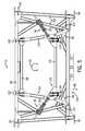
- FIG. 3is a perspective view of an embodiment of a mast and a center section having respective frames aligned with one another along a direction of travel;
- FIG. 4is a side view of the mast and center section shown in FIG. 3 ;
- FIG. 5is a front view of the mast and center section shown in FIG. 3 .
- FIG. 1is a perspective view of an embodiment of an agricultural vehicle 10 having a boom assembly 12 that may include an aligned mast and center section.
- the agricultural vehicle 10includes a tank 14 where materials, such as fertilizer, pesticide, herbicide, and/or other products, are stored for distribution to a field.
- the agricultural vehicle 10also includes a frame 16 , a cab 18 , and a hood 20 .
- the frame 16provides structural support for the cab 18 , the hood 20 , and the tank 14 .
- the cab 18provides an enclosed space for an operator, and the hood 20 houses the engine and/or systems configured to facilitate operation of the vehicle 10 .
- the agricultural vehicle 10also includes wheels 22 configured to support the frame 16 , and to facilitate movement of the vehicle across the field.
- the boom assembly 12includes a mast 24 that supports the weight of the boom, and facilitates rotation of the boom relative to the vehicle 10 .
- the mast 24is coupled to the agricultural vehicle 10 by a linkage assembly (e.g., parallel linkage, four-bar linkage, etc.) that facilitates height adjustment of the boom relative to the soil surface.
- a linkage assemblye.g., parallel linkage, four-bar linkage, etc.
- the boomextends laterally outward from the agricultural vehicle 10 to cover wide swaths of soil, as illustrated.
- each lateral wing of the boom assembly 12may be folded forwardly or rearwardly into a transport position, thereby reducing the overall width of the vehicle.
- the boom assembly 12includes a center section having a frame configured to support left and right wing sections of the agricultural sprayer boom.
- the mast 24includes a frame coupled to the center section frame, and configured to support the center section during operation and transport.
- the center section frame and the mast frameare aligned with one another along a direction of travel.
- the torque applied to the mast by the center sectionis substantially less than the torque applied by a center section positioned behind the mast. Consequently, the center section and the mast may employ lighter structural members and/or fewer structural members to resist the torque, thereby decreasing the weight of the boom assembly 12 .
- the reduced weight of the boom assembly 12decreases the load applied to the vehicle 10 , thereby reducing soil compaction and/or facilitating the use of smaller/less powerful vehicles. Due to the decreased acquisition and operating costs of the smaller/less powerful vehicles, the overhead associated with crop production may be significantly reduced.
- FIG. 2is a front view of an embodiment of a boom assembly 12 that may be employed within the agricultural vehicle 10 of FIG. 1 .
- the boom assembly 12includes a center section 40 , a first (e.g., left) wing assembly 42 , and a second (e.g., right) wing assembly 44 .
- the center section 40is configured to couple to the frame 16 of the agricultural vehicle 10 via the mast 24 and a linkage assembly 46 .
- the center section 40is configured to support the wing assemblies 42 and 44 during operation and transport. As illustrated, the wing assemblies 42 and 44 are coupled to opposite lateral sides of the center section 40 .
- an inner section 48 of the first wing assembly 42is pivotally coupled to one lateral side of the center section 40
- an inner section 50 of the second wing assembly 44is coupled to an opposite lateral side of the center section 40 .
- the wing assemblies 42 and 44may be folded forwardly or rearwardly from the illustrated working position to a transport position that reduces the overall width of the vehicle.
- the first wing assembly 42includes an actuating cylinder 52 (e.g., electromechanical actuator, hydraulic cylinder and/or pneumatic cylinder) extending between the inner section 48 and the center section 40 .
- the cylinder 52may be fluidly coupled to a fluid power supply that provides pressurized fluid to drive a piston rod to extend and retract.
- the fluid power supplymay be hydraulic or pneumatic, thereby powering a corresponding hydraulic or pneumatic cylinder 52 .
- extension of the piston roddrives the first wing assembly 42 into the illustrated working position, and retraction of the piston rod drives the first wing assembly 42 into the transport position. That is, retraction of the piston rod induces the first wing assembly 42 to rotate forwardly about a pivot, thereby reducing the overall width of the vehicle 10 .
- the first wing assembly 42also includes an outer portion 54 having an actuating cylinder 56 .
- the outer portion 54is coupled to the inner section 48 by a pivotal joint.
- the actuating cylinder 56may be a hydraulic and/or pneumatic cylinder configured to displace a piston rod extending from the cylinder 56 . Retracting the piston rod of the cylinder 56 will cause the outer portion 54 to rotate upwardly from the illustrated product distribution/working position to a transport position.
- the outer portion 54includes an outer section 58 , a breakaway section 60 , and a biasing member 62 .
- the outer section 58extends between the inner section 48 and the breakaway section 60 .
- the breakaway section 60is pivotally coupled to the outer section 58 by a joint, and the biasing member 62 is configured to urge the breakaway section 60 toward the illustrated working position. In this configuration, contact between the breakaway section 60 and an obstruction will drive the breakaway section to rotate. After the boom has passed the obstruction, the biasing member 62 will urge the breakaway section back to the working position.
- the structure of the second wing assembly 44is similar to the structure of the first wing assembly 42 .
- the second wing assembly 44includes an actuating cylinder 64 (e.g., electromechanical actuator, hydraulic cylinder and/or pneumatic cylinder) extending between the inner section 50 and the center section 40 .
- the cylinder 64may be fluidly coupled to a fluid power supply that provides pressurized fluid to drive a piston rod to extend and retract.
- the fluid power supplymay be hydraulic or pneumatic, thereby powering a corresponding hydraulic or pneumatic cylinder 64 .
- extension of the piston roddrives the second wing assembly 44 into the illustrated working position, and retraction of the piston rod drives the second wing assembly 44 into the transport position. That is, retraction of the piston rod induces the second wing assembly 44 to rotate forwardly about a pivot, thereby reducing the overall width of the vehicle 10 .
- the second wing assembly 44also includes an outer portion 66 having an actuating cylinder 68 .
- the outer portion 66is coupled to the inner section 50 by a pivotal joint.
- the actuating cylinder 68may be a hydraulic and/or pneumatic cylinder configured to displace a piston rod extending from the cylinder 68 . Retracting the piston rod of the cylinder 68 will cause the outer portion 66 to rotate upwardly from the illustrated product distribution/working position to a transport position.
- the outer portion 66includes an outer section 70 , a breakaway section 72 , and a biasing member 74 .
- the outer section 70extends between the inner section 50 and the breakaway section 72 .
- the breakaway section 72is pivotally coupled to the outer section 70 by a joint, and the biasing member 74 is configured to urge the breakaway section 72 toward the illustrated working position. In this configuration, contact between the breakaway section 72 and an obstruction will drive the breakaway section to rotate. After the boom has passed the obstruction, the biasing member 74 will urge the breakaway section back to the working position.
- a center section frameis aligned with a mast frame along the direction of travel (i.e., in a fore/aft direction).
- the torque applied to the mast by the boomis substantially less than the torque applied by a boom having a center section positioned behind the mast. Consequently, the center section, the mast, the linkage assembly and the vehicle frame may employ lighter structural members and/or fewer structural members to resist the torque, thereby decreasing the weight of the boom assembly and/or the vehicle frame.
- soil compactionwill be reduced and/or smaller/less powerful vehicles may be employed to transport the boom assembly across a field. Due to the reduced acquisition and operating costs of the smaller/less powerful vehicles, the overhead associated with crop production may be significantly decreased.
- FIG. 3is a perspective view of an embodiment of a mast 24 and a center section 40 having respective frames aligned with one another along a direction of travel.
- a linkage assembly 46extends between a mobile chassis (e.g., the frame 16 of the agricultural vehicle 10 ) and the mast 24 to support the mast, and to facilitate height adjustment of the mast relative to the soil surface.
- the linkage assembly 46includes an upper support 76 , a lower support 78 and actuating cylinders 80 .
- the upper support 76is pivotally coupled to an upper portion of the mast 24
- the lower support 78is pivotally coupled to a lower portion of the mast 24 .
- each actuating cylinder 80extends between a distal end of the lower support 78 and a base of the upper support 76 .
- extension of the cylinders 80will induce the supports 76 and 78 to rotate downwardly with respect to the mast 24 , thereby raising the mast 24 relative to the frame 16 .
- retraction of the cylinders 80will induce the supports 76 and 78 to rotate upwardly, thereby lowering the mast 24 relative to the frame 16 .
- the height of the boom relative to the soil surfacemay be particularly adjusted to accommodate various crops, soil conditions and/or delivered products, for example.
- the center section 40includes a frame 82 configured to support the left and right wing assemblies of the agricultural spray boom assembly 12 .
- the mast 24includes a frame 84 configured to support the center section frame 82 during operation and transport.
- the center section frame 82is coupled to the mast frame 84 via a linkage 86 configured to transfer the downward load 88 of the center section 40 to the mast 24 .
- the weight of the left and right wing assemblies 42 and 44is supported by the center section 40 , and the center section 40 transfers the load to the mast 24 via the linkage 86 .
- the mast 24transfers the load to the vehicle frame 16 via the linkage assembly 46 , thereby suspending the boom assembly 12 above the soil surface.
- the linkage 86facilitates rotation of the center section 40 relative to the mast 24 in a direction 90 (i.e., about an axis parallel to the direction of travel 92 ).
- the boommay remain substantially parallel to the soil surface despite movement of the vehicle 10 .
- the boom assembly 12includes a suspension 94 configured to damp rotary oscillations of the center section 40 relative to the mast 24 , thereby providing a stable platform for the spray nozzles.
- the center section 40includes multiple supports 96 coupled to the frame 82 , and configured to rotatably couple the left and right wing assemblies to the center section 40 .
- each support 96may include openings configured to receive a pin coupled to a respective wing assembly.
- the supports 96will bear the downward load 88 of the wing assemblies, while facilitating rotation of the wing assemblies between the working position and the transport position.
- the wing assembliesare configured to rotate forwardly to the transport position. While in the transport position, the wing assemblies will urge the center section 40 to rotate in a direction 98 about an axis 100 perpendicular to the direction of travel 92 .
- the mast 24includes multiple guides coupled to the frame 84 , and configured to interface with the center section frame 82 to block rotation of the center section 40 relative to the mast 24 about the axis 100 .
- the center section 40includes upper guides 102 coupled to an upper portion of the frame 82 , and lower guides 104 coupled to a lower portion of the frame 82 .
- the guides 102 and 104include liners 106 configured to facilitate lateral movement of the center section frame 82 as the center section 40 rotates relative to the mast 24 in the direction 90 . Accordingly, the guides 102 and 104 block rotation of the center section 40 in the direction 98 , while enabling the center section 40 to rotate in the direction 90 .
- the center section frame 82includes multiple structural elements (e.g., rectangular tubes) aligned with a first plane substantially perpendicular to the direction of travel 92
- the mast frame 84includes multiple structural elements (e.g., rectangular tubes) aligned with a second plane substantially perpendicular to the direction of travel 92 .
- the first and second planesare aligned with one another along the direction of travel 92 , thereby aligning the center section frame and the mast frame.
- the center section, the mast, the linkage assembly and the vehicle framemay employ lighter structural members and/or fewer structural members to resist the torque, thereby decreasing the weight of the boom assembly and/or the vehicle frame.
- soil compactionwill be reduced and/or smaller/less powerful vehicles may be employed to transport the boom assembly across a field. Due to the reduced acquisition and operating costs of the smaller/less powerful vehicles, the overhead associated with crop production may be significantly decreased.
- FIG. 4is a side view of the mast and center section shown in FIG. 3 .
- the center section 40includes supports 108 coupled to upper and lower portions of the frame 82 , and configured to provide enhanced structural rigidity.
- the wing assembliesurge the center section 40 to rotate in the direction 98 while the wing assemblies are in the transport position.
- the guides 102 and 104block rotation of the center section 40 relative to the mast 24 , thereby inducing a torque within the center section frame 82 .
- the supports 108are configured to resist the torque, thereby enabling the center section 40 to support the wing assemblies while the wing assemblies are in the transport position.
- the center section frame 82is aligned with the mast frame 84 along the direction of travel 92 .
- the mast frame 84does not extend past the center section frame 82 along an axis parallel to the direction of travel 92 . Consequently, the overall vehicle length may be significantly reduced, as compared to configurations in which the center section is positioned behind the mast.
- the overhung load on the linkage assembly 46 and/or the vehicle chassismay be significantly reduced. Therefore, the linkage assembly and/or vehicle chassis may include lighter and/or fewer structural elements, thereby reducing the overall weight of the agricultural vehicle.
- FIG. 5is a front view of the mast and center section shown in FIG. 3 .
- the center section frame 82is disposed about the mast frame 84 , and the frames are aligned with one another along the direction of travel.
- the mast frame 84includes multiple structural tubes 110 having substantially rectangular cross sections
- the center section frame 82includes multiple structural tubes 112 having substantially rectangular cross sections.
- the structural tubes 112 of the center section frame 82are aligned with a first plane substantially perpendicular to the direction of travel
- the structural tubes 110 of the mast frame 84are aligned with a second plane substantially perpendicular to the direction of travel.
- the first and second planesare aligned with one another along the direction of travel 92 , thereby aligning the center section frame and the mast frame in a fore/aft direction.
- the center section frame 82is coupled to the mast frame 84 via a linkage 86 configured to transfer the downward load 88 of the center section 40 to the mast 24 .
- the linkage 86includes multiple links 114 extending from a lower portion 116 of the mast frame 84 to a lower portion 118 of the center section frame 82 .
- the linkage 86facilitates rotation of the center section 40 relative to the mast 24 in a direction 90 .
- the boommay remain substantially parallel to the soil surface despite movement of the vehicle 10 .
- the suspension 94includes multiple springs 120 extending between the center section frame 82 and the mast frame 84 . The springs 120 are configured to damp rotary oscillations of the center section 40 relative to the mast 24 , thereby providing a stable platform for the spray nozzles.
Landscapes
- Life Sciences & Earth Sciences (AREA)
- Engineering & Computer Science (AREA)
- Insects & Arthropods (AREA)
- Pest Control & Pesticides (AREA)
- Wood Science & Technology (AREA)
- Zoology (AREA)
- Environmental Sciences (AREA)
- Catching Or Destruction (AREA)
- Soil Working Implements (AREA)
Abstract
Description
Claims (20)
Priority Applications (2)
| Application Number | Priority Date | Filing Date | Title |
|---|---|---|---|
| US13/097,327US8827180B2 (en) | 2011-04-29 | 2011-04-29 | Agricultural sprayer boom having aligned mast and center section |
| CA2757092ACA2757092C (en) | 2011-04-29 | 2011-11-07 | Agricultural sprayer boom having aligned mast and center section |
Applications Claiming Priority (1)
| Application Number | Priority Date | Filing Date | Title |
|---|---|---|---|
| US13/097,327US8827180B2 (en) | 2011-04-29 | 2011-04-29 | Agricultural sprayer boom having aligned mast and center section |
Publications (2)
| Publication Number | Publication Date |
|---|---|
| US20120273591A1 US20120273591A1 (en) | 2012-11-01 |
| US8827180B2true US8827180B2 (en) | 2014-09-09 |
Family
ID=47067154
Family Applications (1)
| Application Number | Title | Priority Date | Filing Date |
|---|---|---|---|
| US13/097,327Active2032-11-05US8827180B2 (en) | 2011-04-29 | 2011-04-29 | Agricultural sprayer boom having aligned mast and center section |
Country Status (2)
| Country | Link |
|---|---|
| US (1) | US8827180B2 (en) |
| CA (1) | CA2757092C (en) |
Cited By (7)
| Publication number | Priority date | Publication date | Assignee | Title |
|---|---|---|---|---|
| US20140131300A1 (en)* | 2012-11-09 | 2014-05-15 | Gru Comedil S.R.L. | Jib for a crane |
| US20190150358A1 (en)* | 2016-06-10 | 2019-05-23 | Amazonen-Werke H. Dreyer Gmbh & Co. Kg | Control device, agricultural vehicle and method for operating an agricultural vehicle |
| US20190174737A1 (en)* | 2017-12-11 | 2019-06-13 | Cnh Industrial America Llc | Front-Boom Sprayer With A Boom Center Section And Lift Arm Arrangement For Improved Field Of View |
| US11284611B2 (en) | 2019-02-28 | 2022-03-29 | Cnh Industrial America Llc | System and method for actuating a boom assembly of an agricultural sprayer |
| US20220264859A1 (en)* | 2019-08-29 | 2022-08-25 | Amazon-Werke H. Dreyer SE & Co. KG | Agricultural machine having improved suspension |
| US20220325774A1 (en)* | 2019-08-29 | 2022-10-13 | Amazonen-Werke H. Dreyer SE & Co. KG | Agricultural apparatus with improved suspension |
| US20220408713A1 (en)* | 2021-06-23 | 2022-12-29 | Cnh Industrial America Llc | System and method for controlling boom assembly position of an agricultural sprayer |
Families Citing this family (5)
| Publication number | Priority date | Publication date | Assignee | Title |
|---|---|---|---|---|
| US8939383B2 (en)* | 2011-04-29 | 2015-01-27 | Cnh Industrial America Llc | Adhesively bonded frame section for agricultural sprayer boom |
| US20140151077A1 (en)* | 2012-12-04 | 2014-06-05 | Trevor Rollenhagen | Agricultural implement mount system |
| US9374992B2 (en)* | 2013-12-19 | 2016-06-28 | Hagie Manufacturing Company | Low pivoting boom assembly |
| US11612159B2 (en)* | 2020-09-22 | 2023-03-28 | Exel Industries | Multi-breakaway boom for agricultural machine |
| US12122350B2 (en) | 2021-02-22 | 2024-10-22 | Cnh Industrial America Llc | System and method for purging agricultural sprayer nozzles using air pressure data |
Citations (31)
| Publication number | Priority date | Publication date | Assignee | Title |
|---|---|---|---|---|
| US3395503A (en) | 1967-01-13 | 1968-08-06 | Jesse J. Greenburg | Spring mounted adjustable boom construction |
| US3447750A (en) | 1964-12-28 | 1969-06-03 | Harry William Weston | Spraying booms |
| US3927832A (en)* | 1974-07-31 | 1975-12-23 | Ag Chem Equipment Co | Horizontal boom lift arms |
| DE3203210C1 (en) | 1982-02-01 | 1982-12-09 | Constructiewerkhuizen Allaeys N.V., 8970 Poperinge | Suspension of a distribution device on an agricultural vehicle with a spray pipe |
| US4372492A (en) | 1981-02-19 | 1983-02-08 | Lely Independence Mfg., Inc. | Sprayer boom structure |
| EP0077110A1 (en) | 1981-10-07 | 1983-04-20 | White McKee Inc. | Boom stabilizing system |
| EP0100127A1 (en) | 1982-07-26 | 1984-02-08 | Sba Chimie S.A. | Mounting installation for booms adapted to agricultural and industrial requirements, in particular spraying booms |
| FR2583261A1 (en) | 1985-06-13 | 1986-12-19 | Jensen Hartvig Co As | Boom, especially a manure spreading boom, for suspending from the suspension frame of an agricultural machine |
| US4650117A (en) | 1986-03-20 | 1987-03-17 | Top-Air Manufacturing, Inc. | Self-leveling boom assembly |
| EP0261028A1 (en) | 1986-09-18 | 1988-03-23 | Jean-Pierre René Belin | Device for fixing and stabalizing a spray boom at a carrier vehicle |
| FR2758434A1 (en) | 1997-01-17 | 1998-07-24 | Hardi Evrard Sa | Suspension system for agricultural crop spraying gallery |
| US6047901A (en) | 1998-09-04 | 2000-04-11 | C. A. P., Inc. | Spray boom support assembly |
| US6053419A (en) | 1996-12-30 | 2000-04-25 | Case Corporation | Velocity damping system |
| US6119963A (en) | 1999-07-30 | 2000-09-19 | Case Corporation | Full boom pivot breakaway |
| US6131821A (en) | 1996-04-10 | 2000-10-17 | Hardi International A/S | Field sprayer |
| US6234407B1 (en) | 1997-01-13 | 2001-05-22 | Brian George Knight | Ground attitude control means |
| US6315218B1 (en) | 1998-04-22 | 2001-11-13 | Kuhn-Nodet, S.A. | Suspension device for sprayer booms |
| US6343661B1 (en) | 1999-07-16 | 2002-02-05 | Flexi-Coil Ltd. | Suspension system for a work vehicle |
| US6402051B1 (en) | 2000-10-27 | 2002-06-11 | Deere & Company | Fold cylinder structure |
| US6491234B2 (en) | 1998-09-15 | 2002-12-10 | Robert D. Beggs | Boom sprayer and method of spraying |
| US7152811B2 (en) | 2004-12-22 | 2006-12-26 | Cnh America Llc | Hydraulic boom stabilization device |
| USD559275S1 (en) | 2007-02-21 | 2008-01-08 | Cnh Canada, Ltd. | Sprayer center frame |
| US7395663B2 (en) | 2006-06-15 | 2008-07-08 | Cnh Canada, Ltd. | System for and method of locking a roll suspension arrangement for a boom assembly mounted on an agricultural sprayer |
| US7426827B2 (en) | 2006-06-15 | 2008-09-23 | Cnh Canada, Ltd. | Suspension arrangement for a boom assembly mounted on an agricultural sprayer |
| US7429003B2 (en) | 2005-04-01 | 2008-09-30 | Cnh Canada, Ltd. | Spray boom suspension lock assembly |
| US7431221B2 (en) | 2005-05-16 | 2008-10-07 | Cnh Canada, Ltd. | Lock assembly for a multiple stage folding boom assembly |
| EP2106694A1 (en) | 2008-04-02 | 2009-10-07 | Damien Lennon | A Spraying Device |
| US7631817B2 (en) | 2005-04-01 | 2009-12-15 | Cnh Canada, Ltd. | Spray boom lock assembly |
| US7740189B2 (en) | 2006-02-09 | 2010-06-22 | Cnh America Llc | Suspension arrangement for a boom lift assembly of an agricultural sprayer |
| US7913930B2 (en) | 2007-11-28 | 2011-03-29 | John Deere Fabriek Horst B.V. | Spray boom with dampening device |
| US8464967B2 (en)* | 2009-12-11 | 2013-06-18 | Agco Corporation | Applicator boom tilt frame |
- 2011
- 2011-04-29USUS13/097,327patent/US8827180B2/enactiveActive
- 2011-11-07CACA2757092Apatent/CA2757092C/enactiveActive
Patent Citations (32)
| Publication number | Priority date | Publication date | Assignee | Title |
|---|---|---|---|---|
| US3447750A (en) | 1964-12-28 | 1969-06-03 | Harry William Weston | Spraying booms |
| US3395503A (en) | 1967-01-13 | 1968-08-06 | Jesse J. Greenburg | Spring mounted adjustable boom construction |
| US3927832A (en)* | 1974-07-31 | 1975-12-23 | Ag Chem Equipment Co | Horizontal boom lift arms |
| US4372492A (en) | 1981-02-19 | 1983-02-08 | Lely Independence Mfg., Inc. | Sprayer boom structure |
| EP0077110A1 (en) | 1981-10-07 | 1983-04-20 | White McKee Inc. | Boom stabilizing system |
| DE3203210C1 (en) | 1982-02-01 | 1982-12-09 | Constructiewerkhuizen Allaeys N.V., 8970 Poperinge | Suspension of a distribution device on an agricultural vehicle with a spray pipe |
| EP0100127A1 (en) | 1982-07-26 | 1984-02-08 | Sba Chimie S.A. | Mounting installation for booms adapted to agricultural and industrial requirements, in particular spraying booms |
| FR2583261A1 (en) | 1985-06-13 | 1986-12-19 | Jensen Hartvig Co As | Boom, especially a manure spreading boom, for suspending from the suspension frame of an agricultural machine |
| US4650117A (en) | 1986-03-20 | 1987-03-17 | Top-Air Manufacturing, Inc. | Self-leveling boom assembly |
| EP0261028A1 (en) | 1986-09-18 | 1988-03-23 | Jean-Pierre René Belin | Device for fixing and stabalizing a spray boom at a carrier vehicle |
| US6131821A (en) | 1996-04-10 | 2000-10-17 | Hardi International A/S | Field sprayer |
| US6053419A (en) | 1996-12-30 | 2000-04-25 | Case Corporation | Velocity damping system |
| US6234407B1 (en) | 1997-01-13 | 2001-05-22 | Brian George Knight | Ground attitude control means |
| FR2758434A1 (en) | 1997-01-17 | 1998-07-24 | Hardi Evrard Sa | Suspension system for agricultural crop spraying gallery |
| US6315218B1 (en) | 1998-04-22 | 2001-11-13 | Kuhn-Nodet, S.A. | Suspension device for sprayer booms |
| US6047901A (en) | 1998-09-04 | 2000-04-11 | C. A. P., Inc. | Spray boom support assembly |
| US6491234B2 (en) | 1998-09-15 | 2002-12-10 | Robert D. Beggs | Boom sprayer and method of spraying |
| US6343661B1 (en) | 1999-07-16 | 2002-02-05 | Flexi-Coil Ltd. | Suspension system for a work vehicle |
| US6119963A (en) | 1999-07-30 | 2000-09-19 | Case Corporation | Full boom pivot breakaway |
| US6402051B1 (en) | 2000-10-27 | 2002-06-11 | Deere & Company | Fold cylinder structure |
| US7152811B2 (en) | 2004-12-22 | 2006-12-26 | Cnh America Llc | Hydraulic boom stabilization device |
| US7631817B2 (en) | 2005-04-01 | 2009-12-15 | Cnh Canada, Ltd. | Spray boom lock assembly |
| US7429003B2 (en) | 2005-04-01 | 2008-09-30 | Cnh Canada, Ltd. | Spray boom suspension lock assembly |
| US7431221B2 (en) | 2005-05-16 | 2008-10-07 | Cnh Canada, Ltd. | Lock assembly for a multiple stage folding boom assembly |
| US7740189B2 (en) | 2006-02-09 | 2010-06-22 | Cnh America Llc | Suspension arrangement for a boom lift assembly of an agricultural sprayer |
| US20100219264A1 (en) | 2006-02-09 | 2010-09-02 | Cnh America Llc | Suspension arrangement for a boom lift assembly of an agricultural sprayer |
| US7395663B2 (en) | 2006-06-15 | 2008-07-08 | Cnh Canada, Ltd. | System for and method of locking a roll suspension arrangement for a boom assembly mounted on an agricultural sprayer |
| US7426827B2 (en) | 2006-06-15 | 2008-09-23 | Cnh Canada, Ltd. | Suspension arrangement for a boom assembly mounted on an agricultural sprayer |
| USD559275S1 (en) | 2007-02-21 | 2008-01-08 | Cnh Canada, Ltd. | Sprayer center frame |
| US7913930B2 (en) | 2007-11-28 | 2011-03-29 | John Deere Fabriek Horst B.V. | Spray boom with dampening device |
| EP2106694A1 (en) | 2008-04-02 | 2009-10-07 | Damien Lennon | A Spraying Device |
| US8464967B2 (en)* | 2009-12-11 | 2013-06-18 | Agco Corporation | Applicator boom tilt frame |
Cited By (13)
| Publication number | Priority date | Publication date | Assignee | Title |
|---|---|---|---|---|
| US20140131300A1 (en)* | 2012-11-09 | 2014-05-15 | Gru Comedil S.R.L. | Jib for a crane |
| US20190150358A1 (en)* | 2016-06-10 | 2019-05-23 | Amazonen-Werke H. Dreyer Gmbh & Co. Kg | Control device, agricultural vehicle and method for operating an agricultural vehicle |
| US11168707B2 (en)* | 2016-06-10 | 2021-11-09 | Amazonen-Werke H. Dreyer SE & Co. KG | Control device, agricultural vehicle and method for operating an agricultural vehicle |
| US20190174737A1 (en)* | 2017-12-11 | 2019-06-13 | Cnh Industrial America Llc | Front-Boom Sprayer With A Boom Center Section And Lift Arm Arrangement For Improved Field Of View |
| US10667507B2 (en)* | 2017-12-11 | 2020-06-02 | Cnh Industrial America Llc | Front-boom sprayer with a boom center section and lift arm arrangement for improved field of view |
| US11234431B2 (en)* | 2017-12-11 | 2022-02-01 | Cnh Industrial America Llc | Front-boom sprayer with improved field of view |
| US11284611B2 (en) | 2019-02-28 | 2022-03-29 | Cnh Industrial America Llc | System and method for actuating a boom assembly of an agricultural sprayer |
| US11751556B2 (en) | 2019-02-28 | 2023-09-12 | Cnh Industrial America Llc | System and method for actuating a boom assembly of an agricultural sprayer |
| US20220264859A1 (en)* | 2019-08-29 | 2022-08-25 | Amazon-Werke H. Dreyer SE & Co. KG | Agricultural machine having improved suspension |
| US20220325774A1 (en)* | 2019-08-29 | 2022-10-13 | Amazonen-Werke H. Dreyer SE & Co. KG | Agricultural apparatus with improved suspension |
| US12129903B2 (en)* | 2019-08-29 | 2024-10-29 | Amazonen-Werke H. Dreyer SE & Co. KG | Agricultural apparatus with improved suspension |
| US20220408713A1 (en)* | 2021-06-23 | 2022-12-29 | Cnh Industrial America Llc | System and method for controlling boom assembly position of an agricultural sprayer |
| US12201108B2 (en)* | 2021-06-23 | 2025-01-21 | Cnh Industrial America Llc | System and method for controlling boom assembly position of an agricultural sprayer |
Also Published As
| Publication number | Publication date |
|---|---|
| CA2757092A1 (en) | 2012-10-29 |
| US20120273591A1 (en) | 2012-11-01 |
| CA2757092C (en) | 2017-03-14 |
Similar Documents
| Publication | Publication Date | Title |
|---|---|---|
| US8827180B2 (en) | Agricultural sprayer boom having aligned mast and center section | |
| EP2317842B1 (en) | Self propelled agricultural application machine | |
| EP2328395B1 (en) | Agricultural application machine with variable width track | |
| US9352782B2 (en) | Adjustable axle assembly for an agricultural vehicle | |
| US10188023B2 (en) | Implement with foldable toolbar system | |
| US20150201552A1 (en) | Pivot hinge boom spray system | |
| EP3076785A1 (en) | Agricultural sprayer with multi-section foldable boom | |
| CA2307926C (en) | Multi-functional self-propelled farm tractor | |
| US12150444B2 (en) | Sprayer vehicle comprising telescoping parallel linkage and related methods | |
| WO2010020607A1 (en) | Suspension for an agricultural machine | |
| US9763376B2 (en) | Forward rotating transport axle | |
| EP3576525B1 (en) | Sprayer boom suspension assembly | |
| US9955621B2 (en) | Front fold implement frame with pivotal draft link connection | |
| CA3151804A1 (en) | Boom for an agricultual crop sprayer and method of manufacture | |
| EP3624586A1 (en) | Agricultural towed sprayer | |
| CN113825388B (en) | Integrated suspension and clearance assembly and agricultural machine having the same | |
| WO2019105651A1 (en) | Tractor-mounted agricultural crop sprayer | |
| US20120112021A1 (en) | Agricultural machine linkage arrangement | |
| US20140151077A1 (en) | Agricultural implement mount system | |
| EP3753405B1 (en) | An assembly for an extendable and retractable boom of an agricultural machine and agricultural sprayer |
Legal Events
| Date | Code | Title | Description |
|---|---|---|---|
| AS | Assignment | Owner name:CNH AMERICA LLC, PENNSYLVANIA Free format text:ASSIGNMENT OF ASSIGNORS INTEREST;ASSIGNORS:HONERMANN, JOHN PAUL;KALLEVIG, DANE;REESE, SCOTT DAVID;REEL/FRAME:026216/0197 Effective date:20110428 | |
| AS | Assignment | Owner name:CNH INDUSTRIAL AMERICA LLC, PENNSYLVANIA Free format text:CHANGE OF NAME;ASSIGNOR:CNH AMERICA LLC;REEL/FRAME:033013/0855 Effective date:20140301 | |
| STCF | Information on status: patent grant | Free format text:PATENTED CASE | |
| AS | Assignment | Owner name:BLUE LEAF I.P., INC.,, DELAWARE Free format text:ASSIGNMENT OF ASSIGNORS INTEREST;ASSIGNOR:CNH INDUSTRIAL AMERICA LLC;REEL/FRAME:034227/0726 Effective date:20141112 | |
| MAFP | Maintenance fee payment | Free format text:PAYMENT OF MAINTENANCE FEE, 4TH YEAR, LARGE ENTITY (ORIGINAL EVENT CODE: M1551) Year of fee payment:4 | |
| MAFP | Maintenance fee payment | Free format text:PAYMENT OF MAINTENANCE FEE, 8TH YEAR, LARGE ENTITY (ORIGINAL EVENT CODE: M1552); ENTITY STATUS OF PATENT OWNER: LARGE ENTITY Year of fee payment:8 |