US8826618B2 - Roof mount assembly - Google Patents
Roof mount assemblyDownload PDFInfo
- Publication number
- US8826618B2 US8826618B2US13/272,005US201113272005AUS8826618B2US 8826618 B2US8826618 B2US 8826618B2US 201113272005 AUS201113272005 AUS 201113272005AUS 8826618 B2US8826618 B2US 8826618B2
- Authority
- US
- United States
- Prior art keywords
- roof
- plate
- aperture
- membrane
- elastomeric membrane
- Prior art date
- Legal status (The legal status is an assumption and is not a legal conclusion. Google has not performed a legal analysis and makes no representation as to the accuracy of the status listed.)
- Active
Links
Images


Classifications
- F—MECHANICAL ENGINEERING; LIGHTING; HEATING; WEAPONS; BLASTING
- F24—HEATING; RANGES; VENTILATING
- F24S—SOLAR HEAT COLLECTORS; SOLAR HEAT SYSTEMS
- F24S25/00—Arrangement of stationary mountings or supports for solar heat collector modules
- F24S25/40—Arrangement of stationary mountings or supports for solar heat collector modules using plate-like mounting elements, e.g. profiled or corrugated plates; Plate-like module frames
- E—FIXED CONSTRUCTIONS
- E04—BUILDING
- E04D—ROOF COVERINGS; SKY-LIGHTS; GUTTERS; ROOF-WORKING TOOLS
- E04D13/00—Special arrangements or devices in connection with roof coverings; Protection against birds; Roof drainage ; Sky-lights
- E—FIXED CONSTRUCTIONS
- E04—BUILDING
- E04D—ROOF COVERINGS; SKY-LIGHTS; GUTTERS; ROOF-WORKING TOOLS
- E04D13/00—Special arrangements or devices in connection with roof coverings; Protection against birds; Roof drainage ; Sky-lights
- E04D13/10—Snow traps ; Removing snow from roofs; Snow melters
- E—FIXED CONSTRUCTIONS
- E04—BUILDING
- E04D—ROOF COVERINGS; SKY-LIGHTS; GUTTERS; ROOF-WORKING TOOLS
- E04D13/00—Special arrangements or devices in connection with roof coverings; Protection against birds; Roof drainage ; Sky-lights
- E04D13/14—Junctions of roof sheathings to chimneys or other parts extending above the roof
- E04D13/1407—Junctions of roof sheathings to chimneys or other parts extending above the roof for flat roofs
- E—FIXED CONSTRUCTIONS
- E04—BUILDING
- E04G—SCAFFOLDING; FORMS; SHUTTERING; BUILDING IMPLEMENTS OR AIDS, OR THEIR USE; HANDLING BUILDING MATERIALS ON THE SITE; REPAIRING, BREAKING-UP OR OTHER WORK ON EXISTING BUILDINGS
- E04G21/00—Preparing, conveying, or working-up building materials or building elements in situ; Other devices or measures for constructional work
- E04G21/32—Safety or protective measures for persons during the construction of buildings
- E04G21/3261—Safety-nets; Safety mattresses; Arrangements on buildings for connecting safety-lines
- E04G21/3276—Arrangements on buildings for connecting safety-lines
- E04G21/328—Arrangements on buildings for connecting safety-lines fastened to the roof covering or insulation
- F24J2/5245—
- F—MECHANICAL ENGINEERING; LIGHTING; HEATING; WEAPONS; BLASTING
- F24—HEATING; RANGES; VENTILATING
- F24S—SOLAR HEAT COLLECTORS; SOLAR HEAT SYSTEMS
- F24S25/00—Arrangement of stationary mountings or supports for solar heat collector modules
- F24S25/60—Fixation means, e.g. fasteners, specially adapted for supporting solar heat collector modules
- F24S25/61—Fixation means, e.g. fasteners, specially adapted for supporting solar heat collector modules for fixing to the ground or to building structures
- G—PHYSICS
- G09—EDUCATION; CRYPTOGRAPHY; DISPLAY; ADVERTISING; SEALS
- G09F—DISPLAYING; ADVERTISING; SIGNS; LABELS OR NAME-PLATES; SEALS
- G09F7/00—Signs, name or number plates, letters, numerals, or symbols; Panels or boards
- G09F7/18—Means for attaching signs, plates, panels, or boards to a supporting structure
- H—ELECTRICITY
- H01—ELECTRIC ELEMENTS
- H01Q—ANTENNAS, i.e. RADIO AERIALS
- H01Q1/00—Details of, or arrangements associated with, antennas
- H01Q1/12—Supports; Mounting means
- H01Q1/1207—Supports; Mounting means for fastening a rigid aerial element
- H01Q1/1221—Supports; Mounting means for fastening a rigid aerial element onto a wall
- F—MECHANICAL ENGINEERING; LIGHTING; HEATING; WEAPONS; BLASTING
- F24—HEATING; RANGES; VENTILATING
- F24S—SOLAR HEAT COLLECTORS; SOLAR HEAT SYSTEMS
- F24S25/00—Arrangement of stationary mountings or supports for solar heat collector modules
- F24S25/60—Fixation means, e.g. fasteners, specially adapted for supporting solar heat collector modules
- F24S2025/601—Fixation means, e.g. fasteners, specially adapted for supporting solar heat collector modules by bonding, e.g. by using adhesives
- G—PHYSICS
- G09—EDUCATION; CRYPTOGRAPHY; DISPLAY; ADVERTISING; SEALS
- G09F—DISPLAYING; ADVERTISING; SIGNS; LABELS OR NAME-PLATES; SEALS
- G09F7/00—Signs, name or number plates, letters, numerals, or symbols; Panels or boards
- G09F7/18—Means for attaching signs, plates, panels, or boards to a supporting structure
- G09F2007/1856—Means for attaching signs, plates, panels, or boards to a supporting structure characterised by the supporting structure
- G09F2007/186—Means for attaching signs, plates, panels, or boards to a supporting structure characterised by the supporting structure suspended, e.g. secured to the ceiling
- Y—GENERAL TAGGING OF NEW TECHNOLOGICAL DEVELOPMENTS; GENERAL TAGGING OF CROSS-SECTIONAL TECHNOLOGIES SPANNING OVER SEVERAL SECTIONS OF THE IPC; TECHNICAL SUBJECTS COVERED BY FORMER USPC CROSS-REFERENCE ART COLLECTIONS [XRACs] AND DIGESTS
- Y02—TECHNOLOGIES OR APPLICATIONS FOR MITIGATION OR ADAPTATION AGAINST CLIMATE CHANGE
- Y02B—CLIMATE CHANGE MITIGATION TECHNOLOGIES RELATED TO BUILDINGS, e.g. HOUSING, HOUSE APPLIANCES OR RELATED END-USER APPLICATIONS
- Y02B10/00—Integration of renewable energy sources in buildings
- Y02B10/20—Solar thermal
- Y—GENERAL TAGGING OF NEW TECHNOLOGICAL DEVELOPMENTS; GENERAL TAGGING OF CROSS-SECTIONAL TECHNOLOGIES SPANNING OVER SEVERAL SECTIONS OF THE IPC; TECHNICAL SUBJECTS COVERED BY FORMER USPC CROSS-REFERENCE ART COLLECTIONS [XRACs] AND DIGESTS
- Y02—TECHNOLOGIES OR APPLICATIONS FOR MITIGATION OR ADAPTATION AGAINST CLIMATE CHANGE
- Y02E—REDUCTION OF GREENHOUSE GAS [GHG] EMISSIONS, RELATED TO ENERGY GENERATION, TRANSMISSION OR DISTRIBUTION
- Y02E10/00—Energy generation through renewable energy sources
- Y02E10/40—Solar thermal energy, e.g. solar towers
- Y02E10/47—Mountings or tracking
Definitions
- the present inventionrelates to roof mounting structures and methods of installing and using the same.
- the inventionprovides a roof attachment assembly for mounting to a roof substrate.
- the roof attachment assemblycomprises a plate having a substantially frustoconical protrusion defining an aperture extending therethrough, the plate defining a first surface and a second surface, the first surface facing the roof substrate and the second surface spaced from the roof substrate.
- the roof attachment assemblyalso comprises a membrane positioned adjacent one of the first surface and the second surface of the plate, and a bracket positioned proximate the second surface of the plate, the bracket operable to support one or more roof mounted fixtures.
- the roof attachment assemblyfurther comprises a fastener extending through the bracket, the membrane and the plate, the fastener operable to couple the bracket, the membrane and the plate together, wherein the roof substrate is contiguous adjacent to an end of the fastener.
- the inventionprovides a roof attachment assembly for mounting a structure to a membrane roof.
- the roof attachment assemblycomprises a pair of opposed compression plates, a first one of the pair of compression plates defining a recess, a second one of the pair of compression plates having an outwardly extending frustoconical protrusion matingly engageable in the recess defined in the first one of the pair of compression plates.
- the roof attachment assemblyalso comprises a skirt compressed between the pair of opposed compression plates and substantially shrouding one of the first and second pair of compression plates, and a standoff positioned proximate the pair of opposed compression plates, the standoff operable to support the structure and to space the structure away from the membrane roof.
- the roof attachment assemblyfurther comprises a fastener extending through the standoff, the skirt and the pair of compression plates, the fastener securing the standoff to the pair of compression plates and compressing the skirt between the pair of opposed compression plates to seal the attachment assembly, and a bond formed between the skirt and a roof membrane secured to the membrane roof.
- the inventionprovides a roof attachment assembly for mounting a structure to a membrane roof.
- the roof attachment assemblycomprises a clamp having pair of opposing clamp halves, a first one of the clamp halves defining a recess, a second one of the clamp halves having an outwardly extending frustoconical protrusion matingly engageable in the recess defined in the first one of the clamp halves.
- the roof attachment assemblyalso comprises a skirt compressed between the pair of opposed clamp halves, and a standoff positioned proximate the pair of opposed clamp halves, the standoff operable to support the structure and to space the structure away from the membrane roof.
- the roof attachment assemblyfurther comprises a fastener extending through the standoff, the skirt and the pair of clamp halves, the fastener securing the standoff to the pair of clamp halves and compressing the skirt between the pair of opposed clamp halves to seal the attachment assembly, and an elastic pad positioned between the pair of clamp halves and the membrane roof.
- the inventionprovides a roof attachment assembly for mounting a structure to a roof having a roof membrane.
- the roof attachment assemblycomprises a bracket secured to the roof and operable to support the structure and space the structure away from the roof, and a seal positioned between the bracket and the roof to prevent leakage around the bracket through the roof.
- the sealincludes a clamp having a pair of opposed compression plates and a fastener extending through the bracket and the compression plates, the fastener having a blunt end supported away from the roof membrane.
- the sealfurther includes a skirt compressed between the pair of opposed compression plates and substantially shrouding one of the first and second pair of compression plates, a bond formed between the skirt and the roof membrane to substantially enclose one of the first or second pair of compression plates, and an elastic pad positioned between the clamp and the membrane roof to shield the roof membrane from contact with the clamp.
- the inventionprovides a roof attachment assembly to be mounted on a roof substrate.
- the roof attachment assemblycomprises a base member positioned adjacent to the roof substrate, the base member having a substantially frustoconical protrusion extending away from the roof substrate and defining an aperture, the base member defining a first surface and a second surface, the first surface facing the roof substrate and the second surface spaced from the roof substrate.
- the roof attachment assemblyalso comprises a first membrane positioned adjacent the second surface of the base member, the membrane defining a second aperture substantially aligned with the first aperture, a second membrane positioned adjacent the first membrane, the second membrane defining a third aperture substantially aligned with the first aperture and the second aperture, and a fastener extending through the base member and the first membrane.
- the fasteneris operable to engage a supporting element extending through the third aperture.
- the inventionprovides a roof attachment assembly to be mounted on a roof substrate.
- the roof attachment assemblycomprises a first membrane supportable on the roof substrate, and a base member that defines a first surface positioned substantially adjacent the first membrane and a second surface spaced from the roof substrate and the first membrane.
- the base memberdefines a surface area and includes a frustoconical protrusion extending away from the roof substrate along an axis, the first surface forms a frustoconical recess and the second surface forms the frustoconical protrusion.
- the base memberdefines a first aperture extending along the axis from the first surface to the second surface, the first aperture substantially centrally positioned in the frustoconical protrusion.
- the roof attachment assemblyalso comprises a second membrane coupled to the first membrane and coupled to the base member, and a fastener oriented along the axis, the fastener extending through the first aperture and the second aperture to couple the base member to the second membrane.
- the second membraneis positioned substantially adjacent the base member second surface, and the second membrane defines a surface area, wherein the second membrane surface area is greater than the surface area of the base member.
- the second membraneis deformable to substantially conform to the frustoconical protrusion of the base member.
- the second membranedefines a second aperture extending therethrough, the second aperture being substantially aligned with the first aperture, such that the second aperture extends along the axis.
- the inventionprovides a roof attachment assembly to be mounted on a roof substrate.
- the roof attachment assemblycomprises a base member supportable on the roof substrate.
- the base memberdefines a first surface positioned substantially adjacent the roof substrate, a second surface spaced from the roof substrate, and a surface area.
- the base memberincludes a frustoconical protrusion extending away from the roof substrate along an axis, where the first surface forms a frustoconical recess and the second surface forms the frustoconical protrusion.
- the base memberdefines a first aperture extending along the axis from the first surface to the second surface, the first aperture substantially centrally positioned in the frustoconical protrusion.
- the roof attachment assemblyalso comprises a membrane positioned substantially adjacent the base member second surface.
- the membranedefines a surface area, wherein the membrane surface area is greater than the surface area of the base member.
- the membraneis deformable to substantially conform to the frustoconical protrusion of the base member, the membrane defining a second aperture extending therethrough, the second aperture being substantially aligned with the first aperture, such that the second aperture extends along the axis.
- the roof attachment assemblyalso comprises a fastener oriented along the axis, the fastener extending through the first aperture and the second aperture to couple the base member to the membrane.
- the inventionprovides a roof attachment assembly to be mounted on a roof substrate.
- the roof attachment assemblycomprises a first membrane supportable on the roof substrate, and a base member that defines a first surface positioned substantially adjacent the first membrane and a second surface spaced from the roof substrate and the first membrane.
- the base memberdefining a surface area and including a frustoconical protrusion extending away from the roof substrate along an axis, the first surface forms a frustoconical recess and the second surface forms the frustoconical protrusion.
- the base memberdefines a first aperture extending along the axis from the first surface to the second surface, the first aperture substantially centrally positioned in the frustoconical protrusion.
- the roof attachment assemblyalso comprises a second membrane coupled to the first membrane and coupled to the base member.
- the second membraneis positioned substantially adjacent the base member second surface.
- the second membranedefining a surface area, wherein the second membrane surface area is greater than the surface area of the base member.
- the second membranebeing deformable to substantially conform to the frustoconical protrusion of the base member, the second membrane defining a second aperture extending therethrough, the second aperture being substantially aligned with the first aperture, such that the second aperture extends along the axis.
- the roof attachment assemblyfurther comprises a bracket coupled to the second membrane, the bracket defining a first surface spaced from the second membrane and a second surface positioned substantially adjacent the second membrane. The bracket defines an aperture extending from the first surface to the second surface.
- the bracketis operable to support a roof-mounted assembly, the bracket aperture being substantially aligned with the first aperture and the second aperture, such that the bracket aperture extends along the axis.
- the roof attachment assemblyfurther comprises a fastener oriented along the axis, the fastener extending through the first aperture, the second aperture and the bracket aperture to couple the base member to the second membrane and to the bracket.
- the inventionprovides a roof attachment assembly to be mounted on a membrane roof.
- the roof attachment assemblycomprises a plate defining an aperture, a first surface and a second surface, the first surface facing the membrane roof and the second surface spaced from the membrane roof.
- the roof attachment assemblyalso comprises a first membrane positioned adjacent to the first surface of the first plate, a second membrane positioned adjacent to the second surface of the plate and substantially shrouding the plate, a bracket positioned proximate to the second membrane, the bracket defining a recess aligned with an aperture of the plate, the bracket operable to support one or more roof mounted fixtures.
- the roof attachment assemblyfurther comprises a fastener that substantially mates with the recess of the bracket.
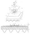
- FIG. 1is an exploded view of a roofing system with a roof attachment assembly according to an embodiment of the present invention.
- FIG. 1Ais an exploded view of an alternative embodiment of the roof attachment assembly according of FIG. 1 .
- FIG. 2is a cross-sectional view of the roofing system and the roof attachment assembly of FIG. 1 and FIG. 2 a is a cross-sectional view of a roofing system and a roof attachment assembly according to another embodiment of the present invention.
- FIG. 3is an exploded view of an alternative embodiment of a roof attachment assembly according to an embodiment of the present invention.
- FIGS. 4 and 5illustrate compression plates useable with the roofing system and the roof attachment assembly of FIGS. 1-3 .
- FIG. 6is an exploded view of a roofing system with a roof attachment assembly according to another embodiment of the present invention.
- FIG. 7is an exploded view of an alternative embodiment of the roofing system with the roof attachment assembly of FIG. 6 .
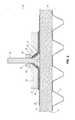
- FIG. 8is a cross-sectional view of the roofing system and the roof attachment assembly of FIG. 7 .
- FIG. 9is an exploded view of a roofing system with a roof attachment assembly according to another embodiment of the present invention.
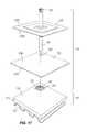
- FIG. 10is an assembled view of the roofing system with the roof attachment assembly of FIG. 9 .
- FIG. 11is a cross-sectional view of the roofing system and the roof attachment assembly of FIG. 9 .
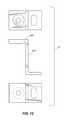
- FIGS. 12-14illustrate various brackets useable with the roofing system and the roof attachment assembly.
- FIG. 15illustrates an extension useable with the roofing system and the roof attachment assembly.
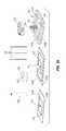
- FIGS. 16-18illustrate an alternative embodiment of a roofing system and a roof attachment assembly according to an embodiment of the present invention.
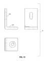
- FIGS. 19 and 20illustrates a further alternative embodiment of a roofing system and a roof attachment assembly according to an embodiment of the present invention.
- FIG. 21illustrates a plate useable with the roofing system and the roof attachment assembly of FIGS. 16-20 .
- FIG. 22illustrates a spacer useable with the roofing system and the roof attachment assembly of FIGS. 16-20 .
- phraseology and terminology used herein with reference to device or element orientationare only used to simplify description of embodiments of the present invention and do not alone indicate or imply that the device or element referred to must have a particular orientation.
- terms such as “first” and “second”are used herein for purposes of description and are not intended to indicate or imply relative importance or significance.
- FIGS. 1 and 2illustrate a roofing system 10 including a metal roof deck 12 , a roof substrate 14 (e.g., insulation, tarpaper, plywood or other decking material, and the like) supported on the roof deck 12 , a membrane 16 extending across and supported on the substrate 14 (i.e., placed immediately adjacent an upper surface of the substrate 14 or supported on one or more intermediate layers of roofing or sealing material, which in turn are placed on the substrate 14 ).
- the roofing system 10can be utilized on any of a variety of roof types, such as slate roofs, membrane roofs, aluminum roofs, standing seam roofs, tile roofs, shingle roofs, and the like.
- the roofing system 10is operable to support any of a variety of roof-mounted fixtures, such as, for example, snow fences, solar panels, conduit for solar panels, cables for lighting rods, an antenna, signs, billboards, or any of a number of other roof-mountable assemblies.
- roof-mounted fixturessuch as, for example, snow fences, solar panels, conduit for solar panels, cables for lighting rods, an antenna, signs, billboards, or any of a number of other roof-mountable assemblies.
- the roofing system 10can include any of a variety of flashing, seal and bracket arrangements, as will be discussed below.
- a roof attachment assembly 18can be coupled to the roofing system 10 with few or no fasteners extending through the membrane 16 .
- One such roof attachment assembly 18is illustrated in FIGS. 1 and 2 and includes a first membrane pad 20 , a plate 22 having a substantially frustoconical protrusion 24 , a second membrane pad 26 , a compression plate 28 , a washer 30 , a nut 32 and a bolt 34 .
- the bolt 34extends through the first membrane pad 20 , the frustoconical protrusion 24 of the plate 22 , the second membrane pad 26 , the compression plate 28 , the washer 30 and the nut 32 .
- the washer 30 and the nut 32can be omitted and the bolt 34 can be connected to a bracket 43 that is operable to act as a standoff and to support one or more roof mounted fixtures.
- the body of the bolt 34can substantially mate with a recess defined by the bracket to secure the bracket to the roof attachment assembly 18 .
- roof attachment assembly 18is substantially circular, other shapes are possible.
- the roof attachment assembly 18can be square, ovular, round, rectangular, triangular, pentagonal or other regular or non-regular shape.
- the plate 22can include one or more stiffening ribs or flanges to increase rigidity.
- the plate 22has a top surface 22 A facing the second membrane pad 26 and a bottom surface 22 B facing the first membrane pad 20 .
- the bottom surface 22 B of the platefaces the roof substrate and the top surface 22 A is spaced from the roof substrate.
- the top surface 22 A and/or the bottom surface 22 Bis coated with a material similar to the roof material, such as a membranous material. Embodiments in which both the top surface 22 A and the bottom surface 22 B are coated can omit one or more of the first membrane pad 20 and the second membrane pad 26 .
- the illustrated plate 22is substantially circular, but the plate can be other regular or non-regular shapes.
- the illustrated plate 22is metallic, but is other embodiments the plate is polymeric.
- the plate 22extends substantially along a plane.
- the frustoconical protrusion 24 of the plate 22extends away from the roof substrate 14 and defines an aperture 25 extending along an axis 27 .
- the aperture 25is circular, but in other embodiments, can have other regular or irregular shapes.
- the illustrated aperture 25is substantially centered on the upwardly extending protrusion 24 , but other, non-centered embodiments are possible.
- the frustoconical protrusion 24has a diameter in the plane, and the aperture 25 has diameter in a second plane that is substantially parallel to but spaced from the plane.
- the diameter of the aperture 25is less than the diameter of the protrusion 24 , to form a truncated cone or frustoconical shape.
- the protrusion 24can have other shapes and configurations, corresponding to the shape of an underside of an associated bracket 43 (shown in FIG. 1A ).
- the protrusion 24defines a concave interior side 37 and an exterior side 38 .
- frustoconicalincludes cones with rounded, flat, non-flat or nearly flat upper portions and truncated cones with rounded, flat, non-flat or nearly flat upper portions.
- the illustrated upwardly extending protrusion 24is circular, but in other embodiments, can be square, D-shaped, triangular, pentagonal, hexagonal, ovular, or other regular or irregular shapes.
- the concave interior side 37 of the protrusion 24may have a number of different shapes and configurations, including but not limited to configurations in which the arch provided by the interior side 37 does not include a uniform radius.
- the plate 22 and the bolt 34are connected to inhibit rotation of the bolt with respect to the plate 22 .
- the plate 22 and the bolt 34can be connected by spot welding, heat welding, forging, indenting the threads with pins or other projections, double-sided tape or other adhesive, or other permanent or semi-permanent connection.
- the connected plate 22 and bolt 34can be sold as a single component. In other embodiments, the plate 22 and the bolt 34 can be sold as separate components.
- the first membrane 20 and the second membrane 26have substantially circular shapes, but other shapes of these membranes are possible.
- the first membrane 20 , the second membrane 26 , and the roof membrane 16are constructed from the same material (e.g., polymeric material). In other embodiments, these membranes can be constructed from different materials.
- the diameter of the second membrane 26is larger than the diameter of the first membrane 20 , but in other embodiments the membranes 20 and 26 can have different diameters.
- the second membrane 26extends outwardly beyond the outer perimeter of the plates 22 and 28 .
- the second membrane 26is secured to the plate 22 and forms a skirt at least partially enclosing the plate 22 .
- the first membrane 20is positioned adjacent to the bottom surface 22 B of the plate 22
- the second membrane 26is positioned adjacent to the top surface 22 A of the plate 22
- the first membrane 20 and the second membrane 26include corresponding apertures 29 A and 29 B.
- the apertures 29 A and 29 B of the membranes 20 and 26are substantially aligned with the aperture 25 of the plate 22 , such that that the apertures 29 A and 29 B extend along the axis 27 .
- the compression plate 28can include a substantially frustoconical recess 36 that matingly receives the frustoconical protrusion 24 at least partially therein.
- the second membrane 26is compressed between the compression plate 28 and the plate 22 at an approximate center or aperture 29 A.
- the compression plate 28 and the plate 22act like a clamp on the second membrane 26 .
- the clamp created by the compression plate 28 and the plate 22deforms the second membrane 26 to define a circuitous path between the plates 22 and 28 .
- the bolt 34applies an adjustable compression force to the second membrane 26 between the compression plate 28 and the plate 22 .
- the outwardly extending base of the bolt 34is countered to matingly engage a recess defined in concave interior side 37 of the frustoconical protrusion 24 .
- the base of the bolt 34is positioned adjacent to the roof membrane 16 and the body of the bolt 34 is received within the frustoconical recess 36 of the plate 28 .
- the compression plate 28 illustrated in FIGS. 1-4 .is circular, but a square compression plate 29 having a frustoconical recess 36 is illustrated in FIG. 5 . Any suitable size and shape compression plate can be utilized. In some embodiments, the compression plate 28 , 29 can be omitted.
- the frustoconical protrusion 24 of the plate 22can substantially match a head shape of the bolt 34 .
- the plate 22 and the bolt 34are formed as a single unitary piece.
- the first membrane pad 20is connected to the bolt 34 (for example by heat welding). In such embodiments, the first membrane pad 20 is connected to the bolt 34 either prior to or while connecting the roof attachment assembly 18 to the roofing system 10 .
- the illustrated plate 22is substantially circular, but other can be other regular or non-regular shapes.
- washers and nuts, or other fastening apparatuses and methodsare utilized in place of washer 30 and nut 32 .
- projections or fasteners, other than bolt 34are utilized. These projections and fasteners may or may not be threaded.
- the nut 32can be omitted in embodiments that utilize a bracket having a threaded aperture. In such embodiments, pins or other protrusions can be used to fix the bracket to the fastener or projection.
- the roof attachment assembly 18can act as a seal positioned between the bracket and the roof to prevent leakage around the bracket through the roof.
- the roof attachment assembly 18in place of the washer 30 and the nut 32 , includes a single piece bracket 43 .
- the bracket 43replaces the plate 22 and the bolt 34 .
- the bracket 43includes at least one horizontal component 43 A and an upwardly-facing projection 43 B, such as any of the brackets illustrated in FIGS. 12-14 .
- any of the brackets illustrated in published application US 2010/0307074, the entire contents of which are herein incorporated by reference,can be utilized with the present invention.
- the fastenercan be inverted, such that the fastener does not penetrate the roof, but rather extends upward through the bracket.
- the bracketsare coupled to the roof by any non-penetrating fastening method, such as welding, adhering, gluing, bonding, and the like.
- the bracketscan include one or more stiffening ribs or flanges to increase rigidity. Further, the brackets can each include a coating on either or both of a top surface and a bottom surface of the bracket.
- the bracket 43is configured to be coupled to the compression plate 28 or to the second membrane 26 and is operable to support one or more roof mounted fixtures.
- the bracket 43 illustrated in FIG. 1Ais substantially rectangular, but a square, a circle, or other shaped and sized bracket can be utilized.
- the bracket 43includes a first recess 44 , a second recess 45 and an aperture 46 extending between the first recess 44 and the second recess 45 .
- the illustrated first recess 44 of the bracket 43is substantially frustoconical and, when the assembly omits the second plate 28 , the recess 44 condmatingly receives the frustoconical protrusion 24 at least partially therein.
- the frustoconical protrusion 24can substantially match the shape of the first recess 44 .
- the bolt 34can extend into the first recess 44 and engage the bracket 43 .
- the second recess 45 of the bracket 43is sized to engage the head of a second bolt 34 A to inhibit rotation of the second bolt 34 A within the second recess 45 .
- the bracket aperture 46is substantially circular, but other shapes, such as ovular, square, rectangular, hexagonal, and the like are possible. In one embodiment, the bracket aperture 46 is sized to receive the bolt 34 or any fastener, protrusion, or the like therethrough. The circular shape of the aperture 46 permits flexibility and slight relative movement between the bracket 43 and the bolt 34 , fastener, projection or the like, when installed. The bracket aperture 46 is substantially aligned with the plate aperture 25 and the apertures 29 A and 29 B of the membranes 20 and 26 , such that that the bracket apertures 32 also extends along the axis 27 .
- At least one extensionsuch as the extension 42 shown in FIG. 15
- the extension 42is substantially rectangular, but in other embodiments, the extension 42 can have different shapes.
- the extension 42includes a top recess 42 A and a bottom recess 42 B. In some embodiments, the bottom recess 42 B is constructed to accept the frustoconical protrusion 24 .
- the extensions 42can be threaded onto the bolt 34 (e.g., through the bottom recess 42 B) or connected to another fastener in placed of the nut 32 .
- the extension 42provides adjustability and flexibility to various design and roof arrangements.
- Other suitable height-adjustment arrangementssuch as the bracket illustrated in FIGS. 12-14 , or any of the height-adjustable brackets in co-pending patent application Ser. No. 12/727,726, filed Oct. 28, 2010, the entire contents of which are herein incorporated by reference, can be utilized in combination with the present invention.
- the roof attachment assembly 18can be coupled to the roofing system 10 with any suitable non-penetrating fastening method, such as welding, adhering, gluing, bonding, and the like.
- the roof attachment assembly 18can be coupled directly to the roof membrane 16 (as shown in FIGS. 1 and 2 ) or can be coupled to a target patch T positioned on the roof membrane 16 of the roof substrate 14 (as shown in FIG. 3 ).
- the roof attachment assembly 18can be coupled to the roofing system above the target patch T (also known as a membrane or a flashing) and a plate P that is secured by a roof-penetrating fastener F.
- the plate Pis substantially circular, but the plate P can be other regular or non-regular shapes.
- the plate Pdefines a counterbore or recess 40 that is configured to accept the fastener F.
- the plate Pdefines a top surface 41 spaced from the roof membrane 16 and the roof substrate 14 .
- One of the sides of the target patch Tis adjacent to the top surface 41 of the plate P, and the other side of the target patch T is adjacent to the first membrane 20 .
- the illustrated embodimentincludes a RhinoBond® plate P and fastener F, but other plates, fasteners and other roof mounting structures can be utilized.
- the diameter of the target patch Tis substantially larger than the diameter of the plate P.
- the target patch T and the plate Pcan have different diameters.
- the fastener Fcan be a bolt, a screw, or any other suitable fastener that allows that plate P to be securely coupled to the roof substrate 14 .
- the target patch Tseals any penetrations caused by the fastener F.
- the roof attachment assembly 18is operable to support any of a variety of roof-mounted fixtures, such as snow guards, snow fences, solar panels, conduit for solar panels, cables for lighting rods, an antenna, signs, billboards, or any other assembly mountable to a roof.
- roof-mounted fixturessuch as snow guards, snow fences, solar panels, conduit for solar panels, cables for lighting rods, an antenna, signs, billboards, or any other assembly mountable to a roof.
- the second membrane pad 26is welded, glued or otherwise adhered to the membrane 16 only around a perimeter of the first membrane pad 20 .
- a secured bondis formed between the second membrane pad 26 and the roof membrane 16 .
- this bondnon-removably secures the roof attachment assembly 18 to the roof. It is to be understood that non-removable attachment requires damage to the roof membrane 16 in order to remove the roof attachment assembly 18 from the roof 10 .
- the plate 22is coated on the top surface 22 A and/or the bottom surface 22 B with a membranous material, an adhesive.
- an adhesivesuch as double-sided tape or a double-sided RhinoBond® plate is connected to the bottom surface 22 B, to adhere the plate 22 directly to the membrane 16 .
- the first membrane pad 20is coupled to the roof membrane 16 by any suitable non-penetrating method, and then in a subsequent step, the plate 22 or one of the brackets is coupled to the first membrane pad 20 .
- the plate 22 or one of the bracketsis coupled to the first membrane pad 20 to form a single unit, and the single unit is coupled to the roof membrane 16 by any suitable non-penetrating method.
- the second membrane pad 26can be omitted.
- the plate 22 or one of the bracketsis coupled to the roof membrane 16 by any suitable non-penetrating method, and then the second membrane pad 26 is coupled to the plate 22 or one of the brackets.
- the plate 22 or one of the bracketsis coupled to the second membrane pad 26 to form a single unit, and the single unit is coupled to the roof membrane 16 by any suitable non-penetrating method.
- the first membrane pad 20can be omitted.
- the first membrane pad 20is coupled to the roof membrane 16 by any suitable non-penetrating method
- the plate 22 or one of the bracketsis coupled to the first membrane pad 20
- the second membrane pad 26is coupled to the plate 22 or one of the brackets, is coupled to the first membrane pad 20 , and is coupled to the roof membrane 16 .
- the plate 22 or one of the bracketsis coupled to the first membrane pad 20 and the second membrane pad 26 to form a single unit, and the single unit is coupled to the roof membrane 16 by any suitable non-penetrating method.
- One suitable non-penetrating fastening methodincludes providing an adhesive on any of the roof membrane 16 , the first membrane 20 , the plate 22 and the second membrane 26 .
- one or more of the membranes 16 , 20 , 26comprises a meltable material that can be construed as an adhesive.
- a separate adhesiveis applied to the top 22 A and/or the bottom 22 B of the plate 22 .
- the roof attachment assembly 18is positioned on the roof membrane 16 , and is then heated by a heat source, such as by an induction coil. The adhesive at least partially melts in response to the heat source. Once solidified, the adhesive can couple the roof attachment assembly 18 to the roof membrane 16 .
- one or more weightsare positioned on the roof attachment assembly 18 during or subsequent to heating, to deform the molten adhesive, and thereby encourage adhesion of the roof attachment assembly 18 to the roof membrane 16 .
- Other suitable methodsare possible, such as welding, gluing, adhering, bonding and the like, and the present method is given by way of example only.
- the first membrane 20is adhered to the roof membrane 16 to couple the roof attachment assembly 18 to the roofing system 10 .
- the second membrane 26is adhered to the roof membrane 16 to couple the roof attachment assembly 18 to the roofing system 10 .
- the plate 22is adhered to the roof membrane 16 to couple the roof attachment assembly 18 to the roofing system 10 .
- the second membrane 26is adhered to the plate 22 , and the plate 22 is adhered to the roof membrane 16 to couple the roof attachment assembly 18 to the roofing system 10 .
- the second membrane 26is adhered to the plate 22 , the plate 22 is adhered to the first membrane 20 and the first membrane 20 is adhered to the roof membrane 16 to couple the roof attachment assembly 18 to the roofing system 10 .
- two or more of the first membrane 20 , the plate 22 and the second membrane 26are adhered to the roof membrane 16 to couple the roof attachment assembly 18 to the roofing system 10 .
- FIGS. 6-8illustrate another construction of a roof attachment assembly 50 .
- the roof attachment assembly 50can be coupled to a roofing system 10 , which is similar to the previously described roofing system 10 of FIGS. 1-3 .
- the roof attachment assembly 50can be attached to a roof substrate 14 having a roof membrane 16 .
- the roof attachment assembly 50includes a first membrane pad 52 supported on the roof substrate 14 , a plate or a base member 54 having a substantially frustoconical protrusion 56 , a second membrane pad 58 , a bracket 60 , and a fastener 62 (e.g., a bolt).
- a fastener 62e.g., a bolt
- the fastener 62extends through the plate 54 , the second membrane 58 , and the bracket 60 to couple the plate 54 , the second membrane 58 and the bracket 60 .
- the fastener 62can also extend through the roof substrate 14 .
- the first membrane 52is supported on the roof substrate 14 .
- the first membrane 52defines a perimeter that is larger than the perimeter defined by the plate 54 and the second membrane 58 .
- the first membrane 52 and the roof substrate 14can be connected by spot welding, heat welding, forging, indenting the threads with pins or other projections, double-sided tape or other adhesive, by fasteners, or other permanent or semi-permanent connection.
- the length of the first membraneis approximately sixteen inches, but the length can be larger or smaller.
- the illustrated plate 54 of the roof attachment assembly 50is substantially circular, but the plate can be other regular or non-regular shapes.
- the 54is metallic, but is other embodiments the plate is polymeric.
- the plate 54defines a first surface 54 A positioned substantially adjacent the first membrane 52 , and a second surface 54 B spaced from the roof substrate and the first membrane.
- the frustoconical protrusion 56 of the plate 54extends away from the roof substrate 14 along an axis 64 . Further, the first surface 54 A of the plate 54 forms a frustoconical recess 65 and the second surface 54 B forms the frustoconical protrusion 56 .
- the frustoconical protrusion 56 of the plate 54defines an aperture 66 extending along the axis 64 from the first surface 54 A to the second surface 54 B.
- the first aperture 66is substantially centrally positioned in the frustoconical protrusion 56 .
- the plate 54includes a plurality of openings 67 extending from the first surface 54 A through the second surface 54 B.
- the openings 67are configured to accept fasteners 68 (e.g., bolts, screws, etc.) that couple the plate 54 to the first membrane 52 and to the roof substrate 14 of the roofing system 10 .
- the plate 54does not use fasteners 68 , but is coupled to the roof substrate 14 via other suitable non-penetrating methods or mechanisms (e.g., via adhesive, heat welding, forging, etc.).
- the second membrane 58is positioned substantially adjacent the second surface 54 B of the plate 54 and is coupled to the first membrane 52 .
- the second membrane 58defines a surface area or a perimeter that is greater than the surface area of the plate 54 .
- the second membrane 58is deformable to substantially conform to the frustoconical protrusion 56 of the plate 54 when the second membrane 58 attaches to the plate 54 .
- the second membrane 58defines an aperture 70 extending through the second membrane 58 , where the aperture 70 is substantially aligned with the aperture 66 of the plate 54 , such that the aperture 70 extends along the axis 64 .
- the bracket 60 of the roof attachment assembly 50is coupled to the second membrane 58 via the fastener 62 .
- the bracket 60is operable to support at least one roof-mounted assembly.
- the bracket 60defines a first surface 60 A spaced from the second membrane 58 and a second surface 60 B positioned substantially adjacent the second membrane 58 .
- the bracket 60further defines an aperture 72 extending from the first surface 60 A to the second surface 60 B.
- the frustoconical protrusion 56extends at least partially into the bracket aperture 72 . Because the second membrane 58 is deformed by the frustoconical protrusion 56 , the second membrane 58 also extends into the bracket aperture 72 .
- the bracket aperture 72is substantially aligned with the aperture 66 of the plate 54 and the aperture 70 of the second membrane 58 such the bracket aperture 72 extends along the axis 64 .
- the fastener 62 of the roof attachment assembly 50is oriented along the axis 64 and extends through the aperture 66 of the plate 54 , the aperture 70 of the second membrane 58 , and the bracket aperture 72 to couple the plate 54 to the second membrane 58 and to the bracket 60 .
- the diameter defined by the plate 54is greater than the diameter defined by the aperture 66 of the plate 54 and the diameter defined by the aperture 70 of the second membrane 58 .
- the roof attachment assembly 50is constructed without the bracket 60 or the first membrane 52 (see FIG. 6 ).
- the plate 54is directly positioned on the roof substrate 14 or the roof membrane 16 of the roofing system 10 .
- the plate 54can be heat welded, or otherwise coupled, to the second membrane 58 .
- the plate 54can be attached to the roof substrate 14 via the fasteners 68 or by any other reasonable means.
- the fastener 62extends through the aperture 66 of the plate 54 and the aperture 70 of the second membrane 58 to couple the plate to the second membrane 58 .
- the fastener 62 of the roof attachment assembly 50is configured to accept a compression fitting 69 (see FIG. 8 ).
- the fastener 62further defines an attachment point 76 exposed for mechanical fastening.
- FIGS. 9-11illustrate another construction of a roof attachment assembly 80 .
- the roof attachment assembly 80can be attached to a roofing system 10 , which is similar to the previously described roofing system 10 .
- the roof attachment assembly 80includes a first membrane pad 82 supported on the roof substrate 14 or the roof membrane 16 , a plate 84 defining a center aperture 85 , a second membrane pad 86 , a bracket 88 , and a fastener 90 (e.g., a bolt).
- the fastener 90extends upwardly through a recess of the bracket 88 and is operable to support one or more roof mounted fixtures.
- the roof attachment assembly 80can be coupled to the roofing system 10 with any suitable non-penetrating fastening method, such as welding, adhering, gluing, bonding, and the like.
- the roof attachment assembly 80can be coupled directly to the roof membrane 16 or can be coupled to a plate 92 positioned on the roof membrane 16 of the roof substrate 14 . As illustrated in FIGS. 9-11 , the plate 92 is secured by a roof-penetrating fastener F.
- the roof attachment assembly 80is operable to support any of a variety of roof-mounted fixtures, such as snow guards, snow fences, solar panels, conduit for solar panels, cables for lighting rods, an antenna, signs, billboards, or any other assembly mountable to a roof.
- the plate 84has a top surface 84 A facing the second membrane pad 86 and a bottom surface 84 B facing the first membrane pad 82 and the membrane roof.
- the top surface 84 A and/or the bottom surface 84 Bis coated with a material similar to the roof material, such as a membranous material.
- a fastener(not shown) can extend through the aperture 85 of the plate 84 to couple the plate 84 and the first membrane 82 to the roof.
- the roof attachment assembly 80may omit the second membrane 86 and/or the bracket 88 .
- the fastener extending through the plate 84 and the first membrane 82can be configured to attach to a bracket that supports a roof mounting fixture. Further, in these embodiments, the plate 84 and the first membrane 82 can be single monolithic component.
- the illustrated plate 84is substantially circular, but the plate can be other regular or non-regular shapes.
- the illustrated plate 84is metallic, but is other embodiments the plate is polymeric.
- the aperture 85 defined by the plate 84is circular, but in other embodiments, can have other regular or irregular shapes.
- the illustrated aperture 85is positioned substantially centered on the plate 84 , but other, non-centered embodiments are possible.
- the first membrane 82 and the second membrane 86have substantially circular shapes, but other shapes of these membranes are possible.
- the first membrane 82 and the second membrane 86are constructed from the same material (e.g., polymeric material).
- the diameter of the second membrane 86is smaller than the diameter of the first membrane 82 , but in other embodiments the membranes 82 and 86 can have different diameters.
- the second membrane 86extends outwardly beyond the outer perimeter of the plate 84 and shrouds the plate 84 .
- the second membrane 86is configured to substantially conform to the shape of the plate 84 , when the plate 84 is compressed between the first membrane 82 and the second membrane 86 .
- the first membrane 82is positioned adjacent to the bottom surface 84 B of the plate 84
- the second membrane 86is positioned adjacent to the top surface 84 A of the plate 84
- the first membrane 82 and the second membrane 86include corresponding apertures 82 A (not shown) and 86 B.
- the apertures 82 A and 86 B of the membranes 82 and 86are substantially aligned with the aperture 85 of the plate 84 .
- the first membranedoes not include an aperture.
- the bracket 88is configured to be coupled to the second membrane 86 and is operable to support one or more roof mounted fixtures.
- the bracket 88 illustrated in FIGS. 9-11is substantially circular, but a square, a rectangular, or other shaped and sized bracket can be utilized.
- the bracketdefines a first recess 91 positioned on the upper portion of the bracket 88 , and a second recess or an aperture 94 positioned near the second membrane 86 .
- the bracket aperture 94is substantially circular, but other shapes, such as ovular, square, rectangular, hexagonal, and the like are possible.
- the assembly 80can include a fastener (not shown) extending through the apertures 82 A, 85 , and 86 B and engaging the second recess 94 of the bracket 88 .
- the circular shape of the aperture 94permits flexibility and slight relative movement between the bracket 88 and the fastener, projection or the like, when installed.
- the first recess 91 of the bracket 88is sized to engage the head of the fastener 90 to inhibit rotation of the fastener 90 within the first recess 91 .
- the roof attachment assembly 80can include other types of plates that differ from the plate 84 . Further, the roof attachment assembly 80 can include any of the previously described brackets.
- a possible non-penetrating fastening method for attaching the roof attachment assembly 80includes providing an adhesive on any of the roof membrane 16 , the plate 84 , the first membrane 82 and the second membrane 86 .
- one or more of the roof membrane 16 , the plate 84 , the first membrane 82 and the second membrane 86comprises a meltable material that can be construed as an adhesive.
- a separate adhesiveis applied to the top and/or the bottom 84 A/ 84 B of the plate 84 .
- the roof attachment assembly 80is positioned on the roof membrane 16 , and is then heated by a heat source, such as by an induction coil. The adhesive at least partially melts in response to the heat source. Once solidified, the adhesive can couple the roof attachment assembly 80 to the roof membrane 16 .
- Other suitable attachment methodsare possible, such as welding, gluing, adhering, bonding and the like, and the present method is given by way of example only.
- the first membrane 82is adhered to the roof membrane 16 to couple the roof attachment assembly 80 to the roof 10 .
- the first membrane 82 and the second membrane 86are adhered to the plate 84 and these elements are adhered to the plate 92 and to the roof membrane 16 to couple the roof attachment assembly 80 to the roof 10 .
- the bracket 88is adhered to the second membrane 86 , the first membrane 82 is adhered to the plate 84 , and the first membrane 82 is adhered to the plate 92 and to the roof membrane 16 to couple the roof attachment assembly 80 to the roof 10 .
- both the plate 92 and the first membrane 82are adhered to the roof membrane 16 to couple the roof attachment assembly 80 to the roof 10 .
- the plate 92may not include fasteners.
- FIGS. 16-22illustrate another construction of a roofing system 110 including a metal roof deck 112 , a roof substrate 114 (e.g., insulation, tarpaper, plywood or other decking material, and the like) supported on the roof deck 112 , a membrane 116 extending across the substrate 114 (i.e., placed immediately adjacent an upper surface of the substrate 114 or supported on one or more intermediate layers of roofing or sealing material, which in turn are placed on the substrate 114 ).
- the roofing system 110can be utilized on any of a variety of roof types, such as slate roofs, membrane roofs, aluminum roofs, standing seam roofs, tile roofs, shingle roofs, and the like.
- the roofing system 110possesses all characteristics of the previously described roofing systems 10 .
- the roofing system 110is operable to support any of a variety of roof-mounted fixtures, such as, for example, snow fences, solar panels, conduit for solar panels, cables for lighting rods, an antenna, signs, billboards, or any of a number of other roof-mountable assemblies.
- roof-mounted fixturessuch as, for example, snow fences, solar panels, conduit for solar panels, cables for lighting rods, an antenna, signs, billboards, or any of a number of other roof-mountable assemblies.
- the roofing system 110can include any of a variety of flashing, seal and plate arrangements, as will be discussed below.
- a roof attachment assembly 118can be coupled to the roofing system 110 with few or no fasteners extending through the membrane 116 .
- One such roof attachment assembly 118is illustrated in FIGS. 12-14 .
- the illustrated roof attachment assembly 118includes a plate (also called a base member) 120 having an upwardly extending fastener 122 , a membrane pad 124 , a compression washer 126 having a substantially frustoconical aperture or a pocket 128 , a spacer 130 , a flashing 132 and a hose clamp 134 .
- the roof attachment assembly 118can be coupled to the roofing system 110 with any suitable non-penetrating fastening method, such as welding, adhering, gluing, bonding, and the like.
- the roof attachment assembly 118is operable to support any of a variety of roof-mounted fixtures, such as described above for the roof attachment assembly 18 .
- the illustrated roof attachment assembly 118is substantially square, other shapes are possible.
- the roof attachment assembly 118can be round, ovular, rectangular, triangular, pentagonal or other regular or non-regular shape.
- FIGS. 16-18illustrate an embodiment of the roof attachment assembly 118 in which the plate 120 is connected to the roofing system 110 by a non-penetrating fastening method.
- FIGS. 19 and 20illustrate an embodiment of the roof attachment assembly 118 in which the plate 120 is connected to the roofing system 110 by fasteners 135 that penetrate the roofing system 110 .
- the membrane 124acts as a target patch over the fasteners 135 .
- the roof attachment assembly 118is considered to not penetrate the roofing system 110 , because the membrane pad 124 (or target patch) is connected to the roofing system 110 by welding, adhesive or by some other non-penetrating manor to suitably inhibit or prevent any leakage through the penetrations caused by the fasteners 135 .
- FIG. 21illustrates the plate 120 and the fastener 122 in a greater detail.
- the plate 120 of the roof attachment assembly 118can include a substantially frustoconical protrusion 136 defining an aperture 137 .
- the plate 120can include one or more stiffening ribs or flanges to increase rigidity.
- Other type of platescan be utilized in place of plate 120 and the roof attachment assembly 118 can include more than one plate 120 .
- the plate 120has a top surface 120 A facing the membrane pad 124 and a bottom surface 120 B facing the roof membrane 116 .
- the top surface 120 A and/or the bottom surface 120 Bis coated with a material similar to the roof material, such as a membranous material.
- Embodiments in which both the top surface 120 A and the bottom surface 120 B are coatedcan omit the membrane pad 124 .
- the plate 120is coupled to the roof by any non-penetrating fastening method, such as welding, adhering, gluing, bonding, and the like.
- the plate 120can be coupled to the roof by using fasteners 135 .
- the plate 120includes a plurality of openings 147 extending from the top surface 120 A through the bottom surface 120 B.
- the openings 147are configured to accept the fasteners 135 (e.g., bolts, screws, etc.) that couple the plate 120 to the roof substrate 114 of the roofing system 110 .
- the plate 120does not use fasteners 135 , but is coupled to the roof substrate 116 via other suitable non-penetrating methods or mechanisms (e.g., via adhesive, heat welding, forging, etc.).
- the fastener 122extends through the frustoconical protrusion 136 and the aperture 137 of the plate 120 .
- the frustoconical protrusion 136extends at least partially into the frustoconical aperture 128 of the washer 126 .
- the washer 126can be circular, square, ovular, pentagonal or any other suitable size and shape. In some embodiments, the washer 126 can be omitted.
- the plate 120 and the upwardly extending fastener 122are formed as a single unitary piece. In some embodiments, the plate 120 and the upwardly extending fastener 122 are formed as separate pieces and joined during installation.
- any of the plates discussed herein and described abovecan be utilized in place of the plate 120 .
- the platesare coupled to the roof by any non-penetrating fastening method, such as welding, adhering, gluing, bonding, and the like.
- the platescan each include a coating on either or both of a top surface and a bottom surface of the plate.
- the plate 120is coupled to the roof membrane 116 by any suitable non-penetrating method, and then the membrane pad 124 is coupled to the plate 120 .
- the plate 120is coupled to the membrane pad 124 to form a single unit, and the single unit is coupled to the roof membrane 116 by any suitable non-penetrating method.
- the membrane 124has a substantially rectangular form, but other shapes of the membrane 124 are also possible.
- the membrane 124is positioned adjacent to the top surface 120 A of the plate 120 , and defines an aperture 125 that substantially aligns with the aperture 137 of the plate 120 and the frustoconical aperture 128 of the washer 126 .
- the membrane 124defines a top surface 124 A and a bottom surface 124 B. In other embodiments, the membrane 124 may be constructed without the aperture 125 .
- the flashing 132is positioned adjacent to the top surface 124 A of the membrane 124 .
- the illustrated flashing 132comprises metal, but in other embodiments, other material(s) can also be used to construct the flashing 132 .
- the flashing 132can include a coating on top surface 132 A and/or a bottom surface 132 B. In embodiments that include a coating on the bottom surface 132 B, the coating can be adhered or otherwise coupled to the membrane 116 , and the membrane 124 can be omitted. In embodiments that omit the membrane pad 124 , the flashing 132 is directly connected to the membrane 116 . In some such embodiments, the flashing 132 can include an adhesive, such as double-sided tape, on the bottom surface 132 B.
- the flashing 132defines a projection area 133 that is configured to accept at least a portion of the frustoconical protrusion 136 and the washer 126 .
- the flashing 132further defines a flashing aperture 138 that substantially aligns with the aperture 125 of the membrane 124 , the aperture 137 of the plate 120 , and the frustoconical aperture 128 of the washer 126 .
- the flashing aperture 138has a diameter that is larger than the diameter of apertures 125 , 137 , and 125 , such that it allows the spacer 130 to pass through the aperture 138 .
- the perimeters of the membrane 124 and the pipe flashing 132are substantially equal, and both perimeters are larger than the perimeter of the plate 120 . In other embodiment, these elements of the roof attachment assembly 118 can have different perimeters.
- the fastener 122extends through the aperture 137 of the frustoconical protrusion 136 , the frustoconical aperture 128 of the washer 126 , and engages the spacer 130 .
- the spacer 130includes a top aperture 130 A and a bottom aperture 130 B that are configured to accept a fastener (e.g., fastener 122 ).
- the spacer 130extends through the aperture 138 of the flashing 132 .
- other fastening apparatuses and methods, or combinations of fastening apparatusesare utilized in place of washer 126 , spacer 130 , flashing 132 and hose clamp 134 .
- One suitable non-penetrating fastening methodincludes providing an adhesive on any of the roof membrane 116 , the plate 120 , the membrane 124 and the flashing 132 .
- one or more of the roof membrane 116 , the plate 120 , the membrane 124 and the flashing 132comprises a meltable material that can be construed as an adhesive.
- a separate adhesiveis applied to the top 120 A and/or the bottom 120 B of the plate 120 .
- the roof attachment assembly 118is positioned on the roof membrane 116 , and is then heated by a heat source, such as by an induction coil. The adhesive at least partially melts in response to the heat source. Once solidified, the adhesive can couple the roof attachment assembly 118 to the roof membrane 116 .
- Other suitable attachment methodsare possible, such as welding, gluing, adhering, bonding and the like, and the present method is given by way of example only.
- the membrane 124is adhered to the roof membrane 116 to couple the roof attachment assembly 118 to the roof 110 .
- the plate 120is adhered to the roof membrane 116 to couple the roof attachment assembly 118 to the roof 110 .
- the membrane 124is adhered to the plate 120 and the plate 120 is adhered to the roof membrane 116 to couple the roof attachment assembly 118 to the roof 110 .
- the membrane 124is adhered to the plate 120 , and the membrane 124 is adhered to the roof membrane 116 to couple the roof attachment assembly 118 to the roof 110 .
- both the plate 120 and the membrane 124are adhered to the roof membrane 116 to couple the roof attachment assembly 118 to the roof 110 .
Landscapes
- Engineering & Computer Science (AREA)
- Architecture (AREA)
- Civil Engineering (AREA)
- Structural Engineering (AREA)
- Physics & Mathematics (AREA)
- Mechanical Engineering (AREA)
- Sustainable Development (AREA)
- Life Sciences & Earth Sciences (AREA)
- Sustainable Energy (AREA)
- Thermal Sciences (AREA)
- Chemical & Material Sciences (AREA)
- Combustion & Propulsion (AREA)
- General Engineering & Computer Science (AREA)
- Theoretical Computer Science (AREA)
- General Physics & Mathematics (AREA)
- Roof Covering Using Slabs Or Stiff Sheets (AREA)
- Connection Of Plates (AREA)
Abstract
Description
Claims (20)
Priority Applications (13)
| Application Number | Priority Date | Filing Date | Title |
|---|---|---|---|
| US13/272,005US8826618B2 (en) | 2011-03-15 | 2011-10-12 | Roof mount assembly |
| PCT/US2012/027798WO2012125327A2 (en) | 2011-03-15 | 2012-03-06 | Roof mount assembly |
| US14/257,521US9134044B2 (en) | 2010-01-25 | 2014-04-21 | Roof mount assembly |
| US14/445,998US20140345213A1 (en) | 2011-03-15 | 2014-07-29 | Roof mount assembly |
| US14/823,505US9447988B2 (en) | 2010-01-25 | 2015-08-11 | Roof mount assembly |
| US15/248,942US10060133B2 (en) | 2010-01-25 | 2016-08-26 | Roof mount assembly |
| US15/384,293US10151114B2 (en) | 2010-01-25 | 2016-12-19 | Roof mount assembly |
| US16/000,797US10472828B2 (en) | 2010-01-25 | 2018-06-05 | Roof mounting system |
| US16/215,594US10676929B2 (en) | 2010-01-25 | 2018-12-10 | Roof mount assembly |
| US16/863,997US11118353B2 (en) | 2010-01-25 | 2020-04-30 | Roof mount assembly |
| US17/354,536US11692352B2 (en) | 2009-02-11 | 2021-06-22 | Roof mount assembly |
| US17/581,332US11851884B2 (en) | 2009-02-11 | 2022-01-21 | Roof mount assembly |
| US18/510,100US12442191B2 (en) | 2023-11-15 | Roof mount assembly |
Applications Claiming Priority (3)
| Application Number | Priority Date | Filing Date | Title |
|---|---|---|---|
| US201161452983P | 2011-03-15 | 2011-03-15 | |
| US201161485693P | 2011-05-13 | 2011-05-13 | |
| US13/272,005US8826618B2 (en) | 2011-03-15 | 2011-10-12 | Roof mount assembly |
Related Parent Applications (5)
| Application Number | Title | Priority Date | Filing Date |
|---|---|---|---|
| US13/271,650Continuation-In-PartUS8701354B2 (en) | 2009-02-11 | 2011-10-12 | Roofing grommet forming a seal between a roof-mounted structure and a roof |
| US13/623,348Continuation-In-PartUS8782983B2 (en) | 2009-02-11 | 2012-09-20 | Roof mount assembly and method of mounting same |
| US14/257,521ContinuationUS9134044B2 (en) | 2009-02-11 | 2014-04-21 | Roof mount assembly |
| US14/823,505ContinuationUS9447988B2 (en) | 2009-02-11 | 2015-08-11 | Roof mount assembly |
| US15/248,942Continuation-In-PartUS10060133B2 (en) | 2009-02-11 | 2016-08-26 | Roof mount assembly |
Related Child Applications (4)
| Application Number | Title | Priority Date | Filing Date |
|---|---|---|---|
| US12/727,726Continuation-In-PartUS8153700B2 (en) | 2009-02-11 | 2010-03-19 | Roofing system and method |
| US13/623,348Continuation-In-PartUS8782983B2 (en) | 2009-02-11 | 2012-09-20 | Roof mount assembly and method of mounting same |
| US14/257,521Continuation-In-PartUS9134044B2 (en) | 2009-02-11 | 2014-04-21 | Roof mount assembly |
| US14/445,998DivisionUS20140345213A1 (en) | 2011-03-15 | 2014-07-29 | Roof mount assembly |
Publications (2)
| Publication Number | Publication Date |
|---|---|
| US20120233958A1 US20120233958A1 (en) | 2012-09-20 |
| US8826618B2true US8826618B2 (en) | 2014-09-09 |
Family
ID=46827334
Family Applications (2)
| Application Number | Title | Priority Date | Filing Date |
|---|---|---|---|
| US13/272,005ActiveUS8826618B2 (en) | 2009-02-11 | 2011-10-12 | Roof mount assembly |
| US14/445,998AbandonedUS20140345213A1 (en) | 2011-03-15 | 2014-07-29 | Roof mount assembly |
Family Applications After (1)
| Application Number | Title | Priority Date | Filing Date |
|---|---|---|---|
| US14/445,998AbandonedUS20140345213A1 (en) | 2011-03-15 | 2014-07-29 | Roof mount assembly |
Country Status (2)
| Country | Link |
|---|---|
| US (2) | US8826618B2 (en) |
| WO (1) | WO2012125327A2 (en) |
Cited By (38)
| Publication number | Priority date | Publication date | Assignee | Title |
|---|---|---|---|---|
| US8938932B1 (en)* | 2013-12-13 | 2015-01-27 | Quality Product Llc | Rail-less roof mounting system |
| US20150326171A1 (en)* | 2008-05-08 | 2015-11-12 | Sustainable Technologies, Llc | Roof Mounted Installation Solar Power System |
| US20160040431A1 (en)* | 2011-10-17 | 2016-02-11 | Joel A. Stanley | System for Mounting Objects to Polymeric Membranes |
| US20160176105A1 (en)* | 2011-10-17 | 2016-06-23 | Bwdt, Llc | System for mounting objects to polymeric membranes |
| US20160226435A1 (en)* | 2015-01-30 | 2016-08-04 | Solarcity Corporation | Photovoltaic mounting system |
| US20170005611A1 (en)* | 2015-07-02 | 2017-01-05 | Mitch Atchley | Roof tile with integrated riser |
| USD793582S1 (en)* | 2013-10-01 | 2017-08-01 | Certainteed Corporation | Roofing panel |
| US20180062560A1 (en)* | 2016-08-23 | 2018-03-01 | Pegasus Solar Inc. | Solar mounting assemblies |
| US9985579B2 (en) | 2016-04-12 | 2018-05-29 | Preformed Line Products Co. | Mounting assembly for mounting a solar panel |
| US10077562B2 (en) | 2011-02-25 | 2018-09-18 | Dustin M. M. Haddock | Mounting device for building surfaces having elongated mounting slot |
| US10097133B2 (en) | 2016-04-14 | 2018-10-09 | Shahriar Shamloo Aliabadi | Racking system for installing solar panels |
| US10337764B2 (en) | 2016-04-14 | 2019-07-02 | Ironridge, Inc. | Conduit mount assembly |
| US10443896B2 (en) | 2016-07-29 | 2019-10-15 | Rmh Tech Llc | Trapezoidal rib mounting bracket with flexible legs |
| US10502457B2 (en) | 2010-03-03 | 2019-12-10 | Robert M. M. Haddock | Photovoltaic module mounting assembly |
| US10541641B2 (en) | 2017-10-30 | 2020-01-21 | Solar Slate Solutions | Solar panel mount systems and methods |
| US10601361B2 (en) | 2017-10-30 | 2020-03-24 | Solar Slate Solutions | Solar panel mount with compression spacer systems and methods |
| US10601360B2 (en) | 2017-09-08 | 2020-03-24 | Unirac Inc. | Replacement tile mount for mounting solar panels on tile roofs |
| US10634175B2 (en) | 2011-12-29 | 2020-04-28 | Rmh Tech Llc | Mounting device for nail strip panels |
| WO2020086734A1 (en) | 2018-10-23 | 2020-04-30 | Pv Solutions, Llc | Devices, methods, and systems for installation of photovoltaic systems |
| US10640980B2 (en) | 2016-10-31 | 2020-05-05 | Rmh Tech Llc | Metal panel electrical bonding clip |
| US10815667B2 (en)* | 2015-12-29 | 2020-10-27 | Araystays Corporation | Apparatus and methods for a noninvasive roof attachment system with vertical members |
| US10903785B2 (en) | 2018-03-21 | 2021-01-26 | Rmh Tech Llc | PV module mounting assembly with clamp/standoff arrangement |
| US10948002B2 (en) | 2018-12-14 | 2021-03-16 | Rmh Tech Llc | Mounting device for nail strip panels |
| US10954676B2 (en)* | 2019-03-20 | 2021-03-23 | Johns Manville | Magnetic roof attachment |
| US11041310B1 (en) | 2020-03-17 | 2021-06-22 | Rmh Tech Llc | Mounting device for controlling uplift of a metal roof |
| US11114974B2 (en)* | 2017-08-25 | 2021-09-07 | Sunrun South Llc | Surface mount assemblies for a solar panel system |
| FR3109167A1 (en)* | 2020-04-14 | 2021-10-15 | Systovi | A method of installing a device for fixing a photovoltaic panel on the roof and a fixing device for installing a panel on the roof. |
| US11255369B2 (en)* | 2015-07-29 | 2022-02-22 | Ironridge, Inc. | Bracket mount for securing solar panel rail guides on a roof |
| US11352793B2 (en) | 2020-03-16 | 2022-06-07 | Rmh Tech Llc | Mounting device for a metal roof |
| US11549639B2 (en) | 2018-09-25 | 2023-01-10 | Green Link Holdings, LLC | Magnetic roofing apparatus |
| US11774143B2 (en) | 2017-10-09 | 2023-10-03 | Rmh Tech Llc | Rail assembly with invertible side-mount adapter for direct and indirect mounting applications |
| US11859870B2 (en) | 2019-06-19 | 2024-01-02 | Patton Engineering, Inc. | Methods and systems for rigidly attaching components to roof structures |
| US11996802B2 (en) | 2019-06-10 | 2024-05-28 | Origami Solar, Inc. | Methods and systems for folded frame solar panels |
| US12203496B2 (en) | 2020-07-09 | 2025-01-21 | Rmh Tech Llc | Mounting system, device, and method |
| US12209607B2 (en) | 2019-11-18 | 2025-01-28 | Ironridge, Inc. | Flashing and bracket mount assembly for securing solar panel rail guides on shingle roofs |
| EP4498018A1 (en)* | 2023-07-27 | 2025-01-29 | Solar Slate Solutions | Solar panel mount and method of assembly |
| WO2025054535A1 (en)* | 2023-09-08 | 2025-03-13 | Unirac, Inc. | Solar panel mounting system |
| USD1075493S1 (en) | 2022-07-06 | 2025-05-20 | Rmh Tech Llc | Clamp for a photovoltaic module mounting assembly |
Families Citing this family (55)
| Publication number | Priority date | Publication date | Assignee | Title |
|---|---|---|---|---|
| US9447988B2 (en) | 2010-01-25 | 2016-09-20 | Rillito Rive Solar, LLC | Roof mount assembly |
| US8153700B2 (en) | 2010-03-19 | 2012-04-10 | Vermont Slate & Copper Services, Inc. | Roofing system and method |
| US8209914B2 (en) | 2010-01-25 | 2012-07-03 | Vermont Slate & Copper Services, Inc. | Roofing grommet forming a seal between a roof-mounted structure and a roof |
| US10151114B2 (en) | 2010-01-25 | 2018-12-11 | Rillito River Solar, Llc | Roof mount assembly |
| US9134044B2 (en) | 2010-01-25 | 2015-09-15 | Vermont Slate & Copper Services, Inc. | Roof mount assembly |
| US10472828B2 (en) | 2010-01-25 | 2019-11-12 | EcoFasten Solar, LLC | Roof mounting system |
| US11022343B2 (en) | 2011-09-02 | 2021-06-01 | Pv Solutions, Llc | Mounting system for photovoltaic arrays |
| WO2013033670A1 (en)* | 2011-09-02 | 2013-03-07 | Rterra Holdings, Llc | Mounting system for photovoltaic arrays |
| US10008974B2 (en) | 2011-09-02 | 2018-06-26 | Pv Solutions, Llc | Mounting system for photovoltaic arrays |
| US9142967B2 (en) | 2011-09-02 | 2015-09-22 | Pv Solutions, Llc | System for tracking and allocating renewable energy contributions to a modular renewable energy system |
| US9212833B2 (en) | 2011-09-23 | 2015-12-15 | Vermont Slate and Copper Services, Inc. | Power grip button |
| WO2013043816A1 (en) | 2011-09-23 | 2013-03-28 | Vermont Slate & Copper Services, Inc. | Roof mount assembly and method of mounting same |
| US20130167455A1 (en)* | 2012-01-03 | 2013-07-04 | Robert L. Jenkins | Roofing Flashing and Uses Thereof |
| ITTO20120300A1 (en)* | 2012-04-05 | 2013-10-06 | Imper Italia Spa | INSTALLATION SYSTEM FOR ACCESSORY STRUCTURES ON THE ROOF OF A BUILDING |
| US8752338B2 (en)* | 2012-05-04 | 2014-06-17 | D Three Enterprises, Llc | Adjustable roof mounting system |
| US9175478B2 (en) | 2012-05-29 | 2015-11-03 | Vermont Slate & Copper Services, Inc. | Snow fence for a solar panel |
| US9087947B2 (en) | 2012-06-15 | 2015-07-21 | Kanzo, Inc. | Clamp for mounting solar modules |
| AT513027B1 (en)* | 2012-08-24 | 2014-01-15 | Traxler Manfred | Device for fastening objects |
| US20140060626A1 (en) | 2012-09-04 | 2014-03-06 | Erich Kai Stephan | Interchangeable mounting system for rooftop solar energy installations |
| WO2014037408A1 (en)* | 2012-09-05 | 2014-03-13 | Sika Technology Ag | Flat roof structure, method for producing a flat roof structure, and storm protection element |
| GB2511340A (en) | 2013-02-28 | 2014-09-03 | Latchways Plc | Membrane bonded anchor arrangement |
| US9973142B2 (en) | 2013-03-06 | 2018-05-15 | Vermont Slate and Copper Services, Inc. | Snow fence for a solar panel |
| US8935893B2 (en) | 2013-05-31 | 2015-01-20 | Sunmodo Corporation | Direct rooftop mounting apparatus for solar panels |
| US9097443B2 (en)* | 2013-10-15 | 2015-08-04 | Sunmodo Corporation | Solar panel rooftop mounting and grounding device |
| WO2015066605A1 (en)* | 2013-11-01 | 2015-05-07 | Handy & Harman | Roof attachment and weight distribution system |
| US9431953B2 (en) | 2014-10-31 | 2016-08-30 | Rillito River Solar, Llc | Height adjustment bracket for roof applications |
| US12107530B2 (en) | 2014-04-07 | 2024-10-01 | EcoFasten Solar, LLC | Height adjustment bracket for roof applications |
| US9985575B2 (en) | 2014-04-07 | 2018-05-29 | Rillito River Solar, Llc | Height adjustment bracket for roof applications |
| US9422720B2 (en)* | 2014-07-31 | 2016-08-23 | Renewable Elements, Llc | Non-penetrating roof mount for a membrane roof |
| WO2016123357A2 (en) | 2015-01-28 | 2016-08-04 | Pv Solutions, Llc | Integrated electrical and mechanical photovoltaic array interconnection system |
| US10060641B2 (en)* | 2015-02-25 | 2018-08-28 | Dri-Eaz Products, Inc. | Systems and methods for drying roofs |
| US9874021B2 (en)* | 2015-08-28 | 2018-01-23 | Solarcity Corporation | Tile and slate roof flashing systems |
| US9935356B2 (en)* | 2016-05-31 | 2018-04-03 | Imagineering Plus Plus, LLC | Satellite dish mount device |
| US10277162B1 (en)* | 2016-08-16 | 2019-04-30 | Moti Atia | Mounting apparatus to secure a solar panel rail to stone-coated metal tile roofs |
| US10890205B2 (en)* | 2017-08-30 | 2021-01-12 | Sunrun Inc. | Watertight fastening devices employed in a solar panel installation system |
| US10469023B2 (en) | 2016-09-12 | 2019-11-05 | EcoFasten Solar, LLC | Roof mounting system |
| US10447197B2 (en)* | 2016-12-14 | 2019-10-15 | Tecsi Solar, Inc. | Systems and methods for mounting roof-mounted photovoltaic arrays including flashing and adhesive pads |
| US10781587B2 (en) | 2016-12-14 | 2020-09-22 | Solsera, Inc. | Structural attachment sealing system |
| IT201700008204A1 (en)* | 2017-01-26 | 2018-07-26 | Antonino Tringale | DEVICE FOR FIXING AN ASTIFORM SUPPORT TO A WATERPROOF COVER |
| US10840851B2 (en) | 2017-09-08 | 2020-11-17 | D Three Enterprises Llc | Roof mount bracket |
| CN120331428A (en)* | 2018-07-24 | 2025-07-18 | Ln1有限公司 | An anchor platform assembly for anchoring an object to a structure |
| EP3921483A4 (en)* | 2019-02-04 | 2022-11-02 | OMG, Inc. | Roof mount assembly with stabilized fastener matrix |
| US11746821B2 (en) | 2019-04-26 | 2023-09-05 | Solsera, Inc. | Flat roof mounting device |
| US10767684B1 (en) | 2019-04-26 | 2020-09-08 | Solsera, Inc. | Flat roof mounting device |
| DE102019113481A1 (en)* | 2019-05-21 | 2020-11-26 | Pohl Dws Gmbh | Device for securing people against falls |
| NO345841B1 (en)* | 2020-03-26 | 2021-08-30 | Lonevag Beslagfabrikk As | Fixing Apparatus for a Roof |
| US11962137B2 (en) | 2020-04-21 | 2024-04-16 | Unirac Inc. | Electric junction box mount apparatus |
| US12421727B1 (en)* | 2021-01-07 | 2025-09-23 | Bwdt, Llc | System and method for mounting adjustable roof brackets |
| DE102022104536A1 (en)* | 2021-02-25 | 2022-08-25 | Wilfried Santo | Method of making a penetration through a roof covering |
| US11441588B1 (en)* | 2021-03-31 | 2022-09-13 | Bright Power Inc. | Equipment mounting systems and processes thereof |
| US11695369B1 (en)* | 2022-09-16 | 2023-07-04 | Sunrun Inc. | Surface mount assemblies for a solar panel system |
| BE1031319B1 (en)* | 2023-02-24 | 2025-05-07 | Kiraly Tamas | Anchor point for covering trapezoidal steel sheet roofs with sandwich panels |
| IT202300003537A1 (en)* | 2023-02-28 | 2024-08-28 | Zingerle Bonifaz Srl | ANCHORING DEVICE FOR ANCHORING THE LOAD-BEARING STRUCTURE OF A MULTIPLE PHOTOVOLTAIC PANELS TO A SHEET METAL ROOF |
| DK181614B1 (en)* | 2023-07-03 | 2024-06-28 | Spider Feet Aps | A support unit and a method for fastening a structure |
| EP4556648A1 (en)* | 2023-11-18 | 2025-05-21 | Noreiks - solutions in sales GmbH | Anchor assembly for roofs and method for fastening same to a roof |
Citations (123)
| Publication number | Priority date | Publication date | Assignee | Title |
|---|---|---|---|---|
| US473512A (en) | 1892-04-26 | Snow-iron for roofs | ||
| US756884A (en) | 1903-07-07 | 1904-04-12 | William W Parry | Snow-guard for roofs. |
| US1646923A (en) | 1926-04-07 | 1927-10-25 | William E Martens | Shingle-scaffold bracket |
| US1925263A (en) | 1931-08-22 | 1933-09-05 | Levow David | Snowguard |
| US2079768A (en) | 1935-06-27 | 1937-05-11 | Levow David | Snow guard |
| CH204783A (en) | 1939-01-16 | 1939-05-31 | Oppliger Leon | Snow guard for metal roofs. |
| US2349467A (en) | 1943-05-19 | 1944-05-23 | Thomas L Scott | Gutter hanger |
| GB666147A (en) | 1949-02-07 | 1952-02-06 | Ernest James Sutton | Improvements in roof snow guard brackets |
| US2890664A (en) | 1951-08-02 | 1959-06-16 | Pollock Helen | Gutter and gutter support |
| US2925976A (en) | 1958-11-25 | 1960-02-23 | Russell S Martin | Adjustable eaves trough supports |
| US3141532A (en) | 1960-07-21 | 1964-07-21 | Inland Steel Products Company | Structural supports for mounting sheet metal panels |
| US3182762A (en) | 1963-03-18 | 1965-05-11 | Trumbull Dev Corp | Post for a bridge railing |
| US3633862A (en) | 1970-05-28 | 1972-01-11 | Hubert Ind Ltd | Safety rail |
| US3880405A (en) | 1974-01-18 | 1975-04-29 | Butler Manufacturing Co | Portable, personnel guard rail |
| US3937121A (en) | 1975-04-14 | 1976-02-10 | Pitney-Bowes, Inc. | Double break-off screw |
| US3998019A (en) | 1975-08-18 | 1976-12-21 | Illinois Tool Works Inc. | Roof panel fastener and joint construction |
| US4226058A (en) | 1978-11-06 | 1980-10-07 | Goettl Air Conditioning, Inc. | Anchor for roof mounted equipment |
| US4269012A (en) | 1979-02-01 | 1981-05-26 | The Binkley Company | Standing seam roof, panel therefor, and method of installation |
| US4321745A (en) | 1980-04-28 | 1982-03-30 | Energy Design Corp. | Sealing method |
| US4325178A (en) | 1980-06-05 | 1982-04-20 | General Electric Company | Screw anchoring device and method |
| US4348846A (en) | 1980-10-02 | 1982-09-14 | Butler Manufacturing Company | Insulated roof |
| US4367864A (en) | 1980-02-22 | 1983-01-11 | Eldeen Gene H | Newel post assembly |
| US4404962A (en) | 1982-02-11 | 1983-09-20 | Raybend Associates | Large format film glazed solar collector |
| US4554773A (en) | 1984-04-30 | 1985-11-26 | Conley John L | Device and method for securing overlapping corrugated sheets |
| USD293203S (en) | 1985-09-09 | 1987-12-15 | Hertensteiner Thomas J | Stud mount, pipe support bracket |
| USD294904S (en) | 1986-03-03 | 1988-03-29 | Bleskachek Gerald N | Disposable razor holder |
| US4744187A (en)* | 1987-01-27 | 1988-05-17 | The Firestone Tire & Rubber Company | Mechanical roof fastener |
| US4763456A (en) | 1987-08-03 | 1988-08-16 | Giannuzzi Louis | Roof anchor and stress plate assembly |
| US4778702A (en)* | 1985-09-04 | 1988-10-18 | Physical Systems, Inc. | Adhesive attachment and mounting fixture |
| DE3716491A1 (en) | 1987-05-16 | 1988-12-01 | Siegfried Wittwer | Snow trap |
| US4796403A (en) | 1987-08-28 | 1989-01-10 | Metal Building Components Incorporated | Articulating roofing panel clip |
| DE3723020A1 (en) | 1987-07-11 | 1989-01-19 | Siegfried Wittwer | Snow stop for profiled-sheet-metal roof |
| CH671063A5 (en) | 1988-03-08 | 1989-07-31 | Kuenzle Apparatebau Ag | Building roof snow trap - accommodates tubes in holder with recesses open towards ridge |
| US4892429A (en) | 1987-08-03 | 1990-01-09 | Giannuzzi Louis | Roof anchor and stress plate assembly |
| US4903997A (en) | 1981-04-27 | 1990-02-27 | Oatey Co. | Roof flashing |
| US4927305A (en) | 1988-09-02 | 1990-05-22 | Peterson Charles D | Tightening device for threaded connectors |
| US5082412A (en) | 1990-12-03 | 1992-01-21 | Illinois Tool Works Inc. | Roofing washer |
| US5127205A (en) | 1990-11-05 | 1992-07-07 | Eidson Carson J | Support clip for roofing panels and associated system |
| US5207043A (en) | 1988-11-07 | 1993-05-04 | Mcgee Brian P | Masonry connector |
| US5217191A (en) | 1992-07-21 | 1993-06-08 | Smith Robert L | Pipe hangers or the like |
| US5228248A (en) | 1992-07-13 | 1993-07-20 | Haddock Robert M M | Mounting device for building structures |
| US5353473A (en) | 1993-04-12 | 1994-10-11 | Sherick Thomas G | Bottom fixture for overhead garage doors |
| US5431372A (en) | 1993-10-04 | 1995-07-11 | Denpak Building Products, Inc. | Safety post assembly |
| USD368648S (en) | 1994-08-16 | 1996-04-09 | Losier Richard J | Bracket for optical and carrier cables |
| US5528872A (en) | 1994-04-26 | 1996-06-25 | Rotter; Martin J. | Nail |
| US5547226A (en) | 1995-06-26 | 1996-08-20 | Wentworth; Claudia H. | Household filing system |
| US5557903A (en) | 1994-08-01 | 1996-09-24 | Haddock; Robert M. M. | Mounting clip for paneled roof |
| US5609326A (en) | 1995-06-16 | 1997-03-11 | Stearns; Brian C. | Impervious membranous roof snow fence system |
| US5613328A (en)* | 1995-02-21 | 1997-03-25 | Alley; F. William | Snow guard for a metal roof |
| US5685508A (en) | 1994-01-18 | 1997-11-11 | Portable Pipe Hangers, Inc. | Pipe hanging and rooftop load supporting system |
| US5687936A (en) | 1995-06-07 | 1997-11-18 | Wilson; Dennis E. | Gutter bracket |
| US5692352A (en) | 1984-01-04 | 1997-12-02 | Harold Simpson, Inc. | Roof panel standing seam assemblies |
| USD388136S (en) | 1994-12-05 | 1997-12-23 | Meccano, S.A. | Construction toy element |
| US5715640A (en) | 1992-07-13 | 1998-02-10 | Haddock; Robert M. M. | Mounting device for controlling uplift of a metal roof |
| US5797232A (en) | 1996-08-15 | 1998-08-25 | Illinois Tool Works Inc. | Gripping plate for attaching roofing membrane |
| US5813649A (en) | 1996-03-13 | 1998-09-29 | Simula, Inc. | Energy-absorbing deformable bracket |
| US5873201A (en) | 1997-10-22 | 1999-02-23 | Lonnie Naefke | Roof structure support device |
| US5882043A (en) | 1997-10-14 | 1999-03-16 | Exterior Research & Design, Llc | Roof drain adapter |
| USD409078S (en) | 1998-05-01 | 1999-05-04 | Bolt Stanley E | Decorative joist hanger |
| USD426453S (en) | 1999-02-22 | 2000-06-13 | Stearns Brian C | Roof bracket basestand |
| USD428799S (en) | 1999-08-24 | 2000-08-01 | Stearns Brian C | Roof bracket brace component |
| USD430005S (en) | 1999-08-24 | 2000-08-29 | Pipeholding unit | |
| US6193455B1 (en) | 1999-09-28 | 2001-02-27 | Illinois Tool Works Inc. | Blind screw anchor and system |
| US6354046B1 (en) | 2000-07-29 | 2002-03-12 | Michael R Swearingen | Skylight membrane with diverter |
| US6360491B1 (en) | 2000-01-14 | 2002-03-26 | Stanley A. Ullman | Roof support system for a solar panel |
| US20020035811A1 (en) | 2000-05-30 | 2002-03-28 | Thomas Heuel | Fastening device for fastening roof components to a connecting area of two adjacent roof sections of an aluminum roof |
| US6414237B1 (en) | 2000-07-14 | 2002-07-02 | Astropower, Inc. | Solar collectors, articles for mounting solar modules, and methods of mounting solar modules |
| US20020088196A1 (en) | 2001-01-11 | 2002-07-11 | Haddock Robert M. M. | Multi-piece clamp for standing seams |
| US20020131842A1 (en) | 1998-12-11 | 2002-09-19 | Novator Ab | Fastening assembly and method for fastening a multi-layered laminate together |
| US6453623B1 (en) | 2000-01-24 | 2002-09-24 | Roofers - Annex Inc. | Roof snow barrier |
| US6470629B1 (en) | 1999-05-17 | 2002-10-29 | Robert M. Haddock | Mounting system and adaptor clip |
| US6514005B2 (en) | 2000-02-14 | 2003-02-04 | Hitachi, Ltd. | Apparatus for installing a material which is processed by using chemicals |
| US6526701B2 (en)* | 2000-07-03 | 2003-03-04 | Vermont Slate & Copper Services, Inc. | Roof mount |
| US6536729B1 (en) | 1999-05-17 | 2003-03-25 | Robert M. M. Haddock | Bracket assembly including a reservoir |
| US20030101662A1 (en) | 2000-01-14 | 2003-06-05 | Ullman Stanley A. | Mounting system for supporting objects |
| US20030177706A1 (en) | 2000-01-14 | 2003-09-25 | Ullman Stanley A. | Mounting system for supporting objects |
| US20040173373A1 (en) | 2003-03-07 | 2004-09-09 | Wentworth Stuart Hazard | Locking device for male/female electrical cable connectors |
| US6868647B2 (en) | 2000-08-15 | 2005-03-22 | Arvo Poldmaa | Roof anchor method and apparatus |
| US20060010786A1 (en) | 2004-07-13 | 2006-01-19 | Rogers Craig C | Roof snow stop |
| US7069698B2 (en) | 2002-04-29 | 2006-07-04 | Nee Stephen F | Method and apparatus for coupling structures to roofing |
| US7174677B1 (en) | 2003-09-17 | 2007-02-13 | Amerimax Home Products, Inc. | Snow guard for shingled roofs |
| US7260918B2 (en) | 2001-07-20 | 2007-08-28 | Unirac, Inc. | Apparatus and method for positioning a module on an object |
| US20070245636A1 (en) | 2006-04-25 | 2007-10-25 | Ayer Sydney L | Snow guard for roofs |
| US20070266672A1 (en) | 2006-05-19 | 2007-11-22 | Solar Century Holdings Limited | Solar panel roof mounting system |
| US20070289233A1 (en) | 2006-06-20 | 2007-12-20 | Haddock Robert M M | Crowning panel assembly |
| US20080000173A1 (en) | 2006-03-09 | 2008-01-03 | Sunpower Corporation | PV Module Mounting Method and Mounting Assembly |
| US20080087275A1 (en) | 2006-10-16 | 2008-04-17 | Rovshan Sade | Solar Installation System |
| US20080190047A1 (en) | 2007-02-08 | 2008-08-14 | Allen Gary E | Solar Panel Roof Kit |
| US20080245404A1 (en) | 2007-04-05 | 2008-10-09 | Deliddo Jack P | Apparatus and method for attaching solar panels to roof system surfaces |
| US20080313976A1 (en) | 2007-02-08 | 2008-12-25 | Luma Resources, Llc | Solar Panel Roof Kit |
| US7600349B2 (en) | 2003-02-26 | 2009-10-13 | Unirac, Inc. | Low profile mounting system |
| US20090309388A1 (en) | 2008-06-12 | 2009-12-17 | Terrie Ellison | Mounting arrangement for mounting cladding to vehicle body |
| US7686268B2 (en) | 2005-05-19 | 2010-03-30 | Sharp Kabushiki Kaisha | Structure fixing apparatus including support device |
| US7703256B2 (en) | 2004-04-05 | 2010-04-27 | Haddock Robert M M | Multi-piece attachment mounting clamp for trapezoidal rib profile panels |
| USD617174S1 (en) | 2009-01-21 | 2010-06-08 | D Three Enterprises, Llc | Interlocking support post |
| US7730901B2 (en) | 2005-11-01 | 2010-06-08 | Wcm Industries, Inc. | Hydrant roof mount |
| US7758011B2 (en) | 2007-06-06 | 2010-07-20 | Robert M. M. Haddock | Adjustable mounting assembly for standing seam panels |
| US7762027B1 (en)* | 2006-09-28 | 2010-07-27 | Wentworth Stuart H | System for attaching an article to a roof and method of use |
| US20100192505A1 (en) | 2009-02-05 | 2010-08-05 | D Three Enterprises, Llc | Interlocking Shape For Use in Construction Members |
| US7789365B2 (en) | 2005-07-12 | 2010-09-07 | Hilti Aktiengesellschaft | Grid-holding element |
| US20100236155A1 (en) | 2009-03-21 | 2010-09-23 | Carlo John Lanza | Protective covering for roof mounted systems |
| US20100307074A1 (en) | 2010-03-19 | 2010-12-09 | Brian Cecil Stearns | Roofing system and method |
| US7857269B2 (en) | 2006-11-29 | 2010-12-28 | Pvt Solar, Inc. | Mounting assembly for arrays and other surface-mounted equipment |
| US7861485B1 (en) | 2007-06-26 | 2011-01-04 | Wentworth Stuart H | Method for installing a stanchion on a tile roof and system therefor |
| US7866099B2 (en) | 2005-04-07 | 2011-01-11 | Sharp Kabushiki Kaisha | Mounting structure of solar cell module |
| US7900413B2 (en) | 2009-04-22 | 2011-03-08 | Joel Stanley | Method of securing flexible solar panel to PVC roofing membrane |
| WO2011032134A2 (en) | 2009-09-14 | 2011-03-17 | Stanley Joel A | System for mounting objects to polymeric membranes |
| US7946082B2 (en) | 2006-09-01 | 2011-05-24 | Sharp Kabushiki Kaisha | Structure support apparatus and structure installation method |
| US20110120047A1 (en) | 2010-01-25 | 2011-05-26 | Brian Cecil Stearns | Roofing grommet forming a seal between a roof-mounted structure and a roof |
| US7956280B2 (en) | 2007-06-11 | 2011-06-07 | Yanegijutsukenkyujo Co., Ltd. | Solar cell module retaining structure, frame for solar cell module, and holding member for solar cell module |
| US20110135882A1 (en) | 2009-09-14 | 2011-06-09 | Stanley Joel A | System for Mounting Objects to Polymeric Membranes |
| US20110138602A1 (en) | 2009-09-14 | 2011-06-16 | Stanley Joel A | System for Mounting Objects to Polymeric Membranes |
| US20110162779A1 (en) | 2009-09-14 | 2011-07-07 | Stanley Joel A | System for Mounting Objects to Polymeric Membranes |
| US7987641B2 (en) | 2004-05-18 | 2011-08-02 | Andalay Solar, Inc. | Mounting system for a solar panel |
| US20110204195A1 (en) | 2009-09-14 | 2011-08-25 | Stanley Joel A | System for Mounting Objects to Polymeric Membranes |
| US20110240207A1 (en) | 2009-09-14 | 2011-10-06 | Stanley Joel A | System for Mounting Objects to Polymeric Membranes |
| US20120017529A1 (en) | 2010-07-20 | 2012-01-26 | Shadwell Peter J | Roof Insulation Fastening System |
| US8122648B1 (en)* | 2010-02-02 | 2012-02-28 | Jun Liu | Roof mounting system |
| US8136311B2 (en) | 2011-04-01 | 2012-03-20 | Jun Liu | Solar panel and equipment mounting apparatus for roofs |
| US8166720B2 (en) | 2008-01-09 | 2012-05-01 | Talan Products | Roofing membrane retainer |
| US8448405B2 (en) | 2009-02-05 | 2013-05-28 | D Three Enterprises, Llc | Roof mount sealing assembly |
| US20130298494A1 (en) | 2012-05-10 | 2013-11-14 | Peter A. CORSI | Non-invasive roof mounting adaptor and method for installing same |
| JP5346055B2 (en) | 2011-04-05 | 2013-11-20 | 株式会社エヌ・ティ・ティ・ドコモ | User apparatus and method in mobile communication system |
Family Cites Families (6)
| Publication number | Priority date | Publication date | Assignee | Title |
|---|---|---|---|---|
| US4977720A (en)* | 1989-06-26 | 1990-12-18 | Kuipers Charles A | Surface welded thermoplastic roofing system |
| GB9919374D0 (en)* | 1999-08-17 | 1999-10-20 | Valro Mfg Ltd | Anchor plates |
| JP4190339B2 (en)* | 2003-04-23 | 2008-12-03 | 三洋電機株式会社 | Solar cell device fixed to the roof |
| US20070175170A1 (en)* | 2006-01-17 | 2007-08-02 | Building Materials Investment Corporation | Self-stick metal plate and method of applying the same |
| JP4125338B2 (en)* | 2006-10-06 | 2008-07-30 | 昭和シェル石油株式会社 | Solar cell module mounting structure |
| US20110000544A1 (en)* | 2009-07-02 | 2011-01-06 | West John R | Drop-in connection apparatus, system, and method for photovoltaic arrays |
- 2011
- 2011-10-12USUS13/272,005patent/US8826618B2/enactiveActive
- 2012
- 2012-03-06WOPCT/US2012/027798patent/WO2012125327A2/enactiveApplication Filing
- 2014
- 2014-07-29USUS14/445,998patent/US20140345213A1/ennot_activeAbandoned
Patent Citations (139)
| Publication number | Priority date | Publication date | Assignee | Title |
|---|---|---|---|---|
| US473512A (en) | 1892-04-26 | Snow-iron for roofs | ||
| US756884A (en) | 1903-07-07 | 1904-04-12 | William W Parry | Snow-guard for roofs. |
| US1646923A (en) | 1926-04-07 | 1927-10-25 | William E Martens | Shingle-scaffold bracket |
| US1925263A (en) | 1931-08-22 | 1933-09-05 | Levow David | Snowguard |
| US2079768A (en) | 1935-06-27 | 1937-05-11 | Levow David | Snow guard |
| CH204783A (en) | 1939-01-16 | 1939-05-31 | Oppliger Leon | Snow guard for metal roofs. |
| US2349467A (en) | 1943-05-19 | 1944-05-23 | Thomas L Scott | Gutter hanger |
| GB666147A (en) | 1949-02-07 | 1952-02-06 | Ernest James Sutton | Improvements in roof snow guard brackets |
| US2890664A (en) | 1951-08-02 | 1959-06-16 | Pollock Helen | Gutter and gutter support |
| US2925976A (en) | 1958-11-25 | 1960-02-23 | Russell S Martin | Adjustable eaves trough supports |
| US3141532A (en) | 1960-07-21 | 1964-07-21 | Inland Steel Products Company | Structural supports for mounting sheet metal panels |
| US3182762A (en) | 1963-03-18 | 1965-05-11 | Trumbull Dev Corp | Post for a bridge railing |
| US3633862A (en) | 1970-05-28 | 1972-01-11 | Hubert Ind Ltd | Safety rail |
| US3880405A (en) | 1974-01-18 | 1975-04-29 | Butler Manufacturing Co | Portable, personnel guard rail |
| US3937121A (en) | 1975-04-14 | 1976-02-10 | Pitney-Bowes, Inc. | Double break-off screw |
| US3998019A (en) | 1975-08-18 | 1976-12-21 | Illinois Tool Works Inc. | Roof panel fastener and joint construction |
| US4226058A (en) | 1978-11-06 | 1980-10-07 | Goettl Air Conditioning, Inc. | Anchor for roof mounted equipment |
| US4269012A (en) | 1979-02-01 | 1981-05-26 | The Binkley Company | Standing seam roof, panel therefor, and method of installation |
| US4367864A (en) | 1980-02-22 | 1983-01-11 | Eldeen Gene H | Newel post assembly |
| US4321745A (en) | 1980-04-28 | 1982-03-30 | Energy Design Corp. | Sealing method |
| US4325178A (en) | 1980-06-05 | 1982-04-20 | General Electric Company | Screw anchoring device and method |
| US4348846A (en) | 1980-10-02 | 1982-09-14 | Butler Manufacturing Company | Insulated roof |
| US4903997A (en) | 1981-04-27 | 1990-02-27 | Oatey Co. | Roof flashing |
| US4404962A (en) | 1982-02-11 | 1983-09-20 | Raybend Associates | Large format film glazed solar collector |
| US5692352A (en) | 1984-01-04 | 1997-12-02 | Harold Simpson, Inc. | Roof panel standing seam assemblies |
| US4554773A (en) | 1984-04-30 | 1985-11-26 | Conley John L | Device and method for securing overlapping corrugated sheets |
| US4778702A (en)* | 1985-09-04 | 1988-10-18 | Physical Systems, Inc. | Adhesive attachment and mounting fixture |
| USD293203S (en) | 1985-09-09 | 1987-12-15 | Hertensteiner Thomas J | Stud mount, pipe support bracket |
| USD294904S (en) | 1986-03-03 | 1988-03-29 | Bleskachek Gerald N | Disposable razor holder |
| US4744187A (en)* | 1987-01-27 | 1988-05-17 | The Firestone Tire & Rubber Company | Mechanical roof fastener |
| DE3716491A1 (en) | 1987-05-16 | 1988-12-01 | Siegfried Wittwer | Snow trap |
| DE3723020A1 (en) | 1987-07-11 | 1989-01-19 | Siegfried Wittwer | Snow stop for profiled-sheet-metal roof |
| US4763456A (en) | 1987-08-03 | 1988-08-16 | Giannuzzi Louis | Roof anchor and stress plate assembly |
| US4892429A (en) | 1987-08-03 | 1990-01-09 | Giannuzzi Louis | Roof anchor and stress plate assembly |
| US4796403A (en) | 1987-08-28 | 1989-01-10 | Metal Building Components Incorporated | Articulating roofing panel clip |
| CH671063A5 (en) | 1988-03-08 | 1989-07-31 | Kuenzle Apparatebau Ag | Building roof snow trap - accommodates tubes in holder with recesses open towards ridge |
| US4927305A (en) | 1988-09-02 | 1990-05-22 | Peterson Charles D | Tightening device for threaded connectors |
| US5207043A (en) | 1988-11-07 | 1993-05-04 | Mcgee Brian P | Masonry connector |
| US5127205A (en) | 1990-11-05 | 1992-07-07 | Eidson Carson J | Support clip for roofing panels and associated system |
| US5082412A (en) | 1990-12-03 | 1992-01-21 | Illinois Tool Works Inc. | Roofing washer |
| US5694721A (en) | 1992-07-13 | 1997-12-09 | Haddock; Robert M.M. | Mounting assembly for building surfaces |
| US6718718B2 (en) | 1992-07-13 | 2004-04-13 | Robert M. M. Haddock | Building assembly having standing seams with mounting devices disposed thereon |
| US6164033A (en) | 1992-07-13 | 2000-12-26 | Haddock; Robert M. M. | Clamp for securing assemblies other than snow retention devices to a raised metal seam roof |
| US5483772A (en) | 1992-07-13 | 1996-01-16 | Haddock; Robert M. M. | Mounting device for building surfaces |
| US5491931A (en) | 1992-07-13 | 1996-02-20 | Haddock; Robert M. M. | Mounting device for building surfaces |
| US5228248A (en) | 1992-07-13 | 1993-07-20 | Haddock Robert M M | Mounting device for building structures |
| US5715640A (en) | 1992-07-13 | 1998-02-10 | Haddock; Robert M. M. | Mounting device for controlling uplift of a metal roof |
| US5983588A (en) | 1992-07-13 | 1999-11-16 | Haddock; Robert M. M. | Mounting device for building surfaces |
| US5217191A (en) | 1992-07-21 | 1993-06-08 | Smith Robert L | Pipe hangers or the like |
| US5353473A (en) | 1993-04-12 | 1994-10-11 | Sherick Thomas G | Bottom fixture for overhead garage doors |
| US5431372A (en) | 1993-10-04 | 1995-07-11 | Denpak Building Products, Inc. | Safety post assembly |
| US5685508A (en) | 1994-01-18 | 1997-11-11 | Portable Pipe Hangers, Inc. | Pipe hanging and rooftop load supporting system |
| US5528872A (en) | 1994-04-26 | 1996-06-25 | Rotter; Martin J. | Nail |
| US5557903A (en) | 1994-08-01 | 1996-09-24 | Haddock; Robert M. M. | Mounting clip for paneled roof |
| USD368648S (en) | 1994-08-16 | 1996-04-09 | Losier Richard J | Bracket for optical and carrier cables |
| USD388136S (en) | 1994-12-05 | 1997-12-23 | Meccano, S.A. | Construction toy element |
| US5613328A (en)* | 1995-02-21 | 1997-03-25 | Alley; F. William | Snow guard for a metal roof |
| US5687936A (en) | 1995-06-07 | 1997-11-18 | Wilson; Dennis E. | Gutter bracket |
| US7100338B2 (en) | 1995-06-07 | 2006-09-05 | Caught Fish Enterprises, Llc | Multi-piece clamp for standing seams |
| US5609326A (en) | 1995-06-16 | 1997-03-11 | Stearns; Brian C. | Impervious membranous roof snow fence system |
| US5547226A (en) | 1995-06-26 | 1996-08-20 | Wentworth; Claudia H. | Household filing system |
| US5813649A (en) | 1996-03-13 | 1998-09-29 | Simula, Inc. | Energy-absorbing deformable bracket |
| US5797232A (en) | 1996-08-15 | 1998-08-25 | Illinois Tool Works Inc. | Gripping plate for attaching roofing membrane |
| US5882043A (en) | 1997-10-14 | 1999-03-16 | Exterior Research & Design, Llc | Roof drain adapter |
| US5873201A (en) | 1997-10-22 | 1999-02-23 | Lonnie Naefke | Roof structure support device |
| USD409078S (en) | 1998-05-01 | 1999-05-04 | Bolt Stanley E | Decorative joist hanger |
| US20020131842A1 (en) | 1998-12-11 | 2002-09-19 | Novator Ab | Fastening assembly and method for fastening a multi-layered laminate together |
| US6918724B2 (en) | 1998-12-11 | 2005-07-19 | Novator Ab | Fastening assembly and method for fastening a multi-layered laminate together |
| USD426453S (en) | 1999-02-22 | 2000-06-13 | Stearns Brian C | Roof bracket basestand |
| US6470629B1 (en) | 1999-05-17 | 2002-10-29 | Robert M. Haddock | Mounting system and adaptor clip |
| US6536729B1 (en) | 1999-05-17 | 2003-03-25 | Robert M. M. Haddock | Bracket assembly including a reservoir |
| USD428799S (en) | 1999-08-24 | 2000-08-01 | Stearns Brian C | Roof bracket brace component |
| USD430005S (en) | 1999-08-24 | 2000-08-29 | Pipeholding unit | |
| US6193455B1 (en) | 1999-09-28 | 2001-02-27 | Illinois Tool Works Inc. | Blind screw anchor and system |
| US6360491B1 (en) | 2000-01-14 | 2002-03-26 | Stanley A. Ullman | Roof support system for a solar panel |
| US20030101662A1 (en) | 2000-01-14 | 2003-06-05 | Ullman Stanley A. | Mounting system for supporting objects |
| US20030177706A1 (en) | 2000-01-14 | 2003-09-25 | Ullman Stanley A. | Mounting system for supporting objects |
| US20020046506A1 (en) | 2000-01-14 | 2002-04-25 | Ullman Stanley A. | Roof support system for a solar panel |
| US6453623B1 (en) | 2000-01-24 | 2002-09-24 | Roofers - Annex Inc. | Roof snow barrier |
| US6514005B2 (en) | 2000-02-14 | 2003-02-04 | Hitachi, Ltd. | Apparatus for installing a material which is processed by using chemicals |
| US20020035811A1 (en) | 2000-05-30 | 2002-03-28 | Thomas Heuel | Fastening device for fastening roof components to a connecting area of two adjacent roof sections of an aluminum roof |
| US6526701B2 (en)* | 2000-07-03 | 2003-03-04 | Vermont Slate & Copper Services, Inc. | Roof mount |
| US6414237B1 (en) | 2000-07-14 | 2002-07-02 | Astropower, Inc. | Solar collectors, articles for mounting solar modules, and methods of mounting solar modules |
| US6354046B1 (en) | 2000-07-29 | 2002-03-12 | Michael R Swearingen | Skylight membrane with diverter |
| US6868647B2 (en) | 2000-08-15 | 2005-03-22 | Arvo Poldmaa | Roof anchor method and apparatus |
| US20020088196A1 (en) | 2001-01-11 | 2002-07-11 | Haddock Robert M. M. | Multi-piece clamp for standing seams |
| US7013612B2 (en) | 2001-01-11 | 2006-03-21 | Haddock Robert M M | Multi-piece clamp for standing seams |
| US7434362B2 (en) | 2001-07-20 | 2008-10-14 | Unirac, Inc. | System for removably and adjustably mounting a device on a surface |
| US7260918B2 (en) | 2001-07-20 | 2007-08-28 | Unirac, Inc. | Apparatus and method for positioning a module on an object |
| US7069698B2 (en) | 2002-04-29 | 2006-07-04 | Nee Stephen F | Method and apparatus for coupling structures to roofing |
| US7600349B2 (en) | 2003-02-26 | 2009-10-13 | Unirac, Inc. | Low profile mounting system |
| US20040173373A1 (en) | 2003-03-07 | 2004-09-09 | Wentworth Stuart Hazard | Locking device for male/female electrical cable connectors |
| US7174677B1 (en) | 2003-09-17 | 2007-02-13 | Amerimax Home Products, Inc. | Snow guard for shingled roofs |
| US7703256B2 (en) | 2004-04-05 | 2010-04-27 | Haddock Robert M M | Multi-piece attachment mounting clamp for trapezoidal rib profile panels |
| US7987641B2 (en) | 2004-05-18 | 2011-08-02 | Andalay Solar, Inc. | Mounting system for a solar panel |
| US20060010786A1 (en) | 2004-07-13 | 2006-01-19 | Rogers Craig C | Roof snow stop |
| US7866099B2 (en) | 2005-04-07 | 2011-01-11 | Sharp Kabushiki Kaisha | Mounting structure of solar cell module |
| US7686268B2 (en) | 2005-05-19 | 2010-03-30 | Sharp Kabushiki Kaisha | Structure fixing apparatus including support device |
| US7789365B2 (en) | 2005-07-12 | 2010-09-07 | Hilti Aktiengesellschaft | Grid-holding element |
| US7730901B2 (en) | 2005-11-01 | 2010-06-08 | Wcm Industries, Inc. | Hydrant roof mount |
| US20080000173A1 (en) | 2006-03-09 | 2008-01-03 | Sunpower Corporation | PV Module Mounting Method and Mounting Assembly |
| US20070245636A1 (en) | 2006-04-25 | 2007-10-25 | Ayer Sydney L | Snow guard for roofs |
| US20070266672A1 (en) | 2006-05-19 | 2007-11-22 | Solar Century Holdings Limited | Solar panel roof mounting system |
| US20070289233A1 (en) | 2006-06-20 | 2007-12-20 | Haddock Robert M M | Crowning panel assembly |
| US7946082B2 (en) | 2006-09-01 | 2011-05-24 | Sharp Kabushiki Kaisha | Structure support apparatus and structure installation method |
| US7762027B1 (en)* | 2006-09-28 | 2010-07-27 | Wentworth Stuart H | System for attaching an article to a roof and method of use |
| US7905064B1 (en)* | 2006-09-28 | 2011-03-15 | Wentworth Stuart H | System for attaching an article to a roof and method of use |
| US7895808B1 (en) | 2006-09-28 | 2011-03-01 | Wentworth Stuart H | System for attaching an article to a roof and method of use |
| US20080087275A1 (en) | 2006-10-16 | 2008-04-17 | Rovshan Sade | Solar Installation System |
| US7857269B2 (en) | 2006-11-29 | 2010-12-28 | Pvt Solar, Inc. | Mounting assembly for arrays and other surface-mounted equipment |
| US20080313976A1 (en) | 2007-02-08 | 2008-12-25 | Luma Resources, Llc | Solar Panel Roof Kit |
| US20080190047A1 (en) | 2007-02-08 | 2008-08-14 | Allen Gary E | Solar Panel Roof Kit |
| US20080245404A1 (en) | 2007-04-05 | 2008-10-09 | Deliddo Jack P | Apparatus and method for attaching solar panels to roof system surfaces |
| US7758011B2 (en) | 2007-06-06 | 2010-07-20 | Robert M. M. Haddock | Adjustable mounting assembly for standing seam panels |
| US7956280B2 (en) | 2007-06-11 | 2011-06-07 | Yanegijutsukenkyujo Co., Ltd. | Solar cell module retaining structure, frame for solar cell module, and holding member for solar cell module |
| US7861485B1 (en) | 2007-06-26 | 2011-01-04 | Wentworth Stuart H | Method for installing a stanchion on a tile roof and system therefor |
| US8166720B2 (en) | 2008-01-09 | 2012-05-01 | Talan Products | Roofing membrane retainer |
| US20090309388A1 (en) | 2008-06-12 | 2009-12-17 | Terrie Ellison | Mounting arrangement for mounting cladding to vehicle body |
| USD617174S1 (en) | 2009-01-21 | 2010-06-08 | D Three Enterprises, Llc | Interlocking support post |
| US8448405B2 (en) | 2009-02-05 | 2013-05-28 | D Three Enterprises, Llc | Roof mount sealing assembly |
| US20100192505A1 (en) | 2009-02-05 | 2010-08-05 | D Three Enterprises, Llc | Interlocking Shape For Use in Construction Members |
| US20100236155A1 (en) | 2009-03-21 | 2010-09-23 | Carlo John Lanza | Protective covering for roof mounted systems |
| US7900413B2 (en) | 2009-04-22 | 2011-03-08 | Joel Stanley | Method of securing flexible solar panel to PVC roofing membrane |
| US7935202B2 (en)* | 2009-09-14 | 2011-05-03 | Stanley Joel A | System for mounting objects to polymeric membranes |
| WO2011032134A2 (en) | 2009-09-14 | 2011-03-17 | Stanley Joel A | System for mounting objects to polymeric membranes |
| US20110135882A1 (en) | 2009-09-14 | 2011-06-09 | Stanley Joel A | System for Mounting Objects to Polymeric Membranes |
| US20110138602A1 (en) | 2009-09-14 | 2011-06-16 | Stanley Joel A | System for Mounting Objects to Polymeric Membranes |
| US20110162779A1 (en) | 2009-09-14 | 2011-07-07 | Stanley Joel A | System for Mounting Objects to Polymeric Membranes |
| US20110204195A1 (en) | 2009-09-14 | 2011-08-25 | Stanley Joel A | System for Mounting Objects to Polymeric Membranes |
| US20110240207A1 (en) | 2009-09-14 | 2011-10-06 | Stanley Joel A | System for Mounting Objects to Polymeric Membranes |
| US20110120047A1 (en) | 2010-01-25 | 2011-05-26 | Brian Cecil Stearns | Roofing grommet forming a seal between a roof-mounted structure and a roof |
| US20110247295A1 (en) | 2010-01-25 | 2011-10-13 | Brian Cecil Stearns | Roofing grommet forming a seal between a roof-mounted structure and a roof |
| US8122648B1 (en)* | 2010-02-02 | 2012-02-28 | Jun Liu | Roof mounting system |
| US20110247279A1 (en) | 2010-03-19 | 2011-10-13 | Brian Cecil Stearns | Roofing system and method |
| US20100307074A1 (en) | 2010-03-19 | 2010-12-09 | Brian Cecil Stearns | Roofing system and method |
| US20120017529A1 (en) | 2010-07-20 | 2012-01-26 | Shadwell Peter J | Roof Insulation Fastening System |
| US8136311B2 (en) | 2011-04-01 | 2012-03-20 | Jun Liu | Solar panel and equipment mounting apparatus for roofs |
| JP5346055B2 (en) | 2011-04-05 | 2013-11-20 | 株式会社エヌ・ティ・ティ・ドコモ | User apparatus and method in mobile communication system |
| US20130298494A1 (en) | 2012-05-10 | 2013-11-14 | Peter A. CORSI | Non-invasive roof mounting adaptor and method for installing same |
Non-Patent Citations (98)
| Title |
|---|
| "Advanced Roof Protection" Panelclaw, (available at least as early as Feb. 16, 2012), 2 pages. |
| "AET T6 Pitched Roof PV Rail System" Brochure, Applied Energy Technologies (Available at least as early as Oct. 20, 2011). |
| "CENIQ, Mounting instructions" Instruction Manual, Centrosolar AG, (Oct. 2011), 28 pages. |
| "Dura-Blok(TM), A Complete Rooftop Support Solution" brochure, Cooper Industries, PLC, (2010), 16 pages. |
| "Dura-Blok™, A Complete Rooftop Support Solution" brochure, Cooper Industries, PLC, (2010), 16 pages. |
| "E-Ton Solar" Brochure,E-Ton Solar Tech. Co., Ltd. (Available at least as early as Oct. 20, 2011). |
| "Fall Protection in Contruction", OSHA Laws 3146; 1995. |
| "Genmounts Solar Racking Systems" Brochure (Available at least as early as Oct. 20, 2011). |
| "Lightning Rod at Deck Level With SecurTape" drawing sheet, Thermoplastic Universal, (2011), 1 page. |
| "Lightning Rod at Deck Level" drawing sheet, Thermoplastic Universal, (2012), 1 page. |
| "Lightning Rod at Parapet (Vertical Attachment)" drawing sheet, Thermoplastic Universal, (2012), 1 page. |
| "Lightning Rod Detail" drawing sheet, Duro-Last, (1998), 1 page. |
| "Lightning Rod" drawing sheet, SIKA Corporation, (Apr. 2010), 1 page. |
| "Mage Powertec Kits" Brochure, Mage Solar Projects, Inc. (Available at least as early as Oct. 20, 2011). |
| "Nobody Covers You Better" drawing sheets, Firestone Building Products, (Jan. 1, 2006), 6 pages. |
| "Orion Solar Racking Jupiter Series Ground Mount System" Brochure, Orion Solar Racking (Available at least as early as Oct. 20, 2011). |
| "Phono Solar Tigo Energy Smart Module" Brochure, Phono Solar Technology Co., Ltd. (Available at least as early as Oct. 20, 2011). |
| "Polar Racking PolaRail Flush Mount Racking System" Brochure, Polar Racking Inc. Brochure, Schletter Inc. (Available at least as early as Oct. 20, 2011). |
| "PowAR Grip Product Sheet", A Raymond Tinnerman Industrial, Inc. (Available at least as early as Oct. 20, 2011). |
| "Prysmian Cables & Systems Photovoltaic (PV) System Products" Product Sample and Brochure, Prysmian Power Cables and Systems USA, LLC (Available at least as early as Oct. 20, 2011). |
| "Quick Mount PV" Brochure (Available at least as early as Oct. 20, 2011). |
| "Rapid2+ Clamp Product Sheet", Schletter Inc. (Available at least as early as Oct. 20, 2011). |
| "Rooftop Mount" Daetwyler Clean Energy Eco-Top(TM), (2011-2012), 3 pages. |
| "Rooftop Mount" Daetwyler Clean Energy Eco-Top™, (2011-2012), 3 pages. |
| "S-5! CorruBracket" Brochure, Metal Roof Innovations, Ltd. (Available at least as early as Oct. 20, 2011). |
| "S-5! S-5-U and S-5-U Mini" Brochure, Metal Roof Innovations, Ltd. (Available at least as early as Oct. 20, 2011). |
| "S-5! VersaBracket" Brochure, Metal Roof Innovations, Ltd. (Available at least as early as Oct. 20, 2011). |
| "Schletter Professional Solar Mounting Systems Mounting and Project Planning" Brochure, Schletter Inc. (Available at least as early as Oct. 20, 2011). |
| "Scirocco-an innovative solution for low impact and low ballast flat-roof PV installation" brochure, Sloar Canada Inc. (2010-2011), 2 pages. |
| "Solar Power International 11 SPI Daily News-Thursday, Oct. 20, 2011" Solar Power International 2011 (Oct. 20, 2011). |
| "Solar Security Fasteners" Brochure, Duncan Solar (Available at least as early as Oct. 20, 2011). |
| "Solar" borchure, Lauren Manufacturing, (available at least as early as Feb. 16, 2012), 2 pages. |
| "Sunmodo Ez Mount Standoff for Metal Roofs" Brochure (Available at least as early as Oct. 20, 2011). |
| "Sunmodo Ez Roof Mount Installation Guide" (Available at least as early as Oct. 20, 2011). |
| "Sunmodo Ez Roof Mount L Foot for Shingle Roofs" Brochure (Available at least as early as Oct. 20, 2011). |
| "Sunmodo Ez Roof Mount Standoff for Shingle Roofs" Brochure (Available at least as early as Oct. 20, 2011). |
| "Sunmodo Solar Mounting System" Brochure (Available at least as early as Oct. 20, 2011). |
| "Sunrail Flat Roof Mounting System" brochure, Opsun Technologies, Inc. (2011), 2 pages. |
| "Tecsun (UL) PV-Wire" Brochure, Prysmian Cables and Systems USA, LLC Brochure, Schletter Inc. (Available at least as early as Oct. 20, 2011). |
| "TileTrac Tile Roof Structural Attachment" Brochure, Professional Solar Products, Inc., Copyright Mar. 2011. |
| "Zilla Racking & Mounting Components" Zilla Corporation, (available at least as early as Jun. 8, 2009), 4 pages. |
| "Zilla Racking & Mounting Components" Zilla Corporation, Copyright 2011. |
| "Zilla the King of Racking Racking Systems" Brochure, Zilla Corporation (Available at least as early as Oct. 20, 2011). |
| "Zilla Zip Flashing Assembly Instructions" Zilla Corporation, Copyright 2011. |
| "Zilla Zip Single-Bolt Flashing Assembly" Brochure, Zilla Corporation, Copyright 2011. |
| "Zilla Zip Single-Bolt Flashing Assembly" Zilla Corporation, Copyright 2011. |
| Affordable Solar, Solar Panel Mounts & Solar Trackers for Solar Power Systems, available at least as early as Jan. 9, 2009. |
| Affordable Solar, UniRac PRO-PAK Standard Rail 204'', available at least as early as Jan. 9, 2009. |
| Affordable Solar, UniRac PRO-PAK Standard Rail 204″, available at least as early as Jan. 9, 2009. |
| International Preliminary Report on Patentability for Application No. PCT/US2012/027798 dated Sep. 26, 2013 (7 pages). |
| International Preliminary Report on Patentability for Application No. PCT/US2012/033764 dated Jan. 23, 2014 (7 pages). |
| International Search Report and Written Opinion for Application No. PCT/US2012/027798 dated Sep. 27, 2012 (8 pages). |
| International Search Report and Written Opinion for Application No. PCT/US2012/033764 dated Oct. 10, 2012 (8 pages). |
| MacDonald, "Inspecting the Scaffold" and Protective Roofing Products L TD. advertisement, Roofing Contractor 6.00, (available at least as early as Oct. 20, 2011). |
| MacDonald, "Inspecting the Scaffold" and Protective Roofing Products LTD. advertisement (Available at least as early as Oct. 20, 2011), Roofing Contractor 6.00. |
| Non-Final Office Action, U.S. Appl. No. 12/727,726, mailed Sep. 16, 2011. |
| Non-Final Office Action, U.S. Appl. No. 12/914,209, mailed Sep. 20, 2011. |
| Non-Final Office Action, U.S. Appl. No. 13/166,378, mailed Sep. 19, 2011. |
| Non-Final Office Action, U.S. Appl. No. 13/166,542, mailed Sep. 16, 2011. |
| Office Action for U.S. Appl. No. 12/727,726 dated Jan. 4, 2012, 5 pages. |
| Office Action for U.S. Appl. No. 12/914,209 dated Jan. 27, 2012, 5 pages. |
| Office Action for U.S. Appl. No. 13/270,385 dated Dec. 23, 2011, 7 pages. |
| Office Action for U.S. Appl. No. 13/270,385 dated Mar. 26, 2012 (7 pages). |
| Office Action for U.S. Appl. No. 13/270,419 dated Dec. 22, 2011, 7 pages. |
| Office Action for U.S. Appl. No. 13/270,792 dated Apr. 16, 2012 (10 pages). |
| Office Action for U.S. Appl. No. 13/270,798 dated Mar. 26, 2012, 9 pages. |
| Office Action for U.S. Appl. No. 13/271,633 dated Dec. 5, 2011, 7 pages. |
| Office Action for U.S. Appl. No. 13/271,650 dated Apr. 23, 2012 (13 pages). |
| Office Action for U.S. Appl. No. 13/271,650 dated Jul. 25, 2012 (12 pages). |
| Office Action for U.S. Appl. No. 13/272,938 dated Apr. 23, 2012 (11 pages). |
| Office Action for U.S. Appl. No. 13/272,938 dated Dec. 22, 2011, 9 pages. |
| Office Action for U.S. Appl. No. 13/272,938 dated Jul. 26, 2012 (8 pages). |
| Omco Solar Brochure (Available at least as early as Oct. 20, 2011). |
| Product Advertisement, "Alpine Snowguards/Setting the Industry Standard/Snow Guards for Every Roof Type" Mar. 27, 2000. |
| Product Advertisement, "Speedstand", Contractors Guide, Jun. 2000. |
| Product Advertisement-Sama, Samafil Division (Available at least as early as Oct. 20, 2011). |
| Product Advertisement-Sama, Samafil Division, (available at least as early as Oct. 20, 2011). |
| Product Description-"An Innovative Approach to Zero Roof Penetrations", Portable, Pipe Hangers, Inc., printed Jul. 2000. |
| Product Description-"Flat Roof Safety System", POHL Roof and Safety Systems, Securant (Available at least as early as Oct. 20, 2011). |
| Product Description-"Flat Roof Safety System", POHL Roof and Safety Systems, Securant, (available at least as early as Oct. 20, 2011). |
| Product Description-"Gecko-An Introduction", Gecko Safety Systems, Fall Arrest Protection, printed Jul. 2000. |
| Product Description-"Instruction and Specification Manual, Super Anchor: Fall Arrest Anchor. ARS-2.times.8 and ARS-2.times.12", 1993. |
| Product Description-"Super Anchor: Instruction/Specification Manual: Stainless Steel Fall Arrest Anchors ARS 2.times.8, ARS 2.times.12, I-Joist, Moveable ARS, Vertical Wall Anchor, and Custom Anchor", Mar. 2000. |
| Product Description-Anchor Guardrails, printed Aug. 2000. |
| Product Description-FLUX-Boy (Available at least as early as Oct. 20, 2011). |
| Product Description-FLUX-Boy, (available at least as early as Oct. 20, 2011). |
| Product Description-Gecko-An Introduction, Gecko Safety Systems, Ltd., printed Mar. 2000. |
| Product Description-Portable Pipe Hangers, Inc., Inter517face, Jun. 2000. |
| Product Description-Portable Pipe Hangers, printed Aug. 2000. |
| Professional Solar Products Inc., Fast Jack, available at least as early as Jan. 9, 2009. |
| Professional Solar Products Inc., FastJack Commercial Fast Jack, Commercial Leveling Kit, Comparison Chart for the Fast Jack, available at least as early as Jan. 9, 2009. |
| Professional Solar Products Inc., FastJack Installation Manual, modified Sep. 10, 2007. |
| Professional Solar Products Inc., FastJack Leveling Kits, available at least as early as Jan. 9, 2009. |
| Quickscrews International Corporation brochure (Available at least as early as Jun. 29, 2011). |
| S-5! Dirimak Brochure (Available at least as early as Jul. 18, 2011). |
| S-5! Dirimak Product Photographs (Available at least as early as Jul. 18, 2011). |
| TileTrac Product Photograph (Available at least as early as Jun. 8, 2011). |
| UFD (Universal Fastening Disc) Installation Instructions and Design Drawings (Available at least as early as Jul. 14, 2011). |
Cited By (74)
| Publication number | Priority date | Publication date | Assignee | Title |
|---|---|---|---|---|
| US20150326171A1 (en)* | 2008-05-08 | 2015-11-12 | Sustainable Technologies, Llc | Roof Mounted Installation Solar Power System |
| US20160020722A1 (en)* | 2008-05-08 | 2016-01-21 | Sustainable Technologies, Llc | Roof Mounted Installation Solar Power System |
| US9479110B2 (en)* | 2008-05-08 | 2016-10-25 | Sustainable Technologies, Llc | Roof mounted installation solar power system |
| US9647607B2 (en)* | 2008-05-08 | 2017-05-09 | Sustainable Technologies, Llc | Roof mounted installation system |
| US10502457B2 (en) | 2010-03-03 | 2019-12-10 | Robert M. M. Haddock | Photovoltaic module mounting assembly |
| US10731355B2 (en) | 2011-02-25 | 2020-08-04 | Rmh Tech Llc | Mounting device for building surfaces having elongated mounting slot |
| US10077562B2 (en) | 2011-02-25 | 2018-09-18 | Dustin M. M. Haddock | Mounting device for building surfaces having elongated mounting slot |
| US11035126B2 (en) | 2011-02-25 | 2021-06-15 | Rmh Tech Llc | Mounting device for building surfaces having elongated mounting slot |
| US11885139B2 (en) | 2011-02-25 | 2024-01-30 | Rmh Tech Llc | Mounting device for building surfaces having elongated mounting slot |
| US20160040431A1 (en)* | 2011-10-17 | 2016-02-11 | Joel A. Stanley | System for Mounting Objects to Polymeric Membranes |
| US11141928B2 (en)* | 2011-10-17 | 2021-10-12 | Bwdt, Llc | System for mounting objects to polymeric membranes |
| US20160176105A1 (en)* | 2011-10-17 | 2016-06-23 | Bwdt, Llc | System for mounting objects to polymeric membranes |
| US11333179B2 (en) | 2011-12-29 | 2022-05-17 | Rmh Tech Llc | Mounting device for nail strip panels |
| US10634175B2 (en) | 2011-12-29 | 2020-04-28 | Rmh Tech Llc | Mounting device for nail strip panels |
| US12018861B2 (en) | 2011-12-29 | 2024-06-25 | Rmh Tech Llc | Mounting device for nail strip panels |
| USD793582S1 (en)* | 2013-10-01 | 2017-08-01 | Certainteed Corporation | Roofing panel |
| USD900348S1 (en) | 2013-10-01 | 2020-10-27 | CertianTeed LLC | Roofing panel |
| US8938932B1 (en)* | 2013-12-13 | 2015-01-27 | Quality Product Llc | Rail-less roof mounting system |
| US20160226435A1 (en)* | 2015-01-30 | 2016-08-04 | Solarcity Corporation | Photovoltaic mounting system |
| US10027276B2 (en) | 2015-01-30 | 2018-07-17 | Solarcity Corporation | Photovoltaic mounting system |
| US9906188B2 (en)* | 2015-01-30 | 2018-02-27 | Solarcity Corporation | Photovoltaic mounting system |
| US20170005611A1 (en)* | 2015-07-02 | 2017-01-05 | Mitch Atchley | Roof tile with integrated riser |
| US11255369B2 (en)* | 2015-07-29 | 2022-02-22 | Ironridge, Inc. | Bracket mount for securing solar panel rail guides on a roof |
| US12258993B2 (en) | 2015-07-29 | 2025-03-25 | Ironridge, Inc. | Bracket mount for securing solar panel rail guides on a roof |
| US20220178586A1 (en)* | 2015-07-29 | 2022-06-09 | Ironridge, Inc. | Bracket Mount for Securing Solar Panel Rail Guides on a Roof |
| US20250223995A1 (en)* | 2015-07-29 | 2025-07-10 | Ironridge, Inc. | Bracket Mount for Securing Solar Panel Rail Guides on a Roof |
| US11746820B2 (en)* | 2015-07-29 | 2023-09-05 | Ironridge, Inc. | Bracket mount for securing solar panel rail guides on a roof |
| US10815667B2 (en)* | 2015-12-29 | 2020-10-27 | Araystays Corporation | Apparatus and methods for a noninvasive roof attachment system with vertical members |
| US10822801B2 (en) | 2015-12-29 | 2020-11-03 | Araystays Corporation | Apparatus and methods for a noninvasive roof attachment system with vertical members |
| US11193279B2 (en) | 2015-12-29 | 2021-12-07 | John Granville Holt | Noninvasive roof attachment with vertical and lateral array stays |
| US9985579B2 (en) | 2016-04-12 | 2018-05-29 | Preformed Line Products Co. | Mounting assembly for mounting a solar panel |
| US10337764B2 (en) | 2016-04-14 | 2019-07-02 | Ironridge, Inc. | Conduit mount assembly |
| US10097133B2 (en) | 2016-04-14 | 2018-10-09 | Shahriar Shamloo Aliabadi | Racking system for installing solar panels |
| US10859292B2 (en) | 2016-07-29 | 2020-12-08 | Rmh Tech Llc | Trapezoidal rib mounting bracket with flexible legs |
| US11573033B2 (en) | 2016-07-29 | 2023-02-07 | Rmh Tech Llc | Trapezoidal rib mounting bracket with flexible legs |
| US12044443B2 (en) | 2016-07-29 | 2024-07-23 | Rmh Tech Llc | Trapezoidal rib mounting bracket with flexible legs |
| US10443896B2 (en) | 2016-07-29 | 2019-10-15 | Rmh Tech Llc | Trapezoidal rib mounting bracket with flexible legs |
| US11757399B2 (en) | 2016-08-23 | 2023-09-12 | Pegasus Solar, Inc. | Solar mounting assemblies |
| US20180062560A1 (en)* | 2016-08-23 | 2018-03-01 | Pegasus Solar Inc. | Solar mounting assemblies |
| US10998847B2 (en)* | 2016-08-23 | 2021-05-04 | Pegasus Solar Inc. | Solar mounting assemblies |
| US10640980B2 (en) | 2016-10-31 | 2020-05-05 | Rmh Tech Llc | Metal panel electrical bonding clip |
| US11085188B2 (en) | 2016-10-31 | 2021-08-10 | Rmh Tech Llc | Metal panel electrical bonding clip |
| US11808043B2 (en) | 2016-10-31 | 2023-11-07 | Rmh Tech Llc | Metal panel electrical bonding clip |
| US11114974B2 (en)* | 2017-08-25 | 2021-09-07 | Sunrun South Llc | Surface mount assemblies for a solar panel system |
| US10601360B2 (en) | 2017-09-08 | 2020-03-24 | Unirac Inc. | Replacement tile mount for mounting solar panels on tile roofs |
| US11205989B2 (en) | 2017-09-08 | 2021-12-21 | Unirac Inc. | Replacement tile mount for mounting solar panels on tile roofs |
| US11774143B2 (en) | 2017-10-09 | 2023-10-03 | Rmh Tech Llc | Rail assembly with invertible side-mount adapter for direct and indirect mounting applications |
| US10541641B2 (en) | 2017-10-30 | 2020-01-21 | Solar Slate Solutions | Solar panel mount systems and methods |
| US10601361B2 (en) | 2017-10-30 | 2020-03-24 | Solar Slate Solutions | Solar panel mount with compression spacer systems and methods |
| US10903785B2 (en) | 2018-03-21 | 2021-01-26 | Rmh Tech Llc | PV module mounting assembly with clamp/standoff arrangement |
| US11616468B2 (en) | 2018-03-21 | 2023-03-28 | Rmh Tech Llc | PV module mounting assembly with clamp/standoff arrangement |
| US12231081B2 (en) | 2018-03-21 | 2025-02-18 | Rmh Tech Llc | PV module mounting assembly with clamp/standoff arrangement |
| US11549639B2 (en) | 2018-09-25 | 2023-01-10 | Green Link Holdings, LLC | Magnetic roofing apparatus |
| WO2020086734A1 (en) | 2018-10-23 | 2020-04-30 | Pv Solutions, Llc | Devices, methods, and systems for installation of photovoltaic systems |
| US11668332B2 (en) | 2018-12-14 | 2023-06-06 | Rmh Tech Llc | Mounting device for nail strip panels |
| US10948002B2 (en) | 2018-12-14 | 2021-03-16 | Rmh Tech Llc | Mounting device for nail strip panels |
| US12320375B2 (en) | 2018-12-14 | 2025-06-03 | Rmh Tech Llc | Mounting device for nail strip panels |
| US10954676B2 (en)* | 2019-03-20 | 2021-03-23 | Johns Manville | Magnetic roof attachment |
| US11996802B2 (en) | 2019-06-10 | 2024-05-28 | Origami Solar, Inc. | Methods and systems for folded frame solar panels |
| US11859870B2 (en) | 2019-06-19 | 2024-01-02 | Patton Engineering, Inc. | Methods and systems for rigidly attaching components to roof structures |
| US12209607B2 (en) | 2019-11-18 | 2025-01-28 | Ironridge, Inc. | Flashing and bracket mount assembly for securing solar panel rail guides on shingle roofs |
| US11512474B2 (en) | 2020-03-16 | 2022-11-29 | Rmh Tech Llc | Mounting device for a metal roof |
| US11965337B2 (en) | 2020-03-16 | 2024-04-23 | Rmh Tech Llc | Mounting device for a metal roof |
| US11739529B2 (en) | 2020-03-16 | 2023-08-29 | Rmh Tech Llc | Mounting device for a metal roof |
| US11352793B2 (en) | 2020-03-16 | 2022-06-07 | Rmh Tech Llc | Mounting device for a metal roof |
| US12305397B2 (en) | 2020-03-16 | 2025-05-20 | Rmh Tech Llc | Mounting device for a metal roof |
| US11788291B2 (en) | 2020-03-17 | 2023-10-17 | Rmh Tech Llc | Mounting device for controlling uplift of a metal roof |
| US11041310B1 (en) | 2020-03-17 | 2021-06-22 | Rmh Tech Llc | Mounting device for controlling uplift of a metal roof |
| EP3896361A1 (en)* | 2020-04-14 | 2021-10-20 | Cetih Carquefou | Method for installing a device for attaching an over-roof photovoltaic panel and attachment device for over-roof installation of a panel |
| FR3109167A1 (en)* | 2020-04-14 | 2021-10-15 | Systovi | A method of installing a device for fixing a photovoltaic panel on the roof and a fixing device for installing a panel on the roof. |
| US12203496B2 (en) | 2020-07-09 | 2025-01-21 | Rmh Tech Llc | Mounting system, device, and method |
| USD1075493S1 (en) | 2022-07-06 | 2025-05-20 | Rmh Tech Llc | Clamp for a photovoltaic module mounting assembly |
| EP4498018A1 (en)* | 2023-07-27 | 2025-01-29 | Solar Slate Solutions | Solar panel mount and method of assembly |
| WO2025054535A1 (en)* | 2023-09-08 | 2025-03-13 | Unirac, Inc. | Solar panel mounting system |
Also Published As
| Publication number | Publication date |
|---|---|
| US20140345213A1 (en) | 2014-11-27 |
| WO2012125327A3 (en) | 2012-12-27 |
| WO2012125327A2 (en) | 2012-09-20 |
| US20120233958A1 (en) | 2012-09-20 |
| WO2012125327A4 (en) | 2013-02-28 |
Similar Documents
| Publication | Publication Date | Title |
|---|---|---|
| US8826618B2 (en) | Roof mount assembly | |
| US8683751B2 (en) | Roof mount having built-in failure | |
| US9212833B2 (en) | Power grip button | |
| US8782983B2 (en) | Roof mount assembly and method of mounting same | |
| US11841038B2 (en) | Panel clamping and mounting mechanism | |
| US7806377B2 (en) | Modular solar panel mounting system | |
| US8166713B2 (en) | Roofing system and method | |
| US20120175322A1 (en) | Panel Mounting System and Method | |
| US8122648B1 (en) | Roof mounting system | |
| US9175704B2 (en) | Panel clamping and mounting mechanism | |
| CN111602334A (en) | Anchoring platform assembly | |
| US9698723B2 (en) | Roof attachment system | |
| US20120211252A1 (en) | Solar Panel Racking System with Integrated Grounding Bar Rail | |
| CN104969013A (en) | Pre-Assembled Solar Panel Mounting System | |
| JP2021532292A (en) | Anchor platform assembly especially useful for roof attachments | |
| US20130003274A1 (en) | Solar Panel Racking System With Integrated Grounding Bar Rail | |
| US20130192587A1 (en) | Ballasted solar hot water racking system for flat plate collectors | |
| CN220291926U (en) | A photovoltaic support for TPO roofing | |
| US20240084600A1 (en) | Roof mount assembly | |
| US12421727B1 (en) | System and method for mounting adjustable roof brackets | |
| US12442191B2 (en) | Roof mount assembly | |
| JP7493789B2 (en) | Solar panel installation structure and its fixings | |
| WO2020020215A1 (en) | Photovoltaic tile mounting device and photovoltaic tile mounting system | |
| AU2011101559A4 (en) | Solar panel support bracket | |
| AU746509B1 (en) | Support structure |
Legal Events
| Date | Code | Title | Description |
|---|---|---|---|
| AS | Assignment | Owner name:VERMONT SLATE & COOPER SERVICES, INC., VERMONT Free format text:ASSIGNMENT OF ASSIGNORS INTEREST;ASSIGNOR:STEARNS, BRIAN CECIL;REEL/FRAME:027586/0963 Effective date:20111020 | |
| AS | Assignment | Owner name:VERMONT SLATE & COPPER SERVICES, INC., VERMONT Free format text:CORRECTIVE ASSIGNMENT TO CORRECT THE ASSIGNEE NAME PREVIOUSLY RECORDED ON REEL 027586 FRAME 0963. ASSIGNOR(S) HEREBY CONFIRMS THE CORRECTION OF THE ASSIGNEE NAME FROM "VERMONT SLATE & COOPER SERVICES, INC." TO --VERMONT SLATE & COPPER SERVICES, INC.--;ASSIGNOR:STEARNS, BRIAN CECIL;REEL/FRAME:027831/0523 Effective date:20111020 | |
| STCF | Information on status: patent grant | Free format text:PATENTED CASE | |
| AS | Assignment | Owner name:RILLITO RIVER SOLAR, LLC, ARIZONA Free format text:ASSIGNMENT OF ASSIGNORS INTEREST;ASSIGNOR:VERMONT SLATE & COPPER SERVICES, INC.;REEL/FRAME:039844/0026 Effective date:20160801 | |
| FEPP | Fee payment procedure | Free format text:PAT HOLDER NO LONGER CLAIMS SMALL ENTITY STATUS, ENTITY STATUS SET TO UNDISCOUNTED (ORIGINAL EVENT CODE: STOL); ENTITY STATUS OF PATENT OWNER: LARGE ENTITY | |
| MAFP | Maintenance fee payment | Free format text:PAYMENT OF MAINTENANCE FEE, 4TH YEAR, LARGE ENTITY (ORIGINAL EVENT CODE: M1551) Year of fee payment:4 | |
| AS | Assignment | Owner name:RILLITO RIVER SOLAR, LLC, ARIZONA Free format text:MERGER;ASSIGNOR:RILLITO RIVER SOLAR, LLC;REEL/FRAME:051146/0295 Effective date:20191030 Owner name:ECOFASTEN SOLAR, LLC, ARIZONA Free format text:CHANGE OF NAME;ASSIGNOR:RILLITO RIVER SOLAR, LLC;REEL/FRAME:051146/0854 Effective date:20181220 | |
| AS | Assignment | Owner name:WILMINGTON TRUST, NATIONAL ASSOCIATION, DELAWARE Free format text:SECURITY INTEREST;ASSIGNORS:ECOFASTEN SOLAR, LLC;IRONRIDGE, INC.;PANELCLAW, INC.;AND OTHERS;REEL/FRAME:057365/0001 Effective date:20210830 | |
| MAFP | Maintenance fee payment | Free format text:PAYMENT OF MAINTENANCE FEE, 8TH YEAR, LARGE ENTITY (ORIGINAL EVENT CODE: M1552); ENTITY STATUS OF PATENT OWNER: LARGE ENTITY Year of fee payment:8 |