US8825265B1 - Approach for consolidating observed vehicle trajectories into a single representative trajectory - Google Patents
Approach for consolidating observed vehicle trajectories into a single representative trajectoryDownload PDFInfo
- Publication number
- US8825265B1 US8825265B1US13/422,688US201213422688AUS8825265B1US 8825265 B1US8825265 B1US 8825265B1US 201213422688 AUS201213422688 AUS 201213422688AUS 8825265 B1US8825265 B1US 8825265B1
- Authority
- US
- United States
- Prior art keywords
- trajectory
- location
- trajectories
- generated
- locations
- Prior art date
- Legal status (The legal status is an assumption and is not a legal conclusion. Google has not performed a legal analysis and makes no representation as to the accuracy of the status listed.)
- Active, expires
Links
Images


Classifications
- B—PERFORMING OPERATIONS; TRANSPORTING
- B62—LAND VEHICLES FOR TRAVELLING OTHERWISE THAN ON RAILS
- B62D—MOTOR VEHICLES; TRAILERS
- B62D15/00—Steering not otherwise provided for
- B62D15/02—Steering position indicators ; Steering position determination; Steering aids
- B62D15/025—Active steering aids, e.g. helping the driver by actively influencing the steering system after environment evaluation
- G—PHYSICS
- G05—CONTROLLING; REGULATING
- G05D—SYSTEMS FOR CONTROLLING OR REGULATING NON-ELECTRIC VARIABLES
- G05D1/00—Control of position, course, altitude or attitude of land, water, air or space vehicles, e.g. using automatic pilots
- G05D1/02—Control of position or course in two dimensions
- G05D1/021—Control of position or course in two dimensions specially adapted to land vehicles
- G05D1/0212—Control of position or course in two dimensions specially adapted to land vehicles with means for defining a desired trajectory
- B—PERFORMING OPERATIONS; TRANSPORTING
- B60—VEHICLES IN GENERAL
- B60W—CONJOINT CONTROL OF VEHICLE SUB-UNITS OF DIFFERENT TYPE OR DIFFERENT FUNCTION; CONTROL SYSTEMS SPECIALLY ADAPTED FOR HYBRID VEHICLES; ROAD VEHICLE DRIVE CONTROL SYSTEMS FOR PURPOSES NOT RELATED TO THE CONTROL OF A PARTICULAR SUB-UNIT
- B60W30/00—Purposes of road vehicle drive control systems not related to the control of a particular sub-unit, e.g. of systems using conjoint control of vehicle sub-units
- B60W30/08—Active safety systems predicting or avoiding probable or impending collision or attempting to minimise its consequences
- B60W30/095—Predicting travel path or likelihood of collision
- B—PERFORMING OPERATIONS; TRANSPORTING
- B60—VEHICLES IN GENERAL
- B60W—CONJOINT CONTROL OF VEHICLE SUB-UNITS OF DIFFERENT TYPE OR DIFFERENT FUNCTION; CONTROL SYSTEMS SPECIALLY ADAPTED FOR HYBRID VEHICLES; ROAD VEHICLE DRIVE CONTROL SYSTEMS FOR PURPOSES NOT RELATED TO THE CONTROL OF A PARTICULAR SUB-UNIT
- B60W40/00—Estimation or calculation of non-directly measurable driving parameters for road vehicle drive control systems not related to the control of a particular sub unit, e.g. by using mathematical models
- B60W40/02—Estimation or calculation of non-directly measurable driving parameters for road vehicle drive control systems not related to the control of a particular sub unit, e.g. by using mathematical models related to ambient conditions
- B60W40/04—Traffic conditions
- B—PERFORMING OPERATIONS; TRANSPORTING
- B60—VEHICLES IN GENERAL
- B60W—CONJOINT CONTROL OF VEHICLE SUB-UNITS OF DIFFERENT TYPE OR DIFFERENT FUNCTION; CONTROL SYSTEMS SPECIALLY ADAPTED FOR HYBRID VEHICLES; ROAD VEHICLE DRIVE CONTROL SYSTEMS FOR PURPOSES NOT RELATED TO THE CONTROL OF A PARTICULAR SUB-UNIT
- B60W40/00—Estimation or calculation of non-directly measurable driving parameters for road vehicle drive control systems not related to the control of a particular sub unit, e.g. by using mathematical models
- B60W40/02—Estimation or calculation of non-directly measurable driving parameters for road vehicle drive control systems not related to the control of a particular sub unit, e.g. by using mathematical models related to ambient conditions
- B60W40/06—Road conditions
- B60W40/072—Curvature of the road
- B—PERFORMING OPERATIONS; TRANSPORTING
- B60—VEHICLES IN GENERAL
- B60W—CONJOINT CONTROL OF VEHICLE SUB-UNITS OF DIFFERENT TYPE OR DIFFERENT FUNCTION; CONTROL SYSTEMS SPECIALLY ADAPTED FOR HYBRID VEHICLES; ROAD VEHICLE DRIVE CONTROL SYSTEMS FOR PURPOSES NOT RELATED TO THE CONTROL OF A PARTICULAR SUB-UNIT
- B60W60/00—Drive control systems specially adapted for autonomous road vehicles
- B60W60/001—Planning or execution of driving tasks
- B60W60/0011—Planning or execution of driving tasks involving control alternatives for a single driving scenario, e.g. planning several paths to avoid obstacles
- B—PERFORMING OPERATIONS; TRANSPORTING
- B62—LAND VEHICLES FOR TRAVELLING OTHERWISE THAN ON RAILS
- B62D—MOTOR VEHICLES; TRAILERS
- B62D1/00—Steering controls, i.e. means for initiating a change of direction of the vehicle
- B—PERFORMING OPERATIONS; TRANSPORTING
- B62—LAND VEHICLES FOR TRAVELLING OTHERWISE THAN ON RAILS
- B62D—MOTOR VEHICLES; TRAILERS
- B62D15/00—Steering not otherwise provided for
- B—PERFORMING OPERATIONS; TRANSPORTING
- B62—LAND VEHICLES FOR TRAVELLING OTHERWISE THAN ON RAILS
- B62D—MOTOR VEHICLES; TRAILERS
- B62D15/00—Steering not otherwise provided for
- B62D15/02—Steering position indicators ; Steering position determination; Steering aids
- B62D15/025—Active steering aids, e.g. helping the driver by actively influencing the steering system after environment evaluation
- B62D15/0255—Automatic changing of lane, e.g. for passing another vehicle
- B—PERFORMING OPERATIONS; TRANSPORTING
- B62—LAND VEHICLES FOR TRAVELLING OTHERWISE THAN ON RAILS
- B62D—MOTOR VEHICLES; TRAILERS
- B62D15/00—Steering not otherwise provided for
- B62D15/02—Steering position indicators ; Steering position determination; Steering aids
- B62D15/025—Active steering aids, e.g. helping the driver by actively influencing the steering system after environment evaluation
- B62D15/026—Active steering aids, e.g. helping the driver by actively influencing the steering system after environment evaluation combined with automatic distance control, i.e. electronic tow bar
- B—PERFORMING OPERATIONS; TRANSPORTING
- B62—LAND VEHICLES FOR TRAVELLING OTHERWISE THAN ON RAILS
- B62D—MOTOR VEHICLES; TRAILERS
- B62D6/00—Arrangements for automatically controlling steering depending on driving conditions sensed and responded to, e.g. control circuits
- G—PHYSICS
- G01—MEASURING; TESTING
- G01C—MEASURING DISTANCES, LEVELS OR BEARINGS; SURVEYING; NAVIGATION; GYROSCOPIC INSTRUMENTS; PHOTOGRAMMETRY OR VIDEOGRAMMETRY
- G01C21/00—Navigation; Navigational instruments not provided for in groups G01C1/00 - G01C19/00
- G01C21/26—Navigation; Navigational instruments not provided for in groups G01C1/00 - G01C19/00 specially adapted for navigation in a road network
- G—PHYSICS
- G05—CONTROLLING; REGULATING
- G05D—SYSTEMS FOR CONTROLLING OR REGULATING NON-ELECTRIC VARIABLES
- G05D1/00—Control of position, course, altitude or attitude of land, water, air or space vehicles, e.g. using automatic pilots
- G—PHYSICS
- G05—CONTROLLING; REGULATING
- G05D—SYSTEMS FOR CONTROLLING OR REGULATING NON-ELECTRIC VARIABLES
- G05D1/00—Control of position, course, altitude or attitude of land, water, air or space vehicles, e.g. using automatic pilots
- G05D1/0088—Control of position, course, altitude or attitude of land, water, air or space vehicles, e.g. using automatic pilots characterized by the autonomous decision making process, e.g. artificial intelligence, predefined behaviours
- G—PHYSICS
- G05—CONTROLLING; REGULATING
- G05D—SYSTEMS FOR CONTROLLING OR REGULATING NON-ELECTRIC VARIABLES
- G05D1/00—Control of position, course, altitude or attitude of land, water, air or space vehicles, e.g. using automatic pilots
- G05D1/02—Control of position or course in two dimensions
- G05D1/021—Control of position or course in two dimensions specially adapted to land vehicles
- G05D1/0212—Control of position or course in two dimensions specially adapted to land vehicles with means for defining a desired trajectory
- G05D1/0214—Control of position or course in two dimensions specially adapted to land vehicles with means for defining a desired trajectory in accordance with safety or protection criteria, e.g. avoiding hazardous areas
- G—PHYSICS
- G05—CONTROLLING; REGULATING
- G05D—SYSTEMS FOR CONTROLLING OR REGULATING NON-ELECTRIC VARIABLES
- G05D1/00—Control of position, course, altitude or attitude of land, water, air or space vehicles, e.g. using automatic pilots
- G05D1/02—Control of position or course in two dimensions
- G05D1/021—Control of position or course in two dimensions specially adapted to land vehicles
- G05D1/0212—Control of position or course in two dimensions specially adapted to land vehicles with means for defining a desired trajectory
- G05D1/0223—Control of position or course in two dimensions specially adapted to land vehicles with means for defining a desired trajectory involving speed control of the vehicle
- G—PHYSICS
- G08—SIGNALLING
- G08G—TRAFFIC CONTROL SYSTEMS
- G08G1/00—Traffic control systems for road vehicles
- G08G1/09—Arrangements for giving variable traffic instructions
- G08G1/0962—Arrangements for giving variable traffic instructions having an indicator mounted inside the vehicle, e.g. giving voice messages
- G08G1/0967—Systems involving transmission of highway information, e.g. weather, speed limits
- G08G1/096708—Systems involving transmission of highway information, e.g. weather, speed limits where the received information might be used to generate an automatic action on the vehicle control
- G08G1/096725—Systems involving transmission of highway information, e.g. weather, speed limits where the received information might be used to generate an automatic action on the vehicle control where the received information generates an automatic action on the vehicle control
- B—PERFORMING OPERATIONS; TRANSPORTING
- B60—VEHICLES IN GENERAL
- B60W—CONJOINT CONTROL OF VEHICLE SUB-UNITS OF DIFFERENT TYPE OR DIFFERENT FUNCTION; CONTROL SYSTEMS SPECIALLY ADAPTED FOR HYBRID VEHICLES; ROAD VEHICLE DRIVE CONTROL SYSTEMS FOR PURPOSES NOT RELATED TO THE CONTROL OF A PARTICULAR SUB-UNIT
- B60W10/00—Conjoint control of vehicle sub-units of different type or different function
- B60W10/18—Conjoint control of vehicle sub-units of different type or different function including control of braking systems
- B—PERFORMING OPERATIONS; TRANSPORTING
- B60—VEHICLES IN GENERAL
- B60W—CONJOINT CONTROL OF VEHICLE SUB-UNITS OF DIFFERENT TYPE OR DIFFERENT FUNCTION; CONTROL SYSTEMS SPECIALLY ADAPTED FOR HYBRID VEHICLES; ROAD VEHICLE DRIVE CONTROL SYSTEMS FOR PURPOSES NOT RELATED TO THE CONTROL OF A PARTICULAR SUB-UNIT
- B60W10/00—Conjoint control of vehicle sub-units of different type or different function
- B60W10/20—Conjoint control of vehicle sub-units of different type or different function including control of steering systems
- B—PERFORMING OPERATIONS; TRANSPORTING
- B60—VEHICLES IN GENERAL
- B60W—CONJOINT CONTROL OF VEHICLE SUB-UNITS OF DIFFERENT TYPE OR DIFFERENT FUNCTION; CONTROL SYSTEMS SPECIALLY ADAPTED FOR HYBRID VEHICLES; ROAD VEHICLE DRIVE CONTROL SYSTEMS FOR PURPOSES NOT RELATED TO THE CONTROL OF A PARTICULAR SUB-UNIT
- B60W50/00—Details of control systems for road vehicle drive control not related to the control of a particular sub-unit, e.g. process diagnostic or vehicle driver interfaces
- B60W50/04—Monitoring the functioning of the control system
- B60W50/045—Monitoring control system parameters
- B60W2050/046—Monitoring control system parameters involving external transmission of data to or from the vehicle, e.g. via telemetry, satellite, Global Positioning System [GPS]
- B60W2050/048—Monitoring control system parameters involving external transmission of data to or from the vehicle, e.g. via telemetry, satellite, Global Positioning System [GPS] displaying data transmitted between vehicles, e.g. for platooning, control of inter-vehicle distance
- B—PERFORMING OPERATIONS; TRANSPORTING
- B60—VEHICLES IN GENERAL
- B60W—CONJOINT CONTROL OF VEHICLE SUB-UNITS OF DIFFERENT TYPE OR DIFFERENT FUNCTION; CONTROL SYSTEMS SPECIALLY ADAPTED FOR HYBRID VEHICLES; ROAD VEHICLE DRIVE CONTROL SYSTEMS FOR PURPOSES NOT RELATED TO THE CONTROL OF A PARTICULAR SUB-UNIT
- B60W2554/00—Input parameters relating to objects
- B60W2554/40—Dynamic objects, e.g. animals, windblown objects
- B60W2554/408—Traffic behavior, e.g. swarm
- B—PERFORMING OPERATIONS; TRANSPORTING
- B60—VEHICLES IN GENERAL
- B60W—CONJOINT CONTROL OF VEHICLE SUB-UNITS OF DIFFERENT TYPE OR DIFFERENT FUNCTION; CONTROL SYSTEMS SPECIALLY ADAPTED FOR HYBRID VEHICLES; ROAD VEHICLE DRIVE CONTROL SYSTEMS FOR PURPOSES NOT RELATED TO THE CONTROL OF A PARTICULAR SUB-UNIT
- B60W30/00—Purposes of road vehicle drive control systems not related to the control of a particular sub-unit, e.g. of systems using conjoint control of vehicle sub-units
- B60W30/14—Adaptive cruise control
- B60W30/16—Control of distance between vehicles, e.g. keeping a distance to preceding vehicle
- G—PHYSICS
- G01—MEASURING; TESTING
- G01S—RADIO DIRECTION-FINDING; RADIO NAVIGATION; DETERMINING DISTANCE OR VELOCITY BY USE OF RADIO WAVES; LOCATING OR PRESENCE-DETECTING BY USE OF THE REFLECTION OR RERADIATION OF RADIO WAVES; ANALOGOUS ARRANGEMENTS USING OTHER WAVES
- G01S13/00—Systems using the reflection or reradiation of radio waves, e.g. radar systems; Analogous systems using reflection or reradiation of waves whose nature or wavelength is irrelevant or unspecified
- G01S13/86—Combinations of radar systems with non-radar systems, e.g. sonar, direction finder
- G01S13/865—Combination of radar systems with lidar systems
- G—PHYSICS
- G01—MEASURING; TESTING
- G01S—RADIO DIRECTION-FINDING; RADIO NAVIGATION; DETERMINING DISTANCE OR VELOCITY BY USE OF RADIO WAVES; LOCATING OR PRESENCE-DETECTING BY USE OF THE REFLECTION OR RERADIATION OF RADIO WAVES; ANALOGOUS ARRANGEMENTS USING OTHER WAVES
- G01S13/00—Systems using the reflection or reradiation of radio waves, e.g. radar systems; Analogous systems using reflection or reradiation of waves whose nature or wavelength is irrelevant or unspecified
- G01S13/86—Combinations of radar systems with non-radar systems, e.g. sonar, direction finder
- G01S13/867—Combination of radar systems with cameras
- G—PHYSICS
- G01—MEASURING; TESTING
- G01S—RADIO DIRECTION-FINDING; RADIO NAVIGATION; DETERMINING DISTANCE OR VELOCITY BY USE OF RADIO WAVES; LOCATING OR PRESENCE-DETECTING BY USE OF THE REFLECTION OR RERADIATION OF RADIO WAVES; ANALOGOUS ARRANGEMENTS USING OTHER WAVES
- G01S15/00—Systems using the reflection or reradiation of acoustic waves, e.g. sonar systems
- G01S15/02—Systems using the reflection or reradiation of acoustic waves, e.g. sonar systems using reflection of acoustic waves
- G01S15/06—Systems determining the position data of a target
- G01S15/42—Simultaneous measurement of distance and other co-ordinates
- G—PHYSICS
- G01—MEASURING; TESTING
- G01S—RADIO DIRECTION-FINDING; RADIO NAVIGATION; DETERMINING DISTANCE OR VELOCITY BY USE OF RADIO WAVES; LOCATING OR PRESENCE-DETECTING BY USE OF THE REFLECTION OR RERADIATION OF RADIO WAVES; ANALOGOUS ARRANGEMENTS USING OTHER WAVES
- G01S17/00—Systems using the reflection or reradiation of electromagnetic waves other than radio waves, e.g. lidar systems
- G01S17/02—Systems using the reflection of electromagnetic waves other than radio waves
- G01S17/06—Systems determining position data of a target
- G01S17/42—Simultaneous measurement of distance and other co-ordinates
- G—PHYSICS
- G01—MEASURING; TESTING
- G01S—RADIO DIRECTION-FINDING; RADIO NAVIGATION; DETERMINING DISTANCE OR VELOCITY BY USE OF RADIO WAVES; LOCATING OR PRESENCE-DETECTING BY USE OF THE REFLECTION OR RERADIATION OF RADIO WAVES; ANALOGOUS ARRANGEMENTS USING OTHER WAVES
- G01S17/00—Systems using the reflection or reradiation of electromagnetic waves other than radio waves, e.g. lidar systems
- G01S17/88—Lidar systems specially adapted for specific applications
- G—PHYSICS
- G01—MEASURING; TESTING
- G01S—RADIO DIRECTION-FINDING; RADIO NAVIGATION; DETERMINING DISTANCE OR VELOCITY BY USE OF RADIO WAVES; LOCATING OR PRESENCE-DETECTING BY USE OF THE REFLECTION OR RERADIATION OF RADIO WAVES; ANALOGOUS ARRANGEMENTS USING OTHER WAVES
- G01S13/00—Systems using the reflection or reradiation of radio waves, e.g. radar systems; Analogous systems using reflection or reradiation of waves whose nature or wavelength is irrelevant or unspecified
- G01S13/88—Radar or analogous systems specially adapted for specific applications
- G01S13/93—Radar or analogous systems specially adapted for specific applications for anti-collision purposes
- G01S13/931—Radar or analogous systems specially adapted for specific applications for anti-collision purposes of land vehicles
- G01S2013/9325—Radar or analogous systems specially adapted for specific applications for anti-collision purposes of land vehicles for inter-vehicle distance regulation, e.g. navigating in platoons
- G—PHYSICS
- G01—MEASURING; TESTING
- G01S—RADIO DIRECTION-FINDING; RADIO NAVIGATION; DETERMINING DISTANCE OR VELOCITY BY USE OF RADIO WAVES; LOCATING OR PRESENCE-DETECTING BY USE OF THE REFLECTION OR RERADIATION OF RADIO WAVES; ANALOGOUS ARRANGEMENTS USING OTHER WAVES
- G01S2205/00—Position-fixing by co-ordinating two or more direction or position line determinations; Position-fixing by co-ordinating two or more distance determinations
- G01S2205/001—Transmission of position information to remote stations
- G01S2205/002—Transmission of position information to remote stations for traffic control, mobile tracking, guidance, surveillance or anti-collision
- G—PHYSICS
- G05—CONTROLLING; REGULATING
- G05D—SYSTEMS FOR CONTROLLING OR REGULATING NON-ELECTRIC VARIABLES
- G05D1/00—Control of position, course, altitude or attitude of land, water, air or space vehicles, e.g. using automatic pilots
- G05D1/02—Control of position or course in two dimensions
- G05D1/021—Control of position or course in two dimensions specially adapted to land vehicles
- G05D1/0231—Control of position or course in two dimensions specially adapted to land vehicles using optical position detecting means
- G05D1/0246—Control of position or course in two dimensions specially adapted to land vehicles using optical position detecting means using a video camera in combination with image processing means
- G—PHYSICS
- G05—CONTROLLING; REGULATING
- G05D—SYSTEMS FOR CONTROLLING OR REGULATING NON-ELECTRIC VARIABLES
- G05D1/00—Control of position, course, altitude or attitude of land, water, air or space vehicles, e.g. using automatic pilots
- G05D1/02—Control of position or course in two dimensions
- G05D1/021—Control of position or course in two dimensions specially adapted to land vehicles
- G05D1/0287—Control of position or course in two dimensions specially adapted to land vehicles involving a plurality of land vehicles, e.g. fleet or convoy travelling
- G05D1/0291—Fleet control
- G05D1/0293—Convoy travelling
- G—PHYSICS
- G08—SIGNALLING
- G08G—TRAFFIC CONTROL SYSTEMS
- G08G1/00—Traffic control systems for road vehicles
- G08G1/20—Monitoring the location of vehicles belonging to a group, e.g. fleet of vehicles, countable or determined number of vehicles
- G—PHYSICS
- G08—SIGNALLING
- G08G—TRAFFIC CONTROL SYSTEMS
- G08G1/00—Traffic control systems for road vehicles
- G08G1/22—Platooning, i.e. convoy of communicating vehicles
Definitions
- Autonomous vehiclesuse computing systems to aid in the transport of passengers from one location to another. Such vehicles may be equipped with various types of sensors in order to detect objects in their surroundings. Autonomous vehicles may include lasers, sonar, radar, cameras, and other devices which scan and record data from the vehicle's surroundings. These devices may be used to detect the geometry of the road on which the vehicles are travelling and determine the locations of the road's curb and lanes.
- FIG. 1depicts a flowchart 100 of a high-level process executed by autonomous vehicles in general.
- an autonomous vehicleis programmed with a destination and asked to reach it (task 110 ).
- the autonomous vehiclemay retrieve a map and derive a model for the geometry of the road on which the vehicle may be travelling (task 120 ).
- the vehiclemay use the road model to stay on the road and reach the destination safely (task 130 ).
- a methodfor controlling a vehicle.
- the methodincludes tracking a plurality of vehicles to obtain a plurality of observed trajectories. Each one of the plurality of observed trajectories includes locations passed by a vehicle from the plurality of vehicles.
- the methodfurther includes generating, by a processor, a plurality of generated trajectories. Each one of the plurality of generated trajectories is generated using a different observed trajectory as a base.
- each one of the plurality of generated trajectoriesis generated by: selecting one of the plurality of observed trajectories as a base, combining the selected observed trajectory with remaining ones in the plurality of observed trajectories to generate a resultant set of locations, and combining the resultant set of locations with all observed trajectories in the plurality of observed trajectories.
- a first generated trajectoryis selected from the plurality of generated trajectories and then at least one of a speed of a vehicle and a direction of the vehicle is changed based on the selected first generated trajectory.
- the first generated trajectorymay be selected based on a characteristic of a curvature of the first generated trajectory. In another example, the first generated trajectory may be selected based on a discontinuity in the first generated trajectory. In yet another example, the first generated trajectory may be selected based on a characteristic of a distribution of locations in the first generated trajectory. In another example, the current location of the vehicle may be determined and the first generated trajectory may be selected based on a distance between the current location and a location that is part of the first generated trajectory. Moreover, the plurality of generated trajectories may be generated using an expectation-maximization (EM) process.
- EMexpectation-maximization
- the combining of the selected observed trajectory with the remaining ones in the plurality of observed trajectoriesmay include identifying, for each location in the selected observed trajectory, locations in remaining ones of the plurality of observed trajectories that are within a predetermined distance from the location in the selected observed trajectory.
- a methodin another aspect, includes determining a plurality of observed trajectories of vehicles that are travelling on the same road as a first vehicle, determining a first location by combining locations found in two or more observed trajectories from the plurality of observed trajectories, and selecting a second location that is part of an observed trajectory from the plurality of observed trajectories.
- the methodalso includes calculating, by a processor, a third location based on the first location. The third location is located between the first location and the second location.
- the methodfurther includes controlling, by the processor, the operation of the first vehicle based on the third location. In some instances, controlling the operation of the first vehicle may include changing at least one of a speed of the first vehicle and a direction of the first vehicle based on the third location.
- the second locationmay be selected based on a distance to the first location.
- the first location and the second locationmay be calculated during different iterations of a process for generating the third location.
- the third locationis used in controlling the operation of the first vehicle only when it is determined by the processor that a predetermined number of iterations of the process have been completed.
- the first locationmay be part of a first generated trajectory.
- the third locationmay be part of a third generated trajectory.
- the third locationmay be used in controlling the operation of the first vehicle only when the third trajectory satisfies a criterion for similarity in shape to the first trajectory.
- the methodmay further include identifying a constraint for at least one of a shape of the first observed trajectory, and a quality of information used as a basis for determining the first observed trajectory.
- the methodmay include determining a characteristic of the first trajectory, the characteristic concerning at least one of the shape of the first observed trajectory, and quality of information used as a basis for determining the first observed trajectory.
- the methodmay include determining, based on the determined characteristic, an extent to which the first trajectory meets the constraint.
- the third locationmay also be calculated based on the extent to which the first trajectory meets the constraint. In some instances, the third location may be used in controlling the operation of the first vehicle only when it is determined by the processor that the third location is within a predetermined distance from the first location.
- an apparatusin a yet another aspect, includes a processor configured to track a first vehicle to obtain an observed trajectory.
- the observed trajectoryincludes a first plurality of locations passed by the first vehicle.
- the processoris configured to execute a process having an initial iteration that is executed first and a final iteration that is executed last.
- the initial iteration of the processgenerates a resultant set of locations based on a plurality of locations from the observed trajectory, and each subsequent iteration, after the initial iteration, generates another resultant set of locations based on the resultant set of locations that is generated during a preceding iteration.
- the processoris configured to change at least one of a speed of the second vehicle and a direction of the second vehicle based on one or more locations that are part of the another resultant set generated by the final iteration.
- the process executed by the processormay implement an expectation-maximization (EM) process.
- EMexpectation-maximization
- the another resultant set of locations generated by the final iterationmay be generated based on the resultant set of locations generated during an iteration immediately preceding the final iteration.
- the number of times the processor performs a subsequent iteration in the processmay depend on a rule specifying a maximum number of iterations. In other instances, the number of times the processor performs a subsequent iteration may depend on a comparison between the final resultant set of locations and a resultant set of locations generated during an iteration preceding the final iteration.
- FIG. 1depicts a flowchart of a process executed by known autonomous vehicles.
- FIG. 2depicts a schematic diagram of components of an autonomous vehicle in accordance with aspects of the disclosure.
- FIG. 3depicts another schematic diagram of components of the autonomous vehicle in accordance with aspects of the disclosure.
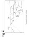
- FIG. 4illustrates an example operation of an autonomous vehicle in accordance with aspects of the disclosure.
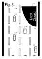
- FIG. 5illustrates further operation of the autonomous vehicle in accordance with aspects of the disclosure.
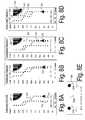
- FIGS. 6A-Cdepict plots of trajectories of vehicles that share the road with the autonomous vehicle.
- FIG. 7depicts an example of a data structure that may be used to store vehicle trajectories in accordance with aspects of the disclosure.
- FIGS. 8A-Edepict plots of the trajectories of vehicles that share the road with the autonomous vehicle, as well as trajectories that are generated by the autonomous vehicle.
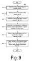
- FIG. 9depicts a flowchart of a process in accordance with aspects of the disclosure.
- FIGS. 10A-Cdepict flowcharts of sub-processes associated with FIG. 9 in accordance with aspects of the disclosure.
- FIG. 11depicts a flowchart of sub-tasks associated with FIGS. 10A-C .
- FIG. 12depicts another flowchart of sub-tasks associated with FIGS. 10A-C .
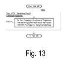
- FIG. 13depicts a further flowchart of sub-tasks associated with FIGS. 10A-C .
- FIG. 14depicts a flowchart of sub-tasks associated with FIG. 9 .
- FIG. 15depicts another flowchart of sub-tasks associated with FIG. 9 .
- FIG. 16depicts a yet another flowchart of sub-tasks associated with FIG. 9 .
- an autonomous vehiclemay use the trajectories of other vehicles on the road to detect lane closures and road blocks. When a large number of vehicles move away from one lane to another, in a given section of road, oftentimes they do so because the former lane is closed.
- the autonomous vehiclemay monitor the other vehicles' trajectories and take the trajectory most traveled. By following the path of other vehicles, the autonomous vehicle may bypass road blocks in the same way vehicles ahead of it did.
- the autonomous vehiclemay perform map updates when road lanes are closed.
- the autonomous vehiclemay calculate a first trajectory based on the other vehicle's trajectories and a second trajectory based on a map. It may then match the two trajectories. A mismatch may indicate that the representation of the road in the map is inaccurate.
- the autonomous vehiclemay take action to correct the map or flag the inaccuracy.
- FIG. 2depicts a schematic diagram of the components of autonomous vehicle 210 in accordance with aspects of the disclosure.
- vehicle 210includes vehicle control unit 220 , braking system 230 , steering system 240 , and acceleration system 250 .
- Vehicle 210is capable of driving from one point to another without (or with partial) input from a human driver.
- vehicle 210is an automobile.
- vehicle 210may be a car, truck, motorcycle, bus, boat, airplane, helicopter, lawnmower, recreational vehicle, amusement park vehicle, farm equipment, construction equipment, tram, golf cart, train, trolley, glider, warehouse equipment, factory equipment, or the like.
- Vehicle control unit 220is a system for controlling the operation of vehicle 210 .
- Vehicle control unit 220may interact with braking system 230 , steering system 240 , and acceleration system 250 to cause vehicle 210 to slow down, stop, steer, or accelerate.
- vehicle control unit 220may include a processor 310 , memory 320 , radio 350 , a camera 360 , and sensor 370 .
- Memory 320 of vehicle control unit 220stores information accessible by processor 310 , including instructions 330 that may be executed by the processor 310 .
- the memoryalso includes data 340 that may be retrieved, manipulated or stored by the processor.
- the memorymay be of any type of tangible media capable of storing information accessible by the processor, such as a hard-drive, memory card, ROM, RAM, DVD, CD-ROM, write-capable, and read-only memories.
- the processor 310may be any well-known processor, such as commercially available processors. Alternatively, the processor may be a dedicated controller such as an ASIC.
- the instructions 330may be any set of instructions to be executed directly (such as machine code) or indirectly (such as scripts) by the processor.
- the terms “instructions,” “steps” and “programs”may be used interchangeably herein.
- the instructionsmay be stored in object code format for direct processing by the processor, or in any other computer language including scripts or collections of independent source code modules that are interpreted on demand or compiled in advance. Functions, methods and routines of the instructions are explained in more detail below.
- Data 340may be retrieved, stored or modified by processor 310 in accordance with the instructions 330 .
- the datamay be stored in computer registers, in a relational database as a table having a plurality of different fields and records, or XML documents.
- the datamay also be formatted in any computer-readable format such as, but not limited to, binary values, ASCII or Unicode.
- the datamay comprise any information sufficient to identify the relevant information, such as numbers, descriptive text, proprietary codes, pointers, references to data stored in other memories (including other network locations) or information that is used by a function to calculate the relevant data.
- FIG. 3functionally illustrates the processor and memory as being within the same block
- the processor and memorymay actually comprise multiple processors and memories that may or may not be stored within the same physical housing.
- some of the instructions and datamay be stored on removable CD-ROM and others within a read-only computer chip.
- Some or all of the instructions and datamay be stored in a location physically remote from, yet still accessible by, the processor.
- the processormay actually comprise a collection of processors which may or may not operate in parallel.
- Sensor 370may include a sensor for detecting pitch, yaw, or roll of vehicle 210 .
- sensor 370may be a laser scanner such, sonar, radar, lidar, or another similar device for detecting obstacles.
- Camera 360is a camera for taking pictures of the surroundings of vehicle 210 . Camera 360 may be used to detect road blocks, road lanes, and other environmental information.
- Radio 350may be an 802.11 transceiver, a 3G transceiver, a communication unit for inter-vehicle communication, or any other type of transceiver for receiving and transmitting information.
- Radio 350may be connected to server 380 over a wireless network.
- the server 380may store information used by the vehicle control unit 220 when controlling the vehicle.
- Such informationmay include maps, information about other vehicles' trajectories, road conditions, climate conditions, and so forth.
- the server 380may receive from vehicle 210 (via radio 350 ) map updates, map corrections, as well as other indication of lane closures.
- the server 380may store the received information in memory or disseminate it among other autonomous vehicles on the road.
- FIG. 4depicts an example of the operation of vehicle 210 in accordance with aspects of the disclosure.
- vehicle 210is traveling on a road 430 .
- Two of the lanes of the roadare closed by road block 420 due to road construction.
- the vehicle 210has to detect that the right two lanes are blocked and move to the leftmost lane.
- FIG. 5shows an example where the vehicle 210 monitors the trajectories of vehicles 510 - 530 in order to detect that the rightmost two lanes of the road 430 are closed by road block 420 .
- vehicle 210may monitor any number of vehicles (e.g., 1, 2, 10, 50).
- Each of the vehicles 510 - 530may be selected for monitoring based on a number of criteria.
- the vehiclesmay be selected based on being within a threshold distance from vehicle 210 .
- the vehiclesmay be selected based on being within the range of a sensor (or camera) on vehicle 210 .
- the vehiclesmay be selected based on them broadcasting a specific type of signal.
- the signalmay be a signal indicating location of the vehicles or, alternatively, it may be a signal containing a vehicle identifier, such as VIN, serial number, MAC or another similar identifier.
- the vehicle identifiermay identify vehicles as either being operated by human drivers or as autonomous vehicles. In that regard, in some aspects, the vehicle 210 may chose to follow the trajectories traveled by human-operated vehicles only or autonomously-operated vehicles only.
- vehicle 210may observe their trajectories in a number of ways.
- vehicle 210may use the camera 360 and image processing software to track the vehicles 510 - 530 .
- curbside sensorsmay be used on the side of the road 430 to detect passing vehicles.
- the vehicles 510 - 530may themselves transmit their geo-location to the vehicle 210 .
- the vehicle trajectoriesmay be obtained from the server 380 . In other words, the vehicle 210 is not limited to any particular technique for tracking other vehicle's trajectories.
- FIGS. 6A-Cdepict plots of trajectories of vehicles 510 - 530 that are observed by the vehicle 210 .
- FIG. 6Adepicts trajectory 610 of vehicle 210 as a collection of solid dots. Each solid dot represents a location passed by the vehicle 510 . A location may be considered passed by the vehicle 510 if the vehicle 510 either drives over or through that location or within a predetermined distance from that location (e.g., 1 meter). Together all dots in the plot trace out a path traveled by the vehicle 510 .
- the trajectories 620 and 630depicted in FIGS. 6B and 6C , indicate the paths traveled by vehicles 520 and 530 , respectively.
- the trajectory 620indicates that the vehicle 520 stayed in right lane until the 80 th meter of road stretch at which point it moved to the middle lane, stayed in the middle lane until it reached the 130 th meter of road stretch, and then moved to the left lane of the road 430 , thereby avoiding the road block 420 .
- the trajectory 630indicates that the vehicle 530 moved from the right lane to the left before it reached the 60 th meter of road stretch and thus it also avoided the road block 420 .
- the arrowhead 210 depicted in FIGS. 6A-6Crepresents the position of the vehicle 210 at the time the trajectories 610 - 630 are processed in the manner discussed with respect to FIGS. 8A-8B .
- FIG. 7depicts an example of a data structure 710 representing the trajectory 610 .
- the trajectory 610is stored as a set of location samples. Each sample is taken at a different time instant. Each sampled location is represented by an X-coordinate and Y-Coordinate.
- the coordinate systemis defined by a Y-axis running in parallel to the left curb of road ( 430 ) and the X-axis is normal to the Y-axis.
- the data structure 710provides only an example of how vehicle trajectories (e.g., observed or generated) may be represented.
- each of the vehicle trajectoriesmay be represented as a set of vectors, collection of coordinates, a polynomial, or any other representation.
- the trajectoriesmay be part of course estimates, road models, and other similar structures used by the vehicle control unit 220 in controlling the operation of the vehicle 210 .
- locations in the trajectory 610are represented as coordinate pairs, in other examples they may be represented as vectors, polynomials, or any other form capable of identifying a location in the environment of vehicle 210 (e.g., road 430 or areas outside the road 430 ).
- the present disclosureis not limited to any specific type of location representations.
- FIGS. 8A-Bdepict plots illustrating some of the processing performed on observed trajectories 610 - 620 in order to produce combined trajectories 810 and 830 .
- FIG. 8Adepicts a plot of observed trajectories 610 and 620 . The plot also shows the location of vehicle 210 (as an arrowhead) relative to the road. As shown on the plot, the trajectory 620 originates in the lane where vehicle 210 is located, whereas the trajectory 610 originates in a different lane. Because it is located in a different lane, the trajectory 610 may be offset.
- FIG. 8Bdepicts a plot of the trajectory 610 after it has been offset.
- the offsettingmay involve identifying the location in trajectory 610 that is the closest, from among all locations in the trajectory 610 , to the location of vehicle 210 and determining a distance between this location and vehicle 210 .
- the distancemay be a Euclidean distance, distance along the X-axis, distance along the Y-axis, or any other type of distance.
- the distanceis added (or subtracted) to all other locations in the trajectory 610 .
- trajectory 610when trajectory 610 is offset, it may be shifted from the center lane to the lane of vehicle 210 .
- the end effect of the offsettingmay be that the trajectories 610 and 620 are normalized into a single lane (e.g., the lane of vehicle 210 ) before being processed further.
- FIG. 8Cdepicts an example of trajectories 810 and 820 .
- Trajectory 810is produced by combining trajectory 610 with trajectory 620 .
- Trajectory 820is generated based on information about the shape of the road 430 that is obtained from a map. In this example, the map is inaccurate and the trajectory 820 leads directly into the road block 420 . By contrast, the combined trajectory 810 safely steers around the road block 420 .
- FIG. 8Ddepicts an example of a combined trajectory 830 that is produced by combining the offset version of trajectory 610 with trajectory 620 .
- a cluster of locationsmay be created that includes the location in the trajectory 610 and one or more corresponding locations from the trajectory 620 .
- the corresponding locationsmay be selected based on being within a threshold distance from the location in trajectory 610 .
- only the location that is the closest to the location in trajectory 610 , from among a group of locations in trajectory 620may be selected as a corresponding location.
- the corresponding locationsare clustered with a location from trajectory 610 based on distance(s) to the location in trajectory 610
- the clusters of locationsmay be assembled based on another characteristic (e.g., location relative to a point outside of the road 430 , successive distances).
- FIG. 8Edepicts an example of locations 840 being combined.
- location 610 a from trajectory 610is combined with location 620 a from trajectory 620 to produce a combined location 830 a of combined trajectory 830 .
- the combined location 830 ais determined by averaging the locations 610 a and 620 a .
- the combined location 830 ais calculated by taking the average of locations 610 a and 620 a , in other examples any method for reducing a cluster of locations, to a single representative location may be used.
- the value of the combined location 830 amay be adjusted based on secondary information.
- the secondary informationmay indicate how reliable trajectories 610 and 620 are.
- the location 830 amay be adjusted by weighing the coordinates of locations 610 a and 620 a with coefficients based on the secondary information.
- each of the coefficients k 1 and k 2may be set somewhere between 0 and 2, thereby adjusting the relative contributions of trajectories 610 and 620 without completely eliminating any one of them.
- the coefficients k1 and k2, in this example,may have any possible value. It should be noted that using coefficient multiplication, in the manner discussed above, is only one of many possibly ways to incorporate secondary information into the calculations of combined locations.
- the secondary informationmay include different reliability characteristics.
- the number of observed trajectories that are combined to generate a combined trajectorymay indicate how reliable the combined trajectory is. The greater the number of observed trajectories, the more reliable the resultant combined trajectory. This is so because, in general, vehicles that are tracked may randomly change lanes without road 430 being blocked. The random lane changes may falsely indicate to vehicle 210 the presence of a road block. However, by increasing the sample of observed trajectories, the effects of random lane changes may be minimized.
- the number of offset trajectories that are combined to generate a combined trajectorymay indicate how reliable the combined trajectory is. The fewer the offset trajectories, the more reliable the combined trajectory. If all the observed trajectories originated from the same lane as the lane in which the vehicle 210 is located, the combined trajectory resulting from the observed trajectories may be considered more reliable. This is so because, unlike vehicles in other lanes, the vehicles in the lane of vehicle 210 face very similar road conditions to those encountered by vehicle 210 .
- the distribution of locations found in a trajectorymay indicate how reliable the trajectory is.
- the statistical attributesmay include variance (e.g., along the X-axis) standard deviation (e.g., along the X-axis), correlation between two sets of locations, standard error (in the set of locations of the combined trajectory), and so forth.
- characteristics of a trajectory's curvaturemay indicate how reliable the trajectory is.
- Curvature characteristicsmay include, the angle of the sharpest turn found in a trajectory, the count of turns that cross a threshold (e.g., turns that are over 90°), the count of left turns, the count of right turns, the presence of patterns of left and right turns (e.g., left turn followed by a right turn followed by a right turn). For example, if a 100° turn is present in a trajectory, this may be an indication that there is an error and the trajectory is unreliable, as vehicles rarely turn 100° when driving on a highway.
- discontinuities a trajectorymay indicate how reliable the trajectory is. The less continuous a trajectory, the less reliable. Discontinuities may be identified based on a distance between successive locations in a given trajectory. The distance may be along the X-axis, Y-axis, Euclidean distance, or any other type of distance. Two locations may be said to be successive if they are located immediately one after another in an ordered set of locations. For example, the locations in the ordered set may be arranged according to the time at which they are measured.
- an example of an ordered set of locationsis depicted in the table 710 .
- the average distance between successive locations in table 710is about +210 m.
- the distance between successive locations t 9 and t 10is ⁇ 50 m.
- a gap of such magnitudemay, in some circumstances, be classified as a discontinuity.
- successive distances in the trajectorymay be compared against a threshold.
- the thresholdmay be a constant (e.g., 50 m) or it may be based on a statistical measure of the successive distances in the set of locations (e.g., standard deviation).
- the amount of discontinuity in a trajectorymay be qualified based on a count of the discontinuities or the value of one or more statistical attributes of the set of successive distances between locations in the trajectory (e.g., average successive distance, standard deviation).
- the reliability characteristics discussed abovemay be used in calculating (or adjusting) the value of combined location 830 a .
- the value of coefficient k 1may be based on one or more reliability characteristics of trajectory 610 and the value of coefficient k 2 may be based one or more reliability characteristics of trajectory 620 .
- the reliability characteristicsmay be used to determine whether at all to use a given trajectory (e.g., combined or observed) in controlling the operation of the vehicle 210 .
- FIG. 9depicts a flowchart of a process 900 for controlling the operation of vehicle 210 by tracking other vehicles' trajectories.
- one or more vehiclesare tracked.
- observed trajectories of the tracked vehiclesare obtained.
- two or more of the observed trajectoriesare processed to generate a first representative trajectory. The generation of the first representative trajectory is discussed further below with respect to FIGS. 10A-C .
- the first representative trajectoryis processed to produce a second representative trajectory. The production of the second representative trajectory is discussed further below with respect to FIGS. 14 and 15 .
- a map updateis performed.
- a trajectorymay be generated based on information from a map (e.g., trajectory 820 ).
- the generated trajectorymay be compared against the first representative trajectory (e.g., trajectory 830 ).
- the mapmay be updated.
- Task 950discussed further below with respect to FIG. 16 .
- vehicle control unit 220changes the state of the vehicle 210 based on one of the first representative trajectory or the second representative trajectory.
- vehicle control unit 220may switch the vehicle 210 to a different control mode. Vehicle may switch to a mode in which it starts relying on cameras and other sensors more heavily.
- vehicle 210may begin following the either the first or second representative trajectory.
- vehicle control unit 220may change one of the speed or direction of the vehicle 210 based on one of the representative trajectories. Vehicle 210 may change lanes to avoid road block 420 or alternatively it may slow down.
- the representative trajectory(first or second) may be included in a control strategy, course estimate, road model, or another similar data structure that is used by the vehicle control unit 220 in controlling the operation of vehicle 210 .
- FIGS. 10A-Care flowcharts of exemplary sub-processes for generating the first representative trajectory as specified by task 930 of FIG. 9 .
- FIG. 10Adepicts exemplary sub-process 1000 A in which an observed trajectory is selected for use as a representative trajectory (task 1010 A).
- the trajectorymay be selected from a group including observed trajectories, offset versions of the observed trajectories, or both.
- the selectionmay be performed according to a selection criterion.
- the selection criterionmay be based on the reliability of the trajectories in the group. For example, the selection criterion may provide that the observed trajectory with the least amount of discontinuity be selected.
- the selection criterionmay be based on reliability characteristics such as those discussed above.
- the observed trajectorymay be selected as the representative trajectory without combining it with another trajectory.
- FIG. 10Bdepicts a flowchart of a process 1000 B in which two or more of the observed trajectories in a group are combined to produce a representative trajectory (task 1010 B).
- the groupmay include observed trajectories, offset versions of the observed trajectories, or both. The manner in which the observed trajectories are combined is discussed further below with respect to FIGS. 11-12 .
- FIG. 10Cdepicts an exemplary sub-process 1000 C in which a representative trajectory is selected from a pool of combined trajectories.
- a group of observed trajectoriesis combined to produce a pool of combined trajectories.
- the group of observed trajectories being combinedmay include observed trajectories, offset versions of the observed trajectories, or both.
- the resulting pool of combined trajectoriesmay include combined trajectories that are generated in a different manner from one another,
- combined trajectories in the poolmay be generated based on different subsets of the group of trajectories,
- each of the combined trajectories in the poolmay be generated by executing an expectation-maximization (EM) process.
- EMexpectation-maximization
- a trajectory from the poolis selected as a representative trajectory.
- the criterion used for the selectionmay be based on one or more of trajectory characteristics that indicate reliability. Exemplary criteria include:
- FIG. 11depicts a flowchart of a sub-process 1100 for combining two or more observed trajectories of vehicles that are tracked as shown by task 1010 B of FIG. 10B .
- a trajectoryis selected as a base trajectory from the trajectories that are being combined.
- a plurality of locations that are part of the base trajectoryis determined.
- a location from the pluralityis selected as a base location.
- location 610 amay be selected.
- each location identified by the base trajectorymay be selected as a base location only once during the execution of the sub-process 1100 .
- a cluster of one or more locationsis determined.
- the clustermay include locations from all trajectories that are being combined except for the base trajectory.
- the clustermay include locations that are within a predetermined distance from the base location.
- the clustermay include only one location from each trajectory that is being combined.
- the latter locationmay be the location closest to the base location from among a group of locations in the trajectory to which the latter location belongs.
- trajectories that are being combinede.g., trajectory 620
- the distance measuredmay be distance along X-axis, distance along Y-axis, Euclidean distance, or any other type of distance.
- location 620 amay be selected.
- a combined locationis calculated based on the base location and the locations from the cluster determined at task 1140 .
- the combined locationmay be generated in the manner discussed with respect to FIG. 8E .
- the combined trajectorymay be an average of the base location and locations from the cluster.
- locations 610 a and 620 amay be combined to generate combined location 830 a.
- the combined locationis included in the combined trajectory that is being generated.
- combined location 830 ais added to the trajectory 830 .
- FIG. 12depicts a flowchart of sub-process 1200 for combining two or more observed trajectories of vehicles that are tracked as shown by task 1010 B of FIG. 10B .
- one of the observed trajectories that are being combinedis selected as an initial base.
- a plurality of locations included in the baseis determined. The plurality may include all or a portion of the locations in the base.
- a location from the pluralityis selected as a base location. In one aspect, each location in the plurality identified at task 1215 may be (or is) selected as a base location only once.
- a cluster of one or more locationsis determined.
- the clustermay include locations from all trajectories that are being combined. However, during the first iteration of the process 1200 , the cluster does not include locations from the trajectory selected as a base at task 1210 .
- the clustermay include locations that are within a predetermined distance from the base location.
- the clustermay include only one location from each trajectory that is being combined. The latter location may be the location closest to the base location from among a group of locations in the trajectory to which the latter location belongs.
- trajectories that are being combinede.g., trajectory 620
- the distance measuredmay be distance along X-axis, distance along Y-axis, Euclidean distance, or any other type of distance.
- a combined locationis calculated based on the base location and the cluster of locations determined at task 1225 .
- the combined locationmay be generated in the manner discussed with respect to FIG. 8E .
- the combined trajectorymay be an average of the base location and locations from the cluster.
- the combined locationis included in a current resultant set.
- task 1240it is determined whether additional locations from the plurality determined at task 1215 remain to be processed. If yes, task 1220 is executed with another location being selected as the “base” location. In some aspects, task 1220 may be repeated once for every location in the set of locations determined at task 1215 . When task 1220 is not to be repeated, task 1245 is performed.
- the convergence criterionmay be based on a number of iterations.
- the convergence criterionmay specify that tasks 1210 - 1240 may be repeated five times at most.
- the convergence criterionmay be based on a distance between the current resultant set and a resultant set generated in a previous iteration.
- the differencemay be determined based on a distance between a first location in the current resultant set and a location from a resultant set that generated in a previous iteration (e.g., the most recent resultant set). If it is determined that the convergence criterion is met, the locations in the current resultant set are included in the combined trajectory that is being generated at task 1250 . Otherwise, task 1255 is executed.
- the current baseis changed.
- the current resultant setis made the current base.
- a new resultant setis generated.
- the new resultant setincludes combined locations that are generated by combining “base locations” from a previously-calculated resultant set with the observed trajectories that are being combined.
- the resultant set that is the outcome of each “outer loop” iteration of the process 1200is refined in subsequent iterations by being combined again and again with the same set of observed trajectories of vehicles that are being tracked.
- FIG. 13depicts an example sub-process 1300 for generating a pool of combined trajectories as specified by task 1020 B.
- the pool of combined trajectoriesis generated based on a set of observed trajectories (task 1310 ).
- the process 1200is executed multiple times. Every time the process 1200 is executed, a different trajectory from the set of combined trajectories is used as an initial base (e.g., at task 1210 ).
- the combined trajectory resulting from each executionis added to pool of combined trajectories.
- all combined trajectories in the poolmay be generated by combining the same trajectories, but with a different trajectory used as an initial base in the process 1200 .
- FIG. 14depicts an exemplary sub-process 1400 for processing the first representative trajectory to produce a second representative trajectory as specified at task 940 of FIG. 9 .
- the first representative trajectory determined at task 930is obtained.
- a reference trajectoryis obtained that is generated based on information other than vehicle trajectory information.
- the reference trajectorymay be generated based on a representation of the road 430 found in a map that is stored in memory 320 .
- the backup trajectorymay be generated by processing information from sensor 370 and camera 360 .
- the reference trajectorymay be generated by using any known method for generating vehicle trajectories, course estimates or vehicle control strategies.
- environmental informationis obtained using, e.g., camera 360 and/or sensor 370 .
- the environmental informationmay include locations of k-rails, obstacles, cones, and other features that provide information about whether the road 430 is blocked.
- a determinationis made of whether the environmental information is consistent with the reference trajectory. For example, if obstacles or cones are detected in the path of the reference trajectory, a determination may be made that the environmental information is inconsistent with the reference trajectory.
- the reference trajectoryis inconsistent with the environmental information, that may be a sign that the reference trajectory is inaccurate and therefore the first (or second) representative trajectory, that is generated based on observed trajectories of other vehicles, should be used in controlling the operation of the vehicle 210 .
- a constraintis obtained.
- the constraintmay specify bounds or a limit for a characteristic of the first representative trajectory.
- the characteristicmay be one of the characteristics that indicate reliability (e.g., curvature characteristic, discontinuity characteristic).
- the constraintmay specify that no turn in a trajectory should exceed ninety degrees.
- the constraintmay specify, that the amount of discontinuity should not exceed a pre-determined threshold.
- the constraintmay specify that the number of turns in a given stretch of road (e.g. 200 m of road) should not exceed a pre-determined number.
- the constraintmay specify that no more than two offset trajectories may be used in generating the first representative trajectory.
- the constraintmay specify ranges for the locations in a given trajectory.
- the constraintmay specify that the horizontal positioning of all locations in a trajectory falls within the ranges (2 m-3 m), (7 m-8 m), (9 m-10 m), These ranges, as FIGS. 6A-C illustrate, may fall within the center portions of the different lanes in road 430 .
- the constraintmay require a degree of similarity between the representative trajectory and target trajectory.
- the target trajectorymay be the reference trajectory, an observed trajectory, an observed trajectory that is used in generating the first representative trajectory, or any other trajectory.
- the similaritymay be defined in terms of distance between a first location in the first representative trajectory and a corresponding second location in the target trajectory.
- the corresponding locationmay be the location in the representative trajectory that is the closest to the first location from among a group of locations in the target trajectory.
- the similaritymay be defined in terms of an average distance between a group of locations in the first trajectory and their corresponding counterparts in the second trajectory.
- the similaritymay be defined in terms of curvature.
- the constraintmay require that for a turn in the first representative trajectory having a given characteristic (e.g., turn angle, starting location, ending location), there be a corresponding turn in the target trajectory that has a characteristic that matches the characteristic of the turn of the first representative trajectory.
- a given characteristice.g., turn angle, starting location, ending location
- the constraintmay require that the first representative trajectory be within a threshold distance from the vehicle 210 .
- the constraintmay specify that the closest point in the first representative trajectory is no further than a threshold distance from vehicle's 210 location.
- a measure of the extent to which the constraint is metis generated.
- the measuremay indicate the degree to which the constraint is met. For example, if the constraint specifies that at least 10 observed trajectories have to be used in generating the first representative trajectory, whereas only 9 have been used, then the measure may indicate that the constraint is barely not met.
- the first representative trajectoryis modified to produce a second representative trajectory.
- the modificationmay involve adjusting one or more of the locations that are part of the first representative trajectory. For example, a location in the first representative trajectory having coordinates (X,Y) may be replaced with a location in the second representative trajectory having coordinates (k1*X, k2*Y), wherein the coefficient k1 and k2 may depend on the measure of extent to which the constraint is met.
- trajectory 810may be shifted from the centerline dividing lane 1 and lane 2 to lane 2. The present disclosure is not limited to any particular method for adjusting one or more of the locations.
- the first trajectorymay be combined with the reference trajectory to generate the second representative trajectory.
- the combinationmay be performed in the manner discussed above with respect to FIGS. 11 and 12 .
- each of the locations in the second representative trajectorymay be determined by selecting a point in the first representative trajectory, identifying a corresponding point in the reference trajectory, and calculating their average.
- the coefficient k 1may be set to 0 while the coefficient k 2 is set to 2, in this case, no weight is given to the reference trajectory.
- the coefficient k 2may set to 0 while k 2 is set to equal 2. In this case, case no weight is given to the first representative trajectory.
- each of the coefficients k 1 and k 2may be set somewhere between 0 and 2, adjusting the contribution of the first representative trajectory and the first trajectory with respect to calculating the second representative trajectory without completely eliminating it. For instance, if the measure of the extent to which a constraint is met is 0.9, k 1 may be set to equal this value thereby lowering the contribution of the first representative trajectory without completely eliminating it.
- the second representative trajectory that is generated at task 1460may be based on the first representative trajectory only, the reference trajectory only, or both the representative trajectory and the reference trajectory.
- the process 1400determines to what extent vehicle 210 is to rely on the trajectories of other vehicles on the road 430 or on conventional information, such as maps, sensor feedback, and so forth. The determination is made based on decisions about whether constraints are met and information from cameras, laser scanners, and other similar sensors.
- FIG. 15depicts an exemplary sub-process 1500 for processing the first representative trajectory to produce a second representative trajectory, as specified by task 960 of FIG. 9 .
- the second representative trajectorymay be an improved version of the first representative trajectory.
- the first representative trajectory determined at task 930is obtained.
- environmental informationis obtained using, e.g., camera 360 and/or sensor 370 .
- the environmental informationmay include locations of k-rails, obstacles, cones, and other features that provide information about whether the road 430 is blocked.
- Task 1520is identical to task 1430 .
- a constraintis obtained.
- the constraintmay specify bounds or a limit for a characteristic of the first representative trajectory.
- the obtained constraintmay be any of the constraints discussed with respect to task 1440 , such as a constraint that specifies ranges for locations in the first representative trajectory or a constraint based on the number of turns in the first representative trajectory.
- the constraintmay require a consistency between the first representative trajectory and the environmental information obtained at task 1520 . For example, the constraint may specify that no location in the first representative trajectory should be closer than a predetermined distance from an obstacle on the road that is detected using the camera 360 or sensor 370 .
- the first representative trajectoryis modified to produce a second representative trajectory.
- the second representative trajectorymay be an improved version of the first representative trajectory and its generation may involve adjusting one or more of the locations that are part of the first representative trajectory.
- a location in the first representative trajectory having coordinates (X,Y)may be replaced in the second representative trajectory with a location having coordinates (k 1 *X, k 2 *Y), wherein the coefficients k 1 and k 2 may depend on environmental information obtained at task 1520 or a measure of extent to which a constraint obtained at task 1530 constraint is met.
- the process 1500is an example of one of many possible ways of combining information regarding observed vehicle trajectories with additional (environment) information in order to produce an improved trajectory estimate.
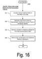
- FIG. 16depicts an example sub-process 1600 for performing a map update as specified by task 960 of FIG. 9 .
- a backup trajectoryis generated based on information from a map.
- a first portion of the first representative trajectory(generated at task 930 ) is identified along with a second portion of the backup trajectory.
- the first portionmay include all or fewer of the locations in the first trajectory.
- the second portionmay include all or fewer of the locations in the backup trajectory.
- a measure of discrepancyis determined between the first portion and the second portion.
- the measureis based on distance between locations in the two portions.
- the measuremay be based on the distance between a first location from the first portion and location(s) from the second portion that correspond to the first portion (e.g., distance to the closest of all locations).
- the measuremay be based on the average distances between locations in the first portion and their corresponding locations in the second portion.
- the measuremay be based on characteristics of turns indicated by the first trajectory (e.g., location, angle). The greater the one of the above distances, the greater the measure of the discrepancy. Similarly, the greater the difference in the characteristics of correspond turns in the two portions, the greater the measure of discrepancy.
- a map updatemay be performed.
- the map updateis performed only if the measure of discrepancy determined at task 1640 exceeds the threshold. For example, if any of the calculated distances (e.g., average distance or distance between two points is greater than 10 meters, the map update is performed).
- the map updatemay involve modifying a map that is stored in memory 320 to show that the road 430 is likely blocked, changing a representation of the shape of the geometry (e.g., shape) to conform to the shape of the representative trajectory, or storing an indication in memory 320 that the map is inaccurate.
- performing an updatemay involve transmitting a message to the server 380 instructing to modify a map or simply alerting it that the map may be inaccurate.
- FIGS. 1-16are provided as examples only. At least some of the tasks may be performed in a different order than represented, performed concurrently or altogether omitted.
- the ideas and concepts of this disclosuremay find application in traction control systems, collision detections systems, and other passive or active systems found in vehicles.
- the vehicle trajectory informationmay be used to update road maps or for real-time road conditions monitoring.
- the aforementioned featuresmay be implemented either in software as part of instructions 330 executed by a processing device, such as a processor, or in hardware (e.g., using FPGA), or both in software and hardware.
- the present disclosureis not limited to any particular software or hardware implementation.
Landscapes
- Engineering & Computer Science (AREA)
- Automation & Control Theory (AREA)
- Physics & Mathematics (AREA)
- Transportation (AREA)
- Mechanical Engineering (AREA)
- Radar, Positioning & Navigation (AREA)
- Remote Sensing (AREA)
- General Physics & Mathematics (AREA)
- Aviation & Aerospace Engineering (AREA)
- Combustion & Propulsion (AREA)
- Chemical & Material Sciences (AREA)
- Mathematical Physics (AREA)
- Life Sciences & Earth Sciences (AREA)
- Atmospheric Sciences (AREA)
- Business, Economics & Management (AREA)
- Health & Medical Sciences (AREA)
- Artificial Intelligence (AREA)
- Evolutionary Computation (AREA)
- Game Theory and Decision Science (AREA)
- Medical Informatics (AREA)
- Human Computer Interaction (AREA)
- Traffic Control Systems (AREA)
Abstract
Description
- R1: Select the combined trajectory that is generated based on the largest number of observed trajectories.
- R2: Select the combined trajectory that is generated based on the smallest number of offset observed trajectories.
- R3: Select a combined trajectory that has the smallest standard error associated with the combined trajectory's set of locations.
- R4: Select a trajectory where no turn exceeds a pre-determined threshold angle (e.g., 90°).
- R5: Select the combined trajectory with the lowest amount of discontinuity.
Claims (19)
Priority Applications (6)
| Application Number | Priority Date | Filing Date | Title |
|---|---|---|---|
| US13/422,688US8825265B1 (en) | 2012-03-16 | 2012-03-16 | Approach for consolidating observed vehicle trajectories into a single representative trajectory |
| US14/449,792US9459625B1 (en) | 2012-03-16 | 2014-08-01 | Approach for consolidating observed vehicle trajectories into a single representative trajectory |
| US15/216,199US10012991B1 (en) | 2012-03-16 | 2016-07-21 | Approach for consolidating observed vehicle trajectories into a single representative trajectory |
| US15/976,179US10852733B1 (en) | 2012-03-16 | 2018-05-10 | Approach for consolidating observed vehicle trajectories into a single representative trajectory |
| US17/081,084US11402841B1 (en) | 2012-03-16 | 2020-10-27 | Approach for consolidating observed vehicle trajectories into a single representative trajectory |
| US17/849,821US11921510B1 (en) | 2012-03-16 | 2022-06-27 | Approach for consolidating observed vehicle trajectories into a single representative trajectory |
Applications Claiming Priority (1)
| Application Number | Priority Date | Filing Date | Title |
|---|---|---|---|
| US13/422,688US8825265B1 (en) | 2012-03-16 | 2012-03-16 | Approach for consolidating observed vehicle trajectories into a single representative trajectory |
Related Child Applications (1)
| Application Number | Title | Priority Date | Filing Date |
|---|---|---|---|
| US14/449,792ContinuationUS9459625B1 (en) | 2012-03-16 | 2014-08-01 | Approach for consolidating observed vehicle trajectories into a single representative trajectory |
Publications (1)
| Publication Number | Publication Date |
|---|---|
| US8825265B1true US8825265B1 (en) | 2014-09-02 |
Family
ID=51400080
Family Applications (6)
| Application Number | Title | Priority Date | Filing Date |
|---|---|---|---|
| US13/422,688Active2032-10-27US8825265B1 (en) | 2012-03-16 | 2012-03-16 | Approach for consolidating observed vehicle trajectories into a single representative trajectory |
| US14/449,792Active2032-05-19US9459625B1 (en) | 2012-03-16 | 2014-08-01 | Approach for consolidating observed vehicle trajectories into a single representative trajectory |
| US15/216,199ActiveUS10012991B1 (en) | 2012-03-16 | 2016-07-21 | Approach for consolidating observed vehicle trajectories into a single representative trajectory |
| US15/976,179Active2032-05-17US10852733B1 (en) | 2012-03-16 | 2018-05-10 | Approach for consolidating observed vehicle trajectories into a single representative trajectory |
| US17/081,084ActiveUS11402841B1 (en) | 2012-03-16 | 2020-10-27 | Approach for consolidating observed vehicle trajectories into a single representative trajectory |
| US17/849,821ActiveUS11921510B1 (en) | 2012-03-16 | 2022-06-27 | Approach for consolidating observed vehicle trajectories into a single representative trajectory |
Family Applications After (5)
| Application Number | Title | Priority Date | Filing Date |
|---|---|---|---|
| US14/449,792Active2032-05-19US9459625B1 (en) | 2012-03-16 | 2014-08-01 | Approach for consolidating observed vehicle trajectories into a single representative trajectory |
| US15/216,199ActiveUS10012991B1 (en) | 2012-03-16 | 2016-07-21 | Approach for consolidating observed vehicle trajectories into a single representative trajectory |
| US15/976,179Active2032-05-17US10852733B1 (en) | 2012-03-16 | 2018-05-10 | Approach for consolidating observed vehicle trajectories into a single representative trajectory |
| US17/081,084ActiveUS11402841B1 (en) | 2012-03-16 | 2020-10-27 | Approach for consolidating observed vehicle trajectories into a single representative trajectory |
| US17/849,821ActiveUS11921510B1 (en) | 2012-03-16 | 2022-06-27 | Approach for consolidating observed vehicle trajectories into a single representative trajectory |
Country Status (1)
| Country | Link |
|---|---|
| US (6) | US8825265B1 (en) |
Cited By (66)
| Publication number | Priority date | Publication date | Assignee | Title |
|---|---|---|---|---|
| US20140358420A1 (en)* | 2013-05-28 | 2014-12-04 | Hyundai Motor Company | Apparatus and method for detecting traffic lane using wireless communication |
| US20150158469A1 (en)* | 2013-12-06 | 2015-06-11 | Elwha Llc | Systems and methods for determining a robotic status of a driving vehicle |
| US20150286219A1 (en)* | 2012-10-29 | 2015-10-08 | Audi Ag | Method for coordinating the operation of motor vehicles that drive in fully automated mode |
| US9459625B1 (en)* | 2012-03-16 | 2016-10-04 | Google Inc. | Approach for consolidating observed vehicle trajectories into a single representative trajectory |
| US9460622B1 (en)* | 2012-03-16 | 2016-10-04 | Google Inc. | Approach for estimating the geometry of roads and lanes by using vehicle trajectories |
| US9494439B1 (en) | 2015-05-13 | 2016-11-15 | Uber Technologies, Inc. | Autonomous vehicle operated with guide assistance of human driven vehicles |
| WO2016183525A1 (en)* | 2015-05-13 | 2016-11-17 | Uber Technologies, Inc. | Autonomous vehicle operated with guide assistance |
| WO2016186719A1 (en)* | 2015-05-20 | 2016-11-24 | Delphi Technologies, Inc. | System for auto-updating route-data used by a plurality of automated vehicles |
| US9547309B2 (en) | 2015-05-13 | 2017-01-17 | Uber Technologies, Inc. | Selecting vehicle type for providing transport |
| US9562779B2 (en)* | 2014-12-23 | 2017-02-07 | Here Global B.V. | Method and apparatus for providing a steering reliability map based on driven curvatures and geometry curvature |
| US9625264B1 (en)* | 2016-01-20 | 2017-04-18 | Denso Corporation | Systems and methods for displaying route information |
| FR3052130A1 (en)* | 2016-06-02 | 2017-12-08 | Peugeot Citroen Automobiles Sa | ASSISTANCE METHOD FOR A SELF-CONTAINING VEHICLE CIRCULATING ON A MODIFIED CIRCULATION PATH |
| WO2017220286A1 (en)* | 2016-06-21 | 2017-12-28 | Audi Ag | Method for operating a vehicle system designed to determine a trajectory to be followed and/or to perform driving interventions, method for operating a control system, and motor vehicle |
| WO2018038958A3 (en)* | 2016-08-24 | 2018-04-05 | Uber Technologies, Inc. | Hybrid trip planning for autonomous vehicles |
| US9953283B2 (en) | 2015-11-20 | 2018-04-24 | Uber Technologies, Inc. | Controlling autonomous vehicles in connection with transport services |
| US20180329428A1 (en)* | 2017-05-09 | 2018-11-15 | Uber Technologies, Inc. | Navigational constraints for autonomous vehicles |
| US10139828B2 (en) | 2015-09-24 | 2018-11-27 | Uber Technologies, Inc. | Autonomous vehicle operated with safety augmentation |
| CN109085837A (en)* | 2018-08-30 | 2018-12-25 | 百度在线网络技术(北京)有限公司 | Control method for vehicle, device, computer equipment and storage medium |
| JP2019048518A (en)* | 2017-09-08 | 2019-03-28 | 株式会社Subaru | Notification device |
| JP2019053545A (en)* | 2017-09-15 | 2019-04-04 | トヨタ自動車株式会社 | Traffic volume determination system, traffic volume determination method, and traffic volume determination program |
| US10254121B2 (en) | 2017-01-23 | 2019-04-09 | Uber Technologies, Inc. | Dynamic routing for self-driving vehicles |
| US10296001B2 (en) | 2016-10-27 | 2019-05-21 | Uber Technologies, Inc. | Radar multipath processing |
| US10303173B2 (en) | 2016-05-27 | 2019-05-28 | Uber Technologies, Inc. | Facilitating rider pick-up for a self-driving vehicle |
| CN109952547A (en)* | 2016-11-18 | 2019-06-28 | 奥迪股份公司 | Automatic control and motor vehicle according to lane data to motor vehicle |
| US10345809B2 (en) | 2015-05-13 | 2019-07-09 | Uber Technologies, Inc. | Providing remote assistance to an autonomous vehicle |
| US10452068B2 (en) | 2016-10-17 | 2019-10-22 | Uber Technologies, Inc. | Neural network system for autonomous vehicle control |
| US10474162B2 (en) | 2016-07-01 | 2019-11-12 | Uatc, Llc | Autonomous vehicle localization using passive image data |
| CN110580042A (en)* | 2019-08-12 | 2019-12-17 | 西安电子科技大学 | A Hybrid Distributed Motion Control Method for Multi-Robot System |
| US10580296B2 (en) | 2016-12-06 | 2020-03-03 | Nissan North America, Inc. | Advanced threat warning for autonomous vehicles |
| US10662696B2 (en) | 2015-05-11 | 2020-05-26 | Uatc, Llc | Detecting objects within a vehicle in connection with a service |
| CN111272180A (en)* | 2018-12-04 | 2020-06-12 | 赫尔环球有限公司 | Method and apparatus for estimating a positioning location on a map |
| US10684361B2 (en) | 2015-12-16 | 2020-06-16 | Uatc, Llc | Predictive sensor array configuration system for an autonomous vehicle |
| US10712742B2 (en) | 2015-12-16 | 2020-07-14 | Uatc, Llc | Predictive sensor array configuration system for an autonomous vehicle |
| US10712160B2 (en) | 2015-12-10 | 2020-07-14 | Uatc, Llc | Vehicle traction map for autonomous vehicles |
| CN111444294A (en)* | 2019-01-17 | 2020-07-24 | 杭州海康威视系统技术有限公司 | Track completion method and device and electronic equipment |
| US10726280B2 (en) | 2016-03-09 | 2020-07-28 | Uatc, Llc | Traffic signal analysis system |
| US20200346691A1 (en)* | 2018-09-28 | 2020-11-05 | Baidu Usa Llc | Control dominated three-point turn planning for autonomous driving vehicles |
| CN112172837A (en)* | 2020-09-27 | 2021-01-05 | 苏州交驰人工智能研究院有限公司 | A vehicle control method and related device |
| FR3098584A1 (en)* | 2019-07-10 | 2021-01-15 | Psa Automobiles Sa | Method and system for determining a recommended path that a motor vehicle can follow through a space using a roadside unit of an intelligent transportation system |
| US10909866B2 (en) | 2018-07-20 | 2021-02-02 | Cybernet Systems Corp. | Autonomous transportation system and methods |
| US10908608B2 (en)* | 2018-01-18 | 2021-02-02 | Baidu Usa Llc | Method and system for stitching planning trajectories from consecutive planning cycles for smooth control execution of autonomous driving vehicles |
| CN112313133A (en)* | 2018-04-11 | 2021-02-02 | 欧若拉创新公司 | Controlling an autonomous vehicle based on a determined yaw parameter of an additional vehicle |
| US10948924B2 (en) | 2015-02-06 | 2021-03-16 | Aptiv Technologies Limited | Method and apparatus for controlling an autonomous vehicle |
| US10991247B2 (en) | 2015-02-06 | 2021-04-27 | Aptiv Technologies Limited | Method of automatically controlling an autonomous vehicle based on electronic messages from roadside infrastructure or other vehicles |
| US10989538B2 (en) | 2017-12-15 | 2021-04-27 | Uatc, Llc | IMU data offset compensation for an autonomous vehicle |
| US11068724B2 (en)* | 2018-10-11 | 2021-07-20 | Baidu Usa Llc | Deep learning continuous lane lines detection system for autonomous vehicles |
| US11079761B2 (en)* | 2018-12-12 | 2021-08-03 | Ford Global Technologies, Llc | Vehicle path processing |
| CN113635912A (en)* | 2021-09-10 | 2021-11-12 | 阿波罗智能技术(北京)有限公司 | Vehicle control method, device, equipment, storage medium and automatic driving vehicle |
| US20210380095A1 (en)* | 2020-06-04 | 2021-12-09 | Beijing Baidu Netcom Science And Technology Co., Ltd. | Method for generating parking model, electronic device, and storage medium |
| US11287816B2 (en) | 2018-06-11 | 2022-03-29 | Uatc, Llc | Navigational constraints for autonomous vehicles |
| US11299144B2 (en)* | 2016-05-23 | 2022-04-12 | Robert Bosch Gmbh | Method for providing vehicle-trajectory information and method for locating a pothole |
| US11308802B2 (en)* | 2017-06-28 | 2022-04-19 | Audi Ag | Method for the at least partially automated operation of a motor vehicle |
| US11334753B2 (en) | 2018-04-30 | 2022-05-17 | Uatc, Llc | Traffic signal state classification for autonomous vehicles |
| CN114763164A (en)* | 2021-01-12 | 2022-07-19 | 本田技研工业株式会社 | Vehicle control system and vehicle control method |
| US11420652B2 (en)* | 2019-08-30 | 2022-08-23 | Deere & Company | System and method of control for autonomous or remote-controlled vehicle platform |
| US20220282976A1 (en)* | 2019-08-22 | 2022-09-08 | Thales | Method for determining a flight distance of an aircraft over a discontinuity segment, associated method for determining a trajectory, computer program product and determination module |
| US20220297695A1 (en)* | 2021-03-17 | 2022-09-22 | Honda Motor Co., Ltd. | Mobile object control device, mobile object control method, and storage medium |
| CN115112138A (en)* | 2022-05-10 | 2022-09-27 | 阿波罗智联(北京)科技有限公司 | Trajectory planning information generation method, device, electronic device, and storage medium |
| US20220410939A1 (en)* | 2021-09-02 | 2022-12-29 | Beijing Baidu Netcom Science Technology Co., Ltd. | Collision detection method, electronic device, and medium |
| US11566906B2 (en)* | 2019-10-01 | 2023-01-31 | Here Global B.V. | Method, apparatus, and system for generating vehicle paths in a limited graph area |
| US20230177839A1 (en)* | 2021-12-02 | 2023-06-08 | Nvidia Corporation | Deep learning based operational domain verification using camera-based inputs for autonomous systems and applications |
| US11713975B2 (en)* | 2018-11-26 | 2023-08-01 | Uber Technologies, Inc. | Routing graph management in autonomous vehicle routing |
| GB2615101A (en)* | 2022-01-27 | 2023-08-02 | Aptiv Tech Ltd | Method for generating high definition maps, and cloud server and vehicle |
| US11815904B2 (en) | 2017-03-20 | 2023-11-14 | Mobileye Vision Technologies Ltd. | Trajectory selection for an autonomous vehicle |
| US12153961B2 (en) | 2015-09-24 | 2024-11-26 | Aurora Operations, Inc. | Autonomous vehicle operated with safety augmentation |
| US12384376B2 (en)* | 2022-03-31 | 2025-08-12 | Honda Motor Co., Ltd. | Vehicle system, control method, and storage medium |
Families Citing this family (14)
| Publication number | Priority date | Publication date | Assignee | Title |
|---|---|---|---|---|
| US10489663B2 (en)* | 2017-04-24 | 2019-11-26 | Toyota Research Institute, Inc. | Systems and methods for identifying changes within a mapped environment |
| CN109507997B (en)* | 2017-09-15 | 2021-11-12 | 现代摩比斯株式会社 | Apparatus, method and system for automatic driving |
| JP6766798B2 (en)* | 2017-12-15 | 2020-10-14 | 株式会社デンソー | Road map generation system and road map generation method |
| CN109703568B (en)* | 2019-02-19 | 2020-08-18 | 百度在线网络技术(北京)有限公司 | Method, device and server for learning driving strategy of automatic driving vehicle in real time |
| DE102020112036A1 (en)* | 2020-05-05 | 2021-11-11 | Valeo Schalter Und Sensoren Gmbh | DRIVER ASSISTANCE FOR A MOTOR VEHICLE |
| JP7619120B2 (en)* | 2021-03-25 | 2025-01-22 | トヨタ自動車株式会社 | Cruise control device, cruise control method, and computer program |
| DE102021203186A1 (en)* | 2021-03-30 | 2022-10-06 | Continental Teves Ag & Co. Ohg | Method and warning device for warning a following vehicle on a defined roadway section of an obstacle. |
| CN113030934B (en)* | 2021-05-20 | 2021-08-20 | 江苏金晓电子信息股份有限公司 | Vehicle inspection radar data preprocessing method based on average distance nearest principle |
| CN113033030B (en)* | 2021-05-25 | 2021-08-03 | 四川见山科技有限责任公司 | A congestion simulation method and system based on real road scene |
| US12358528B2 (en)* | 2022-04-26 | 2025-07-15 | Toyota Research Institute, Inc. | Producing a trajectory from a diverse set of possible movements |
| EP4300458A1 (en)* | 2022-06-27 | 2024-01-03 | Aptiv Technologies Limited | Method and device for determining at least one characteristic of a flow of traffic |
| DE102022207651B4 (en) | 2022-07-26 | 2024-10-17 | Volkswagen Aktiengesellschaft | Creating a logical network of paths in parking spaces |
| CN115416692A (en)* | 2022-09-30 | 2022-12-02 | 浙江吉利控股集团有限公司 | A kind of automatic driving method, device and electronic equipment |
| CN119796249A (en)* | 2025-01-02 | 2025-04-11 | 北汽福田汽车股份有限公司 | Method, device, vehicle and medium for determining vehicle parameters |
Citations (9)
| Publication number | Priority date | Publication date | Assignee | Title |
|---|---|---|---|---|
| US6169940B1 (en)* | 1997-09-03 | 2001-01-02 | Honda Giken Kogyo Kabushiki Kaisha | Automatic driving system |
| US6600991B1 (en)* | 2001-08-14 | 2003-07-29 | The United States Of America As Represented By The Administrator Of The National Aeronautics And Space Administration | Neighboring optimal aircraft guidance in a general wind environment |
| WO2004072753A1 (en)* | 2003-02-15 | 2004-08-26 | Yong-Kwon Choi | System and method for generating steering angle data of an automatic navigation vehicle via image tracking of a leading vehicle |
| US6963795B2 (en)* | 2002-07-16 | 2005-11-08 | Honeywell Interntaional Inc. | Vehicle position keeping system |
| US7024309B2 (en)* | 2003-08-28 | 2006-04-04 | The United States Of America As Represented By The Secretary Of The Air Force | Autonomous station keeping system for formation flight |
| US20070070069A1 (en)* | 2005-09-26 | 2007-03-29 | Supun Samarasekera | System and method for enhanced situation awareness and visualization of environments |
| US7617037B2 (en)* | 2001-12-05 | 2009-11-10 | Daimler Ag | System for automatically monitoring a motor vehicle |
| US20100168937A1 (en)* | 2005-08-09 | 2010-07-01 | Eads Deutschland Gmbh | Method for Flight Control of a Plurality of Aircraft Flying in Formation |
| US20100256836A1 (en)* | 2009-04-06 | 2010-10-07 | Gm Global Technology Operations, Inc. | Autonomous vehicle management |
Family Cites Families (16)
| Publication number | Priority date | Publication date | Assignee | Title |
|---|---|---|---|---|
| JP3144151B2 (en)* | 1993-05-12 | 2001-03-12 | オムロン株式会社 | Traffic flow abnormality detection device |
| US7188026B2 (en)* | 2003-05-12 | 2007-03-06 | Dash Navigation, Inc. | Hierarchical floating car data network |
| WO2006126400A1 (en)* | 2005-05-24 | 2006-11-30 | Pioneer Corporation | Traffic information processing device, traffic information processing method, traffic information processing program, and recording medium containing the program |
| WO2007102367A1 (en)* | 2006-02-28 | 2007-09-13 | Toyota Jidosha Kabushiki Kaisha | Object course prediction method, device, program, and automatic driving system |
| US8483903B2 (en)* | 2006-09-07 | 2013-07-09 | Nissan North America, Inc. | Vehicle on-board unit |
| JP4450023B2 (en)* | 2007-07-12 | 2010-04-14 | トヨタ自動車株式会社 | Own vehicle risk acquisition device |
| JP2011048470A (en)* | 2009-08-25 | 2011-03-10 | Toyota Motor Corp | Environment prediction device |
| US9696169B2 (en)* | 2010-03-19 | 2017-07-04 | General Motors Llc | Method of detecting the opening of closed roads |
| US8509982B2 (en)* | 2010-10-05 | 2013-08-13 | Google Inc. | Zone driving |
| CN102231235B (en)* | 2011-04-29 | 2016-02-24 | 陈伟 | A kind of traffic flow outlier detection localization method |
| CN104012123A (en)* | 2011-12-30 | 2014-08-27 | 英特尔公司 | Wireless network for sharing road information |
| US9187117B2 (en)* | 2012-01-17 | 2015-11-17 | Ford Global Technologies, Llc | Autonomous lane control system |
| US8825265B1 (en)* | 2012-03-16 | 2014-09-02 | Google Inc. | Approach for consolidating observed vehicle trajectories into a single representative trajectory |
| US8880272B1 (en)* | 2012-03-16 | 2014-11-04 | Google Inc. | Approach for estimating the geometry of roads and lanes by using vehicle trajectories |
| US8996228B1 (en)* | 2012-09-05 | 2015-03-31 | Google Inc. | Construction zone object detection using light detection and ranging |
| JP7205773B2 (en)* | 2019-03-27 | 2023-01-17 | スズキ株式会社 | Vehicle travel control device |
- 2012
- 2012-03-16USUS13/422,688patent/US8825265B1/enactiveActive
- 2014
- 2014-08-01USUS14/449,792patent/US9459625B1/enactiveActive
- 2016
- 2016-07-21USUS15/216,199patent/US10012991B1/enactiveActive
- 2018
- 2018-05-10USUS15/976,179patent/US10852733B1/enactiveActive
- 2020
- 2020-10-27USUS17/081,084patent/US11402841B1/enactiveActive
- 2022
- 2022-06-27USUS17/849,821patent/US11921510B1/enactiveActive
Patent Citations (9)
| Publication number | Priority date | Publication date | Assignee | Title |
|---|---|---|---|---|
| US6169940B1 (en)* | 1997-09-03 | 2001-01-02 | Honda Giken Kogyo Kabushiki Kaisha | Automatic driving system |
| US6600991B1 (en)* | 2001-08-14 | 2003-07-29 | The United States Of America As Represented By The Administrator Of The National Aeronautics And Space Administration | Neighboring optimal aircraft guidance in a general wind environment |
| US7617037B2 (en)* | 2001-12-05 | 2009-11-10 | Daimler Ag | System for automatically monitoring a motor vehicle |
| US6963795B2 (en)* | 2002-07-16 | 2005-11-08 | Honeywell Interntaional Inc. | Vehicle position keeping system |
| WO2004072753A1 (en)* | 2003-02-15 | 2004-08-26 | Yong-Kwon Choi | System and method for generating steering angle data of an automatic navigation vehicle via image tracking of a leading vehicle |
| US7024309B2 (en)* | 2003-08-28 | 2006-04-04 | The United States Of America As Represented By The Secretary Of The Air Force | Autonomous station keeping system for formation flight |
| US20100168937A1 (en)* | 2005-08-09 | 2010-07-01 | Eads Deutschland Gmbh | Method for Flight Control of a Plurality of Aircraft Flying in Formation |
| US20070070069A1 (en)* | 2005-09-26 | 2007-03-29 | Supun Samarasekera | System and method for enhanced situation awareness and visualization of environments |
| US20100256836A1 (en)* | 2009-04-06 | 2010-10-07 | Gm Global Technology Operations, Inc. | Autonomous vehicle management |
Non-Patent Citations (1)
| Title |
|---|
| Sarholz et al., Evaluation of Different Approaches for Road Course Estimation using Imaging Radar, 2011 IEEE/RSJ International conferfence on Intelligent Robots and Systems, Sep. 25-30, 2011, San Francisco, CA, USA. |
Cited By (120)
| Publication number | Priority date | Publication date | Assignee | Title |
|---|---|---|---|---|
| US11402841B1 (en)* | 2012-03-16 | 2022-08-02 | Waymo Llc | Approach for consolidating observed vehicle trajectories into a single representative trajectory |
| US10852733B1 (en) | 2012-03-16 | 2020-12-01 | Waymo Llc | Approach for consolidating observed vehicle trajectories into a single representative trajectory |
| US10012991B1 (en)* | 2012-03-16 | 2018-07-03 | Waymo Llc | Approach for consolidating observed vehicle trajectories into a single representative trajectory |
| US9459625B1 (en)* | 2012-03-16 | 2016-10-04 | Google Inc. | Approach for consolidating observed vehicle trajectories into a single representative trajectory |
| US9460622B1 (en)* | 2012-03-16 | 2016-10-04 | Google Inc. | Approach for estimating the geometry of roads and lanes by using vehicle trajectories |
| US11921510B1 (en)* | 2012-03-16 | 2024-03-05 | Waymo Llc | Approach for consolidating observed vehicle trajectories into a single representative trajectory |
| US20150286219A1 (en)* | 2012-10-29 | 2015-10-08 | Audi Ag | Method for coordinating the operation of motor vehicles that drive in fully automated mode |
| US9442489B2 (en)* | 2012-10-29 | 2016-09-13 | Audi Ag | Method for coordinating the operation of motor vehicles that drive in fully automated mode |
| US20140358420A1 (en)* | 2013-05-28 | 2014-12-04 | Hyundai Motor Company | Apparatus and method for detecting traffic lane using wireless communication |
| US9273971B2 (en)* | 2013-05-28 | 2016-03-01 | Hyundai Motor Company | Apparatus and method for detecting traffic lane using wireless communication |
| US9707942B2 (en)* | 2013-12-06 | 2017-07-18 | Elwha Llc | Systems and methods for determining a robotic status of a driving vehicle |
| US20150158469A1 (en)* | 2013-12-06 | 2015-06-11 | Elwha Llc | Systems and methods for determining a robotic status of a driving vehicle |
| US9562779B2 (en)* | 2014-12-23 | 2017-02-07 | Here Global B.V. | Method and apparatus for providing a steering reliability map based on driven curvatures and geometry curvature |
| US20170102703A1 (en)* | 2014-12-23 | 2017-04-13 | Here Global B.V. | Method and apparatus for providing a steering reliability map based on driven curvatures and geometry curvature |
| US9880555B2 (en)* | 2014-12-23 | 2018-01-30 | Here Global B.V. | Method and apparatus for providing a steering reliability map based on driven curvatures and geometry curvature |
| US11543832B2 (en) | 2015-02-06 | 2023-01-03 | Aptiv Technologies Limited | Method and apparatus for controlling an autonomous vehicle |
| US11763670B2 (en) | 2015-02-06 | 2023-09-19 | Aptiv Technologies Limited | Method of automatically controlling an autonomous vehicle based on electronic messages from roadside infrastructure or other vehicles |
| US10991247B2 (en) | 2015-02-06 | 2021-04-27 | Aptiv Technologies Limited | Method of automatically controlling an autonomous vehicle based on electronic messages from roadside infrastructure or other vehicles |
| US10948924B2 (en) | 2015-02-06 | 2021-03-16 | Aptiv Technologies Limited | Method and apparatus for controlling an autonomous vehicle |
| US11505984B2 (en) | 2015-05-11 | 2022-11-22 | Uber Technologies, Inc. | Detecting objects within a vehicle in connection with a service |
| US10662696B2 (en) | 2015-05-11 | 2020-05-26 | Uatc, Llc | Detecting objects within a vehicle in connection with a service |
| US11403683B2 (en) | 2015-05-13 | 2022-08-02 | Uber Technologies, Inc. | Selecting vehicle type for providing transport |
| RU2726238C2 (en)* | 2015-05-13 | 2020-07-10 | ЮЭйТиСи, ЭлЭлСи | Self-contained vehicle with direction support |
| US9940651B2 (en) | 2015-05-13 | 2018-04-10 | Uber Technologies, Inc. | Selecting vehicle type for providing transport |
| US10037553B2 (en) | 2015-05-13 | 2018-07-31 | Uber Technologies, Inc. | Selecting vehicle type for providing transport |
| US10126742B2 (en) | 2015-05-13 | 2018-11-13 | Uber Technologies, Inc. | Autonomous vehicle operated with guide assistance of human driven vehicles |
| US9933779B2 (en) | 2015-05-13 | 2018-04-03 | Uber Technologies, Inc. | Autonomous vehicle operated with guide assistance of human driven vehicles |
| US10990094B2 (en) | 2015-05-13 | 2021-04-27 | Uatc, Llc | Autonomous vehicle operated with guide assistance of human driven vehicles |
| US12073446B2 (en) | 2015-05-13 | 2024-08-27 | Uber Technologies, Inc. | Systems and methods for managing an autonomous vehicle transport service |
| US10163139B2 (en) | 2015-05-13 | 2018-12-25 | Uber Technologies, Inc. | Selecting vehicle type for providing transport |
| CN107850895A (en)* | 2015-05-13 | 2018-03-27 | 优步技术公司 | Autonomous vehicle with guidance assistance |
| AU2016262563B2 (en)* | 2015-05-13 | 2019-03-14 | Uber Technologies, Inc. | Autonomous vehicle operated with guide assistance |
| US9494439B1 (en) | 2015-05-13 | 2016-11-15 | Uber Technologies, Inc. | Autonomous vehicle operated with guide assistance of human driven vehicles |
| WO2016183525A1 (en)* | 2015-05-13 | 2016-11-17 | Uber Technologies, Inc. | Autonomous vehicle operated with guide assistance |
| CN107850895B (en)* | 2015-05-13 | 2020-03-31 | 优步技术公司 | Autonomous vehicle with guidance assistance |
| US9547309B2 (en) | 2015-05-13 | 2017-01-17 | Uber Technologies, Inc. | Selecting vehicle type for providing transport |
| US10395285B2 (en) | 2015-05-13 | 2019-08-27 | Uber Technologies, Inc. | Selecting vehicle type for providing transport |
| US10345809B2 (en) | 2015-05-13 | 2019-07-09 | Uber Technologies, Inc. | Providing remote assistance to an autonomous vehicle |
| WO2016186719A1 (en)* | 2015-05-20 | 2016-11-24 | Delphi Technologies, Inc. | System for auto-updating route-data used by a plurality of automated vehicles |
| US12153961B2 (en) | 2015-09-24 | 2024-11-26 | Aurora Operations, Inc. | Autonomous vehicle operated with safety augmentation |
| US10139828B2 (en) | 2015-09-24 | 2018-11-27 | Uber Technologies, Inc. | Autonomous vehicle operated with safety augmentation |
| US11022977B2 (en) | 2015-09-24 | 2021-06-01 | Uatc, Llc | Autonomous vehicle operated with safety augmentation |
| US9953283B2 (en) | 2015-11-20 | 2018-04-24 | Uber Technologies, Inc. | Controlling autonomous vehicles in connection with transport services |
| US10712160B2 (en) | 2015-12-10 | 2020-07-14 | Uatc, Llc | Vehicle traction map for autonomous vehicles |
| US10684361B2 (en) | 2015-12-16 | 2020-06-16 | Uatc, Llc | Predictive sensor array configuration system for an autonomous vehicle |
| US10712742B2 (en) | 2015-12-16 | 2020-07-14 | Uatc, Llc | Predictive sensor array configuration system for an autonomous vehicle |
| US9625264B1 (en)* | 2016-01-20 | 2017-04-18 | Denso Corporation | Systems and methods for displaying route information |
| US10726280B2 (en) | 2016-03-09 | 2020-07-28 | Uatc, Llc | Traffic signal analysis system |
| US11462022B2 (en) | 2016-03-09 | 2022-10-04 | Uatc, Llc | Traffic signal analysis system |
| US11299144B2 (en)* | 2016-05-23 | 2022-04-12 | Robert Bosch Gmbh | Method for providing vehicle-trajectory information and method for locating a pothole |
| US11067991B2 (en) | 2016-05-27 | 2021-07-20 | Uber Technologies, Inc. | Facilitating rider pick-up for a self-driving vehicle |
| US10303173B2 (en) | 2016-05-27 | 2019-05-28 | Uber Technologies, Inc. | Facilitating rider pick-up for a self-driving vehicle |
| FR3052130A1 (en)* | 2016-06-02 | 2017-12-08 | Peugeot Citroen Automobiles Sa | ASSISTANCE METHOD FOR A SELF-CONTAINING VEHICLE CIRCULATING ON A MODIFIED CIRCULATION PATH |
| WO2017220286A1 (en)* | 2016-06-21 | 2017-12-28 | Audi Ag | Method for operating a vehicle system designed to determine a trajectory to be followed and/or to perform driving interventions, method for operating a control system, and motor vehicle |
| CN109311477B (en)* | 2016-06-21 | 2022-05-24 | 奥迪股份公司 | Method for operating a vehicle system for determining a trajectory to be traveled over and/or for carrying out a driving intervention, method for operating a control system and motor vehicle |
| CN109311477A (en)* | 2016-06-21 | 2019-02-05 | 奥迪股份公司 | For acquiring the track that will be crossed and/or implementing the operation method of Vehicular system, the operation method of control system and the motor vehicle of traveling intervention |
| US10990103B2 (en) | 2016-06-21 | 2021-04-27 | Audi Ag | Method for operating a vehicle system designed to determine a trajectory to be followed and/or to perform driving interventions, method for operating a control system, and motor vehicle |
| US10719083B2 (en) | 2016-07-01 | 2020-07-21 | Uatc, Llc | Perception system for autonomous vehicle |
| US10474162B2 (en) | 2016-07-01 | 2019-11-12 | Uatc, Llc | Autonomous vehicle localization using passive image data |
| US10739786B2 (en) | 2016-07-01 | 2020-08-11 | Uatc, Llc | System and method for managing submaps for controlling autonomous vehicles |
| US10678262B2 (en) | 2016-07-01 | 2020-06-09 | Uatc, Llc | Autonomous vehicle localization using image analysis and manipulation |
| US10852744B2 (en) | 2016-07-01 | 2020-12-01 | Uatc, Llc | Detecting deviations in driving behavior for autonomous vehicles |
| US10871782B2 (en) | 2016-07-01 | 2020-12-22 | Uatc, Llc | Autonomous vehicle control using submaps |
| US10586458B2 (en) | 2016-08-24 | 2020-03-10 | Uatc, Llc | Hybrid trip planning for autonomous vehicles |
| WO2018038958A3 (en)* | 2016-08-24 | 2018-04-05 | Uber Technologies, Inc. | Hybrid trip planning for autonomous vehicles |
| US10438493B2 (en) | 2016-08-24 | 2019-10-08 | Uber Technologies, Inc. | Hybrid trip planning for autonomous vehicles |
| US10452068B2 (en) | 2016-10-17 | 2019-10-22 | Uber Technologies, Inc. | Neural network system for autonomous vehicle control |
| US10296001B2 (en) | 2016-10-27 | 2019-05-21 | Uber Technologies, Inc. | Radar multipath processing |
| CN109952547A (en)* | 2016-11-18 | 2019-06-28 | 奥迪股份公司 | Automatic control and motor vehicle according to lane data to motor vehicle |
| CN109952547B (en)* | 2016-11-18 | 2022-07-19 | 奥迪股份公司 | Automatic control of a motor vehicle on the basis of lane data and motor vehicle |
| US10580296B2 (en) | 2016-12-06 | 2020-03-03 | Nissan North America, Inc. | Advanced threat warning for autonomous vehicles |
| US10254121B2 (en) | 2017-01-23 | 2019-04-09 | Uber Technologies, Inc. | Dynamic routing for self-driving vehicles |
| US11231286B2 (en) | 2017-01-23 | 2022-01-25 | Uatc, Llc | Dynamic routing for self-driving vehicles |
| US11815904B2 (en) | 2017-03-20 | 2023-11-14 | Mobileye Vision Technologies Ltd. | Trajectory selection for an autonomous vehicle |
| EP3566106B1 (en)* | 2017-03-20 | 2024-03-06 | Mobileye Vision Technologies Ltd. | Trajectory selection for an autonomous vehicle |
| US20210124370A1 (en)* | 2017-05-09 | 2021-04-29 | Uatc, Llc | Navigational constraints for autonomous vehicles |
| US11977393B2 (en)* | 2017-05-09 | 2024-05-07 | Uatc, Llc | Navigational constraints for autonomous vehicles |
| US10942525B2 (en)* | 2017-05-09 | 2021-03-09 | Uatc, Llc | Navigational constraints for autonomous vehicles |
| US20180329428A1 (en)* | 2017-05-09 | 2018-11-15 | Uber Technologies, Inc. | Navigational constraints for autonomous vehicles |
| US11308802B2 (en)* | 2017-06-28 | 2022-04-19 | Audi Ag | Method for the at least partially automated operation of a motor vehicle |
| JP2019048518A (en)* | 2017-09-08 | 2019-03-28 | 株式会社Subaru | Notification device |
| JP2019053545A (en)* | 2017-09-15 | 2019-04-04 | トヨタ自動車株式会社 | Traffic volume determination system, traffic volume determination method, and traffic volume determination program |
| US10989538B2 (en) | 2017-12-15 | 2021-04-27 | Uatc, Llc | IMU data offset compensation for an autonomous vehicle |
| US11536569B2 (en) | 2017-12-15 | 2022-12-27 | Uatc, Llc | IMU data offset compensation for an autonomous vehicle |
| US10908608B2 (en)* | 2018-01-18 | 2021-02-02 | Baidu Usa Llc | Method and system for stitching planning trajectories from consecutive planning cycles for smooth control execution of autonomous driving vehicles |
| CN112313133B (en)* | 2018-04-11 | 2024-05-17 | 欧若拉运营公司 | Controlling the automated driving vehicle based on the determined yaw parameter of the additional vehicle |
| US12304494B2 (en) | 2018-04-11 | 2025-05-20 | Aurora Operations, Inc. | Control of autonomous vehicle based on determined yaw parameter(s) of additional vehicle |
| CN112313133A (en)* | 2018-04-11 | 2021-02-02 | 欧若拉创新公司 | Controlling an autonomous vehicle based on a determined yaw parameter of an additional vehicle |
| US11334753B2 (en) | 2018-04-30 | 2022-05-17 | Uatc, Llc | Traffic signal state classification for autonomous vehicles |
| US11287816B2 (en) | 2018-06-11 | 2022-03-29 | Uatc, Llc | Navigational constraints for autonomous vehicles |
| US10909866B2 (en) | 2018-07-20 | 2021-02-02 | Cybernet Systems Corp. | Autonomous transportation system and methods |
| CN109085837A (en)* | 2018-08-30 | 2018-12-25 | 百度在线网络技术(北京)有限公司 | Control method for vehicle, device, computer equipment and storage medium |
| US11614737B2 (en) | 2018-08-30 | 2023-03-28 | Apollo Intelligent Driving Technology (Beijing) Co., Ltd. | Vehicle controlling method and apparatus, computer device, and storage medium |
| EP3617827A3 (en)* | 2018-08-30 | 2020-04-15 | Baidu Online Network Technology (Beijing) Co., Ltd. | Vehicle controlling method and apparatus, computer device, and storage medium |
| US20200346691A1 (en)* | 2018-09-28 | 2020-11-05 | Baidu Usa Llc | Control dominated three-point turn planning for autonomous driving vehicles |
| US11591019B2 (en)* | 2018-09-28 | 2023-02-28 | Baidu Usa Llc | Control dominated three-point turn planning for autonomous driving vehicles |
| US11068724B2 (en)* | 2018-10-11 | 2021-07-20 | Baidu Usa Llc | Deep learning continuous lane lines detection system for autonomous vehicles |
| US11713975B2 (en)* | 2018-11-26 | 2023-08-01 | Uber Technologies, Inc. | Routing graph management in autonomous vehicle routing |
| CN111272180A (en)* | 2018-12-04 | 2020-06-12 | 赫尔环球有限公司 | Method and apparatus for estimating a positioning location on a map |
| US11079761B2 (en)* | 2018-12-12 | 2021-08-03 | Ford Global Technologies, Llc | Vehicle path processing |
| CN111444294A (en)* | 2019-01-17 | 2020-07-24 | 杭州海康威视系统技术有限公司 | Track completion method and device and electronic equipment |
| CN111444294B (en)* | 2019-01-17 | 2023-10-10 | 杭州海康威视系统技术有限公司 | Track complement method and device and electronic equipment |
| FR3098584A1 (en)* | 2019-07-10 | 2021-01-15 | Psa Automobiles Sa | Method and system for determining a recommended path that a motor vehicle can follow through a space using a roadside unit of an intelligent transportation system |
| CN110580042A (en)* | 2019-08-12 | 2019-12-17 | 西安电子科技大学 | A Hybrid Distributed Motion Control Method for Multi-Robot System |
| US20220282976A1 (en)* | 2019-08-22 | 2022-09-08 | Thales | Method for determining a flight distance of an aircraft over a discontinuity segment, associated method for determining a trajectory, computer program product and determination module |
| US11420652B2 (en)* | 2019-08-30 | 2022-08-23 | Deere & Company | System and method of control for autonomous or remote-controlled vehicle platform |
| US11566906B2 (en)* | 2019-10-01 | 2023-01-31 | Here Global B.V. | Method, apparatus, and system for generating vehicle paths in a limited graph area |
| US11741690B2 (en)* | 2020-06-04 | 2023-08-29 | Apollo Intelligent Driving Technology (Beijing) Co., Ltd. | Method for generating parking model, electronic device, and storage medium |
| US20210380095A1 (en)* | 2020-06-04 | 2021-12-09 | Beijing Baidu Netcom Science And Technology Co., Ltd. | Method for generating parking model, electronic device, and storage medium |
| CN112172837A (en)* | 2020-09-27 | 2021-01-05 | 苏州交驰人工智能研究院有限公司 | A vehicle control method and related device |
| CN114763164A (en)* | 2021-01-12 | 2022-07-19 | 本田技研工业株式会社 | Vehicle control system and vehicle control method |
| US20220297695A1 (en)* | 2021-03-17 | 2022-09-22 | Honda Motor Co., Ltd. | Mobile object control device, mobile object control method, and storage medium |
| US12139145B2 (en)* | 2021-03-17 | 2024-11-12 | Honda Motor Co., Ltd. | Mobile object control device, mobile object control method, and storage medium |
| US20220410939A1 (en)* | 2021-09-02 | 2022-12-29 | Beijing Baidu Netcom Science Technology Co., Ltd. | Collision detection method, electronic device, and medium |
| US12337876B2 (en)* | 2021-09-02 | 2025-06-24 | Beijing Baidu Netcom Science Technology Co., Ltd. | Collision detection method, electronic device, and medium |
| CN113635912A (en)* | 2021-09-10 | 2021-11-12 | 阿波罗智能技术(北京)有限公司 | Vehicle control method, device, equipment, storage medium and automatic driving vehicle |
| US20230177839A1 (en)* | 2021-12-02 | 2023-06-08 | Nvidia Corporation | Deep learning based operational domain verification using camera-based inputs for autonomous systems and applications |
| GB2615101A (en)* | 2022-01-27 | 2023-08-02 | Aptiv Tech Ltd | Method for generating high definition maps, and cloud server and vehicle |
| US12384376B2 (en)* | 2022-03-31 | 2025-08-12 | Honda Motor Co., Ltd. | Vehicle system, control method, and storage medium |
| CN115112138A (en)* | 2022-05-10 | 2022-09-27 | 阿波罗智联(北京)科技有限公司 | Trajectory planning information generation method, device, electronic device, and storage medium |
Also Published As
| Publication number | Publication date |
|---|---|
| US10012991B1 (en) | 2018-07-03 |
| US10852733B1 (en) | 2020-12-01 |
| US11921510B1 (en) | 2024-03-05 |
| US9459625B1 (en) | 2016-10-04 |
| US11402841B1 (en) | 2022-08-02 |
Similar Documents
| Publication | Publication Date | Title |
|---|---|---|
| US11921510B1 (en) | Approach for consolidating observed vehicle trajectories into a single representative trajectory | |
| US9460622B1 (en) | Approach for estimating the geometry of roads and lanes by using vehicle trajectories | |
| EP3644294B1 (en) | Vehicle information storage method, vehicle travel control method, and vehicle information storage device | |
| EP3647728B1 (en) | Map information system | |
| US10875531B2 (en) | Vehicle lateral motion control | |
| US11079761B2 (en) | Vehicle path processing | |
| CN105292116B (en) | The lane changing path planning algorithm of automatic driving vehicle | |
| US9618938B2 (en) | Field-based torque steering control | |
| US10860035B2 (en) | Travel history storage method, method for producing travel path model, method for estimating local position, and travel history storage device | |
| CN110361013A (en) | A kind of path planning system and method for auto model | |
| JP6941178B2 (en) | Automatic operation control device and method | |
| JP7167732B2 (en) | map information system | |
| KR20210037791A (en) | Autonomous driving apparatus and method | |
| CN110562269A (en) | Method for processing fault of intelligent driving vehicle, vehicle-mounted equipment and storage medium | |
| JP6525415B1 (en) | Vehicle control device | |
| US12157481B2 (en) | Systems and methods for hybrid open-loop and closed-loop path planning | |
| US20220204046A1 (en) | Vehicle control device, vehicle control method, and storage medium | |
| JP2019043191A (en) | Vehicle control device | |
| CN118358573B (en) | Intelligent driving method and device based on motorcade, electronic equipment and storage medium | |
| JP2019043190A (en) | Vehicle control device | |
| CN112526998B (en) | Trajectory rectification method and device and automatic driving guide vehicle | |
| JP2019119259A (en) | Vehicle control device | |
| DE112020007586B4 (en) | Vehicle control device, vehicle control method and program | |
| Javed | Gps denied vehicle localization | |
| KR20200133849A (en) | Autonomous driving apparatus and method |
Legal Events
| Date | Code | Title | Description |
|---|---|---|---|
| AS | Assignment | Owner name:GOOGLE INC., CALIFORNIA Free format text:ASSIGNMENT OF ASSIGNORS INTEREST;ASSIGNORS:FERGUSON, DAVID I.;ZHU, JIAJUN;REEL/FRAME:027906/0295 Effective date:20120315 | |
| STCF | Information on status: patent grant | Free format text:PATENTED CASE | |
| AS | Assignment | Owner name:WAYMO HOLDING INC., CALIFORNIA Free format text:ASSIGNMENT OF ASSIGNORS INTEREST;ASSIGNOR:GOOGLE INC.;REEL/FRAME:042099/0935 Effective date:20170321 | |
| AS | Assignment | Owner name:WAYMO LLC, CALIFORNIA Free format text:ASSIGNMENT OF ASSIGNORS INTEREST;ASSIGNOR:WAYMO HOLDING INC.;REEL/FRAME:042108/0021 Effective date:20170322 | |
| AS | Assignment | Owner name:GOOGLE LLC, CALIFORNIA Free format text:CHANGE OF NAME;ASSIGNOR:GOOGLE INC.;REEL/FRAME:044142/0357 Effective date:20170929 | |
| MAFP | Maintenance fee payment | Free format text:PAYMENT OF MAINTENANCE FEE, 4TH YEAR, LARGE ENTITY (ORIGINAL EVENT CODE: M1551) Year of fee payment:4 | |
| AS | Assignment | Owner name:WAYMO LLC, CALIFORNIA Free format text:ASSIGNMENT OF ASSIGNORS INTEREST;ASSIGNOR:WAYMO HOLDING INC.;REEL/FRAME:047571/0274 Effective date:20170322 | |
| AS | Assignment | Owner name:GOOGLE LLC, CALIFORNIA Free format text:CORRECTIVE ASSIGNMENT TO CORRECT THE CORRECTIVE BY NULLIFICATIONTO CORRECT INCORRECTLY RECORDED APPLICATION NUMBERS PREVIOUSLY RECORDED ON REEL 044142 FRAME 0357. ASSIGNOR(S) HEREBY CONFIRMS THE CHANGE OF NAME;ASSIGNOR:GOOGLE INC.;REEL/FRAME:047837/0678 Effective date:20170929 | |
| AS | Assignment | Owner name:WAYMO LLC, CALIFORNIA Free format text:SUBMISSION TO CORRECT AN ERROR MADE IN A PREVIOUSLY RECORDED DOCUMENT THAT ERRONEOUSLY AFFECTS THE IDENTIFIED APPLICATIONS;ASSIGNOR:WAYMO LLC;REEL/FRAME:051093/0861 Effective date:20191001 | |
| MAFP | Maintenance fee payment | Free format text:PAYMENT OF MAINTENANCE FEE, 8TH YEAR, LARGE ENTITY (ORIGINAL EVENT CODE: M1552); ENTITY STATUS OF PATENT OWNER: LARGE ENTITY Year of fee payment:8 |